Embed Size (px)
Citation preview

NEC Versa® Note VX Series Notebook Computers
VE R S A NO T E VX
S E R V I C E A N D R E F E R E N C EM A N U A L

Preface vii
Preface
This service and reference manual contains the technical information necessary to set up andmaintain the NEC Versa Note VX notebook computer.
The manual also provides hardware and interface information for users who need an overview ofthe system design. The manual is written for NEC-trained customer engineers, system analysts,service centre personnel, and dealers.
The manual is organized as follows:
Chapter 1, System Overview, provides an overview of the hardware and interface components.
Chapter 2, System Configuration and Setup, provides information on setup and how to operatethe notebook.
Chapter 3, Disassembly and Reassembly, provides detailed instructions on how to disassemblythe notebook.
Chapter 4, System Board Layout, shows the system boards and the board connectors.
Chapter 5, Preventive Maintenance, lists general notebook preventive maintenance procedures.
Chapter 6, Troubleshooting, lists troubleshooting procedures as well as helpful servicing hints.
Chapter 7, Specifications, lists physical specifications, connector locations, memory map andinterrupt controllers.
A Glossary and an Index are included for convenience.
ix
A ampere
AC alternating current
AGP Advanced Graphics Port
AT advanced technology(IBM PC)
BBS Bulletin Board Service
BCD binary-coded decimal
BCU BIOS Customized Utility
BIOS basic input/output system
bit binary digit
BUU BIOS Upgrade Utility
bpi bits per inch
bps bits per second
C capacitance
C centigrade
Cache high-speed buffer storage
CAM constantly addressablememory
CAS column address strobe
CD-ROM compact disk-ROM
CG character generator
CGA Colour Graphics Adapter
CGB Colour Graphics Board
CH channel
clk clock
cm centimetre
CMOS complementary metal oxidesemiconductor
COM communication
CONT contrast
CPGA ceramic pin grid array
CPU central processing unit
DAC digital-to-analogue converter
DACK DMA acknowledge
DC direct current
DIP dual in-line package
DLAB Divisor Latch Address bit
DMA direct memory access
DMAC DMA controller
DOS disk operating system
DRAM dynamic RAM
DVD digital video disk
ECC error checking and correction
ECP enhanced capabilities port
EDO extended data output
EGA Enhanced Graphics Adapter
EPP enhanced parallel port
EPROM erasable and programmableROM
EVGA Enhanced Video GraphicsArray
F Fahrenheit
FAX facsimile transmission
FCC Federal CommunicationsCommission
FG frame ground
FM frequency modulation
FP fast page
FRU field-replaceable unit
GB gigabyte
GND ground
HEX hexadecimal
Hz hertz
IC integrated circuit
ID identification
IDE intelligent device electronics
IDTR interrupt descriptor tableregister
in. inch
INTA interrupt acknowledge
IPB illustrated parts breakdown
IR infrared
IRR Interrupt Request register
ISA Industry Standard Architecture
ISR In Service register
I/O input/output
IPC integrated peripheralcontroller
ips inches per second
IRQ interrupt request
K kilo (1024)
k kilo (1000)
KB kilobyte
kg kilogram
kHz kilohertz
Abbreviations

x
lb pound
LED light-emitting diode
LCD liquid crystal display
LSB least-significant bit
LSI large-scale integration
M mega
mA milliamps
max maximum
MB megabyte
MDA Monochrome Display Adapter
MFM modified frequency modulation
MHz megahertz
mm millimetre
ms millisecond
MSB most-significant bit
NASC National Authorized ServiceCenter
NC not connected
NMI Non-maskable Interrupt
ns nanosecond
NSRC National Service ResponseCenter
PAL programmable array logic
PCB printed circuit board
PCI Peripheral ComponentInterconnect
PDA personal digital assistant
PFP plastic flat package
PIO parallel input/output
pixel picture element
PLCC plastic leaded chip carrier
PLL phase lock loop
p-p peak-to-peak
PPI programmable peripheralinterface
PROM programmable ROM
QFP quad flat pack
RAM random-access memory
RAMDAC RAM digital-to-analogueconverter
RAS row address strobe
RGB red green blue
RGBI red green blue intensity
ROM read-only memory
rpm revolutions per minute
R read
RTC real-time clock
R/W read/write
S slave
SCSI Small Computer SystemInterface
SDRAM synchronous dynamicrandom-access memory
SG signal ground
SIMM single inline memory module
SPM standard page mode
SRS Sound Retrieval System
SVGA Super Video Graphics Array
SW switch
TFT thin film transistor
TSC Technical Support Center
TTL transistor/transistor logic
tpi tracks per inch
USB universal serial bus
V volt
Vac volts, alternating current
Vdc volts, direct current
VESA video electronics standardsassociation
VFC VESA-compliant featureconnector
VGA Video Graphics Array
VRAM video RAM
W watt
W write
XGA Extended Graphics Array

1System Overview
n Getting to Know the Versa Note VX
n Around the Front of the System
n Around the Back of the System
n Around the Left Side of the System
n Around the Right Side of the System
n Around the Bottom of the System
n Internal Components
n Chipset

1-2 System Overview
Getting to Know the Versa Note VXThe Versa Note VX notebook computer offers you a portable system filled with excitingresources for home, business or travel. Standard features include a powerful Intel® Celeron™,Pentium® II or Pentium III microprocessor that works together with the latest PeripheralComponent Interconnect (PCI) architecture.
In addition, your system provides a high-performance hard disk drive, diskette drive, and PCcard support. Most models are equipped with a 24X CD-ROM drive, or a DVD-ROM drive, anda V.90-compliant 56 kilobits per second (Kbps) modem. As a multimedia system, your VersaNote VX provides the tools needed to create and present impressive images using video clipsand sound.
Versa Note VX notebook computer
To get comfortable with the notebook, read the following sections and take a tour around thesystem!

System Overview 1-3
Around the Front of the SystemThe Versa is compact with features on every side. First, look at the front of the system. Thefollowing sections describe front features, beginning with the liquid crystal display (LCD) panel.
LCD Panel
The Versa Note VX comes with a colour LCD panel that you can adjust for a comfortableviewing position. The LCD panel can be a 12.1-inch Super Video Graphics Array (SVGA)colour display, or a 13.3/14.1-inch Extended Graphics Array (XGA).
n Power and Battery Charging Status LEDs — (identified by icons) are located just underthe front of the LCD panel. The status LEDs are duplicated on the back of the LCDpanel to allow viewing when the panel is closed.
Power and Battery Charging LEDs
A – Power LED B – Battery Charging LED
Power LED — lets you know that power to the system is turned on. This LED ispositioned so that you see the power state whether the LCD panel is opened orclosed.
– Lights green when the system is powered on using the AC adapter, battery, orauto adapter.
– Lights green when on and has normal battery power. Lights yellow when on andlow (8% to 4%) battery power. Lights amber when in Suspend mode and verylow (3% or less) battery power.
Battery Charging LED — lights to indicate battery-charging status.
– Lights amber to indicate the battery is charging.
– Blinks amber to indicate an error.
– Lights off to indicate the battery is fully charged.
Control Panel
The Versa Note VX control panel provides the features shown in the following figure. Thecontrol panel features are described after the figure.
1-4 System Overview
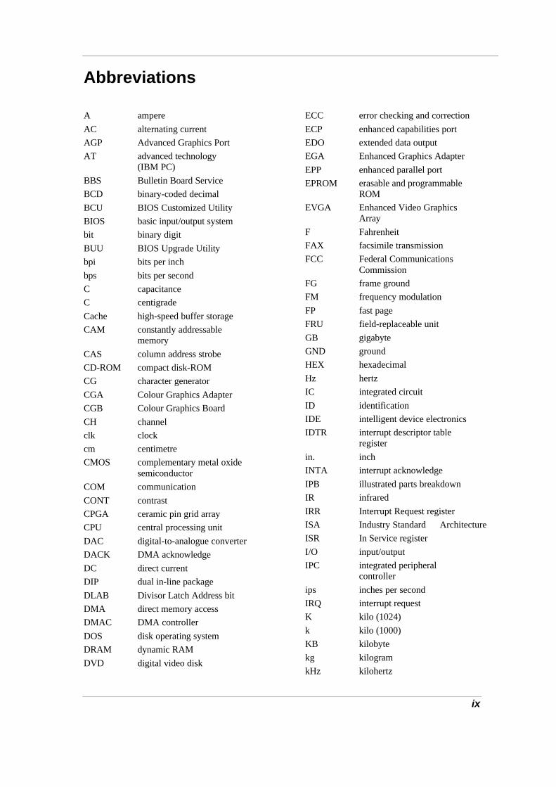
Control panel
A – CD Control Buttons or Password Buttons D – Internet ButtonB – Status LEDs E – Power ButtonC – Email Button
n CD Control Buttons — use to control the CD-ROM drive (stop, reverse, play/pause, andfast forward). Available on some systems.
n Password Buttons — set a password or personal identification number for security.Available on some systems.
n Status LEDs — keep you informed of your Versa Note VX’s current operating status.Descriptions of the status icons appear in the following section.
n Email Button — press to access your email software.
n Internet Button — press to access the Internet.
n Power Button — press the Power button either to power on or power off the system.
Note If you are unable to power off the system, use the power override. Press the Powerbutton and hold it in place until the system powers off.
Status Icons
The Versa Note VX system uses status lights marked with icons to communicate system status.See the following figure and list for each icon’s meaning.
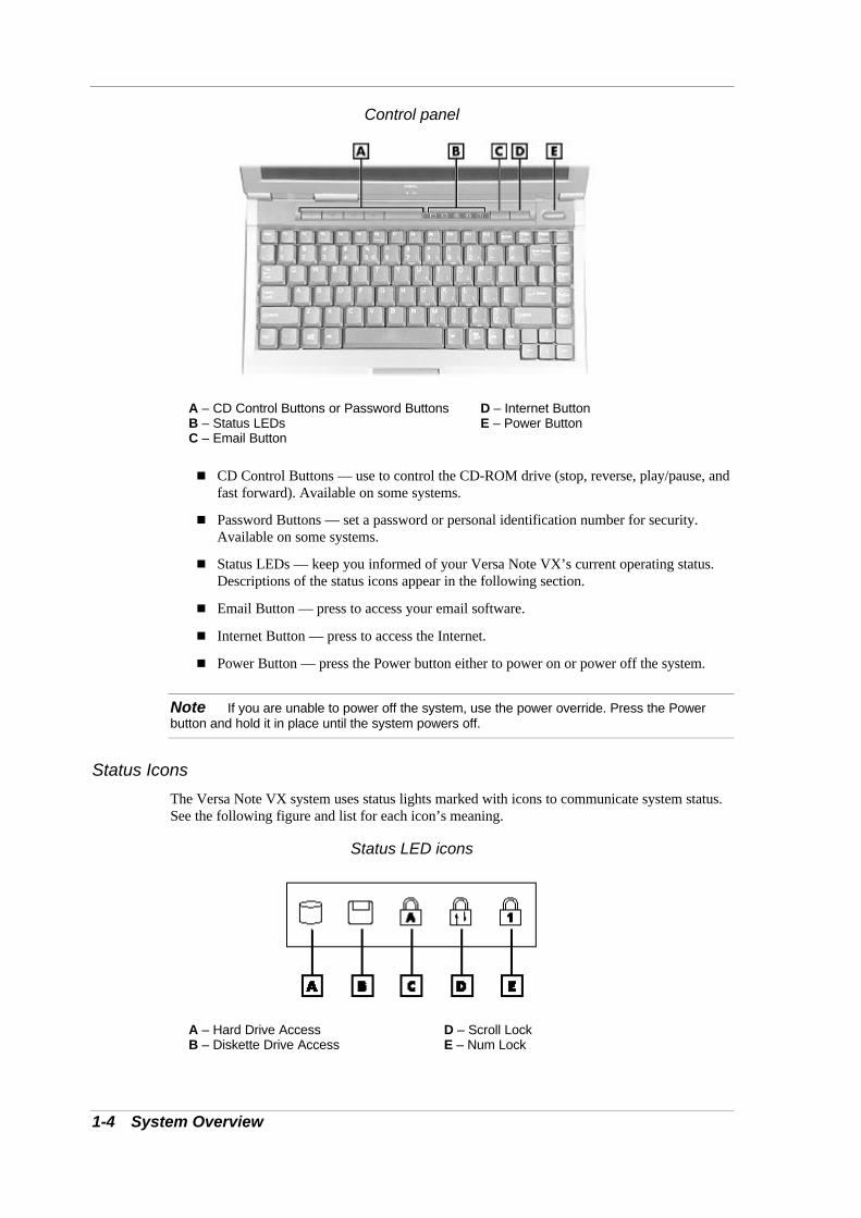
Status LED icons
A – Hard Drive Access D – Scroll LockB – Diskette Drive Access E – Num Lock

System Overview 1-5
C – Caps Lock Lock
n Hard Drive Access — lights when the Versa Note VX accesses the hard disk drive,CD-ROM drive or DVD-ROM drive.
n Diskette Drive Access — lights when the Versa Note VX writes data to or retrieves datafrom the diskette drive.
n Caps Lock — lights when caps lock is in effect.
n Scroll Lock — lights when scroll lock is in effect.
n Num Lock — lights when Num Lock mode is active.
Keyboard Panel and Base Unit
The Versa Note VX keyboard panel and base unit contain the following features. The keyboardpanel and base unit features are described after the figure.
Keyboard panel
A – Keyboard B – VersaGlide
Base unit
A – Speakers D – Audio PortsB – IR Port E – Volume ControlC – Microphone

1-6 System Overview
n Keyboard — standard QWERTY-key layout. (Models shipped outside of the U.S. areequipped with country-specific keyboard layouts.) The keyboard is equipped with manyfeatures. These include:
Function keys
Windows keys
Cursor control keys
Typewriter keys
Numeric keypad
Control keys.
Key features and operations are described after the figure.
Keyboard
A – Function Keys D – Windows Shortcut KeyB – Control Keys E – Cursor Control KeysC – Windows Start Menu Key
n Function Keys — Twelve function keys, F1 through F12, are available on the VersaNote VX keyboard. These keys work together with the Fn key to activate specialfunctions. Eight keys (printed in blue) are pre-programmed with dual functions.
Function keys are application-driven. See the specific application’s user guide forinformation about how each function key works within the application you are using.
The following function key combinations are pre-programmed for the Versa Note VX.
Fn-Left Ctrl — Simulates pressing the right control key to support IBM 327Xconnections.
Fn-F3 — Toggles the video mode between LCD only, CRT only, Simultaneous mode,and TV out.

System Overview 1-7
Fn-F4 — Sets standby power management mode on, in Windows 95.
In Windows 95, press any key to resume from Standby mode.
No function when Windows 98 configured for Advanced Configuration and PowerInterface (ACPI). In Windows 98, Standby is equivalent to Windows 95 Suspendmode. To resume from Windows 98 Standby mode, press the Power button.
Fn-F6 — Toggles the system beep off and on.
Fn-F7 — Toggles between various power management levels in Windows 95. Beepsindicate the level chosen as follows:
1 beep Off
2 beeps Custom
3 beeps Highest Performance
4 beeps Longest Life
No function when Windows 98 configured for Advanced Configuration and PowerInterface (ACPI).
Fn-F8 — Increases the LCD’s brightness (eight settings). Applies to XGA LCD panelsonly.
Fn-F9 — Reduces the LCD’s brightness (eight settings). Applies to XGA LCD panelsonly.
Fn-F10 — Provides zoom in/out control.
Fn-F12 — Toggles the scroll lock feature.
Fn-Power — Initiates a save-to-file on demand, only in Windows 95, when the BIOSSuspend option is set to “STF.” Saves your working environment to a reserved area onthe hard drive.
Fn-ESC — Initiates a Save-to-Ram, only in Windows 95, when the BIOS SystemSwitch is set to “Sleep.” Saves your working environment to memory.
Windows keys — Use the following two keys to facilitate your work.
Shortcut/Application key – provides quick access to shortcut menus. (This key actslike a right mouse button.)
Floating Window key – displays the Start menu.
n Cursor Control keys — Cursor control keys let you position the cursor on the screenwhere you want. On the screen, the cursor is a blinking underline, block, or vertical bardepending on the application. The cursor indicates where the next text typed is inserted.
n Typewriter keys — Typewriter keys (also called alphanumeric keys) are used to entertext and characters. Keys with blue print on them behave differently when combinedwith control keys or the Fn key.
n Numeric Keypad — Pressing Num Lock on the keyboard activates the numeric keypadnumbers and functions printed in blue on top of the keys.
The keypad lets you type numbers and mathematical operands (+, –) as you would on acalculator. The keypad is ideal for entering long lists of numbers.
When you press Num Lock again, the keys revert to their normal functions as typewriterkeys.

1-8 System Overview
n Control keys — Ctrl, Alt, Fn, and Shift are controls used in conjunction with other keysto change their functions. To use control keys, press and hold the control key whilepressing another key. For example, “Press Ctrl c” means to hold down the Ctrl key andtype the letter c. Key combinations work specific to the application you are running.
n VersaGlide — works like a standard computer mouse. Simply move your fingertip overthe VersaGlide to control the position of the cursor. Use the selection buttons below theVersaGlide to select menu items.
n Speakers — provides stereo sound for your multimedia presentations or listeningpleasure.
n IR Port — allows you to transfer files between you Versa and an IR-equipped desktopor notebook computer.
n Microphone — allows you to record monophonic sound directly into your notebookcomputer.
n Audio Ports
Microphone — Allows you to connect an external microphone for monophonicrecording or amplification through the unit. Plugging in an external microphonedisables the built-in microphone.
Line In — Lets you use another audio system, like a home stereo, as an inputsource. Use a cable to connect to the Line-Out port on the other audio system torecord or play.
Headphones — Lets you plug in stereo headphones or powered speakers.
n Volume Control — Allows you to control the speaker volume through the thumb wheel.
Around the Back of the SystemYou’ll find system ports for connecting your Versa Note VX to optional devices (like a printeror external monitor) on the back of your Versa Note VX. The ports are described after thefigure.
Back system features
A – Port Replicator Notches F – VGA PortB – PS/2 Port G – Serial PortC – AC Power Port H – USB PortsD – Parallel Port I – Modem/LAN PortE – Expansion Port
n Port Replicator Notches — Use these notches to secure the Port Replicator to the backof the system. (There are two Port Replicator notches located at the both ends of the rearside of the system.)

System Overview 1-9
n PS/2 Port — Use the standard PS/2 port to connect an external PS/2-style mouse,PS/2-style keyboard, or PS/2 style Numeric Keypad to the system. With an optionalY-adapter cable, you can connect up to two of these devices at the same time.
n AC Power Port — Lets you attach the Versa Note VX to the AC power source using theAC adapter that comes with your system. Keep the system connected to AC powerwhenever possible to keep the battery pack and internal CMOS battery charged.
n Parallel Port — Use this port to connect a parallel printer or other parallel device. Theparallel port default supports the Enhanced Capabilities Port (ECP) standard. The portalso supports bi-directional and output only protocols.
n Expansion Port — Use this port to connect the Port Replicator.
n VGA Port — Use this 15-pin port to attach an external monitor to your Versa Note VX.
n Serial Port — Use this port to connect a serial printer or other serial device.
n USB Ports — Each Universal Serial Bus (USB) port allows you to connect up to 127USB-equipped peripheral devices (for example, printers, monitors, scanners) to yourVersa Note VX.
n Modem/LAN Port — NEC includes a 56K fax/data modem or mini-PCI LAN.
Around the Left Side of the SystemThe left side of your Versa Note VX provides the features shown in the following figure. Theleft side features are described after the figure.
Left side features
A – Kensington Lock Latch C – Diskette DriveB – CD-ROM Drive D – Hard Disk Drive
n Kensington Lock Latch — This latch allows you to attach a Kensington security lock orother compatible lock to secure the notebook from theft.
n CD-ROM Drive — Allows you to load and start programs from a compact disc (CD)and play audio CDs.
n Diskette Drive — A 3.5-inch, 1.44-MB diskette drive comes installed in the Versa.
n Hard Disk Drive — An internal hard disk drive comes installed in the Versa. The diskdrive is upgradeable.
Around the Right Side of the SystemThe right side of the Versa Note VX offers the features shown in the following figure. The rightside features are described after the figure.

1-10 System Overview
Right side features
A – Battery Bay C – PC Card SlotsB – Fan D – TV Out
n Battery Bay — Depending upon the model, the battery bay contains a rechargeableNickel-Metal-Hydride (NiMH) or Lithium-Ion (Li-Ion) battery pack.
n Fan — Allows your system to cool properly and maintain a safe operating environment.
Do not block the fan while the Versa Note VX is in use.
n PC Card Slots — Two PC card slots allow you to insert two Type II PC cards or oneType III PC card in the bottom slot. Card BUS cards are supported and Zoom Video issupported in the top slot.
n TV Out — Allows you to connect to a television.
Around the Bottom of the SystemThe bottom of the Versa Note VX offers the following features. The features are described afterthe figure.
Bottom features
A – Battery Bay C – Memory Module Bay CoverB – Battery Release Latch D – Tilt Foot

System Overview 1-11
n Battery Bay — Equipped with a rechargeable Nickel-Metal-Hydride (NiMH) or(depending on the model) Lithium-Ion (Li-Ion) battery.
n Battery Release Latch — Slide the latch to the other end and hold it. While holding thelatch, slide the battery bay outwards to remove the battery.
n Memory Module Bay Cover — Remove the screw to find two SO-DIMM slots. One isinserted with SDRAM memory board configured by the factory. The other is empty forupgrade use.
n Tilt Foot — Adjust to provide flexible keyboard angle.
Internal ComponentsReview the following sections for a description of the system’s internal hardware.
Battery Pack
The Nickel Metal-Hydride or Lithium-Ion battery is the main power source in your Versa NoteVX computer. Chapter 9 lists battery specifications. The battery pack installs in thecompartment on the bottom of the Versa.
Diskette Drive
The Versa Note VX ships with a 3.5-inch, 1.44 MB diskette drive.
CD-ROM/DVD-ROM Drive
A 24X CD-ROM drive or a DVD-ROM drive comes installed in the Versa Note VX system.
Hard Disk Drive
A standard 2.5-inch, 9.5 mm hard disk drive ships with the system.
CMOS Battery
This lithium battery (3 Volts, 30 mAH capacity) provides battery backup and prevents data lossin the system’s complementary metal oxide semiconductor (CMOS) RAM. This memory areacontains information on the system’s configuration, for example date, time, drives, and memory.The CMOS battery charges when your Versa is connected to AC power. The CMOS batterymay discharge completely if the Versa notebook remains unused for approximately two months.
ChipSetThe following table provides information on the system chipset.
System Chipset
Chip Manufacturer Description
Intel Celeron 400, 433, or 466Intel Pentium II 366Intel Pentium III 450 or 500
Intel 366, 400, 433, 466, 450,or 500 MHz CPU
82440MX Intel System Controller
FDC37N869 Standard Microsystems Super I/O
Mobility-M Ati Video

1-12 System Overview
YMF752-S Yamaha Audio
M38813E4 Mitsubishi Keyboard Controller
TIPCI1225 Texas Instruments PCI CardBus Controller

2System Configuration and Setup
n Power Sources for Your Versa Note VX
n BIOS Setup
n Updating the BIOS
n NEC Utilities
n Application and Driver CD

2-2 System Configuration and Setup
Power Sources for Your Versa Note VXThe Versa Note VX can be powered using three different sources, making it a truly portablesystem.
Operate your Versa Note VX just about anywhere using one of the following power sources:
n the AC adapter connected to an electrical wall outlet (using AC power)
n the battery pack
n the optional auto adapter (For details about its use, refer to the accessory sheet that shipswith the option.)
Read the following sections for specific information about using the NEC power sources.
Using the AC Adapter
Use the AC adapter and power cable that came with your Versa Note VX to run your computeron alternating current (AC) power, or to recharge the battery pack. Use the AC adapterwhenever a wall outlet is nearby.
Keep the adapter connected whenever possible. The AC adapter charges the battery when it isconnected, whether the Versa is powered on or off.
AC adapter
Do not attempt to disassemble the AC adapter. The AC adapter has nouser-replaceable or serviceable parts inside. Dangerous voltage in the AC adapter can causeserious personal injury or death. The AC adapter is intended for use with a computer and mustmeet EN609050 standards.

System Configuration and Setup 2-3
Connecting the AC Adapter
Note The AC power cable type that your system uses depends on the country where you areusing it. Contact the local dealer to purchase the correct power cable.
Connect the AC adapter as follows:
1. Connect the AC adapter cable to the power port on the back of your Versa Note VX.
2. Plug one end of the AC power cable into the AC adapter and the other end into a properlygrounded 120- or 240-volt wall outlet.
Connecting the AC adapter
Do not cover or place objects on the AC adapter. Keeping the adapterclear of objects lets the adapter cool properly during use.
Only use the AC adapter that comes with your Versa Note VX. Although other adapters looksimilar, using them can damage your system.
Powering the System On and Off
To power on, locate the Power button on the right hand side of the control panel above thekeyboard and press it. To power off the system, press the Power button. In Windows, thecomputer automatically shuts down, when “Shut Down” is selected from the Start menu. That is,you do not need to press the Power button to switch off the computer.
Using the Battery
The Versa Note VX system comes with a rechargeable Lithium-Ion (Li-Ion) battery. Batterypacks are easy to install and remove.
Note Although the battery is fully charged at the factory, transit and shelf time may reducethe initial battery charge. We recommend that the first time you use your system, connect it to ACpower using the AC adapter. This also recharges your battery.
When battery power drops to the level where the Battery Warning is activated, the power LEDlights yellow.
When battery power reaches 8%, the power LED lights amber and the system beeps a warningand the system goes into Suspend/Save to File mode.

2-4 System Configuration and Setup
To prevent accidental battery ignition or explosion, adhere to thefollowing:
n Keep the battery away from extreme heat.
n Keep metal objects away from the battery terminals to prevent a short circuit.
n Make sure the battery is properly installed in the battery bay.
n Read the precautions printed on the battery.
Low Battery Power
When battery power gets low, connect your system to the AC adapter. If an AC adapter is notavailable, change the battery using the battery replacement procedure. See the section,“Replacing the Battery.”
Returning the Battery to its Normal State
To return the battery to its normal state, try the following:
n remove and then reinstall the battery
n reinstall the battery in your Versa Note VX and fully recharge the battery (to 100%).
Extending Battery Life
The Versa Note VX Li-Ion battery life is effected by the following conditions:
n When it is new and fully charged.
n When no peripherals are connected to your Versa Note VX.
n When you have no options installed.
Enabling power management features increases battery life.
While on the road, it is important to be aware of the simple things you can do to extend the lifeof the system’s main battery. Turning down the screen brightness (Fn + F9) extends battery life.
Battery Handling
Keep the following in mind when removing or replacing a battery.
n Use only the battery designed for your system in the Versa Note VX. Mixing othermanufacturers’ batteries, or using a combination of very old and new batteries candeteriorate battery and equipment performance.
n Turn off power to the system after use. Keeping system power on can degrade batteryperformance and shorten battery life.
n Clean the battery terminals with a dry cloth when they get dirty.
n Keep the battery out of the reach of children.

System Configuration and Setup 2-5
Replacing the Battery
The following symptoms indicate that battery life is nearing an end. Replace batteries thatdisplay these symptoms.
n Shorter work times.
n Discoloration, warping.
n Hot to the touch.
n Strange odour.
Replace the battery pack installed in your Versa Note VX system as follows.
Note Use the batteries in the Versa Note VX computer for which they are designed. Installinganother manufacturer’s battery, or using a combination of very old and new batteries candeteriorate battery and equipment performance.
1. Save your files, exit Windows, and put your system into Suspend mode or turn off systempower.
2. Close the LCD panel and turn over the system.
3. Remove the battery as follows:
n Locate the battery release latch.
n Slide the battery release latch and hold firmly.
n Continue to hold the battery release latch as you slide the battery out of the system.
Removing the battery
A – Battery Release Latch

2-6 System Configuration and Setup
4. Insert the new battery as follows:
n Locate the alignment groove on the edge of the battery.
n Locate the alignment groove inside the battery bay.
n Align the grooves on the battery with the grooves in the bay.
n Slide the battery into the bay until securely locked into place.
Installing the battery
5. Turn over the system.
Charging the Battery
Charge time depends on whether or not you are using the system. There are two ways to chargeyour battery while it is installed in the Versa Note VX:
n When the system is off or in Suspend mode and the AC adapter is connected, chargetime is approximately 3 hours.
n When the system is powered on and the AC adapter is connected, charge time isapproximately 4 hours.
For maximum battery performance, fully discharge the battery before recharging it. To do so,unplug the AC adapter, turn off power management features (through BIOS Setup and Windowspower management), and turn on the system. Once the battery is fully discharged, plug in theAC adapter and recharge the battery.
The warning beep that sounds when battery power becomes critically low is always a trueindicator that battery power is low. Be sure to save your data when you hear the beep and takeproper steps to provide power to your system.

System Configuration and Setup 2-7
Battery Precautions
To prevent accidental battery ignition, rupture, or explosion, adhere to the followingprecautions.
There is a danger of explosion if the battery is incorrectlyreplaced. Replace only with the same or equivalent type recommended by themanufacturer. Discard used batteries according to the manufacturer’s instructions.
To avoid personal injury and property damage, read these battery precautions on handling,charging, and disposing Li-Ion batteries.
n Keep the battery away from heat sources including direct sunlight, open fires,microwave ovens, and high-voltage containers. Temperatures over 140º F (60ºC) maycause damage.
n Do not drop or impact the battery.
n Do not disassemble the battery.
n Do not solder the battery.
n Do not puncture the battery.
n Do not use a battery that appears damaged or deformed, has any rust on its casing, isdiscoloured, overheats, or emits a foul odour.
n Keep the battery dry and away from water.
n Keep metal objects away from battery terminals. Metal objects in contact with theterminals can cause a short circuit and damage.
If the battery leaks:
n If the battery leaks onto skin or clothing, wash the area immediately with clean water.Battery fluid can cause a skin rash and damage fabric.
n If battery fluid gets into eyes, DO NOT rub; rinse with clear water immediately andconsult a doctor.
n Take extra precautions to keep a leaking battery away from fire. There is a danger ofignition or explosion.
Precautions for Recharging the Battery
Adhere to the following precautions when recharging the battery.
n Use only the NEC battery charger designed for your Versa Note VX battery type.
n Charge the battery for the specified charge time only.
n During charging, keep the environmental temperature between 5°C to 35°C (41°F and95°F).
n Read the instructions that came with the battery charger before charging the battery.
System Batteries
The Lithium-Ion battery is the main power source in your Versa Note VX computer. Chapter 9lists battery specifications. In addition to the main battery, the CMOS battery provides power tomaintain system configuration settings.

2-8 System Configuration and Setup
CMOS Battery
This battery provides battery backup and prevents data loss in the system’s complementarymetal-oxide semiconductor (CMOS) RAM. This memory area contains information on thesystem’s configuration, for example, date, time, drives, and memory.
BIOS SetupYour Versa Note VX computer comes with a hardware program called BIOS Setup that allowsyou to view and set system parameters. BIOS Setup also allows you to set password features thatprotect your system from unauthorized use.
Use BIOS Setup to:
n set the current time and date
n customize your operating system to reflect your computer hardware
n secure your system with a password
n balance your performance needs with power conservation.
Access the BIOS utility at power-on. Just press F2 when the following prompt appears.
Press <F2> to enter Setup.
When you press F2 to enter BIOS Setup, the system interrupts the Power-On Self-Test (POST)and displays the current CMOS RAM settings.
If the system detects an error during POST, it prompts you with a double beep and a message:“Press <F1> to resume.” If you press F1, the system enters BIOS Setup automatically. If youwant to fix the error, carefully read the error message that appears above the prompt (takingnotes if you want), and press F2. You will see this message if your CMOS battery becomes fullydischarged.
BIOS Setup Main Menu
After you press F2, the system displays the BIOS Setup Main Menu screen, similar to thefollowing.
BIOS Setup Main Menu

System Configuration and Setup 2-9
Use the up and down arrow keys (located on the lower right corner of the keyboard) to togglethrough the BIOS Setup menu items.
Looking at Screens
BIOS setup screens have three areas as shown next.
Advanced CMOS Setup
n Parameters — The left side of the screen. This area lists parameters and their currentsettings.
n Available Options and Help — The right side of the screen. This area lists alternatesettings and Help text for each parameter.
n Key Legend — The bottom right corner of the screen. These lines display the keys thatmove the cursor and select parameters.
Options that are greyed out are not available for the current selection.
Using Keys
The following table lists the BIOS Setup keys and their functions.
BIOS Setup Key Functions
Key Function
↑ ↓ Moves the cursor between the displayed parameters.
PgUp/PgDn Toggles through the current parameter settings.
Tab For some parameter settings, moves the cursor between thesubfields. Also moves the cursor to the next line or selection. Forexample, for System Time, Tab moves the cursor from hour to minuteto second.
ESC Exits the current screen and returns to the Main Menu screen. Fromthe Main Menu screen, displays the prompt, “Quit without saving.”
F3/F4 Changes the screen colour.
F10 Saves and exits the BIOS setup utility.

2-10 System Configuration and Setup
Checking/Setting System Parameters
The BIOS Setup Utility consists of a number of screens, each representing a specific area of theBIOS. The following tables list the BIOS parameters, their factory default settings, alternatesettings, and a description of each setting. See the item-specific help that appears on each Setupscreen for more details.
The BIOS Setup Utility is broken down as follows:
n Standard CMOS Setup
n Advanced CMOS Setup
n System Security Setup
n Power Management Setup
n Boot Device Setup
n Peripheral Setup
Resetting System Parameters
To reset all parameters to the default settings, select Auto Configuration with Defaults from theBIOS Setup Main Menu, press the arrow keys to select Yes and press Enter.
Standard CMOS Setup
Use the Standard CMOS Setup screen to view the System Time, System Date and to modifydrive parameters and related settings.
Standard CMOS Setup
Parameter Default Setting Alternate Setting(s)
Date mm/dd/yyyy
System Memory (automatically detected)
Time hh:/mm/:ss
Diskette Drive A 1.44 MB, 3 1/2 Not installed, 1.44 MB 3 1/2
Internal Auto User Defined, CDROM,Not installed
Internal Slave Auto User Defined, CD/DVD,Not installed
Boot Sector VirusProtection
Disabled Enabled
n Date — Sets your Versa Note VX’s calendar month, day and year. The calendar clock isyear 2000-compliant. These settings remain in memory even after you turn off systempower.
To set the date use the Tab or arrow keys to move from field to field. Use the PgUp orPgDn key to change the numbers within each field.
n System Memory — Displays the amount of system memory currently installed in yoursystem.

System Configuration and Setup 2-11
n Time — Sets the time, enter the current hour, minute, and second in hr:/min:/sec, 24-hour format.
To set the time use the Tab or arrow keys to move from field to field. Use the PgUp orPgDn key to change the numbers within each field.
n Diskette Drive — Designates the drive type for your diskette drive.
n Internal Drives — Assigns devices to the internal drives in your system.
n Boot Sector Virus Protection — Write protects the boot sector of the hard disk drive toavoid infection by some virus types.
Advanced CMOS Setup
Use the Advanced CMOS Setup to set the following functions.
Advanced CMOS Setup
Parameter Default Setting Alternate Setting(s)
Video Out Type NTSC PAL
LCD Panel ViewExpansion
On Off
PS/2 Port Warm Swap Enabled Disabled
Internal Mouse Enabled Disabled
n Video Out Type — Specifies the signal type used by the video device connected to theTV Out Port.
n LCD Panel View Expansion — Specifies whether the panel view is reduced/off orexpanded/on.
n PS/2 Port Warm Swap — Specifies whether or not you can swap a PS/2 device duringsystem operation.
n Internal Mouse — Specifies whether or not you can use both the internal and theexternal mouse.

2-12 System Configuration and Setup
System Security Setup
Use the System Security Setup to establish system passwords.
System Security Setup
Parameter Default Setting Alternate Setting(s)
Change SupervisorPassword
Press Enter
Change User Password Press Enter
Boot Password Required1 No Yes
Resume PasswordRequired2
No Yes
Assign HDD Password Press Enter
Internal HDD password Disabled Enabled
1 Greyed out until supervisor password is set up.2 Only active after a password is set up.
n Change Supervisor Password — Establishes password protection for entering the BIOSSetup utility, booting the system, and resuming from suspend.
n Change User Password — Establishes a user password once a supervisor password isset.
n Boot Password Required — Indicates whether or not a password is required duringsystem boot.
n Resume Password required — Indicates whether or not a password is required duringsystem resume. Boot Password must be defined to activate this parameter.
n Assign HDD Password — Allows you to assign a password to allow or restrict access tothe hard disk drive contents.
n Internal HDD Password — Enables or disables the HDD password.
Password Protection
Your Versa Note VX supports a password for system security on several levels. Your system isnot protected until you set a user password. Keep in mind that you must set the supervisorpassword before the BIOS Setup utility allows you to set a user password.
Once you set a supervisor password, you must enter it before you can enter BIOS Setup, accessthe system at startup, or resume from Suspend, depending on your configuration selection.
Establishing Passwords
To establish password protection for entering the BIOS Setup Utility or accessing the system atstartup, you must set the supervisor password before setting a user password.
n To enter a password simply select Assign Supervisor Password, enter the password, re-enter the password to confirm, and press any key to continue. Repeat the procedure toset the user password.
n To initiate password protection while you step away from your system, simply pressCtrl, Alt, Backspace. The Caps lock and Scroll lock LEDs alternately flash indicatingthat you must enter a password to resume operation.

System Configuration and Setup 2-13
In Windows 98, to establish password protection for resuming from Standby or Hibernationmodes you must do the following:
n Set a Windows password in Control Panel, Password Properties, Change Passwords.
n Enable the option “Prompt for password when the computer goes off standby,” inControl Panel, Power Management Properties, Advanced.
Hard Disk Drive Passwords
Your Versa Note VX allows you to establish password protection for the internal hard diskdrive. Hard disk drive (HDD) password protection restricts access to the drive, if the drive isremoved from your Versa Note VX and installed in another system. You are not required toenter your hard disk drive passwords while the drive remains in your current system.
The HDD passwords are written to the system BIOS and to the hard disk drive to ensure that thepassword protection travels with the drive when moved from system to system.
Establishing Hard Disk Drive Passwords
To establish password protection for your system’s hard disk drive you must establish a masterpassword, establish a user password, and enable the established passwords for the internal HDD.Follow these steps to establish HDD passwords and to enable HDD password protection.
1. Enter the BIOS setup, highlight and select the System Security Setup.
2. Highlight Assign HDD Password and press Enter.
The system prompts you to enter a master password.
3. Enter a master HDD password and press Enter.
The system prompts you to enter the password again to verify.
4. Enter the master password and press Enter.
The system confirms the creation of the master password and prompts you to enter a userpassword.
5. Enter a user password and press Enter.
The system prompts you to enter the password again to verify.
6. Enter the user password and press Enter.
7. Highlight and select Internal HDD Password and use the PgUp/PgDn keys to enable theselection. (Follow this step to enable password protection for the internal HDD.)
Changing Hard Disk Drive Passwords
To change hard disk drive passwords, enter the System Security Setup, highlight Internal HDDPassword and enter the current password that you wish to change. If you enter the current masterpassword, you are prompted to enter a new master password. If you enter the current userpassword, you are prompted to enter the new user password. If you do not wish to establish anew master or user password, press Esc instead of entering a new password.
Using Hard Disk Drive Password Protection
To facilitate the transfer of one or more HDDs between system, establish a single masterpassword (and document the password in a secure place). Establish different user passwords tolimit access to specific systems.

2-14 System Configuration and Setup
Moving the Hard Disk Drive
When a password protected HDD is moved from its original system and installed in anothersystem, error messages appear indicating that the drive is locked. Next, the Security Setupscreen appears requiring the user to enter the master password to unlock the drive. Highlight theHDD password line and enter the master password, when prompted.
If you wish to move an HDD from one system to another, follow steps 1 through 6 in thesection, “Establishing Hard Disk Drive Passwords,” before installing the HDD in a differentsystem. Install the HDD in the desired system then follow step 7 to establish HDD protection.
To take advantage of HDD password protection in another system, the system must be equippedwith the same HDD password protection feature. To determine if the system has HDDpassword, check the System Security Setup in the BIOS setup to see if there are provisions forestablishing HDD passwords.
Power Management Setup
Use the Power Management Setup to balance high performance and energy conservation.
Power Management Setup
Parameter DefaultSetting
Alternate Setting(s)
System Switch Power Button Sleep Button
Power Managementunder AC
Off On
Power Savings Level Longest Life High Perform/Custom/Off
CPU Speed Control 100% 12.5, 25, 50%
Hard Disk Timeout1 2 minutes 5/30/45 sec; 1/4/6/8/10/15 min.Off
Video Timeout1 2 minutes 30/45 sec.; 1/4/6/8/10/15 min.Off
Peripheral Timeout1 On Off
Audio Device Timeout1 On Off
Standby Timeout1 4 minutes Off/1/2/6/8/10/15 min.
Auto Suspend Timeout1 10 minutes Off/5/15/20/25/30 min.
LCD Suspend Disabled Enabled
Suspend Option Suspend STF
Auto Save-to-File Enabled Disabled
Panel Brightness Auto User Defined
Suspend Warning Tone Enabled Disabled
Remote Power On Disabled Enabled
Wake Up Alarm Disabled Enabled
Resume Alarm Time2 Off Set time in 5 min. increments whenWake Up Alarm is set.
1 Available when power savings is set to Custom.2 Resume alarm time is selectable when wake up from suspend alarm is set.

System Configuration and Setup 2-15
n System Switch — Sets the Power button as a power switch or a sleep button.
n Power Management Under AC — Specifies whether to enable power managementfeatures when AC power is in use. When AC power is connected to your Versa NoteVX system, power management is usually disabled. If you enable this parameter, thesystem automatically activates the power management profile you set, even when ACpower is used.
n Power Savings Level — Specifies one of four levels of power management.
High Performance — provides good battery life and best performance with onlyminimal power conservation Use while on the road or travelling short distances.
Longest Life — provides best battery life, the maximum amount of power savings,and good performance. Use while travelling long distances.
Off — disables power management and all device timeouts. Works well in an officeenvironment while powering your Versa Note VX with AC power.
Custom — lets you define power management levels and specific device timeoutsaccording to your own needs and present environment. Custom lets you set thefollowing timeouts.
Custom Timeout Options
Option Definition
CPU Speed Control Sets CPU performance at one of four levels.
Hard Disk Timeout Sets the time delay before your hard disk powersdown.
Video Timeout Sets whether to timeout the video or not.
Peripheral Timeout Sets whether to timeout the peripheral or not.
Audio DeviceTimeout
Sets the time delay before your audio device powersoff.
Standby Timeout Selects the system standby timeout period.
Auto SuspendTimeout
Defines how much time elapses from the time thesystem enters Standby mode to the time the systemautomatically enters Suspend Mode.
n LCD Suspend — Allows you to suspend the system when the LCD panel is closed.
n Suspend Option — Specifies either Suspend or Save to File (STF) as the default powermanagement mode.
n Automatic STF — Enables the system, after 30 minutes in Suspend mode, to save thecurrent working environment to a special file on the hard disk and to power down thesystem.
If Auto Save to File is set to Off and the save-to-file area is present on your hard drive,pressing the Fn-Power/Sleep key combination puts the system into Save to File mode.
n Panel Brightness — Selects the LCD screen brightness.
n Suspend Warning Tone — Specifies whether the system warning tone sounds whenSuspend mode starts. It is best to keep this option enabled.

2-16 System Configuration and Setup
n Wake Up from Suspend Alarm/Resume Alarm Time — Allows the alarm to wake upthe system from Suspend. Designates the time parameter in five minutes increments.
Boot Device Setup
Boot Device Setup allows you to define the following functions.
Boot Device Setup
Parameter Default Setting Alternate Setting(s)
Quick Boot Enabled Disabled
Silent Boot Enabled Disabled, Black
Boot Display Device Simul. Mode CRT only, LCD only
BootUp NumLock Auto On, Off
1st Boot Device1 CD/DVD Disabled,1st Fnd IDE,FloppyCD/DVD,SCSI,Network
2nd Boot Device1 Floppy Disabled,1st Fnd IDE,CDROM
3rd Boot Device1 1st Fnd IDE Disabled,Floppy,CD/DVD
4th Boot Device1 Disabled Floppy,CD/DVD,1st Fnd IDE
Try Other Boot Devices Yes No
1 Bootable device when set to IDE hard drive. Only one IDE device is bootable.
n Quick Boot — Specifies whether or not the system performs all tests during systemboot.
n Silent Boot — Specifies whether or not to display the NEC logo during the system boot.
n Boot Display Device — Specifies the display device(s) for system boot messages.
n BootUp NumLock — Specifies whether NumLock is On or Off at system startup.
n Boot Devices — Specifies the sequence of boot devices and whether or not the systemattempts to boot from a device other than those specified.
n Other Boot Devices — Allows you to specify IDE devices as bootable devices.

System Configuration and Setup 2-17
Peripheral Setup
The Peripheral Setup menu displays the connection locations between the system and theInput/Output (I/O) ports and lets you specify different port assignments as needed.
Peripheral Setup
Parameter Default Setting Alternate Setting(s)
USB Controller Disabled Enabled
AC’97 Audio Enabled Disabled
Internal Hard Drive Enabled Disabled
Serial Port Auto Disabled/(PnP OS Setup1)COM1,IRQ4/COM2,IRQ3COM3,IRQ4/COM4,IRQ3
Parallel Port Auto Disabled/LPT1/LPT2(PnP OS Setup1)
Parallel Mode Bi-Directional Uni-Directional/ECP/EPP
IR Serial Port Disabled Auto/(PnP OS Setup1)COM2,IRQ3/COM3,IRQ4/COM4,IRQ3
1 Appears only when configured by the Windows 98 or Windows 95 device manager.
Peripheral Setup allows you to define the following functions.
n USB Controller — Enables or disables the USB controller.
n AC’97 Audio — Enables or disables the internal sound.
n Internal Hard Drive — Enables or disables the internal hard drive.
n Serial Port — Disables the port or changes its address assignment.
n Parallel Port/Parallel Mode — Disables or reassigns the parallel port and select aparallel port mode.
n IR Serial Port — Enables, disables, or reassigns the IR serial port.
Other BIOS Setup Options
BIOS Setup offers other options, including the following:
n Change Language Setting — Controls the BIOS setup language display. English andJapanese are the available options.
n Refresh Battery — Launches the Refresh Battery utility. Once launched, the utility fullydischarges your battery to eliminate any residual memory effect. Once refreshed, yourbattery is conditioned to recharge to its full capacity. To recharge the battery, connectyour Versa Note VX to AC power. This process may take up to four hours to complete.
n Auto Configuration with Defaults — Loads default settings.
n Save Settings and Exit — Accepts changes made to current settings, saves to CMOS,and exits BIOS Setup.
n Exit Without Saving — Reverts to previously selected settings and exits Setup.

2-18 System Configuration and Setup
Updating the BIOSThe BIOS is code transmitted onto your system’s microprocessor, or central processing unit(CPU). As indicated in this chapter, you use the BIOS Setup utility to configure your system’ssoftware and hardware features. Use the BIOS Update Diskette, for your specific model, only, toupdate your Versa Note VX system BIOS.
Note You only need to update the BIOS if significant improvements or fixes to the currentsystem BIOS have been made. Your authorized dealer or service representative can help youdetermine this.
To update the system BIOS you must:
n Obtain the BIOS Update
n Prepare the BIOS Update Diskette
n Perform the BIOS Update

System Configuration and Setup 2-19
Preparing the BIOS Update Diskette
Before using the BIOS update diskette you must make the diskette BIOS flash ready. Refer tothe readme.txt file on the diskette before using the diskette.
Follow these instructions to prepare the BIOS Update Diskette.
1. Scan your hard drive for any computer viruses.
2. Enable the diskette for write access.
3. Insert the diskette into the diskette drive.
4. Type a:install at the DOS prompt and follow the on-screen instructions.
Install.bat copies the DOS system files from your hard drive onto the BIOS Update Disketteto make it BIOS flash ready.
The system prompts you when the process is complete.
5. Scan the BIOS Update Diskette for computer viruses.
The diskette is ready for use.
Performing the BIOS Update
Follow these steps to perform the BIOS update.
1. Make sure that the computer is operating under AC power and that the power is off. Insertthe BIOS Update diskette into the diskette drive.
2. Power on the computer with the diskette in the drive. The computer boots and automaticallyloads the utility. A message similar to the following appears:
The NEC BIOS Update Utility should not be used to modify the BIOS in a Versa NoteVX system which is docked. If your Versa Note VX is docked, please exit the BIOSUpdate Utility, power down, and undock your Versa Note VX before running the utility.Plug in your AC cable before restarting the flash utility.
3. Press Enter to continue.
The utility checks the currently installed BIOS version and the diskette’s BIOS version. TheMain menu appears.
4. Use the arrow keys to highlight the “Display BIOS Version” option on the Main Menu. Usethis option to check the currently installed BIOS version and the version of the newreplacement BIOS.
Press any key to return to the Main menu.
5. Highlight the “Install New BIOS” option and press Enter.
6. Press Y and then press Enter. After a brief pause, a message appears telling you to removethe diskette from the drive.
7. Remove the diskette and press any key to continue. The utility updates the BIOS.
Power off your computer. The next time you power on your computer, you will have thelatest Versa Note VX computer BIOS revision level.
8. Enter Setup to restore the default parameter settings.
9. Be sure to modify any custom settings that you may have configured.

3Disassembly and Reassembly
n Required Tools and Equipment
n Disassembly
n Reassembly
3-2 Disassembly and Reassembly
Required Tools and EquipmentAll Versa Note VX corrective maintenance procedures can be performed using the followingtools:
n Tweezers
n Small flat-head screwdriver
n Small Phillips screwdrivers (# 1 and # 0)
n needle-nose pliers
n CPU insertion/extraction tool
n 3/16” nut driver
n Right-angled dentist style probe.
DisassemblyThis section contains step-by-step disassembly procedures for the system. Reassembly is thereverse of disassembly. Each procedure is supported by a simplified disassembly illustration tofacilitate removal.
For complete disassembly of the system, follow the disassembly instructions that follow.
Note The following instructions cover two slightly different disassembly procedures. Someearlier units did not have a user-removable hard drive. Follow the instructions carefully toproperly disassemble the systems.
When disassembling the system unit, follow these general rules.
n Turn off the system and disconnect all power and all options, including the AC adapter(if connected) and battery pack (see the procedures that follow).
n Do not disassemble the system into parts that are smaller than those specified in theprocedure.
n Label all removed connectors. Note where the connector goes and in what position itwas installed.
Battery
Replace the battery pack installed in your Versa Note VX system as follows.
Note Use the batteries in the Versa Note VX computer for which they are designed. Installinganother manufacturer’s battery, or using a combination of very old and new batteries candeteriorate battery and equipment performance.
1. Save your files, exit Windows, and put your system into Suspend mode or turn off systempower.
2. Close the LCD panel and turn over the system.

Disassembly and Reassembly 3-3
3. Remove the battery as follows:
n Locate the battery release latch.
n Slide the battery release latch towards the back of the system and hold firmly.
n Continue to hold the battery release latch as you slide the battery out of the system.
Removing the battery
A – Battery Release Latch
Memory Module and Switch Settings
Use the following steps to remove the memory module and access the switch settings.
1. Power off the system and disconnect any peripheral devices.
2. Turn the system over and locate the screw on the memory bay.
Memory bay cover and screw
A – Memory Bay Cover B – Screw
3. Remove the screw and lift off the memory bay cover.

3-4 Disassembly and Reassembly
4. Locate the memory module slot.
5. To remove a SO-DIMM, press the locking tabs away from the sides of the module until themodule pops up. Then, remove the SO-DIMM.
Removing the memory module
Switch Settings
A six-position dip switch is located on the bottom of the system. The switch is accessible byremoving the access panel beneath the CD-ROM drive. The following list identifies each switchsetting and its function.
n Switch 1, Password override — The default setting is “OFF.” If you forget yourpassword and cannot access the data on your Versa, change the setting to “ON” andyour current password is erased.
n Switch 2 — Keyboard select; Default is “ON” for U.S. 85 key keyboard.
n Switch 3 — Reserved for factory use; Default is “OFF.”
n Switch 4 — Keyboard select; Default is “ON” for U.S. 85 key keyboard.
n Switch 5 — Password enable; Default is “ON” (enabled).
n Switch 6 — Logo select; Default is “OFF” for U.S.
Default switch settings

Disassembly and Reassembly 3-5
Hard Disk Drive
To remove the hard disk drive, follow these steps.
1. Locate the drive access panel on the left side of the system. Open the panel using the notch.
Opening the panel
A – Drive Access Panel B – Notch
2. Remove the screw that secures the hard disk in the system.
Removing the screw
A – Screw

3-6 Disassembly and Reassembly
3. Slide the hard disk drive out of the system.
Removing the disk drive
LED/Button Assembly
Follow these steps to remove the LED/Button assembly.
1. Open the LCD panel.
2. Locate the LCD hinge covers. Locate and remove the screw caps and screws on the hingecovers.
Removing the screw caps and screws
A – Screw Cap

Disassembly and Reassembly 3-7
3. Slide each hinge cover toward the outside edge of the system and remove.
Removing the hinge covers
A – Hinge Cover
4. Lift the LED/button assembly away from the system.
Removing the LED/button assembly
A – LED/Button Assembly
LCD Panel
Use the following steps to remove the LCD panel.
1. Remove the LED/button assembly from the system.
2. Close the LCD panel and turn the system over.

3-8 Disassembly and Reassembly
3. Locate and remove the two bottom screws securing the LCD panel to the system.
Removing the screws
A – Screws
4. Turn the system over and open the LCD panel.
5. Locate and remove the two hinge screws.
Removing the hinge screws
A – Screw
Disassembly and Reassembly 3-9
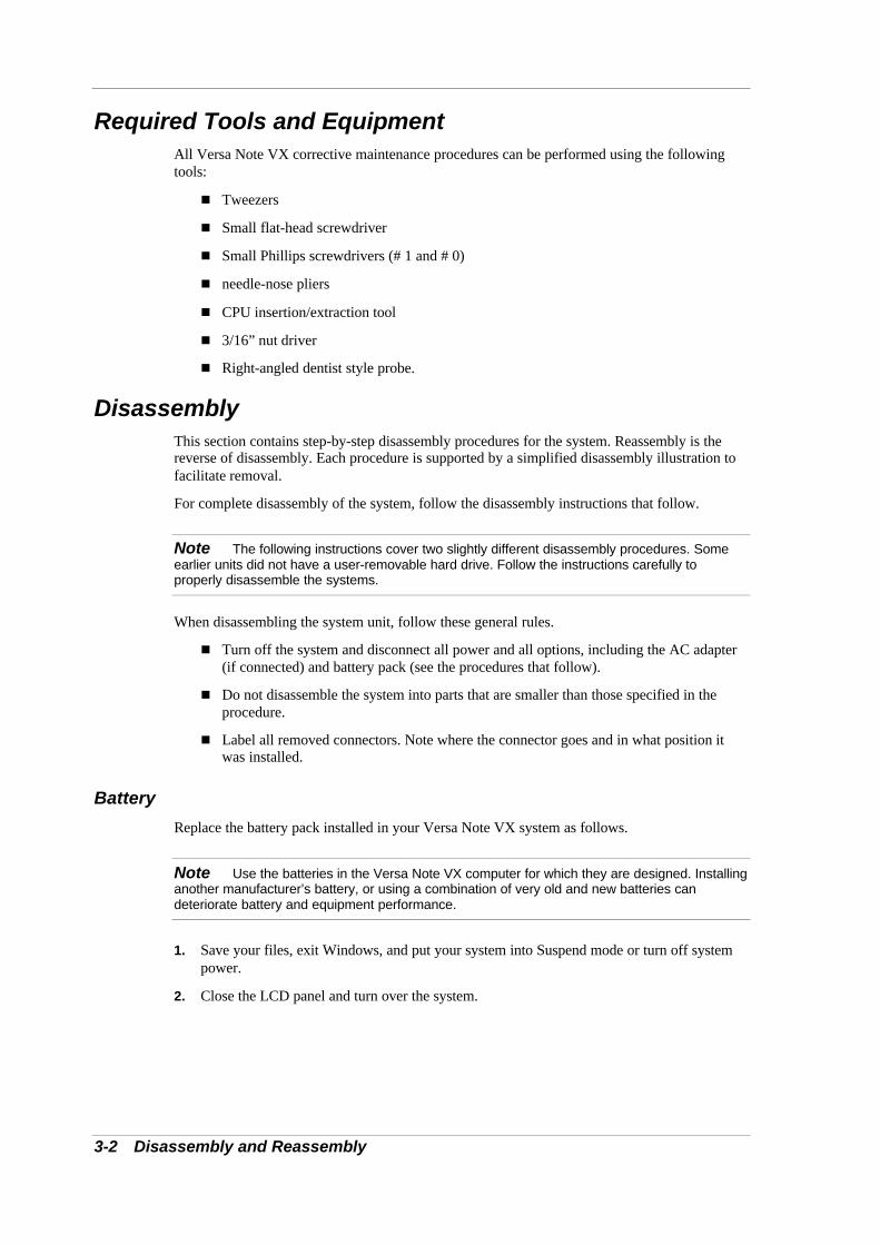
6. Locate and remove the two screws securing the LCD panel connector to the main board.
Removing the LCD panel screws
A – Screws
7. Pull the LCD panel up and away from the system.
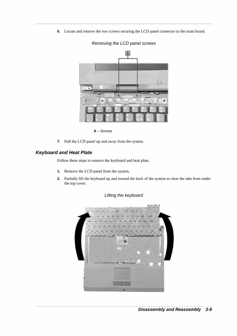
Keyboard and Heat Plate
Follow these steps to remove the keyboard and heat plate.
1. Remove the LCD panel from the system.
2. Partially lift the keyboard up and toward the back of the system to clear the tabs from underthe top cover.
Lifting the keyboard

3-10 Disassembly and Reassembly
3. Lay the keyboard key side down over the back of the system.
4. Locate and completely loosen the four screws securing the heat plate to the system. Do notattempt to remove the screws.
Loosening the heat plate screws
A – Screws B – Heat Plate
5. Partially lift the heat plate. Disconnect the fan cable from connector P5 of the main boardand remove the heat plate.
6. Disconnect the keyboard cable from connector P5 of the I/O board and remove thekeyboard.
Top Cover
Use the following steps to remove the top cover.
1. Remove the LCD panel, keyboard, and heat plate from the system.
2. Turn the system over.

Disassembly and Reassembly 3-11
3. Remove the ten screws on the bottom that secure the top cover to the system.
Removing the bottom screws
A – Screws
4. Turn the system over.
5. Locate and remove the one screw inside the hard disk drive bay that secures the top cover.
Removing the drive bay screw
A – Screw

3-12 Disassembly and Reassembly
6. Locate and remove the one screw on the top that secures the top cover.
Removing the top screw
A – Screw
7. Partially lift the top cover. Disconnect the VersaGlide cable from connector P8 on the I/Oboard. Remove the top cover.
Removing the top cover
A – VersaGlide Cable
VersaGlide
Follow these steps to remove the VersaGlide assembly.
1. Remove the LCD panel, keyboard, heat plate, and top cover from the system.

Disassembly and Reassembly 3-13
2. Turn the top cover over and locate the three screws securing the VersaGlide. Remove thescrews.
Removing the VersaGlide screws
A – VersaGlide B – Screws
3. Slide the VersaGlide assembly away from the top cover tabs and remove the VersaGlidefrom the top cover.
CD-ROM Drive
Use the following steps to remove the CD-ROM drive.
1. Remove the LCD panel, keyboard, heat plate, and top cover from the system.
2. Slide the CD-ROM drive out of the system and away from the connector on the main board.
Removing the CD-ROM drive
A – CD-ROM Drive

3-14 Disassembly and Reassembly
Audio Board
Follow these steps to remove the audio board.
1. Remove the LCD panel, keyboard, heat plate, and top cover from the system.
2. Carefully disconnect the audio board from connector P7 on the main board by lifting theaudio board.
Disconnecting the audio board
A – Audio Board
3. Disconnect the cables from connectors P1 and P2 on the audio board and remove the audioboard.

Disassembly and Reassembly 3-15
DC/DC Board
Use the following steps to remove the DC/DC board.
1. Remove the LCD panel, keyboard, heat plate, and top cover from the system.
2. Carefully disconnect and remove the DC/DC board from connectors P9 and P10 on themain board by lifting the DC/DC board.
Disconnecting the DC/DC board
A – DC/DC Board

3-16 Disassembly and Reassembly
I/O Board
Follow these steps to remove the I/O board.
1. Remove the LCD panel, keyboard, heat plate, top cover, and audio board from the system.
2. Disconnect the diskette drive cable from connector P6 on the I/O board.
3. Disconnect the CMOS battery from P1 of the I/O board.
4. Carefully disconnect and remove the I/O board from connector P12 on the main board bylifting the I/O board.
Disconnecting the I/O board
A – I/O Board

Disassembly and Reassembly 3-17
CMOS Battery
Use the following steps to remove the CMOS battery.
1. Remove the LCD panel, keyboard, heat plate, top cover, audio board, and I/O board fromthe system.
2. Remove the CMOS battery from the front of the base assembly. It is secured with two-sidedtape.
Removing the CMOS battery
A – CMOS Battery
Microphone
Follow these steps to remove the microphone.
1. Remove the LCD panel, keyboard, heat plate, top cover, audio board, and I/O board fromthe system.
2. Remove the microphone assembly from the front of the base assembly.
Removing the microphone assembly
A – Microphone Assembly

3-18 Disassembly and Reassembly
Diskette Drive
Use the following steps to remove the diskette drive.
1. Remove the LCD panel, keyboard, heat plate, top cover, audio board, and I/O board fromthe system.
2. Locate and remove the two screws securing the diskette drive to the base assembly.
Removing the diskette drive screws
A – Screws B – Diskette Drive
3. Lift the diskette drive out of the base assembly. Slightly tilt the drive front side down toslide the drive release button out of the base assembly.

Disassembly and Reassembly 3-19
Speakers
Follow these steps to remove the speakers.
1. Remove the LCD panel, keyboard, heat plate, top cover, audio board, and I/O board fromthe system.
2. Slide the speaker up out of the front of the base assembly. There are two speakers.
Removing the speaker
A – Speaker
Kensington Lock Latch
Use the following steps to remove the Kensington lock latch.
1. Remove the LCD panel, keyboard, heat plate, and top cover from the system.
2. Locate and remove the two screws securing the lock latch to the main board.
Removing the lock latch screws
A – Screws B – Lock Latch
3. Lift the Kensington lock latch out of the base assembly.

3-20 Disassembly and Reassembly
Main Board
Follow these steps to remove the main board.
1. Remove the LCD panel, keyboard, heat plate, top cover, audio board, I/O board, diskettedrive, and Kensington lock latch from the system.
2. Locate and remove the four screws that secure the main board to the base assembly. Use theneedle-nose pliers to remove the three hex screws.
Removing the main board screws
A – Hex Screws C – Main BoardB – Screw
3. Lift the main board out of the base assembly.
Celeron/Pentium II Removal
Follow these steps to remove theCeleron/Pentium II CPU.
1. Remove the LCD panel, keyboard, heat plate, top cover, audio board, I/O board, diskettedrive, Kensington lock latch, and main board from the system.

Disassembly and Reassembly 3-21
2. Locate the CPU. Locate and remove two of the CPU stand-offs.
Removing the CPU stand-offs
A – Stand-offs
3. Locate pin 1 on the CPU (identified by the triangle). Align and place the actuation block ofthe insertion/extraction tool over pin 1 and the pin diagonally opposite pin 1.
Placing the actuation block
A – Pin 1

3-22 Disassembly and Reassembly
4. Place the push rod into the hole closest to pin 1 of the CPU. To release the CPU, push therod toward pin 1 until you feel the mechanism unlock.
Releasing the CPU
5. Lift the actuation block and the CPU out the system.
Only touch the CPU on the sides. Do not touch the top of the die.
Pentium III Removal
Follow these steps to remove the Pentium III CPU.
1. Remove the LCD panel, keyboard, heat plate, top cover, audio board, I/O board, diskettedrive, Kensington lock latch, and main board from the system.
2. Locate the CPU. Locate the locking screw just below the CPU. Using a flat headscrewdriver, turn the locking screw counter clockwise to unlock the CPU.
Lift the CPU out of the socket.
Removing the locking screw
A – Screw

Disassembly and Reassembly 3-23
Only touch the CPU on the sides. Do not touch the top of the die.
PC Card Assembly
Follow these steps to remove the PC card assembly.
1. Remove the LCD panel, keyboard, heat plate, top cover, audio board, I/O board, diskettedrive, Kensington lock latch, and main board from the system.
2. Turn the main board over.
3. Remove both memory modules, if present.
4. Locate and remove the four screws that secure the PC card assembly to the main board.
Removing the PC card screws
A – Screws B – Main Board (back)
5. Disconnect the PC card assembly from connector P2 on the main board and remove theassembly.
ReassemblyReassembly is the reverse of the disassembly process. Use care to insure that all cables andscrews are returned to their proper positions.

4System Board Layout
n Audio Board
n DC/DC Board
n I/O Board
n Main Board

4-2 System Board Layout
This following figures show the system boards and connector locations.
Audio Board
A – Connector P2 (back side) C – Connector P5B – Connector P1 (back side)
DC/DC Board
A – Connector P1 B – Connector P2

System Board Layout 4-3
I/O Board
A – Connector P5 D – Connector P2B – Connector P3 (back side) E – Connector P1C – Connector P6 F – Connector P8
Main Board
A – Connector P17 F – Connector P5B – Connector P15 G – Connector P4C – Connector P10 H – Connector P7D – Connector P8 I – Connector P9E – Connector P2 J – Connector P12

5Preventive Maintenance
n Cleaning the Notebook Exterior
n Cleaning the Notebook Interior
n Protecting the Disk Drive
n Handling the Battery Pack
n Maintaining the LCD Quality

2 Preventive Maintenance
Preventive maintenance is limited to cleaning the plastic case, the keyboard, the display screen,and the diskette drive heads, as required.
Note Remove the battery and disconnect the AC adapter before performing anymaintenance. Voltage is present inside the system unit and LCD even after the system is turnedoff.
Cleaning the Notebook ExteriorUse the steps below to clean the outer surface of the system.
1. Power off the system and remove the battery pack. Unplug all cables connected to thesystem.
2. Wipe the outside of the system, keyboard, and display with a soft, clean cloth. Removestains with a damp, almost dry cloth. Use glass cleaner to clean the LCD. Apply the glasscleaner directly to the cloth and then wipe the LCD. Do not use solvents or strong, abrasivecleaners on any part of the system.
3. Clean the keys with a damp cloth. A small, soft-bristle brush may be used to clean betweenthe keys. Make sure to use a damp cloth (not wet) to prevent moisture from seepingbetween the keyboard and the metal plate, possibly damaging the components under thekeys. If the keyboard gets wet, thoroughly dry it before reassembling the system unit.
Cleaning the Notebook InteriorWhen servicing the inside of the notebook, remove dust and other foreign particles from insidethe system unit as follows:
1. Remove the top cover and keyboard using the disassembly procedures discussed in thesection, Disassembly and Reassembly, in Chapter 3.
2. Dust or vacuum (with a rubber-tipped nozzle) the inside of the system, particularly the mainboard surface. Use care to avoid damaging or dislodging any components or cables.
3. Inspect all cables connectors for damage. Ensure that connectors are seated properly beforereplacing the cover.
Protecting the Disk DriveTo protect the disk drive and data, back up the system disk periodically on diskettes.Periodically use a head-cleaning diskette in the disk drive to prolong the life of the drive and tohelp maintain data integrity.
Here are some maintenance procedures to use when servicing a hard disk:
n Always back up the data files from the hard disk.
n Run a virus detecting program to check for possible virus infected areas on the harddisk.
n Use the preinstalled ScanDisk program to correct any errors found in the directory andFile Allocation Table (FAT). This also frees up space from any unused sectors.
n Never turn the computer off when the hard disk is being accessed.
n Never move or raise the computer while the hard disk is being accessed. Be especiallycareful not to jar the hard disk during access, this can cause a hard disk crash.

Preventive Maintenance 3
n Use hard disk maintenance program like DEFRAG under DOS, or acquire NortonUtilities SPEEDISK programs. These programs reorganize your hard disk byeliminating fragmentation and improve the hard disk access time.
Handling the Battery PackThe battery pack furnished with the computer requires reasonable care and handling to ensureefficient operation and maximum life. Periodically inspect the battery terminals and the batteriesfor evidence of corrosion and oxide build-up.
To ensure that the battery pack endures for a normal life cycle, always observe the followingprecautions when handling the battery pack:
n Do not drop the battery pack or subject it to excessive shock and vibration.
n Do not expose the battery pack to direct sunlight, moisture, chemical compounds, orextreme heat.
n Do not disassemble the battery pack.
n Do not use the battery pack to power other devices.
n Do not short the battery leads or connect the battery with reversed polarity.
n Never attempt to charge the battery pack in any way other than as described in thismanual and the user’s guide.
n Always charge the battery pack as soon as possible after a low battery indication.
Maintaining the LCD QualityWhen it comes to screen problems, heat plays a big part. After a good working session, thetypical routine is to shut the machine and close the cover. The display surface (no matter whattype it is) radiates heat. When you close the cover, you trap the heat against the screen. Makesure to leave the computer’s cover open for about ten minutes while the heat disperses, beforeclosing the LCD.

6Troubleshooting
n Quick Troubleshooting
n Helpful Questions

2 Troubleshooting
Quick TroubleshootingThis section summarizes problems that may develop during system operation and lists suggestedcorrective actions.
Quick Troubleshooting
Problem or Symptoms Corrective Actions
No power Check that the AC adapter is plugged into the power port of thenotebook. Also, check that the AC adapter is plugged into a properlygrounded AC power outlet.
If using the battery as the main power source, check if the battery packis the correct type, charged properly, and is inserted correctly.
Check if the internal DC/DC board of the notebook is correctly insertedinto the main board. Otherwise, replace the DC/DC board.
Power LED is on but nodisplay and system does notturn on
Check if the memory module is inserted properly. Also insert themodule into the other slot.
Check that the CPU is inserted properly.
Replace the memory module, CPU, or DC/DC board.
Display on the LCD isunreadable
Adjust the brightness.
Check if the installed VGA driver is correct and resolution is setaccording to the LCD size and type.
Check if the LCD panel is connected properly.
Replace the main board.
LCD screen does not showdisplay
Check if the power saving mode is activated. Press any key or pressthe Power button to resume operation and display.
Check if the display output is switched to the external monitor.
Check if there is power.
Check if the LCD panel is disconnected or loose.
Replace the LCD inverter board found inside the LCD panel.
Battery power does not lastlong
Make sure that the power management options under BIOS Setup areenabled and set properly.
Recharge the battery pack for at 3 least hours before using.
Discharge and recharge the battery twice.
Replace the battery pack.
System halts during bootsequence
Check condition of the selected bootload device (diskette or hard disk)for bad boot track or incorrect O/S files.
Try booting from a new boot diskette and recopy or repartition the harddisk.
Check for any BIOS error messages on the display.
Replace the main board.
I/O processing malfunctions Check the connections of all internal devices.
Replace the main board.

Troubleshooting 3
Quick Troubleshooting
Problem or Symptoms Corrective Actions
Diskette drive does not work Check if the diskette drive option is not installed in BIOS Setup.
Check if the diskette drive cable is connected properly.
Check that the diskette is not faulty.
Replace the diskette drive.
Replace the main board.
Hard disk drive malfunction Check if the hard disk drive is set properly in BIOS Setup.
Check the connection.
Check if the disk drive is working properly. If not, replace the drive.
Replace the main board.
CD-ROM drive malfunction Check if the drive is set properly in BIOS Setup.
Check if the device driver is installed properly. Do not use any otherCD-ROM driver.
Check the connection.
Replace the drive or main board.
Memory malfunction Check if the memory module is inserted properly. Try to insert it into theother slot.
Replace the memory module.
Replace the main board.
External keyboard or PS/2mouse does not work
Check if the keyboard or mouse is connected properly. Check if thePS/2 Y-cable is being used. Power off the system first before pluggingin the device.
Check if the PS/2 mouse driver is installed properly.
Replace the keyboard or mouse.
Replace the main board.
PC card does not work Check if the PC card is inserted properly and check the connection.
Check the PC card driver installation for an IRQ conflict. Try to disablethe COM2 port in BIOS Setup menu to free up an unused IRQ.
If the PC card is not detected, insert it to the other PC slot. Otherwise,replace the PC card.
Contact the PC card manufacturer for support.
Replace the main board.
VersaGlide does not work Check if PS/2 or Alps mouse driver is properly installed.
Check if the VersaGlide cable inside the system is inserted properly.
Replace the VersaGlide module.
Check the keyboard controller chip for any cold or loose soldering.
Replace the main board.

4 Troubleshooting
Quick Troubleshooting
Problem or Symptoms Corrective Actions
Serial device does not work Check if the serial port is set to “Auto” in BIOS Setup.
Check if the serial device is connected properly.
Check if the mouse driver is installed properly.
Replace the serial device.
Check the I/O controller chip for any cold or loose soldering.
Replace the main board.
Parallel device does not work Check if the parallel port is set to “Auto” in BIOS Setup.
Check if all connections are properly set.
Check if the external device is turned on.
Check if the printer mode is set properly.
Check the I/O controller chip for any cold or loose soldering.
Replace the main board.
IR Port does not work. Check if the IR port (COM2) is enabled in BIOS Setup.
Check if File Sharing and the Computer name are both set properly.
Check if the Infrared Monitor is activated.
Check if the IR ports on both systems are blocked or obstructed.
Check the I/O controller chip for any cold or loose soldering.
Replace the main board.
USB Port does not work Check if the USB controller in BIOS Setup is enabled.
Check the USB device connection. Unplug and re-plug the device.
Check if the USB port driver and the USB device driver are installed.
Replace the USB device or contact the USB device manufacturer forsupport.
Replace the main board.
Audio components do notwork
Check that the external connections and that the volume mixer are setproperly.
Check if the audio source (CD, tape, etc.) is faulty.
Check if the audio driver is installed.
Check if the internal connections for speaker and microphone areworking.
Check the audio board, cables, and connections.
Replace the main board.

Troubleshooting 5
Helpful QuestionsHere are some helpful questions to ask when troubleshooting the notebook:
n Is there any external power source connected to the computer?
n Is the battery fully charged?
n Is the computer turned on and the Power LED activated?
n Is the LCD display switched to the external monitor?
n Are all cables and devices connected properly and securely?
n Are all needed device drivers installed properly?
n Is the Suspend Mode activated? Press any key or press the Power/Sleep button topower on the system.

7Specifications
n System Components
n Connector Locations
n Memory Map
n Interrupt Controllers

2 Specifications
System ComponentsThe following system component specifications are standard except where noted.
System ProcessorDepending on the model:
n Intel Celeron 400 MHz, 433 MHz, or 466 MHz
n Intel Pentium II 366 MHz
n Intel Pentium III 450 MHz or 500 MHz
Random Access Memory (RAM)n Standard Main Memory — 64 MB high-speed interleaved access
n Optional Expansion — 1 SO-DIMM slot
Expandable in 64-MB or 128-MB increments
Maximum 256 MB total
n Video RAM — 4.0 MB
n Cache RAM — 128-KB L2 cache (Celeron) or 256-KB L2 cache (Pentium II andPentium III)
Read-Only Memory (ROM)512-KB flash ROM with boot block
Calendar ClockYear/month/day/hour/minute/second maintained by internal back-up battery
Input/Output (I/O) FacilitiesIntegrated industry-standard interfaces
n Modem Port — 1 port, RJ-11 jack or LAN Port on some models
n TV Out — 1 port, 2-pin RCA jack, NTSC/PAL support
n DC In — 1 port for AC adapter cable
n PS/2 Port — 1 port, PS/2, 6-pin MiniDin
n Parallel — 1 port, 25-pin D-sub
n USB Ports — 2 ports, base connector
n Expansion — 1 port, 80-pin for optional Port Replicator
n Serial — 1 port, 9-pin D-sub
n VGA — 1 port, 15-pin high-density D-sub
n Infrared — 1 port
n Microphone — 1 port, 3-pin, Mini-Pin jack
n Line-In — 1 port, 3-pin, Mini-Pin jack
n Headphones — 1 port, 3-pin, Mini-Pin jack

Specifications 3
Main Batteryn Types:
Lithium-Ion (Li-Ion), eight cell
– Output Voltage – 14.4v
– Capacity – 3,600 mAh
n Recharging Time
Lithium-Ion (Li-Ion):
Approximately 3.5 hours when system is not in use; approximately 4 hours whensystem is in use.
Card SlotsTwo 32-bit card slots for two Type II or one Type III PC card, 5 V or 3.3 V interface
LCD Displayn Panel (depending on the model):
12.1-inch Thin Film Transistor (TFT) cold-cathode fluorescent tube (CCFT) backlitSuper VGA colour
13.3/14.1-inch Thin Film Transistor (TFT) Extended Graphics Array (XGA) colour
n Resolution
800 x 600 pixels for SVGA
1024 x 768 pixels for XGA
KeyboardMembrane-type, with standard QWERTY-key layout (International keyboards are countryspecific)
n Function keys — 12 keys
n CD Control keys or Personal Code keys
n Internet and Email keys
n Cursor Control keys — 8 keys; arrow keys arranged in inverted T layout
n Numeric keypad — embedded
n Special Windows 95 keyset
n Fn key — function key for ROM-based key functions
Diskette DriveStandard 1.44 MB
n Size — 3.5 inch
n Capacity — 1.44 MB (formatted), 2 MB (unformatted)
Hard Disk Drivesn Internal, 2.5 inch, IDE

4 Specifications
n Capacity (depending on the model) 6.0-GB, 12-GB, or larger hard disk drive
CD-ROM Driven Thin-type CD-ROM Pack
n Access Time — 24X
n Interface — IDE (ATAPI)
n Photo CD Compatibility — Multisession Photo CD, Single Session Photo CD, VideoCD, CS-I, CD-I Ready, CD-G and CD-Plus
Mini-PCI Modemn K56 Flex compatible
n V.34 extended rate protocol
n V.90 compliant
n Enhanced AT command set
n Class 1 and 2 Fax protocols
n Built-in speaker with software controllable volume
Mini-PCI LANn 10Base-T and 100Base-TX
n Resume-on-LAN support
n Full duplex support
n Auto-sensing
n Software support for management server
Mini-PCI Modem/LANModem
n K56 Flex compatible
n V.34 protocol
n V.90 compliant
n Class 1 Fax protocol
LAN
n 10/100 Ethernet
n Full duplex support
n Wake-on-LAN support
n Auto-sensing
n Low power features
AC Adaptern Input Voltage 100 to 240 volts (V) AC, 50 watt (max.)
n Output Voltage 19 volts DC, 2.6A

Specifications 5
Dimensions System
n Width — 12 in. (307 mm)
n Depth — 9.9 in. (252 mm)
n Height — 1.6 in. (40 mm) (max 44 mm)
Weightn 6.6 lbs. (3.0 kg) 12.1-inch LCD
n 6.8 lbs. (3.1 kg) 13.3-inch LCD
n 7.0 lbs. (3.2 kg) 14.1-inch LCD
Recommended EnvironmentOperation
n Temperature — 5ºC to 35ºC (41ºF to 95ºF)
n Relative Humidity — 20% to 80% (Noncondensing)
Storage
n Temperature — –20ºC to 40ºC (–4ºF to 104ºF)
n Relative Humidity — 20% to 80% (Noncondensing)

6 Specifications
Connector LocationsThe following table shows the system’s connector locations.
Connector Locations
Connector Location
P1 Audio Board
P2 Audio Board
P1 I/O Board
P5 I/O Board
P6 I/O Board
P8 I/O Board
P2 Main Board
P5 Main Board
P7 Main Board
P9 Main Board
P10 Main Board
P12 Main Board

Specifications 7
Memory MapThe system supports system and video shadowing, both controlled through complementarymetal oxide semiconductor (CMOS). The system supports BIOS as a cacheable area with writeprotection. The following table shows the system’s memory map.
System Memory Map
Memory Space Size Function
00000000h-0009FFFFh 640 KB System Memory
000A0000h-000BFFFFh 128 KB Video Memory
000C0000h-000DFFFFh 128 KB
000E0000h-000FFFFFh 128 KB System and Video BIOS
01000000h-01FFFFFFh 32 MB Extended Memory
02000000h-03FFFFFFh 32 MB Extended Memory
04000000h-0FFFFFFFh Up to 256 MB Extended Memory

8 Specifications
Interrupt ControllersThe following table shows default interrupt level assignments 0 through 15.
Interrupts
IRQ# Device
IRQ00 Internal Timer
IRQ01 Keyboard
IRQ02 Cascade
IRQ03 IR
IRQ04 Serial Port
IRQ05 CardBus/Mini-PCI/Sound
IRQ06 Diskette Drive
IRQ07 Parallel Port
IRQ08 Real-time Clock
IRQ09 USB
IRQ10 Video
IRQ11 Available
IRQ12 Mouse
IRQ13 Coprocessor
IRQ14 Hard Disk Controller
IRQ15 Available

Glossary 1
Glossary
A
applications programs Software designed to perform specific functions, like solving business or mathematicalproblems.
AC Adapter A device that connects an NEC Versa portable computer and an AC wall outlet to provideAC power for running the system or recharging the battery.
B
base RAM Area of system memory between 0 and 640 kilobytes available to the user for operatingsystem and application programs.
BIOS Basic Input Output System. A collection of primitive computer routines, usually burnt intoROM, that controls the real-time clock, keyboard, disk drives, video display, and otherperipheral devices.
bit Binary digit. The smallest unit of computer data.
bits per second (bps) A unit of transmission. Also called baud rate.
board Printed circuit board. Board onto which computer components are soldered and thin wiresare printed to connect the components.
boot To start up a computer. See cold boot and warm boot.
bus An electronic circuit within a computer used for transmitting data or electrical power fromone device to another.
byte Group of eight contiguous bits.

2 Glossary
C
clock Electronic timer used to synchronize computer operations.
CMOS Complementary Metal Oxide Semiconductor. A chip that contains nonvolatile memory inthe NEC Versa. CMOS is backed up by an internal lithium battery that preservesclock/calendar data and system configuration parameters stored in CMOS.
cold boot Process of starting up the computer by turning on the power. If power is already on, theprocess means to turn off the computer and turn it on again. A cold boot reinitializes alldevices.
CRT Cathode-Ray Tube. A type of display screen used in desktop monitors. It forms the screenimage using tiny dots called pixels. See also LCD.
cursor A movable image on the display screen that indicates where the next entered data appears.
D
diskette A thin flexible platter coated with a magnetic material for storing information.
diskette drive A magnetic drive that writes on and retrieves data from a diskette.
DSTN Double-Scan Super-Twisted Nematic. A type of technology used in some NEC Versa LCDscreen displays.
E
enhanced VGA A video interface that offers more colours or higher resolution than VGA.
extended RAM The area of RAM above the first megabyte of memory in the system available forenhancing system performance.
F
function key The set of keys on the keyboard (usually F1 through F12) that let you get help and errormessage information or quickly select frequently used commands.

Glossary 3
H
hard disk A rigid magnetic storage device that provides fast access to stored data.
hardware The electrical and mechanical parts from which a computer is made.
hertz (Hz) A unit of frequency equal to one cycle per second.
hot key Combination of two or three keys (such as Ctrl-Alt-Del) that you press simultaneously fora particular function.
I
input/output (I/O) The process of transferring data between the computer and external devices.
IDE Intelligent Drive Electronics. A hard disk drive type that has controller electronics built intothe drive and delivers high throughput.
interface A connection that enables two devices to communicate.
interrupt A special control signal from an I/O device that diverts the attention of the microprocessorfrom the program to a special address.
K
kilobyte (KB) 1024 bytes.
L
LAN Local Area Network.
LCDLiquid Crystal Display. An LCD consists of a thin sandwich of two glass plates with sealededges, containing nematic liquid-crystal material that forms the screen image. The NECVersa displays are LCD type.
load To copy a program into the computer's memory from a storage device.

4 Glossary
M
megabyte (MB) 1,048,576 bytes.
memory Electronic storage area in a computer that retains information and programs. A computerhas two types of memory — read-only memory (ROM) and random access memory(RAM).
menu A video display of programs or options.
microprocessor A semiconductor central processing unit that is the principal component of amicrocomputer. Usually contained on a single chip that includes an arithmetic logic unit,control logic, and control-memory unit.
mode A method of operation; for example, the NEC Versa operates in either normal or power-saving modes.
modem MOdulator-DEModulator. A device that links computers over a telephone line.
N
nonvolatile memory Storage media that retains its data when system power is turned off. Nonvolatile memory inthe NEC Versa is a complementary metal oxide semiconductor (CMOS) chip whichis backed up by an internal battery. The backup batterypreserves the clock/calendar data and system configuration parameters stored in CMOS. Seevolatile memory.
O
operating system Set of programs that manage the overall operation of the computer.
overwrite Storing information at a location where information is already stored, thus destroying theoriginal information.
P
page A type of message transmission in which a message is sent or received via modem to apaging device from a computer (with paging communications software) or telephone.
parallel interface Interface that communicates eight bits at a time.
parallel printer A printer with a parallel interface.

Glossary 5
parameter A characteristic of a device or system.
password A string of characters that the user must enter before the system allows access or systemprivileges.
PCMCIA A credit card sized peripheral interface standard for portable devices. Types of PCMCIAcards currently offered by major vendors include fax/modems, LAN, storage cards, andwireless communications devices.
peripheralInput or output device not under direct computer control. A printer is a peripheral device.
pixels Picture elements. Tiny dots that make up a screen image.
port Provides the means for an interface between the microprocessor and external devices. Acable connector is usually plugged into the port to attach the device to the computer.
processor In a computer, a functional unit that interprets and executes instructions.
prompt A special symbol indicating the beginning of an input line. Also a message that appears onthe screen indicating that the user must take a certain action.
Q
QWERTY The QWERTY keyboard, designed in the 1800s for mechanical typewriters, refers to thefirst six keys (QWERTY) on the top row of letters on the standard keyboard.
R
RAM Random Access Memory. A storage device into which data is entered and from which datais retrieved in a nonsequential manner.
read To extract data from a storage device such as a diskette.
ROM Read-Only Memory. Memory in which stored data cannot be modified by the user exceptunder special conditions.
reset The process of returning a device to zero or to an initial or arbitrarily selected condition.

6 Glossary
resolution The degree of screen image clarity. Video display resolution is determined by the number ofpixels on the screen. Resolution is usually specified in pixels by scan lines, for example,640 by 480. See pixels.
RS-232C Standard interface for serial devices.
S
scanner An optical device that reads printed material and converts it to a computer screen image.
serial interface An interface that communicates information one bit at a time.
serial printer A printer with a serial interface.
software Programs that run on a computer, such as operating systems, word processors, andspreadsheets.
super video graphics array (SVGA) A colour bit-mapped graphics display standard, that provides a resolution of 1024x 768 withup to 256 colours displayed simultaneously.
system board The main printed circuit board inside the system unit into which other boards and majorchip components, such as the system microprocessor, are connected.
T
TFT Thin Film Transistor. A type of NEC Versa LCD colour screen that supports 256 coloursand provides exceptional screen display.
V
VersaGlideA small, touch-sensitive pad used as a pointing device on your NEC Versa notebookcomputer. With the VersaGlide, you can move your finger along the pad to move the cursoror simulate a mouse click by tapping the pad.
VGA Video Graphics Array. Graphics technology that supports up to 256 K colours and agraphics resolution of 640 by 480 pixels.
volatile memory Storage media that loses its data when system power is turned off. Standard memory andmemory that you add to the NEC Versa are volatile memory. See nonvolatile memory.

Glossary 7
W
warm boot Process of resetting the computer without turning off the power through keyboard input(pressing Ctrl, Alt, and Del keys simultaneously) or the reset button. The system returns toan initial or arbitrarily selected condition.
write To record or store information to a storage device.

Index-1
AAC adapter
specifications, 9-5using, 2-2
Application and driver CDinstalling, 2-22
Applications and drivers CDlaunching, 2-21
Applications and Drivers CDusing, 2-21
BBackup system disk, 6-2Battery
battery life, 2-4charging, 2-6handling, 2-4recharging precautions, 2-7refresh, 2-17specifications, 9-3when to change, 2-5
Battery pack, 1-11precautions, 2-7
BBS, 8-3BIOS language setting, 2-17BIOS setup, 2-8BIOS setup utility
other options, 2-17
CCalendar clock, 9-2CD-ROM drive, 1-12
removing, 3-13specifications, 9-4
Celeron microprocessor, 1-2Cleaning
internal components, 6-2outer surface, 6-2
CMOS battery, 1-12removing, 3-17
Connecting the AC adapter, 2-3Connector locations, 9-6Control keys, 1-8Cursor control keys, 1-7
DDC/DC board
removing, 3-15Dip switch settings, 3-4diskette drive
removing, 3-18Diskette drive, 1-12, 2-11
specifications, 9-4
EEntering BIOS setup, 2-8Establishing passwords, 2-12
FFunction key combinations, 1-7Function Keys, 1-6
HHandling battery pack, 6-3Hard disk
removing, 3-5Hard disk drive, 1-12
moving, 2-14specifications, 9-4
HDD password, 2-12HDPREPEZ utility
using in Windows 98/95, 2-21
IInput/output facilities, 9-2Internal hard disk drive, 2-11Internal HDD password, 2-12IR port, 2-17
KKensington lock latch
removing, 3-19Keyboard, 1-6
control keys, 1-6cursor control keys, 1-6function keys, 1-6numeric keypad, 1-6specifications, 9-3typewriter keys, 1-6
LLCD panel
removing, 3-7specifications, 9-3Suspend, 2-15view expansion, 2-11
Low battery power, 2-3
MMaintaining LCD quality, 6-3Memory Map, 9-7memory module
removing, 3-3Mini-PCI LAN
specifications, 9-4Mini-PCI Modem/LAN
specifications, 9-4Modem
Index

Index-2
specifications, 9-4
NNEC CSD
bulletin board, 8-3Customer Assistance Center, 8-5email/fax, 8-3FTP site, 8-3support services, 8-4web site, 8-2
NEC Customize, 2-20NEC customize utility
using, 2-20NEC utilities, 2-20NEC Versa disassembly sequence, 3-2Numeric keys, 1-8
OOperating environment, 9-5
PPanel brightness, 2-15Parallel port, 2-17Parts list, 5-3Password
establishing, 2-12hard disk drive, 2-12supervisor, 2-12user, 2-12
PC card slots, 9-3Pentium II microprocessor, 1-2Pentium III microprocessor, 1-2Peripheral Component Interconnect (PCI), 1-2Power
button, 2-15management under AC, 2-15
Power-on self test (POST), 2-8PS/2 Warm Swap, 2-11
QQuick troubleshooting, 7-2
RRemoving
audio board, 3-14Celeron/Pentium II, 3-20hard disk, 3-5I/O board, 3-16keyboard and heat plate, 3-9LED/Button assembly, 3-6main board, 3-20microphone, 3-17PC card assembly, 3-23Pentium III, 3-22speakers, 3-19VersaGlide, 3-12
Replacing the battery pack, 2-5, 3-2
SSerial port, 2-17Services and Support
contact information, 8-2Servicing the system
required tools, 3-2Setting
boot devices, 2-16Supervisor password, 2-12Suspend
mode, 2-15warning tone, 2-15
switch settings, 3-3Switch settings, 3-4System
date, 2-10switch, 2-15
System dimensions, 9-5System Processor, 9-2System RAM, 9-2System ROM, 9-2
TTop cover
removing, 3-10Troubleshooting
helpful questions, 7-5Typewriter keys, 1-8
UUSB
controller, 2-17User password, 2-12Using the AC adapter, 2-2Using the battery pack, 2-3
VVersa Laptop Fulfillment Hotline, 8-5Video out type, 2-11
WWeight
specifications, 9-5Windows keys, 1-7