Embed Size (px)
Citation preview

NDSL, Chang Gung University 1
Frame Relay
長庚大學資訊工程學系 陳仁暉 助理教授E-mail: [email protected]: http://www.csie.cgu.edu.tw/~jhchen
All rights reserved. No part of this publication and file may be reproduced, stored in a retrieval system,
or transmitted in any form or by any means, electronic, mechanical, photocopying, recording or otherwise,
without prior written permission of Professor Jenhui Chen (E-mail: [email protected]).

NDSL, Chang Gung University 2
Outline
Describe the Introduction Describe the history of Frame Relay Describe how Frame Relay works Describe the primary functionality traits of
Frame Relay Describe the format of Frame Relay frames

NDSL, Chang Gung University 3
Introduction
Packet-Switching Networks Switching Technique Routing X.25
Frame Relay Networks Architecture User Data Transfer Call Control
NDSL, Chang Gung University 4
Introduction
Frame Relay (FR) is a high-performance WAN protocol that operates at the physical and data link layers of the OSI reference model.
FR originally was designed for use across Integrated Service Digital Network (ISDN) interfaces.
Today, it is used over a variety of other network interfaces as well.
FR is an example of a packet-switched technology. Packet-switched networks enable end stations to
dynamically share the network medium and the available bandwidth.

NDSL, Chang Gung University 5
What is Frame Relay?
“A packet-switching protocol for connecting devices on a Wide Area Network (WAN)” quoted from Webopedia.
FR networks in the U.S. support data transfer rates at T-1 (1.544 Mb/s) and T-3 (45 Mb/s) speeds. In fact, you can think of Frame Relay as a way of utilizing existing T-1 and T-3 lines owned by a service provider. Most telephone companies now provide FR service for customers who want connections at 56 Kb/s to T-1 speeds. (In Europe, FR’s speeds vary from 64 Kb/s to 2 Mb/s.
In the U.S., Frame Relay is quite popular because it is relatively inexpensive. However, it is being replaced in some areas by faster technologies, such as ATM.

NDSL, Chang Gung University 6
Introduction FR often is described as a streamlined version of X.25,
offering fewer of the robust capabilities, such as windowing and retransmission of last data that are offered in X.25.
This is because FR typically operates over WAN facilities that offer more reliable connection services and a higher degree of reliability than the facilities available during the late 1970s and early 1980s that served as the common platform for X.25 WANs.
FR is strictly a Layer 2 protocol suite, whereas X.25 provides services at Layer 3 (the network layer, we will discuss it later) as well.
This enables FR to offer higher performance and greater transmission efficiency than X.25, and makes FR suitable for current WAN applications, such as LAN interconnection.

NDSL, Chang Gung University 7
Outline
Describe the Introduction Describe the history of Frame Relay Describe how Frame Relay works Describe the primary functionality traits of
Frame Relay Describe the format of Frame Relay frames
NDSL, Chang Gung University 8
Frame Relay Standardization
Initial proposals for the standardization of FR were presented to the Consultative Committee on International Telephone and Telegraph (CCITT) in 1984.
Because of lack of interoperability and lack of complete standardization, however, FR did not experience significant deployment during the late 1980s.
A major development in Frame Relay’s history occurred in 1990 when Cisco, Digital Equipment Corporation (DEC), Northern Telecom, and StrataCom formed a consortium to focus on Frame Relay technology development.
NDSL, Chang Gung University 9
Frame Relay Standardization (Cont.) This consortium developed a specification that
conformed to the basic Frame Relay protocol that was being discussed in CCITT, but it extended the protocol with features that provide additional capabilities for complex internetworking environments.
These Frame Relay extensions are referred to collectively as the Local Management Interface (LMI).
ANSI and CCITT have subsequently standardized their own variations of the original LMI specification, and these standardized specifications now are more commonly used than the original version.
Internationally, Frame Relay was standardized by the International Telecommunication Union—Telecommunications Standards Section (ITU-T).
In the United States, Frame Relay is an American National Standards Institute (ANSI) standard.

NDSL, Chang Gung University 10
Frame Relay Devices
Devices attached to a Frame Relay WAN fall into the following two general categories: Data terminal equipment (DTE)
DTEs generally are considered to be terminating equipment for a specific network and typically are located on the premises of a customer.
Example of DTE devices are terminals, personal computers, routers, and bridges.
Data circuit-terminating equipment (DCE) DCEs are carrier-owned internetworking devices. The purpose of DCE equipments is to provide clocking and
switching services in a network, which are the devices that actually transmit data through the WAN.

NDSL, Chang Gung University 11
Frame Relay Devices (cont.)

NDSL, Chang Gung University 12
Frame Relay Devices (cont.)
The connection between a DTE device and a DCE device consists of both a physical layer component (L1) and a link layer component (L2).
The physical component defines the mechanical, electrical, functional, and procedural specifications for the connection between the devices. One of the commonly used physical layer interface specifications is the recommended standard (RS)-232.
NDSL, Chang Gung University 13
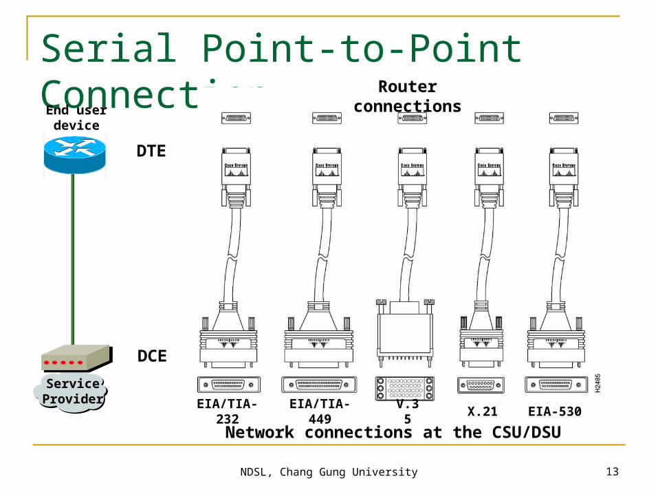
Serial Point-to-Point Connection
Network connections at the CSU/DSUEIA/TIA-232 EIA/TIA-449 EIA-530V.35 X.21
End user device
Service Provider
DTE
DCE
Router connections

NDSL, Chang Gung University 14
Packet-Switching Networks
Basic technology the same as in the 1970s One of the few effective technologies for long
distance data communications Frame relay and ATM are variants of packet-
switching Advantages:
Flexibility, resource sharing, robust, responsive Disadvantages:
Time delays in distributed networks, overhead penalties
Need for routing and congestion control
NDSL, Chang Gung University 15
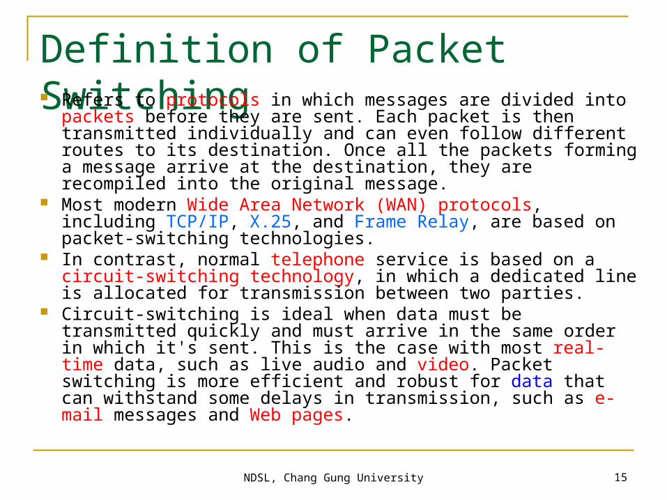
Definition of Packet Switching Refers to protocols in which messages are divided into packets
before they are sent. Each packet is then transmitted individually and can even follow different routes to its destination. Once all the packets forming a message arrive at the destination, they are recompiled into the original message.
Most modern Wide Area Network (WAN) protocols, including TCP/IP, X.25, and Frame Relay, are based on packet-switching technologies.
In contrast, normal telephone service is based on a circuit-switching technology, in which a dedicated line is allocated for transmission between two parties.
Circuit-switching is ideal when data must be transmitted quickly and must arrive in the same order in which it's sent. This is the case with most real-time data, such as live audio and video. Packet switching is more efficient and robust for data that can withstand some delays in transmission, such as e-mail messages and Web pages.

NDSL, Chang Gung University 16
Circuit-Switching
Long-haul telecom network designed for voice
Network resources dedicated to one call Shortcomings when used for data:
Inefficient (high idle time) Constant data rate

NDSL, Chang Gung University 17
Packet-Switching
Data transmitted in short blocks, or packets Packet length < 1000 octets Each packet contains user data plus control
info (routing) Store and forward

NDSL, Chang Gung University 18
The Use of Packets

NDSL, Chang Gung University 19
Packet Switching: Datagram Approach

NDSL, Chang Gung University 20
Advantages with compared to Circuit-Switching Greater line efficiency (many packets can go
over shared link) Data rate conversions Non-blocking under heavy traffic (but
increased delays). When traffic becomes heavy on a circuit-switching network, some calls are blocked.
Priorities can be used.

NDSL, Chang Gung University 21
Disadvantages relative to Circuit-Switching Packets incur additional delay with every
node they pass through Jitter: variation in packet delay Data overhead in every packet for routing
information, etc Processing overhead for every packet at
every node traversed

NDSL, Chang Gung University 22
Simple Switching Network
NDSL, Chang Gung University 23
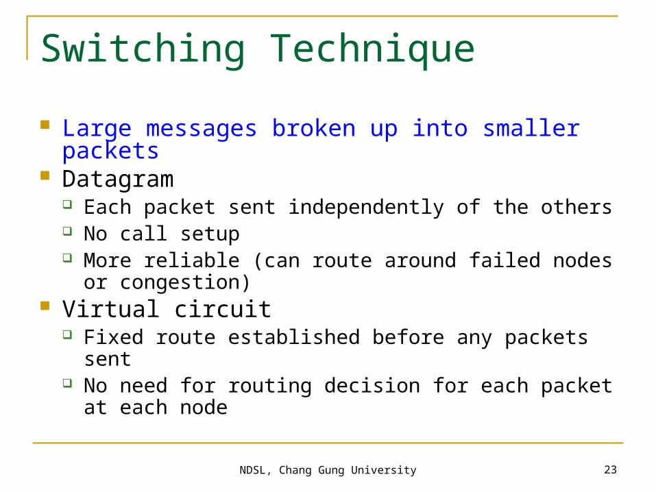
Switching Technique
Large messages broken up into smaller packets Datagram
Each packet sent independently of the others No call setup More reliable (can route around failed nodes or
congestion) Virtual circuit
Fixed route established before any packets sent No need for routing decision for each packet at each
node

NDSL, Chang Gung University 24
Packet Switching: Virtual-Circuit Approach

NDSL, Chang Gung University 25
An Introduction to X.25 The first commercial packet-switching network interface
standard was X.25. X.25 is now seldom used in developed countries but is
still available in many parts of the world (see next page). A popular standard for packet-switching networks. The
X.25 standard was approved by the CCITT (now the ITU-T) in 1976. It defines layers 1, 2, and 3 in the OSI Reference Model.
3 levels Physical level (X.21) Link level: LAPB (Link Access Protocol-Balanced), a
subset of HDLC (High-level Data Link Control) Packet level (provides virtual circuit service)

NDSL, Chang Gung University 26
Vientiane
Ulaanbaatar
Baghdad
Doha
Kuwait
Bahrain
Dhaka
Yangon
Kathmandu
Kabul
Karachi
ColomboMale
Hanoi
Phnom Penh
PyongYang
Ashgabad
Macao
64K
Dushanbe
Almaty
NI
NI
NI
NI
Seoul
NI
NI
14.4-33.6K (V.34)
64K
14.4-33.6K V.34
9.6K
64K
128K
50
50
50
50
50
64K
200
2.4K
64K
100
75
1200
75
50
100
7575
9.6K
Melbourne
Offenbach
Offenbach
Cairo
Cairo
Algiers
Moscow
Kuala Lumpur
Tashkent
Novosibirsk Khabarovsk
Bangkok
Frame RelayCIR<16/16K>
Frame RelayCIR<16/16K>
Melbourne
Washington
Frame RelayCIR<16/16K>
NI
NI 14.4-33.6K (V.34)
14.4-33.6K (V.34)
14.4-33.6K (V.34)
Regional Meteorological Telecommunication Network for Region II (Asia)Current status as of December 2004
Bishkek
64K
2.4K
Singapore
9.6K
RTH in Region II
NMC in Region II
Centre in other region
MTN circuitRegional circuitInterregional circuitAdditional circuit
Non-IP linkIP link
NI No implementation
14.4-33.6K (V.34)
Tehran
Sanaa
200
Hong Kong
Moscow
NIFrame RelayCIR<32/32K>
Tokyo
Beijing
Frame RelayCIR<16/16K>
IMTN-MDCN CIR<32/768K>
IMTN-MDCNCIR<32/32K>
Manila
IMTN-MDCNFrame RelayCIR<48/48K>
Internet
Jeddah
Internet Internet
Internet
Muscat
Abu-Dhabi
NI
Id V.34
Id V.34
64K
64K
64K
Internet
Washington
Internet
ISDN 128K
14.4-33.6K (V.34)
14.4-33.6K (V.34)
Via Moscow
IMTN-MDCNFrame RelayCIR<48/48K>
14.4-33.6K (V.34)
Frame RelayCIR<16/16K>Internet
IMTN-MDCNFrame RelayCIR<16/16K>
IMTN-MDCNFrame RelayCIR<8/8K>
IMTN-MDCNFrame RelayCIR<16/8K>
CMA-VSATCMA-VSAT
CMA-VSAT
64K
64K
64K
Thimpu
New Delhi
NI
64K
64K
NDSL, Chang Gung University 27
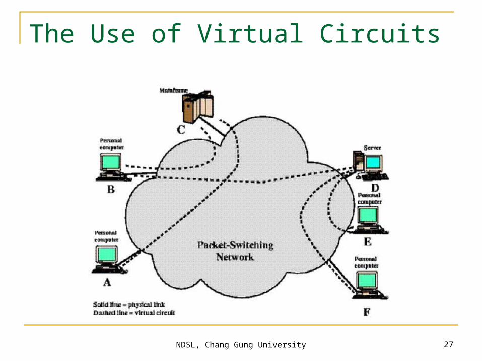
The Use of Virtual Circuits

NDSL, Chang Gung University 28
User Data and X.25 Protocol Control Information
User data
Layer 3header
LAPBheader
LAPBtrailer
X.25 packet
LAPB frame

NDSL, Chang Gung University 29
Frame Relay Networks
Designed to eliminate much of the overhead in X.25
Call control signaling on separate logical connection from user data
Multiplexing/switching of logical connections at layer 2 (not layer 3)
No hop-by-hop flow control and error control Throughput an order of magnitude higher than
X.25

NDSL, Chang Gung University 30
Comparison of X.25 and Frame Relay Protocol Stacks
X.25 packetlevel
LAPB
PHY layer
Implemented byend system and
network
PHY layer
Implemented byend system but
not network
PHY layer
Implemented byend system but
not network
LAPF control
LAPF core
LAPF control
Implementedby end systemand network
Implemented byend system and
network
(a) X.25 (b) Frame relay (c) Frame switching
LAPF core

NDSL, Chang Gung University 31
Virtual Circuits and Frame Relay Virtual Connections
NDSL, Chang Gung University 32
Frame Relay Architecture
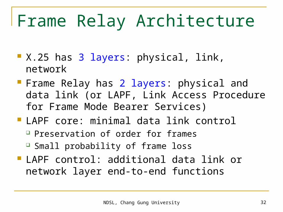
X.25 has 3 layers: physical, link, network Frame Relay has 2 layers: physical and data
link (or LAPF, Link Access Procedure for Frame Mode Bearer Services)
LAPF core: minimal data link control Preservation of order for frames Small probability of frame loss
LAPF control: additional data link or network layer end-to-end functions

NDSL, Chang Gung University 33
Outline
Describe the Introduction Describe the history of Frame Relay Describe how Frame Relay works Describe the primary functionality traits of
Frame Relay Describe the format of Frame Relay frames

NDSL, Chang Gung University 34
Frame Relay Virtual Circuits
Frame Relay provides connection-oriented data link layer communications. This means that a defined communication exists between each pair of devices and that these connections are associated with a connection identifier (ID).
This service is implemented by using a FR virtual circuit, which is a logical connection created between two DTE devices across a Frame Relay packet-switched network (PSN).
Virtual circuits provide a bidirectional communication path from one DTE device to another and are uniquely identified by a data-link connection identifier (DLCI).
NDSL, Chang Gung University 35
Frame Relay Virtual Circuits (cont.) A number of virtual circuits can be multiplexed into a
single physical circuit for transmission across the network.
This capability often can reduce the equipment and network complexity required to connect multiple DTE devices.
A virtual circuit can pass through any number of intermediate DCE devices (switches) located within the Frame Relay PSN.
Frame Relay virtual circuits fall into two categories: switched virtual circuits (SVCs) and permanent virtual circuits (PVCs).

NDSL, Chang Gung University 36
Switched Virtual Circuits (SVCs) Switched virtual circuits (SVCs) are temporary connections used
in situations requiring only sporadic data transfer between DTE devices across the Frame Relay network. A communication session across an SVC consists of the following four operational states: Call setup—The virtual circuit between two Frame Relay DTE
devices is established. Data transfer—Data is transmitted between the DTE devices
over the virtual circuit. Idle—The connection between DTE devices is still active, but no
data is transferred. If an SVC remains in an idle state for a defined period of time, the call can be terminated.
Call termination—The virtual circuit between DTE devices is terminated.

NDSL, Chang Gung University 37
Permanent Virtual Circuits (PVCs) Permanent virtual circuits (PVCs) are permanently established
connections that are used for frequent and consistent data transfers between DTE devices across the Frame Relay network. Communication across a PVC does not require the call setup and termination states that are used with SVCs. PVCs always operate in one of the following two operational states:
Data transfer—Data is transmitted between the DTE devices over the virtual circuit.
Idle—The connection between DTE devices is active, but no data is transferred. Unlike SVCs, PVCs will not be terminated under any circumstances when in an idle state.
DTE devices can begin transferring data whenever they are ready because the circuit is permanently established.

NDSL, Chang Gung University 38
Data-Link Connection Identifier Frame Relay virtual circuits are identified by data-link
connection identifiers (DLCIs). DLCI values typically are assigned by the Frame Relay service provider (for example, the telephone company).
Frame Relay DLCIs have local significance, which means that their values are unique in the LAN, but not necessarily in the Frame Relay WAN.
NDSL, Chang Gung University 39
Congestion-Control Mechanisms Frame Relay reduces network overhead by
implementing simple congestion-notification mechanisms rather than explicit, per-virtual-circuit flow control.
Frame Relay typically is implemented on reliable network media, so data integrity is not sacrificed because flow control can be left to higher-layer protocols. Frame Relay implements two congestion-notification mechanisms: Forward-explicit congestion notification (FECN) Backward-explicit congestion notification (BECN)

NDSL, Chang Gung University 40
Congestion-Control Mechanisms FECN and BECN each is controlled by a single bit contained in
the Frame Relay frame header. The Frame Relay frame header also contains a Discard Eligibility (DE) bit, which is used to identify less important traffic that can be dropped during periods of congestion.
The FECN bit is part of the Address field in the Frame Relay frame header.
The FECN mechanism is initiated when a DTE device sends Frame Relay frames into the network. If the network is congested, DCE devices (switches) set the value of the frames’ FECN bit to 1.
When the frames reach the destination DTE device, the Address field (with the FECN bit set) indicates that the frame experienced congestion in the path from source to destination.
The DTE device can relay this information to a higher-layer protocol for processing.
Depending on the implementation, flow control may be initiated, or the indication may be ignored.

NDSL, Chang Gung University 41
Congestion-Control Mechanisms The BECN bit is part of the Address field in the
Frame Relay frame header. DCE devices set the value of the BECN bit to 1 in
frames traveling in the opposite direction of frames with their FECN bit set.
This informs the receiving DTE device that a particular path through the network is congested.
The DTE device then can relay this information to a higher-layer protocol for processing.
Depending on the implementation, flow-control may be initiated, or the indication may be ignored.
NDSL, Chang Gung University 42
Frame Relay Discard Eligibility The Discard Eligibility (DE) bit is used to indicate
that a frame has lower importance than other frames. The DE bit is part of the Address field in the Frame Relay frame header.
DTE devices can set the value of the DE bit of a frame to 1 to indicate that the frame has lower importance than other frames.
When the network becomes congested, DCE devices will discard frames with the DE bit set before discarding those that do not. This reduces the likelihood of critical data being dropped by Frame Relay DCE devices during periods of congestion.

NDSL, Chang Gung University 43
Frame Relay Error Checking
Frame Relay uses a common error-checking mechanism known as the cyclic redundancy check (CRC).
The CRC compares two calculated values to determine whether errors occurred during the transmission from source to destination.
Frame Relay reduces network overhead by implementing error checking rather than error correction.
Frame Relay typically is implemented on reliable network media, so data integrity is not sacrificed because error correction can be left to higher-layer protocols running on top of Frame Relay.

NDSL, Chang Gung University 44
Frame Relay Local Management Interface The Local Management Interface (LMI) is a set of enhancements
to the basic Frame Relay specification. The LMI was developed in 1990 by Cisco Systems, StrataCom,
Northern Telecom, and Digital Equipment Corporation. It offers a number of features (called extensions) for managing
complex internetworks. Key Frame Relay LMI extensions include global addressing, virtual circuit status messages, and multicasting.
The LMI global addressing extension gives Frame Relay data-link connection identifier (DLCI) values global rather than local significance.
DLCI values become DTE addresses that are unique in the Frame Relay WAN. The global addressing extension adds functionality and manageability to Frame Relay internetworks.

NDSL, Chang Gung University 45
Frame Relay Local Management Interface (cont.) Individual network interfaces and the end nodes attached to
them, for example, can be identified by using standard address-resolution and discovery techniques. In addition, the entire Frame Relay network appears to be a typical LAN to routers on its periphery.
LMI virtual circuit status messages provide communication and synchronization between Frame Relay DTE and DCE devices.
These messages are used to periodically report on the status of PVCs, which prevents data from being sent into black holes (that is, over PVCs that no longer exist).
The LMI multicasting extension allows multicast groups to be assigned. Multicasting saves bandwidth by allowing routing updates and address-resolution messages to be sent only to specific groups of routers. The extension also transmits reports on the status of multicast groups in update messages.

NDSL, Chang Gung University 46
Frame Relay Network Implementation A common private Frame
Relay network implementation is to equip a T1 multiplexer with both Frame Relay and non-Frame Relay interfaces.
Frame Relay traffic is forwarded out the Frame Relay interface and onto the data network. Non-Frame Relay traffic is forwarded to the appropriate application or service, such as a private branch exchange (PBX) for telephone service or to a video-teleconferencing application.
NDSL, Chang Gung University 47
Frame Relay Network Implementation Frame Relay is implemented in both public carrier-provided
networks and in private enterprise networks. Public Carrier-Provided Networks
In public carrier-provided Frame Relay networks, the Frame Relay switching equipment is located in the central offices of a telecommunications carrier. Subscribers are charged based on their network use but are relieved from administering and maintaining the Frame Relay network equipment and service.
Generally, the DCE equipment also is owned by the telecommunications provider.
DTE equipment either will be customer-owned or perhaps will be owned by the telecommunications provider as a service to the customer.
Private Enterprise Networks More frequently, organizations worldwide are deploying private Frame
Relay networks. In private Frame Relay networks, the administration and maintenance of the network are the responsibilities of the enterprise (a private company). All the equipment, including the switching equipment, is owned by the customer.

NDSL, Chang Gung University 48
Outline
Describe the Introduction Describe the history of Frame Relay Describe how Frame Relay works Describe the primary functionality traits of
Frame Relay Describe the format of Frame Relay frames

NDSL, Chang Gung University 49
Frame Relay Frame Formats Flags—Delimits the beginning and end of the frame.
The value of this field is always the same and is represented either as the hexadecimal number 7E or as the binary number 01111110.
Address—Contains the following information: (in bits) DLCI: ‘0’ for Call Control message Extended Address (EA): Address field extension bit C/R: the C/R bit is not currently defined. Congestion Control:

NDSL, Chang Gung University 50
LAPF Core
LAPF (Link Access Procedure for Frame Mode Bearer Services)
Frame delimiting, alignment and transparency
Frame multiplexing/demultiplexing Inspection of frame for length constraints Detection of transmission errors Congestion control

NDSL, Chang Gung University 51
LAPF-core Formats
Upper DLCI
Lower DLCI FECN BECN
C/R EA 08 7 6 5 4 3 2 1
(a) Address field - 2 octets (default)
DE EA 1
Upper DLCI
DLCI FECN BECN
C/R EA 08 7 6 5 4 3 2 1
(b) Address field - 3 octets
DE EA 0
Lower DLCI or DL-CORE control D/C EA 1
Upper DLCI
DLCI FECN BECN
C/R EA 08 7 6 5 4 3 2 1
(c) Address field - 4 octets
DE EA 0
DLCI EA 0
Lower DLCI or DL-CORE control D/C EA 1
EA Address field extention bitC/R Command/response bitFECN Forward explicit congestion notificationBECN Backward explict congestion notificationDLCI Data link connection identifierD/C DLCI or DL-CORE control indicatorDE Dsicard eligibility

NDSL, Chang Gung University 52
User Data Transfer
No control field, which is normally used for: Identify frame type (data or control) Sequence numbers
Implication: Connection setup/teardown carried on separate
channel Cannot do flow and error control
NDSL, Chang Gung University 53
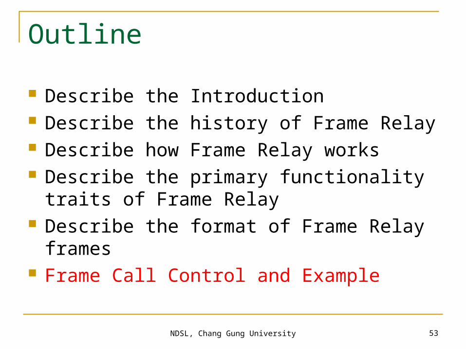
Outline
Describe the Introduction Describe the history of Frame Relay Describe how Frame Relay works Describe the primary functionality traits of
Frame Relay Describe the format of Frame Relay frames Frame Call Control and Example

NDSL, Chang Gung University 54
Frame Relay Call Control
Frame Relay Call Control Data transfer involves:
Establish logical connection and DLCI Exchange data frames Release logical connection

NDSL, Chang Gung University 55
Frame Relay Call Control
4 message types needed SETUP CONNECT RELEASE RELEASE COMPLETE

NDSL, Chang Gung University
Frame Relay Overview
Virtual circuits make connections Connection-oriented service
Frame Relay works here.
DCE or FrameRelay Switch
CSU/DSU

NDSL, Chang Gung University 57
Frame Relay Stack
OSI Reference Model Frame Relay
Physical
Presentation
Session
Transport
Network
Data Link
Application
EIA/TIA-232, EIA/TIA-449, V.35, X.21, EIA/TIA-530
Frame Relay
IP/IPX/AppleTalk, etc.

NDSL, Chang Gung University
Frame Relay Terminology
LocalAccess
Loop=T1
Local AccessLoop=64 kbps
Local AccessLoop=64 kbps
DLCI: 400
PVC
DLCI: 500
LMI100=Active400=Active
LMI100=Active400=Active
DLCI: 200
DLCI: 100PVC

NDSL, Chang Gung University
CSU/DSU
Frame RelayAddress Mapping
Get locally significant DLCIs from provider Map your network addresses to DLCIs
DLCI: 500 PVC 10.1.1.1
Inverse ARP orFrame Relay map
IP(10.1.1.1)
FrameRelay DLCI (500)

NDSL, Chang Gung University
Frame Relay Signaling
Cisco supports three LMI standards: Cisco ANSI T1.617 ITU-T Q.933
DLCI: 400PVC
Keepalive
CSU/DSU
DLCI: 500 PVC 10.1.1.1
xLMI500=Active400=Inactive
LMI500=Active400=Inactive
NDSL, Chang Gung University
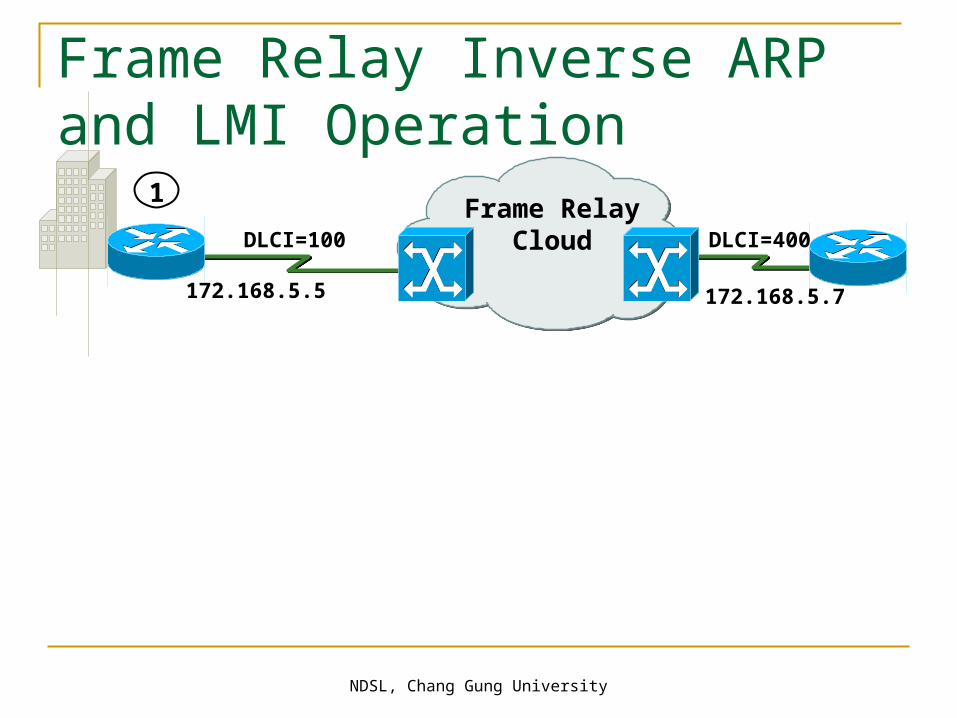
Frame Relay Inverse ARP and LMI Operation
Frame RelayCloud
1
DLCI=100 DLCI=400
172.168.5.5 172.168.5.7

NDSL, Chang Gung University
Frame Relay Inverse ARP and LMI Operation
2 Status Inquiry 2Status Inquiry
Frame RelayCloud
1
DLCI=100 DLCI=400
172.168.5.5 172.168.5.7

NDSL, Chang Gung University
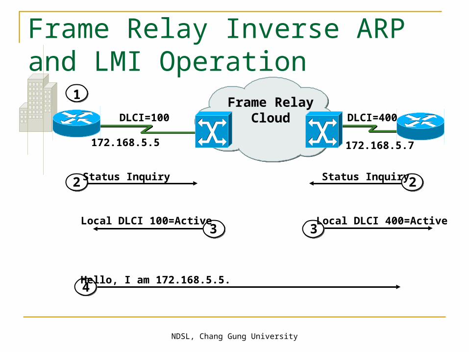
Frame Relay Inverse ARP and LMI Operation
3Local DLCI 100=Active
4Local DLCI 400=Active
2 Status Inquiry 2Status Inquiry
Frame RelayCloud
1
DLCI=100 DLCI=400
3
172.168.5.5 172.168.5.7
NDSL, Chang Gung University
Frame Relay Inverse ARP and LMI Operation
4Hello, I am 172.168.5.5.
3Local DLCI 100=Active
4Local DLCI 400=Active
2 Status Inquiry 2Status Inquiry
Frame RelayCloud
1
DLCI=100 DLCI=400
3
172.168.5.5 172.168.5.7
NDSL, Chang Gung University
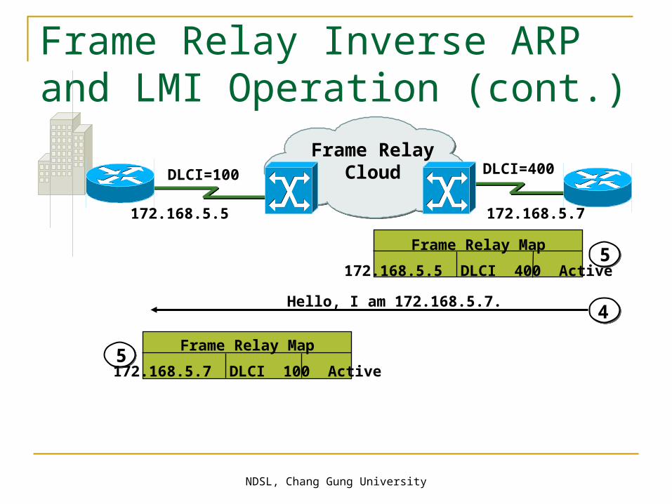
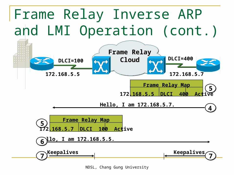
Frame Relay Inverse ARP and LMI Operation (cont.)
Hello, I am 172.168.5.7.4
5Frame Relay Map
172.168.5.5 DLCI 400 Active
Frame RelayCloudDLCI=100 DLCI=400
Frame Relay Map
172.168.5.7 DLCI 100 Active5
172.168.5.5 172.168.5.7

NDSL, Chang Gung University
Frame Relay Inverse ARP and LMI Operation (cont.)
Hello, I am 172.168.5.7.4
5Frame Relay Map
172.168.5.5 DLCI 400 Active
Frame RelayCloudDLCI=100 DLCI=400
Frame Relay Map
172.168.5.7 DLCI 100 Active5
Hello, I am 172.168.5.5.6
172.168.5.5 172.168.5.7
NDSL, Chang Gung University
Frame Relay Inverse ARP and LMI Operation (cont.)
Keepalives Keepalives
Hello, I am 172.168.5.7.4
5Frame Relay Map
172.168.5.5 DLCI 400 Active
Frame RelayCloudDLCI=100 DLCI=400
Frame Relay Map
172.168.5.7 DLCI 100 Active5
Hello, I am 172.168.5.5.6
7 7
172.168.5.5 172.168.5.7

NDSL, Chang Gung University
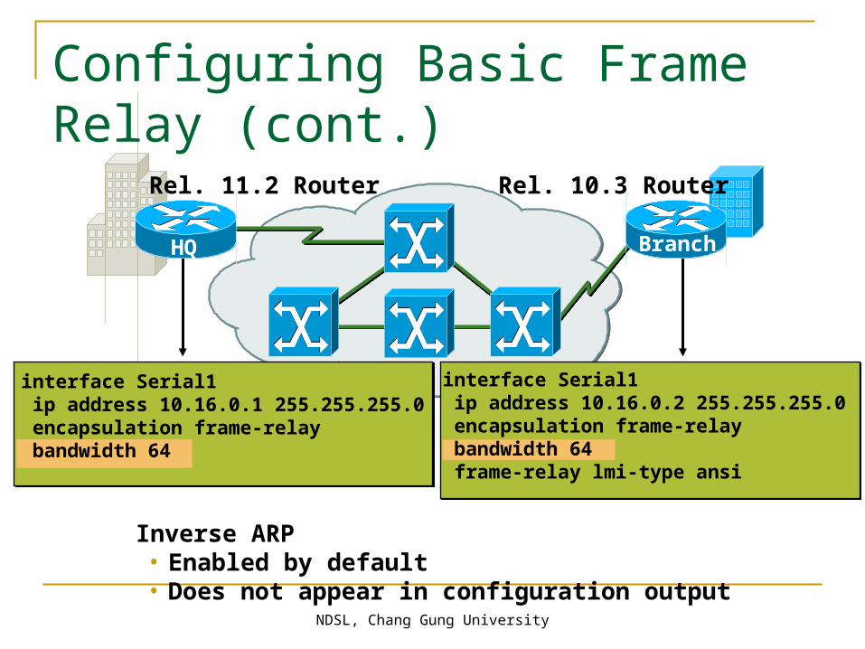
Rel. 11.2 Router Rel. 10.3 Router
interface Serial1 ip address 10.16.0.1 255.255.255.0 encapsulation frame-relay bandwidth 64
interface Serial1 ip address 10.16.0.2 255.255.255.0 encapsulation frame-relay bandwidth 64 frame-relay lmi-type ansi
HQ Branch
Configuring Basic Frame Relay
NDSL, Chang Gung University
Inverse ARP• Enabled by default• Does not appear in configuration output
Rel. 11.2 Router Rel. 10.3 Router
HQ
interface Serial1 ip address 10.16.0.1 255.255.255.0 encapsulation frame-relay bandwidth 64
interface Serial1 ip address 10.16.0.2 255.255.255.0 encapsulation frame-relay bandwidth 64 frame-relay lmi-type ansi
Branch
Configuring Basic Frame Relay (cont.)

NDSL, Chang Gung University
DLCI=110IP address=10.16.0.1/24
p1r1
DLCI=100IP address=10.16.0.2/24
interface Serial1ip address 10.16.0.1 255.255.255.0encapsulation frame-relaybandwidth 64frame-relay map ip 10.16.0.2 110 broadcast
HQ Branch
Configuring a Static Frame Relay Map
NDSL, Chang Gung University
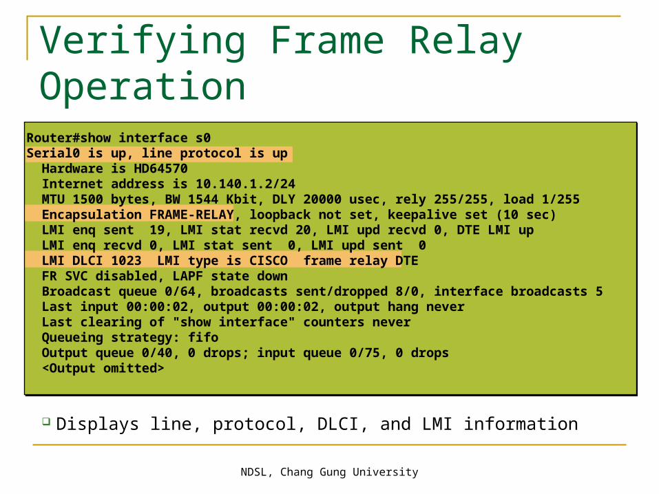
Verifying Frame Relay Operation
Displays line, protocol, DLCI, and LMI information
Router#show interface s0Serial0 is up, line protocol is up Hardware is HD64570 Internet address is 10.140.1.2/24 MTU 1500 bytes, BW 1544 Kbit, DLY 20000 usec, rely 255/255, load 1/255 Encapsulation FRAME-RELAY, loopback not set, keepalive set (10 sec) LMI enq sent 19, LMI stat recvd 20, LMI upd recvd 0, DTE LMI up LMI enq recvd 0, LMI stat sent 0, LMI upd sent 0 LMI DLCI 1023 LMI type is CISCO frame relay DTE FR SVC disabled, LAPF state down Broadcast queue 0/64, broadcasts sent/dropped 8/0, interface broadcasts 5 Last input 00:00:02, output 00:00:02, output hang never Last clearing of "show interface" counters never Queueing strategy: fifo Output queue 0/40, 0 drops; input queue 0/75, 0 drops <Output omitted>

NDSL, Chang Gung University
Displays LMI information
Router#show frame-relay lmi LMI Statistics for interface Serial0 (Frame Relay DTE) LMI TYPE = CISCO Invalid Unnumbered info 0 Invalid Prot Disc 0 Invalid dummy Call Ref 0 Invalid Msg Type 0 Invalid Status Message 0 Invalid Lock Shift 0 Invalid Information ID 0 Invalid Report IE Len 0 Invalid Report Request 0 Invalid Keep IE Len 0 Num Status Enq. Sent 113100 Num Status msgs Rcvd 113100 Num Update Status Rcvd 0 Num Status Timeouts 0
Verifying Frame Relay Operation (cont.)Verifying Frame Relay Operation (cont.)
NDSL, Chang Gung University
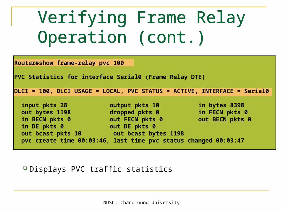
Displays PVC traffic statistics
Verifying Frame Relay Operation (cont.)Verifying Frame Relay Operation (cont.)
Router#show frame-relay pvc 100
PVC Statistics for interface Serial0 (Frame Relay DTE)
DLCI = 100, DLCI USAGE = LOCAL, PVC STATUS = ACTIVE, INTERFACE = Serial0
input pkts 28 output pkts 10 in bytes 8398 out bytes 1198 dropped pkts 0 in FECN pkts 0 in BECN pkts 0 out FECN pkts 0 out BECN pkts 0 in DE pkts 0 out DE pkts 0 out bcast pkts 10 out bcast bytes 1198 pvc create time 00:03:46, last time pvc status changed 00:03:47

NDSL, Chang Gung University
Displays the route maps, either static or dynamic
Router#show frame-relay mapSerial0 (up): ip 10.140.1.1 dlci 100(0x64,0x1840), dynamic, broadcast,, status defined, active
Verifying Frame Relay Operation (cont.)Verifying Frame Relay Operation (cont.)

NDSL, Chang Gung University 75
• Clears dynamically created Frame Relay maps
Verifying Frame Relay Operation (cont.)
Router#show frame-relay mapSerial0 (up): ip 10.140.1.1 dlci 100(0x64,0x1840), dynamic, broadcast,, status defined, activeRouter#clear frame-relay-inarpRouter#sh frame mapRouter#
NDSL, Chang Gung University 76
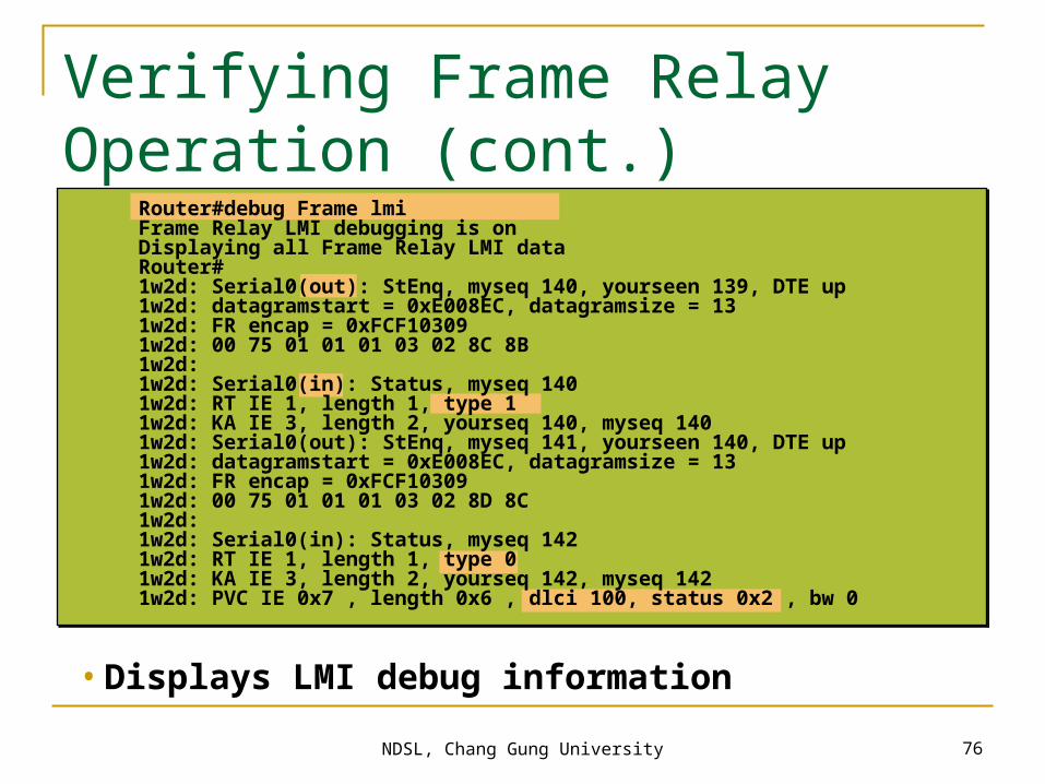
• Displays LMI debug information
Verifying Frame Relay Operation (cont.)
Router#debug Frame lmiFrame Relay LMI debugging is onDisplaying all Frame Relay LMI dataRouter#1w2d: Serial0(out): StEnq, myseq 140, yourseen 139, DTE up1w2d: datagramstart = 0xE008EC, datagramsize = 131w2d: FR encap = 0xFCF103091w2d: 00 75 01 01 01 03 02 8C 8B1w2d:1w2d: Serial0(in): Status, myseq 1401w2d: RT IE 1, length 1, type 11w2d: KA IE 3, length 2, yourseq 140, myseq 1401w2d: Serial0(out): StEnq, myseq 141, yourseen 140, DTE up1w2d: datagramstart = 0xE008EC, datagramsize = 131w2d: FR encap = 0xFCF103091w2d: 00 75 01 01 01 03 02 8D 8C1w2d:1w2d: Serial0(in): Status, myseq 1421w2d: RT IE 1, length 1, type 01w2d: KA IE 3, length 2, yourseq 142, myseq 1421w2d: PVC IE 0x7 , length 0x6 , dlci 100, status 0x2 , bw 0

NDSL, Chang Gung University
Star (Hub and Spoke)
Full Mesh
Partial Mesh
Frame Relay default: nonbroadcast, multiaccess (NBMA)
Selecting a Frame Relay Topology
NDSL, Chang Gung University
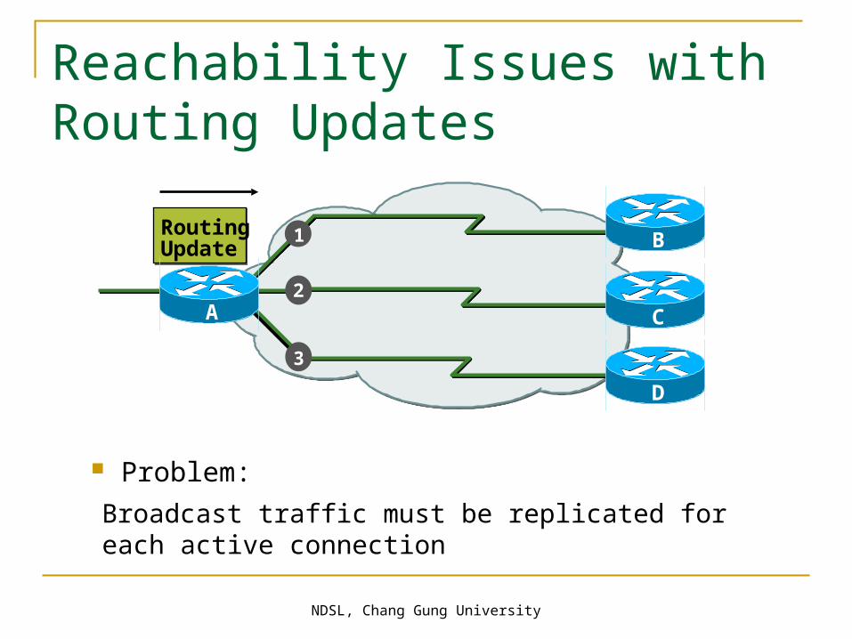
Problem:
Broadcast traffic must be replicated for each active connection
RoutingUpdate
A C
B
2
3
1
Reachability Issues with Routing Updates
B
C
D
A
NDSL, Chang Gung University
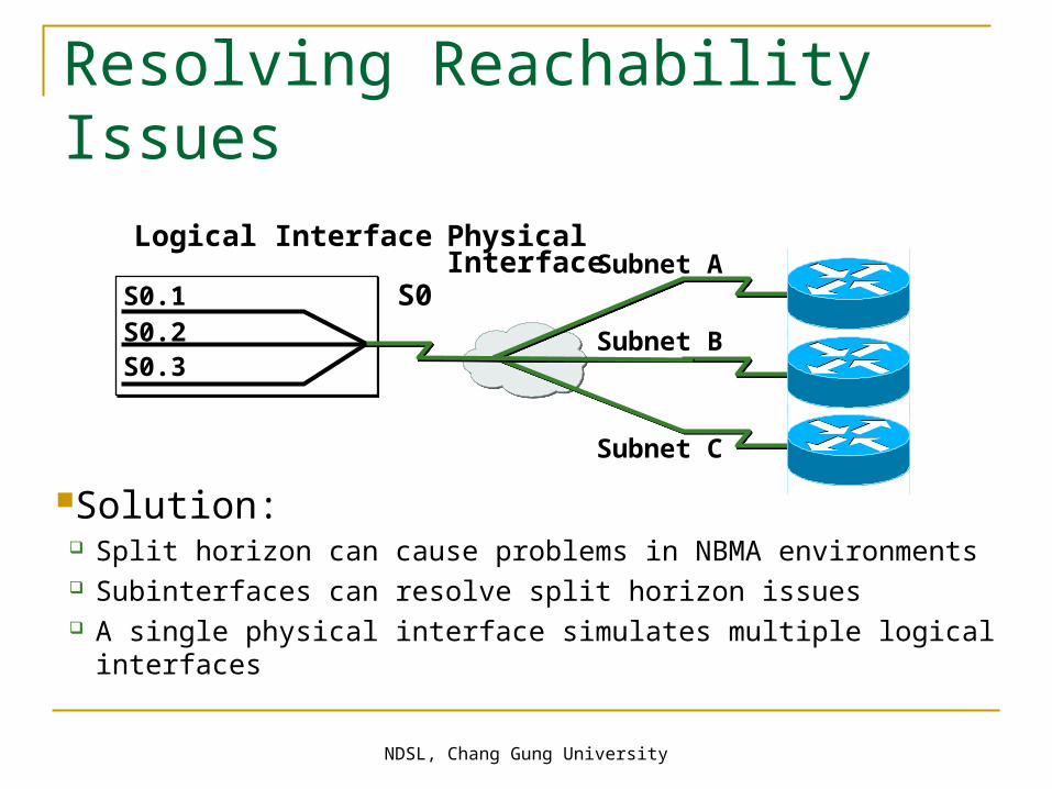
Resolving Reachability Issues
Solution: Split horizon can cause problems in NBMA environments Subinterfaces can resolve split horizon issues A single physical interface simulates multiple logical interfaces
Subnet A
Subnet B
Subnet C
S0
PhysicalInterface
S0.1S0.2S0.3
Logical Interface

NDSL, Chang Gung University
Configuring Subinterfaces
Point-to-Point– Subinterfaces act as leased line – Each point-to-point subinterface requires its own subnet – Applicable to hub and spoke topologies
• Multipoint– Subinterfaces act as NBMA network so they do not resolve the split
horizon issue– Can save address space because uses single subnet– Applicable to partial-mesh and full-mesh topology

NDSL, Chang Gung University
A
10.17.0.1s0.2
B
Configuring Point-to-Point Subinterfaces
interface Serial0 no ip address encapsulation frame-relay!interface Serial0.2 point-to-point ip address 10.17.0.1 255.255.255.0 bandwidth 64 frame-relay interface-dlci 110!interface Serial0.3 point-to-point ip address 10.18.0.1 255.255.255.0 bandwidth 64 frame-relay interface-dlci 120!
s0.310.18.0.1
C
10.17.0.2
10.18.0.2
DLCI=110
DLCI=120
NDSL, Chang Gung University
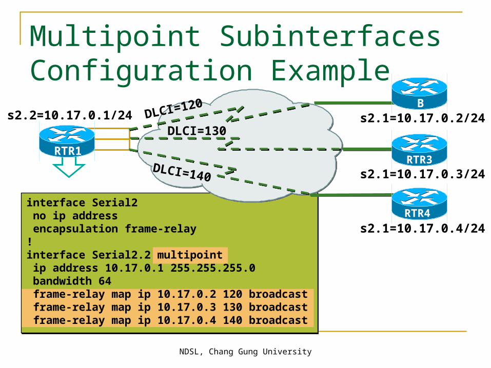
interface Serial2 no ip address encapsulation frame-relay!interface Serial2.2 multipoint ip address 10.17.0.1 255.255.255.0 bandwidth 64 frame-relay map ip 10.17.0.2 120 broadcast frame-relay map ip 10.17.0.3 130 broadcast frame-relay map ip 10.17.0.4 140 broadcast
s2.1=10.17.0.2/24s2.2=10.17.0.1/24
s2.1=10.17.0.4/24
s2.1=10.17.0.3/24
RTR1
B
RTR3
RTR4
Multipoint Subinterfaces Configuration Example
DLCI=120
DLCI=130
DLCI=140

NDSL, Chang Gung University 83
Visual Objective
pod ro’s s0A 10.140.1.2B 10.140.2.2C 10.140.3.2D 10.140.4.2E 10.140.5.2F 10.140.6.2G 10.140.7.2H 10.140.8.2I 10.140.9.2J 10.140.10.2K 10.140.11.2L 10.140.12.2
core_ server10.1.1.1
wg_sw_a10.2.2.11
wg_sw_l10.13.13.11
wg_pc_a10.2.2.12
wg_pc_l10.13.13.12
wg_ro_ae0/1 e0/2
e0/2e0/1
e0
e0
fa0/23
core_sw_a10.1.1.2
wg_ro_l
core_ro10.1.1.3
fa0/24 fa0/0
FR
...
10.13.13.3
PPP with CHAP
Frame Relay
10.2.2.3s010.140.1.2/24
s0
10.140.12.2/24
s2/7.x10.140.1.1/24 … 10.140.12.1/24

NDSL, Chang Gung University 84
1. What is a DLCI?
2. What are two methods to map a network layer address to a DLCI on a Cisco router?
3. What are the advantages of configuring Frame Relay subinterfaces?
Review Questions