Embed Size (px)
Citation preview
2nd Reading
March 9, 2013 12:17 WSPC/0219-8762 196-IJCM 1350008
International Journal of Computational MethodsVol. 10, No. 4 (2013) 1350008 (24 pages)c© World Scientific Publishing CompanyDOI: 10.1142/S0219876213500084
SPECIAL CIRCULAR HOLE ELEMENTS FOR THERMALANALYSIS IN CELLULAR SOLIDS WITH MULTIPLE
CIRCULAR HOLES
QING HUA QIN∗ and HUI WANG
College of Civil Engineering and ArchitectureHenan University of TechnologyZhengzhou, 450001, P. R. China
Received 16 August 2011Accepted 28 December 2011Published 12 March 2013
This paper presents a new hybrid finite element approach with fundamental solutions(HFS-FEM) as a trial function for modeling thermal behavior in perforated or cellu-lar solids containing multiple randomly distributed circular holes with arbitrary sizesand locations, using special elements to reduce mesh effort. Based on the independentintra-element field in the element consisting of fundamental solutions and the framefield defined on the element boundary, the approach has characteristic features of ele-mentary boundary integrals and versatile element construction by virtue of combiningthe new hybrid functional. Special purpose hole elements and regular elements are con-structed using the special fundamental solution satisfying the specified hole boundaryconditions and the conventional fundamental solution, respectively, such that the cir-cular hole region can be modeled with a much smaller number of elements. Numericalexamples including problems with single, double and randomly distributed multiple holesare considered and the results demonstrate the versatility, accuracy, and efficiency of theapproach presented.
Keywords: Heat conduction; hybrid finite element; fundamental solutions; special circularhole element; cellular solids.
1. Introduction
Cellular solids like honeycombs, foams, cancellous bone, etc., are of considerableinterest in engineering applications due to their superior thermal and mechanicalperformance. Generally, cellular materials in service may experience a considerablerange of operating temperature and mechanical conditions. The presence of mul-tiple holes and the interactions among them have significant effects on the overallthermal behavior as well as the mechanical properties of this class of materials, and
∗Corresponding author.
1350008-1
Int.
J. C
ompu
t. M
etho
ds D
ownl
oade
d fr
om w
ww
.wor
ldsc
ient
ific
.com
by 5
8.16
9.42
.243
on
03/2
0/13
. For
per
sona
l use
onl
y.

2nd Reading
March 9, 2013 12:17 WSPC/0219-8762 196-IJCM 1350008
Q. H. Qin & H. Wang
thus need to be taken into account in detail. Because of the geometrical complexity,a number of numerical methods have been developed over past decades for solvingproblems involving multiple circular holes in an infinite or finite solid. For instance,Mogilevskaya and Crouch employed the Galerkin boundary integral method for ana-lyzing multiple circular inclusions with perfect or imperfect interfaces [Mogilevskayaand Crouch (2001, 2002)]; Duan et al. [1986] combined the direct boundary inte-gral method with truncated complex series expansions to treat problems involvingcircular holes, and found that the asymptotic behavior for hole-to-hole interactionswas similar to that of stress behavior near a crack tip, and that the convectionalboundary element method (BEM) [Qin (1993)] was not effective in capturing thisbehavior. Chen et al. developed a semi-analytical null-field boundary integral equa-tion approach for torsion analysis of circular inclusions [Chen and Lee (2009)] andelliptical inclusions [Chen et al. (2010)], using the series form of fundamental solu-tion in the polar coordinate [Chen and Wu (2006)]. Additionally, the alternativemethod [Ting et al. (1999)], indirect BEM [Lee et al. (2007)] and the complexboundary integral equation with a fast multipole technique [Helsing and Jonsson(2001)] or series expansion technique [Dejoie et al. (2006); Wang et al. (2003)] werealso developed to treat large-scale problems with multiple holes of arbitrary shapesin an infinite plane, half plane and circular plate, respectively.
Compared to the boundary-type methods discussed above, which are usuallybased on boundary discretization and are difficult to solve in problems involv-ing multiple materials, domain-type methods, in which the domain modeled byfinite cells or elements does not involve any singular or hyper-singular integrals thatappear in boundary-type methods, are more feasible in multi-component materialsdue to the material properties being defined in each element only. Among domain-type methods, the traditional finite element method (FEM) based on a suitablepolynomial interpolation [Martin and Carey (1973)] usually needs refined meshesnear the holes to achieve the desired accuracy. To tackle this drawback, the hybridTrefftz finite element method (HT-FEM), combining the advantages of FEM andBEM has been developed to solve such problems [Dhanasekar et al. (2006); Pilt-ner (2008); Qin (1995, 2003); Qin and Diao (1996); Qin and Wang (2009); Wanget al. (2007)]. In contrast to conventional FEM and BEM, the HT-FEM is a hybridmethod which includes the use of an independent auxiliary frame field defined oneach element boundary and an intra-element field chosen so as to a priori satisfythe homogeneous governing differential equations by means of a suitable truncatedcomplete function sets, which can be obtained by virtual of the degenerate ker-nels in series form of fundamental solutions, as demonstrated by Chen et al. [2007].Inter-element continuity is enforced by using a modified variational principle, whichis used to construct the standard force–displacement relationship, that is, stiffnessequation, and to establish linkage of the frame field and the internal field of theelement. The property of nonsingular element boundary integral appearing in HT-FEM enables us to construct arbitrary shaped elements conveniently; however, theterms of truncated T-complete functions must be carefully selected to achieve the
1350008-2
Int.
J. C
ompu
t. M
etho
ds D
ownl
oade
d fr
om w
ww
.wor
ldsc
ient
ific
.com
by 5
8.16
9.42
.243
on
03/2
0/13
. For
per
sona
l use
onl
y.

2nd Reading
March 9, 2013 12:17 WSPC/0219-8762 196-IJCM 1350008
Special Circular Hole Elements for Thermal Analysis
desired results, and it is difficult to generate T-complete functions for certain com-plex or new physical problems. Further, a coordinate transformation is required tokeep the system matrix stable in HT-FEM, and the necessary variational functionalis somewhat complex for practical use.
To address these drawbacks of HT-FEM, a novel hybrid finite formulation basedon the fundamental solution, called HFS-FEM, was originally developed by Wangand Qin for solving two-dimensional linear or nonlinear heat conduction problems[Wang and Qin (2009, 2010a)], effective thermal property of fiber-reinforced com-posites using special elements [Wang and Qin (2011a)] and isotropic elastic [Wangand Qin (2010b)], orthotropic elastic [Wang and Qin (2011b)], functionally gradedelastic [Wang and Qin (2012)] problems with special elements. In the analysis, alinear combination of the fundamental solution at different source points is usedto approximate the field variable within the element. The independent frame fielddefined along the element boundary and the newly developed variational functionalare employed to guarantee inter-element continuity, generate the final stiffness equa-tion and establish a linkage between the boundary frame field and the internal fieldin the element. The proposed HFS-FEM inherits all the advantages of HT-FEMand obviates the difficulties that occur in HT-FEM, and thus has wider applica-bility than HT-FEM. However, the presented HFS-FEM is ineffective for handlingproblems with multiple holes, if the general hybrid element is just used.
In the work described here, we begin with the basic equation of HFS-FEMand apply it to solve heat conduction problems in cellular solids with multiplecircular holes of arbitrary sizes and locations, by introducing three types of specialcircular hole elements. Then, independent intra-element and frame fields as well as amodified variational functional are constructed to yield final solution equations anddetermine all unknowns. The validity of the present work is verified by analyzingseveral problems with multiple circular holes of different sizes and arrangements,and the interactions among circular holes are studied in detail. To demonstrate thenumerical accuracy, the results are compared with those from ABAQUS.
The paper is arranged as follows. It begins with a simple description of theheat conduction model, and corresponding fundamental solutions are provided inSec. 2. Then, a solution procedure for the presented HFS-FEM is described in Sec. 3,providing an initial insight into this new finite element model, and three practicaltypes of special circular hole elements are constructed in Sec. 4. Several numericalexamples are presented in Sec. 5 to validate the proposed algorithm, and concludingremarks are presented in Sec. 6.
2. Statement of Heat Conduction Problems
2.1. Mathematic models
Consider that we are seeking to find the solution of a well-posed heat conductionproblem in a cellular plane domain Ω (Fig. 1) measured in a global coordinate
1350008-3
Int.
J. C
ompu
t. M
etho
ds D
ownl
oade
d fr
om w
ww
.wor
ldsc
ient
ific
.com
by 5
8.16
9.42
.243
on
03/2
0/13
. For
per
sona
l use
onl
y.

2nd Reading
March 9, 2013 12:17 WSPC/0219-8762 196-IJCM 1350008
Q. H. Qin & H. Wang
Fig. 1. Geometrical definition of cellular solids.
system (X1, X2)
∂
∂X1
(k
∂u(X)∂X1
)+
∂
∂X2
(k
∂u(X)∂X2
)= 0 ∀X ∈ Ω (1)
with the following boundary conditionsu = u on Γu
q = −ku,ini = q on Γq,(2)
where u is the sought temperature field, q the boundary heat flux, X(= (X1, X2))the position vector. ni is the ith component of outward normal vector to the bound-ary Γ = Γu ∪ Γq, and u and q are specified functions on the related boundaries,respectively. The space derivatives are denoted by a comma, i.e. u,i = ∂u/∂Xi,and the subscript i takes values 1 and 2 in our analysis. Additionally, the repeatedsubscript indices stand for the summation convention.
For the sake of convenience, the boundary heat flux is rewritten in matrix form as
q = −kA
[u,1
u,2
]= q (3)
with A = [n1 n2].
2.2. Fundamental solutions
In order to perform numerical analysis using the proposed hybrid FEM and con-struct proper approximation fields, the fundamental solutions satisfying specifiedcircular hole boundary conditions should be introduced.
(1) Fundamental solution without circular holeConsider a unit heat source located at the point z0 = x10 + ix20 in the infinite
domain (Fig. 2(a)). The fundamental solution N is required to satisfy the followinggoverning equation associated to a unit internal point source applied at the pointX0, which is denoted as z0 in the complex space, in the infinite domain
∂
∂X1
(k
∂N(X)∂X1
)+
∂
∂X2
(k
∂N(X)∂X2
)+ δ(X,X0) = 0 (4)
1350008-4
Int.
J. C
ompu
t. M
etho
ds D
ownl
oade
d fr
om w
ww
.wor
ldsc
ient
ific
.com
by 5
8.16
9.42
.243
on
03/2
0/13
. For
per
sona
l use
onl
y.

2nd Reading
March 9, 2013 12:17 WSPC/0219-8762 196-IJCM 1350008
Special Circular Hole Elements for Thermal Analysis
(a) Infinite domain without hole (b) Infinite domain with hole
Fig. 2. Demonstration of the definition of fundamental solutions.
thus, the temperature response at any field point z = x1 + ix2 is given in the form
N(z, z0) = − 12πk
Reln(z − z0), (5)
where Re denotes the real part of the bracketed expression, i =√−1 the imaginary
number. Obviously, the expression (5) shows its singularity at z = z0, which is aninherent feature of the fundamental solution.
(2) Fundamental solution with a centered circular holeIt is known that the special fundamental solution or Green’s function refers to
the singular solution which is required to satisfy not only the governing equation(4) but also specified boundary conditions. Here, let us consider a unit heat sourcelocated at the point z0 = x10 + ix20 in the infinite domain containing a centeredcircular hole with radius R (Fig. 2(b)). In this case, the temperature response atany field point z = x1 + ix2 is given in the form [Ang (2007)]
N(z, z0) =1
2πkRe
ln
(z − z0
R
)− 1
2πkRe
ln
(1 − zz0
R2
)
=1
2πkRe
ln
(R(z − z0)R2 − zz0
)(6)
for the case of N = 0 on the circular boundary, and
N(z, z0) =1
2πkRe
ln
(z − z0
R
)+
12πk
Re
ln(
R2 − zz0
Rz
)
=1
2πkRe
ln
((z − z0)(R2 − zz0)
R2z
)(7)
for the case of ∂N/∂n = 0 on the circular boundary.
1350008-5
Int.
J. C
ompu
t. M
etho
ds D
ownl
oade
d fr
om w
ww
.wor
ldsc
ient
ific
.com
by 5
8.16
9.42
.243
on
03/2
0/13
. For
per
sona
l use
onl
y.

2nd Reading
March 9, 2013 12:17 WSPC/0219-8762 196-IJCM 1350008
Q. H. Qin & H. Wang
3. The Hybrid FEM with Fundamental Solutions
In this section, the solution procedure of the hybrid finite element model withthe fundamental solution as an interior trial function is described, based on theboundary value problem (BVP) defined by Eqs. (1) and (2).
3.1. Nonconforming intra-element field
Inspired by the concept behind the method of fundamental solution (MFS)[Kupradze and Aleksidze (1964)] to remove the singularity of the fundamental solu-tion, for a particular element, say element e, which occupies sub-domain Ωe, wefirst assume that the field variable defined in the element domain is extracted froma linear combination of fundamental solutions centered at different source points(see Fig. 3), that is,
ue(x) =ns∑
j=1
N(x,yj)cej = Ne(x)ce ∀x ∈ Ωe, yj /∈ Ωe, (8)
where cej is undetermined coefficients, ns is the number of virtual sources outsidethe element e, and N(x,yj) represents the corresponding fundamental solution
Fig. 3. Intra-element field, frame field in a particular element in HFS-FEM, and the generation ofsource points for a particular element.
1350008-6
Int.
J. C
ompu
t. M
etho
ds D
ownl
oade
d fr
om w
ww
.wor
ldsc
ient
ific
.com
by 5
8.16
9.42
.243
on
03/2
0/13
. For
per
sona
l use
onl
y.

2nd Reading
March 9, 2013 12:17 WSPC/0219-8762 196-IJCM 1350008
Special Circular Hole Elements for Thermal Analysis
involving arbitrary field x and source points yj defined in the local coordinatesystem (x1, x2).
Practically, the location of sources affects the numerical accuracy [Wang and Qin(2007, 2008)] and can usually be determined by means of the formulation [Younget al. (2006)]
y = xb + γ(xb − xc), (9)
where γ is a dimensionless coefficient, xb is the point on the elemental boundaryand xc is the geometrical centroid of the element. For a particular element shownin Fig. 3, we can use the nodes of the element to generate related source pointsfor simplicity, so that the singular sources locate on the pseudo boundary, which issimilar to the element boundary, to achieve certain numerical stability.
The corresponding outward normal derivative of ue on Γe is
qe = −k∂ue
∂n= Qece, (10)
where
Qe = −k∂Ne
∂n= −kATe (11)
with
Te =[∂Ne
∂x1
∂Ne
∂x2
]T
. (12)
3.2. Auxiliary conforming frame field
To enforce conformity on the field variable u, for instance, ue = uf on Γe ∩ Γf ofany two neighboring elements e and f , an auxiliary inter-element frame field u isused and expressed in terms of nodal displacement vector, as used in conventionalFEMs. In this case, u is confined to the whole element boundary, that is
ue(x) = Ne(x)de x ∈ Γe (13)
which is independently assumed along the element boundary in terms of nodal DOFde, where Ne represents the conventional finite element interpolating functions. Forexample, a simple interpolation of the frame field on the side with three nodes of aparticular element (Fig. 4) can be given in the form
u = N1u1 + N2u2 + N3u3, (14)
where Ni (i = 1, 2, 3) stands for shape functions in terms of natural coordinate ξ
defined in Fig. 4.
3.3. Modified variational principle and stiffness equation
3.3.1. Hybrid variational functional
For the boundary value problem defined in Eqs. (1) and (2), since the stationary con-ditions of the traditional potential or complementary variational functional cannot
1350008-7
Int.
J. C
ompu
t. M
etho
ds D
ownl
oade
d fr
om w
ww
.wor
ldsc
ient
ific
.com
by 5
8.16
9.42
.243
on
03/2
0/13
. For
per
sona
l use
onl
y.

2nd Reading
March 9, 2013 12:17 WSPC/0219-8762 196-IJCM 1350008
Q. H. Qin & H. Wang
Fig. 4. (Color online) Typical quadratic interpolation for the frame field.
guarantee satisfaction of the inter-element continuity condition required in the pro-posed hybrid finite element model, a modified potential functional [Qin (2000);Wang and Qin (2010a, 2010b)] is developed as follows:
Πm =∑
e
Πme (15)
with
Πme = −12
∫Ωe
ku,iu,idΩ −∫
Γqe
qudΓ +∫
Γe
q(u − u)dΓ (16)
in which the governing equation (1) is assumed to be satisfied, a priori, to derive theHFS-FE model. The boundary Γe of a particular element consists of the followingparts
Γe = Γue ∪ Γqe ∪ ΓIe (17)
where ΓIe represents the inter-element boundary of the element ‘e’.Appling the divergence theorem∫
Ω
f,ih,idΩ =∫
Γ
hf,inidΓ −∫
Ω
h∇2fdΩ (18)
for any smooth functions f and h in the domain, we can eliminate the domainintegral and obtain the final functional for the HFS-FE model
Πme = −12
∫Γe
qudΓ −∫
Γqe
qudΓ +∫
Γe
qudΓ (19)
Then, substituting Eqs. (8), (10) and (13) into the functional (19) finallyproduces
Πe = −12cT
e Hece − dTe ge + cT
e Gede (20)
1350008-8
Int.
J. C
ompu
t. M
etho
ds D
ownl
oade
d fr
om w
ww
.wor
ldsc
ient
ific
.com
by 5
8.16
9.42
.243
on
03/2
0/13
. For
per
sona
l use
onl
y.

2nd Reading
March 9, 2013 12:17 WSPC/0219-8762 196-IJCM 1350008
Special Circular Hole Elements for Thermal Analysis
in which
He =∫
Γe
QTe NedΓ, Ge =
∫Γe
QTe NedΓ, ge =
∫Γeq
NTe qdΓ.
To enforce inter-element continuity on the common element boundary, theunknown vector ce should be expressed in terms of nodal DOF de. Minimization ofthe functional Πe with respect to ce and de, respectively, yields
∂Πe
∂cTe
= −Hece + Gede = 0,
∂Πe
∂dTe
= GTe ce − ge = 0,
(21)
from which the optional relationship between ce and de, and the stiffness equationcan be produced
ce = H−1e Gede, (22)
and
Kede = ge, (23)
where Ke = GTe H−1
e Ge stands for the symmetric element stiffness matrix.It is worth pointing out that the evaluation of the right-handed vector ge in
Eq. (23) is the same as that in the conventional FEM, which is obviously convenientfor the implementation of HFS-FEM into the existing FEM program.
3.4. Recovery of rigid-body motion
Considering the physical definition of the fundamental solution, it is necessary torecover the missing rigid-body motion modes from the above results. Following themethod presented in [Qin (2000)], the missing rigid-body motion can be recoveredby writing the internal potential field of a particular element e as
ue = Nece + c0, (24)
where the undetermined rigid-body motion parameter c0 can be calculated usingthe least square matching of ue and ue at element nodes
n∑i=1
(Nece + c0 − ue)2∣∣∣∣node i
= min (25)
which finally gives
c0 =1n
n∑i=1
∆uei (26)
in which ∆uei = (ue − Nece)|node i and n is the number of element nodes.Once the nodal field is determined by solving the final stiffness equation, the
coefficient vector ce can be evaluated from Eq. (22), and then c0 is evaluated fromEq. (26). Finally, the temperature field u at any internal point in an element canbe determined by means of Eq. (8).
1350008-9
Int.
J. C
ompu
t. M
etho
ds D
ownl
oade
d fr
om w
ww
.wor
ldsc
ient
ific
.com
by 5
8.16
9.42
.243
on
03/2
0/13
. For
per
sona
l use
onl
y.

2nd Reading
March 9, 2013 12:17 WSPC/0219-8762 196-IJCM 1350008
Q. H. Qin & H. Wang
4. Special Purpose Elements in HFS-FEM
One of the advantages in the presented HFS-FEM is to reduce computation time byusing special purpose elements. Due to the use of two groups of independent inter-polation functions in the HFS-FEM, we can construct arbitrarily shaped elementsto be used for analysis. For convenience, we restrict our analysis to the followingfour element types (see Fig. 5):
(1) General 8-node quadrilateral element named E1, used for regions without anyholes.
(2) Special purpose 8-node quadrilateral circular hole element named E2, used forregions with holes.
(3) Special purpose 16-node quadrilateral circular hole element named E3, used forregions with holes.
(4) Special purpose 16-node octagon circular hole element named as E4, used forregions with holes.
Additionally, due to the geometrical symmetry of the circular hole, the speciallyconstructed circular hole elements E2, E3 and E4 are also symmetrical; the side
Fig. 5. Types of elements constructed in HFS-FEM.
1350008-10
Int.
J. C
ompu
t. M
etho
ds D
ownl
oade
d fr
om w
ww
.wor
ldsc
ient
ific
.com
by 5
8.16
9.42
.243
on
03/2
0/13
. For
per
sona
l use
onl
y.

2nd Reading
March 9, 2013 12:17 WSPC/0219-8762 196-IJCM 1350008
Special Circular Hole Elements for Thermal Analysis
length is measured by a parameter a and the diameter of the circular boundary isdenoted as D = 2R.
5. Numerical Examples
In this section, numerical experiments are conducted to study the thermal behaviorof cellular solids and also to demonstrate the efficiency of the hybrid algorithmwith special purpose hole elements. In these examples, the thermal effect due to thepresence of a single hole, double holes, and randomly distributed holes in a squaredomain, as well as interactions among the holes, are investigated by means of theHFS-FEM. For simplicity, assume q = 0 on all circular boundaries and the thermalconductivity is taken as 1.
5.1. Square plate with a single hole
As the first example, a square plate with a circular hole centered at (1.5, 1.5) isconsidered. The geometry and boundary conditions of the computational model areshown in Fig. 6.
For the case of an insulated hole boundary, the mesh shown in Fig. 7 is usedfor the thermal analysis in this example. In Fig. 7(a), only nine elements includingeight 8-node regular quadrilateral elements (E1) and one 8-node special purpose holeelement (E2) are employed. To illustrate the efficiency and numerical accuracy ofthe presented hybrid formulation, the results are compared to those from ABAQUSachieved with 782 8-node quadrilateral isotropic elements in the half model due tosymmetry (see Fig. 7(b)). Relative error defined by
Relative error =|uHFS-FEM − uABAQUS|
|uABAQUS| × 100%
Fig. 6. Geometry and boundary conditions of computational model with single centered circularhole.
1350008-11
Int.
J. C
ompu
t. M
etho
ds D
ownl
oade
d fr
om w
ww
.wor
ldsc
ient
ific
.com
by 5
8.16
9.42
.243
on
03/2
0/13
. For
per
sona
l use
onl
y.

2nd Reading
March 9, 2013 12:17 WSPC/0219-8762 196-IJCM 1350008
Q. H. Qin & H. Wang
(a) Mesh division of HFS-FEM (b) Mesh division of ABAQUS
Fig. 7. Domain discretization with the special circular hole element E2 in HFS-FEM and ABAQUS.
is used in the following analysis, where the temperature u is calculated at the point(1.5, 1.9) (uABAQUS = 7.5231 at this point for the case of R = 0.4). The relativeerror affected by the selection of source points and element geometric parametersis investigated when the side length a of the special circular hole element is equalto 0.85. From the results shown in Fig. 8 we can see that the accuracy usuallyincreases as the parameter γ becomes larger, removing the singularity of the fun-damental solution used in the algorithm. Meanwhile, 12 source points distributedoutside the element domain display a smaller relative error in temperature andbetter stability than eight source points, which brings a drop of about 0.5%. Thisphenomenon shows that the eight source points for the special element E2 is notenough to produce stable and accurate results, especially for the case of the aspectratio a/D = 1.0625, which means that the element boundary is very close to thecircular boundary, along which dramatic temperature variation occurs. Thus it isnecessary to adopt more number of source points for special elements. This con-clusion was also drawn in authors’ previous works [Wang and Qin (2009, 2011a,2011b)]. Therefore, ns = 12 and γ = 5 are used for the special element E2 in thefollowing computation unless special indication is made.
In addition, it is important to evaluate the boundary effect on the performanceof the element due to the presence of the hole. That evaluation then provides guid-ance for constructing a robust hole element. The boundary effect can be investigatedusing the concept of the aspect ratio of a/D, where a and D are respectively the sidelength of the element and the diameter of the circle. Figure 9 shows the variation ofrelative error in temperature at the point (1.5, 1.9) with the aspect ratio of a/D anda 9-element mesh subdivision (Fig. 7(a)) for the element type E2. It can be seenthat the relative error decreases along with an increase in the aspect ratio of a/D, asexpected. The maximum value of the relative error with the smallest ratio of a and
1350008-12
Int.
J. C
ompu
t. M
etho
ds D
ownl
oade
d fr
om w
ww
.wor
ldsc
ient
ific
.com
by 5
8.16
9.42
.243
on
03/2
0/13
. For
per
sona
l use
onl
y.

2nd Reading
March 9, 2013 12:17 WSPC/0219-8762 196-IJCM 1350008
Special Circular Hole Elements for Thermal Analysis
Fig. 8. Relative error in temperature at the point (1.5, 1.9) with various source points and differentparameter γ when a = 0.85 and E2 is used.
Fig. 9. Results at the point (1.5, 1.9) with different side length of the special purpose circular holeelement E2.
1350008-13
Int.
J. C
ompu
t. M
etho
ds D
ownl
oade
d fr
om w
ww
.wor
ldsc
ient
ific
.com
by 5
8.16
9.42
.243
on
03/2
0/13
. For
per
sona
l use
onl
y.

2nd Reading
March 9, 2013 12:17 WSPC/0219-8762 196-IJCM 1350008
Q. H. Qin & H. Wang
D (a/D = 1.0625) is only 2.8%, which is acceptable in most engineering calculations.Moreover, when a/D ≥ 1.3, the relative error is less than 1%. It should be pointedout that the approach to achieve better numerical accuracy by using a larger a/D
may not be practical for problems with multiple holes. This is due to potentialgeometrical restriction (Fig. 1). However, the developed special element can effec-tively capture the temperature variation for the case of smaller aspect ratio a/D
which means that the circular boundary is very close to the element boundary. Thisperformance of special elements makes us able to construct special elements withsmaller aspect ratio to simulate the interaction of adjacent circular holes, even ifthe two holes are very close.
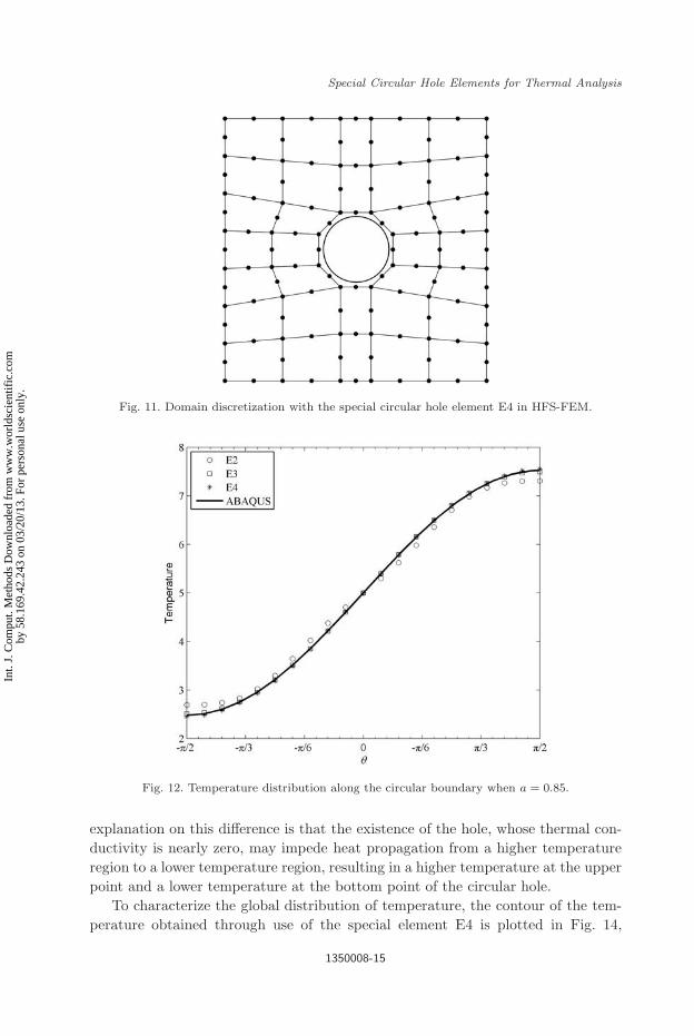
It is also important to investigate the effect of nodal numbers on element per-formance. To this end, the special circular hole elements E3 and E4 with moreelemental edges and 16 nodes are constructed (see Fig. 5), and the correspond-ing mesh divisions with 33 elements are provided in Figs. 10 and 11, respectively.Figures 12 and 13 display the temperature distribution along the circular boundaryand the line X1 = 1.5, from which it can be seen that the special elements E3 andE4 achieve better accuracy than the special element E2 in the case of a/D = 1.0625.The relative errors in temperature at the point (1.5, 1.9) are 2.8%, 0.4%, and 0.4%for E2, E3 and E4, respectively, for comparison. The numerical results also showthat the HFS-FEM is insensitive to mesh distortion. Additionally, it is found fromFig. 13 that the results from both special purpose elements E3 and E4 are in goodagreement with those from ABAQUS (see the dotted line in Fig. 13), although thenumber of elements employed is much smaller than that in ABAQUS (see Figs. 7,10 and 11). It is also found that the temperature at the point (1.5, 1.9) is 7.5540in the presence of a circular hole and 6.3333 without a circular hole. The physical
Fig. 10. Domain discretization with the special circular hole element E3 in HFS-FEM.
1350008-14
Int.
J. C
ompu
t. M
etho
ds D
ownl
oade
d fr
om w
ww
.wor
ldsc
ient
ific
.com
by 5
8.16
9.42
.243
on
03/2
0/13
. For
per
sona
l use
onl
y.
2nd Reading
March 9, 2013 12:17 WSPC/0219-8762 196-IJCM 1350008
Special Circular Hole Elements for Thermal Analysis
Fig. 11. Domain discretization with the special circular hole element E4 in HFS-FEM.
Fig. 12. Temperature distribution along the circular boundary when a = 0.85.
explanation on this difference is that the existence of the hole, whose thermal con-ductivity is nearly zero, may impede heat propagation from a higher temperatureregion to a lower temperature region, resulting in a higher temperature at the upperpoint and a lower temperature at the bottom point of the circular hole.
To characterize the global distribution of temperature, the contour of the tem-perature obtained through use of the special element E4 is plotted in Fig. 14,
1350008-15
Int.
J. C
ompu
t. M
etho
ds D
ownl
oade
d fr
om w
ww
.wor
ldsc
ient
ific
.com
by 5
8.16
9.42
.243
on
03/2
0/13
. For
per
sona
l use
onl
y.

2nd Reading
March 9, 2013 12:17 WSPC/0219-8762 196-IJCM 1350008
Q. H. Qin & H. Wang
Fig. 13. Temperature distribution along the line X1 = 1.5 when a = 0.85.
in which the effect of the circular hole on the temperature distribution is clearlydemonstrated.
5.2. Square plate with double holes
In the second example, we consider the problem of two circular holes embeddedin a square plate, shown in Fig. 15. The circular holes are located on a line andhave central coordinates (0.95, 1.5) and (2.05, 1.5), respectively, and both have theradius R = 0.4.
Only half of the domain is considered in the computation, due to the symmetryof the problem, and 15 elements, consisting of 14 general elements E1 and one specialelement E3 with aspect ratio a/D = 1.375 (see Fig. 16), are used. Figures 17 and 18present the temperature distribution along the boundary of the circular hole andalong the line x1 = 1.5, respectively. It is observed that good agreement is achievedbetween the results from the proposed HFS-FEM and those of ABAQUS, whichused as many as 1094 8-node quadrilateral isoparametric elements. Compared to thecase of a single hole, the maximum temperature on the circular boundary increasesfrom 7.5540 (single hole) to 7.7417 (double holes), and the minimum temperaturedecreases from 2.4460 (single hole) to 2.2583 (double holes), as was expected.
Finally, the global distribution of temperature in the entire square domain underconsideration is plotted in Fig. 19, from which the effect of double holes temperature
1350008-16
Int.
J. C
ompu
t. M
etho
ds D
ownl
oade
d fr
om w
ww
.wor
ldsc
ient
ific
.com
by 5
8.16
9.42
.243
on
03/2
0/13
. For
per
sona
l use
onl
y.

2nd Reading
March 9, 2013 12:17 WSPC/0219-8762 196-IJCM 1350008
Special Circular Hole Elements for Thermal Analysis
Fig. 14. (Color online) Global temperature distribution in the domain with one centered circularhole using E4 and a = 0.85.
Fig. 15. Geometry and boundary conditions of numerical model with two aligned circular holes.
1350008-17
Int.
J. C
ompu
t. M
etho
ds D
ownl
oade
d fr
om w
ww
.wor
ldsc
ient
ific
.com
by 5
8.16
9.42
.243
on
03/2
0/13
. For
per
sona
l use
onl
y.

2nd Reading
March 9, 2013 12:17 WSPC/0219-8762 196-IJCM 1350008
Q. H. Qin & H. Wang
Fig. 16. Mesh division with 14 general elements E1 and one special element E3.
Fig. 17. Temperature distribution along the left circular boundary.
distribution is clear and the effect of simultaneous interaction between holes on thetemperature distribution are observed.
5.3. Square plate with randomly distributed holes
As the final example we demonstrate the use of the presented approach for solvingproblems with multiple randomly distributed circular holes. To this end, consider
1350008-18
Int.
J. C
ompu
t. M
etho
ds D
ownl
oade
d fr
om w
ww
.wor
ldsc
ient
ific
.com
by 5
8.16
9.42
.243
on
03/2
0/13
. For
per
sona
l use
onl
y.

2nd Reading
March 9, 2013 12:17 WSPC/0219-8762 196-IJCM 1350008
Special Circular Hole Elements for Thermal Analysis
Fig. 18. Temperature distribution along the line X1 = 1.5.
Fig. 19. (Color online) Global temperature distribution in the square domain with two alignedcircular holes.
1350008-19
Int.
J. C
ompu
t. M
etho
ds D
ownl
oade
d fr
om w
ww
.wor
ldsc
ient
ific
.com
by 5
8.16
9.42
.243
on
03/2
0/13
. For
per
sona
l use
onl
y.

2nd Reading
March 9, 2013 12:17 WSPC/0219-8762 196-IJCM 1350008
Q. H. Qin & H. Wang
Fig. 20. Geometry and boundary conditions of the numerical model with six randomly distributedcircular holes.
again the same square plate given above, but with six randomly distributed circularholes named C1, C2, C3, C4, C5 and C6 (see Fig. 20). The central coordinates ofC1, C2, C3, C4, C5 and C6 are (0.5, 0.5), (2.2, 0.6), (1.0, 1.6), (2.4, 1.6), (0.6, 2.6),and (2.0, 2.4), respectively. The radii of C1, C2, and C3 are assumed to be 0.4, andthat of C4, C5, and C6 to be 0.3.
Assume that all circular boundaries are insulated in the following calculation,and 52 elements, including 46 general elements E1 and six special purpose elementsE3 are used to model the solution domain (see Fig. 21). The curve in Fig. 22 showsthe temperature distribution along the circular boundaries of C1 and C6, and good
Fig. 21. Mesh division with 46 general elements E1 and six special elements E3.
1350008-20
Int.
J. C
ompu
t. M
etho
ds D
ownl
oade
d fr
om w
ww
.wor
ldsc
ient
ific
.com
by 5
8.16
9.42
.243
on
03/2
0/13
. For
per
sona
l use
onl
y.

2nd Reading
March 9, 2013 12:17 WSPC/0219-8762 196-IJCM 1350008
Special Circular Hole Elements for Thermal Analysis
Fig. 22. Temperature distribution along the circular boundary C1 and C6.
Fig. 23. (Color online) Global temperature distribution in the square domain with six randomlydistributed circular holes.
1350008-21
Int.
J. C
ompu
t. M
etho
ds D
ownl
oade
d fr
om w
ww
.wor
ldsc
ient
ific
.com
by 5
8.16
9.42
.243
on
03/2
0/13
. For
per
sona
l use
onl
y.

2nd Reading
March 9, 2013 12:17 WSPC/0219-8762 196-IJCM 1350008
Q. H. Qin & H. Wang
agreement is observed again between the results from the presented approach andthose from ABAQUS, which used as many as 5549 elements. Additionally, the globalcontour of the temperature field in the domain is given in Fig. 23, from which wecan see that the temperature distribution is more complex than in the cases of singleand double holes, due to the effect of the holes and their interactions.
The example demonstrates that by using the special purpose elements we canachieve a level of accuracy similar to that of ABAQUS, but using a much smallernumber of elements. Obviously this feature can significantly save computing time.
6. Conclusions
This paper presents three types of special purpose elements within the frameworkof a fundamental-solution-based hybrid FEM for analyzing the thermal behavior ofcellular solids with multiple randomly distributed circular holes. The special purposeelements are constructed by using the special fundamental solution satisfying thehole boundary condition. In the approach, all the integrations are performed alongthe element boundary only, and it is not necessary to refine meshes for the regionnear the circular hole. Three numerical examples are considered, including problemswith a single hole, double holes, and randomly distributed multiple holes, to verifythe proposed computational model. Numerical results from the presented modelshow good agreement with those from ABAQUS, but with a much smaller numberof elements. Therefore the high accuracy and efficiency of the presented approachwith special circular hole elements have been demonstrated. It is a promising methodfor efficiently solving large-scale problems with multiple circular holes. Moreover, itcan be seen from the solution procedure described above that the present approachcan conveniently be extended to solving cellular solids weakened by other shapedholes, if the corresponding kernel functions such as special fundamental solutionsare available.
Acknowledgment
The research in this paper is partially supported by the Natural Science Foundationof China under the grant no. 11102059.
References
Ang, W. T. [2007] A Beginner’s Course in Boundary Element Methods (UniversalPublishers, Boca Raton, FL).
Chen, J. T. and Lee, Y. T. [2009] “Torsional rigidity of a circular bar with multiple circularinclusions using the null-field integral approach,” Comput. Mech. 44, 221–232.
Chen, J. T. and Wu, C. S. [2006] “Alternative derivations for the poisson integral formula,”Int. J. Math. Educ. Sci. Technol. 37, 165–185.
Chen, J. T., Lee, Y. T. and Lee, J. W. [2010] “Torsional rigidity of an elliptic bar withmultiple elliptic inclusions using a null-field integral approach,” Comput. Mech. 46,511–519.
1350008-22
Int.
J. C
ompu
t. M
etho
ds D
ownl
oade
d fr
om w
ww
.wor
ldsc
ient
ific
.com
by 5
8.16
9.42
.243
on
03/2
0/13
. For
per
sona
l use
onl
y.

2nd Reading
March 9, 2013 12:17 WSPC/0219-8762 196-IJCM 1350008
Special Circular Hole Elements for Thermal Analysis
Chen, J. T., Wu, C. S., Lee, Y. T. and Chen, K. H. [2007] “On the equivalence of the Trefftzmethod and method of fundamental solutions for Laplace and biharmonic equations,”Comput. Math. Appl. 53, 851–879.
Dejoie, A., Mogilevskaya, S. G. and Crouch, S. L. [2006] “A boundary integral method formultiple circular holes in an elastic half-plane,” Eng. Anal. Bound. Elem. 30, 450–464.
Dhanasekar, M., Han, J. J. and Qin, Q. H. [2006] “A hybrid-Trefftz element containing anelliptic hole,” Finite Elem. Anal. Des. 42, 1314–1323.
Duan, Z. P., Kienzler, R. and Herrmann, G. [1986] “An integral equation method and itsapplication to defect mechanics,” J. Mech. Phys. Solids 34, 539–561.
Helsing, J. and Jonsson, A. [2001] “Complex variable boundary integral equations forperforated infinite planes,” Eng. Anal. Bound. Elem. 25, 191–202.
Kupradze, V. D. and Aleksidze, M. A. [1964] “The method of functional equations forthe approximate solution of certain boundary value problems,” USSR Comput. Math.Math. Phys. 4, 82–126.
Lee, W. M., Chen, J. T. and Lee, Y. T. [2007] “Free vibration analysis of circular plateswith multiple circular holes using indirect BIEMs,” J. Sound Vib. 304, 811–830.
Martin, H. C. and Carey, G. F. [1973] Introduction to Finite Element Analysis: Theoryand Applications (McGraw-Hill, New York).
Mogilevskaya, S. G. and Crouch, S. L. [2001] “A Galerkin boundary integral method formultiple circular elastic inclusions,” Int. J. Numer. Meth. Eng. 52, 1069–1106.
Mogilevskaya, S. G. and Crouch, S. L. [2002] “A Galerkin boundary integral method formultiple circular elastic inclusions with homogeneously imperfect interfaces,” Int. J.Solid Struct. 39, 4723–4726.
Piltner, R. [2008] “Some remarks on hybrid-Trefftz finite elements with elliptic holes,”Finite Elem. Anal. Des. 44, 767–772.
Qin, Q. H. [1993] “Nonlinear analysis of Reissner plates on an elastic foundation by theBEM,” Int. J. Solid Struct. 30, 3101–3111.
Qin, Q. H. [1995] “Hybrid Trefftz finite element method for Reissner plates on an elasticfoundation,” Comput. Meth. Appl. Mech. Eng. 122, 379–392.
Qin, Q.-H. and Diao, S. [1996] “Nonlinear analysis of thick plates on an elastic foundationby HT FE with p-extension capabilities,” Int. J. Solid Struct. 33, 4583–4604.
Qin, Q. H. [2000] The Trefftz Finite and Boundary Element Method (WIT Press,Southampton).
Qin, Q. H. [2003] “Solving anti-plane problems of piezoelectric materials by the Trefftzfinite element approach,” Comput. Mech. 31, 461–468.
Qin, Q. H. and Wang, H. [2009] Matlab and C Programming for Trefftz Finite ElementMethods (CRC Press, New York).
Ting, K., Chen, K. T. and Yang, W. S. [1999] “Applied alternating method to analyze thestress concentration around interacting multiple circular holes in an infinite domain,”Int. J. Solid Struct. 36, 533–556.
Wang, H. and Qin, Q. H. [2007] “Some problems with the method of fundamental solutionusing radial basis functions,” Acta Mech. Solida Sin. 20, 21–29.
Wang, H. and Qin, Q. H. [2008] “Meshless approach for thermo-mechanical analysis offunctionally graded materials,” Eng. Anal. Bound. Elem. 32, 704–712.
Wang, H. and Qin, Q. H. [2009] “Hybrid FEM with fundamental solutions as trial functionsfor heat conduction simulation,” Acta Mech. Solida Sin. 22, 487–498.
Wang, H. and Qin, Q. H. [2010a] “FE approach with Green’s function as internal trialfunction for simulating bioheat transfer in the human eye,” Arch. Mech. 62, 493–510.
Wang, H. and Qin, Q. H. [2010b] “Fundamental-solution-based finite element model forplane orthotropic elastic bodies,” Eur. J. Mech. Solid 29, 801–809.
1350008-23
Int.
J. C
ompu
t. M
etho
ds D
ownl
oade
d fr
om w
ww
.wor
ldsc
ient
ific
.com
by 5
8.16
9.42
.243
on
03/2
0/13
. For
per
sona
l use
onl
y.

2nd Reading
March 9, 2013 12:17 WSPC/0219-8762 196-IJCM 1350008
Q. H. Qin & H. Wang
Wang, H. and Qin, Q. H. [2011a] “Special fiber elements for thermal analysis of fiber-reinforced composites,” Eng. Comput. 28, 1079–1097.
Wang, H. and Qin, Q. H. [2011b] “Fundamental-solution-based hybrid FEM for planeelasticity with special elements,” Comput. Mech. 48, 515–528.
Wang, H. and Qin, Q. H. [2012] “Boundary integral based graded element for elasticanalysis of 2D functionally graded plates,” Eur. J. Mech. Solid 33, 12–23.
Wang, H., Qin, Q. H. and Arounsavat, D. [2007] “Application of hybrid Trefftz finiteelement method to non-linear problems of minimal surface,” Int. J. Numer. Meth.Eng. 69, 1262–1277.
Wang, J., Crouch, S. L. and Mogilevskaya, S. G. [2003] “A complex boundary integralmethod for multiple circular holes in an infinite plane,” Eng. Anal. Bound. Elem. 27,789–802.
Young, D. L., Jane, S. J., Fan, C. M., Murugesan, K. et al. [2006] “The method of funda-mental solutions for 2D and 3D Stokes problems,” J. Comput. Phys. 211, 1–8.
1350008-24
Int.
J. C
ompu
t. M
etho
ds D
ownl
oade
d fr
om w
ww
.wor
ldsc
ient
ific
.com
by 5
8.16
9.42
.243
on
03/2
0/13
. For
per
sona
l use
onl
y.


![Topology optimization for concurrent design of structures ...users.cecs.anu.edu.au/~Qinghua.Qin/publications/... · macro structural and microstructural designs [4,5]. Having regard](https://img.dokumen.tips/doc/110x75/5f2f3a4af2a02e7fff231c08/topology-optimization-for-concurrent-design-of-structures-userscecsanueduau.jpg)


![PARTE DIARIO - chfutaleufu.com.ar · PARTE DIARIO Estaciones Meteorologicas Lluvia Diaria [mm] Lluvia Mensual [mm] ... ND 5.1 ND ND ND ND 12.8 ND ND ND (Lago Futalaufquen) (Pto Rios)](https://img.dokumen.tips/doc/110x75/5c0da76209d3f23c2a8bb4cf/parte-diario-parte-diario-estaciones-meteorologicas-lluvia-diaria-mm-lluvia.jpg)