Embed Size (px)
Citation preview

NCWABENI OFF-CHANNEL STORAGE DAM FEASIBILITY STUDY:
MODULE 1: TECHNICAL STUDY
SUPPORTING REPORT 2:
GEOTECHNICAL AND MATERIALS INVESTIGATION
FINAL
PREPARED BY: PREPARED FOR:
BKS (Pty) Ltd
PO Box 3173
PRETORIA
0001
Department of Water Affairs:
Directorate Options Analysis
Private Bag X313
PRETORIA
0001
CONTACT PERSON CONTACT PERSON
Mr JH Schroder Mr JA Bester
Tel: 012 421 3533 Tel: 012 336 8071

Report Details Page
Project name: Ncwabeni Off-Channel Storage Dam Feasibility Study: Module 1: Technical Study
Report Title: Supporting Report 2: Geotechnical and Materials Investigation
Author: Prof. A van Schalkwyk, R S Naidoo
PSP project reference no.: J01494
Status of report: Final
First issue:
Final issue:
January 2012
April 2012
CONSULTANT: BKS (Pty) Ltd
Approved for Consultants by:
Prof. A van Schalkwyk Task Leader
JLJ van der Westhuizen Study Leader
DEPARTMENT OF WATER AFFAIRS (DWA)
Approved for Directorate: Options Analysis by:
JA Bester Chief Engineer: Options Analysis (East)
P Pyke
Acting Director: Options Analysis

Ncwabeni Off-Channel Storage Dam Feasibility Study: Module 1: Technical Study Final
P:\J01494 - Ncwabeni feasibility study\Reports\Geotech report\Geotechnical and materials investigation report_final.docx
i
EXECUTIVE SUMMARY TERMS OF REFERENCE AND SCOPE OF WORK A pre-feasibility study by DWA for the Ncwabeni Off-Channel Storage Project near Port Shepstone that was completed in February 2005, identified two alternative dam sites namely the D2 site on the Ncwabeni River and the D3 site on the Gugamela River. Capital costs and the UVRs associated with the two alternatives were found to be almost identical but Site D2 was preferred from environmental and social perspectives. Selection of the preferred option would therefore largely depend on costs associated with geotechnical conditions at the dam sites (including the possibility of a fatal flaw at D2), availability of construction materials and slope stability.
During 20011, BKS (Pty) Ltd undertook feasibility stage geotechnical and materials investigation to assist with the site selection and other studies which will allow accurate costing and commencement of construction works.
The purpose and scope of the geotechnical investigations were to:
• Review the available geotechnical information.
• Describe the general geology of the area and prepare a geological map.
• Investigate any potential flaws for construction of a dam at Site D2.
• Investigate sources for dam construction materials.
• Undertake geotechnical investigations for the dam foundations, spillway structure, diversion weir in the Umzimkulu River, pump station and the rising main.
• Assess the stability of slopes around the reservoir rim.
This report describes the site conditions, based on a desktop study and field investigations conducted from 21 February 2011 to 3 March 2011 and from 25 July 2011 to 7 October 2011. Laboratory testing was completed in December 2011.
GEOLOGY
The project area including the dam centre line, the spillway line, weir sites, pump station site, quarry site and most of the borrow areas are underlain by granitic bedrock of the Oribi Gorge Suite. This rock is weathered to various degrees and depths across the area, with slightly weathered to unweathered rock on surface or at shallow depth near the rivers and deeper weathering in the higher lying areas.
The bedrock is generally covered by layers of colluvial clayey silty sand in the higher lying areas, while there are well-developed layers of alluvial silt, sand and gravel closer to the rivers.
FATAL FLAW
During the initial stages of the investigation, attention was given to the possible occurrence of a fatal flaw at Site D2. However nothing that would rule out the construction of a dam or would result in excessive cost was identified.
CONSTRUCTION MATERIALS
It was not possible to locate sufficient quantities of impervious core material for construction of a zoned embankment dam within the dam basins or elsewhere in the area. The only alternative type of embankment is a concrete-faced rockfill dam. Such a dam comprising of “soft” and “hard” rockfill zones can be constructed from completely and highly weathered granite (soft

Ncwabeni Off-Channel Storage Dam Feasibility Study: Module 1: Technical Study Final
P:\J01494 - Ncwabeni feasibility study\Reports\Geotech report\Geotechnical and materials investigation report_final.docx
ii
rockfill) and moderately weathered to unweathered granite (hard rockfill) that can be obtained from a proposed quarry in the D2 dam basin. Good quality concrete aggregate for construction of the concrete face can be obtained from rock in the bottom part of the quarry.
DAM FOUNDATIONS
A wide fault zone and generally deep weathering on the left flank of site D2 will require very deep excavation for a concrete gravity (RCC) dam indicating that its cost will far exceed those for embankment or composite dams.
A composite dam with a concrete overspill section in the river and along the right flank might be considered, but the left embankment will have to be supported by a long flank wall, the founding levels of which have not been investigated, but are expected to be about 10 m deep.
Investigations along the dam centre line show that founding conditions for a rock-fill dam are favourable with excavation depths not exceeding about 5 m and grouting to depths of between 20 m and 40 m. However, the plinth for an upstream faced rockfill dam will be located a considerable distance upstream of the dam reference line, and for the design purposed, additional geotechnical investigations will have to be conducted.
SPILLWAY AND RISING MAIN
The proposed spillway control structure on the upper left flank may have to be relocated because of deep weathering in that area. The proposed return channel will need to be concrete-lined and will be founded on highly weathered (soft rock) granite with local zones of completely weathered granite (very soft rock).
It is recommended that additional investigations be conducted during the design stage to select the most favourable position for the spillway control structure and to determine the required founding levels.
WEIR FOUNDATIONS
The lower weir site has good founding conditions ion the left flank and in the river section. However, the flat-lying right flank is underlain by thick alluvium.
PUMP STATION
Alluvium of variable thickness is underlain by good quality founding rock. Founding levels will depend on the position selected for the pump station.
RESERVOIR SLOPE STABILITY
In the unlikely event of a slope failure along the rim of the reservoir, the volume of mobilised material will be very small (less than 0.3% of the reservoir volume) and the effect on the dam level will be minimal.

Ncwabeni Off-Channel Storage Dam Feasibility Study: Module 1: Technical Study Final
P:\J01494 - Ncwabeni feasibility study\Reports\Geotech report\Geotechnical and materials investigation report_final.docx
i
Table of Contents
1 INTRODUCTION .................................................................................................... 1
1.1 Background to the project ......................................................................... 1
1.2 Scope and organisation of the study ......................................................... 2
1.3 Purpose of the Report ............................................................................... 3
2 PREVIOUS INVESTIGATIONS .............................................................................. 4
2.1 Seismic Hazard Analysis .......................................................................... 4
2.2 Foundation investigation ........................................................................... 4
2.3 Materials investigations ............................................................................ 4
3 INVESTIGATION METHODS AND STANDARDS .................................................. 5
3.1 Site Conditions ......................................................................................... 5
3.2 Geological Mapping .................................................................................. 5
3.3 Seismic Refraction Survey ........................................................................ 5
3.4 Test Pits ................................................................................................... 5
3.5 Rotary Core Drilling .................................................................................. 6
3.6 Laboratory Testing .................................................................................... 7
4 GEOLOGY ............................................................................................................. 8
4.1 General Geology ...................................................................................... 8
4.2 Oribi Gorge Suite ...................................................................................... 8
4.3 Dwyka Tillite ............................................................................................. 8
4.4 Alluvial Deposits ....................................................................................... 8
4.5 Colluvial Materials .................................................................................... 8
5 IDENTIFICATION OF POTENTIAL FATAL FLAWS ............................................. 10
6 CONSTRUCTION MATERIALS INVESTIGATION ............................................... 11
6.1 Earth fill Materials ................................................................................... 12
6.1.1 Test Pits ................................................................................................. 12
6.1.2 Laboratory Test Results .......................................................................... 15
6.1.3 Available Quantities of Earth Fill Material ................................................ 18
6.2 Rock Materials ........................................................................................ 20
6.2.1 Cored Boreholes ..................................................................................... 20
6.2.2 Laboratory Testing .................................................................................. 21
6.2.3 Available Volumes of Rockfill Material .................................................... 21
7 GEOTECHNICAL INVESTIGATIONS .................................................................. 23
7.1 Dam Centre Line .................................................................................... 23
7.1.1 Seismic Refraction Survey ...................................................................... 23
7.1.2 Test Pits ................................................................................................. 23

Ncwabeni Off-Channel Storage Dam Feasibility Study: Module 1: Technical Study Final
P:\J01494 - Ncwabeni feasibility study\Reports\Geotech report\Geotechnical and materials investigation report_final.docx
ii
7.1.3 Cored Boreholes ..................................................................................... 24
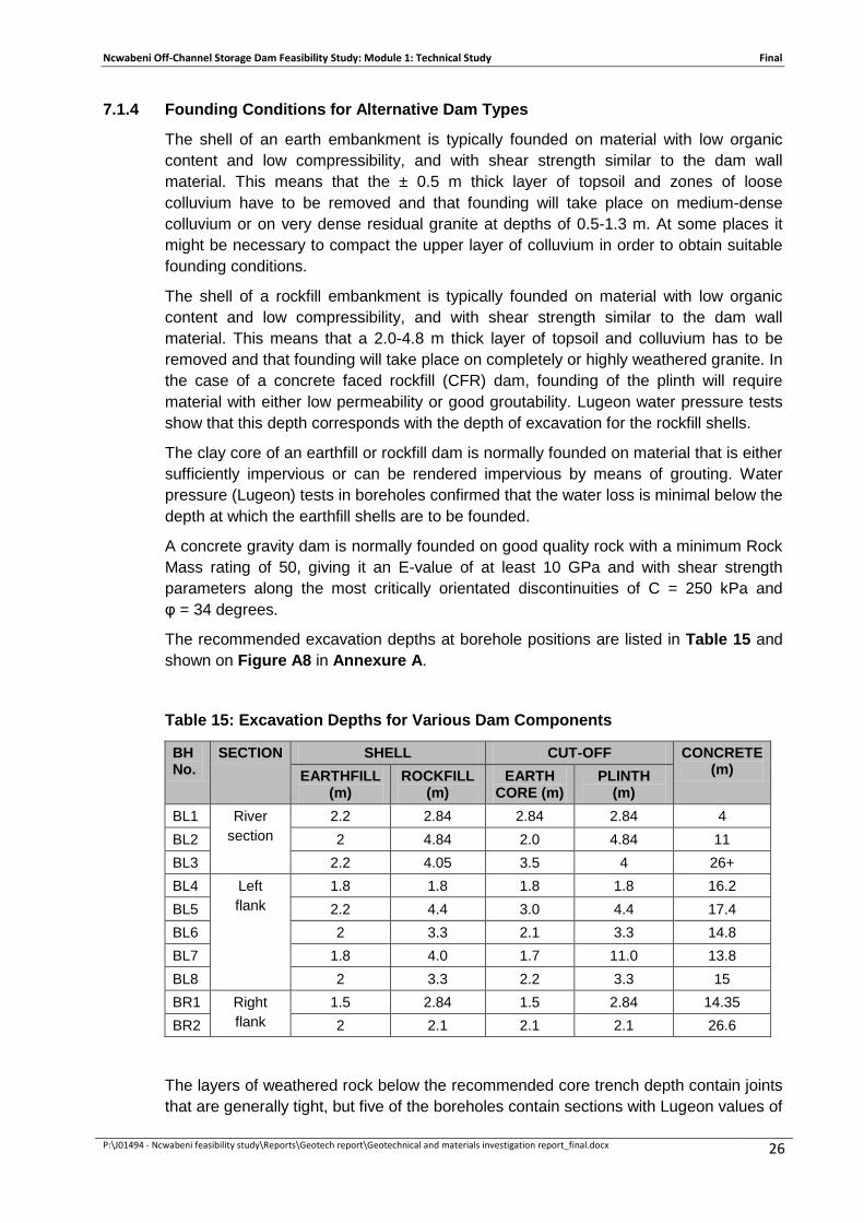
7.1.4 Founding Conditions for Alternative Dam Types ..................................... 26
7.2 Spillway and Rising Main ........................................................................ 27
7.2.1 Seismic Refraction Survey ...................................................................... 27
7.2.2 Test Pits ................................................................................................. 27
7.2.3 Cored Boreholes ..................................................................................... 28
7.2.4 Founding Conditions ............................................................................... 29
7.3 Alternative Weir Sites ............................................................................. 30
7.3.1 Cored Boreholes ..................................................................................... 30
7.3.2 Founding Conditions ............................................................................... 30
7.4 Pump Station .......................................................................................... 31
7.4.1 Cored Boreholes ..................................................................................... 31
7.4.2 Founding Conditions ............................................................................... 31
8 RESERVOIR SLOPE STABILITY ......................................................................... 32
9 CONCLUSIONS ................................................................................................... 33
9.1 Geology .................................................................................................. 33
9.2 Potential Fatal Flaw ................................................................................ 33
9.3 Construction Materials ............................................................................ 33
9.4 Founding Conditions ............................................................................... 33
9.4.1 Dam ........................................................................................................ 33
9.4.2 Spillway and Rising Main ........................................................................ 34
9.4.3 Weir ........................................................................................................ 34
9.4.4 Pump Station .......................................................................................... 34
9.5 Reservoir Slope Stability ......................................................................... 34
10 REFERENCES ..................................................................................................... 35

Ncwabeni Off-Channel Storage Dam Feasibility Study: Module 1: Technical Study Final
P:\J01494 - Ncwabeni feasibility study\Reports\Geotech report\Geotechnical and materials investigation report_final.docx
iii
List of Annexures Annexure A Figures
A1 – Locality Map and Catchment Areas A2 – Geological Map of Investigation Areas and Immediate Surrounds A3 – Geotechnical Test Pit Positions at Site D2 A4 – Geotechnical Test Pit Positions at Site D3 A5 – Contour plan showing Borehole Positions and Seismic Results A6 – Proposed Quarry Areas and River Diversion A7.1 – Geotechnical Sections through Quarry Area A7.2 – Geotechnical Sections through Quarry Area A8.1 – Longitudinal Section along Dam Reference Line A8.1 – Longitudinal Section along Dam Reference Line A9 – Longitudinal Sections along Spillway Line and Approach Area A10 – Borehole Profiles at Alternative Weir Sites A11 – Borehole profiles at Pump Station Sites A12 – Contour Map of Dam Basin showing Potential Instability
Annexure B Soil Profiles
Annexure C Laboratory Results
Annexure D Borehole Logs
Annexure E Core Photographs
Annexure F Seismic Refraction Report
List of Tables
Table 1: Summary of Test Pit Excavations ....................................................................................... 6
Table 2: Summary of Cored Boreholes ............................................................................................. 7
Table 3: Approximate Volumes of Construction Material Required ............................................ 11
Table 4: DWA Specification for Embankment Materials ............................................................... 11
Table 5: Summary of Soil Profiles in Potential Borrow Areas ...................................................... 12
Table 6: Summary of Laboratory Test Results .............................................................................. 15
Table 7: Summary of Proctor Compaction Results ....................................................................... 17
Table 8: Summary of Permeability Test Results............................................................................ 18
Table 9: Summary of CU Triaxial Test Results .............................................................................. 18
Table 10: Summary of Borehole Logs in the proposed quarry area in the D2 Basin ............... 20
Table 11: Summary of laboratory tests on crushed rock cores ................................................... 21
Table 12: Summary of Soil Profiles along the Dam Centreline ................................................... 24

Ncwabeni Off-Channel Storage Dam Feasibility Study: Module 1: Technical Study Final
P:\J01494 - Ncwabeni feasibility study\Reports\Geotech report\Geotechnical and materials investigation report_final.docx
iv
Table 13: Summary of Borehole Logs along the Dam Centre line ............................................. 25
Table 14: Summary of water test results ........................................................................................ 25
Table 15: Excavation Depths for Various Dam Components ............................................... 26
Table 16: Summary of Soil Profiles along the Spillway ................................................................ 28
Table 17: Summary of Borehole Logs Along the Spillway line .................................................... 28
Table 18: Founding Depths for Spillway ......................................................................................... 29
Table 19: Summary of Borehole Logs at the Weir Sites .............................................................. 30
Table 20: Summary of Borehole Logs at the Pump Station Sites ............................................... 31
List of Acronyms ACR Asphalt core rockfill
BCR Bentonite core rockfill
CCR Clay core rockfill
CFT Concrete faced rockfill,
DWA Department of Water Affairs
EIA Environmental impact assessment
FSL Full storage level
GPS Global positioning system
LL Liquid Limit
LS Linear Shrinkage
Masl mean annual sea level
MDD Maximum Dry Density
OCS Off-channel Storage
OMC Optimum Moisture Content
PGA Probable Maximum Acceleration
PI Plasticity Index
PSP Professional service provider
RCC Roller compacted concrete
RQD Rock quality designation
RWSS Regional Water Supply Scheme
TPH Test Pit (Horseshoe area)
URV Unit reference value
USCS Unified Soil Classification System
Ncwabeni Off-Channel Storage Dam Feasibility Study: Module 1: Technical Study Final
P:\J01494 - Ncwabeni feasibility study\Reports\Geotech report\Geotechnical and materials investigation report_final.docx 1
1 INTRODUCTION
1.1 BACKGROUND TO THE PROJECT
The Umzimkhulu Regional Water Supply Scheme (RWSS), which forms part of the KwaZulu Natal’s Lower South Coast System, supplies water to the coastal region from Hiberdeen to Margate, including Port Shepstone. The water is presently sourced from non-regulated river flows in the Umzimkhulu River. Abstraction is at the St. Helen’s Rock works near Port Shepstone where water is treated and from where it is distributed to various user nodes.
The Southern KwaZulu-Natal Water Resources Pre-feasibility Study Phase 1 (DWA, 2002), concluded that during dry periods, the river flow is sufficient to meet the water requirements, even without provision for the release of the ecological Reserve. The study recommended that, in order to provide for the water requirements for all user sectors, including the Reserve, the construction of an off-channel storage (OCS) dam in one of the tributaries to the Mzimkhulu River, should be considered. The reservoir can be filled from its incremental catchment, supplemented by pumping from the Mzimkhulu River during times of high river flows. During times of low flows water can be released back into the Mzimkhulu River for abstraction downstream at the existing St. Helen’s Rock abstraction works.
The Southern KwaZulu-Natal Water Resources Pre-feasibility Study Phase 2 (DWA, 2005), investigated numerous options with regard to the position of the potential OCS dams. Four competitive sites which are located about 20km north-west of Port Shepstone were selected as the most feasible OCS dam sites. Two of the sites (D2 and D2A) are located on the Ncwabeni River while the other two (D3 and D3A) are on the Gugamela River. Conceptual designs for dams at these sites were undertaken as part of the afore-mentioned study.
Following on the above, the Reconnaissance Phase of the Mzimkhulu River Off-Channel Storage Pre-feasibility Study (DWA, 2007), re-assessed all four OCS dam options on the basis of more detailed hydrological modelling and updated information regarding water requirements, topographical surveys, geotechnical and flood hydrology data. It was established that the D3 site on the Gugamela River and the D2A site on the Ncwabeni River were distinctly less favourable than the other two sites and were therefore not investigated further. The study concluded that the geological conditions for the sites on the Ncwabeni River are superior to those on the Gugamela River and that the construction of a Roller Compacted Concrete (RCC) dam at the D2 site on the Ncwabeni River appeared the most feasible option.
Subsequently the Ncwabeni Off-channel Storage Dam Feasibility Study: Module 1: Technical Study (this study) was initiated to conduct a comprehensive engineering investigation at the feasibility level for the proposed Ncwabeni Off-Channel Storage Scheme. The possible dam at site D2 on the Ncwabeni River was to be considered first and if a fatal flaw or substantial increase in cost is identified, site D3A on the Gugamela River should then be considered.

Ncwabeni Off-Channel Storage Dam Feasibility Study: Module 1: Technical Study Final
P:\J01494 - Ncwabeni feasibility study\Reports\Geotech report\Geotechnical and materials investigation report_final.docx 2
1.2 SCOPE AND ORGANISATION OF THE STUDY
The key objectives of the study are to:
• Recommend the optimum scheme configuration; • Undertake feasibility level dam foundation, reservoir slope stability and
construction material investigations including quarries; • Undertake the necessary supporting investigations and studies to support the
feasibility study required for the implementation of the scheme; • Do sufficient design of infrastructure to obtain cost estimates; • Collaboration with the appointed PSP that will be responsible for the EIA
process; • Optimise the engineering and economic parameters and determine cost
estimates for the following components of the scheme; the dam, pipeline, pump station, abstraction works, diversion weir and access roads; and
• Provide institutional arrangements for the smooth implementation of the scheme.
The sequence of activities in order from beginning to end followed in this feasibility study included the following:
• Water resource including yield analysis for both the Gugamela and Ncwabeni Dam sites;
• Foundation and construction materials investigation; • Cost comparison of dam types for both Gugamela and Ncwabeni Dams for the
yield associated with the most likely water demand; • Selection of site and dam type; • Cost comparison of scheme for incremental yield to the highest water demand; • Hydraulic model study of Mzimkhulu River to identify three possible sites for
abstraction works; • Selection of the best layout for abstraction works and diversion weir. • Selection and cost comparison of abstraction work, diversion weir, pump
station, pipeline and access road layouts for the three identified sites; • Hydraulic model study of selected abstraction work, diversion weir and pump
station for optimisation; • Optimization and cost comparison analysis of selected scheme; • Conceptual design of selected scheme; and • Determination of URV of water supplied.
The activities specific to the geological and materials task included
• Review the available geotechnical information. • Describe the general geology of the area and prepare a geological map.

Ncwabeni Off-Channel Storage Dam Feasibility Study: Module 1: Technical Study Final
P:\J01494 - Ncwabeni feasibility study\Reports\Geotech report\Geotechnical and materials investigation report_final.docx 3
• Investigate any potential flaws for construction of a dam at Site D2. • Investigate sources for dam construction materials. • Undertake geotechnical investigations for the dam foundations, spillway
structure, diversion weir in the Mzimkulu River, pump station and the rising main.
• Assess the stability of slopes around the reservoir rim.
1.3 PURPOSE OF THE REPORT
The purpose of the report is to present the site conditions, methodology and results of the geological and materials investigation task of the study. The information is based on a desktop study and field investigations conducted (21 February 2011 to 3 March 2011 and from 25 July 2011 to 7 October 2011). Laboratory testing was completed in December 2011.
This information is required input into the engineering, financial and institutional investigations tasks, and this report is thus a supporting report to the main study report.

Ncwabeni Off-Channel Storage Dam Feasibility Study: Module 1: Technical Study Final
P:\J01494 - Ncwabeni feasibility study\Reports\Geotech report\Geotechnical and materials investigation report_final.docx 4
2 PREVIOUS INVESTIGATIONS
2.1 SEISMIC HAZARD ANALYSIS
The Council for Geoscience (2005) reported on a Probabilistic Seismic Hazard Analysis for the proposed site and considered the effect of all the historically recorded earthquakes located within a radius of 320 km from the site to determine
• the mean return periods for the Probable Maximum Acceleration (PGA);
• the annual probability of being exceeded for a specified value of the PGA, and
• uniform ground acceleration spectra.
The service, abnormal and extreme curves show a spectral acceleration peak of approximately 0.02g (at 3Hz), 0.05g (at 5Hz) and 0.15g (at 20Hz).
2.2 FOUNDATION INVESTIGATION
In May 2007, the Council for Geoscience (2007) reported on an engineering geological pre-feasibility study of Site D2 on the Ncwabeni River and Site D3A on the Gugamela River.
The investigations comprised a desktop study of available information, exploratory drilling, discontinuity measurements and limited laboratory testing. At site D2, which is being considered, two rotary-cored boreholes were drilled on the right flank (between the road and the river) and three holes were drilled on the left flank between the river and elevation 139 masl (the present proposed full supply level (FSL) is about 162 masl).
Core recovery and RQD values in the very coarse-grained, moderately weathered granite were generally low due to poor drilling methods, and this raised questions about the predicted excavation depths for a concrete structure of 7-8 m on the lower left flank and up to 25 m on the upper left flank. A review of the log of BH 1004 on the lower left flank showed that founding quality rock was encountered at a depth of 18.4 m, which is much deeper than the depth of 7-8 m that the Council for Geoscience’s report predicted. It was recommended that the possible effects of a major fault and several other faults on the left flank be investigated.
The right flank was considered too steep for an embankment dam. For a clay core on the left flank, excavation depths of 3-6 m were predicted.
2.3 MATERIALS INVESTIGATIONS
In June 2007, the DWA Materials Laboratory reported on a materials investigation within the basin areas of Sites D2 and D3A (DWA, 2007). It was predicted that at Site D2, about 50 000 m3 of semi-pervious material and 55 000 m3 of impervious material could be obtained. At Site D3A, the predicted volume of semi-pervious material is about 6 000 m3 and about 385 000m3 of impervious material.

Ncwabeni Off-Channel Storage Dam Feasibility Study: Module 1: Technical Study Final
P:\J01494 - Ncwabeni feasibility study\Reports\Geotech report\Geotechnical and materials investigation report_final.docx 5
3 INVESTIGATION METHODS AND STANDARDS
3.1 SITE CONDITIONS
The study area is densely vegetated, mostly by indigenous trees. Given that access was almost impossible due to the dense vegetation, the bush was cleared using a 20-ton tracked excavator along the centreline and spillway line to facilitate the geophysical survey and the setting out and excavation of test pits and boreholes.
3.2 GEOLOGICAL MAPPING
Access to the area is very restricted by the dense vegetation, while thick soil cover masks the bedrock and geological structures everywhere except along stream and river courses. Geological mapping of the ground surface was therefore only possible along the road, the river and the access tracks for the drilling and test pitting, while subsurface information was available from the geophysical survey, the test pits and boreholes.
The geological map on a scale of approximately 1:64 000 (Figure 2 in the Council for Geoscience pre-feasibility report) was used as a basis, and was updated with the additional information from the present investigations. This map is shown in Figure A2.
3.3 SEISMIC REFRACTION SURVEY
Seismic refraction surveys were undertaken to determine the depth to sound bedrock along the dam centre line, the spillway line and a proposed quarry site, and to identify local zones of deeper weathering characteristic of fault or shear zones. The results of a seismic survey are used to select the most appropriate positions for exploratory boreholes and to assist with the interpretation of geotechnical conditions between boreholes.
Seismic refraction surveys along the left flank of the dam centre line (400 m), the spillway line (200 m) and at a proposed quarry site (196 m) were conducted by E&EGS cc in March 2011. The report is attached as Annexure F.
The very steep slopes of the right flank and the lower part of the spillway line made it impossible to survey these areas. For the same reason, only one seismic traverse could be done along a contour at the proposed quarry site.
3.4 TEST PITS
Test pits were excavated to investigate the subsurface conditions to a depth of about 4 m. A Komatsu PC220 20-ton excavator with a 1.14 m wide bucket was used (instead of a TLB) to speed up the work and to penetrate the layer of hardpan ferricrete. The refusal depth of a 20-ton excavator can usually be taken to represent the founding depth for the core trench of an embankment dam.
Table 1 shows that 69 test pits were excavated during the site investigations. Eight test pits were excavated along the proposed dam centreline, four along the spillway line and four in the spillway approach area. Test pits were also excavated to identify suitable embankment materials for the construction of the dam: 14 in the area referred to as the horseshoe, nine in the D2 basin and 30 pits in the D3 basin.

Ncwabeni Off-Channel Storage Dam Feasibility Study: Module 1: Technical Study Final
P:\J01494 - Ncwabeni feasibility study\Reports\Geotech report\Geotechnical and materials investigation report_final.docx 6
Table 1: Summary of Test Pit Excavations
Project Area Number of Test Pits Test Pit IDs
Dam Centreline 8 TP01 – TP08 Spillway 4 TP09 – TP12 Spillway Approach Area 4 TP13 – TP16 Horseshoe 14 TP17 – TP24 and TPH01-TPH06 D2 Basin 9 TP25 – TP33
D3 Basin 30 TP34 – TP54, TP56 and TP46a - TP52a, TP54a
The test pits were excavated to a maximum depth of 4 m or to partial refusal (characterised by slow progress), whichever occurred first. Test pits were profiled by an engineering geologist according to the current standards and practice in South Africa (Brink and Bruin, 2002). Representative samples were taken for laboratory testing.
Each test pit was positioned using a hand-held GPS and were subsequently surveyed to an accuracy of 200 mm horizontally and vertically. The plans shown in Figures A3 and A4 in Annexure A indicate the positions of the test pits.
3.5 ROTARY CORE DRILLING
Rotary core drilling was undertaken to obtain relatively undisturbed samples of soil and rock to depths of 20-40 m below ground surface and to conduct packer permeability tests to these depths along the dam centre line.
Borehole cores were profiled by an engineering geologist according to the current standards and practice in South Africa (Brink and Bruin 2002).
Water pressure testing was carried out within the boreholes along the dam centreline to assess the permeability of the foundation materials. Special provision was made in the drilling contract for water pressure (Lugeon) testing in weathered rock conditions where conventional packers cannot be used. In clayey materials, the packer was seated within a tight-fitted (drilled-in) casing, while in sandy / gravelly material, pre-grouting and re-drilling of the packer section was conducted. In this way, packer tests could be conducted from 1.5 m depth.
Samples comprising highly to moderately weathered granitic rock from boreholes in the quarry were taken for laboratory tests to determine their properties with respect to their use as soft rockfill.
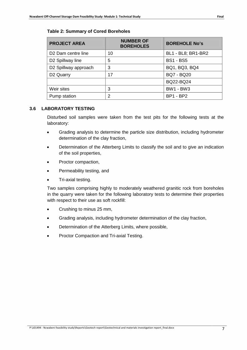
Table 2 summarises the distribution of the core-drilled boreholes. Positions of boreholes were surveyed to an accuracy of 200 mm both horizontally and vertically. These positions are shown on Figure A5.
Ncwabeni Off-Channel Storage Dam Feasibility Study: Module 1: Technical Study Final
P:\J01494 - Ncwabeni feasibility study\Reports\Geotech report\Geotechnical and materials investigation report_final.docx 7
Table 2: Summary of Cored Boreholes
3.6 LABORATORY TESTING
Disturbed soil samples were taken from the test pits for the following tests at the laboratory:
• Grading analysis to determine the particle size distribution, including hydrometer determination of the clay fraction,
• Determination of the Atterberg Limits to classify the soil and to give an indication of the soil properties,
• Proctor compaction,
• Permeability testing, and
• Tri-axial testing.
Two samples comprising highly to moderately weathered granitic rock from boreholes in the quarry were taken for the following laboratory tests to determine their properties with respect to their use as soft rockfill:
• Crushing to minus 25 mm,
• Grading analysis, including hydrometer determination of the clay fraction,
• Determination of the Atterberg Limits, where possible,
• Proctor Compaction and Tri-axial Testing.
PROJECT AREA NUMBER OF BOREHOLES BOREHOLE No’s
D2 Dam centre line 10 BL1 - BL8; BR1-BR2 D2 Spillway line 5 BS1 - BS5 D2 Spillway approach 3 BQ1, BQ3, BQ4 D2 Quarry 17 BQ7 - BQ20 BQ22-BQ24 Weir sites 3 BW1 - BW3 Pump station 2 BP1 - BP2

Ncwabeni Off-Channel Storage Dam Feasibility Study: Module 1: Technical Study Final
P:\J01494 - Ncwabeni feasibility study\Reports\Geotech report\Geotechnical and materials investigation report_final.docx 8
4 GEOLOGY
4.1 GENERAL GEOLOGY
Information on the regional geology was obtained from Sheet 3030 Port Shepstone of the Geological Series of South Africa, at a scale of 1:250 000, while the geology of the surrounding area was mapped by the Council for Geoscience, as shown on Figure A2.
The geology, as inferred from the available maps, shows that the region is generally underlain by granitic rocks of the Oribi Gorge Suite of the Natal Structural and Metamorphic Province of Namibian Age. The geological maps indicate that the periphery of the study area is underlain by diamictite (mainly tillite) of the Dwyka Formation and by sandstones and shales of the Ecca Group of the Karoo Supergroup.
Based on the geological map, the D3 Basin is underlain predominantly by alluvial deposits of quaternary age, which is underlain by the Oribi Gorge Suite. The D2 basin is predominantly underlain by granitic rocks that are weathered to varying depths.
4.2 ORIBI GORGE SUITE
The Oribi Gorge Suite forms part of the Natal metamorphic province. Approximately 1 000 million years ago, subduction and collision along the southern margin of the Kaapvaal Craton produced the rocks of the Natal Metamorphic Province. The rocks were heated and deformed into a mountain range many thousands of kilometres long. Late-syntectonic Oribi Gorge granitoids, represented in the field by very coarse grained porphyritic granite, were emplaced after the cessation of the Margate and Mzumbe terranes and were only subjected to the waning stages of deformation. They were emplaced into and affected by large-scale shear zones associated with the collision of the Natal Metamorphic Province and the Kaapvaal Craton to the north.
4.3 DWYKA TILLITE
South Africa was part of the super continent Gondwana that drifted over the South Pole approximately 300 million years ago. Glacial activity of the region at the time scoured the sandstone and basement rocks beneath the sandstone to produce an extensive glacial pavement. Over a period of 120 million years, the glaciers retreated, depositing the poorly sorted diamictite (mainly tillite) unconformably into the lower part of the Karoo Supergroup.
4.4 ALLUVIAL DEPOSITS
Alluvial deposits, which are of quaternary age, usually comprise a sequence of sands, silts and clays. Climatic changes affect all aspects of a drainage system. The rise and fall of water levels lead to the deposit of sequences of sands, silts and clays. These deposits are usually derived from the weathering of rock types found in the region and transport via water. Alluvial deposits have been identified in the study area, probably from ancient rivers that were present a long time ago.
4.5 COLLUVIAL MATERIALS
Colluvial soils comprising gravels, sands, silts and clays are the products of in situ weathering of the various types of bedrock transported by water and gravity over short distances downslope. These soils occur everywhere except on the alluvium and areas

Ncwabeni Off-Channel Storage Dam Feasibility Study: Module 1: Technical Study Final
P:\J01494 - Ncwabeni feasibility study\Reports\Geotech report\Geotechnical and materials investigation report_final.docx 9
of outcropping rock and are generally too thin (typically less than 3 m) to be shown on the geological map.

Ncwabeni Off-Channel Storage Dam Feasibility Study: Module 1: Technical Study Final
P:\J01494 - Ncwabeni feasibility study\Reports\Geotech report\Geotechnical and materials investigation report_final.docx 10
5 IDENTIFICATION OF POTENTIAL FATAL FLAWS
The pre-feasibility report by the Council for Geoscience reported that one major and several smaller faults appear to intersect the dam centre line on the left flank. Based on that, the first task of this feasibility geotechnical investigation was to determine whether any fatal flaws exist that would render the site unsuitable for the construction of a dam.
The main purpose of the seismic refraction survey was to locate zones of low seismic velocity that are usually associated with deep weathering along fault zones. Such a zone was found along the lower half of the left flank (between Ch 200 m and Ch 320 m on the seismic profile in Figure A5).
Boreholes BL3 and BL4 were drilled to investigate the above zone of low velocity material and the inclined BL3 encountered highly weathered material to a vertical depth of about 22 m, and moderately weathered rock extends beyond the maximum vertical depth of the hole (30 m). The presence of moderately weathered rock extending to over 30 m depth over a 40 m wide zone along the fault zone and the average excavation depth of over 16 m along the length of the centre line have major cost implications for the construction of a concrete dam, but cannot be considered a fatal flaw.
The lack of sufficient quantities of impervious material might be considered a fatal flaw for the construction of a cored embankment dam.

Ncwabeni Off-Channel Storage Dam Feasibility Study: Module 1: Technical Study Final
P:\J01494 - Ncwabeni feasibility study\Reports\Geotech report\Geotechnical and materials investigation report_final.docx 11
6 CONSTRUCTION MATERIALS INVESTIGATION
Various types of dams have to be considered, and therefore the available quantities and properties of different types of construction material had to be investigated. The aim of the construction materials investigation was to locate the volumes of materials as shown in Table 3. These quantities do not take into account that during site investigations it is normal practice to prove twice the volume of material required. The quantities below apply to the D2 site and since the pre-feasibility studies showed the costs for the two alternative sites to be comparable, it was assumed that the quantities for the D3 site will be similar.
Table 3: Approximate Volumes of Construction Material Required
Material Types
Rollcrete (m3)
Zoned Earthfill (m3 )
CFR (m3)
CCR (m3)
ACR (m3)
BCR (m3)
Strong rock 270 000 76 000 380 000 450 000 380 000 360 000 Soft rock 374 000 450 000 320 000 330 000 Filters Semi-pervious 1 052 000 Clay 160 000 160 000 Asphalt 50 000 Bentonite 60 000
Note: CFT: Concrete faced rockfill, CCR: Clay core rockfill, ACR: Asphalt core rockfill, BCR: Bentonite core rockfill
The DWA specification for embankment materials is given in Table 4.
Table 4: DWA Specification for Embankment Materials
PROPERTY EMBANKMENT ZONES
Impervious Semi-pervious Pervious Clay content (%) 10-30 <25 <20 PI (%) 10-30 <10 <5 LL (%) 25-60 <25 <20 LS (%) 6-14 <5 <2 MDD (kg/m3) 1350-1700 1600-1850 1700-2000 OMC (%) 12-25 10-15 8-12 Cohesion (kPa) 20-30 10-15 <10 Friction angle (0) 20-30 30-35 >35 Permeability (m/sec) 1x10⁻⁸ 1x10⁻⁷ 1x10⁻⁵
Ideally, the borrow areas must be located below the full supply level (FSL) within the dam basin. The first areas to be investigated were the spillway approach area and other potential borrow areas within the D2 dam basin. When only limited quantities of pervious and semi-pervious materials were found there, the investigation was extended
Ncwabeni Off-Channel Storage Dam Feasibility Study: Module 1: Technical Study Final
P:\J01494 - Ncwabeni feasibility study\Reports\Geotech report\Geotechnical and materials investigation report_final.docx 12
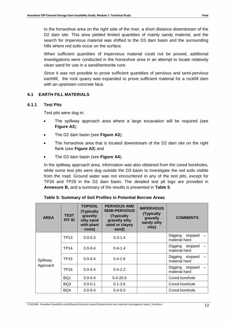
to the horseshoe area on the right side of the river, a short distance downstream of the D2 dam site. This area yielded limited quantities of mainly sandy material, and the search for impervious material was shifted to the D3 dam basin and the surrounding hills where red soils occur on the surface.
When sufficient quantities of impervious material could not be proved, additional investigations were conducted in the horseshoe area in an attempt to locate relatively clean sand for use in a sand/bentonite core.
Since it was not possible to prove sufficient quantities of pervious and semi-pervious earthfill, the rock quarry was expanded to prove sufficient material for a rockfill dam with an upstream concrete face.
6.1 EARTH FILL MATERIALS
6.1.1 Test Pits
Test pits were dug in:
• The spillway approach area where a large excavation will be required (see Figure A3);
• The D2 dam basin (see Figure A3);
• The horseshoe area that is located downstream of the D2 dam site on the right flank (see Figure A3) and
• The D3 dam basin (see Figure A4).
In the spillway approach area, information was also obtained from the cored boreholes, while some test pits were dug outside the D3 basin to investigate the red soils visible from the road. Ground water was not encountered in any of the test pits, except for TP26 and TP29 in the D2 dam basin. The detailed test pit logs are provided in Annexure B, and a summary of the results is presented in Table 5.
Table 5: Summary of Soil Profiles in Potential Borrow Areas
AREA TEST PIT ID
TOPSOIL (Typically gravelly
silty sand with plant
roots)
PERVIOUS AND SEMI-PERVIOUS
(Typically gravelly silty
sand or clayey sand)
IMPERVIOUS (Typically gravelly
sandy silty clay)
COMMENTS
Spillway Approach
TP13 0.0-0.3 0.3-1.4 Digging stopped – material hard
TP14 0.0-0.4 0.4-1.4 Digging stopped – material hard
TP15 0.0-0.4 0.4-2.6 Digging stopped – material hard
TP16 0.0-0.4 0.4-2.2 Digging stopped – material hard
BQ1 0.0-0.4 0.4-20.6 Cored borehole BQ3 0.0-0.1 0.1-3.6 Cored borehole BQ4 0.0-0.4 0.4-6.0 Cored borehole

Ncwabeni Off-Channel Storage Dam Feasibility Study: Module 1: Technical Study Final
P:\J01494 - Ncwabeni feasibility study\Reports\Geotech report\Geotechnical and materials investigation report_final.docx 13
Table 5 Continued: Summary of Soil Profiles in Potential Borrow Areas
AREA TEST PIT ID
TOPSOIL (Typically
gravelly silty sand with
plant roots)
PERVIOUS AND SEMI-PERVIOUS
(Typically gravelly silty
sand or clayey sand)
IMPERVIOUS (Typically gravelly
sandy silty clay)
COMMENTS
Horseshoe area
TP17 0.0-0.7 0.7-2.2 Digging stopped – material hard
TP18 0.0-0.5 0.5-4.2 Maximum reach
TP19 0.0-0.7 0.7-2.7 Digging stopped – material hard
Horseshoe area
TP20 0.0-0.6 0.6-4.1 Digging stopped – material hard
TP21 0.0-0.4 0.4-1.3 1.3-4.0 Maximum reach
TP22 0.0-0.4 0.4-3.4 Digging stopped – material hard
TP23 0.0-0.4 0.4-2.8 Digging stopped – material hard
TP24 0.0-0.4 0.4-3.4 Maximum reach TPH01 0.0-0.6 0.6-4.1 Maximum reach
TPH02 0.0-9.5 0.5-2.0 Digging stopped – material hard
TPH03 0.0-0.6 0.6-3.5 Digging stopped – material hard
TPH04 0.0-0.5 0.5-2.7 Digging stopped – material hard
TPH05 0.0-0.6 0.6-3.2 Digging stopped – material hard
TPH06 0.0-0.4 0.4-3.1 Digging stopped – material hard
D2 Basin
TP25 0.0-0.4 0.5-3.4 Digging stopped – material hard
TP26 0.0-0.4 0.4-1.4 Collapse due to water
TP27 0.0-4.0 Maximum reach
TP28 0.0-2.5 Collapse due to water
RP29 0.0-0.3 0.3-2.0 Refusal TP30 0.0-0.3 0.3-2.3 Refusal
TP31 0.0-0.5 0.5-2.7 Digging stopped – material hard
TP32 0.0-0.4 0.4-1.5 Digging stopped – material hard
TP33 0.0-0.4 0.4-1.6 Digging stopped – material hard
D3 Basin
TP34 0.0-0.3 0.3-1.4 Digging stopped – material hard
TP35 0.0-0.2 0.2-1.6 Digging stopped – material hard
TP36 0.0-0.4 0.4-1.0 1.0-2.5 Digging stopped – material hard
TP37 0.0-0.3 0.3-3.8 0.3-3.3 Digging stopped – material hard
TP38 0.0-0.3 0.5-1.9 0.3-1.5 Digging stopped – material hard

Ncwabeni Off-Channel Storage Dam Feasibility Study: Module 1: Technical Study Final
P:\J01494 - Ncwabeni feasibility study\Reports\Geotech report\Geotechnical and materials investigation report_final.docx 14
Table 5 Continued: Summary of Soil Profiles in Potential Borrow Areas
AREA TEST PIT ID
TOPSOIL (Typically gravelly
silty sand with plant
roots)
PERVIOUS AND SEMI-PERVIOUS
(Typically gravelly silty sand or clayey sand)
IMPERVIOUS (Typically gravelly
sandy silty clay)
COMMENTS
TP39 0.0-0.5 2.2-3.0 0.5-2.2 Digging stopped – material hard
TP40 0.0-0.5 0.5-2.2 2.2-2.9 Digging stopped – material hard
TP41 0.0-0.3 0.3-2.0 Digging stopped – material hard
TP42 0.0-0.3 0.3-0.7 0.7-4.0 Maximum reach
TP43 0.0-0.4 2.0-2.3 0.4-2.0 Digging stopped – material hard
TP44 0.0-0.6 0.6-3.0 Digging stopped – material hard
TP45 0.0-0.5 0.5-3.6 Digging stopped – material hard
TP46 0.0-1.0 1.0-3.3 Digging stopped – material hard
TP47 0.0-0.4 0.4-3.0 Digging stopped – material hard
TP48 0.0-0.08 0.8-2.5 Stopped due to slow progress
TP49 0.0-0.3 0.3-3.9 Maximum reach TP50 0.0-0.2 0.2-3.9 Maximum reach
TP51 0.0-0.3 0.3-2.6 Digging stopped – material hard
TP52 0.0-0.2 0.2-1.1 Digging stopped – material hard
TP53 0.0-0.6 0.6-2.1 Digging stopped – material hard
TP54 0.0-0.5 0.5-1.7 Digging stopped – material hard
TP56 0.0-0.4 0.4-3.0 Digging stopped – material hard
TP46a 0.0-0.6 0.6-2.7 Digging stopped – material hard
TP47a 0.0-0.6 0.6-3.4 Digging stopped – material hard
TP48a 0.0-0.25 0.25-1.3 Digging stopped – material hard
TP49a 0.0-0.7 0.7-2.5 Digging stopped – material hard
TP50a 0.0-0.3 0.3-1.8 Digging stopped – material hard
TP51a 0.0-0.5 0.5-1.9 Digging stopped – material hard
TP52a 0.0-0.8 0.8-2.0 Digging stopped – material hard
TP54a 0.0-0.4 0.4-0.7 Digging stopped – material hard
Ncwabeni Off-Channel Storage Dam Feasibility Study: Module 1: Technical Study Final
P:\J01494 - Ncwabeni feasibility study\Reports\Geotech report\Geotechnical and materials investigation report_final.docx 15
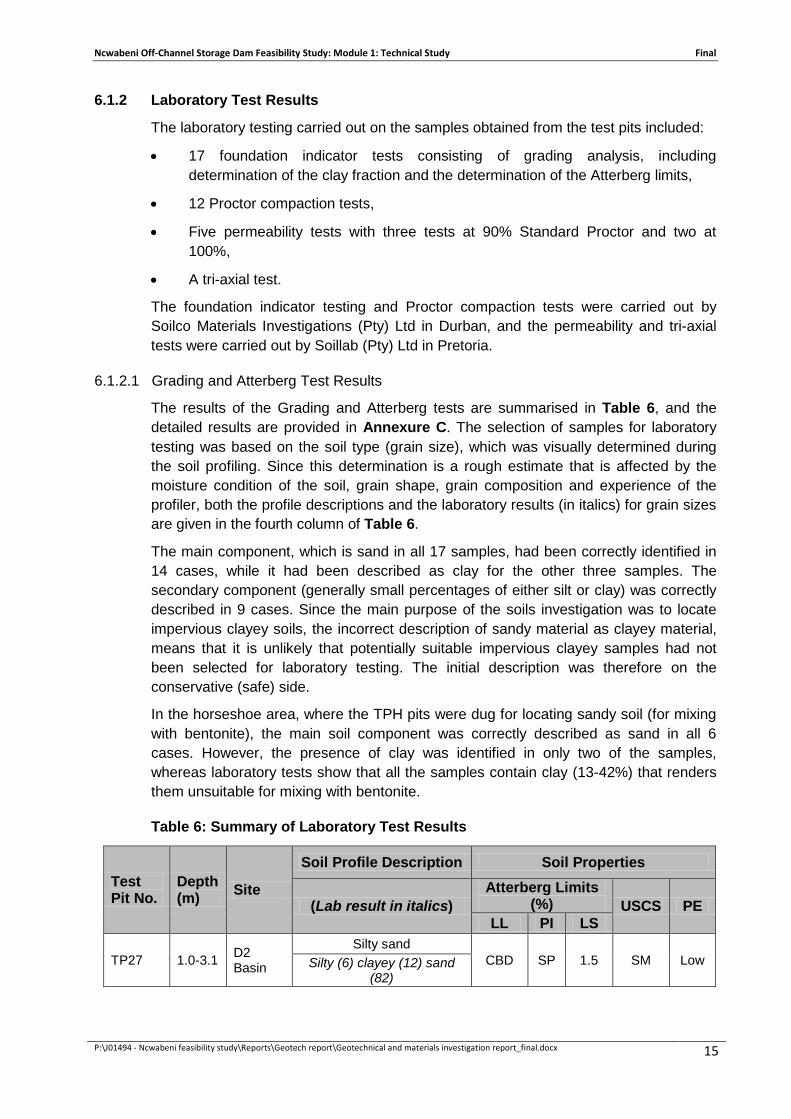
6.1.2 Laboratory Test Results
The laboratory testing carried out on the samples obtained from the test pits included:
• 17 foundation indicator tests consisting of grading analysis, including determination of the clay fraction and the determination of the Atterberg limits,
• 12 Proctor compaction tests,
• Five permeability tests with three tests at 90% Standard Proctor and two at 100%,
• A tri-axial test.
The foundation indicator testing and Proctor compaction tests were carried out by Soilco Materials Investigations (Pty) Ltd in Durban, and the permeability and tri-axial tests were carried out by Soillab (Pty) Ltd in Pretoria.
6.1.2.1 Grading and Atterberg Test Results
The results of the Grading and Atterberg tests are summarised in Table 6, and the detailed results are provided in Annexure C. The selection of samples for laboratory testing was based on the soil type (grain size), which was visually determined during the soil profiling. Since this determination is a rough estimate that is affected by the moisture condition of the soil, grain shape, grain composition and experience of the profiler, both the profile descriptions and the laboratory results (in italics) for grain sizes are given in the fourth column of Table 6.
The main component, which is sand in all 17 samples, had been correctly identified in 14 cases, while it had been described as clay for the other three samples. The secondary component (generally small percentages of either silt or clay) was correctly described in 9 cases. Since the main purpose of the soils investigation was to locate impervious clayey soils, the incorrect description of sandy material as clayey material, means that it is unlikely that potentially suitable impervious clayey samples had not been selected for laboratory testing. The initial description was therefore on the conservative (safe) side.
In the horseshoe area, where the TPH pits were dug for locating sandy soil (for mixing with bentonite), the main soil component was correctly described as sand in all 6 cases. However, the presence of clay was identified in only two of the samples, whereas laboratory tests show that all the samples contain clay (13-42%) that renders them unsuitable for mixing with bentonite.
Table 6: Summary of Laboratory Test Results
Test Pit No.
Depth (m) Site
Soil Profile Description Soil Properties
(Lab result in italics) Atterberg Limits
(%) USCS PE LL PI LS
TP27 1.0-3.1 D2 Basin
Silty sand CBD SP 1.5 SM Low Silty (6) clayey (12) sand
(82)

Ncwabeni Off-Channel Storage Dam Feasibility Study: Module 1: Technical Study Final
P:\J01494 - Ncwabeni feasibility study\Reports\Geotech report\Geotechnical and materials investigation report_final.docx 16
Table 6 Continued: Summary of Laboratory Test Results
Test Pit No.
Depth (m) Site
Soil Profile Description Soil Properties
(Lab result in italics) Atterberg Limits
(%) USCS PE LL PI LS
TP27 3.1-4.0 D2 Basin Gravely silty sand
CBD SP 0.5 SM Low Silty (5) clayey (7) sand (88)
TP30 0.3-1.8 D2 Basin Silty sand
29* 11 5.5 CL Low Clayey (10) silty (23) sand (67)
TP30 1.8-2.3 D2 Basin Gravely silty sand
21 12 6 SC Low Clayey (3) silty (22) sand (75)
TP37 1.1-3.3 D3 Basin Sandy silty clay
CBD NP 0 SM Low Clayey (7) silty (16) sand (77)
TP38 0.3-1.5 D3 Basin Sandy silty clay
23 6 3 SM Low Clayey (14) silty (14) sand (72)
TP42 0.7-2.4 D3 Basin Sandy silty clay
27 14 7 CL Low Clayey (22) silty (23) sand (55)
TP42 2.4-4.0 D3 Basin Sandy silty clay
36 12 6 SM Low Clayey (2) silty (39) sand (59)
TP43 0.4-2.0 D3 Basin Sandy silty clay
27 9 4.5 SC Low Clayey (11) silty (20) sand (69)
TP HO1 0.6 - 2.4 Horseshoe Area
Gravelly clayey silty sand 24 8 4 SC Low Clayey (10) silty (14) sand (78)
TP HO1 2.4 - 4.1 Horseshoe Area
Gravelly silty sand 28 13 6.5 CL Low
Clayey (13) silty (16) sand (71)
TP HO2 0.5 - 2.0 Horseshoe Area
Clayey silty sand 35 15 7.5 CL Low
Silty (12) clayey (38) sand (50)
TP HO5 0.6 - 2.1 Horseshoe Area
Gravely silty sand 33 13 6.5 CL Low
Silty (11) clayey (26) sand (63)
TP HO5 2.1 - 3.2 Horseshoe Area
Gravelly silty sand 27 12 6 CL Low Silty (11) clayey (19) sand (70)
TP HO6 0.4 - 1.2 Horseshoe Area
Clayey silty sand 37 17 8.5 CH Low Silty (11) clayey (42) sand (47)
TP HO6 1.2 - 2.1 Horseshoe Area
Gravelly silty sand 32 12 6 CL Low
Silty (11) clayey (26) sand (63) Legend LL = Liquid Limit
PI = Plasticity Index
LS = Linear Shrinkage
PE = Potential Expansiveness
USCS = Unified Soil Classification System
SP = Not Plastic
* Bold text shows suitability as impervious core

Ncwabeni Off-Channel Storage Dam Feasibility Study: Module 1: Technical Study Final
P:\J01494 - Ncwabeni feasibility study\Reports\Geotech report\Geotechnical and materials investigation report_final.docx 17
6.1.2.2 Proctor Compaction Test Results
Proctor compaction tests were done on 14 samples that are considered representative of the material encountered in the investigated areas. The test results are summarised in Table 7 below. The detailed results are included in Annexure C.
Table 7: Summary of Proctor Compaction Results
Proctor Compaction Test Results
Inspection Pit No.
Depth (m) Site
Soil Profile Description USCS
Proctor Compaction
(Lab result in italics) MDD (kg/m3)
OMC (%)
TP27 1.0-3.1 D2 Basin Silty sand
SM 1975 11 Silty (6) clayey (12) sand (82)
TP27 3.1-4.0 D2 Basin Gravely silty sand
SM 2021 9.8 Silty (5) clayey (7) sand (88)
TP33 1.6-2.4 D2 Basin Sandy silty clay
SC 1750 15.2 Clayey (21) silty (21) sand (58)
TP42 0.7-2.4 D3 Basin Sandy silty clay
CL 1675 18 Clayey (22) silty (23) sand (55)
TP42 2.4-4.0 D3 Basin Sandy silty clay
CL 1693 18.4 Clayey (2) silty (39) sand (59)
TPH01 0.6 - 2.4 Horseshoe Area
Gravelly silty sand SC 2039 9.1 Clayey (13) silty (16)
sand (71)
TPH01 2.4 - 4.1 Horseshoe Area
Gravelly silty sand CL 1915 13.7 Clayey (13) silty (16)
sand (71)
TPH02 0.5 - 2.0 Horseshoe Area
Clayey silty sand CL 1730 16.2 Silty (12) clayey (38)
sand (50)
TPH05 0.6 - 2.1 Horseshoe Area
Gravely silty sand CL 1869 13.2 Silty (11) clayey (26)
sand (63)
TPH05 2.1 - 3.2 Horseshoe Area
Gravelly silty sand CL 1927 11.2 Silty (11) clayey (19)
sand (70)
TPH06 0.4 - 1.2 Horseshoe Area
Clayey silty sand CH 1626 19.6 Silty (11) clayey (42)
sand (47)
TPH06 1.2 - 2.1 Horseshoe Area
Gravelly silty sand CL 1704 14 Silty (11) clayey (26)
sand (63) Legend: USCS = Unified Soil Classification System MDD = Maximum Dry Density OMC = Optimum Moisture Content

Ncwabeni Off-Channel Storage Dam Feasibility Study: Module 1: Technical Study Final
P:\J01494 - Ncwabeni feasibility study\Reports\Geotech report\Geotechnical and materials investigation report_final.docx 18
6.1.2.3 Permeability Test Results
Clayey soils from TP33, TP42 and TPH06 were sampled to determine the coefficient of permeability and thus the suitability of this material for use as impervious core. Permeability values of slower than 1 x 10⁻⁷ m/s are considered suitable for impervious core material. The results of the permeability testing that were carried out at Proctor density are tabulated in Table 8.
Table 8: Summary of Permeability Test Results
Sample No. Test Pit ID.
Depth (m) USCS
Max Proctor
Dry Density (kg/m3)
Optimum Moisture Content
(%)
Head of Water (cm)
Coefficient of
Permeability (m/s)
L/NO9472 TP33 1.6-2.4 SC 1750 15.2 102 1.155x10⁻⁷ L/NO9475 TP42 0.7-2.4 CL 1675 18 falling 1.650x10⁻¹⁰ L/NO9476 TP42 2.4-4.0 CL 1693 18.4 falling 2.553x10⁻¹⁰ F957 TPH06 0.4-1.2 CH 1615 19.8 falling 4.7x10⁻¹¹
F958 TPH06 1.2-2.1 CL 1692 14.8 falling 7.9x10⁻¹²
6.1.2.4 Consolidated Undrained Triaxial Test Results
One sample of sandy silty clay (CL) from TP42 (0.7-2.4 m) was taken for triaxial testing. The testing was done on a remoulded sample compacted to 90% Proctor at Optimum Moisture Content and then saturated. A summary of results for the tri-axial test carried out is provided in Table 9.
Table 9: Summary of CU Triaxial Test Results
Sample ID
TP ID
Depth (m) USCS Moisture
State Rate of
Compression (mm/m)
Sample State
Cohesion (kPa)
Angle of Internal Friction
(degrees)
L/No. 9475 TP42 0.7-
2.4 CL saturated 0.59
Remoulded to 90% Proctor
MDD and OMC
0 26.6
The above results appear to be incorrect, since a CL material containing 22% clay must have some cohesion.
6.1.3 Available Quantities of Earth Fill Material
6.1.3.1 Gugamela Site (D3)
Impervious Core Material Only 10 of the 30 test pits excavated in the D3 basin encountered soils described as sandy silty clay. Laboratory tests were conducted on samples from four of these test pits, and only two test pits (TP 42 and TP 43) gave material that is marginally suitable as impervious core. The findings indicate that the D3 basin is underlain predominantly by gravelly silty sand that is considered unsuitable for use as impervious core. Based on the previous DWA investigations and the description

Ncwabeni Off-Channel Storage Dam Feasibility Study: Module 1: Technical Study Final
P:\J01494 - Ncwabeni feasibility study\Reports\Geotech report\Geotechnical and materials investigation report_final.docx 19
of the soil profiles, this result was not expected since the DWA reported large quantities of suitable material.
The total volume of impervious material that could be proved in the D3 basin is about 96 000 m3. This volume represents a shortfall of 224 000 m3 from the 2 x 160 000 m3 required for the clay core of an embankment dam (see Table 3).
Semi-Pervious Embankment Material
Thirty test pits dug in the D3 basin and surroundings showed variable sandy and gravelly material and occasional clayey material with an average thickness of about 2.7 m that is suitable as semi-pervious material. The estimated volume from this area is 400 000 m3. This represents a shortfall of 1,7 million m3 from the 2 x 1 052 000 m3 needed for an embankment dam (Table 3).
6.1.3.2 Ncwabeni Site (D2)
Impervious Core Material
In the D2 dam basin, only two test pits encountered marginally suitable core material based on laboratory tests and the application of the Department Water Affairs (DWA) specification. The volume of impervious material available from this area is about 3 000 m3.
Fourteen test pits were dug in the horseshoe area outside the D2 dam basin, of which only four showed marginally suitable impervious material. The total available volume is about 5 000 m3.
Should it be considered to use all the impervious material that could be proved in the D3 basin, the D2 basin and the horseshoe (about 96 000 m3, 3 000 m3 and 5 000 m3 respectively) then at least another 216 000 m3 of impervious material will have to be proved to obtain 2 x 160 000 m3 for the clay core of an embankment dam (see Table 3).
Semi-Pervious Embankment Material
Four test pits and three boreholes in the spillway approach area showed clayey sand (completely weathered granite to depths of 3.6-20.6 m). This material was not tested, but is considered suitable as semi-pervious embankment material. Excavation of the material might be difficult due to the steep topography and variable thickness of material. The estimated volume from this area is 8 000 m3.
Nine test pits dug in the D2 basin showed an average thickness of 2.7 m of sand and gravelly sand that is considered suitable for use as semi-pervious embankment material. The estimated volume from this area is 105 000 m3.
Fourteen test pits dug in the horseshoe area showed variable sandy material to an average depth of about 2.7 m. Most of these materials may be suitable for use as semi-pervious embankment material. The estimated volume from this area is 280 000 m3.
Thirty test pits dug in the D3 basin and surroundings showed variable sandy and gravelly material and occasional clayey material with an average thickness of about 2.7 m that might be suitable as semi-pervious material. The estimated volume from this area is 400 000 m3.

Ncwabeni Off-Channel Storage Dam Feasibility Study: Module 1: Technical Study Final
P:\J01494 - Ncwabeni feasibility study\Reports\Geotech report\Geotechnical and materials investigation report_final.docx 20
If the total proven volumes (793 000m3) of semi-pervious materials from the above three areas are added together, it will still be necessary to prove another 1 200 000m3 of material to reach the 2 x 1 052 000 m3 needed for an embankment dam (Table 3).
6.2 ROCK MATERIALS
6.2.1 Cored Boreholes
Seventeen boreholes (BQ7 – BQ20 and BQ22 – BQ24) were drilled in an area proposed for a rockfill quarry (see Figure A6). The borehole results summarised in Table 10 may differ slightly from the detailed borehole logs contained in Annexure D because ranges of degrees of weathering (e.g. highly to moderately) as given in the logs have been changed to single descriptors, and depths have been rounded to the nearest 0.2 m. This was done to facilitate drafting of the geological longitudinal sections as shown on Figure A7. The core photographs are contained in Annexure E.
Table 10: Summary of Borehole Logs in the proposed quarry area in the D2 Basin
Borehole number
Topsoil and residual soil (Depth - m)
Completely Weathered (Depth - m)
Highly weathered (Depth - m)
Moderately weathered (Depth - m)
Slightly weathered (Depth - m)
Un-weathered (Depth - m)
BQ 7 0.0-3.6 3.6-4.4 4.4-6.4 6.4-7.2
7.2-12.36 BQ 8 0.0-1.0 1.0-6.6 6.6-12.6 12.6-13.8 13.8-18.4 18.4-28.51 BQ 9 0.0-2.0 2.0-26.4
26.4-27.6 27.6-28.0 28.0-29.91
BQ 10 0.0-0.6 0.6-10.0 10.0-17.4
17.4-29.70 BQ 11 0.0-3.4 3.4-6.0 6.0-7.2 7.2-8.0 8.0-18.0 18.0-25.48 BQ 12 0.0-0.80
2.4-3.2 0.80-2.4 3.2-25.41
BQ 13 0.0-3.0 3.0-3.6 3.6-4.4
4.4-6.2 6.2-29.94 BQ 14 0.0-3.8 3.8-5.6 5.6-9.4
9.4-10.0 10.0-30.09
BQ 15 0.0-0.8 0.8-7.6 7.6-8.6
8.6-10.0 13.0-18.25 10.0-10.4 10.4-10.6
10.6-12.0 12.0-13.0 BQ 16 0.0-0.2 0.2-1.4 1.4-2.8
2.8-3.6 3.6-9.32
BQ 17 0.0-3.2 3.2-4.2 4.2-8.4 8.4-9.6
9.6-16.33 BQ 18 0.0-1.2 1.4 4.0-19.0 19.0-21.4 21.4-27.01 - BQ 19 0.0-2.2
2.2-10.97
BQ 20 0.0-3.0
3.0-5.6
5.6-30.3
BQ22 0.0-1.6 1.6-5.0 5.0-16.4 16.4-18.6 18.6-27.29
BQ23 0.0-1.0
1.0-20.6 22.8-27.2
20.6-22.8 28.4-30.05
27.2-28.4
BQ24 0.0-0.6 0.6-2.8 2.8-18.6 18.6-20.4 20.4-21.6 21.6-27.35

Ncwabeni Off-Channel Storage Dam Feasibility Study: Module 1: Technical Study Final
P:\J01494 - Ncwabeni feasibility study\Reports\Geotech report\Geotechnical and materials investigation report_final.docx 21
6.2.2 Laboratory Testing
Two samples, one of which comprised highly weathered cores and the other completely weathered cores from various boreholes were submitted for laboratory testing. The samples were crushed to the minus 25 mm size and subjected to Grading, Atterberg, Proctor and Triaxial testing. For the Proctor and Triaxial tests, the minus 0.85 mm fraction was used, while for the Triaxial test, a mixture of the two weathered samples was used. The results are shown in Table 11.
Table 11: Summary of laboratory tests on crushed rock cores
Sample Origin Completely weathered cores Highly weathered cores Laboratory Number 3493 3494 Grading description Clayey (1%), silty (5%) sand
(96%) Clayey (1%), silty (3%)
sand (96%) LL (%) 29 Non plastic PI (%) 6 Non plastic LS (%) 3 1.5 PE Low Low Proctor MDD (kg/m3) 1897 1883 OMC (%) 6.5 6.4 Cohesion - total (kPa) 128.9 Friction angle - total (degrees) 26.1 Cohesion - effective (kPa) 107.8 Friction angle - effective (degrees) 33.8
The hard rockfill was not tested, but shear strength values of c = 0 and phi = 42 degrees can be assumed. The laboratory results for the soft rockfill gave values for c (effective) = 107 kPa and phi (effective) of 33.8 degrees. However, from the grading it appears that the rock, when broken down, comprises almost completely of sand-size particles. For this material, a cohesion of zero and friction angle of 38 degrees would seem more appropriate.
6.2.3 Available Volumes of Rockfill Material
Moderately weathered to unweathered granite occurs everywhere in the D2 basin, but in most areas it is covered by variable thicknesses of topsoil, residual granite soil, completely weathered granite and highly weathered granite.
The moderately to unweathered granite is suitable as conventional hard rockfill, and large quantities of this material are available once the overburden has been removed. The hard rock occurs mainly in and alongside the course of the Ncwabeni River, while the valley sides are underlain by variable thicknesses of soft rock.
Due to the presence of slightly weathered and unweathered granite in the riverbed, a quarry area adjacent to the Ncwabeni River was investigated. Development of a quarry in this area will require diversion of the river or extraction of material in wet conditions from the low-lying areas.

Ncwabeni Off-Channel Storage Dam Feasibility Study: Module 1: Technical Study Final
P:\J01494 - Ncwabeni feasibility study\Reports\Geotech report\Geotechnical and materials investigation report_final.docx 22
To avoid wastage of large volumes of overburden, consideration was given to the use of soft rockfill (completely and highly weathered granite) in parts (about 50%) of a rockfill embankment while conventional hard rockfill is to be used in critical zones (upstream shell and outside zones). The ratio of soft to hard material available from the proposed quarry depends on the volume requirements, i.e. a small quantity of hard rock can be obtained from areas close to the river, resulting in the production of a relatively small volume of soft rock, whereas a large volume of hard rock will require larger volumes of soft excavation.
A temporary diversion weir can be constructed in the Ncwabeni River, just north of BQ17, and a diversion canal can be excavated to pass between BQ13 and BQ14 and end in the river channel between BQ8 and BQ7 (see Figure A6).
Quarry area A (with a surface area of about 30 000 m2) between BQ17, BQ11, BQ18 and a point about 100 m to the northwest of BQ20, can be developed to produce about 80 000 m3 of soft rockfill.
If a bulking factor is taken into account, about 40 000 m3 of hard rockfill can be obtained for every metre depth excavated below the soft zone. If the excavation is taken to a depth of 6m below river bed, 240 000 m3 of hard rockfill is obtained here. (Based on the topography and the established weathering patterns, it appears possible to extend Quarry A towards the east, in which case the above volumes can be increased by about 20% to obtain a total volume of 288 000 m3.) Provision will have to be made for the pumping of groundwater seeping into the quarry.
Quarry area B (area of about 20 000 m2) around BQ9, BQ8, BQ10 and BQ21 can be quarried to produce about 250 000 m3 of soft rockfill. If the excavation is taken to a depth of 6 m below river bed level, then about 400 000 m3 of hard rockfill can be obtained. (Based on the topography and the established weathering patterns, it appears possible to extend Quarry B towards the south-west, in which case the volume of rockfill can be increased to 600 000 m3.)
The drilling investigation proved about 330 000 m3 of soft rockfill and 640 000 m3 of hard rockfill, the total of 970 000 m3, which is 130% of the required 754 000 m3 shown in to Table 3. Revised quantities for hard rockfill (406 974 m3) and soft rockfill (239 675 m3) obtained from the Module 1:Technical Study, are slightly less than the provisional volumes assumed at the time of the materials investigation. Based on the revised figures, about 150% of the required volume had therefore been proved.
The practice to prove 200% of the required construction material volumes during a site investigation is an arbitrary safety factor that had been established for the investigation of soils borrrow areas to take account of the variability of soil properties over short distances. In these proposed rockfill quarries, the ratio of “soft” to “hard” rockfill may not be exactly as predicted from the borehole results, and might result in the production of slightly smaller or larger volumes of “soft” rock. However, the total volume of rockfill will not change significantly. A proven volume of 150% of the required volume is therefore considered to offer a sufficiently large margin of safety. However, an additional margin of safety is available by considering lateral extension of the quarries, and in so doing, obtains an additional volume of about 240 m3 of hard rockfill.

Ncwabeni Off-Channel Storage Dam Feasibility Study: Module 1: Technical Study Final
P:\J01494 - Ncwabeni feasibility study\Reports\Geotech report\Geotechnical and materials investigation report_final.docx 23
7 GEOTECHNICAL INVESTIGATIONS
Geotechnical investigations were conducted at the following locations:
• along the D2 dam centre line;
• along the proposed alignment for a side spillway on the upper left flank;
• at two alternative weir sites on the Mzimkulu River; and
• at two alternative pumping station sites. Investigations aimed to provide founding levels for the various structures, including various types of dams.
Packer permeability tests were undertaken to determine the need for grouting below the dam.
7.1 DAM CENTRE LINE
The position for the dam centre line was selected based on the topography, particularly along the ridge on the left flank. The first step was to clear the bush along the centre line to allow access for the seismic investigation crew and the core drilling rigs. Due to the thick bush and dense undergrowth, the most economical method of bush clearing was by means of a 20-ton tracked excavator. While working along the centre line, the excavator was also used to dig test pits.
7.1.1 Seismic Refraction Survey
Due to the very steep topography of the right flank, the seismic survey could only be conducted along the 400 m length of the left flank (see seismic profile on Figure A5 and the detailed report in Annexure F).
A low seismic velocity surface layer is typically 2-3 m thick, and may be interpreted as colluvial materials or completely weathered granite. This is followed by material with a velocity in excess of 1000 m/s, that may be interpreted as a progression of completely to moderately weathered granite. This layer grades fairly sharply into seismic basement, comprising fractured, slightly weathered to unweathered granite where the velocity exceeds 2 500 m/s. However, this transition depth is highly variable from less than 5 m near the river and at the top of the left flank to more than 15 m in the middle parts of the left flank. These deep low velocity zones might represent fractured and deeply weathered zones along fault lines.
The seismic refraction surveys indicated the positions of anomalous areas where cored boreholes could be located, and assisted with the interpretation of geological conditions between boreholes.
7.1.2 Test Pits
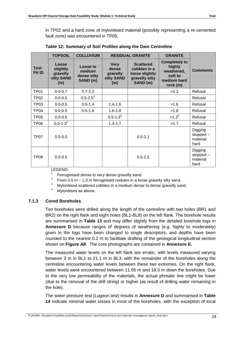
Eight test pits were excavated along the proposed dam centre line on the left flank of the Ncwabeni River (see Figure A3). Five of these were excavated in depressions where it was expected that fault or shear zones may have caused deeper weathering that might be associated with thicker horizons of soft soil near ground surface. However, this was not the case. The soil profiles are summarised in Table 12.
Refusal depths of the 20-ton excavator were surprisingly shallow, indicating very stiff colluvial or residual soils at depths of 1.3-2.5 m. A ferruginised layer was encountered
Ncwabeni Off-Channel Storage Dam Feasibility Study: Module 1: Technical Study Final
P:\J01494 - Ncwabeni feasibility study\Reports\Geotech report\Geotechnical and materials investigation report_final.docx 24
in TP02 and a hard zone of mylonitised material (possibly representing a re-cemented fault zone) was encountered in TP05.
Table 12: Summary of Soil Profiles along the Dam Centreline
Test Pit ID
TOPSOIL COLLUVIUM RESIDUAL GRANITE GRANITE
Comments Loose slightly gravelly
silty SAND (m)
Loose to medium
dense silty SAND (m)
Very dense
gravelly silty SAND
(m)
Scattered cobbles in a
loose slightly gravelly silty
SAND (m)
Completely to highly
weathered, soft to
medium hard rock (m)
TP01 0.0-0.7 0.7-2.2
>2.2 Refusal TP02 0.0-0.5 0.5-2.51
Refusal
TP03 0.0-0.5 0.5-1.4 1.4-1.6
>1.6 Refusal TP04 0.0-0.5 0.5-1.6 1.6-1.8
>1.8 Refusal
TP05 0.0-0.5
0.5-1.33
>1.34 Refusal TP06 0.0-1.32
1.3-1.7
>1.7 Refusal
TP07 0.0-0.5
0.5-2.1
Digging stopped – material hard
TP08 0.0-0.5
0.5-1.5
Digging stopped – material hard
LEGEND: 1 Ferruginised dense to very dense gravelly sand. 2 From 0.5 m – 1.3 m ferruginised nodules in a loose gravelly silty sand. 3 Mylonitised scattered cobbles in a medium dense to dense gravelly sand. 4 Mylonitised as above.
7.1.3 Cored Boreholes
Ten boreholes were drilled along the length of the centreline with two holes (BR1 and BR2) on the right flank and eight holes (BL1-BL8) on the left flank. The borehole results are summarised in Table 13 and may differ slightly from the detailed borehole logs in Annexure D because ranges of degrees of weathering (e.g. highly to moderately) given in the logs have been changed to single descriptors, and depths have been rounded to the nearest 0.2 m to facilitate drafting of the geological longitudinal section shown on Figure A8. The core photographs are contained in Annexure E.
The measured water levels on the left flank are erratic, with levels measured varying between 3 m in BL1 to 21.1 m in BL3, with the remainder of the boreholes along the centreline encountering water levels between these two extremes. On the right flank, water levels were encountered between 11.95 m and 18.3 m down the boreholes. Due to the very low permeability of the materials, the actual phreatic line might be lower (due to the removal of the drill string) or higher (as result of drilling water remaining in the hole).
The water pressure test (Lugeon test) results in Annexure D and summarised in Table 14 indicate minimal water losses in most of the boreholes, with the exception of local

Ncwabeni Off-Channel Storage Dam Feasibility Study: Module 1: Technical Study Final
P:\J01494 - Ncwabeni feasibility study\Reports\Geotech report\Geotechnical and materials investigation report_final.docx 25
higher water losses in some of the holes where poor core recovery and lower Rock Quality Designation (RQD) values were recorded.
Table 13: Summary of Borehole Logs along the Dam Centre line
Borehole Number (inclination)
Material type/ degree of weathering
Topsoil and residual granite
Completely weathered rock (m)
Highly weathered rock (m)
Moderately weathered rock (m)
Slightly weathered rock (m)
Un-weathered rock (m)
Water level (29/11/2011) (depth in m)
BL 1 (60) 0.0 –2.8
2.84-4.0 4.0-6.2 6.2-30.19 3.03 BL 2 (90) 0.0-2 2.0-4.8 4.8-6.2 6.2-11.0 11.0-14.20 14.20-18.0 16.6 BL 3 (60) 0.0-3.6 3.6-4.0 4.0-23.6 23.6-35.4
21.1
BL 4 (90) 0.0-0.8 0.8-1.8 1.8-14.6 14.6-16.2 16.2-18.2 18.2-21.61 16.7 BL 5 (60) 0.0-3.0 3.0-4.4 4.4-17.4
17.4-20.0 20.0-24.24 14.9
BL 6 (90) 0.0-2.0 2.0-3.4 3.4-11.2 14.4-14.8 11.2-14.4 14.8-23.8 15.4
BL 7 (90) 0.0-11.0
11.0-13.8 15.4-16.0
13.8-15.4 16.0-30.0 16.35
BL 8 (90) 0.0-1.0 1.0-3.2 3.2-14.8 14.8-15.0
15.0-20.59 15.5
BR 1 (90) 0.0-1.6 1.6-2.8 6.2-7.8
2.8-6.2 7.8-14.4
18.4-19.0
14.4-18.4 19.0-29.95 18.3
BR 2 (60) 0.0-2.0
2.0-19.6 19.6-26.6 26.6-30.2
11.95 Table 14: Summary of water test results
BH No. LUGEON VALUES
>10 (actual lugeons) 10 - 4 4 - 1 <1 Depth in m Depth in m Depth in m Depth in m
BL1 6.00 – 9.03(31) 1.50 – 6.00
9.03 – 30.19 BL2 9.00 – 12.50 1.50 – 9.00
BL3 21.00 – 24.12 (11) 25.50 – 35.40 1.50 – 21.14
24.00 – 25.62 BL4 1.50 – 20.91
BL5 12.00 – 18.24 6.00 – 8.79 1.5 – 5.91
9.00 – 11.92 18.00 – 24.24
BL6 1.55 – 2.90 (165) 1.90 – 23.70
BL7 15.00 – 17.81 1.55 – 15.12
18.00 – 30.00 BL8 1.50 – 20.59
BR1 6.00 – 8.95
18.00 – 20.95 12.00 – 14.95
1.50 – 5.95 9.00 – 11.95
15.00 – 17.95 21.00 – 29.95
BR2 12.00 – 14.79 (23) 18.00 – 21.29 (13)
1.50 – 11.80
15.00 – 17.77 21.00 – 30.29
Ncwabeni Off-Channel Storage Dam Feasibility Study: Module 1: Technical Study Final
P:\J01494 - Ncwabeni feasibility study\Reports\Geotech report\Geotechnical and materials investigation report_final.docx 26
7.1.4 Founding Conditions for Alternative Dam Types
The shell of an earth embankment is typically founded on material with low organic content and low compressibility, and with shear strength similar to the dam wall material. This means that the ± 0.5 m thick layer of topsoil and zones of loose colluvium have to be removed and that founding will take place on medium-dense colluvium or on very dense residual granite at depths of 0.5-1.3 m. At some places it might be necessary to compact the upper layer of colluvium in order to obtain suitable founding conditions.
The shell of a rockfill embankment is typically founded on material with low organic content and low compressibility, and with shear strength similar to the dam wall material. This means that a 2.0-4.8 m thick layer of topsoil and colluvium has to be removed and that founding will take place on completely or highly weathered granite. In the case of a concrete faced rockfill (CFR) dam, founding of the plinth will require material with either low permeability or good groutability. Lugeon water pressure tests show that this depth corresponds with the depth of excavation for the rockfill shells.
The clay core of an earthfill or rockfill dam is normally founded on material that is either sufficiently impervious or can be rendered impervious by means of grouting. Water pressure (Lugeon) tests in boreholes confirmed that the water loss is minimal below the depth at which the earthfill shells are to be founded.
A concrete gravity dam is normally founded on good quality rock with a minimum Rock Mass rating of 50, giving it an E-value of at least 10 GPa and with shear strength parameters along the most critically orientated discontinuities of C = 250 kPa and φ = 34 degrees.
The recommended excavation depths at borehole positions are listed in Table 15 and shown on Figure A8 in Annexure A.
Table 15: Excavation Depths for Various Dam Components
BH No.
SECTION SHELL CUT-OFF CONCRETE (m) EARTHFILL
(m) ROCKFILL
(m) EARTH
CORE (m) PLINTH
(m) BL1 River
section 2.2 2.84 2.84 2.84 4
BL2 2 4.84 2.0 4.84 11 BL3 2.2 4.05 3.5 4 26+ BL4 Left
flank 1.8 1.8 1.8 1.8 16.2
BL5 2.2 4.4 3.0 4.4 17.4 BL6 2 3.3 2.1 3.3 14.8 BL7 1.8 4.0 1.7 11.0 13.8 BL8 2 3.3 2.2 3.3 15 BR1 Right
flank 1.5 2.84 1.5 2.84 14.35
BR2 2 2.1 2.1 2.1 26.6
The layers of weathered rock below the recommended core trench depth contain joints that are generally tight, but five of the boreholes contain sections with Lugeon values of

Ncwabeni Off-Channel Storage Dam Feasibility Study: Module 1: Technical Study Final
P:\J01494 - Ncwabeni feasibility study\Reports\Geotech report\Geotechnical and materials investigation report_final.docx 27
between 4 and 10, while four of the holes contain sections with Lugeon values of above 10. In the zone 6-24 m below ground level, Lugeon values of above 4 have been recorded. Curtain grouting will thus have to be done below the dam foundation to depths of 20 m on the flanks and about 40 m in the river section.
It must be noted that the above recommendations apply to the dam reference line that roughly corresponds with the alignment of a central earth core. However, the plinth for an upstream faced rockfill dam will be located a considerable distance upstream of the dam reference line, and for the design of this type of dam, additional geotechnical investigations will have to be conducted to determine the founding levels and grouting requirements.
7.2 SPILLWAY AND RISING MAIN
For an embankment dam alternative, a side spillway with chute leading to the Mzimkulu River is proposed. This alignment was investigated by means of a seismic refraction survey, test pits and cored boreholes.
It was assumed that the rising main will be located below or adjacent to the spillway chute and that the geotechnical information along the spillway line would apply.
7.2.1 Seismic Refraction Survey
A seismic refraction traverse was conducted along the upper 200 m length of the proposed spillway chute (see seismic profile on Figure A5 and the detailed report in Annexure F). The last part to the Mzimkulu River was too steep for access.
A low seismic velocity surface layer is typically 2-3 m thick and may be interpreted as colluvial or alluvial materials or completely weathered granite. This is followed by material with a velocity in excess of 1000 m/s that may be interpreted as a progression of completely to moderately weathered granite. This layer grades fairly sharply into seismic basement comprising fractured, slightly weathered to unweathered granite where the velocity exceeds 2 500 m/s. However, this transition depth is highly variable. Deep low velocity zones might represent fractured and deeply weathered zones along fault lines.
The seismic refraction surveys indicated the positions of anomalous areas where cored boreholes must be located, and assisted with the interpretation of geological conditions between boreholes.
7.2.2 Test Pits
Four test pits were excavated along the spillway line to determine the founding conditions (see Figure A3). The profiles of the test pits are summarized in Table 16. No groundwater was encountered in any of the test pits excavated along the spillway. TP 11 encountered alluvial sand to a depth of more than 3 m indicating the presence of an old stream channel.
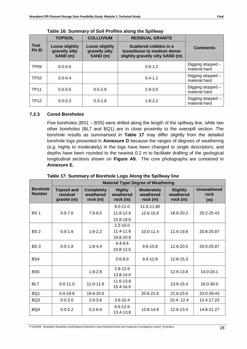
Ncwabeni Off-Channel Storage Dam Feasibility Study: Module 1: Technical Study Final
P:\J01494 - Ncwabeni feasibility study\Reports\Geotech report\Geotechnical and materials investigation report_final.docx 28
Table 16: Summary of Soil Profiles along the Spillway
Test Pit ID
TOPSOIL COLLUVIUM RESIDUAL GRANITE
Comments Loose slightly gravelly silty
SAND (m)
Loose slightly gravelly silty
SAND (m)
Scattered cobbles in a loose/loose to medium dense
slightly gravelly silty SAND (m)
TP09 0.0-0.5
0.5-1.2 Digging stopped – material hard
TP10 0.0-0.4
0.4-1.1 Digging stopped – material hard
TP11 0.0-0.5 0.5-2.9 2.9-3.0 Digging stopped – material hard
TP12 0.0-0.3 0.3-1.8 1.8-2.2 Digging stopped – material hard
7.2.3 Cored Boreholes
Five boreholes (BS1 – BS5) were drilled along the length of the spillway line, while two other boreholes (BL7 and BQ1) are in close proximity to the overspill section. The borehole results as summarised in Table 17 may differ slightly from the detailed borehole logs presented in Annexure D because the ranges of degrees of weathering (e.g. highly to moderately) in the logs have been changed to single descriptors, and depths have been rounded to the nearest 0.2 m to facilitate drafting of the geological longitudinal sections shown on Figure A9. The core photographs are contained in Annexure E.
Table 17: Summary of Borehole Logs Along the Spillway line
Borehole Number
Material Type/ Degree of Weathering Topsoil and
residual granite (m)
Completely weathered rock (m)
Highly weathered rock (m)
Moderately weathered rock (m)
Slightly weathered rock (m)
Unweathered rock (m)
BS 1 0.0-7.6 7.6-8.0 8.0-11.0 11.0-11.80
18.6-20.2 20.2-25.43 11.8-12.6 12.6-15.8 15.8-18.6
BS 2 0.0-1.6 1.6-2.2 2.2-10.0
10.0-11.4 11.6-19.8 20.8-25.87 11.4-11.6 19.8-20.8
BS 3 0.0-1.8 1.8-4.4 4.4-9.6
9.6-10.8 12.6-20.0 20.0-25.87 10.8-12.6
BS4
0.6-9.0 9.0-12.8 12.8-15.3
BS5
1.8-2.8 2.8-12.6
12.6-13.8 14.0-20.1
13.8-14.0
BL7 0.0-11.0 11.0-11.6 11.6-13.8 15.4-16.0
13.8-15.4 16.0-30.0
BQ1 0.0-19.6 19.6-20.6 20.6-21.6 21.6-23.0 23.0-28.43 BQ3 0.0-2.0 2.0-3.6 3.6-10.4 10.4- 12.4 12.4-17.23
BQ4 0.0-5.2 5.2-6.6 6.6-12.6 13.4-13.8
13.8-14.8 12.6-13.4 14.8-21.27

Ncwabeni Off-Channel Storage Dam Feasibility Study: Module 1: Technical Study Final
P:\J01494 - Ncwabeni feasibility study\Reports\Geotech report\Geotechnical and materials investigation report_final.docx 29
7.2.4 Founding Conditions
The spillway overflow section and return channel will have to be concrete-lined to prevent erosion of the deeply weathered granite. The concrete lining can be founded on highly weathered granite but must be designed to span across local zones of completely weathered rock that are likely to occur at or below the recommended founding levels. The recommended founding levels at the borehole positions are shown in Table 18 and Figure A9.
For the rising main, the excavatibility can be derived from the excavator refusal depths (boundary between soft and hard excavation) given in Table 16. Blasting will be required from depths of 1-3 m along the upper 100 m length and from about 0.5 m along the lower steep section.
Table 18: Founding Depths for Spillway
BOREHOLE NUMBER FOUNDING DEPTH (m)
BS1 8 BS2 2.5 BS3 4.5 BS4 2 BS5 4 BL7 11 BQ1 20.6
The estimated geotechnical properties of the rock at the above founding levels are as follows.
• E-modulus: 50 MPa
• Cohesion: 100 kPa
• Friction angle: 26 degrees.
At the end of the chute in the area next to the Mzimkulu River, a stilling basin can be founded on good quality granite with the following assumed properties:
• E-modulus: 15 GPa
• Cohesion: 1 500 kPa
• Friction angle: 40 degrees.
In the area of the spillway control structure at Boreholes BS1, BL7 and BQ1, highly weathered granite (founding quality rock) occurs at depths of 8 m, 11 m and 20.6 m respectively. These holes are located close to the proposed overspill section and these conditions may pose serious founding problems. It is recommended that additional investigations be conducted during the design stage to select the most favourable position for the spillway control structure and to determine the required founding levels.

Ncwabeni Off-Channel Storage Dam Feasibility Study: Module 1: Technical Study Final
P:\J01494 - Ncwabeni feasibility study\Reports\Geotech report\Geotechnical and materials investigation report_final.docx 30
7.3 ALTERNATIVE WEIR SITES
At the time of the drilling, the position of the abstraction weir in the Mzimkulu River had not been finalised, and still had to be determined on the basis of hydraulic and geotechnical considerations. Various sites from pre-feasibility study and initial hydraulic model runs had been identified. Further testing with the physical hydraulic model had narrowed the selection down to two sites for geological investigations. At the upper site, good quality rock outcrops are visible on the left bank and in the left part of the river channel, but a thick deposit of alluvium was anticipated on the right flank. About 200 m downstream of the upper site, the river valley narrows and becomes more symmetrical with rock outcrops across the full width of the river.
7.3.1 Cored Boreholes
Two boreholes (BW1 – BW2) were drilled on the right flank of the upper weir site, and one borehole (BW3) was drilled on the right bank about 200 m downstream of BW1 (see Figure A5). The borehole results summarised in Table 19 may differ slightly from the detailed borehole logs in Annexure D because ranges of degrees of weathering (e.g. highly to moderately) in the logs have been changed to single descriptors, and depths have been rounded to the nearest 0.2 m to facilitate drafting of the geological longitudinal section as shown on Figure A10. The core photographs are contained in Annexure E.
Table 19: Summary of Borehole Logs at the Weir Sites
Borehole Number
Material type/ degree of weathering Topsoil, alluvium
and residual granite
(m)
Completely weathered rock (m)
Highly weathered rock (m)
Moderately weathered rock (m)
Slightly weathered rock (m)
Unweathered rock (m)
BW1 0.0-16.4
16.4-17.6
17.6-23.4
BW2 0.0-10.8
10.8-16.0 16.0-20.4 BW3 0.0-3.6
3.6-11.93
7.3.2 Founding Conditions
At the upper weir site, good quality rock is visible on the left flank and left part of the river channel. However, on the right bank the thickness of unconsolidated alluvial deposits varies between 10.8 m close to the river to 16.4 m further away.
At the lower weir site, there are sound granite outcrops on the left bank and BW3 on the right bank shows good quality founding rock at about 4 m depth. However, the flat-lying area to the right of BW3 is likely to be underlain by alluvium with an estimated thickness of 5-7 m.
Founding of the weir must be on slightly weathered or unweathered granite, for which the following geotechnical properties apply:
• E-modulus: 15 GPa

Ncwabeni Off-Channel Storage Dam Feasibility Study: Module 1: Technical Study Final
P:\J01494 - Ncwabeni feasibility study\Reports\Geotech report\Geotechnical and materials investigation report_final.docx 31
• Cohesion: 1 500 kPa
• Friction angle: 40 degrees.
7.4 PUMP STATION
At the time of the drilling, the position of the pumping station had not been finalised, and would depend on the position of the weir and desilting works.
7.4.1 Cored Boreholes
Boreholes BP1 and BP3 were drilled on the left bank of the Mzimkulu River to investigate founding conditions for alternative pump station positions (see Figure A5). The borehole results summarised in Table 20 may differ slightly from the detailed borehole logs in Annexure D because ranges of degrees of weathering (e.g. highly to moderately) in the logs were changed to single descriptors, and depths have been rounded to the nearest 0.2 m to facilitate drafting of the geological columnar sections as shown on Figure A11. The core photographs are contained in Annexure E.
Table 20: Summary of Borehole Logs at the Pump Station Sites
Borehole Number
Material type/ degree of weathering
Topsoil, alluvium
and residual granite
(m)
Completely weathered rock (m)
Highly weathered rock (m)
Moderately weathered rock (m)
Slightly weathered rock (m)
Unweathered rock (m)
BP1 0.0-8.6
8.6-10.0 10.0-15.49
BP3 0.0-1.0
1.0-3.0 3.0-7.03
7.4.2 Founding Conditions
At the upper position for a pump station, the alluvium is 8.6 m thick, while it is only 1 m thick at the lower site. The selection of the most suitable site will depend on the depth required for the pump well.
Founding of the pump station must take place on slightly weathered or unweathered granite, for which the following geotechnical properties apply:
• E-modulus: 15 GPa
• Cohesion: 1 500 kPa
• Friction angle: 40 degrees.

Ncwabeni Off-Channel Storage Dam Feasibility Study: Module 1: Technical Study Final
P:\J01494 - Ncwabeni feasibility study\Reports\Geotech report\Geotechnical and materials investigation report_final.docx 32
8 RESERVOIR SLOPE STABILITY
Based on a 1 m interval contour plan of the dam basin, 15 areas with slopes higher than 20 m and steeper than 30 degrees were identified (see Figure A12). Average slope angles for these areas vary between 30 degrees and 42 degrees, with local steeper sections where there are rock outcrops. The maximum height of these slopes is 30 m. Areas occupied by these slopes vary in size from 1 000-3 000 m2 and the maximum volume of slide material from a potentially unstable area is about 30 000 m3.
As no access was available to the steep areas around the proposed dam basin, test pitting was not possible without occurring significant expense and environmental damage. As such test pitting was not conducted for the purposes of reservoir slope stability.
The circular failure charts of Hoek and Bray (1977) were used for soil (completely to highly weathered granite) slopes with angles of 30 and 50 degrees and a height of 30 m, and the properties of the completely and highly weathered granite were tested for use as soft rockfill. These properties are as follows:
• Unit weight: 1916 kg/m3
• Effective cohesion: 107 kPa
• Effective friction angle: 34 degrees.
For the worst (rapid drawdown) water conditions, Factors of Safety of between 1.7 and 2.2 were obtained for slope angles of 30 degrees and 50 degrees respectively.
In the case of rock slopes, the potential failure planes are stress relief joints that dip at smaller angles than the surface topography. These joints are generally wavy and not continuous over long distances. The estimated shear strength parameters of these joints are C = 150 kPa and phi = 35 degrees. The estimated Factor of Safety against failure of a stress relief joint under full hydrostatic pressure and dipping at 25 degrees is 2.3.
Thus, the risk of failure is low for the actual slopes with maximum slope angles of 42 degrees and heights of less than 30 m. In the extremely unlikely event that all 15 areas fail simultaneously, the volume of mobilised material will be very small (less than 0.3% of the reservoir volume) and the effect on the water level will be minimal.

Ncwabeni Off-Channel Storage Dam Feasibility Study: Module 1: Technical Study Final
P:\J01494 - Ncwabeni feasibility study\Reports\Geotech report\Geotechnical and materials investigation report_final.docx 33
9 CONCLUSIONS
9.1 GEOLOGY
All components of the project (the dam centre line, the spillway line, weir sites, pump station site, quarry site and most of the borrow areas) are underlain by granitic bedrock of the Oribi Gorge Suite. This rock is weathered to various degrees and depths across the area, with slightly weathered to unweathered rock on surface or at shallow depth near the rivers and deeper weathering in the higher lying areas.
The bedrock is generally covered by layers of colluvial clayey silty sand in the higher lying areas, while there are well-developed layers of alluvial silt, sand and gravel closer to the rivers.
9.2 POTENTIAL FATAL FLAW
At Site D2, no fatal flaw that would rule out the construction of all types of dams was identified. Very deep founding levels might rule out a concrete dam, while the lack of sufficient impervious soils might be considered a fatal flaw for the construction of a clay core embankment dam.
9.3 CONSTRUCTION MATERIALS
For an earth embankment, sufficient quantities of neither semi-pervious earthfill nor impervious core material could be sourced within the D2 basin or elsewhere in the area.
A rockfill embankment comprising of “soft” and “hard” rockfill zones can be constructed from completely and highly weathered granite (soft rockfill) and moderately weathered to unweathered granite (hard rockfill) that can be obtained from the proposed quarry.
As an impervious zone, an upstream concrete face might be considered. Good quality concrete aggregate can be obtained from the bottom part of the rockfill quarry.
9.4 FOUNDING CONDITIONS
9.4.1 Dam
Very deep weathering at Borehole BL3 that is also associated with a zone of low seismic velocity material between the middle of the left flank and the river indicates the possible occurrence of a wide fault zone in this area. This has a major effect on the founding level of a concrete structure, but since the weathered material contains enough clay, it is relatively impervious and suitable as foundation for an embankment dam.
Founding levels for a concrete gravity (RCC) dam are so deep that its cost will far exceed those for an embankment dam or composite dam.
If a composite dam is to be considered, an 80 m long concrete section can be located between Boreholes BL2 and the top of the right flank, in which case the average excavation depth will be about 8 m. The embankment on the left side will have to be supported by a long flank wall, the founding levels of which have not been investigated, but are expected to be about 10 m deep.

Ncwabeni Off-Channel Storage Dam Feasibility Study: Module 1: Technical Study Final
P:\J01494 - Ncwabeni feasibility study\Reports\Geotech report\Geotechnical and materials investigation report_final.docx 34
Founding conditions for earth-fill or rock-fill embankments are favourable. The shells can be founded at depths of 1.5-3.5 m, while the core or plinths can be founded at depths of 1.6-5 m. The completely and highly weathered rock on which the core/plinth will be founded is impervious, but the deeper-lying jointed rock will have to be curtain grouted to depths of between 20 m on the upper flanks and about 40 m in the river section.
It must be noted that the above recommendations apply to the dam reference line that roughly corresponds with the alignment of a central earth core. However, the plinth for an upstream faced rockfill dam will be located a considerable distance upstream of the dam reference line, and for the design of this type of dam, additional geotechnical investigations will have to be conducted to determine the founding levels and grouting requirements.
9.4.2 Spillway and Rising Main
Founding conditions for the proposed side spillway on the upper left flank are not favourable because of very deep, intense and irregular weathering, resulting in 8-20 m of residual granite (soil) in the area of the control structure. It might be necessary to relocate the position of the spillway control structure. The proposed return channel will need to be concrete-lined and will be founded on highly weathered (soft rock) granite with local zones of completely weathered granite (very soft rock).
It is recommended that additional investigations be conducted during the design stage to select the most favourable position for the spillway control structure and to determine the required founding levels.
Blasting will be required for construction of the pipe trench for the rising main if it has to be constructed along or below the spillway chute.
9.4.3 Weir
At the lower weir site, there are sound granite outcrops on the left bank and BW3 on the right bank shows good quality founding rock at about 4 m depth. However, the flat-lying area to the right of BW3 is likely to be underlain by alluvium with an estimated thickness of 5-7 m.
9.4.4 Pump Station
At the upper position for a pump station, the alluvium is 8.6 m thick, while at the lower site it is only 1 m thick. At these depths, founding will be on good quality slightly weathered granite. The selection of the most suitable site will depend on the depth required for the pump well.
9.5 RESERVOIR SLOPE STABILITY
In the unlikely event of a slope failure along the rim of the reservoir, the volume of mobilised material will be very small (less than 0.3% of the reservoir volume) and the effect on the dam level will be minimal.

Ncwabeni Off-Channel Storage Dam Feasibility Study: Module 1: Technical Study Final
P:\J01494 - Ncwabeni feasibility study\Reports\Geotech report\Geotechnical and materials investigation report_final.docx 35
10 REFERENCES
1. Council for Geoscience (2005). Mzimkulu River off-channel storage feasibility study. Seismic hazard analysis. Restricted report no. P WMA 11/000/00/0507 for the Department of Water Affairs and Forestry.
2. Council for Geoscience (2007). Mzimkulu River off-channel storage. First engineering geological pre-feasibility report for dam sites D2 and D3A. Restricted report No. P WMA 11/000/00/1407 to the
3. Department of Water Affairs and Forestry (2007). Mzimkulu River off-channel storage pre-feasibility study. Sites D2 and D3A. Report on the materials investigation at pre-feasibility level. Report included in UWP Consulting Report No. P WMA 11/000/00/1307 on the pre-feasibility study for the Department of Water Affairs and Forestry.
4. Hoek, E & Bray, J W (1977). Rock slope engineering. The Inst. Of Mining and Metallurgy, London.


![1.4.4 Channel activation (only 2-channel instruments) / [Chnl ...itsirl.com/images/manuals/P795.pdfEAoF = Enable Auto-off Press [ESC/AUTO-OFF] key once. On the display appears EAoF](https://img.dokumen.tips/doc/110x75/60d24d40147fa34feb440d77/144-channel-activation-only-2-channel-instruments-chnl-eaof-enable.jpg)