Embed Size (px)
Citation preview

NCSX Specification
NCSX Structural Design Criteria
NCSX-CRIT-CRYO-00
November 29, 2004
Prepared by: __________________________________________________ I. Zatz
Concur:
Brad Nelson, WBS 1 Project Engineer
Concur: W. Reiersen, Engineering Manager
Approved by: _________________________________________________
G. H. Neilson, NCSX Project Manager
Controlled Document THIS IS AN UNCONTROLLED DOCUMENT ONCE PRINTED. Check the
NCSX Engineering Web prior to use to assure that this document is current.

NCSX Structural Design Criteria
Revision 0 i
RECORD OF REVISIONS
REVISION DATE ECP DESCRIPTION OF CHANGE
0 11/29/2004 - INITIAL ISSUE
Table of Contents
1 INTRODUCTION AND BACKGROUND..................................................................................... 1
2 STRUCTURAL CRITERIA ............................................................................................................ 2 2.1 DESIGN LOADS............................................................................................................................. 2
2.1.1 Dead Load (D).................................................................................................................... 2 2.1.2 Design Pressure (P)............................................................................................................ 2 2.1.3 Normal Operating Thermal Effects (To) ............................................................................ 2 2.1.4 Electromagnetic Loads (EM-N).......................................................................................... 2 2.1.5 Electromagnetic Loads During Faults (EM-F) .................................................................. 2 2.1.6 Interaction Load (IR).......................................................................................................... 2 2.1.7 Electromagnetic Loads Due to Plasma Disruption (EM-D) .............................................. 3 2.1.8 Seismic Loads (FDBE) ...................................................................................................... 3 2.1.9 Preloads (L)........................................................................................................................ 3
2.2 LOAD COMBINATIONS ................................................................................................................ 3 2.2.1 Normal Operating Events (Normal): P = 1....................................................................... 3 2.2.2 Anticipated Events (Upset): 1> P ≥ 10-2 .......................................................................... 3 2.2.3 Unlikely Events: 10-2 > P ≥ 10-4....................................................................................... 4 2.2.4 Extremely Unlikely: 10-4 > P ≥ 10-6 ................................................................................. 4 2.2.5 Incredible Events P < 10-6................................................................................................ 4 2.2.6 Damage Limits and Recovery from Events......................................................................... 5
2.3 STRESS TERMINOLOGY........................................................................................................... 5 2.3.1 Stress Category................................................................................................................... 5
2.3.1.1 Primary Stress (PM, PL, PB) ....................................................................................................... 5 2.3.1.2 Secondary Stress (Q).................................................................................................................... 6 2.3.1.3 Peak Stress (F) ............................................................................................................................. 6
2.3.2 Definition of Tresca Stress (S)............................................................................................ 6 2.3.3 Definition of Yield Stress (Sy) and Ultimate Tensile Strength (Su) .................................... 6
2.4 METALLIC STRUCTURAL ACCEPTANCE CRITERIA.......................................................... 7 2.4.1 Monotonic Stress Limits ..................................................................................................... 7
2.4.1.1 Design Tresca Stress Values (Sm) ............................................................................................... 7 2.4.1.2 Material Ductility Requirements.................................................................................................. 9 2.4.1.3 Creep............................................................................................................................................ 9 2.4.1.4 Stress Allowable Limit................................................................................................................. 9
2.4.1.4.1 Basic Stress Limits .......................................................................................................... 9 2.4.1.4.2 Special Stress Limits...................................................................................................... 10 2.4.1.4.3 Stress Limits for Bolting Material ................................................................................. 10
2.4.1.5 K Factors.................................................................................................................................... 11 2.4.2 Fatigue Strength Evaluation............................................................................................. 11
2.4.2.1 ASME B&PV Code-Oriented Fatigue Evaluation Procedure .................................................... 11 2.4.2.1.1 Derivation of the Alternating Stress Intensity (Salt)...................................................... 12 2.4.2.1.2 Rotation of Principal Stresses ........................................................................................ 12

NCSX Structural Design Criteria
Revision 0 ii
2.4.2.1.3 Derivation of Mean Stress (Smean) ............................................................................... 13 2.4.2.1.4 Calculation of Equivalent Alternating Stress Intensity (Seq) ........................................ 13 2.4.2.1.5 Calculation of Cumulative Usage Factor (U) ................................................................ 13 2.4.2.1.6 Design Stress-N (S-N) Fatigue Curves .......................................................................... 14
2.4.2.2 Crack Growth Limitation ........................................................................................................... 14 2.4.2.2.1 Stress Analysis............................................................................................................... 14 2.4.2.2.2 Material Inspection Requirement................................................................................... 15 2.4.2.2.3 Mean Stress Effect......................................................................................................... 15 2.4.2.2.4 Calculation of Cumulative Usage Factor (U) ................................................................ 16 2.4.2.2.5 Design S–N Fatigue Curves for Crack Growth.............................................................. 16 2.4.2.2.6 Determination of Fracture and Crack Growth Rate Constants....................................... 16
2.4.3 Metallic Structural Stability ............................................................................................. 16 2.4.3.1 General Requirements................................................................................................................ 16 2.4.3.2 Factor of Safety.......................................................................................................................... 17
2.5 NON-METALLIC STRUCTURAL ACCEPTANCE CRITERIA........................................................ 17 2.5.1 Scope ................................................................................................................................ 17 2.5.2 Design Criteria ................................................................................................................. 17
2.5.2.1 Mechanical Limits for Insulation Materials ............................................................................... 17 2.5.1.1.1 Compressive Stress Allowable ...................................................................................... 18 2.5.1.1.2 Tensile Strain Allowable Normal to Plane .................................................................... 18 2.5.1.1.3 Shear Stress Allowable .................................................................................................. 18 2.5.1.1.4 In-Plane Strain Allowable.............................................................................................. 19
2.5.1.2 Coefficient of Friction................................................................................................................ 19 2.5.1.3 Radiation Limits ........................................................................................................................ 19
2.6 NON-SUPERCONDUCTING MODULAR COIL CONDUCTOR STRUCTURAL ACCEPTANCE CRITERIA................................................................................................................................................ 20
2.6.1 Scope ................................................................................................................................ 20 2.6.2 Design Criteria ................................................................................................................. 20
2.6.2.1 Initial Quantification of Applied Stress ..................................................................................... 20 2.6.2.2 Final Qualification of Applied Stress......................................................................................... 21 2.6.2.3 Mechanical Limits for a Modular Coil....................................................................................... 21
2.6.2.3.1 Axial Compressive Stress Allowable............................................................................. 21 2.6.2.3.2 Transverse Compressive Stress Allowable .................................................................... 21 2.6.2.3.3 Axial Tension Stress Allowable .................................................................................... 21 2.6.2.3.4 Axial Tensile Strain Allowable...................................................................................... 22 2.6.2.3.5 Flexure Stress Allowable ............................................................................................... 22 2.6.2.3.6 Shear Stress Allowable .................................................................................................. 22
2.7 CRITICAL DESIGN ISSUES ......................................................................................................... 23 3 CRYOGENIC DESIGN CRITERIA............................................................................................. 23
4 HIGH HEAT FLUX AND HIGH TEMPERATURE COMPONENTS DESIGN CRITERIA 23
5 VACUUM VIEWPORTS/VIEWING WINDOWS DESIGN CRITERIA................................. 23
6 DEVIATIONS FROM CRITERIA ............................................................................................... 23
7 REFERENCES FOR CRITERIA.................................................................................................. 23
APPENDIX A .............................................................................................................................................. 1

NCSX Structural Design Criteria
Revision 0 1
1 INTRODUCTION AND BACKGROUND DOE O 420.1 (Facility Safety), through its referral to the DOE Fusion Safety Standards (DOE-STD-6002-96, "Safety of Magnetic Fusion Facilities: Requirements" and DOE-STD-6003-96, "Safety of Magnetic Fusion Facilities: Guidance"), emphasizes the use of conventional industrial design codes and standards for the design of non-safety class items (and more stringent codes and standards for safety class items). In particular, DOE-STD-6003 states:
“The design of systems, components, and structures that are not safety class items shall, as a minimum, be subject to conventional industrial design standards, codes, and quality standards.”
On NCSX, conventional industrial design codes and standards will be used where they apply. However, there are many NCSX systems where conventional industrial design codes and standards do not apply. Foremost among these are the stellarator systems which use nonstandard materials in applications for which conventional industrial design codes and standards were not intended such as cryogenic and high heat flux conditions. The format and framework of this document was based on the ASME Boiler and Pressure Vessel (B & PV) Code [Ref. 3] which is cited numerous times herein. Since the B & PV's scope was limited to certain materials for specific applications that were not consistent with most fusion structures, it established the need for new criteria standards. Accordingly, much of the content and specifications contained herein cannot be directly attributed to conventional codes. The Structural Criteria portion of this document (Section I), most closely resembles the TPX Design Criteria [Ref. 8] which is also referenced throughout this document. Many of the specific criteria in this Reference were arrived at by a consensus of experts that were assembled for the sole purpose of establishing criteria and resolving criteria issues for fusion and plasma science applications. The two most significant criteria meetings were held at MIT in September 1990 and at NIST, Boulder in August 1992. Based on discussions, values were chosen as conservative starting points in anticipation of a dynamic and ongoing criteria process. The NCSX Design Criteria represents the most up-to-date knowledge in the fusion community. For applications where conventional industrial design codes and standards do not apply, or where additional clarification is needed, the NCSX Structural Design Criteria shall be used. Section I provides general structural criteria. Section II will deal specifically with criteria unique to cryogenic situations. Section III will deal with high heat flux, high temperature design criteria including PFCs. And Section IV will address criteria for vacuum viewports and viewing windows. Appendices A, B, C, and D provide commentaries on the criteria in Sections I, II, III, and IV, respectively, elaborating on specific aspects of the criteria with additional text and numerical examples. Appendix E will provide the reference for material properties to be used in the design of NCSX systems. While the NCSX Criteria establish design guidelines and limits, the criteria should be considered a complement to, not a substitute for, sound engineering judgment.
NCSX Structural Design Criteria
Revision 0 2
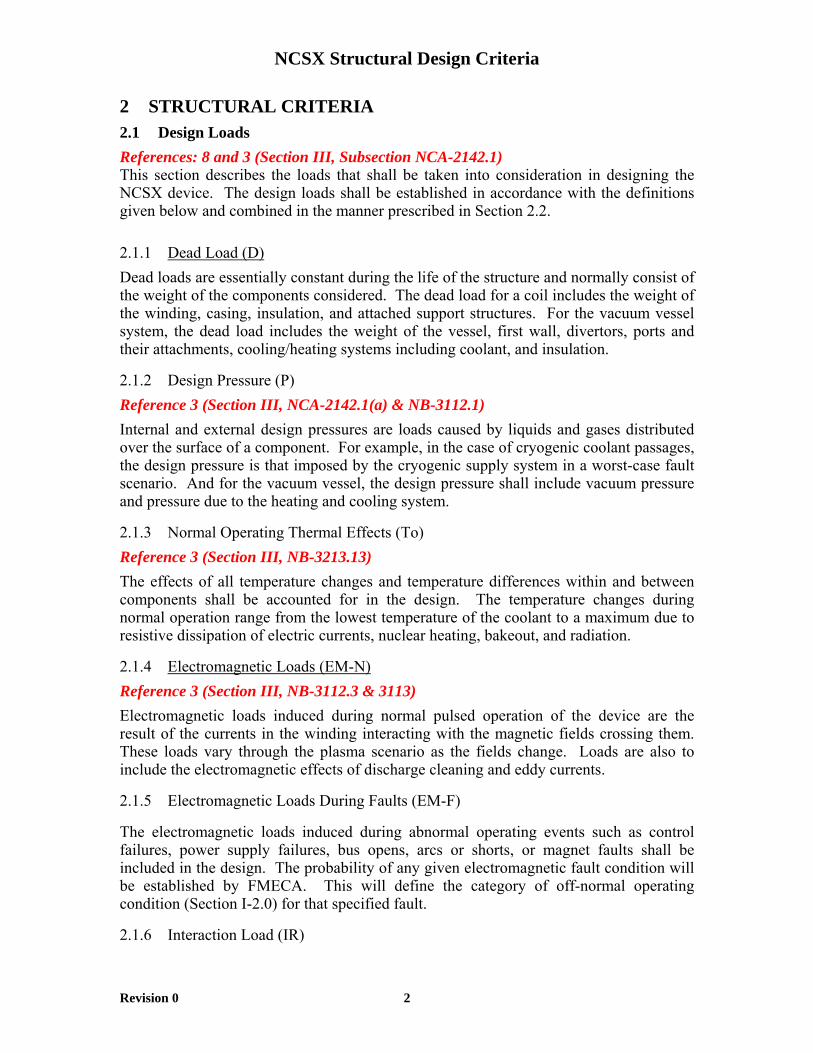
2 STRUCTURAL CRITERIA 2.1 Design Loads References: 8 and 3 (Section III, Subsection NCA-2142.1) This section describes the loads that shall be taken into consideration in designing the NCSX device. The design loads shall be established in accordance with the definitions given below and combined in the manner prescribed in Section 2.2. 2.1.1 Dead Load (D) Dead loads are essentially constant during the life of the structure and normally consist of the weight of the components considered. The dead load for a coil includes the weight of the winding, casing, insulation, and attached support structures. For the vacuum vessel system, the dead load includes the weight of the vessel, first wall, divertors, ports and their attachments, cooling/heating systems including coolant, and insulation.
2.1.2 Design Pressure (P) Reference 3 (Section III, NCA-2142.1(a) & NB-3112.1) Internal and external design pressures are loads caused by liquids and gases distributed over the surface of a component. For example, in the case of cryogenic coolant passages, the design pressure is that imposed by the cryogenic supply system in a worst-case fault scenario. And for the vacuum vessel, the design pressure shall include vacuum pressure and pressure due to the heating and cooling system.
2.1.3 Normal Operating Thermal Effects (To) Reference 3 (Section III, NB-3213.13) The effects of all temperature changes and temperature differences within and between components shall be accounted for in the design. The temperature changes during normal operation range from the lowest temperature of the coolant to a maximum due to resistive dissipation of electric currents, nuclear heating, bakeout, and radiation.
2.1.4 Electromagnetic Loads (EM-N) Reference 3 (Section III, NB-3112.3 & 3113) Electromagnetic loads induced during normal pulsed operation of the device are the result of the currents in the winding interacting with the magnetic fields crossing them. These loads vary through the plasma scenario as the fields change. Loads are also to include the electromagnetic effects of discharge cleaning and eddy currents.
2.1.5 Electromagnetic Loads During Faults (EM-F)
The electromagnetic loads induced during abnormal operating events such as control failures, power supply failures, bus opens, arcs or shorts, or magnet faults shall be included in the design. The probability of any given electromagnetic fault condition will be established by FMECA. This will define the category of off-normal operating condition (Section I-2.0) for that specified fault.
2.1.6 Interaction Load (IR)

NCSX Structural Design Criteria
Revision 0 3
Interaction loads include loads superimposed on the vessel, magnet or any other structure by the mutual interaction between themselves and other systems (for example, the loads imposed on the vacuum vessel by the plasma facing components).
2.1.7 Electromagnetic Loads Due to Plasma Disruption (EM-D)
Electromagnetic forces induced by plasma disruptions, including vertical displacement/disruption events (VDE), shall be considered in the design of any affected component of the NCSX device.
2.1.8 Seismic Loads (FDBE)
The NCSX facility will be classified as a Low Hazard (LC)/Hazard Category 3 (HC3) facility. All Structures, Systems, and Components (SSC) of NCSX shall be categorized in accordance with DOE-STD-1021-93 ("Natural Phenomena Hazards Performance Categorization Criteria for Structures, Systems, and Components," 7/93) to determine the appropriate Performance Category. For those SSCs that require seismic design, the applicable Design Basis Earthquake (DBE) acceleration values and evaluation techniques specified in DOE-STD-1020-94 ("Natural Phenomena Hazards Design and Evaluation Criteria for Department of Energy Facilities," 4/94) and DOE-STD-1024-92 ("Guidelines for Use of Probabilistic Seismic Hazard Curves at Department of Energy Sites," 12/92) shall be used.
2.1.9 Preloads (L)
These are loads applied during assembly of the machine, such as a pre-compression or tightening of bolts.
2.2 Load Combinations
The NCSX structural systems shall be designed for both normal operating conditions and off-normal events. The load combinations associated with each operating condition are defined in the following paragraphs where P represents the probability of occurrence per year [Reference 10]. The allowable stresses associated with each operating condition are specified in Section 2.4.
2.2.1 Normal Operating Events (Normal): P = 1
These are events that are planned to occur regularly in the course of facility operation. They are defined by the following terms:
D + P + TO + (EM-N) + IR + L
D + P + TO + (EM-D) + IR + L
2.2.2 Anticipated Events (Upset): 1> P ≥ 10-2
These are events of moderate frequency which may occur once or more in the lifetime of a facility. They are defined by the following terms:
NCSX Structural Design Criteria
Revision 0 4
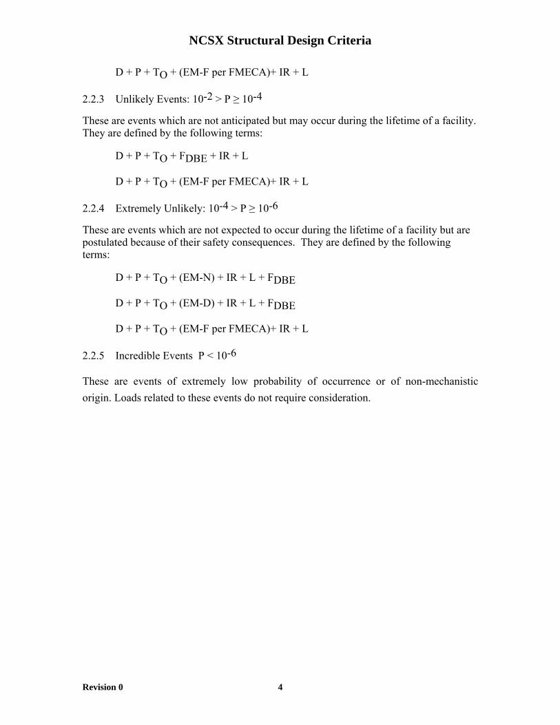
D + P + TO + (EM-F per FMECA)+ IR + L
2.2.3 Unlikely Events: 10-2 > P ≥ 10-4
These are events which are not anticipated but may occur during the lifetime of a facility. They are defined by the following terms:
D + P + TO + FDBE + IR + L
D + P + TO + (EM-F per FMECA)+ IR + L
2.2.4 Extremely Unlikely: 10-4 > P ≥ 10-6
These are events which are not expected to occur during the lifetime of a facility but are postulated because of their safety consequences. They are defined by the following terms:
D + P + TO + (EM-N) + IR + L + FDBE
D + P + TO + (EM-D) + IR + L + FDBE
D + P + TO + (EM-F per FMECA)+ IR + L
2.2.5 Incredible Events P < 10-6
These are events of extremely low probability of occurrence or of non-mechanistic origin. Loads related to these events do not require consideration.

NCSX Structural Design Criteria
Revision 0 5
2.2.6 Damage Limits and Recovery from Events Reference 9
Normal All the safety related structures, systems, and components are functional.
The component or support should maintain specified service function.
Within specified operational limit. Anticipated maintenance and minor adjustment.
Unlikely In addition to the challenged component, inspection may reveal localized large damage, which may call for repair of the affected components.
Material plasticity, local insulation failure or local melting which may necessitate the removal of the component from service for inspection or repair of damage to the component or support.
The facility may require major replacement of faulty component or repair work.
2.3 STRESS TERMINOLOGY
2.3.1 Stress Category Reference 3(Section III, NB-3213) 2.3.1.1 Primary Stress (PM, PL, PB)
Primary stress is a stress developed by the imposed loading which is necessary to satisfy the laws of equilibrium between external and internal forces and moments. The basic characteristic of a primary stress is that it is not self-limiting. In the absence of a clear definition, a stress shall be considered primary. There are three categories of primary stress:
• General Primary Membrane Stress (PM) - Reference 3 (Section III, NB-3213.6
Condition Functional And Damage Limit For The Experimental Facility
Damage Limits To Component Or Support
Recovery from Damage
Anticipated All the safety related structures, systems, and components are functional.
The component or support must withstand this loading without significant damage requiring repair.
Within specified operational limit. Anticipated maintenance and minor adjustment
Extremely Unlikely Gross damage to the affected system or component. Nevertheless the facility maintains the specified minimum safety function.
Gross general deformations, local melting and extensive insulation damage requiring repair, which may require removal of component from service.
Magnet system may be so damaged that repair is not considered economic.
NCSX Structural Design Criteria
Revision 0 6
• Local Primary Membrane Stress (PL) (e.g., a non-spherical head)
• Primary Bending Stress (PB) (e.g., a loaded beam) - Reference 3 (Section III, NB-3213.7)
An exception to this elastic analysis approach can be when the nature of the structure and its loading make it difficult to decompose the stresses into the above mentioned categories. In such an instance, a detailed, non-linear analysis that accounts for elastic-plastic behavior, frictional sliding and large displacement shall be used to determine the limit load on the structure [Reference 12]. The limit load is that load which represents the onset of a failure to satisfy the Normal operating condition as described in Section 2.2.6. The safety factor of limit load divided by the normal load shall be greater than 2.0.
2.3.1.2 Secondary Stress (Q) Reference 3 (Section III, NB-3213.9) Secondary stress is a stress developed by the constraint of the adjacent material or by the self-constraint of the structure. It must satisfy an imposed strain pattern rather than being in equilibrium with an external load. The basic characteristic of a secondary stress is that it is self-limiting within the ductility requirements specified in Section 2.4.1.2.
2.3.1.3 Peak Stress (F) Reference 3 (Section III, NB-3213.11) Peak stress is that increment of stress which is additive to the primary plus secondary stresses due to local discontinuity or local thermal stress, including the effects of stress concentrations. A peak stress does not cause any noticeable distortion but is a possible source of a fatigue crack or a fracture. Examples of peak stresses are:
• Surface stresses produced by thermal shock
• Stress concentration at local structural discontinuity
2.3.2 Definition of Tresca Stress (S) Reference 3 (Section III, NB-3213.1) Tresca stress is defined as twice the maximum shear stress and is equal to the largest algebraic difference between any two of the three principal stresses. This is equivalent to stress intensity as referred to in the ASME Boiler and Pressure Vessel Code [Reference 3].
2.3.3 Definition of Yield Stress (Sy) and Ultimate Tensile Strength (Su)
Yield stress (Sy) is the one-dimensional average stress at which a 0.2 % permanent strain offset is obtained at the design temperature. Ultimate tensile strength (Su) is the maximum tensile stress (based on the original area of the sample) that can be withstood before rupture at the design temperature.
Minimum specified yield and ultimate stress values for well-characterized materials shall be taken from established industry standards (such as ASME, AISC and/or MIL-HDBK-

NCSX Structural Design Criteria
Revision 0 7
5). If a small database exists for a candidate material considered for a design component, a statistically sound sampling shall be made of specimens taken from representative lots. Furthermore, these measurements shall be confirmed by testing the final production material to confirm compliance with initial design strengths.
2.4 METALLIC STRUCTURAL ACCEPTANCE CRITERIA
2.4.1 Monotonic Stress Limits
2.4.1.1 Design Tresca Stress Values (Sm)
• For conventional (i.e., non-superconducting, non-composite) conductor materials, the design Tresca stress values (Sm) shall be 2/3 of the specified minimum yield strength at temperature, for materials where sufficient ductility is demonstrated (see Section I-4.1.2). Reference 8 uses 1/2 Su for steel components ONLY, and a ductility requirement needs to be determined for any other metal. The reasoning is that 1/2 Su may be too limiting for ductile metals whose yield and ultimate are relatively close to each other. A requirement tied to elongation or reduction in area may be more appropriate than 1/2 Su for these metals.
• For support structures and any other STEEL structures including, if applicable, the vacuum vessel, the design Tresca stress values (Sm) shall be based on the lesser of the following:
o 2/3 of the minimum specified yield at temperature
Reference 3 (Section III, Appendix III, Article III-2110(a)(3))
o 1/2 of the minimum specified tensile strength at temperature
Original 1/3 Su per Ref. 3 (Section III, Appendix III, Article III-2110(a)(1)).
• For any other metallic structural component of NCSX that is neither conductor nor steel, the design Tresca stress values (Sm) shall be:
• 2/3 of the minimum specified yield at temperature
• Also, the component must meet ductility requirements which are to be established for each specific material.
Reference 8 uses 1/2 Su for steel components ONLY, and a ductility requirement needs to be determined for any other metal. The reasoning is that 1/2 Su may be too limiting for ductile metals whose yield and ultimate are relatively close to each other. A requirement tied to elongation or reduction in area may be more appropriate than 1/2 Su for these metals.

NCSX Structural Design Criteria
Revision 0 8
• For bolting materials, the design Tresca stress values shall be:
o 2/3 of the minimum specified yield strength at every point in time
Reference 3(Section III, Appendix III, Article III-2120) specifies 1/3
o Also, the component must meet ductility requirements which are to be established for each material not specified by Reference [3].
See Section 2.4.1.4.3 for bolting stress limits.
A weld is defined in this Criteria as the entire weld region, including the heat affected zone (HAZ) and the weld metal.
For any weld where the ASME Boiler and Pressure Vessel Code [Reference 3] does not apply (e.g., non-standard materials, geometries), the criteria and commentary below shall be used:
• For welds in steel, the design Tresca stress shall be the lesser of:
o 2/3 of the minimum specified yield if the weld at temperature, or
o 1/3 of the minimum specified tensile strength of the weld at temperature.
• For welds in materials other than steel, the design Tresca stress shall be:
o 2/3 of the minimum specified yield of the weld at temperature, and o Also, the weld must meet ductility requirements to be established for each
type of weld independently. Reference 8 uses 1/3 Su for welds in steel and an equivalent ductility
requirement for welds in metals other than steel. Since weld properties are very strongly a function of the weld metallurgy and technique, the yield and tensile strength shall be the minimum of the values resulting from a test lot of at least 6 specimens. The test specimens shall be standard tensile test specimens which are representative of a weld joint and in compliance with recognized testing procedures (such as the ASTM or ASME). For the test lot to be valid, welder qualification and weld technique must be developed until consistency (test results within +/- 15% of the average value) is achieved. Residual stresses shall be considered in design and analysis of welds.
• For a modular, non-superconducting conductor, refer to Section 2.6.

NCSX Structural Design Criteria
Revision 0 9
2.4.1.2 Material Ductility Requirements Ductility is a measure of the capacity of a material to inelastically (plastic) deform in tension or shear without rupture for its given environment. Terms commonly associated with the measurement of material ductility include elongation and reduction of area. Materials chosen for use in NCSX shall meet, at a minimum, ductility requirements which must be evaluated for each material independently if not specified by an established standard.
The acceptability of the ductility of a candidate material shall be determined from analysis of the component for which the material is specified. The degree of plasticity necessary to relieve secondary stresses in the component, and the required strain absorbing characteristics of the component under all design conditions defined in Section 2.2 shall determine the degree of plasticity required of the material. Elastic-Plastic limit analysis of the component may be necessary to quantify required plastic strain capacities for component materials. 2.4.1.3 Creep Creep is defined as a strain increase over time at constant stress and is observed at all service temperatures. The creep rate is a function of material, stress level, and temperature and must be accounted for in component design. Since NCSX will operate with an aperiodic operating cycle, the effects of creep must be determined experimentally and may require adjustment of the stress intensity to reduce creep effects. 2.4.1.4 Stress Allowable Limit Reference 3 (Section III, NB-3221/2) The Tresca stress resulting from the load combinations defined in Section2.2 shall not exceed the limits described in the following paragraphs: 2.4.1.4.1 Basic Stress Limits Based on elastic stress analyses, the following stress limits shall be met:
• General primary membrane stress shall not exceed 1.0 KSm
Reference 3 (Section III, NB-3221.1)
• Local primary membrane stress shall not exceed 1.5 KSm
Reference 3 (Section III, NB-3221.2)
• Primary membrane plus bending stresses shall not exceed 1.5 KSm
Reference 3 (Section III, NB-3221.3)
NCSX Structural Design Criteria
Revision 0 10
• Total primary plus secondary stress shall not exceed 3.0 KSm
Reference 3 (Section III, NB-3222.2)
• The multiplier K is dependent on the level of service conditions and listed in Section 2.4.1.5.
2.4.1.4.2 Special Stress Limits For geometries which involve bearing close to a free or protruding edge, a pin in a hole, shear keys and rings, bolted connections, screw threads and other complex stress conditions, a conservative hand calculation or a detailed finite element analysis shall be performed. The stress limits for these conditions shall be the same as those outlined in Section 2.4.1.4.1.
In the absence of a detailed finite element calculation, a conservative hand calculation may be performed for the following conditions, using the limits identified:
• The average bearing stress for resistance to crushing under the maximum design load shall be limited to the yield strength, Sy, at temperature. An exception occurs when the distance to a free edge is greater than the distance over which the bearing load is applied. In that case, a stress of 1.5 Sy at temperature is permitted.
• When bearing loads are applied on parts having free edges such as at protruding edges, the possibility of shear failure shall be considered. The average shear stress shall not exceed 0.6 KSm.
• When considering bearing stresses in pins and similar members, the Sy value at temperature is applicable, except that a value of 1.5 Sy may be used if no credit is given to bearing area within one pin diameter from a plate edge.
• The average primary shear stress across a section loaded under design conditions in pure shear (e.g., keys, shear rings, screw threads) shall be limited to 0.6 Sm. The maximum primary shear under design considerations, exclusive of stress concentration at the periphery of a solid circular section in torsion, shall be limited to 0.8 Sm.
2.4.1.4.3 Stress Limits for Bolting Material
For preload:
• Bolt preload stress shall not exceed the lesser of 0.75 Sy at room temperature or 0.75 Sy at operating temperature.
For operating loads:
• Average tensile stress due to primary loads shall not exceed 1.0 Sm.

NCSX Structural Design Criteria
Revision 0 11
• Maximum direct tension plus bending stress due to primary loads shall not exceed 1.5 Sm.
For preload combined with operation:
• At any point in time, combined operating loads and preload shall be evaluated for compatibility with joint design but in any case the maximum direct tension plus preload stress shall not exceed 0.9 Sy.
2.4.1.5 K Factors
The appropriate K values [Ref. 3, 8] for various load combination categories are:
• For normal operating conditions: K = 1.0
Ref. 3 (Section III, NB-3222)
Except that reduced K values shall be used for welds in thick plates (greater than 20 mm thick) for normal operating conditions. [Reference 9]:
o K = 0.9 for plates from 20 to 150 mm thick
o K = 0.8 for plates greater than 150 mm thick
• For anticipated conditions, K = 1.1 [Reference 3 (Section III, NB-3223)]
• For unlikely conditions, K = 1.2; evaluation of secondary stress not required [Refernce 3 (Section III, NB-3224)]
• For extremely unlikely conditions, K = 1.35; evaluation of secondary stress not required. [Reference 3 (Section III, NB-3226)]
Refer to Sections 2.2.1 to 2.2.5 for definitions of operating conditions. An alternative requirement would be to meet the operating conditions as defined in Section 2.2.6.
2.4.2 Fatigue Strength Evaluation
NCSX is designed for approximately 130000 full power pulses. A fatigue strength evaluation is required for those NCSX components with undetectable flaws that are either cycled over 10,000 times or are exposed to cyclic peak stresses exceeding yield stress. However, any NCSX component without cyclic tensile loading and loaded only in compression shall not require a fatigue evaluation. When a fatigue strength evaluation is performed, it shall apply both to base metal and the weld regions. It is essential that the quality and history of all materials used be known and documented prior to testing or fabrication.
2.4.2.1 ASME B&PV Code-Oriented Fatigue Evaluation Procedure

NCSX Structural Design Criteria
Revision 0 12
This section describes a traditional fatigue strength evaluation approach based on the ASME code. Stress intensity, as discussed within this section, refers to the Tresca stress defined in Section 2.3.2. For further clarification, a numerical example of this procedure can be found in the Commentary supplement to this Criteria document.
The cyclic loadings specified under the normal operating and upset service conditions shall be evaluated against fatigue failure. The total stress resulting from PM + PL + PB + Q + F (see Section 2.3.1) shall be used in the alternating stress intensity calculation.
2.4.2.1.1 Derivation of the Alternating Stress Intensity (Salt)
Reference 5 (Section III, NB-3216.1)
For each applicable service condition, the stress differences and the alternating stress intensity during the cyclic loading shall be calculated. When the principal stress direction does not change with time, stress difference is defined as the difference between any two of three principal stresses. Alternating stress intensity is equal to the largest of the amplitudes of the fluctuation of the three stress differences during the cycle.
2.4.2.1.2 Rotation of Principal Stresses Reference 5 (Section III, NB-3216.2) When the directions of the principal stresses change with time, the stress difference shall be calculated based on the six time-dependent stress components as outlined below:
• Consider the value of the six stress components (3 normal, 3 shear) as a function of time for the complete stress cycle, where the three normal stresses, e.g., Sx, Sy, and Sz are in an orthogonal coordinate system and the shear stresses are on the 45˚ planes to the orthogonal normal directions.
• Choose a point in time when the conditions are one of the extremes for the cycle, either a maximum or a minimum algebraically, and identify the stress components at this time by the subscript i. It may be necessary to try different points in time to find one which results in the largest value of alternating Tresca stress.
• Subtract each of the stress components at various time points from the subscript i components and denote the resulting components by a prime superscript
(e.g., S'z ).
• At each point in time, calculate the principal stresses based on these primed components (S1', S2' and S3').
• Determine the principal stress differences as a function of time (S12' = S1' - S2', S23' = S2' - S3' and S13' = S1' - S3'), and find the largest absolute magnitude of any stress difference at any time. The alternating Tresca stress is one-half of this magnitude.

NCSX Structural Design Criteria
Revision 0 13
2.4.2.1.3 Derivation of Mean Stress (Smean)
Reference 5 (Section III, NB-3222.4(c)) Mean stress is defined as the average value of the maximum stress and minimum stress in a stress cycle. Should the design fatigue curve not include the maximum effect of mean stress, the stress shall be modified as follows when the calculated maximum stress or alternating stress intensity is higher than the yield strength:
• If Smax > Sy and Salt < Sy then Smean = Sy - Salt
• If Salt > Sy then Smean = 0
where Smax = maximum stress
Smean = modified mean stress
Sy = yield strength
2.4.2.1.4 Calculation of Equivalent Alternating Stress Intensity (Seq)
When the design fatigue curve does not include the maximum effect of mean stress, an equivalent alternating stress intensity shall be calculated. The equivalent alternating stress intensity is to replace the alternating stress intensity before entering the fatigue curve, and is given by: Salt Seq = ___________ 1 - (Smean/Su) where Su = tensile strength 2.4.2.1.5 Calculation of Cumulative Usage Factor (U) Reference 5 (Section III, NB-3222.4(e)(5)) In many cases a point will be subjected to a variety of stress cycles during its lifetime. The cumulative effect of these various cycles shall be evaluated by means of a linear damage relationship in which it is assumed that: ni is the required number of cycles corresponding to the (Seq)i component. Based on the design S-N fatigue curve, which is discussed in Section 2.4.2.1.6, the Ni corresponding to (Seq)i can be determined. Ni is the number of cycles that would produce fatigue failure at a stress level of (Seq)i. The
cumulative usage factor, U, must be evaluated over the entire range of stress conditions, m, such that :

NCSX Structural Design Criteria
Revision 0 14
m U = Σ ni/Ni < 1.0 i
The cumulative usage factor shall be less than one, establishing the fatigue strength requirement. 2.4.2.1.6 Design Stress-N (S-N) Fatigue Curves Reference 8 The S-N fatigue curves shall be obtained based on uniaxial strain cycling tests at given temperatures (service temperatures) and at various R ratios (R = Smin / Smax). S-N fatigue curves shall be developed for both the base metal and for weld regions.
The design S-N fatigue curve shall be obtained by applying a factor of 2 on stress or a factor of 20 on cycles, whichever is more conservative, to the best fit curve to the data. A minimum of three test samples is required for every stress level and R ratio used to develop an S-N curve. If the scatter is deemed significant, additional samples would be required.
The 2/20 approach is an accepted aerospace practice adopted by the U.S. fusion community.
2.4.2.2 Crack Growth Limitation Reference 5, Section III, Appendix G Crack growth analyses based on linear elastic fracture mechanics (LEFM) shall be performed in the design where the combination of geometry, stresses, materials and detected flaws indicate a potential for crack propagation. Using design stress allowables (or the fatigue stress allowables derived in Section 2.4.2.1, if a fatigue analysis was performed), LEFM analyses shall be used to quantify the permissible initial flaw size for both the base metal and the weld regions. The maximum permissible initial flaw size shall be governed by, as a minimum, two times the growth life experimentally determined based on component tests, or four times the growth life experimentally determined based on material tests. A minimum of 3 sample components or 6 material samples shall be used in the experimental determination. Certain materials or orientations may require additional specimens over and above these criteria, if the scatter of the data is deemed significant. Note that in the evaluation of flaw propagation, the definition of failure criteria may vary and needs to be specified by the designer. For example, a member may develop a through-flaw which may not jeopardize the structural integrity of the member itself, but may constitute the failure of a system if the member is part of a vacuum or pressurized boundary that is violated due to the flaw.
2.4.2.2.1 Stress Analysis

NCSX Structural Design Criteria
Revision 0 15
Fatigue crack growth (stage 2) is controlled primarily by maximum principal stresses (or strains). Fatigue cracks will usually propagate in the direction normal to a uniaxially applied load and the rate and direction of crack growth can be affected by loads and restraints in other directions as well as environmental conditions.
Note that a compressive T-stress (a stress which is independent of the distance from the crack tip and parallel to the crack surface), with the principal stress near or exceeding yield, increases the crack tip opening displacement and hence, probably the crack growth rate above that predicted by linear elastic fracture mechanics. This is equivalent to a biaxial condition where the Poisson effect of a compressive stress in the secondary direction increases the stress intensity at the crack tip. A nominal stress greater than 2/3 yield produces a larger plastic zone at the crack tip and a faster crack growth rate than predicted by LEFM. Failure may occur as the limit load drops to Pmax before the critical crack length as predicted by LEFM is reached.
Finite element analysis can be used to ascertain potential crack initiation points in a design, as well as predict the direction of crack propagation for complex load scenarios that would be otherwise impossible to determine by test.
The rainflow (or alternate) method shall be used to resolve the aperiodic cyclic history into several equivalent constant amplitude fatigue blocks or cycles.
2.4.2.2.2 Material Inspection Requirement For inspection, a back calculated initial flaw size, based on a failure scenario, cannot be smaller than twice the minimum flaw that can be resolved by nondestructive testing of the same material in a comparable geometry. The inspection procedure and results shall be included in the design documentation, along with the description of any calibration fixtures used.
2.4.2.2.3 Mean Stress Effect
Some materials, including high strength alloys and solders, have demonstrated crack growth rates which are more sensitive to the stress intensity range (∆K) than others. In some cases, the growth rates are quite sensitive to the mean stress level, where ∆K is constant.
An established LEFM methodology shall be used to account for the mean stress effect on crack growth rates, where deemed appropriate. The effects of closure and interaction for applicable load scenarios and values of R shall be considered.
It is not appropriate to specify one crack growth rate equation as a standard. Due to the variables that are encountered, including but not limited to material, temperature, stress ratio, and geometry, the designer must consider from these crack growth options, within the context of available test data, and choose the empirical equation that best fits each situation.

NCSX Structural Design Criteria
Revision 0 16
2.4.2.2.4 Calculation of Cumulative Usage Factor (U)
The damage accumulation shall be evaluated by the same approaches described in Section 2.4.2.1.5.
2.4.2.2.5 Design S–N Fatigue Curves for Crack Growth
The crack growth curves shall be obtained based on constant stress tests for both the base metal and weld regions. The crack growth life shall be estimated by a suitable method.
2.4.2.2.6 Determination of Fracture and Crack Growth Rate Constants
Fracture and crack growth constants can be very sensitive to many variables and circumstances can arise where the material constants for fracture and crack growth rate are not known for a given material, loading, temperature or environmental condition. In the absence of reliable data, these constants must be determined experimentally. The determination of plane strain fracture toughness, KIC, shall conform with ASTM standard E399 or E813, whichever is deemed more appropriate. Although the critical stress intensity for plane stress conditions is higher than that for plane strain, to be conservative plane strain conditions will be assumed for all sections thicker than 10 mm. If the aspect ratio in the other two dimensions is less than ten-to-one with respect to thickness, then plane strain conditions will be assumed for thicknesses less than 10 mm as well.
The calibration of crack growth rates shall conform with ASTM standard E647. These ASTM standards not only discuss test procedures but also outline appropriate specimen configurations and number of specimens constituting a valid test sample. Note that short cracks can grow faster than what is predicted by long crack data. When a wide temperature range encompasses the performance criteria, such as R.T. to 4K, it will be necessary to establish material constants at intermediate temperature values in order to determine the function and sensitivity of the constants with temperature.
2.4.3 Metallic Structural Stability
Reference 8
2.4.3.1 General Requirements
Design loads on all relevant structures shall be derived from a structural model which includes the effects of redundancy, load share, thermal constraint and possible buckling of secondary elements. The buckling load shall be determined by either of the following approaches:
• By the linear bifurcation analyses reduced by capacity reduction factors which account for the effects of geometrical imperfections and by plasticity reduction factors which account for nonlinearity in material properties. Capacity reduction (or "knock-down") factors shall be chosen consistent with published industry practice.
NCSX Structural Design Criteria
Revision 0 17
• By nonlinear plastic analysis including the effects of geometrical imperfections, material nonlinearities, and large deformation.
The approach shall be selected consistent with the type of buckling predicted by the structure's geometry and constraints.
For dynamic loadings, the dynamic amplification shall be considered in the buckling evaluation unless a rigorous dynamic instability analysis is performed.
Thermal-induced compressive stresses shall be considered to be additive to stresses due to other concurrent loads.
2.4.3.2 Factor of Safety
For an elastic buckling analysis (with ‘infinitesimal’ imperfection), a minimum factor of safety (FS) of 5.0 is required between the critical buckling load determined by the requirements of Section 2.4.3.1 and the applied loads. For elastic and inelastic (non-linear) buckling evaluations that consider geometrical imperfections, large displacement and/or plastic collapse, a minimum FS of 2.0 against collapse shall be used. For short columns where buckling instabilities are not credible (it can be demonstrated that the yield of the column will occur before buckling), Section 2.4.1 shall apply.
2.5 NON-METALLIC STRUCTURAL ACCEPTANCE CRITERIA
Mechanical failure of the insulation is assumed to eventually result in electrical breakdown and/or structural failure in coils due to load re-distribution resulting from reduction in overall coil stiffness.
2.5.1 Scope
This section describes the design criteria for nonmetallic materials. These materials include electrical and thermal insulation systems, low-friction sliding polymers, and shim composites or polymers. The electrical insulation systems include turn-to-turn, layer-to-layer, and ground electrical insulation within and between magnets. The criteria refer to materials with a 2-dimensional reinforcing (in the warp and weft directions).
2.5.2 Design Criteria
2.5.2.1 Mechanical Limits for Insulation Materials
The stress criteria defined herein may be locally exceeded by secondary stresses in an area whose characteristic length along the insulation plane is not more than the insulation thickness and where it can be demonstrated that cracking or surface debonding parallel to the insulation layer and limited to the local length will relieve the stresses without violating the integrity of the structure. In this situation, final verification must be obtained by mechanical/electrical testing of a representative winding pack section.

NCSX Structural Design Criteria
Revision 0 18
2.5.1.1.1 Compressive Stress Allowable
• Static - The design allowable flatwise (through-thickness) compressive stress of continuous sheets of insulating material shall be limited to 2/3 of the ultimate stress at temperature. [NOTE: Reference 13 suggested a more conservative value of 1/2 ultimate stress]
• Fatigue
The compressive stress fatigue allowable shall be equal to the lesser of:
o 2/3 of the ultimate compressive fatigue stress at temperature measured at the lifetime number of cycles [NOTE: Reference 13 suggests a more conservative value of 1/2 ultimate stress]
o The ultimate compressive fatigue stress at temperature at 5x the lifetime cycles, or when shear is present, the worst case combination of compression and shear using a representative test specimen configuration as discussed in Section I-5.2.1.3 [NOTE: Reference 13 suggests a more conservative 10x on cycles]
2.5.1.1.2 Tensile Strain Allowable Normal to Plane
In the direction normal to the adhesive bonds between metal and composite, no primary tensile strain is allowed. Secondary strain will be limited to 1/5 of the ultimate tensile strain. In the absence of specific data, the allowable working tensile strain is 0.02% in the insulation adjacent to the bond.
2.5.1.1.3 Shear Stress Allowable
The shear-stress allowable, Ss, for an insulating material is most strongly a function of the particular material and processing method chosen, the loading conditions, the temperature, and the radiation exposure level. The shear strength of insulating materials depends strongly on the applied compressive stress. Therefore, the following conditions must be met for either static or fatigue conditions:
Ss = [2/3 τo]+ [c2 x Sc(n)]
[NOTE: Reference 13 suggests 1/2 for static and fatigue loading when capacities have been measured and 1/3 for fatigue when fatigue data is lacking.]
Where:
τo = the experimentally determined minimum intrinsic shear strength of the material with no compressive load at the temperature and radiation dose representative of the service condition. The strength will represent the lower of the bond shear strength or the composite interlaminar shear strength. This value is to be the minimum value from a sample lot of at
NCSX Structural Design Criteria
Revision 0 19
least 6. For the sample lot to be valid, the process is to be developed such that the scatter of values shall not exceed +/- 10% from the mean value.
c2 = an experimentally determined factor for the proposed insulating material based on combined shear and compression testing at the temperature and radiation dose level representative of the service conditions. The constant represents the slope of the dependence of shear strength on compressive stress.
Sc(n) = the applied normal compressive stress
The shear allowable must, in all cases, be verified by testing of irradiated test specimens of the materials selected subjected to a calibrated or equivalent in situ exposure. Adequate fatigue life must be demonstrated for five times the design life with combined shear and compression loading using representative samples. In cases where slippage is expected to occur, laboratory tests of the suitability of the wear characteristics of the chosen materials for at least five times the design life must be made, using representative test specimen configuration(s).
2.5.1.1.4 In-Plane Strain Allowable
The in-plane strains are usually secondary stresses, imposed by the coil structural material. In the absence of measured strain absorbing data for an insulation material, the maximum tensile or compressive strain permitted in the plane of the insulation material is either +0.5% or -0.5%. This strain limitation is imposed to preclude micro cracking in the through-thickness direction of the insulation sheets. The strain limits normal to the plane of the insulation are considered to be independent of the in-plane strain.
2.5.1.2 Coefficient of Friction
The allowable coefficient of friction (a) must always be determined in a conservative manner. Unlike stress, in some cases it is conservative to permit a coefficient of friction higher than the average measured value and, in some cases, lower than the measured value. The guidelines are:
amin = a - 0.15 but ≥ 0.02
amax = a +0.15
Friction values outside the range 0.1-0.4 require exceptional justification. The case of friction coefficient extremes must be considered as anticipated upset conditions in the design.
2.5.1.3 Radiation Limits
The allowable radiation limits on the insulation have two components, both of which must be satisfied:

NCSX Structural Design Criteria
Revision 0 20
• The peak dose arising from gamma radiation on organic insulation in any of the coils is 1 x 10⁹ rads (10MGy). This includes the local gamma dose arising from neutrons.
• The peak fast neutron fluence (<0.1 MeV) is 5x10²¹ n/m2
These values are the maximum local values actually experienced, and so do not include safety factors for nuclear radiation calculations.
2.6 NON-SUPERCONDUCTING MODULAR COIL CONDUCTOR STRUCTURAL ACCEPTANCE CRITERIA
2.6.1 Scope
This section describes the design criteria for NCSX non-superconducting modular coils. Since a modular coil is comprised of stranded and braided conductor cable embedded in a vacuum impregnated insulation matrix, a coil will not respond to mechanical loads in the same way as a standard homogeneous metallic component (Section 2.4) or non-metallic component (Section 2.5). This necessitates separate criteria to address the various potential failure modes and limits of the coil. Failure is defined as the state in which the coil has lost either its mechanical or electrical integrity. The behavior of modular coil bundles will likely be dictated by the insulation layers that separate each individual coil. Accordingly, refer to Sect. 2.5 to determine the limits of turn-to-turn insulation in the bundle.
2.6.2 Design Criteria
2.6.2.1 Initial Quantification of Applied Stress
Bounding calculations shall be used to provide an initial estimate of the load sharing and acceptability of stresses (and/or strains) in the copper and epoxy/glass.
In a modular coil design, such as is used in NCSX, the load sharing between the cable, insulation and casting shall be initially evaluated in the following manner in the absence of definitive test data:
• Perform a structural (finite element) analysis, assuming a minimum anticipated modulus for the potted conductor cable and insulation (suggested minimum modulus is 5 percent of copper). This assumption would represent an un-impregnated section of cable. In this case, the load will primarily be transferred to and carried by the structure. This results in the maximum winding pack strain and structure stress. Strain compatibility between the conductor and structure can be used to determine the upper limit of the winding pack strain.
• Repeat, using the anticipated maximum modulus of the potted cable, but in no case greater than 75 percent of the copper modulus. This would reflect the situation where the cable is fully impregnated; its higher modulus would result in the maximum load carried by the conductor. Structural analysis, based on this upper modulus bound, shall be used to guide any material and/or component test program by indicating locations and magnitudes of dominant stress.
NCSX Structural Design Criteria
Revision 0 21
2.6.2.2 Final Qualification of Applied Stress Determine the actual tension and compression moduli bounds, based on mechanical testing with a sampling size that is statistically representative. The bounds are still necessary because of the anticipated scatter in results even with numerous samples.
2.6.2.3 Mechanical Limits for a Modular Coil
2.6.2.3.1 Axial Compressive Stress Allowable
• Static - Failure is defined as the state in which the coil has lost either its mechanical or electrical integrity. Once testing has determined the probable failure mode(s), the design allowable axial compressive stress shall be limited 2/3 of the minimum failure stress at temperature .
• Fatigue - The design S-N fatigue curve representing the axial compressive stress fatigue allowable shall be equal to the lesser of:
o 1.5X of the design axial compressive fatigue stress at temperature measured at the lifetime number of cycles or
o The design axial compressive fatigue stress at temperature at 5x the lifetime cycles.
In the absence of an adequate design S-N fatigue curve, it will be necessary to demonstrate by component testing that the fatigue limits of 1.5X the design stress at temperature and cycles as well as 5X cycles at temperature and design stress can be met.
2.6.2.3.2 Transverse Compressive Stress Allowable
• Static - Failure is defined as the state in which the coil has lost either its mechanical or electrical integrity. Once testing has determined the probable failure mode(s), the design allowable transverse compressive stress shall be limited 2/3 of the minimum failure stress at temperature
• Fatigue - The design S-N fatigue curve representing the transverse compressive stress fatigue allowable shall be equal to the lesser of:
o 1.5X of the design transverse compressive fatigue stress at temperature measured at the lifetime number of cycles or
o The design transverse compressive fatigue stress at temperature at 5x the lifetime cycles.
In the absence of an adequate design S-N fatigue curve, it will be necessary to demonstrate by component testing that the fatigue limits of 1.5X the design stress at temperature and cycles as well as 5X cycles at temperature and design stress can be met.
2.6.2.3.3 Axial Tension Stress Allowable
NCSX Structural Design Criteria
Revision 0 22
• Static - If the yield stress can be defined by testing, the design allowable tension stress shall be limited to the lesser of the following:
o 2/3 of the minimum yield stress at temperature or
o 1/2 of the minimum ultimate stress at temperature.
In the absence of a well-defined yield stress, the design allowable tension stress shall be limited to 1/2 of the minimum failure stress at temperature while maintaining a ductility requirement as outlined in Section 2.4.1.2. Failure is defined as the state in which the coil has lost either its mechanical or electrical integrity.
• Fatigue - The tension stress fatigue allowable for a single modular coil conductor shall be in conformance with the criteria defined in Sect. I-4.2. In the absence of an adequate design S-N fatigue curve, it will be necessary to demonstrate by component testing that the fatigue limits of 2X the design stress at temperature and cycles as well as 20X cycles at temperature and design stress can be met.
2.6.2.3.4 Axial Tensile Strain Allowable
In addition to a tensile stress limit, a single modular coil conductor shall have a strain limit of 1/2 of the ultimate tensile strain at temperature based on testing. This limit may be reduced further if performance requirements of the conductor warrant it.
2.6.2.3.5 Flexure Stress Allowable
• Static - If the flexure yield stress can be defined by testing, the design allowable flexure stress shall be limited to the lesser of the following:
o 2/3 of the minimum yield stress at temperature or
o 1/2 of the minimum ultimate stress at temperature.
In the absence of a well-defined flexure yield stress, the design allowable flexure stress shall be limited to 1/2 of the minimum failure stress at temperature while maintaining a ductility requirement as outlined in Section 2.4.1.2. Failure is defined as the state in which the coil has lost either its mechanical or electrical integrity.
• Fatigue - The tension stress fatigue allowable for a single modular coil conductor shall be in conformance with the criteria defined in Section 2.4.2. In the absence of an adequate design S-N fatigue curve, it will be necessary to demonstrate by component testing that the fatigue limits of 2X the design stress at temperature and cycles as well as 20X cycles at temperature and design stress can be met.
2.6.2.3.6 Shear Stress Allowable
In a modular coil, the shear stress limits will be defined by the adhesive and cohesive strengths of the epoxy as it bonds the cable, the glass and the glass to the cable matrix. Accordingly, refer to Section 2.5.1.1.3 to determine the shear stress allowables of the modular coil.

NCSX Structural Design Criteria
Revision 0 23
2.7 CRITICAL DESIGN ISSUES
Operational experience [Reference 11] has shown that failures are most likely to occur at points of discontinuity, such as at joints (bolted, soldered, brazed, or welded), at electrical lead terminations, and at coolant connections. These problems often occur because they are overlooked, since they are considered "design details" which are often deferred until late in the design process and often not included in critical design reviews, at least not at all stages. In an attempt to avoid these problems, the NCSX Project requires that these details be defined and engineered at a level consistent with the overall design and be presented at each critical design review stage of the project.
3 CRYOGENIC DESIGN CRITERIA
This section will appear in a future edition of this document.
4 HIGH HEAT FLUX AND HIGH TEMPERATURE COMPONENTS DESIGN CRITERIA
This section will appear in a future edition of this document.
5 VACUUM VIEWPORTS/VIEWING WINDOWS DESIGN CRITERIA
This section will appear in a future edition of this document.
6 DEVIATIONS FROM CRITERIA
Criteria for stellarators are, by their very nature, highly developmental in nature and may at times result in technical impasses. In instances where the criteria stated in this document cannot be met, approval by additional analysis may be sought. Such deviations shall only be made in exceptional cases and require sign-off by the Project Engineer, Cognizant Engineering Manager, and Work Package Manager.
In such cases, in-depth analyses, additional tests, and/or advanced analysis methods shall be made and formally submitted for consideration and approval. The process may involve expert peer reviews to resolve differences.
7 REFERENCES FOR CRITERIA
1. BPX, "BPX Magnet Structural Design Criteria", Report F-910208-PPL-03, Rev. 0, February 1991.
2. CIT, "CIT Vacuum Vessel Structural Design Criteria", Report D-890712-PPL-03 TR-03, Rev. R0, July 1989.
3. ASME, "1992 ASME Boiler and Pressure Vessel Code", July 1992.
4. AISC, "AISC Manual of Steel Construction", 1980.
5. ITER Documentation Series No. 26: "Iter Magnets"; International Atomic Energy Agency; Vienna; 1991.

NCSX Structural Design Criteria
Revision 0 24
6. J. W. Ekin, “Strain scaling law for flux pinning in practical superconductors. Part 1: Basic relationship and application to Nb3Sn conductors,” Cryogenics, V. 20(11), p. 611, Nov.. 1980.
7. M. Soell, "Influence of radiation damage on the maximum attainable magnetic field for a tokamak reactor,” J. Nuc. Matls 72 (1978), 168.
8. TPX, "TPX Structural and Cryogenic Design Criteria", Report 94-950606-PPPL-IZatz-02, TPX-STND-001, Rev. 1, June 1995.
9. ITER - Superconducting Coils and Structures Division, "Appendix C - Design Criteria", Report N11 RI 01 94-06-30 W2, June 1995.
10. Brynda, W.J., et. al., "Nonreactor Nuclear Facilities: Standards and Criteria Guide", Brookhaven National Lab. Doc. BNL-51444-Rev. 1, September 1986.
11. "Historical Database on Magnet System Failure Initiators", Final Report March 31 1995, Submitted to Wright Laboratory, US Air Force WRDC/21/P00X-3, Dayton, Ohio 45333 and Northeast Consortium for Engineering Education, 1101 Massachusetts Ave., S. Cloud FL 34769, for task NCEE/2419/Task 9 by MIT Plasma Science and Fusion Center.
12. ITER – “ITER Structural Design Criteria, In-Vessel Components”, Appendix B – Section B 2510, Report S 74 MA 1 97-12-12 R 0.2, December 1997.
13. ITER – “ITER Structural Design Criteria for Magnet Components (SDC-MC), Report N 11 FDR 50 01-07-05 R 0.1.

NCSX Structural Design Criteria
Revision 0 App A-1
APPENDIX A
COMMENTARY ON THE STRUCTURAL CRITERIA (SECTION I)
INTRODUCTION:
This Appendix, originally issued in memo PPPL-EAD-4436, dated February 22, 1993, serves as a supplement to the NCSX Criteria - Section 2 - Structural Criteria. It is intended to offer further clarification, interpretation, and commentary on its contents. Selected topics were chosen where questions have arisen and where some additional text would enhance and stress the intention of the Criteria. Numerical examples have also been added to illustrate the specific application of the Criteria. As NCSX progresses, additional commentary may be added on an as needed basis.
NUMERICAL EXAMPLE OF CALCULATING AVERAGE AND PEAK STRESSES
Assume a finite element model of a coil case comprised of six solid elements in its cross-section. The analysis shows the following results:
Elem# Area(in2) Sr Sθ Sz τrθ τθz τrz
1 10 0 -15 10 0 6 0
2 5 3 -20 15 0 5 2
3 5 3 -20 15 0 5 2
4 5 3 -25 20 0 4 2
5 5 3 -25 20 0 4 2
6 10 0 -30 25 0 2 0
Note: Stresses are in KSI at the element centroids.
• Compute the average stress for each of the six components:
Sravg = 4 x (3 x 5)/40 = 1.5 KSI
Sθavg = [- 15(10)-2(5)(20)-2(5)(25)-10(30)]/40 = - 22.5 KSI etc.
• Determine the three principal stresses from the three roots of:
σ3-(Sr+Sθ+Sz) σ2+(SrSθ+SθSz+SzSr-τrθ2-τθz2-τzr2) σ - (Sr Sθ Sz + 2τrθτθzτzr - Srτθz2 - Sθτzr2 - Szτrθ2) = 0
In this example the roots are;

NCSX Structural Design Criteria
Revision 0 App A-2
S1 = 18.2 KSI
S2 = 1.3 KSI
S3 = - 23.0 KSI
• Determine the largest algebraic difference between any two of the three principal stresses, i.e., (S1-S2), (S2-S3), (S3-S1). In this example the maximum difference equals S1-S3 = 41.2 KSI.
• Compare to the allowable membrane stress.
For peak stresses, the computational approach is identical except that instead of using average section stresses, use the peak stress found in the cross section, which in this case would be a value extrapolated to the edge of the most highly stressed element. In this example, the six element components extrapolated to the edge are:
Sr = 0. KSI Sθ = - 32.0 KSI Sz = 27.5 KSI
τrθ = 0. KSI τθz = 1.75 KSI τzr = 0. KSI
which leads to:
S1 = 27.6 KSI
S2 = 0. KSI
S3 = - 32.0 KSI
with (S1-S3) = 59.6 KSI, the peak stress, which is then compared to the allowable membrane plus bending stress.
SECTION 2.4.2.1 - ASME B&PV CODE-ORIENTED FATIGUE EVALUATION PROCEDURE
The following commentary and interpretation and numerical example is offered pertaining to the NCSX Design Criteria Document's discussion of the ASME B&PV Code-Oriented Fatigue Evaluation Procedure. For the general case where the directions of the principal stresses vary with time, it is necessary to determine the maximum algebraic difference of principal stresses during a cycle of loading by the following procedure:
• At various time points during the load cycle, establish the six components of stress, including the effects of any local stress concentration.

NCSX Structural Design Criteria
Revision 0 App A-3
• Through trial and error, determine a set of minimum or maximum stresses and subtract them from every other set of stresses at the various time points and label each set.
• For each time point, calculate the principal stresses for each labeled set, then determine the principal stress differences as a function of time and identify the largest absolute magnitude of these differences.
• The alternating stress intensity is equal to half of this magnitude and is then referred to the design S-N curve. This value of alternating stress intensity may need to be adjusted to account for the effect of mean stress (per Section 2.4.2.1.3 of the criteria document), if the design S-N curve does not account for it, which refers to the possibility that the uniaxial strain controlled fatigue tests used to develop the design S-N curve might not account for the appropriate values of stress ratio, R.
Two numerical examples follow. The first demonstrates the methodology involved when the orientation of the axes of principal stress vary between the two selected time points per the discussion in Section 2.4.2.1.2 of the criteria document on Rotation of Principal Stress. The second example illustrates the procedure when the orientation of principal stresses do not change between selected time points.
• Principal stresses change orientation between time point A, a maximum, and time point B, a minimum. Points A and B were selected from several time points during a cycle. Values depicted reflect basic stresses plus any stress concentration effects.
Stress Component @ Time Point A (KSI) @ Time Point B (KSI)
Sr 5.0 0
Sθ -25.0 -3.0
Sz 50.0 -6.0
τrθ 3.0 0
τθz 5.0 0
τzr 2.0 0
Take the difference of the six stress components between Time points A and B:
Sr' = 5.0 KSI τrθ' = 3.0 KSI
Sθ' = -22.0 KSI τθz' = 5.0 KSI

NCSX Structural Design Criteria
Revision 0 App A-4
Sz = 56.0 KSI τzr' = 2.0 KSI
Solving for principal stresses:
S1' = 56.4 KSI
S2' = 5.2 KSI
S3' = -22.6 KSI
The maximum difference between principal stresses is: (S1' - S3') = 79 KSI
Therefore the alternating stress amplitude is 79/2 = 39.5 KSI.
Note that for this calculation, the stress ratio, R = -22.6/56.4 = -0.4. This means that the design S-N curve, in order to be consistent with this calculation, should be able to predict failure for a stress ratio of -0.4 at an alternating stress level of 39.5 KSI.
• Principal stresses do not change orientation between time point A, a maximum, and time point B, a minimum.
Stress Component @ Time Point A (KSI) @ Time Point B (KSI)
Sr 3.0 3.0
Sθ -20.0 -2.0
Sz 40.0 5.0
τrθ 0 0
τθz 0 0
τzr 0 0
Stress Differnce @ Time Point A (KSI) @ Time Point B (KSI)
Sr- Sθ 5.0 0
Sz - Sθ -25.0 -3.0
Sz - Sr 50.0 -6.0
The maximum stress difference is 60-7 = 53 KSI.
Therefore the alternating stress amplitude = 26.5 KSI and a stress ratio R = (7/60) = + 0.12.

NCSX Structural Design Criteria
Revision 0 App A-5
SECTION 2.4.2.2 - CRACK GROWTH LIMITATION
The following commentary and interpretation and numerical example is offered pertaining to the NCSX Design Criteria Document's discussion of Crack Growth Limitations:
• A maximum permissible initial flaw in any component, for a given specified load and environmental condition, shall be determined either analytically, in which case the initial flaw size would be backcalculated assuming four (4) times the number of design life cycles, or experimentally, based on appropriate component testing, where the initial flaw size would be based on twice the number of cycles to failure of the test article.
• Once the initial flaw is determined, it must be ascertained whether it can be detected by non-destructive testing (NDT) in the proposed structure. Per Section 2.4.2.2.2, the initial flaw should be at least twice the size of the minimum flaw that can be detected by NDT of that material in a comparable geometry.
• Base metal and welds will each have their own fracture constants and must, therefore, be studies independently.
• To perform a fracture analysis, certain material constants are required. If these constants (Fracture toughness and Paris constants) exist in the literature for the proposed structural conditions, then they do NOT have to be determined experimentally. However, per Section 2.4.2.2.6, if these constants are not available, then they should be determined experimentally by the appropriate ASTM tests.
• If the fracture criteria are met, a structure must still meet both the static and fatigue criteria that are outlined elsewhere in the document.
As an example, assume a NCSX part must withstand 10000 cycles of service. It is made of a material for which the fracture constants are available, therefore NO material testing is required. For the given stress and temperature conditions, an initial flaw size of 10 mils is analytically determined to correspond to 40000 cycles of life (4x life based on material test). In turn, this requires NDT testing to be able to consistently resolve flaws of 5 mils for the part's design to be acceptable per the fracture criteria.
Using a numerical example to illustrate this situation, assume that the NCSX TF-coil case is made of 316 LN stainless steel and is cycled at a temperature of 76° K. The following fracture properties for 316 LN (R≈0) are well documented:
C = 1.49 x 10⁻⁹ in/cycle
n = 2.24
K IC = 242 ksi in
Assume that the initial flaw is a through edge crack and that the case wall being analyzed is 20 inches wide and can be assumed to be semi-infinite with the load applied remote to
NCSX Structural Design Criteria
Revision 0 App A-6
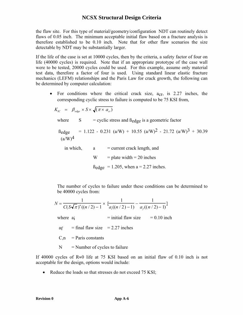
the flaw site. For this type of material/geometry/configuration NDT can routinely detect flaws of 0.05 inch. The minimum acceptable initial flaw based on a fracture analysis is therefore established to be 0.10 inch. Note that for other flaw scenarios the size detectable by NDT may be substantially larger.
If the life of the case is set at 10000 cycles, then by the criteria, a safety factor of four on life (40000 cycles) is required. Note that if an appropriate prototype of the case wall were to be tested, 20000 cycles could be used. For this example, assume only material test data, therefore a factor of four is used. Using standard linear elastic fracture mechanics (LEFM) relationships and the Paris Law for crack growth, the following can be determined by computer calculation:
• For conditions where the critical crack size, acr, is 2.27 inches, the corresponding cyclic stress to failure is computed to be 75 KSI from,
KIC = βedge × S × (π × acr)
where S = cyclic stress and ßedge is a geometric factor
ßedge = 1.122 - 0.231 (a/W) + 10.55 (a/W)2 - 21.72 (a/W)3 + 30.39 (a/W)4
in which, a = current crack length, and
W = plate width = 20 inches
ßedge = 1.205, when a = 2.27 inches.
The number of cycles to failure under these conditions can be determined to be 40000 cycles from:
N =1
C(S π )n ((n / 2) − 1× [
1ai((n / 2) −1)
−1
af ((n / 2) − 1)]
where ai = initial flaw size = 0.10 inch
af = final flaw size = 2.27 inches
C,n = Paris constants
N = Number of cycles to failure
If 40000 cycles of R≈0 life at 75 KSI based on an initial flaw of 0.10 inch is not acceptable for the design, options would include:
• Reduce the loads so that stresses do not exceed 75 KSI;

NCSX Structural Design Criteria
Revision 0 App A-7
• Reduce the number of cycles required so that a higher operating stress could be permitted;
• Find a more crack resistant material;
• Do a prototype test to permit a reduction in the safety factor required for the analysis;
• Alter the case design/geometry.
APPENDICES B, C, D, AND E WILL APPEAR IN FUTURE EDITIONS OF THIS DOCUMENT


![On revision of Deming Prize Evaluation Criteria - … · ON REVISION OF DEMING PRIZE EVALUATION CRITERIA 2 The Deming Prize:Evaluation Criteria [FY2018~(Proposed)] A. Establishment](https://img.dokumen.tips/doc/110x75/5ba0baab09d3f2497e8bc150/on-revision-of-deming-prize-evaluation-criteria-on-revision-of-deming-prize.jpg)