Embed Size (px)
Citation preview

Crashworthy Work-ZoneTraffic Control Devices
NATIONALCOOPERATIVE HIGHWAYRESEARCH PROGRAMNCHRP
REPORT 553
TRANSPORTATION RESEARCH BOARD EXECUTIVE COMMITTEE 2005 (Membership as of November 2005)
OFFICERSChair: John R. Njord, Executive Director, Utah DOTVice Chair: Michael D. Meyer, Professor, School of Civil and Environmental Engineering, Georgia Institute of TechnologyExecutive Director: Robert E. Skinner, Jr., Transportation Research Board
MEMBERSMICHAEL W. BEHRENS, Executive Director, Texas DOTALLEN D. BIEHLER, Secretary, Pennsylvania DOTLARRY L. BROWN, SR., Executive Director, Mississippi DOTDEBORAH H. BUTLER, Vice President, Customer Service, Norfolk Southern Corporation and Subsidiaries, Atlanta, GAANNE P. CANBY, President, Surface Transportation Policy Project, Washington, DCJOHN L. CRAIG, Director, Nebraska Department of RoadsDOUGLAS G. DUNCAN, President and CEO, FedEx Freight, Memphis, TNNICHOLAS J. GARBER, Professor of Civil Engineering, University of Virginia, CharlottesvilleANGELA GITTENS, Vice President, Airport Business Services, HNTB Corporation, Miami, FLGENEVIEVE GIULIANO, Director, Metrans Transportation Center, and Professor, School of Policy, Planning, and Development,
USC, Los AngelesBERNARD S. GROSECLOSE, JR., President and CEO, South Carolina State Ports AuthoritySUSAN HANSON, Landry University Professor of Geography, Graduate School of Geography, Clark UniversityJAMES R. HERTWIG, President, CSX Intermodal, Jacksonville, FLGLORIA JEAN JEFF, Director, Michigan DOTADIB K. KANAFANI, Cahill Professor of Civil Engineering, University of California, Berkeley HERBERT S. LEVINSON, Principal, Herbert S. Levinson Transportation Consultant, New Haven, CTSUE MCNEIL, Professor, Department of Civil and Environmental Engineering, University of Delaware, NewarkMICHAEL R. MORRIS, Director of Transportation, North Central Texas Council of GovernmentsCAROL A. MURRAY, Commissioner, New Hampshire DOTMICHAEL S. TOWNES, President and CEO, Hampton Roads Transit, Hampton, VAC. MICHAEL WALTON, Ernest H. Cockrell Centennial Chair in Engineering, University of Texas, AustinLINDA S. WATSON, Executive Director, LYNX—Central Florida Regional Transportation Authority
MARION C. BLAKEY, Federal Aviation Administrator, U.S.DOT (ex officio)JOSEPH H. BOARDMAN, Federal Railroad Administrator, U.S.DOT (ex officio)REBECCA M. BREWSTER, President and COO, American Transportation Research Institute, Smyrna, GA (ex officio)GEORGE BUGLIARELLO, Chancellor, Polytechnic University, and Foreign Secretary, National Academy of Engineering (ex officio)J. RICHARD CAPKA, Acting Administrator, Federal Highway Administration, U.S.DOT (ex officio)THOMAS H. COLLINS (Adm., U.S. Coast Guard), Commandant, U.S. Coast Guard (ex officio)JAMES J. EBERHARDT, Chief Scientist, Office of FreedomCAR and Vehicle Technologies, U.S. Department of Energy (ex officio)JACQUELINE GLASSMAN, Deputy Administrator, National Highway Traffic Safety Administration, U.S.DOT (ex officio)EDWARD R. HAMBERGER, President and CEO, Association of American Railroads (ex officio)DAVID B. HORNER, Acting Deputy Administrator, Federal Transit Administration, U.S.DOT (ex officio)JOHN C. HORSLEY, Executive Director, American Association of State Highway and Transportation Officials (ex officio)JOHN E. JAMIAN, Acting Administrator, Maritime Administration, U.S.DOT (ex officio)EDWARD JOHNSON, Director, Applied Science Directorate, National Aeronautics and Space Administration (ex officio) ASHOK G. KAVEESHWAR, Research and Innovative Technology Administrator, U.S.DOT (ex officio) BRIGHAM MCCOWN, Deputy Administrator, Pipeline and Hazardous Materials Safety Administration, U.S.DOT (ex officio)WILLIAM W. MILLAR, President, American Public Transportation Association (ex officio) SUZANNE RUDZINSKI, Director, Transportation and Regional Programs, U.S. Environmental Protection Agency (ex officio)ANNETTE M. SANDBERG, Federal Motor Carrier Safety Administrator, U.S.DOT (ex officio)JEFFREY N. SHANE, Under Secretary for Policy, U.S.DOT (ex officio)CARL A. STROCK (Maj. Gen., U.S. Army), Chief of Engineers and Commanding General, U.S. Army Corps of Engineers (ex officio)
NATIONAL COOPERATIVE HIGHWAY RESEARCH PROGRAM
Transportation Research Board Executive Committee Subcommittee for NCHRPJOHN R. NJORD, Utah DOT (Chair)J. RICHARD CAPKA, Federal Highway Administration JOHN C. HORSLEY, American Association of State Highway
and Transportation Officials
MICHAEL D. MEYER, Georgia Institute of TechnologyROBERT E. SKINNER, JR., Transportation Research BoardMICHAEL S. TOWNES, Hampton Roads Transit, Hampton, VA C. MICHAEL WALTON, University of Texas, Austin

T R A N S P O R T A T I O N R E S E A R C H B O A R DWASHINGTON, D.C.
2006www.TRB.org
NATIONAL COOPERATIVE HIGHWAY RESEARCH PROGRAM
NCHRP REPORT 553
Research Sponsored by the American Association of State Highway and Transportation Officials in Cooperation with the Federal Highway Administration
SUBJECT AREAS
Highway Operations, Capacity, and Traffic Control
Crashworthy Work-ZoneTraffic Control Devices
ROGER P. BLIGH
WANDA L. MENGES
REBECCA R. HAUG
Texas Transportation Institute
College Station, TX
NATIONAL COOPERATIVE HIGHWAY RESEARCH PROGRAM
Systematic, well-designed research provides the most effectiveapproach to the solution of many problems facing highwayadministrators and engineers. Often, highway problems are of localinterest and can best be studied by highway departmentsindividually or in cooperation with their state universities andothers. However, the accelerating growth of highway transportationdevelops increasingly complex problems of wide interest tohighway authorities. These problems are best studied through acoordinated program of cooperative research.
In recognition of these needs, the highway administrators of theAmerican Association of State Highway and TransportationOfficials initiated in 1962 an objective national highway researchprogram employing modern scientific techniques. This program issupported on a continuing basis by funds from participatingmember states of the Association and it receives the full cooperationand support of the Federal Highway Administration, United StatesDepartment of Transportation.
The Transportation Research Board of the National Academieswas requested by the Association to administer the researchprogram because of the Board’s recognized objectivity andunderstanding of modern research practices. The Board is uniquelysuited for this purpose as it maintains an extensive committeestructure from which authorities on any highway transportationsubject may be drawn; it possesses avenues of communications andcooperation with federal, state and local governmental agencies,universities, and industry; its relationship to the National ResearchCouncil is an insurance of objectivity; it maintains a full-timeresearch correlation staff of specialists in highway transportationmatters to bring the findings of research directly to those who are ina position to use them.
The program is developed on the basis of research needsidentified by chief administrators of the highway and transportationdepartments and by committees of AASHTO. Each year, specificareas of research needs to be included in the program are proposedto the National Research Council and the Board by the AmericanAssociation of State Highway and Transportation Officials.Research projects to fulfill these needs are defined by the Board, andqualified research agencies are selected from those that havesubmitted proposals. Administration and surveillance of researchcontracts are the responsibilities of the National Research Counciland the Transportation Research Board.
The needs for highway research are many, and the NationalCooperative Highway Research Program can make significantcontributions to the solution of highway transportation problems ofmutual concern to many responsible groups. The program,however, is intended to complement rather than to substitute for orduplicate other highway research programs.
Note: The Transportation Research Board of the National Academies, theNational Research Council, the Federal Highway Administration, the AmericanAssociation of State Highway and Transportation Officials, and the individualstates participating in the National Cooperative Highway Research Program donot endorse products or manufacturers. Trade or manufacturers’ names appearherein solely because they are considered essential to the object of this report.
Published reports of the
NATIONAL COOPERATIVE HIGHWAY RESEARCH PROGRAM
are available from:
Transportation Research BoardBusiness Office500 Fifth Street, NWWashington, DC 20001
and can be ordered through the Internet at:
http://www.national-academies.org/trb/bookstore
Printed in the United States of America
NCHRP REPORT 553
Project 22-18
ISSN 0077-5614
ISBN 0-309-09742-8
Library of Congress Control Number 2005938959
© 2006 Transportation Research Board
Price $36.00
NOTICE
The project that is the subject of this report was a part of the National Cooperative
Highway Research Program conducted by the Transportation Research Board with the
approval of the Governing Board of the National Research Council. Such approval
reflects the Governing Board’s judgment that the program concerned is of national
importance and appropriate with respect to both the purposes and resources of the
National Research Council.
The members of the technical committee selected to monitor this project and to review
this report were chosen for recognized scholarly competence and with due
consideration for the balance of disciplines appropriate to the project. The opinions and
conclusions expressed or implied are those of the research agency that performed the
research, and, while they have been accepted as appropriate by the technical committee,
they are not necessarily those of the Transportation Research Board, the National
Research Council, the American Association of State Highway and Transportation
Officials, or the Federal Highway Administration, U.S. Department of Transportation.
Each report is reviewed and accepted for publication by the technical committee
according to procedures established and monitored by the Transportation Research
Board Executive Committee and the Governing Board of the National Research
Council.

The National Academy of Sciences is a private, nonprofit, self-perpetuating society of distinguished schol-ars engaged in scientific and engineering research, dedicated to the furtherance of science and technology and to their use for the general welfare. On the authority of the charter granted to it by the Congress in 1863, the Academy has a mandate that requires it to advise the federal government on scientific and techni-cal matters. Dr. Ralph J. Cicerone is president of the National Academy of Sciences.
The National Academy of Engineering was established in 1964, under the charter of the National Acad-emy of Sciences, as a parallel organization of outstanding engineers. It is autonomous in its administration and in the selection of its members, sharing with the National Academy of Sciences the responsibility for advising the federal government. The National Academy of Engineering also sponsors engineering programs aimed at meeting national needs, encourages education and research, and recognizes the superior achieve-ments of engineers. Dr. William A. Wulf is president of the National Academy of Engineering.
The Institute of Medicine was established in 1970 by the National Academy of Sciences to secure the services of eminent members of appropriate professions in the examination of policy matters pertaining to the health of the public. The Institute acts under the responsibility given to the National Academy of Sciences by its congressional charter to be an adviser to the federal government and, on its own initiative, to identify issues of medical care, research, and education. Dr. Harvey V. Fineberg is president of the Institute of Medicine.
The National Research Council was organized by the National Academy of Sciences in 1916 to associate the broad community of science and technology with the Academy’s purposes of furthering knowledge and advising the federal government. Functioning in accordance with general policies determined by the Acad-emy, the Council has become the principal operating agency of both the National Academy of Sciences and the National Academy of Engineering in providing services to the government, the public, and the scientific and engineering communities. The Council is administered jointly by both the Academies and the Institute of Medicine. Dr. Ralph J. Cicerone and Dr. William A. Wulf are chair and vice chair, respectively, of the National Research Council.
The Transportation Research Board is a division of the National Research Council, which serves the National Academy of Sciences and the National Academy of Engineering. The Board’s mission is to promote innovation and progress in transportation through research. In an objective and interdisciplinary setting, the Board facilitates the sharing of information on transportation practice and policy by researchers and practitioners; stimulates research and offers research management services that promote technical excellence; provides expert advice on transportation policy and programs; and disseminates research results broadly and encourages their implementation. The Board’s varied activities annually engage more than 5,000 engineers, scientists, and other transportation researchers and practitioners from the public and private sectors and academia, all of whom contribute their expertise in the public interest. The program is supported by state transportation departments, federal agencies including the component administrations of the U.S. Department of Transportation, and other organizations and individuals interested in the development of transportation. www.TRB.org
www.national-academies.org

COOPERATIVE RESEARCH PROGRAMS STAFF FOR NCHRP REPORT 553
ROBERT J. REILLY, Director, Cooperative Research ProgramsCRAWFORD F. JENCKS, Manager, NCHRPCHARLES W. NIESSNER, Senior Program OfficerEILEEN P. DELANEY, Director of PublicationsNATALIE BARNES, Editor
NCHRP PROJECT 22-18 PANELField of Design—Area of Vehicle Barrier Systems
LAUREL BRYDEN, New York State DOT (Chair)NICHOLAS A. ARTIMOVICH, FHWA, Washington, DCMARK R. BORTLE, Iowa DOTMCCARTHY K. BRAXTON, Ohio DOTDON J. GRIPNE, Trinity Industries, Inc., Olympia, WAJOSEPH DANIEL MAUPIN, College Station, TXRICHARD R. PETER, Elk Grove, CALEE J. ROADIFER, Wyoming DOTHARRY W. TAYLOR, JR., FHWA, Washington, DCJERRY W. WEKEZER, Florida State University
MORT OSKARD, FHWA LiaisonSTEPHEN F. MAHER, TRB Liaison

This report presents the findings of a research project to develop nonproprietary,crashworthy work-zone traffic control devices that are constructed of readily availablematerial. The report will be of particular interest to design, construction, and mainte-nance personnel with responsibility for work-zone safety.
The Federal Highway Administration (FHWA) requires that all work-zone trafficcontrol devices used on the National Highway System (NHS) meet the evaluation cri-teria in NCHRP Report 350: Recommended Procedures for the Safety PerformanceEvaluation of Highway Features. Certain low-mass items, referred to by FHWA as Cat-egory 2 devices, must meet NCHRP Report 350 criteria if they are purchased new orfabricated after October 1, 2000. Category 2 devices include the Manual on UniformTraffic Control Devices (MUTCD) Type I, II, and III barricades; vertical panels; andtemporary sign supports. Many of the designs that meet NCHRP Report 350 criteria areproprietary and can cost considerably more than comparable shop-fabricated designs.Although the shop-fabricated devices in use are made from readily available, low-costmaterials, not all designs have been properly crash tested and evaluated to permit theircontinued use on the NHS.
Because all Category 2 work-zone traffic control devices used on the NHS mustmeet NCHRP Report 350 criteria, a number of nonproprietary, crashworthy work-zonetraffic control devices need to be identified or developed and their plans and specifica-tions made available to state transportation agencies. These devices need to be easilyfabricated of readily available materials, be cost efficient, and meet NCHRP Report 350crash test criteria.
Under NCHRP Project 22-18, “Crashworthy Work-Zone Traffic ControlDevices,” Texas Transportation Institute designed and successfully crash tested twoType III barricades with attached sign panel; three low-mounting-height, portable signsupports; and a high-mounting-height, portable sign support.
In Phase I, the research team reviewed the literature and ongoing research to iden-tify Category 2 devices that have been crash tested and conducted a survey of state andfederal transportation agencies to obtain information on Category 2 work-zone trafficcontrol devices currently being used. The focus was on identifying widely used sets ofdevices that have few or no nonproprietary, crashworthy designs. Based on this infor-mation, the panel selected sets of work-zone traffic control devices for investigationunder Phase II.
In Phase II, the research team developed several design variations for each of thedevice sets selected in Phase I. The designs were reviewed and prioritized by the pro-ject panel, and the prioritization served as the basis for the full-scale crash testingmatrix. In addition to providing detailed drawings and specifications for the success-fully crash tested systems, the report presents a description of the other design conceptsfor future consideration and testing.
FOREWORDBy Charles W. Niessner
Staff OfficerTransportation Research
Board
1 CHAPTER 1 Introduction1.1 Research Problem Statement, 11.2 Research Objective, 1
2 CHAPTER 2 Testing Requirements for Work-Zone Devices2.1 NCHRP Report 350 Guidance, 22.2 Categories of Work-Zone Devices, 22.3 Test Matrix Modifications, 32.4 Impact Conditions, 32.5 Evaluation Criteria, 3
5 CHAPTER 3 State of the Practice3.1 Recent Research and Testing, 5
3.1.1 Barricades, 53.1.2 Other Traffic Control Devices, 6
3.2 Manufacturers and Suppliers, 73.3 Federal Highway Administration, 73.4 State-of-the-Practice Survey, 83.5 National Work Zone Safety Information Clearinghouse, 8
9 CHAPTER 4 Design Considerations4.1 Factors Influencing Crashworthiness, 94.2 Functional Design Considerations, 10
4.2.1 Wind Resistance, 104.2.2 Durability, 114.2.3 Site Adaptability, 114.2.4 Environmental Effects, 114.2.5 Functional Performance Rating, 11
13 CHAPTER 5 Performance Assessment and Categorization5.1 Portable Temporary Sign Supports, 135.2 Barricades and Barricades with Sign Attachments, 135.3 Recommendations for Phase II, 14
16 CHAPTER 6 Barricades with Sign Attachments6.1 Design Considerations, 16
6.1.1 Sign Substrate, 166.1.2 Mounting Height, 166.1.3 Barricade Construction, 166.1.4 Warning Lights, 17
6.2 Design Alternatives, 176.2.1 Perforated Steel Tubing, 176.2.2 Hollow-Profile Plastic, 21
6.3 Functional Characteristics, 226.4 Prioritization, 226.5 Full-Scale Crash Testing, 23
6.5.1 Test 1, 236.5.2 Test 2, 286.5.3 Test 3, 326.5.4 Test 4, 38
45 CHAPTER 7 Low-Mounting-Height Sign Supports with Rigid Sign Substrates7.1 Design Alternatives, 45
7.1.1 Design L1: Independent Dual Uprights, 467.1.2 Design L2: H-Base with Single Upright, 477.1.3 Design L3: Pivoting Dual Uprights, 477.1.4 Design L4: H-Base with Dual Uprights, 477.1.5 Design L5: X-Base with Single Upright, 497.1.6 Design L6: X-Base with Pivoting Upright, 497.1.7 Design L7: Adjustable Tripod, 507.1.8 Design L8: HDPE/Wooden Support, 507.1.9 Design Summary, 52
7.2 Prioritization, 527.3 Full-Scale Crash Testing, 52
7.3.1 Test 5, 52
CONTENTS

7.3.2 Test 6, 597.3.3 Test 7, 63
69 CHAPTER 8 High-Mounting-Height Sign Supports with Rigid Sign Substrates8.1 Wind Load Analysis, 69
8.1.1 Overturn, 718.1.2 Structural Adequacy, 72
8.2 Design Alternatives, 738.2.1 Design H1: Dual Uprights with Slip Connection, 738.2.2 Design H2: Strong Dual Uprights with Slip Connection, 758.2.3 Design H3: Dual Nested Uprights, 758.2.4 Design H4: Dual Uprights with Knee Braces, 768.2.5 Design H5: Single Upright with Slip Connection, 788.2.6 Design H6: Dual Uprights with Raised Slip Joint, 788.2.7 Design H7: Dual Three-Piece Uprights, 798.2.8 Design H8: Dual HDPE Uprights, 80
8.3 Prioritization, 818.4 Full-Scale Crash Testing, 82
8.4.1 Test 8, 848.4.2 Test 9, 898.4.3 Test 10, 94
100 CHAPTER 9 Findings and Recommendations9.1 Type III Barricades with Signs, 100
9.1.1 Perforated Steel-Tube Barricades, 1009.1.2 Hollow-HDPE/Wooden Barricade, 101
9.2 Low-Mounting-Height Sign Supports, 1049.2.1 Adjustable Tripod, 1049.2.2 Pivoting Dual Uprights, 1049.2.3 Independent Dual Uprights, 109
9.3 High-Mounting-Height Sign Supports, 1099.3.1 Dual Uprights with Slip Connection, 1099.3.2 Dual Uprights with Raised Slip Joint, 1099.3.3 Strong Dual Uprights with Slip Connection, 1099.3.4 Additional Designs, 112
9.4 Functionality, 115
116 REFERENCES
117 APPENDIX A FHWA Windshield Damage Classification
119 APPENDIXES B through F
1
CHAPTER 1
INTRODUCTION
1.1 RESEARCH PROBLEM STATEMENT
FHWA requires that Category 2 work-zone traffic controldevices used on the National Highway System (NHS) andpurchased after October 1, 2000, meet the evaluation criteriain NCHRP Report 350: Recommended Procedures for theSafety Performance Evaluation of Highway Features. (1) Soonall such work-zone traffic control devices used on the NHSwill have been purchased or fabricated after October 2000 and,therefore, will need to meet NCHRP Report 350 criteria. Manyof the devices that meet these criteria are proprietary and cancost considerably more than comparable shop-fabricated de-vices. While the shop-fabricated devices in use are madefrom readily available, low-cost materials, some devices hadnot been properly crash tested and evaluated to permit theircontinued use on the NHS. Therefore, it was important thata number of nonproprietary work-zone traffic control devicesbe identified or developed and that details be made availableto state transportation agencies.
1.2 RESEARCH OBJECTIVE
The objective of this research was to develop nonpropri-etary, crashworthy work-zone traffic control devices that areeasily constructed of readily available materials. These de-vices are intended to meet the evaluation criteria in NCHRPReport 350 as supplemented by FHWA memorandum, “Iden-tifying Acceptable Highway Safety Features,” dated July25, 1997, and the FHWA windshield damage classification
criteria. Commonly used work-zone traffic control devicesinclude the Manual on Uniform Traffic Control Devices(MUTCD) Type I, II, and III barricades; vertical panels;and temporary sign supports. (2) These low-mass devices,defined as Category 2 devices in the previously referencedFHWA memorandum, are evaluated for crashworthinesswith and without appropriate signs, lights, and flags. Inaddition to crashworthiness, due consideration is given tocost and functionality. In regard to temporary sign supports,consideration is given to both low-mounting-height (0.3 m[1 ft]) and high-mounting-height (1.5 m to 2.1 m [5 ft to 7 ft])systems.
This report summarizes the findings of the project. Chap-ter 2 describes testing requirements for work-zone devices.The state of the practice pertaining to work-zone traffic con-trol devices as determined from a review of the literature andongoing research and the responses received from a state-of-the-practice survey is summarized in Chapter 3. Chapter 4reviews design requirements for work-zone traffic controldevices. The performance of existing designs and the cate-gorization of devices for Phase II of the project are presentedin Chapter 5. Chapter 6 describes the development, crash test-ing, and evaluation of Type III barricade systems with attachedsign panels. The development, crash testing, and evaluation oflow-mounting-height and high-mounting-height sign supportsare presented in Chapter 7 and Chapter 8, respectively. Chap-ter 9 contains a summary and recommendations regarding thegeneric work-zone traffic control devices developed underthis project.
2
CHAPTER 2
TESTING REQUIREMENTS FOR WORK-ZONE DEVICES
Proper traffic control and delineation is critical to achiev-ing safety in work zones. However, the work-zone traffic con-trol devices themselves may pose a safety hazard to vehicleoccupants or work crews when impacted by errant vehicles.Thus, FHWA and MUTCD require that the crashworthinessof work-zone traffic control devices be demonstrated beforethey are implemented on the nation’s highways.
2.1 NCHRP REPORT 350 GUIDANCE
Guidance for evaluating the safety performance of work-zone traffic control devices is contained in NCHRP Report 350.NCHRP Report 350 presents a comprehensive set of proce-dures for crash testing both permanent and temporary high-way safety features and the evaluation criteria used to assessthe test results. These guidelines reflect an evolution of knowl-edge in this area over the last 30 years and incorporate cur-rent technology and the collective judgment and expertise ofroadside safety professionals.
Before the publication of NCHRP Report 350, test matri-ces for work-zone devices were not well defined. As a result,few devices were crash tested and the impact performance ofmany commonly used devices was largely unknown. Thus,there was a need to research the safety performance of work-zone traffic control devices to assure they performed satis-factorily and met the new NCHRP Report 350 guidelines,which have been formally adopted by FHWA by a final rulein the Federal Register.
2.2 CATEGORIES OF WORK-ZONE DEVICES
Along with FHWA’s formal adoption of NCHRP Report350 came many questions from the manufacturers, suppliers,and user agencies regarding the requirements for testing var-ious work-zone devices ranging from traffic cones, delin-eators, and drums to barricades, temporary sign supports,work-zone barriers, and truck-mounted attenuators. Althoughsome of these devices are obviously benign in nature, otherscan represent significant hazards to occupants of the im-pacting vehicle, surrounding traffic, and nearby workers.NCHRP Report 350 recognizes that, depending on the natureof the device, less rigorous test procedures may be appropri-ate (refer to Section 3.2.3.2 of NCHRP Report 350). Forexample, for tests of free-standing objects with masses less
than 45 kg (99 lb), instrumentation can be reduced. However,to remove some of the subjectivity and provide further clari-fication of this issue, FHWA defined four categories of work-zone devices in the July 25, 1997, memorandum, “Identify-ing Acceptable Highway Safety Features.” These categoriesare used to determine an appropriate level of effort needed todemonstrate crashworthiness. These categories are definedas follows:
• Category 1 includes small and lightweight channelizingand delineating devices that have been in common usefor many years and are known to be crashworthy bycrash testing of similar devices or years of demonstrablesafe performance. These devices include cones, tubularmarkers, flexible delineator posts, and plastic drums withand without warning lights securely attached. These de-vices may be allowed for use on the NHS based on thedeveloper’s self-certification subject to approval by theindividual highway agencies.
• Category 2 includes devices that are not expected toproduce significant vehicular velocity change but mayotherwise be hazardous. Examples of this class are bar-ricades, portable sign supports, intrusion alarms, anddrums with sign panels attached. Testing of devices inthis category is required. However, they may qualifyfor the reduced testing requirements, and less instru-mentation than required in NCHRP Report 350 may beacceptable.
• Category 3 is for hardware that is expected to cause sig-nificant velocity change or other potentially harmfulreactions to impacting vehicles. Hardware in this cate-gory must be tested to the full requirement of NCHRPReport 350. Barriers, fixed sign supports, crash cushions,and other work-zone devices not meeting the definitionsof Category 1 or 2 are examples from this category.
• Category 4 includes portable or trailer-mounted devicessuch as flashing arrow panels, temporary traffic signals,area lighting supports, and portable changeable messagesigns. Per FHWA Acceptance Letter WZ-161, datedDecember 24, 2004, FHWA will look at the state of theart of the portable sign industry and the number andseverity of real-world crashes with these devices inorder to establish policy on their use. The current dead-line for this policy review is October 1, 2006.
2.3 TEST MATRIX MODIFICATIONS
The test matrix for work-zone traffic control devices consistsof two tests with an 820-kg (1808-lb) passenger car: a low-speed (35 km/h [22 mi/h]) test and a high-speed (100 km/h[62 mi/h]) test. NCHRP Report 350 allows the omission ofthe low-speed test (test designation 3-70) when the high-speed test (test designation 3-71) can be clearly determinedto be more critical. High-speed tests are often more criticalfor various work-zone traffic control devices having a rela-tively small mass because the propensity for occupant com-partment intrusion increases at higher speeds.
In the initial testing of work-zone traffic control devicesperformed by Texas Transportation Institute (TTI) for theTexas Department of Transportation (TxDOT) (3), the testvehicles were fully instrumented in accordance with NCHRPReport 350 requirements, which included a tri-axial accelero-meter to measure accelerations in the longitudinal, lateral, andvertical directions and rate transducers to measure the roll,pitch, and yaw rates. However, after several tests of Type IIIbarricades and temporary sign supports, the accelerations andvehicle dynamics resulting from impacts with these deviceswere observed to be very minor and of little significance. As aresult, researchers concluded that instrumentation of the testvehicle was unnecessary in the evaluation of most work-zonetraffic control devices, including Type III barricades and tem-porary sign supports.
2.4 IMPACT CONDITIONS
In the July 25, 1997, memorandum, FHWA also presentedadditional requirements related to the impact conditions underwhich work-zone traffic control devices are evaluated. In addi-tion to the common scenario involving an 820-kg (1808-lb)passenger car impacting the device head on (i.e., 0 degree) ata nominal speed of 100 km/h (62 mi/h), an impact with a sec-ond device is required with the device either turned 90 degreesor laid on the ground, whichever is judged the more criticalcase. This test condition accounts for the common field prac-tice of rotating or laying a device down out of view of trafficuntil it is needed again and/or picked up and moved to thenext job site. Many testing agencies commonly evaluate boththe 0- and 90-degree orientations with two separate devicesimpacted in sequence in a single crash test. However, certaintypes of work-zone devices are more prone to affect or inter-fere with subsequent impacts. In such cases, the devices shouldbe placed and oriented to minimize possible conflicts, or theevaluation of the different device orientations should be eval-uated in separate tests.
The type of surface on which a device is tested is also aconsideration. Many work-zone barricades and sign supportsare deployed and crash tested on a paved surface. Underthese conditions, yielding-type devices of metal constructionwill often wrap around the front of the vehicle and be carriedalong by the vehicle until the vehicle comes to rest. In someinstances, barricades or sign supports may be placed on a soil
3
or grassy surface, as is typically found on the roadside. Undersuch conditions, the skids or legs of a barricade or sign sup-port may dig into the ground. The failure mode of the devicecan then change from yielding to fracture, which can increasethe probability of windshield contact and occupant compart-ment intrusion.
Some smaller portable work-zone signs have shown apotential for occupant compartment intrusion through thevehicle floor pan. Whether a result of a geometric contribu-tion (e.g., length of the tubular legs), material contribution(e.g., steel v. aluminum), or testing surface type, floor panintrusions seem to be experienced more frequently with small,thin-walled steel, portable sign supports tested on soil orasphalt surfaces.
The influence of the test surface was also demonstrated inotherwise identical tests of a Type III barricade with square,perforated steel-tube skids and vertical supports and plastichorizontal rail elements. (3) In a test conducted on a con-crete apron, the vertical supports yielded and wrapped aroundthe bumper and hood of the impacting vehicle and the bar-ricade frame was carried forward as a unit until the vehiclecame to rest. Because the barricade remained intact, therewas no debris that could result in occupant compartmentdeformation. In a subsequent test of a similar barricadeplaced on a soil surface, the behavior was significantly dif-ferent. As with the barricade on pavement, the metal barri-cade frame initially wrapped around the front of the vehicle.However, both vertical supports subsequently fractured asthe metal skids dug into the ground. Although there was nointrusion into the occupant compartment, pieces of the frac-tured barricade contacted the hood, windshield, and roof ofthe vehicle. Fragments of the barricade were scattered overan area 12.6 m (42 ft) wide and 121 m (396 ft) long.
2.5 EVALUATION CRITERIA
The evaluation criteria contained in NCHRP Report 350 toassess the performance of the work-zone traffic controldevices consist of several factors:
• Occupant risk. Occupant impact velocity (recommendedlimit: 5 m/s [16 ft/s]) and ridedown acceleration (rec-ommended limit: 20 g’s) are used to measure risk to theoccupant. For devices with relatively small mass, themeasured values for these criteria are often well belowthe recommended limits and, therefore, instrumentationof the test vehicles for purposes of computation of occu-pant risk is not always necessary.
• Occupant compartment integrity. Of primary concernregarding the impact behavior of a work-zone trafficcontrol device is intrusion of the test article or parts ofthe test article into the occupant compartment. To mini-mize the potential for injury during impact, there shouldnot be any significant intrusion into the occupant com-partment. Further, the windshield should not be shattered
or damaged to the extent that it obstructs the vision of thedriver.
• Test article debris. Debris from the test article shouldnot pose a potential hazard to the vehicle occupants,other traffic, pedestrians, or workers in the immediatevicinity. Debris projected forward along the path of thevehicle is common and does not typically constitute ahazard more critical than the vehicle itself.
• Vehicle stability. The test vehicle should remain uprightand stable throughout impact sequence, i.e., both duringand after the impact.
One difficulty in evaluating occupant compartment integ-rity (specifically, windshield damage) in tests with Category 2devices is that the criteria are somewhat subjective and can be
4
interpreted in different ways by different crash test agencies.In FHWA’s July 25, 1997, memorandum, a windshield dam-age rating scale was suggested. However, because the scale didnot classify the resulting damage as passing or failing, inter-pretation of the scale remained subjective. In August 1999,FHWA introduced draft guidelines for evaluating windshielddamage at a meeting of TRB Committee A2A04 (RoadsideSafety Features). The guidelines present seven classes of dam-age, each of which constitutes a pass or fail event (see Appen-dix A). Although there is still room for some subjectivity andinterpretation among damage classes, these guidelines intro-duce an added measure of consistency among test agenciesevaluating these types of tests. FHWA now requires use ofthese windshield damage classifications in the evaluation oftests with work-zone traffic control devices.

5
CHAPTER 3
STATE OF THE PRACTICE
3.1 RECENT RESEARCH AND TESTING
After the publication of NCHRP Report 350 and its sub-sequent adoption by FHWA, TxDOT was one of the first agen-cies to assess the impact performance of various work-zonetraffic control devices. These TxDOT-sponsored researchprojects were administered by TxDOT’s Traffic OperationsDivision through a partnering relationship with the AssociatedGeneral Contractors (AGC) of Texas and the Texas Chapter ofthe American Traffic Safety Services Association (ATSSA).Input from the manufacturers, contractors, and user agencieswas considered to be a key to the success of these studies.
The overall objective of the TxDOT research was to pro-vide generic, cost-effective work-zone traffic control devicesthat meet the national safety performance guidelines con-tained in NCHRP Report 350. The research was conductedin two phases. In the first phase, the impact performanceof existing work-zone devices (e.g., barricades of commonwooden construction, easel-type sign supports) was evaluated.The second phase involved the development, crash testing, andevaluation of improved designs that address the deficiencies ofthe existing systems identified in Phase I. Since 1992, morethan 90 full-scale crash tests have been conducted on variouswork-zone devices including channelizing drums, vertical pan-els, two-piece cones, temporary and portable sign supports,and barricades. The results, findings, and recommendationsfrom these studies have been summarized in several researchreports and journal papers. (3, 4, 5, 6, 7, 8, 9, 10) This workalso formed the basis for much of an August 28, 1998, FHWAmemorandum entitled “Crash Tested Work Zone Traffic Con-trol Devices” (Acceptance Letter WZ-3) and culminated in thedevelopment of TxDOT’s Compliant Work Zone Traffic Con-trol Device List. The Compliant Work Zone Traffic ControlDevice List contains lists of acceptable systems and compo-nents, approved suppliers and vendors, and sketches illustrat-ing the assembly of some of the generic designs. The docu-ment continues to be updated as a result of ongoing researchand testing. It is available electronically at the following website: http://www.dot.state.tx.us/trf/ctrldvcs/trfteps1.htm.
To gain additional insight into the performance of work-zonetraffic control devices, members of the project team inter-viewed researchers at the Midwest Roadside Safety Facility atthe University of Nebraska and E-Tech Testing Services re-garding their observations related to testing of proprietary
work-zone devices. Failed tests of proprietary devices arealmost never reported by private sector manufacturers. There-fore, information related to these failures is limited. However,general trends on failed proprietary devices are often noted byresearchers, and a few significant findings and research resultsare incorporated into the following discussions.
3.1.1 Barricades
Standard wooden Type III barricade construction was foundto be unacceptable. During full-scale crash testing, the verti-cal supports of existing wooden barricades tend to fractureupon impact and rotate with the attached rail elements into thewindshield of the impacting vehicle, resulting in shatteringand penetration of the windshield. (3, 9) In one test conductedat 100 km/h (62 mi/h), a 533-mm (21-in) long fragment ofone of the 102-mm × 102-mm (4-in × 4-in) supports wasfound in the rear of the occupant compartment. Because of thewidespread use of wooden barricades in construction zones,the development of improved alternative barricade designs thatwould perform satisfactorily to NCHRP Report 350 criteriawas considered important. After analyzing the performanceof the wooden barricades in the failed tests, two approacheswere developed to address the problem. The first approach isto change the failure mechanism of the vertical supports toprevent them from fracturing or separating from the base, thuseliminating the potential for the detached vertical supportsand rail elements to rotate into the windshield. Vertical sup-ports constructed with steel frames tend to yield and wraparound the front end of the vehicle rather than fracture and formprojectiles. A steel-frame Type III barricade with skids andvertical supports composed of square, perforated steel tubingwas successfully designed and tested using both plastic andwooden horizontal rail elements. (3, 9)
A second approach is to use lighter weight materials forthe vertical supports and horizontal rail elements so that, inthe event the vertical supports fracture or become detachedfrom the base during impact, they will not have sufficientmass to shatter and penetrate the windshield. This approachwas investigated using hollow-profile plastic lumber (HPPL)manufactured from a variety of materials such as poly-vinylchloride (PVC) and high-density polyethylene (HDPE). Thematerial is lightweight and can be cut and fastened similar to

6
wood materials. By replacing the 102-mm × 102-mm (4-in ×4-in) wood supports with similarly sized HPPL supports, thebasic barricade design was retained and the same woodenskids could be used. This barricade design was successfullytested with both HPPL and wooden horizontal rails. (3, 9)Other testing agencies have experienced crash test failureswith HPPL in Type III barricades. Failures were generallyrelated to projectile penetration of the windshield by hori-zontal rails. Impact or penetration failures were precipitatedby connection failures at the vertical support.
Other Type III barricade designs, such as one manufacturedfrom fiber-reinforced plastic (FRP) components, have alsobeen successfully tested in accordance with NCHRP Report350 criteria. (4) One exception was a barricade manufacturedfrom solid, recycled-plastic lumber, which behaved in a sim-ilar manner to wood and was found to be unacceptable. (3)
The results of the crash tests indicate that the type of ver-tical support and connection to the support is much moreimportant in terms of impact performance than the type ofhorizontal rail element. Several barricade frames have beensuccessfully tested with both hollow-profile plastic and woodenrail elements. (3, 4) Some proprietary barricades that expe-rienced unsatisfactory impact performance were made accept-able with stronger vertical supports and/or increased con-nection capacity.
3.1.2 Other Traffic Control Devices
In addition to barricades, research and testing programshave also emphasized the need to evaluate the impact per-formance of portable sign supports, channelizing drums, andalternative sign substrates. A few brief findings are summa-rized in the following paragraphs.
Portable Sign Supports
Research has demonstrated the need to design and evaluatea portable sign support as a system consisting of a supportstructure and a sign substrate. In several instances, crash test-ing has demonstrated that a particular support structure can becrashworthy for one type of sign substrate but not another andvice versa. In a test of a spring-loaded, portable sign supportstructure with a plywood sign panel mounted at a height of305 mm (1 ft), the bracket holding the sign panel broke uponimpact, allowing the sign panel and a segment of the supportstructure to impact and penetrate the windshield. (3, 10) Thespring-loaded, portable sign support structure was retestedsuccessfully with a plastic/fabric sign panel at both 305-mm(1-ft) and 610-mm (2-ft) mounting heights. (3, 10)
In a test of a steel, easel-type, portable sign support structurewith a plastic/fabric sign panel mounted at a height of 305 mm(1 ft), the easel structure rotated into and penetrated the wind-shield. (3, 10) A 1.2-m × 1.2-m (4-ft × 4-ft) FRP sign panel wassuccessfully tested when mounted at a height of 305 mm (1 ft)to a generic easel structure fabricated from PVC tubing. (11)When the same FRP sign panel was attached to a T-leg struc-
ture with an HPPL vertical support, the system failed becauseof extensive windshield damage. (11) The same T-leg structureperformed acceptably when evaluated in combination with acorrugated plastic sign substrate. (11)
Generally, researchers have found good performance insmall, portable sign support structures with most sign substrateswhen the sign is mounted below 457 mm (18 in). Althoughthere are exceptions, good performance is also reported onmost portable sign support structures for both low and highmounting heights when fabric sign panels are used. How-ever, there have been some instances when horizontal fiber-glass stays have penetrated the windshield when the staymaterial has exceeded 4.8 mm (3⁄16 in) in thickness.
High-mounting-height (i.e., 1.5 m to 2.1 m [5 ft to 7 ft] fromground to bottom of sign panel), portable sign support struc-tures have been problematic with rigid aluminum or plywoodsubstrates. Problems have been encountered at both ends ofthe range, but more so at the lower 1.5-m (5-ft) mountingheight. Most failures involve the sign panel and upper mastsection impacting the top of the windshield and roof of thevehicle. Impacts with the system oriented 90 degrees to thetravel path of the vehicle have caused the rigid substrate onsome systems to penetrate the windshield and/or the roofsheet metal. Some successful crash tests have involved theearly release of the rigid substrate or fracture of the supportmast at or near bumper height.
Plastic Drums
Numerous crash tests with plastic drums manufactured fromdifferent materials and incorporating different base and bal-lasting systems have been conducted. (5, 6, 7) The resultsindicate that, almost without exception, the impact perfor-mance of plastic drums meets the evaluation criteria set forthin the NCHRP Report 350 guidelines. Damage to the vehicleswas mostly superficial, i.e., scrapes and scratches, and the testvehicles could be reused for multiple impacts. Occupant com-partment integrity was maintained in all the tests. In fact, thelevel of occupant risk is so low that a live driver was used inmany of the tests to reduce turnaround time between tests.
Plastic channelizing drums with warning lights attachedwere originally classified as Category 2 devices that requiredcrash testing. Successful test experience with various combi-nations of drums with warning lights has led to their reclassi-fication as Category 1 devices in a September 15, 2000, memo-randum, “Work Zone Safety: Generic Crashworthy BarricadeDesigns, Drums with Warning Lights, Generic LightweightWarning Lights” (Acceptance Letter WZ-54). Drums withType A or C warning lights firmly affixed with vandal resis-tant hardware are considered crashworthy and may be self-certified by the vendor.
Sign Substrates for Plastic Drums
Results of the crash tests indicate that the impact perfor-mance of sign substrates mounted on plastic drums was sat-

7
isfactory for some sign substrates and unsatisfactory forothers. (5) The unsatisfactory impact performance of somesign substrates was mainly due to the shattering of windshieldsand the potential for penetration or intrusion into the occupantcompartment. In addition, debris resulting from some of thesign substrate tests was judged to be a potential hazard toworkers in the area. Both plywood and polycarbonate signsubstrates were considered to be unsatisfactory for this appli-cation. Aluminum sign substrates had marginal performance.
Two-Piece Traffic Cones
In tests with two-piece traffic cones, the cone body readilyseparated from the base and subsequently traveled with thevehicle. (3, 10) The cone body sustained only minor scrapesand there was no damage to the vehicle. The tests were judgedto have met all evaluation criteria set forth in NCHRP Report350. In subsequent testing, the practice of using two weightedbases was determined not to adversely affect the impact per-formance of the two-piece traffic cone.
Vertical Panels
Three different supports for generic vertical panels—nom-inal 51-mm × 102-mm (2-in × 4-in) wooden post, 1.8-kg/m(1.2-lb/ft) channel delineator post, and 38-mm × 38-mm(1.5-in × 1.5-in) steel angle—all performed satisfactorily infull-scale crash testing. (4) However, vertical panels withlights have yielded mixed results. Comments received fromvarious testing agencies have indicated the problematic devicestend to have weak connections or brittle material propertiesallowing early release of the light apparatus.
3.2 MANUFACTURERS AND SUPPLIERS
Much of the testing and evaluation of work-zone traffic con-trol devices has been independently sponsored by private man-ufacturers and suppliers of these products. Because of theirdesire to market and sell their product, most manufacturerssubmit the results of their testing to FHWA for review andapproval. Thus, FHWA’s acceptance letters for work-zonedevices (designated WZ-##) are the single best source of infor-mation on what has been successfully tested by manufacturersand suppliers. To date, 193 acceptance letters have been issuedby FHWA in this area. Most of the devices in these letters canbe categorized as Type I, II, and III barricades and portablesign supports. Many of these devices are patented proprietaryproducts that are sold as units by a limited number of distrib-utors. A review of the design and performance of these devicesprovided insight for the development of new, generic productsunder this project. However, as mentioned previously, failedtests of proprietary devices are typically not reported; thus, theresearchers relied on their own experiences and the generalobservations shared by other testing agencies to determine fea-tures that result in undesirable performance.
3.3 FEDERAL HIGHWAY ADMINISTRATION
As mentioned previously, FHWA has played a key role inwork-zone safety through the adoption of NCHRP Report 350criteria, development of additional guidelines that clarify thetesting and evaluation of work-zone devices, administrationof pooled fund research studies, sponsorship of the NationalWork Zone Safety Information Clearinghouse, issuance ofproduct acceptance letters, and maintenance of a database andweb site of approved products and associated information.
FHWA guidance on crash testing of work-zone traffic con-trol devices is contained in several memoranda. The first,dated July 25, 1997, titled “Identifying Acceptable HighwaySafety Features,” established the four categories of work-zonedevices mentioned in Chapter 2:
• Category 1 devices are those lightweight devices thatcould be self-certified by the vendor.
• Category 2 devices are other lightweight devices thatneeded individual crash testing.
• Category 3 devices are barriers and other fixed or mas-sive devices also needing crash testing.
• Category 4 devices are trailer-mounted lighted signs,arrow panels, etc.
The second guidance memorandum, “Crash Tested WorkZone Traffic Control Devices,” was issued on August 28,1998. This memorandum listed devices that were acceptableunder Categories 1, 2, and 3 at that time and provided crashtesting compliance dates for hardware to be used on the NHS.FHWA acceptance of a device for use in work zones on theNHS is limited to the crashworthiness characteristics of thedevice and does not cover its structural features (e.g., resistanceto service loads), durability, or conformity with the MUTCD.
A September 13, 2000, memorandum, “Crashworthy WorkZone Devices as of October 1, 2000” (Acceptance LetterWZ-45), provided supplemental information to assist inmeeting the NCHRP Report 350 compliance deadlines forCategory 2 channelizing devices. The memorandum indi-cated there was no national cut-off date for phasing out non-compliant Category 2 devices and that existing untesteddevices could remain in use until the end of their service life.
A memorandum dated September 15, 2000, entitled “WorkZone Safety: Generic Crashworthy Barricade Designs, Drumswith Warning Lights, and Generic Lightweight WarningLights” (Acceptance Letter WZ-54), provided additionalinformation and guidance to help highway agencies imple-ment crash-tested barricades, drums, and warning lights. Thememorandum contained details of a set of generic steel-framebarricade designs that were tested by a private manufacturerbut provided for use free of charge. Drums with Type A or Cwarning lights firmly affixed with vandal-resistant hardwarewere reclassified as Category 1 devices, meaning they areconsidered crashworthy and may be self-certified by the ven-dor. The memorandum also provided information on the test-ing and use of lightweight warning lights that have either

(1) a separate battery pack located at the base of the devicewith only the lens assembly attached to the top of the barri-cade or (2) the lens assembly attached to a small battery pack,which has a combined unit weight of less than 1.5 kg (3.3 lb).
A memorandum entitled “Design and Materials of Crash-worthy Work Zone Traffic Control Devices: Portable SignStands, Type III Barricades, and Category IV Devices”(Acceptance Letter WZ-85), dated November 15, 2001, dis-tributed additional information on the materials used and thedesign of crashworthy work-zone traffic control devices. Itincludes information on sign substrates, sign shape and size,and installation issues related to portable sign supports andpresents information on generic Type III barricade designsand Type III barricades used as sign supports. The memoran-dum also includes frequently asked questions and answersrelated to work-zone traffic control devices.
As mentioned, numerous acceptance letters have been issuedfor crashworthy, NCHRP Report 350–compliant, Category 2work-zone devices to various manufacturers, state DOTs, andothers, and the list continues to be updated on a regular basis.These acceptance letters and other useful information pertain-ing to work-zone devices can be accessed via the FHWA website: http://safety.fhwa.dot.gov/roadway_dept/road_hardware/cat2.htm. As of April 2005, FHWA had posted 193 letters ofacceptance for work-zone devices on its web site.
FHWA also administered a pooled fund contract (ContractNo. DTFH61-97-C-00064) entitled “Work Zone Appurte-nances Tested to NCHRP Report 350.” The states participat-ing in the study included Arkansas, Florida, Illinois, Maryland,Minnesota, Montana, Nebraska, New Jersey, North Carolina,and Oregon. The objective of this study was to design, de-velop, and test, for use by the states, work-zone appurtenancesthat meet NCHRP Report 350 criteria. Category 2 work-zonedevices successfully developed and/or tested under this proj-ect included a generic Type III barricade fabricated fromperforated steel tubing with a 1.2-m × 1.2-m (4-ft × 4-ft) ply-wood sign panel attached at a 2.1-m (7-ft) mounting height,a generic Type III barricade fabricated from steel angle withwooden rails, and a portable sign stand with a 1.2-m × 1.2-m(4-ft × 4-ft) vinyl roll-up sign panel mounted at a height of1.5 m (5 ft).
3.4 STATE-OF-THE-PRACTICE SURVEY
As part of the Phase I effort, the project team developed andadministered a state-of-the-practice survey to assist with iden-tifying and evaluating the performance of existing Category 2work-zone traffic control devices. The survey solicited infor-mation, plans, and specifications as a means to help assess per-formance, crashworthiness, and usage of these devices. Thesurvey was mailed nationwide in accordance with a distribution
8
list reviewed and approved by the project panel. In addition torepresentatives of state and federal transportation agencies, thedistribution list for the survey included ATSSA, AmericanRoad and Transportation Builders Association (ARTBA),National Association of County Engineers (NACE), and Amer-ican Public Works Association (APWA). At the state level,the distribution list focused on construction, maintenance,and standards engineers. Follow-up personal communication(either by e-mail or phone call) was conducted to help improvethe response rate. Out of 55 surveys mailed, 25 responses werereceived, which is a response rate of 45%. The survey re-sponses were reviewed, and current designs and practiceswere synthesized. A summary of the survey responses is pro-vided in Appendix B.
3.5 NATIONAL WORK ZONE SAFETYINFORMATION CLEARINGHOUSE
In February 1998, ARTBA partnered with the FHWA in aneffort to improve safety in highway work zones by creatingthe National Work Zone Safety Information Clearinghouse.The purpose of the Clearinghouse is to provide informationand referrals to government agencies, public and private orga-nizations, and the general public concerning the safe andeffective operation of traffic work zones.
The Clearinghouse is a cooperative venture between theFHWA and ARTBA. ARTBA is responsible for the Clearing-house’s operations. FHWA provided leadership and fundingassistance for the first 3 years of operation. The Clearinghousebegan operations in February 1998 under FHWA funding andwas fully self-sustaining by October 1, 2000.
ARTBA’s partners in establishing and operating thisClearinghouse are TTI, the Institute of Transportation Engi-neers (ITE), and the National Utility Contractors Associa-tion (NUCA). TTI operates the Clearinghouse, while ITEand NUCA assist ARTBA in marketing and publicizing it.Researchers at TTI have been compiling information andorganizing it into databases since the Clearinghouse opened.The contents of the Clearinghouse include comprehensive,up-to-date information on work zone–related topics such aslaws, products, public education, public outreach, regulations,research reports, specifications, statistics, training courses,and key experts in each of these areas.
The general web address for the Clearinghouse is http://wzsafety.tamu.edu. In the specific area of work-zone safetytechnology and equipment, the Clearinghouse offers a search-able equipment database, listings of manufacturers and dis-tributors of products (including links to ATSSA and ARTBAmember sites), and NCHRP Report 350 crashworthiness in-formation (including links to FHWA guidance memorandums,approved products lists, compliance dates, etc.).

9
CHAPTER 4
DESIGN CONSIDERATIONS
Many factors need to be understood and appropriately con-sidered when designing work-zone barricades and sign sup-ports. Of foremost importance are those factors influencingthe impact performance of the device. Also, many functionalrequirements must be considered to ensure a device can beeffectively and efficiently used for its intended purpose. Ageneral discussion of crashworthiness factors and a brief dis-cussion of some functional considerations are presented inthis chapter.
4.1 FACTORS INFLUENCINGCRASHWORTHINESS
First and foremost, a work-zone traffic control device mustbe compliant with NCHRP Report 350 guidelines before itcan be implemented on the NHS. Factors that can affect theimpact performance of a device include but are not limited tothe mass of the primary components, failure mode of thestructural members, connection details between the structu-ral members, sign substrate material, sign panel size, and signpanel mounting height. Although many of these factors aresomewhat obvious, their influence on impact performance isnot always intuitive. For example, small variations in signpanel installation height (i.e., less than 50 mm [2 in]) haveyielded different results in full-scale crash tests with all otherfactors being the same.
Depending on the failure mode of the structure, the massof the components can directly influence the propensity foroccupant compartment intrusion. For example, wood sup-ports used in barricades and sign support construction willfracture during impact and the resulting debris has sufficientmass to shatter and penetrate the windshield of the impactingvehicle. (3, 10, 11) Testing has shown that a simple substitu-tion of a lighter weight plastic section of the same shape andsize can dramatically improve performance. (11) Althoughthese lighter members may still fracture or release from theirbase and contact the windshield, the mass of the resultingdebris is not sufficient to penetrate the windshield.
The failure mode of a device can be integral to its impactperformance. In many ways, the behavior of work-zone bar-ricades and temporary sign supports are analogous to perma-nent breakaway sign supports. Some designs, such as thosethat incorporate hollow-profile plastic or FRP components,
break away or fracture on impact. (3, 4) Other devices, suchas those constructed from perforated steel tubing or steelangle sections (e.g., Illinois DOT barricade), are designed asbase bending or yielding structures. (3, 12) If properly de-signed, a base-bending/yielding device can reduce the prob-ability of occupant compartment intrusion by keeping thestructure intact and reducing or eliminating the separation ofcomponents that might penetrate the windshield. Conversely,improperly designed flexible supports may actually carry thesign panel substrate into the windshield. For devices designedto utilize this type of failure mode, the mass of the frameor structure becomes less significant but is not necessarilyinconsequential.
Just as the type of structural member used can dictate thefailure mode and subsequent behavior of a work-zone de-vice, so can the connection details between the members. Theconnections between the base/skids, vertical supports, hori-zontal rails, and sign panel can influence not only which com-ponents separate from each other during impact, but the re-sulting mass of the separated components as well. Therefore,the connection details must be considered together with the fail-ure mode of the supports and rails in order to have a morecomplete understanding of how a device will perform duringan impact.
The failure mode (as dictated by either the connections ormaterial type of the structural members) can vary with impactspeed. For example, some barricade systems are designed topermit the vertical supports to rotate about a connection pinafter failing a smaller positioning bolt in shear. At low impactspeeds, the supports may indeed rotate as designed and per-mit the impacting vehicle to simply override the system. How-ever, at high impact speeds, the supports will yield around thefront of the vehicle and subsequently be carried along or frac-ture rather than rotate under the vehicle.
For temporary sign supports and barricades with sign attach-ments, the sign panel size, substrate material, and mountingheight can all dramatically influence the crashworthiness of thedevice. (3, 4, 10, 11) Lower mounting heights often result indirect contact of the sign panel with the windshield and roof ofthe impacting vehicle. In such instances, relatively heavy, stiffsubstrates such as plywood are typically unacceptable. (4, 11)Lighter weight, more flexible substrate alternatives such ascorrugated plastic are more forgiving and have been shownto be suitable at various mounting heights. (11) Variations in

10
sign size can influence both the mass and height at whichthe sign panel interacts with the vehicle. As an illustration, a914-mm × 914-mm (36-in × 36-in) plywood sign panel wassuccessfully tested on a T-leg base at a 305-mm (1-ft) mount-ing height without any windshield damage. (11) When thesame system was tested at a 610-mm (2-ft) mounting height,the performance was marginal as a result of extensive wind-shield damage. When the size of the sign panel was increasedto 1.2 m × 1.2 m (4 ft × 4 ft) in a subsequent test, the resultwas unsatisfactory. Another test with the larger sign panel ata 610-mm (2-ft) mounting height was successful when thesign substrate material was changed from plywood to corru-gated plastic. (11)
Attachments on work-zone devices, such as warning lightsand flags, can also influence impact performance. Testing hasdemonstrated that the use of warning lights attached to thetop of a Type III barricade may be undesirable depending onthe method of attachment and its position on the barricadeframe. (4) Note that the 1.5-m (5-ft) height of a Type III bar-ricade can create direct contact of a warning light with thewindshield even if it remains positively attached. When warn-ing lights are attached to a sign support structure at a mount-ing height of 2.1 m (7 ft), the performance has been foundto be acceptable. (4) When designing a work-zone devicewith attachments, the size, mass, attachment mechanism, andmounting height should all be considered.
4.2 FUNCTIONAL DESIGN CONSIDERATIONS
In addition to being crashworthy, a barricade or temporarysign support should also satisfy the various functional require-ments of the application. The device should have sufficientstructural capacity to withstand anticipated service loads, bedurable enough to accommodate frequent handling, and beable to accommodate common variations in site conditionsthat may exist in the field.
4.2.1 Wind Resistance
When designing barricades or temporary work-zone signs,the vertical supports should be designed to accommodate theflexural stresses induced by the anticipated wind loading andsufficient ballast should be provided to prevent overturn ofskid-mounted designs. The wind loads on a structure are de-termined by applying the appropriate wind pressure to theexposed areas of any vertical supports, horizontal elements,and/or sign panels. Once the loads have been determined, thestresses in the support members can be computed and com-pared to their allowable stresses.
Calculations of wind pressure follow the procedures pre-scribed in the AASHTO Standard Specifications for Struc-tural Supports for Highway Signs, Luminaries, and TrafficSignals. (13) Given a design wind speed, the associated windpressure is computed by the following formula:
where
Pz = wind pressure (psf),Kz = height exposure factor = 0.87 for sign heights of 5 m
(16.4 ft) or less,G = gust effect factor = 1.14,V = wind speed (mi/h),Ir = importance factor, and
Cd = drag coefficient = 1.12 for sign with length/widthratio of 1.
The design wind speed varies with geographic location andthe life expectancy of the structure. Since permanent roadsidesign structures are considered to have a relatively short lifeexpectancy, they are typically designed for wind speeds basedon a 10-year mean recurrence interval per AASHTO specifi-cations. The duration of work-zone activities is typically muchless than 10 years. No formal guidance is given regarding anappropriate design wind speed or mean recurrence interval foruse in the design of work-zone traffic control devices. R. P.Bligh derived wind loads for use in the design of barricadesand temporary sign supports based on different mean recur-rence intervals more appropriate for work-zone activities. (14)
Depending on the site conditions and the nature of its appli-cation, a barricade can be designed as a skid-mounted systemor as a ground-mounted system. A skid-mounted design ismore portable and can be easily moved or relocated on thejob site as necessary to accommodate work-zone access, etc.Ground-mounted systems are often used in work zones whenthe barricade is required to be placed on uneven terrain or inapplications such as road closures, which often require a morepermanent system. The vertical supports of both types of sys-tems should be designed to have sufficient strength to accom-modate the flexural stresses induced by the prescribed windloads applied to the horizontal rails and sign panel. In addi-tion, proper ballast should be provided to prevent overturn ofskid-mounted systems when subjected to the selected designwind event.
Wind load analyses have been conducted to determine thestructural adequacy of various vertical barricade and signsupport members and the amount of ballast required for dif-ferent wind speeds. (3, 12) Using the exposed areas of boththe sign panel and the horizontal rail, the maximum overturn-ing moment for a Type III barricade with sign panel attach-ment was computed. This moment was then used to determinethe amount of ballast required on the skids to prevent over-turn. Details of a wind load analysis for high-mounting-heightwork-zone sign supports conducted under this project are pre-sented in Chapter 8.
The researchers have seen instances where guy wires wererun from the barricade supports to the ground to anchor bar-ricades in high-wind locations. This practice has not beencrash tested and has the potential for adversely affecting thecrashworthiness of the device as well as vehicle stability.
P 0.00256K GV I Cz z2
r d= ( . )4 1

11
4.2.2 Durability
An important consideration when designing any work-zonetraffic control device is the ability to accommodate frequenthandling, on-site relocation, transportation, and repair. In otherwords, to be cost effective, the device must be durable. Insightcan be gained from contractors, suppliers, and users of thesedevices regarding the nature of abuse to which devices are sub-jected in daily use and common problems that are encounteredin the field. For example, many suppliers/contractors have apreference for using channelizing drums with rubber basesrather than a ballasted plastic base. They have observed thatthese devices are typically moved by using the handle on thetop of the drum and dragging it on its base. While the rubberbases extend beyond the edges of the drum and protect it fromdamage, the ballasted plastic bases frequently wear throughand require replacement.
Some suppliers/contractors have a preference for usingplastic horizontal barricade rails over the more commonlyused wood. Although the initial cost may be slightly higher,the probability of saving the reflective sheeting (which is oftenthe most expensive part of a barricade) during an impact isgreatly improved because the rail members do not fracture.When wood rails are used, they tend to fracture easily evenin relatively minor impacts resulting in the loss of both the railand its reflective sheeting. Further, wooden rails require paint-ing while plastic rails, which can be provided in a white color,do not.
One supplier/contractor prefers to use hose clamp–typeconnectors rather than through bolts to attach rails or signpanels to hollow-profile plastic vertical supports. When mov-ing from job to job, the barricade rails or sign panels oftenrequire slight adjustments in height. If holes are drilled eachtime to accommodate through bolts, the support will soon berendered structurally inadequate. By using the clamps for theconnections, the need for drilling holes is eliminated andthe life of the support can potentially be prolonged.
As mentioned previously, some barricade designs incorpo-rate bracing to enhance transportation, handling, and durabil-ity. Use of the vertical braces permits the barricade rails to bepreassembled and then attached or detached from the barri-cade supports as a unit, which assists with transportation andon-site erection. Use of horizontal cross braces can providemore rigidity to the barricade frame when flexible barricaderails (e.g., plastic) are used. This rigidity helps improve han-dling characteristics and the ability to withstand wind and otherservice loads.
4.2.3 Site Adaptability
The site conditions encountered in work zones can varyconsiderably from one job to the next. Ideally, a well-designedwork-zone barricade or sign support will be able to accommo-date some of the more common variations in site condi-tions. When barricades are placed on the roadside, for instance,
varying degrees of sloped terrain or tall grass are commonlyencountered. If the vertical supports of the barricade or signsupport are designed to be readily adjustable, accommodatingthe differential elevation caused by the sloped terrain or in-creasing the mounting height to position the warning or guidesign above the tall grass is a simple matter. Adjustability canbe accomplished by using sleeves into which the vertical sup-ports can be easily inserted and adjusted to the required height.Barricades or temporary sign stands with fixed, non-adjustablesupports and bases lack this type of adjustment and are some-times raised or leveled on a slope using blocks under the skidsor legs. This practice can potentially have an adverse affect onthe crashworthiness of the device and its ability to withstandwind loads. Alternatively, the attachment of the sign panel tothe uprights can be adjusted provided adequate support for thesign panel is still provided.
4.2.4 Environmental Effects
Because of the unacceptable impact performance experi-ence with rigid substrates (e.g., plywood) with some sign sup-port systems, many alternative substrates have been evaluatedfor use as temporary sign panels. The type of substrate usedand its means of attachment to the vertical support(s) canaffect the functionality of the device. To meet crashworthinessrequirements, many devices incorporate lightweight materialssuch as vinyl/fabric roll-up signs, plastic sheeting, corrugatedplastic, fiberglass, and thin-gage aluminum. Most of these ma-terials are very flexible in nature and some, such as the plas-tic materials, may be susceptible to warpage; both of thesebehaviors can decrease retro-reflectivity and legibility of thewarning or guide sign. Bracing can be used to reduce this be-havior, but the effects of the bracing on the impact perfor-mance of the device must be carefully evaluated. If a propercombination of support and substrate are selected, some ofthese environmental design considerations can be accommo-dated in the design process.
Another concern is the long-term durability of plastics(e.g., PVC, HDPE, polypropylene [PP]) and FRP compo-nents used in barricade and temporary sign support construc-tion. Although admixtures are typically incorporated into theseproducts to enhance their resistance to degradation from ultra-violet rays and other types of environmental attack, their long-term susceptibility and, thus, their life expectancy are not fullyknown.
4.2.5 Functional Performance Rating
Under Phase I of the project, a rating scheme was developedto help evaluate the functional performance of a work-zonebarricade or sign support in the areas of wind resistance, dura-bility, handling, fabrication/repair, and site adaptability. Therating scale for each area was “high,” “average,” and “low.”The assessment of functional performance is subjective and

relative and reflects the opinions of the researchers and notnecessarily those of TRB, the National Research Council,FHWA, and AASHTO.
The rating of wind resistance reflects the strength and stiff-ness of the support member and sign substrate. For example,support systems that incorporate vinyl roll-up signs are gen-erally rated as average because of their propensity to leanand deflect in the wind thus reducing legibility and retro-reflectivity. Rigid substrates (e.g., aluminum, plywood) withsufficiently strong support members are generally rated ashigh due to their ability to retain their shape and orientationin windy conditions.
The durability rating is intended to primarily reflect thedurability of the materials used in the construction of the signsupport. Systems composed of steel, aluminum, and woodare generally rated as high because of their resistance to envi-ronmental attack. Systems with vinyl sign substrates and plas-tic or fiberglass components are generally rated as averagebased on uncertainty regarding the long-term susceptibilityof these materials to degradation from environmental attack(e.g., exposure to ultraviolet rays, wind, rain, etc.).
The handling assessment is intended to rate general easeof handling, transportation, and erection of the device. A rat-ing of high generally reflects the device’s ability to be read-ily assembled and disassembled for ease of transportationand to minimize exposure during on-site deployment. A highrating is also generally indicative of durable connections anda reasonable weight that enables the device to be moved shortdistances as an assembled unit during on-site handling. Morebulky assemblies or units that cannot be readily disassembledor folded would be rated as average or low.
The fabrication/repair rating provides a general assessmentof the cost and availability of materials used to construct and
12
repair the device. Units that use readily available materialsthat can be easily cut to length, drilled, etc. (e.g., wood, steeltubing, or hollow profile plastic) would be given a higher rat-ing than devices that require specially molded parts or areconstructed from more expensive materials such as fiberglass.The fabrication/repair rating is also based on the types of con-nections and ease of assembly of the device. Devices com-posed of components that are easily nailed, bolted, or pinnedtogether would rate higher than those that require welding ormore labor-intensive fabrication.
The rating on site adaptability refers to the degree of ad-justment that a device has to accommodate variations in fieldconditions. For example, a device with a reasonable range ofheight adjustment and/or an ability to adjust to uneven ter-rain would be given a site-adaptability rating of high. A tele-scoping or sleeved system that allows height adjustment ofthe sign and its support would receive a high rating. Of course,the device would need to be crashworthy for the range ofheights to which it might be adjusted in the field. A fewdevices have a tilt adjustment on the mast/support, whichenables the sign to be plumb when the base is placed on asloping roadside or otherwise unlevel terrain. Such a featurewould warrant a high site adaptability rating. Devices withfixed supports and bases that are not adjustable would begiven a rating of average or low depending on the features ofthe design.
Finally, the overall rating is intended to assess the overallfunctionality of each device. The overall rating is determinedby averaging the wind, durability, handling, fabrication/repair,and site-adaptability ratings. This rating scheme was used bythe project team members to assess current designs and deter-mine desirable characteristics and features for incorporationinto new designs developed under this project.

13
CHAPTER 5
PERFORMANCE ASSESSMENT AND CATEGORIZATION
Although the state of the practice presented in Chapter 3shows that considerable progress has been made, furtherresearch in the area of work-zone traffic control devices iscertainly warranted. Many of the existing crashworthy de-signs that are compliant with NCHRP Report 350 guidelinesare proprietary. Although these devices meet performancerequirements, they sometimes cost considerably more thansome of the devices shop-fabricated from readily availablematerials. Primary among the Category 2 applications ofinterest under this project are portable sign supports, barri-cades, and barricades with sign attachments. A discussion ofthese applications is presented in the following sections.
5.1 PORTABLE TEMPORARY SIGN SUPPORTS
Portable temporary sign supports are typically free-standingsystems that have sign panels mounted at various heights.Low-mounting-height systems have mounting heights thatrange from 0.3 m to 0.9 m (1 ft to 3 ft) from the ground to thebottom of the sign. High mounting heights are defined asthose with a mounting height between 1.5 m and 2.1 m (5 ftto 7 ft). The low-mounting-height systems present a designchallenge because of their propensity to rotate into the wind-shield of the impacting vehicle. Most of the acceptable alter-natives available for this application are proprietary signstands that must be used in combination with a roll-up fabricor vinyl sign panel. Although some of these systems can offeradvantages such as portability, ease of erection, and adjust-able mounting height, their cost can sometimes be prohibi-tive. Furthermore, the use of a more rigid sign substrate isdesirable to improve legibility and retro-reflectivity in windyconditions.
High-mounting-height, portable sign stands are typicallyfabricated with larger support members. If the supports donot readily fracture or release upon impact, they may yieldaround the front of the impacting vehicle and carry either thesign panel and/or top of supports into the windshield. As withlow-mounting-height sign stands, rigid sign panel substratesare more problematic with collisions of this nature. Remedialmeasures for these types of problems have involved weaken-ing the supports at or near bumper height, installing break-away mechanisms at bumper height, or providing sign panel
release mechanisms. Sometimes combinations of these designmodifications are incorporated.
As mentioned previously, the configuration of the sign standand selection of an appropriate sign substrate are equally im-portant in the design of a portable sign support system. Severalgeneric sign stands with various sign substrates including ply-wood, aluminum, FRP, and corrugated plastic have been suc-cessfully tested. However, further work is needed to developadditional generic sign stand alternatives that can be usedwith rigid or semi-rigid sign substrates at different mountingheights.
A review of the existing portable sign support systemsyielded the following observations:
• A large number of the devices are proprietary.• Most proprietary support devices are fabricated from
square steel or aluminum tubing and are available withboth rigid and non-rigid sign substrates.
• Many of the proprietary X-base supports are adjustablefor varying site conditions.
• A small portion of the proprietary supports are fabricatedfrom various plastics.
• Generic supports are mostly fabricated with wood or plas-tic lumber, perforated steel tubing, and/or PVC pipe andare generally not well suited for varying site conditions.
• Generic rigid sign substrates are generally fabricated withsign-grade plywood or aluminum.
• Proprietary rigid sign substrates include laminated com-posites and extruded plastics.
• Portable sign supports with signs mounted at 1.5 m (5 ft)or higher experience more favorable results in crash testswhen some type of fracture or release of the supportoccurs near bumper height of the impacting vehicle orwhen early release of the sign panel is achieved.
5.2 BARRICADES AND BARRICADES WITH SIGN ATTACHMENTS
Because the standards of some states permit the use of abarricade as a sign support for various project limit and guidesigns, sign attachment mechanisms for some of the crash-worthy Type III barricade designs should be developed. Re-sults of full-scale crash testing indicate that existing wooden

14
Type III barricades, with or without sign panel attachment,pose potential hazards to impacting vehicles because of thepropensity for the sign panel and/or fractured vertical supportsto impact and penetrate the windshield. (3) Testing has alsoshown that, because of their rigidity and mass, the use of ply-wood sign substrates can be problematic at mounting heightsranging from 0.3 m to 1.5 m (1 ft to 5 ft). (3) Depending onthe specific barricade design and sign attachment mechanism,a mounting height of 2.1 m (7 ft) is more accommodating ofplywood sign substrates because direct windshield contactcan be avoided.
As mentioned in previous sections, full-scale crash testinghas demonstrated the crashworthiness of improved Type IIIbarricade designs constructed from materials such as perfo-rated steel tubing, steel angle sections, hollow-profile plastic(e.g., HDPE or PVC), and FRP. (3, 4, 10) Given that thesegeneric barricades are crashworthy, the next step is to developand evaluate appropriate sign panel attachment mechanisms.
There are two basic sign attachment mechanisms. If themounting height is sufficiently low, the sign panel can beattached directly to the barricade rails and supports. If a rigidsign substrate is used, the sign panel must be attached to thesupports and not the rails alone. Wooden rails will fracture onimpact and, therefore, can permit the sign panel to releaseand travel into the windshield of the impacting vehicle. Plas-tic rails may not possess sufficient stiffness to support thesign panel and accommodate wind loads.
When taller mounting heights (e.g., 1.5 m to 2.1 m [5 ft to7 ft]) are desired, the sign panel must be attached to supportmembers that extend above the barricade. These support mem-bers can be attached to the barricade structure in one of twoways. In the first alternative, the sign support members arebolted directly to the barricade rails. This alternative requiresthe use of wooden rail elements since, as mentioned previ-ously, hollow-profile plastic rails are typically too flexible tosupport the sign panel and the required wind loads. Directattachment to the wooden rails may be acceptable at the highermounting heights if contact of the sign panel with the wind-shield can be avoided.
In the second alternative, the sign supports can be boltedto cross braces extended between barricade supports or tothe barricade supports themselves if the barricade width isnot too great. The cross braces are provided in two locationsbehind the upper and lower barricade rails. Because the loadsapplied to the sign panel are not transferred through the bar-ricade rails, i.e., the barricade rails are not used as structuralmembers, the rails can be either hollow-profile plastic orwood. The specific design details (e.g., sign support materialtype and size, connection methods, sign panel substrate,acceptable mounting height) may vary depending on theconfiguration of the barricade system to which the sign isbeing attached.
Under the FHWA pooled fund project mentioned previ-ously (12), a perforated steel-tube barricade with a 1.2-m ×
1.2-m (4-ft × 4-ft) plywood sign panel attached at a 2.1-m(7-ft) mounting height was successfully designed, devel-oped, and tested. Under this same project, a barricade systemwith PVC uprights and sign support members having a ply-wood sign panel of the same dimensions attached at the samemounting height did not pass crash testing. The researchersbelieve the deficiencies of this system can be overcome byusing HDPE instead of PVC material for the barricade up-rights and sign supports. The HDPE is more ductile thanPVC and would prevent fracture of the supports, therebyeliminating exposure of the connection bolts that penetratedthe windshield of the test vehicle.
A review of existing barricades and barricades with signsyielded the following observations:
• A significant number of states use all-wood barricadesthat have not been crash tested.
• A number of states have adopted the generic, crash-tested, perforated steel-tube design using both wood andhollow-plastic horizontal rails.
• Proprietary Type I and II barricades are largely moldedplastic, A-frame installations.
• Generic Type I and II barricades are generally fabri-cated with steel angle and wood for A-frame installa-tions and perforated steel tube and wood for other Type Iand II installations.
• There are a wide variety of proprietary Type III barri-cades using many combinations of steel, PVC, HDPE,PP, aluminum, and wood.
• Some states have indicated successful crash testing ofall-wood Type III barricades, but reports have not beenprovided.
• Information on barricades with signs indicates a limitednumber of successfully crash-tested devices.
5.3 RECOMMENDATIONS FOR PHASE II
Based on the state-of-the-practice review and the avail-ability of generic, crashworthy designs manufactured fromreadily available materials in the different categories of inter-est, the researchers prepared a list of devices for considera-tion by the panel for further development and testing underPhase II of this project. The following sets of generic work-zone traffic control devices were selected by the panel forfurther development and testing under Phase II of the project:
1. Type III barricade with rectangular sign attached.2. Small, portable work-zone sign with 1.2-m × 1.2-m
(4-ft × 4-ft) rigid sign panel substrate mounted 0.3 m (1 ft) above ground. If design with rigid substrate isunsuccessful, use of a semi-rigid (hollow-plastic) sub-strate will be investigated.
3. Portable work-zone sign with rigid sign panel substratemounted 1.5 m (5 ft) to 2.1 m (7 ft) above ground.

15
4. Type III barricade with good functionality, site adapt-ability, and attached warning lights.
The scope of the first set was later expanded by the panel toalso include 1.2-m × 1.2-m (4-ft × 4-ft) diamond-oriented signpanels in addition to the originally specified 0.8-m × 1.5-m(2.5-ft × 5-ft) rectangular sign panel. The first and fourth setswere combined such that testing of the barricade with signalso included an evaluation of attached warning lights.
For each of these sets of work-zone devices, the researchersdeveloped several design alternatives for review and prioriti-zation by the panel. The researchers used the panel’s prioriti-zation of the designs to formulate a full-scale crash testingplan for each set of devices. A total of 10 crash tests were con-ducted on the selected barricade and sign support systems.Details of the design, development, testing, and evaluation foreach set of devices are presented in the following chapters ofthis report.

16
CHAPTER 6
BARRICADES WITH SIGN ATTACHMENTS
The development of crashworthy, functional barricadeswith attached sign panels was given the highest priority amongthe three sets of work-zone traffic control devices selected fordevelopment and testing under the project. Because the stan-dards of many states permit the use of a barricade as a signsupport for various project limit and guide signs, developmentof sign attachment mechanisms to crashworthy Type III bar-ricade designs is desirable. Further, the state-of-the-practicereview indicated Type III barricades with sign panels is oneof the sets of work-zone devices with the fewest number ofcrashworthy generic alternatives. This chapter discusses someof the design considerations for barricades with sign attach-ments and describes the development and testing of somenew generic systems. While impact performance requirementsdictated many of the design decisions, effort was devotedtoward developing designs that also meet a variety of func-tional design requirements.
6.1 DESIGN CONSIDERATIONS
6.1.1 Sign Substrate
A few generic barricade systems with attached signs fabri-cated from various types of readily available materials havebeen tested with mixed results. Sign panel mounting heightwill, to a certain extent, dictate substrate material and verticalbarricade support types that will be acceptable. For example,rigid substrates fabricated from readily available materials(e.g., plywood and aluminum) are often preferred by useragencies and contractors because of their durability. However,testing has shown that the use of rigid sign substrates can beproblematic for mounting heights ranging from 0.6 m to 1.5 m(2 ft to 5 ft) because of their rigidity and mass. At greatermounting heights (e.g., 2.1 m [7 ft]), the use of rigid sign sub-strates has been shown to be acceptable, primarily becausedirect windshield contact can be avoided. However, the addi-tional structure required to support the sign and resist windloads at these heights can make the barricade difficult to han-dle and transport. From a functional standpoint, the handlingdisadvantage of plywood may be offset by its low materialcost, availability, ease of fabrication, and durability. For thesereasons, plywood was selected as the sign substrate for thenew barricades designed for sign attachment. Because a ply-wood sign panel tends to be more critical from a crashworthi-
ness standpoint due to its greater weight, a successful test witha plywood substrate was considered to be sufficient for re-ceiving approval of a similar design with a comparably sizedaluminum sign substrate or other lightweight substrate ma-terials (e.g., corrugated plastic).
For purposes of this project, the panel initially specified arectangular sign at a low mounting height. The maximum sizeof the rectangular sign panel was specified to be 1524 mm ×762 mm (60 in wide × 30 in tall). During the design and reviewprocess, several panel members expressed interest in accom-modating a 1.2-m × 1.2-m (4-ft × 4-ft) diamond-oriented sign.Methods of attachment were, therefore, developed for bothsign types. In the opinion of the researchers, the sign panelmust be secured to the barricade uprights rather than just thebarricade rails. This procedure helps prevent the sign panelfrom becoming a projectile that could impact the windshieldwhen the wooden rails fracture upon impact. However, it lim-its the width at which the barricade uprights can be spacedunless additional structural members are added to the barri-cade frame.
6.1.2 Mounting Height
For purposes of this project, the panel initially specified arectangular sign at a low mounting height. A low mountingheight provides for the possibility of attaching the sign paneldirectly to the barricade structure without the need for addi-tional support. Direct attachment reduces the overall weightof the barricade and facilitates handling and transportation.From a structural design standpoint, the sign panel shouldoverlap two horizontal rails rather than be cantilevered offthe top rail alone. Attachment of a 0.8-m (2.5-ft) tall sign tothe upper rails of a 1.5-m (5-ft) tall Type III barricade pro-vides for a mounting height of about 0.8 m (2.5 ft). Designsincorporating the taller 1.2-m × 1.2-m (4-ft × 4-ft) diamond-oriented sign panels utilized a 0.3-m (1-ft) mounting height,which is considered to be a practical minimum.
6.1.3 Barricade Construction
Full-scale crash testing has demonstrated that woodenType III barricades pose a serious hazard to impacting vehi-cles because of the propensity for the fractured vertical sup-

ports to penetrate the windshield of the impacting vehicle. Asdocumented in the state-of-the-practice review, Type III bar-ricade designs constructed from materials such as perforatedsteel tubing, steel angle sections, HPPL (e.g., HDPE, LDPE,PP or PVC), and FRP have been successfully tested. Giventhat these generic barricades are crashworthy, it was necessaryto select suitable designs for the desired sign substrate andmounting height, and develop appropriate sign panel attach-ment mechanisms.
The barricade design plays a role in determining the natureof any windshield contact from an attached sign panel andthe damage resulting from it. A system that permits releaseof the uprights will behave differently than one that yieldsaround the front of the car. The key evaluation criterion is theextent of the resulting windshield damage, which is a func-tion of the contact forces. For a barricade design in which theuprights release more readily from the base, the released up-rights, rails, and sign panel will typically more fully engagethe windshield. The resulting contact forces are a function ofthe mass of the upper barricade assembly and the amount itis accelerated by the vehicle before its release from the bar-ricade skids.
6.1.4 Warning Lights
One of the priorities established by the project panel was todevelop a Type III barricade with good functionality capableof accommodating an attached warning light. It was decidedto address this objective during the testing of barricades withsign attachments.
Inadequate connection strength is known to be a major con-tributing factor in failed crash tests of barricades with attachedwarning lights. However, previous testing has also demon-strated that attaching warning lights to the top of Type III bar-ricades is sometimes undesirable even if the light is posi-tively attached and does not release from the barricade. Anyattachment (e.g., warning light) mounted above the standard1.5-m (5-ft) height of a Type III barricade generally resultsin direct contact of the attachment with the windshield.Depending on the weight of the warning light and the type ofbarricade construction, this contact may result in sufficientdamage to constitute failure per the FHWA windshield dam-age criteria. In fact, in one test known by the researchers, a0.45-kg (1-lb) Lexan lens attached to the top of a Type IIIbarricade and connected to a battery at the base of the barri-cade created sufficient windshield damage to fail a crash test.It is, therefore, preferable to limit the distance the warninglight extends above the top of the barricade as much as prac-tical. Any reduction in mounting height reduces the potentialfor windshield contact if a positive connection is maintainedbetween the barricade and warning light.
When designing a barricade to accommodate a warninglight attachment, the failure mode of the barricade and thesize, mass, attachment mechanism, and mounting height of thewarning light should all be considered. For example, a barri-
17
cade that functions acceptably through fracture of the uprightscan be viewed as permitting early release of the light and cannegate the benefits provided by a strong, positive connectionbetween the warning light and barricade. For yielding-typebarricades, a well-designed connection will prevent the warn-ing light from becoming a projectile, but the light may still slapdown on the windshield depending on mounting height andposition of the light and strength of the barricade uprights. Ifcontact between the warning light and vehicle windshield doesoccur, reducing the mass of the light attachment can reduce thedegree of damage. Mass can be reduced by separating the bat-tery from the lens. In such situations, the battery can be attachedto the base of the barricade out of harms way. However, thispractice presents additional barricade handling and transporta-tion issues due to the need to protect the exposed wires. Ofcourse, contact of a warning light with the windshield can bealtogether avoided if the mounting height is sufficiently high.For example, when warning lights are attached to a sign sup-port structure at a mounting height of 2.1 m (7 ft), the perfor-mance has been found to be acceptable.
6.2 DESIGN ALTERNATIVES
6.2.1 Perforated Steel Tubing
The first two conceptualized designs were constructedfrom perforated steel tubing. With the low mounting height,it is desirable to prevent or at least significantly delay frac-ture and/or separation of the vertical uprights from the baseor skids, thus reducing the potential for the detached verticalsupports, rail elements, and sign panel to rotate into the wind-shield. The tubular steel uprights initially yield and wraparound the front end of the vehicle. On a paved surface, thebarricade is then carried along by the vehicle as a unit untilthe vehicle comes to a stop. On a dirt surface, the motion ofthe barricade is often impeded by the skids digging into theground. The increased moment on the uprights eventuallycauses them to fracture and release from the skids. However,by this time, momentum has been transferred to the barricadeand the relative speed between the barricade projectile andvehicle is significantly reduced. Thus, if the top of the signpanel can be maintained at a height below which it will con-tact the windshield during the initial bending and yielding ofthe tubular supports, the rigid sign substrate has a reasonableprobability of meeting impact performance requirements.
A Geo Metro is the typical vehicle make and model usedfor the 820C design vehicle specified in NCHRP Report 350.The distance from the ground, around the bumper, and acrossthe hood to the base of the windshield of the Geo Metro isapproximately 1.6 m (5.25 ft). Therefore, if the sign panelmounting height can be maintained at or below a height of1.6 m (5.25 ft) in conjunction with yielding barricade supports,there is a reasonable probability that windshield contact canbe avoided. The top edge of a 0.8-m × 1.5-m (2.5-ft × 5-ft)rectangular sign panel mounted 0.8 m (2.5 ft) above ground is
1.5 m (5 ft), which happens to be flush with the top of theType III barricade. When attached to tubular steel uprights, asign at this height should not contact the windshield providedthe uprights yield and wrap around the front of the vehicle.This mounting height also permits the sign panel to be attachedto two barricade rails, which is desirable from a functionalstandpoint in terms of resisting wind loads and accommodat-ing handling and transportation.
The diagonal of a 1.2-m × 1.2-m (4-ft × 4-ft) sign measures1.7 m (5.6 ft). Thus, if a 1.2-m × 1.2-m (4-ft × 4-ft) sign ismounted in a diamond configuration at a 0.3-m (1-ft) mount-ing height (a practical minimum mounting height), the top ofthe sign panel will be 2.0 m (6.6 ft) above ground. Since thewraparound distance of a Geo Metro from the ground to thebase of the windshield is approximately 1.6 m (5.25 ft), the topcorner of the sign panel above the upper barricade rail willcontact the windshield of the vehicle.
A 1.2-m × 1.2-m (4-ft × 4-ft) diamond-oriented sign panelmounted 0.3 m (1 ft) above ground constitutes a more criti-cal condition than the 0.8-m × 1.5-m (2.5-ft × 5-ft) rectangu-lar sign mounted 0.8 m (2.5 ft) above ground. Therefore, asuccessful test with the diamond-oriented sign panel shouldvalidate the use of the rectangular sign panel, but not viceversa. At the direction of the panel, the test matrix for barri-cades with signs included a test with a 1.2-m × 1.2-m (4-ft ×4-ft) diamond-oriented sign with the understanding that asuccessful outcome would negate the need to conduct a sim-ilar test of the same barricade with a 0.8-m × 1.5-m (2.5-ft ×5-ft) rectangular sign mounted at 0.8 m (2.5 ft).
As noted previously, steel-frame Type III barricades withskids and vertical uprights composed of square, perforatedsteel tubing have been successfully tested with both plastic andwooden horizontal rail elements. Plastic rails are lighter weightthan wood, which makes the barricade a little easier to handle.Because they do not fracture and break apart like wood rails,plastic rails are sometimes reusable after an impact. Since thereflective sheeting adhered to the rails is a high-cost item, thisreusability can make plastic more economical than wood froma life-cycle cost standpoint. Because plastic rails generallylack the stiffness to directly support a sign panel, the sign panelmust be secured to vertical braces or barricade uprights to im-prove handling characteristics and provide the ability to with-stand wind and other service loads.
The barricades with sign panel attachments tested underthis project were evaluated with wooden rails. Wooden railsare sometimes preferred for their low cost, availability, easeof fabrication, and durability. Further, since wooden rails tendto be more critical from a crashworthiness standpoint becauseof their greater weight and propensity to fracture upon impact,a successful test with wooden rails should be sufficient forreceiving approval of a similar design with lighter weight plas-tic rails. Because wooden rails tend to fracture on impact, thesign panel must be directly attached to vertical braces or bar-ricade uprights to prevent the sign and fractured rails fromrotating into the windshield of the impacting vehicle. Con-nection of the horizontal rails and sign panel to the verticalmembers was achieved with low-grade carriage bolts.
18
Design B1: Perforated Steel Uprights withWooden Braces
The first design variation that uses square, perforated steeltubing for construction of the barricade frame is shown inFigure 6.1 for the 0.8-m × 1.5-m (2.5-ft × 5-ft) rectangularsign panel mounted 0.8 m (2.5 ft) above ground and in Fig-ure 6.2 for the 1.2-m × 1.2-m (4-ft × 4-ft) diamond-orientedsign panels mounted 0.3 m (1 ft) above ground. The barri-cade design shown in Figure 6.1 and Figure 6.2 incorporatesvertical braces manufactured from standard 51-mm × 102-mm(2-in × 4-in) dimensional lumber. The use of vertical bracesis optional and is shown because it represents a more criticalconfiguration for impact performance evaluation and pro-vides added functionality to the system. Use of the verticalbraces permits the rails and sign panel to be preassembledand then attached or detached from the barricade supports asa unit. This capability can assist with transportation, on-siteerection, and site adaptability.
The horizontal rails and sign panel are attached to thewooden 51-mm × 102-mm (2-in × 4-in) vertical braces. Thisassembled unit is then bolted to the 38-mm (11⁄2-in) square,perforated steel-tube uprights through the rails and signpanel. The uprights telescope inside a 44-mm (13⁄4-in) square,perforated steel-tube sleeve that is welded to 44-mm (13⁄4-in)square, perforated steel-tube skids. Site adaptability to road-side slopes is achieved by raising one of the uprights insideits sleeve. The height of the sleeve and distance betweenuprights determines the degree of slope that can be accom-modated. For a support spacing of 1.4 m (4 ft, 7 in), a .3-m(1-ft) long sleeve can accommodate a 6:1 slope.
Design B2: Perforated Steel Uprights with Steel Braces
The second design variation is shown in Figure 6.3 for the0.8-m × 1.5-m (2.5-ft × 5-ft) rectangular sign panel mounted0.8 m (2.5 ft) above ground and in Figure 6.4 for the 1.2-m ×1.2-m (4-ft × 4-ft) diamond-oriented sign panels mounted0.3 m (1 ft) above ground. This design option uses verticalbraces fabricated from the same size perforated steel tubingused for the barricade uprights. The horizontal rails and signpanel are attached to these vertical braces. The differencebetween this design and the first barricade design alternativesis that the braces rather than the rails are bolted to the barri-cade uprights using existing holes in the perforated tubing. Inother words, the assembled unit with rails and sign panel isattached to the barricade uprights through the braces. Thisprocess eliminates the need for pre-drilling or field drilling asmany as 12 holes through the horizontal rails at a spacing thatmatches the existing holes in the perforated steel-tube up-rights. Site adaptability for accommodating roadside slopesis achieved by raising or lowering the vertical braces with re-spect to the uprights. For a support spacing of 1.4 m (4 ft, 7 in)and a 6:1 roadside slope, the vertical brace on the downhill sideof the barricade would extend 229 mm (9 in) above the upright.

19
Figure 6.1. Perforated steel Type III barricade with wooden braces and telescoping base (signmounted at 0.8 m [2.5 ft]).
Figure 6.2. Perforated steel Type III barricade with wooden braces and telescoping base (signmounted at 0.3 m [1 ft]).

20
Figure 6.3. Perforated steel Type III barricade with steel braces and adjustable panel (sign mounted at 0.8 m[2.5 ft]).
Figure 6.4. Perforated steel Type III barricade with steel braces and adjustable panel (sign mounted at 0.3 m[1 ft]).

Since the slope adjustment is accommodated through heightadjustment of the vertical braces rather than telescoping theupright in a sleeve, the height of the 44-mm (13⁄4-in) square,perforated steel-tube sleeve is reduced to 152 mm (6 in).
6.2.2 Hollow-Profile Plastic
Another cost-effective, crashworthy option for Type III bar-ricades incorporates HPPL for the barricade uprights. Otherthan replacing the 102-mm × 102-mm (4-in × 4-in) woodenuprights with similarly sized HPPL members, the basic woodenbarricade construction used by many state DOTs is unchanged.Such designs have been successfully tested using HPPLuprights manufactured from a variety of materials such as PVCand HDPE, and horizontal rails manufactured from both HPPLand wood.
The HPPL supports are significantly lighter than dimen-sional lumber of a comparable size and can be cut and fas-tened in a manner similar to wooden materials. In the eventthe vertical supports fracture or become detached from thebarricade base during an impact, the reduced mass decreasesthe propensity for penetration of the windshield.
Figure 6.5 and Figure 6.6 present a Type III barricade sys-tem with HPPL uprights that has been adapted for use withan attached sign panel. The system in Figure 6.5 incorporatesa 0.8-m × 1.5-m (2.5-ft × 5-ft) rectangular sign panel mounted0.8 m (2.5 ft) above ground, while Figure 6.6 shows the sys-tem with a 1.2-m × 1.2-m (4-ft × 4-ft) diamond-oriented signpanel mounted 0.3 m (1 ft) above ground. The researchersrecommend using HDPE instead of PVC material for the bar-ricade uprights in this application. PVC is more brittle andtends to fracture more readily under impact loads. If theuprights fracture in a brittle manner, the sign panel and railscould rotate into the windshield in a manner analogous to thatobserved with wooden barricades. The added mass of thesign panel significantly increases the probability that this con-tact would result in some degree of windshield penetration.
21
The HDPE is more ductile than PVC and should prevent orsignificantly delay fracture or detachment of the supports fromthe barricade base, thereby reducing the potential for occu-pant compartment intrusion.
The designs shown in Figure 6.5 and Figure 6.6 incorpo-rate wooden rails. Alternatively, plastic rails manufacturedfrom HPPL could be used. Wooden rails were recommendedfor testing because they constitute a more critical configura-tion from a crashworthiness standpoint because of their greaterweight. A successful test with wooden rails should be suffi-cient for receiving approval of a similar design with lighterweight plastic rails.
As with the steel-frame barricade designs, the horizontalrails and sign panel are attached to the vertical braces. The ver-tical braces are fabricated from the same size HPPL used forthe barricade uprights. Connection of the horizontal panelsand sign panel to the vertical members can be achieved withlow-grade carriage bolts. Oversize washers are recommendedwhere bolting against the HPPL members to provide furtherresistance against bolt pullout during impact or repeated han-dling. As with the steel-frame barricade shown in Figure 6.3and Figure 6.4, the assembled unit with rails and sign panel isattached to the barricade by bolting the HPPL vertical bracesto the HPPL uprights. This bolting requires pre-drilling or fielddrilling holes in both the braces and uprights.
Site adaptability for accommodating roadside slopes isachieved by raising or lowering the vertical braces with respectto the barricade uprights. For a support spacing of 1.4 m (4 ft,7 in) and a 6:1 roadside slope, the vertical brace on the down-hill side of the barricade would extend 229 mm (9 in) abovethe barricade upright. The bolt holes in the vertical bracesand uprights can be pre-drilled and reused from site to site.If the elevation requires that the braces be moved relative tothe uprights to accommodate a slope, the location on theupright corresponding to the new location of the pre-drilledhole in the brace can be marked and field drilled. This pro-cess may eventually require the replacement of a barricade up-right, but the other barricade components should be reusable
Figure 6.5. Hollow-HDPE/wooden Type III barricade (sign mounted at 0.8 m [2.5 ft]).

for an indefinite period of time. An advantage to this designis that, other than the uprights and braces, all of the barricadecomponents (rail, skids, sign panel, etc.) are fabricated fromcommonly available wooden materials.
6.3 FUNCTIONAL CHARACTERISTICS
Per the objectives of the project, an effort was made todevelop barricade systems with sign attachments that possessgood functional characteristics. As previously described inChapter 4, a rating scheme that assessed wind resistance,durability, handling, fabrication/repair, and site adaptabilitywas developed to help evaluate the functional performanceof barricade systems designed for this phase of the project.
The ratings for the three barricade systems with sign attach-ment are provided in Table 6.1. The steel and wood systemsare generally rated high in each category and, thus, have anoverall rating of high as well.
The system incorporating the HPPL uprights and braceshas average to high ratings in each category. The durabilityrating of average is based on uncertainty regarding the long-term susceptibility of these materials to degradation from envi-ronmental attack (e.g., exposure to ultraviolet rays). However,manufacturers of HPPL products claim to address these issues
22
in the manufacturing process and often warrant the life oftheir products. The handling rating of average is based on theoverall weight of the system and its overall effect on handling,transporting, and erecting the device. With a high percentageof wooden components, the weight of the system can be sub-stantial. While the system is designed to accommodate place-ment on slopes, the rating of average on site adaptability stemsfrom the need to field drill some holes in the HPPL uprightsto accommodate the change in height of one of the verticalbraces. Some of the perceived limitations of this design(e.g., greater weight) may be offset by the low cost and avail-ability of the wooden components.
6.4 PRIORITIZATION
The project panel reviewed and prioritized the three alter-natives for barricade systems with attached sign panels. Aweighted average was used to prioritize the designs for test-ing. Three points were allocated for a first place vote, two forsecond place, and one for third place. The points allocated foreach device by each panel member were then totaled to estab-lish a ranking. The device with the greatest number of pointswas considered to be the one with the highest priority. Theweighted ranking analysis resulted in the following priority:
TABLE 6.1 Functional assessment of proposed barricades with sign attachments
Device Description* Functional Performance
Figure No. Frame Rails Sign Bracing
Wind Resist. Durability Handling
Fabricate/ Repair
Site Adapt.
OverallRating
6.1, 6.2
Perforated steel
Wood or plastic
Wood or aluminum
Wood or perforated
steel High High High High High High
6.3, 6.4
Perforated steel
Wood or plastic
Wood or aluminum
Perforated steel
High High High High High High
6.5, 6.6
HPPL Wood or plastic
Wood or aluminum
HPPL High Average Average High Average Average
* All mounting heights 0.8 m (2.5 ft)
Figure 6.6. Hollow-HDPE/wooden Type III barricade (sign mounted at 0.3 m [1 ft]).
1. Design B2: perforated steel uprights with steel braces(13 points)
2. Design B1: perforated steel uprights with wooden braces(12 points)
3. Design B3: HDPE uprights and braces (11 points)
Several panel members recommended testing all three de-signs. Based on the weighted rankings, the steel-frame designswere given initial priority in the testing program. However,because of the narrow margin of difference among the sys-tems, the HDPE design was also tested. Details of the testingprogram for barricades with sign attachment are provided inthe following sections.
6.5 FULL-SCALE CRASH TESTING
All crash test and data analysis procedures were in accor-dance with the guidelines presented in NCHRP Report 350.Appendix C presents brief descriptions of these procedures.Additionally, the FHWA windshield damage classificationcriteria were followed in assessing damage to the windshield.
The tests followed the impact conditions of test designation3-71 of NCHRP Report 350. Test 3-71 involves an 820-kg(1808-lb) passenger car impacting the device at a speed of100 km/h (62 mi/h). This test is considered to be the criticalone for work-zone devices because the propensity for occu-pant compartment intrusion increases at higher speeds. A50th-percentile male anthropomorphic dummy was placed inthe driver’s position and restrained with standard equipmentlap and shoulder belts, thus increasing the test inertial weightof the vehicle to approximately 900 kg (1984 lb).
As discussed in Section 2.4, FHWA requires the impact per-formance of temporary work-zone sign supports to be evalu-ated for two different orientations. Two separate sign supportsystems were offset 6 m (15 ft) from one another and placedat different orientations with respect to the path of the vehicle.The first support was oriented perpendicular to the vehiclepath for a head-on impact at 0 degree. The second support,placed behind the first sign support, was oriented parallel tothe vehicle path for an end-on impact at 90 degrees. The sup-ports were placed on soil because that was considered to rep-resent a more critical condition than if they were placed on apaved surface.
6.5.1 Test 1
Test Article
Test details of Design B2, described previously, are shownin Figure 6.7. A 152-mm (6-in) long vertical sleeve fabri-cated from 44-mm (13⁄4-in) square, perforated steel tubingwas welded to the center of each 1.5-m (5-ft) long skid fab-ricated from the same material. A 38-mm (11⁄2-in) square ×1.48-m (4-ft, 10-in) long perforated steel upright was insertedinto the sleeves and connected using a 9.5 mm (3⁄8-in) diame-ter through bolt. Three 25-mm × 203-mm × 2.4-m (1-in × 8-in
23
× 8-ft) wooden rails were bolted to 38-mm (11⁄2-in) square ×1.2-m (4-ft) long perforated steel braces spaced 1.3 m (4 ft,3 in) apart. The top of the upper rail was flush with the ends ofthe braces, and the center and lower rails were spaced 0.51 m(1 ft-8 in) apart from each other. A 1.2-m × 1.2-m × 13-mm(4-ft × 4-ft × 1⁄2-in) plywood sign panel was attached to theface of the rails in a diamond orientation. The bottom cornerof the sign panel was mounted flush with the bottom edge ofthe lower rail, and the top of the sign panel extended approx-imately 0.51 m (1 ft, 8 in) above the top edge of the upperrail, or 2.0 m (6 ft, 8 in) above ground. Given the wraparounddistance of a Geo Metro is approximately 1.6 m (5 ft, 3 in),contact between the sign panel and windshield of the vehicleis expected as the barricade wraps around the front end of thevehicle during a head-on impact.
Because wooden rails tend to fracture on impact, directattachment of the sign panel to the barricade support membersis recommended to prevent the sign and fractured rails fromindependently rotating into the windshield of the impactingvehicle. For this test, the sign panel was bolted to each verticalbrace in two locations and was additionally bolted to the centerof the upper and lower rails. The assembled rails and sign panelwere subsequently attached to the barricade frame by boltingthe vertical braces to the inside edges of the uprights.
For the crash test, the barricade was placed on level terrainand the top rail was flush with the top of the uprights. Asdepicted in Figure 6.7, the barricade can be adjusted for place-ment on uneven terrain by extending the height of one of thevertical braces relative to one of the uprights.
A Type A (low-intensity flashing) warning light was can-tilevered off the top of the right-side vertical brace using a216-mm × 76-mm × 6-mm (81⁄2-in × 3-in × 1⁄4-in) steel con-nector plate. The weight of the warning light was 1.8 kg (4 lb).It was a self-contained unit composed of battery, casing, andlight/lens. The height of the unit placed the light/lens justabove the top edge of the upper barricade rail.
Two barricades were placed in the path of the vehicleapproximately 6 m (19.7 ft) apart from one another—oneperpendicular to the path of the vehicle and one parallel tothe path of the vehicle. Two 9-kg (20-lb) sandbags were placedon the front and back of each skid for a total of eight sandbagsper device. A photograph of the completed test installation isshown in Figure 6.8.
In most previous barricade testing, the barricades were con-structed with a narrow (e.g., 1.2-m [4-ft]) width to enable thevehicle to impact both uprights, thereby maximizing the po-tential for the upper portion of the barricade to rotate into thewindshield of the impacting vehicle. The barricades evaluatedunder this project were 2.4 m (8 ft) wide. To prevent thewooden rails from fracturing and releasing the sign panel, thecorners of the sign panel were bolted directly to the verticalbraces which, in turn, were bolted to the uprights. The spac-ing of the uprights was, thus, dictated by the width of the signpanel. For the testing, the uprights were spaced 1.4 m (4 ft,7 in) apart and the barricade rails extended 0.5 m (1 ft, 9 in)beyond each upright for a total barricade width of 2.4 m (8 ft).

Figure 6.7. Details of the barricade with diamond-oriented sign used in Test 1.
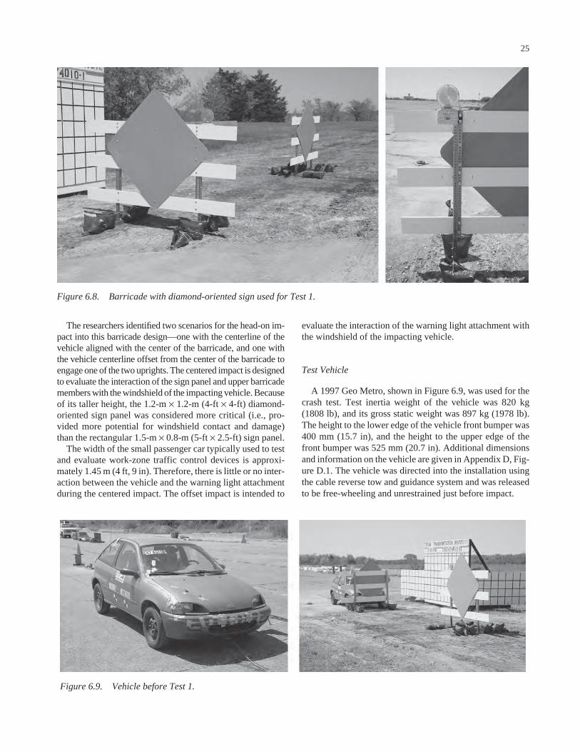
25
evaluate the interaction of the warning light attachment withthe windshield of the impacting vehicle.
Test Vehicle
A 1997 Geo Metro, shown in Figure 6.9, was used for thecrash test. Test inertia weight of the vehicle was 820 kg(1808 lb), and its gross static weight was 897 kg (1978 lb).The height to the lower edge of the vehicle front bumper was400 mm (15.7 in), and the height to the upper edge of thefront bumper was 525 mm (20.7 in). Additional dimensionsand information on the vehicle are given in Appendix D, Fig-ure D.1. The vehicle was directed into the installation usingthe cable reverse tow and guidance system and was releasedto be free-wheeling and unrestrained just before impact.
The researchers identified two scenarios for the head-on im-pact into this barricade design—one with the centerline of thevehicle aligned with the center of the barricade, and one withthe vehicle centerline offset from the center of the barricade toengage one of the two uprights. The centered impact is designedto evaluate the interaction of the sign panel and upper barricademembers with the windshield of the impacting vehicle. Becauseof its taller height, the 1.2-m × 1.2-m (4-ft × 4-ft) diamond-oriented sign panel was considered more critical (i.e., pro-vided more potential for windshield contact and damage)than the rectangular 1.5-m × 0.8-m (5-ft × 2.5-ft) sign panel.
The width of the small passenger car typically used to testand evaluate work-zone traffic control devices is approxi-mately 1.45 m (4 ft, 9 in). Therefore, there is little or no inter-action between the vehicle and the warning light attachmentduring the centered impact. The offset impact is intended to
Figure 6.8. Barricade with diamond-oriented sign used for Test 1.
Figure 6.9. Vehicle before Test 1.

Test Description
An 897-kg (1978-lb) passenger car, traveling at a speed of98.6 km/h (61.3 mi/h), impacted the first barricade head-onat 0 degrees with the centerline of the vehicle aligned withthe centerline of the barricade. Shortly after impact the bar-ricade began to move, and at 0.005 s, the bottom horizontalrail fractured. The upper portion of the barricade wrappedaround the front end of the vehicle, rotating the top of thesign panel toward the windshield. The top of the sign panelcontacted the windshield at 0.049 s, and the top and middlehorizontal rails fractured just inside the left upright at 0.056 s.At 0.058 s, the top horizontal rail fractured at the right up-right. At 0.061 s, the middle rail fractured at the right upright,and the warning light contacted the right side mirror, whichseparated from the vehicle. At 0.126 s, the vehicle lost con-tact with the sign panel and the vehicle was traveling at a speedof 84.6 km/h (52.6 mi/h).
At 0.254 s, the vehicle contacted the second barricade end-on at a speed of 83.6 km/h (51.9 mi/h) with the centerline ofthe vehicle aligned with the barricade. At 0.327 s, the secondbarricade pushed the first barricade into the windshield. Thevehicle fractured the lower horizontal rail and contacted theleft upright of the second barricade. The perforated steel tubeupright deformed around the front of the vehicle, and the endof the middle horizontal rail rotated into the hood of the vehi-cle. At 0.628 s, the vehicle exited the view of the high-speedcameras at a speed of 70.7 km/h (43.9 mi/h) with the barri-cades being pushed in front of the vehicle. Brakes on thevehicle were applied at 2.0 s after impact, and the vehiclesubsequently came to rest 64.8 m (212.6 ft) downstream ofimpact and 4.6 m (15.1 ft) to the left of centerline of impact.Although the first barricade maintained contact with thewindshield during contact with the second barricade, the sec-ond barricade only contacted the hood of the vehicle and hadno interaction with the windshield area. Thus, the secondimpact was considered to be a valid evaluation of the perfor-mance of the barricade when struck end-on. Sequential photo-graphs of the test period are in Appendix E, Figure E.1.
Test Results
Both barricades readily activated as designed by yielding andfracturing. Debris was scattered over an area 48.8 m (160.1 ft)long and 9.9 m (32.5 ft) to the left and 2.3 m (7.5 ft) to the right.The largest debris fragment weighed 23 kg (50.7 lb). The warn-ing lights remained attached to the vertical braces.
The vehicle remained upright throughout and after thecrash period. Damage to the vehicle is shown in Figure 6.10.The front bumper, hood, radiator, and radiator support weredamaged, and the right side A-post was dented. Maximumexterior crush was 250 mm (9.8 in) in the center front of thevehicle. The windshield was shattered and deformed inward50 mm (2.0 in) (a combination of Case 5 and Case 6 of theFHWA windshield damage classification criteria). There were
26
no holes or tears in the windshield, nor was the windshieldseparated from its frame.
Data from the accelerometer, located at the vehicle centerof gravity, were digitized for evaluation of occupant risk. Inthe longitudinal direction, the occupant impact velocity was3.8 m/s (12.5 ft/s) at 0.217 s, the highest 0.010-s occupantridedown acceleration was −7.8 g’s from 0.286 s to 0.296 s,and the maximum 0.050-s average acceleration was −5.0 g’sbetween 0.018 s and 0.068 s. In the lateral direction, theoccupant impact velocity was 0.3 m/s (1.0 ft/s) at 0.217 s, thehighest 0.010-s occupant ridedown acceleration was −2.1 g’sfrom 0.287 s to 0.297 s, and the maximum 0.050-s averagewas −0.9 g’s between 0.271 s and 0.321 s. These data andother pertinent information from the test are summarized inFigure 6.11. Vehicle angular displacements and accelerationsversus time traces are presented in Appendix F, Figures F.1through F.7.
A summary of the test evaluation is presented in Table 6.2.The 50-mm (2.0-in) deformation of the windshield is con-sidered to be marginally acceptable in terms of the FHWAwindshield damage classification criteria. Therefore, sincethe barricade met all other relevant evaluation criteria ofNCHRP Report 350, the perforated steel-tube barricade withwooden rails and 1.2-m × 1.2-m × 13-mm (4-ft × 4-ft × 1⁄2-in)
Figure 6.10. Damage to vehicle after Test 1.

Figure 6.11. Summary of results for Test 1.
0.000 s 0.049 s 0.172 s 0.492 s
General Information Test Agency............................... Test No. .................................... Date ...........................................Test Article Type........................................... Name .........................................
Installation Height, m (ft)............Material or Key Elements ..........
Soil Type and Condition.............Test Vehicle Type........................................... Designation................................ Model ......................................... Mass, kg Curb........................................ Test Inertial............................. Dummy ................................... Gross Static............................
Texas Transportation Institute474010-103-31-2003
Type III BarricadeType III Barricade w/Diamond Sign1.5 (5.0)Three wood barricade rails bolted to perforated steel bracesNative Soil, Dry
Production820C1997 Geo Metro
798820 77 897
Impact Conditions Angle, deg .................................
Speed, km/h (mi/h) @ 0 deg .....Speed, km/h (mi/h) @ 90 deg ...
Exit ConditionsSpeed, km/h (mi/h) ....................
Occupant Risk ValuesImpact Velocity, m/s (ft/s)
Longitudinal ............................ Lateral .................................... THIV, km/h.................................
Ridedown Accelerations, g’s Longitudinal ............................ Lateral .................................... PHD, g’s .................................... ASI ............................................Max. 0.050-s Average, g’s Longitudinal ............................ Lateral .................................... Vertical ...................................
0 & 90 98.6 (61.3)83.6 (51.9)
70.7 (43.9)
3.8 (12.5) 0.3 (1.0)13.6
-7.8-2.1 8.0 0.43
-5.0-0.9-2.1
Test Article Debris PatternLength, m (ft)....................................Width, m (ft)
Left................................................ Right ............................................Vehicle Damage Exterior VDS .............................................. CDC.............................................. Max. Exterior
Vehicle Crush, mm (in) .............. Interior OCDI............................................. Max. Occupant Compartment
Deformation, mm (in) .................Post-Impact Behavior
(during 1.0 sec after impact) Max. Yaw Angle, deg....................
Max. Pitch Angle, deg................... Max. Roll Angle, deg ....................
48.8 (160.1)
9.9 (32.5)2.3 (7.5)
12FD212FDAW2
250 (9.8)
FS0000000
50 (2.0) (windshield)
-5 4 5

plywood sign panel mounted 0.3 m (1 ft) above ground isconsidered to be marginally acceptable.
Discussion
Because the taller 1.2-m × 1.2-m (4-ft × 4-ft) diamond-oriented sign panel constitutes a more critical condition thanthe 0.8-m × 1.5-m (2.5 ft × 5 ft) rectangular sign, the success-ful test with the diamond-oriented sign panel is consideredsufficient for approving the use of the rectangular sign panel.The barricade that was tested incorporated wooden rails fab-ricated from dimensional lumber. Wooden rails are generallypreferred for their low cost, availability, ease of fabrication,and durability. Because wooden rails are considered morecritical from a crashworthiness standpoint due to their greaterweight and propensity to fracture upon impact, the successfultest with wooden rails is considered sufficient for approval ofa similar barricade design with plastic rails of lighter weight.
28
The use of the vertical braces in the barricade framing isoptional. The tested design incorporated the vertical bracesbecause their presence represents a more critical configura-tion for impact performance evaluation. Use of the verticalbraces may provide added functionality to the system. Theypermit the barricade rails and sign panel to be preassembledand then attached or detached from the barricade uprights asa unit. In absence of the vertical braces, the barricade railsand sign panel must be directly attached to the barricadeuprights to prevent the sign and fractured rails from rotatinginto the windshield of the impacting vehicle.
6.5.2 Test 2
Test Article
A second test used an offset, head-on impact condition thataligned one of the barricade uprights with the center of the
TABLE 6.2 Performance evaluation summary for Test 1Test Agency: Texas Transportation Institute Test No.: 474010-1 Test Date: 03/31/2003
NCHRP Report 350 Evaluation Criteria Test Results Assessment Structural Adequacy B. The test article should readily activate in a
predictable manner by breaking away, fracturing, or yielding.
Both barricades readily activated as designed by yielding and fracturing.
Pass
Occupant Risk D. Detached elements, fragments, or other debris
from the test article should not penetrate or show potential for penetrating the occupant compartment, or present an undue hazard to other traffic, pedestrians, or personnel in a work zone. Deformations of, or intrusions into, the occupant compartment that could cause serious injuries should not be permitted.
Debris was scattered along the vehicle path. The largest debris fragment weighed 23 kg (50.7 lb). The windshield was shattered and deformed inward 50 mm (2 in) (FHWA Case 5 and 6). There were no holes or tears in the windshield, nor was the windshield separated from its frame. There was no other measurable occupant compartment deformation.
Marginal
E. Detached elements, fragments, or other debris from the test article, or vehicular damage should not block the driverʼs vision or otherwise cause the driver to lose control of the vehicle.
The driverʼs vision was not blocked. Pass
F. The vehicle should remain upright during and after collision although moderate roll, pitching, and yawing are acceptable.
The vehicle remained upright throughout and after the crash period.
Pass
H. Occupant impact velocities should satisfy the following:
Occupant Velocity Limits (m/s)
Longitudinal occupant impact velocity was 3.8 m/s (12.5 ft/s).
Pass
Component Preferred Maximum Longitudinal 3 5
I. Occupant ridedown accelerations should satisfy the following:
Occupant Ridedown Acceleration Limits (gʼs)
Longitudinal ridedown acceleration was -7.8 gʼs, and lateral ridedown acceleration was -2.1 gʼs.
Pass
Component Preferred Maximum Longitudinal and
lateral 15 20
Vehicle Trajectory K. After collision, it is preferable that the
vehicleʼs trajectory not intrude into adjacent traffic lanes.
The vehicle continued on a straightforward path all along the trajectory path and did not intrude into adjacent lanes.
Pass*
N. Vehicle trajectory behind the test article is acceptable.
The vehicle came to rest behind the test articles.
Pass
*Criterion K preferable, not required.

vehicle. For a wide barricade, this impact condition is morelikely to occur in the field and is more conducive to evaluatingthe performance of a warning light attachment. As describedpreviously, the spacing of the barricade uprights did not per-mit evaluation of the warning light attachment in the cen-tered, head-on impact. Because a 1.2-m × 1.2-m (4-ft × 4-ft)sign panel was already found to be marginally acceptable inthe previous test, the researchers decided to use a 0.8-m ×1.5-m × 13-mm (2.5-ft × 5-ft × 1⁄2-in) rectangular plywood signpanel in the offset test. The lower rectangular panel shouldinduce less windshield damage, thereby making evaluationof any damage induced by the warning light more straight-forward.
Details of the barricade design used in Test 2, which cor-respond to Design B1 previously described, are shown inFigure 6.12. The design uses vertical braces manufacturedfrom standard 51-mm × 102-mm (2-in × 4-in) dimensionallumber. The horizontal rails and sign panel are attached tothese vertical braces. The 0.8-m × 1.5-m × 13-mm (2.5-ft ×5-ft × 1⁄2-in) rectangular plywood sign panel was mounted ata height of 0.8 m (2.5 ft) above ground. This placed the topof the sign panel flush with the top edge of the upper hori-zontal rail. The assembled rail and sign panel unit was boltedto the 38-mm (11⁄2-in) square, perforated steel-tube uprightsthrough the rails and sign panel. The uprights, which werespaced 1.37 m (4.5 ft) apart, telescope inside a 44-mm (13⁄4-in)square, 248-mm (93⁄4-in) long, perforated steel-tube sleevethat was welded to 44-mm (13⁄4-in) square, perforated steel-tube skids. The longer tube sleeves permit telescoping of theuprights to provide adjustability for placement of the barri-cade on sloping terrain.
A Type A warning light with self-contained battery com-partment was attached to the top of the left upright using a216-mm × 76-mm × 6-mm (81⁄2-in × 3-in × 1⁄4-in) steel con-nector plate. The warning light was mounted such that thelens extended above the top of the upper rail. Two barricadeswere placed in the path of the vehicle approximately 6 m (19.7 ft) apart from one another—one perpendicular to thepath of the vehicle and one parallel to the path of the vehicle.Two sandbags were placed on the front and back of each skidfor a total of eight sandbags per device. A photograph of thecompleted test installation is shown in Figure 6.13.
Test Vehicle
A 1997 Geo Metro, shown in Figure 6.14, was used forthe crash test. Test inertia weight of the vehicle was 820 kg(1808 lb), and its gross static weight was 897 kg (1978 lb).The height to the lower edge of the vehicle front bumper was400 mm (15.7 in), and the height to the upper edge of thefront bumper was 525 mm (20.7 in). Additional dimensionsand information on the vehicle are given in Appendix D, Fig-ure D.2. The vehicle was directed into the installation usingthe cable reverse tow and guidance system and was releasedto be free-wheeling and unrestrained just before impact.
29
Test Description
An 897-kg (1808-lb) vehicle, traveling at a speed of102.4 km/h (63.6 mi/h), impacted the first barricade head-onat 0 degree. The barricade was shifted 610 mm (24.0 in) tothe right to align the left barricade upright with the centerlineof the vehicle to allow a better opportunity for the vehicle tointeract with the warning light that was mounted to the top ofthe left upright. Shortly after impact, the lower horizontal railfractured, and, at 0.039 s, the center horizontal rail broke atthe right upright. The offset impact condition caused some tor-sional energy to build up in the barricade. The left side of thebarricade was being accelerated and rotated as a result of directcontact with the vehicle, while the right side of the barricaderemained relatively stationary and upright. This differentialmovement and rotation caused the barricade to twist and storeenergy. As a result, the top horizontal rail and sign panelsnapped off of the right upright at 0.058 s and subsequentlycontacted the windshield at 0.073 s. At 0.104 s, the right up-right separated from its skid, and, at 0.113 s, this uprightbroke the right side door glass.
At 0.229 s, the vehicle contacted the second barricade end-on at a speed of 83.3 km/h (51.8 mi/h) with the centerline ofthe vehicle aligned with the end of the barricade. The secondbarricade began to move at 0.244 s and became airborne at0.278 s. As in the previous test, the perforated steel-tubeupright deformed around the front of the vehicle, and the endof the middle horizontal rail rotated into the hood of the vehi-cle. At 0.537 s, the vehicle exited the view of the high-speedcameras with the barricades riding along on the front of thevehicle. At the time, the vehicle was traveling at a speed of76.7 km/h (47.7 mi/h). Brakes on the vehicle were applied at2.0 s after impact, and the vehicle subsequently came to rest74.4 m (244.1 ft) downstream of impact and 3.8 m (12.5 ft)to the right of centerline of impact. Although the first barri-cade was still in contact with the vehicle during the impactwith the second barricade, the second barricade only con-tacted the hood of the vehicle and did not interact with thewindshield area. Thus, the second impact was considered tobe a valid evaluation of the performance of the barricade whenstruck end-on. Sequential photographs of the test period areshown in Appendix E, Figure E.2.
Test Results
Both barricades readily activated at impact by yielding andfracturing. Debris was scattered over an area 56.1 m (184.0 ft)long and 1.5 m (5.0 ft) to the left and 0.8 m (2.5 ft) to theright. The warning lights remained attached to their respec-tive barricade uprights.
The vehicle remained upright throughout and after the crashperiod. Damage to the vehicle is shown in Figure 6.15. Thefront bumper, radiator, radiator support, hood, and right doorwere deformed. Maximum crush to the exterior of the vehiclewas 285 mm (11.2 in) at the center front at bumper height.The glass in the right door was completely broken out, and

Figure 6.12. Details of the barricade with rectangular sign used in Test 2.

31
Figure 6.13. Barricade with rectangular sign used in Test 2.
Figure 6.14. Vehicle before Test 2. Figure 6.15. Vehicle after Test 2.

there was a dent in the door measuring 300 mm × 200 mm ×25 mm deep (11.8 in by 7.5 in by 1 in). There was also a dentin the right side A-post with a very small hole in the windshieldnext to this dent. The windshield was shattered but intact onthe right side with no damage to the left side. The windshieldwas also deformed inward 50 mm (2.0 in). There was no othermeasurable occupant compartment deformation.
Data from the accelerometer, located at the vehicle center ofgravity, were digitized for evaluation of occupant risk andwere computed as follows. In the longitudinal direction, theoccupant impact velocity was 4.4 m/s (14.4 ft/s) at 0.286 s, thehighest 0.010-s occupant ridedown acceleration was −4.1 g’sfrom 0.286 s to 0.296 s, and the maximum 0.050-s averageacceleration was −4.6 g’s between 0.251 s and 0.301 s. In thelateral direction, the occupant impact velocity was 1.1 m/s(3.6 ft/s) at 0.286 s, the highest 0.010-s occupant ridedownacceleration was −1.7 g’s from 0.344 s to 0.354 s, and themaximum 0.050-s average was 1.0 g between 1.595 s and1.645 s. These data and other pertinent information from thetest are summarized in Figure 6.16. Vehicle angular displace-ments and accelerations versus time traces are presented inAppendix F, Figures F.8 through F.14.
The test evaluation is summarized in Table 6.3. With thesmall hole in the windshield (FHWA windshield damageclassification Case 1), the test is considered to be a failure.
Discussion
Although these test results apply only to this particulardesign, the failure mode observed in the test may apply to otherbarricades as well. Although barricades are often implementedwith lengths of 2.4 m (8 ft) or greater, they are commonlytested with shorter lengths (e.g., 1.2 m [4 ft]) to enable theimpacting vehicle to engage both supports. While the impactof both supports is indeed a critical condition for evaluatingrotation of the barricade components into the windshield, theoffset impact condition and resulting torsional failure modemay have been overlooked as another critical impact scenario.Indeed, because barricades in the field are more likely to bestruck in an offset condition than directly along their center-line, this impact condition and failure mode may need to bemore fully explored for barricades in general.
6.5.3 Test 3
Test Article
To address the problem observed in the previous test, a hor-izontal cross brace was added to the barricade to tie the twouprights together and give it more torsional rigidity. The brace,which was fabricated from 38-mm (11⁄2-in) square, perforatedsteel tubing, was placed at a height of 457 mm (18 in) (behindand below the upper edge of the lower rail) to engage the vehi-cle bumper. The objective was to get the barricade to move
32
together as a unit during an offset impact. Because of the lowmounting height, the addition of the horizontal brace shouldnot influence the impact performance for end-on impacts orcentered, head-on impacts such as those in Test 1.
Details of the barricade design evaluated in Test 3 areshown in Figure 6.17. Other than the addition of the horizon-tal brace, the barricade system was identical to the design usedin Test 2. A warning light with self-contained battery com-partment was once again attached to the top of the left barri-cade upright using a steel plate connector. The warning lightwas mounted such that the lens extended above the top of theupper rail. Two barricades were placed in the path of the vehi-cle approximately 6 m (19.7 ft) apart from one another—oneperpendicular to the path of the vehicle and one parallel tothe path of the vehicle. Two sandbags were placed on thefront and back of each skid for a total of eight sandbags perbarricade. A photograph of the completed test installation isshown in Figure 6.18.
Test Vehicle
A 1997 Geo Metro, shown in Figure 6.19, was used for thecrash test. Test inertia weight of the vehicle was 839 kg(1850 lb), and its gross static weight was 916 kg (2019 lb).The height to the lower edge of the vehicle front bumper was400 mm (15.7 in), and the height to the upper edge of thefront bumper was 525 mm (20.7 in). Additional dimensionsand information on the vehicle are given in Appendix D, Fig-ure D.3. The vehicle was directed into the installation usingthe cable reverse tow and guidance system and was releasedto be free-wheeling and unrestrained just before impact.
Test Description
A 916-kg (2019-lb) vehicle, traveling at a speed of 100.2km/h (62.3 mi /h), impacted the first barricade head-on at0 degree. The barricade was shifted 610 mm (24.0 in) to theright to align the left barricade upright with the centerline ofthe vehicle. This offset impact condition was intended to eval-uate the torsional failure mode of the barricade and provide abetter opportunity for the vehicle to interact with the warn-ing light that was mounted to the left support. Shortly afterimpact, the lower horizontal rail fractured, and, at 0.015 s, thelower horizontal rail separated from the right upright. Thecenter horizontal rail fractured at the right upright at 0.044 s.The top horizontal rail and right upright contacted the wind-shield and the side of the vehicle at 0.065 s. The end of therail that was cantilevered off the upright wrapped around theA-post and slapped and shattered the right door window. At0.145 s, the vehicle lost contact with the first barricade, andthe vehicle was traveling at a speed of 85.3 km/h (53.0 mi/h).
At 0.145 s, the vehicle contacted the second barricade end-on at a speed of 81.3 km/h (50.5 mi/h) with the centerline ofthe vehicle aligned with the end of the barricade. Shortly

Figure 6.16. Summary of results for Test 2.
0.000 s 0.099 s 0.296 s 0.444 s
General Information Test Agency............................... Test No. .................................... Date ........................................... Test Article Type........................................... Name ......................................... Installation Height, m (ft)............ Material or Key Elements .......... Soil Type and Condition............. Test Vehicle Type........................................... Designation................................ Model ......................................... Mass, kg (lb) Curb........................................ Test Inertial............................. Dummy ................................... Gross Static............................
Texas Transportation Institute 474010-2 03-31-2003 Type III Barricade Type III Barricade w/Rectangular Sign 1.5 (5.0) Three wood barricade rails and braces bolted to perforated steel legs Native Soil, Dry Production 820C 1997 Geo Metro 861 820 77 897
Impact Conditions Angle, deg ................................. Speed, km/h (mi/h) @ 0 deg ..... Speed, km/h (mi/h) @ 90 deg ... Exit Conditions Speed, km/h (mi/h) .................... Occupant Risk Values Impact Velocity, m/s (ft/s) Longitudinal ............................ Lateral .................................... THIV, km/h................................. Ridedown Accelerations, g’s Longitudinal ............................ Lateral .................................... PHD, g’s .................................... ASI ............................................ Max. 0.050-s Average, g’s Longitudinal ............................ Lateral .................................... Vertical ...................................
0 & 90 102.4 (63.6) 83.3 (51.8) 76.7 (47.7) 4.4 (14.4) 1.1 (3.6) 16.2 -4.1 -1.7 3.9 0.40 -4.6 1.0 1.1
Test Article Debris Pattern Length, m (ft).................................... Width, m (ft) Left................................................ Right ............................................Vehicle Damage Exterior VDS .............................................. CDC.............................................. Max. Exterior Vehicle Crush, mm (in) .............. Interior OCDI............................................. Max. Occupant Compartment Deformation, mm (in).................Post-Impact Behavior (during 1.0 sec after impact) Max. Yaw Angle, deg.................... Max. Pitch Angle, deg................... Max. Roll Angle, deg ....................
56.1 (184.0) 1.5 (5.0) 0.8 (2.5) 12FD2 12FDAW2 285 (11.2) FS0000000 50 (2.0) (windshield) 22 10 -23

after impact, the barricade began to move, and, at 0.286 s, thebarricade became airborne. As in the previous tests, the per-forated steel-tube upright deformed around the front of thevehicle, and the end of the barricade rotated into the hood ofthe vehicle without contacting the windshield. At 0.491 s, thevehicle lost contact with the second barricade while travel-ing at a speed of 75.7 km/h (47.0 mi/h). Brakes on the vehiclewere applied at 3.9 s. The vehicle subsequently came to rest87.7 m (287.8 ft) downstream of impact and 3.8 m (12.5 ft)to the left of centerline. Sequential photographs of the testperiod are shown in Appendix E, Figure E.3.
Test Results
Both barricades readily activated at impact by yielding andfracturing. Debris was scattered over an area 49.6 m (162.7 ft)long and 3.8 m (12.5 ft) to the left and 3.8 m (12.5 ft) to theright of the initial point of vehicle contact. The largest of the
34
debris weighed 20 kg (44.1 lb). The warning light remainedattached to both barricades and did not result in any occupantcompartment deformation.
Damage to the vehicle is shown in Figure 6.20. The frontbumper, radiator, radiator support, hood, right front quarterpanel, right door, and right rear quarter panel were deformed.Maximum crush to the exterior of the vehicle was 260 mm(10.2 in) at the center front at bumper height. The glass in theright door was completely broken out by contact with one ofthe barricade rails, but high-speed film indicated there was nointrusion of the barricade rail into the passenger compart-ment. There were dents in the right side A-post and rockerpanel. The windshield was shattered on the right side butwas intact and not deformed inward (FHWA windshielddamage classification Case 5). The left side of the windshieldsustained only minimal damage. There was no measurableoccupant compartment deformation. The vehicle remainedupright during and after the crash period.
TABLE 6.3 Performance evaluation summary for Test 2
Test Agency: Texas Transportation Institute Test No.: 474010-2 Test Date: 03/31/2003NCHRP Report 350 Evaluation Criteria Test Results Assessment
Structural Adequacy B. The test article should readily activate in a
predictable manner by breaking away, fracturing, or yielding.
Both barricades readily activated as designed by yielding and fracturing.
Pass
Occupant Risk D. Detached elements, fragments, or other debris
from the test article should not penetrate or show potential for penetrating the occupant compartment, or present an undue hazard to other traffic, pedestrians, or personnel in a work zone. Deformations of, or intrusions into, the occupant compartment that could cause serious injuries should not be permitted.
Debris was scattered along the vehicle path. The windshield had a very small hole (FHWA Case 1) and was shattered but intact on the right side. There was no damage to the left side of the windshield. The windshield was deformed inward 50 mm (2.0 in). There was no other measurable occupant compartment deformation.
Fail
E. Detached elements, fragments, or other debris from the test article, or vehicular damage should not block the driver’s vision or otherwise cause the driver to lose control of the vehicle.
The driverís vision was not blocked. Pass
F. The vehicle should remain upright during and after collision although moderate roll, pitching, and yawing are acceptable.
The vehicle remained upright throughout and after the crash period.
Pass
H. Occupant impact velocities should satisfy the following:
Occupant Velocity Limits (m/s)
Longitudinal occupant impact velocity was 4.4 m/s (14.4 ft/s).
Pass
Component Preferred Maximum Longitudinal 3 5
I. Occupant ridedown accelerations should satisfy the following:
Occupant Ridedown Acceleration Limits (g’s) Component Preferred Maximum Longitudinal and
lateral 15 20
Longitudinal ridedown acceleration was -4.1 g’s, and lateral ridedown acceleration was -1.7 g’s.
Pass
Vehicle Trajectory K. After collision, it is preferable that the
vehicle’s trajectory not intrude into adjacent traffic lanes.
The vehicle continued on a straightforward path all along the trajectory path and did not intrude into adjacent lanes.
Pass *
N. Vehicle trajectory behind the test article is acceptable.
The vehicle came to rest behind the test articles.
Pass
*Criterion K preferable, not required.
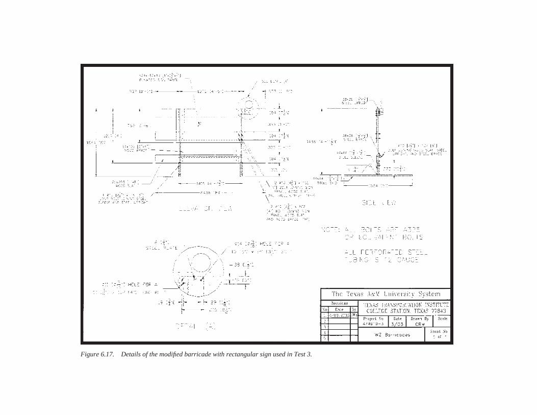
Figure 6.17. Details of the modified barricade with rectangular sign used in Test 3.

Data from the accelerometer, located at the vehicle centerof gravity, were digitized for evaluation of occupant risk andwere computed as follows. In the longitudinal direction, theoccupant impact velocity was 2.9 m/s (9.5 ft/s) at 0.248 s, thehighest 0.010-s occupant ridedown acceleration was −7.6 g’sfrom 0.277 s to 0.287 s, and the maximum 0.050-s average
36
acceleration was −4.1 g’s between 0.002 s and 0.052 s. Inthe lateral direction, the occupant impact velocity was 0.6 m/s(2.0 ft/s) at 0.248 s, the highest 0.010-s occupant ridedownacceleration was 2.6 g’s from 0.282 s to 0.292 s, and themaximum 0.050-s average was 1.2 g’s between 0.243 s and0.293 s. These data and other pertinent information fromthe test are summarized in Figure 6.21. Vehicle angular
Figure 6.19. Vehicle before Test 3.Figure 6.18. Modified barricade with rectangular signused in Test 3.
Figure 6.20. Vehicle after Test 3.

Figure 6.21. Summary of results for Test 3.
0.000 s 0.098 s 0.294 s 0.417 s
General Information Test Agency............................... Test No. .................................... Date ........................................... Test Article Type........................................... Name ......................................... Installation Height, m (ft)............ Material or Key Elements .......... Soil Type and Condition............. Test Vehicle Type........................................... Designation................................ Model ......................................... Mass, kg Curb........................................ Test Inertial............................. Dummy ................................... Gross Static............................
Texas Transportation Institute 474010-3 04-08-2003 Type III Barricade Type III Barricade w/Rectangular Sign 1.5 (5.0) Three wood barricade rails and braces bolted to perforated steel legs Native Soil, Dry Production 820C 1997 Geo Metro 857 839 77 916
Impact Conditions Angle, deg ................................. Speed, km/h (mi/h) @ 0 deg ..... Speed, km/h (mi/h) @ 90 deg ... Exit Conditions Speed, km/h (mi/h) .................... Occupant Risk Values Impact Velocity, m/s (ft/s) Longitudinal ............................ Lateral .................................... THIV, km/h................................. Ridedown Accelerations, g’s Longitudinal ............................ Lateral .................................... PHD, g’s .................................... ASI ............................................ Max. 0.050-s Average, g’s Longitudinal ............................ Lateral .................................... Vertical ...................................
0 & 90 100.2 (62.3)81.3 (50.5) 75.7 (47.0) 2.9 (9.5) 0.6 (2.0) 10.3 -7.6 2.6 7.7 0.34 -4.1 1.2 -1.0
Test Article Debris Pattern Length, m (ft).................................... Width, m (ft) Left................................................ Right ............................................Vehicle Damage Exterior VDS .............................................. CDC.............................................. Max. Exterior Vehicle Crush, mm (in) .............. Interior OCDI............................................. Max. Occupant Compartment Deformation, mm (in).................Post-Impact Behavior (during 1.0 sec after impact) Max. Yaw Angle, deg.................... Max. Pitch Angle, deg................... Max. Roll Angle, deg ....................
49.6 (162.7) 3.8 (12.5) 3.8 (12.5) 12FD2 12FDAW2 260 (10.2) FS0000000 0 12 11 6
displacements and accelerations versus time traces are pre-sented in Appendix F, Figures F.15 through F.21.
The test evaluation is summarized in Table 6.4. The barri-cade met all required evaluation criteria for both the head-onand end-on impact scenarios.
Discussion
Although the upper rail and sign panel still contacted the A-post and windshield, the horizontal brace induced movementin the right barricade upright as intended. The movement of theupright limited the torsional energy stored in the barricade,thus reducing the contact force imparted by the rails and signpanel to the windshield and limiting the resulting windshielddamage to acceptable levels. This result is proved by the wind-shield being only cracked and not deformed inward.
38
6.5.4 Test 4
Test Article
Having successfully tested the perforated steel-tube barri-cade, the researchers used the final test to evaluate the per-formance of a barricade fabricated from wood and HPPL.Details of the barricade design, which correspond to DesignB3 previously described, are shown in Figure 6.22. The bar-ricade uprights were 102-mm (4-in) square HPPL manufac-tured from HDPE. The uprights were bolted between the legsof the 51-mm × 152-mm (2-in × 6-in) wood skids in two loca-tions to form a moment connection to resist rotation. Shortlengths of the (102-mm [4-in] square) HPPL were used asspacers at the front and back of the skids. As with the steel-frame barricade designs, the 12-mm × 203-mm (1-in × 8-in)
TABLE 6.4 Performance evaluation summary for Test 3
Test Agency: Texas Transportation Institute Test No.: 474010-3 Test Date: 04/08/2003NCHRP Report 350 Evaluation Criteria Test Results Assessment
Structural Adequacy B. The test article should readily activate in a
predictable manner by breaking away, fracturing, or yielding.
Both barricades readily activated as designed by yielding and fracturing.
Pass
Occupant Risk D. Detached elements, fragments, or other debris
from the test article should not penetrate or show potential for penetrating the occupant compartment, or present an undue hazard to other traffic, pedestrians, or personnel in a work zone. Deformations of, or intrusions into, the occupant compartment that could cause serious injuries should not be permitted.
Debris was scattered along the vehicle path. The largest debris was 20.0 kg (44.1 lb). The windshield was shattered on the right side but was intact and not deformed inward (FHWA Case 5). The left side of the windshield sustained only minimal damage. The glass in the right door was broken out by contact with one of the rails, but there was no intrusion of the rail into the passenger compartment. There was no measurable occupant compartment deformation.
Pass
E. Detached elements, fragments, or other debris from the test article, or vehicular damage should not block the driver’s vision or otherwise cause the driver to lose control of the vehicle.
The driver’s vision was not blocked. Pass
F. The vehicle should remain upright during and after collision although moderate roll, pitching, and yawing are acceptable.
The vehicle remained upright throughout and after the crash period.
Pass
H. Occupant impact velocities should satisfy the following:
Occupant Velocity Limits (m/s) Component Preferred Maximum Longitudinal 3 5
Longitudinal occupant impact velocity was 2.9 m/s (9.5 ft/s).
Pass
I. Occupant ridedown accelerations should satisfy the following:
Occupant Ridedown Acceleration Limits (g’s) Component Preferred Maximum Longitudinal and
lateral 15 20
Longitudinal ridedown acceleration was -7.6 g’s, and lateral ridedown acceleration was 2.6 g’s.
Pass
Vehicle Trajectory K. After collision, it is preferable that the
vehicle’s trajectory not intrude into adjacent traffic lanes.
The vehicle continued on a straightforward path all along the trajectory path and did not intrude into adjacent lanes.
Pass*
N. Vehicle trajectory behind the test article is acceptable.
The vehicle came to rest behind the test articles.
Pass
*Criterion K preferable, not required.
Figure 6.22. Details of hollow-HDPE/wooden barricade with rectangular sign used in Test 4.
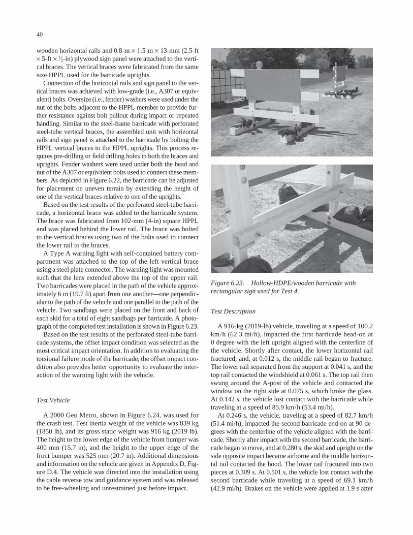
wooden horizontal rails and 0.8-m × 1.5-m × 13-mm (2.5-ft× 5-ft × 1⁄2-in) plywood sign panel were attached to the verti-cal braces. The vertical braces were fabricated from the samesize HPPL used for the barricade uprights.
Connection of the horizontal rails and sign panel to the ver-tical braces was achieved with low-grade (i.e., A307 or equiv-alent) bolts. Oversize (i.e., fender) washers were used under thenut of the bolts adjacent to the HPPL member to provide fur-ther resistance against bolt pullout during impact or repeatedhandling. Similar to the steel-frame barricade with perforatedsteel-tube vertical braces, the assembled unit with horizontalrails and sign panel is attached to the barricade by bolting theHPPL vertical braces to the HPPL uprights. This process re-quires pre-drilling or field drilling holes in both the braces anduprights. Fender washers were used under both the head andnut of the A307 or equivalent bolts used to connect these mem-bers. As depicted in Figure 6.22, the barricade can be adjustedfor placement on uneven terrain by extending the height of one of the vertical braces relative to one of the uprights.
Based on the test results of the perforated steel-tube barri-cade, a horizontal brace was added to the barricade system.The brace was fabricated from 102-mm (4-in) square HPPLand was placed behind the lower rail. The brace was boltedto the vertical braces using two of the bolts used to connectthe lower rail to the braces.
A Type A warning light with self-contained battery com-partment was attached to the top of the left vertical braceusing a steel plate connector. The warning light was mountedsuch that the lens extended above the top of the upper rail.Two barricades were placed in the path of the vehicle approx-imately 6 m (19.7 ft) apart from one another—one perpendic-ular to the path of the vehicle and one parallel to the path of thevehicle. Two sandbags were placed on the front and back ofeach skid for a total of eight sandbags per barricade. A photo-graph of the completed test installation is shown in Figure 6.23.
Based on the test results of the perforated steel-tube barri-cade systems, the offset impact condition was selected as themost critical impact orientation. In addition to evaluating thetorsional failure mode of the barricade, the offset impact con-dition also provides better opportunity to evaluate the inter-action of the warning light with the vehicle.
Test Vehicle
A 2000 Geo Metro, shown in Figure 6.24, was used forthe crash test. Test inertia weight of the vehicle was 839 kg(1850 lb), and its gross static weight was 916 kg (2019 lb).The height to the lower edge of the vehicle front bumper was400 mm (15.7 in), and the height to the upper edge of thefront bumper was 525 mm (20.7 in). Additional dimensionsand information on the vehicle are given in Appendix D, Fig-ure D.4. The vehicle was directed into the installation usingthe cable reverse tow and guidance system and was releasedto be free-wheeling and unrestrained just before impact.
40
Test Description
A 916-kg (2019-lb) vehicle, traveling at a speed of 100.2km/h (62.3 mi/h), impacted the first barricade head-on at 0 degree with the left upright aligned with the centerline ofthe vehicle. Shortly after contact, the lower horizontal railfractured, and, at 0.012 s, the middle rail began to fracture.The lower rail separated from the support at 0.041 s, and thetop rail contacted the windshield at 0.061 s. The top rail thenswung around the A-post of the vehicle and contacted thewindow on the right side at 0.075 s, which broke the glass.At 0.142 s, the vehicle lost contact with the barricade whiletraveling at a speed of 85.9 km/h (53.4 mi/h).
At 0.246 s, the vehicle, traveling at a speed of 82.7 km/h(51.4 mi/h), impacted the second barricade end-on at 90 de-grees with the centerline of the vehicle aligned with the barri-cade. Shortly after impact with the second barricade, the barri-cade began to move, and at 0.280 s, the skid and upright on theside opposite impact became airborne and the middle horizon-tal rail contacted the hood. The lower rail fractured into twopieces at 0.309 s. At 0.501 s, the vehicle lost contact with thesecond barricade while traveling at a speed of 69.1 km/h(42.9 mi/h). Brakes on the vehicle were applied at 1.9 s after
Figure 6.23. Hollow-HDPE/wooden barricade withrectangular sign used for Test 4.

impact. The vehicle subsequently came to rest 54.5 m (178.8 ft)downstream of impact and 3.1 m (10.2 ft) to the right of center-line. Sequential photographs of the test period are shown inAppendix E, Figure E.4.
Test Results
Both barricades readily activated at impact by yielding andfracturing. The second barricade came to rest under the vehi-cle. The next largest piece of debris weighed approximately22 kg (48.5 lb). The debris was scattered over an area 54.5 m(178.8 ft) long and 3.1 m (10.2 ft) to the right of the initialimpact point. The warning light remained attached to bothbarricades and did not result in any occupant compartmentdeformation.
Damage to the vehicle is shown in Figure 6.25. The frontbumper, radiator, radiator support, hood, and right doorwere deformed. Maximum crush to the exterior of the vehi-cle was 220 mm (8.7 in) at the center front at bumper height.There was a dent in the right side A-post, and the wind-shield was shattered on the right side but remained intactand was not deformed inward (FHWA windshield damageclassification Case 5). The left side of the windshield sus-
41
tained only minimal damage. The glass in the right door wascompletely broken out by contact with the end of the top railafter it folded around the A-post. The high-speed film indi-cated that the end of the rail intruded a couple inches beyondthe door glass into the passenger compartment. There was ahole cut in the hood and a dent in the lower center of the door.There was no other measurable occupant compartment de-formation. The vehicle remained upright during and after thecollision event.
Data from the accelerometer, located at the vehicle centerof gravity, were digitized for evaluation of occupant risk andwere computed as follows. In the longitudinal direction, theoccupant impact velocity was 2.9 m/s (9.5 ft/s) at 0.269 s, thehighest 0.010-s occupant ridedown acceleration was −8.4 g’sfrom 0.286 s to 0.296 s, and the maximum 0.050-s averageacceleration was −5.1 g’s between 0.268 s and 0.318 s. In thelateral direction, the occupant impact velocity was 0.7 m/s(2.3 ft/s) at 0.269 s, the highest 0.010-s occupant ridedownacceleration was 1.8 g’s from 0.281 s to 0.291 s, and the max-imum 0.050-s average was 1.0 g between 1.692 s and 1.742 s.These data and other pertinent information from the test aresummarized in Figure 6.26. Vehicle angular displacementsand accelerations versus time traces are presented in Appen-dix F, Figures F.22 through F.28.
Figure 6.24. Vehicle before Test 4. Figure 6.25. Damage to vehicle after Test 4.
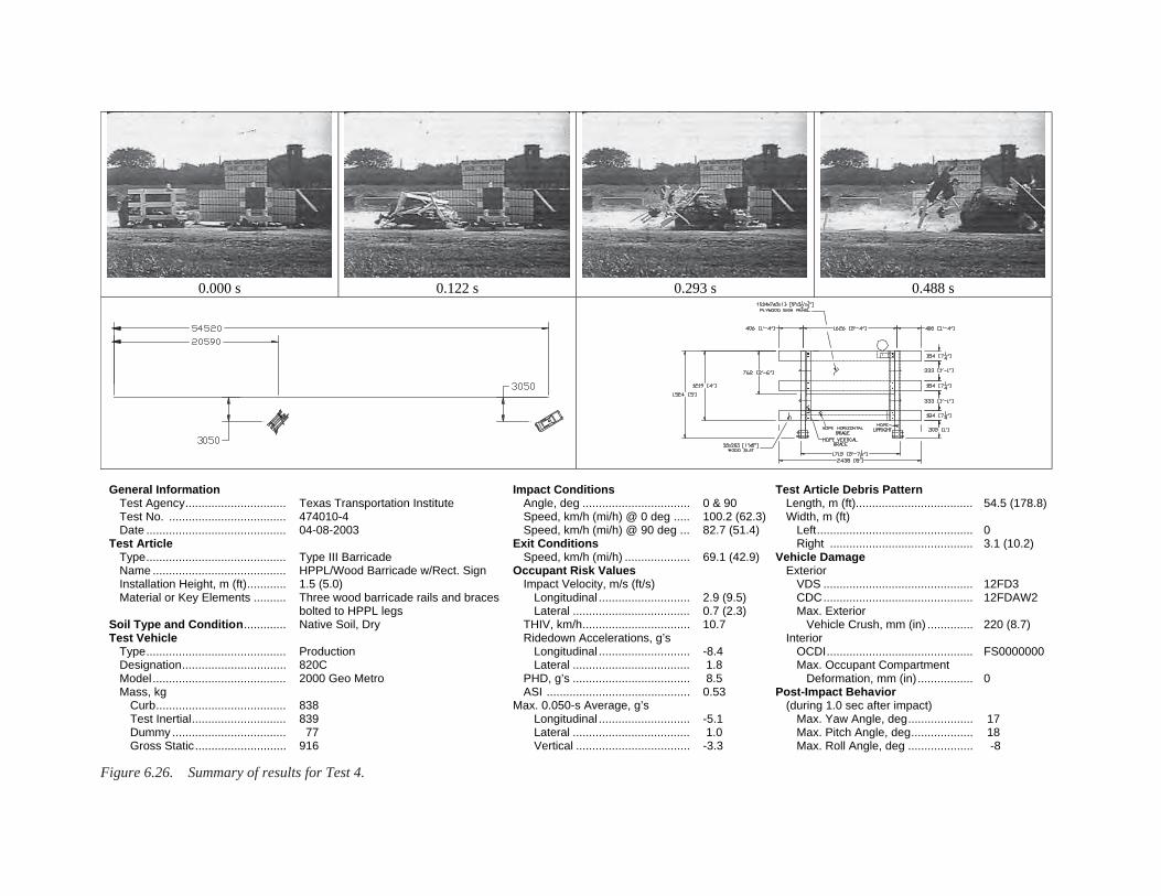
Figure 6.26. Summary of results for Test 4.
0.000 s 0.122 s 0.293 s 0.488 s
General Information Test Agency............................... Test No. .................................... Date ........................................... Test Article Type........................................... Name ......................................... Installation Height, m (ft)............ Material or Key Elements .......... Soil Type and Condition............. Test Vehicle Type........................................... Designation................................ Model ......................................... Mass, kg Curb........................................ Test Inertial............................. Dummy ................................... Gross Static............................
Texas Transportation Institute 474010-4 04-08-2003 Type III Barricade HPPL/Wood Barricade w/Rect. Sign 1.5 (5.0) Three wood barricade rails and braces bolted to HPPL legs Native Soil, Dry Production 820C 2000 Geo Metro 838 839 77 916
Impact Conditions Angle, deg ................................. Speed, km/h (mi/h) @ 0 deg ..... Speed, km/h (mi/h) @ 90 deg ... Exit Conditions Speed, km/h (mi/h) .................... Occupant Risk Values Impact Velocity, m/s (ft/s) Longitudinal ............................ Lateral .................................... THIV, km/h................................. Ridedown Accelerations, g’s Longitudinal ............................ Lateral .................................... PHD, g’s .................................... ASI ............................................ Max. 0.050-s Average, g’s Longitudinal ............................ Lateral .................................... Vertical ...................................
0 & 90 100.2 (62.3)82.7 (51.4) 69.1 (42.9) 2.9 (9.5) 0.7 (2.3) 10.7 -8.4 1.8 8.5 0.53 -5.1 1.0 -3.3
Test Article Debris Pattern Length, m (ft).................................... Width, m (ft) Left................................................ Right ............................................Vehicle Damage Exterior VDS .............................................. CDC.............................................. Max. Exterior Vehicle Crush, mm (in) .............. Interior OCDI............................................. Max. Occupant Compartment Deformation, mm (in).................Post-Impact Behavior (during 1.0 sec after impact) Max. Yaw Angle, deg.................... Max. Pitch Angle, deg................... Max. Roll Angle, deg ....................
54.5 (178.8) 0 3.1 (10.2) 12FD3 12FDAW2 220 (8.7) FS0000000 0 17 18 -8

The test evaluation is summarized in Table 6.5. The barri-cade met all required evaluation criteria for both the head-onand end-on impact scenarios.
Discussion
Although the right side door window was shattered bythe end of the upper rail, the slight intrusion of the railbeyond the window was not considered to constitute a risk
43
of serious injury in a frontal collision. This behavior can bemitigated by reducing the overhang distance of the barri-cade rails past the uprights. The spacing of the uprights islimited by the width of the sign panel, which must be attachedto either the uprights or vertical braces. By increasing thespacing of the uprights from 1.4 m to 1.6 m (4 ft, 6 in to 5 ft, 4 in) (see Figure 6.27), the overhang distance of thebarricade rails is reduced from 0.5 m to 0.4 m (1 ft, 9 in to1 ft, 4 in).
TABLE 6.5 Performance evaluation summary for Test 4Test Agency: Texas Transportation Institute Test No.: 474010-4 Test Date: 04/08/2003
NCHRP Report 350 Evaluation Criteria Test Results Assessment Structural Adequacy B. The test article should readily activate in a
predictable manner by breaking away, fracturing, or yielding.
Both barricades readily activated as designed by yielding and fracturing.
Pass
Occupant Risk D. Detached elements, fragments, or other debris
from the test article should not penetrate or show potential for penetrating the occupant compartment, or present an undue hazard to other traffic, pedestrians, or personnel in a work zone. Deformations of, or intrusions into, the occupant compartment that could cause serious injuries should not be permitted.
The second barricade came to rest under the vehicle. The remaining debris was scattered along the vehicle path with the largest weighing 22.0 kg (48.5 lb). The windshield was shattered on the right side but was intact and not deformed inward (FHWA Case 5). The left side of the windshield sustained only minimal damage. The end of one of the rails folded around the A-post and broke out the glass in the right door. The end of the rail intruded a couple inches beyond the door glass into the passenger compartment, but was not considered to constitute a potential for serious injury in a frontal collision. There was no measurable occupant compartment deformation.
Pass
E. Detached elements, fragments, or other debris from the test article, or vehicular damage should not block the driverʼs vision or otherwise cause the driver to lose control of the vehicle.
The driverʼs vision was not blocked. Pass
F. The vehicle should remain upright during and after collision although moderate roll, pitching, and yawing are acceptable.
The vehicle remained upright throughout and after the crash period.
Pass
H. Occupant impact velocities should satisfy the following:
Occupant Velocity Limits (m/s) Component Preferred Maximum Longitudinal 3 5
Longitudinal occupant impact velocity was 2.9 m/s (9.5 ft/s).
Pass
I. Occupant ridedown accelerations should satisfy the following:
Occupant Ridedown Acceleration Limits (gʼs) Component Preferred Maximum Longitudinal and
lateral 15 20
Longitudinal ridedown acceleration was -8.4 gʼs, and lateral ridedown acceleration was 1.8 gʼs.
Pass
Vehicle Trajectory K. After collision, it is preferable that the
vehicleʼs trajectory not intrude into adjacent traffic lanes.
The vehicle continued on a straightforward path all along the trajectory path and did not intrude into adjacent lanes.
Pass*
N. Vehicle trajectory behind the test article is acceptable.
The vehicle came to rest behind the test articles.
Pass
*Criterion K preferable, not required.

44
Figure 6.27. Barricade with increased spacing of upright.
45
CHAPTER 7
LOW-MOUNTING-HEIGHT SIGN SUPPORTS WITH RIGID SIGN SUBSTRATES
One of the devices selected by the panel for developmentunder Phase II of the project was a low-mounting-height,generic sign support system with rigid substrate that can befabricated from inexpensive, readily available materials. Mostof the acceptable alternatives currently available are propri-etary sign stands that must be used in combination with a roll-up–type fabric or vinyl sign panel. Although some of thesesystems can offer advantages such as portability, ease of erec-tion, and adjustable mounting height, their cost can some-times be prohibitive.
Factors that can affect the impact performance of a signsupport system include but are not limited to the mass of theprimary components, failure mode of the structural members,connection details between the structural members, sign sub-strate material, sign panel size, and sign panel mounting height.Research has demonstrated the need to design and evaluatea portable sign support as a system consisting of a supportstructure and a sign substrate. In several instances, crash test-ing has demonstrated that a particular support structure canbe crashworthy for one type of sign substrate but not anotherand vice versa.
Rigid sign substrates fabricated from materials such as ply-wood are sometimes preferred by user agencies and contractorsbecause of their low cost, availability, rigidity, durability, andease of fabrication. Whereas the legibility and retro-reflectivityof vinyl roll-up signs supported on flexible stays may be re-duced in windy conditions because of their propensity to leanand deflect, the rigidity of a plywood sign panel enables it toretain its shape and orientation in windy conditions. How-ever, while these characteristics are desirable from a func-tional standpoint, the rigidity and mass of a plywood signpanel make plywood more critical than other substrate ma-terials from a crashworthiness standpoint. Because of itsgreater weight, a successful test with a plywood substrate isgenerally considered to be sufficient for receiving approvalof a similar sign support with a comparably sized aluminumsign substrate.
In addition to being crashworthy, the support and base towhich the sign substrate is mounted must provide sufficientstrength and stability to accommodate wind and other serviceloads. A generic sign support fabricated from perforated steeltubing or angle has many desirable attributes. With the lowmounting height, it is desirable to prevent or at least signifi-cantly delay fracture and/or separation of the uprights from
the base or skids, thus reducing the potential for the detacheduprights and sign panel to rotate into the windshield. The duc-tility of tubular or angle steel uprights permits them to ini-tially yield and wrap around the front end of the vehicle. Ona paved surface, the sign support system is then carried alongby the vehicle as a unit until the vehicle comes to a stop. Bykeeping the structure intact and reducing or eliminating theseparation of components that might penetrate the windshield,the probability of occupant compartment intrusion is reduced.On a dirt surface, the translational motion of the sign supportsystem can be impeded if the system’s legs or skids dig intothe ground. Under such circumstances, the increased momentgenerated on the uprights can eventually cause them to frac-ture and release from the skids. However, by this time, momen-tum has been transferred to the sign support components andthe relative speed between the sign support projectile andvehicle is significantly reduced.
7.1 DESIGN ALTERNATIVES
Per instructions from the project panel, the mounting heightfrom the ground to the bottom of the sign panel was taken tobe 305 mm (12 in) for the proposed sign support designs. Ata 305-mm (12-in) mounting height, the top of a diamond-oriented 1.2-m × 1.2-m (4-ft × 4-ft) sign panel is approxi-mately 2.0 m (6.7 ft) above the ground. For a Geo Metro,which is the typical vehicle used to represent the 820C designvehicle specified in NCHRP Report 350, the distance fromthe ground, around the bumper, and across the hood to thebase of the windshield is approximately 1.6 m (5.25 ft). There-fore, it is anticipated that as the support structure yields aroundthe front end of the test vehicle during a 0-degree impact, thetop of the sign panel will contact the windshield. However,the low mounting height provides some direct contact andacceleration to the sign panel, thereby reducing the contactvelocity with the windshield. During a 90-degree impact, thecorner of the sign panel should initially contact the hood,rather than the windshield, as it rotates toward the vehicle.Thus, although some windshield damage is expected, a rigidsign substrate was thought to have a reasonable probabilityof meeting impact performance requirements when incor-porated into a sign support system at a mounting height of305 mm (12 in).

Once the basic characteristics of the system (e.g., mountingheight, sign substrate, support material type) were defined, aneffort was made to develop design alternatives that providesome desirable functional characteristics. Durability, handling,fabrication/repair, and site adaptability were considered.
Most of the designs developed incorporate square, perfo-rated steel tubing as the support material. Holes punched on allfaces of the 25-mm (1-in) square supports simplify construc-tion and adjustability. Cost could be reduced if angle shapesare substituted for the tubular structural members. In eithercase, the galvanized steel will provide good durability andresistance to environmental attack. In regard to handling, sys-tems composed of perforated steel tubing or angles can gener-ally be readily assembled for relatively quick on-site deploy-ment and disassembled for ease of transportation. The boltedconnections used in these systems facilitate repair by permit-ting selected components to be readily removed and replaced.
The degree of site adaptability (i.e., the degree of adjust-ment that a device provides to accommodate variations in fieldconditions) varies among the different design alternatives.Some of the designs that are least expensive to construct donot have a high degree of adjustability. Designs with a highdegree of site adaptability tend to be more complex and ex-pensive to construct.
46
A total of eight low-mounting-height, small sign supportdesigns were developed for review and prioritization by theproject panel. The following sections briefly summarize eachof these systems.
7.1.1 Design L1: Independent Dual Uprights
The sign support shown in Figure 7.1 uses two identicalbut independent uprights to support the plywood sign panel.The use of two uprights improves the torsional stability of thesign panel. Short sleeves are welded to 1.2-m (4-ft) long skids.Uprights are inserted and bolted into the sleeves. The rigidsign panel is then bolted to the uprights with a minimum oftwo bolts in each. The sign panel serves as the cross bracingfor the system. Transportation and erection is facilitated bythe removal of bolts connecting the uprights to the skids.While the design is simple, there is only minimal adjustabil-ity to account for varying terrain considerations. Although itmay not be needed, there is no front-to-back tilt adjustmentto accommodate vertical grade. If the sign support is placedon the roadside, horizontal slope can be accommodated byadjusting the height of the downhill upright by either extend-ing the tube out of the sleeve and/or lowering the attachmentpoints to the sign panel.
Figure 7.1. Design L1: independent dual uprights.

7.1.2 Design L2: H-Base with Single Upright
The sign support shown in Figure 7.2 has an H-shapedbase with single center upright. The central member of theH-shaped base is welded to the center of each skid. A shortsleeve is then welded to the center of this cross member. Anupright is inserted and bolted into the sleeve. The rigid signpanel is then mounted to the single upright using a minimumof two bolts. This design is relatively simple and is compa-rable to Design L1 in terms of material quantities. It requiresfewer bolts but more welding than Design L1. Assembly anddisassembly is faster because there is only one upright with asingle bolt or pin to insert or remove. However, signs mountedon single vertical supports will be more susceptible to flutterin windy conditions. This design does not possess any side-to-side or front-to-back adjustability.
7.1.3 Design L3: Pivoting Dual Uprights
Design L3, shown in Figure 7.3, is similar in many respectsto Design L1. However, this design incorporates some front-to-back adjustability by using pin plates at the base of eachupright. These adjustment plates can be either welded orbolted to the skids. The plates are used to attach the 305-mm
47
(12-in) long sleeves to the skids. Similar to Design L1, theuprights insert and bolt into the sleeves. The rigid sign panelis then bolted to the uprights with a minimum of two bolts ineach vertical member.
To tilt the sign panel to the front or back, the upper adjust-ment bolt/pin is removed and reinserted after aligning thesleeve with one of the other holes in the plate. As with DesignL1, side-to-side adjustment can be accommodated by tele-scoping of one of the vertical members inside its sleeve oradjusting the attachment of one of the uprights to the signpanel. The top adjusting pin on each plate can be removed tolay the sign down for easy transport as a single unit. If desired(for ease of repair, etc.), the sign panel and uprights can bereadily detached from the base by removing the bolts throughthe sleeves.
7.1.4 Design L4: H-Base with Dual Uprights
The H-base shown in Figure 7.4 is a combination of De-signs L1 and L2. It uses the H-base in combination with twouprights. The cross member can be attached to the skids usingsleeves as shown or by direct welding (see Design L2). Thisdesign uses a little more material and requires a little morewelding than Design L2, but should be more stable and elim-
Figure 7.2. Design L2: H-base with single upright.

48
Figure 7.3. Design L3: pivoting dual uprights.
Figure 7.4. Design L4: H-base with dual uprights.

inate flutter. As with Design L2, the H-base with dual uprightsdoes not have side-to-side or front-to-back adjustability.
7.1.5 Design L5: X-Base with Single Upright
Another alternative for a single upright is the X-base shownin Figure 7.5. The details of the base connection are shown inDetail B of the drawing. Sleeves are welded to the center of a1.2-m (4-ft) long skid on three sides. The two horizontal sleevesaccept a short piece of perforated tubing to complete the X-base. The upright is inserted and bolted to the vertical sleeve.The rigid sign panel is bolted to the upright at two locations.
This system is lighter in weight than the other designs be-cause less material is used. As with Design L2, some flutter ofthe sign is anticipated in strong winds. Removal of the bolt con-necting the upright to the base allows for easy transport of thesystem in two sections. As with the H-bases, the X-base designdoes not possess side-to-side or front-to-back adjustability.
7.1.6 Design L6: X-Base with Pivoting Upright
Design L6, shown in Figure 7.6, incorporates the adjust-ing plate used in Design L3 with the X-base used in Design
49
L5 to provide side-to-side or front-to-back adjustment on asingle vertical support. The horizontal sleeves are welded tothe adjusting plates, which in turn are welded or bolted to theskid. The two horizontal sleeves accept a short piece of per-forated tubing to complete the X-base. The upright is insertedand bolted into the vertical sleeve. The rigid sign panel isbolted to the upright at two locations.
The adjustment plates can be used to provide side-to-side adjustment of the sign panel. To tilt the sign panel toeither side, the upper adjustment bolt/pin is removed andreinserted after aligning the sleeve with one of the otherholes in the adjusting plate. If the upright and sign panelare rotated 90 degrees from the orientation shown in thedrawing before insertion into the vertical sleeve, the samesign support system can be used to provide front-to-backadjustment. Only one type of adjustment can be accom-modated at a given time.
When oriented for front-to-back adjustment, the top adjust-ing pin can be removed to lay the sign down for easy transportas a single unit. When oriented for side-to-side adjustment,the sign panel and upright can be readily detached from thebase by removing the bolt connecting the upright to the ver-tical sleeve. As with other single support systems, some fluttershould be expected in high-wind conditions.
Figure 7.5. Design L5: X-base with single upright.
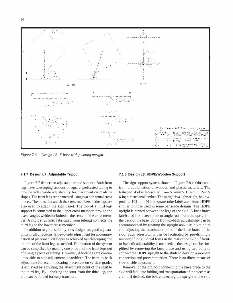
7.1.7 Design L7: Adjustable Tripod
Figure 7.7 depicts an adjustable tripod support. Both frontlegs have telescoping sections of square, perforated tubing toprovide side-to-side adjustability for placement on roadsideslopes. The front legs are connected using two horizontal crossbraces. The bolts that attach the cross members to the legs arealso used to attach the sign panel. The top of a third leg/support is connected to the upper cross member through theuse of angles welded or bolted to the center of the cross mem-ber. A short strut (also fabricated from tubing) connects thethird leg to the lower cross member.
In addition to good stability, this design has good adjusta-bility in all directions. Side-to-side adjustment for accommo-dation of placement on slopes is achieved by telescoping oneor both of the front legs as needed. Fabrication of the systemcan be simplified by making one or both of the front legs outof a single piece of tubing. However, if both legs are contin-uous, side-to-side adjustment is sacrificed. The front-to-backadjustment for accommodating placement on vertical gradesis achieved by adjusting the attachment point of the strut tothe third leg. By unbolting the strut from the third leg, theunit can be folded for easy transport.
50
7.1.8 Design L8: HDPE/Wooden Support
The sign support system shown in Figure 7.8 is fabricatedfrom a combination of wooden and plastic materials. The I-shaped skid is fabricated from 51-mm × 152-mm (2-in ×6-in) dimensional lumber. The upright is a lightweight, hollow-profile, 102-mm (4-in) square tube fabricated from HDPEsimilar to those used in some barricade designs. The HDPEupright is pinned between the legs of the skid. A knee bracefabricated from steel plate or angle runs from the upright tothe back of the base. Some front-to-back adjustability can beaccommodated by rotating the upright about its pivot pointand adjusting the attachment point of the knee brace to theskid. Such adjustability can be facilitated by pre-drilling anumber of longitudinal holes in the rear of the skid. If front-to-back tilt adjustability is not needed, the design can be sim-plified by removing the knee brace and using two bolts toconnect the HDPE upright to the skids to develop a momentconnection and prevent rotation. There is no direct means ofside-to-side adjustment.
Removal of the pin/bolt connecting the knee brace to theskid will facilitate folding and transportation of the system asa unit. If desired, the bolt connecting the upright to the skid
Figure 7.6. Design L6: X-base with pivoting upright.

51
Figure 7.7. Design L7: adjustable tripod.
Figure 7.8. Design L8: HDPE/wooden support.

can also be removed to separate the system into two parts tofacilitate transportation and/or repair.
This design is relatively inexpensive and easily constructedfrom readily available materials. However, Design L8 willlikely be less durable than the steel-frame designs, and han-dling will be more difficult because of increased weight. Aswith other single vertical-support designs, some flutter is likelyin high-wind conditions.
7.1.9 Design Summary
The least expensive system to construct is the HDPE/wooden system described as Design L8. However, this sys-tem will weigh more and may not be as durable as the steel-frame designs. The least expensive steel-frame design is theX-base system shown as Design L5. Both Design L5 andDesign L8 are single-support systems that may be suscepti-ble to flutter in windy conditions.
Design L1 is the next least expensive steel-frame design.The dual uprights are more cumbersome for on-site erection,but they provide more torsional stability of the sign panel toresist possible flutter. The tripod system, described herein asDesign L7, provides a reasonable compromise between econ-omy, stability, and adjustability. The incorporation of theadjustment plates into Design L3 (dual support) and DesignL6 (single support) increases the fabrication complexity andcost, but provides for adjustability of the sign panel in at leastone direction.
Impact performance of low-mounting-height sign supportsystems is generally enhanced by keeping the sign panelattached to the support members during the collision. There-fore, those sign support systems with connections to multi-ple uprights may perform better. These systems include De-signs L1, L3, L4, and L7. However, some contact of the signpanel with the windshield is expected in most cases, and thedegree and severity of the resulting windshield damage willdictate the performance assessment.
7.2 PRIORITIZATION
The design alternatives developed for low-mounting-heightsign supports with rigid sign substrates were reviewed and pri-oritized by the project panel. A weighted average was used toprioritize the designs for testing. Eight points were allocatedfor a first place vote, seven for second place, and so on. Thepoints allocated for each device by each panel member werethen summed to establish a ranking. The device with the great-est number of points is the device with the highest priority. Theweighted ranking analysis resulted in the following priority:
1. Design L7: adjustable tripod (51 points)2. Design L3: pivoting dual uprights (46 points)3. Design L1: independent dual uprights (40 points)4. Design L4: H-base with dual uprights (39 points)
52
5. Design L6: X-base with single pivoting upright (21 points)
6. Design L2: H-base with single upright (20 points)7. Design L8: wood base with HDPE upright (17 points)8. Design L5: X-base with single upright (13 points)
Some of the panel members who provided priorities for test-ing did not rank all eight designs. As a consequence, some ofthe designs did not receive points in the weighted rankinganalysis from all panel members.
Based on the input received, the top four designs wereclearly separated from the last four designs in the rankings.The top four designs are all dual-support alternatives, whilethe last four designs are all single-support systems. The lowerranking of the single-support systems reflects concern of thepanel members regarding their ability to function in windyconditions.
7.3 FULL-SCALE CRASH TESTING
All crash test and data analysis procedures used to evaluatethe low-mounting-height sign support systems were in accor-dance with the guidelines presented in NCHRP Report 350.Appendix C presents brief descriptions of these procedures.Additionally, the FHWA windshield damage classificationcriteria were followed in assessing damage to the windshield.
The tests followed the impact conditions of test designation3-71 of NCHRP Report 350. Test 3-71 involves an 820-kg(1808-lb) passenger car impacting the device at a speed of100 km/h (62 mi/h). This test is considered to be the criticalone for most work-zone devices because the propensity foroccupant compartment intrusion increases at higher speeds.A 50th-percentile male anthropomorphic dummy was placedin the driver’s position and restrained with standard equip-ment lap and shoulder belts, thus increasing the test inertialweight of the vehicle to approximately 900 kg (1984 lb).
Two separate sign support systems were offset approxi-mately 9 m (30 ft) from one another and placed at differentorientations with respect to the path of the vehicle. The firstsupport was oriented perpendicular to the vehicle path for ahead-on impact at 0 degree. The second support, placed be-hind the first sign support, was oriented parallel to the vehi-cle path for an end-on impact at 90 degrees. The supportswere placed on a paved concrete surface.
7.3.1 Test 5
Test Article
In accordance with the established priorities, the first low-mounting-height sign support tested was the adjustable tripodsystem (referred to previously as Design L7). Figure 7.9 pre-sents details for the variation of this support system that wastested. The two telescoping front legs were composed of a

Figure 7.9. Details of the adjustable tripod system used in Test 5.(continued on next page)

Figure 7.9. (Continued)

0.5-m (1-ft, 71⁄2-in) section of 38-mm (11⁄2-in) square, 12-gaugeperforated steel tubing inserted into the bottom of a 1.0-m(3-ft, 41⁄2-in) section of 44-mm (13⁄4-in) square, 12-gauge per-forated steel tubing. The front legs are connected togetherusing two horizontal cross braces fabricated from 44-mm(13⁄4-in) square, 12-gauge perforated steel tubing. The 8-mm(5⁄16-in) diameter, A325 or equivalent bolts that attach thecross members to the front legs are also used to attach the1.2-m × 1.2-m × 13-mm (4-ft × 4-ft × 1⁄2-in) plywood signpanel to the frame. The mounting height from the ground tothe bottom edge of the sign panel was 0.3 m (1 ft). The rearleg of the tripod-style frame is a 1.2-m (3-ft, 11-in) long sec-tion of 44-mm (13⁄4-in) square, 12-gauge perforated steel tub-ing. The top of the rear leg is connected to the upper crossmember through the use of a 44-mm (13⁄4-in) piece of 76-mm× 51-mm × 5-mm (3-in × 2-in × 3⁄16-in) steel angle welded tothe center of the cross member. A short strut (also fabricatedfrom 44-mm [13⁄4-in] square, 12-gauge perforated steel tubing)connects the rear leg to the lower cross member. An optionalcross bar was bolted to the bottom of the rear leg to providea means of ballasting the system. The single-bolt attachmentpermits the cross bar to rotate to accommodate placement ona cross slope. Two 18-kg (40-lb) sandbags were placed on thecross bar for the test.
55
One of the variables related to the tripod design that canaffect both impact performance and functionality is the tiltangle of the sign panel. A greater tilt angle will make the sys-tem less prone to rotate back into the windshield and will giveit more stability. However, as mentioned, the legibility of thesign may be compromised if the tilt angle becomes too large.For the crash test, the tilt angle of the sign panel was set at 30 degrees from vertical. This angle was chosen in consulta-tion with researchers who are recognized experts in signingand retro-reflectivity. The selected tilt angle should provide avisible, legible sign in both daytime and nighttime conditions.
Two tripod sign support systems were placed on a pavedconcrete surface in the path of the vehicle approximately 9 m(30 ft) apart from one another—one perpendicular to the pathof the vehicle and one parallel to the path of the vehicle.Photographs of the completed test installation are shown inFigure 7.10.
Test Vehicle
A 1998 Geo Metro, shown in Figure 7.11, was used forthe crash test. Test inertia weight of the vehicle was 820 kg(1808 lb), and its gross static weight was 897 kg (1978 lb).The height to the lower edge of the vehicle front bumper was
Figure 7.10. Adjustable tripod system used in Test 5. Figure 7.11. Vehicle before Test 5.

400 mm (15.7 in), and the height to the upper edge of thefront bumper was 525 mm (20.7 in). Additional dimensionsand information on the vehicle are given in Appendix D, Fig-ure D.5. The vehicle was directed into the installation usingthe cable reverse tow and guidance system and was releasedto be free-wheeling and unrestrained just before impact.
Impact Description
An 897-kg (1978-lb) vehicle, traveling at a speed of100.1 km/h (62.2 mi/h), impacted the first sign support head-on at 0 degree with the centerline of the sign support alignedwith the centerline of the vehicle. Shortly after contact, thelower corner of the sign panel deformed, and, at 0.010 s, thelegs began to deform. The sign panel began to separate fromthe frame at 0.015 s. The legs began to slide on the concretepavement at 0.018 s and, at 0.034 s, the tripod frame closedtogether and the rear leg contacted the bottom edge/corner ofthe sign panel. At 0.045 s, the lower fourth of the sign panelfractured; at 0.061 s, the top of the sign panel contacted thewindshield at the roofline; and at 0.083 s, the sign panel frac-tured across its centerline. At 0.095 s, the front of the vehi-cle lost contact with the legs of the first tripod while travelingat a speed of 94.9 km/h (59.0 mi/h). As the vehicle continuedforward, the legs lost contact with the hood at 0.112 s, andthe sign panel lost contact with the roof at 0.207 s. The legscontinued to travel in front of the vehicle and the right leg ofthe first tripod contacted the sign panel of the second easel at0.288 s. However, this contact did not appear to substantiallyalter the impact behavior of the second support.
At 0.234 s, the vehicle impacted the second sign supportend-on at 90 degrees with the centerline of the vehicle alignedwith the center of the tripod. Speed of the vehicle at time ofcontact was 94.4 km/h (58.7 mi/h). Shortly after impact withthe second sign support, the support began to slide on theconcrete pavement. At 0.398 s, the support began to rotatecounterclockwise. At 0.601 s, the vehicle traveled out of viewof the perpendicular camera while traveling at a speed of84.1 km/h (52.3 mi/h).
Brakes on the vehicle were applied at 1.9 s. The vehiclecame to rest 82.9 m (272.0 ft) downstream of impact and4.3 m (14.0 ft) to the left of centerline. Sequential photographsof the test period are shown in Appendix E, Figure E.5.
Test Results
Both sign supports readily activated at impact by yieldingand fracturing. The debris was scattered over an area 74.2 m(243.5 ft) long and 14.3 m (47.0 ft) to the left of the initialimpact point.
The vehicle remained upright during and after the collisionevent. Damage to the vehicle is shown in Figure 7.12. Thefront bumper, left headlight, hood, and roof were deformed.Maximum crush to the exterior of the vehicle was 30 mm(1.2 inches) at the left front at bumper height. The windshield
56
was cracked on the right side over an area 75 mm × 20 mm(3.0 in × 0.8 in) wide, but remained intact and was not de-formed inward (FHWA windshield damage classificationCase 5). The roof sustained only scuff marks. There was noother measurable occupant compartment deformation.
In the longitudinal direction, occupant impact velocity was2.6 m/s (8.5 ft/s) at 0.440 s, the highest 0.010-s occupant ride-down acceleration was −1.0 g from 0.496 s to 0.506 s, and themaximum 0.050-s average acceleration was −2.0 g’s be-tween 0.377 s and 0.427 s. In the lateral direction, the occu-pant impact velocity was 0.1 m/s (0.3 ft/s) at 0.440 s, thehighest 0.010-s occupant ridedown acceleration was −1.3 g’sfrom 0.494 s to 0.504 s, and the maximum 0.050-s averagewas −0.7 g’s between 0.489 s and 0.539 s. The test results aresummarized in Figure 7.13. Vehicle angular displacementsand accelerations versus time traces are presented in Appen-dix F, Figures F.29 through F.35.
As summarized in Table 7.1, the perforated steel-tube, tri-pod sign support system with 1.2-m × 1.2-m × 13-mm (4-ft× 4-ft × 1⁄2-in) plywood sign panel mounted 0.3 m (1 ft) aboveground met all required evaluation criteria of NCHRP Report350 for both the head-on and end-on impact scenarios. Theimpact performance of the sign support system is, therefore,considered acceptable.
Figure 7.12. Vehicle after Test 5.

0.000 s 0.139 s 0.368 s 0.516 s
General Information Test Agency............................... Test No. .................................... Date ........................................... Test Article Type........................................... Name ......................................... Installation Height, m (ft)............ Material or Key Elements .......... Soil Type and Condition............. Test Vehicle Type........................................... Designation................................ Model ......................................... Mass, kg Curb........................................ Test Inertial............................. Dummy ................................... Gross Static............................
Texas Transportation Institute 474010-5 10-07-2004 Low-Mounting-Height Sign Support Adjustable Tripod System 0.3 (1.0) to Bottom of Sign Panel Three telescoping, perforated steel-tube legs with plywood sign Pavement, Dry Production 820C 1998 Geo Metro 805 820 77 897
Impact Conditions Angle, deg ................................. Speed, km/h (mi/h) @ 0 deg ..... Speed, km/h (mi/h) @ 90 deg ... Exit Conditions Speed, km/h (mi/h) .................... Occupant Risk Values Impact Velocity, m/s (ft/s) Longitudinal ............................ Lateral .................................... THIV, km/h................................. Ridedown Accelerations, g’s Longitudinal ............................ Lateral .................................... PHD, g’s .................................... ASI ............................................ Max. 0.050-s Average, g’s Longitudinal ............................ Lateral .................................... Vertical ...................................
0 & 90 100.1 (62.2)94.4 (58.7) 84.1 (52.3) 2.6 (8.5) 0.1 (0.3) 9.5 -1.0 -1.3 1.5 0.17 -2.0 -0.7 0.7
Test Article Debris Pattern Length, m (ft).................................... Width, m (ft) Left................................................ Right ............................................Vehicle Damage Exterior VDS .............................................. CDC.............................................. Max. Exterior Vehicle Crush, mm (in) .............. Interior OCDI............................................. Max. Occupant Compartment Deformation, mm (in).................Post-Impact Behavior (during 1.0 sec after impact) Max. Yaw Angle, deg.................... Max. Pitch Angle, deg................... Max. Roll Angle, deg ....................
74.2 (243.5) 14.3 (47.0) 0 12FD1 12FDEN1 30 (1.2 in) FS0000000 0 -7 2 4
Figure 7.13. Summary of results for Test 5.

Discussion
The telescoping front legs of this sign support system pro-vide side-to-side adjustability to accommodate placement ofthe sign stand on roadside slopes. Fabrication of the systemcan be simplified by making one or both of the front legs outof a single piece of tubing. However, if both legs are fabri-cated in this manner, side-to-side adjustment is sacrificed.The front-to-back adjustment for accommodating placementon vertical grades is achieved by adjusting the attachmentpoint of the strut to the third leg.
If it is desired to help ensure the tripod is installed in thefield with a tilt angle at or near the tested angle of 30 degrees,the rear support leg can be fabricated from thin-wall steeltubing that is non-perforated, and the hole for attachment ofthe strut can be drilled at the proper location. Use of a singleattachment hole would help emphasize the importance ofinstalling the sign at the proper angle. Additional holes canbe drilled into the support leg if a range of angles is consid-
58
ered acceptable and some degree of front-to-back adjustmentis desired.
The unit can be folded for easy transport by unbolting thestrut from the third leg. The assembly and disassembly canbe further enhanced by using a pin rather than a bolt to attachthe strut to the rear leg.
The cross bar at the bottom of the rear leg is consideredoptional and can be used when placement of ballast is desiredfor additional stability. The tested condition, which incorpo-rated the cross bar and ballast, is believed to represent a worstcase condition. The ballast provides additional resistance tosliding, which can increase the resulting rotational velocityof the sign stand. Since the tested configuration performedwell, the system should perform equally well without the crossbar and ballast.
The steel angles can optionally be attached to the perforatedsteel-tube cross members using an 8-mm (5⁄16-in) diameter,A325 or equivalent bolt. Such attachment would, if desired,eliminate the need for any welded fabrication in the system.
TABLE 7.1 Performance evaluation summary for Test 5Test Agency: Texas Transportation Institute Test No.: 474010-5 Test Date: 10/07/2004
NCHRP Report 350 Evaluation Criteria Test Results Assessment Structural Adequacy B. The test article should readily activate in a
predictable manner by breaking away, fracturing, or yielding.
Both easels readily activated as designed by yielding and fracturing.
Pass
Occupant Risk D. Detached elements, fragments, or other debris
from the test article should not penetrate or show potential for penetrating the occupant compartment, or present an undue hazard to other traffic, pedestrians, or personnel in a work zone. Deformations of, or intrusions into, the occupant compartment that could cause serious injuries should not be permitted.
Debris was scattered along the vehicle path and did not show potential for hazard. The windshield was cracked on the right side but remained intact and was not deformed inward (FHWA Case 5). The left side of the windshield sustained only scuff marks. There was no measurable occupant compartment deformation.
Pass
E. Detached elements, fragments, or other debris from the test article, or vehicular damage should not block the driverʼs vision or otherwise cause the driver to lose control of the vehicle.
The driverʼs vision was not blocked. Pass
F. The vehicle should remain upright during and after collision although moderate roll, pitching, and yawing are acceptable.
The vehicle remained upright throughout and after the crash period.
Pass
H. Occupant impact velocities should satisfy the following:
Occupant Velocity Limits (m/s)
Longitudinal occupant impact velocity was 2.6 m/s (8.5 ft/s).
Pass
Component Preferred Maximum Longitudinal 3 5
I. Occupant ridedown accelerations should satisfy the following:
Occupant Ridedown Acceleration Limits (gʼs) Component Preferred Maximum Longitudinal and
lateral 15 20
Longitudinal ridedown acceleration was -1.0 gʼs, and lateral ridedown acceleration -1.3 gʼs.
Pass
Vehicle Trajectory K. After collision, it is preferable that the
vehicleʼs trajectory not intrude into adjacent traffic lanes.
The vehicle continued on a straightforward path all along the trajectory path and did not intrude into adjacent lanes.
Pass*
N. Vehicle trajectory behind the test article is acceptable.
The vehicle came to rest behind the test articles.
Pass
*Criterion K preferable, not required.

7.3.2 Test 6
Test Article
Following the priorities established by the project panel, thesecond low-mounting-height sign support system crash testedwas Design L3, which incorporates pivoting dual uprights.Details of the tested system are shown in Figure 7.14. The twouprights are 1.1 m (3 ft, 7 in) long and are fabricated from38-mm (11⁄2-in) square, 12-gauge perforated steel tubing. A1.2-m × 1.2-m × 13-mm (4-ft × 4-ft × 1⁄2-in) plywood signpanel is bolted to the uprights using two 8-mm (5⁄16-in) diam-eter, A325 or equivalent bolts. The uprights telescope inside0.3-m (1-ft) sleeves fabricated from 44-mm (13⁄4-in) square,12-gauge perforated steel tubing such that the bottom edgeof the sign panel is 0.3 m (1 ft) above ground. The uprightsare secured inside the sleeves using an 8-mm (5⁄16-in) diame-ter, A325 or equivalent bolt. Each sleeve is bolted to a 5-mm(3⁄16-in) thick, steel pivot plate, which in turn is bolted to thecenter of a 1.2-m (4-ft) long skid fabricated from 44-mm(13⁄4-in) square, 12-gauge perforated steel tubing using three8-mm (5⁄16-in) diameter, A325 or equivalent bolts. The sleevesare bolted to the pivot plates in two locations using 8-mm(5⁄16-in) diameter, A325 or equivalent bolts. A bolt throughthe center of the pivot plates serves as a point of rotation forthe sign panel assembly. A second bolt near the top edge of thepivot plate secures the upright at the desired angle and pro-vides moment resistance to accommodate service loads. Inthe crash test, the sign panel and uprights were oriented per-pendicular to the skids as shown in Figure 7.14.
Two identical sign support systems were placed on a pavedconcrete surface in the path of the vehicle approximately 9 m(30 ft) apart from one another—one perpendicular to the pathof the vehicle and one parallel to the path of the vehicle. Eachsystem was ballasted with four 18-kg (40-lb) sandbags. Photo-graphs of the completed test installation are shown in Fig-ure 7.15.
Test Vehicle
A 1998 Geo Metro, shown in Figure 7.16, was used forthe crash test. Test inertia weight of the vehicle was 820 kg(1808 lb), and its gross static weight was 897 kg (1978 lb).The height to the lower edge of the vehicle front bumper was400 mm (15.7 in), and the height to the upper edge of thefront bumper was 525 mm (20.7 in). Additional dimensionsand information on the vehicle are given in Appendix D, Fig-ure D.6. The vehicle was directed into the installation usingthe cable reverse tow and guidance system and was releasedto be free-wheeling and unrestrained just before impact.
Impact Description
The 897-kg (1978-lb) vehicle, traveling at a speed of 99.8 km/h (62.0 mi/h), impacted the first sign support at
59
0 degree with the centerline of the vehicle aligned with thecenterline of the sign. Shortly after impact, the legs began todeform to the bumper, and, at 0.007 s, the sign panel frac-tured at the lower corner on the right side and separated fromthe right leg at the lower connection point. At 0.017 s, the leftleg fractured at bumper height, and, at 0.020 s, the right legfractured at bumper height. The left leg lost contact with thevehicle at 0.046 s, and the top of the sign panel contacted thewindshield at roofline at 0.049 s. At 0.054 s, the right leg lostcontact with the vehicle while the vehicle was traveling at aspeed of 95.3 km/h (59.2 mi/h). The sign panel lay across thewindshield from 0.076 s to 0.119 s. By 0.305 s, the sign panelwas completely clear of the windshield and was sliding acrossthe roof.
At 0.368 s, the vehicle contacted the second temporary signsupport end-on at 90 degrees with the centerline of the vehi-cle aligned with the sign panel. The speed of the vehicle attime of impact was 90.4 km/h (56.2 mi/h). As the vehicle con-tinued forward, the leg and skid on the impact side of the signsupport folded under the vehicle and the sign panel was car-ried along in front of the vehicle. The vehicle lost contactwith the first sign panel at 0.466 s (sign panel slid off theroof), and the vehicle lost contact with the second sign panelat 0.560 s. At loss of contact with the second panel, the vehi-cle was traveling at a speed of 76.8 km/h (47.7 mi/h).
Brakes on the vehicle were applied at 1.9 s. The vehiclecame to rest 83.5 m (274.0 ft) downstream of impact and6.1 m (20.0 ft) to the right of centerline. Sequential photo-graphs of the test period are shown in Appendix E, Figure E.6.
Test Results
Both sign supports readily activated at impact by yieldingand fracturing. The debris was scattered over an area 86.9 m(285.0 ft) long and 11.7 m (38.5 ft) to the left of the initialimpact point.
The vehicle remained upright during and after the colli-sion event. Damage sustained by the vehicle is shown inFigure 7.17. The front bumper, hood, radiator, and roof weredeformed and the right front tire was deflated. Maximumcrush to the exterior of the vehicle was 180 mm (7.1 in) atthe center front at bumper height. The windshield was shat-tered and deformed inward 60 mm (2.3 in). The FHWA wind-shield damage classification was a combination of Case 5and Case 6. There were no holes or tears in the windshield,nor was the windshield separated from its frame. There wasno other measurable occupant compartment deformation.
In the longitudinal direction, the occupant impact velocitywas 2.4 m/s (7.9 ft/s) at 0.382 s, the highest 0.010-s occupantridedown acceleration was −4.5 g’s from 0.411 s to 0.421 s,and the maximum 0.050-s average acceleration was −2.8 g’sbetween 0.372 and 0.422 s. In the lateral direction, the occu-pant impact velocity was 0.2 m/s (0.7 ft/s) at 0.382 s, thehighest 0.010-s occupant ridedown acceleration was 1.3 g’sfrom 0.430 s to 0.440 s, and the maximum 0.050-s average

Figure 7.14. Details of the pivoting dual-upright system used in Test 6.
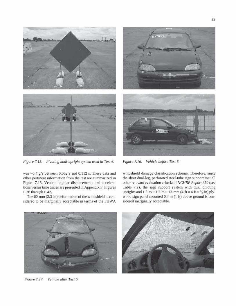
was −0.4 g’s between 0.062 s and 0.112 s. These data andother pertinent information from the test are summarized inFigure 7.18. Vehicle angular displacements and accelera-tions versus time traces are presented in Appendix F, FiguresF.36 through F.42.
The 60-mm (2.3-in) deformation of the windshield is con-sidered to be marginally acceptable in terms of the FHWA
61
windshield damage classification scheme. Therefore, sincethe short dual-leg, perforated steel-tube sign support met allother relevant evaluation criteria of NCHRP Report 350 (seeTable 7.2), the sign support system with dual pivotinguprights and 1.2-m × 1.2-m × 13-mm (4-ft × 4-ft × 1⁄2-in) ply-wood sign panel mounted 0.3 m (1 ft) above ground is con-sidered marginally acceptable.
Figure 7.15. Pivoting dual-upright system used in Test 6. Figure 7.16. Vehicle before Test 6.
Figure 7.17. Vehicle after Test 6.
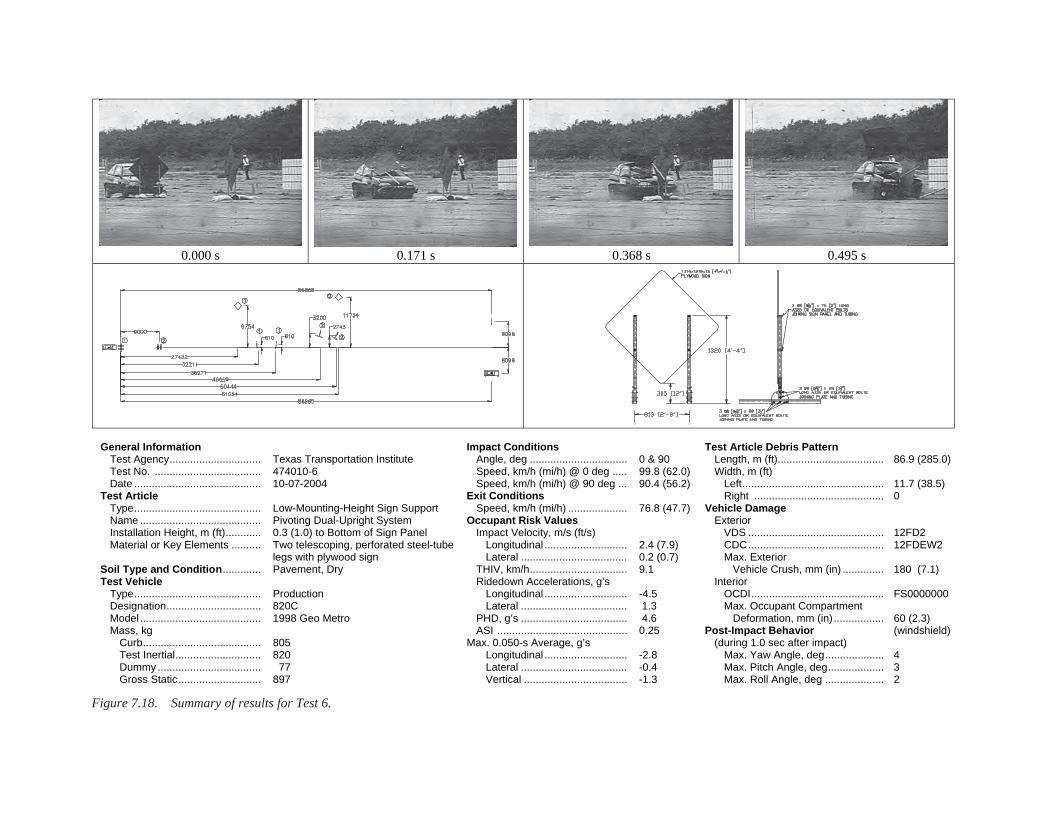
0.000 s 0.171 s 0.368 s 0.495 s
General Information Test Agency............................... Test No. .................................... Date ........................................... Test Article Type........................................... Name ......................................... Installation Height, m (ft)............ Material or Key Elements .......... Soil Type and Condition............. Test Vehicle Type........................................... Designation................................ Model ......................................... Mass, kg Curb........................................ Test Inertial............................. Dummy ................................... Gross Static............................
Texas Transportation Institute 474010-6 10-07-2004 Low-Mounting-Height Sign Support Pivoting Dual-Upright System 0.3 (1.0) to Bottom of Sign Panel Two telescoping, perforated steel-tube legs with plywood sign Pavement, Dry Production 820C 1998 Geo Metro 805 820 77 897
Impact Conditions Angle, deg ................................. Speed, km/h (mi/h) @ 0 deg ..... Speed, km/h (mi/h) @ 90 deg ... Exit Conditions Speed, km/h (mi/h) .................... Occupant Risk Values Impact Velocity, m/s (ft/s) Longitudinal ............................ Lateral .................................... THIV, km/h................................. Ridedown Accelerations, g’s Longitudinal ............................ Lateral .................................... PHD, g’s .................................... ASI ............................................ Max. 0.050-s Average, g’s Longitudinal ............................ Lateral .................................... Vertical ...................................
0 & 90 99.8 (62.0) 90.4 (56.2) 76.8 (47.7) 2.4 (7.9) 0.2 (0.7) 9.1 -4.5 1.3 4.6 0.25 -2.8 -0.4 -1.3
Test Article Debris Pattern Length, m (ft).................................... Width, m (ft) Left................................................ Right ............................................Vehicle Damage Exterior VDS .............................................. CDC.............................................. Max. Exterior Vehicle Crush, mm (in) .............. Interior OCDI............................................. Max. Occupant Compartment Deformation, mm (in).................Post-Impact Behavior (during 1.0 sec after impact) Max. Yaw Angle, deg.................... Max. Pitch Angle, deg................... Max. Roll Angle, deg ....................
86.9 (285.0) 11.7 (38.5) 0 12FD2 12FDEW2 180 (7.1) FS0000000 60 (2.3) (windshield) 4 3 2
Figure 7.18. Summary of results for Test 6.

Discussion
Side-to-side adjustment of the sign support system toaccommodate placement of the sign stand on roadsideslopes is achieved by telescoping one of the uprights insideits sleeve or adjusting the attachment of one of the uprightsto the sign panel. To tilt the sign panel to the front or backto accommodate placement on vertical grade, the upperadjustment bolt/pin used to connect the sleeve to the pivotplate is removed and reinserted after aligning the sleeve withone of the other holes in the plate.
The unit can be easily folded for transport as a single unitby removing the top adjusting bolt and laying the sign down.The assembly and disassembly can be further enhanced byusing a pin rather than a bolt at this upper connection pointon the pivot plate. If desired (e.g., for ease of repair), the signpanel and uprights can be readily detached from the base byremoving both bolts from the sleeves.
63
If front-to-back adjustment is neither needed nor desired,fabrication of the pivot plate can be simplified by using onlytwo holes—one in the center of the plate and one at the topedge. A two-hole pivot plate eliminates the angle adjustmentof the uprights, but retains the ability to readily fold the sys-tem down for transport. The absence of the additional holesin the pivot plate will not affect the impact performance ofthe system. If desired, the pivot plates can be welded ratherthan bolted to the skids. This alternative fabrication methodshould not adversely affect impact performance.
7.3.3 Test 7
Test Article
The final low-mounting-height sign support system crashtested was Design L1. Details of the tested system are shownin Figure 7.19. The design uses two 1.1-m (3-ft, 7-in) long
TABLE 7.2 Performance evaluation summary for Test 6Test Agency: Texas Transportation Institute Test No.: 474010-6 Test Date: 10/07/2004
NCHRP Report 350 Evaluation Criteria Test Results Assessment Structural Adequacy B. The test article should readily activate in a
predictable manner by breaking away, fracturing, or yielding.
Both short, dual-leg sign supports readily activated as designed by yielding and fracturing.
Pass
Occupant Risk D. Detached elements, fragments, or other debris
from the test article should not penetrate or show potential for penetrating the occupant compartment, or present an undue hazard to other traffic, pedestrians, or personnel in a work zone. Deformations of, or intrusions into, the occupant compartment that could cause serious injuries should not be permitted.
Debris remained along the vehicle path. The windshield was shattered and deformed inward 60 mm (2.3 in) (FHWA Case 5 and 6). There were no holes or tears in the windshield, nor was the windshield separated from its frame. There was no other measurable occupant compartment deformation.
Marginal
E. Detached elements, fragments, or other debris from the test article, or vehicular damage should not block the driverʼs vision or otherwise cause the driver to lose control of the vehicle.
The sign panel completely covered the windshield from 0.076 s to 0.119 s; however, this was for only 0.043 s.
Pass
F. The vehicle should remain upright during and after collision although moderate roll, pitching, and yawing are acceptable.
The vehicle remained upright throughout and after the crash period.
Pass
H. Occupant impact velocities should satisfy the following:
Occupant Velocity Limits (m/s)
Longitudinal occupant impact velocity was 2.4 m/s (7.9 ft/s).
Pass
Component Preferred Maximum Longitudinal 3 5
I. Occupant ridedown accelerations should satisfy the following:
Occupant Ridedown Acceleration Limits (gʼs) Component Preferred Maximum Longitudinal and
lateral 15 20
Longitudinal ridedown acceleration was -4.5 gʼs, and lateral ridedown acceleration was 1.3 gʼs.
Pass
Vehicle Trajectory K. After collision, it is preferable that the
vehicleʼs trajectory not intrude into adjacent traffic lanes.
The vehicle continued on a straightforward path all along the trajectory path, and did not intrude into adjacent lanes.
Pass*
N. Vehicle trajectory behind the test article is acceptable.
The vehicle came to rest behind the test articles.
Pass
*Criterion K preferable, not required.
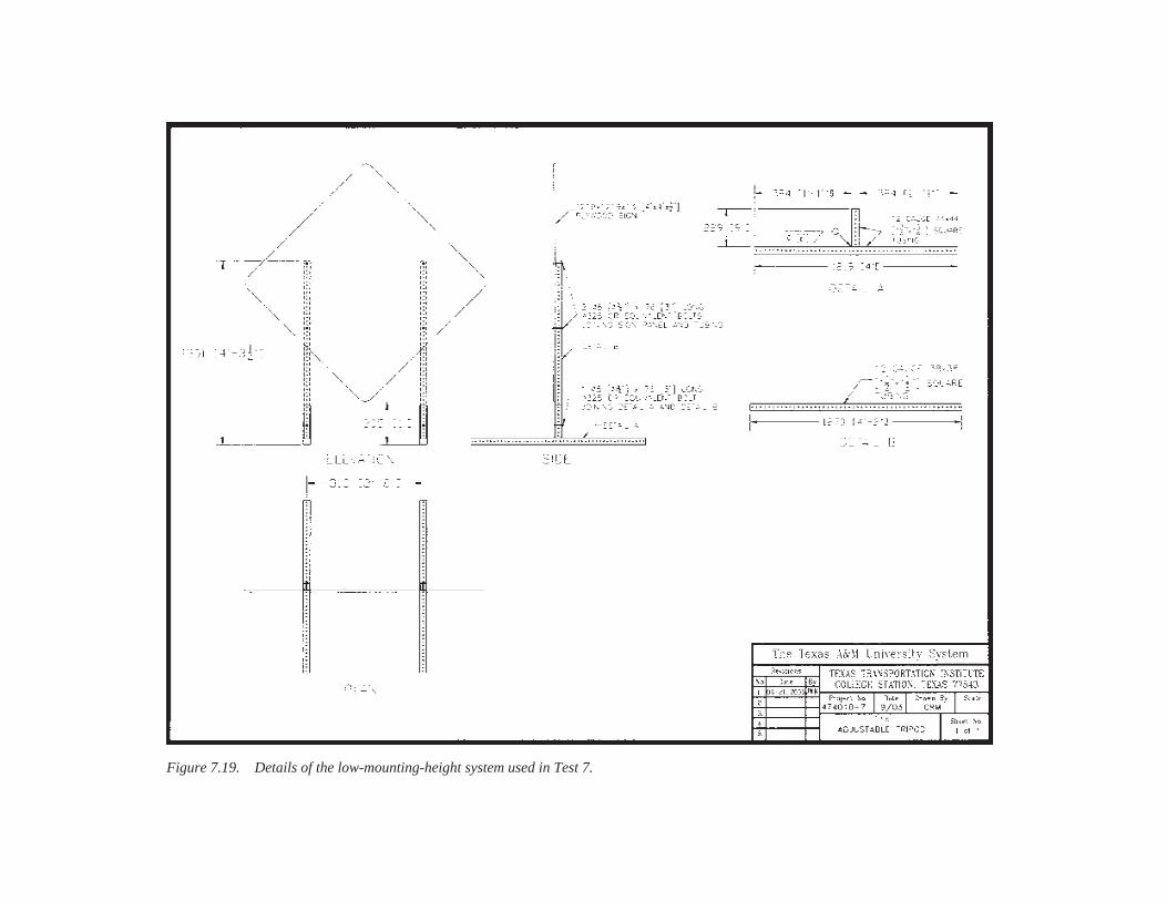
Figure 7.19. Details of the low-mounting-height system used in Test 7.
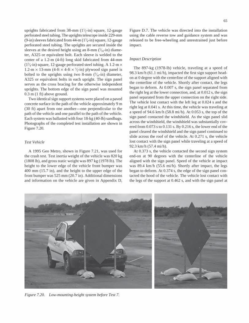
uprights fabricated from 38-mm (11⁄2-in) square, 12-gaugeperforated steel tubing. The uprights telescope inside 229-mm(9-in) sleeves fabricated from 44-m (13⁄4-in) square, 12-gaugeperforated steel tubing. The uprights are secured inside thesleeves at the desired height using an 8-mm (5⁄16-in) diame-ter, A325 or equivalent bolt. Each sleeve is welded to thecenter of a 1.2-m (4-ft) long skid fabricated from 44-mm(13⁄4-in) square, 12-gauge perforated steel tubing. A 1.2-m ×1.2-m × 13-mm (4-ft × 4-ft × 1⁄2-in) plywood sign panel isbolted to the uprights using two 8-mm (5⁄16-in) diameter,A325 or equivalent bolts in each upright. The sign panelserves as the cross bracing for the otherwise independentuprights. The bottom edge of the sign panel was mounted0.3 m (1 ft) above ground.
Two identical sign support systems were placed on a pavedconcrete surface in the path of the vehicle approximately 9 m(30 ft) apart from one another—one perpendicular to thepath of the vehicle and one parallel to the path of the vehicle.Each system was ballasted with four 18-kg (40-lb) sandbags.Photographs of the completed test installation are shown inFigure 7.20.
Test Vehicle
A 1995 Geo Metro, shown in Figure 7.21, was used forthe crash test. Test inertia weight of the vehicle was 820 kg(1808 lb), and gross static weight was 897 kg (1978 lb). Theheight to the lower edge of the vehicle front bumper was400 mm (15.7 in), and the height to the upper edge of thefront bumper was 525 mm (20.7 in). Additional dimensionsand information on the vehicle are given in Appendix D,
65
Figure D.7. The vehicle was directed into the installationusing the cable reverse tow and guidance system and wasreleased to be free-wheeling and unrestrained just beforeimpact.
Impact Description
The 897-kg (1978-lb) vehicle, traveling at a speed of98.3 km/h (61.1 mi/h), impacted the first sign support head-on at 0 degree with the centerline of the support aligned withthe centerline of the vehicle. Shortly after contact, the legsbegan to deform. At 0.007 s, the sign panel separated fromthe right leg at the lower connection, and, at 0.012 s, the signpanel separated from the upper connection on the right side.The vehicle lost contact with the left leg at 0.024 s and theright leg at 0.041 s. At this time, the vehicle was traveling ata speed of 94.6 km/h (58.8 mi/h). At 0.053 s, the top of thesign panel contacted the windshield. As the sign panel slidacross the windshield, the windshield was substantially cov-ered from 0.073 s to 0.131 s. By 0.216 s, the lower end of thepanel cleared the windshield and the sign panel continued toslide across the roof of the vehicle. At 0.271 s, the vehiclelost contact with the sign panel while traveling at a speed of92.3 km/h (57.4 mi/h).
At 0.373 s, the vehicle contacted the second sign systemend-on at 90 degrees with the centerline of the vehiclealigned with the sign panel. Speed of the vehicle at impactwas 89.4 km/h (55.6 mi/h). Shortly after impact, the legsbegan to deform. At 0.374 s, the edge of the sign panel con-tacted the hood of the vehicle. The vehicle lost contact withthe legs of the support at 0.462 s, and with the sign panel at
Figure 7.20. Low-mounting-height system before Test 7.

0.455 s. At this time, the vehicle was traveling at a speed of76.4 km/h (47.5 mi/h).
Brakes on the vehicle were applied at 1.9 s. The vehiclecame to rest 78.3 m (257.0 ft) downstream of impact and0.3 m (1.0 ft) to the right of centerline. Sequential photo-graphs of the test period are shown in Appendix E, Figure E.7.
Test Results
Both sign supports readily activated at impact by yield-ing and fracturing. The debris was scattered over an area60.9 m (200.0 ft) long and 12.0 m (39.4 ft) to the right and1.7 m (5.5 ft) to the left of the initial impact point.
The vehicle remained upright during and after the colli-sion event. Damage to the vehicle is shown in Figure 7.22.The front bumper, hood, and roof were deformed. Maxi-mum crush to the exterior of the vehicle was 90 mm (3.5in) at the center front at bumper height. The windshieldwas shattered and deformed inward 35 mm (1.4 in). TheFHWA windshield damage classification was a combina-tion of Case 5 and Case 6. There were no holes or tears inthe windshield, nor was the windshield separated from its
66
frame. There was no other measurable occupant compart-ment deformation.
In the longitudinal direction, the occupant impact veloc-ity was 2.3 m/s (7.5 ft/s) at 0.319 s, the highest 0.010-s occu-pant ridedown acceleration was −5.6 g’s from 0.443 s to0.453 s, and the maximum 0.050-s average acceleration was−3.4 g’s between 0.408 s and 0.458 s. In the lateral direction,the occupant impact velocity was 0.0 m/s (0.0 ft/s) at 0.319 s,the highest 0.010-s occupant ridedown acceleration was −1.2 g’s from 0.430 s to 0.440 s, and the maximum 0.050-saverage was 0.5 g’s between 0.448 s and 0.498 s. These dataand other pertinent information from the test are summa-rized in Figure 7.23. Vehicle angular displacements andaccelerations versus time traces are presented in AppendixF, Figures F.43 through F.49.
As summarized in Table 7.3, the sign support system withindependent perforated steel-tube uprights and 1.2-m × 1.2-m× 13-mm (4-ft × 4-ft × 1⁄2-in) plywood sign panel mounted at0.3 m (1 ft) above ground met all required evaluation criteriaof NCHRP Report 350 for both the head-on and end-on im-pact scenarios. The impact performance of the sign supportsystem is, therefore, considered acceptable.
Figure 7.22. Vehicle after Test 7.Figure 7.21. Vehicle before Test 7.
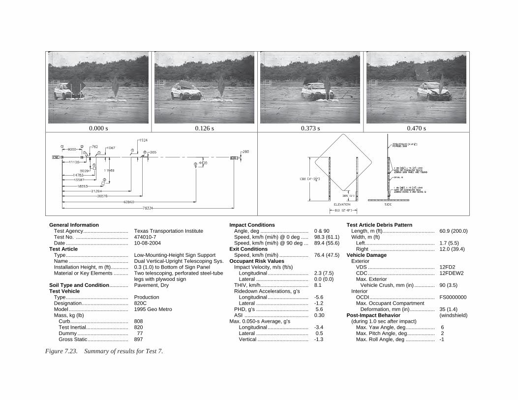
0.000 s 0.126 s 0.373 s 0.470 s
General Information Test Agency............................... Test No. .................................... Date ........................................... Test Article Type........................................... Name ......................................... Installation Height, m (ft)............ Material or Key Elements .......... Soil Type and Condition............. Test Vehicle Type........................................... Designation................................ Model ......................................... Mass, kg (lb) Curb........................................ Test Inertial............................. Dummy ................................... Gross Static............................
Texas Transportation Institute 474010-7 10-08-2004 Low-Mounting-Height Sign Support Dual Vertical-Upright Telescoping Sys.0.3 (1.0) to Bottom of Sign Panel Two telescoping, perforated steel-tube legs with plywood sign Pavement, Dry Production 820C 1995 Geo Metro 808 820 77 897
Impact Conditions Angle, deg ................................. Speed, km/h (mi/h) @ 0 deg ..... Speed, km/h (mi/h) @ 90 deg ... Exit Conditions Speed, km/h (mi/h) .................... Occupant Risk Values Impact Velocity, m/s (ft/s) Longitudinal ............................ Lateral .................................... THIV, km/h................................. Ridedown Accelerations, g’s Longitudinal ............................ Lateral .................................... PHD, g’s .................................... ASI ............................................ Max. 0.050-s Average, g’s Longitudinal ............................ Lateral .................................... Vertical ...................................
0 & 90 98.3 (61.1) 89.4 (55.6) 76.4 (47.5) 2.3 (7.5) 0.0 (0.0) 8.1 -5.6 -1.2 5.6 0.30 -3.4 0.5 -1.3
Test Article Debris Pattern Length, m (ft).................................... Width, m (ft) Left................................................ Right ............................................Vehicle Damage Exterior VDS .............................................. CDC.............................................. Max. Exterior Vehicle Crush, mm (in) .............. Interior OCDI............................................. Max. Occupant Compartment Deformation, mm (in).................Post-Impact Behavior (during 1.0 sec after impact) Max. Yaw Angle, deg.................... Max. Pitch Angle, deg................... Max. Roll Angle, deg ....................
60.9 (200.0)
12.0 (39.4) 1.7 (5.5)
12FD2 12FDEW2 90 (3.5) FS0000000 35 (1.4) (windshield) 6 2 -1
Figure 7.23. Summary of results for Test 7.

Discussion
Design L1 was designed to be a very inexpensive andsimple-to-construct system. It is the simplest, most inex-pensive design from among those considered under the proj-ect. As such, the functionality may not be as high as forsome of the other designs. However, enhanced adjustabil-ity tends to increase the cost and complexity of a system.Placement of the sign support on a roadside slope can be
68
accommodated by adjusting the height of the downhillupright by extending it out of the sleeve. Transportation anderection is facilitated by the removal of bolts connecting theuprights to the skids.
In the opinion of the researchers, the additional of a hori-zontal cross brace for added stability should not adverselyaffect the impact performance of this low-mounting-heightsign support system if the cross brace is placed across thesleeves at or near the skids.
TABLE 7.3 Performance evaluation summary for Test 7Test Agency: Texas Transportation Institute Test No.: 474010-7 Test Date: 10/08/2004
NCHRP Report 350 Evaluation Criteria Test Results Assessment Structural Adequacy B. The test article should readily activate in a
predictable manner by breaking away, fracturing, or yielding.
Both short, dual-leg sign supports readily activated as designed by yielding and fracturing.
Pass
Occupant Risk D. Detached elements, fragments, or other debris
from the test article should not penetrate or show potential for penetrating the occupant compartment, or present an undue hazard to other traffic, pedestrians, or personnel in a work zone. Deformations of, or intrusions into, the occupant compartment that could cause serious injuries should not be permitted.
Debris remained along the vehicle path. The windshield was shattered and deformed inward 35 mm (1.4 in) (FHWA Case 5 and 6). There were no holes or tears in the windshield, nor was the windshield separated from its frame. There was no other measurable occupant compartment deformation.
Pass
E. Detached elements, fragments, or other debris from the test article, or vehicular damage should not block the driverʼs vision or otherwise cause the driver to lose control of the vehicle.
The windshield was covered briefly from 0.073 s until 0.131 s; however, this was only for 0.058 s.
Pass
F. The vehicle should remain upright during and after collision although moderate roll, pitching, and yawing are acceptable.
The vehicle remained upright throughout and after the crash period.
Pass
H. Occupant impact velocities should satisfy the following:
Occupant Velocity Limits (m/s) Component Preferred Maximum Longitudinal 3 5
Longitudinal occupant impact velocity was 2.3 m/s (7.5 ft/s).
Pass
I. Occupant ridedown accelerations should satisfy the following:
Occupant Ridedown Acceleration Limits (gʼs) Component Preferred Maximum Longitudinal and
lateral 15 20
Longitudinal ridedown acceleration was -5.6 gʼs, and lateral ridedown acceleration was -1.2 gʼs.
Pass
Vehicle Trajectory K. After collision, it is preferable that the
vehicleʼs trajectory not intrude into adjacent traffic lanes.
The vehicle continued on a straightforward path all along the trajectory path and did not intrude into adjacent lanes.
Pass*
N. Vehicle trajectory behind the test article is acceptable.
The vehicle came to rest behind the test articles.
Pass
*Criterion K preferable, not required.

69
CHAPTER 8
HIGH-MOUNTING-HEIGHT SIGN SUPPORTS WITH RIGID SIGN SUBSTRATES
The final set of work-zone traffic control devices selectedby the project panel for development under Phase II of theproject was a high-mounting-height, generic sign support sys-tem with rigid sign substrate that can be fabricated from in-expensive, readily available materials. For purposes of thisproject, high-mounting-height systems were defined as thosewith a mounting height from 1.5 m to 2.1 m (5 ft to 7 ft).
Many of the acceptable proprietary alternatives availablefor this set are single-support sign stands that are used in com-bination with a roll-up–type fabric or vinyl sign panel. The useof a fabric/vinyl sign substrate reduces the weight of the unitand enables it to shed some wind, thereby, reducing the windload requirements on the support and the amount of ballastrequired to resist overturn. Although some of these systemscan offer advantages such as portability, ease of erection, andadjustable mounting height, more rigid sign substrates aresometimes preferred by user agencies because of their lowercost, availability, and stiffness. Whereas the legibility and retro-reflectivity of vinyl roll-up signs may be reduced in windyconditions due to their propensity to lean and deflect (some-times by design), more rigid sign panels can better retaintheir shape and orientation in windy conditions if adequatestructural support is provided.
However, while some of the characteristics of a rigid sub-strate may be desirable from a cost or functional standpoint,their rigidity and mass make them more critical than othersubstrate materials from a crashworthiness standpoint. High-mounting-height, portable sign supports with rigid aluminumor plywood substrates have been problematic in terms ofimpact performance. If the supports do not release or fracturereadily upon impact, they may deform around the front of theimpacting vehicle and carry either the sign panel and/or topof the supports into the windshield and roof of the vehicle. Inparticular, impacts with high-mounting-height sign supportsoriented 90 degrees to the travel path of the vehicle havecaused the rigid substrate to penetrate the windshield and/orthe roof sheet metal.
Successful crash tests usually involve the early release ofthe sign panel or fracture of the support mast at or near bumperheight by installing breakaway mechanisms at bumper height,providing sign panel release mechanisms, or increasing thestiffness of the support to prevent yielding around the frontof the vehicle. Sometimes combinations of these design mod-
ifications are incorporated. Wooden sign supports fabricatedwith 102-mm × 102-mm (4-in × 4-in) uprights have beensuccessfully crash tested with rigid sign substrates. A single102-mm × 102-mm (4-in × 4-in) upright can accommodate a0.9-m × 0.9-m (3-ft × 3-ft) plywood sign panel (11), whiledual 102-mm × 102-mm (4-in × 4-in) uprights can readilysupport a 1.2-m × 1.2-m (4-ft × 4-ft) plywood sign panel. (3, 4)Upon impact, the wooden uprights generally fracture at bumperheight and near the tops of the skids. The sign panel and frac-tured supports rotate above and toward the vehicle. Althoughsecondary contact may occur between the sign componentsand vehicle, the degree of damage is acceptable. An exampleof a crashworthy, wooden sign support system is shown inFigure 8.1.
The configuration of the sign stand and selection of anappropriate sign substrate are equally important in the designof a portable sign support system. Various design options havebeen evaluated by different testing agencies. Although somesuccess has been achieved, further work was deemed neces-sary to develop additional generic sign support alternativesthat can be used with rigid or semi-rigid sign substrates.
Under this project, the researchers developed a number ofhigh-mounting-height, portable sign supports for review andprioritization by the project panel. In the development of thesystems, design considerations included impact performance,fabrication cost, handling, durability, and adjustability for vary-ing site conditions. Details of these systems are describedlater in this chapter.
8.1 WIND LOAD ANALYSIS
In addition to being crashworthy, a barricade or temporarysign support should have the ability to withstand anticipatedservice loads. The uprights of temporary work-zone sign sup-ports should be designed to accommodate the flexural stressesinduced by wind loading, and sufficient ballast should beprovided to prevent overturn of skid-mounted designs. If atemporary sign support fails or overturns, it cannot performits intended function and the safety of the work zone may becompromised.
The wind loads on a structure are determined by applyingthe appropriate wind pressure to the exposed areas of any

vertical supports, horizontal elements, and/or sign panels.Once the loads have been determined, the stresses in the sup-port members can be computed and compared to the allowablestresses.
Calculations of wind pressure follow the procedures pre-scribed in the AASHTO Standard Specifications for StructuralSupports for Highway Signs, Luminaries, and Traffic Signals.(13) Given a design wind speed, the associated wind pressureis computed by the following formula:
where
Pz = wind pressure (psf),Kz = height exposure factor = 0.87 for sign heights of 5 m
(16.4 ft) or less,G = gust effect factor = 1.14,V = wind speed (mi/h),Ir = importance factor, and
P 0.00256K GV I Cz z2
r d= ( . )8 1
70
Cd = drag coefficient = 1.12 for sign with length/widthratio of 1.
The design wind speed varies with geographic locationand the life expectancy of the structure. Because permanentroadside sign structures are considered to have a relativelyshort life expectancy, they are typically designed for windspeeds based on a 10-year mean recurrence interval perAASHTO specifications. The duration of work-zone activi-ties is typically much less than 10 years. No formal guidanceis given regarding an appropriate design wind speed or meanrecurrence interval for use in the design of work-zone trafficcontrol devices.
In a 2004 article, R. P. Bligh recommends design windloads for work-zone traffic control devices. (14) The resultsfrom field trials indicate that truck-induced wind loading is nota critical design issue for skid-mounted barricades and signsupports. The recommendations are thus based on an analyti-cal determination of design wind speeds associated with dif-ferent recurrence intervals that correspond to the duration of
Figure 8.1. High-mounting-height sign support with wooden uprights.
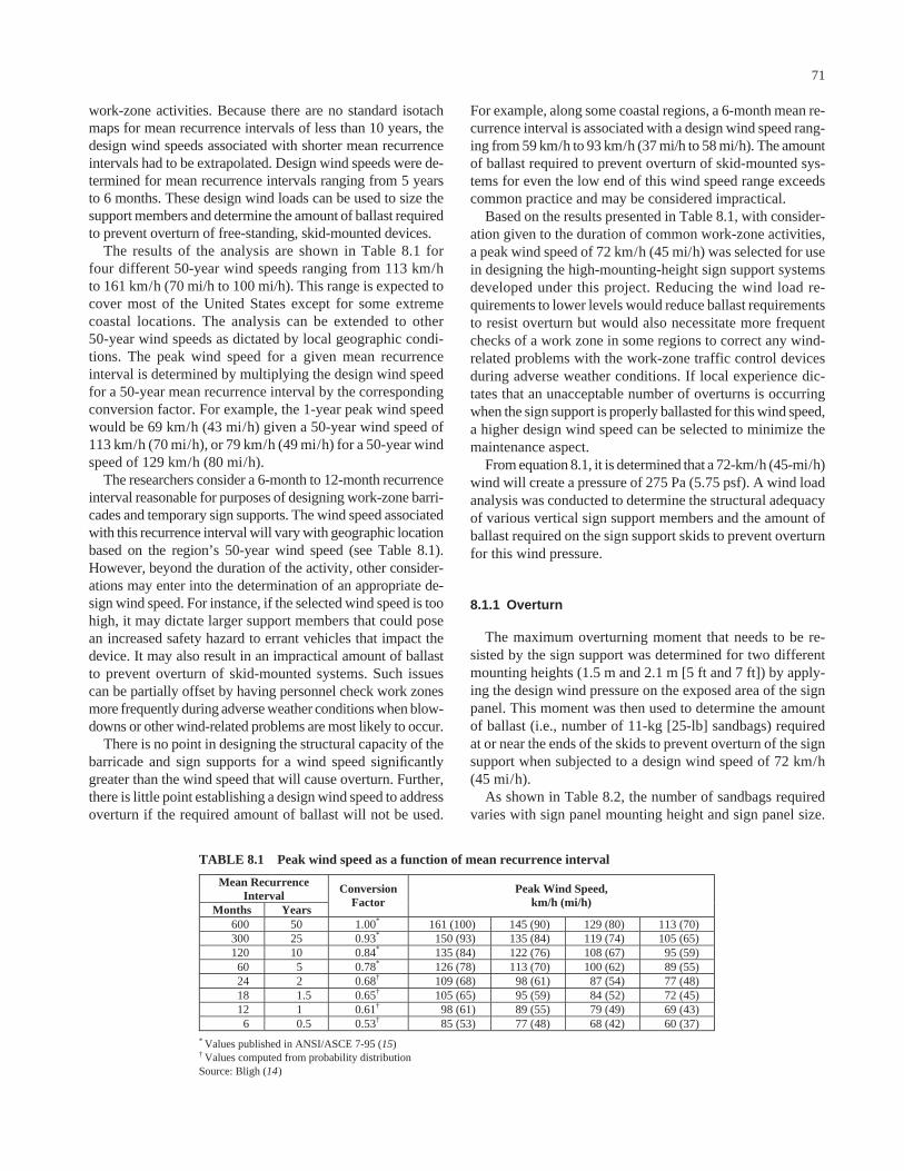
work-zone activities. Because there are no standard isotachmaps for mean recurrence intervals of less than 10 years, thedesign wind speeds associated with shorter mean recurrenceintervals had to be extrapolated. Design wind speeds were de-termined for mean recurrence intervals ranging from 5 yearsto 6 months. These design wind loads can be used to size thesupport members and determine the amount of ballast requiredto prevent overturn of free-standing, skid-mounted devices.
The results of the analysis are shown in Table 8.1 for four different 50-year wind speeds ranging from 113 km/hto 161 km/h (70 mi/h to 100 mi/h). This range is expected tocover most of the United States except for some extremecoastal locations. The analysis can be extended to other 50-year wind speeds as dictated by local geographic condi-tions. The peak wind speed for a given mean recurrenceinterval is determined by multiplying the design wind speedfor a 50-year mean recurrence interval by the correspondingconversion factor. For example, the 1-year peak wind speedwould be 69 km/h (43 mi/h) given a 50-year wind speed of113 km/h (70 mi/h), or 79 km/h (49 mi/h) for a 50-year windspeed of 129 km/h (80 mi/h).
The researchers consider a 6-month to 12-month recurrenceinterval reasonable for purposes of designing work-zone barri-cades and temporary sign supports. The wind speed associatedwith this recurrence interval will vary with geographic locationbased on the region’s 50-year wind speed (see Table 8.1).However, beyond the duration of the activity, other consider-ations may enter into the determination of an appropriate de-sign wind speed. For instance, if the selected wind speed is toohigh, it may dictate larger support members that could posean increased safety hazard to errant vehicles that impact thedevice. It may also result in an impractical amount of ballastto prevent overturn of skid-mounted systems. Such issuescan be partially offset by having personnel check work zonesmore frequently during adverse weather conditions when blow-downs or other wind-related problems are most likely to occur.
There is no point in designing the structural capacity of thebarricade and sign supports for a wind speed significantlygreater than the wind speed that will cause overturn. Further,there is little point establishing a design wind speed to addressoverturn if the required amount of ballast will not be used.
71
For example, along some coastal regions, a 6-month mean re-currence interval is associated with a design wind speed rang-ing from 59 km/h to 93 km/h (37 mi/h to 58 mi/h). The amountof ballast required to prevent overturn of skid-mounted sys-tems for even the low end of this wind speed range exceedscommon practice and may be considered impractical.
Based on the results presented in Table 8.1, with consider-ation given to the duration of common work-zone activities,a peak wind speed of 72 km/h (45 mi/h) was selected for usein designing the high-mounting-height sign support systemsdeveloped under this project. Reducing the wind load re-quirements to lower levels would reduce ballast requirementsto resist overturn but would also necessitate more frequentchecks of a work zone in some regions to correct any wind-related problems with the work-zone traffic control devicesduring adverse weather conditions. If local experience dic-tates that an unacceptable number of overturns is occurringwhen the sign support is properly ballasted for this wind speed,a higher design wind speed can be selected to minimize themaintenance aspect.
From equation 8.1, it is determined that a 72-km/h (45-mi/h)wind will create a pressure of 275 Pa (5.75 psf). A wind loadanalysis was conducted to determine the structural adequacyof various vertical sign support members and the amount ofballast required on the sign support skids to prevent overturnfor this wind pressure.
8.1.1 Overturn
The maximum overturning moment that needs to be re-sisted by the sign support was determined for two differentmounting heights (1.5 m and 2.1 m [5 ft and 7 ft]) by apply-ing the design wind pressure on the exposed area of the signpanel. This moment was then used to determine the amountof ballast (i.e., number of 11-kg [25-lb] sandbags) requiredat or near the ends of the skids to prevent overturn of the signsupport when subjected to a design wind speed of 72 km/h(45 mi/h).
As shown in Table 8.2, the number of sandbags requiredvaries with sign panel mounting height and sign panel size.
Mean Recurrence Interval
Months Years
Conversion Factor
Peak Wind Speed, km/h (mi/h)
600 50 1.00* 161 (100) 145 (90) 129 (80) 113 (70) 300 25 0.93* 150 (93) 135 (84) 119 (74) 105 (65) 120 10 0.84* 135 (84) 122 (76) 108 (67) 95 (59) 60 5 0.78* 126 (78) 113 (70) 100 (62) 89 (55) 24 2 0.68† 109 (68) 98 (61) 87 (54) 77 (48) 18 1.5 0.65† 105 (65) 95 (59) 84 (52) 72 (45) 12 1 0.61† 98 (61) 89 (55) 79 (49) 69 (43)
6 0.5 0.53† 85 (53) 77 (48) 68 (42) 60 (37)
* Values published in ANSI/ASCE 7-95 (15)
† Values computed from probability distribution
Source: Bligh (14)
TABLE 8.1 Peak wind speed as a function of mean recurrence interval

Note that the number of sandbags indicated is for one side ofthe sign support only. The total number of sandbags requiredto accommodate wind from either direction would be twicethe number shown in Table 8.2. For example, a sign supportsystem with a 1.2-m × 1.2-m (4-ft × 4-ft) sign panel attachedat a 2.1-m (7-ft) mounting height would require 9 sandbagson both the front and back sides (for a total of 18) to accom-modate a 72-km/h (45-mi/h) design wind speed. Note thatthe analyses were conducted assuming a skid length of 1.5 m(5 ft). An increase in the length of the skids will permit theballast to be moved further out from the barricade, thus de-creasing the number of sandbags required to resist the over-turning moment generated from the applied wind loads.
If the sign mounting height is reduced, the amount of bal-last required to resist overturn for a given wind speed is alsoreduced. Using the same example of a 1.2-m × 1.2-m (4-ft ×4-ft) sign panel, the total number of 11-kg (25-lb) sandbagsrequired to accommodate a 72-km/h (45-mi/h) design windspeed is reduced from 18 to 14 (7 on each side) when themounting height is reduced from 2.1 m to 1.5 m (7 ft to 5 ft).
Although practices vary, the number of sandbags requiredto resist overturn of a high-mounting-height sign support ina 72-km/h (45-mi/h) design wind is more than is typicallyprovided in the field. If these quantities are impractical, thedesign wind speed can be decreased such that the amount ofballast required is reduced to a more practical level. How-ever, as the design wind speed is decreased, the probabilityor percentage of blowdowns or overturns should be expectedto increase. Given the almost daily activity at many work-zonelocations, a certain percentage of blowdowns during stormsor other high-wind-speed events can probably be toleratedand quickly corrected.
8.1.2 Structural Adequacy
Another consideration is the structural adequacy of the sup-port members. There is no need to provide ballast to prevent asystem from overturning in a 72-km/h (45-mi/h) design windspeed if the supports can only withstand a 56-km/h (35-mi/h)design wind speed. Thus, additional analyses were conductedto determine the support member sizes required to accommo-date the selected design wind speed. Two types of materialswere considered: perforated steel tubing and HPPL. The mo-ment generated by the wind load at the base of the supports
72
(see Table 8.3) was compared to the allowable moment capac-ity of various support sizes to identify those with sufficientflexural strength for two different mounting heights (i.e., 1.5 mand 2.1 m [5 ft and 7 ft]) and two different sign panel sizes(i.e., 0.9 m × 0.9 m and 1.2 m × 1.2 m [3 ft × 3 ft and 4 ft ×4 ft]). The allowable moment for a given support is a functionof both the dimensions and material properties of the support.
Perforated Steel Tube
The square, perforated tube used in steel-framed barricadesand sign support systems is commonly manufactured fromASTM A-446 steel, which has a yield stress of 227.5 MPa(33,000 psi). A cross section through the perforated section ofthe tubing was used in the analyses. As shown in Table 8.4,the section modulus varies with the size and thickness of thetubing. For example, the section modulus for a 44-mm (13⁄4-in)square, 12-gauge tube is 6.7 mm3 (0.265 in3). Thus, the allow-able moment capacity based on yield is 988 N�m (729 ft-lb).When compared to the required moment capacities presentedin Table 8.3, a single 44-mm (13⁄4-in) square, 12-gauge tubecan be seen to have sufficient flexural capacity to accommo-date a 1.2-m × 1.2-m (4-ft × 4-ft) sign panel at a mountingheight of 1.5 m (5 ft). Table 8.5 shows the smallest tube neededto support the moment produced by a 72 km/h (45 mi/h)design wind on a 1.2 m × 1.2 m (4 ft × 4 ft) sign panel at dif-ferent mounting heights for both single and dual supports.
Unless the proper amount of ballast (see Table 8.2) is pro-vided at the base of the structure, the system will overturnbefore the structural capacity of the supports is reached. If theability to accommodate a greater design wind speed is desired,the size of the supports could be increased beyond the sizesindicated in Table 8.5. However, the effect of the larger sup-ports on the crash performance of the system would need tobe considered.
Hollow-Profile Plastic
The sign support system also can be fabricated from a vari-ety of virgin or recycled plastics including PVC and HDPE.One of the advantages of the hollow-profile plastic is its lightweight. Further, it can be readily cut and drilled using stan-dard woodworking tools.
Sign Panel Size Sign Panel Mounting
Height, m (ft) 0.9 m x 0.9 m
(3 ft x 3 ft) 1.2 m x 1.2 m
(4 ft x 4 ft) 1.5 (5) 3 7
2.1 (7) 4 9
Note: Sandbags are assumed to be placed at or near the endsof 1.5-m (5-ft) long skids.
TABLE 8.2 Number of 11 kg (25 lb) sandbagsrequired on each side of sign support base
Sign Panel Size Sign Panel Mounting
Height, m (ft) 0.9 m x 0.9 m
(3 ft x 3 ft) 1.2 m x 1.2 m
(4 ft x 4 ft)
1.5 (5) 549 N·m
(405 ft-lb) 976 N·m
(720 ft-lb)
2.1 (7) 690 N·m
(509 ft-lb) 1226 N·m (904 ft-lb)
TABLE 8.3 Wind-induced moment at signsupport base
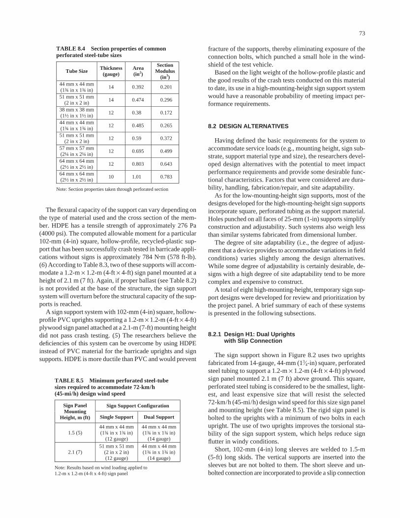
The flexural capacity of the support can vary depending onthe type of material used and the cross section of the mem-ber. HDPE has a tensile strength of approximately 276 Pa(4000 psi). The computed allowable moment for a particular102-mm (4-in) square, hollow-profile, recycled-plastic sup-port that has been successfully crash tested in barricade appli-cations without signs is approximately 784 N�m (578 ft-lb).(6) According to Table 8.3, two of these supports will accom-modate a 1.2-m × 1.2-m (4-ft × 4-ft) sign panel mounted at aheight of 2.1 m (7 ft). Again, if proper ballast (see Table 8.2)is not provided at the base of the structure, the sign supportsystem will overturn before the structural capacity of the sup-ports is reached.
A sign support system with 102-mm (4-in) square, hollow-profile PVC uprights supporting a 1.2-m × 1.2-m (4-ft × 4-ft)plywood sign panel attached at a 2.1-m (7-ft) mounting heightdid not pass crash testing. (5) The researchers believe thedeficiencies of this system can be overcome by using HDPEinstead of PVC material for the barricade uprights and signsupports. HDPE is more ductile than PVC and would prevent
73
fracture of the supports, thereby eliminating exposure of theconnection bolts, which punched a small hole in the wind-shield of the test vehicle.
Based on the light weight of the hollow-profile plastic andthe good results of the crash tests conducted on this materialto date, its use in a high-mounting-height sign support systemwould have a reasonable probability of meeting impact per-formance requirements.
8.2 DESIGN ALTERNATIVES
Having defined the basic requirements for the system toaccommodate service loads (e.g., mounting height, sign sub-strate, support material type and size), the researchers devel-oped design alternatives with the potential to meet impactperformance requirements and provide some desirable func-tional characteristics. Factors that were considered are dura-bility, handling, fabrication/repair, and site adaptability.
As for the low-mounting-height sign supports, most of thedesigns developed for the high-mounting-height sign supportsincorporate square, perforated tubing as the support material.Holes punched on all faces of 25-mm (1-in) supports simplifyconstruction and adjustability. Such systems also weigh lessthan similar systems fabricated from dimensional lumber.
The degree of site adaptability (i.e., the degree of adjust-ment that a device provides to accommodate variations in fieldconditions) varies slightly among the design alternatives.While some degree of adjustability is certainly desirable, de-signs with a high degree of site adaptability tend to be morecomplex and expensive to construct.
A total of eight high-mounting-height, temporary sign sup-port designs were developed for review and prioritization bythe project panel. A brief summary of each of these systemsis presented in the following subsections.
8.2.1 Design H1: Dual Uprights with Slip Connection
The sign support shown in Figure 8.2 uses two uprightsfabricated from 14-gauge, 44-mm (13⁄4-in) square, perforatedsteel tubing to support a 1.2-m × 1.2-m (4-ft × 4-ft) plywoodsign panel mounted 2.1 m (7 ft) above ground. This square,perforated steel tubing is considered to be the smallest, light-est, and least expensive size that will resist the selected 72-km/h (45-mi/h) design wind speed for this size sign paneland mounting height (see Table 8.5). The rigid sign panel isbolted to the uprights with a minimum of two bolts in eachupright. The use of two uprights improves the torsional sta-bility of the sign support system, which helps reduce signflutter in windy conditions.
Short, 102-mm (4-in) long sleeves are welded to 1.5-m(5-ft) long skids. The vertical supports are inserted into thesleeves but are not bolted to them. The short sleeve and un-bolted connection are incorporated to provide a slip connection
Tube Size Thickness (gauge)
Area (in2)
Section Modulus
(in3) 44 mm x 44 mm (1¾ in x 1¾ in)
14 0.392 0.201
51 mm x 51 mm (2 in x 2 in)
14 0.474 0.296
38 mm x 38 mm (1½ in x 1½ in)
12 0.38 0.172
44 mm x 44 mm (1¾ in x 1¾ in)
12 0.485 0.265
51 mm x 51 mm (2 in x 2 in)
12 0.59 0.372
57 mm x 57 mm (2¼ in x 2¼ in)
12 0.695 0.499
64 mm x 64 mm (2½ in x 2½ in)
12 0.803 0.643
64 mm x 64 mm (2½ in x 2½ in)
10 1.01 0.783
Note: Section properties taken through perforated section
TABLE 8.4 Section properties of commonperforated steel-tube sizes
Sign Support Configuration Sign Panel Mounting
Height, m (ft) Single Support Dual Support
1.5 (5) 44 mm x 44 mm (1¾ in x 1¾ in)
(12 gauge)
44 mm x 44 mm(1¾ in x 1¾ in)
(14 gauge)
2.1 (7) 51 mm x 51 mm
(2 in x 2 in) (12 gauge)
44 mm x 44 mm(1¾ in x 1¾ in)
(14 gauge)
Note: Results based on wind loading applied to1.2-m x 1.2-m (4-ft x 4-ft) sign panel
TABLE 8.5 Minimum perforated steel-tubesizes required to accommodate 72-km/h (45-mi/h) design wind speed

that will facilitate the release of the uprights after impact. The102-mm (4-in) sleeve is considered sufficient for developingthe moment capacity of the upright to accommodate serviceloads. A horizontal cross brace connects the two uprights justabove the sleeves to provide some lateral stability to the signsupport frame. The sign panel provides additional cross brac-ing of the system.
Transportation and erection of this system are also facili-tated by the unbolted slip connection of the uprights insidethe sleeves. The simple design allows minimal adjustabilityto account for varying terrain considerations. Roadside slopecan be accommodated by lowering the attachment points ofthe downhill upright on the sign panel as shown in Figure 8.3.Any telescopic adjustment of the uprights is limited by theshort sleeve.
A version of this design with a 1.5-m (5-ft) mounting heightis shown in Figure 8.4. This design is similar to that shown inFigure 8.2 with the exception of the upright length, which hasbeen decreased to accommodate the lower mounting height.
74
The 1.5-m (5-ft) mounting height is generally believed to bemore critical from an impact performance standpoint becausethe lower center of mass decreases the point of rotation of thesupports and increases rotational velocity. These factors com-bine to create an increased propensity for secondary impactsof the supports and sign panel with the windshield and roof ofthe impacting vehicle. Thus, if a 1.5-m (5-ft) mounting heightis desired, it is recommended that any crash testing be con-ducted using a 1.5-m (5-ft) mounting height. If successful, thesame sign support system would generally be consideredacceptable for a 2.1-m (7-ft) mounting height.
A similar temporary sign support design in which the up-rights were bolted inside 152-mm (6-in) long sleeves ex-hibited unacceptable impact performance. (11) In the absenceof a release or slip mechanism, the uprights yielded aroundthe front end of the impacting vehicle, causing the sign paneland uprights to contact the top of the windshield and frontedge of the roof with sufficient force to induce unacceptabledamage. The shorter sleeve and unbolted connection are in-
Figure 8.2. Design H1: dual steel-upright sign support with slip connection.
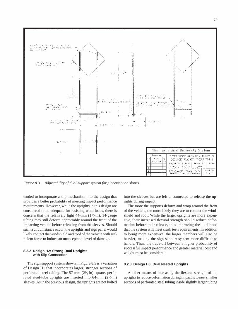
tended to incorporate a slip mechanism into the design thatprovides a better probability of meeting impact performancerequirements. However, while the uprights in this design areconsidered to be adequate for resisting wind loads, there isconcern that the relatively light 44-mm (13⁄4-in), 14-gaugetubing may still deform appreciably around the front of theimpacting vehicle before releasing from the sleeves. Shouldsuch a circumstance occur, the uprights and sign panel wouldlikely contact the windshield and roof of the vehicle with suf-ficient force to induce an unacceptable level of damage.
8.2.2 Design H2: Strong Dual Uprights with Slip Connection
The sign support system shown in Figure 8.5 is a variationof Design H1 that incorporates larger, stronger sections ofperforated steel tubing. The 57-mm (21⁄4-in) square, perfo-rated steel-tube uprights are inserted into 64-mm (21⁄2-in)sleeves. As in the previous design, the uprights are not bolted
75
into the sleeves but are left unconnected to release the up-rights during impact.
The more the supports deform and wrap around the frontof the vehicle, the more likely they are to contact the wind-shield and roof. While the larger uprights are more expen-sive, their increased flexural strength should reduce defor-mation before their release, thus improving the likelihoodthat the system will meet crash test requirements. In additionto being more expensive, the larger members will also beheavier, making the sign support system more difficult tohandle. Thus, the trade-off between a higher probability ofsuccessful impact performance and greater material cost andweight must be considered.
8.2.3 Design H3: Dual Nested Uprights
Another means of increasing the flexural strength of theuprights to reduce deformation during impact is to nest smallersections of perforated steel tubing inside slightly larger tubing
Figure 8.3. Adjustability of dual-support system for placement on slopes.

to form a composite section. In the design shown in Figure 8.6,a 44-mm (13⁄4-in) square, perforated steel tube is nested in-side a 51-mm (2-in) square tube. To maintain the slip con-nection without using a third size of tubing for the sleeves andskids, the nested uprights are bolted together in a manner thatleaves a 102-mm (4-in) portion of the 44-mm (13⁄4-in) squareinner tube extended past the end of the outer tube. This ex-tended portion is inserted into a 51-mm (2-in) square, 102-mm(4-in) long sleeve that is welded to a 51-mm (2-in) square,perforated steel-tube skid.
When finalizing the designs of high-mounting-height sys-tems for consideration by the panel, the researchers learnedthat a system similar to Design H3 was successfully crashtested for the Michigan DOT. (16) The successful crash testof the similar system led the panel to not prioritize Design H3under this study. However, this design is discussed in the re-port for informational purposes and to make readers aware ofthe successfully crash-tested sign support system.
76
8.2.4 Design H4: Dual Uprights with Knee Braces
Another potential method for controlling deformation ofthe uprights without increasing their size is to add a kneebrace between the supports and skids as shown in Figure 8.7.The knee brace is attached to the uprights above the bumperheight of the impacting vehicle. In theory, upon impact, thedeformation and rotation of the uprights toward the car willbe initially resisted by the knee brace. Typically, the uprightswill hinge and rotate about a point near the vehicle bumper,which is the first point of contact between the uprights andvehicle. The presence of the knee braces above bumper heightwill constrain the movement of the uprights toward the vehi-cle until a hinge forms in the uprights above the height of theknee braces or the uprights fracture near the points of attach-ment to the knee braces. The concept is that the sign supportsystem will have been accelerated by the impacting vehicle
Figure 8.4. Dual steel-upright sign support with 1.5-m (5-ft) mounting height.
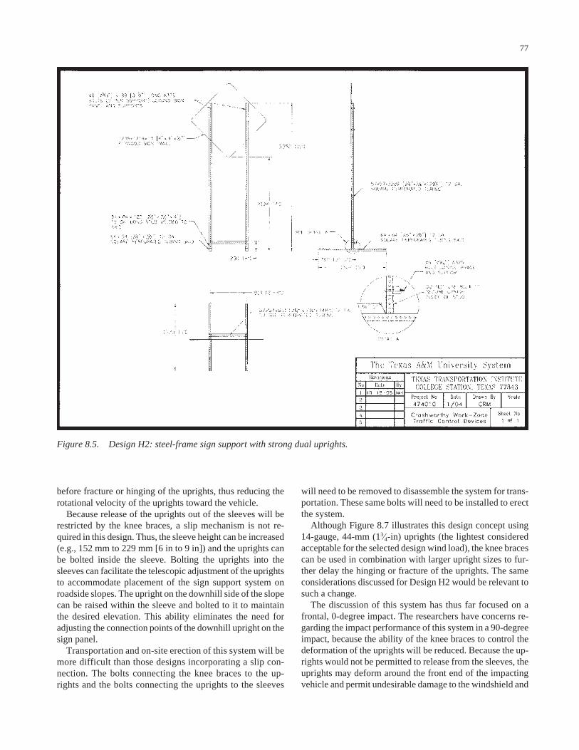
before fracture or hinging of the uprights, thus reducing therotational velocity of the uprights toward the vehicle.
Because release of the uprights out of the sleeves will berestricted by the knee braces, a slip mechanism is not re-quired in this design. Thus, the sleeve height can be increased(e.g., 152 mm to 229 mm [6 in to 9 in]) and the uprights canbe bolted inside the sleeve. Bolting the uprights into thesleeves can facilitate the telescopic adjustment of the uprightsto accommodate placement of the sign support system onroadside slopes. The upright on the downhill side of the slopecan be raised within the sleeve and bolted to it to maintainthe desired elevation. This ability eliminates the need foradjusting the connection points of the downhill upright on thesign panel.
Transportation and on-site erection of this system will bemore difficult than those designs incorporating a slip con-nection. The bolts connecting the knee braces to the up-rights and the bolts connecting the uprights to the sleeves
77
will need to be removed to disassemble the system for trans-portation. These same bolts will need to be installed to erectthe system.
Although Figure 8.7 illustrates this design concept using14-gauge, 44-mm (13⁄4-in) uprights (the lightest consideredacceptable for the selected design wind load), the knee bracescan be used in combination with larger upright sizes to fur-ther delay the hinging or fracture of the uprights. The sameconsiderations discussed for Design H2 would be relevant tosuch a change.
The discussion of this system has thus far focused on afrontal, 0-degree impact. The researchers have concerns re-garding the impact performance of this system in a 90-degreeimpact, because the ability of the knee braces to control thedeformation of the uprights will be reduced. Because the up-rights would not be permitted to release from the sleeves, theuprights may deform around the front end of the impactingvehicle and permit undesirable damage to the windshield and
Figure 8.5. Design H2: steel-frame sign support with strong dual uprights.

roof. Such behavior may be overcome through the use of alarger, stronger perforated tube for the uprights.
8.2.5 Design H5: Single Upright with Slip Connection
As has been discussed, increasing the size of the dual perfo-rated steel-tube uprights above the minimum sizes required tohandle wind loads may be desirable in order to incrementallyincrease the probability of successful impact performance. Ifthe size of the upright is 51-mm (2-in) square, 12 gauge orlarger, Table 8.5 indicates that a single support can accom-modate service loads associated with a 1.2-m × 1.2-m (4-ft ×4-ft) sign panel mounted at a height of 2.1 m (7 ft).
The sign support system shown in Figure 8.8 has an I-shapedbase with one central upright fabricated from 51-mm (2-in)square, perforated steel tubing. The central member of theI-shaped base is welded to the center of each skid and a shortsleeve is welded to the center of this central member. Theupright is inserted into the sleeve but is not bolted to it. This
78
slip mechanism is similar to that incorporated into DesignH1. The rigid sign panel is mounted to the single uprightusing a minimum of two bolts.
This system is a relatively simple design and requires lessmaterial than a dual-upright system. However, the savings inmaterial cost are likely offset by a small increase in the re-quired amount of welding. Handling may be facilitated bythe lighter weight of the single upright. Assembly and dis-assembly also may be nominally faster because there is onlyone upright to insert or remove from a sleeve.
However, signs mounted on single vertical supports willbe more susceptible to flutter in windy conditions. Further,this design does not possess any side-to-side adjustability forplacement on slopes.
8.2.6 Design H6: Dual Uprights with Raised Slip Joint
Another alternative for a dual-upright sign support systemis shown in Figure 8.9. The sizes of the uprights, sleeves, and
Figure 8.6. Design H3: steel-frame sign support with dual nested uprights.

skids are similar to those used in Design H1. The 44-mm(13⁄4-in) square, perforated steel-tube uprights are insertedinto 51-mm (2-in) square sleeves that are welded to 1.5-m (5-ft) long skids. The plywood sign panel is bolted to eachupright at two locations.
The difference between this design and Design H1 is theincreased length of the sleeve. The sleeve is increased inlength from 102 mm to 863 mm (4 in to 34 in). The top ofthe sleeve is 914 mm (36 in) above ground, which isgreater than the bumper height of passenger vehicles. Theuprights are inserted inside the sleeves only to a depth of102 mm (4 in) and they are not bolted to the sleeves. A boltthrough the sleeve is used as a shelf for the inserted uprightto rest on.
This connection detail effectively raises the height of theslip joint from near ground level to above bumper height. Intheory, this higher slip joint will reduce deformation of theuprights before their release from the slip connection and willresult in a higher point of rotation of the uprights and signpanel after their release. The probability of secondary con-
79
tact between the sign panel and the windshield of the impact-ing vehicle should thereby be reduced.
The taller sleeves welded to the skids may make transpor-tation of this system more cumbersome than some of theother designs. The cross braces can be attached to uprightsjust above the sleeves rather than to the bottom of the sleevesto permit each skid to be handled separately and laid downfor ease of transport. As with the other systems incorporat-ing a similar connection, the deployment of this system isfacilitated by the simple slip connection.
8.2.7 Design H7: Dual Three-Piece Uprights
The sign support system shown in Figure 8.10 has a raisedslip joint similar to Design H6. It is differentiated from De-sign H6 through the addition of an upper slip joint below the sign panel. Thus, the upright is effectively composed ofthree pieces of tubing. The middle section of the three-pieceupright slides into the sleeve to form a slip connection simi-lar to the one used in Design H6. The insertion depth into the
Figure 8.7. Design H4: dual steel-upright sign support with knee braces.

sleeve is limited to 102 mm (4 in) by a stop bolt on which thelower end of the middle section rests. The upper section ofthe three-piece upright is the same size as the sleeve and slidesover the top end of the middle section. The insertion depth ofthe middle section into the upper section is limited to 102 mm(4 in) by a stop bolt on which the lower end of the upper sec-tion rests. Thus, there are two slip connections in this system.
In theory, this design should permit the upright to separateinto two pieces during impact. Each component will thus havea mass that is less than the combined mass of the system,which should help reduce the severity of contact with thevehicle should a secondary impact occur. Release of the signpanel at an increased height above ground will also poten-tially increase the height of its point of rotation, thereby re-ducing the likelihood of secondary contact with the impact-ing vehicle.
The slip connections should result in quick assembly. How-ever, fabrication and handling may be complicated by themultiple components that compose the system.
80
8.2.8 Design H8: Dual HDPE Uprights
Design H8, shown in Figure 8.11, is a combination wood andplastic support system. The skids are fabricated from wooden51-mm × 152-mm (2-in × 6-in) dimensional lumber. Theuprights are lightweight, hollow-profile, 102-mm × 102-mm(4-in × 4-in) tubes fabricated from HDPE similar to thoseused in some barricade designs. The HDPE uprights are in-serted between the legs of each skid. Rotation of the uprightsis resisted by two short, hollow-profile plastic blocks boltedinside the skids on either side of the uprights. This slip con-nection will permit the uprights to release from the skidsupon impact.
This design is relatively inexpensive and easily constructedfrom readily available materials. However, the hollow-profileplastic and dimensional lumber may be less durable than thesteel-frame designs, and handling will be more difficult be-cause the wooden skids increase the weight. If desired, theweight of the system can be reduced to improve handling
Figure 8.8. Design H5: single steel-upright sign support with slip connection.
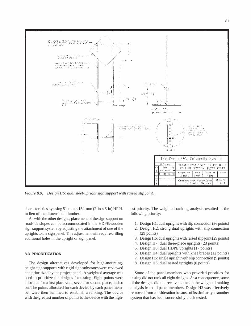
characteristics by using 51-mm × 152-mm (2-in × 6-in) HPPLin lieu of the dimensional lumber.
As with the other designs, placement of the sign support onroadside slopes can be accommodated in the HDPE/woodensign support system by adjusting the attachment of one of theuprights to the sign panel. This adjustment will require drillingadditional holes in the upright or sign panel.
8.3 PRIORITIZATION
The design alternatives developed for high-mounting-height sign supports with rigid sign substrates were reviewedand prioritized by the project panel. A weighted average wasused to prioritize the designs for testing. Eight points wereallocated for a first place vote, seven for second place, and soon. The points allocated for each device by each panel mem-ber were then summed to establish a ranking. The devicewith the greatest number of points is the device with the high-
81
est priority. The weighted ranking analysis resulted in thefollowing priority:
1. Design H1: dual uprights with slip connection (36 points)2. Design H2: strong dual uprights with slip connection
(29 points)3. Design H6: dual uprights with raised slip joint (29 points)4. Design H7: dual three-piece uprights (23 points)5. Design H8: dual HDPE uprights (17 points)6. Design H4: dual uprights with knee braces (12 points)7. Design H5: single upright with slip connection (9 points)8. Design H3: dual nested uprights (0 points)
Some of the panel members who provided priorities fortesting did not rank all eight designs. As a consequence, someof the designs did not receive points in the weighted rankinganalysis from all panel members. Design H3 was effectivelyremoved from consideration because of its similarity to anothersystem that has been successfully crash tested.
Figure 8.9. Design H6: dual steel-upright sign support with raised slip joint.

The panel’s rankings were used to establish a plan for crashtesting high-mounting-height work-zone sign supports withrigid sign substrates. Details of the full-scale crash tests con-ducted on these designs are described in the following section.
8.4 FULL-SCALE CRASH TESTING
All crash test and data analysis procedures used to evaluatethe high-mounting-height sign support systems were in accor-dance with the guidelines presented in NCHRP Report 350.Appendix C presents brief descriptions of these procedures.Additionally, the FHWA windshield damage classificationcriteria were followed in assessing damage to the windshield.
The tests followed the impact conditions of test designation3-71 of NCHRP Report 350. Test 3-71 involves an 820-kg(1808-lb) passenger car impacting the device at a speed of100 km/h (62 mi/h). This test is considered to be the criticalone for most work-zone devices because the propensity foroccupant compartment intrusion is increased. A 50th percen-
82
tile male anthropomorphic dummy was placed in the driver’sposition and restrained with standard equipment lap and shoul-der belts, thus increasing the test inertial weight of the vehi-cle to approximately 900 kg (1984 lb).
NCHRP Report 350 suggests considering the use of a2000-kg (4409-lb) pickup truck for evaluation of work-zonetraffic control devices in lieu of or in addition to the 820-kg(1808-lb) passenger car. The choice depends on the geome-try of the test article in relation to the front profile of eachvehicle. The choice of test vehicle is not as obvious for high-mounting-height sign supports as it is for barricades and low-mounting-height sign supports.
The frontal profile of pickup trucks is “squared off” (i.e., the angle of the hood with respect to the front end of thevehicle is close to 90 degrees), whereas the Geo Metro has amore aerodynamic, highly sloped profile. The hood height ofa 3⁄4-ton pickup truck is approximately 42 in. On the GeoMetro, the edge of the hood is offset from the top of thebumper and the “breakover point” on the front end is the top
Figure 8.10. Design H7: steel-frame sign support with three-piece uprights.

of the bumper, which is at a height of approximately 20 in.Thus, the application point of the impact load on a sign sup-port by a pickup truck will be higher and nearer to center ofmass of the support system than the impact load applied by aGeo Metro. The higher point of load application from thepickup truck will induce more forward (i.e., translational)motion and less rotational velocity of a sign support systemthan a small passenger car. Thus, the severity of any second-ary contact that may occur between the sign support and thewindshield or roof of a pickup truck would be reduced.
Therefore, while the possibility of undesirable interaction ofa pickup truck with high-mounting-height sign support sys-tems should not be discounted, the small car is generally re-garded to be more critical in most cases. Because availableresources precluded testing with both vehicles, the researchersdecided to evaluate the high-mounting-height sign supportsystems solely with the 820-kg passenger car. It should benoted that precedence has been set through numerous crashtests for using the 820-kg passenger car in tests of both per-
83
manent and temporary high-mounting-height sign supportsystems.
Crash tests on the high-mounting-height sign support wereconducted with a plywood sign panel at a mounting height of1.5 m (5 ft). The 1.5-m (5-ft) mounting height is consideredmore critical than the 2.1-m (7-ft) mounting height in regardto impact performance. Therefore, if a system demonstratesacceptable impact performance at a 1.5-m (5-ft) mountingheight, a similar system with a 2.1-m (7-ft) mounting heightalso would generally be considered acceptable.
Two separate sign support systems were offset approxi-mately 9 m (30 ft) from one another and placed at differentorientations with respect to the path of the vehicle. The firstsupport was oriented perpendicular to the vehicle path for ahead-on impact at 0 degree. The second support, placed be-hind the first sign support, was oriented parallel to the vehi-cle path for an end-on impact at 90 degrees. The supportswere placed on a paved concrete surface and ballasted withsandbags.
Figure 8.11. Design H8: dual HDPE-upright sign support with slip connection.

8.4.1 Test 8
Test Article
In accordance with the established priorities, the first high-mounting-height sign support tested was Design H1: dualuprights with slip connection. Although this system did nothave the highest probability of meeting impact performancerequirements from among the various design alternatives, itwas the most economical of the dual-upright support systemsfabricated from perforated steel tubing. Figure 8.12 presentsdetails of this support system as it was tested. The sign sup-port uses two uprights fabricated from 44 mm (13⁄4-in) square,14-gauge perforated steel tubing. A 1.2-m × 1.2-m × 13-mm(4-ft × 4-ft × 1⁄2-in) plywood sign panel is attached to eachupright using two 8-mm (5⁄16-in) diameter, 76-mm (3-in) long,A325 or equivalent grade bolts. The mounting height from theground to the bottom edge of the sign panel was 1.5 m (5 ft).
A 102-mm (4-in) long sleeve fabricated from 51-mm (2-in)square, 12-gauge perforated steel tubing is vertically weldedto the center of a 1.5-m (5-ft) long skid fabricated from thesame material. The uprights are inserted into the sleeves butare not bolted to them. A horizontal cross brace fabricatedfrom 44-mm (13⁄4-in) square, 14-gauge perforated steel tubingis bolted to each upright just above the height of the sleeveusing 8-mm (5⁄16-in) diameter, A325 or equivalent bolts.
Two identical sign support systems were placed on a pavedconcrete surface in the path of the vehicle approximately 9 m(30 ft) apart from one another—one perpendicular to thepath of the vehicle and one parallel to the path of the vehicle.Each system was ballasted with four 18-kg (40-lb) sandbags.Photographs of the completed test installation are shown inFigure 8.13.
Test Vehicle
A 1995 Geo Metro, shown in Figure 8.14, was used for thecrash test. Test inertia weight of the vehicle was 820 kg(1808 lb), and its gross static weight was 897 kg (1978 lb).The height to the lower edge of the vehicle front bumper was400 mm (15.7 in), and the height to the upper edge of thefront bumper was 525 mm (20.7 in). Additional dimensionsand information on the vehicle are given in Appendix D, Fig-ure D.8. The vehicle was directed into the installation usingthe cable reverse tow and guidance system and was releasedto be free-wheeling and unrestrained just before impact.
Impact Description
The 897-kg (1978-lb) vehicle, traveling at a speed of100.1 km/h (62.2 mi/h), impacted the first sign support head-on at 0 degree with the centerline of the vehicle aligned withthe centerline of the support. Shortly after impact, the legs ofthe sign support began to deform around the front of the vehi-
cle, causing the sign panel to begin rotating toward the vehi-cle. By 0.063 s, the vehicle lost contact with the legs, and thevehicle was traveling at a speed of 96.9 km/h (60.2 mi/h).The sign panel contacted the vehicle at its roofline at 0.086 s.The left leg separated from the sign panel at the lower con-nection at 0.115 s; the right leg separated from the sign panelat the lower connection at 0.144 s; and the right leg separatedfrom the sign panel at the upper connection at 0.162 s. At0.232 s, the vehicle lost contact with the sign panel and wastraveling at a speed of 94.8 km/h (58.9 mi/h).
At 0.343 s, the vehicle contacted the second temporarysign support end-on at 90 degrees. Speed of the vehicle attime of impact was 92.5 km/h (57.5 mi/h). The legs began todeform and wrap around the front of the vehicle at 0.348 s.The corner of the sign panel rotated into the vehicle and con-tacted the windshield at 0.414 s. The corner of the panel pen-etrated the windshield at 0.426 s and reached a maximumpenetration of 302 mm (11.9 in) at 0.466 s. As the vehiclecontinued forward, the sign panel rose up to the roof, and thevehicle traveled out of view of the cameras at 0.627 s, at aspeed of 79.2 km/h (49.2 mi/h).
Brakes on the vehicle were applied at 1.9 s. The vehiclecame to rest 104.9 m (344.0 ft) downstream of impact and2.1 m (7.0 ft) to the left of centerline. Sequential photographsof the test period are shown in Appendix E, Figure E.8.
Test Results
Both sign supports readily activated at impact by yieldingto the vehicle. The debris was scattered over an area 90.5 m(297.0 ft) long and 18.2 m (60.0 ft) to the right and 4.0 m(13.0 ft) to the left of the initial impact point.
The vehicle remained upright during and after the collisionevent. Damage to the vehicle is shown in Figure 8.15. Thefront bumper, hood, and roof were deformed. Maximum crushto the exterior of the vehicle was 10 mm (0.4 in) centeredalong the front at bumper height. The roof was deformed atcenterline near the edge of the windshield and pushed down-ward 200 mm (7.9 in). The windshield was torn and sepa-rated from its frame. The FHWA windshield damage classi-fication was a combination of Case 1 and Case 2. There wasno other measurable occupant compartment deformation.
In the longitudinal direction, the occupant impact velocitywas 2.5 m/s (8.2 ft/s) at 0.450 s, the highest 0.010-s occupantridedown acceleration was −2.0 g’s from 0.466 s to 0.476 s,and the maximum 0.050-s average acceleration was −1.6 g’sbetween 0.002 s and 0.052 s. In the lateral direction, theoccupant impact velocity was 0.2 m/s (0.7 ft/s) at 0.450 s, thehighest 0.010-s occupant ridedown acceleration was −0.9 gfrom 0.462 s to 0.472 s, and the maximum 0.050-s averagewas −0.3 g between 0.004 s and 0.054 s. These data and otherpertinent information from the test are summarized in Fig-ure 8.16. Vehicle angular displacements and accelerationsversus time traces are presented in Appendix F, Figures F.50through F.56.
84

Figure 8.12. Details of the dual uprights with slip connection for Test 8.

86
Figure 8.13. Dual uprights with slip connection before Test 8.
Figure 8.14. Vehicle before Test 8. Figure 8.15. Vehicle after Test 8.

0.000 s 0.146 s 0.342 s 0.466 s
General Information Test Agency............................... Test No. .................................... Date ........................................... Test Article Type........................................... Name ......................................... Installation Height, m (ft)............ Material or Key Elements .......... Soil Type and Condition............. Test Vehicle Type........................................... Designation................................ Model ......................................... Mass, kg Curb........................................ Test Inertial............................. Dummy ................................... Gross Static............................
Texas Transportation Institute 474010-8 10-08-2004 High-Mounting-Height Sign Support Dual Uprights with Slip Connection 1.5 (5.0) to Bottom of Sign Panel Two perforated steel-tube legs, skids, and brace with plywood sign Pavement, Dry Production 820C 1995 Geo Metro 805 820 77 897
Impact Conditions Angle, deg ................................. Speed, km/h (mi/h) @ 0 deg ..... Speed, km/h (mi/h) @ 90 deg ... Exit Conditions Speed, km/h (mi/h) .................... Occupant Risk Values Impact Velocity, m/s (ft/s) Longitudinal ............................ Lateral .................................... THIV, km/h................................. Ridedown Accelerations, g’s Longitudinal ............................ Lateral .................................... PHD, g’s .................................... ASI ............................................ Max. 0.050-s Average, g’s Longitudinal ............................ Lateral .................................... Vertical ...................................
0 & 90 100.1 (62.2)92.5 (57.5) 79.2 (49.2) 2.5 (8.2) 0.2 (0.7) 9.1 -2.0 -0.9 2.2 0.14 -1.6 -0.3 -1.1
Test Article Debris Pattern Length, m (ft).................................... Width, m (ft) Left................................................ Right ............................................Vehicle Damage Exterior VDS .............................................. CDC.............................................. Max. Exterior Vehicle Crush, mm (in) .............. Interior OCDI............................................. Max. Occupant Compartment Deformation, mm (in).................Post-Impact Behavior (during 1.0 sec after impact) Max. Yaw Angle, deg.................... Max. Pitch Angle, deg................... Max. Roll Angle, deg ....................
90.5 (297.0) 4.0 (13.0) 18.2 (60.0) 12FD1 12FDEN1 10 (0.4) FS0000000 200 (7.9) -1 2 1
Figure 8.16. Summary of results for Test 8.

88
Test Agency: Texas Transportation Institute Test No.: 474010-8 Test Date: 10/08/2004NCHRP Report 350 Evaluation Criteria Test Results Assessment
Structural Adequacy B. The test article should readily activate in a
predictable manner by breaking away, fracturing, or yielding.
Both tall, dual-leg sign supports readily activated as designed by yielding and fracturing.
Pass
Occupant Risk D. Detached elements, fragments, or other debris
from the test article should not penetrate or show potential for penetrating the occupant compartment, or present an undue hazard to other traffic, pedestrians, or personnel in a work zone. Deformations of, or intrusions into, the occupant compartment that could cause serious injuries should not be permitted.
Debris remained scattered along the vehicle path. The roof of the vehicle was deformed inward 200 mm (7.9 in). The windshield was torn and separated from its frame (FHWA Case 1 and 2). During the test, the sign panel reached a maximum penetration of 302 mm (11.9 in). There was no other measurable occupant compartment deformation.
Fail
E. Detached elements, fragments, or other debris from the test article, or vehicular damage should not block the driver’s vision or otherwise cause the driver to lose control of the vehicle.
The driverís vision was not blocked. Pass
F. The vehicle should remain upright during and after collision although moderate roll, pitching, and yawing are acceptable.
The vehicle remained upright throughout and after the crash period.
Pass
H. Occupant impact velocities should satisfy the following:
Occupant Velocity Limits (m/s)
Longitudinal occupant impact velocity was 2.5 m/s (8.2 ft/s).
Pass
Component Preferred Maximum Longitudinal 3 5
I. Occupant ridedown accelerations should satisfy the following:
Occupant Ridedown Acceleration Limits (g’s) Component Preferred Maximum Longitudinal and
lateral 15 20
Longitudinal ridedown acceleration was -2.0 g’s, and lateral ridedown acceleration was -0.9 g’s.
Pass
Vehicle Trajectory K. After collision, it is preferable that the
vehicle’s trajectory not intrude into adjacent traffic lanes.
The vehicle continued on a straightforward path all along the trajectory path and did not intrude into adjacent lanes.
Pass*
N. Vehicle trajectory behind the test article is acceptable.
The vehicle came to rest behind the test articles.
Pass
*Criterion K preferable, not required.
TABLE 8.6 Performance evaluation summary for Test 8
A summary of the evaluation of the impact performanceof the high-mounting-height sign support with dual uprightswith slip connection is presented in Table 8.6. Because thewindshield was dislodged and torn, and the roof deformeddownward into the occupant compartment 200 mm (7.9 in),Design H1 failed the crash test.
Discussion
This sign support system is considered to be the smallest,lightest, and least expensive dual-support system fabricatedfrom square, perforated steel tubing that can resist the selected72 km/h (45 mi/h) design wind speed for a 1.2-m × 1.2-m(4-ft × 4-ft) sign panel mounted at a height of 1.5 m to 2.1 m(5 ft to 7 ft). However, while the uprights in this design alter-native are considered to be adequate for resisting wind loads,
there was concern that the relatively light 44-mm (13⁄4-in),14-gauge tubing would still deform appreciably around thefront of the impacting vehicle before releasing from the sleeves.Such behavior was observed in the crash test and resulted inthe uprights and sign panel contacting the windshield and roofof the vehicle with sufficient force to induce an unacceptablelevel of damage.
Because the most economical design did not perform sat-isfactorily, the uprights needed to be strengthened and/oralternative release mechanisms needed to be incorporatedthat would limit the amount of deformation to the uprightsand reduce the rotational velocity of the sign panel into thevehicle. A logical next step was to test Design H2, which isa variation of Design H1 that incorporates larger, strongersections of perforated steel tubing. In theory, the increasedflexural strength of the larger uprights would reduce the up-rights’ deformation around the front of the vehicle before their
release, thus improving the likelihood that the system wouldmeet crash-test requirements. This progression in design alsoconformed to the panel’s prioritization.
8.4.2 Test 9
Test Article
In keeping with the priorities of the project panel, andwith consideration of the outcome of Test 8, the next high-mounting-height sign support system tested was Design H2:strong dual uprights with slip connection. Figure 8.17 pre-sents details of this support system as it was tested. The twouprights are fabricated from 57-mm (21⁄4-in) square, 12-gaugeperforated steel tubing. A 1.2-m × 1.2-m × 13-mm (4-ft ×4-ft × 1⁄2-in) plywood sign panel is attached to each uprightusing two 8-mm (5⁄16-in) diameter, A325 or equivalent gradebolts. The mounting height from the ground to the bottomedge of the sign panel was 1.5 m (5 ft).
A 102-mm (4-in) long sleeve fabricated from 64-mm (21⁄2-in)square, 12-gauge perforated steel tubing is vertically weldedto the center of a 1.5-m (5-ft) long skid fabricated from thesame material. The uprights are inserted into the sleeves butare not bolted to them. A horizontal cross brace fabricatedfrom 57-mm (21⁄4-in) square, 12-gauge perforated steel tub-ing is bolted to each upright 0.5 m (1 ft-61⁄2 in) above groundusing 8-mm (5⁄16-in) diameter, A325 or equivalent bolts. Theheight of the cross brace corresponds to the centerline of thebumper of a small passenger car. In the 90-degree impact,the theory was that the cross brace would help transfer momen-tum to both uprights simultaneously and reduce the degree ofdeformation that might otherwise be experienced by the firstupright that is contacted.
Two identical sign support systems were placed on a pavedconcrete surface in the path of the vehicle approximately 9 m(30 ft) apart from one another—one perpendicular to thepath of the vehicle and one parallel to the path of the vehicle.Each system was ballasted with four 18-kg (40-lb) sandbags.Photographs of the completed test installation are shown inFigure 8.18.
Test Vehicle
A 1999 Geo Metro, shown in Figure 8.19, was used forthe crash test. Test inertia weight of the vehicle was 820 kg(1808 lb), and its gross static weight was 897 kg (1978 lb).The height to the lower edge of the vehicle front bumperwas 400 mm (15.7 in), and the height to the upper edge ofthe front bumper was 525 mm (20.7 in). Additional dimen-sions and information on the vehicle are given in Appen-dix D, Figure D.9. The vehicle was directed into the instal-lation using the cable reverse tow and guidance system andwas released to be free-wheeling and unrestrained just be-fore impact.
89
Impact Description
The 897-kg (1978-lb) vehicle, traveling at 99.9 km/h(62.1 mi/h), impacted the first sign support head-on at 0 de-gree, with the centerline of the vehicle aligned with the center-line of the sign support. Shortly after impact, the legs de-formed slightly and then the skids began to slide on the pavedconcrete surface. The sign panel separated from the lowerconnection on the right upright at 0.056 s. At 0.071 s, the vehi-cle lost contact with the uprights with the vehicle traveling ata speed of 90.6 km/h (56.3 mi/h). The sign panel separatedfrom the right leg at the top connection at 0.085 s. As the signsupport frame rotated, the vehicle contacted the skids at0.102 s. At 0.103 s, the left leg separated from its skid, andat 0.112 s, the sign panel contacted the passenger side of theroof of the vehicle at the top edge of the passenger door. Thevehicle lost contact with the right skid at 0.117 s, and the signpanel separated from the upper connection with the left legat 0.129 s. At 0.275 s, the vehicle lost contact with the signpanel, and the vehicle was traveling at a speed of 89.2 km/h(55.4 mi/h).
At 0.356 s, the vehicle contacted the second temporary signsupport end-on at 90 degrees. Speed at time of impact was89.0 km/h (55.3 mi/h). The right leg separated from its skidat 0.388 s. At 0.504 s, the vehicle lost contact with the up-rights, and the vehicle was traveling at a speed of 78.6 km/h(48.9 mi/h). The sign panel contacted the roof of the vehicleat 0.532 s and contacted the windshield at 0.560 s. The vehi-cle lost contact with the sign panel at 0.731 s.
Brakes on the vehicle were applied at 1.9 s. The vehiclecame to rest 86.9 m (285.0 ft) downstream of impact and1.9 m (6.3 ft) to the right of centerline. Sequential photo-graphs of the test period are shown in Appendix E, Figure E.9.
Test Results
Both sign supports readily yielded to the vehicle at impact.The debris was scattered over an area 80.8 m (265.0 ft) longand 3.8 m (12.5 ft) to the right and 4.9 m (16.0 ft) to the leftof the initial impact point.
The vehicle remained upright during and after the collisionevent. Damage to the vehicle is shown in Figure 8.20. Thefront bumper, hood, and roof were deformed. Maximumcrush to the exterior of the vehicle was 170 mm (3.7 in) at thecenter front at bumper height. The roof was deformed inward25 mm (1.0 inch). There was no damage to the windshield,nor was the windshield separated from its frame. There was noother measurable occupant compartment deformation.
In the longitudinal direction, the occupant impact velocitywas 2.5 m/s (8.2 ft/s) at 0.280 s, the highest 0.010-s occupantridedown acceleration was −10.0 g’s from 0.379 s to 0.389 s,and the maximum 0.050-s average acceleration was −4.7 g’sbetween 0.361 s and 0.411 s. In the lateral direction, the occu-pant impact velocity was 0.3 m/s (1.0 ft/s) at 0.280 s, the high-est 0.010-s occupant ridedown acceleration was 2.2 g’s from

Figure 8.17. Details of the strong dual uprights with slip connection for Test 9.

91
Figure 8.18. Strong dual uprights with slip connection for Test 9.
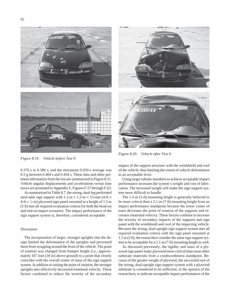
0.376 s to 0.386 s, and the maximum 0.050-s average was0.5 g between 0.404 s and 0.454 s. These data and other per-tinent information from the test are summarized in Figure 8.21.Vehicle angular displacements and accelerations versus timetraces are presented in Appendix F, Figures F.57 through F.63.
As summarized in Table 8.7, the strong, dual-leg perforatedsteel-tube sign support with 1.2-m × 1.2-m × 13-mm (4-ft ×4-ft × 1⁄2-in) plywood sign panel mounted at a height of 1.5 m(5 ft) met all required evaluation criteria for both the head-onand end-on impact scenarios. The impact performance of thesign support system is, therefore, considered acceptable.
Discussion
The incorporation of larger, stronger uprights into the de-sign limited the deformation of the uprights and preventedthem from wrapping around the front of the vehicle. The pointof rotation was changed from bumper height (i.e., approxi-mately 457 mm [18 in] above ground) to a point that closelycoincides with the overall center of mass of the sign supportsystem. In addition to raising the point of rotation, the strongeruprights also effectively decreased rotational velocity. Thesefactors combined to reduce the severity of the secondary
92
impact of the support structure with the windshield and roofof the vehicle, thus limiting the extent of vehicle deformationto an acceptable level.
Using larger tubular members to achieve acceptable impactperformance increases the system’s weight and cost of fabri-cation. The increased weight will make the sign support sys-tem more difficult to handle.
The 1.5-m (5-ft) mounting height is generally believed tobe more critical than a 2.1-m (7-ft) mounting height from animpact performance standpoint because the lower center ofmass decreases the point of rotation of the supports and in-creases rotational velocity. These factors combine to increasethe severity of secondary impacts of the supports and signpanel with the windshield and roof of the impacting vehicle.Because the strong, dual-upright sign support system met allrequired evaluation criteria with the sign panel mounted at1.5 m (5 ft), the researchers consider the same sign support sys-tem to be acceptable for a 2.1-m (7-ft) mounting height as well.
As discussed previously, the rigidity and mass of a ply-wood sign panel make plywood more critical than most othersubstrate materials from a crashworthiness standpoint. Be-cause of the greater weight of plywood, the successful test ofthe strong, dual-upright sign support system with a plywoodsubstrate is considered to be sufficient, in the opinion of theresearchers, to indicate acceptable impact performance of the
Figure 8.19. Vehicle before Test 9.Figure 8.20. Vehicle after Test 9.
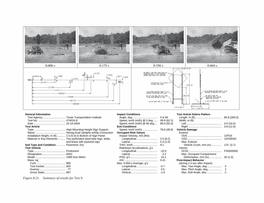
0.000 s 0.175 s 0.356 s 0.604 s
General Information Test Agency............................... Test No. .................................... Date ...........................................Test Article Type........................................... Name ......................................... Installation Height, m (ft)............ Material or Key Elements .......... Soil Type and Condition.............Test Vehicle Type........................................... Designation................................ Model ......................................... Mass, kg Curb........................................ Test Inertial............................. Dummy ................................... Gross Static............................
Texas Transportation Institute 474010-9 10-14-2004 High-Mounting-Height Sign Support Strong Dual Uprights w/Slip Connection 1.5 (5.0) to Bottom of Sign Panel Two perforated steel-tube legs, skids, and brace with plywood sign Pavement, Dry Production 820C 1999 Geo Metro 805 820 77 897
Impact Conditions Angle, deg ................................. Speed, km/h (mi/h) @ 0 deg ..... Speed, km/h (mi/h) @ 90 deg ... Exit Conditions Speed, km/h (mi/h) .................... Occupant Risk Values Impact Velocity, m/s (ft/s) Longitudinal ............................ Lateral .................................... THIV, km/h................................. Ridedown Accelerations, g’s Longitudinal ............................ Lateral .................................... PHD, g’s .................................... ASI ............................................ Max. 0.050-s Average, g’s Longitudinal ............................ Lateral .................................... Vertical ...................................
0 & 90 99.9 (62.1) 89.0 (55.3) 78.6 (48.9) 2.5 (8.2) 0.3 (1.0) 9.1 -10.0 2.2 10.1 0.41 -4.7 0.5 -1.9
Test Article Debris Pattern Length, m (ft).................................... Width, m (ft) Left................................................ Right ............................................Vehicle Damage Exterior VDS .............................................. CDC.............................................. Max. Exterior Vehicle Crush, mm (in) .............. Interior OCDI............................................. Max. Occupant Compartment Deformation, mm (in).................Post-Impact Behavior (during 1.0 sec after impact) Max. Yaw Angle, deg.................... Max. Pitch Angle, deg................... Max. Roll Angle, deg ....................
80.8 (265.0) 4.9 (16.0) 3.8 (12.5) 12FD3 12FDEW2 170 (3.7) FS0000000 25 (1.0) 4 2 -1
Figure 8.21. Summary of results for Test 9.

same sign support system with a comparably sized aluminumsign substrate.
During analysis of the high-speed film of the test, the slipmechanism was observed to not activate as designed. Uponimpact, the sign support system moved as a unit. The uprightsremained inside the sleeves until well after momentum wastransferred to the entire system. This behavior indicates thatthe slip mechanism did not affect the impact response of thesystem; as a result, a longer sleeve (e.g., 152 mm to 229 mm[6 in to 9 in]) can be used without adversely affecting impactperformance. For the same reasons, the researchers concludedthat bolting or pinning the uprights inside the sleeves wouldnot compromise impact performance. Such design modifi-cations would provide better adjustability to accommodateplacement of the sign support on a roadside slope by permit-ting the length of the downhill upright to be extended withinthe sleeve. Although not considered to be a problem in the
94
test, bolting of the uprights inside the sleeves would permitthe system to travel as a unit and reduce any potential debrishazard associated with the skids releasing from the uprights.
8.2.3 Test 10
Test Article
The final high-mounting-height sign support system testedunder this project was Design H6: dual uprights with raisedslip joint. The objective of this test was to determine if rais-ing the slip joint from a height of 152 mm to 870 mm (6 in to341⁄4 in) can improve impact performance and permit smaller,lighter weight tubular sections to be used in lieu of the larger,heavier sections evaluated in Test 9 (Design H2).
The as-tested details of this system are provided in Fig-ure 8.22. The uprights are fabricated from 38-mm (11⁄2-in)
Test Agency: Texas Transportation Institute Test No.: 474010-9 Test Date: 10/14/2004NCHRP Report 350 Evaluation Criteria Test Results Assessment
Structural Adequacy B. The test article should readily activate in a
predictable manner by breaking away, fracturing, or yielding.
Both tall, dual-leg sign supports readily activated as designed by yielding and fracturing.
Pass
Occupant Risk D. Detached elements, fragments, or other debris
from the test article should not penetrate or show potential for penetrating the occupant compartment, or present an undue hazard to other traffic, pedestrians, or personnel in a work zone. Deformations of, or intrusions into, the occupant compartment that could cause serious injuries should not be permitted.
Debris remained scattered along the vehicle path. The roof was deformed inward 25 mm (1.0 in). The windshield was not damaged (no holes or tears), nor was the windshield separated from its frame. There was no other measurable occupant compartment deformation.
Pass
E. Detached elements, fragments, or other debris from the test article, or vehicular damage should not block the driver’s vision or otherwise cause the driver to lose control of the vehicle.
The driver’s vision was not blocked. Pass
F. The vehicle should remain upright during and after collision although moderate roll, pitching, and yawing are acceptable.
The vehicle remained upright throughout and after the crash period.
Pass
H. Occupant impact velocities should satisfy the following:
Occupant Velocity Limits (m/s)
Longitudinal occupant impact velocity was 2.5 m/s (8.2 ft/s).
Pass
Component Preferred Maximum Longitudinal 3 5
I. Occupant ridedown accelerations should satisfy the following:
Occupant Ridedown Acceleration Limits (g’s)
Longitudinal ridedown acceleration was -10.0 g’s and lateral ridedown acceleration was 2.2 g’s.
Pass
Component Preferred Maximum Longitudinal and
lateral 15 20
Vehicle Trajectory K. After collision, it is preferable that the
vehicle’s trajectory not intrude into adjacent traffic lanes.
The vehicle continued on a straightforward path all along the trajectory path and did not intrude into adjacent lanes.
Pass*
N. Vehicle trajectory behind the test article is acceptable.
The vehicle came to rest behind the test articles.
Pass
*Criterion K preferable, not required.
TABLE 8.7 Performance evaluation summary for Test 9

Figure 8.22. Details of the dual uprights with raised slip joint for Test 10.

96
square, 12-gauge perforated steel tubing. A 1.2-m × 1.2-m ×13-mm (4-ft × 4-ft × 1⁄2-in) plywood sign panel is attachedto each upright using two 8-mm (5⁄16-in) diameter, 76-mm(3-in) long, A325 or equivalent grade bolts. The mountingheight from the ground to the bottom edge of the sign panelwas 1.5 m (5 ft).
An 870-mm (341⁄4-in) long sleeve fabricated from 44-mm(13⁄4-in) square, 12-gauge perforated steel tubing is verticallywelded to the center of a 1.5-m (5-ft) long skid fabricatedfrom the same material. The uprights are inserted into thesleeves but are not bolted to them. The insertion depth of theuprights inside the sleeves is only 102 mm (4 in). An 8-mm(5⁄16-in) diameter bolt through the sleeve is used as a shelf forthe inserted upright to rest upon. A horizontal cross brace fab-ricated from 44-mm (13⁄4-in) square, 12-gauge perforated steeltubing is bolted to each sleeve 470 mm (181⁄2 in) above groundusing 8-mm (5⁄16-in) diameter, A325 or equivalent bolts.
Two identical sign support systems were placed on a pavedconcrete surface in the path of the vehicle approximately 9 m(30 ft) apart from one another—one perpendicular to thepath of the vehicle and one parallel to the path of the vehicle.Each system was ballasted with four 18-kg (40-lb) sandbags.Photographs of the completed test installation are shown inFigure 8.23.
Test Vehicle
A 1995 Geo Metro, shown in Figure 8.24, was used for thecrash test. Test inertia weight of the vehicle was 820 kg(1808 lb), and its gross static weight was 897 kg (1978 lb).The height to the lower edge of the vehicle front bumper was400 mm (15.7 in), and the height to the upper edge of thefront bumper was 525 mm (20.7 in). Additional dimensionsand information on the vehicle are given in Appendix D, Fig-ure D.10. The vehicle was directed into the installation usingthe cable reverse tow and guidance system and was releasedto be free-wheeling and unrestrained just before impact.
Impact Description
The 897-kg (1978-lb) vehicle, traveling at a speed of99.6 km/h (61.9 mi/h), impacted the first sign support head-on at 0 degree with the centerline of the vehicle aligned withthe centerline of the support. Shortly after impact, the up-rights began to deform. The sign panel separated from thelower connection to the left upright at 0.015 s and from theupper connection to the left upright at 0.027 s. At 0.029 s,the sign panel separated from the lower connection to theright upright, and, at 0.034 s, the sign panel separated at theupper connection to the right upright. The sign panel wentover the vehicle without contacting the roof or windshield.At 0.172 s, the vehicle lost contact with the legs, and thevehicle was traveling at a speed of 91.3 km/h (56.7 mi/h).
The top of the left leg slightly contacted the roof at 0.257 s,and the legs continued to travel in front of the vehicle as itcontinued forward.
At 0.346 s, the vehicle contacted the second sign supportend-on at 90 degrees. Vehicle speed at impact was 89.8 km/h(55.8 mi/h). Shortly after impact, the uprights began to de-form, and, at 0.369 s, both legs separated just above bumperheight. The corner of the sign panel contacted the windshieldat 0.429 s and reached maximum penetration at 0.472 s. At0.543 s, the vehicle lost contact with the sign panel, and thevehicle was traveling at a speed of 84.4 km/h (52.4 mi/h).
Brakes on the vehicle were applied at 1.9 s. The vehiclecame to rest 83.2 m (273.0 ft) downstream of impact and1.2 m (4.0 ft) to the right of centerline. Sequential photographsof the test period are shown in Appendix E, Figure E.10.
Test Results
Both sign supports readily yielded to the vehicle. The debriswas scattered over an area 73.8 m (242.0 ft) long and 3.0 m(10.0 ft) to the left of the initial impact point.
Figure 8.23. Dual uprights with raised slip joint beforeTest 10.

The vehicle remained upright during and after the collisionevent. Damage to the vehicle is shown in Figure 8.25. Thefront bumper, hood, and roof were deformed. Maximum crushto the exterior of the vehicle was 50 mm (2.0 in) at the cen-ter front at bumper height. The roof was deformed downward62 mm (2.4 in) near the windshield and 40 mm (1.6 in) nearthe center. The windshield was shattered and deformed in-ward 92 mm (3.6 in), and a small hole was noted (FHWAwindshield damage classification Case 1). The windshield didnot separate from its frame, and there was no other measur-able occupant compartment deformation.
In the longitudinal direction, the occupant impact velocitywas 2.1 m/s (6.9 ft/s) at 0.327 s, the highest 0.010-s occupantridedown acceleration was −4.8 g’s from 0.392 s to 0.402 s,and the maximum 0.050-s average acceleration was −2.8 g’sbetween 0.000 s and 0.050 s. In the lateral direction, the occu-pant impact velocity was 0.0 m/s (0.0 ft/s) at 0.327 s, the high-est 0.010-s occupant ridedown acceleration was 2.4 g’s from0.418 s to 0.428 s, and the maximum 0.050-s average was0.8 g between 0.527 s and 0.577 s. These data and other perti-nent information from the test are summarized in Figure 8.26.Vehicle angular displacements and accelerations versus timetraces are presented in Appendix F, Figures F.64 through F.70.
97
The evaluation of the impact performance of the high-mounting-height sign support with dual uprights and raisedslip connection is summarized in Table 8.8. With the smallhole in the windshield and deformation of the windshield of92 mm (3.6 in), the impact performance of Design H6 is con-sidered unacceptable.
Discussion
The connection detail used in this design effectively createsa raised slip joint at a height of 870 mm (341⁄4 in). It was theo-rized that activation of the slip joint during impact would resultin a higher point of rotation of the uprights and sign panel aftertheir release, which would help reduce the probability of sec-ondary contact between the sign panel and windshield of theimpacting vehicle. Such behavior was observed in the 0-degreeimpact, where contact between the sign panel and vehicle wasavoided. However, in the 90-degree impact, the deformationof the sleeves generated rotation of the sign panel into the vehi-cle before the uprights released from the sleeves and the sub-sequent contact between the sign panel and vehicle windshieldresulted in an unacceptable level of damage.
Figure 8.25. Vehicle after Test 10.Figure 8.24. Vehicle before Test 10.

0.000 s 0.112 s 0.345 s 0.454 s
General Information Test Agency............................... Test No. .................................... Date ...........................................Test Article Type........................................... Name ......................................... Installation Height, m (ft)............ Material or Key Elements .......... Soil Type and Condition.............Test Vehicle Type........................................... Designation................................ Model ......................................... Mass, kg Curb........................................ Test Inertial............................. Dummy ................................... Gross Static............................
Texas Transportation Institute 474010-10 10-14-2004 High-Mounting-Height Sign Support Dual Uprights with Raised Slip Joint 1.5 (5.0) to Bottom of Sign Panel Two perforated steel-tube legs, skids, and brace with plywood sign Pavement, Dry Production 820C 1995 Geo Metro 808 820 77 897
Impact Conditions Angle, deg ................................. Speed, km/h (mi/h) @ 0 deg ..... Speed, km/h (mi/h) @ 90 deg ... Exit Conditions Speed, km/h (mi/h) .................... Occupant Risk Values Impact Velocity, m/s (ft/s) Longitudinal ............................ Lateral .................................... THIV, km/h................................. Ridedown Accelerations, g’s Longitudinal ............................ Lateral .................................... PHD, g’s .................................... ASI ............................................ Max. 0.050-s Average, g’s Longitudinal ............................ Lateral .................................... Vertical ...................................
0 & 90 99.6 (61.9) 89.8 (55.8) 84.4 (52.4) 2.1 (6.9) 0 7.7 -4.8 2.4 4.8 0.29 -2.8 0.8 -2.1
Test Article Debris Pattern Length, m (ft).................................... Width, m (ft) Left................................................ Right ............................................Vehicle Damage Exterior VDS .............................................. CDC.............................................. Max. Exterior Vehicle Crush, mm (in) .............. Interior OCDI............................................. Max. Occupant Compartment Deformation, mm (in).................Post-Impact Behavior (during 1.0 sec after impact) Max. Yaw Angle, deg.................... Max. Pitch Angle, deg................... Max. Roll Angle, deg ....................
73.8 (242.0) 3.0 (10.0) 0 12FD2 12FDEN2 50 (2.0) FS0000000 92 (3.6) 8 4 -2
Figure 8.26. Summary of results for Test 10.
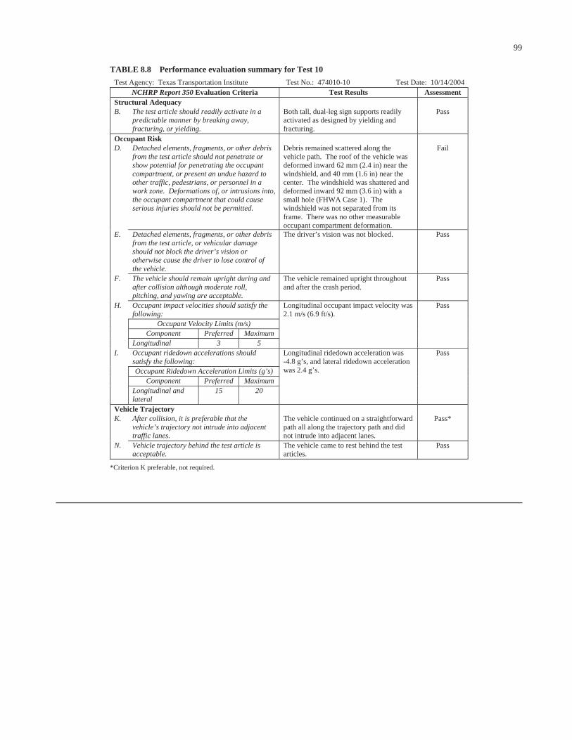
99
Test Agency: Texas Transportation Institute Test No.: 474010-10 Test Date: 10/14/2004NCHRP Report 350 Evaluation Criteria Test Results Assessment
Structural Adequacy B. The test article should readily activate in a
predictable manner by breaking away, fracturing, or yielding.
Both tall, dual-leg sign supports readily activated as designed by yielding and fracturing.
Pass
Occupant Risk D. Detached elements, fragments, or other debris
from the test article should not penetrate or show potential for penetrating the occupant compartment, or present an undue hazard to other traffic, pedestrians, or personnel in a work zone. Deformations of, or intrusions into, the occupant compartment that could cause serious injuries should not be permitted.
Debris remained scattered along the vehicle path. The roof of the vehicle was deformed inward 62 mm (2.4 in) near the windshield, and 40 mm (1.6 in) near the center. The windshield was shattered and deformed inward 92 mm (3.6 in) with a small hole (FHWA Case 1). The windshield was not separated from its frame. There was no other measurable occupant compartment deformation.
Fail
E. Detached elements, fragments, or other debris from the test article, or vehicular damage should not block the driver’s vision or otherwise cause the driver to lose control of the vehicle.
The driver’s vision was not blocked. Pass
F. The vehicle should remain upright during and after collision although moderate roll, pitching, and yawing are acceptable.
The vehicle remained upright throughout and after the crash period.
Pass
H. Occupant impact velocities should satisfy the following:
Occupant Velocity Limits (m/s)
Longitudinal occupant impact velocity was 2.1 m/s (6.9 ft/s).
Pass
Component Preferred Maximum Longitudinal 3 5
I. Occupant ridedown accelerations should satisfy the following:
Occupant Ridedown Acceleration Limits (g’s) Component Preferred Maximum Longitudinal and
lateral 15 20
Longitudinal ridedown acceleration was -4.8 g’s, and lateral ridedown acceleration was 2.4 g’s.
Pass
Vehicle Trajectory K. After collision, it is preferable that the
vehicle’s trajectory not intrude into adjacent traffic lanes.
The vehicle continued on a straightforward path all along the trajectory path and did not intrude into adjacent lanes.
Pass*
N. Vehicle trajectory behind the test article is acceptable.
The vehicle came to rest behind the test articles.
Pass
*Criterion K preferable, not required.
TABLE 8.8 Performance evaluation summary for Test 10

100
CHAPTER 9
FINDINGS AND RECOMMENDATIONS
The objective of this research was to develop nonpro-prietary, crashworthy work-zone traffic control devices con-structed of readily available materials. A state-of-the-practicereview helped identify sets of work-zone devices for whichadditional generic designs were needed. The sets for whichnew devices were developed include Type III barricadeswith attached sign panel; low-mounting-height (i.e., 0.3 m[1 ft]), portable sign supports with rigid sign substrate; andhigh-mounting-height (i.e., 1.5 m and 2.1 m [5 ft and 7 ft]),portable sign supports with rigid sign substrate. Numerousdesigns were developed for each of these sets. In additionto crashworthiness, consideration was given to cost andfunctionality (e.g., durability, handling, site adaptability,etc.) The designs were reviewed and prioritized by the pro-ject panel, and the prioritization served as the basis for thefull-scale crash testing. In addition to providing details ofthe crash-tested systems, this report presents a descriptionof the other design concepts for future consideration andtesting.
A total of 10 full-scale crash tests were conducted underthe project. The square, perforated steel tubing used to fabri-cate the framing of the various devices tested was manufac-tured from ASTM A570 grade 50 steel. The use of a rigidplywood sign substrate in each application presented a dis-tinct design challenge, but at least one design was success-fully crash tested in each set of work-zone devices investi-gated. Findings and recommendations resulting from thesetests are summarized in the following sections.
9.1 TYPE III BARRICADES WITH SIGNS
9.1.1 Perforated Steel-Tube Barricades
Based on successful test results for both centered (Test 1)and offset (Test 3) impact conditions, a perforated steel-tubebarricade with wooden rails and plywood sign panel is con-sidered to be an acceptable device for use in work zones. Botha 1.2-m × 1.2-m (4-ft × 4-ft) sign panel mounted at 1 ft in adiamond configuration and a 0.8-m × 1.5-m (2.5-ft × 5-ft) signpanel mounted at 0.8 m (2.5 ft) are considered acceptable foruse on this barricade frame. However, the taller 1.2-m × 1.2-m(4-ft × 4-ft) sign panel produced greater windshield damage.The measured windshield deformation for the perforated steel-
tube barricade with 1.2-m × 1.2-m (4-ft × 4-ft) sign panel was50 mm (2 in). The FHWA windshield damage classificationstates that “It is desirable that the maximum permanent de-flection of the windshield not exceed 55 mm (2.2 in). A max-imum permanent deflection exceeding 75 mm (3 in) shall beconsidered a failure.”
Plywood sign substrates were used in the crash testing ofperforated steel-tube barricades with attached sign panels.Because a plywood sign panel tends to be more critical froma crashworthiness standpoint because of its greater weight,the successful testing with a plywood substrate is consideredto be sufficient for acceptance of a similar design with a com-parably sized aluminum sign substrate or other lightweightsubstrate materials (e.g., corrugated plastic).
Because the wooden rails used in the successfully testedbarricades are considered more critical from an impact per-formance standpoint than lighter, hollow-profile plastic rails,both types of rails are considered acceptable. Wooden railsare often preferred for their low cost, availability, ease of fab-rication, and durability. Plastic rails are lighter in weight thanwood and, therefore, can make the barricade easier to handle.Because they do not fracture and break apart like woodenrails, plastic rails are sometimes reusable after an impact.Because the reflective sheeting adhered to the rails is a high-cost item, this reusability can make plastic rails more eco-nomical than wooden rails from a life-cycle cost standpoint.Additionally, plastic rails are available in white and do nothave to be painted as do wooden rails.
The use of the vertical braces in the barricade framing isoptional. The braces were incorporated into the crash-testedsystems because their presence represents a more criticalconfiguration for impact performance evaluation. In absenceof the vertical braces, the barricade rails and sign panel mustbe directly attached to the barricade uprights to prevent thesign and fractured rails from rotating into the windshield ofthe impacting vehicle. If the use of vertical braces is desiredto improve the constructability or functionality of the barri-cade, they can be fabricated from either square, perforatedtubing or 51-mm × 102-mm (2-in × 4-in) dimensional lum-ber. If the perforated steel-tube braces are used, the barricadecan be adjusted for placement on uneven terrain by extend-ing the height of one of the vertical braces relative to oneof the uprights. The braces are then bolted to the uprightsthrough existing holes in the perforated tubes. If the 51-mm

× 102-mm (2-in × 4-in) lumber braces (or no braces) areused, adjustability can be incorporated into the barricadethrough the use of taller sleeves and the extension of one ofthe uprights within its sleeve. Because the lumber braces arenot attached to the uprights, the sign panel must be attacheddirectly to the uprights.
The use of a Type A or C warning light with self-containedbattery compartment is considered acceptable for use withthis barricade design when attached to a perforated steel-tubeupright or perforated steel-tube vertical brace in a secure man-ner using a steel-plate connector (as tested) or other approvedattachment means. The warning light should be positionedsuch that the height of the light/lens is just above the top edgeof the upper barricade rail.
A horizontal brace should be incorporated into the designto help distribute the impact load to both uprights during anoffset impact. During the offset impact, the left side of the bar-ricade was being accelerated and rotated as a result of directcontact with the vehicle, while the right side of the barricaderemained relatively stationary and upright. This differentialmovement and rotation caused the barricade to twist and storeenergy. The buildup of internal energy eventually caused theconnection of the top rail and sign panel to the right uprightto fail. The released rail and sign panel subsequently “snapped”into the windshield of the vehicle, causing an unacceptablelevel of damage.
The extent to which this failure mode may apply to otherbarricade designs is unknown. Although barricades are oftenused in the field with lengths of 2.4 m (8 ft) or greater, theyare commonly crash tested with shorter lengths (e.g., 1.2 m[4 ft]) to enable the impacting vehicle to engage both sup-ports. While this condition is indeed critical for evaluatingrotation of the barricade components into the windshield, theoffset impact condition and resulting torsional failure modemay have been overlooked as another critical impact scenario.Because barricades in the field are more likely to be struck inan offset condition than directly along their centerline, thisimpact condition and failure mode may need to be more fullyexplored for barricades in general.
To address the problem observed in the offset test, a hori-zontal cross brace is added to the barricade to tie the twouprights together. The brace, fabricated from 38-mm (11⁄2-in)perforated steel tubing, is placed at a height of 457 mm (18 in)to engage the vehicle bumper. The objective behind the useof the brace is to help get the barricade moving together as aunit during an offset impact. Because of the low mountingheight, the addition of the horizontal brace should not influ-ence the impact performance for end-on impacts or centered,head-on impacts.
Recommended details of the perforated steel-tube Type IIIbarricade with 1.2-m × 1.2-m (4-ft × 4-ft) sign panel with a0.3-m (1-ft) mounting height are shown in Figure 9.1. Detailsof a corresponding design with a 1.5-m × 0.8-m (5-ft × 2.5-ft)sign panel mounted at a height of 0.8 m (2.5 ft) are shown inFigure 9.2.
101
9.1.2 Hollow-HDPE/Wooden Barricade
A barricade fabricated from wood and HPPL was found tohave acceptable impact performance in a full-scale crash test(Test 4). The 102-mm × 102-mm (4-in × 4-in) HPPL barri-cade uprights and vertical braces were manufactured fromHDPE. Both a 1.2-m × 1.2-m (4-ft × 4-ft) sign panel mountedat 0.3 m (1 ft) and a 0.8-m × 1.5-m (2.5-ft × 5-ft) sign panelmounted at 0.8 m (2.5 ft) are considered acceptable. However,the performance of the taller 1.2-m × 1.2-m (4-ft × 4-ft) signpanel is expected to be marginal.
A plywood sign substrate was used in the crash test of thehollow-HDPE/wooden barricade with attached sign panel.Because a plywood sign panel tends to be more critical froma crashworthiness standpoint because of its greater weight,the successful test with a plywood substrate is considered tobe sufficient for acceptance of a similar design with a com-parably sized aluminum sign substrate or other lightweightsubstrate materials (e.g., corrugated plastic).
Because the wooden rails used in the successfully testedbarricades are considered more critical from an impact per-formance standpoint than lighter, hollow-profile plastic rails,both types of rails are considered acceptable. A brief discus-sion of the advantages and disadvantages of each is providedin Section 9.1.1.
The use of the vertical braces in the barricade framing isoptional. They were incorporated into the crash-tested systembecause their presence represents a more critical configura-tion for impact performance evaluation. In absence of the ver-tical braces, the barricade rails and sign panel must be directlyattached to the barricade uprights to prevent the sign and frac-tured rails from rotating into the windshield of the impactingvehicle. If the HPPL braces are used, the barricade can be ad-justed for placement on uneven terrain by extending the heightof one of the vertical braces relative to one of the uprightsbefore bolting them together. Because the braces are attacheddirectly to the uprights, the sign panel need be attached onlyto the vertical braces and not directly to the uprights.
The use of a Type A or C warning light with self-containedbattery compartment is considered acceptable for use with thisbarricade design when attached to an HPPL upright or verti-cal brace in a secure manner using a steel-plate connector(as tested) or other approved attachment means. The warninglight should be positioned such that the height of the light/lensis just above the top edge of the upper barricade rail.
A horizontal brace should be incorporated into the designto help distribute the impact load to both uprights during anoffset impact. This design feature was added to address a fail-ure mode observed during the testing of the perforated steel-tube Type III barricade with sign panel.
Although the right-side door window was shattered by theend of the upper rail during the head-on, offset impact withthe hollow-HDPE/wooden barricade, the slight intrusion ofthe rail beyond the window was not considered to constitutea risk of serious injury in a frontal collision. This behaviorcan be mitigated by reducing the overhang distance of the

Figure 9.1. Details of the perforated steel-tube Type III barricade with sign panel mounted at a height of 0.3 m (1 ft).

Figure 9.2. Details of the perforated steel-tube Type III barricade with sign panel mounted at a height of 0.8 m (2.5 ft).

rails past the uprights. The spacing of the uprights is limitedby the width of the sign panel, which must be attached toeither the uprights or vertical braces. By increasing thespacing of the uprights from 1.4 m to 1.6 m (4 ft, 6 in to 5 ft,4 in), the overhang distance of the barricade rails is reducedfrom 0.5 m to 0.4 m (1 ft, 9 in to 1 ft, 4 in).
Recommended details of the hollow-HDPE/woodenType III barricade with 1.2-m × 1.2-m (4-ft × 4-ft) sign panelwith a 0.3 m (1 ft) mounting height are shown in Figure 9.3.Details of a similar design incorporating a 1.5-m × 0.8-m (5-ft× 2.5-ft) sign panel mounted at a height of 0.8 m (2.5 ft) areshown in Figure 9.4.
9.2 LOW-MOUNTING-HEIGHT SIGN SUPPORTS
Several low-mounting-height sign supports were designedfor use with rigid sign substrates mounted 0.3 m (1 ft) aboveground. The designs were prioritized by the panel based onconsiderations such as cost, ease of fabrication, functionality,stability, etc. The three designs receiving the highest prioritywere evaluated through full-scale crash testing. All threedesigns were fabricated from square, perforated steel tubing.
A plywood sign substrate was used in each crash test. Be-cause its greater weight tends to make a plywood sign panelmore critical from a crashworthiness standpoint, the sign sup-ports successfully tested with a plywood substrate are alsoconsidered to be acceptable when used with a comparablysized aluminum sign substrate or other lightweight substratematerials (e.g., corrugated plastic).
9.2.1 Adjustable Tripod
The adjustable tripod system (Test 5) produced the leastamount of damage to the vehicle. Damage to the windshieldwas limited to a small crack, and the driver’s view was notobstructed by the sign panel or windshield damage.
One of the variables related to the tripod design that canaffect both impact performance and functionality is the tiltangle of the sign panel. A greater tilt angle makes the systemless prone to rotate back into the windshield and will give itmore stability against overturn due to wind. However, thelegibility of the sign may be compromised if the tilt anglebecomes too large. For the crash test, the tilt angle of the signpanel was set at 30 degrees from vertical. This tilt angle shouldprovide a visible, legible sign in both daytime and nighttimeconditions. The good impact performance achieved with thissystem is attributed in large part to the 30-degree lay backangle of the sign. While the crash performance indicates somedeviation from this angle would be tolerable, the role of the tiltangle in achieving acceptable impact performance should beproperly noted and considered during implementation.
In addition to good stability, this design has good adjusta-bility in all directions. Side-to-side adjustment for accommo-dating placement on roadside slopes is achieved by telescop-ing one or both of the front legs as needed. Fabrication of the
104
system can be simplified by making one or both of the frontlegs out of a single piece of tubing. However, if both legs arecontinuous, side-to-side adjustment is sacrificed. If needed,front-to-back adjustment for accommodating placement onvertical grades is achieved by adjusting the attachment pointof the strut to the rear leg. Unbolting the strut from the rearleg allows the unit to be folded flat for easy transportation.
Use of the cross bar at the bottom of the rear leg is optional.The cross bar can be used to provide a means of ballasting thesystem with sandbags if desired. The cross bar is bolted to thebottom of the rear leg with a single bolt. The cross bar canthen rotate as needed to accommodate placement of the sys-tem on a roadside slope. If additional ballast is desired in highwind-speed locations, cross bars can also be added to the frontlegs of the tripod frame.
Details of the adjustable tripod sign support are shown inFigure 9.5.
9.2.2 Pivoting Dual Uprights
The sign support system with pivoting dual uprights (Test 6)deformed the windshield to classify its performance as mar-ginal. The windshield was shattered and deformed inward60 mm (2.3 in). The FHWA windshield damage classifica-tion guidelines state that “It is desirable that the maximumpermanent deflection of the windshield not exceed 55 mm(2.2 in). A maximum permanent deflection exceeding 75 mm(3 in) shall be considered a failure.”
The sign support system is considered acceptable for use.Although the sign panel briefly obscured the driver’s vision,the 0.043 s interval during which the panel substantially cov-ered the windshield is not considered to be of long enoughduration to adversely influence the driver’s ability to controlthe vehicle.
Side-to-side adjustment of the sign support system to accom-modate placement on roadside slopes is achieved by extend-ing the upright on the downhill side of the slope the desireddistance out of its sleeve or adjusting the attachment of oneof the uprights to the sign panel. To tilt the sign panel to thefront or back to accommodate placement on vertical grades,the upper bolt used to connect the sleeve to the pivot plate isremoved and reinserted after aligning the sleeve with one ofthe other holes in the plate.
The top adjusting bolt on each plate can be removed to foldthe sign down for easy transport as a single unit. This processcan be further simplified by using a pin rather than a bolt atthis upper connection point on the pivot plate. If desired (forease of repair, etc.), the sign panel and uprights can be read-ily detached from the base by removing the bolts that attachthe uprights inside the sleeves.
If front-to-back adjustment is neither needed nor desired,fabrication of the pivot plate can be simplified by using onlytwo holes—one in the center of the plate and one at the topedge. This simplification eliminates the angle adjustment ofthe uprights, but retains the ability to readily fold the systemdown for transport. The absence of the additional holes in the

Figure 9.3. Details of the hollow-HDPE/wooden Type III barricade with sign panel mounted at a height of 0.3 m (1 ft).
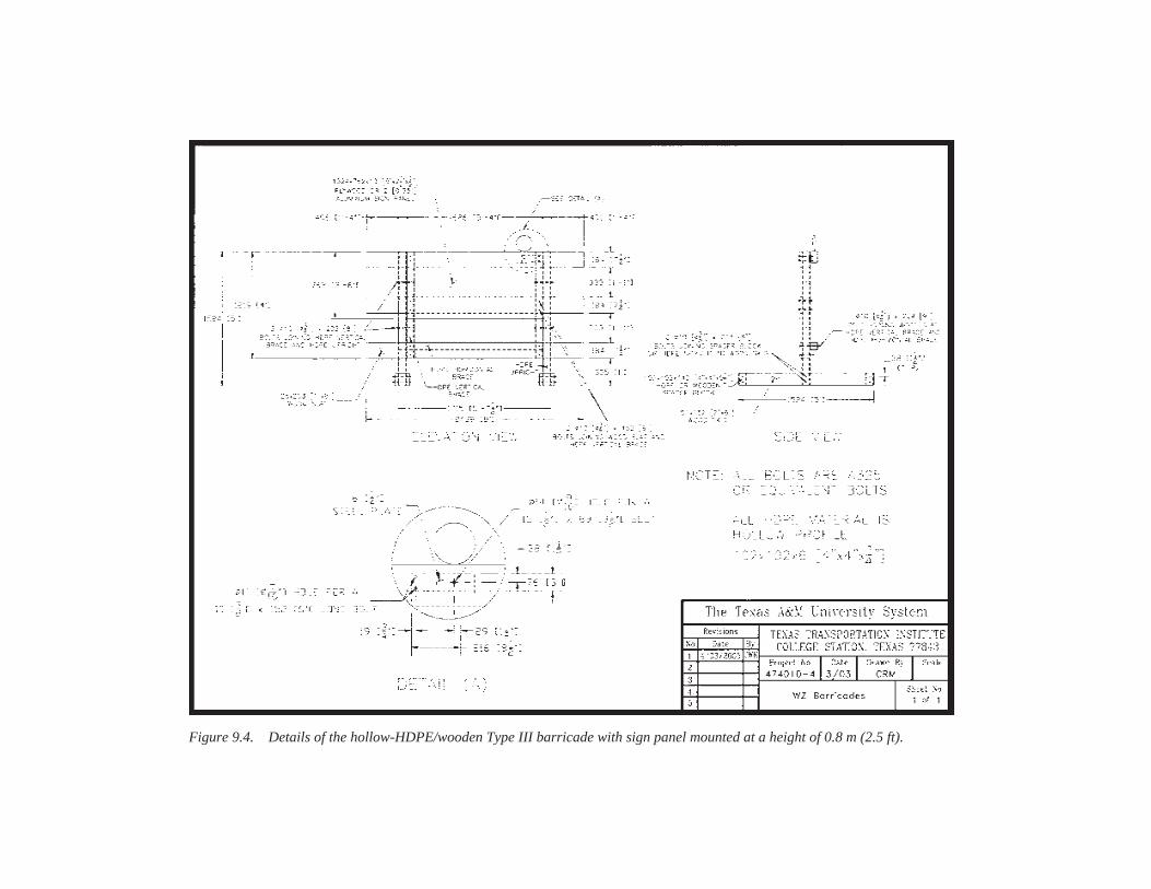
Figure 9.4. Details of the hollow-HDPE/wooden Type III barricade with sign panel mounted at a height of 0.8 m (2.5 ft).
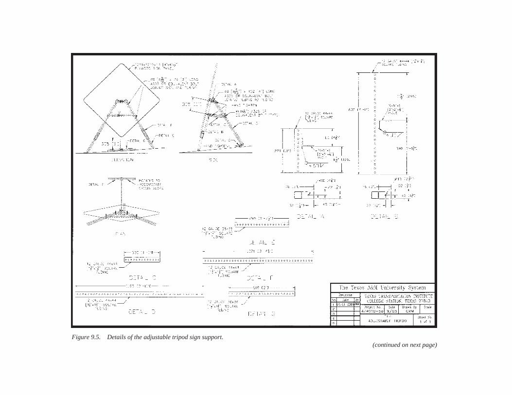
Figure 9.5. Details of the adjustable tripod sign support.(continued on next page)

Figure 9.5. (Continued)

pivot plate will not affect the impact performance of the sys-tem. If desired, the pivot plates can be welded rather thanbolted to the skids. This alternative fabrication method shouldnot adversely affect impact performance.
Details of the sign support system with pivoting dual up-rights are shown in Figure 9.6.
9.2.3 Independent Dual Uprights
The sign support system with independent dual uprights(Test 7) is the simplest and least expensive of the low-mounting-height sign support systems designed or testedunder this project. The system comprises two identical, inde-pendent uprights that, when bolted to their respective skids,form inverted, T-shaped legs. The sign panel is bolted to theuprights and serves as the cross bracing for the system.
The impact performance of the system is considered accept-able and the system is deemed suitable for use in work zones.Although the sign panel briefly covered the windshield dur-ing the test, the 0.06-s interval during which the driver’svision would have been obscured is not considered to be oflong enough duration to adversely influence the driver’s abil-ity to control the vehicle.
Side-to-side adjustability to accommodate placement ofthe sign support on a roadside slope is achieved by extend-ing the downhill upright out of its sleeve. Transportation isfacilitated by the removal of the bolts or pins connecting theuprights inside the sleeves. Although the ability may not beneeded, the system does not adjust front to back to accom-modate vertical grade.
In the opinion of the researchers, the addition of a horizon-tal cross brace for added stability should not adversely affectthe impact performance of this low-mounting-height sign sup-port system if the cross brace is placed across the sleeves at ornear the skids.
Details of the sign support system with independent dualuprights are shown in Figure 9.7.
9.3 HIGH-MOUNTING-HEIGHT SIGN SUPPORTS
Several high-mounting-height sign supports were designedfor use with rigid sign substrates mounted 1.5 m to 2.1 m (5 ftto 7 ft) above ground. The designs were prioritized by thepanel based on considerations such as cost, ease of fabrication,functionality, stability, etc. The three designs receiving thehighest priority were evaluated through full-scale crash test-ing. All three designs were fabricated from square, perforatedsteel tubing. Findings and recommendations regarding thehigh-mounting-height sign supports evaluated under the proj-ect are summarized in the following subsections.
9.3.1 Dual Uprights with Slip Connection
This sign support system was considered to be the smallest,lightest, and least expensive dual-support system fabricated
109
from square, perforated steel tubing that can resist the selected72-km/h (45-mi/h) design wind speed for a 1.2-m × 1.2-m(4-ft × 4-ft) sign panel mounted at a height of 1.5 m to 2.1 m(5 ft to 7 ft). Impact performance of similar designs was un-acceptable when the uprights were bolted inside their respec-tive sleeves. The tested design incorporated a short sleeve andunbolted connection as a slip mechanism intended to permitrelease of the uprights from their skids before substantial plas-tic deformation was experienced. However, the relativelylight 44-mm (13⁄4-in), 14-gauge perforated steel-tube uprightsstill deformed around the front of the impacting vehicle beforereleasing from the sleeves. This behavior resulted in the up-rights and sign panel contacting the windshield and roof of thevehicle with sufficient force to induce an unacceptable levelof damage. With the windshield dislodged and torn, and theroof deformed downward into the occupant compartment200 mm (7.9 in), the system failed the test.
Because the most economical design did not perform sat-isfactorily, the uprights needed to be strengthened and/oralternative release mechanisms evaluated with the intent oflimiting the amount of deformation to the uprights. Limitingupright deformation, in turn, would reduce the rotational velo-city of the sign panel and decrease the contact forces betweenthe sign panel and vehicle windshield.
9.3.2 Dual Uprights with Raised Slip Joint
A potential solution to the failure observed with the high-mounting-height sign support system with slip connectionwas a dual-upright sign support system with raised slip joint.In this design, the length of the sleeve was extended and theslip connection between the uprights and sleeves was effec-tively raised from near ground level to above bumper height.In theory, activation of the slip joint during impact would re-sult in a higher point of rotation of the uprights and sign panelafter their release, which would help reduce the probabilityof secondary contact between the sign panel and windshieldof the impacting vehicle.
Such behavior was observed in the 0-degree impact, andcontact between the sign panel and vehicle was avoided. How-ever, in the 90-degree impact, the deformation of the sleevesgenerated rotation of the sign panel into the vehicle before therelease of the uprights from the sleeves, and the subsequentcontact between the sign panel and vehicle windshield re-sulted in an unacceptable level of damage. With a small holein the windshield and permanent deformation of the wind-shield of 92 mm (3.6 in), the system was considered to havefailed the test.
9.3.3 Strong Dual Uprights with Slip Connection
The high-mounting-height sign support system with strong,dual uprights is a variation of the slip connection conceptthat incorporates larger, stronger sections of perforated steeltubing. Uprights of 57-mm (21⁄4-in) square, perforated steel

Figure 9.6. Details of the sign support system with pivoting dual uprights.
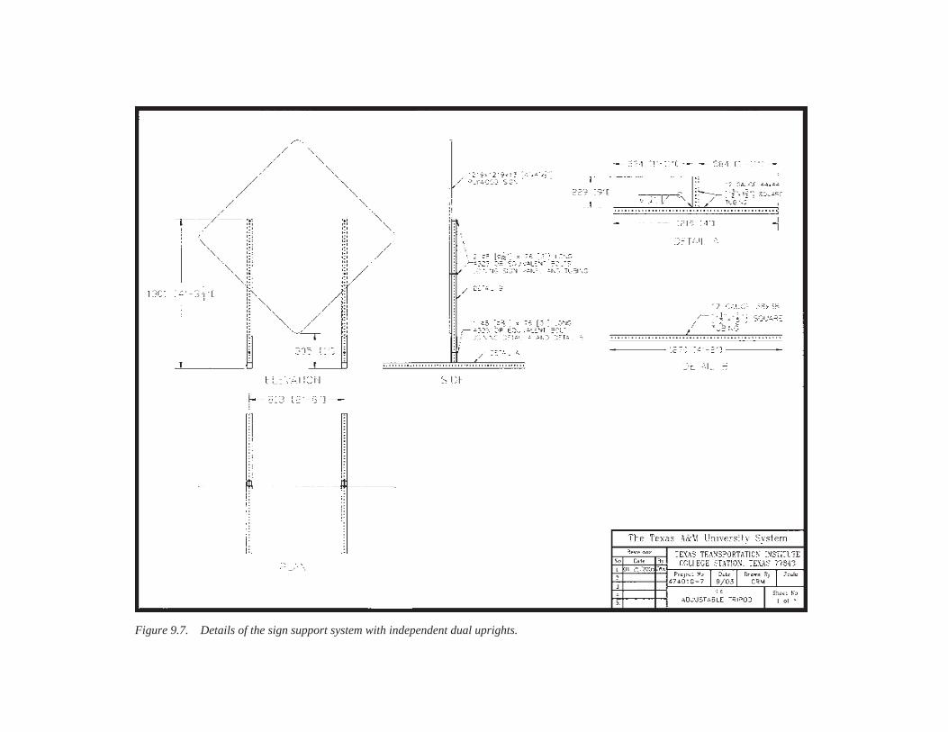
Figure 9.7. Details of the sign support system with independent dual uprights.

tubing are inserted into 64-mm (21⁄2-in) square, perforatedsteel sleeves. In theory, the increased flexural strength ofthe larger uprights would reduce the deformation of theuprights around the front of the vehicle before they releasedfrom the sleeves, thus improving the likelihood that the sys-tem would meet crash-test requirements.
The strong, dual-upright perforated steel-tube sign supportwith 1.2-m × 1.2-m × 13-mm (4-ft × 4-ft × 1⁄2-in) plywoodsign panel mounted at a height of 1.5 m (5 ft) met all requiredevaluation criteria for both the head-on and end-on impactscenarios. The incorporation of larger, stronger uprights intothe design limited the deformation of the uprights and pre-vented them from wrapping around the front of the vehicle.The point of rotation changed from bumper height (i.e., approx-imately 457 mm [18 in] above ground) to a point that closelycoincides with the overall center of mass of the sign supportsystem. In addition to raising the point of rotation, the strongeruprights also effectively decreased the rotational velocity.These factors combined to reduce the severity of the second-ary impact of the support structure with the windshield androof of the vehicle, thus limiting the extent of vehicle defor-mation to an acceptable level.
Using larger tubular members to achieve acceptable impactperformance increases the system’s weight and cost of fabri-cation. The increased weight will make the sign support sys-tem more difficult to handle.
The 1.5-m (5-ft) mounting height is generally believed tobe more critical than a 2.1-m (7-ft) mounting height from animpact performance standpoint, because the lower center ofmass decreases the point of rotation of the supports and in-creases rotational velocity. These factors combine to increasethe severity of secondary impacts of the supports and signpanel with the windshield and roof of the impacting vehicle.Since the strong, dual-upright sign support system met all re-quired evaluation criteria with the sign panel mounted at 1.5 m(5 ft), the researchers consider the same sign support systemto be acceptable for a 2.1-m (7-ft) mounting height.
As discussed previously, the rigidity and mass of a ply-wood sign panel make plywood more critical than most othersubstrate materials from a crashworthiness standpoint. Be-cause of the greater weight of plywood, the successful test ofthe strong, dual-upright sign support system with a plywoodsubstrate is considered to be sufficient to indicate acceptableimpact performance of the same sign support system with acomparably sized aluminum sign substrate or lighter weightcorrugated plastic sign substrate.
During analysis of the high-speed film of the test, the slipmechanism was observed not to activate as designed. Uponimpact, the sign support system moved as a unit. The uprightsremained inside the sleeves until well after momentum wastransferred to the entire system. This behavior indicates thatthe slip mechanism did not affect the impact response of thesystem; as a result, a longer sleeve (e.g., 152 mm to 229 mm[6 in to 9 in]) can be used without adversely affecting impactperformance. For the same reasons, the researchers have con-
112
cluded that bolting or pinning the uprights inside the sleeveswould not compromise impact performance. Such designmodifications would provide better adjustability to accom-modate placement of the sign support on a roadside slope bypermitting the length of the downhill upright to be extendedwithin the sleeve. Although not considered to be a problemin the test, bolting of the uprights inside the sleeves wouldpermit the system to travel as a unit and reduce any potentialdebris hazard associated with the skids releasing from theuprights.
Recommended details of the strong, dual-upright signsupport system are shown in Figure 9.8 and Figure 9.9 fora 1.5-m (5-ft) sign panel mounting height and 2.1-m (7-ft)sign panel mounting height, respectively. These drawingsincorporate some of the changes suggested by the researchersand vary from the tested configuration.
9.3.4 Additional Designs
Another means of increasing the flexural strength of theuprights to reduce deformation during impact is to nest twosmaller sections of perforated steel tubing inside each otherto form a stronger composite section. When finalizing the de-sign details for such a system for consideration under thisproject, the researchers learned that a similar system had beensuccessfully crash tested for the Michigan DOT. (16) In thisdesign, 44-mm (13⁄4-in) square, perforated steel-tube uprightsnest within 51-mm (2-in) square tubes. The tops of the nestedportions extend 1067 mm (42 in) above ground. The bottomsof the nested uprights extend below the ends of the 51-mm(2-in) square tubes and are inserted into 152-mm (6-in) longsleeves. The sleeves and skids are fabricated from 51-mm(2-in) square, perforated steel tubing. The system was testedwith a 1.2-m × 1.2-m (4-ft × 4-ft) plywood sign panel at amounting height of 1.5 m (5 ft).
Another high-mounting-height sign support system usingnested uprights was successfully crash tested concurrent withthose being tested under this project. (17) In this design, a1.2-m (4-ft) long vertical sleeve fabricated from 51-mm (2-in)square, 12-gauge perforated steel tubing was welded to thecenter of a 1.5-m (5-ft) long skid fabricated from the samematerial using two lines of weld parallel to the length ofthe skid along the inside and outside edges of the sleeve. Thesleeves were not welded to the skids along their front or backedges. A 44-mm × 44-mm × 3.4-m (13⁄4-in × 13⁄4-in × 11-ft),12-gauge perforated steel upright was inserted into the sleeveuntil it rested on a bolt passing through the bottom of thesleeve. The system was tested with a 1.2-m × 1.2-m × 10-mm(4-ft × 4-ft × 3⁄8-in) corrugated plastic sign panel attached tothe vertical supports in a diamond configuration at a mount-ing height of 2.1 m (7 ft) above ground. The sign substrateand mounting height for this system should not be changedunless further testing is conducted to demonstrate acceptableperformance.
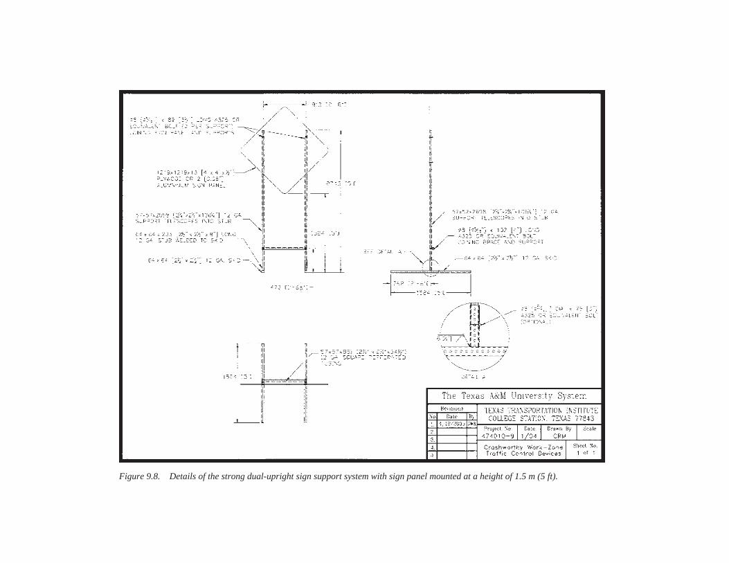
Figure 9.8. Details of the strong dual-upright sign support system with sign panel mounted at a height of 1.5 m (5 ft).

Figure 9.9. Details of the strong dual-upright sign support system with sign panel mounted at a height of 2.1 m (7 ft).
These two systems are briefly described and referenced toinform the reader of their availability for use in work zones.These systems—together with the barricades with signs, low-mounting-height sign supports, and high-mounting-height signsupports successfully crash tested under this project—will pro-vide user agencies with more generic, crashworthy design alter-natives to use for traffic control in their work-zone operations.
9.4 FUNCTIONALITY
A rating scheme was developed to assist with the compar-ative evaluation of the functional performance of variouswork-zone traffic control devices in the following categories:wind resistance, durability, handling, fabrication/repair, andsite adaptability. The rating scale for each category includes“high,” “average,” and “low.” A discussion of each categoryand its associated rating scale is presented in Section 4.2.5,Functional Performance Rating.
The overall functionality of a device is assessed by aver-aging the wind resistance, durability, handling, fabrication/repair, and site-adaptability ratings. This rating scheme wasused to assess the relative functionality of the various work-zone traffic control devices successfully developed and crashtested under this project to assist user agencies with deviceselection. The results of this assessment are presented inTable 9.1.
The low level of distinction among the ratings assigned tothe various work-zone devices is not surprising. Indeed, theobjective of the project was to develop crashworthy work-zone devices that can be fabricated from readily availablematerials and that possess a high degree of functionality. Thus,
115
the various aspects of functionality were considered duringthe design process. If this rating scheme were applied to otherexisting devices, the range of the individual and overall ratingswould vary more widely.
The assessment of functional performance is somewhat sub-jective and relative in nature and reflects the opinions of theresearchers. User agencies may have different opinions regard-ing the assigned functionality ratings and/or give more weightto other criteria (e.g., cost) when deciding among these devices.
Experience with full-scale crash testing of work-zone traf-fic control devices suggests that the impact performance ofmost devices is not very sensitive to the amount of ballastapplied to the base. Sandbags are readily ripped open duringan impact, thus dispersing the sand. Any amount of ballastthat can be practically applied to the base of a device is notlikely to adversely affect its impact performance. However,even if the device is adequately designed and has a “high”wind rating, insufficient ballast can increase the probabilityof a device overturning during windy conditions. The amountof ballast (e.g., number of sandbags) required to prevent over-turn of a barricade or sign support system varies dependingon the selected design wind speed and characteristics of thedesign such as size of the sign panel and mounting height ofthe sign and/or rails. Guidance on the amount of ballastrequired for different design wind speeds is provided in Sec-tion 8.1, Wind Load Analysis.
The devices developed under this project are not onlycrashworthy, but also considered to provide a high degree ofpracticality and functionality. These devices provide useragencies with additional alternatives for relaying informationand controlling traffic in work zones.
Device Description Functional Performance*
Figure No. Frame Rails Sign Bracing
Wind Resist. Durability Handling
Fabricate/ Repair
Site Adapt.
OverallRating
Barricades with Signs
9.1, 9.2 Perforated
steel Wood or plastic
Wood or aluminum
Wood or perforated
steel High High High High High High
9.3, 9.4 HPPL Wood or plastic
Wood or aluminum
HPPL High Average Average High Average Average
Low-Mounting-Height Sign Supports
9.5 Perforated
steel N.A.
Wood or aluminum
Perforated steel
Average High High Average High High
9.6 Perforated
steel N.A.
Wood or aluminum
N.A. High High High Average High High
9.7 Perforated
steel N.A.
Wood or aluminum
N.A. High High Average High High High
High-Mounting-Height Sign Supports
9.8, 9.9 Perforated
steel N.A.
Wood or aluminum
Perforated steel
High High Average High Average High
* See Section 4.2.5, Functional Performance Rating, for description of rating categories and scale.
TABLE 9.1 Functional assessment of successfully tested work-zone devices
116
REFERENCES
1. H. E. Ross, Jr., D. L. Sicking, R. A. Zimmer, and J. D. Michie.NCHRP Report 350: Recommended Procedures for the SafetyPerformance Evaluation of Highway Features, TRB, NationalResearch Council, Washington, D.C., 1993.
2. FHWA. “Part VI: Standards and Guides for Traffic Controlsfor Street and Highway Construction, Maintenance, Utilityand Incident Management Operations.” In Manual on Uni-form Traffic Control Devices, 1988 Edition, Revision 3, Sep-tember 1993.
3. K. K. Mak, R. P. Bligh, and W. L. Menges. “Evaluation of WorkZone Barricades and Temporary Sign Supports,” ResearchReport 5388-1F, Texas Transportation Institute, College Station,TX, February 1996.
4. K. K. Mak, R. P. Bligh, and W. L. Menges. “Evaluation ofWork Zone Barricades,” Research Report 3910-S, TexasTransportation Institute, College Station, TX, October 1997.
5. K. K. Mak, R. P. Bligh, and W. L. Menges. “Evaluation ofSign Substrates for Use with Plastic Drums,” Research Report2924-3F, prepared for Texas Department of Transportation,Austin, TX, October 1996.
6. K. K. Mak and R. A. Zimmer. “Evaluation of Plastic DrumSpecifications,” Research Report 2924-2F, prepared for TexasDepartment of Transportation, Austin, TX, September 1995.
7. K. K. Mak, R. A. Zimmer, and W. L. Campise. “Testing andEvaluation of Work Zone Traffic Control Devices,” ResearchReport 1938-1F, prepared for Texas State Department of High-ways and Public Transportation, Austin, TX, November 1991.
8. K. K. Mak and W. L. Campise. “Testing and Evaluation ofWork-Zone Traffic Control Devices,” Research Report 1917-1F,prepared for Texas State Department of Highways and PublicTransportation, Austin, TX, October 1990.
9. R. P. Bligh, K. K. Mak, and L. R. Rhodes, Jr. “Crash Testing andEvaluation of Work Zone Barricades,” Transportation Research
Record 1650, TRB, National Research Council, Washington,D.C., 1998, pp. 36–44.
10. K. K. Mak, R. P. Bligh, and L. R. Rhodes, Jr. “Crash Testingand Evaluation of Work Zone Traffic Control Devices,” Trans-portation Research Record 1650, TRB, National ResearchCouncil, Washington, D.C., 1998, pp. 45–54.
11. R. P. Bligh, D. L. Bullard, W. L. Menges, and S. K. Schoeneman.“Impact Performance Evaluation of Work Zone Traffic ControlDevices,” Research Report 1792-2, Texas Transportation Insti-tute, College Station, TX, 2000.
12. K. K. Mak, W. L. Menges, and S. K. Schoeneman. Project RF473220-13: NCHRP Report 350 Test 3-71 of Lang ProductsCrosswind™ Portable Sign Support, Texas Transportation Insti-tute, College Station, TX, November 1999.
13. AASHTO. Standard Specifications for Structural Supports forHighway Signs, Luminaires, and Traffic Signals, 3rd Edition,Washington, D.C., 2001.
14. R. P. Bligh. “Determining Design Wind Loads for Work ZoneTraffic-Control Devices,” Transportation Research Record:Journal of the Transportation Research Board, 1877, Trans-portation Research Board of the National Academies, Wash-ington, D.C., 2004, pp. 117–125.
15. American Society of Civil Engineers (ASCE). Minimum DesignLoads for Buildings and Other Structures, Standard 7-95, 1996.
16. K. A. Polivka, R. K. Faller, J. C. Holloway, J. R. Rohde, andD. L. Sicking. “Safety Performance Evaluation of Michigan’sTraffic Control Devices,” Research Report TRP-03-128-02,Midwest Roadside Safety Facility, Lincoln, NE, 2003.
17. R. P. Bligh, W. L. Menges, and R. R. Haug. “NCHRP Report 350Test 3-71 of Allied Tube & Conduit Dual-Leg PerforatedSquare Steel Tube Temporary Sign Support,” Research ReportNo. 400001-ATC1, Texas Transportation Institute, College Sta-tion, TX, December 2004.

117
APPENDIX A
FHWA WINDSHIELD DAMAGE CLASSIFICATION
WINDSHIELD DAMAGE FOR CATEGORY 2WORK ZONE TRAFFIC CONTROL DEVICES:
Draft Guidance for Pass / Fail
Safety glass used in vehicle windshields has been designedas a laminated system to resist penetration. A windshield canwithstand a severe blow and show extensive cracking, yetprotect the occupants by resisting penetration by all or partsof the test article. Crash records are not sufficiently detailedto tell us how the damage to a windshield relates to the sever-ity of a crash. However there is a need to be able to evaluatevarious safety features by observing the results of crash tests.
Report 350 states:
Detached elements, fragments or other debris from the testarticle should not penetrate or show potential for penetratingthe occupant compartment, or present an undue hazard toother traffic, pedestrians, or personnel in a work zone. Defor-mations of, or intrusions into, the occupant compartment thatcould cause serious injuries should not be permitted.
This provision has been interpreted in different ways bythe crash test agencies when evaluating windshield damageresulting from tests with category 2 work zone devices. Themost conservative evaluations have failed a device when thecracking extended to the inner layer of glass. The most lib-eral interpretation considered the test article acceptable evenwhen the entire windshield was shattered sending glass par-ticles into the occupant compartment, as long as the test arti-cle itself did not penetrate the windshield. The ability of thedriver to see through the damaged windshield also must beconsidered. An informal survey conducted during the Trans-portation Research Board’s meetings of January, 1999, showeda similar diversity of opinion among researchers, manufac-turers, and users of the devices.
In FHWA’s July 25, 1997, memorandum, it was suggestedthat windshield damage and intrusion each be rated on ascale. Those scales did not classify the damage as passing orfailing. Based upon full-scale crash testing FHWA has re-viewed subsequent to that memorandum, the following sevenclasses of damage are offered as a guideline for evaluatingwindshield damage. It is realized that there is still room forinterpretation between these classes, but that some measureof consistency will be introduced. Sketches are included asan aid in describing the damage and assessing the results.
Please note that the amount and extent of cracking shown inthe sketches is far less than will be seen in a real windshield.
Case 1. Fail: Any impact that causes a hole through thewindshield glass whether or not part of the test articleenters the occupant compartment.
Case 2. Fail: Any impact that destroys or deforms thewindshield to the extent that it separates from the frame.
Case 3. Fail: Any impact where the windshield is crackedoverall to such a degree that the driver cannot readilysee to navigate.
Case 4. Pass: Any impact where the windshield is crackedoverall and the windshield deflects in towards the occu-pants without causing a hole in the plastic layer. Glassparticles from the inner layer of glass are permitted inthe passenger compartment. The driver can still readilysee through the damage and bring the vehicle to a safestop. (One test house uses a criterion of 2-inch maxi-mum permanent deflection of the windshield as a pass/fail measure.)
Case 5. Pass: An impact that causes a roughly circular areaof localized cracking / shattering completely obscuringvision to a diameter of no greater than one foot. No pen-etration of the test article through the glass occurs. Ex-tensive cracking throughout the remainder of the wind-shield is permitted but no deformation occurs other thanat the point(s) of impact.
Case 6. Pass: An impact on the roof line that causes shat-tering of the windshield near the point of impact and/orother cracking that extends throughout the windshield.(This is primarily for taller devices that “bridge” betweenthe front of the hood and the roof.)
Case 7. Pass: An impact that causes only minor crackingor dings on the windshield. (Not illustrated.)
The NCHRP committee pursuing the next generation crashtest guidance should consider guidelines for evaluating passen-ger compartment intrusion. These seven criteria may be used asa starting point for windshield damage. FHWA solicits com-ments from all concerned as to the appropriateness of these cri-teria, both in terms of measuring windshield damage usingthese seven classes, and in terms of expected injury severity inreal-world crashes. Please contact Mr. Nicholas Artimovich ofthe Office of Highway Safety Infrastructure with comments orquestions regarding these guidelines at (202) 366-1331 or viaE-mail at [email protected].

118
Case 1: Impact causes a hole in the windshield.
Fail
Case 2: Impact causes separation of windshield from frame.
Fail
Case 3: Significant overall damage. Driver cannot readily see ahead tonavigate to a safe stop.
Fail
Case 4: Significant overall damage but no hole. Driver can readily see tobring the vehicle to a safe stop.
Pass (Maximum permanent deflection criteria may apply)
Case 5: Significant local damage but no hole.
Pass
Case 6: Significant damage where test object struck roof line but caused nopenetration of windshield nor separation of windshield from roof.
Pass
[The black areas above indicate extensive damage to the glass restricting visibility, and some deflection of the windshieldinward. The white dot in Case 1 indicates a hole. The white area at the top of case 2 indicates separation of the windshieldfrom the frame.]

119
APPENDIXES B THROUGH F
Appendixes B through F are available from TRB uponrequest.

Abbreviations used without definitions in TRB publications:
AASHO American Association of State Highway OfficialsAASHTO American Association of State Highway and Transportation OfficialsADA Americans with Disabilities ActAPTA American Public Transportation AssociationASCE American Society of Civil EngineersASME American Society of Mechanical EngineersASTM American Society for Testing and MaterialsATA American Trucking AssociationsCTAA Community Transportation Association of AmericaCTBSSP Commercial Truck and Bus Safety Synthesis ProgramDHS Department of Homeland SecurityDOE Department of EnergyEPA Environmental Protection AgencyFAA Federal Aviation AdministrationFHWA Federal Highway AdministrationFMCSA Federal Motor Carrier Safety AdministrationFRA Federal Railroad AdministrationFTA Federal Transit AdministrationIEEE Institute of Electrical and Electronics EngineersISTEA Intermodal Surface Transportation Efficiency Act of 1991ITE Institute of Transportation EngineersNASA National Aeronautics and Space AdministrationNCHRP National Cooperative Highway Research ProgramNCTRP National Cooperative Transit Research and Development ProgramNHTSA National Highway Traffic Safety AdministrationNTSB National Transportation Safety BoardSAE Society of Automotive EngineersSAFETEA-LU Safe, Accountable, Flexible, Efficient Transportation Equity Act: A Legacy for Users (2005)TCRP Transit Cooperative Research ProgramTEA-21 Transportation Equity Act for the 21st Century (1998)TRB Transportation Research BoardTSA Transportation Security AdministrationU.S.DOT United States Department of Transportation