Embed Size (px)
Citation preview

NCDA Design Final Report
Team 7: Silo PackerTASA Engineering
Design Engineers:
Adel Abumohor – [email protected] Acheson – [email protected]
Pete Sullivan – [email protected]. Michael Tate – [email protected]
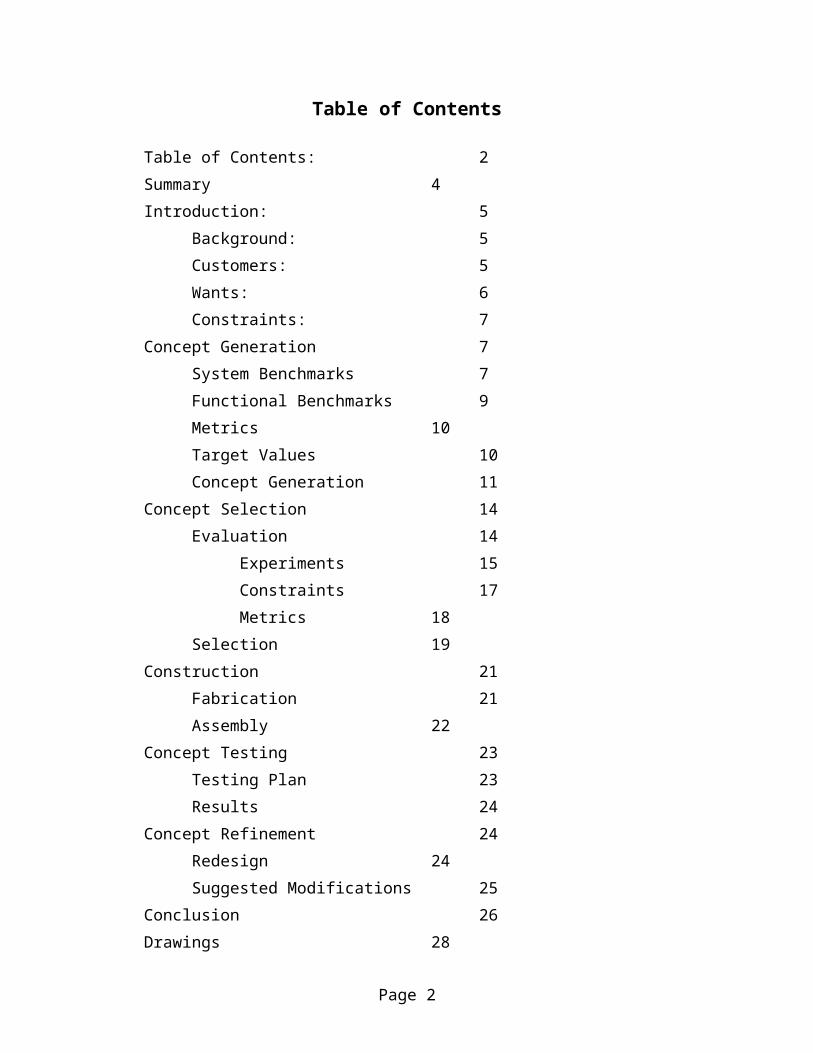
Table of Contents
Table of Contents: 2Summary 4Introduction: 5
Background: 5Customers: 5Wants: 6Constraints: 7
Concept Generation 7System Benchmarks 7Functional Benchmarks 9Metrics 10Target Values 10Concept Generation 11
Concept Selection 14Evaluation 14
Experiments 15Constraints 17Metrics 18
Selection 19Construction 21
Fabrication 21Assembly 22
Concept Testing 23Testing Plan 23Results 24
Concept Refinement 24Redesign 24Suggested Modifications 25
Conclusion 26Drawings 28Budget 41Sketches 42
Page 2

Executive Summary:
TASA was commissioned to design and build a prototype test silo loader for Dr. Limin
Kung of the University of Delaware Agricultural Department. Agricultural researchers use
apparatus like these to fill small test silos in order to model how different bacterial and chemical
agents inhibit the spoilage of silage materials. Dr. Kung is one of a list of seven customers, all
related to agriculture, that come from both academic and commercial fields and are involved in
research similar to that done at UD. These customers desire an apparatus which can allow them
to pack a test silo quickly and easily, but with high accuracy and precision. This apparatus must
beat their current method of packing and meet storage requirements and a very small budget.
We began addressing the problem by benchmarking various systems that are listed in
Table 2 of the report. We broke our design into different functions like compacting devices and
pressure sensors and determined which items were the best in their particular area. In order to
evaluate our benchmarks and also our own designs we distilled the customers wants into a list of
ten metrics found in Table 3. We proposed targets from our benchmarking and determined
which metrics were critical to our design and which were only peripheral to it.
We created concepts using our benchmarking as a foundation for ideas, but also reaching
beyond it for new and interesting concepts that may give us an edge on the competition. Our
concepts were grouped into four families of related ideas; extruders, horizontal pistons, vertical
pistons, and the “other” group.
We performed a series of experiments in order to test basic concepts used in all our
designs and to also determine some basic silage properties. We eliminated some designs because
their costs exceeded our budget limit. We ranked the concepts that were left against our critical
metrics in order to get a rough comparison and then did a complete ranking of the front-runners
Page 3

in order to determine which concept was truly the best analytically. We took our best design, a
vertical pneumatic piston, and designed its various parts.
We fabricated a prototype from these parts designs and then created a testing procedure
for this prototype. Using the results from the testing procedure in order to chart its performance
within our metrics. We evaluated the prototype’s performance against the target values set by
the metrics and made minor redesigns to specific areas. We also showed the original prototype
to Dr. Kung, who had some of his own comments.
We then slightly redesigned and rebuilt the prototype into order to increase the design’s
performance in several metrics and in order to create a safer final product. The end result is the
final prototype which was presented on Friday, April 23.
Introduction:
Background:
TASA was commissioned to design and build a prototype test silo loader for Dr. Limin
Kung of the University of Delaware Agricultural Department.
Silos are widespread in agricultural use to store livestock feed due to their low cost and
simple design. The basic concept behind the silage process is that bacteria use up all the oxygen
in the silo and so the silage material (the material which is packed inside the silo) doesn’t spoil
for extended periods as long as no oxygen is allowed to enter the storage system.
Due to its widespread use in agriculture, there is a substantial amount of research
currently being done by various commercial and academic groups into how to improve the silage
process. These groups perform numerous experiments on small test silos ranging in side from
eight inch PVC pipes to 5-gallon paint buckets. These silos model the larger systems found in
Page 4
agricultural use, but do not naturally pack under the weight of their silage as farm silos do. For
this reason they are packed by personnel in these research groups, usually by some method
which utilized their own body weight.
Due to the large number of these silos which must be used, these packing methods often
fail to relieve the tedium and physical rigor of packing up to fifty silos at a sitting. Granted an
entire work crew usually undertakes this task, but it is still not a pleasant duty for the individuals
involved. This reason alone demands a design to automate the packing process.
Customers:
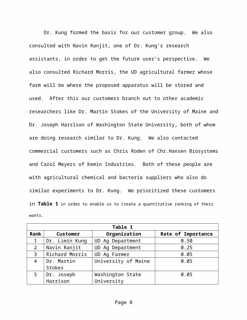
Dr. Kung formed the basis for our customer group. We also consulted with Navin
Ranjit, one of Dr. Kung’s research assistants, in order to get the future user’s perspective. We
also consulted Richard Morris, the UD agricultural farmer whose farm will be where the
proposed apparatus will be stored and used. After this our customers branch out to other
academic researchers like Dr. Martin Stokes of the University of Maine and Dr. Joseph Harrison
of Washington State University, both of whom are doing research similar to Dr. Kung. We also
contacted commercial customers such as Chris Roden of Chr.Hansen Biosystems and Carol
Meyers of Kemin Industries. Both of these people are with agricultural chemical and bacteria
suppliers who also do similar experiments to Dr. Kung. We prioritized these customers in Table
1 in order to enable us to create a quantitative ranking of their wants.
Table 1Rank Customer Organization Rate of Importance
1 Dr. Limin Kung UD Ag Department 0.502 Navin Ranjit UD Ag Department 0.253 Richard Morris UD Ag Farmer 0.054 Dr. Martin Stokes University of Maine 0.055 Dr. Joseph Harrison Washington State University 0.056 Chris Roden Chr.Hansen Biosystems 0.057 Carol Meyers Kemin Industries 0.05
Page 5
These customers expressed various different desires. We took each of these customers
and listed their wants and prioritized them using the weighting shown in Table 2.
Table 2Want Rank Rate of Importance
1 0.252 0.203 0.154 0.155 0.106 0.107 0.05
The top ten of the wants mentioned are listed in Table 3 in a prioritized order. Some wants,
like reproducing desired results, stem from the design’s use as precision laboratory equipment. Other wants are
related to the desires to reduce the physical exertion and tedium of the packing process. Still other wants are
related to the desire to minimize the immediate and future expenditures on the group’s part and also ensure a long
operating life for the equipment. The Rate of Importance column which was used to derive the final ranking of the
wants, is the normalized weighted average of each customers wants.
Table 3Rank Want Rate of Importance
1 Reproduce Desired Results 0.2492 Not Physically Demanding 0.2283 Fast Operation 0.1314 Simple User Operation 0.0915 Low Cost 0.0766 Easy To Clean 0.0677 Easy to Repair/Manufacture 0.0618 Easy to Transport 0.0589 Variable Silo Size 0.02410 Easy to Store 0.015
The customers also expressed certain desires that had to be met by the final design. Our
design must be able to pass through a normal doorway, be movable by two people, be able pack
a silo as fast as current methods, be able to prevent the stopper from being recessed more than a
Page 6

centimeter into the silo, and be built for under five hundred dollars. Most of these constraints
are derived from physical needs of storage and methods that will be used to extract silage from
the test silos themselves.
Concept Generation:
System Benchmarking:
Our team benchmarked a wide variety of systems that perform applications similar to the
job which will be accomplished by the silo packer, these systems are shown in Table 4 in ranked
order of importance.
Table 4Rank System
1 Stokes Pneumatic Loader2 Stokes Front End Loader3 Trash Compactors4 Shot-shell and Cartridge Loaders5 Pharmaceutical Capsule Filling Machines6 Soda Can Crushers7 Current Apparatus
The Stokes Pneumatic Loader is a vertically mounted pneumatic piston driven by an air
compressor. Silage is put into the test silo and an attached filling tube mounted on top of the
silo. The piston then compresses the contents of the silo and the filling tube into the silo at high
pressure. A similar apparatus is also in service with Carol Myers of Kemin Industries.
The Stokes Front End Loader is used to compress the larger test silos. One five-gallon
bucket is filled with silage and another large bucket is put on top of it. A Bobcat then is used; its
hydraulic scoop presses the top bucket into the lower one. The result is a large, compressed silo.
This works well, but the exact pressure exerted onto the silage is hard to measure and sometimes
damage can occur to the silos if the Bobcat operator is not well trained.
Page 7
Trash Compactors have the necessary ability to compact all types of materials. Trash
compactors do not usually put them in any sort of container however and they crush objects to
uniform volume but do not apply a uniform pressure. They do operate quickly and efficiently
however.
Shotshell and Cartridge Loaders have many of the characteristics we are looking for in a
design. The have a feed bin full of material, in this case gun powder, which can be precisely
loaded into a cylindrical container, in this case a bullet casing. The powder is then compressed
in the casing using a piston on a crank. The apparatus is very precise and accurate and is quite
fast as well, but is too small for our needs.
Pharmaceutical Capsule Filling Machines precisely fill objects with a predetermined
amount of material. They do many small capsules at once with multiple pressing fingers and are
very precise because of this approach. The problem here is that these materials are not fibrous
like silage, they are powders or grains which have better packing and filling properties. This
apparatus is also very expensive.
Soda Can Crushers have the right components for a manually powered silo packer if it
were scaled up properly. A lever is used to apply a pressure to an object, in this case it would
have to be the silage not the silo itself. This apparatus is cheap, but cannot exert enough
pressure and would be labor intensive.
After comparing the system benchmarks, we determined that our strongest competitor is
the Stokes Pneumatic Loader. It is less expensive that some of the other systems and its
pneumatic piston provides excellent precision and accuracy while not sacrificing power.
Functional Benchmarking:
Page 8

After we completed our system benchmarking we broke our design into specific tasks
which individual parts of the design would have to accomplish. These tasks are compacting,
material transport, container transport, pressure sensors, and user controllers. This section is
dedicated to an overview of the research we did with these as well.
We examined compacting devices like power presses, pneumatic pistons, extrusion
screws, and pile drivers. After comparing these to each other and our wants, we determined that
the pneumatic piston is the best practice due to its low price and excellent mix of precision and
accuracy in pressure production.
Material transport was looked at with different mechanisms from the lawnmowers and
vacuum cleaners to hydraulic rams and extrusion screws. The best practice in this category is
the screw feeder because it reduces the number of necessary user actions and is highly
compatible with the test silo’s circular geometry.
The silo container itself can be moved through a variety of different methods from the
human hand to a conveyor. The conveyor belt is the best practice here. It is widely used,
inexpensive and is simple to use.
We looked at a multitude of products for measuring pressures ranging from piezoelectric
mats to load cells. The best practice here is the piezoelectric pressure sensor because it is the
most accurate and precise, but unfortunately it is priced much too high for our budget.
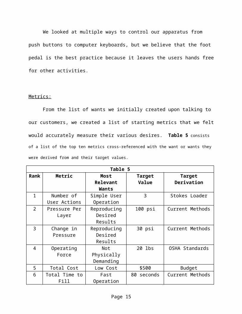
We looked at multiple ways to control our apparatus from push buttons to computer
keyboards, but we believe that the foot pedal is the best practice because it leaves the users hands
free for other activities.
Metrics:
Page 9

From the list of wants we initially created upon talking to our customers, we created a list
of starting metrics that we felt would accurately measure their various desires. Table 5 consists of
a list of the top ten metrics cross-referenced with the want or wants they were derived from and their target values.
Table 5Rank Metric Most Relevant
WantsTarget Value Target Derivation
1 Number of User Actions
Simple User Operation
3 Stokes Loader
2 Pressure Per Layer Reproducing Desired Results
100 psi Current Methods
3 Change in Pressure Reproducing Desired Results
30 psi Current Methods
4 Operating Force Not Physically Demanding
20 lbs OSHA Standards
5 Total Cost Low Cost $500 Budget6 Total Time to Fill Fast Operation 80 seconds Current Methods7 Number of Users Fast and Simple
Operation 2 Stokes Loader
8 Storage Volume Easy to Store and Transport
36 cubic ft. Current Apparatus
9 Number of Silo Sizes
Variable Silo Size 2 Stokes Loader
10 Weight Easily Transportable
88 lbs OSHA Standards
From this list of metrics in Table 5, we determined that the most critical metrics in our
design were the pressure metrics (total and per layer), the time to fill, and the operating force.
These along with the low cost metric, which comes into play due to our low budget, form the
core that we used to roughly rank our concepts. We chose these as the chief metrics for
evaluation because they were simple, but spoke directly to many of the primary concerns of our
customers who want a quick, easy, but accurate and precise method of filling a silo with a low
total cost.
Concept Generation:
Page 10

Concept generation began by looking at the competitors and seeing what processes they
used to create their apparatuses. From there the focus was turned to the best practices in order
beat our competitors by integrating better technology or cheaper systems into our designs.
Concepts are located in several different families with branches that encompass
variations on the same idea. This tree structure logically occurs during any brainstorming
session when one idea leads to another and a good basic concept branches into many variations.
We attempted to use as many of the best practices in the creation of these concepts as possible,
but due to budget limits many of these we not able to integrate many of these systems into the
listed concepts.
Please note that if these written descriptions are not enough to understand the concept,
there are simple schematics of the concepts in the sketches appendix. Also be advised that these
are not the only designs that were conceptualized, but, for the sake of report brevity, we chose
not to include all of the six or seven different concepts that fit in most of the families. We also
wanted to convey the breadth of different design concepts rather that focus on a single area.
1 Extrusion
The Extruders come into play because their extrusion screw allows for continuous
feeding from a storage bin. They incorporate the best material transport benchmark, but
do not include many of the others due to their nature.
1.1 Straight Extruder: This is a classic extruder design. A screw is mounted to a
motor horizontally and draws the silage from a large feed bin and moves it down
into the test silo which is mounted horizontally at the end of the screw. A
constant pressure is kept at the silo end of the screw because the silo is mounted
into a carriage which allows it to move. The screw is always feeding new silage
Page 11

in at the top of the previously compacted silage, until the silo moves so far back
that it trips a kill switch.
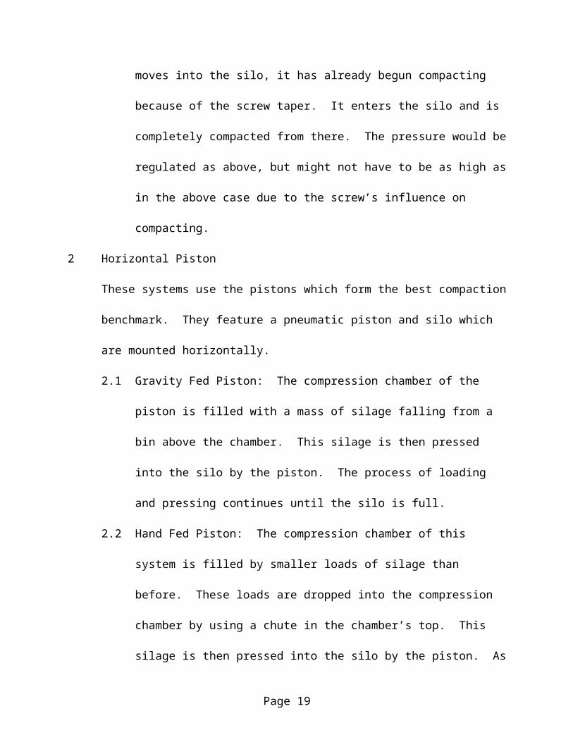
1.2 Tapering Extruder: This is similar to the design above, only instead of a standard
screw, this unit’s screw has a section of changing radius. As the silage moves
into the silo, it has already begun compacting because of the screw taper. It
enters the silo and is completely compacted from there. The pressure would be
regulated as above, but might not have to be as high as in the above case due to
the screw’s influence on compacting.
2 Horizontal Piston
These systems use the pistons which form the best compaction benchmark. They feature
a pneumatic piston and silo which are mounted horizontally.
2.1 Gravity Fed Piston: The compression chamber of the piston is filled with a mass
of silage falling from a bin above the chamber. This silage is then pressed into
the silo by the piston. The process of loading and pressing continues until the silo
is full.
2.2 Hand Fed Piston: The compression chamber of this system is filled by smaller
loads of silage than before. These loads are dropped into the compression
chamber by using a chute in the chamber’s top. This silage is then pressed into
the silo by the piston. As before, the process of loading and pressing continues
until the silo is full.
3 Vertical Piston
These systems use the pistons which form the best compaction benchmark. They feature
a pneumatic piston and silo which are mounted vertically.
Page 12

3.1 Pneumatic Piston with a Vibrating Chute: The complete filling of the silo takes
several iterations of this process and between piston shots the silo is refilled by
sliding silage down into it through a chute which connects to an opening in the
feeding area’s wall. In order to keep the silage moving this ramp is being
vibrated.
3.2 Pneumatic Piston with a Screw Feeder: This design is very similar to the above,
but the feeding chamber and silo are filled with a screw feeder from a large bin
when the piston is not in operation instead of a chute. This is different because it
will allow a much larger feeding bin than the previous concept and utilized one of
our best function benchmarks.
3.3 Crank-Slider with a Hand Loader: This uses an electric motor to power a four-
bar slider mechanism which packs the silage found in the silo and feeding
chamber. The silage is fed into the feeding chamber from a horizontal chute. An
operator is pushing silage through this chute into the feeding chamber with a hand
held pushing tool, similar to what is found in food processors.
4 Other
These are not considered entirely practical, but may be considered innovative solutions to
the problem.
4.1 Centrifuge: Several silos are positioned in arms of centrifuge and spun at high
rates of speed. Silage is fed down a tube in the center of the centrifuge and is
dispersed into each of the arms through the centrifugal force. This design could
load many silos at once, but would have a hard time only filling one because of
possible loading imbalances.
Page 13

4.2 Blower: Silage is blown from a feed bin into the silo at high velocity. This
sudden impact partially compacts the silage and the impact of the silage filling the
silo on top of it finishes the job. This design will most likely have problems due
to the cylindrical cross section of the silo as opposed to the rectangular cross-
section of many blowers.
4.3 Weight Press: Silage is fed into the silo through a chute and is then compacted
through the use of a piston on linear bearings. This piston is rigidly attached to a
step on the side of the apparatus. Operators apply force due to their body weight
to the step when the stand on it, the step is of course hooked to a scale so that the
force exerted by the people on the step can be kept relatively constant.
Concept Selection:
Evaluation:
Our first step in the evaluation process was to do testing on the applicability of several of
our design concepts. Using a clear plastic cylinder of roughly the same dimensions as a test silo,
we started to examine how well silage packed with the different orientations of the silo and
different sizes of the piston. After this we examined the properties of silage in relation to how it
slid and moved through channels.
Diameter Changes and Plungers Design:
The first step we took was qualitatively examine effect lips and sudden changes in
diameter had on the packing process.
Page 14
1) Our initial experiment used a plunger of the same diameter as the silo’s interior and it
showed us immediate problems with such a design. As the plunger moved from the wider
diameter region into the smaller silo, it invariably jammed with silage and was unable to
enter the silo for more the a few millimeters. Even with several people pressing on the
plunger, the silage prevented any and all movement of the plunger past the lip.
2) After this we attempted to compress the silage with a plunger that was noticeably smaller
than the interior diameter of the silo. It passed through the silage around the lip and was
successfully able to enter into the silo. Yet, as our clear test silo showed us, was able to
relatively uniformly compress the silage in the silo itself despite not covering the silos entire
cross-sectional area. This method is not perfect however, we experimented with looser and
denser packing and discovered that the more dense the packing the greater the likelihood of a
jam. We also experimented with the amount of silage that was to be packed and discovered
that the more silage that was used, the higher the chance of jamming.
3) We concluded that lips of any form should be avoided in our final design and the piston
should be smaller in radius than the silo to hopefully avoid jamming.
Orientation:
We examined silo orientation in relation to the uniformity of packing.
1) Our first trials were conducted with a vertical cylinder using small and large packing
volumes. The orientation performed well and uniformly packed the material through
repeated iterations. We noticed that once the silage was packed it tended to stay in the place,
the compacted silage moved very little when fresh silage was compacted on top of it.
Page 15

2) We then switched to a horizontal packing scheme and had our fears about this orientation
confirmed, small silage loads do not pack uniformly. If a silage load is added which does
not completely fill the silo’s cross-section, the packed silage will contain air spaces that run
down the top of the silo. Repeated packing of small silage loads does not alleviate this
problem either as the new silage does not compact the old. This silo orientation also has an
inherent lip in its design where the silage feeds into the compression chamber. If it is
overfilled the piston is more likely to jam, if it is under-filled the packing will be highly non-
uniform.
3) A horizontal silo orientation will not produce reliable results, the silo must be oriented
vertically.
Silage Properties:
We then tested some simple silage properties to see what types of silo loading
mechanisms we could use for the apparatus.
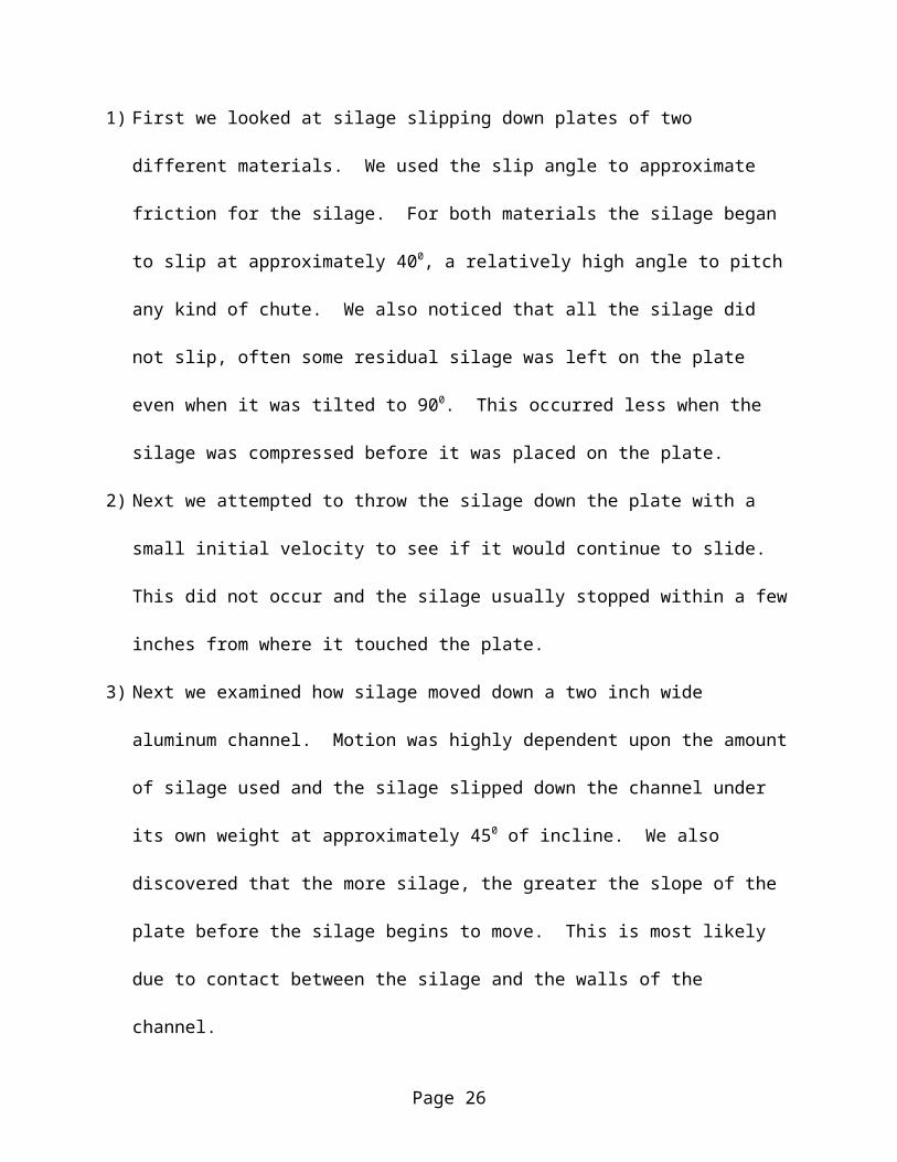
1) First we looked at silage slipping down plates of two different materials. We used the slip
angle to approximate friction for the silage. For both materials the silage began to slip at
approximately 400, a relatively high angle to pitch any kind of chute. We also noticed that
all the silage did not slip, often some residual silage was left on the plate even when it was
tilted to 900. This occurred less when the silage was compressed before it was placed on the
plate.
2) Next we attempted to throw the silage down the plate with a small initial velocity to see if it
would continue to slide. This did not occur and the silage usually stopped within a few
inches from where it touched the plate.
Page 16
3) Next we examined how silage moved down a two inch wide aluminum channel. Motion was
highly dependent upon the amount of silage used and the silage slipped down the channel
under its own weight at approximately 450 of incline. We also discovered that the more
silage, the greater the slope of the plate before the silage begins to move. This is most likely
due to contact between the silage and the walls of the channel.
4) Lastly, we examined what effect a narrowing channel has. We built a channel that narrowed
down to the two inch channel to see if such a feeding ramp would work. Results depended
on the amount of silage, as did the results for the channel, but some things were the same for
all tests. The area where the angled sides changed over to the two inch straight channel was
always trouble spot. The silage could use the angled sides for support even when the channel
was tilted to 900.
5) The conclusion we drew from these experiments is that the silage must be forcibly fed into
the compression chamber, it will not just slide there under its own weight.
Constraints:
Next we eliminated designs which did not fit our customer constraints. Our design must
be able to pass through a normal doorway, be moved by two people, pack a silo as fast as current
methods, prevent the stopper from being recessed more than a centimeter into the silo, and be
built for under five hundred dollars. After pricing the screws necessary to build the extrusion
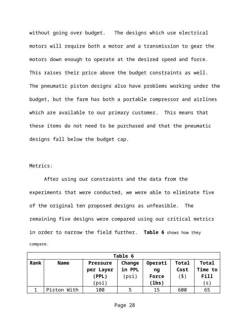
designs, we realized that they were not possible without going over budget. The designs which
use electrical motors will require both a motor and a transmission to gear the motors down
enough to operate at the desired speed and force. This raises their price above the budget
constraints as well. The pneumatic piston designs also have problems working under the budget,
Page 17

but the farm has both a portable compressor and airlines which are available to our primary
customer. This means that these items do not need to be purchased and that the pneumatic
designs fall below the budget cap.
Metrics:
After using our constraints and the data from the experiments that were conducted, we
were able to eliminate five of the original ten proposed designs as unfeasible. The remaining
five designs were compared using our critical metrics in order to narrow the field further. Table
6 shows how they compare.
Table 6Rank Name Pressure per
Layer (PPL)(psi)
Change in PPL
(psi)
Operating Force (lbs)
Total Cost ($)
Total Time to Fill (s)
1 Piston With a Hand Feeder
100 5 15 600 65
2 Piston with Vibrating Chute
100 5 15 500 80
3 Weight Press 100 20 100+ 300 804 Centrifuge 75 30 5 500 1205 Blower 50 30 5 500 40
It is relatively obvious that the weight last three design are not in contention with the first
two due to bad reproducibility or shear repeated physical exertion. After looking at these critical
metrics, we can weed these five possible designs into two leading contenders which we will now
examine further using all of our metrics. Table 7 shows the comparison between the two designs along
with the set target values for each metric and each metric’s relative rate of importance.
Table 7Metric Rate of
ImportanceTarget Value Hand Fed
Crank SliderVibrating Chute
Number of User Actions
0.145 3 3 3
Page 18
Pressure Per Layer 0.124 100 psi 100 psi 100Change in Pressure 0.124 30 psi 5 psi 5 psi
Operating Force 0.112 20 lbs 15 lbs 15 lbsTotal Cost 0.110 $500 $600 $500
Total Time to Fill 0.085 80 sec 65 sec 80 secNumber of Users 0.067 2 2 2Storage Volume 0.061 36 cubic ft. 11.5 cubic ft. 11.5 cubic ft.
Number of Silo Sizes 0.058 2 1 1Weight 0.046 88 lbs 60 lbs 60 lbs.
As is plain to see from our metrics, the hand fed Crank-slider is better than its
competitor, the vibrating feeder in terms of the required time to fill a silo. The hand feeder
actually pushes the silage into the compression chamber, allowing for fast and reliable loading.
The vibrating chute may work well, but it will be prone to clogging if it is overfilled and it lacks
an easy means to clear these blockages. While the hand-feeder is cheaper than any system for
vibrating our loading chute, the motor and transmission for the slider crank is much more
expensive than the pneumatic cylinder.
Final Selection:
The team conducted experiments to determine silage’s material properties and used them
to determine which designs would perform well and which would most likely suffer problems
that would reduce their effectiveness. Then the team made sure than the design could be built
within or very close to our budget. We took the remaining designs that lacked significant
problems and ranked them according to our critical metrics (for brevity). We took the final
Let us now go into more depth with this design. Engineering drawings are located in the
next section of the report if these text descriptions are not clear enough.
Page 19

There are a few basic sections to this design; the piston, the frame, the door, the silo
mount, the silo and extension, the electrical setup, and the pneumatic equipment.
The piston is a 16 in. stroke, 2.5 in. diameter Bimba cylinder with a 1 in driving rod. Its
large stroke length allows for a large compression chamber and its bore size gives a high factor
of safety in compression. The large driving rod allows the piston to accept high shear loading
which may be caused by silage binding around its sides.
The frame is made of two basic pieces: the tube and the plate. The tube is a vertical
piece of 0.25 in. wall, 2in by 2in steel square tubing 40 inches in length. It accepts the high
moment loads of the piston, is easy to connect to, and has a high factor of safety to take into
account any stress concentrations around bolt holes, etc. The plate is 3/8 in steel plate. It is the
surface upon which the silo sits and accepts the high bending load of the piston. These two
pieces are welded together at the base of the tube.
The door is made of 1/16 steel sheet. Its main feature is a large opening which is cut in
the center of its length in order to allow the viewing of the piston’s position. It has 4, ¾ in.
aluminum ribs to give it bending strength along its curved surface. It also has 2 vertical side ribs
to give it strength in the axial direction and allow for easier hinge fixation. The door is attached
to the silo mounts by hinges and is held closer by an automobile trunk mechanism.
The silo mounts themselves are made of aluminum for easy machining. They have
curved surfaces which accept the silo and put it on the pistons axis. There are four mounts
placed along the 16 inch length of the silo and extension. These are bolted to the frame.
The silo and extension are made up of a standard 8 in. long by 2 in. diameter PVC test
silo. The extension is a clear plexiglass tube 8 in. long and 2 in. in internal diameter. These two
are connected using a rubber plumbing coupler. The internal diameters of both objects are the
Page 20

same. This part of the system is removable so that several silos and their extension can be filled
while another is being packed.
The electrical equipment is made up of several components. A limit switch prevents the
apparatus from operating when the door is open. A fuse protects the system from surges and
other phenomenon. A red light tells the operator when the system is live. A rocker switch
completes the circuit and energizes the solenoids in the spool valve allowing the piston to move.
The switch is spring loaded so that the piston always stops if someone is not actively using the
switch. The electrical system runs off a standard household 110 line.
The pneumatic system also has many parts. A regulator is used to monitor and vary the
pressure in the system and the resulting piston force. A safety valve protects the other parts of
the system from damage due to excessive pressure. A needle valve allows the user to alter the
speed at which the piston operates. A spool valve is connected to the electrical system and
governs the direction in which the air flows through the pneumatic cylinder.
Construction
Fabrication
This took place in the machine shop at Spencer Lab and also at the machine shop in 124
Worrilow Hall. A complete section of drawings is found in the appendix.
Because the most of the components of the system were designed to be machined at
relatively low tolerances, we were able to avoid using expensive machine tools like the
Bridgeport Mills in favor of cheaper, less precise tools like a simple drill press.
Most of the parts of the pneumatic and electric systems were bought, not built. Most of
the major electrical components can be bought from Radio Shack’s standard stock. Most of the
pneumatic components can be purchased from Granger and delivered in only a day. This makes
Page 21

the system both easy to build and easy to repair if parts break due to extended use or even
misuse.
Most of the components are bolted or screwed into the final design. If they need to be
removed or replaced for any reason, this can be done quickly and easily. The steel frame itself
was welded into one piece to provide a solid piece on which all the other system components can
be attached.
Most components are made of mild steel in order to be inexpensive and strong enough to
take repeated use. A few parts, like the pistons themselves and the silo mounts, are made of
aluminum. Aluminum was used because of the relative ease of machining it for the silo mounts
and its resistance to corrosion in the case of the piston heads.
Assembly
Assembly took place at 124 Worrilow Hall. Final assembly uses a minimum number of
tools. Final assembly only required a flat head and philips head screwdriver, 7/16 in wrench, ½
in wrench, and a 9/16 in wrench.
System Testing
Testing Plan:
After the prototype was built, its performance had to be compared to the metric target
values. This required a period of testing using a specific testing plan.
1) The prototype was weighted and then a rough estimate of the storage space it will take up
was made using the exterior dimensions of the packer.
Page 22

2) The operating force was estimated after taking the force that was required to operate various
different components. The highest operating force required to operate the packer is the force
required to close the door because of the strength of the door latch.
3) Total cost was calculated from the amount spent to date.
4) The number of silo sizes can be calculated by inspection.
5) The packing time for one person packing a single silo was taken. Different individuals were
used in order to ascertain the level of skill required to operate the packer and whether the
filling time was variant with the user.
6) The packing time for a group of users was taken in order to take into account the effect
multiple packers will have on the system. The old apparatus is designed to be used with
multiple individuals packing the silos in order to speed the packing time. Our apparatus is
packed similarly since the silo and extension can be changed easily between packs.
7) Using the old apparatus we found an average mass of packed silage in a silo. Trials were
then conducted calculating the effect of the change in pressure on the packed density of the
silage. It was found that, while the packer can operate at 100 psi, it packs best at 65 psi. The
amount of silage packed is the same as with previous equipment, but the lower packing
pressure prevents the silage from blowing the lower stopper off the silo as the silage
elastically expands after it is packed.
8) We measured the variation in packing pressure by examining the dynamic fluctuation in
system pressure during the packing of several test silos.
Results:
Page 23

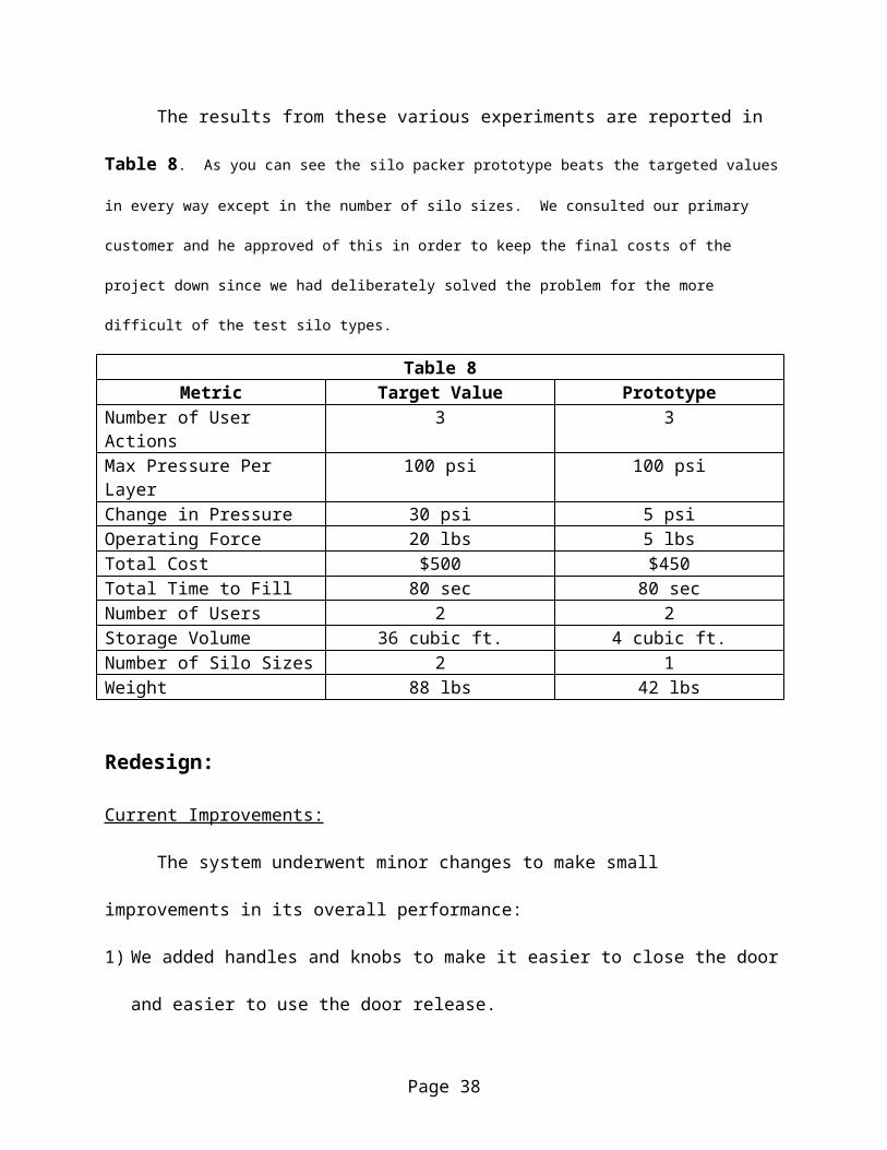
The results from these various experiments are reported in Table 8. As you can see the silo
packer prototype beats the targeted values in every way except in the number of silo sizes. We consulted our
primary customer and he approved of this in order to keep the final costs of the project down since we had
deliberately solved the problem for the more difficult of the test silo types.
Table 8Metric Target Value Prototype
Number of User Actions 3 3Max Pressure Per Layer 100 psi 100 psiChange in Pressure 30 psi 5 psiOperating Force 20 lbs 5 lbsTotal Cost $500 $450Total Time to Fill 80 sec 80 secNumber of Users 2 2Storage Volume 36 cubic ft. 4 cubic ft.Number of Silo Sizes 2 1Weight 88 lbs 42 lbs
Redesign:
Current Improvements:
The system underwent minor changes to make small improvements in its overall
performance:
1) We added handles and knobs to make it easier to close the door and easier to use the door
release.
2) We added steel safety shields around the sides of the silo mounts and between the silo
mounts and the bottom edge of the pneumatic piston. This removes some safety concerns
because fingers cannot be placed in a position where they could be crushed by the piston.
3) We extended the length of the door so that it reaches from the base plate to the bottom of the
silo packer This removes some safety concerns because fingers cannot be placed in a position
where they could be crushed by the piston.
Page 24

4) We gave all the steel parts a coat of primer and a paint job in order to prevent corrosion from
the low pH silage juice and the environment in general.
Suggested Future Improvements:
The following areas could be improved in the future:
1) The door design is rigorous and complex, more rigorous and complex than it really needs to
be. A massed produced packer should remove many of the ribs to save weight.
2) The current design uses a donated spool valve. While this reduces cost, the current valve is
larger and more powerful than is really necessary for our design. A smaller more portable
valve would be preferable if another packer were to be built.
3) The system is rather loud. This sound comes from the exhaust of the pneumatic piston after
its direction is changed. We compensated for this by adding elbows which direct the sound
away from the users, but silencers would be a better solution to this problem because they
would baffle the sound entirely.
Conclusion
TASA was commissioned to design and build a prototype test silo loader for Dr. Limin
Kung of the University of Delaware Agricultural Department. We created a customer list and
benchmarked various systems. We broke our design into different functions like compacting
devices and pressure sensors and did further benchmarking to determine which items were the
best in their particular area. We distilled the customers wants into a list of ten metrics found.
We proposed targets from our benchmarking and determined which metrics were critical to our
design and which were only peripheral to it.
Page 25
We created concepts using our benchmarking as a foundation for ideas, but also reached
beyond it for new and interesting concepts that may give us an edge on the competition. We
performed a series of experiments in order to test basic concepts used in all our designs and to
also determine some basic silage properties. We eliminated some designs and ranked the
concepts that remained. We took our best design, a vertical pneumatic piston, and designed its
various parts.
We fabricated a prototype from these parts designs and then created a testing procedure
for this prototype. Using the results from the testing procedure in order to chart its performance
within our metrics. We evaluated the prototype’s performance against the target values set by
the metrics and made minor redesigns to specific areas. We also showed the original prototype
to Dr. Kung, who had some of his own comments.
We then slightly redesigned and rebuilt the prototype into order to increase the design’s
performance in several metrics and in order to create a safer final product. The end result was
the final prototype which was presented on Friday, April 23.
Our customer is more than satisfied with our work and is looking forward to being able
to use the completed apparatus when his testing begins again in the summer.
Page 26

Appendix I:
Engineering Drawings:
Page 27

Page 29

Page 30

Page 31
Page 32

Page 33

Page 34

Page 35

Page 36

Page 37
Page 38
Page 39
Appendix II:
Budget:
PART QTY PRICE $Pneumatic Piston 1 215.00Regulator 1 28.00Needle Valve 1 37.00Safety Valve 1 15.00Plexiglass Tubing, 6 ft. 1 60.00Rubber Couplers 9 45.003/8 in. Steel Plate 1 4.501/16 in Steel Sheet 1 3.00Hinges 2 5.00Safety Rubber 1 6.00Aluminum Silo Mounts 4 5.00Steel Square Tubing 1 30.00
TOTAL 453.50
Appendix III:
Sketches:
Straight extruder
Tapered extruder
Gravity Fed Piston
Hand Fed Piston
Page 41

Pneumatic Piston with a Vibrating Chute
Page 42

Pneumatic Piston with a Vibrating Chute
Crank Slider
Page 43

Centrifuge
Blower
Page 44

Weight Press
Page 45