Embed Size (px)
Citation preview

Stock No. Machine No LS-0285
IMPORTANCEOperate, check and maintain this machineafter reading this instruction manual andthe manual concerned with attached deviceand then understanding the contents.
NC LASERCUTTING MACHINEPROGRAMMING MANUAL


CONTENTS
PL SAFETY WARNING PageIntroduction PL-010A 1Safety instrucitons PL-020A 2
PA GENERAL 3Genaral PA-001A 4Usable codes in program PA-010A 6Input form PA-020A 8Floppy disk drive (FDD) PA-040A 11Precautions for this manual PA-090A 12
PB PREPERATORY FUNCTIONS 13Preparatory funciton list PB-200A 14Positioning (G00), Linear Interpolation (G01) PB-210A 16Circular arc interpolation (G02,G03) PB-220B 17Interpolation when the end point is not locatedon the circumference PB-230A 19
Programming the circular arc (1) PB-240A 20Programming the circular arc (2) PB-241A 22Beam diameter conpensation (G41, G42) PB-250A 25Beam diameter compensation (G40) PB-251A 27Caution for beam diameter compensation PB-252A 28Prevention of overcutting by tool diameter compensation PB-254A 30Exact stop (G09, G61, G64) PB-270B 31Dwell (G04) PB-280A 33Coordinate system setting (G92) PB-290A 34Absolute and incremental commands (G90, G91) PB-292A 35Inch/Metric conversion (G20, G21) PB-293A 36
PC AUXILIARY FUNCTIONS 37Auxiliary codes PC-002B 38Auxiliary functions PC-010C 40

CONTENTS
PD OTHER FUNCTIONS 45Speed command PD-010A 46Optional skip funciton PD-020A 47Incremental / Absolute command PD-050A 48Beam diameter compensation PD-060A 50Corner process PD-070B 52Radial error for circular arc PD-080A 54Speed control for small circular arc PD-090A 55Laser power command (SPF_LASER_ON, OFF) PD-110E 56Process condition setting function (SPF_COND) PD-115E 58Command at lead-out PD-181A 63Method of cutting thick plate PD-184A 64
PE CONFIGRATION OF PROGRAM 67Program configuration PE-002A 68Main program and sub program PE-040A 71
PF EXAMPLE OF PROGRAM 77Example of program (Laser marking) PF-160A 78Example of program (Punch marking) PF-161A 80Example of program (Marking) PF-162A 82
Cutting sample program (SS400) Round corner PF-170A 83Cutting sample program (SS400) Minute corner PF-171A 86Cutting sample program for removal of coating PF-172A 89Cutting sample program(SUS304 O2 piercing, N2 cutting, No small circle) PF-173A 92
Cutting sample program(SUS304 O2 piercing, N2 cutting, Small circle is provided.) PF-174B 95
Cutting sample program(SUS304 N2 piercing, N2 cutting, No small circle) PF-175B 98
Cutting sample program(SUS304 N2 piercing, N2 cutting, Small circle is provided.) PF-176B 101

PROGRAMMING SPECIFICATIONS
COORDINATE SYSTEMAXIS CHANGE ×LONGITUDINAL AXIS Y-AXIS
HAND CHANGE (LEFTHANDED) ×
LASER CUTTING SPECIFICATION (TRUMPF TLF6000t)MILD STEEL (HSQ PIERCING) ○
MILD STEEL (IMMEDIATE SPEED PIERCING(QUICK PIERCING)) ○
MILD STEEL (V-CUT) ×STAINLESS STEEL (OXYGEN CUTTING) ○
STAINLESS STEEL (NITROGEN CUTTING) ○
STAINLESS STEEL (AIR CUTTING) ×ALUMINUM STEEL (NITROGEN CUTTING) ×
OTHERSLASER MARKING (OXYGEN) ○
LASER MARKING (NITROGEN) ○
POWDER MARKING (LINE TYPE) ×POWDER MARKING (CHARACTER TYPE) ×DOT PRINTING DEVICE FOR PEN MARKING ×


PL-010A 1/1 Preface
This book is a manual for describing the method of operating this machine, and for operating safely and correctly.
Be sure to read this manual before using this machine. And then use this machine after understanding this operation method enough.
In the case of using it without following the detail of this manual, the serious accident, malfunction and the size error of product, etc might be occurred. Therefore pay attention to them.
Warning This machine is manufactured considering safety enough. However, when using
this machine incorrectly, serious accident, malfunction and the size error of product, etc might be occurred.
As for the operator and the person in charge of handling of this machine, read this book well before operating or maintaining this machine.
All persons who handle this machine should regularly read this book with keeping as a handbook. 1. Do not use this machine until understanding the description of this machine
completely. 2. Keep this book at hand always. Moreover, read especially repeatedly for
“Warning”, “Caution”, and “Importance”, and confirm the content. 3. When losing or damaging this book, order to KSK or the sales service shop of
KSK soon. 4. When this machine is transferred, transfer it to the next owner with
appending this book without fail. 5. Interpret the objects which are not written as meaning “possible” in this
manual especially as “impossible”.
1

PL-020A 1/1 Guide of safety
Many accidents are occurred due to operation, check, and maintenance, which are not observed a basic safety rule. Read all the prevention methods and notes in this book well without fail before handling this machine. Never handle this machine before the detail of this manual is surely acquired. To have safety understood correctly, the expressions to safety are united, and the safety symbols are also indicated with deciding them in this book. Those contents are as below.
Warning It is used for message and indication label as for the part where might cause the serious injury or serious accident by malfunction and the size error of product unless it is avoided. Caution It is used for message and indication label as for the part where might cause the slight injury or damaged machine and the size error of product unless it is avoided. Moreover, it is also used in the case of paying attention to a dangerous performance. Importance It is used for a basic observation matter of legal control etc which should observe naturally.
2

PA-000 1/1
PA GENERAL
3

PA-001A 1/2 General
General The controlled axis motion by numerical control device (hereinafter referred to as NC device) of this machine is as below.
(1) Transverse feed of carriage mounting the torch block (2) Forward/backward motion for rail directions (3) Torch lifting feed (Z-axis) (4) Torch focal spot movement (V-axis) The relation between each axis and torch block is shown as below figure. [Axes names are not changed.]
+Y
-X +X
-Y
Y Y11
(Righthanded)
Y11 YX
V Z
(Lefthanded)
X
V Z
[Axes names are changed.]
+X
+Y -Y
-X
X X11
(Righthanded)
X11 XY
V Z
(Lefthanded)
Y
V Z
4

PA-001A 2/2 General
The input information for NC device of this machine contains variable block with decimal point, word address and format (ISO840) and is provided from the floppy disk, memory card (option) or automatic programming device through the LAN (option).
Warning
When a floppy disk is covered with magnetism, heat, water and dust, it may damage internal data and cause the machine to malfunction. To avoid such things, store the floppy disks in a special storage box capable of protecting them from magnetism, heat, water, dust, etc.
Moreover, a program divides a figure into circular arcs and line segments with approximating to them. These circular arcs and line segments constitute a coordinate system which origin is zero point and the type of switching incremental or absolute which specifies the coordinate of the end point and center of the circular arc. And then they consist of the block for each movement command.
Besides this movement command block, 1 block consists of only each various function required for this machine.
Moreover, the contents of input information are registered in NC internal memory and that contents of program can be edited also.
Warning
The manual describes general matters. Consequently, practical operation may be restricted according to this machine specifications etc in actual operation. Therefore, read each manual provided with this machine carefully before handling this machine.
5

PA-010A 1/2 Usable codes in program
Usable codes in program ISO code
0 – 9 : Digits ・ : Decimal point F : Feeding rate per minutes (mm/min) G : Preparatory function I : X-axis component of the center of circular arc in Cartesian coordinates J : Y-axis component of the center of circular arc in Cartesian coordinates M : Auxiliary function X : Specification of X-axis and dwell time Y : Y-axis Z : Z-axis V : V-axis N : Block number address CR= : Circular arc radius D : Specification of offset (kerf compensation) number P : Program repeat O : Not allocated (Ignored) + : Between the address code and digit Positive (ignored) - : Between the address code and digit Negative Tab : Tabulator (ignored) L
F : Block end character (LF) Space : Space (ignored) / : Optional skip ; : Annotation
Caution 1 block length contains maximum 512 characters (including the comment and block end characters).
Code characters should be used only in English. Be careful not to misunderstand the below content. 1. When the methods except for above input method are specified,
the machine might malfunction. Therefore, pay enough attention to the specification failure, etc.
6

PA-010A 2/2 Usable codes in program
Program name Program name is different depending on each program. Program name must be taken
into account the below conditions. 1. 2 characters at the beginning must be alphabetic characters (or underlined
alphabetic characters). 2. Others must be alphabetic or numeric characters. 3. Maximum 24 characters 4. Symbol – cannot be used. 5. Extension must be MPF. Example:
_MPF100.MPF SHAFT.MPF AB0001.MPF Block length
1 block length contains maximum 512 characters (including the comment and block end characters).
Word order in block
To define the block structure as much as possible, the word in block should be arranged as below.
N10G…X…Y…Z…F…D…M… N Block number address 10 Block number G Preparatory function X,Y,Z Position data F Speed D Tool offset number M Auxiliary function
7

PA-020A 1/3 Input form
Input form is the ISO (variable word address block) format based on the word/address system. The designation forms are as below. 1. G3, X±63, Y±63, Z±63, V±23, I±63, J±63, F63, N4, M3, D2, Lf, CR±63
Meanings of above each designation are as below. a) G3: Preparatory function
Specify the preparatory function with a numeric value up to 3 digits. Refer to the later chapter for preparatory function.
b) X±63: X-axis movement distance (mm) Specify the X-axis coordinate value of end point with the signed numeric value in coordinate system that a start point is zero point. 6 is the maximum digit number more than decimal point and 3 is the maximum digit number less than decimal point. The decimal point is not required for the program. Maximum value 999,999.999
c) Y±63: Y-axis movement distance (mm) Specify the Y-axis coordinate value of end point with the signed numeric value in coordinate system that a start point is zero point. Others are the same as X±63. Maximum value 999,999.999
d) Z±63: Z-axis movement distance (mm) Specify the Z-axis coordinate value of end point with the signed numeric value in coordinate system that a start point is zero point. Others are the same as X±63. Maximum value 999,999.999
e) V±23: V-axis movement distance (mm) Specify the V-axis coordinate value of end point with the signed numeric value in coordinate system that a start point is zero point. 2 is the maximum digit number more than decimal point and 3 is the maximum digit number less than decimal point. The decimal point is not required for the program. Range of command value 0.000mm ~ 15.000mm
8

PA-020A 2/3 Input form
f) I±63: X-axis coordinate value in center of circular arc (mm) Specify the Z-axis coordinate value of the center of circular arc with the signed numeric value in coordinate system that a start point is zero point. Others are the same as X±63. Maximum value 999,999.999
g) J±63: Y-axis coordinate value in center of circular arc (mm) Specify the Y-axis coordinate value of the center of circular arc with the signed numeric value in coordinate system that a start point is zero point. Others are the same as X±63. Maximum value 999,999.999
h) F53: Speed command (mm/min) Specify the feed speed with actual speed. Command value range 0.001 ~ 99999.999
i) N4: Sequence number
j) M3: Auxiliary function
Specify the auxiliary function with numeric value up to 3 digits. Refer to the later chapter for auxiliary function.
k) D: Offset number Use it to input the specified value of offset (kerf compensation) value in each memory from D01 to D32 beforehand.
l) Lf: End of block Be sure to specify it as a segment of block.
m) CR±53: Circular arc radius (mm) Command a circular arc radius to be specified. Command it with a signed numeric value depending on whether the arc length of a circular arc is by more or less than 180 degrees of central angle. 180 degrees or more: Positive + 180 degrees or less: Negative - Maximum specified value less than 360 degrees
9

PA-020A 3/3 Input form
Caution Be careful not to misunderstand the below contents.
1. Refer to the detailed description of later chapter for each command because this input form describes the general ISO format.
2. The symbol of plus (+) can be omitted for the symbols from b) to g). Also the characters X, Y, Z, V, I, J of each can be omitted in the case that the numeric value is 0 in incremental command program.
3. The numeric value 0 of a) cannot be omitted, but the 0 before other numeric value can be omitted. Example X50 X50.0 X50.5 X50.5 F3000 F3000.0
10

PA-040A 1/1 Floppy disk drive (FDD)
As for the method of data input for NC device, it is possible to use the 3.5-inch floppy disks as below format (IBM: PC/AT compatible machines)
1. Format
2HD Contents at unformat (MB) 2Contents at format (KB) 1440Cylinder 80Bytes / Sectors 512Sectors / Track 18Total number of track 160Number of registration files 224
2. Use the ASCII code. Therefore, EOB (End of Block) codes are C
R LF(0Dh 0Ah)
or LF(0Ah).
3. File methods are as below.
;Program Comment as required G21 G92X0Y0 G91 SPF_COND(1,101,16,0); Loading the cutting chart data G00X…Y… SPF_PROG_END(); End procedure M30; End of program
4. The file name shall be input in alphanumeric character by 24-digits and the extension shall be input only MPF. Furthermore, extension cannot be omitted. (The symbol – cannot be used.) [Example]: WK0001.MPF BMW777KOIKE0001.MPF
5. It cannot respond to directory structure of MS-DOS. Therefore it is necessary to create the file in root directory.
11

PA-090A 1/1 Precautions for this manual
Caution
This manual contains various examples for some programs in each part. The following standards are applicable to all examples described in this manual. 1) Coordinate axis
The mathematical coordinate axes shall be applied usually when the X and Y axes are not indicated in figure. In other words, the +X axis shall be assumed at the right side of the paper sheet, while the +Y axis shall be assumed at the up side.
2) Start point and end point of the block The start point of the block shall be indicated by means of the symbol SP (Start Point), the end point by means of EP (End Point) and the direction of progression by means of the arrow.
3) Direction of kerf compensation. The direction of kerf compensation is indicated by means of the arrow mark (↑) on the profile of the program instruction.
12
PB-000 1/1
PB
PREPARATORY
FUNCTION
13

PB-200A 1/2 Preparatory function list
The preparatory functions provided in this machine are as below.
Codes Group Function G00 ☆ 01 Positioning (rapid) G01 01 Linear interpolation (process feed) G02 01 Circular arc interpolation (clockwise) G01 01 Circular arc interpolation
(counterclockwise) G04 18 Dwell G09 18 Exact stop G20 06 Inch input G21 ☆ 06 Millimeter input G40 ☆ 07 Beam diameter compensation cancel G41 07 Beam diameter compensation in left side G42 07 Beam diameter compensation in right side G61 10 Exact stop start G64 10 Exact stop end G90 ☆ 03 Absolute command G91 03 Incremental command G92 18 Coordinate system setting
Note) Refer to the “English manuals for Yaskawa Siemens CNC series, Programming
Manual for Machining Center” for other G codes.
14

PB-200A 2/2 Preparatory function list
The command of preparatory function is expressed according to the numeric value following the address G (G code) and regulates the means of command including the block. There are 2 versions of G codes as below.
Type Explanation One-shot G mode Valid G code only for specified block Modal G mode Valid G code until other G code in the same group is
commanded [Example] G01, G00 are modal G codes in the same group. G01X Z G01 is valid during this interval. X G00X
Caution Be careful not to misunderstand the below contents.
1. The G codes including ☆ mark show that getting each state of those G codes at power on or at reset.
2. G codes of 18 groups show the G codes not modal and only specified programs are enabled.
3. Commanding the G codes not described in this manual or “English manuals for Yaskawa Siemens CNC series, Programming Manual for Machining Center” might cause the alarms to be displayed.
4. Several G codes can be commanded in the same block if those G codes are in the different group. In the case that 2 or more G codes belong to the same group are commanded in the same block, the G code specified after is enabled.
5. G codes are displayed per each group number. 6. Be sure to command the G code in the beginning of the block.
15

PB-210A 1/1 Positioning (G00), Linear interpolation (G01)
Positioning (G00) This code is commanded for positioning without performing cutting, marking, etc. Feed rate in this command is automatically set at the rapid feed rate. In a block that contains this code, the feed route up to the end point is not determined in general. (Moreover, it is considered that this function is commanded when the later G40 (Kerf compensation) is in cancel mode.) [Example 1]
140
490
SP
EP
G00 X490. Y-140.
Linear interpolation (G01) This function is commanded for feeding on a straight line. Feed rate follows F command. In case of marking, marking speed is set. [Example 2]
210
525
SP
EP
G01 X525. Y210.
16

PB-220B 1/2 Circular interpolation (G02, G03)
Circular interpolation (G02, G03) This functions is used in the case of feeding on circular arc section. The feed speed is same as the one of linear interpolation. G02 and G03 are performed as shown in the examples. [Example 1]
200 250
SP EP G03 X250. Y-250. I250. G02 X200. Y-200. I200.
200 250
250R
200R
[Example 2]
20 40
SP
EP
G03 X20. Y-40. I-30. J-40. or G03 X20. Y-40. CR = -50.
30
50R
[Example 3]
40
G02 I-30. J-40.
30 50R
When the round circle is specified, the CR cannot be used. When the CR is used, an arc of 0°is programmed and the machine doesn’t move.
17

PB-220B 2/2 Circular interpolation (G02, G03)
[Example 4]
0 90 120 140 200 X
40
60
100 Y
60R 50R
The above tool track can be programmed as follows;
1. In absolute programming G92 X200.0 Y40.0 Z0 ; G90 G03 X140.0 Y100.0 I-60.0 F300. ; G02 X120.0 Y60.0 I-50.0 ;
2. In incremental programming G91 G03 X-60.0 Y60.0 I-60.0 F300. ; G02 X-20.0 Y-40.0 I-50.0 ;
The feed speed in circular interpolation is equal to the feed speed specified by the F code, and the feed speed along the arc (the tangential feed speed of arc) is controlled to be the specified feed speed.
Caution
Be careful not to misunderstand the below contents. 1. I0 and J0 can be omitted. 2. When both X and Y are omitted (or the end point is same as the start point
position) and when the center is specified with I and J, a 360°arc (round circle) is specified.
G02 I (Command for a round circle) 3. The alarm is occurred when an arc with radius 0 is commanded.
18

PB-230A 1/1 Interpolation when the end point is not located on the circumference
Interpolation when the end point is not located on the circumference In the case that the specified end point is not located on the specified circular arc, what the circular arc is changed from start point to the end point gradually causes the spiral to be created so that the end point is placed on the specified circular arc.
Radius compensation value by unit angle
Circular arc compensation
End point inside of circumference End point outside of circumference
19

PB-240A 1/2 Programming the circular arc (1)
Programming a circular arc In the case of programming a circular arc, the coordinate values of start point, end point and center of circular arc must be specified. The center coordinate values of circular arc are obtained by commanding the coordinate value seen from the start point. In that case, X-coordinate value in the center coordinate of circular arc seen from the start point is obtained as I, while the Y-coordinate value is obtained as J. There are two types of circular arcs such as the clockwise circular arc and the counterclockwise circular arc. Accordingly, G02 is used in the case of commanding the clockwise circular arc, while G03 is used in the case of commanding the counterclockwise circular arc.
+X
+Y EP
100 SP
100 Center of circular arc
G02 X100. Y100. I100. J0
+X
+YEP100
SP 100
Center of circular arc
G03 X100. Y100. I100. J0
+X
+Y EP
20
SP
50
Center of circular arc
G02 X70. Y36.9 I50. J-10.
+X
+Y EP
20
SP
50
A= 502+102 = 50.99 B= 50.992-202 = 46.90 C= 46.90-10 = 36.90
10 10 A
C B
20

PB-240A 2/2 Programming the circular arc (1)
5010
EP
50
SP 2520
+X
33.2 16.6
+Y
G02 X70 Y36.9 I-50. J-10. G03 X50. Y33.2 I25. J16.6
In the case of commanding a round circle
300 400
500
+X
+Y
G02 X0 Y0 I-300. J-400. or
G02 I-300 J-400.
21

PB-241A 1/3 Programming the circular arc (2)
For CR command In the case of commanding the circular arc, there is a method to specify the start point and end point of arc or the arc radius instead of specifying the center of arc with I and J.
100
100
G02 X100. Y100. CR=100.
100 100
G03 X100. Y100. CR=-100.
EP
SP
EP
SP +X
+Y
+X
+Y
When the angle of commanding circular arc is less than 180°seen from its center in the case of commanding the circular arc, the CR is left as it is. However, when the angle exceeds 180°, it is necessary to attach the (-) symbol to CR because the cases shown as below figures are obtained.
22

PB-241A 2/3 Programming the circular arc (2)
SP
50
EP
20
50
(1)
(2)
60
For example: G02 X60. Y20. There are two possibilities as (1) and (2) in the case of considering a circular arc with radius 50. The two cases are discriminated as below.
(1) G02 X60. Y20. CR = -50. (2) G02 X60. Y20. CR = 50.
+X
+Y
EP
20
SP
50
G02 X70. Y36.9 CR = 50.99 ; B = (36.9+10)2+202
10
60 SP
50 EP
20
50
(1)
(2)
180 º or more
180 º or less
36.9
23

PB-241A 3/3 Programming the circular arc (2)
50 10
EP
50
SP 25 20
+X
33.2 16.6
+Y
G02 X70. Y36.9 CR = 50.99 ; G03 X50. Y33.2 CR = 30. ; 30 = 252 + 16.62
24

PB-250A 1/2 Beam diameter compensation (G41, G42)
Beam diameter compensation (G41, G42) When a cutting profile is specified without taking into account a kerf width at cutting,
the edge of material is located on the inside by half the kerf width. Therefore, a material of the required dimensions cannot be obtained. The function of beam diameter compensation compensates for the dimensional error. “Beam diameter compensation Left” specifies the beam compensation on the left side as viewed from the cutting profile progressing direction, while “beam diameter compensation Right” specifies it on the right side.
Once this function is commanded, the value of beam diameter compensation is assured for the subsequent profile. However, at the corner part, the compensation direction is changed by a straight line instead of compensation rotation on the arc whose radius corresponds to the value of beam diameter compensation with the corner located at the center.
Moreover, the motion of beam diameter compensation at commanding this function moves to the normal direction for the profile by the set value according to MDI (Manual Data Input) at the block end when the next profile command is executed. (Command of only beam diameter compensation ON is inadequate for compensation. Therefore, offset number D must be commanded at the same time.) Above each motion is shown as below. 〔Example 7.〕
180
EP
180R
350
SP
280
G41 D01 G01 X350. Y280. G02 X180. Y-180. J-180. Kerf compensation value is offset by the value input in the memory of D01.
25

PB-250A 2/2 Beam diameter compensation (G41, G42)
D code Compensation (mm) D code Compensation (mm)
D01 0.05 D11 0.55 D02 0.10 D12 0.60 D03 0.15 D13 0.65 D04 0.20 D14 0.70 D05 0.25 D15 0.75 D06 0.30 D16 0.80 D07 0.35 D17 0.85 D08 0.40 D18 0.90 D09 0.45 D19 0.95 D10 0.50 D20 1.00
D21 The value is variable according to laser setting.
26

PB-251A 1/1 Beam diameter compensation (G40)
Beam diameter compensation OFF (G40) This function is commanded for canceling the value of beam diameter compensation set by
“Beam diameter compensation Left or Right” after cutting. Actual movement according to this function is reverse to that caused by “Beam diameter
compensation Left or Right.” [Example 9.] 100
100
100
G01 X100. Y100. G40 G01 X100.
[Example 10.]
100
100
100
G01 X100. Y100. ;G40 G01 X100. ;
27

PB-252A 1/2 Caution for beam diameter compensation function
Caution Be careful not to misunderstand the below contents. (1) Even when the diameter compensation function G41 or G42 is programmed, beam
diameter compensation is not applied to the profile actually before any of D01 to D20 is programmed.
(2) In the case that the beam diameter compensation is applied, the value of beam diameter compensation must be input in memories from D01 to D20 beforehand. D21 changes according to the laser setting chart at executed.
(3) When executing the beam diameter compensation ON/OFF (G40, G41, or G42), it must not be executed in circular arc command. Otherwise an alarm will be occurred.
(4) Do not command more than 3 blocks without moving continuously during executing the beam diameter compensation because the beam compensation value on the block joint might be changed.
For 1 or 2 blocks without moving For 3 blocks without moving
(5) The method that the beam diameter compensation is applied in the case that the
direction of beam diameter compensation is changed during the program is as below. However, when each A, B and C block is not located on the straight line, an alarm is occurred.
G41G42 G42
A B C
28

PB-252A 2/2 Caution for beam diameter compensation function
Caution (6) When offset value is changed at the mid-point of program:
Calculated from the beam diameter compensation value specified in block N7
Calculated from the beam diameter compensation value specified in block 6
N6
N7
N8
(7) Even when the internal angle R smaller than the value of beam diameter compensation is commanded, an alarm is not occurred.
29

PB-254A 1/1 Prevention of overcutting by tool diameter compensation
Case that the contour track is shorter than the tool diameter The tool moves to the corner of material on the transition circle with following the
programmed contour correctly.
Tool track
Programmed contour
Case that the tool diameter is too widen for machining inside
Process the contour only so that the contour is not damaged.
Tool track
Programmed contour
30

PB-270B 1/2 Exact stop (G09, G61, G64)
1. Exact stop (Automatic acceleration/deceleration) (G09) This function is commanded for the linear and circular interpolation commands when
decelerating at the end point and accelerating at the start point. EP
SP 150
350 Acceleration
Deceleration
G09 G01 X350. G01 Y150.
MD20150 [11] = 2 (rough) or 3 (minute) MD36000 Positioning completion width setting (rough) Usual setting 0.04mm MD36010 Positioning completion width setting (minute) Usual setting 0.00mm Usual MD20150 [11] = 3 After the command delivery is completed, start moving to the next block.
2. Exact stop mode (G61)
According to G61 command, as for the movement command until G64 is commanded since G61 command, after decelerating the feed speed to “0” at the end of each block and then confirming that the machine gets in-position state (positioning completion), move to the next block. However, the below setting is required.
MD20150 [11] = 2 (rough) or 3 (minute) MD36000 Positioning completion width setting (rough) Usual setting 0.04mm MD36010 Positioning completion width setting (minute) Usual setting 0.00mm Usual MD20150 [11] = 3 After the command delivery is completed, start moving to the next block.
31
PB-270B 2/2 Exact stop (G09, G61, G64)
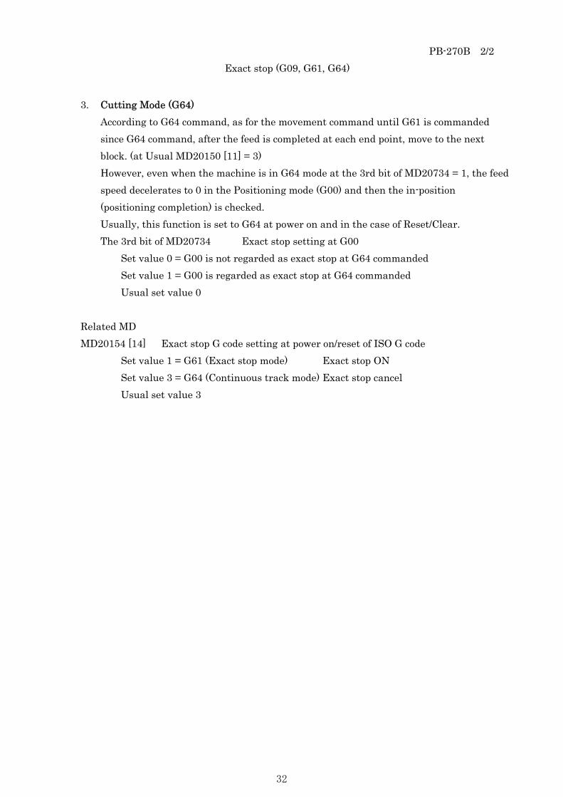
3. Cutting Mode (G64) According to G64 command, as for the movement command until G61 is commanded since G64 command, after the feed is completed at each end point, move to the next block. (at Usual MD20150 [11] = 3) However, even when the machine is in G64 mode at the 3rd bit of MD20734 = 1, the feed speed decelerates to 0 in the Positioning mode (G00) and then the in-position (positioning completion) is checked. Usually, this function is set to G64 at power on and in the case of Reset/Clear. The 3rd bit of MD20734 Exact stop setting at G00
Set value 0 = G00 is not regarded as exact stop at G64 commanded Set value 1 = G00 is regarded as exact stop at G64 commanded Usual set value 0
Related MD MD20154 [14] Exact stop G code setting at power on/reset of ISO G code
Set value 1 = G61 (Exact stop mode) Exact stop ON Set value 3 = G64 (Continuous track mode) Exact stop cancel Usual set value 3
32

PB-280A 1/1 Dwell (G04)
Dwell (G04) This function is used to specify the dwelling time of the machine by means of the alphabetic character X followed by a numeric value. The dwelling time is commanded in units of milliseconds, and its maximum value is 99,999.999.
Example: G04 X60
or G04 X60.0
The dwelling time is 60 seconds in this case. It is not possible to cancel the rest of the time during the execution of this function.
33

PB-290A 1/1 Coordinate system setting (G92)
Coordinate system setting (G92) The coordinate of workpiece system is changed by the below command. G92 ; This command causes the workpiece system to move so that a tool point such as the tip
corresponds to the workpiece coordinate system selected at that time. Absolute command commanded hereafter is commanded at the position in the workpiece
coordinate system.
+X
+Y
25.2
23.0
The workpiece coordinate system moves so that the tip of tool corresponds to the coordinate
value commanded by G92 such as above figure of new workpiece coordinate system after G92 command (G92X25.2Y23.0) and then the new workpiece coordinate system is created. The position indicator is reset to 0 by the below program. G92 X0 Y0 MDI and CRT position display and external position display are reset as well. The coordinate value of ABSOLUTE is 0 on the position display of CRT. When the program restart function is used, G92X0Y0 must be set at the beginning of
program in coordinate.
34

PB-292A 1/1 Absolute and incremental commands (G90, G91)
There are two methods of commanding the movement value for each axis such as absolute command and incremental command. An absolute command is a method of programming the coordinate value of the end point of movement value for each axis. An incremental command is a method of directly programming the movement value of each axis itself. G90 and G91 are commanded to execute the absolute command and incremental command respectively. In the case of above figure, programming by incremental command causes the below command: G91 X-60.0 Y40.0 On the other hand, programming by absolute command causes the below command: G90 X40.0 Y70.0
70.0
30.0
40.0 100.0
Start point
End point
Y
X
35

PB-293A 1/1 Inch/Metric conversion (G20, G21)
Either inch or metric input can be selected by G codes.
Least input unit Unit system
G code Set unit
inch G20 0.001 inch mm G21 0.001 mm
This G code must be commanded in an independent block before setting the coordinate system at the beginning of the program. The unit systems of the following items are changed after inch/metric conversion by G code.
a) Feed speed command by F code b) Positional command c) Offset value of workpiece zero point d) Unit of 1 scale for manual pulse generator e) Movement value in incremental feed
Caution Be careful not to misunderstand the below contents. 1. The unit of input for the machine is used only for metric system. 2. G20 cannot be commanded.
36

PC-000 1/1
PC
AUXILIARY
FUNCTION
37

PC-002B 1/2 Auxiliary codes
The auxiliary functions available to this machine are as below.
M code Function ※ M00 Program stop ※ M02 Program end M14 Buzzer ON ※ M17 Sub program end M24 Touch alarm disabled M28 Torch hold ON M29 Torch hold OFF ※ M30 Program end ※ M90 Auto power-off M107 Touch alarm enabled SPF code SPF_COND(n,n,n,n) Loading the cutting chart data of process condition SPF_LASER_ON(n,n) Cutting start command (including the piercing motion) SPF_LASER_OFF(0) Cutting end command SPF_E_CODE(n) Cutting chart change command SPF_SPEED(n) Speed change command SPF_T_HOLD(n) Torch hold command SPF_PROG_END(0) Automatic operation end SPF_LSAKI_ON(0) Removal of coating start SPF_LSAKI_OFF(0) Removal of coating end SPF_LMARK_ON(0) Laser marking start SPF_LMARK_OFF(0) Laser marking end SPF_LPUNCH(0) Punch marking start
※ SPF_MPOWDER_ONOFF(1) Spray marking ON (Option) ※ SPF_MPOWDER_ONOFF(0) Spray marking OFF (Option) ※ SPF_PMARK_ONOFF(1) Spray marking preheat ON (Option) ※ SPF_PMARK_ONOFF(0) Spray marking preheat OFF (Option)
38

PC-002B 2/2 Auxiliary codes
Caution Be careful not to misunderstand the below contents. 1. Command the auxiliary codes with ※ mark in single block. 2. Do not command the auxiliary codes except for the ones described in this list.
39

PC-010C 1/4
Auxiliary functions
Descriptions of auxiliary functions Descriptions of auxiliary functions are as below. Refer to the PC-002 for the M code available to this machine. 1. Program stop (M00)
The function stops the torch block at optional point on the material before or after cutting start, and leaves the decision of a restart to the operator.
(Press the
START switch on operation panel to restart the program.) Therefore, command it in the following cases. a) When some manual operation is needed before or after cutting (or marking). b) When various confirmation operations are performed. c) When safety checks are performed at the front and rear of the machine before
rapid. d) Others
Moreover, this function provides as if
STOP on operation panel is commanded. Then, it will be in the “CUTTING OFF” during cutting and “MARKING OFF” during marking. When the RESTART is commanded, it returns to the state before the hold.
2. Program end (M02/M30) This function stops the each function of NC device, resets all auxiliary functions in the cutting machine side and then returns the program to the beginning.
3. Spray marking (SPF_MPOWDER_ONOFF()) ※It is optional. Spray marking ON command SPF_MPOWDER_ONOFF (1) causes the solenoid valve for marking powder to be opened and then the marking powder spouts out. Spray marking OFF command SPF_MPOWDER_ONOFF (0) causes the solenoid valve for marking powder to be closed.
40

PC-010C 2/4
Auxiliary functions
4. Spray marking preheat ON/OFF (SPF_PMARK_ONOFF()) ※It is optional. Spray marking preheat ON command SPF_PMARK_ONOFF (1) causes the cutting and marking torches to be offset and then the marking cylinder to be lowered. The solenoid valve for marking preheat gas (fuel gas or preheat oxygen for marking preheat) is opened, the pilot flame is generated from each marking torch for 5 seconds and then the preheat gas of each marking torch is ignited. Spray marking preheat OFF command SPF_PMARK_ONOFF (0) causes the solenoid valve of marking preheat gas to be closed. It raises the marking cylinder and returns the cutting torch and marking torch offsets.
5. Loading the cutting chart data of process condition SPF_COND (n,n,n,n) Code: SPF_COND ( Material No., Surface treatment No., Plate thickness, 0) Before the cutting is started, it loads the corresponding data from the cutting chart data in hard disk, divided into Material, Surface treatment and Plate thickness, in the NC memory
6. Cutting start command SPF_LASER_ON (n,n) Code: SPF_LASER_ON (Piercing No., Cutting chart No.) Executes the Torch down, Assist gas ON, Beam ON and Height control ON
7. Cutting end command SPF_LASER_OFF (0) Code: SPF_LASER_OFF (0) Cutting motion end is commanded. Executes the Beam OFF, Assist gas OFF and Torch up
8. Cutting chart change command SPF_E_CODE (n) Code: SPF_E_CODE (Cutting chart No.) Commanded to change the speed, frequency, duty, inner gas pressure, outer oxygen pressure, outer air pressure, height control displacement and lens position for the minute cutting halfway
9. Speed change command SPF_SPEED (n) Code: SPF_SPEED (Cutting chart No.) Commanded to change only the speed for the minute cutting halfway
41

PC-010C 3/4
Auxiliary functions
10. Torch hold command SPF_T_HOLD (n) Code: SPF_T_HOLD (End distance) When the Torch hold command needs to be executed just before the end of next block, specify this command to just before the next block.
11. Automatic operation end SPF_PROG_END (0) Code: SPF_PROG_END (0) When an automatic operation is ended, it is necessary to command it before the Program end M30.
12. Removal of coating start SPF_LSAKI_ON (0) Code: SPF_LSAKI_ON (0)
13. Removal of coating end SPF_LSAKI_OFF(0) Code: SPF_LSAKI_OFF(0)
14. Laser marking start SPF_LMARK_ON (0) Code: SPF_LMARK_ON (0)
15. Laser marking end SPF_LMARK_OFF (0) Code: SPF_LMARK_OFF (0)
16. Punch marking start SPF_LPUNCH (0) Code: SPF_LPUNCH (0)
17. Buzzer ON (M14) This command causes the buzzer on operation unit to sound for 2 seconds.
18. Sub program end (M17) This command causes the sub program to end and to return to the loading source program.
19. Touch alarm disabled (M24) This command causes not to detect the touch alarm. Reset operation or M107 command releases M24. Or also commanding the Program end causes to release it.
42

PC-010C 4/4
Auxiliary functions
20. Torch hold ON (M28) M28 during height control motion causes the torch lowering to be hold and then the height control to lower is stopped. Reset operation or M29 command releases M28. Or also commanding the Program end causes to release it.
21. Torch hold OFF (M29) This command causes to release the M28 Torch hold ON.
22. Auto power-off (M90) Programming the Power OFF at the end of program causes to automatically turn off the power. Power OFF is enabled only when the Automatic power-off in Machine status from pressing Setting-Status in turn is ticked off. In the case of unchecking, even when the Power OFF is commanded, it is ignored.
23. Touch alarm enabled (M107) This command causes to release the M24 Touch alarm disabled.
43

44

PD-000 1/1
PD
OTHER FUNCTIONS
45

PD-010A 1/1 Speed command
Command the actual value of feed speed setting by numeric value that consists of a maximum of 5 digits following to F. The setting unit is mm/min. The range available to command includes from 1 to 6,000 mm/min. However, in the case of providing the Powder marking function, it includes from 1 to 24,000mm/min. Moreover, that of Z-axis always includes from 1 to 20,000 mm/min The process at rapid is performed by G00.
Caution
Be careful not to misunderstand the below contents. 1. In the case of executing the commands from G01 to G03, unless the command F is
executed beforehand, an alarm is occurred. 2. The F command value before G00 is enabled to the commands from G01 to G03 after
executing the G00.
46
PD-020A 1/1 Optional skip function
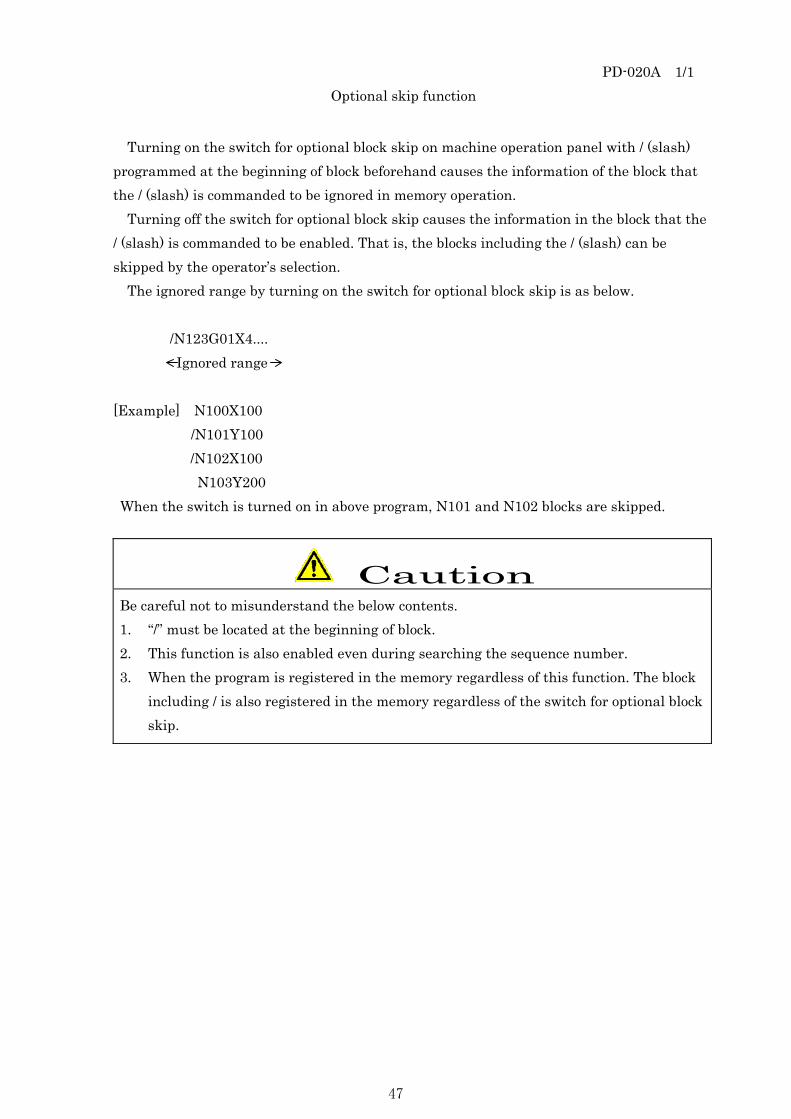
Turning on the switch for optional block skip on machine operation panel with / (slash) programmed at the beginning of block beforehand causes the information of the block that the / (slash) is commanded to be ignored in memory operation.
Turning off the switch for optional block skip causes the information in the block that the / (slash) is commanded to be enabled. That is, the blocks including the / (slash) can be skipped by the operator’s selection.
The ignored range by turning on the switch for optional block skip is as below. /N123G01X4.... Ignored range [Example] N100X100 /N101Y100
/N102X100 N103Y200
When the switch is turned on in above program, N101 and N102 blocks are skipped.
Caution
Be careful not to misunderstand the below contents. 1. “/” must be located at the beginning of block. 2. This function is also enabled even during searching the sequence number. 3. When the program is registered in the memory regardless of this function. The block
including / is also registered in the memory regardless of the switch for optional block skip.
47

PD-050A 1/2 Incremental / Absolute command
The methods for commanding the program for this machine have 2 ways to command as incremental and absolute (value). 1. Incremental command
It is the method to command in turn with; always putting the start point as zero point of program and programming the movement value of coordinate for the point where is moved subsequently in the case of indicating the coordinate value of each point of the figure in the program.
Case of programming the sequence P1, P2, P3, P4, P5, P0, by starting from P0. P0 → P1 X+30 Y+40 P1 → P2 X+40 Y0 P2 → P3 X0 Y+40 P3 → P4 X+50 Y0 P4 → P5 X0 Y-80 P5 → P0 X-120 Y0
40 50
+Y
P0
P1 P2
P3
P5
P4
80
120
30
40
-Y
-X +X
In this way, it is the method to specify the changed movement value in coordinate from present point to the point where should be moved subsequently.
48

PD-050A 2/2 Incremental / Absolute command
2. Absolute command It is the command to program the coordinate value of each point with specifying one point of the figure (P0 in this case) and assuming P0 to zero point of coordinate system in the case of indicating each point of the figure in the program.
Case of programming the sequence P1, P2, P3, P4, P5, P0, by starting from P0. P0 → P1 X+30 Y+40 P1 → P2 X+70 Y+40 P2 → P3 X+70 Y+80 P3 → P4 X+120 Y+80 P4 → P5 X+120 Y0 P5 → P0 X0 Y0
+Y
P0
P1 P2
P3
P5
P4
120 30
40
-Y
-X +X 30 70
In this way, it is the method to specify the coordinate value from specified zero point to the point where should be moved subsequently.
49

PD-060A 1/2 Beam diameter compensation
In the case of cutting, the kerf width is existed in the cutting part without fail. Example: In the case of cutting a plate in 100 × 100 square The machine moves along a square pattern of 100mm x 100mm. However, the actual result is a square plate of 99.85mm x 99.85mm and a square hole of 100.15mm x 100.15mm (Case that the kerf width is 0.15mm).
G01 Y100. X100. Y-100. X-100. 99.85
100
100.15
To cut a square plate of exactly 100mm × 100mm or a square hole of accurately 100mm × 100mm, the values in program may be increased or decreased. However, this method causes the programming complicated. The function of beam diameter compensation causes the machine to automatically increase or decrease its moving distance so as to compensate for kerf. To cut a square plate of 100mm × 100mm, in the case of moving with shifting only a half of kerf in the left side of cutting direction in the program commanded in 100 ×100, the torch moves at more than the distance of 100 ×100. As a consequence of above correction, the machine motion becomes larger than 100 ×100 and the obtained plate will be sized exactly 100 ×100.
Product
100
50

PD-060A 2/2 Beam diameter compensation
On the other hand, to obtain the inner square hole of 100 × 100, the torch must be moved with shifting a half of kerf width in the right side of cutting direction in the program commanded with 100 × 100
Product
In this way, it is necessary to execute the kerf compensation in the specified program for actual cutting.
Kerf compensation is applied to the left of the cutting direction in the case that the product is at the right side of the cutting direction and the scrap is at the left side of the cutting direction.
Also, in the case that the product is at the left side of the cutting direction and the scrap is at the right side, kerf compensation is applied to the right side.
51

PD-070B 1/2 Corner process
Corner process Create the corner process program with considering what the corner of product is processed (the corner rounded, the corner squared up) or the cutting time. 1. The corner is rounded.(Mild steel, Stainless steel)
Commanding R at the corner causes the corner to become round. *Minimum R value might change depending on the plate thickness or the kind of material. a) [Feature]
The cutting time becomes faster than that of minute process or corner acceleration/deceleration. The out of order is occurred at the corner. (It is not square.)
b) Program type (Process condition)
1
1 1
100m
100mm
G01Y98. Straight line G02X2.Y2.I2. Rounded corner G01X98. Straight line
2. Corner dwell (Mild steel, Stainless steel)
Dwelling (commanding G04) at the corner causes to reduce the out of order at the corner. a) [Feature]
The out of order at the corner is reduced compared with the unprocessed corner program. Moreover, in the case of mild steel cutting, the material is easily to notched compared with the minute process because the machine stops at the corner temporarily
b) Form of program(Process condition)
1
1
100mm
100mDwell
G01Y100. Straight line G04X1. Dwell G01X100. Straight line
In the case of SUS stainless steel with the thickness 16mm or less, dwell at the corner. In the case of SUS stainless steel with the thickness 16mm or more, do not dwell at the corner but process the corner rounded.
52

PD-070B 2/2 Corner process
3. Minute process (Only Mild steel cutting) Applying the minute process (about 2mm ramped up) to the corner causes the corner to be squared up. Moreover, after minute process, cut the material with decelerating for 3mm. a) [Feature]
The corner gets right angle compared with that of corner acceleration/deceleration. The cutting time becomes longer depending on the minute process with deceleration or assist gas pressure change (settling time).
b) Program type (Process condition)
1
1 4
100mm
100mm
G1Y100. Straight line SPF_E_CODE (4) For Minute process G01X2. For Minute process SPF_E_CODE (1) For Straight line G01X98. Straight line
(Note2) Change the velocity “n” according to just before E* command. Just before cutting chart No. 1 2 3 4 5 F command to return velocity Velocity 1 Velocity 2 Velocity 3 Velocity 4 Velocity 5 Just before cutting chart No. 6 7 8 9 10 F command to return velocity Velocity 6 Velocity 7 Velocity 8 Velocity 9 Velocity 10
53

PD-080A 1/1 Radial error for circular arc
Radial error for circular arc
The relationship between the circular arc cutting velocity and tolerance value due to servo error can be expressed by the formula as below.
Δr : Maximum value of radial error (mm) V : Feed velocity (mm/sec) r : Arc radius (mm) Kp : Positional loop gain
Actual path
Specified path
Δr
r
Δr = (V * V) / (2* r Kp * Kp) ・・・・・ ① (Example) When the above formula ① is calculated with using Radius r = 50.0mm, Loop gain Kp = 40, Velocity V = 50mm/sec, the tolerance value Δr is 0.0156mm.
Δr = (50 * 50) / (2 * 50 * 40 * 40) = 0.0156mm When the above formula ① is calculated with using Radius r = 5.0mm, Loop gain Kp = 40, Velocity V = 50mm/sec, the tolerance value Δr is 0.000156.
Δr = (5 * 5) / (2 * 50 * 40 * 40) = 0.000156mm When the above formula ① is calculated with using Radius r = 5.0mm, Loop gain Kp = 4, Velocity V = 50mm/sec, the tolerance value Δr is 0.0156mm.
Δr = (5 * 5) / (2 * 50 * 4 * 4) = 0.0156mm
The above shows the relation between the positional loop gain and radial error. As for the actual process, the track at the tip of tool is changed depending on the influence of speed loop gain according to the machine stiffness.
54

PD-090A 1/1 Speed control for small circular arc
Speed control for small circular arc Curved acceleration rate factor Machine data MD20602 CUVC_EFFECT_ON_PATH_ACCEL The curved section consisting of minute linear at circular arc cutting is controlled so that
the sum added tangent direction component of acceleration rate and centrifugal force component corresponds to MD32300. At this time, decelerate the acceleration rate at the curved section according to Tangent direction component: MD32300 * (1.0 - MD20602).
Decelerate the feed velocity at the curved section according to Centrifugal force component: MD32300 * MD20602.
In the case that the speed is high at the small radial arc corner and the machine oscillation due to the centrifugal force, lowering this value setting causes to the speed to lower and the oscillation to be suppressed.
Setting value 0.0 ~ 0.95 However, in the case that the setting value is 0.0, the speed control is disabled.
Related MD MD32300 MAX_AX_ACCEL Acceleration deceleration speed
Setting unit [m/S2]
Caution Be careful not to misunderstand the below contents.
It is the theoretical approximate value for NC and the operation check at the actual machining is required.
55

PD-110E 1/2 Laser power command
1. Laser power command ON (SPF_LASER_ON) Set the laser power with keeping the values of laser frequency and duty according to the cutting chart number of cutting chart table.
Command format
SPF_LASER_ON (1, 4) Cutting chart No. 4 (Example) Piercing type (Quick) 1 Piercing type (HSQ) 2 Punch piercing (for punching) 4 After punching (punch cutting) 5 Oxygen piercing 6 Oxygen piercing small circle 7 Nitrogen piercing 8 Nitrogen piercing small circle 9
Motion: Torch down, Assist gas ON, Beam ON, Height control ON
56

PD-110E 2/2 Laser power command
2. Laser power command OFF (SPF_LASER_OFF) Command format
SPF_LASER_OFF ( 0 ) 0 is fixed.
Motion: Beam OFF, Assist gas OFF, Torch up
Caution
1. SPF_LASER_ON and SPF_LASER_OFF are commanded in the NC program.
57

PD-115E 1/5 Process condition setting function
1. Process condition setting function (SPF_COND)
Register the group of cutting chart data requiring for laser process (data table group by process material which items are combined) with the specified data area with titling (Material + Plate thickness). When this title is specified in the program, the corresponding cutting chart data group is loaded. Then commanding the data number adapting the process contents causes the process data (cutting chart) to be loaded and then the laser process is performed. This function can set the condition requiring for the process according to only specifying the data number. Also not changing the cutting chart in the host program station but changing or adjusting the data table in the factory side (each machine side) causes the laser process to be performed.
2. Loading the group of cutting chart data It is necessary to specify the process material (title) at the beginning of each process in the program and then load the group of cutting chart data. Specify the process material according to the comment in parenthesis following SPF_COND (1, 1,12.0 ,0). That is, the comment corresponds to the title. The comment is a type SPF_COND (I, H, BB.B, CC). “I” means material or process number, “H” means surface treatment, “BB.B” means plate thickness mm, “CC” means initial motion and “,” means the separator between the former item and following item. (Command the plate thickness at this time by mm until the last digit.)
58

PD-115E 2/5 Process condition setting function
SPF_COND (1 , 0, 12.0 , 0) Bevel angle (Not used) 0 Plate thickness mm Surface 0 Not specified Surface 101 Zinc Surface 102 Wash Material No. 1 SS400P Material No. 2 SS400C, etc
a) The materials in initial state for process condition table are prepared as below.
Add the material as necessary. 1. Mild steel: Pulse cutting (1, * ,**.* , 0) SS400P 2. Mild steel: CW cutting (2, *, **.* , 0) SS400C 3. Mild steel: Pulse cutting (3, *, **.* , 0) SM490A 4. Stainless: N2 cuttingφ3 Nozzle(4, *, **.* , 0) SUS304N3 ※Option 5. Stainless: N2 cuttingφ5 Nozzle(5, *, **.* , 0) SUS304N5 ※Option 6. Stainless: N2 cuttingφ6 Nozzle(6, *, **.* , 0) SUS304N6 ※Option 7. Unavailable (7, *, **.* , 0) 8. Unavailable (8, *, **.* , 0) 9. Aluminum: N2 cutting (9, *, **.* , 0) ALUMI ※Option 10. High tensile steel plate (10, *, **.* , 0) H-steel plate ※Option 11. to 100. Arbitrary material is creatable
(11 ~ 100, *,**.*,0) Laser marking (Material ,0 ,0.0, 0) L.MARK Removal of coating (Zinc) (0, Surface, 0.0, 0) Surface No. 101 Removal of coating (Wash) (0, Surface, 0.0, 0) Surface No. 102
b) Surface 1. Zinc 101 2. Wash 102
59

PD-115E 3/5 Process condition setting function
c) The plate thickness in initial state for process condition table is prepared as below. Add the plate thickness as necessary.
① Mild steel 3.2mm,4.5mm,6.0mm,9.0mm,12.0mm,14.0mm,16.0mm,19.0mm,22.0mm,25.0mm
② Stainless steel (O2 cutting) ※Optional 1.5mm,2.0mm,2.5mm,3.0mm,4.0 ~ 12.0mm(1mm pitch)
③ Stainless steel (N2 cutting) ※Optional 1.5mm,2.0mm,2.5mm,3.0mm,4.0 ~ 16.0mm(1mm pitch)
④ Aluminum steel (N2 cutting) ※Optional 1.5mm,2.0mm,2.5mm,3.0mm,4.0 ~ 16.0mm(1mm pitch)
⑤ Laser marking (O2 or N2 cutting)※Optional Common all plate thickness
⑥ Removal of coating Common all plate thickness
Note
The plate thickness for Laser marking and Removal of coating shall be set to “0.0”. Input the thickness value in **.*. Example) For Pulse cutting for mild steel t12, SPF_COND (1,0,12.0,0)
60

PD-115E 4/5 Process condition setting function
3. Process data setting Cutting chart data table for process data is provided. Cutting chart No. 1-10
1 to 10 in Detail are cutting chart number. Normal cutting (1) Lead-in (2) Mild steel: Blank (3) SUS: Lead-in (SUS) (3) (Lead-in in SUS cutting when the small circle is existed) Mild steel: Minute cut. (4) SUS: SUS S. circle cutting (4) (Small circle cutting after piercing) Small area 5R (5) Small area 10R (6) Small area 20R (7) Small area 40R (8) Small area 80R (9) Blank (10)
61

PD-115E 5/5 Process condition setting function
Example of program File name ****.MPF G291 ISO mode (necessary) G92X0.Y0 Coordinate system setting (necessary) G91 Incremental SPF_COND (1,101,12.0,0) Loading the group of data table suitable for process material, Surface and process conditions N0 Start position (necessary) N****G00X30.Y30 Sequence No. and Positioning SPF_LASER_ON (1,1) Piercing program (Piercing type, Cutting chart number) (Torch down, Assist gas ON, Beam ON, Height control ON) G41G01X-6.Y0.D21 Kerf compensation ON : : G40G01X0.Y-2.5 Kerf compensation OFF SPF_LASER_OFF (0) Cutting end code (Beam OFF, Assist gas OFF, Torch up) SPF_PROG_END (0) Automatic operation end G290 Siemens mode (necessary in schedule operation) M30 Program end (necessary)
[Cautions] The extension of program name should be .MPF.
62

PD-181A 1/1 Command at lead-out
1. Hold command at lead-out and Touch alarm disabled (SPF_T_HOLD) In the case that the lead-out of product is overlapped the lead-in part, putting the torch into the lower direction is occurred in height control motion depending on the cutting shape and the touch alarm is easily to occurred. Therefore, command SPF_T_HOLD (n) to execute the Hold command and Touch alarm disabled command in short of lead-out linear block a few mm short of edge. Or consider that the product can drop from cutting table at inner contour cutting.
Command format SPF_T_HOLD ( n )
n’s unit is mm. Motion: Hold ON, Touch alarm disabled
2. Example of program at lead-out
The command at lead-out shall be the below program method.
Program method : : SPF_T_HOLD(5) Hold process
Command the Hold and Touch alarm disabled from 5mm short of block
G01X0.Y-100. G01X0Y-2.5. Lead-out SPF_LASER_OFF (0) Cutting end code (Beam OFF, Assist gas OFF, Torch up)
Product
Start point
Lead-out
Product
About 5mm
63
PD-184A 1/2 Method of cutting thick plate
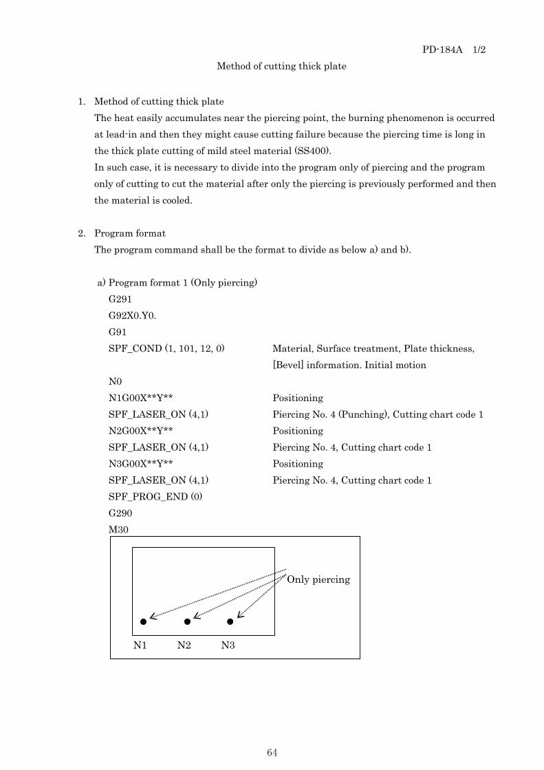
1. Method of cutting thick plate The heat easily accumulates near the piercing point, the burning phenomenon is occurred at lead-in and then they might cause cutting failure because the piercing time is long in the thick plate cutting of mild steel material (SS400). In such case, it is necessary to divide into the program only of piercing and the program only of cutting to cut the material after only the piercing is previously performed and then the material is cooled.
2. Program format The program command shall be the format to divide as below a) and b). a) Program format 1 (Only piercing)
G291 G92X0.Y0. G91 SPF_COND (1, 101, 12, 0) Material, Surface treatment, Plate thickness, [Bevel] information. Initial motion N0 N1G00X**Y** Positioning SPF_LASER_ON (4,1) Piercing No. 4 (Punching), Cutting chart code 1 N2G00X**Y** Positioning SPF_LASER_ON (4,1) Piercing No. 4, Cutting chart code 1 N3G00X**Y** Positioning SPF_LASER_ON (4,1) Piercing No. 4, Cutting chart code 1 SPF_PROG_END (0) G290 M30
Only piercing
N1 N2 N3
64

PD-184A 2/2 Method of cutting thick plate
b) Program format 2 (Only cutting) G291 G92X0.Y0. G91 N0 SPF_COND (1, 101, 12, 0) Material, Surface treatment, Plate thickness, [Bevel] information. Initial motion N1G00X**Y** Positioning SPF_LASER_ON (5,1) Piercing No. 5 (Punching), Cutting chart code 4 G01Y** Lead-in : : SPF_LASER_OFF (0) G00X**Y**. ..... ..... ..... ..... SPF_PROG_END (0) G290 M30
Only cutting
N1 N2 N3
65

66

PE-000 1/1
P E
PROGRAM CONFIGURATION
67

PE-002A 1/3 Program configuration
1. Entire program configuration Entire structure of process program is approximately as below. The details for each item will be described after the 2nd item.
Beginning information
Marking data
Cutting data
End information
68

PE-002A 2/3 Program configuration
2. Beginning information shall be as below. Moreover, all parameter to use for beginning information shall be commanded without decimal point. a) G291 b) G92X0.Y0. c) G90 or G91 d) SPF_COND (A,B,C,D)
For a) It is ISO mode command. Usually G291 is commanded For b) commands the zero point in workpiece coordinate system For c) selects whether to create the program format either of Absolute command (G90) or Incremental command (G91) For d) It is material information command. A Material number (Cutting method)
1:SS400P 2:SS400C
B Surface number (In the case that the removal of coating is not performed, input 0.) 101: Zinc 102: Wash
C Plate thickness D Bevel angle (Not used) Input 0.
69

PE-002A 3/3 Program configuration
3. Marking data a) The line marking program shall be as the separated sample program.
4. Cutting data The cutting program shall be as the separated sample program.
5. End information It shall be as below. a) SPF_PROG_END () b) G290 c) M30 For a) It is a program end code such as each I/O OFF and Internal variable clear and commands SPF_PROG_END(). For b) commands the End of tape (End of program).
70

PE-040A 1/5 Main program and sub program
1. Main program The program is divided into Main program (.MPF) and Sub program (.SPF). Usually, though the CNC activates with following the main program, when the call up command such as [Follow the sub program instruction] is programmed in the main program, the after CNC follows the instruction of sub program. Or when the end command such as [Return to the main program instruction] is programmed in the command of sub program, the after CNC follows the instruction of main program.
Main program Sub program Command 1 Command 1’ Command 2 Command 2’
SUB PROGRAM NAME
Command n Command n + 1 M17 or RET
(Return to the main program instruction)
Select one main program to operate the machine with following that command.
71

PE-040A 2/5 Main program and sub program
2. Sub program (.SPF) In the case that there are some fixed sequence or repetition pattern in the program, when either of them are registered with the memory as sub program beforehand, it can be extremely easy to program. The sub program is called up from memory card. Also the called sub program calls up other sub program. When it is assumed that the sub program called up from main program is counted as single called sub program, it is possible to call up to eightfold ones.
Main program Sub program Sub program G291 SPF_LASER_ON SPF_LASER_ON_H
SPF_LASER_ON_H
SPF_LASER_ON
M30 M17 M17
(Nesting single) (Nesting double) (Nesting triple)
Once the call up command causes to repeat calling up sub program continuously. The call up command once causes to repeat up to 9999 times.
72

PE-040A 3/5 Main program and sub program
3. Creation of sub program 1 sub program consists of the format as below.
PROC SPF_XXXX Sub program name
Sub program
M17
In the sub program that should take over the parameter from the call program, give the sub program name following PROG at the beginning of sub program. M 17 is commanded at the last of sub program. It is also possible to use RET instead of M17 at the last of sub program. Refer to the instruction manual for the method to register the sub program with the memory.
73

PE-040A 4/5 Main program and sub program
4. Execution of sub program The sub program is called up from main program or host sub program and then executed. The method to call up sub program is as below.
SPF_XXXX P 999 Number of repetition call times
Sub program name
When the number of repetition times is omitted, the Number of repetition call times is once. Example) SPF_TEST P5 The above means the command “Call up sub program with sub program name SPF_TEST for 5 times continuously”. In the case of calling up the sub program from sub program, perform as well as the case of calling up the sub program from main program.
Caution Be careful not to misunderstand the below contents. 1. When the specified sub program name is not found in address P,
an alarm (14011) is occurred.
74

PE-040A 5/5 Main program and sub program
5. Particular using The below particular using is available. a) When M99 is executed in the main program, the program is returned to the
beginning of main program. For example, when /M99 is inserted into the suitable part in the main program beforehand and the optional block skip is executed in OFF state, M99 is executed. When M99 is executed, the program returns to the beginning of main program and then the execution repeats from the beginning again. While the optional block skip is turned off, repeating the execution again and again and then turning on the optional block skip cause the block of /M99 to be skipped and then the program to continue to execute from the next block. In this case, if /M99Pn; is commanded, the program does not return to the beginning but returns to the sequence number “n”. It takes several time to return to the sequence number “n”.
N0010…………………; N0020…………………; N0030…………………; N0040…………………; N0050…………………; N0060…………………; /N0070 M99 P0030 ; Optional block N0080…………………; skip ON N0090 M30 ;
Opt
iona
l blo
ck s
kip
OFF
Caution Be careful not to misunderstand the below contents. 2. In the case that the rotation command, etc is included in the repeated
program, execute that command. For example, in the case that the 90 degrees rotation command is included, the degrees turn to 180 degrees at repeating twice.
75

76

PF-000 1/1
P F
EXAMPLE OF PROGRAM
77

PF-160A 1/2 Example of program (Laser marking)
1. Example of laser marking program (Process condition) a) Though this example of program provides the start point under right in the
mathematical coordinates, the start point is depending on the specification.
Positioning Laser marking
100
+Y-axis
+X-axis
SP
100
78

PF-160A 2/2 Example of program (Laser marking)
Laser marking shall be as below procedure. Example of program (1) G291 ISO mode (2) G92X0.Y0. Coordinate system setting (3) G91 Incremental (4) SPF_COND(1,0,0,0) Material, Surface treatment, Plate thickness,
[Bevel] information. Initial motion The value in ( ) changes depending on the material.
(5) N0 Start position (6) N****G00X-30.Y30. Sequence No. and Positioning (7) SPF_LMARK_ON() Beam ON ready. Beam ON (8) G01X-100.Y0. (9) G01X0.Y100. (10) G01X100.Y0. Laser marking profile (11) G01X0.Y-100. (12) SPF_LMARK_OFF() Beam OFF, Assist gas OFF, Torch up (13) SPF_PROG_END() Automatic operation end (14) G290 Siemens mode (in Schedule operation) (15) M30 End of program [Cautions] 1. In the case that the laser marking is repeated, repeat from (7) to (12). 2. The cutting chart of laser marking is set in the Laser marking of Laser condition setting
function.
79

PF-161A 1/2 Example of program (Punch marking)
1. Example of punch marking program (Process condition) a) Though this example of program provides the start point under right in the
mathematical coordinates, the start point is depending on the specification.
Positioning Punch marking
100
+Y-axis
+X-axis
SP
100
80

PF-161A 2/2 Example of program (Punch marking)
Punch marking shall be as below procedure. Example of program %; % and EOB at the beginning of program O****; Program number (1) G91; Incremental (2) G92X0Y0U0; Coordinate system setting
In the case of using the item (3) Coordinate rotation function, it can be omitted.
(3) G65P9013A*****B*****; Calling up the coordinate rotation function (4) /8M99; Using at schedule operation (5) G00X-30.Y30. ; Positioning (6) M98P8800; Calling up the punch marking (7) G00X-100. ; Positioning (8) M98P8800; Calling up the punch marking (9) G00Y100. ; Positioning (10) M98P8800; Calling up the punch marking (11) G00X100. ; Positioning (12) M98P8800; Calling up the punch marking (13) /9M99 ; Using at schedule operation (14) M90 ; Automatic power-off (15) M02 End of program
% [Cautions] 1. In the case that the punch marking is repeated, repeat from (5) to (12). 2. Call up the punch marking with [M98P8800]. 3. It is not necessary to command the Torch up because the Torch up is executed in O8800.
81

PF-162A 1/1 Example of program (Marking)
Example of program G92X0.Y0. Coordinate system setting SPF_COND(1,0,0,0) Initial setting G00X**Y** Positioning F24000 Marking speed SPF_PMARK_ONOFF(1) After offset moving, Marking preheat ON SPF_MPOWDER_ONOFF(1) Marking powder ON G01X**Y** Marking program SPF_MPOWDER_ONOFF(0) Marking powder OFF G00X**Y** Positioning SPF_MPOWDER_ONOFF(1) Marking powder ON G01X**Y** Marking program SPF_MPOWDER_ONOFF(0) Marking powder OFF SPF_PMARK_ONOFF(0) After Marking preheat OFF, Offset moving SPF_PROG_END() Automatic operation end G290 Siemens mode (in Schedule operation) M30 End of program [Note] 1. ** means the data.
82

PF-170A 1/3 Example of program (Process condition)
1. Example of laser cutting program (In the case of rounded corner with 1R) a) SS400 material Plate thickness: 12mm b) Product with 100mm square c) Lead-in: 10mm, Lead-out: 5mm d) TRUMPF laser e) Process condition setting function f) Though this example of program provides the start point under right in the
mathematical coordinates, the start point is depending on the specification.
Positioning Cutting
100
+X-axis
SP
100
+Y-axis
1R
83

PF-170A 2/3 Example of program (Process condition)
Oxygen cutting of SS400 material for laser cutting shall be as below procedure. Example of program (1) G291 ISO mode (required) (2) G92X0.Y0. Coordinate system setting (required) (3) G91 Incremental (4) SPF_COND(1,0,12.0,0) Material, Surface treatment, Plate thickness,
[Bevel] information. Initial motion The value in ( ) changes depending on the material.
(5) N0 Start position (required) (6) N****G00X-30.Y30. Sequence No. and Positioning (7) SPF_LASER_ON(1,1) Piercing program
(Piercing type, Cutting chart number) (Torch down, Assist gas ON, Height control ON) (8) G41G01X-6.Y0.D21 Kerf compensation ON (9) G01X-4.Y0. (10) G01X-99.Y0. (11) G02X-1.Y1.I0.J1. (12) G01X0.Y98. (13) G02X1.Y1.I1.J0. Cutting profile (14) G01X98.Y0. (15) G02X1.Y-1.I0.J-1. (16) SPF_T_HOLD(5) Hold process Command the Hold and Touch alarm disabled at
the rest distance of next block in ( ) (17) G01X0.Y-99. (18) G01X0Y-2.5. (19) G40G01X0.Y-2.5 Kerf compensation OFF
(Note) Include the pre-cutting movement (20) SPF_LASER_OFF(0) Cutting end code
(Beam OFF, Assist gas OFF, Torch up) (21) SPF_PROG_END(0) Automatic operation end (22) G290 Siemens mode (required at schedule operation) (23) M30 End of program (required)
84

PF-170A 3/3 Example of program (Process condition)
[Cautions] 1. In the case of repeating the cutting, repeat from (7) to (20). 2. Input the movement value at commanding the Kerf compensation ON/OFF more than the
compensation value. 3. Insert D21 into the same block at commanding the Kerf compensation ON/OFF. 4. After movement block (8) moves 5mm, the Height control ON is started.
In the case that the movement is short, the Height control ON is started just before the end of movement (8).
5. When the movement value (17) is shorter than the specified value in (16), the Hold and Touch alarm disabled are not activated. In the case that the movement value (17) is short, reduce the value (16) or input [0] (Execute the Hold and Touch disabled at that time).
85

PF-171A 1/3 Example of program (Process condition)
1. Example of laser cutting program (In the case that the corner part is processed in minute.) a) SS400 material Plate thickness: 12mm b) Product with 100mm square c) Lead-in: 10mm, Lead-out: 5mm d) TRUMPF laser e) Process condition setting function f) Though this example of program provides the start point under right in the
mathematical coordinates, the start point is depending on the specification.
Positioning Cutting
100
+X-axis
SP
100
+Y-axis
86

PF-171A 2/3 Example of program (Process condition)
Oxygen cutting of SS400 material for laser cutting shall be as below procedure. Example of program (1) G291 ISO mode (required) (2) G92X0.Y0. Coordinate system setting (required) (3) G91 Incremental (4) SPF_COND(1,0,12.0,0) Material, Surface treatment, Plate thickness,
[Bevel] information. Initial motion The value in ( ) changes depending on the material.
(5) N0 Start position (required) (6) N****G00X-30.Y30. Sequence No. and Positioning (7) SPF_LASER_ON(1,4) Piercing program
(Piercing type 1(Quick), E code number) (8) G41G01X-6.Y0.D21 Minute lead-in, Kerf compensation ON (9) SPF_E_CODE(1) Cutting condition change (for Usual cutting) (10) G01X-2.Y0. (11) G01X-2.Y0. (12) G01X-100.Y0. (13) SPF_E_CODE(4) Cutting condition change (for minute) (14) G01X0.Y2. Minute process (15) SPF_E_CODE(1) Cutting condition change (for usual cutting) (16) G01X0.Y98. Usual cutting (17) SPF_E_CODE(4) Cutting condition change (for minute) (18) G01X2.Y0. Minute process (19) SPF_E_CODE(1) Cutting condition change (for usual cutting) (20) G01X98.Y0. Usual cutting (21) SPF_E_CODE(4) Cutting condition change (for minute) (22) G01X0.Y-2. Minute process (23) SPF_E_CODE(1) Cutting condition change (for usual cutting) (24) SPF_T_HOLD(5) Hold process
Command the Hold and Touch alarm disabled at the rest distance of next block in ( )
(25) G01X0.Y-98. Usual cutting (26) G01X0.Y-2.5
87

PF-171A 3/3 Example of program (Process condition)
(27) G40G01X0.Y-2.5 Kerf compensation OFF (Note) Include the pre-cutting movement
(28) SPF_LASER_OFF(0) Cutting end code (Beam OFF, Assist gas OFF, Torch up)
(29) SPF_PROG_END(0) Automatic operation end (30) G290 Siemens mode (required at schedule operation) (31) M30 End of program (required)
[Cautions] 1. In the case of repeating the cutting, repeat from (7) to (28). 2. Input the movement value at commanding the Kerf compensation ON/OFF more than the
compensation value. 3. Insert D21 into the same block at commanding the Kerf compensation ON/OFF. 4. After movement block (8) moves 5mm, the Height control ON is started.
In the case that the movement is short, the Height control ON is started just before the end of movement (8).
5. When the movement value (25) is shorter than the specified value in (24), the Hold and Touch alarm disabled are not activated. In the case that the movement value (24) is short, reduce the value (24) or input [0] (Execute the Hold and Touch disabled at that time).
88

PF-172A 1/3 Example of program (Removal of coating) (Process condition)
1. Example of removal of coating program for primer in laser cutting a) TRUMPF laser b) Process condition setting function c) Though this example of program provides the start point under right in the
mathematical coordinates, the start point is depending on the specification.
Positioning Removal of coating
100
+Y-axis
+X-axis
SP
100
89

PF-172A 2/3 Example of program (Removal of coating) (Process condition)
Removal of zinc coating process for laser cutting is as below procedure. Example of program (1) G291 ISO mode (required) (2) G92X0.Y0. Coordinate system setting (required) (3) G91 Incremental (4) SPF_COND(0,101,0.0,0) Material, Surface treatment, Plate thickness,
[Bevel] information. Initial motion The value in ( ) changes depending on the material.
(5) N0 Start position (required) (6) N****G00X30.Y30. Sequence No. and Positioning (7) SPF_LSAKI_ON(0) Removal of coating start code
(Torch down, Assist gas ON, Height control ON) (8) G41G01X-5.Y0. D21 Kerf compensation ON (9) G01X-5.Y0. (10) G01X-100.Y0. (11) G01X0.Y100. (Removal of coating profile) (12) G01X100.Y0. (13) G01X0.Y-100. (14) G01X0.Y-2.5 (15) G40G01X0.Y-2.5 Kerf compensation OFF
(Note) Include the pre-cutting movement (16) SPF_LSAKI_OFF(0) Removal of coating end code
(Beam OFF, Assist gas OFF, Torch up) (17) SPF_PROG_END(0) Automatic operation end (18) G290 Siemens mode (required at schedule operation) (19) M30 End of program (required)
90

PF-172A 3/3 Example of program (Removal of coating) (Process condition)
[Cautions] 1. In the case of removal of coating, repeat from (7) to (16). 2. Input the movement value at commanding the Kerf compensation ON/OFF more than the
compensation value. 3. Insert D21 into the same block at commanding the Kerf compensation ON/OFF. 4. Set the cutting chart prior removal of coating for zinc material with process condition
setting function (0,101,0.0,0). 5. Set the cutting chart prior removal of coating for wash material with process condition
setting function (0,102,0.0,0).
91

PF-173A 1/3 Example of program (Process condition)
1. Example of program for laser cutting (for Oxygen piercing, Nitrogen cutting) a) SUS304 material Plate thickness: 12mm b) Product with 100mm square c) Lead-in: 10mm, Lead-out: 5mm, No small circle d) TRUMPF laser e) Process condition setting function f) Though this example of program provides the start point under right in the
mathematical coordinates, the start point is depending on the specification.
Positioning Cutting
100
+X-axis
SP
100
+Y-axis
92

PF-173A 2/3 Example of program (Process condition)
Oxygen piercing and Nitrogen cutting for SUS304 material in laser cutting shall be as below procedure.
Example of program (1) G291 ISO mode (required) (2) G92X0.Y0. Coordinate system setting (required) (3) G91 Incremental (4) SPF_COND(4,0,12.0,0) Material, Surface treatment, Plate thickness,
[Bevel] information. Initial motion The value in ( ) changes depending on the material.
(5) N0 Start position (required) (6) N****G00X-30.Y30. Sequence No. and Positioning (7) SPF_LASER_ON(6,3) Oxygen piercing program,
Initial lead-in cutting chart (Oxygen piercing 6, No small circle, Cutting chart No. 3 (Initial lead-in)
(8) G41G01X-6.Y0.D21 Kerf compensation ON (9) SPF_E_CODE(2) Cutting condition change (for lead-in) (10) G01X-5.Y0. (11) SPF_E_CODE(1) Cutting condition change (for usual cutting) (12) G01X-5.Y0. (13) G01X-100.Y0. (14) G01X0.Y100. (15) G01X100.Y0. (16) SPF_T_HOLD(5) Hold process
Command the Hold and Touch alarm disabled at the rest distance of next block in ( )
(17) G01X0.Y-100. Usual cutting (18) G01X0.Y-2.5 (19) G40G01X0.Y-2.5 Kerf compensation OFF
(Note) Include the pre-cutting movement (20) SPF_LASER_OFF(0) Cutting end code
(Beam OFF, Assist gas OFF, Torch up) (21) SPF_PROG_END(0) Automatic operation end (22) G290 Siemens mode (required at schedule operation) (23) M30 End of program (required)
93

PF-173A 3/3 Example of program (Process condition)
[Cautions] 1. In the case of repeating the cutting, repeat from (7) to (20). 2. Input the movement value at commanding the Kerf compensation ON/OFF more than the
compensation value. 3. Insert D21 into the same block at commanding the Kerf compensation ON/OFF. 4. After movement block (8) moves 5mm, the Height control ON is started.
In the case that the movement is short, the Height control ON is started just before the end of movement (8).
5. When the movement value (17) is shorter than the specified value in (16), the Hold and Touch alarm disabled are not activated. In the case that the movement value (17) is short, reduce the value (16) or input [0] (Execute the Hold and Touch disabled at that time).
94

PF-174B 1/3 Example of program (Process condition)
1. Example of program for laser cutting (for Oxygen piercing, Nitrogen cutting) a) SUS304 material Plate thickness: 20mm b) Product with 100mm square c) Lead-in: 10mm, Lead-out: 5mm, Small circle is provided. d) TRUMPF laser e) Process condition setting function f) Though this example of program provides the start point under right in the
mathematical coordinates, the start point is depending on the specification.
Positioning Cutting
100
+X-axis
SP
100
+Y-axis
95

PF-174B 2/3 Example of program (Process condition)
Oxygen piercing and Nitrogen cutting for SUS304 material in laser cutting shall be as below procedure.
Example of program (1) G291 ISO mode (required) (2) G92X0.Y0. Coordinate system setting (required) (3) G91 Incremental (4) SPF_COND(6,0,20.0,0) Material, Surface treatment, Plate thickness,
[Bevel] information. Initial motion The value in ( ) changes depending on the material.
(5) N0 Start position (required) (6) N****G00X-30.Y30. Sequence No. and Positioning (7) SPF_LASER_ON(7,2) Oxygen piercing program,
Initial lead-in cutting chart (Oxygen piercing 7, Small circle is provided, Cutting chart No. 2)
(8) G41G01X-6.Y0.D21 Kerf compensation ON (9) G01X-5.Y0. (10) SPF_E_CODE(1) Cutting condition change (for usual cutting) (11) G01X-5.Y0. (12) G01X-100.Y0. (13) G01X0.Y100. (14) G01X100.Y0. (15) SPF_T_HOLD(5) Hold process
Command the Hold and Touch alarm disabled at the rest distance of next block in ( )
(16) G01X0.Y-100. Usual cutting (17) G01X0.Y-2.5 (18) G40G01X0.Y-2.5 Kerf compensation OFF
(Note) Include the pre-cutting movement (19) SPF_LASER_OFF(0) Cutting end code
(Beam OFF, Assist gas OFF, Torch up) (20) SPF_PROG_END(0) Automatic operation end (21) G290 Siemens mode (required at schedule operation) (22) M30 End of program (required)
96

PF-174B 3/3 Example of program (Process condition)
[Cautions] 1. In the case of repeating the cutting, repeat from (7) to (19). 2. Input the movement value at commanding the Kerf compensation ON/OFF more than the
compensation value. 3. Insert D21 into the same block at commanding the Kerf compensation ON/OFF. 4. After movement block (8) moves 5mm, the Height control ON is started.
In the case that the movement is short, the Height control ON is started just before the end of movement (8).
5. When the movement value (16) is shorter than the specified value in (15), the Hold and Touch alarm disabled are not activated. In the case that the movement value (16) is short, reduce the value (15) or input [0] (Execute the Hold and Touch disabled at that time).
97

PF-175B1/3 Example of program (Process condition)
1. Example of program for laser cutting (for Nitrogen piercing, Nitrogen cutting) a) SUS304 material Plate thickness: 5mm b) Product with 100mm square c) Lead-in: 10mm, Lead-out: 5mm, No small circle d) TRUMPF laser e) Process condition setting function f) Though this example of program provides the start point under right in the
mathematical coordinates, the start point is depending on the specification.
Positioning Cutting
100
+X-axis
SP
100
+Y-axis
98

PF-175B2/3 Example of program (Process condition)
Nitrogen piercing and Nitrogen cutting for SUS304 material in laser cutting shall be as below procedure.
Example of program (1) G291 ISO mode (required) (2) G92X0.Y0. Coordinate system setting (required) (3) G91 Incremental (4) SPF_COND(4,0,5.0,0) Material, Surface treatment, Plate thickness,
[Bevel] information. Initial motion The value in ( ) changes depending on the material.
(5) N0 Start position (required) (6) N****G00X-30.Y30. Sequence No. and Positioning (7) SPF_LASER_ON(8,3) Nitrogen piercing program,
Initial lead-in cutting chart (Nitrogen piercing 8, No small circle, Cutting chart No. 3 (Initial lead-in)
(8) G41G01X-6.Y0.D21 Kerf compensation ON (9) SPF_E_CODE(2) Cutting condition change (for lead-in) (10) G01X-5.Y0. (11) SPF_E_CODE(1) Cutting condition change (for usual cutting) (12) G01X-5.Y0. (13) G01X-100.Y0. (14) G01X0.Y100. (15) G01X100.Y0. (16) SPF_T_HOLD(5) Hold process
Command the Hold and Touch alarm disabled at the rest distance of next block in ( )
(17) G01X0.Y-100. Usual cutting (18) G01X0.Y-2.5 (19) G40G01X0.Y-2.5 Kerf compensation OFF
(Note) Include the pre-cutting movement (20) SPF_LASER_OFF(0) Cutting end code
(Beam OFF, Assist gas OFF, Torch up) (21) SPF_PROG_END(0) Automatic operation end (22) G290 Siemens mode (required at schedule operation) (23) M30 End of program (required)
99

PF-175B3/3 Example of program (Process condition)
[Cautions] 1. In the case of repeating the cutting, repeat from (7) to (20). 2. Input the movement value at commanding the Kerf compensation ON/OFF more than the
compensation value. 3. Insert D21 into the same block at commanding the Kerf compensation ON/OFF. 4. After movement block (8) moves 5mm, the Height control ON is started.
In the case that the movement is short, the Height control ON is started just before the end of movement (8).
5. When the movement value (17) is shorter than the specified value in (16), the Hold and Touch alarm disabled are not activated. In the case that the movement value (17) is short, reduce the value (16) or input [0] (Execute the Hold and Touch disabled at that time).
100

PF-176B1/3 Example of program (Process condition)
1. Example of program for laser cutting (for Nitrogen piercing, Nitrogen cutting) a) SUS304 material Plate thickness: 12mm b) Product with 100mm square c) Lead-in: 10mm, Lead-out: 5mm, Small circle is provided d) TRUMPF laser e) Process condition setting function f) Though this example of program provides the start point under right in the
mathematical coordinates, the start point is depending on the specification.
Positioning Cutting
100
+X-axis
SP
100
+Y-axis
101

PF-176B2/3 Example of program (Process condition)
Nitrogen piercing and Nitrogen cutting for SUS304 material in laser cutting shall be as below procedure.
Example of program (1) G291 ISO mode (required) (2) G92X0.Y0. Coordinate system setting (required) (3) G91 Incremental (4) SPF_COND(5,0,12.0,0) Material, Surface treatment, Plate thickness,
[Bevel] information. Initial motion The value in ( ) changes depending on the material.
(5) N0 Start position (required) (6) N****G00X-30.Y30. Sequence No. and Positioning (7) SPF_LASER_ON(9,2) Nitrogen piercing program,
Initial lead-in cutting chart (Nitrogen piercing 9, Small circle is provided, Cutting chart No. 2)
(8) G41G01X-6.Y0.D21 Kerf compensation ON (9) G01X-5.Y0. (10) SPF_E_CODE(1) Cutting condition change (for usual cutting) (11) G01X-5.Y0. (12) G01X-100.Y0. (13) G01X0.Y100. (14) G01X100.Y0. (15) SPF_T_HOLD(5) Hold process
Command the Hold and Touch alarm disabled at the rest distance of next block in ( )
(16) G01X0.Y-100. Usual cutting (17) G01X0.Y-2.5 (18) G40G01X0.Y-2.5 Kerf compensation OFF
(Note) Include the pre-cutting movement (19) SPF_LASER_OFF(0) Cutting end code
(Beam OFF, Assist gas OFF, Torch up) (20) SPF_PROG_END(0) Automatic operation end (21) G290 Siemens mode (required at schedule operation) (22) M30 End of program (required)
102

PF-176B3/3 Example of program (Process condition)
[Cautions] 1. In the case of repeating the cutting, repeat from (7) to (19). 2. Input the movement value at commanding the Kerf compensation ON/OFF more than the
compensation value. 3. Insert D21 into the same block at commanding the Kerf compensation ON/OFF.
After movement block (8) moves 5mm, the Height control ON is started. In the case that the movement is short, the Height control ON is started just before the end of movement (8).
4. When the movement value (16) is shorter than the specified value in (15), the Hold and Touch alarm disabled are not activated. In the case that the movement value (16) is short, reduce the value (15) or input [0] (Execute the Hold and Touch disabled at that time).
103