Embed Size (px)
Citation preview

1
State Bank of India
RETAIL - Specification
July 2015

2
Table of Contents
Title Page
F Masonry 4
F10 Brick/ block walling 6
F30 Accessories/ sundry items for brick/ block/ stone walling 10
G Structural/Carcassing metal/timber 14
G20 Carpentry/ timber framing/ first fixing 16
K Linings/Sheathing/Dry partitioning 20
K10 Plasterboard dry linings/ partitions/ ceilings 22
K13 Rigid sheet fine linings and panelling 33
K40 Demountable suspended ceilings 36
L Windows/Doors/Stairs 42
L10 Windows/ Rooflights/ Screens/ Louvres 44
L20 Doors/ shutters/ hatches 48
L40 General glazing 54
M Surface finishes 56
M10 Cement based levelling/ wearing screeds 58
M40 Stone/ concrete/ quarry/ ceramic tiling/ mosaic 63
M50 Rubber/ plastics/ cork/ lino/ carpet tiling/ sheeting 71
M52 Decorative papers/ fabrics 78
M60 Painting/clear finishing 82
N Furniture/Equipment 86
N10 General fixtures/ furnishings/ equipment 88
N11 Domestic kitchen fittings, furnishings and equipment 96
N13 Sanitary appliances and fittings 100
N14 General signage systems 104
N15 Fire and safety signage systems 108
P Building fabric sundries 111
P10 Sundry insulation/ proofing work 113
3
P12 Fire stopping systems 115
P20 Unframed isolated trims/ skirtings/ sundry items 119
P21 Door/ window ironmongery 121
P31 Holes, chases, covers and supports for services 126
Z Building fabric reference specification 128
Z10 Purpose made joinery 130
Z11 Purpose made metalwork 133
Z20 Fixings and adhesives 137
Z21 Mortars 141
Z22 Sealants 144
Z31 Powder coatings 146
Z33 Anodizing 150

4
F
Masonry

5
F10
Brick/ block walling

6
F10 Brick/ block walling
To be read with Preliminaries/ General conditions.
TYPES OF WALLING
355 CONCRETE COMMON BLOCKWORK TO EXTERNAL CAVITY WALL CONSTRUCTION • Blocks: To BS EN 771-3. - Manufacturer: Contractor's Choice. Product reference: Contractor's Choice. - Configuration: Solid. - Compressive strength: Mean value: 7 N/mm². Characteristic value: Not applicable. Category: II. - Freeze/ Thaw resistance: Frost resistant. - Thermal properties: to BS EN 771-3. - Work sizes (length x width x height): 440 x 100 x 215 mm. - Special shapes: None. - Additional requirements: Water absorption by capillarity: to BS EN 771-3 . • Mortar: As section Z21. - Standard: To BS EN 998-2. - Mix: Group 2 as clause 460. - Additional requirements: None. Bond: Half lap stretcher.
356 CONCRETE COMMON BLOCKWORK TO INTERNAL WALL CONSTRUCTION • Blocks: To BS EN 771-3. - Manufacturer: Contractor's Choice. Product reference: Contractor's Choice. - Configuration: Solid. - Compressive strength: Mean value: 7 N/mm². Characteristic value: Not applicable. Category: II. - Freeze/ Thaw resistance: Not applicable. - Thermal properties: Not applicable. - Work sizes (length x width x height): 440 x 100 x 215 mm. - Special shapes: None. - Additional requirements: None. • Mortar: As section Z21. - Standard: To BS EN 998-2. - Mix: Group 2 as clause 460. - Additional requirements: None. Bond: Half lap stretcher.
TESTING
415 FRESH MORTAR CEMENT CONTENT • Test method: BREMORTEST in accordance with Building Research Establishment Information Paper 8/89 . • Test specimens: Test mortar for the following wall types: F10/ 355 and 356 . Results: Submit.

7
WORKMANSHIP GENERALLY
440 CONDITIONING OF CONCRETE BRICKS/ BLOCKS • Autoclaved concrete bricks/ blocks delivered warm from manufacturing process: Do not use. • Age of nonautoclaved concrete bricks/ blocks: Do not use until at least four weeks old. • Avoidance of suction in concrete bricks/ blocks: Do not wet. Use of water retaining mortar admixture: Submit details.
460 MORTAR GROUPS • Mix proportions: For a specified group select a mix design from the following: ________________________________________________________________________ Group 1 2 3 4 ________________________________________________________________________ PC*:lime:sand with or without air entraining additive 1:0-0.25:3 1:0.5-4.5 1:1:5-6 1:2:8-9 ________________________________________________________________________ Masonry cement:sand containing PC* and lime in approx ratio 1:1, and an air entraining additive - 1:3 1:3.5-4 1:4.5 ________________________________________________________________________ Masonry cement:sand containing PC* and inorganic materials other than lime and air entraining additive - 1:2.5-3.5 1:4-5 1:5.5-6.5 ________________________________________________________________________ PC*:sand and air entraining additive 1:3 1:3-4 1:5-6 1:7-8 ________________________________________________________________________ PC* = Portland cement
• Batching: Mix proportions by volume. Mortar type: Continuous throughout any one type of masonry work.
500 LAYING GENERALLY • Mortar joints: Fill vertical joints. Lay bricks, solid and cellular blocks on a full bed. • Bond where not specified: Half lap stretcher. Vertical joints in facework: Even widths. Plumb at every fifth cross joint.
520 ACCURACY • Courses: Level and true to line. • Faces, angles and features: Plumb. • Permissible deviations: - Position in plan of any point in relation to the specified building reference line and/ or point at the same level ± 10 mm. - Straightness in any 5 m length ± 5 mm. - Verticality up to 3 m height ± 10 mm. - Verticality up to 7 m height ± 14 mm. - Overall thickness of walls ± 10 mm. - Level of bed joints up to 5 m (brick masonry) ± 11 mm. - Level of bed joints up to 5 m ± 13 mm.
8
535 HEIGHT OF LIFTS IN WALLING USING CEMENT GAUGED OR HYDRAULIC LIME MORTAR • Quoins and advance work: Rack back. • Lift height (maximum): 1.2 m above any other part of work at any time. Daily lift height (maximum): 1.5 m for any one leaf.
545 LEVELLING OF SEPARATE LEAVES • Locations for equal levelling of cavity wall leaves: As follows: - Every course containing vertical twist type ties or other rigid ties. - Every third tie course for double triangle/ butterfly ties. Courses in which lintels are to be bedded.
595 LINTELS Bearing: Ensure full length masonry units occur immediately under lintel ends.
610 SUPPORT OF EXISTING WORK • Joint above inserted lintel or masonry: Fully consolidated with semidry mortar to support existing structure.
620 BLOCK BONDING NEW WALLS TO EXISTING • Pocket requirements: Formed as follows: - Width: Full thickness of new wall. - Depth (minimum): 100 mm. - Vertical spacing: Brick to brick: 4 courses high at 8 course centres. Block to block: Every other course. Pocket joints: Fully filled with mortar.
635 JOINTING Profile: Consistent in appearance.
645 ACCESSIBLE JOINTS NOT EXPOSED TO VIEW Jointing: Struck flush as work proceeds.
671 FIRE STOPPING • Avoidance of fire and smoke penetration: Fit tightly between cavity barriers and masonry. Leave no gaps.
690 ADVERSE WEATHER • General: Do not use frozen materials or lay on frozen surfaces. • Air temperature requirements: Do not lay bricks/ blocks: - In cement gauged mortars when at or below 3°C and falling or unless it is at least 1°C and rising. - In hydraulic lime:sand mortars when at or below 5°C and falling or below 3°C and rising. - In thin joint mortar glue when outside the limits set by the mortar manufacturer. • Temperature of walling during curing: Above freezing until hardened. • Newly erected walling: Protect at all times from: - Rain and snow. Drying out too rapidly in hot conditions and in drying winds.

9
F30
Accessories/ sundry items for brick/ block/ stone walling
10
F30 Accessories/ sundry items for brick/ block/ stone walling
To be read with Preliminaries/ General conditions.
CAVITIES
110 CONCRETE FILL TO BASE OF CAVITY • Concrete generally: To BS EN 206-1 and BS 8500-2. - Designated concrete: GEN 1 . Workability: High. • Extent: Maintain 75 mm between top of fill and external ground level and a minimum of 225 mm between top of fill and ground level dpc. Placement: Compact to eliminate voids.
120 CLEANLINESS Cavity base and faces, ties, insulation and exposed dpcs: Free from mortar and debris.
132 PERPEND JOINT PLASTICS WEEP HOLES • Manufacturer: Contractor's Choice as approved colour matched to external render finishes . - Product reference: Contractor's Choice as approved colour matched to external render finishes . • Locations: Through outer leaf immediately above base of cavity, at cavity trays, stepped dpcs and external openings. 75 mm above top of cavity fill at base of cavity. Provision: At not greater than 1000 mm centres and not less than two over each opening.
155 PARTIAL FILL CAVITY INSULATION • Insulation: Rock wool batts. - Standard: BS EN 13162. - Product certification: British Board of Agrement (BBA) Certificate number ???. • Manufacturer: Contractor's Choice as approved to achieve 0.25W/m2degC 'U'Value. - Product reference: Contractor's Choice as approved. • Face size (length x width): To suit wall tie spacing. • Thickness (nominal): to achieve 0.25W/m2degC 'U'Value. • Thermal conductivity: to achieve 0.25W/m2degC 'U'Value. • Reaction to fire class: A1. • Additional requirements: None. • Placement: Secure against face of inner leaf. - Residual cavity: Clear and unobstructed. • Joints between boards, at closures and penetrations: No gaps and free from mortar and debris.
180 CAVITY CLOSERSTO NEW CAVITY WALL CONSTRUCTIONS • Manufacturer: Kingspan Ltd . - Product reference: Thermabate Cavity Closer . Accessories: None .

11
REINFORCING/ FIXING ACCESSORIES
210 CAVITY WALL TIESGENERALLY • Standard: To BS 1243. - Type: Vertical twist . • Material/ finish: Steel galvanized after manufacture . Sizes: To suite new cavity width to manufacturer's written instructions .
211 CAVITY WALL TIES USED WITH PARTIAL FILL INSULATIONGENERALLY • Standard: To BS 1243. - Type: Vertical twist . • Manufacturer: Contractor's Choice. - Product reference: Contractor's Choice. • Material/ finish: Steel galvanized after manufacture . • Sizes: To suite new cavity width to manufacturer's written instructions . Tie mounted insulation retaining clips: As recommended by tie manufacturer.
233 FIXING TIES IN MASONRY CAVITY WALLS WITH PARTIAL FILL CAVITY INSULATION • Embedment in mortar beds (minimum): 50 mm. • Placement: Sloping slightly downwards towards outer leaf, without bending. Drip centred in the cavity and pointing downwards. • Spacing: Evenly space in non staggered horizontal and vertical rows. - Horizontal centres: 600 mm . - Vertical centres: 450 mm . • Spacing centres of top (eaves) row of ties: Not more than 450 mm . • Provision of additional ties: Within 225 mm of reveals of unbonded openings. Spacing: At not more than 300 mm centres vertically .
241 WALL STARTERS/ CONNECTORS • Manufacturer: Contractor's Choice . - Product reference: Contractor's Choice . • Material/ finish: Galvanized low carbon steel . Sizes: Contractor's Choice to suit individual application .
270 MESHWORK JOINT REINFORCEMENTGENERALLY • Standard: To BS EN 845-3. • Manufacturer: Contractor's Choice . - Product reference: Contractor's Choice . • Type: Expanded metal . • Material: Galvanized low carbon steel . • Width: Approximately 40-50 mm less in width than wall or leaf. • Placement: Lay on an even bed of mortar in a continuous strip with full laps at angles. Keep back 20 mm from face of external work, 12 mm back from face of internal work and finish joint to normal thickness. Lap length (minimum): 225 mm.
FLEXIBLE DAMP PROOF COURSES/ CAVITY TRAYS
320 DAMP PROOF COURSE - POLYETHYLENE • Standard: To BS 6515. • Manufacturer: Contractor's Choice . Product reference: Contractor's Choice .
12
345 SITE FORMED FLEXIBLE SHEET CAVITY TRAYS • Material: Polypropylene . • Manufacturer: Contractor's Choice . Product reference: Contractor's Choice .
390 SITE FORMED DPC/ CAVITY TRAY JUNCTIONS/ STOP ENDS • Three dimensional changes in shape: Form to provide a free draining and watertight installation. Seal laps. Alternative use of preformed junction cloaks/ stop ends: Submit proposals.
INSTALLATION OF DPCS/ CAVITY TRAYS
415 HORIZONTAL DPCS • Placement: In continuous lengths on full even bed of fresh mortar, with 100 mm laps at joints and full laps at angles. • Width: At least full width of leaf unless otherwise specified. Edges of dpc not covered with mortar or projecting into cavity. • Overlying construction: Immediately cover with full even bed of mortar to receive next masonry course. Overall finished joint thickness: As close to normal as practicable.
425 GROUND LEVEL DPCS Joint with damp proof membrane: Continuous and effectively sealed.
435 STEPPED DPCS IN EXTERNAL WALLS • External walls on sloping ground: Install dpcs not less than 150 mm above adjoining finished ground level.
445 SILL DPCS • Form and placement: In one piece and turned up at back when sill is in contact with inner leaf.
465 SEALING DPCSTO NEW WINDOW SILLS AND HEADS Overlaps and junctions: Seal with Double sided adhesive tape .
475 SITE FORMED CAVITY TRAYS • Requirements to prevent downward ingress of water: - Profiles: To match those shown on drawings. Firmly secured. - Joint treatment: Use unjointed wherever possible, otherwise lap at least 100 mm and seal to produce a free draining and watertight installation. - Horizontal cavity trays: Support using cavity closer. - Sloping cavity trays: Prevent sagging. Cleanliness: Free from debris and mortar droppings.
485 CAVITY TRAYS OVER OPENINGS AND OTHER CAVITY BRIDGINGS Length: To extend not less than 150 mm beyond ends of lintels/ bridgings.
560 VERTICAL DPCS GENERALLY • Form: In one piece wherever possible. Joints: Upper part overlapping lower not less than 100 mm.

13
570 JAMB DPCS AT OPENINGS • Joint with cavity tray/ lintel at head: Full underlap. • Joint with sill/ horizontal dpc at base: Full overlap. • Projection into cavity: Not less than 25 mm. Relationship with frame: In full contact.
MISCELLANEOUS ITEMS
830 BUILDING IN FRAMES • Preparation: Remove horns and provide support. Fixing cramps: Fully bed in mortar.
840 OPENINGS FOR FRAMES Formation: Use accurate, rigid templates to required size.

14
G
Structural/Carcassing metal/timber

15
G20
Carpentry/ timber framing/ first fixing
16
G20 Carpentry/ timber framing/ first fixing
To be read with Preliminaries/ General conditions.
GENERAL
105 TIMBER PROCUREMENT • Timber (including timber for wood based products): Obtained from well managed forests/ plantations in accordance with: - The laws governing forest management in the producer country or countries. - International agreements such as the Convention on International Trade in Endangered Species of wild fauna and flora (CITES). • Documentation: Provide either: - Documentary evidence (which has been or can be independently verified) regarding the provenance of all timber supplied, or - Evidence that suppliers have adopted and are implementing a formal environmental purchasing policy for timber and wood based products.
115 CONTRACTOR DESIGNED STRUCTURAL COMPONENTS • Design standard: To BS 5268-2. • Completion of design: Design and detail members and connections to satisfy loading requirements specified or otherwise calculable from the information given. • Design parameters: In accordance with Structural Engineers Details and Design. • Drawings: - Content: Drawings must show: Geometry of structure. Wood species and grades/ strength classes. Target/ Finished sizes of all timber sections. Joints not detailed on Engineer's drawings, their locations, and evidence as to their structural adequacy. - Submission: To Structural Engineer at least two weeks before commencement of fabrication. Copies: 2. • Compliance with design standard: Demonstrate by calculation or by prototype load testing in accordance with BS 5268-2, Section 8.
150 STRENGTH GRADING OF TIMBER • Grader: A company currently registered under a third party quality assurance scheme operated by a certification body approved by the UK Timber Grading Committee.
160 GRADING AND MARKING OF SOFTWOOD • Timber of a target/ finished thickness less than 100 mm and not specified for wet exposure: Graded at an average moisture content not exceeding 20% with no reading being in excess of 24% and clearly marked as 'DRY' or 'KD' (kiln dried). • Timber graded undried (green) and specified for installation at higher moisture contents: Clearly marked as 'WET' or 'GRN'. • Structural timber members cut from large graded sections: Regraded to approval and marked accordingly.

17
PRODUCTS
230 STRUCTURAL SOFTWOOD (STRENGTH CLASS NOT SPECIFIED)FOR INTERNAL FLOOR JOISTS, AS REQUIRED • Species and origin: Douglas fir-larch. • Grading standard: To the appropriate standard or rules for the specified grade and so marked. - Grade: GS to BS 4978. Treatment: None required.
270 UNGRADED SOFTWOODFOR FRAMINGS GENERALLY TO WORKTOPS SUPPORTS, FASCIAS AND DROP BULKHEADS AND FEATURE CEILINGS • Quality of timber: Free from decay, insect attack (except pinhole borers) and with no knots wider than half the width of the section. • Surface finish: Sawn Generally, Regularized for fascias, bulkheads and feature ceiling battens and supports. Treatment: None required.
310 STRUCTURAL PLYWOODGENERALLY TO INTERNAL FLOORS AS REQUIRED • Standard: To the relevant national standards and quality control procedures specified in BS 5268-2, and so marked. • Type: Swedish softwood plywood. • Grade: Swedish softwood plywood. • Nominal thickness/ number of plies: To suit site situation. • Finish: Sanded. Treatment: None Required.
311 NONSTRUCTURAL PLYWOODGENERALLY • Standard: To an approved national standard. • Thickness: To suit individual site situations. • Appearance class to BS EN 635: II. • Bond quality to BS EN 314-2: Class 1. • Finish: Sanded. Treatment: None required.
WORKMANSHIP GENERALLY
401 CROSS SECTION DIMENSIONS OF STRUCTURAL SOFTWOOD AND HARDWOOD • Dimensions: Dimensions in this specification and shown on drawings are target sizes as defined in BS EN 336. • Tolerances: The tolerance indicators (T1) and (T2) specify the maximum permitted deviations from target sizes as stated in BS EN 336, clause 4.3: - Tolerance class 1 (T1) for sawn surfaces. Tolerance class 2 (T2) for further processed surfaces.
402 CROSS SECTION DIMENSIONS OF NONSTRUCTURAL SOFTWOOD • Dimensions: Dimensions in this specification and shown on drawings are finished sizes. • Maximum permitted deviations from finished sizes: As stated in BS EN 1313-1: - Clause 6 for sawn sections. Clause NA.2 for further processed sections.
420 WARPING OF TIMBER • Bow, spring, twist and cup: Not greater than the limits set down in BS 4978 or BS EN 14081-1 for softwood, or BS 5756 for hardwood.

18
430 SELECTION AND USE OF TIMBER • Timber members damaged, crushed or split beyond the limits permitted by their grading: Do not use. • Notches and holes: Position in relation to knots or other defects such that the strength of members will not be reduced. Scarf joints, finger joints and splice plates: Do not use without approval.
450 MOISTURE CONTENT • Moisture content of wood and wood based products at time of installation: Not more than: - Covered in generally unheated spaces: 24%. - Covered in generally heated spaces: 20%. 20%.
451 MOISTURE CONTENT TESTING • Procedure: When instructed, test timber sections with an approved electrical moisture meter. • Test sample: Test 5% but not less than 10 lengths of each cross-section in the centre of the length. • Test results: 90% of values obtained to be within the specified range. Provide records of all tests.
510 PROTECTION • Generally: Keep timber dry and do not overstress, distort or disfigure sections or components during transit, storage, lifting, erection or fixing. • Timber and components: Store under cover, clear of the ground and with good ventilation. Support on regularly spaced, level bearers on a dry, firm base. Open pile to ensure free movement of air through the stack. Trussed rafters: Keep vertical during handling and storage.
530 PAINTED FINISHES Structural timber to be painted: Primed as specified before delivery to site.
540 CLEAR FINISHES • Structural timber to be clear finished: Keep clean and apply first coat of specified finish before delivery to site.
JOINTING TIMBER
570 JOINTING/FIXING GENERALLY • Generally: Where not specified precisely, select methods of jointing and fixing and types, sizes and spacings of fasteners in compliance with section Z20.
ERECTION AND INSTALLATION
750 MODIFICATIONS/REPAIRS • Defects due to detailing or fabrication errors: Report without delay. • Methods of rectification: Obtain approval of proposals before starting modification or remedial work. • Defective/damaged components: Timber members/ components may be rejected if the nature and/or number of defects would result in an excessive amount of site repair.
760 TEMPORARY BRACING • Provision: As necessary to maintain structural timber components in position and to ensure complete stability during construction.
19
770 ADDITIONAL SUPPORTS • Provision: Position and fix additional studs, noggings and/ or battens to support edges of sheets materials, and wall/ floor/ ceiling mounted appliances, fixtures, etc. shown on drawings • Material properties: Additional studs, noggings and battens to be of adequate size and have the same treatment, if any, as adjacent timber supports.
775 BEARINGS • Timber surfaces which are to transmit loads: Finished to ensure close contact over the whole of the designed bearing area. • Packings: Where provided, to cover the whole of the designed bearing area. - Crushing strength: Not less than timber being supported. In external locations: Rot and corrosion proof.
784 JOISTS GENERALLY • Centres: Equal, and not exceeding designed spacing. • Bowed joists: Installed with positive camber. End joists: Positioned approximately 50 mm from masonry walls.
786 JOISTS ON HANGERS • Hangers: Bedded directly on and hard against supporting construction. Do not use packs or bed on mortar. • Joists: Cut to leave not more than 6 mm gap between ends of joists and back of hanger. Rebated to lie flush with underside of hangers. Fixing to hangers: A nail in every hole.
790 STANDARD JOIST HANGERSAS REQUIRED GENERALLY. • Standard: To BS EN 845-1. • Size and type: To suit joist, design load and crushing strength of supporting construction. Material/ finish: Galvanized low carbon steel.
795 TRIMMING OPENINGS • Trimmers and trimming joists: When not specified otherwise, not less than 25 mm wider than general joists.
840 STRUTTING TO FLOOR JOISTS • Type: One of the following: - Herringbone strutting: At least 38 x 38 mm softwood. - Solid strutting: At least 38 mm thick softwood and at least three quarters of joist depth. - Proprietary metal strutting: Of approved type to suit site situation. • Fixing: Between joists as follows: - Joist spans of 2.5 to 4.5 m: One row at centre span. - Joist spans over 4.5 m: Two rows equally spaced. - Strutting must not project beyond top and bottom edges of joists. Outer joists: Blocked solidly to perimeter walls.
850 INSPECTION GENERALLY Structural timber-work: Give reasonable notice before covering up.

20
K
Linings/Sheathing/Dry partitioning

21
K10
Plasterboard dry linings/ partitions/ ceilings

22
K10 Plasterboard dry linings/ partitions/ ceilings
To be read with Preliminaries/ General conditions.
TYPES OF DRY LINING
115 METAL STUD PARTITION SYSTEMTO INTERNAL WALL PARTITIONS GENERALLY TYPE 1 PARTITIONS • Partition type: GypWall "ROBUST" partition system by British Gypsum Limited. • Partition height: Maximum 4000 mm. • Head condition: Concrete slab ________ . - Deflection allowance: 15 mm maximum . • Structural performance: - Strength grade to BS 5234-2: Heavy . Additional tests: Not required . - Air pressure and deflection: Air pressure (maximum) 200 N/m² and deflection (maximum) height ÷ 240 mm . - Other requirements: None . • Fire resistance of complete partition assembly: To BS 476-20 and -22, 30/30 minutes (Integrity/ Insulation) . • Airborne sound insulation - Laboratory measurement of complete partition assembly: - Weighted sound reduction index Rw (minimum) to BS EN ISO 717-1: Not less than 41 Rw dB . • Metal framing: Type recommended by board manufacturer to complete the partition assembly and achieve specified performance. • Insulation: Isover APR 1200 Sound Insulation to full height of partition . - Thickness: 50 mm . • Linings: 13mm DURALINE board . • Finishing: Skim coat plaster . - Primer/ Sealer: Primer to painted areas . - Accessories: Beads/ stops as recommended by board manufacturer . Other requirements: Fire stopping around services as section P12 .
155 WALL LINING SYSTEM (METAL STUDS)TO BLOCKWORK PERIMETER INTERNAL PARTY WALLS • Manufacturer: British Gypsum Limited. - Product reference: GypLyner Universal Metal framed wall lining system. • Studs: - Type: GL1 Lining Channel. - Centres: In accordance with approved specialist manufacturer's written instructions. • Cavity between wall and studs: 30 mm. • Unbraced height (maximum): Maximum 4000mm. • Head condition: Concrete slab. - Deflection allowance: 15 mm. • Insulation: Not required. - Thickness: Not required. • Vapour control layer: Not required. • Linings: Expamet mesh Ref: 2073F face fixed back to existing blockwork wall with13mm DURALINE board. • Access units: Not required. • Finishing: Skim coat plaster . - Primer/ Sealer: Primer to painted areas. - Accessories: Metal beads/ stops recommended by board manufacturer. Other requirements: Fire stopping around services as section P12.
23
205 LINING ON TIMBERTO NON-SECURE INTERNAL PARTITIONS GENERALLY TYPE 2 PARTITIONS • Background: Studs at 450 mm centres. • Metal resilient (acoustic) bars: Not required. • Linings: 13mm DURALINE Board with 50mm thick Isover APR 1200 Sound Insulation to full height of partition. - Fixing: Screws. • Finishing: Skim coat plaster.// Taped & Jointed - Primer/ Sealer: Primer to painted areas. - Accessories: Beads/ stops as clause 692. Other requirements: Fire stopping around service penetrations as section P12.
206 LINING ON TIMBERTO SECURITY INTERNAL PARTITIONS GENERALLY TYPE 3 PARTITIONS • Background: Studs at 450 mm centres. • Metal resilient (acoustic) bars: Not required. • Linings: 13mm DURALINE Board with Expamet mesh Ref: 2073F behind boards on "attack / public side" of partition with 50mm thick Isover APR 1200 Sound Insulation to full height of partition. - Fixing: Screws. • Finishing: Skim coat plaster. // Taped & Jointed - Primer/ Sealer: Primer to painted areas. - Accessories: Beads/ stops as clause 692. Other requirements: Fire stopping around service penetrations as section P12.
207 LINING ON TIMBER TO HIGH SECURITY INTERNAL PARTITIONS GENERALLY TYPE 4 PARTITIONS • Background: Double Studs at 450 mm centres. • Metal resilient (acoustic) bars: Not required. • Linings: 13mm DURALINE Board with 6mm steel sheet between double studs up to FULL HEIGHT SLAB TO SOFFIT & WHERE THERE IS A ROOM LID With 50mm thick Isover APR 1200 Sound Insulation to full height of partition. - Fixing: Screws. • Finishing: Skim coat plaster. // Taped & Jointed - Primer/ Sealer: Primer to painted areas. - Accessories: Beads/ stops as clause 692. Other requirements: Fire stopping around service penetrations as section P12.

24
215 SUSPENDED CEILING SYSTEM GENERALLY • Structural soffits: Existing Concrete Floor Slab. • Grid type: CASOLINE MF concealed grid system by British Gypsum Limited. • Structural performance: The ceiling system must safely support loads including services fittings. - Subject to wind/ upward pressure: No. - Uniformly distributed loads (maximum): 0.6 kN/m². - Additional loads/ pressures: Lighting / AC units as drawings and schedules. - Deflection (maximum) of grid between points of support: Span ÷ 400 mm. Test standard: To BS EN 13964. • Fire performance: - Fire resistance of complete floor and ceiling assembly: Not required. - Ceiling resistance: Not required. - Protection to structural beams: Not required. • Airborne sound insulation performance: - Sound insulation of complete floor and ceiling assembly: Weighted sound reduction index, Rw (minimum) to BS EN ISO 717-1: Not applicable. - Other requirements: None. • Suspension system: As recommended by the board manufacturer to complete the ceiling system and achieve specified performance. • Linings: 12.5 mm plasterboard . • Insulation: Type recommended by board manufacturer to meet specified. - Thickness: As recommended by board manufacturer to meet specified. • Access units: Required. • Finishing: Skim coat plaster. // Taped & Jointed - Primer/ Sealer: Primer to painted areas. - Accessories: Metal beads/ stops recommended by board manufacturer . • Integrated services fittings: Hangers and housings for linear luminaires. • Other requirements: Individual perimeter drop bulkheads and drop ceiling feature detailing to Architect's separate drawings.

25
216 SUSPENDED CEILING SYSTEM TO CURVED CEILING BULKHEAD DETAILS • Structural soffits: Existing Concrete Floor Slab. • Grid type: CASOLINE CURVE concealed grid system by British Gypsum Limited. • Structural performance: The ceiling system must safely support loads including services fittings. - Subject to wind/ upward pressure: No. - Uniformly distributed loads (maximum): 0.6 kN/m². - Additional loads/ pressures: Lighting as drawings and schedules. - Deflection (maximum) of grid between points of support: Span ÷ 400 mm. Test standard: To BS EN 13964. • Fire performance: - Fire resistance of complete floor and ceiling assembly: Not required. - Ceiling resistance: Not required. - Protection to structural beams: Not required. • Airborne sound insulation performance: - Sound insulation of complete floor and ceiling assembly: Weighted sound reduction index, Rw (minimum) to BS EN ISO 717-1: Not applicable. - Other requirements: None. • Suspension system: As recommended by the board manufacturer to complete the ceiling system and achieve specified performance. • Linings: 12.5 mm plasterboard . • Insulation: Type recommended by board manufacturer to meet specified performance. - Thickness: As recommended by board manufacturer to meet specified performance. • Access units: Required. • Finishing: Skim coat plaster. // Taped & Jointed - Primer/ Sealer: Primer to painted areas. - Accessories: Metal beads/ stops recommended by board manufacturer . • Integrated services fittings: Hangers and housings for linear luminaires. • Other requirements: Individual drop bulkheads and ceiling feature detailing to Architect's separate drawings.
245 CEILING LINING ON TIMBERGENERALLY • Background: Softwood Timber Carcassing to separate details. • Metal resilient (acoustic) bars: Not required. • Linings: 12.5 mm plasterboard. - Fixings: Screws. • Finishing: Skim coat plaster. - Primer/ Sealer: Primer to painted areas. - Accessories: Metal beads/ stops recommended by board manufacturer . Other requirements: None.
255 ENCASEMENT SYSTEM (METAL FRAMING)TO EXISTING STRUCTURAL COLUMNS AND SERVICE DUCTS • Manufacturer: British Gypsum. - Product reference: GYPLYNER ENCASE. • Structural members: As drawings. - Extent of protection: Columns: Four sides.. • Fire performance: - Protection to structural steel: Non Fire Rated encasement. • Framing system: Sizes and spacing of framing and fixings as recommended by the board manufacturer. • Linings: 13mm DURALINE Board. • Finishing: Skim coat plaster. // Taped & Jointed - Primer/ Sealer: Primer to painted areas. - Accessories: Metal beads/ stops recommended by board manufacturer . Other requirements: Plan dimensions of casings to be the same for all columns.
26
275 ENCASEMENT ON TIMBER FRAMINGTO EXISTING STRUCTURAL COLUMNS AND SERVICE DUCTS • Timber framework: 25 x 38 mm with noggings at 600 mm maximum centres.. • Linings: 13mm DURALINE Board. - Fixing: Screws. • Finishing: Skim coat plaster. - Primer/ Sealer: Primer to painted areas. - Accessories: Metal beads/ stops recommended by board manufacturer . Other requirements: Plan dimensions of casings to be the same for all columns.
GENERAL/ PREPARATION
305 COMPLIANCE WITH PERFORMANCE REQUIREMENTS • Testing/ Assessment: Submit UKAS accredited laboratory reports for the following: Fire resistance: Partitions (including deflection heads and doorsets) and suspended ceilings (including access units).. • Materials, components and details: As used in testing/ assessment reports. If discrepancies arise, give notice.
325 PREPARATION OF MASONRY TO RECEIVE WALL LININGS • General: Suitable to receive lining system. Redundant fixtures and services removed. Cutting, chasing and making good completed. • Holes, gaps, service penetrations, perimeter junctions and around openings: Seal. • Adhesive fixings: Prepare substrate to achieve effective bonding. - Contaminants: Remove loose material, dirt, grease, oil, paper, etc. Absorption: Control by dampening, priming or applying bonding agents as necessary.
335 ADDITIONAL SUPPORTS • Framing: Accurately position and securely fix to give full support to: - Partition heads running parallel with, but offset from main structural supports. - Fixtures, fittings and service outlets. Mark framing positions clearly and accurately on linings. - Board edges and lining perimeters, as recommended by board manufacturer to suit type and performance of lining.
375 NEW WET LAID BASES • Dpcs: Install under full width of partitions/ freestanding wall linings. Material: Bituminous sheet or plastics.
395 CONTROL SAMPLES • General: Complete areas of finished work and obtain approval of appearance before proceeding. • Type of dry lining: Ceiling K10/115, 205, 206, 207, 215 and216. Location/ Size: Submit proposals.
COMPONENTS
401 GYPSUM PLASTERBOARD • Type: To BS EN 520, type A . - Core density (minimum): 650 kg/m³. Exposed surface and edge profiles: Suitable to receive specified finish.

27
402 GYPSUM PLASTERBOARD (VAPOUR CONTROL) • Type: To BS EN 520, type A . - Core density (minimum): 650 kg/m³. - Moisture vapour resistance of backing layer (minimum): 60 MNs/g. Exposed surface and edge profiles: Suitable to receive specified finish.
403 GYPSUM PLASTERBOARD (MOISTURE RESISTANT) • Type: To BS EN 520, type H1. - Core density (minimum): 710 kg/m³. - Core: Moisture resistant. - Paper facings: Moisture resistant. Exposed surface and edge profiles: Suitable to receive specified finish.
404 GYPSUM PLASTERBOARD (IMPROVED FIRE PROTECTION) • Type: GYPROC DURALINE To BS EN 520, type F. - Core density (minimum): 800 kg/m³. - Core: Including fibres for improved cohesion. Exposed surface and edge profiles: Suitable to receive specified finish.
408 GYPSUM PLASTERBOARD (IMPACT RESISTANT) • Type: GYPROC DURALINE To BS EN 520, type I. - Core density (minimum): 900 kg/m³. - Paper facings: Heavy duty. Exposed surface and edge profiles: Suitable to receive specified finish.
430 ACCESS PANELS TO CEILINGS GENERALLY • Type: Non Fire Rated GYPROC PROFILEX STANDARD PANEL . - Sizes: 550 x 550 mm . • Frame: Bead for taping and jointing . • Panel: Metal with powder coated factory finish . Lock: Tamper proof and operated by castellated key .
432 METAL STUDS • Manufacturer: British Gypsum Limited . Product reference: Gypframe 70 I 50 'I' Studs at 600mm centres .
INSTALLATION
435 DRY LININGS GENERALLY • General: Use fixing, jointing, sealing and finishing materials, components and installation methods recommended by board manufacturer. • Cutting plasterboards: Neatly and accurately without damaging core or tearing paper facing. - Cut edges: Minimize and position at internal angles wherever possible. Mask with bound edges of adjacent boards at external corners. • Fixings boards: Securely and firmly to suitably prepared and accurately levelled backgrounds. • Finishing: Neatly to give flush, smooth, flat surfaces free from bowing and abrupt changes of level.
445 CEILINGS • Sequence: Fix boards to ceilings before installing dry lined walls and partitions. • Orientation of boards: Fix with bound edges at right angles to supports and with ends staggered in adjacent rows. Two layer boarding: Stagger joints between layers.
28
455 METAL FRAMING FOR PARTITIONS/ WALL LININGS • Setting out: Accurately aligned and plumb. - Frame/ Stud positions: Equal centres to suit specified linings, maintaining sequence across openings. - Additional studs: To support vertical edges of boards. • Fixing centres at perimeters (maximum): 600 mm. • Openings: Form accurately. - Doorsets: Use sleeved or boxed metal studs and/ or suitable timber framing to achieve strength grade requirements for framing assembly and adequately support weight of door. Services penetrations: Allow for associated fire stopping.
465 STAGGERED STUD PARTITIONS • Horizontal frame members (noggins, bearers, etc.) and boards: Fix between alternate studs and not touching adjacent offset studs.
475 METAL FURRINGS FOR WALL LININGS • Setting out: Accurately aligned and plumb. - Vertical furring positions: Equal vertical centres to suit specified linings, maintaining sequence across openings. Position adjacent to angles and openings. - Additional vertical furrings: To support vertical edges of boards and at junctions with partitions. - Horizontal furring positions: To provide continuous support to edges of boards. • Adhesive bedding to furrings: - Dabs: Length 200 mm (minimum). Located at ends of furrings and thereafter at 450 mm (maximum) centres. Junctions with partitions: Continuous bed with no gaps across cavity.
485 SUSPENDED CEILING GRIDS • Setting out: Accurately aligned and level. - Grid members and hangers: Centres to suit specified linings and imposed loads. - Additional grid members: Provide bracing and stiffening at upstands, partition heads, access hatches, etc. Fixing: Securely at perimeters, grid joints, top and bottom hanger fixings.
505 INSTALLING MINERAL WOOL INSULATION • Fitting insulation: Closely butted joints and no gaps. Use fasteners to prevent slumping or displacement. • Services: - Electrical cables overlaid by insulation: Sized accordingly. Ceilings: Cut insulation around electrical fittings, etc.
510 SEALING GAPS AND AIR PATHS • Location of sealant: To perimeter abutments and around openings. - Pressurized shafts and ducts: At board-to-board and board-to-metal frame junctions. • Application: To clean, dry and dust free surfaces as a continuous bead with no gaps. - Gaps greater than 6 mm between floor and underside of plasterboard: After sealing, fill with jointing compound.

29
530 CAVITY FIRE BARRIERS WITHIN PARTITIONS/ WALL LININGS • Metal framed systems: - Material: Wire reinforced mineral wool 50 mm (minimum) thick. - Installation: Form accurately and fix securely with no gaps to provide a complete barrier to smoke and flame. • Adhesive fixed wall lining systems: - Material: Adhesive compound. - Installation: Form in a continuous line with no gaps to provide a complete barrier to smoke and flame.
545 CAVITY FIRE BARRIERS WITHIN SUSPENDED CEILINGS • Type: Approved width mineral wool wire reinforced mattress. • Fire resistance: To BS 476-20, 30/30 minutes (Integrity/ Insulation). • Ceiling void subdivision: Fix barriers not more than 20 m apart in any direction. • Fixing at perimeters and joints: Secure, stable and continuous with no gaps, to provide a complete barrier to smoke and flame. • Service penetrations: Cut and pack to maintain barrier integrity. Sleeve flexible materials. Adequately support services passing through barrier. • Ceiling systems for fire protection: Do not impair fire resisting performance of ceiling system.
555 FIRE STOPPING AT PERIMETERS OF DRY LINING SYSTEMS • Material: Tightly packed mineral wool or intumescent mastic/ sealant. Application: To perimeter abutments to provide a complete barrier to smoke and flame.
560 JOINTS BETWEEN BOARDS • Tapered edged plasterboards: - Bound edges: Lightly butted. - Cut/ unbound edges: 3 mm gap. • Square edged plasterboards: 3 mm gap. Square edged fibre reinforced gypsum boards: 5 mm gap.
565 VERTICAL JOINTS • Joints: Centre on studs. - Partitions: Stagger joints on opposite sides of studs. Two layer boarding: Stagger joints between layers.
570 HORIZONTAL JOINTS • Surfaces exposed to view: Horizontal joints not permitted. Seek instructions where height of partition/ lining exceeds maximum available length of board. • Two layer boarding: Stagger joints between layers by at least 600 mm. • Edges of boards: Support using additional framing. Two layer boarding: Support edges of outer layer.
590 FIXING PLASTERBOARD TO METAL FRAMING/ FURRINGS • Partitions/ Wall linings: Fix securely and firmly at the following centres (maximum): - Single layer boarding: To all framing at 300 mm centres. Reduce to 200 mm centres at external angles. - Multi-layer boarding: Face layer at 300 mm centres, and previous layers around perimeters at 300 mm centres. • Ceilings: 230 mm. Reduce to 150 mm at board ends and at lining perimeters. • Position of screws from edges of boards (minimum): 10 mm. Screw heads: Set in a depression. Do not break paper or gypsum core.
595 DEFLECTION HEADS Fixing boards: Do not fix to head channels.

30
610 FIXING PLASTERBOARD TO TIMBER • Fixing to timber: Securely at the following centres (maximum): - Nails: 150 mm. - Screws to partitions/ wall linings: 300 mm. Reduce to 200 mm at external angles. - Screws to ceilings: 230 mm. • Position of nails/ screws from edges of boards (minimum): - Bound edges: 10 mm. - Cut/ unbound edges: 13 mm. Position of nails/ screws from edges of timber supports (minimum): 6 mm.
FINISHING
650 LEVEL OF DRY LINING ACROSS JOINTS • Sudden irregularities: Not permitted. • Joint deviations: Measure from faces of adjacent boards using methods and straightedges (450 mm long with feet/ pads) to BS 8212, clause 3.3.5. - Tapered edge joints: Permissible deviation (maximum) across joints when measured with feet resting on boards: 3 mm. - External angles: Permissible deviation (maximum) for both faces: 4 mm. - Internal angles: Permissible deviation (maximum) for both faces: 5 mm.
670 SEAMLESS JOINTING TO PLASTERBOARDS • Cut edges of boards: Lightly sand to remove paper burrs. • Filling and taping: Fill joints, gaps and internal angles with jointing compound and cover with continuous lengths of paper tape, fully bedded. • Protection of edges/ corners: Reinforce external angles, stop ends, etc. with specified edge/ angle bead. • Finishing: Apply jointing compound. Feather out each application beyond previous application to give a flush, smooth, seamless surface. • Nail/ screw depressions: Fill with jointing compound to give a flush surface. Minor imperfections: Remove by light sanding.
680 SKIM COAT PLASTER FINISH • Plaster type As recommended by board manufacturer.. - Thickness: 2-3 mm. • Joints: Fill and tape except where coincident with metal beads. • Finish: Tight, matt, smooth surface with no hollows, abrupt changes of level or trowel marks.
692 RIGID BEADS/STOPS • Internal: To BS EN 13658-1. External: To BS EN 13658-2.
695 INSTALLING BEADS/ STOPS • Cutting: Neatly using mitres at return angles. • Fixing: Securely using longest possible lengths, plumb, square and true to line and level, ensuring full contact of wings with substrate. • Finishing: After joint compounds/ plasters have been applied, remove surplus material while still wet from surfaces of beads exposed to view.

31
725 REPAIRS TO EXISTING PLASTERBOARD • Filling small areas with broken cores: Cut away paper facing, remove loose core material and fill with jointing compound. - Finish: Flush, smooth surface suitable for redecoration. • Large patch repairs: Cut out damaged area and form neat hole with rectangular sides. Replace with matching plasterboard. - Fixing: Use methods to suit type of dry lining, ensuring full support to all edges of existing and new plasterboard. - Finishing: Fill joints, tape and apply jointing compound to give a flush, smooth surface suitable for redecoration.

32
K13
Rigid sheet fine linings and panelling

33
K13 Rigid sheet fine linings and panelling
To be read with Preliminaries/ General conditions.
TYPES OF LINING AND PANELLING
150 PURPOSE MADE LOW LEVEL PRIVACY SCREENS TO SALES AREAS AND QUEUE RAIL • Substrate: Softwood carcassing and framing. • Battens: Softwood free from decay and active insect attack and with no knots wider than half the width of the section. - Finished size: To Architect's Drawing TBC and approved joinery manufacturer's detail and design . - Moisture content at time of fixing (maximum):18%. - Spacing (centres): To Architect's Drawing TBC and approved joinery manufacturer's detail and design . - Method of fixing: To Architect's Drawing TBC and approved joinery manufacturer's detail and design . • Panels: - Core material: Medium density fibreboard to BS EN 622-5, Type MDF.H. Thickness: To Architect's Drawing TBC and approved joinery manufacturer's detail and design. Fire retardant treatment: To Architect's Drawing TBC and approved joinery manufacturer's detail and design. - Facing material: Laquered spray applied smooth coat finish. - Backing veneer: As recommended by fabricator. Colour/ Pattern/ Finish: Submit proposals. - Edge treatment: Monolithic finished edges throughout. - Fabrication: As section Z10. Adhesive: To Architect's Drawing TBC and approved joinery manufacturer's detail and design. - Moisture content at time of fixing: As recommended by fabricator to suit environmental conditions. • Installation: - Method of fixing panels: To Architect's Drawing TBC and approved joinery manufacturer's detail and design. - Joint treatment: To Architect's Drawing TBC and approved joinery manufacturer's detail and design. • Included features: To Architect's Drawing TBC and approved joinery manufacturer's detail and design. • Accessories: To Architect's Drawing TBC and approved joinery manufacturer's detail and design.
GENERAL REQUIREMENTS
220 MATERIAL SAMPLES • Representative samples of designated materials: Submit before placing orders. Designated materials: Wood Panels / Back Painted Glass / Acrylic / Laminate / stone / tiles etc .
260 ENVIRONMENTAL CONDITIONS • General requirements prior to starting work specified in this section: Building weathertight; wet trades completed and affected areas dried out. • Temperature and humidity before, during and after fixing lining/ panelling: Maintained at levels approximating to those which will prevail after building is occupied.

34
FABRICATION/ FIXING/ FINISHING
310 ACCURACY OF FABRICATION • Site dimensions: Take as necessary before starting fabrication. - Discrepancies with drawings: Report without delay and obtain instructions before proceeding. • Permissible deviations for panels: - Length: ± 1.5 mm. - Width: ± 1.5 mm. - Squareness (taking the longer of 2 sides at a corner as a baseline and measuring the deviation of the shorter side from the baseline perpendicular): ± 1.5 mm in 1 m. - Flatness (of panels with a core thickness of 12 mm and over, as delivered to site): ± 1 mm under a 600 mm straightedge.
350 FIXING LININGS AND PANELLING • Setting out: Accurate, true to line and level, free from undulations and lipping, with lines and joints aligned, straight and parallel unless specified otherwise. • Movement allowance: Adequate for future moisture and temperature movement of boards. • Fixing of panels: Secure, to prevent pulling away, bowing, or other movement during use. • Methods of fixing and fasteners: As section Z20 unless specified otherwise. • Trims: Wherever possible, to be in unjointed lengths between angles or ends of runs. - Running joints: Where unavoidable, submit proposals for location and method of jointing.
480 CLEAR FINISHED WOOD • Nail holes: Filled with stopping coloured to match wood. • Prepared surface: Smooth, closed and free from sanding marks. Finish: Smooth, free from brush marks, nibs, sags, runs and other defects.

35
K40
Demountable suspended ceilings

36
K40 Demountable suspended ceilings
To be read with Preliminaries/General conditions.
TYPES OF CEILING SYSTEM
105 SUSPENDED CEILING SYSTEM TO BACK OF HOUSE AREAS • Standard: To BS 8290. • Ceiling: - Type: Unit. - Module: 600 x 600 mm. - Soffit height above finished floor level: Varies refer to Architects Drawing . • Grid: - Form: Interlocking. - Exposure: Concealed / 15mm grid • Access: Access panels indicated on M&E Engineers drawings . • Ancillary system components: - Suspension system: Required. - Perimeter trim: Required. • Accessories: None. • Integrated services fittings: Hangers and housings for linear / unit luminaires. Other requirements: None.
GENERAL/ PERFORMANCE
210 ENVIRONMENT Environmental classification to BS 8290-1: Normal .
220 STRUCTURAL PERFORMANCE TO BACK OF OFFICE CEILINGS GENERALLY • Loads: The ceiling system must safely support all anticipated loads, including services fittings: - Uniform distributed loads: To BS 8290-2. - Points loads: To BS 8290-1. Short term loadings during construction to be coordinated by contractor. - Additional loads/ pressures to be sustained by ceiling system: Luminaires,light fittings,downlighters, PA Systems, smoke detectors, air grilles. Ceiling system subject to wind pressure: No. • Deflection (maximum) between points of support: - Span under 1200 mm: Span/400. - Span 1200-1800 mm: Span/500. - Span over 1800 mm: Span/600. Test standard: To BS 8290-2, Appendix A.
COMPONENTS
240 SAMPLES • General: Submit representative samples of the following: Panels for ceiling system K40- 105 .
37
245 STANDARDS • Components: To BS 8290-2. - Aluminium sheet, strip and plate: To BS EN 485. - Aluminium bars, tubes and sections: To relevant parts of BS EN 515, BS EN 573, BS EN 755 and BS EN 12020.
250 SUSPENSION SYSTEM AS ECHOPHON FOCUS DS SYSTEM • Extent of system: Include all hangers, fixings, main runners, cross members, primary channels, perimeter trims, splines, noggings, clips, bracing, bridging, etc. necessary to complete the ceiling system and achieve specified performance. • Top fixings: To approved manufacturer's standard system design. • Hangers: Flexible to approved manufacturer's standard system design. • Grid type: To approved manufacturer's standard system design. - Finish: To approved manufacturer's standard system design. Colour: White 010.
265 INFILL UNITS TO ALL BACK OF HOUSE AREAS • Type: As specified to approved manufacturers standard unit . • Manufacturer: Echophon Focus DS system . - Product reference: White 500 Akutex FT. - Form: High density glass wool. The visible surface has an Akutex FT coating and the back of the tile is covered with glass tissue. The edges are painted.. - Sizes: 600mm x 600mm. - Finish: The visible surface has an Akutex FT coating and the back of the tile is covered with glass tissue. The edges are painted. Colour: White.
287 CAVITY BARRIERS • Standard: To BS 476-20. • Manufacturer: Contractor's choice. - Product reference: Contractor's choice. • Fire resistance: 30/30 minutes . • Type/ Material: Wire reinforced mineral wool. • Thickness: To approved specialist manufacturer's standard to achieve required fire rating. • Density: To approved specialist manufacturer's standard to achieve required fire rating. • Facings/ Wrappings: To approved specialist manufacturer's standard to achieve required fire rating.
EXECUTION
302 CONTROL SAMPLES • General: Complete areas as part of the finished work in the following locations: STAFF KITCHEN. Approval: Obtain before completing areas of similar work.

38
305 SETTING OUT • General: Completed ceiling should present, over the whole of its surface exposed to the room below, a continuous and even surface, jointed (where applicable) at regular intervals. • Infill and access units, integrated services: Fitted correctly and aligned. • Edge/ perimeter infill units size (minimum): Half standard width or length. • Corner infill units size (minimum): Half standard width and length. • Grid: Position to suit infill unit sizes. Allow for permitted deviations from nominal sizes of infill unit. • Infill joints and exposed suspension members: Straight, aligned and parallel to walls, unless specified otherwise. • Suitability of construction: Give notice where building elements and features to which the ceiling systems relate are not square, straight or level.
310 BRACING • General: Secure, with additional bracing and stiffening to give a stable ceiling system resistant to design loads and pressures.
315 PROTECTION • Loading: Do not apply loads for which the suspension system is not designed. • Ceiling materials: When necessary, remove and replace correctly using special tools and clean gloves, etc. as appropriate.
320 TOP FIXING • Building structure: Verify suitability. • Structural soffit: Existing concrete slab. - Suitability to receive specified fixings: Evaluate and confirm. • Fixing to: - Concrete: Drill and insert suitable expanding anchors. - Aerated concrete: Fix through from the top of concrete units and provide a system of primary support channels. - Structural steel: Drill, or use suitable proprietary clips/ adaptors. - Metal roof decking: Fix to sides of liner tray corrugations. - Timber: Fix to side of joists at least 50 mm from bottom edge. If ceiling system is intended for fire protection, fix into top third of joists. - Hollow structural members: Submit fixing proposals. Cartridge or powder activated methods: Do not use.
325 INSTALLING HANGERS • Wire hangers: Straighten and tension before use. • Installation: Install vertical or near vertical, without bends or kinks. Do not allow hangers to press against fittings, services, or insulation covering ducts/ pipes. • Obstructions: Where obstructions prevent vertical installation, either brace diagonal hangers against lateral movement, or hang ceiling system on an appropriate rigid sub-grid bridging across obstructions and supported to prevent lateral movement. • Extra hangers: Provide as necessary to carry additional loads. • Fixing: - Wire hangers: Tie securely at top with tight bends to loops to prevent vertical movement. - Angle/ strap hangers: Do not use rivets for top fixing. Spacings: To approved manufacturer's standard system design.
39
335 INSTALLING PERIMETER TRIMS • Jointing: Neat and accurate, without lipping or twisting. - External and internal corners: Mitre joints generally. Overlap joints at internal corners are not acceptable. - Intermediate butt joints: Minimize. Use longest available lengths of trim. Align adjacent lengths. • Fixing: Fix firmly to perimeter wall, edge battens or other building structure. - Fasteners: To approved manufacturer's standard system design. Fixing centres: To approved manufacturer's standard system design.
345 CONCEALED GRIDS • Grid fixings: To approved manufacturer's standard system design. • Primary support channels: Install level. Do not kink or bend hangers. - Wire hangers wrapped around primary channels: Twice wrapped. Loops tightly formed. - Angle/ Strap hangers: Do not use rivets for bottom fixing. • Splines: Locate between infill units to assist levelling of adjacent units and to resist air movement at joints. Spring-tee grids: Do not omit primary channel.
355 INSTALLING INFILL UNITS • General: - Perimeter infill units: Trimmed, as necessary, to fully fill space between last grid member and perimeter trim. Prevent subsequent movement. - Deeply textured infill units: Minimize variations in apparent texture and colour. In particular, avoid patchiness. • Concealed grids: Install infill units uniformly, straight and aligned. Avoid dimension creep. - Infill units around recessed luminaires and similar openings: Prevent movement and displacement.
385 UPSTANDS AND BULKHEADS • Vertical ceiling systems: Support and brace to provide alignment and stability. High upstands: Provide support at base of upstand.
390 OPENINGS IN CEILING MATERIALS • General: Neat and accurate. To suit sizes and edge details of fittings. Do not distort ceiling system.
395 INTEGRATED SERVICES • General: Position services accurately, support adequately. Align and level in relation to the ceiling and suspension system. Do not diminish performance of ceiling system. • Small fittings: Support with rigid backing boards or other suitable means. Do not damage or distort the ceiling. - Surface spread of flame rating of additional supporting material: Not less than ceiling material. • Services outlets: - Supported by ceiling system: Provide additional hangers. Independently supported: Provide flanges to support ceiling system.

40
401 CEILING MOUNTED LUMINAIRES • Support: By ceiling system. - Independently supported luminaires: Suspension adjusted to line and level of ceiling. - Ceiling supported luminaires: Modifications and/ or extra support required: To each luminaire. • Surface mounted luminaires: Units installed so that in event of a fire the designed grid expansion provision is not affected. • Modular fluorescent recessed luminaires: Compatible with ceiling module. Extension boxes must not foul ceiling system. • Recessed rows of luminaires: Provide flanges for support of grid and infill units, unless mounted above grid flanges. Retain in position with lateral restraint. • Fire protecting/ resisting ceiling systems: Luminaires must not diminish protection integrity of ceiling system. Access: Provide access for maintenance of luminaires.
406 TRUNKING • Recessed trunking: Provide flanges for support of grid and infill units, unless mounted above grid flanges. Retain in position with lateral restraint.
411 MECHANICAL SERVICES • Fan coil units: - Inlet/ Outlet grilles: Trim ceiling grid and infill units to suit. - Space beneath: Sufficient for ceiling system components. - Suspension and connections: Permit accurate setting out and levelling of fan coil units. • Air grilles and diffusers: - Setting out: Accurate and level. - Linear air diffusers: Retain in place with lateral restraint. Provide flanges for support of grid and infill units. - Grille/ Diffuser ceiling joints: Provide smudge rings and edge seals. • Smoke detectors and PA speakers: - Ceiling infill units: Scribe and trim to suit. - Independent suspension: Required. - Flexible connections: Required. Sprinkler heads: Carefully set out and level.
415 INSTALLING INSULATION • Fitting: Fit accurately and firmly with butted joints and no gaps. • Insulation within individual infill units: Fit closely. Secure to prevent displacement when infill units are installed or subsequently lifted. - Dustproof sleeving: Reseal, if cut. • Width: Lay insulation in the widest practical widths to suit grid member spacings. • Services: Do not cover electrical cables that have not been sized accordingly. Cut insulation carefully around electrical fittings, etc. Do not lay insulation over luminaires. Sloping and vertical areas of ceiling system: Fasten insulation, to prevent displacement.

41
425 INSTALLING CAVITY FIRE BARRIERS • Maximum ceiling void dimension in any direction: 20 metres. • Fixing: Secure barrier at head and base using proprietary angle support system. - General: Fix barriers securely to channels or angles at abutments to building structure. - At perimeters and joints: Provide permanent stability and continuity with no gaps to form a complete barrier to smoke and flame. • Joints: Form to preserve integrity in fire. • Service penetrations: Cut barriers neatly to accommodate services. Fit fire resistant sleeves around flexible materials. Fill gaps around services to fire barrier manufacturer's recommendations to maintain barrier integrity. Adequately support services passing through the barrier. • Ceiling systems intended for fire protection: Do not impair fire resisting performance of ceiling system. • Ceiling systems not intended for fire protection: Do not mechanically interlink barriers with ceiling system.
500 ELECTRICAL CONTINUITY AND EARTH BONDING • Substantial conductive parts of the ceiling system: Electrically continuous and fully earth bonded to carry prospective earth fault currents. - Standard: To BS 7671. • Sequence: Complete earth bonding as soon as possible after completion of each independent area of suspension system. • Testing: After completion of the ceiling system, associated services and fittings, test conductive parts of suspension system required to carry earth fault current, or used as bonding connections. Give notice before testing. - Electrical continuity: Measure from various distant conductive points of ceiling system and to earth bar in distribution board serving the area. - Test current: Sufficient to indicate probable electrical performance under fault conditions. - Test instrument: Type providing a pulse of about 25 A at safe voltage for safe duration, and indicating resistance in ranges 0-2 ohms and 0-20 ohms. - Resistance of measuring conductors: Deduce from test instrument readings. Test readings: Record and certify. Add results to resistance of other parts of the path
COMPLETION
505 TOOLS • Access tools: At Completion, supply one set of the following: Access tools as required to suit specified ceiling system .
520 USER INSTRUCTIONS • Contents: Include the following: - Correct methods for removing and replacing infill units and other components. - Cleaning methods and materials. - Recommendations for redecoration. - Ceiling systems intended for fire protection: Limitations placed on subsequent alterations and maintenance procedures, to ensure that their fire performance is not impaired. Maximum number, position and value of point loads that can be applied to ceiling
530 SPARES • General: At Completion supply the following: 5% tiles for ceiling system K40/105.

42
L
Windows/Doors/Stairs

43
L10
Windows/ Rooflights/ Screens/ Louvres

44
L10 Windows/ Rooflights/ Screens/ Louvres
To be read with Preliminaries/ General conditions.
GENERAL
110 EVIDENCE OF PERFORMANCE • Certification: Provide independently certified evidence that all incorporated components comply with specified performance requirements.
120 SITE DIMENSIONS • Procedure: Before starting work on designated items take site dimensions, record on shop drawings and use to ensure accurate fabrication. • Designated items: All existing structural openings.
140 CONTROL SAMPLES • Procedure: - Finalise component details. - Fabricate one of each of the following designated items as part of the quantity required for the project. - Obtain approval of appearance and quality before proceeding with manufacturer of the remaining quantity. • Designated items: Frame Finish Generally.
PRODUCTS
560 GLAZED SCREEN SYSTEM • Location: Floor Elevations. • Manufacturer: Full height frameless silicone jointed glazing system with full height RETAIL UNIT ENTRANCE DOOR TO COMPLY WITH Part M width glass door on to be fully AUTOMATED Contractors Choice – Photo example required - Product reference: Single glazed system or equal approved commercial aluminum window wall
system for ground floor treatment. • Screen height: 3000mm overall final dimensions to be checked on site. • Fire resistance rating of complete system: None. • Sound insulation rating: As achieved by approved glazing system. • Materials: - Frames: Extruded-aluminium profiles manufactured from aluminium alloy 6063-T5 and - T6 to BS EN 755-1:1997. Finish: Satin Anodised Aluminium SAA Natural. - Panels: As Architect's Drawings. Finish: Satin Anodised Aluminium. • Glazing details: All glass panels throughout main frontage elevations to have clear silicone joints
where they abut to the adjoining panel and each joint will be supported by a full height 12mm toughened glass fin arrangement internally. All frames to be glazed with 11.5mm 3 ply AB clear laminated safety glass.
Glazing gaskets are to be extruded from EPDM rubber. • Incorporated features: Frameless glass doors as section L20. • Accessories/ Other requirements: Level threshold satin anodized aluminium floor cover plates. External plinth integrated weathering cill section with satin anodised aluminium finish to match main screen frames . Fixing: Frames bolted / screwed to masonry reveals, heads and plinths as clause 782.
45
561 GLAZED SCREEN SYSTEM • Location: Internal Screen and Door to Manager/Sales Office. • Manufacturer: Avanti Systems. - Product reference: SOLARE fully glazed (single glazed) screen and flush single glazed door system. • Screen height: Slab to soffit overall final dimensions to be checked on site. • Fire resistance rating of complete system: None. • Sound insulation rating: Rw 41 dB. • Materials: - Frames: Manufacturer's Frameless system (standard extruded-aluminium profiles manufactured) from aluminium alloy 6063-T5 and -T6 to BS EN 755-1:1997. Finish: Satin Anodised Aluminium. - Panels: None. Finish: Satin Anodised Aluminium. • Glazing details: All frames and doors to be glazed with 15mm toughened safety glass. Glazing gaskets are to be extruded from EPDM rubber. • Incorporated features: Single glazed frameless glass doors within slimline integral door frame to approved specialist manufacturer's standard detailing and design. Silicon butt jointed. . • Accessories/ Other requirements: Level threshold satin anodized aluminium floor cover plates. External plinth integrated weathering cill section with satin anodised aluminium finish to match main screen frames . • Fixing: Bolted to existing metal stud internal partition walls and top fixings to structural s.w. timber bulkhead downstand as required. All fixings to approved specialist manufacturer's standard details and design. All exposed fixings, brackets etc to have approved brushed finish throughout. .
EXECUTION
710 PROTECTION OF COMPONENTS • General: Do not deliver to site components that cannot be installed immediately or placed in clean, dry floored and covered storage. • Stored components: Stack vertical or near vertical on level bearers, separated with spacers to prevent damage by and to projecting ironmongery, beads, etc.
730 PRIMING/ SEALING • Wood surfaces inaccessible after installation: Prime or seal as specified before fixing components.
740 CORROSION PROTECTION • Surfaces to be protected: Aluminium alloy components in contact with preservative treated timber. • Protective coating: Two coats of bitumen solution to BS 6949 or an approved mastic impregnated tape. Timing of application: Before fixing components.
750 BUILDING IN • General: Not permitted unless indicated on drawings. - Brace and protect components to prevent distortion and damage during construction of adjacent structure.
760 REPLACEMENT WINDOW INSTALLATION Standard: To BS 8213-4.

46
765 WINDOW INSTALLATION GENERALLY • Installation: Into prepared openings. • Gap between frame edge and surrounding construction: - Minimum: 6mm. - Maximum: 10mm. Distortion: Install windows without twist or diagonal racking.
770 DAMP PROOF COURSES IN PREPARED OPENINGS • Location: Ensure correct positioning in relation to window frames. Do not displace during fixing operations.
782 FIXING OF ALUMINIUM FRAMES • Standard: As section Z20. • Fasteners: 25 x 3 x 150 mm galvanized carbon steel frame cramps or to approved specialist frame manufacturer's written instructions and specification. - Spacing: When not predrilled or specified otherwise, position fasteners not more than 250 mm from ends of each jamb, adjacent to each hanging point of opening lights, and at maximum 600 mm centres.
800 BACKFILLING OF STEEL FRAME SECTIONS • Windows fixed direct into openings: After fixing, fill back of steel frame with waterproof cement fillet.
810 SEALANT JOINTS • Sealant: - Manufacturer: Contractor's choice. Product reference: Contractor's choice. - Colour: Colour matched to aluminium frame colour as approved. - Application: As section Z22 to prepared joints. Finish triangular fillets to a flat or slightly convex profile.
820 IRONMONGERY • Fixing: Assemble and fix carefully and accurately using fasteners with matching finish supplied by ironmongery manufacturer. Do not damage ironmongery and adjacent surfaces. Checking/ Adjusting/ Lubricating: Carry out at Completion and ensure correct functioning.

47
L20
Doors/ shutters/ hatches

48
L20 Doors/ shutters/ hatches
To be read with Preliminaries/ General conditions.
GENERAL
110 EVIDENCE OF PERFORMANCE • Certification: Provide independently certified evidence that all incorporated components comply with specified performance requirements.
115 FIRE RESISTING DOORS/ DOORSETS/ ASSEMBLIES • Evidence of fire performance: Provide certified evidence, in the form of a product conformity certificate, directly relevant fire test report or engineering assessment, that each door/ doorset/ assembly supplied will comply with the specified requirements for fire resistance if tested to BS 476-22, BS EN 1634-1 or BS EN 1634-3. Such certification must cover door and frame materials, glass and glazing materials and their installation, essential and ancillary ironmongery, hinges and seals.
150 SITE DIMENSIONS • Procedure: Before starting work on designated items take site dimensions, record on shop drawings and use to ensure accurate fabrication. • Designated items: All Doors .
170 CONTROL SAMPLES • Procedure: - Finalize component details. - Fabricate one of each of the following designated items as part of the quantity required for the project. - Obtain approval of appearance and quality before proceeding with manufacture of the remaining quantity. • Designated items: Veneer Facings to Doors.
49
PRODUCTS
410 WOOD DOORSETSTO INTERNAL FIRE RATED AND NON-FIRE RATED TYPES Nos. • Manufacturer: Contractor's choice. - Product reference: Contractor's choice. • Door leaf: - Facings: Crown cut Light Oak veneer. TBC - Lippings: Hardwood lippings all round. - Finish as delivered: Full factory finish with final colour and tone of hardwood veneer finishes to be approved by Architect prior to fabrication of any doors. • Frame and architraves: - Wood species: Light Oak. TBC - Finish as delivered: Ready for final coat site applied. • Preservative treatment: Not required. • Glazing details: Approved clear fire rated single glazing to vision panels in fire rated doors. • Ironmongery: Unless otherwise specified select ironmongery from James Gibbons 'Format' Range or similar approved proprietory good quality ironmongery manufacturer. Refer to Architect's Ironmongery Schedule for further details. • Perimeter seals: Fire and smoke seals to fire rated doors. • Other requirements: All architraves to be mitred. Fixing: Plugged and screwed.
411 WOOD DOOR SETS INTERNAL HALL OUTER DOOR TO BANKING LOBBY • Manufacturer: Rocare Limited. - Product reference: G2 ballistic rated door and frame. • Door leaf: - Facings: Crown cut Light Oak veneer. - Lippings: Hardwood lippings all round. - Finish as delivered: Full factory finish. • Frame and architraves: - Wood species: Light Oak. - Finish as delivered: PRE-FINISHED • Preservative treatment: Not required. • Glazing details: Approved clear fire rated single glazing to vision panels in fire rated doors. • Ironmongery: Unless otherwise specified select ironmongery from James Gibbons 'Format' Range or similar approved proprietory good quality ironmongery manufacturer. Refer to Architect's Ironmongery Schedule for further details. • Perimeter seals: Fire and smoke seals to fire rated doors. • Other requirements: All architraves to be mitred. Fixing: Plugged and screwed.

50
412 WOOD DOOR SETS INTERNAL DOORS TO BACK OF HOUSE AREAS DG04, DG06 and DG08 • Manufacturer: Contractor's choice. - Product reference: Contractor's choice Solidcore 44mm door leaf. • Door leaf: - Facings: Crown cut Light Oak veneer. - Lippings: Hardwood lippings all round. - Finish as delivered: Full factory finish. • Frame and architraves: - Wood species: Light Oak. - Finish as delivered: Ready for final coat site applied. • Preservative treatment: Not required. • Glazing details: Approved clear fire rated single glazing to vision panels in fire rated doors. • Ironmongery: Unless otherwise specified select ironmongery from James Gibbons 'Format' Range or similar approved proprietory good quality ironmongery manufacturer. Refer to Architect's Ironmongery Schedule for further details. • Perimeter seals: Fire and smoke seals to fire rated doors. • Other requirements: All architraves to be mitred. Fixing: Plugged and screwed.

51
460 FRAMELESS GLASS DOORSTO MAIN ENTRANCE WITHIN ALUMINIUM SHOP FRONT GLAZED SCREEN NBS REF: L10-560 • Manufacturer: Horton Automatics Limited. - Product reference: Series 4500LE LOW ENERGY ELEGANT SWING DOOR PACKAGE to comply with BS7036 "Safety at Powered Doors for Pedestrian Use" NOTE: Final design of Entrance Doors to be to approved by Architect, prior to fabrication of any components. • Door leaf material: Toughened safety glass to BS 6206, class A. All glazing to be 12mm clear glass with polished edges bonded to top and bottom rails. Doors to be provided with top and bottom rails.. - Thickness: 12mm. - Colour: Clear. • Decoration: Corporate Logo Film Applied Manifestation to Architect's details. • Door rails/ Patch fittings: Bottom Rail + Top Patch with pivot. - Material/ Finish: Anodized aluminium. • Peripheral fixings: Door Operator: Horton Series 4000 Electro-Mechanical operator with a 1/8th horsepower DC motor for opening and braking springs for closing. A microprocessor controls the operation and is fully adjustable for door speeds, time delays, cushioning speed etc.Should power fail or the operator switched off, the doors can be used manually without damageing the operator. • Lock: Doors to be supplied with a manual Adams Rite cylinder deadlock with a cylinder externally and thumb turn internally (fitted to the bottom door rails. Additionally a central patch fitting lock will be provided to one door leaf and a patch keep to the opposite door leaf to further secure the doors.. - Position: TBC. • Floor springs: None. • Pull handles: Full height 38mm tubular pull handles/push plates to manually operate the doors. - Size: TBC. - Material/ Finish: Anodised Aluminium. • Additional ironmongery/ accessories: Entrance and Exit Activation: Via a 152mm diameter satin stainless steel push pad engraved with disabled logo. A 4 position key switch is to be supplied to give the options of 2-Way Operation, 1-Way Operation, Hold Open or Off facility. Safety sensors mounted on the top rail on the doors to scan the area infront of the doorsto prevent them from either opening or closing onto the user. 25mm rubber compressible finger guard protection strips to be fitted to the pivot side of the doors to prevent finger trapping. Additional glazed panel barrier rails to be provided to ensure that pedestrians approach the doors in a safe manner. The doors to be wired into the Fire Alarm System, with the facility to be programmed to either automatically open or close when the fire alarm is activated. The doors to only open upon receipt of an emergency signal provided that they are not manually locked and that the mains power supply is maintained. A standard low rise threshold strip to be provided to doors. .
EXECUTION
710 PROTECTION OF COMPONENTS • General: Do not deliver to site components that cannot be installed immediately or placed in clean, dry, floored and covered storage. • Stored components: Stacked on level bearers, separated with spacers to prevent damage by and to projecting ironmongery, beads, etc.

52
730 PRIMING/ SEALING • Wood surfaces inaccessible after installation: Primed or sealed as specified before fixing components.
750 FIXING DOORSETS • Timing: After associated rooms have been made weathertight and the work of wet trades is finished and dried out.
760 BUILDING IN General: Not permitted unless indicated on drawings.
790 FIXING OF WOOD FRAMES • Spacing of fixings (frames not predrilled): Maximum 150 mm from ends of each jamb and at 600 mm maximum centres.
809 FIRE RESISTING/ SMOKE CONTROL DOORS/ DOORSETS • Installation: By a firm currently registered under a third party accredited fire door installer scheme in accordance with instructions supplied with the product conformity certificate, test report or engineering assessment.
830 FIXING IRONMONGERY GENERALLY • Fasteners: Supplied by ironmongery manufacturer. - Finish/ Corrosion resistance: To match ironmongery. • Holes for components: No larger than required for satisfactory fit/ operation. • Adjacent surfaces: Undamaged. Moving parts: Adjusted, lubricated and functioning correctly at completion.
840 FIXING IRONMONGERY TO FIRE RESISTING DOOR ASSEMBLIES • General: All items fixed in accordance with door leaf manufacturer's recommendations ensuring that integrity of the assembly, as established by testing, is not compromised. • Holes for through fixings and components: Accurately cut. - Clearances: Not more than 8 mm unless protected by intumescent paste or similar. • Lock/ Latch cases for fire doors requiring > 60 minutes integrity performance: Coated with intumescent paint or paste before installation.
850 LOCATION OF HINGES • Primary hinges: Where not specified otherwise, positioned with centre lines 250 mm from top and bottom of door leaf. • Third hinge: Where specified, positioned on centre line of door leaf . • Hinges for fire resisting doors: Positioned in accordance with door leaf manufacturer's recommendations.
860 INSTALLATION OF EMERGENCY EXIT DEVICES • Standard: Unless specified otherwise, install panic bolts/ latches in accordance with BS EN 1125.

53
L40
General glazing

54
L40 General glazing
To be read with Preliminaries/ General conditions.
GENERAL REQUIREMENTS
110 PREGLAZING Preglazing of components: Not permitted.
150 WORKMANSHIP GENERALLY • Glazing generally: To BS 6262. • Integrity: Glazing must be wind and watertight under all conditions with full allowance made for deflections and other movements. • Dimensional tolerances: Panes/ sheets to be within ± 2 mm of specified dimensions. • Materials: - Compatibility: Glass/ plastics, surround materials, sealers, primers and paints/ clear finishes to be used together to be compatible. Avoid contact between glazing panes/ units and alkaline materials such as cement and lime. - Protection: Keep materials dry until fixed. Protect insulating glass units and plastics glazing sheets from the sun and other heat sources.
152 PREPARATION Surrounds, rebates, grooves and beads: Clean and prepare before installing glazing.
155 GLASS GENERALLY • Standards: To BS 952 and relevant parts of: - BS EN 572 for basic soda lime silicate glass. - BS EN 1096 for coated glass. - BS EN 1748-1 for borosilicate glass. - BS EN 1748-2 for ceramic glass. - BS EN 1863 for heat strengthened soda lime silicate glass. - BS EN 12150 for thermally toughened soda lime silicate safety glass. - BS EN 12337 for chemically strengthened soda lime silicate glass. - BS EN 13024 for thermally toughened borosilicate safety glass. - BS EN ISO 12543 for laminated glass and laminated safety glass. • Panes/ sheets: Clean and free from obvious scratches, bubbles, cracks, rippling, dimples and other defects. - Edges: Generally undamaged. Shells and chips not more than 2 mm deep and extending not more than 5 mm across the surface are acceptable if ground out.
165 HEAT SOAKING OF THERMALLY TOUGHENED GLASS • Standard: To BS EN 14179. - Holding period (minimum): 2 hours. - Mean glass temperature: 290° ± 10°C. • Certified evidence of treatment: Submit. Designated locations: Shop Front Glazed Screens.

55
TYPES OF GLAZING
550 GLASS MIRRORS TO DWL TOILET Ref: NBS N10-270 • Mirror material: Float glass, silvered to give maximum reflection, free from tarnishing, discoloration, scratches and other defects visible in the designed viewing conditions. - Thickness: 6 mm . - Backing: Aluminium Foil . - Edge treatment: Polished bevel . • Background: Approved ceramic tile wall finishes . • Fixing method: Dome top wood screws with polyethylene sleeves and washers at 600 mm centres . • Installation: Fixed accurately and securely without overtightening fasteners, to provide a flat surface giving a distortion free reflection.
610 WINDOW FILM • Type: Decorative and privacy . • Manufacturer: To be confirmed . - Product reference: To be confirmed . • Colour: To be confirmed . • Application: Carried out by a firm approved by the film manufacturer in accordance with manufacturer's recommendations. - Evidence of applicator's competence and experience: Submit on request. - Sample area: Complete as part of the finished work, in an approved location and obtain approval of appearance before proceeding. - Ambient air temperature at time of application: Above 5°C. • Installed film: Fully adhered to the glass with no peeling, and free from bubbles, wrinkles, cracks or tears. • Further contact with applied films: Avoid until bonding adhesive has cured. Cleaning and maintenance instructions: Submit copies.
630 MANIFESTATION TO ENTRANCE DOORS AND INTERNAL FRAMELESS GLASS DOORS • Design: To Architect's Detail Drawing. - Art work: To be prepared by contractor and submitted for approval. - Media: Full size drawing. Technique: Applied film.

56
M
Surface finishes

57
M10
Cement based levelling/ wearing screeds

58
M10 Cement based levelling/ wearing screeds
To be read with Preliminaries/General conditions.
TYPES OF SCREED
130 PROPRIETARY QUICK DRYING LEVELLING SCREEDSTO GROUND FLOOR • Substrate: In situ concrete slab. • Screed manufacturer: Lafarge Limited or equal approved. - Product reference: LAFARGE GYVLON FLOWING SCREED. • Screed construction: Fully bonded, as clause 260. - Reinforcement for crack control: To approved manufacturer's written instructions. • Thickness: - Nominal: To be site checked and confirmed by contractor. - Minimum: To approved manufacturer's written instructions. • Mix: - Cement: Special. - Proportions: To manufacturer's recommendations. • In situ crushing resistance (ISCR) category: C (2.5 mm maximum indentation). - Mass of test weight: 4 kg. • Flatness/ Surface regularity: Maximum permissible deviation: SR2. • Finish: Smooth floated, as clause 530. - To receive: Varies, as Architect's finishes schedule. • Other requirements: Movement joints top approved specialist manufacturer's written instructions.
GENERALLY/PREPARATION
205 DESIGN LIFE OF SCREEDS • Duration: 30 years . - Subject to reasonable wear and tear. • Location: All floor areas . Condition of use: Subject to correct loading and traffic usage throughout duration.
210 SUITABILITY OF SUBSTRATES • General: - Suitable for specified levels and flatness/ regularity of finished surfaces. Consider permissible minimum and maximum thicknesses of screeds. - Sound and free from significant cracks and gaps. • Concrete strength: To BS 8204-1, Table 2. • Cleanliness: Remove plaster, debris and dirt. • Moisture content: To suit screed type. New concrete slabs to receive fully or partially bonded construction must be dried out by exposure to the air for minimum six weeks.
59
215 SURFACE HARDNESS OF SUBSTRATES TO RECEIVE POLYMER MODIFIED WEARING SCREEDS • General: Substrates must restrain stresses that occur during setting and hardening of wearing screeds. • Test for surface hardness: To BS EN 12504-2 using a rebound hammer with compliance values selected from the following: Screed thickness Rebound hammer value _______________________________________________ 15 mm or less Greater than 25 Greater than 15 mm Greater than 30 _______________________________________________ • Report: Submit details of areas where substrates surface hardness does not comply with these values.
220 PROPRIETARY LEVELLING/WEARING SCREEDS • General: Materials, mix proportions, mixing methods, minimum/maximum thicknesses and workmanship must be in accordance with recommendations of screed manufacturer. Standard: To BS 8204-3.
251 CONDUITS CAST INTO OR UNDER SCREEDS • Reinforcement: Overlay with reinforcement selected from: - 500 mm wide strip of steel fabric to BS 4483, reference D49, or - Welded mesh manufactured in rolls from mild steel wire minimum 1.5 mm diameter to BS 1052, mesh size 50 x 50 mm. • Placing reinforcement: Mid depth between top of conduit and the screed surface. Screed cover over conduit (minimum): 25 mm.
255 PIPE DUCTS/ TRUNKING • Preformed access ducts: Before laying screed, fix securely to substrates and level accurately in relation to finished floor surface.
260 FULLY BONDED CONSTRUCTION • Preparation: Generally in accordance with BS 8204-1. • Removing mortar matrix: Shortly before laying screed, expose coarse aggregate over entire area of hardened substrate. • Texture of surface: Suitable to accept screed and achieve a full bond over complete area. Bonding coat: Manufacturer's standard.
BATCHING/MIXING
302 CEMENTS Cement types: In accordance with BS 8204-1, clause 5.1.3.
305 AGGREGATES • Sand: To BS EN 13139. - Grading limits: In accordance with BS 8204-1, Table B.1. • Coarse aggregates for fine concrete levelling screeds: - Standard: To BS EN 12620. - Designation: 4/10. • Lightweight aggregates: To BS 8204-1, Annex A.
307 ADMIXTURES • Standard: In accordance with BS 8204-1, Table 1. Calcium chloride: Do not use in admixtures.

60
310 BATCHING WITH DENSE AGGREGATES • Mix proportions: Specified by weight. • Batching: Select from: - Batch by weight. - Batch by volume: Permitted on the basis of previously established weight:volume relationships of the particular materials. Use accurate gauge boxes. Allow for bulking of damp sand.
311 BATCHING WITH LIGHTWEIGHT AGGREGATES • Standard: To BS 8204-1, Annex A. • Mix proportions: Specified by volume. Batching: Use accurate gauge boxes.
330 MIXING • Water content: Minimum necessary to achieve full compaction, low enough to prevent excessive water being brought to surface during compaction. • Mixing: Mix materials thoroughly to uniform consistency. Mixes other than no-fines must be mixed in a suitable forced action mechanical mixer. Do not use a free fall drum type mixer. • Consistency: Use while sufficiently plastic for full compaction. Ready-mixed retarded screed mortar: Use within working time and site temperatures
335 IN SITU CRUSHING RESISTANCE (ISCR) • Standards and category: To BS 8204-1, table 4. - Testing of bonded and unbonded screeds: To Annex D. Testing of floating levelling screeds: To Annex E.
340 ADVERSE WEATHER • Screeds surface temperature: Maintain above 5°C for a minimum of four days after laying. Hot weather: Prevent premature setting or drying out.
LAYING
345 LEVEL OF SCREED SURFACES Permissible deviation: (allowing for thickness of coverings) ±5 mm from datum.
355 FLATNESS/ SURFACE REGULARITY OF FLOOR SCREEDS • Standard: To BS 8204-1, Table 5. • Test: To BS 8204-1, Annex C. Sudden irregularities: Not permitted.
375 COMPACTION OF SCREEDS • General: Compact thoroughly over entire area. • Screeds over 50 mm thick: Lay in two layers of approximately equal thickness. Roughen surface of compacted lower layer then immediately lay upper layer.
392 GENERAL REINFORCEMENT • Steel fabric: To BS 4483. - Type: In accordance with approved specialist manufacturer's written instructions. Installation: In accordance with BS 8204-1.
405 JOINTS IN LEVELLING SCREEDS GENERALLY • Laying screeds: Lay continuously using 'wet screeds' between strips or bays. Minimize defined joints. Daywork joints: Form with vertical edge.
61
440 CRACK INDUCING GROOVES IN LEVELLING SCREEDS • Groove depth: At least half the depth of screed. • Cutting grooves: Straight, vertical and accurately positioned. Select from the following: - Trowel cut as screed is laid. Saw cut sufficiently early after laying to prevent random cracking.
460 STRIP MOVEMENT JOINTSFOR DOOR THRESHOLDS • Manufacturer: In accordance with approved specilaist screed manufacturer's written instructions . - Product reference: In accordance with approved specilaist screed manufacturer's written instructions. - Size: 5 mm. • Installation: Set securely into screed to exact finished level of floor. Extend joints through to substrate. Secure fixing to substrate: To manufacturer's recommendation.
FINISHING/CURING
510 FINISHING GENERALLY • Timing: Carry out all finishing operations at optimum times in relation to setting and hardening of screed material. • Prohibited treatments to screed surfaces: - Wetting to assist surface working. Sprinkling cement.
530 SMOOTH FLOATED FINISH Finish: Even texture with no ridges or steps.
650 CURING • General: Prevent premature drying. Immediately after laying, protect surface from wind, draughts and strong sunlight. As soon as screed has set sufficiently, closely cover with polyethylene sheeting. • Curing period (minimum): Keep polyethylene sheeting in position for: period recommended by screed manufacturer. • Drying after curing: Allow screeds to dry gradually. Do not subject screeds to artificial drying conditions that will cause cracking or other shrinkage related problems.

62
M40
Stone/ concrete/ quarry/ ceramic tiling/ mosaic
63
M40 Stone/ concrete/ quarry/ ceramic tiling/ mosaic
To be read with Preliminaries/ General conditions.
TYPES OF TILING
110 ALL TBC ASSUME EITHER 900X900mm Lime Stone or off white ceramic / porcelain tiles to FOH main floor area
- Thickness: 10mm. - Slip potential: Slip resistance value (SRV) (minimum)/ Pendulum test value (PTV) (minimum) to BS 7932: R9 / 41 dry . Surface roughness (Rz) (minimum) to BS 1134: 20+ micrometres. • Background/ Base: Proprietory levelling screed as clause M10-130. - Preparation: Smoothing underlayment as clause 650 as required. • Intermediate substrate: Not required. • Bedding: Thick bed adhesive - solid, as clause 710. - Reinforcement: Not applicable. - Adhesive: Contractor's choice. • Joint width: 5 mm. • Grout TBC (to match tile) - Type/ classification: Not applicable. • Movement joints: To be formed within surface finishes to coordinate with existing structural movement joints within existing building shell structures. Accessories: Tile edge metal trim brushed finish colur to be confirmed.
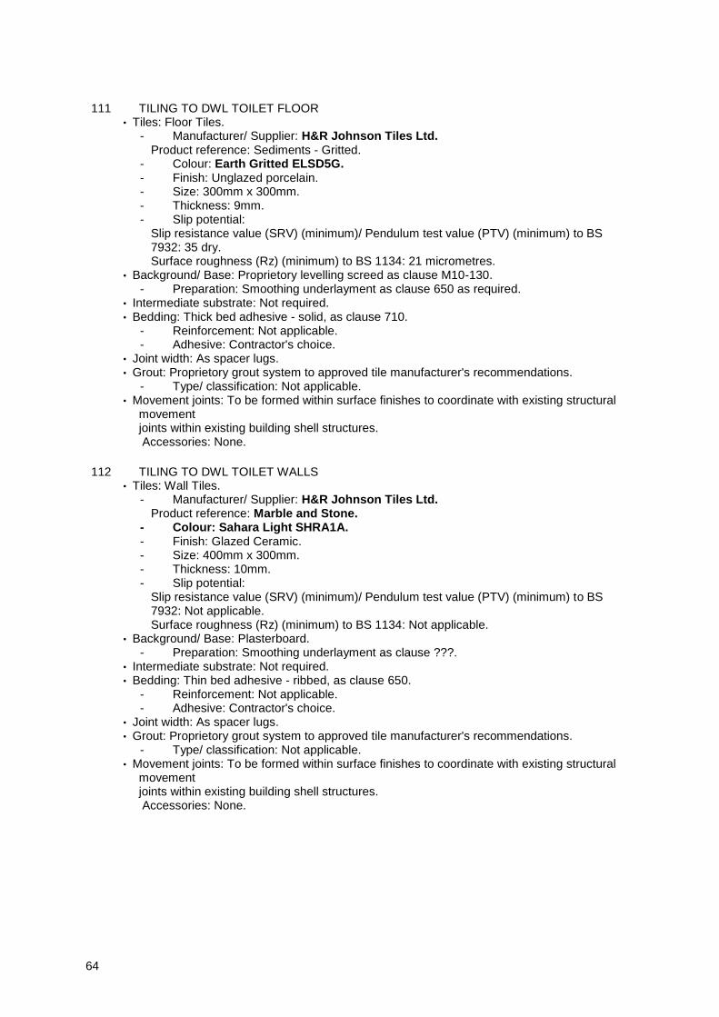
64
111 TILING TO DWL TOILET FLOOR • Tiles: Floor Tiles. - Manufacturer/ Supplier: H&R Johnson Tiles Ltd. Product reference: Sediments - Gritted. - Colour: Earth Gritted ELSD5G. - Finish: Unglazed porcelain. - Size: 300mm x 300mm. - Thickness: 9mm. - Slip potential: Slip resistance value (SRV) (minimum)/ Pendulum test value (PTV) (minimum) to BS 7932: 35 dry. Surface roughness (Rz) (minimum) to BS 1134: 21 micrometres. • Background/ Base: Proprietory levelling screed as clause M10-130. - Preparation: Smoothing underlayment as clause 650 as required. • Intermediate substrate: Not required. • Bedding: Thick bed adhesive - solid, as clause 710. - Reinforcement: Not applicable. - Adhesive: Contractor's choice. • Joint width: As spacer lugs. • Grout: Proprietory grout system to approved tile manufacturer's recommendations. - Type/ classification: Not applicable. • Movement joints: To be formed within surface finishes to coordinate with existing structural movement joints within existing building shell structures. Accessories: None.
112 TILING TO DWL TOILET WALLS • Tiles: Wall Tiles. - Manufacturer/ Supplier: H&R Johnson Tiles Ltd. Product reference: Marble and Stone. - Colour: Sahara Light SHRA1A. - Finish: Glazed Ceramic. - Size: 400mm x 300mm. - Thickness: 10mm. - Slip potential: Slip resistance value (SRV) (minimum)/ Pendulum test value (PTV) (minimum) to BS 7932: Not applicable. Surface roughness (Rz) (minimum) to BS 1134: Not applicable. • Background/ Base: Plasterboard. - Preparation: Smoothing underlayment as clause ???. • Intermediate substrate: Not required. • Bedding: Thin bed adhesive - ribbed, as clause 650. - Reinforcement: Not applicable. - Adhesive: Contractor's choice. • Joint width: As spacer lugs. • Grout: Proprietory grout system to approved tile manufacturer's recommendations. - Type/ classification: Not applicable. • Movement joints: To be formed within surface finishes to coordinate with existing structural movement joints within existing building shell structures. Accessories: None.
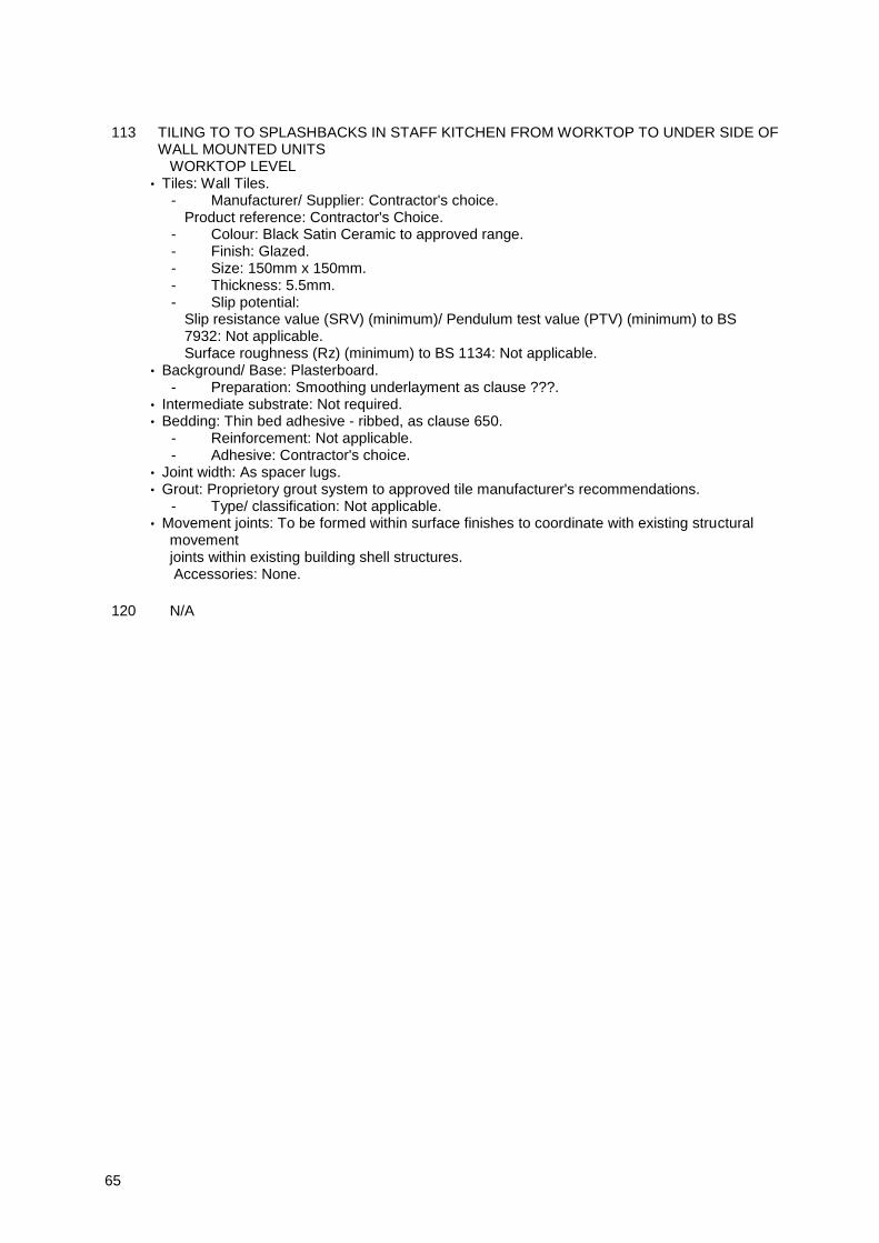
65
113 TILING TO TO SPLASHBACKS IN STAFF KITCHEN FROM WORKTOP TO UNDER SIDE OF WALL MOUNTED UNITS
WORKTOP LEVEL • Tiles: Wall Tiles. - Manufacturer/ Supplier: Contractor's choice. Product reference: Contractor's Choice. - Colour: Black Satin Ceramic to approved range. - Finish: Glazed. - Size: 150mm x 150mm. - Thickness: 5.5mm. - Slip potential: Slip resistance value (SRV) (minimum)/ Pendulum test value (PTV) (minimum) to BS 7932: Not applicable. Surface roughness (Rz) (minimum) to BS 1134: Not applicable. • Background/ Base: Plasterboard. - Preparation: Smoothing underlayment as clause ???. • Intermediate substrate: Not required. • Bedding: Thin bed adhesive - ribbed, as clause 650. - Reinforcement: Not applicable. - Adhesive: Contractor's choice. • Joint width: As spacer lugs. • Grout: Proprietory grout system to approved tile manufacturer's recommendations. - Type/ classification: Not applicable. • Movement joints: To be formed within surface finishes to coordinate with existing structural movement joints within existing building shell structures. Accessories: None.
120 N/A

66
GENERAL
210 SUITABILITY OF BACKGROUNDS/ BASES • Background/ base tolerances: To permit specified flatness/ regularity of finished surfaces given the permissible minimum and maximum thickness of bedding. • New background drying times (minimum): - Concrete walls: 6 weeks. - Brick/ block walls: 6 weeks. - Rendering: 2 weeks. - Gypsum plaster: 4 weeks. • New base drying times (minimum): - Concrete slabs: 6 weeks. Cement:sand screeds: 3 weeks.
215 FALLS IN THE BASES General: Give notice if falls are inadequate.
250 SAMPLES • General: Submit representative samples of the following: Each type of tile.
260 CONTROL SAMPLES • General: Complete sample areas, being part of finished work, in locations as follows: To be confirmed by Architect.
PREPARATION
310 EXISTING BACKGROUNDS/BASES GENERALLY • Efflorescence, laitance, dirt and other loose material: Remove. • Deposits of oil, grease and other materials incompatible with the bedding: Remove. • Tile, paint and other nonporous surfaces: Clean. Wet backgrounds: Dry before tiling.
320 EXISTING CONCRETE/SCREEDS • Loose or hollow portions: Cut out. Making good: Material recommended by tiling adhesive manufacturer.
355 OLD ADHESIVE RESIDUES ON CONCRETE/SCREED BASES Soft or unsound adhesive residues: Remove without damaging base.
360 EXISTING PAINT Paint with unsatisfactory adhesion: Remove so as not to impair bedding adhesion.
370 NEW IN SITU CONCRETE • Backrounds/ bases to be tiled: Remove mould oil, surface retarders and other materials incompatible with bedding.
380 NEW PLASTER • Plaster: Dry, solidly bedded, free from dust and friable matter. Plaster primer: Apply if recommended by adhesive manufacturer.
390 PLASTERBOARD BACKGROUNDS • Boards: Dry, securely fixed and rigid with no protruding fixings and face to receive decorative finish exposed.

67
400 BACKGROUNDSWOOD BASED BOARDS • Boards: Dry, securely fixed and rigid with no protruding fixings. Surfaces to be tiled: Seal or prime if recommended by adhesive manufacturer.
410 HACKING FOR KEY • Keying: Roughen backgrounds thoroughly and evenly to a depth of 3 mm. Backgrounds to be keyed: ALL EXISTING WALLS.
420 RAKING OUT FOR KEY Soft joints in existing masonry: Rake out to a depth of 13 mm (minimum).
431 STIPPLING FOR KEY • Stipple mix: - Cement: Portland to BS EN 197-1 type CEM I/42.5. - Sand: Clean coarse. - Proportions (cement:sand): 1-1.5:2. - Admixture: BBA certified SBR bonding agent. • Application/ finish: Brush applied to a deep close texture. Curing/ drying: Keep damp until hardened. Dry out to provide securely bonded finish.
438 PREPARING CONCRETE BASES FOR FULLY BONDED BEDDING • Surface cement:sand matrix: Remove to expose coarse aggregate. • Surface preparation: Suitable to achieve a full bond with bedding. Select from: - Keep well wetted for several hours. Remove free water then brush in a slurry bonding coat. Slurry: SBR polymer modified cement. - Prepare, prime as necessary and apply a bonding agent. Bonding agent: BBA certified SBR bonding agent.
460 SMOOTHING UNDERLAYMENT • Type: Recommended by adhesive manufacturer. Condition: Allow to dry before tiling.
FIXING
510 FIXING GENERALLY • Colour/shade: Unintended variations within tiles for use in each area/room are not permitted. - Variegated tiles: Mix thoroughly. • Adhesive: Compatible with background/base. Prime if recommended by adhesive manufacturer. • Cut tiles: Neat and accurate. • Fixing: Provide adhesion over entire background/base and tile backs. • Final appearance: Before bedding material sets, make adjustments necessary to give true, regular appearance to tiles and joints when viewed under final lighting conditions. Surplus bedding material: Clean from joints and face of tiles without disturbing tiles.

68
530 SETTING OUT • Joints: True to line, continuous and without steps. - Joints on walls: Horizontal, vertical and aligned round corners. - Joints in floors: Parallel to the main axis of the space or specified features. • Cut tiles: Minimize number, maximize size and locate unobtrusively. • Joints in adjoining floors and walls: Align. • Joints in adjoining floors and skirtings: Align. • Movement joints: Where locations are not indicated, submit proposals. • Setting out of Floor Tiles Generally : Drawing references: 20-401. Setting out of N/A : Submit proposals.
540 LEVEL OF FLOOR TILING Permissible deviation in level from datum 2mm.
550 FLATNESS/ REGULARITY OF TILING • Sudden irregularities: Not permitted. • Deviation of surface: Measure from underside of a 2 m straightedge placed anywhere on surface. The straightedge should not be obstructed by the tiles and no gap should be greater than 3 mm.
560 LEVEL OF TILING ACROSS JOINTS • Deviation (maximum) between tile surfaces either side of any type of joint: - 1 mm for joints less than 6 mm wide. 2 mm for joints 6 mm or greater in width.
600 SIT-ON TILE SKIRTINGS • Sequence: Bed solid to wall after laying floor tiles. Bedding: Cement based adhesive.
650 THIN BED ADHESIVE - RIBBED (WALLS) • Application: Apply 3 mm floated coat of adhesive to dry background in areas of approximately 1 m². Trowel to ribbed profile. Tiling: Press tiles firmly onto float coat.
660 THIN BED ADHESIVE - MESH BACKED MOSAIC (WALLS) • Application: Apply 3 mm floated coat of adhesive to dry background. Comb surface. • Placing mosaic sheets: Hang in horizontal rows, working downwards. Stagger vertical joints. Prevent slippage of sheets. Lightly beat mosaics into adhesive. Width, plane and alignment of joints between sheets: To match joints between mosaic
661 THIN BED ADHESIVE - PAPER FACED MOSAIC (WALLS) • Application: Apply 3 mm floated coat of adhesive to dry background. Comb surface. • Preparing mosaic sheets: Pre-grout. Remove surplus before fixing. • Placing mosaic sheets: Hang in horizontal rows, working downwards. Stagger vertical joints. • Width, plane and alignment of joints between sheets: To match joints between mosaic tiles. Paper face: Before adhesive hardens completely, remove paper face. Complete grouting.
710 THICK BED ADHESIVE - SOLID (FLOORS) • Application: Apply floated coat of adhesive to dry base and comb surface. • Tiling: Apply coat of adhesive to backs of tiles filling depressions or keys. Press tiles firmly into position. Finished adhesive thickness: Within range recommended by manufacturer.
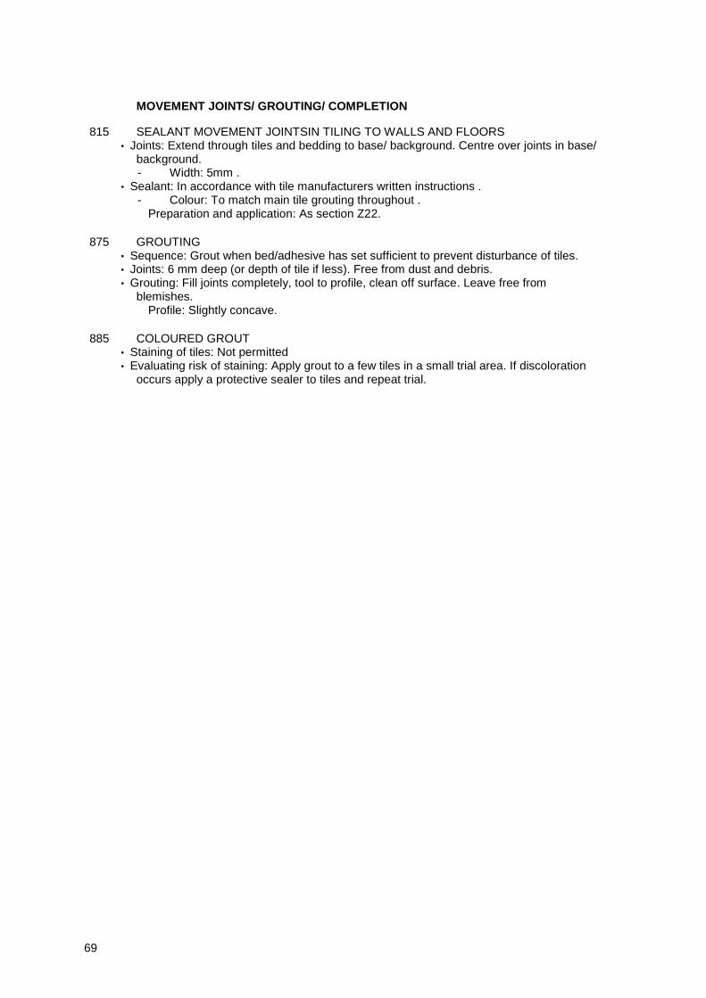
69
MOVEMENT JOINTS/ GROUTING/ COMPLETION
815 SEALANT MOVEMENT JOINTSIN TILING TO WALLS AND FLOORS • Joints: Extend through tiles and bedding to base/ background. Centre over joints in base/ background. - Width: 5mm . • Sealant: In accordance with tile manufacturers written instructions . - Colour: To match main tile grouting throughout . Preparation and application: As section Z22.
875 GROUTING • Sequence: Grout when bed/adhesive has set sufficient to prevent disturbance of tiles. • Joints: 6 mm deep (or depth of tile if less). Free from dust and debris. • Grouting: Fill joints completely, tool to profile, clean off surface. Leave free from blemishes. Profile: Slightly concave.
885 COLOURED GROUT • Staining of tiles: Not permitted • Evaluating risk of staining: Apply grout to a few tiles in a small trial area. If discoloration occurs apply a protective sealer to tiles and repeat trial.

70
M50
Rubber/ plastics/ cork/ lino/ carpet tiling/ sheeting
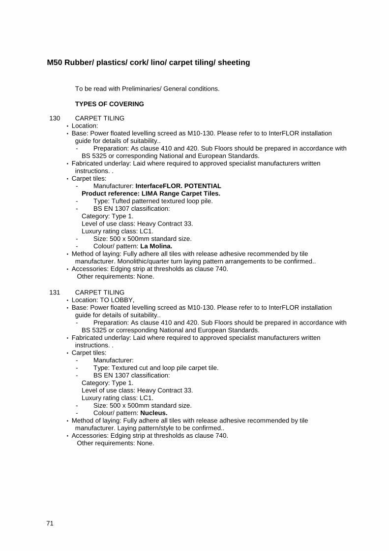
71
M50 Rubber/ plastics/ cork/ lino/ carpet tiling/ sheeting
To be read with Preliminaries/ General conditions.
TYPES OF COVERING
130 CARPET TILING • Location: • Base: Power floated levelling screed as M10-130. Please refer to to InterFLOR installation guide for details of suitability.. - Preparation: As clause 410 and 420. Sub Floors should be prepared in accordance with BS 5325 or corresponding National and European Standards. • Fabricated underlay: Laid where required to approved specialist manufacturers written instructions. . • Carpet tiles: - Manufacturer: InterfaceFLOR. POTENTIAL Product reference: LIMA Range Carpet Tiles. - Type: Tufted patterned textured loop pile. - BS EN 1307 classification: Category: Type 1. Level of use class: Heavy Contract 33. Luxury rating class: LC1. - Size: 500 x 500mm standard size. - Colour/ pattern: La Molina. • Method of laying: Fully adhere all tiles with release adhesive recommended by tile manufacturer. Monolithic/quarter turn laying pattern arrangements to be confirmed.. • Accessories: Edging strip at thresholds as clause 740. Other requirements: None.
131 CARPET TILING • Location: TO LOBBY, • Base: Power floated levelling screed as M10-130. Please refer to to InterFLOR installation guide for details of suitability.. - Preparation: As clause 410 and 420. Sub Floors should be prepared in accordance with BS 5325 or corresponding National and European Standards. • Fabricated underlay: Laid where required to approved specialist manufacturers written instructions. . • Carpet tiles: - Manufacturer: - Type: Textured cut and loop pile carpet tile. - BS EN 1307 classification: Category: Type 1. Level of use class: Heavy Contract 33. Luxury rating class: LC1. - Size: 500 x 500mm standard size. - Colour/ pattern: Nucleus. • Method of laying: Fully adhere all tiles with release adhesive recommended by tile manufacturer. Laying pattern/style to be confirmed.. • Accessories: Edging strip at thresholds as clause 740. Other requirements: None.

72
132 CARPET TILING • Location: • Base: Power floated levelling screed as M10-130. Please refer to to guide for details of suitability.. - Preparation: As clause 410 and 420. Sub Floors should be prepared in accordance with BS 5325 or corresponding National and European Standards. • Fabricated underlay: Laid where required to approved specialist manufacturers written instructions. . • Carpet tiles:. Product reference: Furrows II Range Carpet Tiles. - Type: Tufted patterned structured loop pile carpet tile, manufactured from recycled solution dyed nylon with Graphlex backing. - BS EN 1307 classification: Category: Type 1. Level of use class: Heavy Contract 33. Luxury rating class: LC1. - Size: 500 x 500mm standard size. - Colour/ pattern: 303432 Hemp. • Method of laying: Fully adhere all tiles with release adhesive recommended by tile manufacturer. Laying pattern/style Monolithic.. • Accessories: Edging strip at thresholds as clause 740. Other requirements: None.
150 SHEETING- LINOLEUM • Location: • Base: Power floated levelling screed as M10-130. Please refer to to Polyflor Ltd installation guide for details of suitability. - Preparation: As clause 410 and 420 and to approved specialist manufacturer's written instructions.. • Fabricated underlay: none. • Flooring roll: Homogeneous PVC to BS EN 649 laminated construction. - Manufacturer:. Product reference: - BS EN 685 class: 34. - Width: Flexible PVC plank flooring to approved specialist manufacturer's standard sizes. - Thickness: 3mm. - Colour/ pattern: Wood Pattern with colour ref.. • Adhesive (and primer if recommended by manufacturer): As clause 640. • Seam welding: Hot welding with complimentary coloured rod. • Accessories: Edging trim for perimeter of floor feature detail as clause 740. • Finishing: As clause 820. Other requirements: None.
73
151 SHEETING- LINOLEUM • Location: • Base: Power floated levelling screed as M10-130. Please refer to to Polyflor Ltd installation guide for details of suitability. - Preparation: As clause 410 and 420 and to approved specialist manufacturer's written instructions.. • Fabricated underlay: none. • Flooring roll: Homogeneous PVC to BS EN 649 laminated construction. - Manufacturer: . - BS EN 685 class: 34. - Width: Flexible PVC plank flooring to approved specialist manufacturer's standard sizes. - Thickness: 3mm. - Colour/ pattern:. • Adhesive (and primer if recommended by manufacturer): As clause 640. • Seam welding: Hot welding with complimentary coloured rod. • Accessories: Edging trim for perimeter of floor feature details, and thresholds as clause 740. • Finishing: As clause 820. Other requirements: None.
152 SHEETING- LINOLEUM • Location: TO STAFF KITCHEN. • Base: Power floated levelling screed as M10-130. - Preparation: As clause 410 and 420. • Fabricated underlay: none. • Flooring roll: Homogeneous PVC to BS EN 649. - Manufacturer: Armstrong Limited. Product reference: Safeguard. - BS EN 685 class: 34. - Width: 2000 mm. - Thickness: 2mm. - Colour/ pattern: 390080 Light Gray. • Adhesive (and primer if recommended by manufacturer): As clause 640. • Seam welding: Hot welding with complimentary coloured rod. • Accessories: Edging trim for perimeter of carpeted areas as clause 740. • Finishing: As clause 820. Other requirements: None.
153 SHEETING- LINOLEUM • Location: TO SECURE STORE, SAFETY DEPOSIT AND CLEANERS CUPBOARD. • Base: Power floated levelling screed as M10-130. - Preparation: As clause 410 and 420. • Fabricated underlay: none. • Flooring roll: Homogeneous PVC to BS EN 649. - Manufacturer: Armstrong Limited. Product reference: Safeguard. - BS EN 685 class: 34. - Width: 2000 mm. - Thickness: 2mm. - Colour/ pattern: 39082 Anthracite. • Adhesive (and primer if recommended by manufacturer): As clause 640. • Seam welding: Hot welding with complimentary coloured rod. • Accessories: Edging trim for perimeter of carpeted areas and thresholds as clause 740. • Finishing: As clause 820. Other requirements: None.

74
GENERAL REQUIREMENTS
210 WORKMANSHIP GENERALLY • Base condition after preparation: Rigid, dry, sound, smooth and free from grease, dirt and other contaminants. • Finished coverings: Accurately fitted, tightly jointed, securely bonded, smooth and free from air bubbles, rippling, adhesive marks and stains.
220 SAMPLES Covering samples: Before placing orders, submit representative sample of each type.
250 LAYOUT - ROLL MATERIALS Setting out of seams: Agree setting out for sheeting types M50/ 150,151,152 and 153 .
251 LAYOUT - SEAMS IN ROLL MATERIALS • Setting out: Minimise occurrences of seams and cross seams. Cross seams: Not permitted in following locations: Not applicable.
252 LAYOUT - PATTERNS Setting out: Agree setting out for covering types M50/ 151 and 152 .
270 EXTRA MATERIAL • Provision of extra material: At completion, hand to Employer extra material of each type of covering to extent of 5%.
330 COMMENCEMENT • Required condition of works prior to laying materials: - Building is weathertight and well dried out. - Wet trades have finished work. - Paintwork is finished and dry. - Conflicting overhead work is complete. - Floor service outlets, duct covers and other fixtures around which materials are to be cut are fixed. Notification: Submit not less than 48 hours before commencing laying.
340 CONDITIONING • Prior to laying: Condition materials by unpacking and separating in spaces where they are to be laid. Maintain resilient flooring rolls in an upright position. Unroll carpet and keep flat on a supporting surface. • Conditioning time and temperature (minimum): As recommended by manufacturer with time extended by a factor of two for materials stored or transported at a temperature of less than 10°C immediately prior to laying.
350 ENVIRONMENT • Temperature and humidity: Before, during and after laying, maintain approximately at levels which will prevail after building is occupied. Ventilation: Before during and after laying, maintain adequate provision.
PREPARING BASES
410 NEW BASES • Suitability of bases and conditions within any area: Commencement of laying of coverings will be taken as acceptance of suitability.
75
420 EXISTING BASES • Notification: Before commencing work, confirm that existing bases will, after preparation, be suitable to receive coverings. • Suitability of bases and conditions within any area: Commencement of laying of coverings will be taken as acceptance of suitability.
430 NEW WET LAID BASES • Base drying aids: Not used for at least four days prior to moisture content testing. • Base moisture content test: Carry out in accordance with BS 5325, Annexe A or BS 8203, Annexe A. - Locations for readings: In all corners, along edges, and at various points over area being tested. • Commencement of laying coverings: Not until all readings show 75% relative humidity or less.
440 SUBSTRATES TO RECEIVE THIN COVERINGS • Trowelled finishes: Uniform, smooth surface free from trowel marks and other blemishes. Abrade suitably to receive specified floor covering material.
LAYING COVERINGS
610 SETTING OUT TILES • Method: Set out from centre of area/ room, so that wherever possible: - Tiles along opposite edges are of equal size. Edge tiles are more than 50% of full tile width.
620 COLOUR CONSISTENCY Finished work in any one area/ room: Free from banding or patchiness.
640 ADHESIVE FIXING GENERALLY • Adhesive type: As specified, as recommended by covering/ underlay, manufacturer or as approved. • Primer: Type and usage as recommended by adhesive manufacturer. • Application: As necessary to achieve good bond. • Finished surface: Free from trowel ridges, high spots caused by particles on the substrate, and other irregularities.
650 SEAMS • Patterns: Matched. Joints: Tight without gaps.
670 BORDERS/ AND FEATURE STRIPS IN SHEET MATERIAL • Curl: Not acceptable. Corners: Mitre joints.
680 SEAM WELDING COVERINGS • Commencement: At least 24 hours after laying, or after adhesive has set. Joints: Neat, smooth, strongly bonded, flush with finished surface.
700 LOOSE LAID CARPET TILES • Areas of adhered tiles: Secure using double sided tape or peelable adhesive. • Joints: Butted. Perimeter joints: Accurately cut to match abutment and prevent movement.

76
720 DOORWAYS Joint location: On centre line of door leaf.
740 EDGINGS AND COVER STRIPS • Manufacturer: Contractor's choice . - Product reference: Contractor's choice . • Material/ finish: Brushed aluminium . • Fixing: Secure with edge of covering gripped. Use matching fasteners where exposed to view
780 TRAFFICKING AFTER LAYING • Covering types: All. Traffic free period: Until adhesive is set.
COMPLETION
820 FINISHINGLINOLEUM FLOORING • Cleaning operations: - Wash floor with water containing neutral (pH 6-9) detergent. If necessary, lightly scrub heavily soiled areas. - Rinse with clean water, removing surplus to prevent damage to adhesive. Allow to dry. Emulsion polish: Two coats of a type recommended by covering manufacturer.
880 WASTE • Spare covering material: Retain suitable material for patching. On completion submit pieces for selection. Hand over selected pieces to Employer.

77
M52
Decorative papers/ fabrics
78
M52 Decorative papers/ fabrics
To be read with Preliminaries/ General conditions.
TYPES OF COVERING
110 • Substrate: New sealed plaster. - Preparation: To approved specialist wallpaper manufacturer's written instructions. - Treatment: To approved specialist wallpaper manufacturer's written instructions. • Adhesive: Tekfix Plus as covering manufacturer's recommendations for substrate. • Lining: Commercial quality vinyl wallcovering laminated onto a polycotton scrim backing.. • Covering: Heavy duty decorative fabric backed wallpaper. - Manufacturer: - Roll width: Manufacturer's standard 1300 x 350mm. - Other requirements: Class 0 and 1 surface spread of flame to BS476 part 6 and 7 / Euroclass B / Marine..
GENERALLY
220 SAMPLES • General: Submit a representative sample of each type of covering before placing orders. Size (minimum): Roll width x A length to include pattern repeat.
225 MARKING • Requirement: In accordance with BS EN 266, wallcoverings must state the following on each roll: - Supplier. - Product description. - Pattern/ batch number. - Grade of colour fastness to light. - Means of application. Type of adhesive to be used.
230 EXTRA MATERIAL • General: Provide extra coverings in clearly identified complete rolls/ lengths as follows: All covering types: 5% extra. • Ordering: At same time as installed material. Hand over to Employer at completion or when otherwise agreed.
241 ENVIRONMENT • Conditions: During hanging and drying of linings/ coverings, maintain working area ambient temperature and humidity levels approximate to those proposed in service.
251 CONDITIONING • General: Unwrap coverings and allow to acclimatize in working area as follows: Covering type M52/110: 24 hours.
79
PREPARATION
310 PREPARATION GENERALLY • Preparation materials: Types recommended by their manufacturers and covering manufacturer for situation and substrate being prepared. • Substrates: Sufficiently dry in depth to suit covering to be hung. • Efflorescence salts: Remove. • Dirt, grease and oil: Remove. Give notice if contamination of substrates has occurred. • Substrate irregularities: Fill cracks, joints, holes and other depressions with stoppers/ fillers. Work well in and finish off flush with surface. Abrade to a smooth finish. Dust, particles and residues from abrasion: Remove.
330 FIXTURES AND FITTINGS • Before commencing work: Remove the following: Coverplates, grilles, wall lights and other surface mounted fixtures. On completion of work: Clean and refix when coverings are dry.
340 COATED SUBSTRATES • Removing coatings: Do not damage substrate and adjacent surfaces or adversely affect subsequent coverings. • Loose, flaking or otherwise defective areas: Carefully remove to a firm edge. • Water soluble coatings: Completely remove. • Significant rot, corrosion or other degradation of substrates: If revealed, give notice. • Retained coatings: - Thoroughly clean to remove dirt, grease and contaminants. - Lead based coatings: If discovered, give notice. - Abrade gloss coated substrates to provide a key. Carry out tests for compatibility with adhesives.
370 ORGANIC GROWTHS • Loose growths and infected coatings/ decorations: Remove and dispose of. • Treatment biocide: Apply appropriate solution to growth areas and surrounding surfaces. • Dead growth: Remove and dispose of. • Residual effect biocide: Apply appropriate solution to inhibit re-establishment of growths. • Biocides: Types listed in current Health and Safety Executive (HSE) 'Pesticides', Part B, as surface biocides.
380 SIZE/ SEALER • Absorbent substrates: Apply one coat of a dilute solution of adhesive where recommended by covering manufacturer.
HANGING
420 HANGING GENERALLY • Coatings on adjacent surfaces: - Complete and dry before commencement of hanging coverings. - Efflorescene salts: Ensure no recurrence. • Sequence of hanging coverings: - Apply to ceilings before walls. - Commence adjacent to main source of natural light. - From centre of feature and isolated walls. • Surplus adhesive: Carefully remove from face of coverings, adjacent surfaces and fittings whilst still wet. • Completed coverings: Securely adhered, smooth and free of air bubbles, wrinkles, gaps, tears, adhesive marks and stains. Joints truly vertical/ horizontal and straight.
80
450 SETTING OUT • Approval of setting out: Obtain before commencement of hanging coverings, for the following: Covering type M52/110.
480 LININGS • Type and weight: To suit coverings and substrates. • Hang lengths: With neat butt joints; do not overlap. Drying period: Leave for 24 hours before hanging coverings.
490 COVERINGS • Selvedged coverings: Trim to a true straight edge before hanging, unless overlap joints are recommended by manufacturer. • Hanging lengths: - Wall coverings: Vertical. Ceiling coverings: Parallel to main window wall.
500 JOINTS IN COVERINGS • Butt joints: Hang lengths with neat butt joints generally. • Overlap joints: Hang lengths with neat overlap joints only where recommended by covering manufacturer. Cut through joints when stable to a true straight edge, without damaging substrate, and bond joints. • Cross joints: Hang lengths in one piece generally. Cross joints are only permitted where single lengths are impractical.
520 SHADING • Matching: Ensure colour consistency of adjacent lengths. • Hanging lengths: Use in sequence as cut from roll. • Alternate lengths: Do not reverse unless recommended by covering manufacturer. • Shade variation: Check after hanging first three lengths. If variation occurs, give notice before proceeding.
530 PATTERN • Patterned coverings: Accurately align and match. Mismatches: Anticipate and obtain approval for locations.

81
M60
Painting/clear finishing

82
M60 Painting/clear finishing
To be read with Preliminaries/General conditions.
COATING SYSTEMS
110 EMULSION PAINTTO INTERNAL PLASTERED SURFACES • Manufacturer: As finishes schedule. - Product reference: As finishes schedule. • Surfaces: Internal. - Preparation: As clause 400 . • Initial coats: As recommended by manufacturer . • - Number of coats: As recommended by manufacturer . • Undercoats: As recommended by manufacturer . - Number of coats: As recommended by manufacturer . • Finishing coats: As finishes schedule . Number of coats: 2 or as recommended by manufacturer .
130 GLOSS PAINTTO INTERNAL EXPOSED SOFTWOOD • Manufacturer: As finishes schedule . - Product reference: As finishes schedule . • Surfaces: Preprimed and sealed . - Preparation: As clause 400 . • Initial coats: As recommended by manufacturer . - Number of coats: As recommended by manufacturer . • Undercoats: As recommended by manufacturer . - Number of coats: As recommended by manufacturer . • Finishing coats: Full gloss . Number of coats: 2 or as recommended by manufacturer .
150 SATINWOOD PAINT TO INTERNAL PLASTERED SURFACES AND EXPOSED SOFTWOOD . • Manufacturer: As finishes schedule . - Product reference: As finishes schedule . • Surfaces: Preprimed and sealed . - Preparation: As clause 400 . • Initial coats: As recommended by manufacturer . - Number of coats: As recommended by manufacturer . • Undercoats: As recommended by manufacturer . - Number of coats: As recommended by manufacturer . • Finishing coats: Eggshell / Satin . Number of coats: 2 or as recommended by manufacturer .
160 DECORATIVE WOODSTAIN/ VARNISH/ PRESERVATIVETO INTERNAL HARDWOOD FINISHES GENERALLY • Manufacturer: As finishes schedule . - Product reference: As finishes schedule . • Surfaces: Internal . - Preparation: As clause 400 . • Initial coats: As recommended by manufacturer . - Number of coats: As recommended by manufacturer . • Finishing coats: As recommended by manufacturer . Number of coats: As recommended by manufacturer .

83
GENERALLY
210 COATING MATERIALS • Manufacturers: Obtain materials from any of the following: As finishes schedule. Selected manufacturers: Submit names before commencement of coating work.
215 HANDLING AND STORAGE • Coating materials: Deliver in sealed containers, labelled clearly with brand name, type of material and manufacturer's batch number. • Materials from more than one batch: Store separately. Allocate to distinct parts or areas of the work.
220 COMPATIBILITY • Coating materials selected by contractor: - Recommended by their manufacturers for the particular surface and conditions of exposure. - Compatible with each other. - Compatible with and not inhibiting performance of preservative/fire retardant pretreatments.
240 SURFACES NOT TO BE COATED Radiator valves and stop valves.
280 PROTECTION • 'Wet paint' signs and barriers: Provide where necessary to protect other operatives and general public, and to prevent damage to freshly applied coatings.
320 INSPECTION BY COATING MANUFACTURERS • General: Permit manufacturers to inspect work in progress and take samples of their materials from site if requested.
PREPARATION
400 PREPARATION GENERALLY • Standard: In accordance with BS 6150. • Suspected existing hazardous materials: Prepare risk assessments and method statements covering operations, disposal of waste, containment and reoccupation, and obtain approval before commencing work. • Preparation materials: Types recommended by their manufacturers and the coating manufacturer for the situation and surfaces being prepared. • Substrates: Sufficiently dry in depth to suit coating. • Efflorescence salts: Remove. • Dirt, grease and oil: Remove. Give notice if contamination of surfaces/ substrates has occurred. • Surface irregularities: Remove. • Joints, cracks, holes and other depressions: Fill flush with surface, to provide smooth finish. • Dust, particles and residues from preparation: Remove and dispose of safely. • Water based stoppers and fillers: - Apply before priming unless recommended otherwise by manufacturer. - If applied after priming: Patch prime. • Oil based stoppers and fillers: Apply after priming. • Doors, opening windows and other moving parts: - Ease, if necessary, before coating. Prime resulting bare areas.

84
420 FIXTURES AND FITTINGS • Removal: Before commencing work remove: Coverplates, grilles, wall clocks, and other surface mounted fixtures. Replacement: Refurbish as necessary, refit when coating is dry.
425 IRONMONGERY • Removal: Before commencing work: Remove ironmongery from surfaces to be coated. • Hinges: Do not remove. Replacement: Refurbishment as necessary; refit when coating is dry.
471 PREPRIMED WOOD Areas of defective primer: Take back to bare wood and reprime.
481 UNCOATED WOOD • General: Provide smooth, even finish with arrises and moulding edges lightly rounded or eased. • Heads of fasteners: Countersink sufficient to hold stoppers/fillers. Resinous areas and knots: Apply two coats of knotting.
590 UNCOATED PLASTERBOARD Depressions around fixings: Fill with stoppers/ fillers
601 UNCOATED PLASTERBOARD - TO RECEIVE TEXTURED COATING • Joints: Fill, tape and feather out with materials recommended by textured coating manufacturer.
622 ORGANIC GROWTHS • Dead and loose growths and infected coatings: Scrape off and remove from site. • Treatment biocide: Apply appropriate solution to growth areas and surrounding surfaces. Residual effect biocide: Apply appropriate solution to inhibit re-establishment of growths.
645 SEALING OF INTERNAL MOVEMENT JOINTS • General: To junctions of walls and ceilings with architraves, skirtings and other trims. • Sealant: Water based acrylic. - Manufacturer: Contractors choice. Product reference: Contractors choice. Preparation and application: As section Z22.
APPLICATION
711 COATING GENERALLY • Application standard: In accordance with BS 6150, clause 9. • Conditions: Maintain suitable temperature, humidity and air quality during application and drying. • Surfaces: Clean and dry at time of application. • Thinning and intermixing of coatings: Not permitted unless recommended by manufacturer. • Overpainting: Do not paint over intumescent strips or silicone mastics. • Priming coats: - Thickness: To suit surface porosity. - Application: As soon as possible on same day as preparation is completed. • Finish: - Even, smooth and of uniform colour. - Free from brush marks, sags, runs and other defects. Cut in neatly.

85
720 PRIMING JOINERY • Preservative treated timber: Retreat cut surfaces with two flood coats of a suitable preservative before priming. End grain: Coat liberally allow to soak in, and recoat.
751 STAINING WOOD • Primer: Apply if recommended by stain manufacturer. • Application: Apply in flowing coats and brush out excess stain to produce uniform appearance.
760 VARNISHING WOOD • First coat: Thin with plant oil based thinner. - Brush well in and lay off avoiding aeration. Subsequent coats: Rub down lightly along the grain between coats.
800 GLAZING • Etched, sand blasted and ground glass: Treat or mask edges before coating to protect from contamination by oily constituents of coating materials.

86
N
Furniture/Equipment

87
N10
General fixtures/ furnishings/ equipment
88
N10 General fixtures/ furnishings/ equipment
To be read with Preliminaries/General conditions.
PRODUCTS
110 • Manufacturer:. • Performance: • Dimensions: To approved specialist manufacturer's drawings. • Timber: To BS EN 942. - Species: To approved specialist manufacturer's drawings. - Appearance class: J2. - Moisture content on delivery: 9 to 13%. • Wood based boards: To approved specialist manufacturer's drawings. • Metal: To approved specialist manufacturer's drawings. - Grade: To approved specialist manufacturer's drawings. • Other materials: To approved specialist manufacturer's drawings. • Finishes: To approved specialist manufacturer's drawings. • Adhesive: To approved specialist manufacturer's drawings. • Fixings: To approved specialist manufacturer's drawings. - Fasteners: To approved specialist manufacturer's drawings. • Joinery workmanship: As section Z10. • Metalwork materials and workmanship: As section Z11. Other requirements: To approved specialist manufacturer's drawings.
115 OFFICE TABLES AND DESKS • Item: TABLES/DESKS TO INTERVIEW ROOMS. • Manufacturer: - Product reference: • Supports: Legs and Panels. - Material: Moulded High Density Polyurethane. - Finish/ Colour: Laquered finish colour:. - Edges: Not required. • Pedestal units: - Material: N/A. - Finish/ Colour: N/A. - Edges: N/A. • Worktops: • Material: N/A. - Finish/ Colour: N/A. - Exposed edges: N/A. • Cable management: To BS 6396. • Integral screens: None. • Adjustability: To approved specialist manufacturer's standard design criterior. Other requirements: Cable tray.

89
116 STAFF KITCHEN TABLES • Item: TABLES TO STAFF KITCHEN. • Manufacturer: Orangebox Limited. - Product reference: Platto 08S. • Supports: Legs. - Material: Chromed Finished Steel. - Finish/ Colour: N/A. - Edges: Not required. • Pedestal units: - Material: N/A. - Finish/ Colour: N/A. - Edges: N/A. • Worktops: • Material: Plastics laminate faced 25mm MDF. - Finish/ Colour: White. - Exposed edges: To approved specialist manufacturer's standard unit specification . • Cable management: None. • Integral screens: None. • Adjustability: None. Other requirements: None.
117 WAITING AREA TABLES • Item: TABLES TO WAITING AREA. • Manufacturer: Orangebox Limited. - Product reference: Surf 10 (450mm high). • Supports: Legs. - Material: Turned Aluminium Polished Finish. - Finish/ Colour: Polished Finish. - Edges: Not required. • Pedestal units: - Material: N/A. - Finish/ Colour: N/A. - Edges: N/A. • Worktops: • Material: Glass top 10mm clear toughened to BS 6206. - Finish/ Colour: Glass. - Exposed edges: Polished radius edge detailing to approved specialist manufacturer's standard unit specification . • Cable management: None. • Integral screens: None. • Adjustability: None. Other requirements: None.

90
118 • Item:. • Manufacturer: - Product reference: • Supports: All to approved specialist manufacturer's standard unit specification. - Material: All to approved specialist manufacturer's standard unit specification. - Finish/ Colour:– - Edges: All to approved specialist manufacturer's standard unit specification. • Pedestal units: - Material: N/A. - Finish/ Colour: N/A. - Edges: N/A. • Worktops: • Material: N/A. - Finish/ Colour: N/A. - Exposed edges: N/A. • Cable management: To BS 6396. • Integral screens: None. • Adjustability: To approved specialist manufacturer's standard design criterior. Other requirements: Cable tray.
135 STORAGE AND DISPLAY UNITS • Item: TO MANAGERS SALES OFFICE AND INTERVIEW ROOMS. • Manufacturer: EFG Matthews Furniture Limited. - Product reference: Front Office Filing Storage Unit. • Dimensions: To approved manufacturer's standard unit size to be confirmed. • Test level to BS 5459-3: To approved manufacturer's standard unit specification. • Doors/ Drawers: - Material: Fully Welded Steel Carcass. - Finish/ Colour: Black. • Outer panels/ Plinths/ Shelves: - Material: Sheet steel powder coated. - Finish/ Colour: Powdercoated. • Frames/ Legs: - Material: N/A. - Finish/ Colour: N/A. Other requirements: N/A.
165 OFFICE SHELVING SYSTEM TO BACK OF HOUSE AREAS • Standard: To BS 5459-3. • Manufacturer: To be confirmed, Contractor Supplied to client brief. - Product reference: To be confirmed, Contractor Supplied to client brief. • Test level: To BS 5459-3: To client's brief. • Shelves: - Material: To be confirmed, Contractor Supplied to client brief. - Finish/ Colour: To be confirmed, Contractor Supplied to client brief. • Other components: - Back panels; - End panels; and - Support brackets.
170 • Manufacturer:. - Product reference:. • Material: Fully microfibre fabric upholstered finish to unit. • Finish/ Colour: Upholstery colours to be confirmed. Fittings: None.

91
177 CHAIRS TO INTERVIEW ROOMS AND WELCOME DESK • Standard: To BS EN 1335-2 and BS EN 15373. • Manufacturer: Orangebox Limited. - Product reference: Task Seating G464. • Size: To BS EN 1335-1. • Adjustability: Heights of seat and armrests and Rake of chair back. • Seat/ Back/ Arms: - Material: Standard Back shell, aluminium base, brushed chrome gas lift, two tone upholstered finish to seat. - Finish/ Colour: Upholstery colours to be confirmed. • Frame: - Material: Tubular metal. - Finish/ Colour: Aluminium base and columns. • Other requirements: Casters colour RAL 9006 light grey Base section powdercoated RAL 813.
177A CHAIRS TO BACK OFFICE AND SAFETY DEPOSIT • Standard: To BS EN 1335-2 and BS EN 15373. • Manufacturer: Orangebox Limited. - Product reference: Task Seating G464. • Size: To BS EN 1335-1. • Adjustability: Heights of seat and armrests and Rake of chair back. • Seat/ Back/ Arms: - Material: Standard Back shell, aluminium base, brushed chrome gas lift, two tone upholstered finish to seat. - Finish/ Colour: Upholstery colours to be confirmed. • Frame: - Material: Tubular metal. - Finish/ Colour: Aluminium base and columns. • Other requirements: Casters colour RAL 9006 light grey Base section powdercoated RAL 813.
178 CHAIRS TO WAITING AREAS • Standard: To BS EN 1335-2 and BS EN 15373. • Manufacturer:. - . • Size: To BS EN 1335-1. • Adjustability: None. • Seat/ Back/ Arms: - Material: Fully microfibre fabric upholstered finish to unit. - Finish/ Colour: Upholstery colours to be confirmed. • Frame: - Material: To approved manufacturer's standard specification. - Finish/ Colour: To approved manufacturer's standard specification. Other requirements: None.
92
179 CHAIRS TO CASHIERS • Standard: To BS EN 1335-2 and BS EN 15373. • Manufacturer: Orangebox Limited. - Product reference: Task Seating GO CCA Swivel Counter Armchair . • Size: To BS EN 1335-1-3 / BS EN ISO 9241 5 year warranty. • Adjustability: Heights of seat and armrests and Rake of chair back. • Seat/ Back/ Arms: - Material: Standard Back shell fully upholstered, aluminium base, Stroke 115mm gas lift in brushed steel, two tone upholstered finish to seat. Moulded CMHR Foam. Vertically adjustable arms in nylon.. - Finish/ Colour: Upholstery colours to be confirmed. • Frame: - Material: Chrome Tubular metal. - Finish/ Colour: Aluminium base and columns in chrome. • Other requirements: Casters colour RAL 9006 light grey Base section powdercoated RAL to be confirmed. Extra height lift and footring.
179A CHAIRS TO STAFF KITCHEN • Standard: To BS EN 1335-2 and BS EN 15373. • Manufacturer: Orangebox Limited. - Product reference: Poro. • Size: To BS EN 1335-1-3 / BS EN ISO 9241 5 year warranty. • Adjustability: None. • Seat/ Back/ Arms: - Material: Coloured beech finished seat and back. Tubular steel frame.. - Finish/ Colour: Seat and back colours to be confirmed. • Frame: - Material: Tubular steel. - Finish/ Colour: Chrome finish. Other requirements: None.
193 WHITEBOARDS TO KITCHEN AND BACK OFFICE • Type: Marker pen. • Manufacturer: Contractor's choice. - Product reference: Contractor's choice. • Frame: - Material: Brushed aluminium. - Finish/ Colour: Brushed aluminium. • Surface: - To BS EN 438-1 - Markings: None. - Colour: White. • Size: 1800mm wide x 1200mm deep. Accessories: 300mm clip on pen ledge.
270 MIRRORS TO DWL TOILETS Ref: NBS L40-550 • Material: Class C safety glass to BS 6206 . • Quality: Free from tarnishing, discoloration, scratches and other defects visible in the designed viewing conditions. Reflection undistorted. • Size: TBC. • Backing: Aluminium foil. • Edges: Polished Bevel. • Fixing: CP dome top wood screws with polyethylene sleeves and washers. Installation: Accurately with sides vertical.

93
290 MATWELL FRAMES TO FRONT ENTRANCE • Manufacturer: Gradus Esplanade // Bonar Floors Limited. - Product reference: To suit entrance matting system clause 300. • Material: Aluminium. - Finish: Brushed aluminium finish. • Size: 2000mm x 2000mm. • Angles: 50 x 50 x 5 mm thick. - Corners: Mitred and welded. - Angle size: To suit approved mat thickness and to approved manufacturer's recommendations.
300 ENTRANCE MATTING TO FRONT ENTRANCE • Manufacturer: GRADUS // Bonar Floors Limited . - Product reference: Tessera Coral Duo . • Colour: 9101 . Size: 2000mm x 2000mm to suit internal matwell frame size installed .
350 MISCELLANEOUS FITTINGS • Item: 5 No. Artificial Bamboo Plants and pot /stands. • Manufacturer: To be confirmed . - Product reference: To be confirmed. • Size/ Capacity: 1500mm high. • Finish/ Colour: To be confirmed. • Fixing: Free standing. Other requirements: None.
460 SEALANTTO WORKTOPS AND VANITY FURNITURE • Standard: To BS EN ISO 11600, class F20 HM. • Type: One part silicone. - Manufacturer: Contractor's choice. - Product reference: Contractor's choice. Colour: To match surrounding furniture and finishes colours to be confirmed.
EXECUTION
710 MOISTURE CONTENT OF WOOD AND WOOD BASED BOARDS • Temperature and humidity: During delivery, storage, fixing and to handover maintain conditions to suit specified moisture contents of timber components. • Testing: When instructed, test components with approved moisture meter to manufacturer's recommendations.
720 INSTALLATION GENERALLY • General: As Preliminaries section A33. • Fixing and fasteners: As section Z20. Services: As Engineering Services specification.
760 SEALANT BEDDING AND POINTING • Application: As section Z22. • Bedding: Sink to top of worktops and splashbacks, sanitary fittings and furniture. Pointing: Between units and splash backs, sanitary fittings and furniture.
770 TRIMS • Lengths: Wherever possible, unjointed between angles or ends of runs. • Running joints: Where unavoidable, obtain approval of location and method of jointing. Angle joints: Mitred.

94
COMPLETION
910 GENERAL • Doors and drawers: Accurately aligned, not binding. Adjusted to ensure smooth operation. Ironmongery: Checked, adjusted and lubricated to ensure correct functioning.
920 APPLIANCES • Test: Ensure that all functions and features work correctly. Documentation: Submit guarantees, instruction manuals, etc.

95
N11
Domestic kitchen fittings, furnishings and equipment

96
N11 Domestic kitchen fittings, furnishings and equipment
To be read with Preliminaries/ General conditions.
PRODUCTS
310 FITTED BASE UNITS TO STAFF KITCHEN • Standard: To BS 6222 -2 and -3, and BS EN 14749. • Manufacturer: ADOVE AVERAGE 18mm - Product reference: Contemporary Range - High Gloss WHITE. • Structural performance: To BS 6222-2, grade H. • Dimensions: To BS EN 1116. • Surface finishes: To BS 6222-3. • Doors and drawer fronts: - Material: High Gloss WHITE . - Finish and colour: High Gloss WHITE. - Edges: Plastics strip. - Other requirements: Concealed door hinges. • Side panels, plinths and shelves: - Material: High Gloss WHITE - Finish and colour: High Gloss WHITE - Edges: Plastics strip. Accessories: Legs and high gloss WHITE plinths, nickel effect bar handles,.
320 FITTED WALL UNITS TO STAFF KITCHEN • Standard: To BS 6222 -2 and -3, and BS EN 14749. • Manufacturer: ABOVE AVERAGE 18mm - Product reference: Contemporary Range - High Gloss WHITE. • Structural performance: To BS 6222-2, grade H. • Dimensions: To BS EN 1116. • Surface finishes: To BS 6222-3. • Doors and drawer fronts: - Material: High Gloss WHITE - Finish and colour: High Gloss WHITE - Edges: Plastics strip. - Other requirements: Concealed door hinges. • Side panels and shelves: - Material: High Gloss WHITE. - Finish and colour: High Gloss WHITE - Edges: Plastics strip. Accessories: Add on cornice and pelmet mouldings, nickel effect bar handles.
340 WORKTOPS TO STAFF KITCHEN • Standard: To BS 6222-3. • Manufacturer: ABOVE AVERAGE - Product reference: Contemporary Range Solid Wood 40mm Oak Block Worktop ref: WOH0980. • Material: Solid wood - Oak. • Dimensions: Refer to Architects Drawings. • Exposed edges: Solid wood. • Support: Supported on base units. Other requirements: Sealant to junction with internal walls.

97
341 WORKTOPS TO SAFETY DEPOSIT • Standard: To BS 6222-3. • Manufacturer: To be confirmed. - Product reference: To be confirmed. • Material: Laminate covered particle board type. • Dimensions: Refer to Architects Drawings. • Exposed edges: Laminate type 2. • Support: Individual stainless steel leg posts and frame. Other requirements: Sealant to junction with internal walls.
350 SINKS, TAPS, TRAPS AND WASTES TO STAFF KITCHEN • Sinks: - Standard: To BS EN 13310. - Manufacturer: To be confirmed. Product reference: To be confirmed. - Configuration: Single sink with left hand drainer. - Overall size: 1000 x 600. - Material: Stainless steel . Colour and finish: Stainless steel. • Tap/ chainstay/ overflow holes: - One tap hole, centre.; - No chainstay hole. ; and - Overflow hole.. • Taps: Mixer. - Manufacturer: To be confirmed. Product reference: To be confirmed. - Operation: Hand Wheel Type To be confirmed. - Material: Chromed steel. • Wastes: Plug and chain. - Standard: To BS EN 274-1, -2 and -3. - Manufacturer: To be confirmed. Product reference: To be confirmed. - Size: To fit sink . - Material: Chromed steel. - Tail: Slotted. • Traps: Tubular, P type. - Standard: To BS EN 274-1, -2 and -3. - Manufacturer: To be confirmed. Product reference: To be confirmed. - Size: To fit waste. - Material: Plastic. - Depth of seal (minimum): 75 mm. Accessories: Support brackets.
390 SEALANT • Standard: To BS EN ISO 11600, class F20 HM. • Type: One part silicone. - Manufacturer: Contractor's choice. Product reference: Contractor's choice. Colour: To match surrounding unit/worktop and finishes colours to be approved.
EXECUTION
610 MOISTURE CONTENT OF WOOD AND WOOD BASED BOARDS • Control and monitoring: Method statement: Submit.

98
620 INSTALLATION GENERALLY • Fixings and adhesives: As section Z20. Services: As Engineering Services specification.
630 INSTALLING UNITS AND WORKTOPS General: Well fitting, stable and secure.
640 INSTALLING APPLIANCES Connections: Provide to electric, gas, and hot and cold water services.
650 INSTALLING SINKS, TAPS AND WASTES • Water supply: To BS 6700 and BS EN 806-2. • Taps: - Fixing: Secure, watertight seal with the appliance. - Positioning: Hot tap to left of cold tap as viewed by the user of the appliance. • Wastes: - Bedding: Waterproof jointing compound. Fixing: With resilient washer between appliance and backnut.
660 SEALANT BEDDING AND POINTING • Application: As section Z22. • Bedding: Sink to top of worktop and splashbacks and floors. Pointing: Between units and splash backs and floors.
670 INSTALLING TRIMS AND MOULDINGS • Lengths: Un-jointed between angles or ends of runs. Angle joints: Mitred.
COMPLETION
910 GENERAL • Doors and drawers: Accurately aligned, not binding. Adjusted to ensure smooth operation. Ironmongery: Checked, adjusted and lubricated to ensure correct functioning.
920 APPLIANCE COMMISSIONING • Appliance operation, functions and controls: Verify. Documentation: Submit guarantees, instruction manuals, etc.

99
N13
Sanitary appliances and fittings

100
N13 Sanitary appliances and fittings
To be read with Preliminaries/ General conditions.
PRODUCTS
300 WCS AND CISTERNSCOMPLETE DOC M PACK TO DWL TOILET • WC standard: To DEFRA WC suite performance specification or equivalent approved by relevant water company. • Type: Wall hung, concealed cistern. • Pan: - Standards: To BS EN 33 and BS EN 997. - Manufacturer: Healey and Lord Limited. Product reference: HL Premium Wall Hung Doc M Pack With Auto Tap & No Touch Flush Sensor, Professional Doc M pack. - Material: Vitreous china, white. • Seat and cover: - Standard: To BS 1254, ring seat. - Manufacturer: As Pan. Product reference: As approved HL Professional Doc M pack. - Material: As approved HL Professional Doc M pack. • Pan connector: - Standard: To BS 5627. - Manufacturer: As Pan. Product reference: As approved HL Professional Doc M pack. - Colour: White. • Cistern: - Standard: To BS 7357. - Manufacturer: As Pan. Product reference: As approved HL Professional Doc M pack. - Material: Vitreous china. - Colour and finish: To match pan. • Flushing arrangement: Plastics diaphragm type float operated valve and siphon, to BS 1212-3 and float to BS 2456. - Manufacturer: As Pan. Product reference: As approved HL Professional Doc M pack. - Operating control: Push button with wall rose fitting, brushed stainless steel finish. - Water supply connection: Side. - Flush volume: 6 L. • Flush pipe: Not required. - Manufacturer: Not applicable. Product reference: Not applicable. - Material: Not applicable. • Accessories: Infra Red Disabled Toilet mixer tap chrome finished, Brushed stainless steel paper towel dispenser and manual soap dispenser, all supplied by Healey and Lord Ltd. Concealed support frames, Overflow standpipe and connector.
311 DOCUMENT M PACKAGESTO DWL TOILET • Manufacturer: As approved stainless steel complete Doc M Pack. - Product reference: As approved stainless steel complete Doc M Pack. Type approval certificate: Submit.

101
472 WARM AIR HAND DRIERSTO DWL TOILET - YES • Manufacturer: Dart Valley Systems Limited. - Product reference: 2.2kw Hand Dryer D146/PC Polished Chrome . Electrical supply: Fused switched 13A connection unit.
580 SEALANT FOR POINTING • Standard: To BS EN ISO 11600. - Class: F20 HM. • Type: One part silicone. - Manufacturer: Contractor's choice. - Product reference: Contractor's choice. Colour: clear.
EXECUTION
610 INSTALLATION GENERALLY • Assembly and fixing: Surfaces designed to falls to drain as intended. • Fasteners: Nonferrous or stainless steel. • Supply and discharge pipework: Fix before appliances. • Fixing: Fix appliances securely to structure. Do not support on pipework. • Jointing and bedding compounds: Recommended by manufacturers of appliances, accessories and pipes being jointed or bedded. • Appliances: Do not use. Do not stand on appliances. • On completion: Components and accessories working correctly with no leaks. Labels and stickers: Remove.
613 COMPATIBILITY OF COMPONENTS • General: Each sanitary assembly must consist of functionally compatible components, preferably obtained from a single manufacturer. Exceptions: Water supply fittings, wastes and traps.
620 NOGGINGS AND BEARERS • Noggings, bearers, etc. to support sanitary appliances and fittings: Position accurately. Fix securely.
630 TILED BACKGROUNDS OTHER THAN SPLASHBACKS • Timing: Complete before fixing appliances. Fixing appliances: Do not overstress tiles.
650 INSTALLING WC PANS • Floor mounted pans: Screw fix and fit cover caps over screw heads. Do not use mortar or other beddings. Seat and cover: Stable when raised.
670 INSTALLING CISTERNS • Cistern operating components: Obtain from cistern manufacturer. - Float operated valve: Matched to pressure of water supply. • Overflow pipe: Fixed to falls and located to give visible warning of discharge. Location: Agreed, where not shown on drawings.
710 INSTALLING TAPS • Fixing: Secure against twisting. • Seal with appliance: Watertight. Positioning: Hot tap to left of cold tap as viewed by user of appliance.

102
720 INSTALLING WASTES AND OVERFLOWS • Bedding: Waterproof jointing compound. Fixing: With resilient washer between appliance and backnut.
755 SEALANT BEDDING AND POINTING • Bedding: Bed sinks to top and sides fixed to tiled walls. . Pointing: Joints between appliances and walls, floors. .

103
N14
General signage systems
104
N14 General signage systems
To be read with Preliminaries/ General conditions.
GENERAL
110 SIGNAGE SYSTEM INTERNALLY TO BANKING HALL AND SALES AREAS • System manufacturer: To be confirmed . - Product reference: To be confirmed . • Layout and dimensions: As Architect's drawing 71-200 series . • Lettering: - Language: English, Hindi and one other to be confirmed by client . - Font: Manufacturer's standard range . - Colour: Manufacturer's standard range . - Size: Manufacturer's standard range . • Symbols and graphics: Manufacturer's standard range . - Colour: Manufacturer's standard range . - Size: Manufacturer's standard range . • Background colour: To be confirmed . • Sign type: As Architect's drawing 70 series . - Inserts: As Architect's drawing 70 series . - Manufacturing process: Manufacturer's standard . • Supports/ Fixings: Varies as per approved specialist manufacturer's written instructions and Architect's approvals . Accessories: To be confirmed .
130 EXTERNAL SIGNAGE SYSTEMTO FRONT ENTRANCE ELEVATIONS • System manufacturer: To be confirmed . - Product reference: To be confirmed . • Layout and dimensions: As Architect's drawing 71-200 . • Lettering: - Language: English only - Font: Manufacturer's standard range . - Colour: To be confirmed . - Size: To be confirmed . • Symbols and graphics: Company logo . - Colour: To be confirmed . - Size: To be confirmed . • Background colour: To be confirmed . • Sign type: To be confirmed . - Manufacturing process: To be confirmed . • Supports/ Fixings: Varies as per approved specialist manufacturer's written instructions and Architect's approvals . Accessories: To be confirmed .

105
SYSTEM PERFORMANCE
210 GENERAL REQUIREMENTS • Signage system: Complete to BS 559, including facing information, components, inserts, accessories and fixings necessary to complete the system. - Comply with the requirements of: Fire strategy report and Building operation report . • Geometric shapes, colours and layout: In accordance with BS 8501. • Design standard for the disabled: In accordance with BS 8300. • Proposals: Submit drawings, schedules, technical information, calculations and manufacturer's literature.
230 STRUCTURAL PERFORMANCEOF EXTERNAL SIGNAGE SYSTEM • Wind loads: Standard: To BS 6399-2 .
240 FIRE REACTIONOF SIGNAGE SYSTEM • Non flammable surface: Standard: Class 1 to BS 476-7 .
280 DESIGN LIFEOF SIGNAGE SYSTEM • Duration: 10 years . - Subject to reasonable wear and tear. • Environment: External and Internal . Condition of use: Subject to regular maintenance.
290 SIGNAGE SAMPLES • Sign type: Signage system . - Action: Submit labelled samples. - Conformity: Retain samples on site for the duration of the contract or until instructed to remove. Delivered product: To conform with labelled samples.
295 SIGNAGE SAMPLES BOARD • Samples board: Submit. - Content: Selected labelled signs, showing methods of fixing. - Conformity: Retain samples on site for the duration of the contract or until instructed to remove. Delivered product: To conform with labelled samples.
PRODUCTS
305 PRODUCTS GENERALLY Standard: To BS 559.
310 ADHESIVE VINYLLETTERS AND SHEETS • Manufacturer: To be confirmed . - Product reference: To be confirmed . • Component thickness: To be confirmed . Finish: To be confirmed .

106
350 PLASTICSLETTERS AND SHEETS • Material: Acrylic . • Manufacturer: To be confirmed . - Product reference: To be confirmed . • Component thickness: To be confirmed . • Finish: To be confirmed . Perimeters: To be confirmed .
410 POSTS FOR EXTERNAL SIGNS • Manufacturer: For Sign Support Bracketry To be confirmed . - Product reference: To be confirmed . • Material: To be confirmed . • Size: To be confirmed . • Finish: To be confirmed . • Colour: To be confirmed . Base: To be confirmed .
EXECUTION
610 FIXING SIGNS GENERALLY • Installation: To BS 559. - Secure, plumb and level. • Strength of fasteners: Sufficient to support all live and dead loads. • Fasteners and or adhesives: As section Z20. • Fasteners for external signs: Corrosion resistant material or with a corrosion resistant finish. Isolate dissimilar metals to avoid electrolytic corrosion. Fixings showing on surface of sign: Must not detract from the message being displayed.
620 FIXING SIGNS FOR THE VISUALLY IMPAIRED • Protection of users: - Fasteners for tactile/ Braille signs must not have sharp edges or protrusions that would cause confusion or injury to users.
670 ELECTRICAL AND DATA SERVICES • Services connection required: Power for lighting . • Standard: To BS 7671. Coordinate with services trades.
COMPLETION
910 DOCUMENTATION • Submit: - Manufacturer's maintenance instructions. Guarantees, warranties, test certificates, record schedules and log books.
920 SPARES • Supply as follows: - Type: Signage system . Quantity: 5 modular sets containing all alpha and numeral characters .
930 SPECIALIST TOOLS Supply as follows: 2 sets of nameplate adjustment tools .

107
N15
Fire and safety signage systems

108
N15 Fire and safety signage systems
To be read with Preliminaries/ General Conditions.
GENERAL
110 FIRE SIGNAGE SYSTEMS FOR ESCAPE ROUTE • System manufacturer: Contractor's choice . - Product reference: Contractor's choice . • Layout and dimensions: Submit proposals . - Language: English • Sign type: Plastics sheet . - Manufacturing process: Manufacturer's standard . • Supports/ Fixings: Wall mounted, self adhesive . Accessories: Not required .
111 FIRE SIGNAGE SYSTEMS FOR ESCAPE ROUTE • System manufacturer: Contractor's choice . - Product reference: Contractor's choice . • Layout and dimensions: As M&E Engineers drawings . - Language: English • Sign type: Photoluminescent . - Manufacturing process: Manufacturer's standard . • Supports/ Fixings: Wall mounted, self adhesive . Accessories: Not required .
SYSTEM PERFORMANCE
210 GENERAL REQUIREMENTS • Signage system design: - Complete to: BS 559 and BS ISO 16069. - Comply with the requirements of: Building Operation Report and Fire Strategy Report . • Proposals: Submit drawings, schedules, technical information, calculations and manufacturer's literature.
240 SIGNAGE SYSTEM SPECIFICATION • Content: Signs including facing information, components, inserts, accessories and fixings necessary to complete the system. • Geometric shapes, colours and layout: To BS 5499-1. - Font: Helvetica medium. • Escape route: In accordance with BS 5499-4 and BS ISO 16069 • Safety meaning: In accordance with BS 5499-5. Water safety: In accordance with BS 5499-11.
270 FIRE REACTION OF FIRE SIGNAGE SYSTEM • Non flammable surface: Standard: Class 1 to BS 476-7 .
280 DESIGN LIFE OF FIRE SIGNAGE SYSTEM • Duration: 15 years . - Subject to reasonable wear and tear. • Environment: Internal . Condition of use: Subject to regular maintenance.

109
290 SIGNAGE SAMPLES • Sign type: Fire . - Action: Submit labelled samples. - Conformity: Retain samples on site for the duration of the contract or until instructed to remove. Delivered products: To conform with labelled samples
PRODUCTS
305 SIGNAGE PRODUCTS GENERALLY • Standard: To BS 559. Colorimetric and photometric properties: To BS 5378-2.
310 ADHESIVE VINYL SHEETGENERALLY • Manufacturer: Contractor's choice . - Product reference: Contractor's choice . • Component thickness: To approved manufacturer's recommendations . Finish: Matt .
330 PLASTICS SHEET GENERALLY • Material: Acrylic. • Manufacturer: Contractor's choice . - Product reference: Contractor's choice . • Component thickness: To approved manufacturer's recommendations . • Finish: Manufacturer's standard . Perimeters: Manufacturer's standard .
400 PHOTOLUMINESCENT SIGNS • Standard: In accordance with Photoluminescent Safety Products Association (PSPA) Standard 002 part 1. • PSPA material: Class I . • Manufacturer: Contractor's choice . - Product reference: Contractor's choice . • Base material: Rigid plastic . • Component thickness: To approved manufacturer's recommendations . • Finish: Manufacturer's standard . Perimeters: Square mitred corners .
410 SELF-LUMINOUS SIGNS • Standard: To BS 5499-2 • Manufacturer: Contractor's choice . - Product reference: Contractor's choice . • Case material: Plastics sheet . • Component thickness: To approved manufacturer's recommendations . • Finish: Self-finished . Perimeters: Square mitred corners .
110
EXECUTION
610 FIXING SIGNS GENERALLY • Installation: To BS 559. - Secure, plumb and level. • Fasteners and adhesives: As section Z20. • Strength of fasteners: Sufficient to support live and dead loads. • Fasteners for external signs: Corrosion resistant material or with a corrosion resistant finish. Isolate dissimilar metals to avoid electrolytic corrosion. Fixings showing on surface of sign: Must not detract from the message being displayed.
COMPLETION
910 DOCUMENTATION • Submit: - Manufacturer's maintenance instructions. Guarantees, warranties, test certificates, record schedules and logbooks.
920 SPARES • Supply as follows: - Type: Escape route signs . Quantity: 1 set .
930 SPECIALIST TOOLS Supply as follows: 1 set suspension adjustment tools .

111
P
Building fabric sundries

112
P10
Sundry insulation/ proofing work
113
P10 Sundry insulation/ proofing work
SUNDRY INSULATION/ PROOFING WORK
To be read with Preliminaries/ General conditions.
TYPES OF INSULATION
210 INSULATION FITTED BETWEEN STUDS • Material: Glass Mineral Wool Roll . • Manufacturer: British Gypsum Isovar . - Product reference: Isowool APR 1200 . • Thickness: 50mm. • Installation requirements: - Joints: Butted, no gaps. Fasteners: Used to prevent slumping/ displacement.
432 MINERAL WOOL SLAB CAVITY BARRIERS • Manufacturer: Contractor's choice. - Product reference: Contractor's choice to achieve required fire rating performance. • Fire resistance rating: 1 Hour / 60 mins. • Thickness: 100 mm or to seal existing perimeter void completely between ground floor areas and first floor areas with no gaps. - Installation requirements: Continuous, with minimum joints. - Fasteners: In accordance with approved specialist manufacturer's written instructions. • Other requirements: All gaps, voids to be sealed complete to achieve 1 hour fire rating throughout installation.

114
P12
Fire stopping systems

115
P12 Fire stopping systems
To be read with Preliminaries/ General conditions.
GENERAL
130 FIRE STOPPING SYSTEM TO INDIVIDUAL SERVICES PENETRATIONS THROUGH FIRE RATED WALLS GENERALLY • Joint filler: Contractor's choice . - Size or thickness: To suit individual site situations and to achieve fire rating performance of relative wall. - Pipe outside diameter: Varies. • Sealant: Contractor's choice . Colour: White .
140 FIRE STOPPING SYSTEM TO MULTIPLE SERVICES PENETRATIONS THROUGH FIRE RATED WALLS GENERALLY • Panel material: Contractor's choice . - Thickness: To suit individual site situations and to achieve fire rating performance of relative wall. - Number of layers: To suit individual site situations and to achieve fire rating performance of relative wall. - Framing: Pressed steel members as required to suit individual boarding arrangements and trimmed around services. • Finish: Contractor's choice . • Sealant: Contractor's choice . Colour: White .
190 TEMPORARY FIRE STOPPING GENERALLY • Panel material or joint filler: Contractor's choice . - Panel or board thickness: 15 mm. - Intumescent pillow size: Contractor's choice . Sealant: Contractor's choice .
SYSTEM PERFORMANCE
210 DESIGN • Design: Complete the design of the fire stopping system. • Proposals: Submit drawings, technical information, calculations and manufacturers' literature.
240 FIRE RESISTANCE FOR COMPARTMENT FLOORS • Fire resistance: - Rating to BS 476-20: 60/60. - Rating to BS EN 13501-2: EI 60. • Surface spread of flame to BS 476-7: Class 0. • Smoke resistance: Air leakage rate (maximum): 3 m³/m²·hr.

116
PRODUCTS
335 INTUMESCENT FOAMS • Manufacturer: Contractor's choice . Product reference: Contractor's choice .
370 PIPE COLLARS - CONCEALED INTUMESCENT • Manufacturer: Contractor's choice . Product reference: Contractor's choice .
375 PIPE COLLARS - INSULATED WRAP • Manufacturer: Contractor's choice . Product reference: Contractor's choice .
380 PIPE COLLARS - SURFACE MOUNTED INTUMESCENT • Manufacturer: Contractor's choice . Product reference: Contractor's choice .
390 SEALANTS - FIRE RESISTING SILICONE • Manufacturer: Contractor's choice. Product reference: Contractor's choice .
EXECUTION
620 WORKMANSHIP GENERALLY • Gaps: Seal gaps between building elements and services, to provide fire resistance and resist the passage of smoke. Adjacent surfaces: Prevent overrun of sealant or mortar on to finished surfaces.
640 INSTALLING BOARDING • Position of boarding: Within opening. • Framing: Provide trimming around openings. • Bedding: Bed boarding on fire resisting silicone. • Double layers of board: Staggered butt joints. - Joints: Seal with vermiculite adhesive. Fixing: Contractor's choice .
650 INSTALLING FIRE STOP LAMINATE • Strip width: Wider than joint width. • Fitting of strips: Compress strips and fit into joint, so that as they decompress the strips wedge themselves in the void. • Shrink wrapping: Do not remove. • Joints: - Ends of strips: Fit intumescent 'end piece' at the end of joints. Joints in strips: Fit two intumescent 'end pieces' at each butt joint.
660 INSTALLING INTUMESCENT FOAM • New joints: Remove builder's debris, mortar droppings, grease, and the like. • Old joints: Clean and remove existing sealant from the joint. • Priming: Lightly moisten substrate with water. • Application: Fill joint to approximately half its depth, allowing foam to expand to face of joint. Trimming: Do not trim or cut the face of the cured foam.

117
710 INSTALLING BATTS • Installing batts: Fit tight into void between the floor or wall and the penetrating services. • Face of batts: Flush with the surface of wall, floor or soffit. • Joints: Sealed with fire resisting sealant. Gaps between services and bulkhead: Seal with fire resisting sealant.
730 FIXING PIPE COLLARS • Collar fixing: Contractor's choice . • Gap around collar: Seal with intumescent foam. Length of wraps: Project 50 mm from each side of the element.
750 APPLYING SEALANT TO JOINTS • De-greasing: Contractor's choice . • Priming: Contractor's choice . • Depth of sealant: To suit individual site situations and to achieve fire rating performance of relative structure. Temperature: Do not apply water based sealants when they could be damaged by frost.
COMPLETION
910 CLEANING • Masking tapes: Remove. Cleaning: Clean off splashes and droppings. Wipe down finishes.
920 INSPECTION Notice for inspection (minimum): 5 days.

118
P20
Unframed isolated trims/ skirtings/ sundry items

119
P20 Unframed isolated trims/ skirtings/ sundry items
To be read with Preliminaries/ General conditions
120 HARDWOODSKIRTINGS GENERALLY • Quality of wood and fixing: To BS 1186-3. - Species: Light Oak with stained finish to approved colour. - Class: CSH. • Moisture content at time of fixing: 10-14%. • Preservative treatment: Not required. • Fire rating: Not applicable. • Profile: Square edged. - Finished size: 19 x 100 mm. • Finish as delivered: One coat clear finish, as section M60. Fixing: Adhesive as section Z20.
121 HARDWOODARCHITRAVES GENERALLY • Quality of wood and fixing: To BS 1186-3. - Species: Light Oak with stained finish to approved colour. - Class: CSH. • Moisture content at time of fixing: 10-14%. • Preservative treatment: Not required. • Fire rating: Not applicable. • Profile: Square edged. - Finished size: 19 x 75 mm. • Finish as delivered: One coat clear finish, as section M60. Fixing: Adhesive as section Z20.
200 MEDIUM DENSITY FIBREBOARDBANKING HALL WELCOME WALL • Manufacturer: Contractor's choice. - Product reference: Contractor's choice. • Standard: To BS EN 622-5. - Type: MDF. - Formaldehyde class: To BS EN 622-1, Class E1. • Fire rating: Not applicable. • Thickness: 15 mm. Edges: Chamfered. • Finish: Prepared and primed as section M60 . Support/ Fixing: Fix to softwood grounds with lost head nails at 600 mm centres..
EXECUTION
510 INSTALLATION GENERALLY • Joinery workmanship: As section Z10. • Metal workmanship: As section Z11. • Methods of fixing and fasteners: As section Z20 where not specified. • Straight runs: To be in one piece, or in long lengths with as few joints as possible. • Running joints: Location and method of forming to be agreed where not detailed. • Joints at angles: Mitre, unless shown otherwise. Position and level: To be agreed where not detailed.

120
P21
Door/ window ironmongery
121
P21 Door/ window ironmongery
To be read with Preliminaries/ General conditions.
PRE-TENDER
10 QUANTITIES AND LOCATIONS • Quantities and locations of ironmongery are given in the schedules and on Architect's Drawings . Fixing: As sections L10 and L20.
GENERAL
121 IRONMONGERY FROM SINGLE PROPRIETARY RANGE • Manufacturer: Select from James Gibbons Limited Range or similar approved good quality proprietory ironmongery manufacturer . - Product reference: As indicated on Ironmongery Schedule . • Principal material/ finish: As indicated on Ironmongery Schedule . Items unavailable within selected range: Submit proposals.
130 APPROVED SUPPLIERS • Source: Obtain ironmongery from one of the following: Select from James Gibbons Limited Range or similar approved good quality proprietory ironmongery manufacturer . Notification: Submit details of selected supplier.
140 SAMPLES • General: Before placing orders with suppliers submit labelled samples of the following: All typical door fittings . - Conformity: Retain samples on site for the duration of the contract. Ensure conformity of ironmongery as delivered with labelled samples.
170 IRONMONGERY FOR FIRE DOORS • Relevant products: Ironmongery fixed to, or morticed into, the component parts of a fire resisting door assembly. • Compliance: Ironmongery included in successful tests to BS 476-22 or BS EN 1634-1 on door assemblies similar to those proposed. - Certification: Submit evidence of successful testing by UKAS accredited laboratory . Melting point of components (except decorative non functional parts): 800°C minimum.
180 CATEGORY OF DUTY FOR DOOR IRONMONGERY • Standard: To DD 171. - Category of duty of doors: Heavy duty . • General: Durability of ironmongery components to be compatible with stated category of duty of each door leaf. - Exclusions: Ironmongery with specific duty or 'category of use' defined elsewhere. Documentation: Before placing orders with suppliers submit documentation showing product compliance with stated category of duty.

122
DOOR HANGING DEVICES
310 SINGLE AXIS DOOR HINGESTO ALL INTERNAL DOORS • Standard: To BS EN 1935. - Hinges to doors on escape routes and fire/ smoke control doors: CE marked. • Manufacturer: As indicated on Ironmongery Schedule . - Product reference: As indicated on Ironmongery Schedule . • Type: Double ball bearing butt . • Size: 102 x 67 mm . • Material/ finish: Satin stainless steel, grade 1.4401 (316) . • Hinge grade: 11 . Other requirements: Radiused corners .
DOOR OPERATING DEVICES
410 OVERHEAD DOOR CLOSERSTO INTERNAL DOORS GENERALLY • Standard: To BS EN 1154. - Door closing devices to fire/ smoke control doors: CE marked. • Manufacturer: As indicated on Ironmongery Schedule . - Product reference: As indicated on Ironmongery Schedule . • Type: As indicated on Ironmongery Schedule . • Power size: 3 . • Other functions: Back check device . • Casing finish: As schedule to match specific door ironmongery generally . • Operational adjustment: - Variable power: Matched to size, weight and location of doors. - Latched doors: Override latches and/ or door seals when fitted. - Unlatched doors: Hold shut under normal working conditions. Closing against smoke seals of fire doors: Positive. No gaps.
DOOR SECURING DEVICES
515 DOOR LOCKSTO INTERNAL DOORS GENERALLY • Standard: To BS EN 12209. • Manufacturer: As indicated on Ironmongery Schedule . - Product reference: As indicated on Ironmongery Schedule . • Type: As indicated on Ironmongery Schedule . • Backset: 44 mm . • Material/ finish: As indicated on Ironmongery Schedule . Keying: Keys alike system .
530 SPECIAL FUNCTION DOOR LOCKSTO INTERNAL DOORS DG03,04,06 and 08 • Manufacturer: As indicated on Ironmongery Schedule. - Product reference: As indicated on Ironmongery Schedule. • Type: As indicated on Ironmongery Schedule. • Backset: 44 mm. • Material/ finish: As indicated on Ironmongery Schedule. Keying: Keys alike system.

123
540 DOOR LATCHESTO INTERNAL DOORS GENERALLY • Standard: To BS EN 12209. • Manufacturer: As indicated on Ironmongery Schedule . - Product reference: As indicated on Ironmongery Schedule . • Type: As indicated on Ironmongery Schedule . • Backset: 44 mm . • Material/ finish: As indicated on Ironmongery Schedule . Latch spring strength: Select to prevent unsprung lever handles drooping.
571 EMERGENCY EXIT DEVICESTO MAIN ENTRANCE DOORS • Standard: To BS EN 179. - Emergency exit devices for locked doors on escape routes: CE marked. • Manufacturer: As approved by specialist frameless glazed entrance door manufacturer ref: L20-460 . - Product reference: As approved by specialist frameless glazed entrance door manufacturer ref: L20-460 . • Type: As approved by specialist frameless glazed entrance door manufacturer ref: L20- 460 . • Material/ finish: As approved by specialist frameless glazed entrance door manufacturer ref: L20-460 . Additional requirements: None .
586 PRIVACY INDICATOR BOLTSTO INTERNAL DOOR • Manufacturer: As indicated on Ironmongery Schedule . - Product reference: As indicated on Ironmongery Schedule . • Type: As indicated on Ironmongery Schedule . • Material/ finish: As indicated on Ironmongery Schedule . Emergency release facility: Required.
DOOR FURNITURE
610 LEVER HANDLESTO INTERNAL DOORS GENERALLY • Standard: To BS EN 1906. • Manufacturer: As indicated on Ironmongery Schedule . - Product reference: As indicated on Ironmongery Schedule . • Style: As indicated on Ironmongery Schedule . • Size: As indicated on Ironmongery Schedule . • Material/ finish: As indicated on Ironmongery Schedule . • Mounting: As indicated on Ironmongery Schedule . Additional requirements: None .
690 KICK PLATESTO INTERNAL DOORS GENERALLY • Manufacturer: As indicated on Ironmongery Schedule . - Product reference: As indicated on Ironmongery Schedule . • Size: As indicated on Ironmongery Schedule . • Material/ finish: As indicated on Ironmongery Schedule . • Mounting: Face fix . Additional requirements: Rounded edges and radiused corners .
710 ESCUTCHEONSTO INTERNAL DOORS GENERALLY • Manufacturer: As indicated on Ironmongery Schedule . - Product reference: As indicated on Ironmongery Schedule . • Material/ finish: As indicated on Ironmongery Schedule . • Keyhole type: To suit specified lock . Usage: To cylinder locks where no handle backplate is specified to be fitted .

124
720 DOOR STOPS • Manufacturer: As indicated on Ironmongery Schedule . - Product reference: As indicated on Ironmongery Schedule . • Type: As indicated on Ironmongery Schedule . • Usage: To doors opening against walls other than those fitted with closers with a back check facility .
730 LETTER PLATESAND MAILBOX TO EXTERNAL GLAZED FRONT SCREEN • Standard: To BS EN 13724. • Manufacturer: Young and Woods Limited . - Product reference: Glass cut out and letter flap ref: STD Slimline Mailbox . • Operation: Inward opening sprung flap with anti-tamper mechanism . • Size: 1105mm high x575mm deep x 150mm wide . • Material/ finish: Anodized aluminium, to match window / screen frames . Features: None .
760 DOOR HOLDERSTO MANAGER / SALES OFFICE DOOR to approved specialist manufacturers detail and design • Manufacturer: As indicated on Ironmongery Schedule . - Product reference: As indicated on Ironmongery Schedule . • Type: As indicated on Ironmongery Schedule . • Size: As indicated on Ironmongery Schedule . Material/ finish: As indicated on Ironmongery Schedule .
850 THRESHOLD WEATHERSTRIPTO ENTRANCE DOORS • Manufacturer: Contractor's choice . - Product reference: Contractor's choice . • Type: Neoprene wiping strip on door with low profile metal threshold . • Size: To suit door . Material/ finish: Satin anodized aluminium .
890 DOOR VIEWERSAs indicated on Architect's Door Schedule • Manufacturer: As ironmongery schedule . - Product reference: As ironmongery schedule . • Angle of vision: As ironmongery schedule . • Material/ finish: As ironmongery schedule . • Viewer body diameter: As ironmongery schedule . Door thickness: As door schedule .
895 DOOR MOUNTED AIR TRANSFER GRILLESREFER TO M&E ENGINEERS DETAILS AND DESIGN • Manufacturer: As ironmongery schedule . - Product reference: As ironmongery schedule . • Type: As ironmongery schedule . • Size: As ironmongery schedule . Material/ finish: As schedule to match specific door ironmongery generally .
896 DOOR MOUNTED FIRE RESISTING AIR TRANSFER GRILLES • Manufacturer: As ironmongery schedule . - Product reference: As ironmongery schedule . • Type: As ironmongery schedule . • Size: As ironmongery schedule . • Fire resistance: To match fire performance of each relative door location . Material/ finish: As ironmongery schedule .

125
P31
Holes, chases, covers and supports for services
126
P31 Holes, chases, covers and supports for services
To be read with Preliminaries/ General conditions.
PRODUCTS
370 ACCESS COVERS/ GRATINGS FORPOWER AND DATA SUPPLY • Manufacturer: To M&E Engineers detail and design. - Product reference: To M&E Engineers detail and design. • Covers/ Gratings: To M&E Engineers detail and design. - Sizes: To M&E Engineers detail and design. - Loading grade: To M&E Engineers detail and design. • Frame/ Support/ Fixing: To M&E Engineers detail and design. Accessories: To M&E Engineers detail and design.
EXECUTION
610 COORDINATION Locations and dimensions of holes and chases for services: Submit details N/A
620 HOLES AND CHASES IN IN SITU CONCRETE • Cast in: Holes larger than 10 mm diameter and chases. • Cutting and drilling: - Permitted for holes not larger than 10 mm diameter. Not permitted for holes larger than 10 mm diameter except as indicated on drawings.
630 HOLES AND CHASES IN PRECAST CONCRETE Cutting and drilling: Not permitted except as indicated on drawings.
640 HOLES IN STRUCTURAL STEELWORK Cutting and drilling: Not permitted except as indicated on drawings.
650 HOLES, RECESSES AND CHASES IN MASONRY • Locations: To maintain integrity of strength, stability and sound resistance of construction. • Sizes: Minimum needed to accommodate services. - Holes (maximum): 300 x 300 mm. • Walls of hollow or cellular blocks: Do not chase. • Walls of other materials: - Vertical chases: No deeper than one third of single leaf thickness, excluding finishes. - Horizontal or raking chases: No longer than 1 m. No deeper than one sixth of the single leaf thickness, excluding finishes. • Chases and recesses: Do not set back to back. Offset by a clear distance at least equal to the wall thickness. • Cutting: Do not cut until mortar is fully set. Cut carefully and neatly. Avoid spalling, cracking and other damage to surrounding structure.
660 PREFORMED HOLES IN MASONRY • Width of holes without bridging over (maximum): 225 mm. Holes requiring bridging: Submit proposals.
127
670 NOTCHES AND HOLES IN STRUCTURAL TIMBER • General: Avoid if possible. • Sizes: Minimum needed to accommodate services. • Position: Do not locate near knots or other defects. • Notches and holes in same joist: Minimum 100 mm apart horizontally. • Notches in joists: Locate at top. Form by sawing down to a drilled hole. - Depth (maximum): 0.125 x joist depth. - Distance from supports: Between 0.07 and 0.25 x span. • Holes in joists: Locate on neutral axis. - Diameter (maximum): 0.25 x joist depth. - Centres (minimum): 3 x diameter of largest hole. - Distance from supports: Between 0.25 and 0.4 of span. • Notches in roof rafters, struts and truss members: Not permitted. • Holes in struts and columns: Locate on neutral axis. - Diameter (maximum): 0.25 x minimum width of member. - Centres (minimum): 3 x diameter of largest hole. Distance from ends: Between 0.25 and 0.4 of span
690 INSTALLING PIPE SLEEVES • Sleeves: Fit to pipes passing through building fabric. • Material: Match pipeline. • Size: One or two sizes larger than pipe to allow clearance. • Finish: Install sleeves flush with building finish. In areas where floors are washed down, install protruding 100 mm above floor finish. • Masking plates: Fit at visible penetrations, including through false ceilings of occupied rooms.
710 SEALINGGENERALLY • Service: As M&E Engineers drawings. • Location: As M&E Engineers drawings. • Sealing material: To M&E Engineers detail and design. • Method: Point neatly around ducts and pipes. Performance requirement: Moisture vapour and airtight and prevent insect ingress.
730 INSTALLING ACCESS COVERS/ GRATINGS AND FRAMES • Seating: To M&E Engineers detail and design. • Bedding and haunching of frames: Continuously. - Material: To M&E Engineers detail and design. - Top of haunching: 30 mm below surrounding surfaces. • Horizontal positioning of frames: - Centred over openings. - Install square with joints in surrounding surfaces: Wherever practicable. • Vertical positioning of frames: - Level; or - Marry in with levels of surrounding surfaces. Permissible deviation in level of external covers and frames: +0 to -6 mm.

128
Z
Building fabric reference specification

129
Z10
Purpose made joinery

130
Z10 Purpose made joinery
To be read with Preliminaries/ General conditions.
110 FABRICATION • Standard: To BS 1186-2. • Sections: Accurate in profile and length, and free from twist and bowing. Formed out of solid unless shown otherwise. - Machined surfaces: Smooth and free from tearing, wooliness, chip bruising and other machining defects. • Joints: Tight and close fitting. • Assembled components: Rigid. Free from distortion. • Screws: Provide pilot holes. - Screws of 8 gauge (4 mm diameter) or more and screws into hardwood: Provide clearance holes. - Countersink screws: Heads sunk at least 2 mm below surfaces visible in completed work. Adhesives: Compatible with wood preservatives applied and end uses of timber.
120 CROSS SECTION DIMENSIONS OF TIMBER • General: Dimensions on drawings are finished sizes. • Maximum permitted deviations from finished sizes: - Softwood sections: To BS EN 1313-1:- Clause 6 for sawn sections. Clause NA.2 for further processed sections. - Hardwood sections: To BS EN 1313-2:- Clause 6 for sawn sections. Clause NA.3 for further processed sections.
130 PRESERVATIVE TREATED WOOD • Cutting and machining: Completed as far as possible before treatment. • Extensively processed timber: Retreat timber sawn lengthways, thicknessed, planed, ploughed, etc. • Surfaces exposed by minor cutting and/ or drilling: Treat with two flood coats of a solution recommended by main treatment solution manufacturer.
140 MOISTURE CONTENT • Wood and wood based products: Maintained within range specified for the component during manufacture and storage.
210 LAMINATED PLASTICS VENEERED BOARDS/ PANELS • Fabrication: To British Laminated Plastics Fabricators Association Ltd (BLF) fabricating standards. • Balancing veneer: From decorative veneer manufacturer and of similar composition. Applied to reverse side of core. • Finished components: Free from defects, including bow, twist, scratches, chipping, cracks, pimpling, indentations, glue marks, staining and variations in colour and pattern. Joints visible in completed work: Tight butted, true and flush.
131
220 WOOD VENEERED BOARDS/ PANELS • Core material and veneers: Conditioned before bonding. • Setting out: Veneer features and grain pattern aligned regularly and symmetrically unless instructed otherwise. • Balancing veneer: Applied to reverse side of core material. - Moisture and temperature movement characteristics: As facing veneer. • Veneer edges: Tight butted and flush, with no gaps. • Tolerance of veneer thickness (maximum): ± 0.5 mm. • Finished components: Free from defects, including bow, twist, scratches, chipping, splits, blebs, indentations, glue marks and staining. Surface finish: Fine, smooth, free from sanding marks.
250 FINISHING • Surfaces: Smooth, even and suitable to receive finishes. - Arrises: Eased unless shown otherwise on drawings. • End grain in external components: Sealed with primer or sealer as section M60 and allowed to dry before assembly.

132
Z11
Purpose made metalwork
133
Z11 Purpose made metalwork
To be read with Preliminaries/ General conditions.
310 METAL PRODUCTS • Standards: Generally, as specified in the following clauses. Fasteners: Generally, same metal as component, with matching coating and finish.
320 STEEL LONG AND FLAT PRODUCTS • Hot rolled structural steels (excluding structural hollow sections and tubes): To BS EN 10025-1. • Fine grain steels, including special steels: To BS EN 10025-3 and -4. Improved atmospheric corrosion resistance: To BS EN 10025-5.
330 STEEL PLATE, SHEET AND STRIP Plates and wide flats, high yield strength steel: To BS EN 10025-6.
340 HOT ROLLED STEEL PLATE, SHEET AND STRIP • Flat products, high yield strength for cold forming: To BS EN 10149-1, -2 and -3. • Low carbon steel sheet and strip for cold forming: To BS EN 10111. • Narrow strip, formable and general engineering purposes: To BS 1449-1.8 and BS 1449- 1.14.
350 COLD ROLLED STEEL PLATE, SHEET AND STRIP • Steel sections: To BS EN 10162. • Flat products, high yield strength micro-alloyed steels for cold forming: To BS EN 10268. • Low carbon steel flat products for cold forming: To BS EN 10130 and BS EN 10131. • Uncoated mild steel narrow strip for cold forming: To BS EN 10139 and BS EN 10140. • Narrow strip, general engineering purposes: To BS EN 10132-1, -2, and -3. Low carbon steel flat products for vitreous enamelling: To BS EN 10209.
360 STEEL COATED FLAT PRODUCTS • Hot dip zinc coated low carbon steel sheet and strip for cold forming: To BS EN 10327 and BS EN 10143. • Hot dip zinc coated structural steel sheet and strip: To BS EN 10143 and BS EN 10326. • Hot dip zinc-aluminium (za) coated sheet and strip: To BS EN 10326 and 10327. • Hot dip aluminium-zinc (az) coated sheet and strip: To BS EN 10327. Organic coated flat products: To BS EN 10169-1.
370 STEEL STRUCTURAL HOLLOW SECTIONS (SHS) • Non alloy and fine grain steels, hot finished: To BS EN 10210-1 and -2. • Non-alloy and fine grain steels, cold formed welded: To BS EN 10219-2. Weather resistant steels, hot finished: To BS 7668.
134
380 OTHER STEEL SECTIONS • Equal flange tees: To BS EN 10055. • Equal and unequal angles: To BS EN 10056-1 and -2. • Wire, mild steel for general engineering purposes: To BS 1052. • Wire and wire products, general: To BS EN 10218-2. • Tubes: - Seamless circular: To BS EN 10297-1. - Seamless cold drawn: To BS EN 10305-1. - Welded and cold sized square and rectangular: To BS EN 10305-5. - Welded circular: To BS EN 10296-1. - Welded cold drawn: To BS EN 10305-2. Welded cold sized: To BS EN 10305-3.
400 STAINLESS STEEL PRODUCTS • Chemical composition and physical properties: To BS EN 10088-1. • Sheet, strip and plate: To BS EN 10088-2. • Semi-finished products bars, rods and sections: To BS EN 10088-3. • Wire: To BS EN 1088-3. • Tubes: - Welded circular: To BS EN 10296-2. Seamless circular: To BS EN 10297-2.
410 ALUMINIUM ALLOY PRODUCTS • Designations: - Designation system, chemical composition and forms: To BS EN 573-1 to -4. - Temper designations: To BS EN 515. • Sheet, strip and plate: To BS EN 485-1 to -4. • Cold drawn rods, bars and tubes: To BS EN 754-1 and -2. • Extruded rods, bars, tubes and profiles: To BS EN 755-1 and -2. • Drawn wire: To BS EN 1301-1, -2 and -3. • Rivet, bolt and screw stock: To BS 1473. Structural sections: To BS 1161.
510 PREPARATION FOR APPLICATION OF COATINGS • General: Complete fabrication, and drill fixing holes before applying coatings. Paint, grease, flux, rust, burrs and sharp arrises: Remove.
515 FABRICATION GENERALLY • Contact between dissimilar metals in components: Avoid. • Finished components: Rigid and free from distortion, cracks, burrs and sharp arrises. - Moving parts: Free moving without binding. • Corner junctions of identical sections: Mitre. Prefinished metals: Do not damage or alter appearance of finish.
520 COLD FORMED WORK Profiles: Accurate, with straight arrises.
525 ADHESIVE BONDING • Preparation of surfaces of metals to receive adhesives: - Degrease. - Abrade mechanically or chemically etch. - Prime: To suit adhesive. Adhesive bond: Form under pressure.
530 THERMAL CUTTING OF STAINLESS STEEL Carbonation in the heat affected zone: Remove, after cutting.
135
535 WELDING/ BRAZING GENERALLY • Surfaces to be joined: Clean thoroughly. • Tack welds: Use only for temporary attachment. • Joints: Fully bond parent and filler metal throughout with no inclusions, holes, porosity or cracks. • Surfaces of materials that will be self-finished and visible in completed work: Protect from weld spatter. Flux residue, slag and weld spatter: Remove.
540 WELDING OF STEEL Method: Metal arc welding to BS EN 1011-1 and -2.
545 WELDING OF STAINLESS STEEL • Method: TIG welding to BS EN 1011-3. Butt welds: Double bevel.
550 WELDING OF ALUMINIUM ALLOYS Method: TIG or MIG welding to BS EN 1011-4.
555 BRAZING Standard: To BS EN 14324.
565 FINISHING WELDED AND BRAZED JOINTS VISIBLE IN COMPLETE WORK • Butt joints: Smooth, and flush with adjacent surfaces. • Fillet joints: Neat. Grinding: Grind smooth where indicated on drawings.

136
Z20
Fixings and adhesives

137
Z20 Fixings and adhesives
To be read with Preliminaries/ General conditions.
PRODUCTS
310 FASTENERS GENERALLY • Materials: To have: - Bimetallic corrosion resistance appropriate to items being fixed. - Atmospheric corrosion resistance appropriate to fixing location. Appearance: Submit samples on request.
320 PACKINGS • Materials: Noncompressible, corrosion proof. Area of packings: Sufficient to transfer loads.
330 NAILED TIMBER FASTENERS • Nails: - Steel: To BS 1202-1 or BS EN 10230-1. - Copper: To BS EN 1202-2. Aluminium: To BS 1202-3.
340 MASONRY FIXINGS • Light duty: Plugs and screws. Heavy duty: Expansion anchors or chemical anchors.
350 PLUGS • Type: Proprietary types to suit substrate, loads to be supported and conditions expected in use.
360 ANCHORS • Types: - Expansion: For use in substrate strong enough to resist forces generated by expansion of anchor. - Adhesive or chemical: For use in substrate where expansion of anchor would fracture substrate. For use in irregular substrate where expansion anchors cannot transfer load on anchor. - Cavity: For use where the anchor is retained by toggles of the plug locking onto the inside face of the cavity.
370 WOOD SCREWS • Type: - Wood screws (traditional pattern). Standard: To BS 1210. - Wood screws. Pattern: Parallel, fully threaded shank or twin thread types. Washers and screw cups: Where required are to be of same material as screw.
380 MISCELLANEOUS SCREWS • Type: To suit the fixing requirement of the components and substrate. - Pattern: Self-tapping, metallic drive screws, or power driven screws. Washers and screw cups: Where required to be of same material as screw.

138
390 ADHESIVES GENERALLY • Standards: - Hot-setting phenolic and aminoplastic: To BS 1203. - Thremosetting wood adhesives: To BS EN 12765. Polyvinyl acetate thermoplastic adhesive: To BS 4071.
410 POWDER ACTUATED FIXING SYSTEMS Types of fastener, accessories and consumables: As recommended by tool manufacturer.
EXECUTION
610 FIXING GENERALLY • Integrity of supported components: Select types, sizes, quantities and spacings of fixings, fasteners and packings to retain supported components without distortion or loss of support. • Components, substrates, fixings and fasteners of dissimilar metals: Isolate with washers/ sleeves to avoid bimetallic corrosion. Appearance: Fixings to be in straight lines at regular centres.
620 FIXING THROUGH FINISHES Penetration of fasteners and plugs into substrate: To achieve a secure fixing.
630 FIXING PACKINGS • Function: To take up tolerances and prevent distortion of materials and components. • Limits: Do not use packings beyond thicknesses recommended by fixings and fasteners manufacturer. Locations: Not within zones to be filled with sealant.
640 FIXING CRAMPS • Cramp positions: Maximum 150 mm from each end of frame sections and at 600 mm maximum centres. • Fasteners: Fix cramps to frames with screws of same material as cramps. Fixings in masonry work: Fully bed in mortar.
650 NAILED TIMBER FIXING • Penetration: Drive fully in without splitting or crushing timber. • Surfaces visible in completed work: Punch nail heads below wrot surfaces. Nailed timber joints: Two nails per joint (minimum), opposed skew driven.
660 SCREW FIXING • Finished level of countersunk screw heads: - Exposed: Flush with timber surface. Concealed (holes filled or stopped): Sink minimum 2 mm below surface.
670 PELLETED COUNTERSUNK SCREW FIXING • Finished level of countersunk screw heads: Minimum 6 mm below timber surface. • Pellets: Cut from matching timber, match grain and glue in to full depth of hole. Finished level of pellets: Flush with surface.
690 USING POWDER ACTUATED FIXING SYSTEMS • Powder actuated fixing tools: To BS 4078-2 and Kitemark certified. Operatives: Trained and certified as competent by tool manufacturer.

139
700 APPLYING ADHESIVES • Surfaces: Clean. Adjust regularity and texture to suit bonding and gap filling characteristics of adhesive. • Support and clamping during setting: Provide as necessary. Do not mark surfaces of or distort components being fixed. Finished adhesive joints: Fully bonded. Free of surplus adhesive.

140
Z21
Mortars
141
Z21 Mortars
To be read with Preliminaries/ General conditions.
CEMENT GAUGED MORTARS
110 CEMENT GAUGED MORTAR MIXES • Specification: Proportions and additional requirements for mortar materials are specified elsewhere.
120 SAND FOR SITE MADE CEMENT GAUGED MASONRY MORTARS • Standard: To BS EN 13139. • Grading: 0/2 (FP or MP). - Fines content where the proportion of sand in a mortar mix is specified as a range (e.g. 1:1: 5-6): Lower proportion of sand: Use category 3 fines. Higher proportion of sand: Use category 2 fines. Sand for facework mortar: Maintain consistent colour and texture. Obtain from one source.
160 CEMENTS FOR MORTARS • Cement: To BS EN 197-1 and CE marked. - Types: Portland cement, CEM I. Portland limestone cement, CEM ll/A-L or CEM ll/A-LL. Portland slag cement, CEM II/B-S. Portland fly ash cement, CEM II/B-V. - Strength class: 32.5, 42.5 or 52.5. • White cement: To BS EN 197-1 and CE marked. - Type: Portland cement, CEM I. - Strength class: 52.5. • Sulfate resisting Portland cement: - Types: To BS 4027 and Kitemarked. To BS EN 197-1 fly ash cement, CEM ll/B-V and CE marked. - Strength class: 32.5, 42.5 or 52.5. • Masonry cement: To BS EN 413-1 and CE marked. Class: MC 12.5.
180 ADMIXTURES FOR SITE MADE CEMENT GAUGED MORTARS • Air entraining (plasticizing) admixtures: To BS EN 934-3 and compatible with other mortar constituents. • Other admixtures: Submit proposals. • Prohibited admixtures: Calcium chloride, ethylene glycol and any admixture containing calcium chloride.
200 STORAGE OF CEMENT GAUGED MORTAR MATERIALS • Sands and aggregates: Keep different types/ grades in separate stockpiles on hard, clean, free-draining bases. • Factory made ready-mixed lime:sand/ ready to use retarded mortars: Keep in covered containers to prevent drying out or wetting. Bagged cement/ hydrated lime: Store off the ground in dry conditions.

142
210 MAKING CEMENT GAUGED MORTARS • Batching: By volume. Use clean and accurate gauge boxes or buckets. - Mix proportions: Based on dry sand. Allow for bulking of damp sand. • Mixing: Mix materials thoroughly to uniform consistency, free from lumps. - Mortars containing air entraining admixtures: Mix mechanically. Do not overmix. • Working time (maximum): Two hours at normal temperatures. Contamination: Prevent intermixing with other materials.

143
Z22
Sealants

144
Z22 Sealants
To be read with Preliminaries/General conditions.
PRODUCTS
310 JOINTSGENERALLY Primer, backing strip, bond breaker: Types recommended by sealant manufacturer.
EXECUTION
610 SUITABILITY OF JOINTS • Presealing checks: - Joint dimensions: Within limits specified for the sealant. - Substrate quality: Surfaces regular, undamaged and stable. Joints not fit to receive sealant: Submit proposals for rectification.
620 PREPARING JOINTS • Surfaces to which sealant must adhere: - Remove temporary coatings, tapes, loosely adhering material, dust, oil, grease, surface water and contaminants that may affect bond. - Clean using materials and methods recommended by sealant manufacturer. • Vulnerable surfaces adjacent to joints: Mask to prevent staining or smearing with primer or sealant. • Backing strip and/ or bond breaker installation: Insert into joint to correct depth, without stretching or twisting, leaving no gaps. Protection: Keep joints clean and protect from damage until sealant is applied.
630 APPLYING SEALANTS • Substrate: Dry (unless recommended otherwise) and unaffected by frost, ice or snow. • Environmental conditions: Do not dry or raise temperature of joints by heating. • Sealant application: Fill joints completely and neatly, ensuring firm adhesion to substrates. • Sealant profiles: - Butt and lap joints: Slightly concave. - Fillet joints: Flat or slightly convex. Protection: Protect finished joints from contamination or damage until sealant has cured.

145
Z31
Powder coatings

146
Z31 Powder coatings
To be read with Preliminaries/ General conditions.
120 POWDER COATING MATERIALS • Manufacturer: Obtain from one only of the following: Contractor's Choice. • Selected manufacturer: Submit details before commencement of powder coating including: - Name and contact details. - Details of accreditation schemes. Technical data of product including current Agrément certificates.
210 WORKING PROCEDURES • Comply with the follow following standards. - Aluminium components: To BS 6496 or BS EN 12206-1. - Steel components: To BS EN 13438. - Safety standards: To British Coatings Federation 'Code of safe practice - Application of thermosetting powder coatings by electrostatic spraying'.
220 POWDER COATING APPLICATORS • Applicator requirements: - Approved by powder coating manufacturer. - Currently certified to BS EN ISO 9001. - Comply with quality procedures, guarantee conditions, standards and tests required by powder coating manufacturer. - Applicator to use only one plant. - Selected applicator: Submit details before commencement of powder coating including: Name and contact details. Details of accreditation schemes.
225 GUARANTEES • Powder coating manufacturer and applicator guarantees: - Submit sample copies before commencement of powder coating. Submit signed project specific copies on completion of work.
230 CONTROL SAMPLES • Sequence: Prior to ordering materials for the works, obtain approval of appearance for: - Powder coated samples: Of various grades and forms of background metal to be used, showing any colour, texture and gloss variation. - Fabrication samples: Showing joint assembly, how powder coating is affected and how any cut metal edges are finished and protected. • Samples to include the following information: - Product reference. - Colour. - Reference number. - Name. Gloss level.
240 QUALITY ASSURANCE SYSTEM • Requirement: Powder and coating application to the following designated components is to be tested and approved in accordance with the Qualicoat system. Designated components: Entrance Screen framing, cills and cover caps.

147
250 COMPONENT DESIGN • Condition of components to be powder coated: - To comply with relevant recommendations of BS 4479-1, -3, and -4. - Of suitable size to fit plant capacity. Of suitable thickness to withstand oven curing.
310 PRETREATMENT OF ALUMINIUM COMPONENTS • Condition of components to be pretreated: - Free from corrosion and damage. - All welding and jointing completed and finish off as specified. - Free from impurities including soil, grease, oil. - Suitable for and compatible with the pretreatment process. • Conversion coating requirements: - Chromate system: To BS 6496 or BS EN 12206-1. - Chromate-free system: To BS EN 12206-1. Submit details before using. Rinsing requirements: Use demineralized water. Drain and dry.
320 PRETREATMENT OF STEEL COMPONENTS • Condition of components to be pretreated: - Free from corrosion and damage. - All welding and jointing completed and finish off as specified. - Free from impurities including soil, grease, oil. - Suitable for and compatible with the pretreatment process. • Conversion coating requirements: To BS EN 13438. Rinsing requirements: Use demineralized water. Drain and dry.
430 EXTENT OF POWDER COATINGS • Application: To visible component surfaces, and concealed surfaces requiring protection. Coated surfaces will be deemed 'significant surfaces' for relevant BS 6496 or BS EN 13438 performance requirements.
435 APPLICATION OF POWDER COATINGS • Surfaces to receive powder coatings: Free from dust or powder deposits. • Powder colours: Obtain from one batch of one manufacturer. • Commencement of powder coating: To be continuous from pretreatment. • Jig points: Not visible on coated components. • Curing: Controlled to attain metal temperatures and hold periods recommended by powder coating manufacturer. • Stripping and recoating of components: Only acceptable by prior agreement of powder coating manufacturer. Stripping, pretreatment and powder coating are to be in accordance with manufacturer's requirements. Overcoating of components: Not acceptable.
440 PERFORMANCE AND APPEARANCE OF POWDER COATINGS • For aluminium components: - Standard: To BS 6496 or BS EN 12206-1. • For steel components: - Standard: To BS EN 13438. • Visual inspection after powder coating: Significant surface viewing distances to be as specified in the relevant Standard, unless specified otherwise. Colour and gloss levels: To conform with approved samples.

148
460 STEEL FABRICATIONS • Unit assembly: Wherever practical, before powder coating. • Exposure of uncoated background metal: Not acceptable. • Assembly sealants: Compatible with powder coatings. Obtain approval of colour if sealants are visible after fabrication.
470 FIXINGS • Exposed metal fixings: Powder coat together with components, or coat with matching repair paint system applied in accordance with the powder coating manufacturer's recommendations.
480 DAMAGED COMPONENTS - REPAIR/ REPLACEMENT • Before delivery to site: Check all components for damage to powder coatings. Replace damaged components. Site damage: Submit proposals for repair or replacement.
510 PROTECTION • Powder coated surfaces of components: Protect from damage during handling and installation, or by subsequent site operations. • Protective coverings: Must be: - Resistant to weather conditions. - Partially removable to suit building in and access to fixing points. • Protective tapes in contact with powder coatings: Must be: - Low tack, self adhesive and light in colour. - Applied and removed in accordance with tape and powder coating manufacturers' recommendations. Do not use solvents to remove residues as these are detrimental to the coating.
535 DOCUMENTATION • Submit the following information for each batch of powder coated components: - Supplier. - Trade name. - Colour. - Type of powder. - Method of application. - Batch and reference number. - Statutory requirements. - Test certificates. Maintenance instructions.
540 COMPLETION • Protection: Remove. • Cleaning and maintenance of powder coatings: Carry out in accordance with procedures detailed in powder coating manufacturer and applicator guarantees.

149
Z33
Anodizing

150
Z33 Anodizing
To be read with Preliminaries/ General conditions.
110 ANODIC COATING • Anodizer: Select one only of the following: To BS EN 12373-1 and BS 3987. • Selected anodizer: Submit details before commencement of anodizing, including: - Name and contact details. - Details of accreditation schemes. Technical data of product including current Agrément certificates.
210 WORKING PROCEDURES Standard: To BS 3987 for anodic coatings on wrought aluminium.
220 ANODIZER REQUIREMENTS • Processing: - Approved: By the Aluminium Finishing Association. - Certified: To BS EN ISO 9001. Anodizing plant: Each anodizer to use only one plant.
230 GUARANTEES • Anodizer guarantees: Submit sample copies before commencement of anodizing. • Project specific guarantees: Submit signed copies on completion of work. • Guarantees to cover: - Life expectancy. - Colour: Opacity and consistency. - Texture: Gloss, satin or matt. Quality of coating.
240 CONTROL SAMPLES • Sequence: Prior to ordering materials for the works, obtain approval of appearance for: - Anodic coated samples: Showing colour and texture variation. - Fabrication samples: Showing joint assembly, how anodic coating is affected and how cut metal edges are finished and protected.
255 QUALITY ASSURANCE SYSTEM • Requirement: Powder and coating application to the following designated components is to be tested and approved in accordance with the Qualanod system. Designated components: All.
270 COMPONENT DESIGN • Condition of components to be anodized: - To comply with relevant recommendations of BS 4479-1, and -5. Of suitable size to fit plant capacity.
310 PRETREATMENT • Condition of components to be anodized: - Free from corrosion and damage. - Suitable for and compatible with the pretreatment and anodizing process. Process: In accordance with the specification requirements for the finish.
151
410 EXTENT OF ANODIC COATINGS • Application: To visible component surfaces, and concealed surfaces requiring protection. Coated surfaces will be deemed 'significant surfaces' for relevant BS 3987 performance requirements.
420 APPLICATION OF ANODIC COATINGS • Surfaces to receive anodic coatings: Clean. • Commencement of anodic coating: To be continuous from pretreatment. • Jig points: To be agreed. Not on visible areas of anodic coated components. Use of touch-up paint: Not acceptable.
430 PERFORMANCE AND APPEARANCE OF ANODIC COATINGS • Standard: To BS 3987. • Visual inspection after anodizing: Significant surfaces to be free from visible coating/ defects when viewed from a distance of not less than 5 m for external and 3 m for internal applications.
440 FABRICATION • Units may be assembled: - Before anodizing, providing sufficient drainage holes are included in components to fully drain components. - From components anodized after cutting to size. - Where approved, from components anodized before cutting to size. - Exposure of uncoated background metal: Not acceptable. - Assembly sealants: Compatible with anodic coatings. Obtain approval of colour if sealants are visible after fabrication.
450 DAMAGED COMPONENTS - REPAIR/ REPLACEMENT • Before delivery to site: Check all components for damage to anodic coatings. Replace damaged components. Site damage: Submit proposals for repair or replacement.
510 PROTECTION • Anodic coated surfaces of components: Protect from damage during handling and installation, or by subsequent site operations. • Protective coverings: Must be: - Resistant to weather conditions. - Partially removable to suit building in and access to fixing points. • Protective tapes in contact with anodizing to be: - Low tack, self adhesive and light in colour. - Applied and removed in accordance with tape and anodizers recommendations. Inspection of protection: Carry out weekly. Promptly repair any deterioration or deficiency.
530 DOCUMENTATION • Submit the following information for each batch of anodic coated components: - Supplier. - Trade name. - Colour (if required). - Batch and reference number. Statutory requirements.
540 COMPLETION • Protection: Remove. • Cleaning and maintenance of anodic coatings: Carry out in accordance with procedures detailed in anodizer's guarantees.