Embed Size (px)
Citation preview

ELECTRONICS LECTURE
Navy 44 MK II
Winter 2010
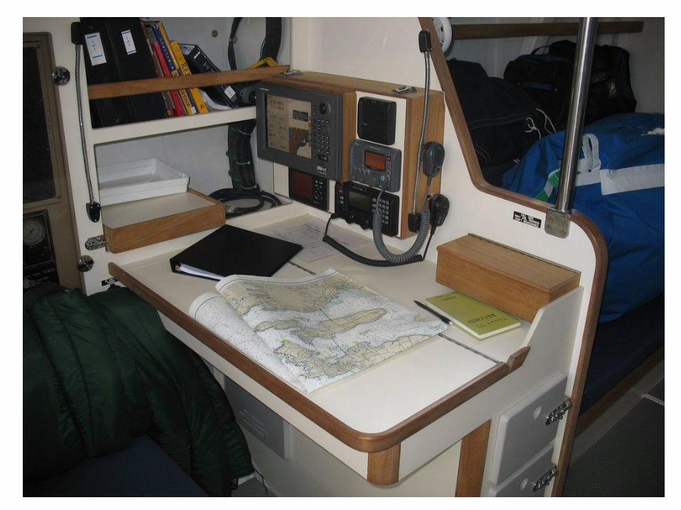
OVERVIEW OF MK II SYSTEMSICOM M-504 VHF Radio
• ICOM VHF (very high frequency) radio used for ship-ship or ship-shore stations for communications and distress calls.
• Equipped with:
– Masthead antenna
– Remote cockpit microphone with independent functions
– DSC (digital select calling) transmitter/receiver

OVERVIEW OF SYSTEMSICOM M-802 SSB Radio
• ICOM SSB (single side-band) or HF (high
frequency) radio for long distance
communications and distress calls.
• Equipped with:
– Insulated antenna mounted on backstay
– Switch in nav station to go from SSB to Fax
– HF automatic antenna tuner
– DSC transmitter

OVERVIEW OF SYSTEMSBrooks & Gatehouse (B&G) Sailing Instruments
• B&G sailing instruments provide speed, depth, and wind information.
• Displays include:– GFD (graphical function display) in nav station
– FFD (full function display) (2) in cockpit on companionway
– Analog (2) display apparent and magnified apparent wind angle
• Sensors that supply information to the system:– Paddlewheel speed sensor (2) and gravity switch
– Depth sensor
– Wind speed/angle sensor
– Sea/air temperature and barometric pressure sensor
– Electronic fluxgate compass

OVERVIEW OF SYSTEMSFuruno
• Furuno NavNet vx2 1834C with GPS.
• Display can be set to full screen, or split to show
two or three different functions. The electronic
chart can be displayed with a radar overlay.
• Functions in this system include:
– Radar
– GPS (mounted on dome)
– Navigation
– WeatherFax (paperless)

SYSTEM INTERFACE
• Electronics are linked through a NMEA 0183 interface, enabling connection of multiple instruments to each other and to a computer.
• Interface is Bluetooth enabled for wireless computer connection.
• What does this mean to you?
• When all systems are operational:– GPS location fed to both radios, so that they will transmit your
location when you push the red distress signals.
– If a laptop is linked into the system, navigational programs like Sperry-Litton (USN) Deckman or Expedition will incorporate info from all systems.

EMERGENCY FEATURES
• Furuno SAVE MOB Man Overboard button
– Hold for three seconds, follow directions on
screen, will display range and bearing to MOB
waypoint
• ICOM VHF DSC distress button
– Hold for five seconds
• ICOM SSB DSC distress button
– Hold for five seconds

MMSI
Mobile Maritime Service Identities• Nine digit “phone numbers” used by maritime Digital
Select Calling (DSC) and Automatic Identification Systems (AIS) to uniquely identify a ship or coast radio station.
• The number is programmed into ship equipment (VHF and SSB).
• MK II has DSC capability to transmit distress signals. This is done by pushing (and holding) the button on each radio that is under the red plastic protective flap.
• The GPS location will be transmitted ONLY if the GPS is turned on. The location can also be entered manually.
• DSC can also transmit non-emergency messages to other DSC equipped vessels.

DSC
Digital Select Calling• All passenger ships and most other ships 300 grt and larger on
international voyages, including all cargo ships, are required to carry DSC- equipped radios;
• Uses direction-finding equipment to locate mariners in distress;
• Provides 2-way VHF communications to vessels within a minimum 20-mile coastal radius;
• Allows simultaneous monitoring of multiple VHF channels;
• Improves interoperability with federal, state and local agencies;
• Currently, the USCG is implementing GMDSS in Sea Area A1.One element of the project is called "Rescue 21", which updates the USCG VHF distress system to include DSC capability & direction finding capabilities.
• Rescue 21 covers USNA operating area, including Sector Hampton Roads, Baltimore, Delaware Bay and Long Island.

AIS
Automatic Identification System
• (AIS), is a maritime digital communication system that continually transmits and receives vessel data over very-high frequencies.
• AIS A is used on commercial vessels, AIS B is used by recreational vessels.
• System identifies traffic by ship name, type, heading and speed. Very useful tool in contact management.

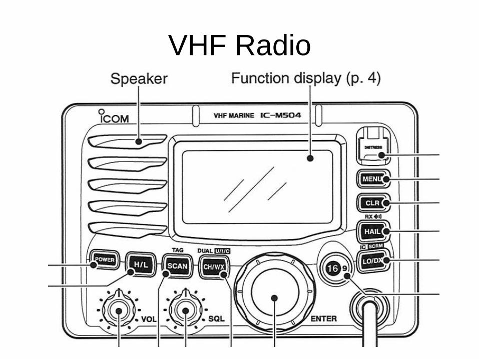
VHF Radio

VHF Radio
• Adjust volume, start with squelch rotated fully counterclockwise.
• Turn breaker on, then power on radio.
• Rotate squelch dial clockwise until noise stops.
• Choose channel you want to transmit on using rotary channel selector dial.
• Ensure you are on high power for long distance comms, or low power for ship to ship (within 1-2 nm).
• Check you have correct “channel group indicator”. Choices are INT, CAN, USA or WX.
• Make call using PTT (push to talk) switch on microphone. Push and hold to transmit, release to receive. TX appears when transmitting, RX = receiving.
• Speak in a normal voice, hold the mic 2-4” away, wait a few seconds before speaking.
• Cautions: – Transmitting without an antenna may damage the transceiver.
– Do not transmit when a person is up the rig.
VHF Radio
• Full function remote mic in cockpit, displays
lat/long, can change channel independently of
main radio.
• Cautions for remote mic:
– Use care when plugging in, only fits one way
– Ensure you are on correct hi/lo setting
– Mic is installed at foot-level, frequently gets kicked
“off” or changes channel
– Ensure you go back to “scan” after using the radio so
you don’t miss comms.

VHF Radio

VHF Radio
Channels:
• While pushing and holding H/L push CH/WX one or more times to select the desired channel group (USA or WX)
• There are 10 weather channels, and 57 USA, 57 International and 61 Canadian channels.
• Some channels are low power only.
• Simplex channels 3, 21, 23, 61, 64, 81, 82 and 83 cannot be lawfully used by the general public.
• Channel 13 is bridge-to-bridge, Channel 16 is emergency, Channel 82A is monitored by the cutter shed “Santee Basin Control, Channel 12 is monitored by SCRD, “Annapolis harbor control”.

VHF Radio
SCAN types:
• Priority scan – searches through all TAG channels in sequence while monitoring Ch 16. If receiving on another channel, call will be interrupted if signal received from Ch 16. If Weather Alert function is turned on, it is included in the scan.
• Weather Alert – ON checks previously used wx channel during standby or while scanning. ON with WX Scan checks all the wx channels in sequence during standby or while scanning.
• Normal scan – searches through all TAG channels in sequence, but will not check Ch 16 unless it is set as a TAG channel.
• Dual-watch – monitors Ch 16 while you receive on another channel.
• Tri-watch – monitors Ch 16 and the call channel while receiving on another channel.
VHF Radio
Distress calls:• VHF Channel 16 – three types. Securite, pan-pan, and mayday.
Listen to USCG calls while underway. If making a call, give pertinent information; location, nature of distress, assistance required, type of vessel, souls on board, injuries.
• DSC Channel 70 – If making a call, lift key cover, push and hold 5 seconds until 1 long beep. Wait for acknowledgement on Ch 70 from a coast station, Ch 16 is automatically selected after ack, make transmission as stated above.
• If receiving a call on DSC Ch 70 – emergency alarm sounds for 2 minutes, push CLR to stop alarm. Ch 16 automatically selected. Alarm will also sound when receiving a distress acknowledgement and distress relay call. Ch 16 automatically selected
VHF Radio
Other functions:• Call channel default is Ch 9, can be programmed. Push 16/9 for 1 second to
select. Push and hold for 3 seconds (wait for 2 beeps and blinking no.) rotate dial to select new call channel, push 16/9 to lock in, CLR to cancel. Suggest 82A
• Microphone functions can be locked to prevent accidental channel changes. Push and hold hi/lo on the mic while turning power ON to toggle lock on/off.
• Display backlight activated by push and hold H/L to adjust brightness of LCD and key backlight – 7 levels and off.
• MMSI number is already programmed into radio, you can check number using DSC menu options. If GPS function is lost, position can be input manually. “Cursor” buttons are on either side of “enter” knob.
• Weather Alert function can be programmed.
• Radio is NOT equipped with optional voice scrambler or external hailer/speaker units, so automatic fog signal function is INOP.

SSB

SSB
CHANNELS:
• 160 user-programmable
• 242 ITU SSB duplex
• 72 ITU SSB simplex
• 662 ITU FSK duplex
When using channel 160, GRP (group) dial changes in 20 channel steps, ie 1-21
Once in the right group, use the (CH) dial to select the channel you want to use.
OR, use the keypad to choose the channel then hit enter. For a (-), hit zero three times.
Channel can be displayed as a channel name and number, or frequency will be displayed.
SSB
• Frequency bands:– 2 MHz band 20-100 miles day or night
– 4 MHz band 20-250 miles day, 150-1500 miles night
– 8 MHz bank 250-1500 miles day, 400-3000 miles night
– 12, 16, 22 and 25 MHz thousands of miles
• SSB ground and sky waves, atmospheric considerations.
• Modes of operation – simplex, both stations tx and rx on same frequency, only one person can talk at a time. Duplex uses two frequencies, tx on one, rx on the other.

SSB
Operating rules and guidelines
• Call procedure– Give your call sign or ship name each time you call
another ship or shore station.
– Repeat your call sign at end of tx longer than 3 minutes
– Break and give call sign every 15 minutes for long calls
– Do not repeat an unanswered call for 2 minutes
• Safety and distress calls take priority over all others.
• Log all safety and distress calls.

SSB
Functions for transmit:
• Transmit frequency check – when duplex used, the transmit
frequency differs from the receive frequency. In this case, the tx
freq should be monitored before tx to prevent interference. F/TX
• Transmit power selection – high, mid, low. High power allows
longer distance, low power reduces power consumption.

SSB
Functions for receive:• Squelch – detects signals with voice components, mutes unwanted signals
(unmodulated beat). Provides quiet standby. SQL off to receive weak signals.
• Noise blanker – reduces pulse type noise (engine). May distort reception of strong signals (NB off)
• AGC –Automatic gain control. Receive gain is automatically adjusted according to rx signal strength with the AGC to prevent distortion from strong signals and to obtain a constant output level. Turn AGC off to get better sensitivity for weak signals.
• RF gain – receiver gain can be reduced with this setting. Helps remove undesired weak signals. Usually the AGC function reduces RF gain according to rx signal strength, however, during no signal reception, weak signals may not be heard, so RF gain can be used for setting a minimum level at which to hear signals.
• Clarity control – voice signals from other stations may be difficult to receive if station is tx slightly off frequency. Push F RX CLAR to turn this function on, adjust with CH dial.
• Tuner through function – allows you to bypass the AT 140 tuner unit to improve receiver gain in a particular frequency band.
SSB
Basic voice transmit and receive:
• Check mic is connected
• No SQL indication
• No xSP indication
• Clarity function off
• Rotate GRP and CH to select receiving channel.
• Adjust volume
• Push MODE set to select desired operation mode
• Push TUNE thru to tune antenna
• Push and hold PTT on mic to transmit
• Release PTT to receive.
SSB
DSC distress call
• MMSI number pre-programmed into radio
• GPS must be turned on to transmit location, or manually enter position.
Push and hold DISTRESS for 5 seconds OR
• Select Distress from DSC menu
• Select Distress Nature from submenu
• Check position and UTC time
• Select frequency
• Push and hold DISTRESS for 5 seconds
SSB equipped with transmit antenna ONLY for DSC.
Emergency frequency 2187.5 automatically selected for tx.
Emergency frequency 2182.0 automatically selected for rx after call transmitted.
B&G
• CPU (central processing unit) core of system, uses dedicated processor to calculate and calibrate functions. Can be linked to a laptop via bluetooth.
• Displays have structured layers of menus. Use arrows up or down to access info, side arrow (or enter) for submenu. Use menu/enter key to input new values. Graphic pages display wind and depth info, can set time period for display.
• Analog displays – Magnified apparent wind angle and apparent wind angle – backlighting controlled by light key on FFD.
B&G
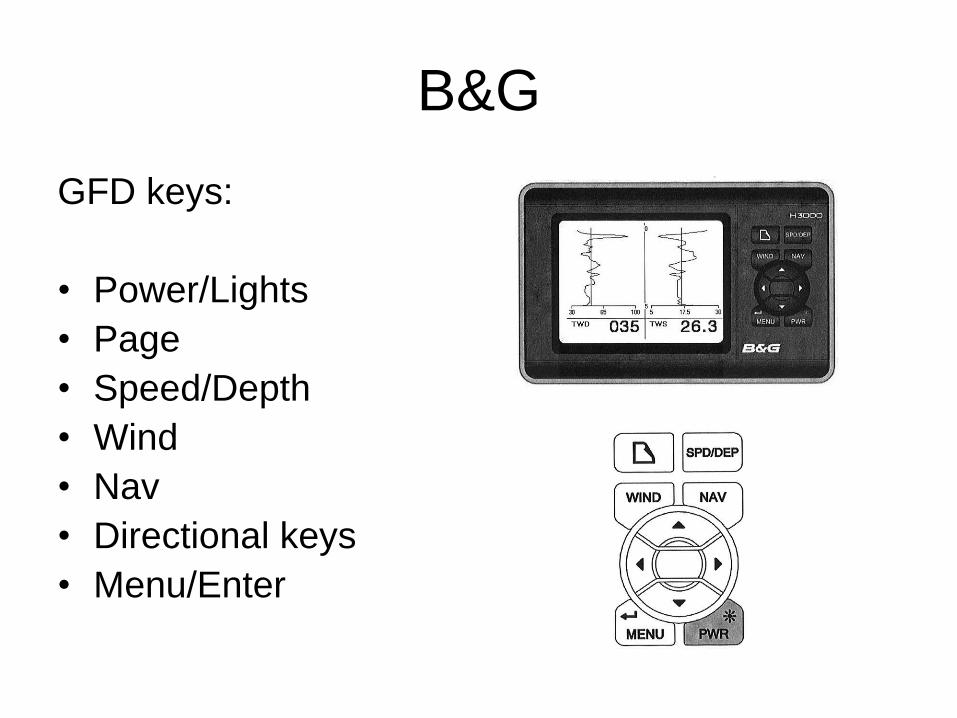
GFD keys:
• Power/Lights
• Page
• Speed/Depth
• Wind
• Nav
• Directional keys
• Menu/Enter
B&G
GFD MENU used to control functions, including:
• Timer – countdown for race starts or time MOB drills
• GPS – data page or rolling road
• (Auto)Pilot – n/a
• Trip Control – log, average speed, timer
• Remote Units – n/a
• Setup

B&G
GFD MENU SETUP:• Alarms
– Low, high and sector angle (heading), depth and true wind speed.
– Alarms cause FFD to flash.
• Units– Heading = degrees magnetic or true
– Wind speed = knots, meters/second
– Depth = meters, feet or fathoms
– Boat speed = knots, km/hour, miles/hr
– Nav mode = great circle, rhumb line
• Calibration and damping

B&G
FFD keys:
• Power/Lights
• Page
• Speed/Depth
• Wind
• Nav
• Directional/Scroll keys
• Menu/Enter

B&G
FFD MENU used to configure a page:
• Using up/down keys, scroll through menus until
“CONFIG DISP” appears
• Press Enter, flashing Page appears
• Press Enter
• To change function in upper display, press Up
then scroll through menus with Up/Down
• Once in desired function, press enter, then press
enter again to save the page configuration.

B&G
Underway concerns:
• Speed paddlewheels– If damaged or inoperable, switch gravity switch in the forward
port locker.
– Substantial marine growth will slow paddlewheel movement, need to clean.
– May pick up seaweed, other flotsam, need to clean.
• Both sensors equipped with self-closing valve to minimize flow of water into boat. – Have plastic dummy plug ready, loosen small inner ring, insert
blanking plug, hand tighten outer ring. Clean paddlewheel carefully with fresh water, soft brush. When ready to reinsert, look for forward arrow, corresponds to notch for proper alignment.

FURUNO NAVNET
• 4 Kw output, radar range of 36 nm
• User friendly operation with combination of discrete keys, soft keys, alphanumeric keys and Trackball.
• Uses a C-MAP NT+/NT MAX SD chart card for the Eastern seaboard, covers from Florida to Maine.
• User programmable function keys.
• The facsimile receiver FAX-30 receives facsimile pictures and navtex messages transmitted from facsimile and navtex stations.
• Compatible with AIS system.

Furuno Function
• Turn on NavNet breaker on panel
• Press “Power/Brill” momentarily to turn power
on; shows the soft keys for adjustment of
brilliance; shows RADAR STBY/TX soft key.
(Note, no toggle switch on radar dome like MK I)
• The hue can be adjusted for radar and plotter
based on the time of day or night.
• To turn off, press and hold the “Power/Brill” key
for 3 seconds.
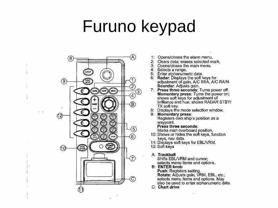
Furuno keypad

Soft Key Functions
• The function of the five soft keys changes
according to the operation. Their labels for
their current functions are shown on the
screen to the left of the keys. To hide or
show the soft keys, press the HIDE/SHOW
key. Each press of the key shows preset
soft keys, user function keys or turns off
navigation information (at the top of the
screen).

SD Chart Card
• The electronic chart card should be
already installed and will remain in the
boat for the duration of your block.
• Do not insert or remove the card when the
power is on.
• Do not remove the card while a chart is
being drawn.

Color Video Plotter
• Display modes– Radar
– Plotter
– Navigation Data
– Overlay
– Weather Fax
• Screen – Full image
– Half screens
– Half screen and two quarter screens
• Hot pages are user-arrangeable displays

Color Video Plotter
• Data boxes, providing nav data, may be shown on any full screen display. Up to six boxes may be viewed. (suggest setting up to display info required for log book)
• Boxes may be rearranged, hidden or temporarily erased to see background info.
• Function keys for radar and plotter are accessed by soft key hide/show, can be individually programmed.

MOB
• Man overboard mark works from any mode except Nav Data, when playing back data or conducting any test.
• Push “Save MOB” button for five seconds (follow directions on screen)
• Select “Go to MOB” from prompt on screen
• Data box with range and bearing to MOB waypoint will be displayed on screen.

Weather Fax
• Equipment receives one fax image or navtex message at a time.
• Paperless
• Three receiving modes are available:– Facsimile
– Navtex
– Facsimile(timer) and navtex
• Can be used with a laptop computer
• Fax will receive during next scheduled broadcast, takes 30-40 minutes to download, images stored as thumbnails.
• Can preview image, manually start or stop receiving image, fine tune rx frequency.
• Up to 12 images on two pages can be stored, when new image received, oldest image is deleted. An image can be locked to prevent deletion.
• Up to 320 channels can be stored

Weather Fax
• Set antenna switch on FAX
• Use menu to turn GGA, GLL, and ZDA on
• Select WXFAX display
• Choose the receive mode (fax, navtex or
timer/navtex)
• Choose area/station to receive weather from
• Set timer if desired.
• Monitor battery level after receiving, may need to
charge batteries.
NAVTEX
• Navtex stations around the world provide mariners with weather and navigational navtex messages. There are different categories of messages, denoted by a character code.
• It is recommended to receive the categories:– A – coastal navigation warning
– B – meteorlogical warning
– D – search and rescue alert
– L – navarea warnings
• Set station and message type, can set alarms for warning messages.
• Information broadcast 4 times/day by USCG
Radar
• Radar dome can be manually adjusted when heeled over so that dome is level.
• There is no toggle on/off switch on the dome
• Keep radar on standby when not in use to minimize power drain.
Furuno model-specific notes:
• If IR function is turned on, radar will not pick up Racon buoys/beacons
• Sea clutter has auto tune, recommended to self-tune. The gain is sensitive, so better to have the gain turned down, clutter up.
• If the B&G heading function goes down, the overlay will be lost. To remedy, turn Furuno off then back on.
Radar

Radar
• Tuning – can be automatic or manual
• Gain Adjustment – proper setting is such that
background noise is just visible on the screen
• Sea Clutter – echos from waves, may mask
targets, adjust A/C SEA to suppress clutter.
• Rain Clutter – radar can be used to track
incoming weather, adjust A/C RAIN when the
precipitation masks solid targets

Radar
• Range scale – setting determines the size of the area in nm that will appear on display.
• Range setting will automatically adjust the range ring interval so that accurate range measurements may be made.
• Maximum range of this model is 36 nm.
• Pulse length – preset to individual range scales. May select longer pulse of longer detection range or shorter pulse for better range discrimination.

Radar
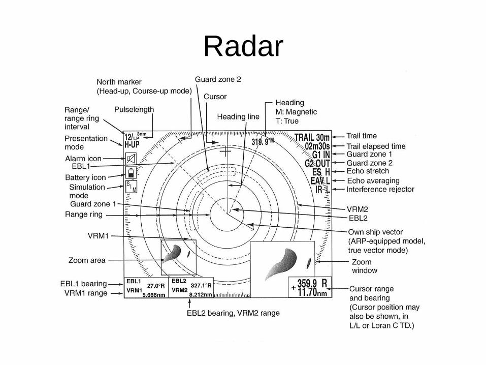
Presentation modes: displayed in upper left corner of screen.
• North up – north is maintained at the top of the screen.
• True motion – fixed radar targets maintain position on the screen, ship moves across radar images.
• Head up – line connecting radar center with top of display is the ship’s heading. North marker is a short line on the bearing scale.
• Course up – the currently selected course is at the top of the screen.
Radar
Measuring Range:
• Range rings
• Cursor
• VRM (Variable Range Marker)

Radar
Measuring Bearing:
• Cursor
• EBL (Electronic Bearing Line)
– The bearing to a target may be shown relative to own
ship’s heading (Relative) or True bearing (requires
heading data). Setup with EBL reference.
– Offset EBL can be used to predict a potential collision
course. It can also be used to measure range and
bearing between 2 targets.

Radar
• Noise Interference – adjust off, low, high.
• Radar Interference – may occur when
near another shipborne radar operation on
same frequency band. Turn on to
eliminate, turn off when not needed so that
weak targets are not missed.
• Zoom feature allows you to double size of
area selected.
Radar
• Echo Trails – simulated afterglow of target
echos that represent their movement
relative or true to their own ship. Useful
for collision prevention.
• Echo Stretch – function magnifies small or
weak targets. Also magnifies sea clutter
and radar interference so adjust
accordingly.

Radar
• Guard Alarm – allows operator to set desired range and bearing for a guard zone. Audio alarm and target blinks.
• Guard zone – if targets are inside the zone when you set it up, the alarm will only sound for outgoing targets. Set up zone while all targets are outside so that the alarm is triggered by targets entering the zone.
• Watchman – periodically transmits radar pulses for one minute to check for targets in a guard zone. Operator sets standby time period.

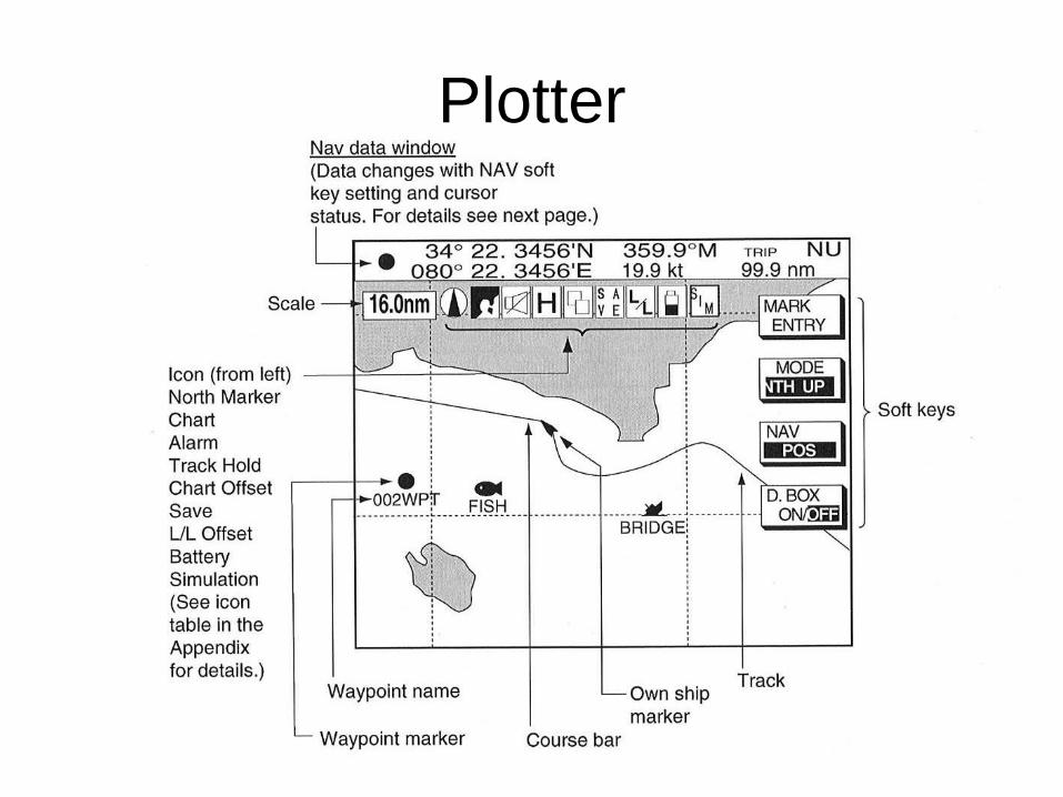
Plotter
• Plotter display may be full screen, in overlay with
radar display, or in a combination screen.
• Nav graphic display shows the compass display
or the wind display depending on setting
chosen.
• Highway display shows graphic display of ship
track along course. Cross track error monitor
available.
• Nav data display may be user selected
Plotter
• Icon for position data important
– cross - cursor position
– dot - own ship position
– dot in square – waypoint position
Plotter

Plotter
Presentation modes:
• North up
• Course up
• Auto course up
• Perspective (C-Map only) – chart data is
projected in perspective mode for 3D
simulation.
Plotter
• Shifting the display can be accomplished by moving the trackball to the edge of the screen
• Press CENTER soft key to return ship marker to center of screen
• C-MAP provides tide height calculations (place cursor over tide icon, use submenus)
• Track – own ship’s track is plotted by default. Track can be erased, color coded, interval set. Only certain amount of memory, oldest erased first.
• Marks and lines may be entered on a chart to mark a location of interest.
Waypoints
• Furuno uses permanent waypoints and quickpoints.
• 999 waypoints available
• Five methods of entering:– At own ship position
– At MOB position
– By cursor
– By range and bearing
– Through waypoint list
• Waypoint list organized in Alphanumeric order
Routes
• Up to 200 routes with 35 waypoints each can be stored.
• A route can be created:
– Using existing waypoints
– With the cursor
– Voyage based (retrace previous track)
• Routes may be connected
• Waypoints can be inserted into existing route.

Alarms
• Audio and visual alarms may be set
• Arrival (at waypoint)
• Anchor watch
• Cross track error
• Speed
• Proximity alarm (to waypoint)
• Trip log alarm
• Grounding alarm