Embed Size (px)
Citation preview
Naveed Habib KhanNaveed Habib KhanMechanical Mechanical DepartmentDepartment
6th August 20096th August 2009
WELDINGWELDINGWELDINGWELDING
Welding BasicsWelding Basics Types of Weld JointsTypes of Weld Joints Welding PositionsWelding Positions Welding TypesWelding Types Welding ProcessesWelding Processes Welding SymbolsWelding Symbols Welding SafetyWelding Safety
ContentsContents

FabricationFabrication““Metal Fabrication is the forming of metal, usually steel plate, into Metal Fabrication is the forming of metal, usually steel plate, into various forms either by welding or other forms of metal joining processesvarious forms either by welding or other forms of metal joining processes
WeldingWelding
““A fabrication process that joins materials, usually metals by A fabrication process that joins materials, usually metals by causing coalescence”causing coalescence”
Coalescence meansCoalescence means “Fusion” “Fusion”
What is Fabrication / What is Fabrication / Welding?Welding?
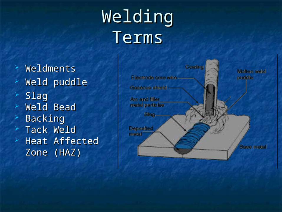
WeldmentsWeldments Weld puddleWeld puddle SlagSlag Weld BeadWeld Bead BackingBacking Tack WeldTack Weld Heat Affected Zone Heat Affected Zone
(HAZ)(HAZ)
Welding Welding TermsTerms
5
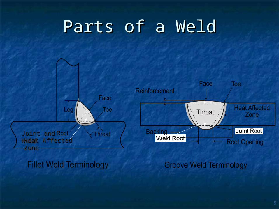
Parts of a WeldParts of a Weld
Joint and WeldJoint and WeldHeat Affected ZoneHeat Affected Zone

6
Fillet WeldFillet Weld Fillet welds should: Fillet welds should:
Have a flat to slightly convex faceHave a flat to slightly convex face Be uniform in appearanceBe uniform in appearance Have equal leg sizeHave equal leg size
7
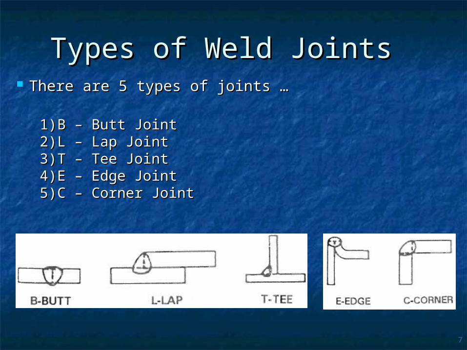
Types of Weld Joints Types of Weld Joints There are 5 types of joints …There are 5 types of joints …
1)1) B – Butt JointB – Butt Joint2)2) L – Lap JointL – Lap Joint3)3) T – Tee Joint T – Tee Joint 4)4) E – Edge JointE – Edge Joint5)5) C – Corner JointC – Corner Joint
8
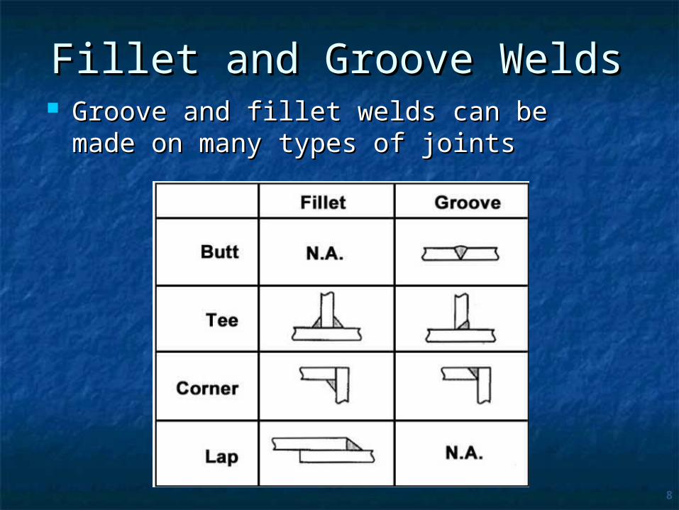
Fillet and Groove WeldsFillet and Groove Welds Groove and fillet welds can be made on Groove and fillet welds can be made on
many types of jointsmany types of joints

9
Types of Joints Types of Joints
WELDED JOINT CATEGORYWELDED JOINT CATEGORY ASME Code defines welded joints by category. The term “Category” defines the location of a joint in a The term “Category” defines the location of a joint in a
vessel.vessel. The joints included in each category are designated as The joints included in each category are designated as
joints of Categories A, B, C, and D. joints of Categories A, B, C, and D. The “Categories” established by UW-3 are for use in The “Categories” established by UW-3 are for use in
specifying special requirements (based on Service, specifying special requirements (based on Service, Material, and Thickness) regarding joint type and Material, and Thickness) regarding joint type and degree of inspection for certain welded pressure joints.degree of inspection for certain welded pressure joints.
Weld joint efficiency “E” It is a measure of weld quality and accounts for
stress concentrations. E is needed in component thickness calculations

Figure illustrates typical joint locations included in each Figure illustrates typical joint locations included in each category.category.
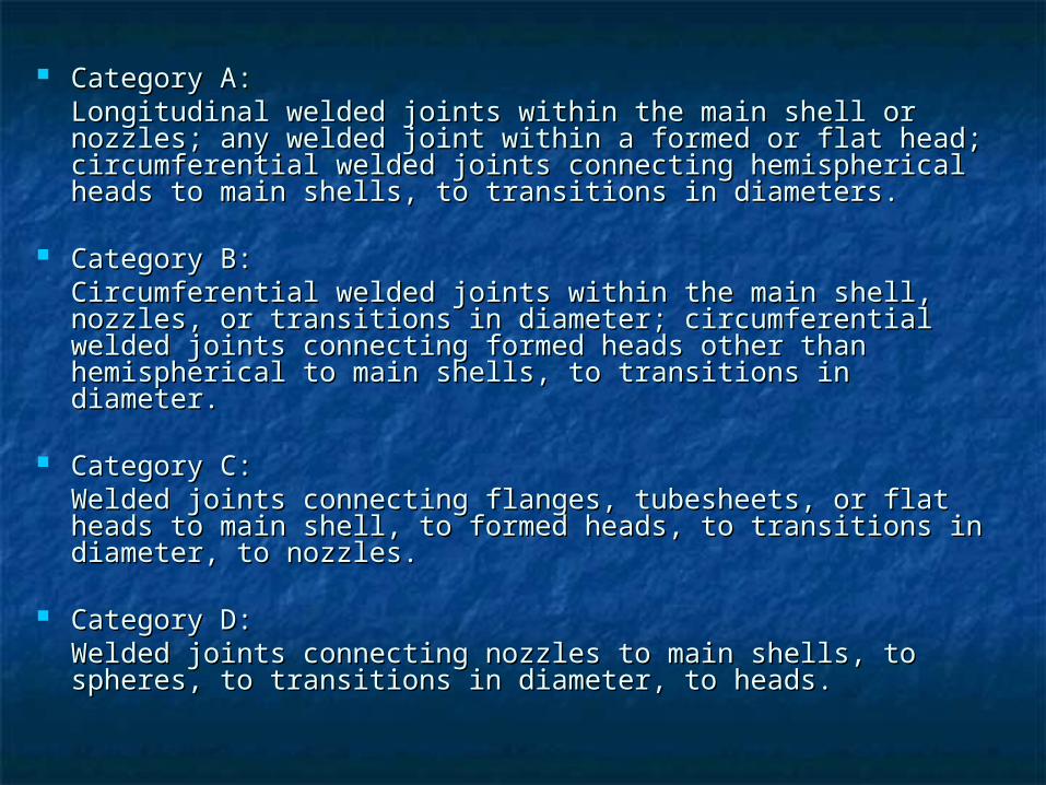
Category A:Category A:Longitudinal welded joints within the main shell or Longitudinal welded joints within the main shell or nozzles; any welded joint within a formed or flat head; nozzles; any welded joint within a formed or flat head; circumferential welded joints connecting hemispherical circumferential welded joints connecting hemispherical heads to main shells, to transitions in diameters.heads to main shells, to transitions in diameters.
Category B:Category B:Circumferential welded joints within the main shell, Circumferential welded joints within the main shell, nozzles, or transitions in diameter; circumferential welded nozzles, or transitions in diameter; circumferential welded joints connecting formed heads other than hemispherical joints connecting formed heads other than hemispherical to main shells, to transitions in diameter. to main shells, to transitions in diameter.
Category C:Category C:Welded joints connecting flanges, tubesheets, or flat Welded joints connecting flanges, tubesheets, or flat heads to main shell, to formed heads, to transitions in heads to main shell, to formed heads, to transitions in diameter, to nozzles.diameter, to nozzles.
Category D:Category D:Welded joints connecting nozzles to main shells, to Welded joints connecting nozzles to main shells, to spheres, to transitions in diameter, to heads.spheres, to transitions in diameter, to heads.

Weld joint efficiency vs. Joint Type, Category & Radiographic Examination
14
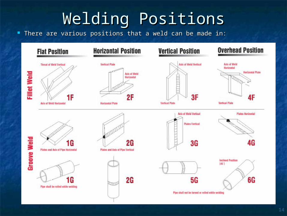
Welding PositionsWelding Positions There are various positions that a weld can be made in:There are various positions that a weld can be made in:

Root Pass Hot Pass
Fill Pass Cover Pass
Weld Passes

TYPES OF WELDING
APPLICATION PROCESS
CONSTRUCTION IN-SERVICE ARC GAS
RESISTANCE SOLID STATE
ENERGY BEAM
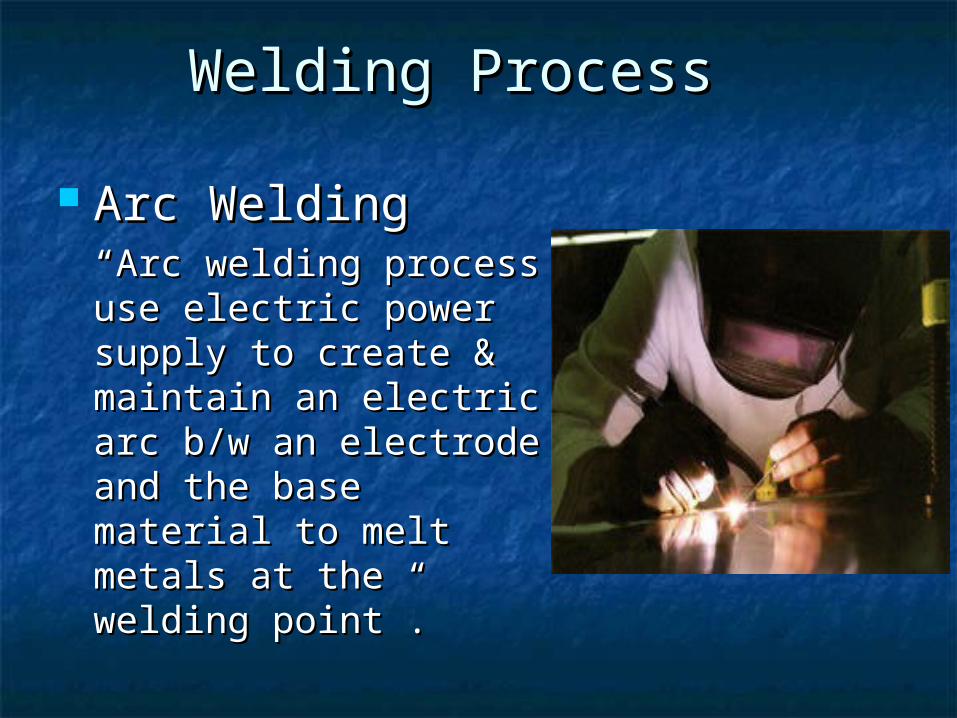
Arc Welding Arc Welding ““Arc welding process Arc welding process use electric power use electric power supply to create & supply to create & maintain an electric arc maintain an electric arc b/w an electrode and b/w an electrode and the base material to the base material to melt metals at the melt metals at the welding point”.welding point”.
Welding ProcessWelding Process
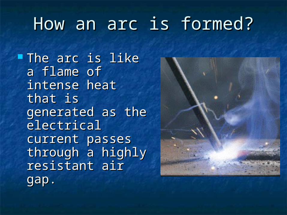
How an arc is formed?How an arc is formed?
The arc is like a The arc is like a flame of intense flame of intense heat that is heat that is generated as generated as the electrical the electrical current passes current passes through a highly through a highly resistant air gap.resistant air gap.
19
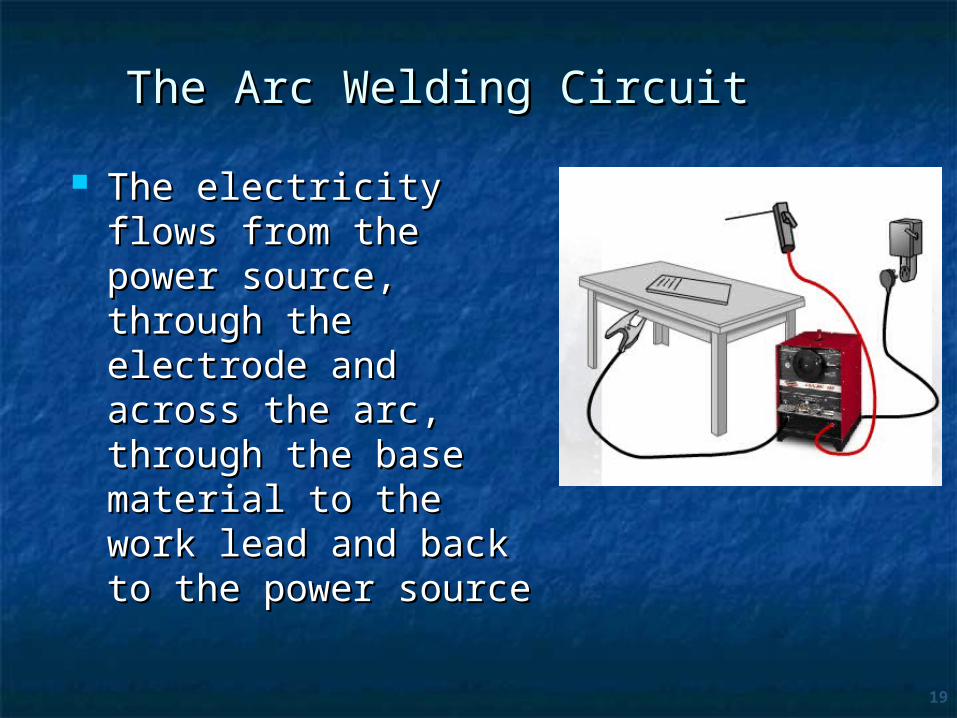
The Arc Welding CircuitThe Arc Welding Circuit
The electricity flows The electricity flows from the power from the power source, through the source, through the electrode and across electrode and across the arc, through the the arc, through the base material to the base material to the work lead and back to work lead and back to the power sourcethe power source
20
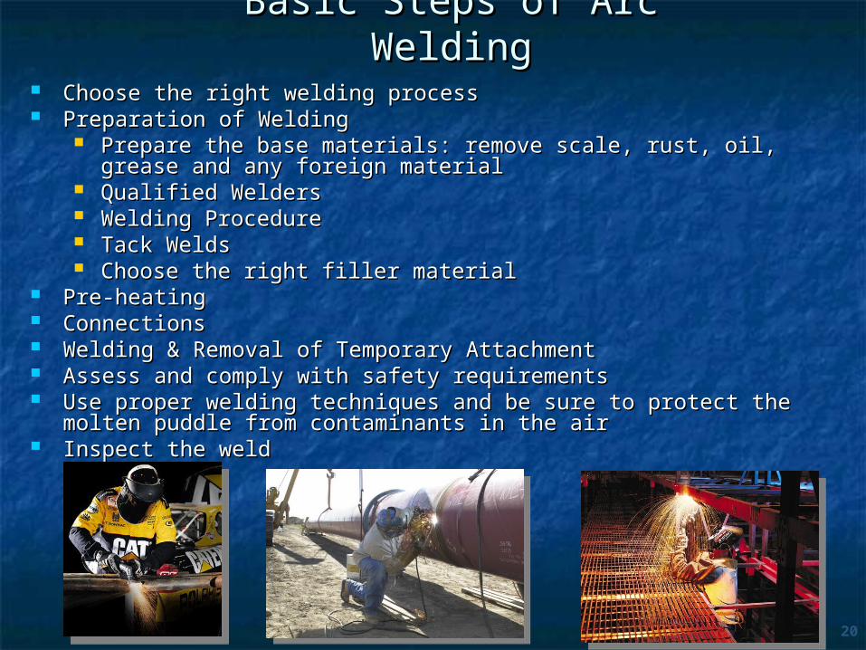
Basic Steps of Arc WeldingBasic Steps of Arc Welding Choose the right welding processChoose the right welding process Preparation of WeldingPreparation of Welding
Prepare the base materials: remove scale, rust, oil, grease and Prepare the base materials: remove scale, rust, oil, grease and any foreign materialany foreign material
Qualified WeldersQualified Welders Welding ProcedureWelding Procedure Tack WeldsTack Welds Choose the right filler materialChoose the right filler material
Pre-heatingPre-heating ConnectionsConnections Welding & Removal of Temporary AttachmentWelding & Removal of Temporary Attachment Assess and comply with safety requirementsAssess and comply with safety requirements Use proper welding techniques and be sure to protect the molten Use proper welding techniques and be sure to protect the molten
puddle from contaminants in the airpuddle from contaminants in the air Inspect the weldInspect the weld
Factors Affecting the Factors Affecting the WeldingWelding
1.1. Welding ProcedureWelding Procedure2.2. ThicknessThickness3.3. Electrode extensionElectrode extension4.4. Angle of bevelAngle of bevel5.5. Travel speedTravel speed6.6. CleanlinessCleanliness 7.7. Type of jointType of joint8.8. Polarity, Current & Voltage Polarity, Current & Voltage 9.9. Root Opening distanceRoot Opening distance10.10. Welding PositionWelding Position

Types of Arc Welding Types of Arc Welding
Shielded Metal - Arc WeldingShielded Metal - Arc Welding (SMAW) (SMAW) Gas Metal - Arc WeldingGas Metal - Arc Welding (GMAW)(GMAW) Gas Tungsten - Arc WeldingGas Tungsten - Arc Welding (GTAW)(GTAW) Submerged - Arc WeldingSubmerged - Arc Welding(SAW)(SAW) Plasma - Arc WeldingPlasma - Arc Welding (PAW)(PAW) Flux Cored - Arc WeldingFlux Cored - Arc Welding (FCAW)(FCAW)
GAS WELDINGGAS WELDING Oxyacetylene WeldingOxyacetylene Welding (OAW)(OAW)

Gas Tungsten Arc Welding (GTAW)Gas Tungsten Arc Welding (GTAW)
Also called TAlso called Tungsten inert gas (TIG) This uses a similar inert gas shield to MIG, but the tungsten electrode is not consumed. Filler metal is provided from a separate rod fed automatically into the molten pool
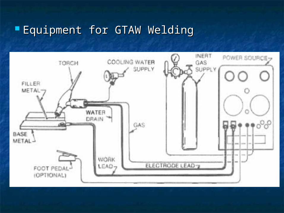
Equipment for GTAW WeldingEquipment for GTAW Welding
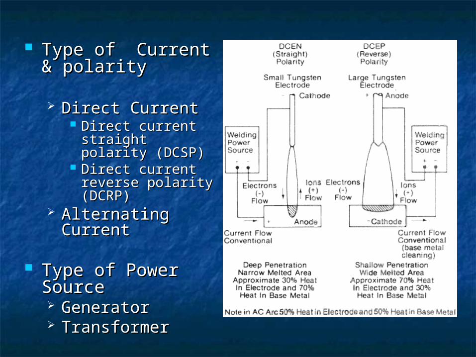
Type of Current & Type of Current & polaritypolarity
Direct CurrentDirect Current Direct current Direct current
straight polarity straight polarity (DCSP)(DCSP)
Direct current Direct current reverse polarity reverse polarity (DCRP)(DCRP)
Alternating Alternating CurrentCurrent
Type of Power Type of Power SourceSource GeneratorGenerator TransformerTransformer
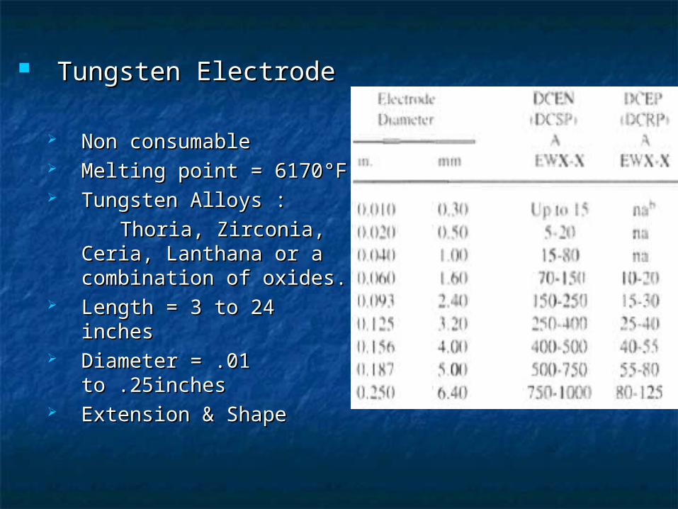
Tungsten ElectrodeTungsten Electrode
Non consumableNon consumable Melting point = 6170Melting point = 6170°F°F Tungsten Alloys : Tungsten Alloys :
Thoria, Zirconia, Ceria, Thoria, Zirconia, Ceria, Lanthana or a Lanthana or a combination of oxides.combination of oxides.
Length = 3 to 24 Length = 3 to 24 inchesinches
Diameter = .01 Diameter = .01 to .25inchesto .25inches
Extension & ShapeExtension & Shape
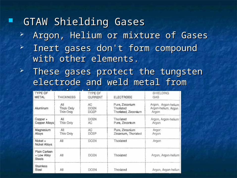
GTAW Shielding GasesGTAW Shielding Gases Argon, Helium or mixture of GasesArgon, Helium or mixture of Gases Inert gases don't form compound with Inert gases don't form compound with
other elements.other elements. These gases protect the tungsten These gases protect the tungsten
electrode and weld metal from electrode and weld metal from contamination.contamination.

Properties Of Inert GasesProperties Of Inert GasesProperties of Argon Properties of HeliumArgon is a heavy gas that is obtained from the atmosphere by the liquification of air
Helium is a light gas that is obtained by separation from natural gas
May be used as a compressed gas May be used as a compressed gas
Quieter & smoother arc action Deeper penetration
Lower cost Expensive
Suitable gas for GTAW Gives a smaller heat affected zone
Better for thin metals Better for thicker metals
Good cleaning action
Lower flow rates are required Higher flow rates are required
Better for welding dissimilar metals
More availability Less available
Better for welding at higher speeds
Argon - helium mixture are used when better control of argon and the deeper penetration of helium are needed. (75% helium, 25% Argon)
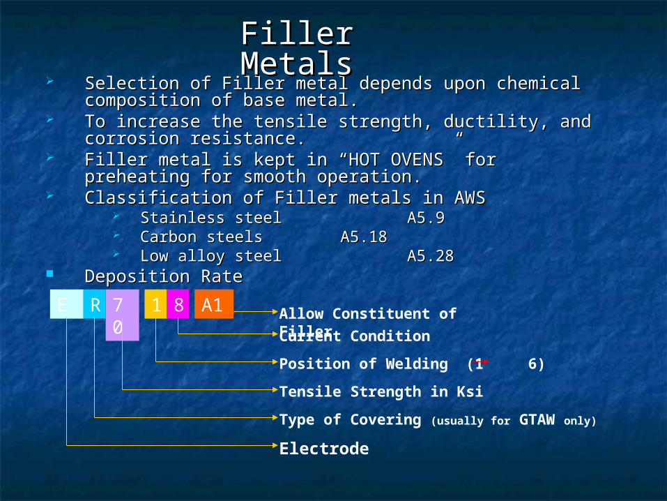
E 70 1 8R
Electrode
Type of Covering (usually for GTAW only)
Tensile Strength in Ksi
Position of Welding (1 6)
Current Condition
A1 Allow Constituent of Filler
Selection of Filler metal depends upon chemical Selection of Filler metal depends upon chemical composition of base metal.composition of base metal.
To increase the tensile strength, ductility, and corrosion To increase the tensile strength, ductility, and corrosion resistance. resistance.
Filler metal is kept in “HOT OVENS” for preheating for Filler metal is kept in “HOT OVENS” for preheating for smooth operation.smooth operation.
Classification of Filler metals in AWSClassification of Filler metals in AWS Stainless steelStainless steel A5.9A5.9 Carbon steelsCarbon steels A5.18A5.18 Low alloy steelLow alloy steel A5.28A5.28
Deposition RateDeposition Rate
Filler MetalsFiller Metals
Cost of GTAWCost of GTAW LaborLabor (20% to 40%)(20% to 40%) Overhead costOverhead cost (Major Cost)(Major Cost) Filler metal costFiller metal cost Shielded gas costShielded gas cost Electric power costElectric power cost (Minor cost)(Minor cost) Tungsten Electrode costTungsten Electrode cost
(4%of Shielding gas cost)(4%of Shielding gas cost) Welding TorchWelding Torch

AdvantagesAdvantages High Quality WeldHigh Quality Weld No Flux or SlagNo Flux or Slag Used for both Ferrous & Non-Ferrous metalsUsed for both Ferrous & Non-Ferrous metals No Smokes or FumesNo Smokes or Fumes Welding can be done in all positionWelding can be done in all position Filler metal is not always requiredFiller metal is not always required The arc & weld pool is clearly visible to the The arc & weld pool is clearly visible to the
welderwelder For many application, it is the best methodFor many application, it is the best method Excellent for welding thin metals and pipeline
welding

LimitationsLimitations Welding speed is slowWelding speed is slow Electrode is easily contaminatedElectrode is easily contaminated Not efficient for welding thick sectionsNot efficient for welding thick sections
Thickness should not exceed ¾”.Thickness should not exceed ¾”.
Lower filler metal deposition rateLower filler metal deposition rate Not EconomicalNot Economical Hand eye co-ordination skill is requiredHand eye co-ordination skill is required Highly skilled labor needed for this processHighly skilled labor needed for this process

Shielded Metal Arc WeldingShielded Metal Arc Welding(SMAW)(SMAW)
This is the most commonly used technique. There is a wide choice of electrodes, metal and fluxes, allowing application to different welding conditions.
The gas shield is evolved from the flux, preventing oxidation of the molten metal pool.
Also referred to as “Stick Welding”Also referred to as “Stick Welding”
Used for everything from pipeline welding, farm repair and Used for everything from pipeline welding, farm repair and complex fabrication.complex fabrication.
Uses a “stick” shaped electrode. Uses a “stick” shaped electrode. Can weld: steel, cast iron, stainless steel, etc.Can weld: steel, cast iron, stainless steel, etc.
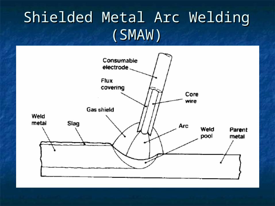
Shielded Metal Arc Welding Shielded Metal Arc Welding (SMAW)(SMAW)
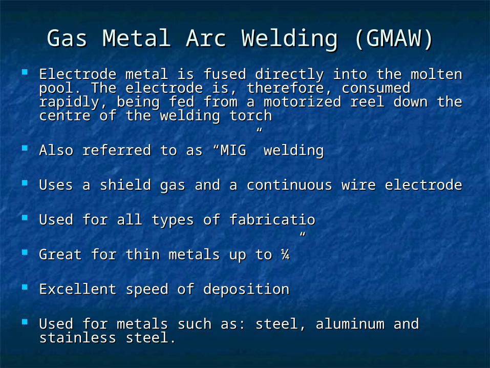
Gas Metal Arc Welding (GMAW)Gas Metal Arc Welding (GMAW) Electrode metal is fused directly into the molten pool. The Electrode metal is fused directly into the molten pool. The
electrode is, therefore, consumed rapidly, being fed from a electrode is, therefore, consumed rapidly, being fed from a motorized reel down the centre of the welding torchmotorized reel down the centre of the welding torch
Also referred to as “MIG” weldingAlso referred to as “MIG” welding
Uses a shield gas and a continuous wire electrodeUses a shield gas and a continuous wire electrode
Used for all types of fabricatioUsed for all types of fabricatio
Great for thin metals up to ¼”Great for thin metals up to ¼”
Excellent speed of depositionExcellent speed of deposition
Used for metals such as: steel, aluminum and stainless steel.Used for metals such as: steel, aluminum and stainless steel.
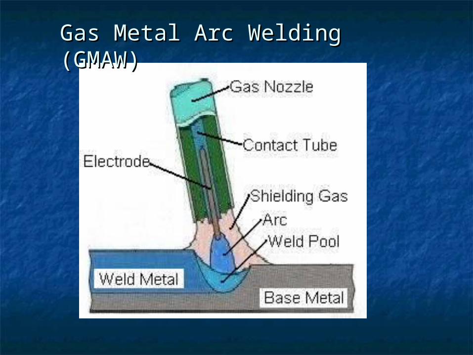
Gas Metal Arc Welding Gas Metal Arc Welding (GMAW)(GMAW)
Higher deposition rates than SMAW Higher deposition rates than SMAW All position capability All position capability Less operator skill required Less operator skill required Long welds can be made without starts and stops Long welds can be made without starts and stops Minimal post weld cleaning is required Minimal post weld cleaning is required
MIG Welding BenefitsMIG Welding Benefits
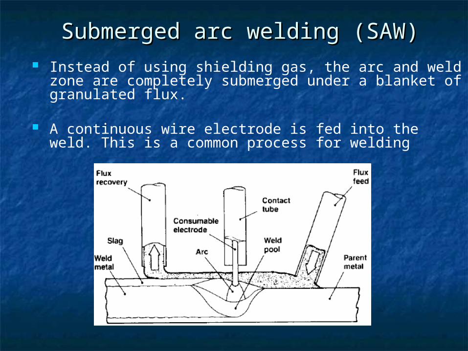
Instead of using shielding gas, the arc and weld zone are completely submerged under a blanket of granulated flux.
A continuous wire electrode is fed into the weld. This is a common process for welding
Submerged arc welding (SAW)Submerged arc welding (SAW)

This is similar to the MIG process, but uses a continuous hollow electrode filled with flux, which produces the shielding gas.
The advantage of the technique is that it can be used for outdoor welding, as the gas shield is less susceptible to draughts.
Flux-cored arc welding Flux-cored arc welding (FCAW)(FCAW)
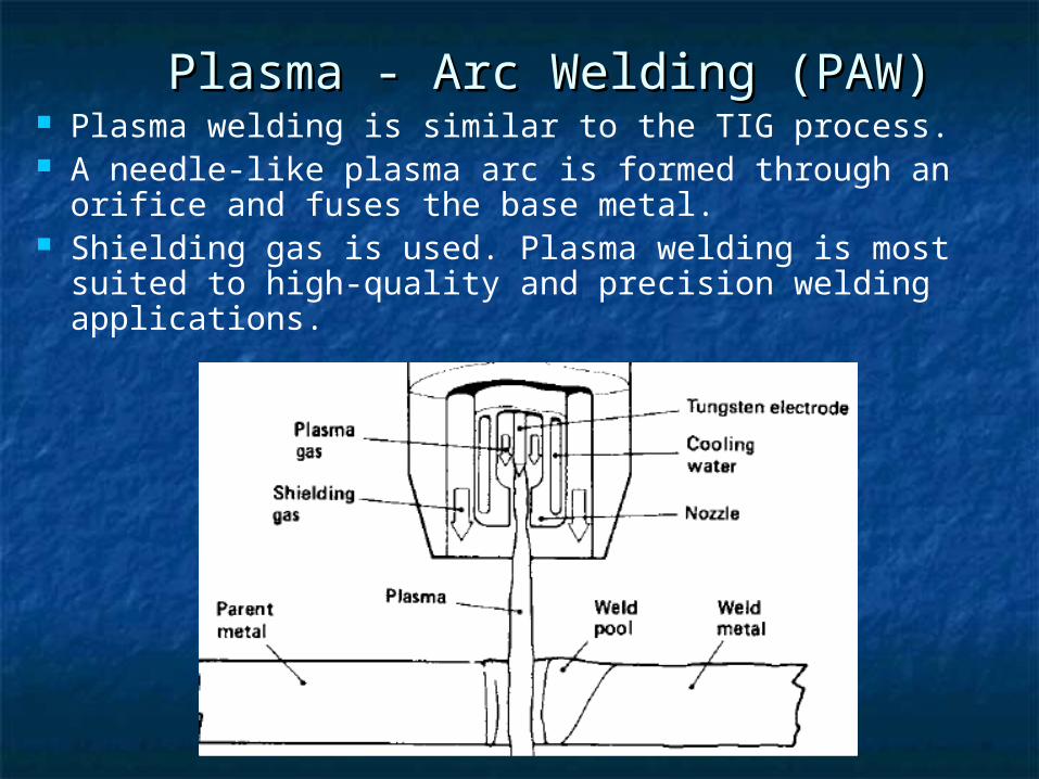
Plasma welding is similar to the TIG process. A needle-like plasma arc is formed through an orifice
and fuses the base metal. Shielding gas is used. Plasma welding is most suited
to high-quality and precision welding applications.
Plasma - Arc Welding (PAW)Plasma - Arc Welding (PAW)
Oxygen/ Fuel WeldingOxygen/ Fuel Welding
Utilizes oxygen and a fuel gas to heat metal Utilizes oxygen and a fuel gas to heat metal until it is in a molten state and fuse multiple until it is in a molten state and fuse multiple pieces of metal together. Can be used with or pieces of metal together. Can be used with or without a filler rod.without a filler rod.
Great for brazing dissimilar metals together.Great for brazing dissimilar metals together. Older technology that can be replaced by Older technology that can be replaced by
GTAWGTAW

42
Welding SymbolsWelding SymbolsWelding symbols contain information about the weld to be madeWelding symbols contain information about the weld to be made

43
Welding symbols give the welder specific instructions about Welding symbols give the welder specific instructions about the weld including:the weld including: Placement, Size, Length, ProcessPlacement, Size, Length, Process Any other special notesAny other special notes
Welding symbols areWelding symbols are Universally usedUniversally used Governed by the AWSGoverned by the AWS Found on engineering drawingsFound on engineering drawings

Reference Line (Required element)
Reference LineReference Line
Always Horizontal

Reference Line (Required element)
Arrow
Arrow LineArrow Line

Reference Line (Required element)
Arrow
Tail
TailTail

Reference Line (Required element)
Arrow
Tail
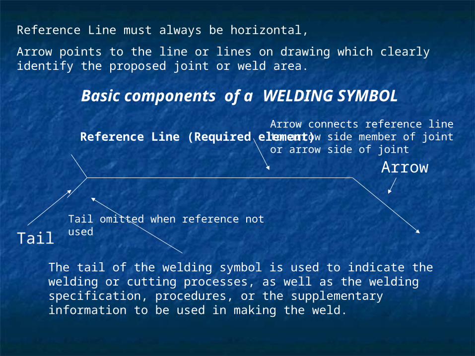
Reference Line must always be horizontal,
Arrow points to the line or lines on drawing which clearly identify the proposed joint or weld area.
The tail of the welding symbol is used to indicate the welding or cutting processes, as well as the welding specification, procedures, or the supplementary information to be used in making the weld.
Reference Line (Required element)
Arrow
Tail
Reference Line must always be horizontal,
Arrow points to the line or lines on drawing which clearly identify the proposed joint or weld area.
The tail of the welding symbol is used to indicate the welding or cutting processes, as well as the welding specification, procedures, or the supplementary information to be used in making the weld.
Basic components of a WELDING SYMBOL
Tail omitted when reference not used
Arrow connects reference line to arrow side member of joint or arrow side of joint
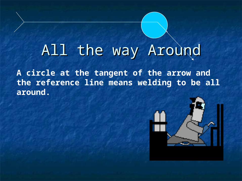
A circle at the tangent of the arrow and the reference line means welding to be all around.
All the way AroundAll the way Around
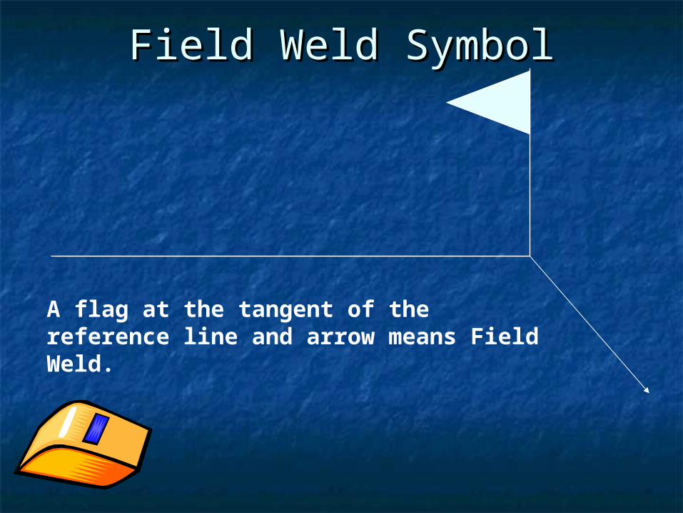
A flag at the tangent of the reference line and arrow means Field Weld.
Field Weld SymbolField Weld Symbol

ARROW SIDE
OTHER SIDE
Weld Symbol TerminologyWeld Symbol Terminology

Break in arrow means arrow Break in arrow means arrow side must be side that side must be side that
beveling or other beveling or other preparation required.preparation required.

Fillet Weld (Arrow Side Only)Fillet Weld (Arrow Side Only)
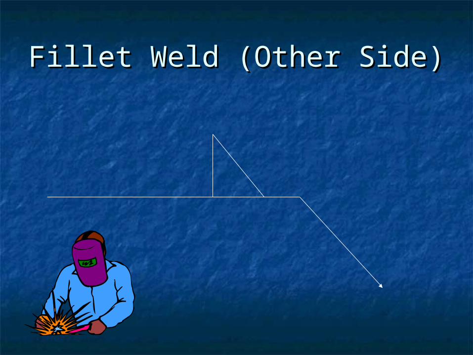
Fillet Weld (Other Side)Fillet Weld (Other Side)

1/4
1/4
Size of Fillet WeldSize of Fillet Weld

1/4
1/4
(5/16)
(5/16)
Depth of preparation or groove
Depth of penetration
Example of Double Bevel Groove Example of Double Bevel Groove weldweld
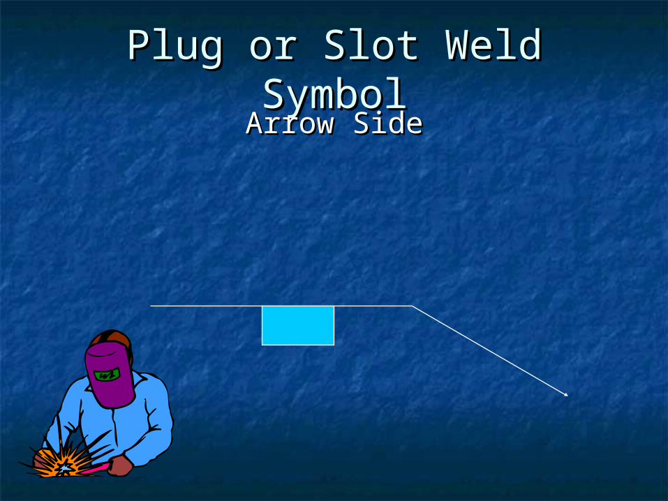
Plug or Slot Weld SymbolPlug or Slot Weld SymbolArrow SideArrow Side

5/16
5/16
Single-Bevel-Groove and Single-Bevel-Groove and Double Fillet Weld SymbolDouble Fillet Weld Symbol

Single-Bevel-Groove and Single-Bevel-Groove and Double Fillet weld SymbolsDouble Fillet weld Symbols
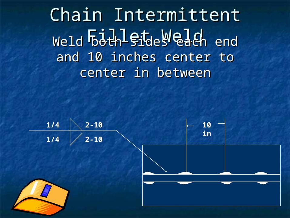
Chain Intermittent Fillet Chain Intermittent Fillet WeldWeldWeld both sides each end and Weld both sides each end and
10 inches center to center in 10 inches center to center in betweenbetween
1/4
1/4
2-10
2-10
10 in
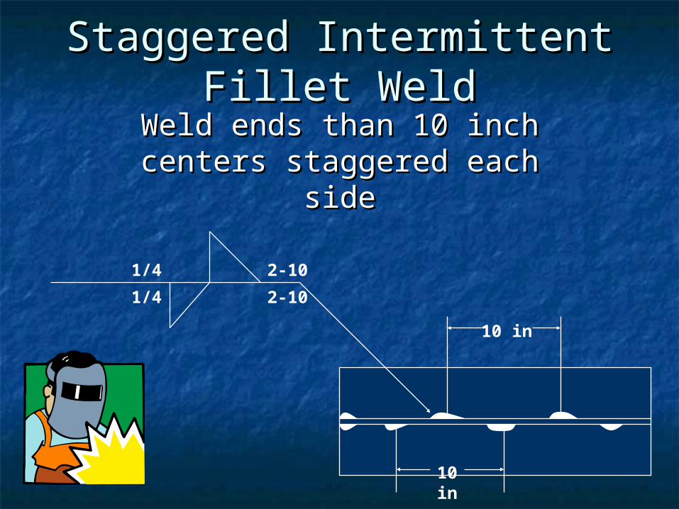
Staggered Intermittent Staggered Intermittent Fillet WeldFillet Weld
Weld ends than 10 inch Weld ends than 10 inch centers staggered each sidecenters staggered each side
10 in
10 in
2-10
2-101/4
1/4

Standard Weld SymbolsStandard Weld SymbolsAs per AWS 2.4-1998As per AWS 2.4-1998

Some common symbol List published by AWS

Back PurgingBack Purging Back Purging ProcedureBack Purging Procedure Used to protect the electrode and the molten weld metal Used to protect the electrode and the molten weld metal
from atmospheric contaminationfrom atmospheric contamination Protect the underside of the weld & its adjacent base metal Protect the underside of the weld & its adjacent base metal
surfaces from oxidation during Weldingsurfaces from oxidation during Welding Application : All e.g.: Pipe FabricationApplication : All e.g.: Pipe Fabrication Gas Backing : for minimum of the first two passesGas Backing : for minimum of the first two passes Minimum purge time before welding, flow rate and Minimum purge time before welding, flow rate and
venting, etcventing, etc Shielding Gas type (Argon, He or mixture of 2-Inert Gases Shielding Gas type (Argon, He or mixture of 2-Inert Gases
for shielding)for shielding)
..
Occupational Opportunities in Occupational Opportunities in WeldingWelding
WeldersWelders Tack WeldersTack Welders Welding HelperWelding Helper Welding Operators Welding Operators Welder Assemblers/ Welder fittersWelder Assemblers/ Welder fitters Welding InspectionWelding Inspection Welding Shop SupervisorWelding Shop Supervisor Welding EngineersWelding Engineers

66
Arc Welding SafetyArc Welding Safety Protect yourself and others from Protect yourself and others from
potential hazards including:potential hazards including:
Fumes and GasesFumes and Gases Electric ShockElectric Shock Arc RaysArc Rays Fire and Explosion Fire and Explosion
Hazards Hazards NoiseNoise Hot objectsHot objects


REFERENCESREFERENCES
Technical Guide for GTAW by Hobart InstituteTechnical Guide for GTAW by Hobart Institute American Welding Society (AWS)American Welding Society (AWS) http://www.khake.com/page89.htmlhttp://www.khake.com/page89.html ASME Section II- Part C : Specifications for Welding Rods, ASME Section II- Part C : Specifications for Welding Rods,
Electrodes, and Filler MetalsElectrodes, and Filler Metals ASME Section VIII – Div.1: Rules for Construction of ASME Section VIII – Div.1: Rules for Construction of
Pressure VesselsPressure Vessels ASME Section IX - Welding and Brazing Qualifications for ASME Section IX - Welding and Brazing Qualifications for
personnel and procedurespersonnel and procedures
Questions?Questions?

Thank YouThank You