Embed Size (px)
DESCRIPTION
Guidance for navies and shipbuilders
Citation preview
Working togetherfor a safer world
Naval ship safety assurance
Guidance for navies and shipbuilders

Cover image: A naval ship returning to port. Copyright Commonwealth of Australia.
Lloyd’s Register Group Limited, its affiliates and subsidiaries and their respective officers, employees or agents are, individually and collectively, referred to in this clause as ‘Lloyd’s Register’. Lloyd’s Register assumes no responsibility and shall not be liable to any person for any loss, damage or expense caused by reliance on the information or advice in this document or howsoever provided, unless that person has signed a contract with the relevant Lloyd’s Register entity for the provision of this information or advice and in that case any responsibility or liability is exclusively on the terms and conditions set out in that contract.
Copyright © Lloyd’s Register Group Limited. 2014.

Naval ship safety assurance – guidance for navies and shipbuilders
Foreword 3
1 Introduction 4 2 Naval ship safety assurance and the role of classification 5
2.1 Naval ship safety assurance 5
2.2 Alternative standards for 5 naval ship construction
2.3 The role of classification in assurance 6
2.3.1 What is classification? 6
2.3.2 Naval classification and the Lloyd’s Register Rules and Regulations for the Classification of Naval Ships 6
2.3.3 Classification in practice 7
2.3.4 Assurance is more than just classification 8
2.4 Naval authorities 8
2.5 Naval authority delegation to recognised organisations 9
2.5.1 Authorisation levels 9
2.5.2 Authorisation activities 9
2.5.3 The delegation process 9
2.5.4 If no naval authority exists 9
3 The background to the Naval Ship Rules 10
4 The scope and process of naval classification 114.1 The classification process 12
4.1.1 Technical review of the design plans (design appraisal) 12
4.1.1.1 Appraisal in principle 12
4.1.1.2 Plan approval 12
4.1.2 Material, component and equipment certification 14
4.1.3 Construction monitoring (survey during construction) 15
4.1.4 As-built plans 15
4.1.5 Assignment of class 15
4.1.6 Maintaining class 15
4.2 The role of classification in a risk-based safety case 16
4.3 Maintaining classification Rules and Regulations 16
4.4 Existing ships 17
4.5 The benefits of classification 17
5 The CADMID cycle 185.1 Concept phase 18
5.1.1 Aims of the concept phase 18
5.1.2 Concept documents 19
5.1.2.1 Concept of Employment 19 5.1.2.2 Concept of Use 19
5.1.3 Standards selection and management 19
5.1.3.1 The Naval Ship Code 20 5.1.3.2 Emergency response 20
5.1.4 Naval ship assurance framework 20
5.1.4.1 Guidance documents 21 5.1.4.2 The regulatory regime 21 5.1.4.3 Class Rules and Regulations 22 5.1.4.4 Standards 22
5.1.5 Tailoring Document and Certification Matrix 22
5.1.5.1 Tailoring Document 22
5.1.5.2 Certification Matrix 23
5.1.6 Selection of engineering system categories 23
5.1.7 Human factors integration 24
5.2 Assessment phase 25
5.2.1 Outputs of the assessment phase 25
5.3 Design phase 26
5.3.1 Outputs of the design phase 26
5.4 Manufacture phase 26
5.4.1 Outputs of the manufacture phase 26
5.5 In-service phase 27
5.5.1 Through-life classification surveys 27
5.5.1.1 Special survey (SS) 27 5.5.1.2 Annual survey (AS) 27 5.5.1.3 Intermediate survey (ITSS) 27 5.5.1.4 In-water survey (IWS) 27 5.5.1.5 Engine survey (ES) 27 5.5.1.6 Docking survey (DS) 27 5.5.1.7 Continuous survey hull (CSH) and continuous survey machinery (CSM) 28 5.5.1.8 Defect and damage surveys / visits 28 5.5.1.9 Naval authority / flag state surveys 28 5.5.1.10 Alterations and additions 28
5.6 Disposal phase 29
5.6.1 Inventory of Hazardous Materials (IHM) 29
6 Conclusion 30 Appendix – list of plans required for classification 31
Contents
1www.lr.org/naval


Naval ship safety assurance – guidance for navies and shipbuilders
Foreword
Rear Admiral Nigel Guild CB CEng FREng FIET FIMarEST MIMA
Chair, Lloyd’s Register Naval Ship Technical Committee
A naval ship must be capable and safe to operate. Navies have traditionally undertaken assurance of both these aspects using their own resources. However, with pressure on budgets and a loss of technical resource, achieving this assurance to a level that satisfies modern governance expectations has become a major challenge.
In the early 1990s, the Royal Navy recognised this challenge and, with the co-operation of Lloyd’s Register (LR) and several other navies and industry bodies, developed the Rules and Regulations for the Classification of Naval Ships. Since the Rules were formally published in 2000, LR has developed a highly effective package of services that provide independent assurance for those who have to ensure naval vessels are safe to operate and capable of fulfilling their intended roles.
These services are deeply rooted in the processes that govern commercial shipping – the major regulatory process being compliance with international conventions from the International Maritime Organization (IMO) – but they also recognise the unique operational expectations of naval ships and the higher levels of risk that navies will tolerate when called on to deliver their military capability.
In order for a navy to gain the best advantage from independent assurance, it is essential that it is understood at both the management and operational levels. This Guide has been produced on the recommendation of the LR Naval Ship Technical Committee and should be considered essential reading for anyone involved in the application of classification to naval ships, or anyone contemplating its use. It is aimed at anyone responsible for procuring, operating and managing naval vessels, as well as those involved in safety regulation.
Rules are frequently described as ‘guidance for the wise’. This publication is a stepping stone to that wisdom.
3www.lr.org/naval
Naval ship safety assurance – guidance for navies and shipbuilders
The procurement and ownership of a capital-intensive asset such as a naval ship brings with it many challenges for those involved over the project lifecycle. Ensuring that individual responsibilities and objectives are balanced with the constraints of limited budgets; increasing public scrutiny; greater attention to, and obligations for, provision of safety; and loss in some cases of critical technical knowledge mean that having a balanced assurance process is now a fundamental requirement.
Gaining this multi-faceted assurance, whether from the perspective of the nation’s government, the Chief of Navy, the designer/ shipbuilder, or the sailor who will take the vessel into service means that the practices and solutions used in previous projects may not deliver the necessary outcomes.
The same challenges exist for those involved with commercially operated shipping, but they have been able to meet this challenge through closer co-operation between shipowners, designers and builders, regulatory authorities and classification (class) societies. Unfortunately, it is not feasible to simply apply the commercial process to naval ships as many of the concepts and practices do not fit the procurement processes for government-owned assets.
This has led to the evolution over the last twenty years of naval classification (the classification of naval ships) from a facsimile of class for commercial ships into a more nuanced assurance process, as described in this publication. This process then provides appropriate assurance to the various stakeholders that their responsibilities are being discharged. For example:
– For a government, ensuring that value for money is achieved for the public purse is not necessarily a matter of selecting the cheapest offering, but needs to balance provable capability with cost.
– For the public, they can be confident that while a naval ship may not fully meet all of the international safety and environmental protection agreements that exist, navy ships flying the national flag have done as much as is feasibly possible to meet these standards.
– For shipbuilders, getting projects delivered on time is a matter of ensuring that equipment from a global supply chain meets design assumptions and regulatory requirements.
– Having a vessel that will stand up to the rigours of naval service gives confidence that sailors can deliver their military objectives.
All can gain from the assurance that designing and building to class can provide, as we explain in the following sections.
Classification, though, is not a panacea that solves all issues. A navy still needs to be able to describe what it wants to achieve; a government needs to be able to select a supplier based on value, not price; an operator needs to know what the design limitations of a platform are and how to prevent exceeding them; and in a combat situation, an opponent may not play by the rules.
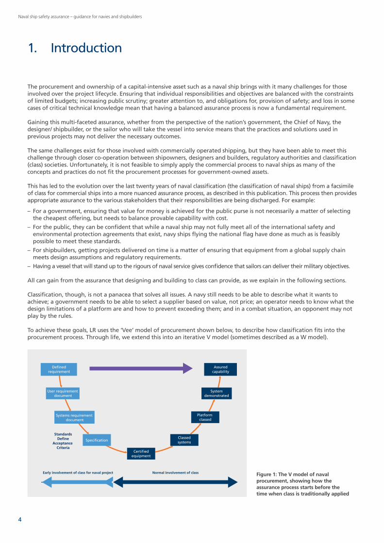
To achieve these goals, LR uses the ‘Vee’ model of procurement shown below, to describe how classification fits into the procurement process. Through life, we extend this into an iterative V model (sometimes described as a W model).
1. Introduction
Definedrequirement
Assuredcapability
User requirement document
Systems requirement document
Systemdemonstrated
Certifiedequipment
Classedsystems
Platform classed
Specification
Early involvement of class for naval project Normal involvement of class
StandardsDefine
Acceptance Criteria
Figure 1: The V model of naval procurement, showing how the assurance process starts before the time when class is traditionally applied
4
Naval ship safety assurance – guidance for navies and shipbuilders
2.1 Naval ship safety assuranceThe term naval ship covers a wide variety of ship types or ‘platforms’ which differ from one navy to another. These include warships, submarines, auxiliary vessels, boats, barges, landing craft and special forces craft.
Assurance can be defined as a freedom from doubt that inspires confidence. Naval ship safety assurance is the process that provides confidence that compliance with a set of key safety requirements and standards is achieved through life, from concept to disposal.
For the purposes of Lloyd’s Register’s naval ship assurance services, safety refers to the safety of the platform, embarked personnel, third parties and property, and the protection of the environment.
Navies identify the level of assurance required for both their ships and the ships’ systems. A process is then put in place to ensure this level is attained. For some navies or naval projects, classification alone will provide a sufficient level of assurance. For others, a greater level of assurance will be required.
Whatever the level of assurance, it must be built in at the earliest stage of the ship’s lifecycle when the stakeholders are defining the exact functions it will need to perform. And it should be maintained through life.
The clear application of naval ship assurance principles (often in the form of a naval assurance framework) should offer up a number of benefits including:
– clear communication of naval performance requirements and definition of benchmarks against best commercial practice
– elimination of the gaps and overlaps between naval and commercial practice thus reducing risk and therefore cost drivers; and
– a reduction in the number of standards documents, thus reducing risk and again cost.
2.2 Alternative standards for naval ship constructionIn the last fifteen years it has become increasingly evident that designers and shipbuilders are employing alternative standards for the construction of modern warships. Previously, warships were constructed and maintained to standards directly developed by the navies themselves but this is changing. There will always be a place for some naval standards, however: capability and some aspects of safety in particular.
These alternative standards are more consistent with commercial ship practices and processes and therefore reap the benefits of a large experience pool as well as the potential to realise cost benefits in the design and construction of naval platforms. Navies are moving towards both commercial off-the-shelf (COTS) and military off-the-shelf (MOTS) solutions.
This move away from using pure military standards is driven by a number of factors including: – legislation – affordability of maintaining specialised naval standards – deteriorating health of naval standards – ship capability – user requirements – accreditation – certification – classification – operating environments – human factors integration – security – through-life support; and – safety case issues.
The selection and application of standards in modern warship design, build and operation to address these factors is of critical importance to the success of a project.
2. Naval ship safety assurance and the role of classification
5www.lr.org/naval

Naval ship safety assurance – guidance for navies and shipbuilders
2.3 The role of classification in assurance
2.3.1 What is classification?Commercial ships over a certain size (usually over 24 metres in length or 500 gross tonnes (gt)) must be ‘classed’. This means they must be certified as in accordance with the requirements of the Classification Rules and Regulations (the Rules) of a recognised classification society, in order to be issued with certificates confirming compliance with the statutory requirements of the flag state (the country in which the vessel is registered). This makes classification a mandatory requirement for a commercial ship to operate.
Classification has long been recognised as a fundamental element of commercial ship safety, and statutory authorities in many countries recognise this. Additionally, these statutory authorities authorise classification societies to undertake surveys and inspections on their behalf by granting them ‘recognised organisation’ (RO) status.
The classification process is used to assure stakeholders that a ship or other marine platform complies with a set of rules or other safety and technical standards that have been shown to be appropriate for its function. This process is achieved by independent audit of the:
– design – equipment and material supply – construction; and – through-life maintenance of the vessel.
Classification as a process is therefore far more than a set of rules. It is an assurance process in its own right that addresses all phases of the platform lifecycle from design to disposal. It is adaptable and it has demonstrated that it can meet the challenges of diverse platforms: for example, wing-in-ground-effect (WIG) craft, very large crude carriers (VLCCs) or very large cruise ships. This makes classification a very powerful tool in the assurance process if used intelligently.
Classification has its origins in the coffee houses of eighteenth century London where surveyors first assigned different ‘classes’ to ships in order for insurers and charters to better understand the risks they were exposed to.
2.3.2 Naval classification and the Lloyd’s Register Rules and Regulations for the Classification of Naval ShipsUnlike commercial shipping, classification of naval and para-military vessels (such as coastguard ships) is an optional process. Its use can be traced back to 18591. The LR Rules and Regulations for the Classification of Naval Ships (the Naval Ship Rules) have been specifically developed to cater for the role that naval ships need to fulfil. They do not cover every structure or piece of equipment but generally cover the systems essential for operation of the ship. The scope of systems and equipment covered by the Naval Ship Rules is greater than the scope of the commercial ship Rules. In commercial shipping, classification is used to reduce risk to a ‘broadly acceptable’ level within an ALARP (As Low As Reasonably Practicable) process in order to meet international safety regulations. The Naval Ship Rules have extensive links to the classification Rules for commercial ships so that an equivalent baseline level of safety is achieved. However, this baseline level is only consistent with peacetime operations when the vessel is undertaking training activities or possibly humanitarian relief.
It should be noted that one of the underlying assumptions for commercial ships is that any incident or damage is contained so that the crew have a safe location to retreat to in order to undertake corrective actions within their capabilities. For a fire scenario this could be the activation of a fixed system (for example, a fire fighting or other emergency system). If these actions do not control the situation, evacuation from the vessel will follow.
For a naval ship, being able to recover from an incident is normally a priority requirement (part of the ‘Float, Fight, Move’ ethos). This may require a different response to an incident and this is one of the fundamental differences between commercial and naval ships.
1 LR was involved in classing vessels for the Portuguese Navy from 1859 when John Scott Russell built the 250 tons steam gunboat Donna Maria Anna to class in the UK for Portugal.
6

Naval ship safety assurance – guidance for navies and shipbuilders
For some commercial ships, however, this naval philosophy is now applied using the SOLAS requirements for ‘Safe Return to Port’. These requirements have similar principles to the Float, Fight, Move ethos: containing the problem, maintaining propulsion and being able to provide limited services for passengers and crew for a short period (three or four days).
For naval ships it is therefore imperative that the scope of classification is closely matched to the intended function and operational requirements of the vessel. Therefore, if the concept of operations (CONOPS) for the vessel has functional requirements above this baseline, then these must be captured during the classification process so that the solution presented by the designer and builder can be assessed against the elevated level of risk. This is done by determining a set of class ‘notations’2 derived from a functional breakdown of the CONOPS statement. As this is the starting point, it requires the naval authority to agree to the scope early in the project lifecycle. Naval classification then does not seek to impose capability on the basis that it provides a safer solution, but seeks to provide assurance to a navy (and to the designer and builder) that the vessel represents an appropriate level of safety when being operated as intended. A comparison of the role of classification for commercial and naval ships is shown in Table 1.
2.3.3 Classification in practiceDuring design and construction of the vessel, classification provides assurance by verifying materials and equipment brought in by the shipbuilder. Through life, periodic surveys are carried out to confirm the material state of the vessel and to assess continued compliance with the Rules. The owner or operator is obliged to advise Lloyd’s Register of any damage or alterations to the vessel that impact on the classification of those systems which are covered.
Commercial ships Naval ships
Role of class Demonstrates that materiel safety is in compliance with international legislation
Demonstrates that materiel safety has been benchmarked against international legislation while recognising the operational role of the vessel and also recognising that the navy may have a higher tolerance of risk in specific situations
Table 1: The role of class for commercial and naval ships
Classification
Rules
Des
ign
appr
aisa
l
Mat
eria
ls
Cons
truc
tion
Surv
ey Process
Scope
Figure 2: The process of naval classification
January 2014
General Informationfor theRules and Regulationsfor the Classificationof Naval Ships
2 Class notations are assigned to a vessel to denote its specific functions and requirements. For example, the notation LSAE denotes life-saving and evacuation arrangements.
7www.lr.org/naval

Naval ship safety assurance – guidance for navies and shipbuilders
The Rules themselves are managed through a well-defined formal process and are approved for application by a Technical Committee comprising members of navies and the defence industry worldwide. This ensures that they are pragmatic, provide an acceptable level of safety and are effective in meeting the expectations of users. The Rules are a live document and are updated regularly to reflect service experience and technical change. In this way they maintain their efficacy over long periods of time.
When we describe classification, we actually mean that we comply with the technical requirements of a particular set of Rules and that this compliance is achieved by the ‘regulatory’ part of the Rules. Hence the reference to the ‘Rules and Regulations’.
These ‘Regulations’ in the Rules and Regulations for the Classification of Naval Ships allow the substitution of other appropriate technical standards, provided that these standards give (at least) an equivalent level of safety. For some vessels, it is possible that the alternative standard could be another set of LR Rules: for example, hovercraft can be classed under the Naval Ship Rules but the technical criteria are found in the Rules and Regulations for the Classification of Special Service Craft. If this approach is used, the Naval Ship Rules have specific notations to indicate the fact.
2.3.4 Assurance is more than just classificationWhile naval ship safety assurance and naval classification are complementary they are not interchangeable. It is sometimes misunderstood that the correct application of naval classification will automatically deliver the level of assurance that navies require for their vessels. This is not always the case.
For some vessels and navies, the scope of classification or certification will fully meet the overall safety assurance requirements. This is most likely with smaller vessels such as boats.
In other cases, a greater level of assurance will be required and additional technical standards will need to be applied. This may be achieved by the navy applying a safety case3 to the platform, to which naval classification can contribute.
Interestingly, in a test exercise, a reverse engineering approach was used to identify the specific hazards addressed by the machinery and electrical sections of the Naval Ship Rules. These were then compared against the hazards identified in the reference safety case for the same systems. While the Rules addressed the majority of hazards, the safety case only identified a minority. This may have implications for safety certification submissions that rely solely on a safety case for justification.
2.4 Naval authoritiesThroughout this guide, we make reference to naval authorities. In the context of classification and safety assurance, a naval authority broadly equates to a statutory authority or flag state in the commercial shipping context.
The naval authority is responsible for ensuring to the Chief of Navy that the vessels he is responsible for are certified to the safety standards or approved codes of practice which are appropriate and relevant to their specific functions.
The naval authority will normally address what are considered key hazards in naval operations, such as: – fire – explosion – escape and evacuation – stability – structures – propulsion and manoeuvring systems.
The naval authority will also be responsible for ensuring that any common requirements that the navy has for design, construction or through-life upkeep are applied. It may also have responsibility for ensuring that third parties that provide certification to the navy are suitably competent in the work that they undertake and that any issues that arise during the delivery of services to individual organisations within the navy are brought to their attention in order that they are properly addressed.
This competence assessment is usually part of the process of appointing third parties as recognised organisations who undertake certification on the authority’s behalf (see 2.5).
3 Defence Standard (Def Stan) 00-56 defines a safety case as being a structured argument, supported by a body of evidence, that provides a compelling, comprehensible and valid case that a system is safe for a given application in a given environment.
8

Naval ship safety assurance – guidance for navies and shipbuilders
2.5 Naval authority delegation to recognised organisationsIn a similar process to that employed by statutory authorities and flag states in commercial shipping, Lloyd’s Register has been granted recognised organisation status by various naval authorities. The powers delegated to LR vary from authority to authority.
2.5.1 Authorisation levelsThere are three authorisation levels: – full authorisation for all activities and issue of certification – partial authorisation with no authorisation to issue certificates – limited authorisation for new construction agreed on a project-by-project basis.
2.5.2 Authorisation activitiesThe authorisation activities that LR may carry out include: – review of operational requirements and certification plan – review of design disclosure and operational guidance – material state verification and survey – issue of certification.
2.5.3 The delegation process Each naval authority issues a formal letter or document of delegation specifying the exact authorisation level and activities that the classification society is allowed to undertake on its behalf. These authorisations are reviewed at regular intervals and can be altered as needed.
As an RO acting on behalf of a naval authority, Lloyd’s Register would expect its activities to be audited to make sure that we are discharging our duties correctly.
Lloyd’s Register treats naval authorities in the same way as flag states. We create specific guidance and instructions for our surveyors when undertaking delegated surveys and survey findings are reported to the naval authority through the naval liaison office. If the surveyor observes any defect or condition that would place the naval authority’s certification in jeopardy, this is advised to them.
LR has a network of naval liaison offices worldwide which act as the main point of contact for each country’s naval authority. In countries where there is no dedicated LR naval liaison office, the UK naval liaison office – based in Nailsea near Bristol – acts as the point of contact.
2.5.4 If no naval authority existsIf no naval authority exists within a particular government, the Naval Ship Rules can be used to assist as they include sections covering each of the key hazard areas (fire, explosives, etc.) While for some specialist areas, LR does not claim to be a subject matter expert (for example, in the area of explosive safety and magazines) we have access to suitable expertise.
If the design does not directly comply with the Rules, its acceptability will be assessed in the same way as if a naval authority did exist, but it will be discussed with the project team and the broader navy to understand and agree the acceptability of any deviation. Deviations will be recorded as part of the delivered classification records.
If LR cannot agree a deviation (for whatever reason), the issue will need to be taken to a more senior level in the navy for them to accept the associated risk.
9www.lr.org/naval

Naval ship safety assurance – guidance for navies and shipbuilders
Lloyd’s Register was approached in the late 1990s by the UK Ministry of Defence (UK MoD) and asked to consider producing a set of Naval Ship Rules to support the building of the new generation of Royal Navy warships and auxiliaries. The UK MoD had identified that progressive restrictions on budgets had led to a loss of some of the ‘in house’ expertise in the naval shipbuilding and technical standards areas. Having identified this, it decided to investigate the process for designing and building commercial vessels and see if this could be used to address the shortfalls. Following this investigation, UK MoD decided to approach Lloyd’s Register and make use of the classification process. This decision was further reinforced by the MoD’s experience with the Royal Fleet Auxiliary Flotilla which was classed with LR under the Rules and Regulations for the Classification of Ships (the first RFA vessel, RFA Burmah, was classed in 1911).
As a result of this approach, LR published the first set of Rules and Regulations for the Classification of Naval Ships in 2000. These Rules and Regulations are not static but are subject to constant review and revision. The full set of rules is reviewed and updated every 12 months with corrigenda and minor amends being issued over the course of the year as necessary.
Today, navies around the world are required not only to deliver high levels of capability and availability from their ships but also to demonstrate that these are delivered in a manner that is as safe as reasonably practical for both human life and the protection of the environment. One method of demonstrating this is to follow the commercial process of independent third party classification wherever this is practical. This also ensures that navies are benchmarking themselves with the current best practice used by commercial ships to meet internationally accepted regulatory requirements for safety and the environment. These requirements do not just apply to vessel construction. They also apply throughout a ship’s life. Many navies have realised the largest costs are those related to keeping their ships at the standard required to deliver the desired capability and expected safety levels. The classification process is predicated on a through-life concept and is therefore eminently suitable for supporting a navy’s needs in this respect.
In addition to these requirements, navies find themselves continually required to procure, operate and maintain their platforms in more cost-efficient ways.
Many governments and navies have looked at the commercial model of ship procurement and maintenance to see if commercial practices can offer cost savings for the through-life costs of their ships. This has challenged traditional naval practices in almost all areas of platform procurement, operation and maintenance.
Traditionally, navies retained large amounts of knowledge on naval ship construction and maintenance within their own standards documentation and personnel. Continued pressures on finances and resources within governments and navies has resulted in difficulties maintaining this knowledge base to reflect current standards and practices.
One of the key solutions to this problem devised in the classification process has been the continued knowledge feedback and updating of the classification Rules to keep them as up to date as possible. This feedback is derived from the hands-on experiences gained by surveyors in working with design, construction and in-service ships. The information gained is not just passed back into the classification Rules but is often used to inform other bodies who publish technical standards on their effectiveness. This feedback loop is one of the greatest assets of the classification process employed by Lloyd’s Register.
3. The background to the Naval Ship Rules
10
Naval ship safety assurance – guidance for navies and shipbuilders
Classification has a long history in safety assurance for the merchant marine and this can be adapted to meet the needs of modern navies and their warships and auxiliaries.
In the merchant marine application, class provides a major source of the prescriptive Rule and Regulation requirements to meet internationally agreed standards. It is a requirement for merchant vessels (over 500 gt) to meet the requirements of a recognised classification society in order to be allowed to proceed to sea and to trade. The application of these prescriptive Rules and Regulations in a naval risk-based safety culture is discussed in section 4.2.
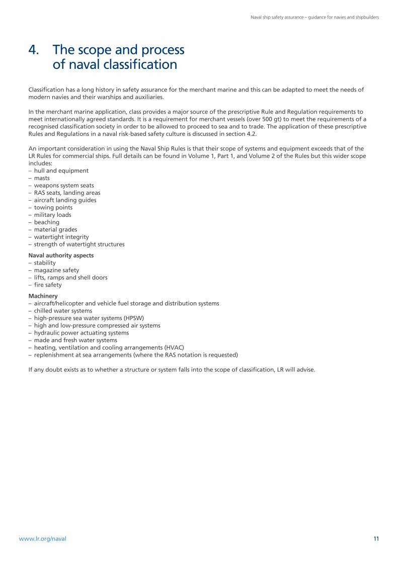
An important consideration in using the Naval Ship Rules is that their scope of systems and equipment exceeds that of the LR Rules for commercial ships. Full details can be found in Volume 1, Part 1, and Volume 2 of the Rules but this wider scope includes: – hull and equipment – masts – weapons system seats – RAS seats, landing areas – aircraft landing guides – towing points – military loads – beaching – material grades – watertight integrity – strength of watertight structures
Naval authority aspects – stability – magazine safety – lifts, ramps and shell doors – fire safety
Machinery – aircraft/helicopter and vehicle fuel storage and distribution systems – chilled water systems – high-pressure sea water systems (HPSW) – high and low-pressure compressed air systems – hydraulic power actuating systems – made and fresh water systems – heating, ventilation and cooling arrangements (HVAC) – replenishment at sea arrangements (where the RAS notation is requested)
If any doubt exists as to whether a structure or system falls into the scope of classification, LR will advise.
4. The scope and process of naval classification
11www.lr.org/naval
Naval ship safety assurance – guidance for navies and shipbuilders
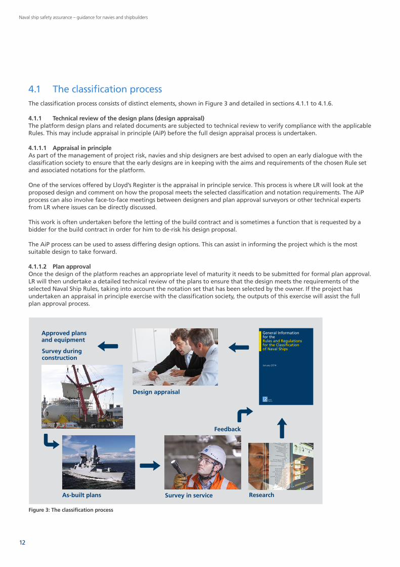
4.1 The classification processThe classification process consists of distinct elements, shown in Figure 3 and detailed in sections 4.1.1 to 4.1.6.
4.1.1 Technical review of the design plans (design appraisal)The platform design plans and related documents are subjected to technical review to verify compliance with the applicable Rules. This may include appraisal in principle (AiP) before the full design appraisal process is undertaken.
4.1.1.1 Appraisal in principleAs part of the management of project risk, navies and ship designers are best advised to open an early dialogue with the classification society to ensure that the early designs are in keeping with the aims and requirements of the chosen Rule set and associated notations for the platform.
One of the services offered by Lloyd’s Register is the appraisal in principle service. This process is where LR will look at the proposed design and comment on how the proposal meets the selected classification and notation requirements. The AiP process can also involve face-to-face meetings between designers and plan approval surveyors or other technical experts from LR where issues can be directly discussed.
This work is often undertaken before the letting of the build contract and is sometimes a function that is requested by a bidder for the build contract in order for him to de-risk his design proposal.
The AiP process can be used to assess differing design options. This can assist in informing the project which is the most suitable design to take forward.
4.1.1.2 Plan approvalOnce the design of the platform reaches an appropriate level of maturity it needs to be submitted for formal plan approval. LR will then undertake a detailed technical review of the plans to ensure that the design meets the requirements of the selected Naval Ship Rules, taking into account the notation set that has been selected by the owner. If the project has undertaken an appraisal in principle exercise with the classification society, the outputs of this exercise will assist the full plan approval process.
Figure 3: The classification process
Rule development
Survey in service Research
Feedback
As-built plans
Approved plans and equipment
January 2014
General Informationfor theRules and Regulationsfor the Classificationof Naval Ships
Design appraisal
Survey during construction
12
Naval ship safety assurance – guidance for navies and shipbuilders
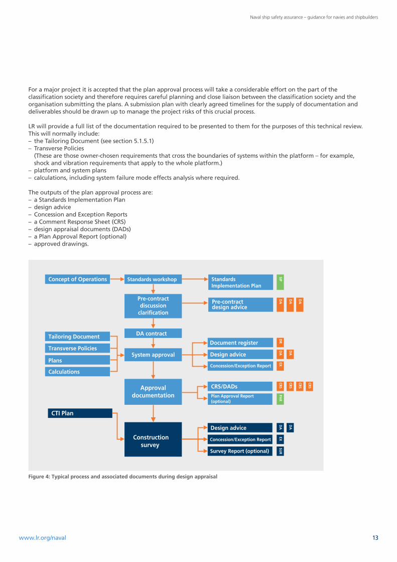
For a major project it is accepted that the plan approval process will take a considerable effort on the part of the classification society and therefore requires careful planning and close liaison between the classification society and the organisation submitting the plans. A submission plan with clearly agreed timelines for the supply of documentation and deliverables should be drawn up to manage the project risks of this crucial process.
LR will provide a full list of the documentation required to be presented to them for the purposes of this technical review. This will normally include: – the Tailoring Document (see section 5.1.5.1) – Transverse Policies (These are those owner-chosen requirements that cross the boundaries of systems within the platform – for example, shock and vibration requirements that apply to the whole platform.)
– platform and system plans – calculations, including system failure mode effects analysis where required.
The outputs of the plan approval process are: – a Standards Implementation Plan – design advice – Concession and Exception Reports – a Comment Response Sheet (CRS) – design appraisal documents (DADs) – a Plan Approval Report (optional) – approved drawings.
SURV Rep (opt)
Concept of Operations Standards workshop
Pre-contractdiscussion
clarification
System approval
Approvaldocumentation
Tailoring Document
Transverse Policies
Plans
Design advice
Survey Report (optional)
CTI Plan
Constructionsurvey
Calculations
Document register
Design advice
Concession/Exception Report
CRS/DADs
Plan Approval Report (optional)
Standards Implementation Plan
Pre-contractdesign advice
DA contract
Concession/Exception Report
Figure 4: Typical process and associated documents during design appraisal
13www.lr.org/naval
Naval ship safety assurance – guidance for navies and shipbuilders
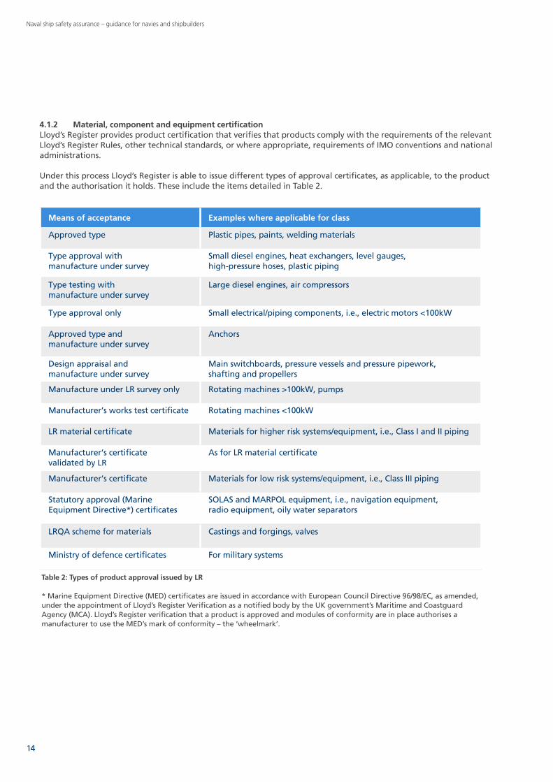
Table 2: Types of product approval issued by LR
* Marine Equipment Directive (MED) certificates are issued in accordance with European Council Directive 96/98/EC, as amended, under the appointment of Lloyd’s Register Verification as a notified body by the UK government’s Maritime and Coastguard Agency (MCA). Lloyd’s Register verification that a product is approved and modules of conformity are in place authorises a manufacturer to use the MED’s mark of conformity – the ‘wheelmark’.
Means of acceptance Examples where applicable for class
Approved type Plastic pipes, paints, welding materials
Type approval with manufacture under survey
Small diesel engines, heat exchangers, level gauges, high-pressure hoses, plastic piping
Type testing with manufacture under survey
Large diesel engines, air compressors
Type approval only Small electrical/piping components, i.e., electric motors <100kW
Approved type and manufacture under survey
Anchors
Design appraisal and manufacture under survey
Main switchboards, pressure vessels and pressure pipework, shafting and propellers
Manufacture under LR survey only Rotating machines >100kW, pumps
Manufacturer’s works test certificate Rotating machines <100kW
LR material certificate Materials for higher risk systems/equipment, i.e., Class I and II piping
Manufacturer’s certificate validated by LR
As for LR material certificate
Manufacturer’s certificate Materials for low risk systems/equipment, i.e., Class III piping
Statutory approval (Marine Equipment Directive*) certificates
SOLAS and MARPOL equipment, i.e., navigation equipment, radio equipment, oily water separators
LRQA scheme for materials Castings and forgings, valves
Ministry of defence certificates For military systems
4.1.2 Material, component and equipment certificationLloyd’s Register provides product certification that verifies that products comply with the requirements of the relevant Lloyd’s Register Rules, other technical standards, or where appropriate, requirements of IMO conventions and national administrations.
Under this process Lloyd’s Register is able to issue different types of approval certificates, as applicable, to the product and the authorisation it holds. These include the items detailed in Table 2.
14
Naval ship safety assurance – guidance for navies and shipbuilders
4.1.3 Construction monitoring (survey during construction)This is attendance during the construction of the vessel at the shipyard(s) by a Lloyd’s Register surveyor(s) to monitor the construction and ensure that it is being carried out in accordance with the classification requirements and to the approved plans. The attending surveyor will also be checking that equipment being supplied to the shipbuilder for the vessel has the correct certification. These certification requirements are detailed in the Certification Matrix.
Surveyors will also attend various production facilities to ensure that equipment and systems covered by class meet the requirements of the applicable Rule and Regulations and the notation set chosen by the navy. The Certification Matrix will be used to determine which premises the classification surveyor will need to attend and the level and type of assessment they will undertake.
A Yard Surveys List is also often part of the Certification Matrix. This is held both by the yard and the surveyor so that all stakeholders can best manage these surveys.
4.1.4 As-built plansThe final as built-plans are passed to Lloyd’s Register for adding to our online fleet management service Class Direct and our records. These plans will reflect the differences between the design plans and the actual vessel as constructed. They are much more user friendly, being a closer representation of the actual ship.
4.1.5 Assignment of classOn successful completion of the previous steps, the shipowner may request the classification society to assign class to the vessel and issue the appropriate classification certificate. The assignment of class is assumed in the LR contract although the owner may opt out if they wish.
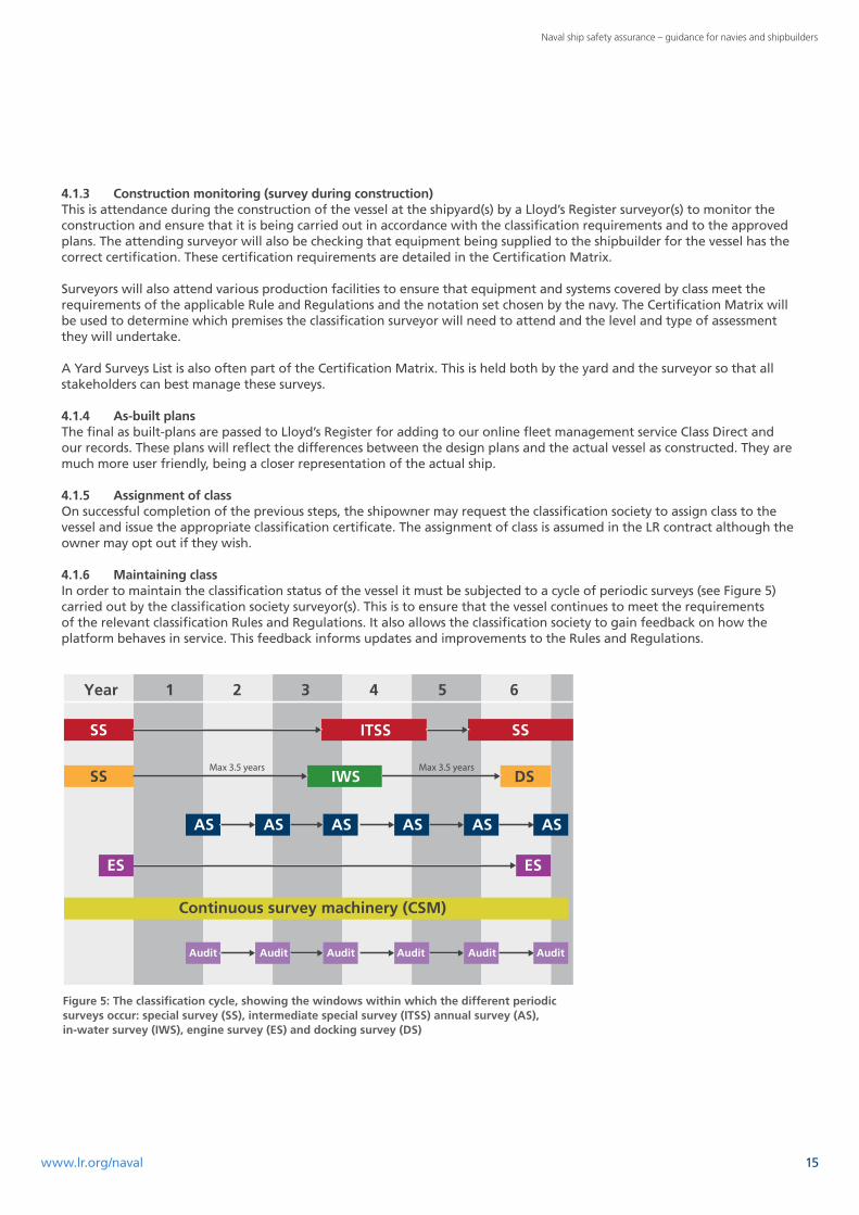
4.1.6 Maintaining classIn order to maintain the classification status of the vessel it must be subjected to a cycle of periodic surveys (see Figure 5) carried out by the classification society surveyor(s). This is to ensure that the vessel continues to meet the requirements of the relevant classification Rules and Regulations. It also allows the classification society to gain feedback on how the platform behaves in service. This feedback informs updates and improvements to the Rules and Regulations.
Year 1 2 3 4 5 6
ITSS
IWS DS
AS
ES ES
AS AS AS AS AS
Audit
Continuous survey machinery (CSM)
Audit Audit Audit Audit Audit
Max 3.5 years Max 3.5 years
Figure 5: The classification cycle, showing the windows within which the different periodic surveys occur: special survey (SS), intermediate special survey (ITSS) annual survey (AS), in-water survey (IWS), engine survey (ES) and docking survey (DS)
15www.lr.org/naval

Naval ship safety assurance – guidance for navies and shipbuilders
4.2 The role of classification in a risk-based safety caseA number of navies employ a risk-based approach to safety assurance using a platform safety case. For navies that do employ this approach, classification can support the safety case, and indeed in some cases can provide 70 or 80% of the required evidence that the ship or system safety case requires.
4.3 Maintaining classification Rules and Regulations The process of classification employed by Lloyd’s Register requires that the Rules and Regulations are continuously reviewed and updated to reflect experience, changing technologies and changes in regulatory requirements. The ongoing process of periodic survey is part of this system of updating the Rules and Regulations and provides first-hand information regarding the performance of both materials and design.
Although Lloyd’s Register reviews and updates its Rules and Regulations every year, the Rules and Regulations which were selected for the build of the vessel will apply throughout the ship’s life. There are very few instances where Rules and Regulations are applied retrospectively. When this does happen, it is usually as a result of a change in legislation (or naval authority requirements).
Regulators
Flag state(MCA)
Ship safety board (NAs)
Key hazardcertification
NA wants visibility of theapplicability and application
of standards chosen
CertificateCertificate
Component
Certificate
Safety management system/through-life management plan
Other risks notadequately dealtwith by standards
(System, operational, etc.)
Safety case
Classification
Technicalstandard
Figure 6: The role of classification in a risk-based safety system
16
Naval ship safety assurance – guidance for navies and shipbuilders
4.4 Existing shipsThe process of classification does not just apply to new construction naval vessels but can be applied to existing ships as well, subject to certain criteria.
Each case will be considered on its own merits and will take account of a number of items such as whether the ship was constructed under survey with LR or another IACS4 classification society. If the vessel was not under survey when constructed it may still be considered for acceptance into class. The age and service record of the ship will also be considered as well as its function and operational environment.
Ships built under survey that have not subsequently been retained in class are also eligible for consideration on a case-by-case basis in a similar manner to ships not constructed under survey.
4.5 The benefits of classificationThe benefits of using Lloyd’s Register as part of the assurance processes of a navy are varied and will have differing priorities for the various stakeholders involved. The following are some of the more well-defined benefits:
– A navy can demonstrate through independent third party verification that either naval or national policy for compliance with international conventions has been achieved.
– If a navy is constrained in maintaining their own technical standards, the experience gained from operation of their vessels is captured for posterity in the classification Rules.
– The costs of naval vessels are not driven by application of naval standards unless fully justified.
– Materials and equipment being procured from a global supply chain (not under direct navy oversight) meet specified standards.
– Classification can be used as a verification criteria with shipbuilders.
– Classification provides a comprehensive Rule set covering all vessels types from aircraft carriers to small patrol boats.
– LR’s naval classification is designed to be flexible and not just to apply prescriptive requirements without justification.
– If Rule requirements are not considered applicable, a well-proven process to deal with non-compliances exists.
– The Naval Ship Rules have input from many navies ensuring that they have a wide baseline of operational experience.
4 The International Association of Classification Societies
17www.lr.org/naval

Naval ship safety assurance – guidance for navies and shipbuilders
As a ship has a lifecycle from concept to disposal, it is logical for this guidance to discuss the input from LR and the classification process against the same timeline. The major phases of this lifecycle (known as the CADMID cycle) are: – Concept phase – Assessment phase – Design phase – Manufacture phase – In-service phase – Disposal phase.
These phases will be familiar to many people involved in naval ship procurement although slight differences in terminology may be used by different organisations.
In some cases, functions can cross the boundaries of the phases. For instance a draft Tailoring Document may be produced during the concept phase but this will be refined through the early parts of the assessment phase.
5.1. Concept phaseThe concept phase begins with recognition of the need for a new ship or system to meet a capability requirement.
This phase is for the initial exploration, fact-finding and planning exercises where technological, strategic and commercial market assessments take place.
It is in this concept phase that Lloyd’s Register can first start to support the project and its development. This function is not directly part of the classification process but is a consultancy function in support of the whole ship safety assurance process.
LR has undertaken this consultancy role for a number of major naval projects, helping to develop key documents describing the ship’s role and operating environment and how the platform is going to meet these requirements. These are sufficiently detailed to provide the project and partners with the information they need to take the project to a successful conclusion. Currently, these documents include the Concept of Employment, Concept of Use, Tailoring Document and the Certification Matrix.
These activities are outside the normal classification cycle, which does not normally start until the design phase. However, this initial phase is critically important to the whole project in ensuring that a solid safety assurance programme is in place one that is in keeping with the requirements for the particular navy or government.
5.1.1 Aims of the concept phaseThe aims of the concept phase should be to:
– frame the functional specification based on the User Requirements Document (URD) that should clearly identify what is expected of the ship
– form a delivery team
– involve industry
– produce Concept of Use (CONUSE) and Concept of Employment (CONEMP) statements
– identify and assess feasible technology and procurement options for further investigation
– select the provisional standards suite for the project including the appropriate classification Rule set and provisional notation set.
– consider human factors integration issues*
– produce the systems Certification Matrix and Tailoring Document*
– identify and resolve trade-offs between user initial capability requirement and feasible and affordable options ensuring the URD reflects these changes*
– initiate a through-life management plan for the platform.*
* These items can form part of the Acceptance Plan or Validation and Verification Plan for the platform
5. The CADMID cycle
18

Naval ship safety assurance – guidance for navies and shipbuilders
Although the concept phase occurs before the primary functions of the classification process, experience has shown that the involvement of Lloyd’s Register in this phase can support the project both in this phase and the subsequent ones. This is achieved by identifying how specific capabilities will be demonstrated through the acquisition process.
The ways that Lloyd’s Register can support a project during the concept phase are examined in more detail in the next sections.
5.1.2 Concept documentsThe two main concept documents are the Concept of Employment and the Concept of Use. These documents have effectively replaced the Concept of Operations document that has previously been used in the naval platform acquisition process
5.1.2.1 Concept of Employment The Concept of Employment (CONEMP) describes how a new capability will be employed and is written primarily to allow the requirements for that capability to be refined before the project is approved to proceed (sometimes referred to as ‘Main Gate’).
The CONEMP is for a specific capability within a range of operations or scenarios that the platform is expected to experience.
The CONEMP provides context to support a developed User Requirement Document and is essential for proper assessment and approval of the project.
5.1.2.2 Concept of UseThe Concept of Use (CONUSE) is a developed CONEMP. This document describes the way in which a capability is to be employed in a range of activities, operations and scenarios.
The CONUSE is designed to support the System Requirements Document. The CONUSE requires regular review and update, especially whenever the requirements or use for the platform change.
5.1.3 Standards selection and managementThe process of standards management for naval ship projects can be challenging and complex but is vital to inform the rest of the process. A standards policy usually exists in all organisations responsible for the design, construction, installation, testing, operation and through-life support of systems (ships).
In order for the standards process to be successful, all stakeholders must be involved in the selection, development and implementation of the standards. The output of this collaboration is usually a Standards or Certification Matrix (see section 5.1.5.2). The management of this process is the responsibility of the delivery team who will be overseeing the project from concept to at least the in-service (utilisation) phase.
If a navy has a mature naval authority their requirements must be identified as part of this process. For those navies without a naval authority then the careful selection of the appropriate class and notations can provide a level of assurance in those specialist areas usually addressed by the naval authorities.
The selection of standards requires careful judgment of their applicability, interfaces and compatibility. A common problem is the selection of contradictory standards: the process of standards management should aim to prevent this from happening.
Principal standards will have been selected in the draft CONEMP document and one of the first functions of the standards management process is to confirm these as a correct viable set of principal standards.
The careful selection of open standards (publicly available standards with known rights of use) can greatly benefit a project in terms of selection of cost-effective system solutions.
The standards that have been selected will be used to develop the Certification Matrix (see section 5.1.5.2).
19www.lr.org/naval

Naval ship safety assurance – guidance for navies and shipbuilders
5.1.3.1 The Naval Ship Code – ANEP-77The Naval Ship Code (NSC) – Allied Naval Engineering Publication-77, an unclassified document published by NATO – now exists for use as part of the standards management process. This document is goal-based and aims to provide:
– safety assurance – demonstrable evidence that naval ships have been benchmarked against statute, providing a sound foundation for a robust safety framework
– capability – protection of military capability and common standards for interoperability, enabling responsible competition between classification societies under the umbrella of an intergovernmental naval body (NATO)
– forum – a framework for navies and classification societies to share ideas and experiences, and reach a common understanding and a world body of knowledge to protect and sustain naval capability.
Most goal-based codes follow a multi-level structure format and Figure 7 shows the approach used in the development of the NSC.
The NSC is accepted by a growing number of navies and naval authorities as providing the goals for safety assurance of their ships and platforms. In fact, a number of naval projects have stated the requirement to use the NSC to meet the required level of safety assurance.
5.1.3.2 Emergency responseClassification can also support a navy in the event of an emergency involving damage to the ship’s structure. Lloyd’s Register operates a Ship Emergency Response Service that can provide structural assessment of a casualty and make recommendations on how best to manage the vessel to avoid further damage or loss of the ship.
5.1.4 Naval ship assurance frameworkExperience gained from a number of warship projects has suggested that a ‘naval ship assurance framework’ benefits projects by providing them with a road map to guide the development of the assurance process. This framework consists of four main elements – guidance documents, the regulatory regime, class Rules and Regulations, and standards. The framework can be thought of as a bookcase, as shown in Figure 8.
Part 1
Part 2
Part 3
Overall objective of the Naval Ship Code
Goal for each chapter
Functional objectives definedto create the regulatory structure
Statements tojustify text
The requirements for eachfunctional objective
Detailed rules and methods for verifying compliance
0 Aim
1 Goal
2 Functional objectives
3 Performance requirements
4 Solutions
5 Justification and guidance
Validation
Verification
GuidanceExplanatoryinformation
Figure 7: The goal-based approach to developing the Naval Ship Code
20

Naval ship safety assurance – guidance for navies and shipbuilders
5.1.4.1 Guidance documents These are the high-level documents that navies use for the overall direction of the procurement process. These will be unique to each navy. They often consist of design guides and tools as well as guidance on how acquisition projects should be managed to meet government and naval governance requirements.
5.1.4.2 The regulatory regimeThe regulatory regime selected will vary from navy to navy and from project to project, but broadly they will usually be based on the requirements of:
– The Naval Ship Code, which is a goal-based safety code and is sponsored by the International Naval Safety Association, an organisation consisting of a number of navies and classification societies working together.
– The navy’s internal naval authority responsible for the regulation of their vessels in such areas as fire, stability, escape and evacuation. If such an authority does not exist within a navy then careful selection of classification Rules and notations can assist.
– The requirements of the International Maritime Organization Conventions (for example, SOLAS).
Figure 8: The framework bookcase
21www.lr.org/naval
Naval ship safety assurance – guidance for navies and shipbuilders
5.1.4.3 Class Rules and RegulationsFor each project, the appropriate classification Rules and Regulations and notation set will be selected. Classification alone provides a number of functions that are designed to provide assurance as to the safety of various sub-systems and the system (ship) as a whole. These functions cover:
– technical review of the design plans and related documentation to verify compliance with the Rules
– on-site surveyor attendance at various manufacturer’s production facilities – the ones that provide key or critical systems, sub-systems or elements (The Certification Matrix will be the guiding document for the level of scrutiny that will be applied and to which systems.)
– attendance by a surveyor at the build yard(s) to ensure that the ship is constructed to meet the design and in accordance with the classification Rules
– assignment of class and a classification certificate for the vessel, subject to the processes having being completed to the required standards
– a cyclic survey regime throughout the life of the vessel to ensure that the ship continues to meet the required standards, including the assessment of any modifications and upgrades applied to the ship through its service life (likely to be 20+ years).
5.1.4.4 StandardsThese may be drawn from many sources and be a mix of military and commercial, national and international. They will be detailed in the Tailoring Document and the Certification Matrix. In order to achieve effective safety assurance, it is absolutely essential that the process of standards selection and management is undertaken very early in the project and is properly resourced. The selection of the correct standards will inform many of the choices in the subsequent phases and the assessment of the level of achievement at each phase.
This process of standards selection and management will differ from project to project and must take account of the size and complexity of the ship.
5.1.5 Tailoring Document and Certification MatrixTwo key outputs of the standards management process are the Tailoring Document and the Certification Matrix. The Certification Matrix will develop significantly as the project progresses through the concept and development phases. It is a vital document for the shipbuilder as it identifies the standards that systems and equipment must meet. This information should inform the procurement process and be an integral part of the contract process.
It is recognised that each project is unique and that the approach must be tailored to suit the vessel, the navy and the regulators.
5.1.5.1 Tailoring DocumentThe Tailoring Document details how a project relates to standards from outside the project itself. With large, complex projects the wide range of such standards means they need to be documented and their impact on the project needs to be managed. In order to do this it is essential for the Tailoring Document to list: – which standards apply – which parts of those standards apply – what options in those standards have been chosen – whether the standards have been deviated from for the project (along with the justification for the deviation) – the hierarchy of the standards, to show which has precedence.
If the standards are being applied for independent assurance (such as classification Rules) then the relevant regulator must be consulted where any deviation from the standard is proposed.
The selection of standards may be directed by a regulator if the project intends (or needs) to obtain approval from that regulator. Figure 9 shows the Tailoring Document and how it details the project standards.
22

Naval ship safety assurance – guidance for navies and shipbuilders
5.1.5.2 Certification MatrixThe purpose of the Certification Matrix is to provide clarity as to what the certification or acceptance criteria are for each system and sub-system.
This document will be crucial to the logistics organisation of the project to ensure that systems and equipment are designed and manufactured to the correct standards and have the appropriate certification.
The level of detail for this document will be dependent on the project complexity and the requirements of the navy.
5.1.6 Selection of engineering system categoriesWithin the Naval Ship Rules, each engineering system is categorised in order to apply a hierarchy of assessment. This is because it is accepted that within the Naval Ship Rules the scope of systems and equipment falling under the scrutiny of class is much greater. With this increase in scope it is clear that it is undesirable for all systems and equipment’s to be subjected to the most rigorous levels of class oversight. The concept of system categories addresses this.
Standards set 2005 Rules and Regulations for the Classification of Naval Ships
Options+100A1 Frigate SA1 AIR ES SDA FDA CM ESA2 +LMC PSMR CCSPOL FIRE
Additional activitiesAssess LV system load tablesReview FO pumping for RA S operationReview walkways to BS5326Review docking calculations
HVAC system
Shafting systemAlternative standards DSTAN 02-304 Shafting DSTAN 02-848 Steel JustificationInterpretations Shaft brake floodingNon-compliance Corrosion protection Justification
Hull structure systemAlternative standards Docking standard JustificationInterpretations Bulkhead floodingNon-compliance Docking Shock design Justification
Tailoring document
Figure 9: The tailoring of standards using the Tailoring Document
23www.lr.org/naval

Naval ship safety assurance – guidance for navies and shipbuilders
As the design for the platform becomes clearer then the application of system categories must be considered. For the purposes of naval classification, ships’ systems can fall into one of three categories: – mobility – ship type – ancillary.
The process of assigning these categories is critically important as under the Naval Ship Rules the requirements for the assessment of these systems and the associated equipment differ. The requirements for each system are set out in the Rules but can be summarised as follows:
Mobility – engineering systems that are installed in order for the ship to proceed on operations and are necessary for: – the watertight and weather-tight integrity of the hull and the spaces within the hull – the safety and reliability of propulsion, steering and other essential auxiliary engineering systems.
Ship type – those engineering systems that are installed in order for the ship to carry out its in-service purpose and are necessary for:
– the operation and functioning of systems and equipment installed for the purposes relating to the ship type excluding the operation and functioning of military systems
– the operation and functioning of emergency machinery and equipment
– permitting command to manoeuvre the vessel within the design envelope.
Ancillary – all engineering systems other than those covered under mobility and ship type, failure of which may compromise the provisions of classification and are necessary for:
– the provision of basic conditions on board for the carriage of stores, fuels, equipment and personnel when the ship is at sea, at anchor or moored in harbour.
The complete selection of system categories cannot be finalised until the development phase has been undertaken and a number of the categories for the various equipment and systems will be defined by the design solutions that are selected.
There are no absolute definitions of which equipment should be categorised dependent on the ship type in the Naval Ship Rules. However, some equipment clearly falls into certain categories (such as equipment and systems associated with the propulsion and steering being categorised under mobility).
There are some systems and equipment that require more careful thought as to their categorisation. One example of this is a chilled water system which provides chilled water to a diesel-electric propulsion plant’s electronic control systems. Because the water system is essential to the propulsion plant’s function, it would be considered under the mobility category.
Careful consideration of the vessel’s role will also be required when selecting equipment and systems falling into the ship type category. If a piece of equipment or system is essential to the function of the ship in performing its primary role (except for military systems outside the scope of LR classification) then this is likely to attract a categorisation of ship type. An example of this may be the aircraft fuelling system on an aircraft carrier where failure of the system would prevent the ship undertaking its primary role.
The ancillary category should be considered if a system or piece of equipment is required to be considered under the Naval Ship Rules for classification but whose failure or degradation would not seriously prevent the vessel from completing its primary role. 5.1.7 Human factors integrationOne of the most important elements in ensuring any system or platform operates safely and efficiently is the human element.
It is critical that human factors are fully considered in the concept phase of a project and that the standards and assessment criteria are carefully selected.
24

Naval ship safety assurance – guidance for navies and shipbuilders
Lloyd’s Register fully appreciates the importance of human factors elements and is closely involved with various international bodies in the development of standards and rules in this area. We are able to provide specialist support and advice on human factors throughout a project with special emphasis on the concept and development phases.
Although some aspects of human factors integration are implicit within classification, many aspects must be undertaken as a consultancy type role. Care must be taken to ensure that these two elements integrate: a clear understanding of what class does and does not require for human factors is essential.
5.2 Assessment phaseThe purpose of this phase is to develop a system that: – meets the user’s agreed requirements – can be produced within the cost and time constraints of the project – can be assessed against the requirements, and – can be operated, supported and retired.
This phase should begin with a sufficiently detailed technical requirement from the concept phase to allow a design solution to be engineered and viable products to be designed for the in-service phase.
The final Systems Requirement Document (SRD) will be an iterative product of the design options considered to meet the URD developed during the concept phase
During this phase where equipment and system selection is taking place it is essential that the requirements defined in the selected technical standards be passed down to contractors and suppliers to ensure that they fully understand the assessment and assurance criteria. These requirements may be a cost driver for the selection of systems and equipment. The Certification Matrix is a key document in this process.
Experience has shown that often these requirements may be known by the prime contractors or suppliers but the information is not passed to sub-contractors. As a result, equipment is supplied without the proper accreditation to meet the technical standards.
It is also in this phase when the first formal stages of the classification process are undertaken (see section 4.1).
5.2.1 Outputs of the assessment phaseThe expected outputs of the assessment phase are:
– an evaluated Systems Requirement Document (SRD)
– a refined standards suite for the project, including firmed up classification rule selection and notation set
– a final Tailoring Document to cover areas where deviation from standard rule sets may be required and set down alternatives along with justifications
– a system design solution including drawings, diagrams, and production plans
– a training requirements package for users
– maintenance requirements, procedures and plans
– a Test and Trial Plan detailing the standards to be met, when the assessments are to take place and who is authorised to undertake the tests (as agreed by stakeholders)
– the passing down of assurance requirements to potential suppliers to ensure that potential equipment and systems will meet the selected assurance criteria, including class requirements.
25www.lr.org/naval
Naval ship safety assurance – guidance for navies and shipbuilders
5.3. Design phase During the design phase, the indicative designs that have been used for the assessment are developed to meet full production requirements.
Therefore, the various requirements of the Certification Matrix and Tailoring Document need to be produced. This involves submission of plans from the designer to LR for formal design appraisal. A list of plans that may be required to be submitted is included in the Appendix on page 34 of this guide. For specific projects, the list of plans will need to be formally agreed. Additional plans or assessments may be required arising from the tailoring agreed.
5.3.1 Outputs of the design phaseThe outputs of the design phase are primarily the design appraisal documents (DADs) that are produced for each system or plan submitted for approval. The DADs identify which plans they relate to and contain any relevant comments that the designer or attending surveyors need to take account of during construction.
If issues are identified with the design, additional correspondence and information will be required to permit the issue of a ‘clean’ DAD – i.e., one that has no further design issues identified. A clean DAD, however, will include items that the attending surveyor will need to confirm: these are indicated by the use of an ‘AQS’ identifier associated with a particular comment.
These comments will form part of the site supervision team’s project management plan and will usually be recorded so that a full audit trail confirming they have been addressed will be available at delivery.
It is not normal practice for individual plans to be ‘marked up’ during Design Appraisal, especially as plans are now normally submitted electronically. Instead, images of any areas of interest are included in responses to the yard and the issues are described in an accompanying Comment Response Sheet. It is then the responsibility of the attending surveyor to ensure that the item is dealt with and changes are included in the as-built drawings delivered with the vessel.
5.4. Manufacture phaseOnce the contract for production of the ship has been awarded, the manufacture phase begins. This involves the production, assembly, integration and testing of the systems that constitute the ship (the overall ‘system’).
In order to achieve the levels of assurance required by navies it is essential that the correct levels of assessment are applied to all the systems.
These levels will have been determined and documented by the production of the equipment Certification Matrix and Tailoring Documents. These documents will have defined the assessment standards for the individual equipment or sub-systems as well as the ship overall.
At this point the second part of the classification process takes place (see section 4.1.3), not only at the construction yard(s) but also at the many suppliers’ premises where Lloyd’s Register surveyors will be surveying equipment and systems (or sub-systems) to ensure they meet the classification requirements. The surveyors may also survey the equipment and systems against other standards that have been defined in the Tailoring Document and the Certification Matrix. If this extra survey work is required, the Lloyd’s Register project manager will advise the attending surveyor of the extended requirements.
During construction of the ship, various types of inspection and survey will be required. These will be undertaken by a number of organisations (Lloyd’s Register, the shipowner’s inspectors and the naval authority’s (or on some occasions flag state’s) surveyors). In many of these inspections (either formal or informal ones) more than one inspecting ‘authority’ will wish to be present. It is therefore essential that the comprehensive Test and Trial Plan produced in the assessment phase (see section 5.2.1) is adhered to.
5.4.1 Outputs of the manufacture phaseThe outputs of the manufacture phase are:
– the acquisition of resources, materials and components to meet the production goals of the project, including meeting classification requirements where appropriate
– assembly of the ship in line with the production schedule and the assessment and test schedules, including classification requirements,
26
Naval ship safety assurance – guidance for navies and shipbuilders
– implementation of the scheduled training package
– maintenance of equipment as it is fitted to the platform and before the ship is accepted by the user, and
– compilation of the Inventory of Hazardous Materials (IHM) (also known as a Green Passport) – see section 5.6.
5.5 In-service phaseThe in-service phase (also referred to as the utilisation phase) forms the greatest part of the ship’s life. In this phase, compliance with the standards that have been selected through the previous phases needs to be maintained. Designing, building and delivering a vessel to meet the levels of safety assurance defined in the concept phase is essential but this is just the start of the through-life process of safety assurance.
In order to continue the level of safety assurance for the ship’s operators achieved at delivery, the process of classification must continue.
5.5.1 Through-life classification surveysThrough the ship’s life, periodic surveys are undertaken by classification society surveyors. The level and complexity of these surveys varies according to the ship’s position in the ‘classification cycle’ (currently six years for naval vessels) and the type and age of the vessel. There are specific additional requirements for vessels such as naval auxiliary tankers. The different types of periodic survey are detailed in sections 5.5.1.1 to 5.5.1.10.
5.5.1.1 Special survey (SS)The classification cycle commences on completion of the special survey (SS). This commencement date is referred to as the assigned date and the timings of the surveys that take place during the cycle are based on it. Special Surveys are usually carried out during a refit and dry docking period. They are due at six-yearly intervals and can be commenced up to 12 months before the due date. The SS should coincide with a docking survey (see 5.5.1.6).
5.5.1.2 Annual survey (AS)Annual surveys (AS) are scheduled to be completed on the anniversary of the assigned date (although they can be carried out up to three months before or after this date). The AS is a visit to the ship by the surveyor to ensure that the ship is being maintained to expected standards, especially in the safety and watertight integrity areas, and to check for any configuration changes that have not been notified to LR.
5.5.1.3 Intermediate survey (ITSS)An ITSS may be undertaken in lieu of the 3rd or 4th annual survey. This choice is at the discretion of the navy, with advice from LR. The ITSS is an extended annual survey which includes checks of electrical systems (in the operational condition).
5.5.1.4 In-water survey (IWS) (subject to the ship having a *IWS notation)An IWS is in lieu of a Docking Survey and is for the inspection of the underwater hull and appendages.
It is carried out by LR-approved diving contractors with an attending surveyor assessing the video captured by the divers. It must be carried out in clear water for good visibility and in an area safe for diving operations.
The IWS must be undertaken not more than 3.5 years since the completion of the previous docking survey. The next docking survey must be started not later than 3.5 years from the date of the completion of the IWS.
5.5.1.5 Engine survey (ES)An ES is a complete survey of the machinery, electrical systems and equipment covered in the scope of class. This will include sea-openings and shafts and is best conducted in conjunction with a dry docking.
5.5.1.6 Docking survey (DS)This is a survey of the hull and appendages with the vessel in dry dock. The interval between DS (or IWS, if allowed) must not exceed 3.5 years (since the classification cycle is six years, a 3.5-year interval between DS and IWS would make the interval between IWS and the start of the next cycle just 2.5 years). Note that if a ship is dry docked for any other purpose (defect or damage repair, for example) the Lloyd’s Register surveyor must be called to attend. The surveyor may or may not credit the visit as a docking survey subject to what they observe and how this might affect the survey cycle.
27www.lr.org/naval

Naval ship safety assurance – guidance for navies and shipbuilders
5.5.1.7 Continuous survey hull (CSH) and continuous survey machinery (CSM)As an alternative to SS and ES, the owner may choose to employ CSH and/or CSM respectively.
CSH is where the hull and associated parts of the ship (tanks, etc.) are inspected on a rolling basis (but not exceeding an elapsed time equivalent to the six-year classification cycle). This gives the navy the option to de-risk and reduce the survey time required at the major docking periods. The selection of CSH does not remove the requirement to dock the vessel for a detailed inspection of the hull.
CSM is a similar system for the machinery items covered by the scope of class. This system allows for the accreditation of items of machinery during a classification cycle. This means that survey inspections can be effectively combined with major maintenance work, reducing the need to open up equipment purely for inspection by a surveyor during an engine survey. As with CSH, the survey periods for equipment cannot normally exceed the classification cycle period. However, if major items of equipment do not accrue sufficient hours to warrant major opening up for service, LR may give special dispensation to extend the period. This requires prior agreement with LR.
The application of CSH and CSM (CSM, particularly) can offer a navy the ability to reduce through-life costs by undertaking surveys when equipment is already opened for maintenance. Where CSM is combined with the Machinery Planned Maintenance Scheme (MPMS)5, the option for approved ship’s staff to undertake some survey work exists.
5.5.1.8 Defect and damage surveys / visitsAs well as being subject to periodic surveys, the likelihood is that a ship will suffer from defects and damage during its life. When such events happen, and if the results of the damage or defect affect the classification of the ship, then the classification society must be engaged to undertake an assessment of the situation and offer advice on repair to ensure that the requirements of classification are maintained for the vessel. On completion of the repair, the classification society will need to survey the work in order to ascertain that the ship continues to meet the requirements of classification. This requirement for navies to engage with Lloyd’s Register in the repair and maintenance of equipment covered by class is a new concept for many navies: they must ensure that processes are in place to ensure the requirement is met.
In addition to maintaining the class status of the ship, defect information can be used by the classification society in conjunction with other knowledge to ascertain if some re-design of the equipment or change to the class Rules is required. Defect information is not released to third parties without the express approval of the navy.
5.5.1.9 Naval authority / flag state surveysA number of countries require that naval vessels hold various safety certificates in order to demonstrate that they meet the standards required of the naval authorities. Typically the areas covered by such certificates include: – structures – stability (including watertight integrity) – escape and evacuation – fire safety – explosive safety – propulsion and manoeuvring.
Naval authorities do not always have the resources to undertake all aspects of the work involved with this certification and delegate some or all of the work to organisations such as Lloyd’s Register. See section 2.5 for more information on this role.
5.5.1.10 Alterations and additionsA modern naval platform is expected to have a service life of at least 25 years (and experience indicates the service life is often more like 35 to 40 years). Clearly, during such a length of service (either under the original owner or subsequent owners) the ship is likely to undergo changes in system configurations or equipment.
Changes to a ship and/or its systems may be minor or major – for example, a complete change of role.
5 MPMS is a planned maintenance scheme approved by LR which allows chief engineers to undertake the examination of selected machinery items
28

Naval ship safety assurance – guidance for navies and shipbuilders
If a navy wants the ship to continue to meet the design intent and retain the levels of safety that are delivered by the implementation of classification, it is essential that any alteration or addition be assessed for impact on the ship’s classification certification (as well as impact on the naval authority certification).
For major or significant changes to the ship that impact on the classification status, Lloyd’s Register will assess the proposed changes against the classification Rules and Regulations that apply to the vessel in the same manner as the original design appraisal. For more minor changes, it may be appropriate for an attending surveyor to assess the changes and give approval for them on board.
In respect of the impact on naval authority certification, the navy must approach the authority itself, although Lloyd’s Register may be able to assist with the assessment of the changes, taking account of the level and type of delegation from the naval authority.
As part of the through-life management of the ship, the changes that are instigated under the In-service phase must be considered in updating the ship’s Inventory of Hazardous Materials (IHM) – see section 5.6.
5.6 Disposal phaseIn the modern, environmentally conscious world, the disposal of any ship or craft must be carefully considered from the platform’s concept and must include the changes that occur during the life of the vessel.
5.6.1 Inventory of Hazardous Materials (IHM)The IHM (also known as a Green Passport) is an inventory of materials present in a ship’s structure, systems and equipment that may be hazardous to health and the environment. This will be a key requirement of the Hong Kong International Convention for the Safe and Environmentally Sound Recycling of Ships (2009) – the Ship Recycling Convention6.
Before the ship is recycled, details of additional hazards in stores and wastes are added, and the document can then be used to help the recycling yard formulate a safer and more environmentally sound plan for decommissioning the ship. As well as being an invaluable tool for the ship recycling facilities, the IHM also helps to raise staff awareness of the materials on board a ship that may require special handling.
A ship’s IHM is maintained throughout its life. Therefore it is essential that it is incorporated into the ship’s through-life management plan.
The compilation of the IHM must be started no later than the manufacture phase. The shipbuilder is in the best position to collate the data for the completion of this document, but Lloyd’s Register can assist in this process. We provide an IHM (Green Passport) approval and verification service for both newbuilds and existing ships.
6 The Ship Recycling Convention is not yet in force. To find out its ratification status, visit www.imo.org/About/Conventions/StatusOfConventions
29www.lr.org/naval
Naval ship safety assurance – guidance for navies and shipbuilders
The process of naval ship safety assurance covers every phase of a platform’s life. If the greatest benefit to safety and cost is going to be achieved, then this assurance process must be an integral part of the through-life management plan.
The use of classification as a means to demonstrate compliance to an accepted standard for safety assurance of naval vessels is now well-established. For continued assurance about the material state of such complex ships, classification is continued throughout the ship’s life.
Although classification contributes to a naval ship’s safety assurance it is unlikely to cover all safety perspectives. Other areas such as munitions, combat systems and air operations are outside the scope of class and would be expected to be managed by the processes defined by a naval authority. They may require the application of military standards or a safety case. Interfaces between these aspects and class can, and should, be managed as part of the wider assurance activities.
6. Conclusion
30

Naval ship safety assurance – guidance for navies and shipbuilders
The following information and plans must be submitted in triplicate. One approved copy of the plans is returned to the client, one copy is issued to the attending surveyor(s) and one is retained in the office for reference.
Structure
The following plans and information are to be provided:
– midship sections
– profile and decks
– shell expansion
– structural continuity plan showing shadow areas of openings, longitudinally effective material and primary structural continuity material
– oiltight and watertight bulkheads
– deep tank bulkheads – air/overflow heights to be provided
– double bottom construction
– pillars and girders – calculation of pillar loads to be provided
– aft end construction
– fore end construction
– engine room construction
– engine girders and engine seats – details of engines to be provided
– storing routes
– deckhouses and superstructures
– propulsion pod supporting structure arrangements
– supports for masts, cranes, etc. – reaction loads to be supplied
– bilge keel
– anchors and cables
– window location plan
– external door location plan
– access hatches location plan
– watertight door location plan
– loading manuals and stability information booklets, preliminary and final (where applicable) and loading instrument (LI)
– scheme of corrosion control (where applicable) including location of anodes, method of attachment, details of cathodic protection system
– welding schedule
– hull penetration plans including scuppers, sea connections, overboard discharges, arrangements and fittings
– support structure for masts, derrick posts, cranes, RAS points, weapons handling/stowage or machinery lifting point and large items of equipment
– bilge keels showing material grades, welded connections and detail design
– flight deck arrangement and structure.
Supporting information – general arrangement, hull lines plan and body plan
– lightship distribution, still water bending moment envelope
– equipment numeral calculation
– damage waterlines and tank overflow positions
– loading from aircraft
– loading from machinery/cranes/cargo access gear, etc.
– forces resulting from cargo securing arrangements
– towing and mooring arrangements, including forces from towing arrangements (breaking strength of ropes).
Appendix – list of plans required for naval classification
31www.lr.org/naval
Naval ship safety assurance – guidance for navies and shipbuilders
Submission of direct calculationsIn cases where direct calculations have been carried out, the following supporting information should be submitted as applicable:
– reference to the direct calculation procedure and technical program used
– a description of the structural modelling
– a summary of analysis parameters including properties and boundary conditions
– details of the loading conditions and the means of applying loads
– a comprehensive summary of calculation results (sample calculations should be submitted where appropriate).
In general, submission of large volumes of input and output data associated with such programs as finite element analysis will not be necessary.
Component certification
The structural design appraisal is based on the assumption that windows, sidelights, weather and watertight doors, access hatches and other ancillary components of this type are to comply with a recognised national or international standard or are to be LR Type Approved for the particular application. Where these components are of a unique, novel or original design they will be subject to individual appraisal and will attract additional fees.
Engineering systems
– main data of propulsion plant
– main data of Genset-diesel engines
– propulsion shafting (if applicable)
– stern tube seal (if applicable)
– steering gear arrangement
– arrangements of air pipes and closing devices for all tanks and enclosed spaces
– sounding arrangements for all tanks, enclosed spaces and cargo holds
– arrangements of level alarms fitted in tanks, cargo holds, machinery spaces, pump rooms and any other spaces
– arrangement of any cross flooding or heeling tank systems
– bilge drainage arrangements for all compartments which are to include details of location, number and capacity of pumping units on bilge service
– ballast filling and drainage arrangements
– oil fuel filling, transfer, relief and spill/drainage arrangements
– tank overflow arrangements
– details verifying compliance with the sizing of air pipes Rules
– arrangement of oil fuel piping in connection with oil burning installations and oil fired galleys
– arrangement of boiler feed system
– arrangement of compressed air systems for main and auxiliary services.
– arrangement of lubricating oil systems
– arrangement of flammable liquids used for power transmission, control and heating systems
– hydraulic systems
– arrangements of cooling water systems for main and auxiliary services
– oil fuel settling service and other oil fuel tanks not forming part of the ship’s structure
– arrangement and dimensions of all steam pipes where the design pressure or temperature exceeds 16,0 bar (kgf/cm2) or 300°C, respectively, and the outside diameter exceeds 76,1 mm, with details of flanges, bolts and weld attachments, and particulars of the material of pipes, flanges, bolts and electrodes.
32
Naval ship safety assurance – guidance for navies and shipbuilders
Ship type piping systems – piping systems for refuelling helicopters and vehicles
– HVAC system
– made water system
– chilled water system.
The following plans and particulars are to be submitted for approval:
– description of fuel with statement of minimum flash point (closed cup test)
– arrangement of fuel storage and piping
– storage tanks not forming part of the ship’s structure
– arrangements for drainage, ventilation and sounding of spaces adjacent to storage tanks where the flash point is less than 60º C
– details of pumping units
– arrangements for testing and increasing the flash point of low flash fuel from aircraft/helicopters for transfer into the ship’s storage system
– arrangements for gas analysing arrangements required
– arrangements for stripping water from storage tanks
– arrangements for emergency cross connections between aircraft/helicopter and ship’s fuel systems.
Gas turbines (where not being submitted directly by the manufacturer)The following plans are to be submitted for consideration:
– casings, intercoolers and heat exchangers
– compressor and gas generator
– combustion chambers, in rotating components
– control engineering systems
– cooling and sealing air arrangements for compressor and gas generator
– components: schematic only
– cooling water system: schematic only, where applicable
– fuel systems: schematic only
– gas turbine unit acoustic enclosure, if applicable, including ventilation and drainage systems: schematic only.
– inlet and exhaust ducting arrangement
– lubricating oil systems: schematic only
– nozzles, blades and blade attachments
– oil fuel systems: schematic only
– power turbine components
– rotors, bearings and couplings
– sectional assembly
– securing arrangement, including details of resilient mounts, where applicable
– starting system: schematic only.
The following information and calculations, where applicable, are to be submitted:
Operational requirements: – proposed field of application and operational limitations
– power/speed operational envelope
– calculations and information for short-term high power operation
– operation and maintenance manuals including the declared lives of critical components and overhaul schedules recommended by the manufacturer
– calculations of the critical speeds of blade and rotor vibration, giving full details of the basic assumptions
33www.lr.org/naval
Naval ship safety assurance – guidance for navies and shipbuilders
– analysis of the effect of rotor blade release together with details of operating experience
– high-temperature characteristics of the materials, including (at working temperatures) the associated creep rate and rupture strength for the designed service life, fatigue strength, corrosion resistance and scaling properties.
Material requirements: – particulars of heat treatment, including stress relief
– material specifications covering the listed components together with details of any surface treatments, non-destructive testing and hydraulic tests
– the most onerous pressures and temperatures to which each component may be subjected – to be indicated on plans or provided as part of the design specification
– calculations of the steady state stresses, including the effect of stress raisers, etc., in the compressor and turbine rotors and blades at the maximum speed and temperature in service (such calculations are to indicate the designed service life and be accompanied, where possible, by test results substantiating the limiting criteria)
– details of calculations and tests to establish the service life of other stressed or safety critical components, including bearings, seals, couplings and gearing (calculations and tests are to take account of all relevant environmental factors including the particular type of service and fuel intended to be used).
Mounting requirements: – securing arrangements, including details of resilient mounts
– calculations concerning the amplitude and frequency of vibration associated with resilient type mountings.
Electrical and control engineering – single line diagrams of main, emergency and (where applicable to ship type) transitional power supply and distribution systems
– cable schedule showing insulation type, conductor sizes and configurations for main, emergency and transitional power supply and distribution systems
– schedule of main, emergency and transitional operating loads estimated for the normal anticipated operating modes of the vessel
– general arrangement plan of the ship showing the location of major items of electrical equipment
– general arrangement plan of the ship showing hazardous zones and spaces (where applicable to ship type)
– arrangement plans of main and emergency switchboards and section board
– a schedule of electrical equipment located in hazardous zones and spaces (where applicable to ship type)
– typical single line diagrams and arrangement plans of electrically-operated fire, crew and passenger, and ship emergency safety systems (as applicable to ship type)
– general arrangement, description and location of machinery and associated equipment control stations
– list of monitored points for control, alarm and safety systems
– list of control points for control, alarm and safety systems
– list of alarm points for control, alarm and safety systems
– control, alarm and safety systems test schedules for sea trials including methods of testing and test facilities provided
– test schedule which is to include the method of testing and test facilities which are provided for the general emergency alarm system and the public address system.
Failure mode and effect analysis for the following systems – Gas Turbine Vol. 2, Pt 2, Ch 2, 2.1.4
– Systems integration Vol. 2, Pt 9, Ch 1, 2.12.5
– ICC notation Vol. 2, Pt 9, Ch 1, 5.1.2
– Electrical Generation Vol. 2, Pt 10, Ch 1, 2.10.16
– SMR Vol. 3, Pt 1, Ch 5, 1.2.3.
34
Naval ship safety assurance – guidance for navies and shipbuilders
*IWS (in-water survey) notation
Plans and information covering the following items are to be submitted:
– details showing how rudder pintle and bush clearances (or equivalent) are to be measured and how the security of the pintles in their sockets are to be verified with the vessel afloat
– details showing how stern bush clearances are to be measured with the vessel afloat
– details of high-resistance paint, for information only.
Extreme strength assessment (ESA 1)
The following assessments are to be submitted:
– extreme hull girder strength considered at a minimum of three longitudinal locations
– capability assessed using elastic analysis, limiting stress criteria and buckling factors of safety.
Residual strength assessment (RSA 2)
It is to be demonstrated that the residual hull girder strength after the ship has sustained structural damage meets the requirements of a specified performance level with calculations performed using elasto-plastic type analysis. A detailed calculation report is to be submitted for a review by LR.
Fatigue design assessment (FDA2) and construction monitoring (CM)
In the process of plan approval and from fatigue design assessment and structural design assessment, certain critical locations may be identified which require special attention, within the bounds identified by the simplified fatigue procedure in the ShipRight guidance manual. Plans and records of production are to be submitted in accordance with the ShipRight construction monitoring procedures associated with the notation CM aligned with the requirements in the ShipRight guidance manual. FDA calculations are to be carried out in accordance with the appropriate ShipRight procedures with prior approval from LR and submitted for LR review.
Manoeuvring assessment (LMA)
Information required for assessment:
Ship data, where applicable: – length overall
– length between perpendiculars (Lpp)
– moulded breadth
– draught at forward perpendicular
– draught at after perpendicular
– block coefficient
– waterplane area coefficient
– distance of LCG from amidships (positive fwd)
– height of VCG above baseline
– cross-sectional area of bulbous bow, if applicable, at the forward perpendicular below the load waterline
– wetted area of appendages, excluding rudder and propeller
– transverse metacentric height above baseline
– extreme height of the ship structure above baseline.
35www.lr.org/naval

Naval ship safety assurance – guidance for navies and shipbuilders
Propeller data: – number of propellers and direction of rotation
– athwartship position of propellers
– height from baseline, to propeller axis
– longitudinal distance of propeller disc from amidships
– type of propellers (e.g. fixed or controllable pitch, ducted)
– if ducted, type of duct (e.g. accelerating/decelerating) and designation (e.g. NSMB 19A/37 or special type)
– propeller diameter
– mean pitch for fixed pitch propellers
– design pitch and range of pitch for controllable pitch propellers
– number of blades
– developed blade area ratio.
Rudder data: – number of rudders and type
– if active type, rudder characteristics (e.g. rotating cylinder, variable fin, flap length, tail angle)
– lateral underwater projected area of both rudder and horn, where applicable
– mean height of rudder, HR
– longitudinal distance of rudder’s leading edge from amidships
– maximum rudder angle
– minimum time taken to put rudder over from 35 degrees on either side to 30º on the other side.
Propulsion data: – propulsion type (e.g. gas turbine, electric, steam, diesel)
– steady-state developed shaft torque or ship’s speed versus propeller RPM/pitch at each telegraph or combinator setting as identified on the bridge. Times for effecting changes in engine telegraph settings for both normal and emergency conditions
– critical or barred RPM ranges
– main engine stalling revs, if applicable.
Transverse thruster data, if applicable: – type of thruster (e.g. tunnel, Gill)
– longitudinal distance of thruster axis from amidships
– thruster propeller characteristics, viz: number of blades, diameter and pitch
– power at MCR
– time delay to achieve full thruster RPM
– time delay to achieve full reverse RPM/pitch
– predicted thrust versus RPM/pitch curve in clear deep water
– thruster tunnel diameter and height of its centre above the keel
– details of hull profile in the vicinity of thruster tunnel.
Side fins: – lateral fin area
– height of fin, HF
– longitudinal position of the fin, XF, from amidships (positive fwd)
– lateral position of the fin, YF, from the centreline.
36
Naval ship safety assurance – guidance for navies and shipbuilders
Wind parameters: – lateral projected area above waterline
– transverse projected area above waterline
– lateral projected area of the superstructure
– sum of the lengths forming the perimeter of the lateral projection of the ship, excluding waterline
– distance from the FP to the centroid of the lateral projected area.
Ship performance data: – ship design speed
– propeller RPM at ship design speed
– power and percentage MCR to which ship speed and RPM apply
– draught conditions applicable to powering condition
– sea-state applicable to powering condition
– RPM margin on propeller in the case of a new ship.
Plans: – a general arrangement plan of the ship
– a lines plan
– forward and after bridge blind zones with dimensions specified.
Manoeuvring information: – wheelhouse poster and manoeuvring booklet.
Replenishment at Sea – RAS (BV) (NT)
Design statementA design statement of the RAS systems that details the capability and functionality under defined operating and emergency conditions. It is to be agreed between the designers and owners/ operators and is to include as applicable:
– required class notations
– details of intended supply ships
– description of each RAS operation and combination of equipment required
– plans showing each proposed combination of equipment, fully rigged
– details of solids that may be received (maximum size and weight together with UN hazard category if applicable)
– details of liquids that may be received (including flash point of oils and transfer rates)
– details of the range of sea and environmental conditions under which each RAS operation may be undertaken
– interoperability capability
– manning requirements
– details of arrangements for RAS operations in darkness.
Engineering and safety justification An engineering and safety justification for the RAS systems stating the design standards and assumptions and providing technical evidence. The justification is to:
– state all design standards used for the design, manufacture, installation and testing of RAS systems and equipment
– provide details of all RAS equipment and compatibility of different items of equipment
– provide evidence that all RAS operations (equipment and combinations) at each RAS station, as identified in the design statement, can be carried out safely and in accordance with classification and equipment manufacturer’s requirements
– identify safe equipment configurations
37www.lr.org/naval

Naval ship safety assurance – guidance for navies and shipbuilders
– provide calculations that demonstrate that the structural loading is in accordance with Rule requirements
– provide calculations that demonstrate that equipment loads are in accordance with manufacturer’s specified limits
– provide evidence that sufficient control, monitoring and communication facilities are provided to conduct RAS operations safely and efficiently
– examine the dynamic behaviour (e.g., roll period, steering response, tendency to yaw, etc.) of all the supplying ships identified to conduct RAS operations and draw up operational limits that define when RAS operations are not to be conducted between ships when this will result in possible dangerous hull interactions (Limits are to be defined in terms of lateral separation between vessels, wind force, sea conditions (height, swell and direction) and environmental conditions (visibility).)
– examine the effect of environmental conditions (e.g., sea state, water depth, visibility, wind strength, etc.) on the proposed RAS operations and define limiting conditions and limiting environmental conditions for each RAS operation
– address the specific needs of emergency breakaway and demonstrate that such a procedure can be undertaken with all RAS equipment configurations at each RAS station
– provide evidence that the ship internal, ship-to-ship and ship-to-helicopter communications systems will allow safe and efficient communications and RAS operations (The communications equipment and systems provided are to take into account the design of the ship and intended method of operation. Redundancy is also to be considered.)
– provide evidence that each system is designed to minimise the risks associated with handling the particular cargo (e.g., static electricity with aviation fuel).
– include copies of any standards that are not in the public domain (e.g., ATP 16 (latest version) covering NATO Replenishment at Sea).
General arrangement planA general arrangement plan of the ship showing the following information:
– position of each RAS station, with identifiable reference to the engineering and safety justification and design statement
– the tasks to be carried out at each RAS station
– position of observation and control positions
– arcs of fields of view and operation from each of the observation and control positions and RAS stations
– structural plans
– fluid transfer plans and particulars (Plans are to be in diagrammatic form showing filling arrangements from the filling connection to filling trunks (where installed) and subsequently to each storage tank and are to include a statement of the minimum flash point (closed cup test) and the maximum transfer/filling rates.)
– details of equipment identified for RAS operations, including design and installation loads on the equipment together with details of securing and holding down arrangements
– details of the access required for maintenance and to operate the equipment.
Operating manualsOperating manuals are to be submitted for information and provided on board. The manuals are to include the following information:
– particulars and a description of each RAS system
– operating and maintenance instructions for all equipment
– matrix of safe combinations of equipment and details of permitted load that may be carried by each combination
– test procedures for each system
– details of valve and pipe configurations when transferring fluids
– details of arrangements for transfer of solids and personnel
– details of night operations
– testing and trials procedures – a schedule of testing and trials to demonstrate that systems are capable of operating as described in the design statement
– securing arrangements
– details of the connections to the hull of vehicle securing arrangements are to be submitted for approval.
38
Naval ship safety assurance – guidance for navies and shipbuilders
Lifting appliances – LA (N), CL, CR, PL
The following plans and calculations are to be submitted for approval:
Crane systems – calculations clearly indicating the basis of design, operating criteria, rated capacities, weights and centres of gravity of the crane parts, and relevant national standards
– scantling plans of all main structural items comprising the crane, including the jib, tower, platform, gantry, bogies, slewing ring, pedestals, rails and stowage arrangements (Note that pedestals and rails permanently attached to the vessel are classification items if the ship is classed with LR.)
– details of sheaves, axles, pivot pins, wheels, spreader beams, slewing ring, slewing ring bolts, and similar items
– details of blocks, chains, shackles, hooks and other loose gear, indicating material, safe working load (SWL), proof loads (PL) and the standard to which they have been manufactured
– the size, construction, finish and certified breaking loads of steel wire ropes
– the material specification for steels to be used in the crane and pedestal construction
– the service category together with all relevant design criteria.
Lifts and rampsStructural aspectsThe following plans are to be submitted for approval:
– details of mast houses or other supports for the masts, derrick posts or crane pedestals, together with details of the attachments to the hull structure, and details of any reinforcement or additional supporting material fitted to the hull structure in way of the mast, derrick post or crane pedestal
– all main structural plans
– details of sheaves and sheave supports
– calculations clearly indicating the ratings, vehicle loads, wheel centres, tyre prints, working range and angles, design specification, weights and centres of gravity of the component parts
– particulars of hydraulic rams and operating system, if fitted
– reeving arrangements
– the size, construction, finish and certified breaking loads of ropes and chains
– the material specification for steels to be used in the construction
– stowage arrangements.
– mechanical, electrical and control aspects
– diagrammatic plan of hydraulic or pneumatic systems (where fitted)
– plans of winch gearing, shafts, clutches, brakes, coupling bolts, welded drums, and similar items and their materials and stresses
– plans of circuit diagram of electrical system, showing load currents and ratings of all electrical equipment, types and sizes of cables, rating type and make of all protecting devices
– arrangement plan and circuit diagram of switchboard
– general arrangement of control centre
– schematic diagrams of control panels
– details of alarms and protection circuits.
– In addition, the following information is required for reference purposes:
– calculations of short circuit currents and main busbars, sub switchboard busbars and the secondary side of transformers.
LiftsThe following additional information is required with respect to:
– typical layout including car construction and guide rail details
– typical entrances
39www.lr.org/naval

Naval ship safety assurance – guidance for navies and shipbuilders
– loading door fire test certificate
– works test certificates for motors
– typical wiring and explanatory diagrams including safety devices.
Steering machinery redundancy – SMR
Plans showing the general arrangement of the machinery spaces, together with a description of the main and emergency electrical power supply systems and steering arrangements are to be submitted. The plans are to indicate segregation and access arrangements for machinery spaces and associated control rooms/stations.
Unattended machinery space(s) – UMS (NS)
An assessment of the data provided for the electrical and control engineering submission will be made.
Centralised control station – CCS (NS)
An assessment of the data provided for the electrical and control engineering submission will be made. Details of controls, alarms and safeguards are to be submitted.
ELS
Documented test procedures to demonstrate compliance with STANAG 1008.
A quality plan is to be submitted that describes this procedure along with the results of the design validation, providing:
– details of any power system analysis software and the input data used
– a transient stability analysis, unless the generator and load characteristics are shown to be representative of the system under consideration
– a harmonic distortion analysis, if the sum of loads that distort the current waveform is greater than 1% of the short circuit power of the generating capacity.
Environmental Protection – EP (B, F, G, N, O, R, S)
One copy of the following plans or information:
– details of engine type, rated power and intended use for all installed engines
– details of NOx control arrangements, as applicable
– arrangements of permanently installed refrigeration systems (including those used for cargo temperature control, air conditioning, domestic store rooms and chiller units)
– capacity of refrigeration system
– details of intended refrigerant(s)
– details of fire-extinguishing media to be used in fixed fire-fighting systems and portable extinguishers
– bilge holding, waste oil and sludge tank capacities and piping arrangements
– arrangements of non-cargo oil loading and discharge connections together with associated drip trays and drainage systems
– oil fuel storage, settling and service tank high-level alarms/overflow systems
– cargo and ballast tank arrangements (tankers only)
– cargo and ballast piping system plans, including cargo tank overfill prevention arrangements (tankers only)
– arrangements of tanker cargo manifolds together with associated drip trays and drainage systems
– details of sewage treatment and handling systems
– capacity of sewage holding and/or treatment system
– maximum numbers of crew and passengers
40
Naval ship safety assurance – guidance for navies and shipbuilders
– details of incinerator arrangements, as applicable, associated piping systems, control and monitoring equipment.
– ballast water treatment arrangements, as applicable (for supplementary B character only)
– arrangements for protected oil tanks (for supplementary P character only)
– details of grey water treatment plant and effluent quality (for supplementary G character only)
– any information relating to the environmental performance of the ship, which may influence the assignment of the EP notation.
Two copies of the following operational procedures: – NOx emission control, as applicable.
– oil fuel management for the control of SOx emissions.
– refrigerant management.
– oil pollution prevention measures.
– garbage management.
– sewage treatment and discharge control.
– precautionary measures to minimize the transfer of non-native organisms in ballast water.
– ballast water management, as applicable.
One copy of the following certificates: – MARPOL certificates, as applicable
– Interim Engine International Air Pollution Prevention (EIAPP) Certificate or statement of compliance with the NOx emission requirements of MARPOL Annex VI
– Incinerator certificate or statement of compliance with the requirements of MARPOL Annex VI, Regulation 16
– Vapour emission control system certificate or statement of compliance with the requirements of USCG 46 CFR 39 or the IMO Standards for Vapour Emission
– Control Systems (MSC Circular 585) (supplementary character V only)
– Sewage system and, where fitted, sewage treatment system statement of compliance with the requirements of USCG 33 CFR 159 and/or MARPOL 73/78 Annex IV.
Protective coatings in water ballast tanks – PCWBT
The declaration should include confirmation of the following:
– Coating Location Plan
– types of coating applied
– number of coats
– dry film thicknesses
– reference number(s) of manufacturer approved application procedure used
– whether procedure is included in yard quality assurance plan.
Green Passport
Details to be submitted:
– joint letter of intent between yard and owners
– procedure from shipyard detailing how compliance will be controlled and monitored
– list of specified materials, e.g. TBT paint, asbestos
– certification and test reports.
41www.lr.org/naval

Naval ship safety assurance – guidance for navies and shipbuilders
Escape and Emergency Access – ESC (NS)
Concept statementThe design intent of any escape and emergency access arrangements is to be submitted in the form of a concept statement, agreed by the designer and owner/operator. This is to include, but is not limited to:
– the required class notation, ESC or ESC*
– (If a military distinction (MD) notation is required this is also to be declared.)
– a Concept of Operations which is a description of the ship’s operational capabilities and is to include any defined military survivability requirements
– details of the intended mode of operation of escape and emergency access systems/equipment to include environmental conditions together with a description of any escape and emergency access scenarios and their development and application in the design
– manning levels and operator competencies/authorisations required
– an indication of whether or not alternative design assessment is being sought, if the proposed design deviates from the specified guidance identified in the Rules.
Design disclosureIn addition to submission of an acceptable concept statement, a design disclosure is required for submission to and acceptance by LR. The design disclosure is to include, but is not limited to:
– a description of the escape regime, i.e., estimated times to designated places of safety in all foreseeable conditions (This is also to include a declaration of all designated places of safety.)
– a statement of all design standards used in the design, manufacture, installation and testing of escape and emergency access systems
– a proposed list of all surveyable items together with any additional recommendations from equipment/component manufacturers
– (Evidence is also to be provided that all surveyable items of equipment have approval certificates.)
– details of the proposed survey and maintenance regime
– evidence of compliance with the objectives and goals defined. (This may be in the form of compliance with any specified guidance, concessions, alternative design justification reports or an acceptable combination of all three.)
– details of the hazard identification process and class-related hazards. (A hazard identification system is to be in place at the design stage whereby all hazards identified are recorded. If application of the Rules has been identified as a hazard avoidance/mitigation measure, then details are to be submitted.)
– details of equipment configurations that are safe for operators and users
– details of the proposed test procedure required to demonstrate functionality at the time of commissioning.
To support the design disclosure and for the purposes of assessing compliance with design requirements, for inspection, installation and testing; guidance on the plans and information to be submitted for assessment and review are detailed below:
For escape equipment, the following plans and information: – certificates of conformity – general arrangement plans of equipment, detailing all essential parameters, weights, safe working loads, etc.
For arrangements of equipment, the following plans and information: – general arrangement plans of equipment layout, showing place of safety points, equipment stowage points, escape and access routes, etc.
For deployment and operational procedures, the following information: – details of the deployment and operation of equipment.
42

Naval ship safety assurance – guidance for navies and shipbuilders
Fire protection – FIRE (NS)
Concept statementThe design intent of any fire protection system is to be submitted in the form of a concept statement, agreed by the designer and owner/operator. This is to include, but is not limited to:
– the required class notation, FIRE or FIRE* (If a military distinction (MD) notation is required this is also to be declared.)
– a Concept of Operations which is a description of the ship’s designed operational role and capabilities and is to include any defined military survivability requirements
– details of the intended mode of operation of the fire protection systems/equipment to include environmental conditions together with a description of any fire scenarios and their development and application in the design
– manning levels, drills, exercises and operator competencies/authorisations required
– an indication of whether or not alternative design assessment is being sought, if the proposed design deviates from the specified guidance identified in the Rules.
Design disclosureIn addition to submission of an acceptable concept statement, a design disclosure is required for submission to and acceptance by LR. The design disclosure is to include, but is not limited to:
– a statement of all design standards used in the design, manufacture, installation and testing of fire protection systems
– a proposed list of all surveyable items together with any additional recommendations from equipment/component manufacturers (Evidence is also to be provided that all surveyable items of equipment have approval certificates.)
– details of the proposed survey and maintenance regime
– evidence of compliance with the objectives and goals (This may be in the form of compliance with specified guidance/technical references, Concessions, Alternative Design Justification Reports or an acceptable combination of all three.)
– details of the hazard identification process and class-related hazards (A hazard identification system is to be in place at the design stage whereby all hazards identified are recorded. If application of the Rules has been identified as a hazard avoidance/mitigation measure, then details are to be submitted.)
– details of equipment configurations that are safe for operators and users
– details of the proposed test procedure required to demonstrate functionality at the time of commissioning
– details of system interaction.
To support the design disclosure and for the purposes of assessing compliance with design requirements for inspection installation and testing, guidance on the plans and details to be submitted for assessment and review are detailed below:
For fire safety arrangements, the following plans and information: – a statement of the method of structural fire protection adopted and prevention of fire spread
– a general arrangement plan showing main fire zones, escape routes and the fire compartmentalisation bulkheads and decks within main fire zones, including the machinery spaces, magazine spaces, equipment spaces, vehicle and aircraft spaces, accommodation areas, galleys, paint stores, inflammable substance stores, navigating bridge, weapon/aircraft operating/ control rooms, store rooms, fuel tanks, fire-fighting control room and emergency generators (The plan should also include location of fire command and control stations. Where fire parties are utilised, the location of each control station in each fire zone is to be indicated.)
– a plan showing the details of construction of the fire protection bulkheads and decks and the particulars of any surface laminates employed
– copies of certificates of any approval in respect of fire divisions, non-combustible materials and materials having low flame spread properties, etc., which are to be used but have not been approved by LR
– a plan showing the construction and operation of fire doors
– a ventilation plan showing ducts, any smoke extractor facilities and any dampers in them, and the position of controls for operation
– a plan showing the location and arrangement of the emergency stop for flammable oil unit pumps and for closing the valves on pipes from flammable oil tanks
– an arrangement plan of the fire alarms if applicable.
43www.lr.org/naval

Naval ship safety assurance – guidance for navies and shipbuilders
For fire-extinguishing arrangements, the following plans and information: – a general arrangement plan showing the location of all the fire-fighting equipment including the fire extinguishing water system, the fixed fire-extinguishing systems in magazines, vehicle and aircraft spaces, on deck and in the machinery spaces; the disposition of the portable and non-portable extinguishers and the types used; and the position and details of the fire-fighters’ outfits
– a plan showing the layout and construction of the fire extinguishing water system, including all the designated fire pumps, isolating valves, pipe sizes and materials, the international shore connections and the cross connections to any other systems
– a plan showing details of each fixed fire-fighting system, including calculations for the quantities of the media used and the proposed rates of application
– a plan showing any sprinkler and/or detection equipment locations, as applicable
– details of fire parties and availability of fire-fighters’ outfits
– a fire control plan that is to be permanently exhibited for the guidance of the ship’s crew, showing clearly for each deck the control stations, the various fire sections together with particulars of the fire detection and alarm systems, the sprinkler installation, the fire extinguishing appliances, means of access to different compartments, decks, etc., the ventilating system, including particulars of the fan control positions, the position of dampers and identification numbers of the ventilating plans serving each station.
Life-saving and evacuation arrangements – LSAE (NS)
Concept statementThe design intent of any life saving or rescue system is to be submitted in the form of a concept statement, agreed by the designer and owner/operator. This is to include, but is not limited to:
– the required class notation, LSAE or LSAE* (If a military distinction (MD) notation is required this is to be declared.)
– a Concept of Operations which is a description of the ship’s designed operational role and capabilities and is to include any defined military survivability requirements
– details of the intended mode of operation of life-saving and evacuation systems/equipment to include environmental conditions together with a description of any emergency scenarios and their development and application in the design
– manning levels and operator competencies/authorisations required
– an indication of whether or not alternative design assessment is being sought, if the proposed design deviates from the specified guidance identified in the Rules.
Design disclosureIn addition to submission of an acceptable concept statement, a design disclosure is required for submission to and acceptance by LR. The design disclosure is to include, but is not limited to:
– a statement of all design standards used in the design, manufacture, installation and testing of
– life-saving and rescue equipment
– a proposed list of all surveyable items together with any additional recommendations from equipment/component manufacturers (Evidence is also to be provided that all surveyable items of equipment have approval certificates.)
– details of the proposed survey and maintenance regime
– evidence of compliance with the objectives and goals defined
– details of the hazard identification process and class-related hazards (A hazard identification system is to be in place at the design stage whereby all hazards identified are recorded. If application of the Rules has been identified as a hazard avoidance/mitigation measure, then details are to be submitted.)
– details of equipment configurations that are safe for operators and users
– details of the proposed test procedure required to demonstrate functionality at the time of commissioning.
44
Naval ship safety assurance – guidance for navies and shipbuilders
To support the design disclosure and for the purposes of assessing compliance with design requirements for inspection, installation and testing, guidance on the plans and information to be submitted for assessment and review are detailed below:
– certificates of conformity against the International Life Saving Appliance Code (MSC Res. 48(66)) or other standard acceptable to the naval authority and Lloyd’s Register
– general arrangement plans of equipment, detailing all essential parameters, weights, safe working loads, etc.
For arrangements of equipment, the following plans: – general arrangement plans of equipment layout, showing embarkation points, equipment stowage points, etc.
– general arrangement plans of all equipment assemblies such as davits, reeving arrangements, etc.
For operational procedures, the following information: – details of the evacuation procedure, to include drills and training
– an evacuation analysis in accordance with SOLAS Chapter II-2, Regulation 13,7.4.
Safety of Navigation and Communication – SNC
Design statementThe design intent of the communication and navigation arrangements is to be submitted and is to include all necessary supporting information with:
– the required class notation
– details of the operational profile of the ship, to include manning provisions and training levels
– a description of each mode of operation of the systems in each identifiable operational state.
Engineering and safety justificationThe design intent of any communications and navigation system is to be submitted in the form of a concept statement, agreed by the designer and owner/operator. This is to include but is not limited to:
– the required class notation, SNC or SNCF (If a military distinction (MD) notation is required this is also to be declared.)
– a description of the ship’s operational capabilities (Concept of Operations) to include any defined military survivability requirements
– details of the intended mode of operation of navigation and communication systems/equipment to include environmental conditions, to include a description of any emergency scenarios and their development and application in the design
– manning levels and operator competencies / authorisations required.
– an indication of whether or not alternative design assessment is being sought, if the proposed design deviates from the specified guidance identified in the Rules.
PlansTo support the design disclosure and for the purposes of assessing compliance with design requirements for inspection, installation and testing, guidance on the plans and details to be submitted for assessment review are detailed below.
For navigation, the following information: – schematic plan of ship-wide navigation systems – detailed description of navigation systems operation.
For communication, the following information: – schematic plan of ship-wide communication systems – detailed description of communication systems operation.
45www.lr.org/naval
Naval ship safety assurance – guidance for navies and shipbuilders
CEPAC2
This notation will be assigned where the noise and vibration levels in crew and embarked personnel spaces have been assessed and meet the acceptance criteria for comfort.
The intended operating conditions of the ship during assessment surveys are to be submitted to LR for agreement, prior to commencement of surveys.
Prior to survey, a test programme is to be submitted for approval by LR. This programme is to contain details of the following: – measurement locations, indicated on a general arrangement of the ship – the ship’s outfit condition during survey – the machinery operating condition, including HVAC system, during survey – noise and vibration measuring equipment.
The survey report is to comprise the data and analysis for both noise and vibration and is to be submitted to LR for consideration.
The survey report shall be prepared by the organisation undertaking the trial measurements, which may be an approved technical organisation or LR.
Additional and other statutory requirements
Safety equipment and arrangementsInformation for the various statutory certificates requested is already provided by the information requested for the various associated classification notations.
TonnageITC ‘69 Tonnage – general arrangement of engine room – deckhouse/superstructure details – fore end construction – aft end construction – hold structure (sections) – crane support/housing – funnel construction – midship section – profile and decks – completed memorandum of particulars for tonnage measurement.
Suez tonnage – engine room arrangement, plans at all levels, profiles and sections, with a list of all items in the engine room
– accommodation layout showing each space marked with its designation (at least 1/50 scale), including use of all stores and lockers.
Panama tonnage – no specific submissions required.
Load line – C11(Calc), Form 2027, showing the as-built dimensions and hydrostatic data.
46

Naval ship safety assurance – guidance for navies and shipbuilders
StabilityIntact – Trim and Stability Booklet including hydrostatic particulars, cross curve data and limiting KG/GM data presented with a content and in a format to be agreed
– one copy of the inclining test procedure (Details of procedure will be provided by attending surveyor.)
– one copy of the inclining test report in a format to be agreed.
Damage – details of the location of external doors, side scuttles and windows, hatches, ventilators, air pipes and any internal openings in the watertight subdivision, together with details of their closing appliances
– schematic plans of bilge and ballast piping systems or any other system which, if breached by a damage penetration, could result in progressive flooding of intact spaces
– Damage Control Plan
– A booklet of damage stability calculations in accordance with the relevant Code or Convention.
47www.lr.org/naval


Bob SimpsonGlobal Lead, Naval Ships
T +44 (0)1275 515004M +44 (0)78 0191 1152 E [email protected]
March 2014Lloyd’s Register and variants of it are trading names of Lloyd’s Register Group Limited, its subsidiaries and affiliates. Copyright © Lloyd’s Register Group Limited. 2014. A member of the Lloyd’s Register group.
www.lr.org/naval
Jim GortonNaval Business Support Specialist
T +44 (0)1275 515014M +44 (0)78 2578 0766 E [email protected]
For further information please contact our naval business team: