Embed Size (px)
Citation preview

This is the author's accepted version of the manuscript.
The definitive version is published in Nature Photonics 8, 695-700 doi:
10.1038/nphoton.2014.163 (2014).
The final version published is available online at
http://www.nature.com/nphoton/journal/v8/n9/abs/nphoton.2014.163.html

Sequentially timed all-optical mapping photography (STAMP)
K. Nakagawa1, A. Iwasaki2,3, Y. Oishi4, R. Horisaki5, A. Tsukamoto6, A. Nakamura7, K.
Hirosawa8, H. Liao1, T. Ushida9,10, K. Goda2,11*, F. Kannari7 & I. Sakuma1*
1Department of Precision Engineering, The University of Tokyo, Tokyo 113-8656, Japan.
2Department of Chemistry, The University of Tokyo, Tokyo 113-0033, Japan.
3Center for Ultrafast Intense Laser Science, The University of Tokyo, Tokyo 113-0033, Japan.
4RIKEN Advanced Meson Science Laboratory, Saitama 351-0198, Japan.
5Graduate School of Information Science and Technology, Osaka University, Osaka 565-0871, Japan.
6Department of Applied Physics, National Defense Academy, Kanagawa 239-8686, Japan.
7Department of Electronics and Electrical Engineering, Keio University, Kanagawa 223-8522, Japan.
8Keio Advanced Research Center, Keio University, Kanagawa 223-8522, Japan.
9Department of Mechanical Engineering, The University of Tokyo, Tokyo 113-8656, Japan.
10Center for Disease Biology and Integrative Medicine, Tokyo 113-8656, Japan.
11Department of Electrical Engineering, University of California, Los Angeles, California 90095, USA.
High-speed photography1-3 is a powerful tool for studying fast dynamics in
photochemistry4,5, spintronics6,7, phononics8,9, fluidics10,11, and plasma physics12. Currently,
the pump-probe method is the gold standard for time-resolved imaging4-6,8,12-17, but
requires repetitive measurements for image construction and hence falls short in probing
non-repetitive or difficult-to-reproduce events. Here we present a motion picture camera
that performs single-shot burst image acquisition without the need for repetitive
measurements, yet with equally short frame interval (4.4 trillion frames per second) and
high pixel resolution (450 × 450 pixels). The principle of this method or “motion picture
femtophotography” is all-optical mapping of the target’s time-varying spatial profile onto a

burst stream of sequentially timed photographs with spatial and temporal dispersion. To
show the camera’s broad utility, we use it to capture plasma dynamics and lattice
vibrational waves, both of which are previously difficult to observe with conventional
methods in a single shot and in real time.
To address high demand for scientific research and industrial applications, various high-
speed imaging methods have been developed and commercialized over recent decades. In
general, a conventional high-speed camera is classified as (i) a continuous-mode camera, such as
a high-speed video camera based on a detector array3 and optoelectronic image-encoding and -
decoding method18,19, which continuously records a large number of images to digital memory
and (ii) a burst-mode camera, such as a framing camera3,20, streak camera3,13,21,22, and in-situ
storage image sensor20, which records a short burst of images at a much higher frame rate than
the continuous-mode camera. Such burst cameras are commonly used to shoot motion pictures of
ultrafast processes. For comparison, the commercially available state-of-the-art burst cameras
can achieve a frame interval of ~100 ns (in situ storage image sensor), ~10 ps (framing camera),
and ~100 fs (streak camera) although the streak camera can only provide 1D images
(Supplementary Table 1).
Apart from the burst cameras, the most popular method in scientific research is time-
resolved imaging4-6,8,12-17 based on the pump-probe method. Its principle is the construction of a
time-resolved motion picture (movie) from repetitive measurements with different time delays
between the trigger pulse (so-called pump) and measurement pulse (so-called probe). While this
method provides a multi-dimensional motion picture with a much higher frame interval
(typically ~100 fs) than any conventional camera without the need for a fast detector, it requires
the event under observation to be relatively simple and easily reproducible4-6,8,12-17, rendering the
method incapable of studying difficult-to-reproduce or non-repetitive (probabilistic or complex)
events such as explosions, destructive testing, quantum-mechanical processes, Brownian motion,
shockwave interaction in living cells, protein folding, enzyme reactions, and thermal dynamics in
semiconductors.
In this Letter, we propose and demonstrate a single-shot burst camera that provides frame
interval and pixel resolution comparable to those of pump-probe imaging (~100 fs, ~500 × 500
pixels) without the need for repetitive measurements to construct a motion picture (movie). The
camera’s single-shot image-recording capability enables real-time visualization of fast dynamical
phenomena that are non-repetitive or difficult to reproduce. The principle of this optical imaging
method which we refer to as sequentially timed all-optical mapping photography (STAMP) (Fig.
1, Supplementary Fig. 1, Supplementary Fig. 2) is an integration of (i) temporal mapping of the
target’s time-varying spatial profile onto an ultrafast train of sequentially timed photographs and
(ii) spatial mapping of the photographs onto an image sensor, by employing temporal and spatial
dispersive elements, respectively, in a unique setting. STAMP is as versatile as conventional
cameras and available in both macroscopic and microscopic imaging configurations.
The key feature of STAMP is its ability to spatially separate successive 2D photographs
in the optical domain while satisfying the condition for image formation on the image sensor
(Supplementary Fig. 3, Supplementary Fig. 4, Supplementary Fig. 5). It allows sensitive
measurement of the multiple photographs with a slow image sensor by directing them onto its
different areas at the expense of pixels per frame (Here the number of pixels in each frame is the
image sensor’s total number of pixels divided by the number of frames). The use of the slow, but
sensitive image sensor is advantageous as it permits high-speed imaging with low-intensity
illumination and reduces the chance of photodamage and unwanted thermal effects in the target –

a condition of importance for high-speed microscopy23. STAMP’s all-optical frame separation
without any active mechanical and electronic components eliminates the speed bottleneck in the
conventional burst cameras3,20, allowing for multi-dimensional motion picture photography at an
unprecedented speed of ~100 fs per frame.
The functionality of STAMP is as follows (Fig. 1, Supplementary Movie 1,
Supplementary Fig. 2). First, a single femtosecond laser pulse (generated by, but not limited to, a
pulse-picked Ti:Sapphire femtosecond laser) is temporally and spectrally shaped into a train of
discrete daughter pulses with equal intensity by the temporal mapping device (TMD), the details
of which are shown in the lower left inset of Fig. 1 and described in Methods and Supplementary
Information. They are incident onto the target as successive “flashes” for stroboscopic image
acquisition (which can be configured in reflection or transmission mode). The image-encoded
daughter pulses are “passively” and “optically” separated by the spatial mapping device (SMD)
and directed toward different areas of the image sensor. The details of the SMD are shown in the
lower right inset of Fig. 1, Supplementary Fig. 3, and Supplementary Fig. 4 and described in
Methods and Supplementary Information. The data recorded by the image sensor is digitally
processed on the computer to construct a burst-mode motion picture with the frame interval and
exposure time calibrated from the settings of the TMD (Fig. 1, Fig. 2a, Supplementary Fig. 6).
These settings can be tuned to optimize the camera’s performance, depending on the time scale
of the dynamical event of interest. Here the conventional definitions of exposure time and frame
interval in photography3 are applied to those of STAMP such that they are equal to the full width
at the half maximum (FWHM) of the pulse’s intensity profile and the time gap between
consecutive pulses, respectively (See Supplementary Information). High pixel resolution can be
achieved in both macroscopic (600 × 490 pixels) and microscopic (680 × 560 pixels) imaging

configurations (Fig. 2b). In our proof-of-principle demonstration, the total number of frames was
limited to six due to our simple embodiment of the SMD (Supplementary Fig. 3, Supplementary
Fig. 4), but can be increased up to ~100 by increasing the number of periscopes in the SMD’s
periscope array or employing a more complex design (See Methods and Supplementary
Information). Also, in this demonstration, the effects of chromatic aberration and wavelength
dependence are negligible as the total optical bandwidth is only about 20 nm centered at 810 nm.
To show the broad utility of STAMP, we used it to monitor the early-stage dynamics of
plasma in a laser-driven micro-explosion – an effect often used in laser machining24 and laser
surgery25. It is important to note that this phenomenon is, in general, difficult to reproduce due to
the complexity of the explosive process or difficulties in setting up identical experimental
conditions hampered by laser intensity fluctuations and environmental noise. As shown in Fig.
3a, we ablated the surface of a glass plate (thickness of 50 μm) with a focused femtosecond laser
pulse (pulse energy of 100 μJ, pulse width of 70 fs) and observed its resultant dynamics with
STAMP in transmission mode. Shown in Fig. 3b and Supplementary Movie 2 is STAMP’s
motion picture (movie) of the plasma dynamics in a shadowgraph configuration with 470 × 470
pixels, an average frame interval of 15.3 ps, and an average exposure time of 13.8 ps. The movie
indicates the generation of free electrons known as a plasma filament and the generation and
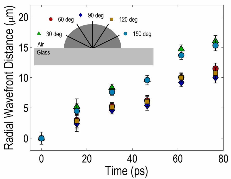
expansion of a plume caused by the laser irradiation. The 2D frame sequence helps us analyze
the complex angle-dependent plume wavefront in 2D (Fig. 3c) which the streak camera (only 1D
imaging) falls short in providing.
To highlight STAMP’s single-shot movie-shooting capability, we visualized the complex
dynamics of lattice vibrational waves (phonon-polariton waves) using STAMP at a much higher
frame rate than in the above demonstration. In general, imaging of phonons is essential for

understanding the physical properties of materials26,27, manipulating THz waves8,28,29, and
developing phononic devices9. As shown in Fig. 4a, we focused a cylindrically shaped
femtosecond laser pulse (pulse energy of 40 μJ, pulse width of 70 fs) into a ferroelectric crystal
wafer (LiNbO3) at room temperature to produce coherent phonon-polariton waves in the crystal
through impulsive stimulated Raman scattering and captured their dynamical evolution with
STAMP in a polarization-gating configuration. A detailed description of the phonon generation
and imaging apparatus is available in Supplementary Fig. 7. Shown in Fig. 4b and
Supplementary Movie 3 is a STAMP movie of the dynamics with 450 × 450 pixels, a short frame
interval of 812 fs (corresponding to a record high frame rate of 1.23 Tfps), and an average
exposure time of 1.02 ps. The figure insets, Supplementary Movie 4, and Supplementary Movie
5 with a finer frame interval of 229 fs show the irregular and complex electronic response of the
excited region in the crystal (t < 1 ps) followed by the formation of a coherent THz phonon-
polariton pulse and its upward propagation (t > 1 ps). The apparent speed of the phonon pulse is
determined from the movie to be 4.6 × 10⁷ m/s. From our time-domain and frequency-domain
analysis (Fig. 4c), the FWHM temporal width, center frequency, and FWHM bandwidth of the
pulse (averaged over all the frames) are found to be 337 ± 16 fs, 1.39 ± 0.09 THz, and 0.99 ±
0.16 THz, respectively. To the best of our knowledge, this is the first time that such a dynamical
behavior of phonons was captured by single-shot 2D imaging.
In this Letter, we have demonstrated STAMP in the most generic imaging configuration
at near-infrared wavelengths. We, however, note that STAMP’s general versatility allows
various imaging configurations by combining it with well-known standard techniques such as
differential interference contrast, diffraction imaging, holography, and tomography (3D
imaging). Furthermore, the operation of STAMP is not limited to optical wavelengths (including

near-infrared), but can be extended to other electromagnetic wavelengths such as infrared, THz,
and X-ray, provided that elements for temporal mapping and spatial mapping (not strictly limited
to dispersion) are available.
Methods
TMD. The TMD consists of a pulse stretcher and pulse shaper (Fig. 1, Supplementary Movie 1).
The pulse stretcher is used to temporally stretch a pulse by using a temporal disperser which may
be a glass rod, prism pair, grating pair, optical fiber, or any combination of these, depending on
the time scale of the dynamical event of interest (typically, glass rods for femtosecond frame
intervals, prism or grating pairs for picosecond frame intervals, optical fibers for nanosecond
frame intervals). The pulse shaper is used to produce a series of daughter pulses and tailor the
daughter pulses to be equal in intensity and pulse width to optimize the intensity resolution of the
image sensor as its dynamic range is fixed for all the image-encoded daughter pulses. The pulse
shaper in the TMD is essentially equivalent to the conventional pulse shaper that consists of two
identical diffraction gratings and two identical lenses that sandwich a mask (e.g., a liquid-crystal
spatial light modulator) located in the Fourier plane for phase modulation, two half-wave plates,
and two polarizing beamsplitters for amplitude modulation. The frame rate, exposure time, and
flash intensity of STAMP can be tuned by adjusting the settings of the pulse stretcher and pulse
shaper. The actual parameter values of the pulse stretcher and pulse shaper are described in
Supplementary Information.
SMD. The SMD consists of a diffraction grating, cylindrical mirror, and periscope array (Fig. 1,
Supplementary Movie 1, Supplementary Fig. 3, Supplementary Fig. 4). A Fourier-optical
representation of the SMD shown in Supplementary Fig. 3 indicates that the SMD is essentially

equivalent to the conventional pulse shaper except that the mask is replaced by the periscope
array which is a custom-made component composed of six pairs of dielectric mirrors for six
periscopes. As Supplementary Fig. 4 shows, the periscopes are designed such that the daughter
pulses travel the same propagation length, but exit the periscope ports at the different heights. To
form an image on the image sensor, we placed a set of cylindrical lenses in the direction
orthogonal to that of the cylindrical mirror to correct the beam ellipticity (Supplementary Fig. 2).
Also, an imaging lens is placed between the SMD and CCD. The actual parameter values of the
SMD are described in Supplementary Fig. 2 and Supplementary Information.
Theory of STAMP. Here we theoretically show the “designer’s equations” which can be used to
predict the performance of STAMP. The key parameters of STAMP are, just like in conventional
photography, (i) exposure time , (ii) frame rate , (iii) the number of pixels per frame , and
(iv) the total number of frames in the movie (which depends on the designer’s choice). To find
the exposure time, we first consider the evolution of an optical pulse (a STAMP daughter pulse
in this case) which is given by30 , / 0, exp ∑ ! , (1)
where 0, is the daughter pulse’s spectral profile with respect to the center angular
frequency , is the loss coefficient, is the propagation distance, are the group-velocity
dispersion coefficients of the temporal mapping device, and is the time in the
reference frame moving with the daughter pulse at the group velocity 1/ . In general, it is
convenient to consider only up to the second-order group-velocity dispersion in a narrow spectral
band and express Eq. (1) in terms of the dispersion parameter given by
, (2)
where is the speed of light in vacuum. Then, Eq. (1) is simplified to

, / 0, exp . (3)
Assuming that the spectral profile of the daughter pulse is Gaussian, it is expressed as
0, exp 2 ln 2 , (4)
where Δω is the FWHM bandwidth of the daughter pulse (which is equal to the total optical
bandwidth divided by the number of frames, assuming that the consecutive frames are spectrally
back-to-back). By substituting Eq. (4) into Eq. (3), the evolution of the optical pulse is given by , exp exp
exp . (5)
Then, the intensity can be written as | , | exp . (6)
From Eq. (6), the time-domain FWHM width of the daughter pulse which corresponds to the
exposure time is given by
Δ Δ . (7)
The first and second terms inside the square root of the right hand side in Eq. (7) correspond to
the Fourier-transform limit (so-called transform limit) and the effect of the TMD’s temporal
dispersion. Eq. (7) can be rewritten in terms of experimentalist-friendly parameters such as the
dispersion parameter in Eq. (2) and wavelength by
Δ , (8)
where 2 / and Δ 2 Δ / . Meanwhile, the frame rate is given by Δ . (9)

On the other hand, given the image sensor’s number of pixels , the upper bound on the number
of pixels per frame is given by
. (10)
These equations are simulated and plotted in Supplementary Fig. 8.
References
1. Edgerton, H.E. Flash!: Seeing the unseen by ultra high-speed photography (Hale, Cushman
& Flint, 1939).
2. Jussim, E., Kayafas, G. & Edgerton, H. Stopping Time: The Photographs of Harold Edgerton
(Harry N. Abrams, New York, 1987).
3. Ray, S.F. High Speed Photography and Photonics, (SPIE Press, Washington, 2002).
4. Hockett, P., Bisgaard, C.Z., Clarkin, O.J. & Stolow, A. Time-resolved imaging of purely
valence-electron dynamics during a chemical reaction. Nat. Phys. 7, 612–615 (2011).
5. Wong, C.Y. et al. Electronic coherence lineshapes reveal hidden excitonic correlations in
photosynthetic light harvesting. Nat. Chem. 4, 396–404 (2012).
6. Acremann, Y. et al. Imaging precessional motion of the magnetization vector. Science 290,
492-495 (2000).
7. Radu, I. et al. Transient ferromagnetic-like state mediating ultrafast reversal of
antiferromagnetically coupled spins. Nature 472, 205-208 (2011).
8. Feurer, T., Vaughan, J.C. & Nelson, K.A. Spatiotemporal coherent control of lattice
vibrational waves. Science 299, 374-377 (2003).
9. Maldovan, M. Sound and heat revolutions in phononics. Nature 503, 209-217 (2013).

10. Goda, K. et al. High-throughput single-microparticle imaging flow analyzer. Proc. Natl.
Acad. Sci. U.S.A. 109, 11630–11635 (2012).
11. Okie, S. Traumatic brain injury in the war zone. N. Engl. J. Med. 352, 2043-2047 (2005).
12. Kodama, R. et al. Fast heating of ultrahigh-density plasma as a step towards laser fusion
ignition. Nature 412, 798–802 (2001).
13. Velten, A. et al. Recovering three-dimensional shape around a corner using ultrafast time-of-
flight imaging. Nat. Comm. 3, 745 (2012).
14. Zewail, A.H. Laser femtochemistry. Science 242, 1645-1653 (1988).
15. Hajdu, J. et al. Analyzing protein functions in four dimensions. Nat. Struct. Biol. 7, 1006-
1012 (2000).
16. Zewail, A.H. Four-dimensional electron microscopy. Science 328, 187-193 (2010).
17. Barty, A. et al. Ultrafast single-shot diffraction imaging of nanoscale dynamics. Nat.
Photonics 2, 415-419 (2008).
18. Goda, K., Tsia, K.K. & Jalali, B. Serial time-encoded amplified imaging for real-time
observation of fast dynamic phenomena. Nature 458, 1145-1149 (2009).
19. Diebold, E.D., Buckley, B.W., Gossett, D.R. & Jalali, B. Digitally synthesized beat
frequency multiplexing for sub-millisecond fluorescence microscopy. Nat. Photonics 7, 806–
810 (2013).
20. Versluis, M. High-speed imaging in fluids. Exp. Fluids 54, 1458 (2013).
21. Matlis, N.H. et al. Snapshots of laser wakefields. Nat. Phys. 2, 749-753 (2006).
22. Frühling, U. et al. Single-shot terahertz-field-driven X-ray streak camera. Nat. Photonics 3,
523-528 (2009).

23. Ji, N., Magee, J.C. & Betzig, E. High-speed, low-photodamage nonlinear imaging using
passive pulse splitters. Nat. Methods 5, 197-202 (2008).
24. Gattass, R.R. & Mazur, E. Femtosecond laser micromachining in transparent materials. Nat.
Photonics 2, 219–225 (2008).
25. Zou, Y. et al. Developmental decline in neuronal regeneration by the progressive change of
two intrinsic timers. Science 340, 372-376 (2013).
26. Bargheer, M. et al. Coherent atomic motions in a nanostructure studied by femtosecond X-
ray diffraction. Science 306, 1771-1773 (2004).
27. Clark, J.N. et al. Ultrafast three-dimensional imaging of lattice dynamics in individual gold
nanocrystals. Science 341, 56-59 (2013).
28. Minami, Y., Hayashi, Y., Takeda, J. & Katayama, I. Single-shot measurement of a terahertz
electric-field waveform using a reflective echelon mirror. Appl. Phys. Lett. 103, 051103
(2013).
29. Feurer, T. et al. Terahertz polaritonics. Annu. Rev. Mater. Sci. 37, 317-350 (2007).
30. Agrawal, G.P. Nonlinear Fiber Optics (Academic Press, New York, 2007).
Acknowledgments
We thank M. Kaneda, M. Katsuragawa, K. Minoshima, and K. Yoshii for discussions and E.
Okada for assisting our experiments. This work was supported in part by the Translational
Systems Biology and Medicine Initiative from the Ministry of Education, Culture, Sports,
Science and Technology (MEXT), Japan. K. N. was partly supported by the Grant-in-Aid for the
Japan Society for the Promotion of Science (JSPS) Fellows. A. I. was partly supported by the

Photon Frontier Network Program of MEXT, Japan. K. G. was partly supported by the
Burroughs Wellcome Foundation.
Author contributions
K. N. conceived the concept of STAMP. K. N., A. I., Y. O., A. T., F. K. and I. S. designed the
STAMP camera. K. N., Y. O., A. N., K. H. and F. K. constructed the camera. K. N. and A. I.
carried out the imaging experiments. R. H. performed image processing for STAMP imaging. K.
G. carried out the theoretical analysis. H. L., K. G. and T. U. provided assistance to the camera
construction and imaging experiments. T. U., K. G., F. K. and I. S. supervised the project. K. N.,
K. G., F. K. and I. S. participated in writing of the manuscript.
Additional information
Supplementary information is available in the online version of the paper. Reprints and
permissions information is available online at www.nature.com/reprints. Correspondence and
requests for materials should be addressed to K. G. ([email protected]) and I. S.
Competing financial interests
The authors declare no competing financial interests.
Figure 1 | STAMP. Schematic of STAMP. An ultrashort laser pulse is split by the temporal
mapping device (TMD) into a series of discrete daughter pulses in different spectral bands,
which are incident onto the target as successive “flashes” for stroboscopic image acquisition

(which can be configured in reflection or transmission mode). The image-encoded daughter
pulses are “optically” and “passively” separated by the spatial mapping device (SMD) and
directed toward different areas of the image sensor. The data recorded by the image sensor is
digitally processed on the computer to reconstruct a motion picture (movie) with the frame
interval and exposure time calibrated from the settings of the TMD. The details of the TMD and
SMD are shown in the figure insets and described in Methods and Supplementary Information.
Note that the pulse colors in the figure are only for the illustrative purpose and do not represent
real wavelengths.
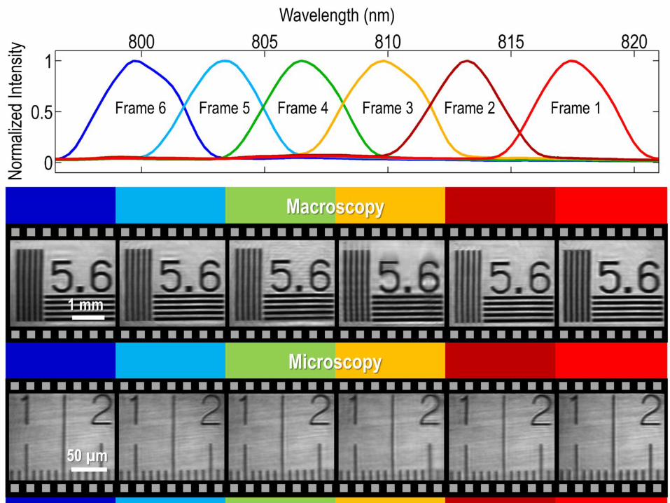
Figure 2 | Basic performance of STAMP. a, Performance of the TMD. Various frame intervals
of 229 fs, 812 fs, and 15.3 ps (corresponding to frame rates of 4.37 Tfps, 1.23 Tfps, and 65.4
Gfps, respectively) and exposure times of 733 fs, 1.02 ps, and 13.8 ps were obtained by adjusting
the settings of the TMD. b, Performance of the SMD. Shown in the figure are the spectra of the
daughter pulses that correspond to different movie frames. The images captured by the image
sensor indicate high pixel resolution in both macroscopic and microscopic imaging
configurations.
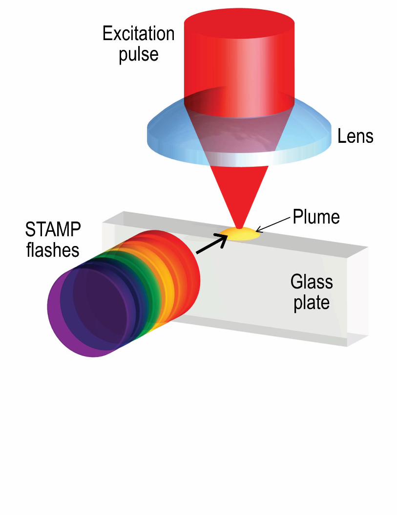
Figure 3 | Monitoring of plasma dynamics with STAMP. a, Schematic of the experiment. A
thin glass plate was ablated by a high-intensity femtosecond laser pulse for a micro-explosion
while the resultant dynamics was monitored at an angle perpendicular to the ablation pulse by
STAMP in a shadowgraph configuration. b, STAMP movie. Shown in the movie are the
generation of free electrons known as a plasma filament (corresponding to the dark area
indicated by the white arrow in the second frame) and the generation and expansion of a plume

caused by the laser irradiation. c, Evolution of the plume wavefront. The angle-dependent
analysis of the wavefront profile indicates slight asymmetry in its expansion.
Figure 4 | Observation of lattice vibrational waves with STAMP. a, Schematic of the
experiment. The crystal was excited by a cylindrically shaped femtosecond laser pulse to
produce lattice vibrational waves in the crystal via impulsive stimulated Raman scattering while
their dynamical evolution was monitored by STAMP. b, STAMP movie. Shown in the movie is
the irregular and complex electronic response of the excited region in the crystal (t < 1 ps)
followed by the formation of a coherent THz phonon-polariton pulse and its upward propagation
at approximately 15% of the speed of light, leaving the electronic response behind (t > 1 ps). The
figure insets show detailed dynamics captured by STAMP with a finer frame interval
(Supplementary Movie 4, Supplementary Movie 5). c, Temporal waveform (with its carrier
envelope) and corresponding spectrum of the propagating phonon pulse in each frame from t =
2167 fs to t = 3297 fs.