Embed Size (px)
Citation preview
NATURAL FREQUENCIES AND MODE SHAPES OF CABLES WITH ATTACHED MAS--ETC(U)
AUG 80 S SERGEV, W 0 IWANUNCLASSIFIED CEL-TN-1583 NL
"EIIIEEEEIIIHEIIIIIII

~BH 1.0 L~1112.8 *
Ill'l '----" m1111 11112.0
IIIJIL25II.4
MICROCOPY RESOLUTION TEST CHART
NATIONAL BURIJ Ak 0U STANDARDS ]')( A

V4 Iwow
./
TN no. N-1583
ti NATURAL FREQUENCIES AND MODE SHAPES
OF CABLES WITH ATTACHED HASSES D T .
author: S. Sergev and W. D. Ivan* DEC 1? 198
date: August 198o
sponsor: Naval Facilities Engineering Comand
program nos: YF59.556.091.01.402
*California Institute of Technology
ACIVIL ENGINEERING LABORATORYNAVAL CONSTRUCTION BATTALION CENTERPort Hueneme, California 93043
Approved for public release; distribution unlimited.
- s00

ACKNOWLEDGMENT
Professor Iwan developed the mode shape solution techniques
described here under contract to the Civil Engineering Laboratory.
The authors thank California Institute of Technology graduate
student Shawn Hall for his efforts in preparing the apparatus and
conducting the experiments to determine mode shapes.
:1

UnclassifiedSECURITY CLASSIFICATION OF THIS PAGE (65.. Des amw..4 _________________
*EPOT DOCUMENTATION PAGE BFR OPEIGFR1. 0EPOR M NU GOVT ACCESS,1ON NO . REC119IPIENT'S CATALOG NUM6ER
TN-15837 [DN787011 0 -,4,0f ; 9 44. TITLEa (.d AMwer.) S. TYPE of, REPORT a PERIOD COVEREO
NIATURAL I.REQUENCIES AND *ODE4,HAPES Not final; Jan 1978 - Apr 1979'OF ABLES WITH ATTCE J*SSES8 , S. PERFORMING OnG. REPORT NiUMBeR
4 .re si W. DIwa
IN. EFORMING ORGANIZATION NAME AND ADDRESS 16. PROGRAM ELEMENT. PROJECT. TASK
C5 IVIL UTIN AEMERNG. LABOATR ARApfORfNI)U~f
arved oruicn rettleasetrto unlimited
*I. SUPP RLEM NAR O TFIESN M N D R S n
Natual Fcqueies, modinern shape stumig cabes strumin cals-alyais
14 ITRIAE NCIN tehiu taOtSalow acrat 1ctallain OfiexreyIS hEUIh modeS numbers.Th
iS I 147 E~TON P I ~v ~lS BSOETEUnclassified
SECRIT CLASSIFICATION OTTEEN THIS PAGE (SRa O. .O
Approved for pulcrlae;dsrbtonulmtd

Unclassified
SECUMYY CLASSIFICATSON OF IGS PASCI~k. DOSe 9NlW*Q
20. Continued
-~To assess the accuracy of the program, a simple experiment was conducted to determinethe natural frequencies and mode shapes of a wire with attached masses driven sinusoidailyby a shaker. The algorithm shows close agreement with the experimental data.,
Library Card
- ------ Civ-ilg-wrig L-b-aot - INATURAL FREQUENCIES AND MODE SHAPES OF CA8BSWITH ATTACHED MASSES, by S, Sergrv and W. D. Iwan
ITN-1583 23 pp ilaa Augut19O Unclassffied
1. Strumming cables 2. Drag coefficients 1. YFS9.S56.091.O1.402
An alborithm has been developed to calculate mode shapes and natural freqencies Oftaut cables with attached masses. The transcendental equations of motion are soived by aniterative technique that allows accurate calculation of extremely high mode numbers. The
I algorithm has been implemented =a FORTRAN programn primarily as atool in determ.ining II drag coefficients of submerged strumming cables; however, any taut cable can be analyzed. ToIasses; the accuracy of the program, a simple experiment was conducted to determine the
n natural frequencies and mode shapes of a wire with attached masses driven simusidally by ashaker. The algorithm shows close agreement with the experimental data.
UnclassifiedaaCUNITY CLAISMPCATION Of ?NJ$ FAGC~Ub" Veto gnto"~d

CONTENTS
Page
INTRODUCTION . 1
STRUMMING OF MULTISEGHEN CABLE SYSTEMS . ............ 2
Cable Dynamics .. .. ........ ........ ..... 2Equations of Motion. .. ........ ........ ... 3
*Boundary Conditions. .. ........ ........ ... 4Solution Algorithm for Mode Shapes and Frequencies .. .. ... 6Summary of Solution Procedure .. ..... .......... 7
EXPERIMENTAL COMPARISON .. .. ....... ......... ... 8
EXPERIMENTAL VERSUS COMPUTER RESULTS .. ..... ......... 11
CONCLUSION. .. ........ ........ .......... 12
aaaonO For
NTIS G&WAkWIc TAB
iaounced
ifBe
caILas aaldcnnpem al
ti ()n
justif- icato_-
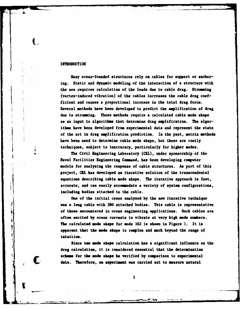
INTRODUCTION
Many ocean-founded structures rely on cables for support or anchor-
ing. Static and dynamic modeling of the interaction of a structure with
the sea requires calculation of the loads due to cable drag. Strumming
(vortex-induced vibration) of the cables increases the cable drag coef-
ficient and causes a proportional increase in the total drag force.
Several methods have been developed to predict the amplification of drag
due to struming. These methods require a calculated cable mode shape
as an input to algorithms that determine drag amplification. The algor-
ithms have been developed fro experimental data and represent the state
of the art in drag amplification prediction. In the past, matrix methods
have been used to determine cable mode shape, but these are costly
techniques, subject to inaccuracy, particularly for higher modes.
The Civil Engineering Laboratory (CEL), under sponsorship of the
Naval Facilities Engineering Comand, has been developing computer
models for analyzing the response of cable structures. As part of this
project, CIL has developed an iterative solution of the transcendental
equations describing cable mode shape. The iterative approach is fast,
accurate, and can easily accommodate a variety of system configurations,
including bodies attached to the cable.
One of the initial cases analyzed by the new iterative technique
was a long cable with 380 attached bodies. This cable is representative
of those encountered in ocean engineering applications. Such cables are
often excited by ocean currents to vibrate at very high mode numbers.
The calculated mode shape for mode 162 is shown in Figure 1. It is
apparent that the mode shape is complex and much beyond the range of
intuition.
Siace Le mode shape calculation has a significant influence on the
drag calculation, it is considered essential that the determinationk schem for the mode shape be verified by comparison to experimental
data. Therefore, an experiment was carried out to measure natural
II

frequencies and mode shapes. The description of the iterative algorithm,
the measured results of the experiment, and a comparison between the
experimental data and the computed results are presented.
4.00 in. mode no. 162
-4.00 in. 15,400 ft
Figure 1. High mode number for a real cable system.
4 STRUMING OF HULTISEETT CABLE SYSTHS
The amplitude of oscillation and the effective drag coefficient of
a strumming cable system are determined in the following analysis. The
natural frequencies and mode shapes of cable oscillation are obtained by
an iterative substitution algorithm that finds the solution satisfying
the imposed boundary conditions of the problem.
Cable Dynamics
The cable system considered is shown in Figure 2. It consists of
n cable segments attached to n-i masses. The cable segments have an
effective mass per unit length, pi, and a tension, Ti, which is assumed
to be constant over the length, ki, of the segment. The effective
attached mass (including added mass) is H..1
2

y
1 1 n n
vx
Figure 2. System of masses and cable segments.
Equations of Motion
The equation of motion for the displacement yi of the i cable
segment, assuming no bending rigidity, is (see Figure 3)
II8 2yi a2yi
Pi = T - i = ,.,n (1)aty2 ax2 "'
YOMt
i-1 TiP i
Figure 3. Displacement of the ith segment.
The harmonic solution of this equation has the form
yi(x,t) = Yi(x) e (2)
where Yi(x) gives the shape of the deformation, and w is the frequency
of oscillation. Substituting Equation 2 into Equation 1 gives
4 3
Y(x) = A sin ai w x + Bi Cos a i t x 0 S x SI i (3) 11 1 i,.1.1
where ai =4 7ii (4)
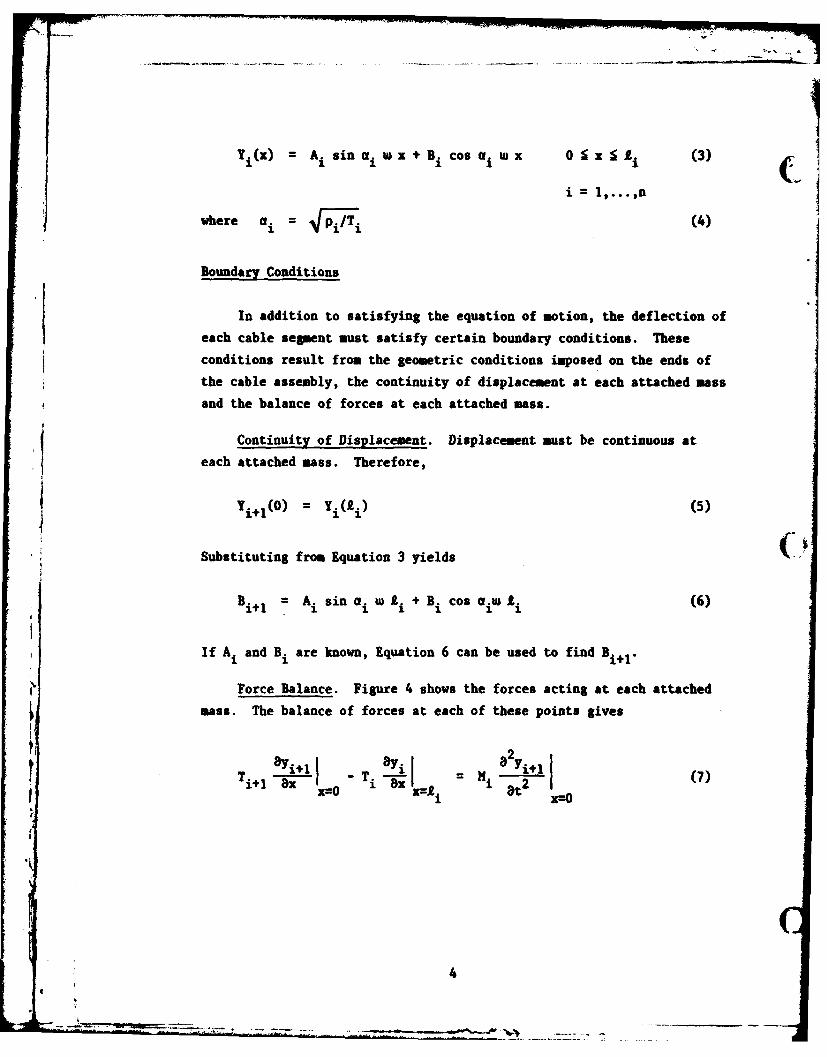
Boundary Conditions
In addition to satisfying the equation of motion, the deflection of
each cable segment must satisfy certain boundary conditions. These
conditions result from the geometric conditions imposed on the ends of
the cable assembly, the continuity of displacement at each attached mass
and the balance of forces at each attached mass.
Continuity of Displacement. Displacement must be continuous at
each attached mass. Therefore,
Yi+l (O) = Yi(Ii) (5)
Substituting from Equation 3 yields
Bi 1 A i sin ai W 0i + Bi Cos aIW i (6)
If AI and Bi are known, Equation 6 can be used to find Bi+1 .
Force Balance. Figure 4 shows the forces acting at each attached
mass. The balance of forces at each of these points gives
!!-T i = a (7)Ti+ ex x=O i 2 x--O
ILX-

x
Figure 4. Force balance.
Substituting from Equation 3 yields
Ti+ ai+l Ai+ - (ai Ai cos ai wi &- a. B. sin a. w A) T. = - N. w Bi 1 (8)
111 1,...,n
Using Equation 6 and solving Equation 8 for Ai + gives
A: i 1 ai T. csi a. co a Wi w sin ai W ASi~l ai+ T i+ 1 i
I(ai Ti sinai.i +iWCos ai 2i) Bi] (9)
j If Ai and Bi are known, Equation 9 can be used to find Ai I .
Geometric Boundary Conditions. At the left-hand end of the cable
assembly, the displacement is assumed to be zero. Thus,
Y1 (0) = 0 (10)
Substituting from Equation 3 thus implies that
B1 = 0 (11)
* .
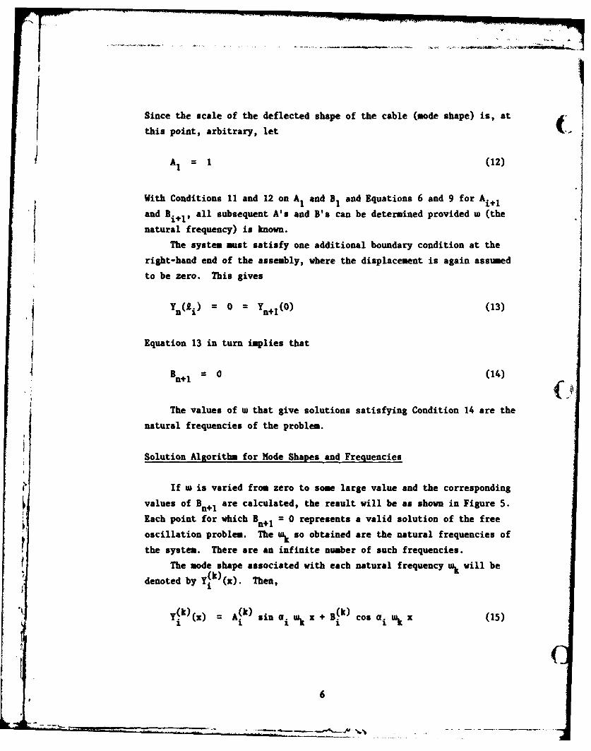
Since the scale of the deflected shape of the cable (mode shape) is, at
this point, arbitrary, let
A1 = 1 (12)
With Conditions 11 and 12 on AI and B1 and Equations 6 and 9 for Ai+Iand Bit,, all subsequent A's and B's can be determined provided w (the
natural frequency) is known.
The system must satisfy one additional boundary condition at the
right-hand end of the assembly, where the displacement is again assumed
to be zero. This gives
Yn(i) = 0 = Ynol(0) (13)
Equation 13 in turn implies that
Bn 1 =0 (14)
The values of w that give solutions satisfying Condition 14 are the
natural frequencies of the problem.
Solution Algorithm for Mode Shapes and Frequencies
If w is varied from zero to some large value and the corresponding
values of Bn+1 are calculated, the result will be as shown in Figure 5.
Each point for which Bn = 0 represents a valid solution of the free
oscillation problem. The wk so obtained are the natural frequencies of
the system. There are an infinite number of such frequencies.
The mode shape associated with each natural frequency wk will be
denoted by Y k)(z). Then,
(~k) (k) (k)Y.x . sin aiwk x +B Cos a i'k (15)1 1 1 a 1 1
p6
- - . --..~
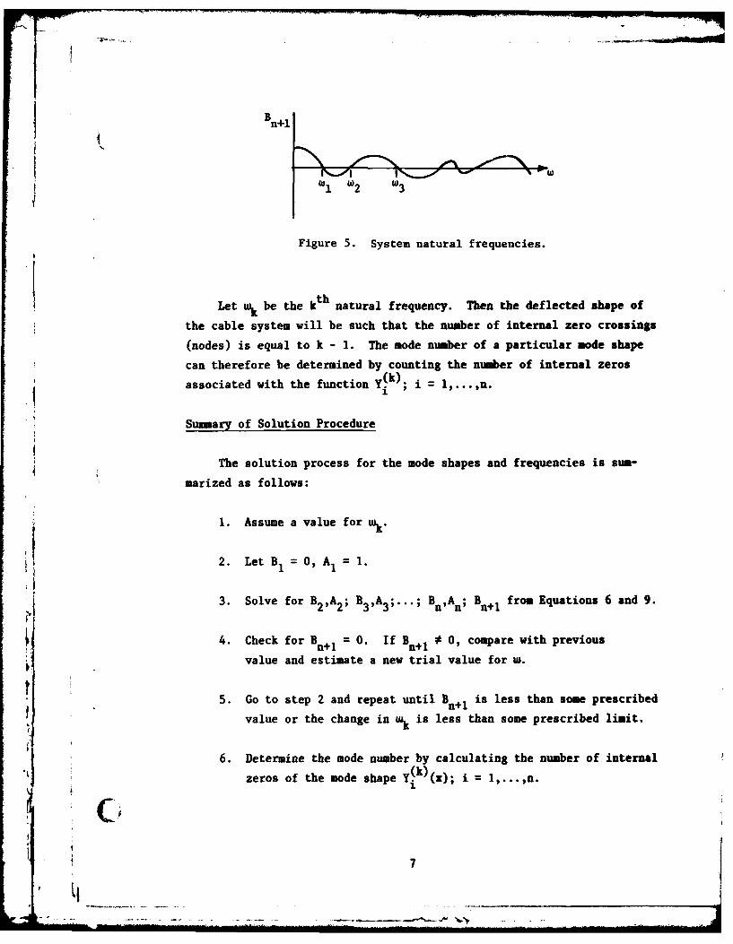
Bn+l
Figure 5. System natural frequencies.
Let wk be the kth natural frequency. Then the deflected shape of
the cable system will be such that the number of internal zero crossings
(nodes) is equal to k - 1. The mode number of a particular mode shape
can therefore be determined by counting the number of internal zeros
associated with the function Y(k) = 1,.,n
Summary of Solution Procedure
The solution process for the mode shapes and frequencies is sum-
marized as follows:
1. Assume a value for wk -
2. Let B 1 O, A1 = 1.
3. Solve for B2,A2 ; B3,A3 ;...; Bn,An; Bn+I from Equations 6 and 9.
4. Check for Bn+ 1 = 0. If Bn+ 1 0, compare with previous
value and estimate a new trial value for w.
5. Go to step 2 and repeat until B n+ is less than some prescribed
value or the change in wk is less than some prescribed limit.
6. Determine the mode number by calculating the number of internalzeros of the mode shape ( k)(x); i 1,...,n.
7f Cx.;.i...1,..... ..
EXPERIHTAL COIPARISON (
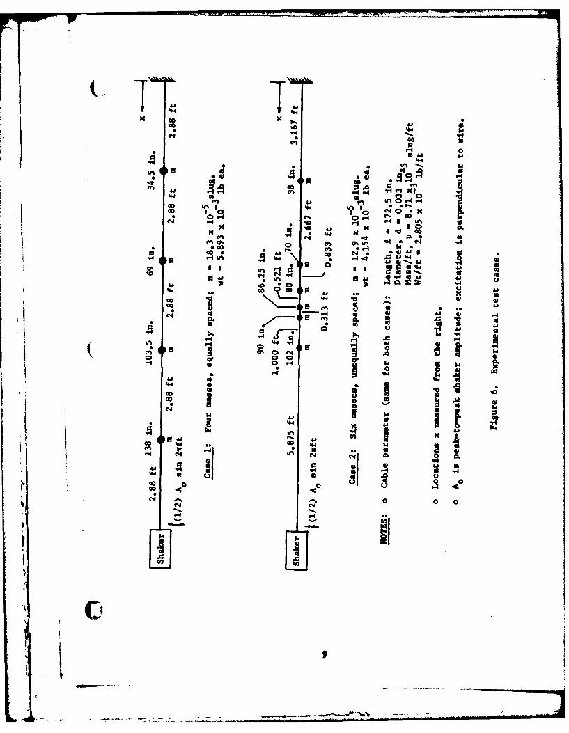
In order to verify the accuracy of the algorithm, a simple, easily
conducted experiment was designed. A taut piano wire was fixed at one
end and excited sinusoidally at the other end by a shaker; natural
frequencies were determined by varying the excitation frequency. The
experimental configuration is shown in Figure 6; wire properties are
given in the figure. Two cases of attached bodies were considered:
Case 1: Four equally spaced bodies, each with a mas of
18.3 x 10 "5 slug
Case 2: Six unequally spaced bodies, each with a mass of
12.9 x 10 "5 slug
The objective of the experiment was to find the first 8 to 10
natural frequencies and mode shapes for each case for comparison with
calculations.
Tension was measured by shaking the unloaded wire (no attached
masses) in the 5 th mode (a = 5). Period x5 (sec) was measured by a
digital counter accurate to 0.01 mas. Tension T (lbf) was then calcu-
lated by the natural frequency formula for an ideal cable:
= 2 0-.,T =
Split-shot lead weights (the type used in fishing) were attached at
appropriate locations with a small amount of contact cement.* When ten
samples of shot were weighed, the mass variation (standard deviation)
for a given size of shot was found to be about t1% of the mean value
cited. The size of the masses was approximately 0.32 inch in the x-
direction.
*The cement was necessary to prevent the masses from shaking looseduring the tests; its weight is assumed negligible.
iI-t8
"S ' 41'044 4
40 0 0c
00 '-4 P
0~r 41. .
00
'.4 0 4
.4' 0.(4
ao' 44 to4 .- t W ~ .
cc ** 008
'44 0 0 0 P4 44~
C4 0 C441
414
0 4 0.
0y r Pkl
00 414.
a 4J4 ao '4 4
000at 4 1 .
C.' 4s~d 6I 1 H
4 ''N

Except for some very high frequency noise caused by air rushing
through the shaker's air bearing, excitation was harmonic, as measured (by an accelerometer mounted directly on the shaker. For each experimental
run, the shaker's displacement amplitude, A0 , was reckoned from
Displacement Amplitude = 2 (Acceleration Amplitude)(2 X f)2
The antinode amplitudes recorded in the data have not been corrected for
the shaker amplitude (the correction is usually negligible). However,
if the correction is desired, the following formula should be used:
AA x an t inod e
corrected = measured - Ao
The shaker frequency, f, was monitored by a digital counter capable
of measuring the period to within ±0.01 is. Experimentally, the shaker
frequency, f, was decreased from some arbitrary frequency, fa' lying
well above fn' to at which point a sudden, highly visible increase
in amplitude occurred. The frequency, fb' was then recorded as the"natural frequency."
The location of nodes was measured by eye or, in the rare case ofvery small amplitudes, with the help of a small strip of paper againstthe vibrating wire. Obviously, the uncertainty in measurement is least
where the nodes are well defined; i.e., when the surrounding antinodes
have large amplitude and/or are close together. Thus, depending on the
mode shape, accuracy varied from about ±0.1 inch to about ±0.75 inch.
In general, of all the quantities measured, node location was the most
accurate.
The location of the antinode was also measured by eye. Judgment of
antinode location by this method is very difficult, inasmuch as the
antinodes are not sharply defined. Every effort was made to make the
measurement as accurate as possible without resorting to sophisticatedequipment. A rule was placed a short distance below the wire and observed
from a fixed distance above the wire. A strobe light running slightly
10

slower or faster than the vibration frequency was used to illuminate the
vibrating wire; this made the wire appear to oscillate slowly in its
mode shape. In this way, the amplitude, Ameasured, which is reported in
the data tables, was read to an estimated accuracy of 0.01 inch.
Three runs of mode 5, Case 1 were made in succession. Two runs
were as identical as possible, with four masses equally spaced. For the
third, the mass at x = 138.0 inches was moved to x = 138.1 inches. On
the basis of these runs, it was concluded that the repeatability of the
antinode amplitude measurements was of the order of 5%, and could be as
large as 10% under circumstances less controlled than those in the tests
described. It was also observed that the amplitude ratios were fairly
critically dependent upon the exact location of the masses.
To judge the bias in the measurements caused by the asymmetrical
excitation (shaker at one end), several cases were rerun with the con-
figuration of the masses mirrored about x = 1/2. The predominant effect
of asymmetrical excitation is a preference for certain modes over others.
For example, in one run, mode 10 was easily excitable, but not excitable
at all in the mirrored run. The reverse was true for mode 8.
EXPERIMENTAL VERSUS COMPUTER RESULTS
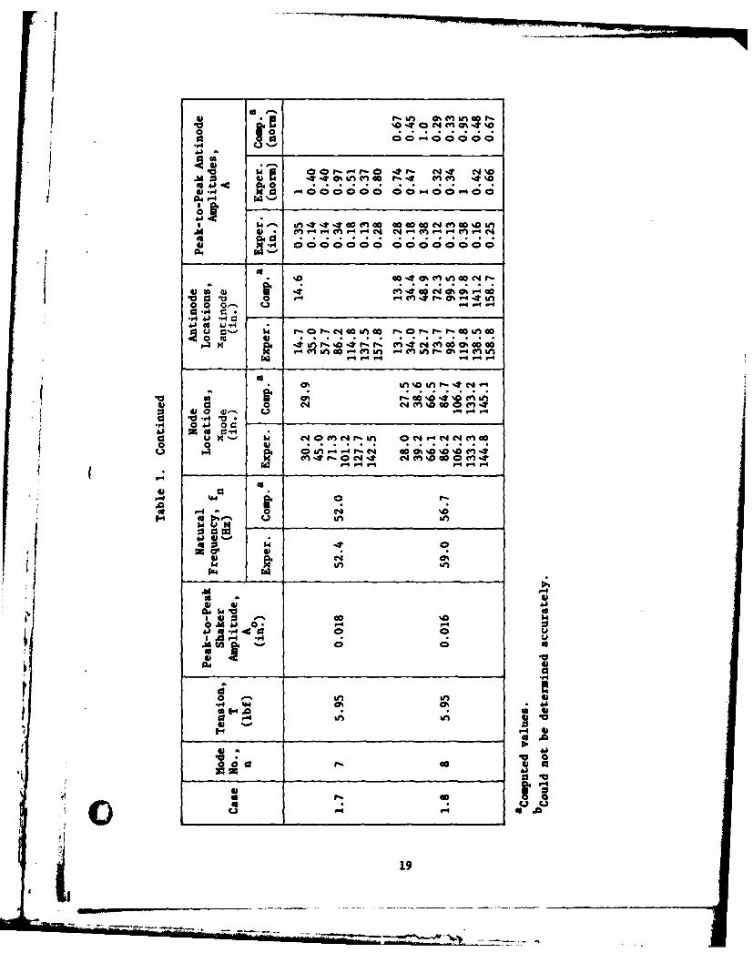
if From Tables I and 2 it is observed that the agreement between the
calculated and experimentally determined natural frequencies is well
within the range of the expected experimental error. The node and
antinode locations also show good agreement, especially for the lower
mode numbers. Modes of order eight and higher were rather difficult to
observe accurately with the experimental setup. However, the results
for the higher modes still appear to verify the computer model.
Response amplitude was compared on a normalized basis. To compare
on an absolute basis would have required that both internal and external
damping be known and modeled and that the precise nature of the excitation
be known. Since this information was not readily available, the nor-
malized response was used for comparison. As showa in the tables, the
normalized amplitudes of response compare favorably.
, 11
-J_- - -

The nature of the mode shapes of the first 15 modes for the six
was cases is indicated in Figure 7. Modes I through 10 are those
presented in Table 2. The additional modes shown illustrate that the
non-uniformly distributed masses cause the mode shapes to become
increasingly complex. It is interesting to note that the sinusoidal
portions of the mode shapes, shown clearly in mode 15, but also evident
in other modes, represent the free response of the wire unaffected by
the attached masses. This figure was generated by the computer algorithm.
CONCLUSION
A new computer algorithm for computing the natural frequencies andmode shapes of cable systems has been presented. This algorithm is
computationally efficient and shows excellent convergence, even for very
high mode numbers. The algorithm is also quite flexible since it has
the capacity for treating a wide range of different system configurations.A comparison of the results of the computer model with the results
of an experimental study of a vibrating cable system in air has shown
that the model accurately predicts the natural frequencies, node and
antinode locations, and relative response amplitudes for all modes
obtainable experimentally. The extremely close agreement obtained for
modes up to number 10 does not insure that higher mode shapes are correctlycalculated, but it does give increased confidence that the solution
technique can be validly extrapolated as required by the users needs.
pt
12
ML ,

p p
C).
130

LLJ LC
/ic(I / I
I14

jt
CIO.
I.I.'
/ zz 6
ED- I- /
~(
\N
rr
\/
* i 15i,-

C3
n- - f

-Y -vIL
/
7(
2 6I*144J
II 0
0 0 0 I.-
- - z -~ 0Sd
LiJ LU 114en en en0 0 0
U a a
17

0 '0% C4 00'm g In in en '0C'J0en
44 "4, Cos 00" V04 0-4 W"40 0 0 00 13
A4 00 4 * 0I4
va- 00"4 000-"4 0 0
ld.' V- 'ON inN ata0% (n0*4 CD N"0 O4;N010 4S * n M M4" r-.0r M 0' D0 Mr lC ~(~C4 LA 4 4 4 Lm
a 0
4) ed 4
r 4
:3 ~ . ON ~)0 ' 0% '.4 P-t %T 00 1-4 0D0NV)D-*
LA .6 4 __ 0
4)- 0
ta a U I C4 r-- c 0II" M -*0I 0 L ,-c4 L '0 0=4 0n 0Q In4 %-O T 0%O' M co r00 0
co 4)0 r"- abU4 c) c4 ( n% o0
0wa
"4 ~ 0 0 (' 0 n gn P
4)..
4)0
0 in in g n n%
00 0' hWN "A'A-
lu0
0 0 0 08
.4 4141 .
93 0O4 0 0
N S0 %
a aca1 0%
41 m 1 4.pa x w;9U;r ;4 c ic ar4V n4o1 Mi .4Mk r- % I- c w
4J0 e4 A 0
r-:- .r4 *i U s Z0n-Tr 0 Nf NMac 0 (n0
u Un
N00o~i ssf f14
0 Af I n
44 4-* 416
r- 4.
* 19

.041
.1 0 go 'n mt a~--toC4ma 41 0 0 %00 %0 . 00 0%4m LI F * n m 6
wl 41
at 4 *e4 O 40%%% .?~fP (40 "4Il C- 4 q l 0%f-.ifl. . . . . . . . . . . . . ."0 0 M "4 00" 4 %D v C4 00 V4 nr- 0 000C 0
(1 00'n0 000 0000 0000 0
044aa
v1 .0 al.- U~r
co kAau C4M r4 co m" f-..- 04-4 (r
"4 -4"iIN4;0* 4-
I 4 0 tnX 040 r-4 '0@% 44%aGo0
.r4
04
414 a',N_ __ _ _ _ __ _ _ _ __ _ _ _ _
S 0 14 -10' 41 0 - C4 - nI
A 41 a na
140 a.
1.4 p.4 C4C4
M20

0u - Y% It'* '. u 0 iL-a0 t0% M &0ICJ%~ 00C1'e u-4*O%
93. i cc 04 000r-
02
a)4 4J 04. 04NW %e 4 4% %42b 4J.1 * C C -
K '4 OON inMm% mma %O %.@ 0 4 Ln
@3 0,- u ' Pr-O0-r4 C:bO
mJ 4J"4
u 0 : 40 ~ p tvv . . .. . .
---
4) 0
41 0 r41I go ' r. H
00 U $ 4 0 0 r
eq .4 L V
00
00 r- Q.
41-
40 .*
r. N (4
-~~C - .4 '

ici
DISTRIBUTION LIST
AFB CESCH, Wright-PattersonARMY ARRADCOM, Dover, NJARMY - CERL Library, Champaign ILARMY COASTAL ENGR RSCH CEN Fort Belvoir VAARMY COE Philadelphia Dist. (LIBRARY) Philadelphia, PAARMY ENG WATERWAYS EXP STA Library, Vicksburg MSARMY ENGR DIST. Library, Portland ORARMY MOBIL EQUIP R&D COM Fuel Hndlng Equip Br., Ft Belvoir, VA; Mr. Cevasco, Fort Belvoir MDCNM MAT 08'"245 (Spalding). Washington, DCCOMSUBDEVGRUONE Operations Offr, San Diego, CADOE Dr. CohenDTNSRDC Code 522 (Library), Annapolis MD; Pattison, Code 1706, Bethesda, MD; Rispin, Code 1706,
Bethesda, MDLIBRARY OF CONGRESS Washington, DC (Sciences & Tech Div)NATL RESEARCH COUNCIL Naval Studies Board, Washington DCNAVCOASTSYSTCTR Library Panama City, FLNAVELEXSYSCOM Code PME-124-61, Washington DC; PME 124-30 (Henderson) Washington, DCNAVFACENGCOM Code 0453 (D. Potter) Alexandria, VA; PC-2 Alexandria, VANAVFACENGCOM - CHES DIV. Code FPO-IE, Wash. DCNAVOCEANO Code 1600 Bay St. Louis, MSNAVOCEANSYSCEN Code 4473 Bayside Library, San Diego, CA; Code 5204 (J. Stachiw), San Diego, CA;
Tech. Library, Code 447NAVSCOLCECOFF C35 Port Hueneme, CANAVSEASYSCOM Code SEA OOC Washington, DCNAVSEC Code 6034 (Library), Washington DCNAVSHIPREPFAC Library, GuamNAVSHIPYD Code 202.4, Long Beach CA; Code 202.5 (Library) Puget Sound, Bremerton WA; Library,
Portsmouth NH; Tech Library, Vallejo, CANOAA Library Rockville, MDNOAA DATA BUOY OFFICE Engrng Div (Riannie) Bay St. Louis, MSNORDA CO, Bay St. Louis, MS; Code 350 (Swenson) Bay St. Louis, MSNRL Code 2627, Washington DC; Code 8400 Washington, DC; Code 8441 (R.A. Skop), Washington DCNUSC Code 131 New London, CT; Code S332, B-80 (J. Wilcox)OCEANAV Mangmt Info Div., Arlington VAONR (Dr. E.A. Silva) Arlington, VA; Central Regional Office, Boston, MAPMTC Code 4253-3, Point Mugu, CAPWC Code 120, Oakland CA; Code 154, Great Lakes, ILUCT TWO OIC, Norfolk, VAU.S. MERCHANT MARINE ACADEMY Kings Point, NY (Reprint Custodian)US NATIONAL MARINE FISHERIES SERVICE Highlands NY (Sandy Hook Lab-Library)USCG (G-MP-3/USP/82) Washington DcUSCG R&D CENTER CO Groton, CT; D. Motherway, Groton CT; D. Paskausky, Groton, CT; Tech. Dir.
Groton, CTUSNA Ch. Mech. Engr. Dept Annapolis MD, Ocean Sys. Eng Dept (Dr. Monney) Annapolis, MDAMERICAN CONCRETE INSTITUTE Detroit MI (Library)CALIF. MARITIME ACADEMY Vallejo, CA (Library)CALIFORNIA INSTITUTE OF TECHNOLOGY Pasadena CA (Keck Ref. Rm)CATHOLIC UNIV. Mech Engr Dept, Prof. Niedzwecki, Wash., DCCORNELL UNIVERSITY Ithaca NY (Serials Dept, Engr Lib.)DAMES & MOORE LIBRARY LOS ANGELES, CADUKE UNIV MEDICAL CENTER B. Muga, Durham NCFLORIDA ATLANTIC UNIVERSITY Boca Raton FL (W. Tessin)LEHIGH UNIVERSITY Bethlehem PA (Linderman Lib. No.30, Flecksteiner)MAINE MARITIME ACADEMY CASTINE, ME (LIBRARY)
22

MIT Cambridge MA; Cambridge MA (Rm 10-500, Tech. Reports, Engr. Lib.)NATL ACADEMY OF ENG. ALEXANDRIA, VA (SEARLE, JR.)OREGON STATE UNIVERSITY (CE Dept Grace) Corvallis, ORPENNSYLVANIA STATE UNIVERSITY State College PA (Applied Rsch Lab)PURDUE UNIVERSITY Lafayette, IN (CE Engr. Lib)SOUTHWEST RSCH INST R. DeHart, San Antonio TXSTANFORD UNIVERSITY Engr Lib, Stanford CASTATE UNIV. OF NEW YORK Buffalo, NYUNIVERSITY OF HAWAII HONOLULU, HI (SCIENCE AND TECH. DIV.); Ocean Engrng DeptUNIVERSITY OF ILLINOIS URBANA, IL (LIBRARY)UNIVERSITY OF MASSACHUSETTS (Heronemus), Amherst MA CE DeptUNIVERSITY OF NEW HAMPSHIRE (Corell) Durham, NHUNIVERSITY OF NOTRE DAME Katona, Notre Dame, INUNIVERSITY OF RHODE ISLAND Narragansett RI (Pell Marine Sci. Lib.)UNIVERSITY OF SO. CALIFORNIA Univ So. CalifUNIVERSITY OF TEXAS Inst. Marine Sci (Library), Port Arkansas TXAMETEK Offshore Res. & Engr DivCOLUMBIA GULF TRANSMISSION CO. HOUSTON, TX (ENG. LIB.)EG&G WASH ANALYTICAL SERV CTR, INC Rockville, MDEXXON PRODUCTION RESEARCH CO Houston TX (A. Butler Jr)GOULD INC. Shady Side MD (Ches. Inst. Div., W. Paul)GRUMMAN AEROSPACE CORP. Bethpage NY (Tech. Info. Ctr)HONEYWELL, INC. Minneapolis MN (Residential Engr Lib.)MOBIL PIPE LINE CO. DALLAS, TX MGR OF ENGR (NOACK)OCEAN ELECTRONICS APPLICATION, INC. (Softiey) Key Biscayne, FLSANDIA LABORATORIES Library Div., Livermore CATRW SYSTEMS CLEVELAND, OH (ENG. LIB.)WESTINGHOUSE ELECTRIC CORP. Annapolis MD (Oceanic Div Lib, Bryan)WESTINTRUCORP Egerton, Oxnard, CAWM CLAPP LABS - BATI'ELLE DUXBURY, MA (LIBRARY)
i2
Il
23S