Embed Size (px)
Citation preview

The Marquette Interchange in downtown Mil-waukee includes three Interstate highways—I-94, I-794, and I-43—and is the cornerstone
of the southeastern Wisconsin freeway system. The $810 million reconstruction and reconfigura-tion of this interchange includes a five-level sys-tem interchange, five miles of Interstate highway, 28 ramps, more than 60 bridges—totaling 2.1 million sq. ft of bridge deck—and five miles of retaining wall.
The preliminary engineering phase identified two feasible bridge types for the system ramps: trapezoidal steel box girders and concrete segmen-tal box girders. After 14 months of engineering and cost analysis, the decision was made to move for-ward with the steel option.
The centerpiece of the project consists of eight high-level system ramps, all of which are curved multispan twin steel composite box-girder bridges up to 2,400 ft long. Individual bents range up to 1,600 ft long between movement joints.
So far, several bridges have been completed and opened to traffic. One of these bridges is the South-to-Plankinton Structure B-40-1131, with a main span of 250 ft over active railroad tracks.
Unique HPS UseHigh-performance steel is a superior product
with higher yield strength, improved weldability and weathering resistance, and greater levels of toughness, all of which can lead to more economi-cal bridges than conventional 50W designs. How-ever, at the time, the Guide Specifications would not allow use of hybrid section designs. As such, for Bridge No. 1131 and other tub girder designs in the project, a design using HPS 70W and HPS 50W for adjacent field section elements provided both the function and cost benefits needed on a large project like the Marquette Interchange. This hybrid element approach involved using the higher strength HPS 70W material in the pier units, where strength mattered the most due to higher moments, and HPS 50W in the mid-span sections to take advantage of its superior material toughness.
With the Marquette Interchange project being 75% comprised of bridge structure, delays in steel delivery—and especially of the HPS steel for the bridges—would have spelled disaster. A key to the success and time savings realized on the project was getting the steel ordered as soon as possible, especially for the early bridges on the critical path. Typically, it takes several weeks or even months from the time of award to placing a steel order with the mills. To avoid this delay and expedite the steel order, all structures on the critical path were identified, and shop drawings were prepared in sufficient detail to place a mill order immediately upon award to the successful contractor. This advance order ensured delivery of the HPS steel to the fabricator in a timely manner and drastically reduced the risk of project delays. To date the project is nearing completion and is about six months ahead of schedule.
Marquette Interchange Bridge B-40-1131Milwaukee
NatIoNal Steel BrIdge allIaNce PrIze BrIdge coMPetItIoN
MerIt aWardS loNg SPaN
OwnerWisconsin Department of Transportation,
Madison
DesignerMilwaukee Transportation Partners, LLC,
Milwaukee
FabricatorPDM Bridge, Eau Claire, Wis. (AISC Member)
DetailerTensor Engineering Co., Indian Harbour Beach,
Fla. (AISC Member)
General ContractorMarquette Constructors, LLC, Black River Falls,
Wis.
MODERN STEEL CONSTRUCTION november 2007
MaJor SPaN
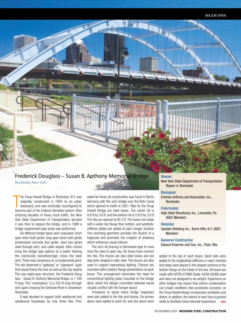
Frederick douglass – Susan B. anthony Memorial Bridgerochester, New York
OwnerNew York State Department of Transportation
Region 4, Rochester
DesignerErdman Anthony and Associates, Inc.,
Rochester
FabricatorHigh Steel Structures, Inc., Lancaster, Pa.
(AISC Member)
DetailerUpstate Detailing Inc., Burnt Hills, N.Y. (AISC
Member)
General ContractorEdward Kraemer and Son, Inc., Plain, Wis.
The Troup Howell Bridge in Rochester, N.Y. was originally constructed in 1954 as an urban boulevard, and was eventually reconfigured to
become part of the Federal Interstate system. After enduring decades of heavy truck traffic, the New York State Department of Transportation decided it was time to replace the bridge, and in 1999 a bridge replacement type study was performed.
Six different bridge types were evaluated: short-span steel multi-girder, long-span steel multi-girder, prestressed concrete box girder, steel box girder, steel through arch, and cable stayed. After consid-ering the bridge type options at a public hearing, the community overwhelmingly chose the steel arch. There was consensus on a fundamental point: The site deserved a “gateway” or “signature” span that would frame the river as well as the city skyline. The new eight-span structure, the Frederick Doug-lass - Susan B. Anthony Memorial Bridge, is 1,194 ft long. The “centerpiece” is a 433-ft-long through arch span crossing the Genesee River in downtown Rochester.
It was decided to support both eastbound and westbound travelways by only three ribs. Prec-
edent for three-rib construction was found in Berlin, Germany with the arch bridge over the Britz Canal, which opened to traffic in 2001. Ribs for the Troup Howell Bridge are steel boxes. The center rib is 9.8 ft by 3.8 ft, and the exterior rib is 5.8 ft by 3.8 ft. The ribs are spaced at 65.3 ft. The boxes are made with a wider top flange than bottom, and aesthetic stiffener plates are added at each hanger location. This overhang geometry provides the illusion of a trapezoid and promotes the creation of shadows, which enhances visual interest.
The arch rib bracing is Vierendeel-type to maxi-mize the view to open sky. Six brace lines connect the ribs. The braces are also steel boxes and are dog bone-shaped in plan view. The braces are also used to support expressway lighting. Fixtures are mounted within bottom flange penetrations at each brace. This arrangement eliminates the need for conventional lighting poles mounted on the bridge deck, which the design committee believed would visually conflict with the hanger layout.
Provisions to assist future bridge inspectors were also added to the ribs and braces. Six access doors were added to each rib, and two doors were
added to the top of each brace. Hand rails were added to the longitudinal stiffeners in each member, and steps were placed in the steeper portions of the bottom flange on the inside of the box. All boxes are made with ASTM A709M Grade 345W (A588) steel and were not designed to be airtight. Experience on other bridges has shown that interior condensation can create conditions that accelerate corrosion, so the Troup Howell design incorporates ventilation and drains. In addition, the interior of each box is painted white to facilitate future biennial inspections.
november 2007 MODERN STEEL CONSTRUCTION

ramp B, Interstate 40Nashville
Ramp “B” spans Briley Parkway and Ramp “A” on the east side of Nashville, Tennessee. This structure replaces the old at-grade intersec-
tion with a flyover from I-40 west to southbound Briley Parkway.
A major concern at this location is Nashville International Airport, which has a runway termi-nating in the proximity of this interchange. Since there’s a flight path directly over the interchange, numerous configurations of both the bridge and interchange were considered. A minimum verti-cal clearance for I-40 below and maximum verti-cal height restrictions for air traffic above resulted in a shallow zone of air space being allocated to accommodate the bridge. The shallow steel girder and integral cap ultimately employed by the Ten-nessee Department of Transportation effortlessly conformed to the constricted and winding corridor of space prescribed for passage of the superstruc-ture. The 45:1 span to girder depth ratio imparts a slender line to the bridge as it courses gracefully without intrusion across the skyline.
Each of the bent caps utilized in this struc-ture consists of a steel box with access doors for inspection. The box connection to the curved plate girders is accomplished using bolted field splices. The novel aspect of the longitudinal top and bottom flange splice plates is that they bridge uninterrupted over and under the bent cap providing a direct con-nection of opposing girders. This configuration miti-gates transverse stresses in the bent cap flanges. The flange splice plates are bolted to the bent cap only minimally to satisfy seal and stitch require-ments. Neoprene sheets are sandwiched between flange splice and filler plates to further isolate the cap from girder longitudinal stresses. The webs of the plate girder are bolted to a transverse stiffener on the outside of the box. The inside of the box has a transverse stiffener between opposing gird-ers, which provided a continuous web connection across the box as well. The fracture-critical steel box girder was fabricated using high performance Grade 50 steel on the top tension flange and each web plate. The steel caps bear on a single bearing pin, which allows rotation of the super structure and restrains uplift attributed to unbalanced load condi-tions. The lugs supporting the bearing pins are field-welded to the concrete-filled steel column casing. Access ports are placed on the ends of the caps to provide worker accessibility during erection and for future inspection of the caps. The access ports have hinged doors that promote both ease of entry/egress and safety.
During construction, scaffolding was placed at each pier to stabilize the steel cap. Scaffolding was also placed near each field splice to stabilize the curved girder which has a degree of curve of 12° 30’.
Owner/DesignerTennessee Department of Transportation,
Nashville
FabricatorAFCO Steel, LLC, Little Rock, Ark. (AISC
Member)
DetailerABS Structural Detailing, Melbourne, Fla.
(AISC Member)
General ContractorDement Construction, Jackson, Tenn.
MedIuM SPaN
NatIoNal Steel BrIdge allIaNce PrIze BrIdge coMPetItIoN
MerIt aWardS MedIuM SPaN
MODERN STEEL CONSTRUCTION november 2007

Westbound Sr 836 (Bridge No. 11) Miami
MedIuM SPaN
NatIoNal Steel BrIdge allIaNce PrIze BrIdge coMPetItIoN
MerIt aWardS MedIuM SPaN
The Miami-Dade Expressway Authority (MDX), in order to address increased vehicular traffic, has embarked on an expressway expansion pro-
gram that consists of three design-build contracts. The first project of these contracts is approximately 2.6 miles long and contains the SR 836 Flyover bridges (over the Homestead Extension of Florida’s Turnpike, or HEFT).
One of the largest of these bridges, Bridge No. 11, is a long-span steel box girder superstructure with post-tensioned integral concrete diaphragms, aesthetically enhanced piers founded on spread footing foundations, and spread footing abutments.
This curved flyover replaces the existing bridge over the HEFT by carrying the expanded three lanes of Westbound SR 836 traffic over the mainline HEFT lanes. The bridge is located just south of the existing bridge and is 543 ft long with a span arrangement of 140 ft by 249 ft by 154 ft and a baseline radius of 1,146 ft. These spans are configured such that the bridge piers are located between the mainline HEFT lanes and the respective future HEFTC/D roadways.
MDX’s proposal package recommended that a concrete segmental box girder bridge be used for this structure. However, because the proposal package did not restrict the design-build team to the recommended bridge type—nor to the recom-mended span arrangement—the team chose very early in the proposal process to change some of the bridge parameters.
First, the team performed a cost analysis and decided that a steel box girder would be a more cost-effective solution. Second, they fine-tuned the bridge length by slightly shortening the main span and one of the end spans to optimize the span arrangements. Because each of the two selected pier locations will ultimately be located between the HEFT mainline lanes and the HEFT collector/distributor lanes, the available space for a pier was limited to approximately 9 ft. Because the HEFT roadways are skewed to the bridge axis by nearly 54°, use of the flared pier would extend the top of the pier out into the traffic lanes and violate the vertical clearance of the roadway. In order for this pier type to work, the piers would have to be rotated to match the skew of the roadway. However, this would have resulted in skewed box girder framing. And early team discussions indicated that the con-tractor preferred not to fabricate or erect skewed box girders because of the added costs due to fabrication complexities, as well as the difficulties that often occur during deck casting as a result of differential deformations. Therefore, a single round column was selected to be used in concert with non-skewed supports. Use of a traditional pier cap with the round column was not possible due to the vertical clearance requirements over the HEFT lanes adjacent to the pier, so the team elected to go with a concrete diaphragm that would work well with the box girders.
OwnerMiami-Dade Expressway Authority, Miami
DesignerHNTB Corporation, Lake Mary, Fla.
FabricatorTampa Steel Erecting Company, Tampa (AISC
Member)
DetailerTensor Engineering Co., Indian Harbour Beach,
Fla. (AISC Member)
General ContractorCondotte America, Inc., Miami
november 2007 MODERN STEEL CONSTRUCTION
NatIoNal Steel BrIdge allIaNce PrIze BrIdge coMPetItIoN
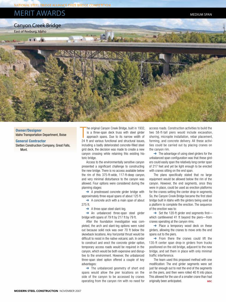
MerIt aWardScanyon creek Bridgeeast of rexburg, Idaho
The original Canyon Creek Bridge, built in 1932, is a three-span deck truss with steel girder approach spans. Due to its narrow width of
24 ft and various functional and structural issues, including a badly deteriorated concrete-filled steel grid deck, the decision was made to create a new canyon crossing while retaining this existing his-toric bridge.
Access to the environmentally sensitive canyon presented a significant challenge to constructing the new bridge. There is no access available below the rim of this 375-ft-wide, 117-ft-deep canyon, and very minimal disturbance to the canyon was allowed. Four options were considered during the planning stages:
A prestressed concrete girder bridge with ➜➜
approximately three equal spans of about 125 ft.A concrete arch with a main span of about ➜➜
275 ft.A three-span steel slant-leg.➜➜
An unbalanced three-span steel girder ➜➜
bridge with spans of 79 ft by 217 ft by 79 ft. After the foundation investigation was com-
pleted, the arch and slant-leg options were ruled out because solid rock was over 70 ft below the skewback locations. Any horizontal thrust would be difficult to resist in the native volcanic ash. In order to construct and erect the concrete girder option, temporary access roads would be required in the canyon, which would be both expensive and disrup-tive to the environment. However, the unbalanced three-span steel option offered a couple of key advantages:
The unbalanced geometry of short end ➜➜
spans would allow the pier locations on the side of the canyon to be accessed by cranes operating from the canyon rim with no need for
access roads. Construction activities to build the two 58-ft-tall piers would include excavation, shoring, micropile installation, rebar placement, forming, and concrete delivery. All these activi-ties could be carried out by placing cranes on the canyon rim.
The advantage of using steel girders for the ➜➜
unbalanced span configuration was that these gird-ers could easily span the relatively long center span of 217 feet and yet be light enough to be erected with cranes sitting on the end span.
The plans specifically stated that no large equipment would be allowed below the rim of the canyon. However, the end segments, once they were in place, could be used as erection platforms for the cranes setting the center drop-in segments. So, the Canyon Creek Bridge became the first steel bridge built in Idaho with the girders being used as a platform to complete the erection. The sequence of the erection was to:
Set the 120-ft girder end segments first—➜➜
which cantilevered 41 ft beyond the piers—from cranes operating at the canyon rims.
Place a temporary wood deck on these ➜➜
girders, allowing the cranes to move onto the end spans out to the piers.
From there the cranes could lift the ➜➜
135-ft center span drop-in girders from trucks positioned on the old bridge, adjacent to the new bridge, and set them in place with only minimal traffic interference.
The team used this proposed method with one modification: The end girder segments were set just far enough out to rest the end of the segments on the piers, and then were rolled 40 ft into place. This allowed for the use of a smaller crane than had originally been anticipated.
Owner/DesignerIdaho Transportation Department, Boise
General ContractorSletten Construction Company, Great Falls,
Mont.
MedIuM SPaN
MODERN STEEL CONSTRUCTION november 2007
MedIuM SPaN
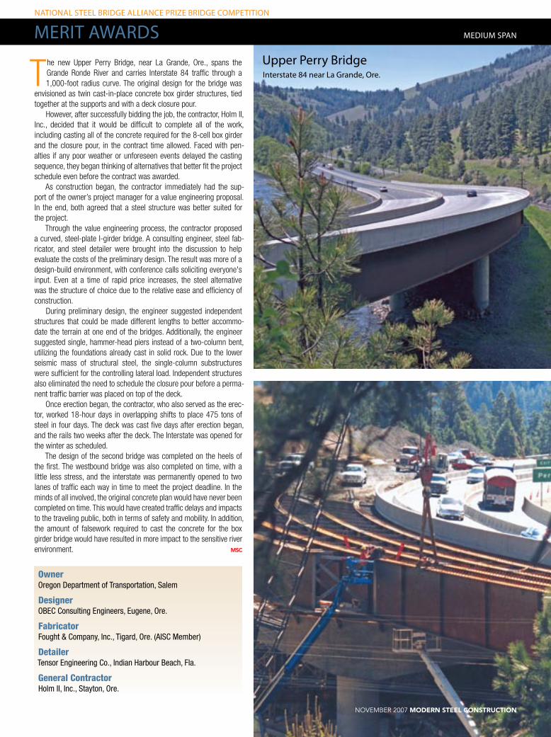
The new Upper Perry Bridge, near La Grande, Ore., spans the Grande Ronde River and carries Interstate 84 traffic through a 1,000-foot radius curve. The original design for the bridge was
envisioned as twin cast-in-place concrete box girder structures, tied together at the supports and with a deck closure pour.
However, after successfully bidding the job, the contractor, Holm II, Inc., decided that it would be difficult to complete all of the work, including casting all of the concrete required for the 8-cell box girder and the closure pour, in the contract time allowed. Faced with pen-alties if any poor weather or unforeseen events delayed the casting sequence, they began thinking of alternatives that better fit the project schedule even before the contract was awarded.
As construction began, the contractor immediately had the sup-port of the owner’s project manager for a value engineering proposal. In the end, both agreed that a steel structure was better suited for the project.
Through the value engineering process, the contractor proposed a curved, steel-plate I-girder bridge. A consulting engineer, steel fab-ricator, and steel detailer were brought into the discussion to help evaluate the costs of the preliminary design. The result was more of a design-build environment, with conference calls soliciting everyone's input. Even at a time of rapid price increases, the steel alternative was the structure of choice due to the relative ease and efficiency of construction.
During preliminary design, the engineer suggested independent structures that could be made different lengths to better accommo-date the terrain at one end of the bridges. Additionally, the engineer suggested single, hammer-head piers instead of a two-column bent, utilizing the foundations already cast in solid rock. Due to the lower seismic mass of structural steel, the single-column substructures were sufficient for the controlling lateral load. Independent structures also eliminated the need to schedule the closure pour before a perma-nent traffic barrier was placed on top of the deck.
Once erection began, the contractor, who also served as the erec-tor, worked 18-hour days in overlapping shifts to place 475 tons of steel in four days. The deck was cast five days after erection began, and the rails two weeks after the deck. The Interstate was opened for the winter as scheduled.
The design of the second bridge was completed on the heels of the first. The westbound bridge was also completed on time, with a little less stress, and the interstate was permanently opened to two lanes of traffic each way in time to meet the project deadline. In the minds of all involved, the original concrete plan would have never been completed on time. This would have created traffic delays and impacts to the traveling public, both in terms of safety and mobility. In addition, the amount of falsework required to cast the concrete for the box girder bridge would have resulted in more impact to the sensitive river environment.
OwnerOregon Department of Transportation, Salem
DesignerOBEC Consulting Engineers, Eugene, Ore.
FabricatorFought & Company, Inc., Tigard, Ore. (AISC Member)
DetailerTensor Engineering Co., Indian Harbour Beach, Fla.
General ContractorHolm II, Inc., Stayton, Ore.
upper Perry BridgeInterstate 84 near la grande, ore.
NatIoNal Steel BrIdge allIaNce PrIze BrIdge coMPetItIoN
MerIt aWardS
november 2007 MODERN STEEL CONSTRUCTION

NatIoNal Steel BrIdge allIaNce PrIze BrIdge coMPetItIoN
MerIt aWardS
Ravenna viaduct is located on Highway 68 at the southern edge of downtown Ravenna, Neb. and spans a major route of the Burling-
ton Northern Santa Fe Railroad. The original viaduct, built in 1937, was a five-span 265.5-ft.-long bridge with a 24-ft.-wide roadway and a 5-ft.-wide side-walk. Thanks to structural deficiency and functional obsolescence, it was replaced with a new 174-ft. single-span parallel tied arch viaduct with a 43-ft.-wide roadway and 8-ft.-wide sidewalk.
The parallel arch system offers a unique solution to the problem, providing a structural depth includ-ing slab of less than 35 in., and does not require the use of a pier. This slender arch system is only possible because of high-performance steel and concrete, as well as new theories recognizing the increased strength of confined concrete. The main structural components of the parallel arch system are: tie beams, arch pipes, floor beams, hangers, and deck. The system allows for a minimum struc-tural depth by using the tie beam as a tension tie and the arch pipes as a compression strut. In this way, the moment in the girder is reduced by this tie
beam/arch couple.The critical member is the tie beam. By using
a concrete-filled, post-tensioned beam, it was pos-sible to limit the beam depth to only 2 ft. The tie beams are 24-in. by 24-in. box beams fabricated from ½-in.-thick Grade 50W steel. Each beam is filled with 8-ksi high-strength concrete and post-tensioned with 38 fully tensioned 0.6-in.-diameter strands. The tie beam is the most innovative feature of the system. The post-tensioning eliminates the concern over fatigue by keeping the section in net compression during loading.
The arch is the primary compression member in the system. Each arch consists of two 12-in.-diam-eter, ½-in.-thick extra-strong, ASTM A 500, Grade C steel pipes. The pipes were bent to the proper radius prior to being delivered to the fabricator and are filled with 8-ksi high-strength concrete. There is no transverse bracing connecting the top chords. This is highly desirable for aesthetic reasons. The lack of transverse horizontal braces also provides unlimited overhead clearance. At their peak, the arches are 25 ft. above the roadway grade. The
independent arches were accomplished by placing the two concrete-filled pipes parallel to each other with one foot of space between them. This greatly increased the moment of inertia of the arch in the lateral direction, and provided an ideal space for the top connection of the hanger rods. High-strength 1¾-in. threaded rods serve has hangers. The rods extend from a bracket between the arch pipes and pass through the tie beam.
W24×250 Grade 50W wideflange floor beams connect the two tie beams. The floor beams are bolted to double angles, which are in turn bolted to the tie beam.
Owner/Designer/DetailerNebraska Department of Roads, Lincoln
FabricatorCapital Contractors, Inc., Lincoln (AISC
Member)
General ContractorChristensen Bros., Inc., Cherokee, Iowa
ravenna Viaductravenna, Neb.
MedIuM SPaN
MODERN STEEL CONSTRUCTION november 2007
recoNStructIoN
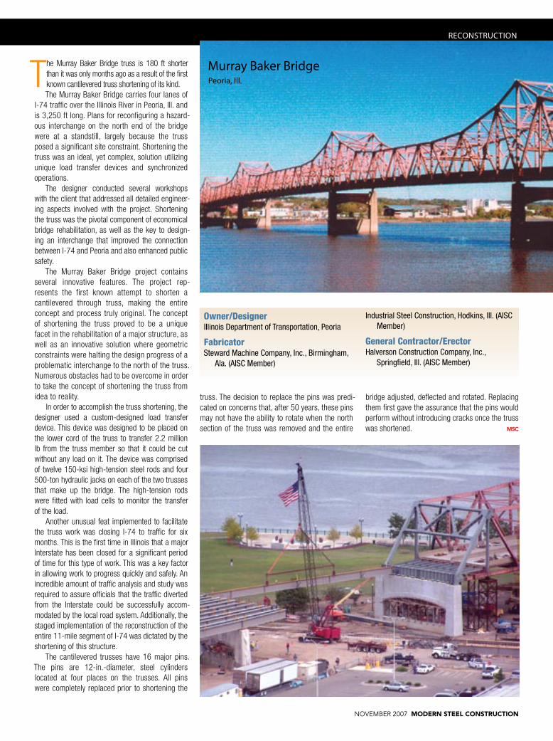
The Murray Baker Bridge truss is 180 ft shorter than it was only months ago as a result of the first known cantilevered truss shortening of its kind. The Murray Baker Bridge carries four lanes of
I-74 traffic over the Illinois River in Peoria, Ill. and is 3,250 ft long. Plans for reconfiguring a hazard-ous interchange on the north end of the bridge were at a standstill, largely because the truss posed a significant site constraint. Shortening the truss was an ideal, yet complex, solution utilizing unique load transfer devices and synchronized operations.
The designer conducted several workshops with the client that addressed all detailed engineer-ing aspects involved with the project. Shortening the truss was the pivotal component of economical bridge rehabilitation, as well as the key to design-ing an interchange that improved the connection between I-74 and Peoria and also enhanced public safety.
The Murray Baker Bridge project contains several innovative features. The project rep-resents the first known attempt to shorten a cantilevered through truss, making the entire concept and process truly original. The concept of shortening the truss proved to be a unique facet in the rehabilitation of a major structure, as well as an innovative solution where geometric constraints were halting the design progress of a problematic interchange to the north of the truss. Numerous obstacles had to be overcome in order to take the concept of shortening the truss from idea to reality.
In order to accomplish the truss shortening, the designer used a custom-designed load transfer device. This device was designed to be placed on the lower cord of the truss to transfer 2.2 million lb from the truss member so that it could be cut without any load on it. The device was comprised of twelve 150-ksi high-tension steel rods and four 500-ton hydraulic jacks on each of the two trusses that make up the bridge. The high-tension rods were fitted with load cells to monitor the transfer of the load.
Another unusual feat implemented to facilitate the truss work was closing I-74 to traffic for six months. This is the first time in Illinois that a major Interstate has been closed for a significant period of time for this type of work. This was a key factor in allowing work to progress quickly and safely. An incredible amount of traffic analysis and study was required to assure officials that the traffic diverted from the Interstate could be successfully accom-modated by the local road system. Additionally, the staged implementation of the reconstruction of the entire 11-mile segment of I-74 was dictated by the shortening of this structure.
The cantilevered trusses have 16 major pins. The pins are 12-in.-diameter, steel cylinders located at four places on the trusses. All pins were completely replaced prior to shortening the
Owner/DesignerIllinois Department of Transportation, Peoria
FabricatorSteward Machine Company, Inc., Birmingham,
Ala. (AISC Member)
Industrial Steel Construction, Hodkins, Ill. (AISC Member)
General Contractor/ErectorHalverson Construction Company, Inc.,
Springfield, Ill. (AISC Member)
Murray Baker BridgePeoria, Ill.
truss. The decision to replace the pins was predi-cated on concerns that, after 50 years, these pins may not have the ability to rotate when the north section of the truss was removed and the entire
bridge adjusted, deflected and rotated. Replacing them first gave the assurance that the pins would perform without introducing cracks once the truss was shortened.
november 2007 MODERN STEEL CONSTRUCTION
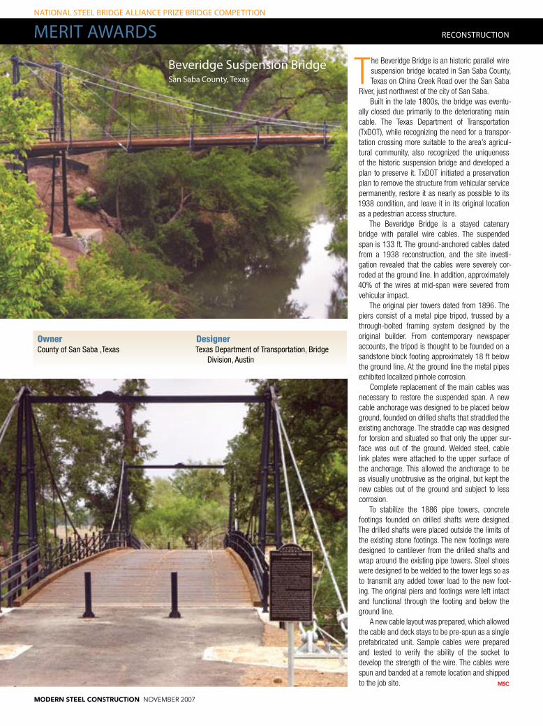
The Beveridge Bridge is an historic parallel wire suspension bridge located in San Saba County, Texas on China Creek Road over the San Saba
River, just northwest of the city of San Saba. Built in the late 1800s, the bridge was eventu-
ally closed due primarily to the deteriorating main cable. The Texas Department of Transportation (TxDOT), while recognizing the need for a transpor-tation crossing more suitable to the area’s agricul-tural community, also recognized the uniqueness of the historic suspension bridge and developed a plan to preserve it. TxDOT initiated a preservation plan to remove the structure from vehicular service permanently, restore it as nearly as possible to its 1938 condition, and leave it in its original location as a pedestrian access structure.
The Beveridge Bridge is a stayed catenary bridge with parallel wire cables. The suspended span is 133 ft. The ground-anchored cables dated from a 1938 reconstruction, and the site investi-gation revealed that the cables were severely cor-roded at the ground line. In addition, approximately 40% of the wires at mid-span were severed from vehicular impact.
The original pier towers dated from 1896. The piers consist of a metal pipe tripod, trussed by a through-bolted framing system designed by the original builder. From contemporary newspaper accounts, the tripod is thought to be founded on a sandstone block footing approximately 18 ft below the ground line. At the ground line the metal pipes exhibited localized pinhole corrosion.
Complete replacement of the main cables was necessary to restore the suspended span. A new cable anchorage was designed to be placed below ground, founded on drilled shafts that straddled the existing anchorage. The straddle cap was designed for torsion and situated so that only the upper sur-face was out of the ground. Welded steel, cable link plates were attached to the upper surface of the anchorage. This allowed the anchorage to be as visually unobtrusive as the original, but kept the new cables out of the ground and subject to less corrosion.
To stabilize the 1886 pipe towers, concrete footings founded on drilled shafts were designed. The drilled shafts were placed outside the limits of the existing stone footings. The new footings were designed to cantilever from the drilled shafts and wrap around the existing pipe towers. Steel shoes were designed to be welded to the tower legs so as to transmit any added tower load to the new foot-ing. The original piers and footings were left intact and functional through the footing and below the ground line.
A new cable layout was prepared, which allowed the cable and deck stays to be pre-spun as a single prefabricated unit. Sample cables were prepared and tested to verify the ability of the socket to develop the strength of the wire. The cables were spun and banded at a remote location and shipped to the job site.
OwnerCounty of San Saba ,Texas
DesignerTexas Department of Transportation, Bridge
Division, Austin
recoNStructIoN
NatIoNal Steel BrIdge allIaNce PrIze BrIdge coMPetItIoN
MerIt aWardS
Beveridge Suspension BridgeSan Saba county, texas
MODERN STEEL CONSTRUCTION november 2007

The 1960s-era, two-lane, precast concrete Wall Street Bridge—over the Red River of the North between Fargo, N.D. and Moorhead, Minn.—
was designed to overtop during major flood events. However, the lightweight, open steel middle span required frequent repairs, and residents complained of the noise it made when vehicles passed over it. County and state officials determined that the bridge was structurally, hydraulically, and geometrically defi-cient, and made the decision to replace it.
Continuous steel construction provides the geo-metric and span capabilities to complete the new crossing, maximizing clearance over potential flood elevations, while minimizing approach transitions as well as disturbance to the existing residential areas. The deck profile is a single vertical curve, centered about the middle of the channel. The 12-span con-tinuous steel beam structure, symmetrical about the center of the channel, is proportioned and sited at the original crossing location. Two continuous welded plate girder spans were used over the river,
and five continuous spans of rolled steel beams were used for the approaches. Hinged expansion joints separate the approach spans from the main river spans. Eight composite beam lines comprise the superstructure.
During construction, with approximately two-thirds of the beams set, the crossing experienced its third-greatest flood on record. With no interrup-tion to construction, residents and officials were reassured the new bridge would offer a safe cross-ing even through major flood events.
The 66-ft-wide bridge deck accommodates four lanes of traffic and a walkway/trail. As an interim measure, however, it is striped in a “super two” configuration—a two-lane roadway with center turn lanes.
Completed on schedule and within budget, the new 955-ft-long and 66-ft-wide Wall Street Bridge is comprised of 1,763,201 lb of structural steel; 22,375 ft of steel H-piling; 873,270 lb of reinforce-ment; and 62,928 sq. ft of bridge deck.
SHort SPaN
OwnerClay County Highway Department, Moorhead,
Minn.Cass County Highway Department, West Fargo,
N.D.
DesignerWidseth Smith Nolting & Assoc., Inc.,
Alexandria, Minn.
FabricatorRoscoe Steel & Culvert, Billings, Mont. (AISC
Member)
General ContractorIndustrial Builders, Inc., Fargo, N.D.
Wall Street BridgeFargo, N.d. / Moorhead, Minn.
november 2007 MODERN STEEL CONSTRUCTION
NatIoNal Steel BrIdge allIaNce PrIze BrIdge coMPetItIoN
MerIt aWardS
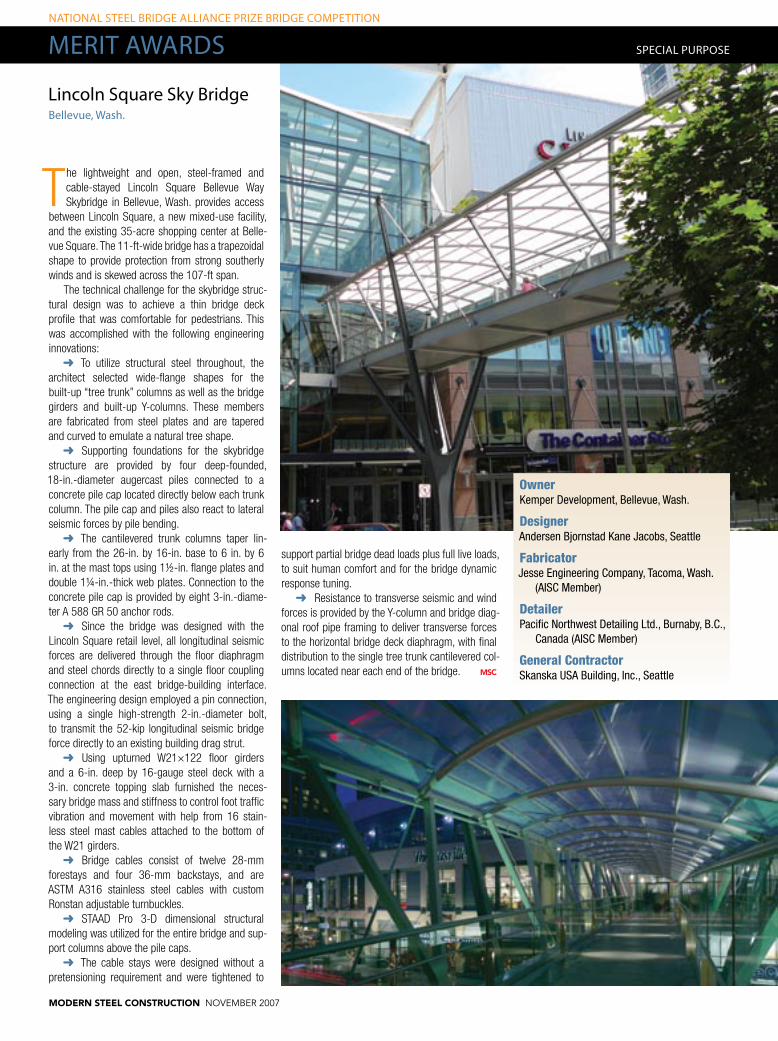
The lightweight and open, steel-framed and cable-stayed Lincoln Square Bellevue Way Skybridge in Bellevue, Wash. provides access
between Lincoln Square, a new mixed-use facility, and the existing 35-acre shopping center at Belle-vue Square. The 11-ft-wide bridge has a trapezoidal shape to provide protection from strong southerly winds and is skewed across the 107-ft span.
The technical challenge for the skybridge struc-tural design was to achieve a thin bridge deck profile that was comfortable for pedestrians. This was accomplished with the following engineering innovations:
To utilize structural steel throughout, the ➜➜
architect selected wide-flange shapes for the built-up “tree trunk” columns as well as the bridge girders and built-up Y-columns. These members are fabricated from steel plates and are tapered and curved to emulate a natural tree shape.
Supporting foundations for the skybridge ➜➜
structure are provided by four deep-founded, 18-in.-diameter augercast piles connected to a concrete pile cap located directly below each trunk column. The pile cap and piles also react to lateral seismic forces by pile bending.
The cantilevered trunk columns taper lin-➜➜
early from the 26-in. by 16-in. base to 6 in. by 6 in. at the mast tops using 1½-in. flange plates and double 1¼-in.-thick web plates. Connection to the concrete pile cap is provided by eight 3-in.-diame-ter A 588 GR 50 anchor rods.
Since the bridge was designed with the ➜➜
Lincoln Square retail level, all longitudinal seismic forces are delivered through the floor diaphragm and steel chords directly to a single floor coupling connection at the east bridge-building interface. The engineering design employed a pin connection, using a single high-strength 2-in.-diameter bolt, to transmit the 52-kip longitudinal seismic bridge force directly to an existing building drag strut.
Using upturned W21×122 floor girders ➜➜
and a 6-in. deep by 16-gauge steel deck with a 3-in. concrete topping slab furnished the neces-sary bridge mass and stiffness to control foot traffic vibration and movement with help from 16 stain-less steel mast cables attached to the bottom of the W21 girders.
Bridge cables consist of twelve 28-mm ➜➜
forestays and four 36-mm backstays, and are ASTM A316 stainless steel cables with custom Ronstan adjustable turnbuckles.
STAAD Pro 3-D dimensional structural ➜➜
modeling was utilized for the entire bridge and sup-port columns above the pile caps.
The cable stays were designed without a ➜➜
pretensioning requirement and were tightened to
lincoln Square Sky BridgeBellevue, Wash.
SPecIal PurPoSe
OwnerKemper Development, Bellevue, Wash.
DesignerAndersen Bjornstad Kane Jacobs, Seattle
FabricatorJesse Engineering Company, Tacoma, Wash.
(AISC Member)
DetailerPacific Northwest Detailing Ltd., Burnaby, B.C.,
Canada (AISC Member)
General ContractorSkanska USA Building, Inc., Seattle
support partial bridge dead loads plus full live loads, to suit human comfort and for the bridge dynamic response tuning.
Resistance to transverse seismic and wind ➜➜
forces is provided by the Y-column and bridge diag-onal roof pipe framing to deliver transverse forces to the horizontal bridge deck diaphragm, with final distribution to the single tree trunk cantilevered col-umns located near each end of the bridge.
MODERN STEEL CONSTRUCTION november 2007

When it came to designing the Springwater Trail Pedestrian Bridge in Portland, Ore., the engineer was tasked with closing the
gap in a regional mixed-use trail system located in a major metropolitan area. The key was to develop a unique cost-effective bridge crossing, taking into account the numerous project constraints. The project was highly complex and involved input from a variety of sources, including local neighborhood groups, numerous public agency partners, and other key stakeholders. A principal goal of the proj-ect from the outset was to design an attractive and visually appealing bridge that was also sensitive to the context of the local environment.
The final scheme resulted in an innovative tied through arch bridge on the boundary of two adja-cent cities, clear-spanning a major six-lane highway with 63,000 cars a day passing beneath.
Slender 18-in.-diameter pipe arch segments across the highway work together with the inno-vative deck system including steel edge pipes and post tensioning. The span/depth ratio of the arches is L/160, well above the normal range for arch bridges. The arches were fabricated in halves and were set in place on two consecutive nights. Using edge pipes with internal post-tensioning rods allowed use of radial steel bar suspenders. The radial stays allowed the use of a circular function arch, which is not typical. The arches are con-
nected with only two arch braces at one-third points (approximately 70-ft spacing), giving the arches an extremely clean and efficient look.
Post-tensioning (bearing) cables act as a tie for the arches during construction. The bearing cables also act as a tie for live load and serve as an alter-native method of erecting the segmental deck pan-els by sliding them into positions. This method is also applicable to more challenging crossings.
Conventional full-length post-tensioning is placed in the cast-in-place topping slab to stiffen the entire bridge and to provide deck bending resis-tance to asymmetrical loading on the structure. The cast-in-place portion of the deck is poured using the segmental deck panels as the form.
Steel edge pipes and rod suspenders com-prise the simple and elegant hanger system. The suspenders connect to “flying” steel floor beams cantilevered from the deck panels to provide the required path clearance. Connections to both the arch and floor beams are standard AISC clevises, opposite threads top and bottom to allow for adjust-ment of the deck gradeline during erection.
Finally, steel grating is used to span the gap between the edge pipe and the segmental deck. The protective fencing is placed in the plane of the sus-penders to open up the deck area, and the steel rail is cantilevered from the steel bar suspenders to create an enhanced and inviting look to the user.
OwnerCity of Portland Parks and Recreation,
Portland, Ore.
DesignerOBEC Consulting Engineers, Eugene, Ore.
Fabricator/DetailerFought & Company, Inc., Tigard, Ore. (AISC
Member)
General ContractorMowat Construction, Clackamas, Ore.
SPecIal PurPoSe
Springwater trail (Mcloughlin Blvd.) Pedestrian BridgePortland, ore.
november 2007 MODERN STEEL CONSTRUCTION