Embed Size (px)
Citation preview

National Fire Protection Association 1 Bat terymarch Park, Quincy, MA 02169-7471 Phone: 617-770-3000 • Fax: 617-770-0700 • www.nfpa.org
AGENDA
NEC Code-Making Panel 2
Report on Proposal Meeting
January 16 – 21, 2012
Hilton Head, SC
Item No. Subject 12-1 -1 Call to Order 12-1-2 Introduction of Members and Guests 12-1-3 Review of Meeting Procedures and Revision Schedule 12-1-4 Comments/Questions from Committee Members and/or Guests 12-1-5 Task Group Reports (if any) 12-1-6 Processing of Proposals 12-1-7 Fire Protection Research Foundation Requests 12-1-8 Old Business 12-1-9 New Business 12-1-10 Adjournment

Chair Report 11/23/2011
Log Proposal No. Code Reference Log Proposal No. Code Reference
1170a Entire Document2-1
921a Entire Document2-2
2754 100.Branch Circuit, Multiware2-3
2066 100.Continuous Load2-4
3315 100.Demand (New)2-5
3314 100.Demand Factor, Demand2-6
2635 100.Ground-Fault2-7
2495 100.Guest Room2-8
3350 100.Out of Parameter Circuit2-9
1317 100.Unifinished Basement2-10
1645 210.22-11
1663 210.22-12
128 210.4 Exception (New)2-13
118 210.4(B) Exception (New)2-14
852 210.4(B) Exception (New)2-15
1110 210.4(B) Exception (New)2-16
1176 210.4(B) Exception (New)2-17
2068 210.4(D)2-18
2735 210.4(D)2-19
2069 210.4(E) (New)2-20
3293a 210.5(B), 215.6, and 215.122-21
3143 210.5(C)2-22
3257 210.5(C)2-23
3400 210.5(C)2-24
3495 210.5(D)2-25
2919 210.62-26
2712 210.72-27
533 210.82-28
1063 210.82-29
1292 210.82-30
1646 210.82-31
2122 210.82-32
2517 210.8 (New)2-33
2518 210.8 (New)2-34
2520 210.82-35
1935 210.8(A) Exception to (5)2-36
120 210.8(A)(2)2-37
3386 210.8(A)(2) Exception to (2)2-38
2290 210.8(A)(6)2-39
367 210.8(A)(7)2-40
686 210.8(A)(7)2-41
1447 210.8(A)(7)2-42
2139 210.8(A)(7)2-43
3043 210.8(A)(7)2-44
3044 210.8(A)(7)2-45
1145 210.8(A)(9) (New)2-46
2564 210.8(A)(9) (New)2-47
1112 210.8(B) (New)2-48
1542 210.8(B)2-49
2725 210.8(B)2-50
3276 210.8(B)2-51
900 210.8(B) Exception No. 1 to (3)2-52
1936 210.8(B)(2)2-53
2670 210.8(B)(2)2-54
3045 210.8(B)(5)2-55
2282 210.8(B)(8)2-56
2096 210.8(D) (New)2-57
2561 210.8(D)2-58
2636 210.8(D) (New)2-59
3345 210.9 Exception No. 3 (New)2-60
3397 210.11(C)(1), (2), and (3)2-61
524 210.11(C)(2)2-62
1504 210.11(C)(4)2-63
3398 210.11(C)(4) (New)2-64
19 210.122-65
20 210.122-66
21 210.122-67
22 210.122-68
23 210.122-69
24 210.122-70
25 210.122-71
26 210.122-72
27 210.122-73
28 210.122-74
29 210.122-75
687 210.122-76
2097 210.122-77
2293 210.122-78
2521 210.122-79
2563 210.122-80
3362 210.122-81
3337 210.12 Exception No. 1 (New)2-82
594 210.12(A)2-83
684 210.12(A)2-84
685 210.12(A)2-85
912 210.12(A)2-86
2098 210.12(A)2-87
2099 210.12(A)2-88
1

Chair Report 11/23/2011
Log Proposal No. Code Reference Log Proposal No. Code Reference
2120 210.12(A)2-89
2562 210.12(A)2-90
2723 210.12(A)2-91
3489 210.12(A)2-92
2638 210.12(A), Informational Note2-93
1543 210.12(A), Informational Note 22-94
2288 210.12(A), Informational Note 22-95
2093 210.12(A), Informational Note 42-96
2732 210.12(A) Exception (New)2-97
1288 210.12(A) Exception No. 1 and2-98
1463 210.12(A) Exception No. 1 and2-99
1493 210.12(A) Exception No. 1 and2-100
1634 210.12(A) Exception No. 12-101
3046 210.12(A) Exception No. 12-102
1508 210.12(A) Exception No. 22-103
1635 210.12(A) Exception No. 22-104
2034 210.12(A) Exception No. 22-105
2375 210.12(A) Exception No. 22-106
2378 210.12(A) Exception No. 22-107
2381 210.12(A) Exception No. 22-108
3047 210.12(A) Exception No. 32-109
3435 210.12(A) Exception No. 42-110
30 210.12(B)2-111
31 210.12(B)2-112
32 210.12(B)2-113
33 210.12(B)2-114
536 210.12(B)2-115
2111 210.12(B) (New)2-116
34 210.12(B) Exception No. 12-117
35 210.12(B) Exception No. 12-118
3436 210.12(B) Exception No. 12-119
140 210.12(B) Exception No. 32-120
3048 210.12(B)(1)2-121
1464 210.12(B)(2)2-122
1636 210.12(B)(2)2-123
1647 210.12(B)(2)2-124
1789 210.13 (New)2-125
2513 210.132-126
3351 210.13 (New)2-127
3484 210.132-128
1081 210.182-129
2496 210.182-130
2251 210.19(A)(1)2-131
1871 210.19(A)(1), Informational2-132
1700 210.19(A)(2)2-133
117 210.19(A)(5) (New)2-134
129 210.19(A)(5)2-135
2305 210.19(A)(5)2-136
1544 210.21(B)2-137
2325 Table 210.21(B)(3)2-138
3010 210.22 (New)2-139
2705 210.23 and 550.252-140
3011 210.232-141
1312 210.25(A)2-142
1113 210.502-143
149 210.522-144
1378 210.52(b)(3)2-145
253 210.52, Informational Note2-146
2688 210.52(A)2-147
3049 210.52(A)2-148
1509 210.52(A)(1)2-149
1311 210.52(A)(2)(3)2-150
1313 210.52(A)(2)(3)2-151
2672 210.52(A)(2) and (3)2-152
2734 210.52(A)(2) Exception (New)2-153
1167 210.52(A)(3)2-154
1790 210.52(B)(1)2-155
1890 210.52(B)(1)2-156
1772 210.52(B)(3)2-157
1891 210.52(B)(3)2-158
1892 210.52(C)2-159
2299 210.52(C)(2)2-160
2673 210.52(C)(2)2-161
2674 210.52(C)(3)2-162
2295 210.52(C)(4)2-163
3387 210.52(C)(5)2-164
688 210.52(C)(5) Exception2-165
121 210.52(D)2-166
131 210.52(D)2-167
1545 210.52(E)2-168
1546 210.52(E)2-169
3050 210.52(E)2-170
3260 210.52(E)2-171
3261 210.52(E)(1)2-172
186 210.52(E)(2)2-173
3262 210.52(E)(2)2-174
825 210.52(E)(3)2-175
2710 210.52(E)(3)2-176
2

Chair Report 11/23/2011
Log Proposal No. Code Reference Log Proposal No. Code Reference
525 210.52(F)2-177
1547 210.52(F) Exception No. 12-178
2260 210.52(G)2-179
3263 210.52(G)2-180
1505 210.52(G)(1)2-181
3399 210.52(G)(3) (New)2-182
1506 210.52(H)2-183
2278 210.52(H)2-184
3051 210.52(I)2-185
1507 210.52(J) (New)2-186
1154 210.622-187
2062 210.632-188
2112 210.632-189
2726 210.632-190
1111 210.64 (New)2-191
2519 210.702-192
3264 210.702-193
375 210.70(3)2-194
1401 210.70(A)(1)2-195
3492 210.70(A)(1)2-196
1876 210.70(A)(2)(b)2-197
1140 210.70(C)2-198
1142 210.89(B)(9) (New)2-199
2681 210.1192-200
2252 215.2(A)(1)2-201
3052 215.2(A)(1) Exception No. 22-202
2340 215.2(A)(1) Exception No. 32-203
1147 215.2(A)(2)2-204
526 215.2(A)(4)2-205
529 215.2(A)(4)2-206
2091 215.2(A)(4)2-207
2279 215.2(A)(4)2-208
2700 215.2(A)(4)2-209
2934 215.2(A)(4)2-210
3176 215.2(A)(4)2-211
1662 215.2(A)(5) (New)2-212
1701 215.2(A)(5)2-213
2339 215.3 Exception (New)2-214
1791 215.92-215
2637 215.92-216
3258 215.12(C)2-217
812 2202-218
925 Table 220.32-219
2150 220.6 (New)2-220
2165 220.6 (New)2-221
2238 220.6 (New)2-222
2904 220.6 (New)2-223
2909 220.10 Exception and 220.402-224
102 220.122-225
1460 Table 220.122-226
1758 Table 220.122-227
2914 220.12 Exception2-228
98 220.12(J) and 220.12(J)(1)2-229
924 220.142-230
1759 220.142-231
2752 220.14(B)2-232
3316 220.14(C)2-233
247 220.14(F)2-234
1757 220.16(C) (New)2-235
1842 220.40, Informational Note2-236
400 220.42, 220.44, 220.54,2-237
2277 Table 220.422-238
2751 220.502-239
701 220.52(C)2-240
808 220.52(C) (New)2-241
3402 220.53 Exception (New)2-242
1177 Table 220.552-243
2280 Table 220.552-244
2753 220.552-245
3494 Table 220.552-246
1773 220.58 (New)2-247
1774 220.82(A)2-248
1800 220.84(D) (New)2-249
1801 220.84(D)2-250
187 220.862-251
1173 220.86 (New)2-252
1354 220.86 (New)2-253
1918 220.86 (New)2-254
2239 220.862-255
2903 220.862-256
3317 220.872-257
2907 220.89 (New)2-258
1937 220.102(B) and Table2-259
1938 220.1032-260
1786 220.104 (New)2-261
2272 Annex D2-262
3500 Annex D2-263
3132 Example D.3(a)2-264
3

Chair Report 11/23/2011
Log Proposal No. Code Reference Log Proposal No. Code Reference
1302 Example D.4(b)2-265
1303 Example D.5(a)2-266
1304 Example D.5(a)2-267
1305 Example D.5(b)2-268
4

Report on Proposals – June 2013 NFPA 70_______________________________________________________________________________________________2-1 Log #1170a NEC-P02
_______________________________________________________________________________________________Russell LeBlanc, The Peterson School
In articles 90 through 830, if the wording is not already there, then add the words (or otherstructure(s)) after the word BUILDING(S) wherever the intent of the requirement is to also include STRUCTURES aswell as buildings.
There is a flaw in the NEC. The term "building" is used over 1000 times in the NEC, and in most of thecases the words "or other structure" should follow and apply the same requirements to bridges, billboards, towers,tanks, and other structures that are by definition NOT BUILDINGS. One specific example I can use is section 225.10Wiring onBuildings. I believe that this section is also intended to be applied structures, but the wording "or other structures" is notin the heading or the paragraph. There are literally thousands of other instances throughout the code that this sameproblem exists. This can easily be seen by doing an electronic search for the word "building". In some cases the words"or other structure" (or similar wording) are present, but in the vast majority where the requirements should also beapplied to structures other than buildings, the wording is not there.
_______________________________________________________________________________________________2-2 Log #921a NEC-P02
_______________________________________________________________________________________________Joe Tedesco, Boston, MA
The term "adequate" and "adequately" and "inadequately" and "inadequate" should be replacedwith terms that can be properly enforced and understood.
Terms are not defined and are considered vague and unenforceable per Table 3.2.1 in the NEC StyleManaual. They are all "incorrect" 148 times in the NEC.
_______________________________________________________________________________________________2-3 Log #2754 NEC-P02
_______________________________________________________________________________________________James F. Williams, Fairmont, WV
Revise text to read as follows:A branch circuit that consists of two or more ungrounded conductors that have a
voltage between them, and a grounded conductor that has a nominal equal voltage between it and each ungroundedconductor of the circuit and that is connected to the neutral or grounded conductor of the system.
The original definition would not cover a delta circuit with one side’s center tap grounded.
_______________________________________________________________________________________________2-4 Log #2066 NEC-P02
_______________________________________________________________________________________________Michael L. Last, Naalehu, HI
Revise text as follows:Continuous Load – A load where the maximum current is expected has the ability (i.e. likelihood or possibility) to
continue for 3 hours or more during normal operation.The term ‘expected’ is vague and imprecise. Consider an electric storage water heater with resistive
electric element(s). It is expected that the element(s) will cycle on and off in response to the thermostat. However, theelement(s) have the ability to remain energized continuously during normal operation. While not normally expected tooccur, this action would not be attributed to any component failure, but to extended periods of high continuous hot waterusage. This scenario is not restricted to water heaters; it could occur with other electric loads; range, water well pumps,etc. This proposal will clarify the definition of “Continuous Load”.
1Printed on 11/23/2011

Report on Proposals – June 2013 NFPA 70_______________________________________________________________________________________________2-5 Log #3315 NEC-P02
_______________________________________________________________________________________________James E. Degnan, Sparling
Add new text to read as follows:Demand. An electrical load that is less than the connected load as a result of operational or other factors.
The definition of Demand Factor shortchanges the reader in that it literally states: demand factor=maximum demand/connected load. A more technically correct presentation is “demand factor =maximum demandload/connected load. By defining “demand” as “demand load” the ratio clearly becomes dimensionless.
_______________________________________________________________________________________________2-6 Log #3314 NEC-P02
_______________________________________________________________________________________________James E. Degnan, Sparling
Revise text to read as follows:Demand Factor. The ratio of the maximum demand load of a system or part of a system, to the total connected load of
a system or part of a system under consideration.Demand Load. An electrical load that is less than the connected load as a result of operational or other factors.
It is necessary to add a definition of Demand Load, as none exists in the NEC. The NEC presentlydefines demand factor using “demand” but this leaves the reader without direction because “demand” is undefined. Atpresent the definition of Demand Factor literally states that the demand factor =maximum demand/connected load. Amore technically correct presentation is “demand factor =maximum demand load/connected load. By adding the word“load” the demand factor ratio clearly becomes dimensionless.Note that if accepted this definition should be evaluated and applied elsewhere in the NEC where the word “demand”
would need to change to “demand load”, such as 220.87.(This is an alternative to the “Demand” definition proposal I submitted)
2Printed on 11/23/2011

Report on Proposals – June 2013 NFPA 70_______________________________________________________________________________________________2-7 Log #2635 NEC-P02
_______________________________________________________________________________________________Paul S. Hamer, Chevron Energy Technology Company
Add new text to read as follows:A system intended to provide personnel
protection from line-to-ground fault currents on three-phase systems, which selectively operates to cause adisconnecting means to open all ungrounded conductors of the faulted feeder or branch circuit within an establishedperiod of time when the sensed fault current to ground exceeds 6 mA.Informational Note No. 1: On three-phase systems that exceed 150 volts to ground, the capacitive-charging current of
a non-faulted individual feeder or branch circuit (a current that is also sensed during a system ground fault) can exceedthe 6 mA current threshold for circuits of normal length. The GFCIS-3Ph discriminates between the capacitive chargingcurrent of the “healthy” three-phase feeder or branch circuits during a ground fault, and the genuine ground-fault currenton the faulted feeder or branch circuit.Informational Note No. 2: The GFCIS-3Ph may also be used to selectively detect and isolate incipient insulation failure
of electrical equipment connected to three-phase feeder or branch circuits.A new definition is required to accompany companion proposals also submitted by me for the
GFCIS-3Ph in Articles 210.8(D) and 215.9. See those proposals for details of the system. There is no present NRTLstandard for GFCI devices applied above 125 volts to ground; hence the pickup level of 6 mA is designated in theproposed definition. It is expected that a new NRTL (e.g., Underwriters Laboratories) standard will be developed for theGFCIS-3Ph that will establish the required opening time of the disconnecting means of the system, expected to be ainverse-time characteristic between 6 mA and approximately 30 mA, and a definite time (between 0.025 and 0.10second, depending on the application) for sensed ground-fault currents that exceed 30 mA.Informational Note No. 1 is proposed to provide information on how the system functions. Informational No. 2 is
proposed to describe an alternate use of the system beyond the primary use for personnel protection.The basis of this proposal and the associated proposals is “A ground-fault circuit-interrupter method and system for
three-phase electrical power systems,” for which a U.S. Patent No. 7,301,739 (copy in supporting material) has beengranted and a proof-of-concept system has been fabricated and tested. Refer to my proposal for 210.8(D) for details ofhow the system operates and the problem it addresses. Chevron U.S.A., Inc. is the assignee of the patent. If thisproposal is accepted for inclusion in the NEC, Chevron U.S.A., Inc. will comply with the NFPA and ANSI Patent Policy;specifically, one of the following:a) A license will be made available without compensation to the applicants desiring to utilize the license for the purpose
of implementing the standard; orb) A license will be made available to applicants under reasonable terms and conditions that are demonstrably free of
any unfair discrimination.
3Printed on 11/23/2011

Report on Proposals – June 2013 NFPA 70_______________________________________________________________________________________________2-8 Log #2495 NEC-P02
_______________________________________________________________________________________________Errol C. Stone, Blank, Wesselink, Cook & Associates, Inc.
Revise text to read as follows:An accommodation combining living, sleeping, sanitary, and storage facilities within a compartment, which may include
countertop cooking appliance.A bedroom or sleeping unit contains individuals who are vulnerable to injury or death due to fire,
smoke inhalation, etc. The bedroom is used as a criterion for the application of 210.12(A). Adding a definition of theword bedroom would better serve the AHJ in enforcing the requirements of 210.12(A) in facilities and living areaswithout permanent provision for cooking. The word "bedroom" is mentioned six times in the Handbook edition, but nodefinition in Article 100. A hotel room could be classified as a dwelling unit if there is a permanent provision for cooking.IBC Section 1102.1 Definitions "Intended to be occupied as a residence. This refers to a dwelling unit or sleeping unit
that can or will be used all or part of the time as the occupant's place of abode."IBC Section 202 defines a sleeping unit "as a room or space in which people sleep, which can also include permanent
provisions for living, eating, and either sanitation or kitchen facilities but not both. An example would be a studioapartment with a kitchenette (i.e., microwave, sink and refrigerator). Since the cooking arrangement is not permanent,this configuration would be considered a sleeping unit."The Life Safety Code has long recognized, sleeping/bedroom units are places where people stay for 1/3 of their lives
while sleeping. This is a key criterion in the application of AFCI protection to prevent Architects, Owners, Developers,Builders and Contractors from placing the cost of construction over the importance of the life safety of their residents byusing the intended or unintended exception not to install AFCI protection because each single unit lacks the permanentprovision for cooking.An accommodation combining living, sleeping, sanitary, and storage facilities within a compartment should meet the
requirement to have AFCI protection and prevent Architects, Owners, Developers, Builders and Contractors from usingthe intended or unintended exception within Article 201.12(A) requiring a permanent provision for cooking for a place forsleeping in a retirement facility. These sleeping units are similar to and function as dwelling units.A Supportive Living Facility contains multiple single units, providing complete and independent living for one person,
including permanent provisions for living, sleeping and sanitation. These single units are very similar to the definition ofa "dwelling unit" except for the permanent provision for cooking and by definition the single units would be classified as"Sleeping Units." Seniors living in these Supportive Living Facility should be afforded the same life safety protection asother seniors living in a single unit with permanent provisions for cooking.
_______________________________________________________________________________________________2-9 Log #3350 NEC-P02
_______________________________________________________________________________________________Steven R. Montgomery, 2D2C Inc.
Add new text to read as follows:Equipment incorporating means to detect certain
out of parameter conditions of supply voltage and load current and mitigate, by circuit interruption, the effects of (a)overload within utilization equipment; and (b) over- or under-voltage, that can pose a risk of fire ignition under certainconditions.
A definition of an Out of Parameter Circuit Interrupter - Voltage/Current (OPCI-VI) is needed todescribe this fire prevention technology presently manufactured by multiple suppliers and under consideration foradoption in several places elsewhere in NFPA 70.Note that sister proposals have been submitted as a new 210.13 and 406.3(D).Staff Note: This proposal has also been sent to Code-Making Panel 18 for review and action.
4Printed on 11/23/2011

Report on Proposals – June 2013 NFPA 70_______________________________________________________________________________________________2-10 Log #1317 NEC-P02
_______________________________________________________________________________________________James F. Williams, Fairmont, WV
Revise text to read as follows:Portions or areas of the basement not intended as habitable rooms and limited to
storage areas, work areas, and the like.(5) Unfinished basements — for purposes of this section, unfinished basements are defined as portions or
areas of the basement not intended as habitable rooms and limited to storage areas, work areas, and the like.The defined term is referenced in several articles of the NEC: (5), , (1),
, & .In general, Article 100 shall contain definitions of terms that appear in two or
more other articles of the .
_______________________________________________________________________________________________2-11 Log #1645 NEC-P02
_______________________________________________________________________________________________Charles Palmieri, Cohasset, MA
Relocate and renumber the existing language of 210.2 and install the following definition. NewDefinition as 210.02 Definitions.Modifications (Circuits). For the purpose of this article the term modifications shall include changes to an existingstructures branch circuit wiring installation, which results in the replacement, relocation or extension for the purpose ofserving outlets or utilization equipment. The term modifications in this section shall not apply to short sections of splicedconductors consistent with panelboard, device or luminaries replacement.
I am suggesting the relocation and renumbering of the exiting text of 210.2 to comply with the 2011NEC Style Manual Section 2.2.2.2, which reads “ Definitions in Other Articles. If an article contains one or moredefinitions, the definition(s) shall be in the second section, shall be listed in alphabetical order, and shall be styled asshown in the following examples”.There is conflict in the industry when applying the 2011 language located in 210.12(B). It would be helpful to have a
definition that is enforceable and understandable to installers, designers and inspectors. The current language of the2011 Code does not require the addition of AFCI protection for panelboard replacement or service upgrades but thisissue remains a point of debate amongst various enforcement jurisdictions. Acceptance of this proposal will clearlyindicate that the language of 210.12 (B) does not apply to panelboard replacements. Additionally my concern is focusedtowards the language in that section, which requires AFCI protection for circuit extensions and modifications. The termmodification does not appear to have a universally accepted definition in the field. Some are applying the wordmodification to all maintenance functions as well as extensions of the existing wiring methods. For example! Someconsider the installation or addition of short lengths of conductors (pigtails) within lighting outlet enclosures or switchenclosures when replacing switches and luminaires as an extension or modification of the circuit wiring. Is it the intentof this Code Panel to consider such minor extensions or repairs as the trigger to require the installation of AFCI’s?Clearly 406.4 (D) (4) of the 2014 edition will compel AFCI protection to be provided upon a receptacle replacement butthat language addresses device replacement and is not concerned with the aforementioned short lengths of conductors.Furthermore at this time Code Panel 9 does not provide a similar AFCI requirement for the replacement of switches inarticle 404 nor is there such mandatory language in article 410 for luminaries. Installers are continuingly instructed toinstall AFCI protection on circuitry when the scope of their work clearly does not extend or modify the existing circuitry.The proposed definition would provide some consistency in applying the 2011 language of 210.12 (B). Note that onedictionary defines a modification in part as such; “make basic or fundamental changes in order to give a new orientationto or to serve a new end “. Basic maintenance functions do not necessarily re-orientate nor serve a new end of theexisting circuitry. In any case it would be desirable to have a definition of these terms that is functional within the useand enforcement of the Code.
5Printed on 11/23/2011

Report on Proposals – June 2013 NFPA 70_______________________________________________________________________________________________2-12 Log #1663 NEC-P02
_______________________________________________________________________________________________James F. Williams, Fairmont, WV
Revise text to read as follows:
Branch circuits shall comply with this article and also with the applicable provisions of other articles of this . Theprovisions for branch circuits supplying equipment listed in Table 210.2 amend or supplement the provisions in thisarticle and shall apply to branch circuits referred to therein.
Remove archaic language.NEC style manual: 3.3.4 Word Clarity. Words and terms used in the shall be specific and clear in meaning, and
shall avoid jargon, trade terminology, industry-specific terms, or colloquial language that is difficult to understand.language shall be brief, clear, and emphatic. The following are examples of old-fashioned expressions and word usesthat shall not be permitted: "...herein...".
_______________________________________________________________________________________________2-13 Log #128 NEC-P02
_______________________________________________________________________________________________Dennis Alwon, Alwon Electric Inc.
Add new text to read as follows:210.4(B) Disconnecting MeansException: Where a multiwire branch circuit with line to neutral loads must be used at a separate structure in order to
comply with 225.30, and an alarm circuit is required for its safe operation is part of this multiwire branch circuit.The definition of structure is that which is built or constructed. A post in the ground would meet this
definition. Since a post is often used to install the alarm box for septic pumps and sewer lift pumps it is not possible towire them without violating one of 2 codes. As the code is now we can either run 2 individual branch circuits andviolate 225.30 or we use a multi-wire branch circuit and violate 210.4.(B) or 240.15(B)(1). The Dp breaker or handle tieson a muti-wire branch circuit would turn the alarm circuit off if there were a fault in the pump circuit. This would defeatthe purpose of 2 circuits. This exception would alleviate that problem.
_______________________________________________________________________________________________2-14 Log #118 NEC-P02
_______________________________________________________________________________________________Dennis Alwon, Alwon Electric Inc.
Add text to read as follows:210.4(B) Disconnecting MeansException: Where a multiwire branch circuit with line to neutral loads must be used at a separate structure in order to
comply with 225.30, and an alarm circuit is required for its safe operation is part of this multiwire branch circuit.The definition of structure is that which is built or constructed. A post in the ground would meet this
definition. Since a post is often used to install the alarm box for septic pumps and sewer lift pumps it is not possible towire them without violating one of two codes. As the code is now, we can either run two individual branch circuits andviolate 225.30 or we use a multi-wire branch circuit (MWBC) and violate 210.4(B) or 240.15(B)(1). The Dp breaker orhandle ties on a multi-wire branch circuit would turn the alarm circuit off if there were a fault in the pump circuit. Thiswould defeat the purpose of 2 circuits. This exception would alleviate that problem.
6Printed on 11/23/2011

Report on Proposals – June 2013 NFPA 70_______________________________________________________________________________________________2-15 Log #852 NEC-P02
_______________________________________________________________________________________________James Tente, City of Naperville
Add new Exception to read as follows:Exception: For existing branch-circuit installations only, such multi-wire circuits shall not be required to comply with the
simultaneous disconnecting means.Current language makes reconfiguring existing circuits to install controls, relays, contactors and
transfer switches impossible without completely rewiring the existing circuits, i.e., installing a transfer switch and panelboard newly fed by an optional standby system added to an existing system. Selected branch circuits moved over to thestandby panel would need to be completely rewired as simultaneous disconnecting of ungrounded conductors in themulti-wire would be impossible. The same problem would be evident if moving selected branch circuits over to acontactor controlled panel board.
_______________________________________________________________________________________________2-16 Log #1110 NEC-P02
_______________________________________________________________________________________________Tim Nyberg, Vine Industries
Add new text to read as follows:Exception: For existing branch-circuit installations only, shall not be required to comply with the simultaneous
disconnecting means.Current language makes reconfiguring existing circuits to install controls, relays, contactors and
transfer switches impossible without completely rewiring the existing circuits, i.e. installing a transfer switch and panelboard newly fed by an optional standby system added to an existing system. Selected branch circuits moved over to thestandby panel would need to be completely rewired as simultaneous disconnecting of ungrounded conductors in themulti-wire circuit would be impossible.
_______________________________________________________________________________________________2-17 Log #1176 NEC-P02
_______________________________________________________________________________________________Gary Nyberg, Vine Electric
Add new text to read as follows:210.4(B) Exception: For existing branch-circuit installations only, shall not be required to comply with the simultaneous
disconnecting means.Current language makes reconfiguring existing circuits to install controls, relays, contactors and
transfer switches impossible without completely rewiring the existing circuits, i.e., installing a transfer switch and panelboard newly fed by an optional standby system added to an existing system. Selected branch circuits moved over to thestandby panel would need to be completely rewired as simultaneous disconnecting of ungrounded conductors in themulti-wire circuit would be impossible.
7Printed on 11/23/2011

Report on Proposals – June 2013 NFPA 70_______________________________________________________________________________________________2-18 Log #2068 NEC-P02
_______________________________________________________________________________________________Michael L. Last, Naalehu, HI
Revise text as follows:(D) Grouping. The ungrounded and grounded circuit conductors of each multiwire branch circuit shall be grouped by
cable ties or similar means and identified as such in at least one location within the panelboard or other point oforigination. The means of identification shall be permanent by tagging or similar methods.
Three (or more) conductors bundled within a panelboard is not indicative that the conductors sobundled constitute a multiwire branch circuit. It is not unusual for numerous circuit conductors to be grouped perdiscretion of the installing party. The requirement of grouping all conductors of each multiwire branch circuit WITHOUT(further) IDENTIFICATION could lead to the negating of the intent of existing 210.4(D). With identification of a group ofconductors marked, ”multiwire branch circuit”, it would quickly and definitively establish that the conductors so bundledconstitute the reason for grouping; and lacking such identification, other bundles of conductors would indicate that theconductors were grouped for some other purpose.
_______________________________________________________________________________________________2-19 Log #2735 NEC-P02
_______________________________________________________________________________________________Robert Meier, Norwood, NJ
Add text to read as follows:The ungrounded and grounded circuit conductors of each multiwire branch circuit shall be
grouped by cable ties or similar means in at least one location with the panelboard or other point of origination.
Conductors in commercial and industrial occupancies are often installed with numeric wire markers oneach individual conductor (typically adjacent to the circuit breaker and neutral bar). Although the current coderequirement is adequate this system is superior tot he use of tape or wire tie bundling since those methods are oftenobscured by other conductors in a crowded panelboard gutter space. By installing the wire marker near the terminationpoint its corresponding multi-wire branch circuit numbers will be readily evident.
8Printed on 11/23/2011

Report on Proposals – June 2013 NFPA 70_______________________________________________________________________________________________2-20 Log #2069 NEC-P02
_______________________________________________________________________________________________Michael L. Last, Naalehu, HI
Add text as follows:(E) Identification of Ungrounded and Associated Grounded Conductors. At the locations indicated in 210.4(D), and at
all other locations where it is possible to interrupt the integrity of the grounded (neutral) conductor of a multiwire branchcircuit, all the ungrounded (phase or line) and grounded circuit conductors of each multiwire branch circuit shall beindividually grouped by cable ties or similar means and identified as such. At all locations where more than one multiwirebranch circuit is present, each separate multiwire branch circuit shall be uniquely identified whereby each groundedconductor is readily identified with the corresponding ungrounded conductors of that particular multiwire branch circuit.The means of identification shall be permanent by tagging or similar methods.
Multiwire branch circuits are unique in that when the integrity of the grounded (neutral) conductor iscompromised, a serious voltage imbalance can occur. The effect of such imbalance can place the safety of theindividual(s) performing work on said multiwire branch circuit at risk. The possibility exists also for detrimentalconsequences to equipment connected to the multiwire branch circuit. Similarly, when an ungrounded (phase or line)conductor of a multiwire branch circuit is disconnected and reconnected to a different phase (line), there exists thepotential for the grounded conductor of this multiwire branch circuit to operate at a current value that exceeds itsampacity. Where all the grounded and ungrounded conductors of a multiwire branch circuit are contained within a cableassembly, it could be readily indicated which are the associated conductors; however, when the conductors of amultiwire branch circuit(s) are not part of a cable assembly-such identification is not readily apparent. The concern forthe integrity of the grounded conductor is apparent in 300.13(B). Similar concern should be addressed at all points of amultiwire branch circuit, not just where devices connections are present. To stipulate that only qualified personnel wouldperform work on multiwire branch circuits, and, therefore, be cognizant of the associated hazards (i.e. voltage imbalanceand grounded conductor ampacity) is to rely on a false premise. When an electrical professional encounters a multitudeof conductors of varying colors, along with the need to perform the task in a timely manner, safety is not alwaysparamount. This proposal will increase the level of safety by making the worker immediately aware of the multiwirebranch circuit characteristics.
9Printed on 11/23/2011
Report on Proposals – June 2013 NFPA 70_______________________________________________________________________________________________2-21 Log #3293a NEC-P02
_______________________________________________________________________________________________Elliot Rappaport, Coconut Creek, FL
Replace the phrase “equipment grounding conductor” with the phrase “equipment bondingconductor” in the Articles and Sections as identified below. Replacement of “grounding” or “ground” when usedseparately is covered in separate proposals.
: 210.5(B) Title; 210.5(B) Exc. No. 2 to (4);: 215.6 Title; 215.6 (3x); 215.12(B) Title; 215.12
This proposal is one of a series of proposals to replace, throughout the Code, the term “grounding”with “bonding” where appropriate.As used in the Code, “grounding” is a well defined term and refers to connecting to the earth or ground for any one of a
number of reasons. Similarly, “bonding” is the connection of two bodies together to form a continuous electrical path.The term “equipment grounding conductor” has a definite purpose that is not uniquely expressed in the term. As aresult, there is a misconception that “grounding” will make a system safe. On the contrary, connecting equipment toground without providing the bonding connection back to the source can make the equipment less safe.The purpose of the “equipment grounding conductor (EGC) is to provide a low impedance path from a fault at
equipment “likely to become energized” to the source of the electrical current (transformer, generator, etc,). If it isargued that the purpose is to connect the equipment to ground, then the requirement of 250.4(A)(5) that “the earth shallnot be considered as an effective ground fault path” would no longer be valid because fault current would then beintended to flow to the ground (earth).From the conductor sizing requirements of 250.122, and specifically 250.122(B), it is apparent that the purpose of the
EGC is related to connection (bonding) to the source of power rather than connection to ground. If the principle purposewas the connection to ground, then the sizing requirements would be less important since near equipotential conditionscan be achieved with much smaller conductors.The fundamentals of these proposals are to clearly state that “systems” are “grounded” and “equipment” is “bonded”.
The fact that the bonding conductor may be grounded also is secondary to the primary function of bonding.This proposal proposes changing the word “grounding” to “bonding”, where appropriate, throughout the Code. It is
clear that there are many places where “grounding” is used to identify the connection to earth (grounding electrodeconductor) and “grounding” should remain. Additionally, the expression “EGC” should be changed to “EBC”, “equipmentbonding conductor” for consistency.
_______________________________________________________________________________________________2-22 Log #3143 NEC-P02
_______________________________________________________________________________________________Marcus R. Sampson, Lysistrata Electric
Revise text to read as follows:
Ungrounded conductors shall be identified in accordance with210.5(C)(1), (2), and (3).
Where the premises wiring system has branch circuits supplied from more than one nominal voltagesystem, each ungrounded conductor of a branch circuit shall be identified by phase or line and system at all termination,connection, and splice points.
The need to identify the phase or line of a particular branch circuit is not be dependent on whether ornot there are two voltages present in the building. This is an electrical safety concern for all electricians- licensed andqualified – when troubleshooting or extending existing branch circuits. If it is important to know the source, line andphase of a conductor or circuit in a building with more than one nominal voltage system, why would it not be just asimportant where there is only one? How is the need to identify the line or phase of a circuit changed by the presence ofanother system in the building? The clear identification of conductors should not be dependent on whether anothersystem is used.
10Printed on 11/23/2011

Report on Proposals – June 2013 NFPA 70_______________________________________________________________________________________________2-23 Log #3257 NEC-P02
_______________________________________________________________________________________________Brian E. Rock, Hubbell Incorporated
210.5(C) revised to read as follows [210.5(A) and (B) included for continuity in context butunchanged by this Proposal]:
The grounded conductor of a branch circuit shall be identified in accordance with 200.6.The equipment grounding conductor shall be identified in accordance with
250.119.Ungrounded conductors shall be identified in accordance with
210.5(C)(1), and (2) and (3), as applicable.Where the premises
wiring system has branch circuits supplied from more than one nominal voltage system, each ungrounded conductor ofa branch circuit shall be identified by phase or line and system at all termination, connection, and splice points incompliance with 210.5(C)(1)(a) and (b).
The means of identification shall be permitted to be by separate color coding, markingtape, tagging, or other approved means.
The method utilized for conductors originating within each branch-circuitpanelboard or similar branch-circuit distribution equipment shall be documented in a manner that is readily available orshall be permanently posted at each branch-circuit panelboard or similar branch-circuit distribution equipment.
Where a branch circuit is supplied from a dc systemoperating at more than 60 volts, each ungrounded conductor of 4 AWG or larger shall be identified by polarity at alltermination, connection, and splice points by marking tape, tagging, or other approved means; each ungroundedconductor of 6 AWG or smaller shall be identified by polarity at all termination, connection, and splice points incompliance with 210.5(C)(2)(a) and (b). The identification methods utilized for conductors originating within eachbranch-circuit panelboard or similar branch-circuit distribution equipment shall be documented in a manner that is readilyavailable or shall be permanently posted at each branch-circuit panelboard or similar branch-circuit distributionequipment.
Where the positive polarity of a dc system does not serve as theconnection point for the grounded conductor, each positive ungrounded conductor shall be identified by one of thefollowing means:(1) A continuous red outer finish.(2) A continuous red stripe durably marked along the conductor’s entire length on insulation of a color other than green,
white, gray, or black.(3) Imprinted plus signs “+” or the word “POSITIVE” or “POS” durably marked on insulation of a color other than green,
white, gray, or black, and repeated at intervals not exceeding 610 mm (24 in.) in accordance with 310.120(B).Where the negative polarity of a dc system does not serve as the
connection point for the grounded conductor, each negative ungrounded conductor shall be identified by one of thefollowing means:(1) A continuous black outer finish.(2) A continuous black stripe durably marked along the conductor’s entire length on insulation of a color other than
green, white, gray, or red.(3) Imprinted minus signs “–” or the word “NEGATIVE” or “NEG” durably marked on insulation of a color other than
green, white, gray, or red, and repeated at intervals not exceeding 610 mm (24 in.) in accordance with 310.120(B).
This proposal was developed by a subgroup of the NEC® DC Task Force of the Technical CorrelatingCommittee. The Task Force is chaired by John R. Kovacik, Underwriters Laboratories, and the subgroup members aresubgroup leader Mark Ode with Underwriters Laboratories, Christel Hunter with Alcan Cable, Rob Wills with IntergridConsulting, Brian Rock with Hubbell Incorporated, and Suzanne Borek Childers with the State of New JerseyDepartment of Community Affairs.Direct current applications are experiencing a re-emergence because electric vehicle charging, solar photovoltaicsystems, microgrids, small wind electric systems, etc. can achieve greater efficiencies and energy savings. Theindustries installing these different applications, however, are known to use inconsistent polarity identification schemes,
11Printed on 11/23/2011

Report on Proposals – June 2013 NFPA 70particularly with regard to whether or not the grounded conductors of negatively-grounded or positively-groundedtwo-wire direct current systems are actually identified as such. Such inconsistency may result in risk and confusion toinstallers and servicers where the branch circuits of these various applications, as well as branch circuits of conventionalac circuits, come together.This proposal will insure:• that there is conductor identification consistency between the industries associated with each type of dc application
and grounded-conductor identification consistency with conventional ac applications and three-wire dc applications,• that negatively-grounded and positively-grounded two-wire direct current systems employ a grounded conductor
identified in accordance with NEC® 200.6, and• that the grounded conductors of negatively-grounded and positively-grounded two-wire direct current systems are
identifiable and distinguishable from ungrounded conductors of three-wire direct current systems [ NEC® 250.162(B)]and of two-wire direct current systems employing high-impedance center references to ground.The break point of 60 volts was chosen to be consistent with the break point used in Chapter 9, Table 11(B) and
110.26(A)(1)(b). It is our understanding that a number of Proposals seek to revise throughout the Code [110.27, 200.7,250.162, Article 480, Article 720, etc.] those various break points at 50 volts to be correlate with the 60 volt break pointused in Chapter 9, Table 11(B) and 110.26(A)(1)(b).A companion Proposal for 215.12(C) will address the same issue for feeders. A similar Proposal for 690.4(B)(5),
specific to photovoltaic applications, is being submitted by Mark Ode on behalf of this NEC® DC Task Force of theTechnical Correlating Committee.
12Printed on 11/23/2011

Report on Proposals – June 2013 NFPA 70_______________________________________________________________________________________________2-24 Log #3400 NEC-P02
_______________________________________________________________________________________________Scott Cline, Monterey Park, CA
Revise text to read as follows:
Where the premises wiring system has branch circuitssupplied from more than one nominal voltage system, installations shall be identified in accordance with 210.5(C)(1)a. orb., and (2), and (3).
a. For new structures or initial electrification of an existing structure, each ungrounded conductor of a branch circuitshall be identified by phase or line and system at all termination, connection, and splice points.b. For modifications to existing electrical installations, each modified piece of termination, connection, and splice
equipment shall be identified by system.The means of identification shall be permitted to be by separate color coding, marking
tape, tagging, or other approved means.The method utilized for conductors originating within each branch-circuit
panelboard or similar branch-circuit distribution equipment shall be documented in a manner that is readily available orshall be permanently posted at each branch-circuit panelboard or similar branch-circuit distribution equipment.
Where the premises wiring system has branch circuitssupplied from more than one nominal voltage system, Ungrounded conductors installations shall be identified inaccordance with 210.5(C)(l)a. or b., and (2), and (3).
a. For new structures or initial electrification of an existing structure, Where the premises wiring system has branchcircuits supplied from more than one nominal voltage system, each ungrounded conductor of a branch circuit shall beidentified by phase or line and system at all termination, connection, and splice points.b. For modifications to existing electrical installations, each modified piece of termination, connection, and splice
equipment shall be identified by system.The means of identification shall be permitted to be by separate color coding, marking
tape, tagging, or other approved means.The method utilized for conductors originating within each branch-circuit
panelboard or similar branch-circuit distribution equipment shall be documented in a manner that is readily available orshall be permanently posted at each branch-circuit panelboard or similar branch-circuit distribution equipment.
Ungrounded conductors shall be identified in accordance with210.5(C)(1), (2), and (3).
Where the premises wiring system has branch circuits supplied from more than one nominal voltagesystem, each ungrounded conductor of a branch circuit shall be identified by phase or line and system at all termination,connection, and splice points.
The means of identification shall be permitted to be by separate color coding, markingtape, tagging, or other approved means.
The method utilized for conductors originating within each branch-circuitpanelboard or similar branch-circuit distribution equipment shall be documented in a manner that is readily available orshall be permanently posted at each branch-circuit panelboard or similar branch-circuit distribution equipment.
Basic intent:Move the basic conditional premise of multiple systems into the lead paragraph. No change in intent, just moving a
condition which applies to (1), (2), and (3) into the lead paragraph from its existing location in (1).Split the application into two major conditions:a. New structures or initial electrification of an existing structure.b. Modifications to existing electrical installations,
The posting of an identification means which only applies to newly installed or modified installations, but is in astructure with existing non-compliant conductors is very dangerous. Telling the difference between the existing blue wire(phase and system not known) and the new blue wire (a specific phase and system) is an impossible and dangerous
13Printed on 11/23/2011

Report on Proposals – June 2013 NFPA 70issue.Identifying each accessible point (box, equipment, wireway, etc.) as to the system is simple enough to do, and leaves
an unidentified point appropriately unknown and subject to proper caution.Personally, I believe that the whole section should be deleted because my forty years of experience tells me that
non-compliance is very likely to be inevitable. Therefore the posting of an identification system which is not true to realconditions can only increase danger.As much as I can appreciate the concept, I am certain that the hope that all subsequent electricians will comply with
the posted method is doomed from the start. Even this proposal still leaves the possibility of the non-compliantelectrician installing a new voltage system into an existing pull box which has been system identified. But at least theadded risk probability is lessened.However, if we are going to believe that all of the electricians doing work are going to have on-hand both the correct
means of identification and the willingness to use them, then we still need to avoid the dangers presented bymodifications to existing non-compliant installations. The method presented by "b." means that the non-compliantelectrician does not do something which will mislead a future electrician. Yet every compliant electrician's work marks allof the places they have been with the voltage system(s) present at pull boxes and all equipment.
_______________________________________________________________________________________________2-25 Log #3495 NEC-P02
_______________________________________________________________________________________________Tony Well, Well Electric Technology, Inc.
I will recommend on switch leg to be pink color insulation or even better pink with strip or stripes.Example for voltage 208/120, to be used Phase (A) pink with black stripe, (B) pink with red stripe, (C) pink with bluestripe. For 240/120 to be used phase (A) pink with black stripe, (B) voltage 208 N/A, (C) pink with blue stripe. And for480/277 voltage to be use Phases (A) pink with brown stripe, (B) pink with purple stripe, (C) pink with yellow stripe. Andswitch leg travelers will be solid pink.
That way when an electrician opens a box, can identify the switch leg by color and the voltage by thestripes.
14Printed on 11/23/2011

Report on Proposals – June 2013 NFPA 70_______________________________________________________________________________________________2-26 Log #2919 NEC-P02
_______________________________________________________________________________________________Robert H. Wills, Intergrid, LLC
Revise text to read as follows:
The nominal voltage of branch circuits shall not exceed the values permitted by 210.6(A) through (EF).In dwelling units and guest
rooms or guest suites of hotels, motels, and similar occupancies, the voltage shall not exceed 120 volts, nominal,between conductors that supply the terminals of the following:(1) Luminaires(2) Cord-and-plug-connected loads 1440 volt-amperes, nominal, or less or less than 1/4 hp.
Circuits not exceeding120 volts, nominal, between conductors shall be permitted to supply the following:(1) The terminals of lampholders applied within their voltage Ratings(2) Auxiliary equipment of electric-discharge lamps(3) Cord-and-plug-connected or permanently connected utilization equipment.
Circuits exceeding 120 volts, nominal, between conductors and not exceeding 277 volts,nominal, to ground shall be permitted to supply the following:(1) Listed electric-discharge or listed light-emitting diode type Luminaires.(2) Listed incandescent luminaires, where supplied at 120 volts or less from the output of a stepdown autotransformerthat is an integral component of the luminaire and the outer shell terminal is electrically connected to a groundedconductor of the branch circuit.(3) Luminaires equipped with mogul-base screw shell lampholders(4) Lampholders, other than the screw shell type, applied within their voltage ratings(5) Auxiliary equipment of electric-discharge lamps(6) Cord-and-plug-connected or permanently connected utilization equipment.
Circuits exceeding 277 volts, nominal, to ground and not exceeding 600 volts,nominal, between conductors shall be permitted to supply the following:(1) The auxiliary equipment of electric-discharge lamps mounted in permanently installed luminaires where theluminaires are mounted in accordance with one of the following:a. Not less than a height of 6.7 m (22 ft) on poles or similar structures for the illumination of outdoor areas such ashighways, roads, bridges, athletic fields, or parking lotsb. Not less than a height of 5.5 m (18 ft) on other structures such as tunnels(2) Cord-and-plug-connected or permanently connected utilization equipment other than luminaires(3) Luminaires powered from direct-current systems where the luminaire contains a listed, dc-rated ballast that providesisolation between the dc power source and the lamp circuit and protection from electric shock when changing lamps.Informational Note: See 410.138 for auxiliary equipment limitations.
Circuits exceeding 600 volts, nominal, between conductors shall bepermitted to supply utilization equipment in installations where conditions of maintenance and supervision ensure thatonly qualified persons service the installation.
Circuits complying with the requirements of 7xx(new) [Direct CurrentMicrogrids - see companion proposal from TCC DC Working Group] and that are provided with both ground-fault andarc-fault detection.
This proposal was developed by a subgroup of the NEC DC Task Force of the Technical CorrelatingCommittee. The Task Force is chaired by John R. Kovacik, Underwriters Laboratories. The subgroup members areRobert Wills, Intergrid, LLC - subgroup lead), Audie Spina (Armstrong Industries) and David Geary (Starline DCSolutions).380 Volt dc distribution systems are being proposed for both residential and commercial buildings. New standards arebeing developed (e.g. Emerge Alliance) for these systems. 380 Vdc distribution offers many possible advantages in bothcommercial and residential occupancies:- Greater efficiency through elimination of ac-dc converter stages
15Printed on 11/23/2011

Report on Proposals – June 2013 NFPA 70- Direct coupling of dc sources (e.g. PV) to building dc grids, again reducing conversion losses- Reduction in wiring costs due to lower currents at 380V dc vs 120 or 240V ac.- Greater compatibility with dc utilization equipment: LED lighting, dc-fed variable speed motor drives, etc.
On the surface, this is a crazy proposal – how can anyone justify 380V dc on an outlet in a residence?A serious answer is that personnel-level ground fault protection plus arc fault detection can reduce the hazard from380V wiring to equivalent or lower than that from conventional 120V ac wiring and outlets. It is a case where technologyis moving ahead to enable something that we would not have considered possible or safe 10 years ago, but might havesignificant benefits for customers and the country in future.This is an emerging technology. There are presently standards being developed especially for 380V dc in commercialbuildings powering lighting (which is already allowed under 210.6(D)(3)), computer servers, and HVAC. Severalcompanies are planning to demonstrate all-dc houses using 380V dc distribution and 24V dc lighting systems. DCarc-fault detectors have been developed to meet the needs of 690.11 (Arc-Fault Circuit Protection). It is an area wherethe USA can show technical leadership and develop a new segment of the electrical industry.This proposal can be considered a place-holder for the technology changes that are happening now and that willdevelop over the next three years. If provision is not included in the 2014 NEC for general (but safe) use of direct currentin both commercial and residential buildings, we may miss an opportunity to adapt appropriate technology, increaseenergy efficiency and reduce installation costs until the distant year or 2017.
should a new Article 7xx (DC Microgrids) not be included in the 2014 code, the language above could be modifiedsuch that 210.6(F) read:
Direct current that are provided with both ground-fault and arc-fault detection.
_______________________________________________________________________________________________2-27 Log #2712 NEC-P02
_______________________________________________________________________________________________Carol Pafford, City and County of Denver
Revise text to read as follows:Where two or more branch circuits supply devices or equipment on the same yoke or mounting strap,...
Although a yoke is a mounting strap, both terminology are used in the electrical industry. This additionclarifies the intent for those unfamiliar with one term but familiar with the other.
_______________________________________________________________________________________________2-28 Log #533 NEC-P02
_______________________________________________________________________________________________John W. Hall, John Hall Electrical Seminars
Add text to read as follows:GFCI protection duplex when single receptacle is for equipment only does not required to be changed to a duplex
GFCI single receptacle can be used for equipment only.Example sump pump in basement on single receptacle is being replaced by a duplex GFCi by
electrical inspector, if GFCI fails the house will flood because pump won't run.Note: Supporting material is available for review at NFPA Headquarters.
16Printed on 11/23/2011

Report on Proposals – June 2013 NFPA 70_______________________________________________________________________________________________2-29 Log #1063 NEC-P02
_______________________________________________________________________________________________James A. Gates, J. A. Gates Co. LLC
Add new text to read as follows:All 110-120v plugs and receptacles to include "ELECTRICAL PLUG ALIGNMENT INDICATORS" in all locations.
People often have difficulty aligning the wide blade side of a plug with the wide blade side of areceptacle. This is especially true for sight challenged people or when a receptacle is out of sight because of darknessor obscured by furniture. This becomes a safety issue with small children whose fingers can fit between the blades ofthe plug. Electrical plug alignment indicators are small bumps on the wide blade side of the plug and correspondingsmall bumps on the wide blade side of the receptacles or extension cords. These bumps provide a tactile signal to theuser to help align the plug and receptacle without placing their fingers on the plug blades.Note: Supporting material is available for review at NFPA Headquarters.
_______________________________________________________________________________________________2-30 Log #1292 NEC-P02
_______________________________________________________________________________________________Derrick L. Atkins, Milaca, MN
Revise text to read as follows:Ground-fault circuit interruption for personnel shall be provided as required in 210.8(A) through (C). The All
ground-fault circuit-interrupters shall be installed in a readily accessible location.The current parent text of 210.8 requires GFCIs located in dwelling units, other than dwelling units,
and boat hoist locations to be readily accessible. GFCIs for vending machines, drinking fountains, commercial repairgarages, and other locations not included in 210.8 are, therefore, not required to be readily accessible; they, however,should be for the exact same reasons as the GFCIs in 210.8 for purposes of monthly testing.
_______________________________________________________________________________________________2-31 Log #1646 NEC-P02
_______________________________________________________________________________________________Charles Palmieri, Cohasset, MA
Delete the following text as indicated.Ground-fault circuit-interruption for personnel shall be provided as required in 210.8(A) through (C). The
ground-fault circuit-interrupter shall be installed in a readily accessible location.
I am submitting this proposal to insure correlation with new text that I have submitted to Code Panel 1for Article 110.3(B). If that proposal is accepted then this text will require deletion. The language in 210.8 currently doesnot apply to the requirements of 210.12. Arc Fault Circuit Interrupter Protection (Outlet Branch Circuit Type) should alsobe readily accessible for testing. The 2011 code has expanded acceptance of these devices and we can expect theirnumbers and use to increase. (See 406.4 (D)(4)). It is my intention to centrally locate this important requirement in onelocation and allow it to be applied universally throughout the document for all equipment.
17Printed on 11/23/2011

Report on Proposals – June 2013 NFPA 70_______________________________________________________________________________________________2-32 Log #2122 NEC-P02
_______________________________________________________________________________________________Thomas A. Domitrovich, Eaton Corporation
Add text to read as follows:Informational Note 1: See 215.9 for ground-fault circuit-interrupter protection for personnel on feeders.Informational Note 2: Receptacle type Ground Fault Circuit Interrupters are typically rated for 2000 Amps per UL 943.
Higher short circuit ratings are available but required not to be marked by UL943 - physical identification between thesedifferent rated devices may be difficult. To ensure proper application, reference product documentation.
This proposal provides the information necessary to ensure proper application of these important lifesaving protective devices.As per Section 110.10 of the National Electrical Code, equipment must be applied within their short circuit ratings as
well as other characteristics of the circuit to ensure the components in the electrical system are selected andcoordinated such that when overcurrent occurs and overcurrent protective devices clear a fault, they do so withoutextensive damage to the electrical equipment of the circuit.Receptacle type GFCI devices are life safety electrical components that if applied incorrectly, outside of the tested
capabilities of the device as per the UL standard requirements, may be left in a state where they supply power withoutproviding the protection expected.For those applications where GFCI recptacles are exposed to high available fault currents, to ensure the products are
applied correctly, the user and the inspector must be aware of where to properly find the short circuit ratings of theseproducts as UL 943 requires that those devices tested above the standard 2000Amp short circuit tests not be markedthat they passed said tests. This information is important for those applications where a product was purchased forspecific situations where there are higher available fault currents. The installer and inspector must be fully aware of thefact that the device itself will not be marked with a short circuit capability and where to find the information when needed.
_______________________________________________________________________________________________2-33 Log #2517 NEC-P02
_______________________________________________________________________________________________Leo F. Martin, Jr., Martin Electrical & Technical School, LLC
Add text to read as follows:Add a new lettered sub-section as follows: (D) Ceiling-insert fans, and ceiling-insert fan/light combinations.Ceiling-inserts fans, Wall-insert fans, and Ceiling-insert fan/light combinations installed within the tub or shower zone,
as defined in Article 410, shall be provided with GFCI protection.Ceiling and wall insert fans and fan/light combination units are required to have GFCI protection in
accordance with UL Guide Information for Electrical Equipment-2011 (“The White Book”), section GPWV. Not allinstallers and/or inspectors have a copy of the White Book and they may not be aware of this requirement. Thisinformation is required to be included in the instructions that come with the product, but by adding this new text it shouldmake this information more readily available.
_______________________________________________________________________________________________2-34 Log #2518 NEC-P02
_______________________________________________________________________________________________Leo F. Martin, Jr., Martin Electrical & Technical School, LLC
Add text to read as follows:Add a new lettered sub-sectione as follows: (E) Fans intended for use in Damp-location Cooking Areas.Fans installed in damp-location cooking areas shall be provided with GFCI protection.
Fans intended for use in damp-location cooking areas are required to have GFCI protection inaccordance with UL Guide Information for Electrical Equipment-2011 (“The White Book”), section GPWV. Not allinstallers and/orinspectors have a copy of the White Book and they may not be aware of this requirement. Thisinformation is required to be included in the instructions that come with the product, but by adding this new text it shouldmake this information more readily available.
18Printed on 11/23/2011

Report on Proposals – June 2013 NFPA 70_______________________________________________________________________________________________2-35 Log #2520 NEC-P02
_______________________________________________________________________________________________Leo F. Martin, Jr., Martin Electrical & Technical School, LLC
Revise text to read as follows:210.8 Ground-Fault Circuit-Interrupter Protection for Personnel. Revise the second sentence to read as follows:The Ground-fault circuit –interrupters located in individual dwelling units shall be installed in a readily accessible
location. In other than individual dwelling units, it shall be permitted to be installed in areas accessible to authorizedpersonnel.
GFCI Protection for personnel is required for vending machines. Many times a GFCI receptacle isused for the vending machine and is located behind the machine, and therefore not readily accessible. If a GFCI circuitbreaker is used, many times it is installed in a panelboard that is located in a locked electric room, which is not a readilyaccessible location, but is accessible to authorized personnel. The authorized personnel would be able to test and/orreset the GFCI device when necessary. The same issue would be applicable to equipment other than vending machinesas well.
_______________________________________________________________________________________________2-36 Log #1935 NEC-P02
_______________________________________________________________________________________________Jonathan R. Althouse, Michigan State University
Delete the words “be required to” from the exception to read as follows:
These words create a conflict with 760.41(B) and 760.121(B) which prohibit the system from beingsupplied through a ground-fault circuit-interrupter.
_______________________________________________________________________________________________2-37 Log #120 NEC-P02
_______________________________________________________________________________________________Matt Morgan, City of Elkhart, Indiana
Add new text to read as follows:Exception to (2): Where a single dedicated receptacle is used for a garage door opener shall not be required to have
ground-fault circuit-interrupter protection.In a case where people use the garage door opener as their only means of entrance to their residence,
an accidental trip could cause them to be locked out. Als,o this would clear up the conflict of 210.8 requiring all GFCIreceptacles to be readily accessible. When a receptacle is installed on the ceiling for a garage door opener, it can't bereached unless you use a ladder. Which makes it not readily accessible.
_______________________________________________________________________________________________2-38 Log #3386 NEC-P02
_______________________________________________________________________________________________Don Offerdahl, Bismarck, ND
Revise text to read as follows:Exception to (2): GFCI protection shall not be required if a single receptacle is installed for garage door openers.
There are garages without a means of egress and if outlet tripped there would be no way to get intothe building. Also many school kids and families use key codes as a way to enter the home if the key is lost or do nothave a key with them. By a single receptacle it would eliminate people plugging in additional items such as, cord reels,ceiling lights etc.
19Printed on 11/23/2011
Report on Proposals – June 2013 NFPA 70_______________________________________________________________________________________________2-39 Log #2290 NEC-P02
_______________________________________________________________________________________________Ron Chilton, Raleigh, NC
Revise text to read as follows:Kitchens where the receptacles are installed to serve the countertop surfaces, and within 1.8 m (6 ft.) of
the outside edge of the kitchen sink.The change will be uniform with 210.8(7), also will provide GFCI protection for receptacles installed to
meet wall space requirements and are within that 6 ft space of the kitchen. It appears the language in the 2011 Codewas intended to clarify this issue that in dwellings all receptacles within 6 ft of a sink should have GFCI, such as thelaundry sink.
_______________________________________________________________________________________________2-40 Log #367 NEC-P02
_______________________________________________________________________________________________Kenneth G. Horak, Montgomery County Dept. of Permitting Services
Delete the words: "located in areas other than kitchens."In the 2011 NEC:(7) Sinks - Located in areas other than kitchens where receptacles are located within 1.8 m (6 ft) of the outside edge of
the sink.Proposed text should read:(7) Sinks - Where receptacles are installed within 1.8 m (6 ft) of the outside edge of the sink.
The change from the 2008 NEC to the 2011 NEC changed the wording so as not to limit the type ofsinks to laundry; utility and wet bar sinks that required GFCI protection for receptacles within 1.8 m (6 ft). The wordingof the new change created a loop hole that allows receptacles within 1.8 M (6 ft) of a kitchen sink not to have GFCIprotection.With the design of kitchens today there are instances where there are receptacles located in kitchens within 1.8 m (6 ft)
of the sink.For example: Kitchen designers are designing custom cabinets that include a kitchen desk/workstation. These
desks/workstations are in the kitchen and often end up within 1.8 m (6 ft) of a sink, whether it is the main kitchen sink, ora smaller sink in an island. These workstations/desks have receptacles installed and these receptacles are not installedto serve the countertop. Seeing how these receptacles are not installed to serve the countertop they are not required tobe GFCI protected.By eliminating the wording, "located in areas other than kitchens" in 210.8(A)(7), it would eliminate any possible loop
hole in the requirement. This in turn would require all 15 or 20 ampere, 125 volt receptacles located within 1.8 m (6 ft) ofany sink to be required to have GFCI protection.The requirement would be the same for Dwellings and Other than Dwelling Units alike.
_______________________________________________________________________________________________2-41 Log #686 NEC-P02
_______________________________________________________________________________________________Robert Messing, Excel Electrical Group Inc.
Add new text to read as follows:Exception No. 1 to (7): Receptacles under the sink in an enclosed cabinet do not have to be GFCI protected.
Receptacles under the sink are not readily accessible.
20Printed on 11/23/2011

Report on Proposals – June 2013 NFPA 70_______________________________________________________________________________________________2-42 Log #1447 NEC-P02
_______________________________________________________________________________________________Gary A. Beckstrand, Salt Lake City, UT
Revise text to read as follows:Laundry, utility, and wet bar Sinks - where the receptacle(s) are installed within 1.8 (6 ft) of the outside edge of the
sink.Any receptacle installed within 6-ft of a sink in a dwelling unit should be GFCI protected. If a receptacle
outlet for a refrigerator is within 6-ft of a kitchen sink it should be GFCI protected. What is to stop someone fromconnecting appliances to this receptacle and using them next to the kitchen sink? Kitchen waste disposers anddishwashers also should have GFCI protection if cord-and-plug connected as permitted in 422.16(B)(1) and (B)(2). Thischange will allow the rules for receptacles located within 6-ft of any sink located in dwelling units to be equally enforced.
_______________________________________________________________________________________________2-43 Log #2139 NEC-P02
_______________________________________________________________________________________________David H. Platt, Middle Atlantic Inspections Inc.
Revise text to read as follows:(7) Sinks located in areas other than kitchen where receptacles are installed within 1.8 m (6 ft) of the outside edge of
all sink locations other than those receptacles installed below counter to supply permanently installed fixed appliancesi.e., dishwasher/disposal etc.
The NEC already recognizes the danger and prohibits the installation of receptacle without GFCIprotection within 1.8m (6 ft) of a sink location as in Article 210.8(B)(5) in other than dwelling locations. By stating locatedin areas other than kitchen in Article 210(A)(7) would still allow for the installation of a receptacle within 1.8m (6 ft) of thekitchen sink without GFCI protection as long as it was not being installed to serve the countertop surfaces.Note: Supporting material is available for review at NFPA Headquarters.
_______________________________________________________________________________________________2-44 Log #3043 NEC-P02
_______________________________________________________________________________________________Frederic P. Hartwell, Hartwell Electrical Services, Inc.
Revise as follows:(7) Sinks — located in areas other than kitchens where receptacles are installed within 1.8 m (6 ft), measured
horizontally, of the outside edge of the sink.It is important that the means of measuring the 6-ft dimension be spelled out. A baseboard-height
receptacle 6 ft 1 in. from the edge of a countertop sink will be well within the 6-ft coverage zone if the height is measuredhorizontally and not if measured along a diagonal line running from the receptacle to the nearest edge of the plumbingfixture. This proposal clarifies that such a receptacle is within the coverage area. This particular topic is a routine area ofcontroversy in the field. The horizontal specification is used elsewhere in Article 210, such as 210.52(A)(1) and210.52(C)(1). This proposal extends the same principles to nonresidential applications, for the same reasons.CMP 2 will find on its agenda a similar proposal with identical substantiation to the above, also over this submitter’s
signature, which was based on the CMP 2 action during the 2011 proposal period. That version, erroneously, was theone that formed the basis for what was incorporated into the Massachusetts Electrical Code (MEC), and it thereforedoes not track the improvement made by CMP 2 during the comment period. Under the rules that apply to the submittalof proposals from the MEC Advisory Committee, only text that is a verbatim transcription of text in the MEC may besubmitted as a proposal to the NEC. The wording of this proposal does incorporate the improvement made by CMP 2during the 2011 NEC comment period. The submitter strongly agrees with this improvement.
21Printed on 11/23/2011

Report on Proposals – June 2013 NFPA 70_______________________________________________________________________________________________2-45 Log #3044 NEC-P02
_______________________________________________________________________________________________Frederic P. Hartwell, Hartwell Electrical Services, Inc.
Revise as follows:(7) Sinks — located in areas For other than kitchens as covered in 210.8(A)(6) where receptacles are installed within
1.8 m (6 ft), measured horizontally, of the outside edge of the sink.It is important that the means of measuring the 6-ft dimension be spelled out. A baseboard-height
receptacle 6 ft 1 in. from the edge of a countertop sink will be well within the 6-ft coverage zone if the height is measuredhorizontally and not if measured along a diagonal line running from the receptacle to the nearest edge of the plumbingfixture. This proposal clarifies that such a receptacle is within the coverage area. This particular topic is a routine area ofcontroversy in the field. The horizontal specification is used elsewhere in Article 210, such as 210.52(A)(1) and210.52(C)(1). This proposal extends the same principles to nonresidential applications, for the same reasons.
_______________________________________________________________________________________________2-46 Log #1145 NEC-P02
_______________________________________________________________________________________________Russell LeBlanc, The Peterson School
Add new text to read as follows:(9) Bathtubs or Shower Stalls - where receptacles are installed within 1.8 m (6 ft) horizontally of the inside edge of the
bathtub or shower stall.This requirement mirrors that found in 680.71 for hydro-massage tubs. This is a logical extension since
sometimes bathtubs or shower stalls are NOT located in an area that meets the NEC definition of a bathroom and anyreceptacles in that area, therefore, would NOT require GFCI protection. Many of these areas may have tile or otherconductive and possibly grounded floors. This presents a serious danger to a person getting out of the tub, who issoaking wet and is about to use a NON-GFCI protected plug! I lived in a home where the bathtub was the only plumbingfixture in a room off of my bedroom. The receptacle in that room was not GFCI protected and it was not required to besince the sink and toilet were in another room near the other bedrooms at the other end of a long hallway. This newrequirement will provide a better level of safety.
_______________________________________________________________________________________________2-47 Log #2564 NEC-P02
_______________________________________________________________________________________________Jay A. Broniak, GE Appliances & Lighting
Add new text as follows:This form proposal is for requiring ground-fault circuit-interrupt (GFCI) protection on the laundry area circuit.Section 210.8
All 125-volt, single-phase, 15- and 20-ampere receptacles installed in the locations specified in210.8(A)(1) through (8) (9) shall have ground-fault circuit-interrupter protection for personnel.(9) Laundry Areas
As the requirement for ground-fault circuit-interrupters (GFCIs) has been expanded throughout the NECcode, the amount of electrical shock incidents related to consumer products have continued to decline over time.Increased usage of GFCIs within branch circuits of residential homes is a highly effective means of further reducing thepotential for electrical shocks. CMP-2 should require GFCI protection on the laundry circuit.
22Printed on 11/23/2011
Report on Proposals – June 2013 NFPA 70_______________________________________________________________________________________________2-48 Log #1112 NEC-P02
_______________________________________________________________________________________________Julian R. Burns, Quality Power Solutions, Inc.
Revise text to read as follows:All 125-volt, single-phase, 15- and 20-ampere receptacles installed in the locations
specified in 210.8(B)(1) through (8) (9) shall have ground-fault circuit-interrupter protection for personnel.(9) Electrical Room or Area locations
See proposal for New Section 210.64.
_______________________________________________________________________________________________2-49 Log #1542 NEC-P02
_______________________________________________________________________________________________David Clements, International Association of Electrical Inspectors
Revise text to read as follows:210.8 ( All 125-volt, single-phase, 15- and 20-ampere receptacles installed in the
locations specified in 210.8(B)(1) through (8) shall have ground-fault circuit-interrupter protection for personnel(8) Garages, service bays, and similar areas. where electrical diagnostic equipment, electrical hand tools, or portable
lighting equipment are to be used
Many commercial garages have receptacles installed for purposes other-than the use of hand tools. Ingeographical areas that experience winter, many garages for cars, trucks and busses have 15/20-amp 120-voltreceptacles at each stall for electric engine block heaters. Cord-and-plug connected engine block heaters may not belisted and therefore not subject to the maximum leakage current requirements of the standard for appliances Whenthese receptacles are not GFCI protected, the frame of the vehicle can become energized, posing a hazard topersonnel.
_______________________________________________________________________________________________2-50 Log #2725 NEC-P02
_______________________________________________________________________________________________Dean C. Hunter, Menagha, MN
Revise text to read as follows:210.8(B) Other Than Dwelling Units. All 125-volt, single-phase, 15- and 20-ampere receptacles installed in the
locations specified in 210.8(B)(1) through (8) shall have ground-fault circuit-interrupter protection for personnel(8) Garages, service bays, and similar areas, where electrical diagnostic equipment, electrical hand tools, or portable
lighting equipment are to be used.Many commercial garages have receptacles installed for purposes other than the use of hand tools. In
geographical areas that experience winter, many garages for cars, trucks and busses have 15/20-amp 120-voltreceptacles at each stall for electric engine block heaters. Cord-and-plug connected engine block heaters may not belisted and therefore not subject to the maximum leakage current requirement of the standard for appliances when thesereceptacles are not GFCI protected, we find that the frame of the vehicle can become energized, posing an electricshock hazard to personnel.
23Printed on 11/23/2011

Report on Proposals – June 2013 NFPA 70_______________________________________________________________________________________________2-51 Log #3276 NEC-P02
_______________________________________________________________________________________________Gary A. Beckstrand, Salt Lake City, UT
Revise text to read as follows:All 125-volt, single phase, 15- and 20-ampere receptacles installed in the locations
specified in 210.8(B)(1) through (8) shall have ground-fault circuit-interrupter protection for personnel.(1) Bathrooms(2) Kitchens(3) Rooftops(4) OutdoorsException No. 1 to (3) Receptacles located on roof-tops without permanent accesses are not required to be readily
accessible.
2008 NEC, 210.8 (B) required 125-volt, 15 and 20 ampere receptacles installed in other than adwelling unit to be readily accessible. If a receptacle is installed on a roof top of a building to satisfy the requirements of210.63 and only accessible by portable ladder, it is unreasonable to expect a permanent means of access be installedto satisfy this requirement.
_______________________________________________________________________________________________2-52 Log #900 NEC-P02
_______________________________________________________________________________________________Michael J. Johnston, National Electrical Contractors Association
Add a new Exception No. 1 to (3) as follows:
Renumber Exception No. 1 to (3) and Exception No. 2 as Exception No. 2 to (3) and (4), and Exception No. (3)accordingly.
The proposed exception fixes a problem in relation to the defined term “Accessible Readily.” Unlessrooftop(s) on a building, other than a dwelling unit(s), is provided with a permanent ladder for rooftop access, a GFCIreceptacle(s) installed on the rooftop do not meet the readily accessible requirement as currently written. The exceptionprovides practical relief from the readily accessible requirement while maintaining the ready access to the GFCI devicefrom rooftop locations where it is most likely necessary, such as for rooftop service personnel. If a portable ladder isneeded to access the rooftop, the readily accessible requirement is not met, unless the GFCI protection for rooftopreceptacles is installed at the breaker.
_______________________________________________________________________________________________2-53 Log #1936 NEC-P02
_______________________________________________________________________________________________Jonathan R. Althouse, Michigan State University
Add the phrase “ where the receptacles are installed to serve the countertop surfaces”, to read asfollows:(2) Kitchens - where the receptacles are installed to serve the countertop surfaces.
Wall receptacles that serve other equipment that is not associated with kitchen counter activities inpotentially wet conditions should not be required to be included in this requirement.
24Printed on 11/23/2011

Report on Proposals – June 2013 NFPA 70_______________________________________________________________________________________________2-54 Log #2670 NEC-P02
_______________________________________________________________________________________________Mark T. Rochon, Peabody, MA
Revise text as follows:(2) Kitchens or food preparation areas.
Metal food preparation counters without a sink are not required to have GFCI protection for thereceptacle outlets in attached rooms.
_______________________________________________________________________________________________2-55 Log #3045 NEC-P02
_______________________________________________________________________________________________Frederic P. Hartwell, Hartwell Electrical Services, Inc.
Revise as follows:(5) Sinks — where receptacles are installed within 1.8 m (6 ft), measured horizontally, of the outside edge of the sink.
It is important that the means of measuring the 6-ft dimension be spelled out. A baseboard-heightreceptacle 6 ft 1 in. from the edge of a countertop sink will be well within the 6-ft coverage zone if the height is measuredhorizontally and not if measured along a diagonal line running from the receptacle to the nearest edge of the plumbingfixture. This proposal clarifies that such a receptacle is within the coverage area. This particular topic is a routine area ofcontroversy in the field. The horizontal specification is used elsewhere in Article 210, such as 210.52(A)(1) and210.52(C)(1). This proposal extends the same principles to nonresidential applications, for the same reasons.
_______________________________________________________________________________________________2-56 Log #2282 NEC-P02
_______________________________________________________________________________________________Joseph Bellantoni, Rivers Electrical
Revise text to read as follows:(8) Garages, service bays, loading docks and similar areas where electrical diagnostic equipment, electrical hand tools,
or portable lighting equipment or electric heating equipment are to be used.By adding loading docks to the requirement it would cover receptacles used to energize block heaters
on trucks via an extension cord in cold weather locations. There is also direct access to grade that would allow the useof electrical equipment supplied from receptacle outlets at loading dock locations.
25Printed on 11/23/2011

Report on Proposals – June 2013 NFPA 70_______________________________________________________________________________________________2-57 Log #2096 NEC-P02
_______________________________________________________________________________________________Donald R. Cook, Shelby County Development Services
Add text to read as follows:210.8 (D) Metal FramingGFCI protection shall be provided for branch circuits consisting of non-metallic sheathed cables routed through and/or
parallel to metal framing members.Exception: GFCI protection shall not be required to protect those portions of the branch circuit installed in rigid metal
conduit, intermediate metal conduit, rigid nonmetallic conduit, or electrical metallic tubing.Damaged conductors that are routed through metal framing members can lead to death through
electrocution – this occurred in a new home where a man was electrocuted due to a damaged conductor. An appliancedelivery person was electrocuted while installing a dryer, even though the electricity to the room where the dryer was tobe installed was turned off. In the case of metal framing members, damage to a conductor could result in energizing themetal framing members and can cause a person to be electrocuted. When the delivery person in this instance installedthe dryer appliance, his effort to push the dryer vent through a wall that was energized due to a damaged conductor,lead to his death.See video at this URL: mfile.akamai.com/12909/wmv/vod.ibsys.com/2006/0221/7301329.200k.asxThis proposal provides the protection necessary to help mitigate instances like that which happened to the gentleman
who was killed in this case.Note: Supporting material is available for review at NFPA Headquarters.
_______________________________________________________________________________________________2-58 Log #2561 NEC-P02
_______________________________________________________________________________________________Jay A. Broniak, GE Appliances & Lighting
Revise text to read as follows:This form proposal is for requiring ground-fault circuit-interrupt (GFCI) protection on the dishwasher circuit.Section 210.8
GFCI protection shall be provided for outlets that supply dishwashers installedin dwelling unit locations.
As the requirement for ground-fault circuit-interrupters (GFCIs) has been expanded throughout the NECcode, the amount of electrical shock incidents related to consumer products have continued to decline over time.Increased usage of GFCls within branch circuits of residential homes is a highly effective means of further reducing thepotential for electrical shocks. CMP-2 should require GFCI protection on the dishwasher circuit.
26Printed on 11/23/2011
Report on Proposals – June 2013 NFPA 70_______________________________________________________________________________________________2-59 Log #2636 NEC-P02
_______________________________________________________________________________________________Paul S. Hamer, Chevron Energy Technology Company
Revise text to read as follows:Ground-fault circuit-interruption for personnel shall
be provided as required in 210.8(A) through (D) (C). The ground-fault circuit-interrupter shall be installed in a readilyaccessible location.…Add the following new section (D):
All branch circuits that supply lighting outlets and operate at a voltage exceeding 150volts to ground shall be three phase, and shall be protected by a three-phase ground-fault circuit-interrupter system(GFCIS-3Ph). The power supply source shall be a separately derived system and each branch circuit shall be includedas part of the GFCIS-3Ph. Upon detection of a ground fault, the GFCIS-3Ph shall initiate disconnection of all threephases of the faulted branch circuit. The branch circuits shall meet the requirements of 210.4. The requirements of thissection shall become effective January 1, 2017.
Three-phase branch circuits that supply loads other than lighting outletsshall be permitted to be protected by a GFCIS-3Ph. If a GFCIS-3Ph is implemented for these branch circuits, the powersupply source shall be a separately derived system and each branch circuit shall be included as part of the GFCIS-3Ph.Upon detection of a ground fault, the GFCIS-3Ph shall initiate disconnection of all three phases of the faulted branchcircuit. The branch circuits shall meet the requirements of 210.4.Informational Note: Segregation of the power supply on a separately derived system facilitates proper application of
the three-phase ground-fault circuit-interrupter system on all of the branch circuits.Introduction
There are many electrocutions that occur on three-phase 480 volt systems, particularly 277 volt branch circuits thatsupply lighting outlets. Ground-fault circuit-interrupters (GFCIs) have saved many lives on 120 volt and 120-240 voltsingle-phase systems since being introduced to the NEC in 1971. Application of GFCIs at voltages higher than 120volts has not progressed due to fact that the higher system voltages to ground result in higher capacitive chargingcurrent of branch circuits or feeders, which in turn can lead to “nuisance trips.” This proposal describes a Three-PhaseGround-Fault Circuit-Interrupter System (GFCIS-3Ph) that overcomes nuisance tripping by a novel approach to currentsensing and tripping logic. It is initially proposed as a requirement for branch circuits that supply lighting outlets due tothe historical risk of these circuits, but the GFCIS-3Ph is also applicable to all three-phase circuits and this proposalallows its application as an option for all three-phase branch circuits. Application of the proposed GFCIS-3Phtechnology has the potential to almost eliminate electrocutions for persons who make direct contact between anenergized phase conductor and ground on three-phase systems rated below 1000 volts, phase-to-phase.This proposal, and two other proposals related to a new Definition (Section 100) and Feeders requirements (Section
215.9) were submitted as Proposals 2-20, 2-131, and 2-305 in the Report on Proposals A2010 applicable to changesadopted for the 2011 NEC. These proposals were rejected, with the Panel Statement for 2-131: “Working technologyhas not been demonstrated and is not available for evaluation. The NEC does not currently prohibit the installation ofsuch a system.” Working technology has now been demonstrated for the GFCIS-3Ph, which is discussed later in thisproposal. To address product evaluation, an initial response received from Underwriters Laboratories Inc. has been:“Generally speaking, work on a Standard or development of requirements is not undertaken by UL until a demonstrableproduct has been developed and is available for examination.” Toward the goal where a commercial product has beendeveloped, attached to this proposal is a DRAFT Supplement to UL 943 for Three-Phase GFCI Systems, dated August2009, which could be applied. As discussed in the following substantiation, the fact that the NEC does not prohibitinstallation of such a system should not prevent the inclusion of the proposed GFCIS-3Ph changes to satisfy the NEC’sstated purpose of “… the practical safeguarding of persons and property from hazards arising from the use ofelectricity.”The ProblemIn order to avoid a shock hazard, the first-priority activities expected of qualified electrical workers are to exercise safe
work practices, to de-energize and “lock out” any circuit to be worked on, to put into practice a "test before touch" habit,and to use shock-protective personal protective equipment. But – a mistake, oversight, accidental contact, or contactwith defective wiring or fixtures by even a qualified person should not result in his or her death. In a number of cases,electrocutions of both qualified electrical workers and non-electrical employees have resulted from contact with
27Printed on 11/23/2011

Report on Proposals – June 2013 NFPA 70damaged or improperly installed lighting fixtures or branch circuits, or during work within the limited space above asuspended ceiling that disturbs or detaches the wiring systems of luminaires. In many light-industrial and commercialenterprises, it is an unfortunate fact that many lighting circuits and fixtures are serviced by non-qualified persons.Applicable OSHA accident reports document at least 125 electrocutions that have occurred on 277 volt lighting circuitsdating back to the 1980’s. See the summary descriptions include in Appendix 1. Another 77 people have died fromelectrocution where the specific system voltage was not listed in the accident report. (The OSHA accident data basedoes not appear to have complete information, but is representative of the magnitude of the electrocution and injuryhazard.) The OSHA accident report listings demonstrate that inadvertent contact with energized parts happens far toooften on low-voltage systems – over half of the documented electrocutions (121 of the 202) being non-qualified persons(i.e., those people described as an “employee,” helper,” “apprentice,” or other non-electrician descriptions in theaccident report details). An electrical shock does not need to result in a fatality. The proposed three-phase ground-faultcircuit-interrupter system can prevent most electrocutions that occur due to contact with energized circuit parts on 480 or600 volt three-phase systems. Introduction of this concept as a requirement for three-phase lighting feeder and branchcircuits is a first, and important, step toward the implementation of this life-saving technology. This is the fundamentalreason for this proposal.Ground-fault circuit-interrupters, as applied to 120 volt single-phase circuits, have saved many lives since requirements
were introduced in the 1971 NEC. Over 40 years later, it is appropriate to extend ground-fault circuit-interrupterrequirements to higher voltage systems – building on the pioneering work done by Charles F. Dalziel, which led to thedevelopment of the ground-fault circuit-interrupter in the 1960’s. The revolutionary approach of the system described inthis proposal has the potential to almost eliminate electrocutions for persons who make direct contact between anenergized phase conductor and ground on three-phase systems rated below 1000 volts, phase-to-phase.
Note: Supporting material is available for review at NFPA Headquarters.
_______________________________________________________________________________________________2-60 Log #3345 NEC-P02
_______________________________________________________________________________________________Tony Hoevenaars, Mirus International Inc.
Add new text to read as follows:Exception No. 3: Branch circuits shall be allowed to be supplied from a grounding autotransformer without requiring
that the circuit supplied have a grounded conductor that is electrically connected to the grounded conductor of thesystem supplying the autotransformer provided that autotransformer has low zero phase sequence impedance at itsload side (<1.0%) and high zero phase sequence impedance at its line side (>30%).
Present restrictions in NEC Section 210.9 do not allow the use of a special grounding autotransformerthat has low zero phase sequence impedance at its load side and high zero phase sequence impedance at its line sidewithout requiring that the circuit supplied have a grounded conductor that is electrically connected to the groundedconductor of the system supplying the autotransformer. This unique transformer configuration does not exhibit theproblems that other autotransformer configurations do. These would include, the neutral shifting problem that astandard wye connected autotransformer can create and the multiple ground path problem that a standard zig-zaggrounding autotransformer introduces. I have provided further technical information on this application.Note: Supporting material is available for review at NFPA Headquarters.
_______________________________________________________________________________________________2-61 Log #3397 NEC-P02
_______________________________________________________________________________________________Scott Cline, Monterey Park, CA
Add 120-volt, in front of "20-ampere" in (1), (2), and (3).This seems to be a case of everyone knows we mean a 120-volt circuit to a 125-volt receptacle, but I
noticed it when I was framing a Proposal having to do with a 240-volt circuit for electric car recharging.
28Printed on 11/23/2011

Report on Proposals – June 2013 NFPA 70_______________________________________________________________________________________________2-62 Log #524 NEC-P02
_______________________________________________________________________________________________Kelvin McDowell, Randolph Community College
Revise text to read as follows:(2) Laundry Branch Circuits. In addition to the number of branch circuits required by other parts of this section, at least
one additional 20-ampere branch circuit shall be provided to supply the laundry receptacle outlet(s) required by210.52(F). This circuit These circuits shall have no other outlets.
The wording found in the last sentence of 210.11(C)(2) "This circuit" implies only one circuit. In today'shousing market builders are installing more than one laundry area and built-in ironing stations complete with lights andreceptacles in new dwelling units.Irons are high wattage appliances starting at 1200 watts with most moderate priced irons at 1500 to 1700 watts.
Electrical contractors are installing more than one circuit in these areas, but are not limited to supplying other outletsfrom these added circuits as outlined in the last sentence, "This circuit" meaning singular. By changing the wording to"These circuits" would make it clear that any and all circuits installed for the laundry area(s) are limited to thereceptacles in those areas.Note: Supporting material is available for review at NFPA Headquarters.
_______________________________________________________________________________________________2-63 Log #1504 NEC-P02
_______________________________________________________________________________________________Vince Baclawski, National Electrical Manufacturers Association (NEMA)
Add new text to read as follows:Each dwelling unit shall have a listed raceway, as described in Chapter
3, or an individual branch circuit serving the garage or carport or other designated parking location in accordance withone of the following.(a) A listed raceway, Metric Designator 27 (Trade Size 1) or with an internal cross sectional area of 455 square mm
(0.688 square inches) or larger shall be installed from the panelboard to a junction box in the garage or carport or otherdesignated parking location.(b) An individual branch circuit rated 120/240V volts ac, 50 Amperes or more.
As electric vehicles are deployed, there needs to be a requirement for safe and efficient means ofproviding the necessary infrastructure for future installations of EVSE. By providing alternate methods to achieve thiswe give the necessary flexibility to the installer without sacrificing the intent.
29Printed on 11/23/2011

Report on Proposals – June 2013 NFPA 70_______________________________________________________________________________________________2-64 Log #3398 NEC-P02
_______________________________________________________________________________________________Scott Cline, Monterey Park, CA
Add new text to read as follows:
A 50 amp 120/240 or 208/120 volt branch circuit shall be provided to supply thereceptacle required by 210.52(G)(3). This circuit may be shared with a 50 amp circuit to another load if single-loadisolating equipment is installed in the circuit.
208-240 volt electric vehicle chargers - Dwellings A companion Proposal has been submitted for the210.52(G)(3) receptacle addition. These will provide for the power needed for dwelling Article 625, Level-2 chargingsystems. It will provide it in a manner safer for dwelling occupants than hard-wiring would allow.A NEMA 14-50 charger receptacle should be mandatory for all dwelling garages where a single tenant has control over
access to a private garage space. The availability of a neutral allows for variable designs of chargers with internal logicoperating at 120 volts (subject comes up later).The single 50 amp standard allows for listing of various charge-rated equipment, even if they will only draw to a 20
amp circuit level. The difference in cost between a 20 or 30 amp, and a 50 amp circuit, is small. This class of circuitinstallation is very familiar to dwelling constructors and inspectors, and the materials are easily available, due to ovens,stoves, and spas.The product standard should require that all these 208-240 volt chargers use a NEMA 14-50 cord set, and be required
to have their own on-board line protection at their own actual rating if below 40 (50 *.8) amps.By establishing a single circuit-receptacle requirement, we protect dwelling residents from themselves and others who
would do improper work when changing from one charger to another every few years.This level of circuit, although easy to build, provides for 3 to 4 times the existing maximum charge rate of about 10
kWH over four hours. This will allow for technical advancement over the next many years without having to reinvent thestandard.This single-circuit method would also encourage the development of a supplemental piece of load-isolating equipment
which would allow one circuit to supply both the charger receptacle and some other device (Spa, range, oven, etc) bynot allowing the charger to be fully energized (open one ungrounded leg) if the other load is turned ON. 120 volt circuitryin the charger could keep track of time and logic; it could even provide a not-charging warning alert.It would provide an enhanced safety level to require these receptacles to be on a GFCl circuit (about $100 extra).If-and-Only-If the GFCI receptacle requirement is made, then it would be an enhanced safety level if the charger
equipment's cord was required to have a supplemental braided ground shield.
30Printed on 11/23/2011
Report on Proposals – June 2013 NFPA 70_______________________________________________________________________________________________2-65 Log #19 NEC-P02
_______________________________________________________________________________________________
James W. Carpenter, International Association of Electrical InspectorsWe support the panel’s action for rejection of this proposal.
AFCI technology was first introduced in the early 1990s and has been included in the codedevelopment process in the 1999, 2002, 2005, and 2008 editions. AFCI requirements have been a progressive process,as well as substantiated over the past four NEC Code cycles.Accordingly, this Code Panel has gradually expanded the AFCI protection requirements over numerous code cycles
with the intent to increase electrical safety in the home, but do so on a gradual basis. However, the expansion of AFCIrequirements didn’t come without extensive deliberation by the panel, based on sound technical substantiation and data.The following past ROPs & ROCs below clearly establish the Panel’s long history and technical discussions, which has
resulted in an equitable code that ensures a minimum level of safety.NFPA 70 1999 Proposals 2-128, 2-129, 2-130NFPA 70 1999 Comments 2-56, 2-65, 2-66, 2-67, 2-68, 2-69, 2-70, 2-85NFPA 70 2002 Proposals 2-102, 2-103, 2-106, 2-110, 2-112, 2-113, 2-115, 2-116NFPA 70 2002 Comments 2-71, 2-78, 2-79, 2-80, 2-81, 2-82NFPA 70 2005 Proposals 2-123, 2-133, 2-134, 2-142, 2-146, 2-149, 2-150, 2-134a, 2-161, 2-167NFPA 70 2005 Comments 2-87a, 2-93, 2-105, 2-108, 2-110NFPA 70 2008 Proposals 2-142, 2-126NFPA 70 2008 Comments 2-95, 2-129, 2-137As stated by CMP 2 Members F. Coluccio, R. LaRocca and J. Pauley, acceptance of this proposal would remove AFCI
protection for parallel arcing faults from the first portion of the branch circuit, which is in direct conflict to past panelactions to increase safety. Rejecting this proposal will ensure the level of safety for these branch circuits are notreduced.The submitter’s substantiation lacks merit as the Standard for AFCIs, UL 1699, doesn’t consider as a component, the
proximity to an arcing source. Regarding costs associated with metal raceways or cables, the submitter has notprovided any cost analysis or data to demonstrate what is too cost prohibitive. In addition, CMP 2’s panel statementfrom the 2002 ROP (2-106) further supports this concept:“AFCIs Listed to UL 1699 are available, and the standard addresses efficacy, unwanted (nuisance) operation and
operation inhibition. Cost should not be an issue for the panel to resolve. The panel reviewed a large amount of data,
31Printed on 11/23/2011

Report on Proposals – June 2013 NFPA 70heard presentations on various positions on AFCIs, and received public comment on the topic. Upon that review, thepanel arrived at the requirements in the 1999 NEC and continues to support that established position.”With respect to the state adoption, states throughout the U.S. continue to recognize and adopt the important safety
provisions included in the 2008 NEC, despite the opposition from some industry groups. The panel needs to rise abovethe political battlefield and continue to move forward with what is in the best interest of safety for citizens.In the panel statement ROP 2-166, the Code-Making Panel stresses that “AFCI protection is for protection from fire
ignition for branch circuits.” Consequently, with this statement and others in the past...the entire branch circuit shall beprotected."
In the panel statement from ROP 2-155: "AFCI devices are widely available in the market and the panel notes that thecost has already come down since the introduction of AFCIs into the 1999 NEC." Therefore, cost should not beconsidered.With regards to the substantiation that “wiring insulation has dramatically improved in the past 50 years.” This is a
consideration that should be addressed from the original proposal in 1999 and reviewed as to the comparison ofConsumer Product Safety Commission fundamental data as to eliminate the AFCI requirement completely based on theintroduction of 90 degree C insulation.As indicated with this substantiation, the crisis with home structure fire civilian death, it appears that “Cord and Plugs”
accounts for the significant share in 2002-2005 concerning this issue. If it is thecords of appliances and equipment that are of apprehension, then AFCI and/or leakage-current detector-interrupterprotection may need to be applied to the product standard as with NEC section 440.64 and addressed by Code-MakingPanels 17 and 18.Should we disregard the past panel action concerning AFCI outlets many other consequences will occur. This will
challenge the wisdom that the electrical industry’s leaders have credible knowledge. We have discussed, assessed,informed, and legislated the concept of the entire branch circuit being protected as referenced from zone 1 ConsumerProduct Safety Commission study, where 36% of residential electrical fires occur. This change will provide theinformation for state and local jurisdictions to amend this entire section from the National Electrical Code.
32Printed on 11/23/2011

Report on Proposals – June 2013 NFPA 70_______________________________________________________________________________________________2-66 Log #20 NEC-P02
_______________________________________________________________________________________________
Thomas A. Domitrovich, Eaton Corp.Reject this proposal.
The elimination of physical steel protection to the first outlet as put forward in Proposal 2-153significantly reduces the quantity of AFCI protected installed wire within residential structures. In a survey of new builthomes, comprised of single family homes and townhouses ranging in size from 1,100 sq-ft to 3,300 sq-ft, it wasdetermined that over 20% of wiring within the home is included between the first outlet and the loadcenter. Therefore,these circuits would have reduced protection should Proposal 2-153 be accepted.The wire between the first outlet and the loadcenter is typically run between studs and inside the rafters of the
residence. This wire is just as susceptible to damage that could result in an arcing condition as any other installedwiring.Eaton recommends the panel’s continued rejection of this proposal. This action will maintain the safety measures
which already exist in several editions of the National Electric code.
33Printed on 11/23/2011

Report on Proposals – June 2013 NFPA 70_______________________________________________________________________________________________2-67 Log #21 NEC-P02
_______________________________________________________________________________________________
John W. Young, Siemens Industry, Inc.Reject the Proposal.
The Code should focus on safety and not on commercial considerations to write Code language toallow or promote a product at the expense of giving up safety. This Proposal argues that the Code language needs to bewritten to promote receptacles and that in doing this you don't loose much protection. Why give up any protection? Thecode should be about safety and should promote complete protection and should not try to rationalize giving up the levelof protection we now have so another product could be used. Once you start that where does it end?A GFCI can offer the same personnel protection from different points - breaker or receptacle - but an AFCI, like a
circuit breaker or fuse, can only protect the branch if it installed at the beginning of the branch circuit.The substantiation speaks of the dramatically improved wiring insulations as the reason the AFCI protection is not
needed on the branch circuit wiring and can therefore be moved to the receptacle. There is no question that wiringinsulations have improved but nails and screws can still pierce the best of the insulations with no difficulty and sharpedges can still cut the best insulation with no effort.
34Printed on 11/23/2011

Report on Proposals – June 2013 NFPA 70_______________________________________________________________________________________________2-68 Log #22 NEC-P02
_______________________________________________________________________________________________
James T. Dollard, Jr., IBEW Local 98This proposal should be Accepted in Principle as seen in the panel action in the ROP.
I agree with the affirmative comments made by both Mr. Weber and Mr. King as seen in the ROP.I agree with the comments of Mr. King that the statement to the negative submitted by Mr. Pauley, is factually
inaccurate. The statement is misleading with respect to the OBC type AFCI. The statement “By allowing the AFCI to beinstalled at the first outlet without any protection of the wiring between the panel and the first outlet...” is factuallyincorrect. The reader of the ROP will clearly see that the panel specified the “Outlet Branch Circuit” type AFCI. Thesedevices provide protection for series arcing on the home run and for series and parallel arcing downstream.The statement “...the panel has effectively eliminated AFCI protection on 25% to 50% of the wiring that was previously
covered by 210.12” is factually incorrect.The 25% to 50% claim is undocumented and unsupportable. Electrical contractors are not in business to make home
runs as long as possible. Contractors will plan on locating the service equipment and installing home runs as efficientlyas possible. Arguments against the action to accept this proposal in principle claim that the action on 2-153 is a safetyissue and now those home runs represent a hazard. I do not buy into that argument for the following reasons:(1) The vast majority of fires caused by an electrical arc occur on the load side of receptacle outlets, not in the home
run. This action to accept in principle provides series arcing protection for the home run.(2) Fire science does not support the claim that an electrical arc in a 12/2 cable will ignite a fir 2 x 4 structural member.(3) A typical 2400 square foot home would not require many AFCI circuits. The present requirement basically covers
only the 3 volt-amp per square foot load as required in 210.12. When one does the calculation: 2400 x 3 = 7200, 7200/120 (volts) = 60-amps which translates into a minimum of three 20-amp or four 15-amp circuits requiring AFCIprotection. A typical 2400 square foot home will also have circuits not requiring AFCI protection for (2) small appliances,(1) laundry, (1) bathroom (in most cases more than one bathroom is installed and more than one home run is provided),(1) refrigerator, (1) microwave, (1) unfinished basement, (1) garage, (1) outdoor receptacles, (1) AC air handler, (1) ACcondensing unit, (1) electric dryer, (1) electric range and (1) for heat if it is gas or oil and many more if it is electric heat.An argument that 3 or 4 home runs in a dwelling unit require parallel AFCI protection of the home run but the remainderof the home runs, (the significant majority) do not require any AFCI protection at all, is a flawed argument.I disagree with the statement that 210.12 exists solely for the protection of the branch circuit only. The vast majority of
electrically related fires start on the load side of the outlet. This is recognized by CMP-2 in the “combination type” AFCI
35Printed on 11/23/2011
Report on Proposals – June 2013 NFPA 70requirement. In fact the demonstration of this device in the 1999 NEC cycle for CMP-2 was the cutting of an “extensioncord” to visually show how AFCI protection could prevent a fire where such an event occurred.I also agree with Mr. Kings statement as follows:I agree with the Panel Action on this Proposal because it provides a more practical alternative for compliance with this
section in many applications. The Panel action to revise the text to require “outlet type” AFCI protection provides seriesarc protection on the line side of the device eliminating the need for additional physical protection of the conductors tothe first outlet. The Panel action on this Proposal allows for a more practical means of meeting the requirements of210.12 and will extend this life saving technology to more branch circuit wiring than what is being protected by thepresent code text.
36Printed on 11/23/2011

Report on Proposals – June 2013 NFPA 70_______________________________________________________________________________________________2-69 Log #23 NEC-P02
_______________________________________________________________________________________________
Ed Larsen, Square D Company/Schneider Electric / Rep. American Circuit Breaker Manufacturers Assoc.Continue to reject this proposal.
The American Circuit Breaker Manufacturers Association (ACBMA), headquartered in Washington DC,is an association of American manufacturers of circuit breakers to represent and promote the interests of Americancircuit breaker manufacturers in areas of codes and standards, applications, safety and education. Members of theAssociation include Eaton Corporation, General Electric Company, Siemens Industry, Inc., and Square D/SchneiderElectric.This proposal will reduce the level of safety from the currently required combination type AFCI protection of the entire
branch circuit and should be rejected for the following reasons:1. A survey of single and two story homes ranging in size from 1072 to 7488 sq. ft. of finished space found that the
total AFCI branch circuit conductor length in the home runs ranged from 20 to 39% of the total circuit length (seeattached survey summary). Fires can, and do, result from arcing in home run conductors (see attached document onfire investigations), yet the proposal specifically reduces this protection. No justification has been offered for why thecurrent level of protection and safety for the home run should be reduced.2. No technical documentation has been submitted to substantiate the claim that receptacle type AFCIs would be
“more sensitive to hazardous vs. normal arcing.”3. Claims were made in the substantiation that wiring insulation has improved and the results of the Fire Protection
Research Foundation Residential Electrical System Aging Research Project Technical Report were cited. While thesestatements are certainly true for properly installed and maintained systems, they ignore the damage that wiring cansuffer due to improper installation, maintenance and use.4. Contrary to the claim in the substantiation, states are readily adopting the 2008 NEC with the AFCI requirement to
protect the entire branch circuit.Note: Supporting material is available for review at NFPA Headquarters.
37Printed on 11/23/2011

Report on Proposals – June 2013 NFPA 70_______________________________________________________________________________________________2-70 Log #24 NEC-P02
_______________________________________________________________________________________________
Philip M. Piqueira, General Electric Co.Continue to reject this proposal.
Proposal 2-153 should continue to be rejected by CMP-2 because the adoption of this proposal wouldintroduce into the code a significant reduction in safety and the substantiation for this proposal is seriously flawed.The proposal states: "Cords and plugs accounted for the largest share of the 2005-2006 home structure fire civilian
deaths." This statement blatantly ignores the fact that 30% of the electrical wiring in a house is located in the "homerun" portion of the wiring (the portion left unprotected if Proposal 2-153 is accepted) and that approximately 35% ofresidential building electrical fires occur in the structural areas (crawl spaces, attics, walls, porches, and roofs) of thehome (see Residential Building Fire Report, March, 2008, U.S. Fire Administration National Fire Data Center that I haveprovided).As part of the justification to leave 30% of the house wiring unprotected, the submitter provides the rationalization that
this wiring doesn't need the protection because "...wiring insulations have dramatically improved over the last fifty (50)years." While wiring insulations have certainly improved, the above statistics demonstrate that electrical fires continueto occur as a result of ignition of the electrical wire If damage occurs to the insulation, arcing, and its potentially lethalresults, will occur no matter how "robust" the insulation is.The submitter also states that" "Receptacle type AFCIs would be located closer to the probable arcing sources and
be more sensitive to hazardous vs. normal arcing." This is erroneous. Physical proximity to arcing does not provide anyincrease in sensitivity as arc detection methods rely on current patterns and impedance and, although impedancegenerally varies with the length of wire, physical location of outlets to arcing is not indicative of impedance to arcing. Thecombination AFCI detects all types of faults as identified by UL 1699 to the same level of performance as the outlet typeAFCI.The submitter also stated: "It is evident that some states are not adopting AFCI requirements. This proposal would
reduce objections...thus, resulting in increased safety." Again, a statement without basis—states are readily adoptingthe 2008 NEC with the AFCI requirement to protect the entire branch circuit. As of July, 2009, 33 states have adoptedAFCI requirements.Finally, comments such as "...an unintentional barrier built into the wording of this article" and "The requirement of a
metal conduit or metal-jacketed cable...is, in many cases, cost prohibitive" should never be considered as part of a codesubstantiation. Reduction of demonstrated and established electrical safety requirements should never be justified by
38Printed on 11/23/2011

Report on Proposals – June 2013 NFPA 70suggesting that they are cost prohibitive.Note: Supporting material is available for review at NFPA Headquarters
_______________________________________________________________________________________________2-71 Log #25 NEC-P02
_______________________________________________________________________________________________
Donald A. Ganiere, Ottawa, ILThis proposal should be rejected.
If the panel accepts this proposal they you really undermining the requirement for AFCI protection.Many of the substantiations in support of the AFCI requirement over the last 4 code cycles showed that as many as 40%of the fires of electrical origin in dwelling units were caused by the fixed wiring of the building. If AFCIs are reallyneeded, you are taking a big step backwards by permitting extensive non-AFCI protected wiring within in the dwellingunit. The acceptance of this could leave a large portion of the fixed wiring without AFCI protection. If the “home run”portion of the branch circuit does not need AFCI protection, why does any part of the branch circuit need AFCIprotection?
39Printed on 11/23/2011

Report on Proposals – June 2013 NFPA 70_______________________________________________________________________________________________2-72 Log #26 NEC-P02
_______________________________________________________________________________________________
Patrick G. Salas, General Electric CompanyContinue to reject this proposal.
The statement in this proposal that "" is technically invalid.
Physical proximity to arcing does not provide any increase in sensitivity as arc detection methods rely on currentpatterns and impedance and, although impedance generally varies with the length of wire, physical location of outlets toarcing is not indicative of impedance to arcing. Further, the combination-type AFCI detects all types of faults asidentified by UL 1699 to the same level of performance as the outlet type AFCI.
40Printed on 11/23/2011

Report on Proposals – June 2013 NFPA 70_______________________________________________________________________________________________2-73 Log #27 NEC-P02
_______________________________________________________________________________________________
Philip M. Piqueira, General Electric CompanyContinue to reject this proposal.
Proposal 2-173 should continue to be rejected by CMP 2 because the adoption of this proposal wouldintroduce into the code a significant reduction in safety and the substantiation for this proposal is seriously flawed.The proposal ignores the fact that 30% of the electrical wiring in a house is located in the "home run" portion of the
wiring (the portion left unprotected if Proposal 2-173 is accepted) and that approximately 35% of residential buildingelectrical fires occur in the structural areas (crawl spaces, attics. walls, porches. and roofs) of the home (seeResidential Building Fire Report., March, 2008, U.S. Fire Administration National Fire Data Center that I have provided).Although the submitter recognizes that "there would be some wire that would not have AFCI protection," it is clear that
he has significantly under estimated howmuch wire in a typical house could be left unprotected. Further, the submitterimplies that NM cable, being a "proven safe method," does not become damaged.However, it is well known that under certain circumstances, NM cable can easily be damaged.Note: Supporting material is available for review at NFPA Headquarters.
41Printed on 11/23/2011

Report on Proposals – June 2013 NFPA 70_______________________________________________________________________________________________2-74 Log #28 NEC-P02
_______________________________________________________________________________________________
Frederic P. Hartwell, Hartwell Electrical Services, Inc.The proposal should be accepted.
The arguments surrounding this issue were fully explored in the proposal submitter’s Comment 2-78 inthe 2002 NEC cycle. As fully documented in that comment, very few low-level parallel ground faults ever occur betweenthe branch circuit overcurrent device and the first outlet, and series issues are detected by the devices in question.When the Commonwealth of Massachusetts adopted the 2002 NEC, effective January 1, 2002, it did so with a stateamendment creating a fine print note following the NEC text mandating AFCI for the entire branch circuit, reading asfollows: “Where installed as the first device on a branch circuit, some receptacles are listed as providing AFCI protectionfor the entire branch circuit.” Massachusetts did so in order to clarify that the devices described in the subject proposalwere acceptable. Unfortunately the ambiguity at the NEC level in that cycle, followed by subsequent NEC amendmentsthat explicitly and severely limited the use of these devices, led to a continuing business decision by receptaclemanufacturers that there would be and still is insufficient demand in the market to justify the production costs.This brings us to the current unfortunate state of affairs where it is not cost effective to offer the proven safety
effectiveness of AFCI protection in countless older residential occupancies where the owner is unable to pay for aservice upgrade from existing overcurrent devices that are either fuses or circuit breakers of obsolete manufacture. Byfailing to muster the required two-thirds majority, CMP 2 has retained the intellectual purity of this rule at the expense ofthe only practical alternative in many older homes, where extensive research done as part of the NFPA 73 project andother investigations clearly demonstrates that genuine electrical hazards are largely a function of the age of theoccupancy.
42Printed on 11/23/2011

Report on Proposals – June 2013 NFPA 70_______________________________________________________________________________________________2-75 Log #29 NEC-P02
_______________________________________________________________________________________________
Richard W. Becker, Engineered Electrical Systems, Inc. / Rep. IEEEAccept the proposal.
The panel statement refers to "documented series arc protection benefit...", CMP-2 does not have thereferenced information.
_______________________________________________________________________________________________2-76 Log #687 NEC-P02
_______________________________________________________________________________________________Robert Huddleston, Jr., RLH Engineering Consulting
Revise text to read as follows:210.12(A): All 120-volt, single phase, 15- and 20-ampere branch circuits supplying outlets…shall be protected by a
listed arc-fault circuit interrupter, combination-type, installed to provide parallel arc fault protection of the branch circuit.210.12(B): Branch Circuit Extensions or Modifications – Dwelling Units. (1) A listed combination-type AFCI located at
the origin of the branch circuit.A CD shall be provided to each Code-panel Principal Voting Member showing actual real-world testing
of combination-type AFCIs. This testing clearly demonstrates and proves that these devices do not trip when sensing areal-world series arc-fault, as they are advertised. Regardless of the type of series arc fault (loose connection, brokenwire, damaged cord, junction box splice failure), combination-type AFCI devices do not trip and provide protection eventhough they claim to provide such. Please view the Powerpoint presentation on the CD and click on the imbedded videofor testing results. It is completely inappropriate for the National Electrical Code to specify and require equipment thatdoes not work properly. It is sincerely hoped that the Panel will correct this issue.Note: Supporting material is available for review at NFPA Headquarters.
43Printed on 11/23/2011

Report on Proposals – June 2013 NFPA 70_______________________________________________________________________________________________2-77 Log #2097 NEC-P02
_______________________________________________________________________________________________Joseph C. Engel, Monroeville, PA
Revise text to read as follows:
(delete entire exception)(delete entire exception)
In any of the areas specified in 210.12(A), wherebranch-circuit wiring is modified, replaced, or extended, the branch circuit shall be protected by one of the following:(1) A a listed combination-type AFCI located at the origin of the branch circuit(2) A listed combination-type AFCI located at the first receptacle outlet of the existing branch circuit
The Problem:The text to be deleted is required to insure that a home’s receptacles are safely protected, including “the first receptacleoutlet of the existing branch circuit”. It is assumed that the performance of an AFCI packaged as a receptacle isequivalent to one packaged as a circuit breaker. This is not true. There at least two major safety related differences:Short Circuit Current Tests:● An AFCI circuit breaker must pass all UL circuit breaker tests (UL489) which includes two short circuit current tests at10,000A (minimum) and 50% lagging.● In contrast an AFCI receptacle is tested with only a single 2,000A and 90% lagging (resistive) current. This is less thanthe anticipated current value.Case:● The case of a circuit breaker must not melt or burn should a glowing contact terminal condition develop. From UL489,“The case shall be of such material that it will withstand the most severe conditions likely to be met in service.” I believethis requires the use of thermal set plastics.● In contrast the AFCI standard allows receptacle designs to utilize thermal plastic materials that melt and burn whensubjected to a glowing contact. From the UL AFCI standard (UL1699), “An outlet circuit AFCI shall comply with thematerials requirements in 8.1 – 8.5 of the Standard for Attachment Plugs and Receptacles, UL 498.”Substantiation:Short Circuit Current Tests:I have not been able to purchase and test an outlet circuit AFCI (they are not available) but I did perform a test on aground fault receptacle GFR. I believe the AFCI will use the same circuit interrupting mechanism. To duplicate a homecondition where the outlet AFCI was located near the load center, a standard GFR was connect, via a 4’ length of12AWG wire, to a circuit breaker with a 10KAIsc rating. The available current at the circuit breakers input terminals wasset at 10,000A. When various GFRs were tested with ashort at the receptacle’s load terminals, most of the outlet circuit AFCIs failed. The actual fault current was measured at5000A, 2.5 times the UL1699 outlet circuit AFCI requirement.Note: Supporting material is available for review at NFPA Headquarters.
_______________________________________________________________________________________________2-78 Log #2293 NEC-P02
_______________________________________________________________________________________________H. Dean Schumacher, Schumacher Electrical Inspections
Add paragraph to 210.12 to read as follows:Dormitory Units. All 120-Volt, single phase, 15- and 20-ampere branch circuits supplying outlets installed in dormitory
unit bedrooms, living rooms, hallways, closets, and similar rooms shall be protected by a listed arc-fault circuitinterrupter, combination type, installed to provide protection of the branch circuit.
24 years of electrical inspection experience has confirmed that dormitory inhabitants have aproficiency for satisfying their electrical needs with the use of minimum ampacity cords. Disregard for the ampacitylimitations of the cord coupled with the cord being subjected to physical damage in confined living spaces are prevalent.As 210.12(A) is a valid code requirement for protection of life and property for dwelling units, dormitory inhabitantsshould also be afforded the same level of protection that combination arc-fault protection provides.
44Printed on 11/23/2011

Report on Proposals – June 2013 NFPA 70_______________________________________________________________________________________________2-79 Log #2521 NEC-P02
_______________________________________________________________________________________________Leo F. Martin, Jr., Martin Electrical & Technical School, LLC
Add text to read as follows:See 11.6.3(5) 29.6.3(5) of NFPA 72-2010 National Fire Alarm and Signaling Code, for information related to secondary
power supply requirements for smoke alarms installed in dwelling units.Single and Multiple Station Alarms and Household and household Fire Alarm Systems was chapter 11
in the 2007 NFPA72, but has been relocated to chapter 29 for the 2010 NFPA 72. The reference in the InformationalNote should be updated.
_______________________________________________________________________________________________2-80 Log #2563 NEC-P02
_______________________________________________________________________________________________Jay A. Broniak, GE Appliances & Lighting
Revise text to read as follows:This form proposal is for requiring arc-fault circuit-interrupt (AFCI) protection on the laundry area circuit.Section 210.12
All 120-volt, single-phase, 15- and 20-ampere branch circuits supplying outlets installed in dwellingunit family rooms, dining rooms, living rooms, parlors, libraries, dens, bedrooms, sunrooms, recreation rooms, closets,hallways, laundry areas, or similar rooms or areas shall be protected by a listed arc-fault circuit interrupter,combination-type, installed to provide protection of the branch circuit.
According to a study published by the National Fire Protection Association (NFPA), from 2003-2007there was an estimated average of 51,800 reported home structure fires involving electrical failure or malfunctions. 1
CMP-2 has recognized the fire prevention capabilities of AFCIs by expanding the areas requiring AFCI protection duringthe 2008 NEC code making cycle. Further expansion of the AFCI requirement is necessary to help prevent the risk offire to laundry circuits.Electrical distribution equipment is one of the leading causes of home fires. Arc-fault circuit-interrupters (AFCIs)
mitigate the potential for fires by sensing unwanted arcing conditions, de-energizing the circuit, and preventing firesbefore they start. Requiring AFCI protection on the dishwasher circuit will help further mitigate the risks of electricalfaults in this area.
1 Hall, John R. Jr., Home Electrical Fires, National Fire Protection Association, May 2010.
_______________________________________________________________________________________________2-81 Log #3362 NEC-P02
_______________________________________________________________________________________________Richard W. Becker, Engineered Electrical Systems, Inc.
Delete entire paragraph.There has been no data provided, or any demonstration, that AFCI devices would respond to an arcing
fault in time to prevent ignition of combustible materials. “Arcing “ on 120 volt circuits, using approved wiring methods,has not been documented. There is no indicator available that the “arc detection” circuit has activated a “trip” condition.The argument that there is “no proof” that the device does not work, is logically an impossible statement.
45Printed on 11/23/2011

Report on Proposals – June 2013 NFPA 70_______________________________________________________________________________________________2-82 Log #3337 NEC-P02
_______________________________________________________________________________________________Douglas A. Lee, US Consumer Product Safety Commission
Add new exception before present Exception 1 and renumber the other exceptions as follows:(new) Where the cable length does not exceed 15 m (50 feet) between the overcurrent device and the
first outlet, it shall be permitted to install an outlet branch-circuit type AFCI at the first outlet to provide protection for theremaining portion of the branch circuit.
It has been suggested that installing metal conduit on the “home run” part of the circuit is tooburdensome and does not provide an alternative, cost-effective method of meeting the NEC requirement. A recent studyby Underwriters Laboratories Inc. (UL), see link:http://www.uluniversity.us/common/lmsform.aspx?Form=WhitePaperAccount&Doc=BreakerMitigationofArcFaults.pdf,
indicates that a parallel arcing fault would trip 99 percent of circuit breakers 99 percent of the time if the fault occurredwithin 50 feet of the overcurrent device. Thus, the additional protection of metal conduit in the first 50 feet of a branchcircuit could be optional because a conventional circuit breaker provides significant parallel arc-fault protection in thisrange. By accepting this proposal, consumers and installers have other cost-effective alternatives to meet NEC safetyrequirements.
_______________________________________________________________________________________________2-83 Log #594 NEC-P02
_______________________________________________________________________________________________Robert G. Fahey, City of Janesville
Revise text to read as follows:All 120-volt, single phase, 15- and 20-ampere
branch circuits supplying outlets installed in within dwelling units , with the exception of kitchens, bathrooms, unfinishedbasements and garages family rooms, dining rooms, living rooms, parlors, libraries, dens, bedrooms, sunrooms,recreation rooms, closets, hallways, or similar rooms or areas shall be protected by a listed arc-fault circuit interrupter,combination-type, installed to provide protection of the branch circuit.
These changes are submitted in order to eliminate the many interpretations and opinions which aretrying to decide when and where AFCI protection is required within dwelling units by 210.12. There are rooms which arein question, such as laundry rooms, mud rooms, entry way rooms, foyers, pantries and similar types of rooms which arenot directly mentioned in the present text. The new proposed text should clear up any confusion and eliminate the manydifferent interpretations which are causing confusion in the field as to the proper application of these requirements.
_______________________________________________________________________________________________2-84 Log #684 NEC-P02
_______________________________________________________________________________________________Robert A. Jones, IEC Texas Gulf Coast
Revise text to read as follows:All 120-volt, single phase, 15- and 20-ampere branch circuits supplying outlets installed in dwelling unit family rooms,
dining rooms, living rooms, parlors, libraries, dens, bedrooms, sunrooms, recreation rooms, closets, hallways, or similarrooms or areas shall be protected by a listed arc-fault circuit interrupter, combination-type, installed to provide protectionof the branch circuit.
There are situations where a light switch is installed in a bedroom to control an exterior light. Thebranch circuit supplying the exterior lighting outlet is not supplying an outlet in the bedroom, therefore, the conductorsinstalled from the switch to the exterior light would not require AFCI protection. There are other situations where branchcircuits supplying areas not required to have AFCI protection are passing through rooms or areas required to have AFCIprotection, but do not supply outlets in these rooms or areas.
46Printed on 11/23/2011

Report on Proposals – June 2013 NFPA 70_______________________________________________________________________________________________2-85 Log #685 NEC-P02
_______________________________________________________________________________________________Robert A. Jones, IEC Texas Gulf Coast
Revise text to read as follows:All 120-volt, single phase, 15- and 20-ampere branch circuits supplying outlets or devices installed in dwelling unit
family rooms, dining rooms, living rooms, parlors, libraries, dens, bedrooms, sunrooms, recreation rooms, closets,hallways, or similar rooms or areas shall be protected by a listed arc-fault circuit interrupter, combination-type, installedto provide protection of the branch circuit.
There are situations where a light switch is installed in a bedroom to control an exterior light. Thebranch circuit supplying the exterior lighting outlet is not supplying an outlet in the bedroom, therefore, the conductorsinstalled from the switch to the exterior light would not require AFCI protection.
_______________________________________________________________________________________________2-86 Log #912 NEC-P02
_______________________________________________________________________________________________Michael J. Johnston, National Electrical Contractors Association
Add a new last sentence to read as follows:The arc-fault circuit-interrupter(s) shall be installed in a readily accessible location.
This proposal seeks to align the readily accessible requirement for GFCI devices covered in 210.8(A)and (B) with the rules for arc-fault circuit-interrupter protective devices required by 210.12. Favorable action by CMP-2on Proposal 2-77 and Comment 2-29 in the 2010 ROP and ROC resulted in a new readily accessible requirement forGFCIs. Justification for the new rule is primarily related to occupant or user accessibility to the monthly testing and resetfeatures of the device. Arc-fault circuit-interrupter protection can also be accomplished by circuit breaker types or devicetypes which have the same test and reset features and requirements for monthly testing. Accessibility to theseprotective devices should not be different than for GFCI devices.
47Printed on 11/23/2011

Report on Proposals – June 2013 NFPA 70_______________________________________________________________________________________________2-87 Log #2098 NEC-P02
_______________________________________________________________________________________________Joseph C. Engel, Monroeville, PA
Revise text to read as follows:
The Problem:It has been recognized by UL that combining AF and GF protection can be effective in mitigating the fire hazardresulting from a “glowing contact”. In fact today it is the only UL proposed solution to this recognized home fire hazard.See photos below of a burning modern receptacle with a glowing contact. The plastic once ignited, will not extinguish inthe presence of a glowing contact. These types of fires are “behind the wall” and thus are especially dangerous. By thetime a room smoke detector can respond, a major fire may have been started.Substantiation:
Please refer to web site http://www.CombinationAFCI.com.A paper titled “COMBINATION AFCIs: WHAT THEY WILL AND WILL NOT DO” is available on web site.From the Summary of 1995 UL/CPSC study:
From the 2001 UL report on glowing contacts(see www.mikeholt.com/htmlnews/afci/ULreportonterminals.pdf):
From a JUNE 23rd 2005 live glowing contact demonstration at UL Chicago headquarters in front of UL, NEMA wiringdevice and circuit protection manufacturers, and others.
UL’s vote to block inclusion of a GF test in UL1699 was surprising and disappointing based on their earlier writtencomments. While no one has questioned the value of adding AF and GF protection, both UL and some NEMAmembers have blocked adding this to UL1699. This despite the fact that this is the only recognized means to mitigatethe effect of a glowing contact.My former company’s early AFC’s were dual Listed, see UL labels on an early AFCI circuit breaker. These breakersprovided the UL recommended dual protection. I believe all of today’s Branch/feeder AFCIs provide 30mA, though notrequired. I also believe newer Combination AFCIs don’t.The only way to insure AFCI manufacturers add 30mA to their AFCIs is to add it as a requirement in 210.12 Arc-FaultCircuit-Interrupter Protection.Note: Supporting material is available for review at NFPA Headquarters.
48Printed on 11/23/2011

Report on Proposals – June 2013 NFPA 70_______________________________________________________________________________________________2-88 Log #2099 NEC-P02
_______________________________________________________________________________________________Joseph C. Engel, Monroeville, PA
Revise text to read as follows:
The Problem:A typical manufacturer’s Combination AFCI claim from Square D’s web site
http://products.schneider-electric.us/products-services/products/circuit-breakers/miniature-circuit-breakers/combination-arcfault-circuit-interrupters/“
This performance claim and others made by UL, NEMA manufacturers, and others concerning the Combination areunproven. There is no test for this condition in the UL1699, the AFCI standard. By mandating the Combination AFCI,the Branch/feeder AFCI that provides more protection at less cost is disallowed. This simple Code edit can saveAmerican home builders more than $200M a year, while also saving lives.Substantiation:Please refer to web site http://www.CombinationAFCI.com.A paper titled “COMBINATION AFCIs: WHAT THEY WILL AND WILL NOT DO” is available on web site.Additionally I would recommend that SquareD and other Combination AFCI manufacturers be asked to demonstrate
their product performance claims. Two simple tests can be safely performed during the Panel’s public deliberation.Test 1:Using a lamp cord with “ demonstrate that the “ canignite a typical UL fire indicator like cotton.Test 2:Repeat Test 1 with lamp protected by a Combination AFCI. Demonstrate that “
Manufacturers, other than Square D, could use a higher current load.A Code Panel No. 2 member, the same one who was able to delay the Combination AFCI mandate from 2005 to 2008,asked two public questions concerning the Combination AFCI, during NEC2008 deliberations in Hilton Head.· First he asked of UL if there is a test that involves tripping in response to arcing across a break in a cord’sconductor. The UL Panel member answered yes. After the meeting I challenged him on his answer. He said that the ULengineer who developed the test considers his test to be equivalent to a series arcing test. That answer did not matchthe question, and again UL disappointed the author.· The Panel member next asked a question of the Square D engineering manager, would his Combination AFCIrespond and trip in response to arcing at a loose connection. Again the answer was yes, however he added that thearcing had to become continuous. The author thinks this answer may have been a simple, but serious, mistake. Arcingat a loose connection is not continuous, because of Paschen's Law (see web site).This was one of the last discussions before the vote. The proposal to expand coverage with the Combinationrequirement, passed 8 “for” and 4 “against”, the bare minimum required 2/3 majority. The Panel member who asked thequestions of UL and Square D voted “for” the proposal. The author believes this Panel member would have voted“against”, the proposal would have been defeated, if UL or Square D had answered differently.Finally, UL should give each Panel No. 2 members a copy of UL1699, the arc fault standard, so members can decide forthemselves if they feel test to be equivalent to a series arcing test.
49Printed on 11/23/2011

Report on Proposals – June 2013 NFPA 70_______________________________________________________________________________________________2-89 Log #2120 NEC-P02
_______________________________________________________________________________________________Thomas A. Domitrovich, Eaton Corporation
Add text to read as follows:(A) Dwelling Units. All 120-voIt, single phase, 15- and 20-ampere branch circuits supplying outlets installed in dwelling
unit family rooms, dining rooms. living rooms, parlors, libraries, dens. bedrooms, sunrooms, recreation rooms, closets,hallways, or similar rooms or areas shall be protected by a listed arc-fault circuit interrupter, combination-type, installedto provide protection of the branch circuit.Informational Note No. I: For information on types of arc-fault circuit interrupters, see UL 1699-1999, Standard for
Arc-Fault Circuit Interrupters.Informational Note No.2: See 11.6.3(5) of NFPA 72-2010, National Fire Alarm and Signaling Code, for information
related to secondary power supply requirements for smoke alarms instaIled in dwelling units.Informational Note No.3: Sec 760.41 (8) and 760.121 (8) for power-supply requirements for lire alarm systems.Exception No. I: If RMC, [MC, EMT, Type MC, or steel armored Type AC cables meeting the requirements of 250.118
and metal outlet and junction boxes are installed for the portion of the branch circuit between the branch-circuitovercurrent device and the first outlet, it shall be permitted to install an outlet branch-circuit type AFCI at the first outletto provide protection for the remaining portion of the branch circuit. Home run circuits shall be clearly identified at allpoints of termination, connection, and splices. The means of identification shall be permitted by separate color coding.marking: tape, tagging, or other approved means.Exception No.2: Where a listed metal or nonmetallic conduit or tubing is encased in not less than 50 mm (2 in.) of
concrete for the portion of the branch circuit between the branch-circuit overcurrent device and the first outlet, it shall bepermitted to be installed an outlet branch-circuit type AFCI at the first outlet to provide protection for the remainingportion of the branch circuit. Home run circuits shall be clearly identified at all points of termination. connection. andsplices. The means of identification shall be permitted by separate color coding:. marking tape. tagging. or otherapproved means.Exception No. 3: Where an individual branch circuit to a fire alarm system installed in accordance with 760.41 (B) or
760.121 (B) is installed in RMC, IMC, EMT, or steel-sheathed cable, Type AC or Type MC, meeting the requirements of250.118, with metal outlet and junction boxes, AFCI protection shall be permitted to be omitted.(B) Branch Circuit Extensions or Modifications - Dwelling Units. In any of the areas specified in 21 0.12(A), where
branch-circuit wiring is modified, replaced, or extended the branch circuit shall be protected by one of the following:(I) A listed combination type AFCI located at the origin of the branch circuit(2) A listed outlet branch-circuit type AFC[ located at the first receptacle outlet of the existing branch circuit.
The first outlet on each circuit may not be easily discernable during inspections. The electricalcontractor must identify which outlet is the first outlet in the circuit if these exceptions are going to be utilized. Withoutmarking, the first outlet is difficult be verified and determined.
50Printed on 11/23/2011

Report on Proposals – June 2013 NFPA 70_______________________________________________________________________________________________2-90 Log #2562 NEC-P02
_______________________________________________________________________________________________Jay A. Broniak, GE Appliances & Lighting
Revise text to read as follows:This form proposal is for requiring arc-fault circuit-interrupt (AFCI) protection on the dishwasher circuit.Section 210.12
All 120-volt, single-phase, 15- and 20-ampere branch circuits supplying outlets installed in dwellingunit family rooms, dining rooms, living rooms, parlors, libraries, dens, bedrooms, sunrooms, recreation rooms, closets,hallways, kitchens (dishwasher circuit only), or similar rooms or areas shall be protected by a listed arc-fault circuitinterrupter, combination-type, installed to provide protection of the branch circuit.
According to a study published by the National Fire Protection Association (NFPA), from 2003-2007there was an estimated average of 51,800 reported home structure fires involving electrical failure or malfunctions. 1
CMP-2 has recognized the fire prevention capabilities of AFCIs by expanding the areas requiring AFCI protection duringthe 2008 NEC code making cycle. Further expansion of the AFCI requirement is necessary to help prevent the risk offire to dishwasher circuits.Electrical distribution equipment is one of the leading causes of home fires. Arc-fault circuit-interrupters (AFCIs)
mitigate the potential for fires by sensing unwanted arcing conditions, de-energizing the circuit, and preventing firesbefore they start. Requiring AFCI protection on the dishwasher circuit will help further mitigate the risks of electricalfaults in this area.
1 Hall, John R. Jr., Home Electrical Fires, National Fire Protection Association, May 2010.
_______________________________________________________________________________________________2-91 Log #2723 NEC-P02
_______________________________________________________________________________________________Errol C. Stone, Blank, Wesselink, Cook & Associates, Inc.
Revise text to read as follows:All 120-volt, single phase, 15- and 20-ampere branch circuits supplying outlets installed in dwelling unit, sleeping unit,
family rooms, dining rooms, living rooms, parlors, libraries, dens, bedrooms, sunrooms, recreation rooms, closets,hallways or similar rooms or areas shall be protected by a listed arc-fault circuit interrupter, combination-type, installedto provide protection of the branch circuit.
210.12(A) Dwelling Units states all 120-volt, single phase, 15- and 20-ampere branch circuitssupplying outlets installed in dwelling unit and goes on to list various areas where arc-fault protection is intended to beused.The definition of a "dwelling unit" in Article 100 provides an implied exception to 210.12(A) where AFCI protection is not
required in a living space without permanent provision for cooking. There is an assumption a living space would not besuitable for complete and independent living without permanent provision for cooking. There is an implied assumption aliving space would not be suitable for complete and independent living without permanent provision for cooking.The sleeping units within a Supportive living Facility are similar to and function as dwelling units. There are 2.5 million
individuals in the United States who are 85 years of age and older and in 2030 the number is projected to be more than8 million and many of them will be entering Supportive Living Facilities which provide a living space for sleeping.The million of seniors living in a Supportive Living Facility is similar to and functions as dwelling units. The million of
seniors living in a Supportive Living Facility 24/7 365 days a year are not protected by arc-fault within their livingquarters, because there are Architects Owners, Developers, Builders and Contractors who are cutting their buildingcosts by classifying the resident's living quarters as something other than a swelling unit and providing provisions forcounter-top microwave oven to avoid the permanent provision for cooking.The sleeping unit in a Supportive Living Facility is similar to and functions as dwelling units. The million of seniors
lining in a Supportive Living Facility 24/7 365 days a year are living in a dwelling/living quarters with the hazard fromflexible cord fires even without a permanent provision for cooking. The IBC Section 202 defines a sleeping unit "as aroom or space in which people sleep, which can also include permanent provisions for living, eating, and eithersanitation or kitchen facilities but not both. An example would be a studio apartment with a kitchenette (i.e., microwave,sink and refrigerator). Since the cooking arrangement is not permanent, this configuration would be considered asleeping unit." The IBC Section 308.2 Group I-1 includes, but not limited to assisted living facilities.
51Printed on 11/23/2011

Report on Proposals – June 2013 NFPA 70_______________________________________________________________________________________________2-92 Log #3489 NEC-P02
_______________________________________________________________________________________________Ed Larsen, Schneider Electric USA
Revise text to read as follows:
All 120-volt, single phase, 15- and 20-ampere branch circuits supplying outlets installed in dwellingunit family rooms, dining rooms, living rooms, parlors, libraries, dens, bedrooms, sunrooms, recreation rooms, closets,hallways, or similar rooms or areas shall be protected by a listed arc-fault circuit interrupter, combination-type, installedto provide protection of the branch circuit one of the following:.(1) A listed combination type arc-fault circuit interrupter, installed to provide protection of the entire branch circuit.(2) A listed outlet branch circuit type arc-fault circuit interrupter installed at the first outlet on the branch circuit where all
of the following conditions are met :(a) The available fault current at the branch circuit overcurrent device shall not be less than 500A and the ambient
temperature shall not be less than 20°C (68°F).(b)The branch circuit breaker shall be listed and marked as having an instantaneous trip not exceeding 300 amperes.(c) The branch circuit wiring shall be continuous from the branch circuit overcurrent device to the outlet branch circuit
arc-fault circuit interrupter.(d) The maximum length of the branch circuit wiring from the branch circuit overcurrent device to the first outlet shall be
determined using the following:
= (0.4× ) / (1.25×300×
is the maximum length of the “home run” in feet;is the resistivity per unit foot of each conductor of the NM cable gauge being used; and
is the actual supply voltage.
(e) The first outlet box in the branch circuit shall be identified.(3) A listed outlet branch circuit type arc-fault circuit interrupter installed at the first outlet on the branch circuit where
the portion of the branch circuit between the branch-circuit overcurrent device and the first outlet is installed using RMC,IMC, EMT, Type MC, or steel armored Type AC cables meeting the requirements of 250.118 and using metal outlet andjunction boxes.(4) A listed outlet branch circuit type arc-fault circuit interrupter installed at the first outlet on the branch circuit where
the portion of the branch circuit between the branch-circuit overcurrent device and the first outlet is installed using alisted metal or nonmetallic conduit or tubing encased in not less than 50 mm (2 in.) of concrete.
In the last Code cycle, one action by Code Making Panel 2 was to Hold proposal 2-153 and relatedcomments regarding the use of an Outlet Branch Circuit AFCI (OBC AFCI) receptacle at the first outlet in a branchcircuit without the use of a steel wiring method in the home run as currently required by 210.12. The substantiation inthe proposal and comments suggested that a conventional circuit breaker may provide a degree of protection fromparallel arc faults in the home run, depending on the available fault current, the length of the home run and theinstantaneous (magnetic) trip level of the circuit breaker.UL issued a report – – on
September 30, 2011 summarizing their investigation into the effectiveness of commercially available 15 ampthermal-magnetic circuit breakers in protecting #14 NM-B cable from damage due to parallel arcing faults.
52Printed on 11/23/2011

Report on Proposals – June 2013 NFPA 70The report focused on providing data on the performance of conventional circuit breakers with respect to arc faults in thehome run portion of the branch circuit and identified the parameters that must be met and controlled for this to happen.As long as these parameters are controlled, it can be concluded that an outlet branch circuit type arc-fault circuit
interrupter could possibly be used in conjunction with a low-magnetic type circuit breaker to protect the branch circuit.The critical parameters summarized in the report include: a minimum available fault current, a maximum magnetic triplevel for the circuit breaker, impedance of the conductor, the actual voltage and the length of the conductor.This proposal is based on utilizing the parameters set forth by the UL Report to revise 210.12 to permit using an outlet
branch circuit arc-fault circuit interrupter in conjunction with a low magnetic trip circuit breaker. The proposal is to allowa listed outlet branch circuit type arc-fault circuit interrupter installed at the first outlet on the branch circuit where all ofthe following conditions are met including the following:
The first parameter is the available fault current. UL 1699 actually uses 500A of available fault current as a baseline forconducting AFCI testing therefore it is proposed that a slightly more conservative value of 500A be used to guaranteeexceeding the 375A threshold in this report by using the 500A value that is actually used to conduct testing for AFCIperformance testing in UL 1699.As ambient temperature can have an effect on the magnetic trip level and trip time of the branch circuit breaker, a
minimum temperature has been required. An adjustment to this temperature, and the addition of a maximum ambienttemperature, may be required pending further investigation.
The second parameter is the magnetic trip level of the branch circuit breaker. The UL report suggests that 300A isrepresentative of typical circuit breakers on the market with multiple results at 290A in the report.It should be noted that 20A circuit breakers were not included in the report and could be higher, that the report is likely
not representative of all circuit breakers, and that there are also high-magnetic circuit breakers that are manufacturedand installed in homes typically to address utilization of specific appliances, therefore, it is critical to control thisparameter to provide the protection for the branch circuit. This proposal establishes a circuit breaker listing and markingrequirement for the magnetic trip level at or below 300A in order to ensure the breaker will protect the circuit from aparallel arcing fault when at least 500A of available fault current is present as required in the first parameter.
The impedance of the branch circuit is a critical parameter to the permitted length of the branch circuit between thecircuit breaker and the outlet branch circuit arc-fault circuit interrupter. Splices or changes in size of the conductor willhave a significant impact on the impedance of the branch circuit therefore it is proposed that the conductors becontinuously installed and unbroken.
The permitted length of the circuit conductors between the branch circuit breaker and the outlet branch circuit arc-faultcircuit interrupter is the final critical parameter to ensure the reduction in safety is minimized within the parameters of theUL report.Two additional values are necessary to calculate the length parameter. These are the voltage level of the system in
the home and the impedance of the conductor which is dependent upon the size of the conductor and material.This proposal includes the equation established by the UL report in order to provide the greatest latitude in using this
circuit breaker and outlet branch circuit arc-fault circuit interrupter. By including the equation, a larger conductor can beused to reduce impedance in order to increase the home run length when necessary do to long runs or due to lowervoltages being delivered to the home. ANSI C84 allows a -5% service voltage level that would impact the home runlength.The UL report states “breakers can be effective at mitigating arcing faults, provided the available fault current can beguaranteed to exceed the magnetic trip level of the circuit breaker by a factor of 1.25.” Accordingly the equation isadjusted by adding the 1.25 multiplier to ensure that the circuit breaker will trip.
53Printed on 11/23/2011

Report on Proposals – June 2013 NFPA 70
The requirement to identify the first outlet box in the branch circuit has been proposed to facilitate inspection.Exceptions 1 and 2 have been proposed to be revised into positive language permitting the use of the outlet branch
circuit arc-fault circuit interrupter as part of this proposal. Therefore, Exception No. 3 becomes the only exception to thissection permitting the number of it to be dropped.While this proposal would allow an OBC AFCI to be used with a thermal magnetic circuit breaker, it should be
recognized that even by controlling the variables, the UL report notes that a statistical reduction in safety will occur. TheUL study acknowledges that, although the wire and breaker may combine to offer protection, there remains at least a2% probability of ignition. The report found that the probability of ignition of the cable sheath during an arcing event is2% if the circuit breaker trips in one-half cycle and that this probability increases by 1% for each additional half cycle ofarcing.The CMP should also note that while not addressed in the report, that the UL testing was done using 3-conductor
NM-B. Many older homes were wired with 2-conductor NM. Research conducted by manufacturers has indicated thatthe possibility of ignition may be higher with 2-conductor NM than it is with 3-conductor NM-B. This means that thepotential to mitigate arcing faults with 210.12(B)(2) may be significantly less that it is with 210.12(B)(1).Note: Supporting material is available for review at NFPA Headquarters.
_______________________________________________________________________________________________2-93 Log #2638 NEC-P02
_______________________________________________________________________________________________John R. Kovacik, Underwriters Laboratories Inc.
Update the references to UL Standards in the Informational Notes as shown below:
All 120-volt, single phase, 15- and 20-ampere branch circuits supplying outlets installed in dwellingunit family rooms, dining rooms, living rooms, parlors, libraries, dens, bedrooms, sunrooms, recreation rooms, closets,hallways, or similar rooms or areas shall be protected by a listed arc-fault circuit interrupter,combination-type, installed to provide protection of the branch circuit.Informational Note No. 1: For information on types of arc-fault circuit interrupters, see ANSI/UL 1699-1999 2011,
.References to UL Standards in the NEC should reflect the current edition.
_______________________________________________________________________________________________2-94 Log #1543 NEC-P02
_______________________________________________________________________________________________David Clements, International Association of Electrical Inspectors
Revise text to read as follows:Informational Note No. 2: See 11.6.3(5) 29.6.3(5) of NFPA 72-2010, National Fire Alarm and Signaling Code, for
information related to secondary power supply requirements for smoke alarms installed in dwelling units.Chapter 11 of NFPA 72-2010 has been reserved for future use. The correct reference for the 2010
edition is 29.6.3(5).
54Printed on 11/23/2011

Report on Proposals – June 2013 NFPA 70_______________________________________________________________________________________________2-95 Log #2288 NEC-P02
_______________________________________________________________________________________________Ron Chilton, Raleigh, NC
Revise text to read as follows:Informational Note 2: See 11.6.3(5) 29.6.3(5) of NFPA 72-2010, National Fire Alarm and Signaling Code, for
information related to secondary power supply requirements for smoke alarms installed in dwelling units.Chapter 11 of NFPA 72-2010 has been reserved for future use. The correct reference for the 2010
edition is 29.6.3(5).
55Printed on 11/23/2011

Report on Proposals – June 2013 NFPA 70_______________________________________________________________________________________________2-96 Log #2093 NEC-P02
_______________________________________________________________________________________________Donald R. Cook, Shelby County Development Services
Revise text to read as follows:Informational Note No. 4: See 410.9, 411.8 and 422.5 for FCC Part 15 Class B Digital Device or FCC Part 18 limits for
Consumer ISM Equipment compliance requirements for fluorescent and high intensity discharge luminaires, LED andlow voltage lighting power supplies, self ballasted lamps and appliances installed in dwelling units.
47 CFR Ch. I (10–1–98 Edition) Part 15—Radio Frequency Devices defines a Class B Digital Deviceas, “A digital device that is marketed for use in a residential environment notwithstanding use in commercial, businessand industrial environments. Examples of such devices include, but are not limited to, personal computers, calculators,and similar electronic devices that are marketed for use by the general public.” It further defines a digital device as, “Anunintentional radiator (device or system) that generates and uses timing signals or pulses at a rate in excess of 9,000pulses (cycles) per second and uses digital techniques; inclusive of telephone equipment that uses digital techniques orany device or system that generates and uses radio frequency energy for the purpose of performing data processingfunctions, such as electronic computations, operations, transformations, recording, filing, sorting, storage, retrieval, ortransfer.” Electronic ballasts, switching power supplies and appliances with digital circuitry meet this definition. Part 15requires that Class B devices be labeled, “This device complies with part 15 of the FCC Rules. Operation is subject tothe following two conditions: (1) This device may not cause harmful interference, and (2) this device must accept anyinterference received, including interference that may cause undesired operation.”47 CFR Ch. I (10–1–98 Edition) Part 18—Industrial, Scientific, and Medical Equipment defines Consumer ISMEquipment as, “A category of ISM equipment used or intended to be used by the general public in a residentialenvironment, notwithstanding use in other areas. Examples are domestic microwave ovens, jewelry cleaners for homeuse, ultrasonic humidifiers.” Equipment meeting the consumer ISM limits must be marked with a compliance statementor the “FCC” logo. Electronic ballasts, switching power supplies and appliances with digital circuitry meet this definition.While it is believed that fluorescent and high intensity discharge luminaires, or more specifically their electronic ballasts,LED lighting power supplies and self ballasted lamps need to meet the Part 18 requirements if installed in a dwellingunit, some manufacturers declare that their products meet the Part 15 Class B requirements.The incidence of AFCI unwanted tripping due to interoperability problems with such products is low, however, eventhough the UL 1699 standard for AFCIs requires unwanted tripping tests, unwanted tripping in the field doesoccasionally occur. When it does occur, homeowners become understandably annoyed and frustrated if they or theirelectrical contractor are unable to resolve the problem. Sometimes the cause of the tripping is not readily evident,leading the electrical contractor or homeowner to resolve the problem by replacing the AFCI with a standardthermal-magnetic circuit breaker. This violates the NEC requirement for AFCI protection and increases the risk of anelectrical fire in the dwelling unit.AFCI manufacturers have made great strides in improving their product designs to reduce the probability of unwantedtripping; however, field investigations have revealed that sometimes luminaires with electronic ballasts, low voltagelighting switching power supplies, CFLs and appliances with digital circuitry that do not comply with the previouslyreferenced FCC requirements cause unwanted AFCI tripping. Such incidents have been successfully resolved byreplacing the non-compliant product with one that does meet the FCC requirements.Contractors and homeowners can report unwanted AFCI tripping events on the AFCIsafety.org web site. A study of thereports filed over the past three years showed that 18% of the reports named some sort of lighting as either the soleload or one of the loads on the branch circuit at the time the tripping occurred. One AFCI manufacturer has documented13 cases over the past three years where replacing a ballast with an FCC compliant model solved the unwanted trippingproblem. Another AFCI manufacturer has documented at least five cases. In a 200 dwelling unit university dormitorywith approximately 1000 AFCIs installed, unwanted tripping was experienced only on the 200 circuits feedingfluorescent lighting.This proposal is intended to reduce the possibility that luminaire or lamp operation may result in unwanted AFCI trippingby requiring that fluorescent and high intensity discharge luminaires, LED and low voltage lighting power supplies, selfballasted lamps and appliances with digital circuitry that do not comply with the aforementioned FCC requirements bemarked NOT FOR USE IN DWELLINGS on the product. This will help contractors and homeowners select the correctproduct for the application and help electrical inspectors check to insure that the appropriate product has been installed.The end result will be increased safety, Code compliance and customer satisfaction.It should be noted that one of the nationwide homecenters has signage on their ballast display that reads, “Choose theright ballast. Step 1: Is it for residential or commercial use?” The sign indicates that the ballast carton labels are color
56Printed on 11/23/2011

Report on Proposals – June 2013 NFPA 70coded. The residential and commercial ballast carton labels are color coded accordingly and the residential ballastlabels have an FCC Part 18 consumer limits compliance statement.The NEMA white paper developed to provide the designers of home electrical products with information on the operatingparameters of AFCIs, with the purpose of avoiding conditions in which the HEP could cause the unwanted operation ofan AFCI, calls for compliance with the referenced FCC requirements.Comparable proposals have been submitted to revise Articles 410, 411 and 422.
_______________________________________________________________________________________________2-97 Log #2732 NEC-P02
_______________________________________________________________________________________________Robert Meier, Norwood, NJ
Add text to read as follows:All 120-volt, single phase, 15- and 20-ampere branch circuits supplying outlets installed in
dwelling unit family rooms, dining rooms, living room, parlors, libraries, dens, bedrooms, sunrooms, recreation rooms,closets, hallways, or similar rooms or areas shall be protected by a listed arc-fault circuit interrupter, combination-type,installed to provide protection of the branch circuit.
A lighted switch, by definition in Article 100 is an outlet. Being such, and when installed in one theareas requiring AFCI protection, the switch itself would require AFCI protection even if it were controlling something inan area that does not require AFCI protection. For example a lighted switch in a dwelling bedroom would require AFCIprotection even if it controlled a portion of as circuit that does not require AFCI protection such as an outdoor light. Byadding this exception it will clarify that this switch, although an outlet by definition, does not require AFCI protection,
_______________________________________________________________________________________________2-98 Log #1288 NEC-P02
_______________________________________________________________________________________________James F. Kaner, MR Speedy Electric Service Inc.
All wiring methods currently accepted.I do not see the need for the wiring methods described. Is there any data that the circuit portion from
CB to first outlet has been subject to arc faults. I'm concerned that there none and this is product driven. NMB cableshould be included in the wiring method if this change is accepted, 210.12(B) allows all wiring methods.
_______________________________________________________________________________________________2-99 Log #1463 NEC-P02
_______________________________________________________________________________________________Ed Larsen, American Circuit Breaker Manufacturers Association
Revise text to read as follows:Exception No. 1: If RMC, IMC, EMT, Type MC, or steel armored Type AC cables meeting the requirements of 250.118
and metal outlet and junction boxes are installed for the portion of the branch circuit between the branch-circuitovercurrent device and the first outlet, it shall be permitted to install an outlet branch-circuit type AFCI at the first outletto provide protection for the remaining portion of the branch circuit. The outlet branch-circuit type AFCI shall be installedin a readily accessible location.Exception No. 2: Where a listed metal or nonmetallic conduit or tubing is encased in not less than 50 mm (2 in.) of
concrete for the portion of the branch circuit between the branch-circuit overcurrent device and the first outlet, it shall bepermitted to install an outlet branch-circuit type AFCI at the first outlet to provide protection for the remaining portion ofthe branch circuit. The outlet branch-circuit type AFCI shall be installed in a readily accessible location.
This proposal mirrors the requirements for Ground Fault Circuit Interrupter (GFCI) requirements ofSection 210.8. Those outlet branch-circuit type AFCI devices located at the first outlet that are not in readily accessiblelocations, will most likely never be tested because of the extra effort to access their location. Home owners will have tohave access to these devices so that a periodic testing can occur. This also facilitates the ability to reset the AFCI incase of trip.
57Printed on 11/23/2011

Report on Proposals – June 2013 NFPA 70_______________________________________________________________________________________________2-100 Log #1493 NEC-P02
_______________________________________________________________________________________________Allen Blakey, The Vinyl Institute
Revise text to read as follows:
Type PVC Conduit and Type RTRC Conduit is and has been an acceptable wiring method for theprotection of cables and conductors from physical damage per 300.4, 210.12 should not discriminate against theseacceptable wiring methods without technical substantiation. Type PVC Conduit, Article 352 and Type RTRC Conduit,Article 355 are permitted to be concealed in walls, floors and ceilings without any additional protection such as steelplates as required in 300.4(A)(1) and (2).Nonmetallic conduits are manufactured of nonconductive material and will not carry a current relative to arcing event.Nonmetallic conduits will contain any arcing within the raceway do to damage NM Cable.
_______________________________________________________________________________________________2-101 Log #1634 NEC-P02
_______________________________________________________________________________________________Robert G. Wilkinson, IEC Texas Gulf Coast
Delete 210.12(A) Exception 1.A listed outlet branch-circuit type AFCI does not exist. Currently, no manufacturer produces this type of
device and there is no UL standard developed for this product. The major manufacturers have stated that they have noplans to produce or market this device.
58Printed on 11/23/2011

Report on Proposals – June 2013 NFPA 70_______________________________________________________________________________________________2-102 Log #3046 NEC-P02
_______________________________________________________________________________________________Frederic P. Hartwell, Hartwell Electrical Services, Inc.
Revise as follows:Exception No. 1: If Where RMC, IMC, EMT or steel armored cable, Type AC, meeting the requirements of 250.118
using metal outlet and junction boxes is one or more of the wiring methods specified in a. through h is installed for theportion of the branch circuit between the branch-circuit overcurrent device and the first outlet, it shall be permitted toinstall an outlet branch-circuit type AFCI at the first outlet to provide protection for the remaining portion of the branchcircuit. The wiring methods employed shall comply with 250.118.a. RMCb. IMCc. EMTd. Type AC cable if manufactured with steel armore. Type MC cable if manufactured with steel armorf. Steel wirewaysg. Steel auxiliary guttersh. Steel outlet and junction boxes.
This proposal adds steel wireways and auxiliary gutters to the list, and then reformats the material in alist format for readability. It is important to recognize that the AFCI requirements extend far beyond limited one- andtwo-family residential applications. They apply in very large multifamily applications, as well as staff apartments inuniversity dormitories, etc. All of these applications very commonly involve wireways and auxiliary gutters, and it isimpractical to omit them from the list. For example, a line-up of panels feeding into a wireway and a pull box is aworkmanlike approach to supplying the cabling supporting a group of occupancies. The best way out of the panel insuch a line-up is through the wireway, and in some cases is the only way. The submitter has inspected numerousexamples of this work.
_______________________________________________________________________________________________2-103 Log #1508 NEC-P02
_______________________________________________________________________________________________Vince Baclawski, National Electrical Manufacturers Association (NEMA)
Revise text to read as follows:
MC is permitted for this application without encasement in concrete under Exception #1. MC listed fordirect burial or concrete encasement is available and should be permitted under Exception No. 2.
_______________________________________________________________________________________________2-104 Log #1635 NEC-P02
_______________________________________________________________________________________________Robert G. Wilkinson, IEC Texas Gulf Coast
Delete 210.12(A) Exception 2.A listed outlet branch-circuit type AFCI does not exist. Currently, no manufacturer produces this type of
device and there is no UL standard developed for this product. The major manufacturers have stated that they have noplans to produce or market this device.
59Printed on 11/23/2011

Report on Proposals – June 2013 NFPA 70_______________________________________________________________________________________________2-105 Log #2034 NEC-P02
_______________________________________________________________________________________________James F. Williams, Fairmont, WV
Revise text to read as follows:
"Rigid Polyvinyl Chloride Conduit" is also referred to as “PVC” and sometimes as “rigid nonmetallicconduit”Suggest that "PVC" be added to all references. This will make finding all references to easier and more reliable.
_______________________________________________________________________________________________2-106 Log #2375 NEC-P02
_______________________________________________________________________________________________James F. Williams, Fairmont, WV
Revise text to read as follows:
“metal or nonmetallic conduit or tubing” expands to RMC IMC PVC EMT ENT and perhaps RTRCRMC IMC EMT are listed as acceptable in exception 1, covering them again in exception 2 is unnecessary.
_______________________________________________________________________________________________2-107 Log #2378 NEC-P02
_______________________________________________________________________________________________James F. Williams, Fairmont, WV
Add text to read as follows:
""electrical metallic tubing" is also referred to as “EMT”Suggest that "EMT" be added to all references. This will make finding all references to "electrical metallic tubing" easier
and more reliable.
60Printed on 11/23/2011

Report on Proposals – June 2013 NFPA 70_______________________________________________________________________________________________2-108 Log #2381 NEC-P02
_______________________________________________________________________________________________James F. Williams, Fairmont, WV
Add text to read as follows:
""electrical metallic tubing" is also referred to as “EMT”Suggest that "EMT" be added to all references. This will make finding all references to "electrical metallic tubing" easier
and more reliable.
_______________________________________________________________________________________________2-109 Log #3047 NEC-P02
_______________________________________________________________________________________________Frederic P. Hartwell, Hartwell Electrical Services, Inc.
Revise as follows:Exception No. 3: If Where an individual branch circuit to a fire alarm system installed in accordance with 760.41(B) and
760.121(B) is installed in RMC, IMC, EMT, or steel sheathed cable, Type AC or Type MC, meeting the requirements of250.118, with metal outlet and junction boxes accordance with one or more of the wiring methods specified in a. throughh., AFCI protection shall be permitted to be omitted. The wiring methods employed shall comply with 250.118.a. RMCb. IMCc. EMTd. Type AC cable if manufactured with steel armore. Type MC cable if manufactured with steel armorf. Steel wirewaysg. Steel auxiliary guttersh. Steel outlet and junction boxes.
This proposal adds steel wireways and auxiliary gutters to the list, and then reformats the material in alist format for readability. The panel rejected these additions in the 2011 cycle, saying that the substantiation wasunclear as to the application of these to fire alarm circuits. It is important to recognize that this exception only applies tofull red-box fire alarm systems. These are seldom installed in small residential applications, and the AFCI requirementsextend far beyond such limited applications. They apply in very large multifamily applications, as well as staffapartments in university dormitories, etc. All of these applications very commonly involve wireways and auxiliary gutters,and it is impractical to omit them from the list. For example, a line-up of panels feeding into a wireway and a pull box is aworkmanlike approach to supplying the cabling supporting a group of occupancies. The best way out of the public panelin such a line-up is through the wireway, and in some cases is the only way. The submitter has inspected numerousexamples of this work.
_______________________________________________________________________________________________2-110 Log #3435 NEC-P02
_______________________________________________________________________________________________Michael R. Fisher, Bluhm Electric Inc.
Add new text to read as follows:Exception No. 4 Where an individual branch circuit to a stair lift. AFCI protection shall be permitted to be omitted.
As we install these stair lifts, it is possible that the AFCI circuit-interrupter can trip, leaving a personstranded on the stair with the possibility of no help. This could be a safety issue with these people who are now installingthese stair lifts to get to another area in their home. Let's stop a problem before it happens.
61Printed on 11/23/2011

Report on Proposals – June 2013 NFPA 70_______________________________________________________________________________________________2-111 Log #30 NEC-P02
_______________________________________________________________________________________________
Richard E. Loyd, Sun Lakes, AZI support the action on the negative voting to reject Proposal 2-153 and other associated proposals.
I agree with the negative commenting on the voting. All data originally submitted showed infrastructurefires to be a major problem in the US today. The data showed these fires are primarily related to nonmetallic sheathedtype cable damage. I have heard about and have seen many instances of damaged sheath and conductors both fromdamage during and after installation. It is a documented fact that rodents regularly damage thermoplastic coverings.This issue has not been solved and I disagree with the submitter that the product has improved. I believe the product isnow more susceptible to damage by post installation and damage from other crafts during construction since the sheathis thinner and there are less filler materials to protect the enclosed conductors.The monetary objections to AFCIs seems to be subsiding and had the panel accepted this Proposal 2-153, it seems to
me that all the CPSC substantiation that allowed this monumental safety change to be accepted would have beenrejected or ignored by this panel?Please continue to reject this proposal until substantiation has shown the device type AFCI will provide equal circuit
protection to what is presently required in the 2008 NEC, Section 210.12
62Printed on 11/23/2011

Report on Proposals – June 2013 NFPA 70_______________________________________________________________________________________________2-112 Log #31 NEC-P02
_______________________________________________________________________________________________
Ed Larsen, Square D Company/Schneider ElectricContinue to reject this proposal.
Unlike section 210.8 that requires receptacle protection, section 210.12 has always required branchcircuit protection. The panel has affirmed this need numerous times in the past by:· Rejecting 2002 2-104 that proposed receptacle type AFCIs, stating, “The panel does not agree that the data
submitted for the 1999 NEC did not support the present AFCI requirement for branch circuit wiring.”· Rejecting 2002 comment 2-67, stating “The requirement in Section 210-12 expresses the intent of the panel, which is
that the entire branch circuit be provided with AFCI protection.”· Rejecting 2002 comment 2-7, stating, “The information available to the panel during the 1999 Code Cycle shows a
number of fires that are attributed to branch-circuit wiring. The present code rule expresses the panel's intent that thespecified branch-circuits have AFCI protection.”· Rejecting 2002 comment 2-72, stating, “The code requirement is for an AFCI that provides protection for the entire
branch circuit.”· Rejecting 2002 comment 2-76, stating, “The panel reiterates that the branch circuits must be protected with an
arc-fault circuit-interrupter.”· Rejecting 2002 comment 2-78, stating, “The panel has revised the requirement from the ROP to make it clear that the
AFCI must be ‘listed’ to protect the entire branch circuit.”· Accepting 2002 comment 2-81 that stated in part, “This comment supports the addition of the AFCI at the branch to
provide protection to the fixed wiring and protection to extension and appliance wiring.”· Rejecting 2008 proposal 2-130, stating, “The panel reaffirms its position that AFCI devices are to protect the entire
length of all 120 volt, 15- and 20-ampere branch circuits supplying outlets in dwelling unit bedrooms and that the AFCIdevices that are used be installed at the origin of the circuit;”· Rejecting 2008 proposal 2-139, stating, “The panel reaffirms its position that all branch circuits that supply dwelling
unit bedrooms shall be protected by an AFCI device and that the device shall protect the branch circuit;”· Rejecting 2008 proposal 2-140, stating in part that, “The protection is required for the branch circuit.” Regarding this
proposal, Mr. King stated, “Additional physical protection of the unprotected portion of the branch circuit wiring is alsorequired when applying the exception due to the hazard that exists with leaving that part of the branch circuit wiringunprotected by the AFCI device.”In his statement on 2008 proposal 2-147, Mr. King also stated, “The requirement for the additional physical protection
provided in exception is necessary to reduce the risk of physical damage to this portion of the branch circuit wiring thatis not protected by the AFCI device. It is the intent of this section that AFCI protection is provided for the entire length ofthe branch circuit. An exception to allow even a small portion of this circuit to be unprotected must be supplemented withsome other means of physical protection.”In the 2008 ROC the panel continued to affirm its strong position, stating in its rejection of 2-127, “The submitter’s
recommendation would remove AFCI protection from a significant portion of the branch circuit. Given that 210.12 isintended to provide protection for the branch circuit, the exception is in conflict with the basic intent. The submitter’sclaim that ‘the data was clear in indicating arcs at receptacles and in branch circuit extensions’ is not supported since asignificant percentage of the fires are estimated to be in the distribution system itself and not just in extension andappliance cords.”
63Printed on 11/23/2011

Report on Proposals – June 2013 NFPA 70_______________________________________________________________________________________________2-113 Log #32 NEC-P02
_______________________________________________________________________________________________
Ed Larsen, Square D Company/Schneider Electric / Rep. American Circuit Breaker Manufacturers Assoc.Continue to reject this proposal.
The American Circuit Breaker Manufacturers Association (ACBMA), headquartered in Washington DC,is an association of American manufacturers of circuit breakers to represent and promote the interests of Americancircuit breaker manufacturers in areas of codes and standards, applications, safety and education. Members of theAssociation include Eaton Corporation, General Electric Company, Siemens Industry, Inc., and Square D/SchneiderElectric.This proposal will reduce the level of safety from the currently required combination type AFCI protection of the entire
branch circuit and should be rejected for the following reasons:1. A survey of single and two story homes ranging in size from 1072 to 7488 sq. ft. of finished space found that the
total AFCI branch circuit conductor length in the home runs ranged from 20 to 39% of the total circuit length (seeattached survey summary). Fires can, and do, result from arcing in home run conductors (see attached document onfire investigations), and not just at termination points, yet the proposal specifically reduces this protection. Nojustification has been offered for why the current level of protection and safety for the home run should be reduced.2. The substantiation stated that, “Type NM Cable is the most used wiring method in dwelling units and is a proven
safe method.” While this is true if it is installed and maintained properly, it is well known that under certaincircumstances NM cable can easily be damaged, as is illustrated in the attached document on fire investigations.This documentation shows why combination arc fault protection at the source of supply is so important.Note: Supporting material is available for review at NFPA Headquarters.
64Printed on 11/23/2011

Report on Proposals – June 2013 NFPA 70_______________________________________________________________________________________________2-114 Log #33 NEC-P02
_______________________________________________________________________________________________
Timothy D. Curry, Curry Electric, Inc.The panel should reject this proposal.
While some AFCI devices can detect arcing on the line side ( ie: between the breaker and the1stdevice) if the device trips, it will only remove the load from the circuit. The arcing may be a high resistance fault toground, which will continue, despite the AFCI device shedding the load. This would then lead the owner to believe theproblem was loadside (never thinking about line side) and he / she would investigate only the load side. Thus, the faultwould continue, posing a significant risk of injury or death to the occupants.
_______________________________________________________________________________________________2-115 Log #536 NEC-P02
_______________________________________________________________________________________________Dennis Alwon, Alwon Electric Inc.
Add new text to read as follows:Exception: Where extension of the branch circuit does not include any added outlets or devices.
Often times when changing a service in an older home the branch circuit conductors do not reach thenew location of the panel. The wire is sometimes just spliced inside the panel to reach the termination points while othertimes the circuit may need to be extended a short distance to reach the new location. Since many areas are inspectingthis differently throughout the country this exception would clarify this section and bring uniformity throughout.
65Printed on 11/23/2011
Report on Proposals – June 2013 NFPA 70_______________________________________________________________________________________________2-116 Log #2111 NEC-P02
_______________________________________________________________________________________________Darryl Hill, Wichita Electrical JATC
Add text to read as follows:. Arc-fault circuit-interruption shall be provided as required in
210.12(A) and (B). The arc-fault circuit-interrupter shall be installed in a readily accessible location.This proposal is similar to the change that occurred to 210.8, in that AFCI’s shall be provided as
follows in first level subdivisions (A) and (B). It also gives the opportunity to add the second sentence in this proposal torequire AFCI’s to be installed in a readily accessible location. With now the option of a listed outlet branch circuit typearc-fault circuit interrupter receptacle the possibility of this receptacle being placed in a location that could place it in anot readily accessible location could exist. The test/reset function on these devices should always be in a readilyaccessible location for reset operation and/or testing procedures.
66Printed on 11/23/2011

Report on Proposals – June 2013 NFPA 70_______________________________________________________________________________________________2-117 Log #34 NEC-P02
_______________________________________________________________________________________________
Ed Larsen, Square D Company/Schneider ElectricContinue to reject this proposal.
Unlike section 210.8 that requires receptacle protection, section 210.12 has always required branchcircuit protection. The panel has affirmed this need numerous times in the past by:· Rejecting 2002 2-104 that proposed receptacle type AFCIs, stating, “The panel does not agree that the data
submitted for the 1999 NEC did not support the present AFCI requirement for branch circuit wiring.”· Rejecting 2002 comment 2-67, stating “The requirement in Section 210-12 expresses the intent of the panel, which is
that the entire branch circuit be provided with AFCI protection.”· Rejecting 2002 comment 2-7, stating, “The information available to the panel during the 1999 Code Cycle shows a
number of fires that are attributed to branch-circuit wiring. The present code rule expresses the panel's intent that thespecified branch-circuits have AFCI protection.”· Rejecting 2002 comment 2-72, stating, “The code requirement is for an AFCI that provides protection for the entire
branch circuit.”· Rejecting 2002 comment 2-76, stating, “The panel reiterates that the branch circuits must be protected with an
arc-fault circuit-interrupter.”· Rejecting 2002 comment 2-78, stating, “The panel has revised the requirement from the ROP to make it clear that the
AFCI must be ‘listed’ to protect the entire branch circuit.”· Accepting 2002 comment 2-81 that stated in part, “This comment supports the addition of the AFCI at the branch to
provide protection to the fixed wiring and protection to extension and appliance wiring.”· Rejecting 2008 proposal 2-130, stating, “The panel reaffirms its position that AFCI devices are to protect the entire
length of all 120 volt, 15- and 20-ampere branch circuits supplying outlets in dwelling unit bedrooms and that the AFCIdevices that are used be installed at the origin of the circuit;”· Rejecting 2008 proposal 2-139, stating, “The panel reaffirms its position that all branch circuits that supply dwelling
unit bedrooms shall be protected by an AFCI device and that the device shall protect the branch circuit;”· Rejecting 2008 proposal 2-140, stating in part that, “The protection is required for the branch circuit.” Regarding this
proposal, Mr. King stated, “Additional physical protection of the unprotected portion of the branch circuit wiring is alsorequired when applying the exception due to the hazard that exists with leaving that part of the branch circuit wiringunprotected by the AFCI device.”
67Printed on 11/23/2011

Report on Proposals – June 2013 NFPA 70In his statement on 2008 proposal 2-147, Mr. King also stated, “The requirement for the additional physical protection
provided in exception is necessary to reduce the risk of physical damage to this portion of the branch circuit wiring thatis not protected by the AFCI device. It is the intent of this section that AFCI protection is provided for the entire length ofthe branch circuit. An exception to allow even a small portion of this circuit to be unprotected must be supplemented withsome other means of physical protection.”In the 2008 ROC the panel continued to affirm its strong position, stating in its rejection of 2-127, “The submitter’s
recommendation would remove AFCI protection from a significant portion of the branch circuit. Given that 210.12 isintended to provide protection for the branch circuit, the exception is in conflict with the basic intent. The submitter’sclaim that ‘the data was clear in indicating arcs at receptacles and in branch circuit extensions’ is not supported since asignificant percentage of the fires are estimated to be in the distribution system itself and not just in extension andappliance cords.”The past statements made by the panel on the need to protect the entire branch circuit are strong and unambiguous.
68Printed on 11/23/2011

Report on Proposals – June 2013 NFPA 70_______________________________________________________________________________________________2-118 Log #35 NEC-P02
_______________________________________________________________________________________________
Jack Wells, Arc Fault Circuit Interrupter Wiring Device Joint Research and Development ConsortiumThe panel should accept the proposal to revise 210.12(B) Exception No.1 but change the wording
to read as follows:Exception No. 1 Where RMC, IMC, EMT or steel armored cable, Type AC, meeting the requirements of 250.118 using
metal outlet and junction boxes installed for the portion of the branch circuit between the branch circuit overcurrentdevice and the first outlet, iIt shall be permitted to install a combination a listed Outlet Branch Circuit AFCI provided it isinstalled as the first outlet on the branch circuit and the branch circuit wiring is continuous from the service panel to theAFCI receptacle.
Determining whether to accept this comment and allow Outlet Branch Circuit (OBC) AFCI receptaclesto be used at the first outlet in a branch circuit without the burdensome requirement of protecting the "homerun" with ametallic wiring method boils down to one consideration.Is the increased risk of diminished protection against parallel arcs on the "home run" more than offset by the increase
in use of AFCI protection afforded by the availability of OBC AFCI receptacles in the market place?
The AFCI WD Consortium has commissioned a technical literature search by Underwriters Laboratories and anextensive market research project conducted by Parks Associates which are appended to and a part of this comment.Based on the information developed in these two reports, The AFCI WD Consortium believes that the answer is an
unequivocal yes. Most importantly, acceptance of this proposal will significantly increase the number of AFCIinstallations in existing older dwellings.-The increased use of AFCIs in older homes will place the protection exactlywhere, according to CPSC, over 90% of the residential fires of electrical origin occur.Key points to consider and covered in more detail in this comment are:
· OBC AFCI Receptacles detect and interrupt series arcs on the entire branch circuit. (UL 1699A, Outline ofInvestigation for Outlet Branch Circuit Arc-Fault Circuit-Interrupters)· OBC AFCI Receptacles detect and interrupt parallel arcing on the branch circuit downstream from the first outlet.
69Printed on 11/23/2011
Report on Proposals – June 2013 NFPA 70OBC AFCI Receptacles do not detect and interrupt parallel arcing on the "home run". (UL I699A, Outline of Investigationfor Outlet Branch Circuit Arc-Fault Circuit-Interrupters)· The "home run" typically represents 35% or the 25 to 50 feet of the branch circuit closest to the circuit breaker. (parks
Associates White Paper, Figures 25, 26)· A conventional circuit breaker's magnetic trip function protects a portion of the first 50 feet of the circuit from parallel
arcing. (see "Analysis of Circuit Protection of the Branch Circuit Home Run")
· Consumers who own and occupy single-family existing dwellings and undertake electrical do-it yourself projects aremore than twice as likely to replace receptacles compared to circuit breakers. (parks Associates White Paper, Figure 10)· If OBC AFCI receptacles were available, 75% of consumers would add AFCI protection immediately or when
remodeling or doing other electrical work. (Parks Associates White Paper, Figure 4)· This finding factored with other research in a Risk-Benefit Analysis conclude there would be a net gain of more than 8
million additional circuits in existing homes built prior to 2002 with AFCI protection within five years. (Parks AssociatesWhite Paper, Sections 1.0, 1.4, Appendix 3)· 83% of respondents live in homes more than 10 years old. (Parks Associates White Paper, Figure 2)· CPSC reports that 94.5% of residential fires of electrical origin are in homes 10 years or older (US Consumer Product
Safety Commission (CPSC) in 1987 and summarized in the UL Research report "Data Analysis of Fires in the residentialElectrical Distribution System, Table3)
· The net protection added by approving this code proposal is the equivalent of 8.2 million circuits with a significantnumber going to older homes where protection is needed the most.Acceptance of this comment and thus enabling the feasibility of developing and commercializing OBC AFCI
receptacles will accelerate the installation of AFCI protection where the electrical fires are, in older homes.Adoption of the code requirement to permit the use of the OBC AFCI for protection of the branch circuit is critical in
establishing the consumer confidence that this device will provide a high level of protection against electrical fires. Asnoted in the Parks report, a significant number of users are likely to install a receptacle OBC AFCI, especially if the coderecognizes this type of device.This change in the code will lead to acceptance of the receptacle type OBC AFCI by consumers as a product that
provides an increased level of safety for their electrical system. The study by Parks Associates demonstrates thatconsumers will install AFCI receptacles instead of standard receptacles in a substantial number of remodeling andreplacement applications. Based on the survey conducted by Parks Associates, the installation of receptacle typeAFCI's in these applications is clearly based on consumer recognition that the receptacle OBC AFCI has been acceptedas a code requirement.By accepting this code proposal, the OBC AFCI Receptacle will receive a stamp of approval from the NEC.
Professional Electrical Contractors and Do-It-Yourselfers will not use the OBC AFCI Receptacle without this stamp ofapproval. The net result is that circuits that would have previously been unprotected will now have a level of AFCIprotection.Table 1 of the attached UL Report compares the protection provided by a Combination AFCI and an OBC AFCI. As the
table indicates the only difference between the Combination AFCI and OBC AFCI is parallel arc detection in the homerun. The remainder of the circuit will be equally protected by both the Combination AFCI circuit breaker and the OBCAFCI receptacle at the first outlet, including equal series arc protection of the home run by both the circuit breaker andreceptacle AFCIs.The Summary of Findings in the UL report states that "Approximately 35% of fires occurring in the residential electrical
distribution system may be attributed to fires in the fixed building wire." A survey conducted by Parks Associatesindicates that the home run is typically 35% of the total length of the fixed wiring in a branch circuit. Based on thisinformation it is apparent that the home run portion of the fixed wiring potentially exposed to parallel arcing faults isrelatively small. The Park's Associates survey data indicates that the home run is commonly in the range of 25 to 50feet.An additional factor when considering protection against parallel faults in the home run is the protection provided by a
standard circuit breaker. Since the home run is typically only 35% of the length of the branch circuit, it is likely thatavailable short circuit current will be sufficient to cause the instantaneous trip of a circuit breaker to interrupt a parallelfault in the home run. In fact, in an AFCI protected circuit, it may be difficult to determine if the protection against anyparallel fault in the home run is provided by the instantaneous trip of the circuit breaker or by the AFCI protection.The relatively short length of the typical home run and the protection afforded by a standard circuit breaker serve to
decrease the likelihood of arcing in the home run as a significant contributor to electrical fires.It can be predicted that there will be increased use of receptacle type AFCI's if the code is changed to permit the use of
these products. The Parks white paper provides data that supports the conclusion that achieving a net increase in
70Printed on 11/23/2011

Report on Proposals – June 2013 NFPA 70electrical safety will be accomplished by making receptacle type AFCI's available and by increasing the awareness byhomeowners and contractors of the effectiveness of receptacle type OBC AFCI's in preventing electrical fires.There are 16million receptacle replacement occurrences annually. Based on the survey responses of home owners
and contractors, 1.3 million of the receptacle replacement occurrences would be annual if these devices were available;another 826,000 would be one-time occurrences. The replacement receptacle AFCI's would be installed in existinghousing.As noted in the UL report, the frequency of fires in residential electrical systems increases as the home ages. The
replacement of standard receptacles with AFCI receptacles will take place in older housing stock, where the arcingevents leading to fires occur more frequently than in new housing.The benefit of replacing standard receptacles with AFCI receptacles can be achieved by accepting the code revision
that allows the OBC AFCI to provide protection of the branch circuit. The change in the code will provide receptaclemanufacturers with the opportunity to introduce receptacle AFCI's into the market. The code change will also generatehome owner awareness of the benefits of installing APCI protection.We urge the panel to accept the addition to the code of Outlet Branch Circuit AFCI in order to insure an increase in
safety of the electrical distribution system in homes.(The three following documents are included as part of this comment:- Underwriters Laboratories Inc. Research Report "Data Analysis of Fires in the Residential Electrical Distribution
System"- Parks Associates White Paper "APCI Code Change Analysis"- The paper titled: (" Analysis of Circuit Breaker Protection of the Branch Circuit Home Run").Note: Supporting material is available for review at NFPA Headquarters.
_______________________________________________________________________________________________2-119 Log #3436 NEC-P02
_______________________________________________________________________________________________Michael R. Fisher, Bluhm Electric Inc.
Add new text to read as follows:Exception No. 1 Where an individual branch circuit to a stair lift. AFCI protection shall be permitted to be omitted.
As we install these stair lifts, it is possible that the AFCI circuit-interrupter can trip, leaving a personstranded on the stair with the possibility of no help. This could be a safety issue with these people who are now installingthese stair lifts to get to another area in their home. Let's stop a problem before it happens.
_______________________________________________________________________________________________2-120 Log #140 NEC-P02
_______________________________________________________________________________________________James S. Nasby, Columbia Engineering
Add new Exception 3 to read as follows:
This could interfere with operation of a fire pump during a fire, especially when sprinklers are activated,or during fire fighting operations.
71Printed on 11/23/2011

Report on Proposals – June 2013 NFPA 70_______________________________________________________________________________________________2-121 Log #3048 NEC-P02
_______________________________________________________________________________________________Frederic P. Hartwell, Hartwell Electrical Services, Inc.
Revise as follows:A single receptacle installed on an individual branch circuit
shall have an ampere rating not less than that of the branch circuit. A receptacle outlet installed to comply with arequirement for an individual branch circuit shall contain a single receptacle, or a multiple receptacle if, and then only tothe extent that, the supplied equipment includes multiple supply cord connections.
This proposal responds to Proposal 2-9 in the 2011 NEC cycle. As this submitter noted in hisComment 2-3, a valid concern was raised, but it could not be addressed in a revision to the definition, because arequirement cannot inhabit a definition. This proposal follows through on that prior public comment.There are continuing controversies regarding duplex receptacles being installed where individual branch circuits arerequired. The new requirement in 422.16(B)(4)(5) is a case in point, where a receptacle is to be installed in a kitchencabinet over a range. Only one utilization equipment would be connected initially, but who knows what use might bemade of the additional receptacle. Some inspectors will allow this and others won’t. This topic provoked considerablediscussion at the 2008 IAEI Eastern Section meeting, resulting in an overwhelming vote that the duplex receptacle wasnot permitted for this application. This submitter has suggested that the only use of a duplex receptacle that wouldclearly meet the rules would be one supplying a single utilization equipment equipped with two supply cords, whichwould be rare but not impossible. Clarification is in order..
_______________________________________________________________________________________________2-122 Log #1464 NEC-P02
_______________________________________________________________________________________________Ed Larsen, American Circuit Breaker Manufacturers Association
Revise text to read as follows:. In any of the areas specified in 210.12(A), where
branch-circuit wiring is modified, replaced, or extended, the branch circuit shall be protected by one of the following:(1) A listed combination-type AFCI located at the origin of the branch circuit(2) A listed outlet branch-circuit type AFCI located at the first receptacle outlet of the existing branch circuit in a readily
accessible location.This proposal mirrors the requirements for Ground Fault Circuit Interrupter (GFCI) requirements of
Section 210.8. Those outlet branch-circuit type AFCI devices located at the first outlet that are not in readily accessiblelocations, will most likely never be tested because of the extra effort to access their location. Home owners will have tohave access to these devices so that a periodic testing can occur. This also facilitates the ability to reset the AFCI incase of trip.
_______________________________________________________________________________________________2-123 Log #1636 NEC-P02
_______________________________________________________________________________________________Robert G. Wilkinson, IEC Texas Gulf Coast
Delete 210.12(B)(2).A listed outlet branch-circuit type AFCI does not exist. Currently, no manufacturer produces this type of
device and there is no UL standard developed for this product. The major manufacturers have stated that they have noplans to produce or market this device.
72Printed on 11/23/2011

Report on Proposals – June 2013 NFPA 70_______________________________________________________________________________________________2-124 Log #1647 NEC-P02
_______________________________________________________________________________________________Charles Palmieri, Cohasset, MA
Add a new sentence after the existing text of 210.12 (B) (2) to read as follows:(2) A listed outlet branch-circuit type AFCI located at the first receptacle outlet of the existing branch circuit. ). The
listed outlet branch-circuit type AFCI shall be installed in a readily accessible location.I have submitted a proposal to Code Panel 1 to add the underlined requirement to Article 110.3(B) If
that proposal is rejected I wish to have CMP 2 consider this proposed language and include it in 210.12 (B) as indicated.Note there is also a proposal to 210.8 contingent upon the action of CMP-1. Arc Fault Circuit Interrupter Receptaclesshould also be readily accessible for testing. The 2011 code has expanded acceptance of these devices and we canexpect their numbers to increase. (See 406.4(D)(4) 2011 NEC).
_______________________________________________________________________________________________2-125 Log #1789 NEC-P02
_______________________________________________________________________________________________Mark Shapiro, Farmington Hills, MI
Add new text to read as follows:Each branch circuit disconnect rated 1000 amperes or more and
installed on solidly grounded wye electrical systems of more than 150 volts to ground, but not exceeding 600 voltsphase-to- phase, shall be provided with ground-fault protection of equipment in accordance with the provisions of230.95.
Both Articles 215 and 230 have requirements GFPE for feeders and services. There are installationswhere a separate transformer with a 480/277 secondary is used to supply an industrial machine. Such machines canhave a 1,000 amp, or larger, mains. This wiring would constitute a branch circuit. But, there is no requirement for GFPEin Article 210 to cover these setups.If this proposal is accepted, perhaps the 2017 Code could consolidate all of the GFPE requirements in 240.13.
73Printed on 11/23/2011

Report on Proposals – June 2013 NFPA 70_______________________________________________________________________________________________2-126 Log #2513 NEC-P02
_______________________________________________________________________________________________Edoardo Roncone, C. Joule Effect, Inc.
Add new text to read as follows:
These safety devices are defined as for monitoring heat at electrical connections, splices and joints inelectrical installations, comprises a first connecting element in thermal relationship with an electrical connection to bemonitored. A second element is also designed to be connected to the ground of the electric installation. Theseconnectors consist of connection means between these two elements and can adopt two states, one an insulating statein normal operating conditions and the other is an interrupting state wherein there is contact and hence grounding of thefirst element with the second when a critical temperature is reached. These devices are either integrated within theconnectors, receptacles and switches; or they are add-on modules.
For all branch circuits in dwellings with conductors of size 14 AWG and 12 AWG. All connections for these branchcircuits shall be equipped with listed connectors, modules, receptacles, or other devices integrating Glowing ConnectionInterrupter (GCI) protection.
Although unknown to the general public, it is known by engineers, electricians and fire experts from industrializedcountries that glowing connections are a major contributor to electrical fires because no automatic protection is capableof preventing them. This is one of the reasons of the usefulness of verifications by infrared thermophotography, butscanning cannot replace an automatic protection system for dwellings. These hot spots are insidious; they often developwithout alerting the occupants of the dwelling. Once the favorable conditions of fire are acquired, heat alone or an arcwill then suddenly trigger a fire.The supporting material I have supplied shows a melting connection where neither a breaker, an AFCI, nor a GFCI at
30 mA detects it.The GFI technology allows prevention Glowing Contacts or Glowing Connections by de-energizing the circuit before
melting insulation and carbonization, that is, before the favorable conditions to start a fire are met.The proposed technology protects from this phenomenon must detect by very simple means all abnormal heating-up at
a connection and permitting to immediately de-energize the circuit. The technology allows a means for a rapiddisconnection of current, limiting the undesirable effects of the fault (the differential function included in the mandatoryprotection devices in the USA); a second simultaneous manner to de-enrgize by the breaker, a safety funtion integratedin the device in case of a protection device malfunction. Tripping happens before temperatures reach the favorableconditions of fire. The proposed technology completely warns of glowing connection in the infrastructure of the buildingsand for the most part those that are out of structure. This technology has been evaluated by several professionalengineers. It is a major advancement in safety and security for a swelling's occupants.
Note: Supporting material is available for review at NFPA Headquarters.
74Printed on 11/23/2011

Report on Proposals – June 2013 NFPA 70_______________________________________________________________________________________________2-127 Log #3351 NEC-P02
_______________________________________________________________________________________________Steven R. Montgomery, 2D2C Inc.
Add new text to read as follows:. All 125-volt,
single-phase, 15- and 20-ampere receptacles installed shall have OPCI-VI protection.Resistive heating and arcing faults ignite most of the major residential electrical fires. Resistive
heating faults ignite 59% of the fires, in spite of branch circuit over-current protection (see “Electrical Ignition Causes ofFires in Ontario 2002-2007,” Electrical Safety Authority (ESA) report, 2008). The latest code enhancements, includingArc Fault Circuit Interrupters (per UL Std. 1699), are not designed to protect against resistive heating from currentflowing through poor branch circuit connections (high resistance points), overloaded appliances and open neutralconditions. New homes may have aged and potentially faulty appliances, extension cords and lighting fixtures broughtin by homeowners. The 2006 NFPA report titled “Selected Residential Electrical Fires” indicates these faults haveresulted in numerous fire fatalities.Out of Parameter Circuit-Interrupter - Voltage/Current (OPCI-VI) technology is designed to provide primary protection
against resistive heating ignition mechanisms including high resistance points in branch circuit wiring (cause of 23% ofresidential electrical fires, per the attached ESA 2008 report), appliance overloads (cause of 17% of the electrical fires),and open neutral conditions (cause of 2% of the electrical fires). OPCI-VI also provides supplementary protectionagainst overloaded circuits (cause of 7% of the electrical fires) and insulation damage that leads to arc tracking (causeof 7% of the electrical fires). A large portion of residential electrical ignitions are caused by resistive heating that cannotbe protected by branch circuit overcurrent devices but can be protected by OPCI-VI.OPCI-VI technology has been previously referred to as Electrical Fault Circuit Interrupter (EFCI), which is itself formerly
known as the combination of Overload Fault Circuit Interrupter (OFCI) and Power Fault Circuit Interrupter (PFCI)technologies. Some previous documentation refers to the old nomenclature.OPCI-VI protection must be located at the junction between the load and branch circuit wiring to detect these faults and
cannot be located at the panelboard. OPCI-VI technology is a superior approach compared all relevant alternatives.(see “Alternatives to Electrical Fault Circuit Interrupter (EFCI) Technology”, Wayne Hartill, 2D2C Inc., 2008.)Two Fact Finding Reports from independent NRTL’s substantiate the performance of OPCI-VI technology. (see
“Descriptive Report and Test Results”, Todd Hamden, CSA International, Feb 2006 & “Descriptive Report and TestResults”, Intertek Testing Services NA Ltd., Jan 2006). A third NRTL Fact Finding Report has been request fromUnderwriters Laboratories (UL).Products containing OPCI-VI technology have NRTL certification against UL 498 and UL 498A standards and have
been available for sale in the marketplace since 2006. Multiple producers of OPCI-VI technology exist in themarketplace. With a mandate more producers will likely enter the marketplace.A mandate of OPCI-VI technology is required because the net safety benefit to society is far greater than that of
voluntary sales alone.Please review submitted letters of support from the following fire forensics experts including:● Vytenis Babrauskas, Ph.D., President of Fire Science and Technology Inc. and author of the “Ignition Handbook”.● John S. Robison, President of Robison Forensic Consulting, previously Alabama State Fire Marshal, and previous
President of International Fire Marshals Association.● Chris W Korinek, P.E., President of Synergy Technologies and author of Chapter 10 of “Kirks Fire Investigation”
book.● Doug Crawford, Deputy Fire Marshal of the Ontario Office of the Fire Marshal.Note that sister proposals have been submitted as a new 100 and 406.3(D)(4).
75Printed on 11/23/2011
Report on Proposals – June 2013 NFPA 70
76Printed on 11/23/2011

Report on Proposals – June 2013 NFPA 70_______________________________________________________________________________________________2-128 Log #3484 NEC-P02
_______________________________________________________________________________________________Lenny Grissom, Plug & Go.
Due to time, this proposal may not be in the proper format or language.Each year over one thousand lives are lost and a billion dollars property lost due to the current electrical devices.Even if this new technology is adopted by the NEC for 2014, over three thousand souls will have been lost and
insurance companies will have paid over three billion dollars for property losses.If this new technology is not approved and must be resubmitted for 2017, over six thousand souls will be lost and
insurance companies will pay out over six billion dollars.This website has a video that was made for device manufactures to show them how Plug and Go works. Please viewthe video, it will make it much easier to understand Plug and Go (plugandgo.biz – click on the Leviton logo and thepassword is 1906).
Electrical devices such as switches, outlets and lighting outlets each year causes over 1,000 deathsand over one billion dollars of property loss each year. The current electrical device technology is over one hundredyears old. Plug & Go is a new technology for electrical device which will save lives and property damage.
– The Plug and Go System solves the following problems with the current technology.7.1. No wires to touch.7.2. No screws to touch.7.3. Homeowners do not have to do any wiring to change a device.7.4. No wrong size wires used.7.5. No box over fill.7.6. No device over fill.7.7. No missed wiring.7.8. Easily determine the proper type of device.7.9. The foam insulation on the flange will eliminate draft entering the heated and cooled space around the spce
between the drywall and the box.7.10. Simple and quick installation of light devices will vastly reduce ladder accidents of homeowners and
electricians.7.11. The changes in the NEC are not grandfathered into existing buildings. The Plug and Go system can change
that and older buildings will be updated not only to this system but would also have ground fault breakers, arc faultbreakers and tamper-proof outlets. This is how it will work.7.12. The current technology is the cause Insurance companies are currently pay out over a billion dollars a year in
losses. Insurance will rate houses that do not have the new technology.7.13. The seller’s Realtors will advertise in their listing that a house or commercial building has the new technology.7.14. When a house or commercial building does not have the current technology the buyer’s Realtors will have the
seller upgrade to the new technology.The Plug and Go new technology consists of three parts, a box, a module and a device.1. - A box shall be plastic container which is attached to a wall or ceiling framing with pre-set screws. There are
no wires, screws or any conductive materials in the box.1.1. Outlet and switch boxes shall be as follows:1.1.1. The box shall consist of an open front and an open rear.1.1.2. The four sides shall be solid and one inch in depth.1.1.3. The box shall have an inch and a half wide flange on all four sides with eighth inch foam insulation on the front
side. The flange shall have two re-set screws for attaching to framing.1.2. A light box shall be a round plastic container which is attached to a wall or ceiling framing with pre-set screws.1.2.1. Light boxes shall be as follows:1.2.2. The box shall have an open front.1.2.3. The round side wall shall be solid and one half inch in depth.1.2.4. The box shall an inch and a half wide flange around the circular box with eighth inch foam insulation on the front
side.1.2.5. The rear wall of the box shall be solid with an attached module.1.2.6. The rear wall of the box shall have holes to allow lag bolts for heavy fight fixtures and fans.2. A module shall be a plastic box with stab holes on the back face and tamper-proof female plug holes on
the front face. The module snaps onto the rear of the box. There are no wires, screws or any conductive materials that
77Printed on 11/23/2011

Report on Proposals – June 2013 NFPA 70are exposed anywhere on the module.2.1. A module shall be as follows:2.1.1. The module shall be a sealed on all four sided box.2.1.2. The front face shall be recessed on half inch and have female plug holes with copper or aluminum receptors.2.1.3. The sides shall be solid.2.1.4. The rear face shall be solid with stab holes with copper or aluminum receptors to receive wires. Wires placed in
stab holes will be inside of the framing and not exposed.2.2. The outlet module shall have three separate sets of stabs holes for inserting wires.2.2.1. Power-in – The Power-in stab holes are for the wire that runs back to the load center.2.2.2. Loop to Next Outlet – The Loop to Next Outlet stab holes are used to run a wire from the first outlet to the next
outlet’s Power-in stab holes.2.2.3. Old Work – The Old Work stab holes are to provide power for future outlets or switches.2.3. The switch module shall have stabs holes four separate sets for inserting wires.2.3.1. Power-in – The Power-in stab holes are for the wire that runs back to the load center.2.3.2. To Light – The To Light stab holes are to run a wire from the switch to a light module.2.3.3. To Fan – The To Fan stab holes are to run a wire from the switch to a fan.2.3.4. Switch to Outlets – The Switch to Outlets is to run a wire from the switch to the outlets to switch the outlet off
and on.2.3.5. Old Work – The Old Work stab holes is to provide power for future outlets or switches.2.4. Stab holes are sized for 14 gauge and 20 gauge wires. 20 gauge wires will not fit into a 14 gauge stab hole. The
20 gauge stab hole will be larger and it will be obvious to the inspector that a smaller wire is inserted.2.5. Modules shall have the type of module and wire size in raised letter printing.3. A device is a wall outlet, a light outlet or a switch. There are no wires, screws or any conductive
materials that are exposed anywhere on the device. The device simply plugs into the module and can be replaced bysimply unplugging and plugging in a new device. Light devices work for all light fixtures including ceiling mount, wallmount, fluorescent, ceiling fans and smoke detectors.3.1. A wall outlet device shall be as follows:3.1.1. The front face of the outlet device shall be the face plate and is permanently attached to the device. The face
plate shall have female plug holes with copper plug receptors to receive plugs.3.1.2. The sides of the device shall be solid.3.1.3. The rear face of the device shall be solid with male plugs that connect with the module.3.2. A switch device shall be as follows:3.2.1. The front face of the switch device shall be the face plate and is permanently attached to the device. The face
plate shall have switch(s) with copper connectors to receive plugs.3.2.2. The sides of the device shall be solid.3.2.3. The rear face of the device shall be solid with male plugs that connect with the module.3.3. A light device shall be as follows:3.3.1. The front of the light device shall be the light fixture.3.3.2. The sides of the device shall be solid.3.3.3. The rear face of the device shall be solid with male plugs that connect with the module.3.4. Each device is pre-wired for different outlets and switches.3.5. Outlet Device types shall be:3.5.1. 15 amp arc fault wall outlet3.5.2. 20 amp wall arc fault outlet3.5.3. 15 amp GFI wall outlet3.5.4. 20 amp GFI wall outlet3.5.5. 15 amp WP GFI wall outlet3.5.6. 220 volt range outlet3.5.7. 220 volt dryer outlet3.6. Switch Device types shall be:3.6.1. 15 amp single pole switch3.6.2. 20 amp single pole switch3.6.3. 15 amp 3-way switch3.6.4. 20 amp 3-way switch3.6.5. 15 amp 4-way switch3.6.6. 20 amp 4-way switch3.7. To identify the devices it shall have the type of module and wire size in raised letter printing.
78Printed on 11/23/2011

Report on Proposals – June 2013 NFPA 704. -There shall be different outlet and switch modules for different devices. Each module is color
coded to identify what type of module it is and placement of female holes allow it only to be mated with the proper andcolor matched device.4.1. Outlet module types shall be:4.1.1. 15 amp arc fault wall outlet4.1.2. 20 amp wall arc fault outlet4.1.3. 15 amp GFI wall outlet4.1.4. 20 amp GFI wall outlet4.1.7. 15 amp WP GFI wall outlet4.1.8. 220 volt range outlet4.1.9. 220 volt dryer outlet4.2. Switch module types shall be:4.2.1. 15 amp single pole switch4.2.2. 20 amp single pole switch4.2.3. 15 amp 3-way switch4.2.4. 20 amp 3-way switch4.2.5. 15 amp 4-way switch4.2.6. 20 amp 4-way switch5. - The Plug and Go System shall have a commercial line.5.1. The commercial box has a solid back and is one and half inch deep.5.2. Pre-wired water-proof flexible conduit shall be used to connect boxes.5.3. The wires are inserted into the module and the module is then inserted into the box from the front.6. – The Plug and Go System shall have simple to use retrofit box that fits inside the box. The existing
wires stab into the module and t retrofit box screws into the existing box’s screw holes.7. -
– The Plug and Go System solves the following problems with the current technology.7.15. No wires to touch.7.16. No screws to touch.7.17. Homeowners do not have to do any wiring to change a device.7.18. No wrong size wires used.7.19. No box over fill.7.20. No device over fill.7.21. No missed wiring.7.22. Easily determine the proper type of device.7.23. The foam insulation on the flange will eliminate draft entering the heated and cooled space around the spce
between the drywall and the box.7.24. Simple and quick installation of light devices will vastly reduce ladder accidents of homeowners and
electricians.7.25. The changes in the NEC are not grandfathered into existing buildings. The Plug and Go system can change
that and older buildings will be updated not only to this system but would also have ground fault breakers, arc faultbreakers and tamper-proof outlets. This is how it will work.7.26. The current technology is the cause Insurance companies are currently pay out over a billion dollars a year in
losses. Insurance will rate houses that do not have the new technology.7.27. The seller’s Realtors will advertise in their listing that a house or commercial building has the new technology.7.28. When a house or commercial building does not have the current technology the buyer’s Realtors will have the
seller upgrade to the new technology.
79Printed on 11/23/2011

Report on Proposals – June 2013 NFPA 70_______________________________________________________________________________________________2-129 Log #1081 NEC-P02
_______________________________________________________________________________________________Mario L. Mumfrey, Cincinnati, OH
Revise text to read as follows:Guest Rooms, Guest Suites, Dormitories, and Similar Occupancies. Guest rooms and or guest suites in hotels, motels,
sleeping rooms in dormitories, and similar occupancies that are provided with permanent provisions for cooking shallhave branch circuits installed to meet the rules for dwelling units.
The inclusion of AFCI protection for guest rooms and suites should not be the only areas required forthis rule. These other special occupancies have the same concerns if not greater than that of dwellings. A studentdormitory can be a nightmare of cord abuse for all their electrical gadgets. There is little regard for oversight in somesleeping room environments (tenants simply come and go). To tie the branch circuit for AFCI protection where onlyprovisions for permanent cooking is unrealistic, since there are no requirement for AFCI protection in kitchens ofdwelling units per 210.12(A). This revision does not change or alter the rule for 210.60 where receptacles comply with210.52, however, it would align these code articles in uniformity.
_______________________________________________________________________________________________2-130 Log #2496 NEC-P02
_______________________________________________________________________________________________Errol C. Stone, Blank, Wesselink, Cook & Associates, Inc.
Revise text to read as follows:Guest rooms, sleeping unit and guest suites that are provided with permanent provisions for living, eating, and either
sanitation or cooking but not both shall have branch circuits installed to meet the rules for dwelling units.210.12(A) Dwelling Units states all 120-volt, single phase, 15- and 20-ampere branch circuits
supplying outlets installed in dwelling unit and goes on to list various areas where arc-fault protection is intended to beused.The definition of a “dwelling unit” in Article 100 provides an implied exception to 210.12(A) where AFCI protection is not
required in a living space without permanent provision for cooking. There is an implied assumption a living space wouldnot be suitable for complete and independent living without permanent provision for cooking.The sleeping units within a Supportive Living Facility are similar to and function as dwelling units. There are 2.5 million
individuals in the United States who are 85 years of age and older and in 2030 the number is projected to be more than8 million and many of them will be living in a Supportive Living Facilities which provide a living space for sleeping.The million of seniors living in a Supportive Living Facility 24/7 365 days a year are not protected by arc-fault protection
within their living quarters, because there are Architects, Owners, Developers, Builders and Contractors who are cuttingtheir building costs by classifying the resident’s living quarters as something other than a dwelling unit and providingprovisions for a counter-top microwave oven to avoid the permanent provision for cooking.The sleeping unit in a Supportive Living Facility is similar to and functions as dwelling units. The million of seniors living
in a Supportive Living Facility 24/7 365 days a year are living in a dwelling/living quarters with the hazard from flexiblecord fires even without a permanent provision for cooking. The IBC Section 202 defines a sleeping unit “as a room orspace in which people sleep, which can also include permanent provisions for living, eating, and either sanitation orkitchen facilities but not both. An example would be a studio apartment with a kitchenette (i.e., microwave, sink andrefrigerator). Since the cooking arrangement is not permanent, this configuration would be considered a sleeping unit.”The IBC Section 308.2 Group I-1 includes, but not limited to assisted living facilities.
80Printed on 11/23/2011

Report on Proposals – June 2013 NFPA 70_______________________________________________________________________________________________2-131 Log #2251 NEC-P02
_______________________________________________________________________________________________Charles R. Miller, Charles R. Miller Electrical Education and Training
Add text to read as follows:(1) General. Branch-circuit conductors shall have an ampacity not less than the maximum load to be served. Circuit
conductors shall be sized to carry not less than the larger of21 0.19(A)(l)(a) or (l)(b).(a) Where a branch circuit supplies continuous loads or any combination of continuous and noncontinuous loads, the
minimum branch-circuit conductor size shall have an allowable ampacity not less than the noncontinuous load plus 125percent of the continuous load.
(b) The minimum branch-circuit conductor size shall have an allowable ampacity not less than the load afterconditions of use have been applied.
The text "before the application of any adjustment or correction factors" is misleading. As written, thelast sentence in 2 10.1 9(A)(1 ) is specifying to multiply continuous loads by 125 percent and then apply the additionalcorrection factors for conditions of use. The new wording will make it clear that there are two separate calculations. Aftercomparing 210. 19(A)(1 )(a) and (1 )(b), the larger size conductor is then selected.
_______________________________________________________________________________________________2-132 Log #1871 NEC-P02
_______________________________________________________________________________________________Frank Wilson, WG Dale
Revise text to read as follows:Last sentence. See Informational Note No. 2 of 215.2(A)(3)(4) for voltage drop on feeder conductors.
The informational note is no longer found after 215.2(A)(3), it is now after 215.2(A)(4).
_______________________________________________________________________________________________2-133 Log #1700 NEC-P02
_______________________________________________________________________________________________Travis Lindsey, Travis Lindsey Consulting Services
Insert the following as a new 210.19(A)(2), and renumber the existing (A)(2) through (A)(4) as(A)(3) through (A)(5). Delete existing Informational Note No 4. This is a companion proposal for 215.2(A)(5).(2) Voltage Drop. Conductors for branch circuits as defined in Article 100, shall be sized to prevent a voltage drop
exceeding 3 percent at the farthest outlet, and where the maximum total voltage drop on both feeders and branchcircuits to the farthest outlet does not exceed 5 percent. Voltage drop for a branch circuit is to be calculated ormeasured by utilizing a resistive load that represents 80% of the ampacity rating of the branch circuit.Informational Note: See 215.2(A)(5) for voltage drop on feeder conductors.
Other codes and standards, such as the IGCC, are writing requirements for voltage drop, which theelectrical industry will be forced to accept if the NEC® doesn’t have requirements of its own. This proposal takes theexisting Informational Note No. 4 and turns it into a requirement. The final sentence was added because there is someconfusion on how to calculate or measure voltage drop, (at either 80% or at 100% of the branch circuit ampacity rating).This proposal is needed so that the electrical industry can control its own destiny.
81Printed on 11/23/2011

Report on Proposals – June 2013 NFPA 70_______________________________________________________________________________________________2-134 Log #117 NEC-P02
_______________________________________________________________________________________________Dennis Alwon, Alwon Electric Inc.
Add new text to read as follows:210.19(A)(5) Grounded Conductor. The size of the branch circuit grounded conductor shall not be smaller than that
required by 250.122, except that 250.122(F) shall not apply where grounded conductors are run in parallel.As the code is now, it is possible, although a rare occurrence, where one could reduce a branch
circuits grounded conductor's size smaller than the ungrounded conductors and the equipment grounding conductor, butunder 210.19(A)(4) it is possible. In 215.2(A)(2) for feeders we have guidance that the grounded conductor must not besmaller than the EGC that is required in Table 250.122. We are not given that same assurance for a branch circuit. Ibelieve it is never the intent of the NEC to allow a grounded conductor to be smaller than the required equipmentgrounding conductor.
_______________________________________________________________________________________________2-135 Log #129 NEC-P02
_______________________________________________________________________________________________Dennis Alwon, Alwon Electric Inc.
Add new text to read as follows:The size of the branch circuit grounded conductor shall not be smaller than that
required by 250.122, except that 250.122(F) shall not apply where grounded conductors are run in parallel.As the code is now it is possible, although a rare occurrence, where one could reduce a branch circuits
grounded conductor's size smaller than the ungrounded conductors and the equipment grounding conductor, but under210.19(A)(4) it is possible. In article 215.2(A)(2) for feeders we have guidance that the grounded conductor must not besmaller than the EGC that is required in T250.122. We are not given that same assurance for a branch circuit. Ibelieve it is never the intent of the NEC to allow a grounded conductor to be smaller than the required equipmentgrounding conductor.
82Printed on 11/23/2011

Report on Proposals – June 2013 NFPA 70_______________________________________________________________________________________________2-136 Log #2305 NEC-P02
_______________________________________________________________________________________________Paul A. Keleher, Paul Keleher Electrical Services
Add text to read as follows:2
The circuit conductors of a 15 or 20-ampere/120-volt branch circuit shall be sized suchthat voltage-drop measured at the rated ampacity of the circuit shall be 5 percent or less at any outlet.
CMP-2 rejected proposal 2-193 in the 2011 revision cycle with the statement, "The panel reaffirmstheir position taken on similar proposals in previous Code cycles that voltage drop is a design consideration that must bedealt with by the installer/designer for each installation and can be specific to the involved equipment."The present proposal is substantially similar to proposal 2-193 in the 2011 ROP. Both proposals are substantiated by a
sample of >1000 in-situ short-circuit tests conducted at 15-20A/120V receptacle outlets selected at random in dwellingunits across the US.1 This data substantiates that limiting voltage drop at outlets is necessary to provide an effectivecircuit breaker response to a bolted fault in a branch circuit fault by ensuring that sufficient fault current is available atany point in the circuit to trigger the instantaneous trip mechanism in a thermal/magnetic circuit breaker. Analysis of thetest data shows that:1. At more than 1/2 of the outlets in the sample, the breaker failed to trip instantaneously.2. In nearly 20 percent of a random sample of 1000 tests where the circuit breaker did not respond instantaneously to a
short-circuit test, the value of I2T conductor heating recorded by the test exceeded the maximum safe limit according tothe reference standard in the Informational Note under 240.4, ICEA P32-382-20072. In all of these cases, the insulationin both ungrounded and grounded circuit conductors may be compromised after repair of the fault when power to thecircuit is restored.3. In all tests where the breaker did not respond instantaneously, conductor heating was limited to levels far below the
safe threshold in ICEA P 32-382-2007, safely preventing conductor overheating during fault conditions.In light of the data substantiating this proposal and the Informational Note under 240.4 referencing ICEA P32-382-2007
as the reference standard for short-circuit protection, the submitter respectfully requests that the panel reconsider itsprevious position on this issue.Note: Supporting material is available for review at NFPA Headquarters.
83Printed on 11/23/2011

Report on Proposals – June 2013 NFPA 70_______________________________________________________________________________________________2-137 Log #1544 NEC-P02
_______________________________________________________________________________________________David Clements, International Association of Electrical Inspectors
Revise text to read as follows:A single receptacle installed on an individual branch circuit
shall have an ampere rating not less than that of the branch circuit.
Informational Note: See the definition of in Article 100.Where connected to a branch circuit supplying two or more receptacles or
outlets, a receptacle shall not supply a total cord-and-plug connected load in excess of the maximum specified in Table210.21(B)(2).
Where connected to a branch circuit supplying two or more receptacles or outlets, receptacleratings shall conform to the values listed in Table 210.21(B)(3), or, where rated higher than 50 amperes, the receptaclerating shall not be less than the branch-circuit rating.
210.21(B)(1) Exception 2 and 210.21(B)(3) Exception 1 describe the same concept for singlereceptacle and multiple receptacles for welders. Suggest the same words be used as much as possible.
_______________________________________________________________________________________________2-138 Log #2325 NEC-P02
_______________________________________________________________________________________________Eric Kench, Kench Engineering Consultant
Revise table as follows:
***INSERT TABLE 210.21(B(3) HERE***
40 amp receptacles do not exist.
84Printed on 11/23/2011

NEC/L2325/R/A2013/ROP
NEC Table 210.21(B)(3) Circuit Rating
(Amperes) Receptacle Rating
(Amperes) 15 Not over 15 20 15 or 20 30 30
40 40 or 50 50 50

Report on Proposals – June 2013 NFPA 70_______________________________________________________________________________________________2-139 Log #3010 NEC-P02
_______________________________________________________________________________________________Eric Stromberg, Stromberg Engineering, Inc.
Add new text to read as follows:An individual branch circuit shall be permitted to supply any
load for which it is rated, but in no case shall the load exceed the branch-circuit ampere rating.Currently, section 210.23 contains requirements for two different types of circuits. Splitting this into two
sections serves to point out these differences and clears up confusion as to the application of each section. This is acompanion proposal to edit 210.23 by removing the text that refers to individual branch circuits.
85Printed on 11/23/2011

Report on Proposals – June 2013 NFPA 70_______________________________________________________________________________________________2-140 Log #2705 NEC-P02
_______________________________________________________________________________________________Steven Orlowski, National Association of Home Builders
Delete text to read as follows:
All 120-volt, single phase, 15- and 20-ampere branch circuits supplying outlets installed in dwellingunit family rooms, dining rooms, living rooms, parlors, libraries, dens, bedrooms, sunrooms, recreation rooms, closets,hallways, or similar rooms or areas shall be protected by a listed arc-fault circuit interrupter, combination-type, installedto provide protection of the branch circuit.Informational Note No. 1: For information on types of arc-fault circuit interrupters, see UL 1699-1999,
.Informational Note No. 2: See 11.6.3(5) of - 2010, , for information
related to secondary power supply requirements for smoke alarms installed in dwelling units.Informational Note No. 3: See 760.41(B) and 760.121(B) for power-supply requirements for fire alarm systems.
In any of the areas specified in 210.12(A), wherebranch-circuit wiring is modified, replaced, or extended, the branch circuit shall be protected by one of the following:(1) A listed combination-type AFCI located at the origin of the branch circuit(2) A listed outlet branch-circuit type AFCI located at the first receptacle outlet of the existing branch circuit
Arc-fault circuit interrupters are defined in Article 100.All 120-volt branch circuits that supply 15- and 20-ampere outlets
installed in family rooms, dining rooms, living rooms, parlors, libraries, dens, bedrooms, sunrooms, recreation rooms,closets, hallways, or similar rooms or areas of mobile homes and manufactured homes shall comply with 210.12.
According to the May 2010 Home Electrical Fires Report (John R. Hall, Jr.), annually there are anestimated 15,790 home structure fires were the result of wiring and related equipment. For the past decade NAHB hasargued that the mandatory requirement for Arc-fault Circuit Interrupters has been fraught with invalidated research studyand testing procedures that has yet been able to justify any effectiveness of these devices preventing fires originated byan arc fault. NAHB has continuously attempted to remove the AFCI requirement from the National Electrical Code,repeatedly showing that these devices do not pass the litmus test when you consider the annual installation costcompared to the estimated direct and societal cost associated with fires in the branch circuit wiring. The Code Panel 2has continuously dismissed NAHB and other AFCI opponent’s arguments without providing any justified technical orstatistical evidence that there have been any fires that were prevented by the inclusion of these devices. The panelcontinues to stand by the requirements and expanded their use in one- and two- family dwellings, arguing that eventhough they know these devices may only prevent 50% of fires that are the result of arcing, that they need to remain inthe code for fire safety even if they cannot validate that there have been any fires averted by these devices.The purpose of the National Electrical Code is to provide practical safeguarding of persons and property from hazards
arising from the use of electricity, not to be used as a tool to promote products that have not been proven to be aneffective safeguard against a perceived problem. It’s extremely easy for the committee to continuously reject theseproposals and snub off the technical arguments presented by NAHB and others saying “the proposal lacks sufficientdata” or “the substantiation presented is unjustified”. The simple fact is there no are statistics that support theeffectiveness of AFCI’s, because there are no organizations out there trying to prove they work.I have provided a table taken directly from the previously mentioned Home Electrical Fire Report. Under the new
NFIRS version 5.0 which has changed data classification, definitions and rules for reporting, you will see the number of
86Printed on 11/23/2011

Report on Proposals – June 2013 NFPA 70fire reported as being associated with branch wiring is approximately 9,070 fires annually, where the AFCI presumablycould prevent the fire. These fire resulted in approximately $293 million dollars. In previous versions of the NFIRS andNFPA reports, these types of fires were lumped together, giving larger numbers that were used in previous cost benefitanalysis and were showing negligible benefits over cost. Using the same cost benefit formula from the 2003 CPSC costmodel analysis and using the numbers from the 2010 NFPA report, the estimated cost to society for these types ofresidential fires is $913 million dollars, less than half of what was previously estimated by CPSC. There are typically 20(twenty) 120-volt, single phase, 15- and 20-ampere branch circuits in each one- and two-family dwelling unit, and 10 ineach multifamily dwelling unit. Using these numbers, there will be approximately 33,128,260 AFCI’s in one- and two-family dwellings and 4,136,640 for multifamily units, for a total of 37,264,900 AFCI’s. Using a wholesale cost of $41.20per breaker, marked-up the industry standard percentage of 66%, produces a cost per breaker of $68.32 to the homeowner. In all, the average annual total cost to the public for the mandatory installation of AFCI’s will be $2,548,621,040($1,535,313,880 wholesale). That is 2 BILLION, 548 MILLION, 621 THOUSAND, and 40 DOLLARS. Using current fireloss data society will be spending $2,548,621,040 per year to cover losses of only $913,000,000. That means spending2.8 times the amount of money that would be loss if the devices were not installed, and that is if the devices work 100%of the time. These figures are just the cost for new construction, not taking into account the million of devices that arenow required to be installed in existing housing stock in accordance with Section 406.3(D)(4).Note: Supporting material is available for review at NFPA Headquarters.
_______________________________________________________________________________________________2-141 Log #3011 NEC-P02
_______________________________________________________________________________________________Eric Stromberg, Stromberg Engineering, Inc.
Revise text to read as follows:In no case shall the load exceed the branch-circuit ampere
rating. An individual branch circuit shall be permitted to supply any load for which it is rated. A branch circuit supplyingtwo or more outlets or receptacles shall supply only the loads specified according to its size as specified in 210.23(A)through (D) and as summarized in 210.24 and Table 210.24.The rest of the text in this section remains the same
This is a companion proposal to create a new section, 210.22, and move the requirements forindividual branch circuits to that section. As currently written, 210.23 contains the requirements for two different types ofcircuits. Splitting this section into two serves to point out the different requirements of each type of circuit.
_______________________________________________________________________________________________2-142 Log #1312 NEC-P02
_______________________________________________________________________________________________Charles E. Beck, Tetra Tech
Revise text to read as follows:Branch circuits originating in each dwelling unit shall supply only loads within that dwelling unit or loads associated with
that dwelling unit. Branch circuit wiring associated with each dwelling unit shall not pass through another dwelling unit,except within adjoining walls, exterior structural walls, or common areas such as attics, crawl spaces, or mechanicalchases.
It is not clear whether multifamily dwelling units can comply with the present wording of this article. Itmay be interpreted that in the context of this article, the wall that adjoins two units is "in" both units. Thus, if there is acircuit originating in Unit A and serving a receptacle on the Unit A side of the common wall, the conduit within thecommon wall is also "in" Unit B, in violation of this article. Since 210.52 would require receptacles on both sides of thecommon wall, there is an unresolvable conflict within the NEC.There are two separate concerns involved in this article. One concern is that a tenant wishing to turn off an outlet for
repair or maintenance should not have to go into a neighbor's unit to find the breaker serving that outlet. The otherconcern is that a tenant wishing to remodel their unit, including the removal of an internal wall, should not encounter aconduit from a circuit that originates and terminates within a neighbor's unit, and that only passes through their unit. Theproposed revision clearly prohibits both situations.
87Printed on 11/23/2011

Report on Proposals – June 2013 NFPA 70_______________________________________________________________________________________________2-143 Log #1113 NEC-P02
_______________________________________________________________________________________________Julian R. Burns, Quality Power Solutions, Inc.
Revise text to read as follows:Receptacle outlets shall be installed as specified in 210.52 through 210.63 64.
See proposal for New Section 210.64.
_______________________________________________________________________________________________2-144 Log #149 NEC-P02
_______________________________________________________________________________________________Matt Morgan, City of Elkhart, Indiana
Revise text to read as follows:
There should be commercial office receptacle requirements. Due to the lack of receptacles beinginstalled and more electronic equipment in use, I am finding more extension cords in use as permanent wiring in suchoffice spaces. Extension cords present not only a trip hazard but, a fire and shock hazard as well. if more receptaclesare required we can try to eliminate extension cord use in office spaces and protect the lives of the people that usethese spaces.
_______________________________________________________________________________________________2-145 Log #1378 NEC-P02
_______________________________________________________________________________________________Dennis Straley, Snohomish, WA
Added to end of 210.52(b) (3):Where 4 or more wall countertop receptacle outlets are installed in a kitchen as described in article 210.52(c)(1), and
when only 2 small appliance circuits are provided in that kitchen, at least 2 such receptacle outlets shall be connected toeach small appliance circuit.
The added text will prohibit the too common practice of installing a single wall countertop outlet on oneof the small appliance circuits, while leaving the rest of the kitchen countertop receptacles on the only other availablecircuit. Such installations typically occur solely at the discretion of the installing electrician without regard to itsconsequences. Doing so will limit the availability of the 2nd small appliance circuit when larger sized semi-portablecounter top appliances such as microwaves or coffee makers are placed at that location, concealing the wall receptaclebehind them. When that occurs, overloading of the 2nd small appliance circuit becomes more likely (more than 2-10 ampsmall appliances operating simultaneously will quickly trip a 20A breaker), even as the 1st circuit remains unused. Thetext does not mandate a particular design or “balancing” of small appliance circuits, but simply makes existing smallappliance circuits more conveniently accessible to the end user. The suggested wording does not include island orpeninsular areas as these receptacles are less likely to be concealed in this fashion.
_______________________________________________________________________________________________2-146 Log #253 NEC-P02
_______________________________________________________________________________________________David W. Chatham, Ullman Electric / Rep. IBEW
New text to read as follows:Informational Note: See 406.12 for additional receptacle requirements.
210.52 gives detailed requirements for receptacle outlets in dwelling units, yet no where does itmention tamper resistant requirements, this will prevent over-looking this requirement, which affects most of this section.
88Printed on 11/23/2011

Report on Proposals – June 2013 NFPA 70_______________________________________________________________________________________________2-147 Log #2688 NEC-P02
_______________________________________________________________________________________________Jeremy Neagle, US Bureau of Alcohol, Tobacco, Firearms & Explosives
Revise text to read as follows:In every kitchen, family room, dining room, living room, parlor, library, den, sunroom, bedroom, recreation room, or
similar room or area of dwelling units, receptacle outlets shall be installed in accordance with the general provisionsspecified in 210.52(A)(1) through (A)(3)(4).
When item (4) was added in the 2011 edition of the code the section reference in the generalprovisions paragraph was not updated to reflect this addition.
89Printed on 11/23/2011

Report on Proposals – June 2013 NFPA 70_______________________________________________________________________________________________2-148 Log #3049 NEC-P02
_______________________________________________________________________________________________Frederic P. Hartwell, Hartwell Electrical Services, Inc.
I. Revise 210.52(A)(2)(1) as follows:Any space 600 mm (2 ft) or more in width (including space measured around corners) and unbroken along the floor
line by doorways and similar openings, and fireplaces, and fixed cabinets.II. Delete 210.52(A)(4) in its entirety.
This proposal will return this part of the Code to the 2008 NEC wording. The new wording has createda monster and accomplishes nothing in terms of safety. Countertop receptacles had been used to comply with theperimeter spacing rules for generations before this new wording entered the Code. Remember that any receptacleplacement not exceeding 5½ feet above a floor qualifies as a perimeter receptacle per 210.52(4). At one time, therewere no prescriptive rules for receptacle placements on countertops and the only requirements that applied were thecustomary 6- and 2-foot rules. The receptacles so installed met the perimeter spacing rules due to their height. Whenthe 2- and 1-foot limits entered the NEC, kitchen counters became much more heavily populated with receptacles (andjustifiably so), but the perimeter spacing rules never failed to apply. In the case cited in the substantiation for the originalproposal that prompted this change (Proposal 2-228), the counter receptacle does now and should continue to count asthe required receptacle. Before prohibiting this long-standing practice, CMP 2 should consider that the absence of anadditional receptacle in the three-foot area adjacent to the counter could be legally cured by installing a receptacle inthat space 5 feet above the floor. Imagine explaining to ordinary people that the counter receptacle some 3 feet abovethe floor doesn’t count, but the other one would.There are many other problems with this new concept. For example, a receptacle placement adjacent to a refrigerator
cut-out for the use of that appliance (as some users prefer for convenience instead of within the cut-out) becomes acode violation unless an additional receptacle is placed within the cut-out, since this will now be wall space over two feetwide. The same could be said for stove locations. Peninsular and island counters would be required to have additionalreceptacles below those installed to service the countertop above in instances where the support for the island orpeninsula does not qualify as a cabinet. CMP 2 rejected this submitter’s public comment (2-118) with the argument thatcountertop receptacles “are dedicated for appliances utilized in that countertop space and are not intended to serveother loads.” This statement is patently absurd. If one is vacuuming a kitchen, where does the vacuum cleaner getplugged in? If one is doing a homework project requiring additional lighting intensity, where does the additional floor orportable light get plugged in? It is true that the spacing, branch-circuit, and placement rules for countertop receptaclessupport kitchen appliances, but not only such equipment.The larger problem, however, is the extraordinary efforts that will be required to accommodate a change that had
absolutely zero loss experience to support it. The panel has started down the road of turning 210.52(A) into a RubeGoldberg contraption. The first step occurred when the panel realized that the literal wording of (4) would have requiredtoe space receptacles under every cabinet in accordance with the usual 210.52(A) requirements, a preposterousoutcome, and so “fixed cabinets” were excluded. True to the spirit of Rube Goldberg this has created a hazard in allother rooms because now the mere presence of a cabinet excludes the space from a placement measurement. Thereare many rooms with extensive fixed cabinetry, in some cases surrounding the entire room. Are we to conclude that theentirety of such rooms must be serviced with extension cords? There is plenty of actual loss experience to support anobjection to this outcome. Although this submitter could certainly formulate additional wording that could cure thisproblem in other rooms, doing so for refrigerator and stove cut-outs adjacent to cabinets is more difficult, and frankly notworth the effort.It is time to recognize that this entire exercise was flawed from the start. As CMP 2 is well aware, proposals crop up
from time to time requesting increasing the minimum number of small-appliance branch circuits. These proposals areroutinely rejected, as they should be, because there is no loss experience to support a finding that additional circuits arerequired. The two-circuit rule has been in place since the 1959 NEC, and until the 2011 NEC 210.52(A) it was generallyunderstood that kitchen counter receptacles were adequately served, even though the same circuits that supplied thecounter receptacles also could and usually did supply perimeter receptacles in other parts of the kitchen, along with thedining room and other such rooms covered in 210.52(B)(1). Somehow, during the entire fifty two years prior to the 2011NEC, there seems never to have been a problem with connecting non-appliance loads to these receptacles. In fact, for auser with arthritic knees, even if a baseboard-height receptacle were placed adjacent (but below and to one side) to acountertop receptacle servicing the end counter in a multipurpose space, the countertop receptacle will still get the floorlamp plug, every time. The adequacy of receptacle placements reflects the amount of load to some degree, and moreimportantly the likelihood of extension cord usage for routine appliance placements. There does not seem to be any
90Printed on 11/23/2011

Report on Proposals – June 2013 NFPA 70statistical or even any logical basis to assert that an occasional non-appliance connection either encourages the use ofextension cords on kitchen counters, or causes counter circuits to be overloaded.There is another unintended outcome of this change that must also be addressed. Now a peninsula or an island
countertop, where constructed over cabinets, can be of indefinite length as long as there is at least one qualifyingreceptacle outlet serving the space. Before the 2011 NEC, an inspector could control this by citing the fixed room dividerrule in 210.52(A)(2)(3) and generally limit the length of such areas to about six feet before an additional outlet would berequired to serve the countertop. Now that space is exempt from this rule, and a single receptacle outlet suffices, per210.52(C)(2&3), for a counter of any length. Of course, this contraption might be cured by additional provisions insertedinto 210.52(C), but with the likely outcome of even additional unintended consequences.This has never been a problem before the current code cycle. If CMP 2 continues with this foolishness this submitter
predicts that we will spend this and the next few code cycles building an elaborate editorial artifice in order to sort out allthe unintended consequences of this rule change. Such an effort to implement what is a very far reaching change is onlyjustified in the context of actual loss experience or compelling substantiation establishing a strong likelihood of loss. Thisburden has not been met.
91Printed on 11/23/2011

Report on Proposals – June 2013 NFPA 70_______________________________________________________________________________________________2-149 Log #1509 NEC-P02
_______________________________________________________________________________________________Vince Baclawski, National Electrical Manufacturers Association (NEMA)
Revise text to read as follows:210.52(A)(1)
Receptacles shall be installed such that no point measured horizontally along the floor line in any wallspace is more than 1.8 m (6 ft) 1.2m (4 ft) from a receptacle outlet.
In previous editions of the NEC Handbook (e.g. 1981) it has been stated,“Receptacles are to be located so that no point in any wall space is more than 6 ft from a receptacle. This rule intendsthat an appliance or lamp with a flexible cord attached may be placed anywhere in the room and be within 6 ft of areceptacle, thus eliminating the need for extension cords.”
Since , based on the ULstandards requirements for these products, it is unlikely that the receptacle spacing requirement now in the NEC willallow the cord on any single product to reach a receptacle from any point on the wall without the use of an extensioncord, even if the cord attached product is sitting at the same height as the receptacle.
. Generally, receptacles are mounted at approximately 18” above floor height. Theaverage height of a bedside table is approximately 28”. By triangulating the cord requirement based on the difference inheights and the distance travel, the lamp cord would now have to be greater than 6 ft if the cord remains flush to thewall. If the cord is angled away from the wall by 8 inches, e.g., a lamp on a table, a cord of more than 6 ft in lengthwould be stretched taught to reach the receptacle. Often location of furniture precludes the relocation of the appliancecloser to the outlet.
Additionally, this requirement did not anticipate thein the home, ie, Televisions, DVD Players, Stereo Systems, Lamps,
Cordless Phones, Cell Phone Chargers, Video Gaming Systems, Computers, Printers, Fax Machines, Cameras, CellPhone Chargers, I-Pods, I-Pads, Electronic Readers (Kindle, Nook), Electric Toys, Chargers for Battery Powered Tools,etc. All of which are generally available in multiples throughout the average home, and few of which were availablewhen this code was originally developed. Due to this ever expanding list of cord connected products that may be usedin any room of a home, all available receptacles within reach of a cord can easily be in use. This results in increasedusage of extension cords to reach available receptacles, remotely located in other areas of the household. Theincreased use of cord connected equipment results in the same condition that the 6 ft spacing rule was intended toprevent, and it is evident that
. Reducing the required spacing will have the effect of making more receptacles available for the increasednumber of cord connected products now in the home.Should the spacing requirement between receptacles not be reduced to accommodate the aforementioned increase in
demand, improper use of. Electrical cord fires are one of the
. The U.S. Consumer Product Safety Commission (CPSC) estimates that 3300 residential fires originate inextension cords each year, killing 50 persons.Additionally, recent CPSC statistics (CPSC Document # 16 - http://www.cpsc.gov/cpscpub/pubs/16.html) also indicate
that there are over 4,000 injuries associated with electrical extension cords that result in treatment in hospitalemergency rooms annually. Half of these injuries involve fractures, lacerations, contusions or strains from peopletripping over extension cords. Thirteen percent of the injuries involve children under the age of 5.Increasing the number of available receptacles will reduced the improper use of extension cords that lead to the
incidents described in the CPSC reports. When more receptacles are available, the improper use of extension cordsinstalled under carpets and rugs, run though doorways and in walkways will be reduced.
As the number of cord connected household electrical / electronic products continues to grow, the lack of asufficient number of available receptacle outlets leads the homeowner to the use of extension cords. The NEC has longrecognized the hazards presented by the use of extension cords, especially where they are used in place of permanentwiring. Reducing the spacing between receptacles as recommended in this proposal will help to ensure that there arean adequate number of receptacles available for connection of the growing number of cord connected appliances beingused in the typical dwelling. Since 1956, the receptacle spacing requirements in 210.52 (A) (1), and the resultingnumber of receptacles installed has remained unchanged.
92Printed on 11/23/2011

Report on Proposals – June 2013 NFPA 70_______________________________________________________________________________________________2-150 Log #1311 NEC-P02
_______________________________________________________________________________________________Charles E. Beck, Tetra Tech
Revise text to read as follows:(3) The space afforded by fixed room dividers, such as freestanding bar-type counters or railings. Railings installed as
safety barriers between floors at different elevations are not considered "room dividers" in this context.The added sentence is necessary because of the word "dividers." When you have a second floor
landing or hallway overlooking a first floor living room, the railing at the edge does not "divide" a room into two areas. Itis not a "room divider," but simply a "safety barrier." The present wording of this arrticle can be interpreted as requireingfloor receptacles along such railings, often an impracticable installation, and one that does not impact safety. This issueis in need of clarification. However, if the intent of the CMP is to require receptacles along this type of railing, then addthe sentence, but remove the word "not."
_______________________________________________________________________________________________2-151 Log #1313 NEC-P02
_______________________________________________________________________________________________Charles E. Beck, Tetra Tech
Revise text to read as follows:(3) The space afforded established by fixed room dividers, such as freestanding bar-type counters or railings.
The word "afforded" is simply wrong. It causes the sentence to have no meaning. No dictionaryincludes any definition that would allow the use of that word in this context. Some other word needs to be used in itsplace, and "established" is a viable substitute. Other possible choices include "created," "occupied," and "taken up."
_______________________________________________________________________________________________2-152 Log #2672 NEC-P02
_______________________________________________________________________________________________Richard A. Maddox, Clark County Development Services
Revise text to read as follows:(2) The space occupied by fixed panels in exterior walls, excluding sliding panels. Where panels consist of multiple
sliding panels only the first panel in each direction may be excluded.(3) The space afforded by fixed room dividers such as free standing bar-type counters or railings.
As the Authority Having Jurisdiction we are faced with rooms within a dwelling enclosed by slidingexterior panels that slide into a pocket, in some cases leaving 20 or more feet of the perimeter of the room withoutreceptacle outlets. Some designs have rendered entire rooms with no wall spaces for receptacle outlets to be placed on.The current wording of the code exempts sliding panels of exterior doors and windows from the requirement. Thischange would provide code language to require receptacle outlets to be placed in the floor under these conditions.
93Printed on 11/23/2011

Report on Proposals – June 2013 NFPA 70_______________________________________________________________________________________________2-153 Log #2734 NEC-P02
_______________________________________________________________________________________________Robert Meier, Norwood, NJ
Add text to read as follows:. As used in this section, a wall space shall include the following:
(1) Any space 600 mm (2 ft) or more in width (including space measured around corners) and unbroken along the floorline by doorways and similar openings, fireplaces, and fixed cabinets(2) The space occupied by fixed panels in exterior walls, excluding sliding panels(3) The space afforded by fixed room dividers, such as freestanding bar-type counters or railings
Some inspectors have been requiring columns with an outer dimension of 24 in or more, particularlythose in basements, to comply with the 210.52(A)(2). In many cases it is impracticable to install receptacles in theselocations (think of trying to install a receptacle on a round column with a 24 in. circumference). The new exception willclarify that columns do not need to be counted as wall space when complying with 210.52(A)(2).
_______________________________________________________________________________________________2-154 Log #1167 NEC-P02
_______________________________________________________________________________________________Russell LeBlanc, The Peterson School
Add text to read as follows:Receptacle outlets in (or on) floors shall not be counted as part of the required number of receptacle outlets unless
located within 450mm( 18 in.) ofthe wall.A surface mounted box such as a "tombstone" type of receptacle box, or other types of surface
mounted boxes should be permitted to serve as the required WALL outlet just as a recessed floor box can.
_______________________________________________________________________________________________2-155 Log #1790 NEC-P02
_______________________________________________________________________________________________Mark Shapiro, Farmington Hills, MI
Revise text to read as follows:In the kitchen, pantry, breakfast room, dining room, or similar area of a
dwelling unit, the two or more 20-ampere small-appliance branch circuits required by 210.11(C)(1) shall serve all walland floor receptacle outlets covered by 210.52(A), all counter- top outlets covered by 210.52(C), and receptacle outletsfor refrigeration equipment.
Is there really a need to require dining room receptacles to be on small-appliance branch circuits? Thepresent rule seems rooted in notions of dining rooms being extensions of kitchens with the use of kitchen appliances; anotion from years ago.The clearest justification for the requirement is the occasional use of hot plates in dining rooms. But, if that is the
justification, then recreation rooms and other multipurpose rooms should be added to the list. However, just as thereseems to have been no need to require including more rooms, there is no need for the dining room requirement.
94Printed on 11/23/2011

Report on Proposals – June 2013 NFPA 70_______________________________________________________________________________________________2-156 Log #1890 NEC-P02
_______________________________________________________________________________________________Jack E. Jamison, Jr., Miller Engineering
Revise text to read as follows:
In the kitchen, pantry, and breakfast room, dining room, or similar area of a dwellingunit, the two or more 20-ampere small-appliance branch circuits required by 210.1 (C )(1) shall serve all wall and floorreceptacle outlets covered by 210.52(A), all counter-top outlets covered by 210.52 (C ), and receptacle outlets forrefrigeration equipment.
1. 210.52(B)(3) allows dining rooms or similar areas of a dwelling unit to be supplied by additionalsmall-appliance branch circuits.2. 210.12 requires arc fault protection on dining room circuits. Many home builders are using the current provisions of
210.52(B) (1) to overextend the two 20-ampere small-appliance circuits to avoid the cost of an arc fault breaker(s).3. To clarify the requirements of 210.52(B)(2) not allowing other outlets on the small-appliance branch circuit.4. Many of today’s kitchen appliances utilize an entire circuit by themselves. Allowing the two required small appliance
circuits to extend beyond the kitchen counter area often creates circuits that are overloaded.
_______________________________________________________________________________________________2-157 Log #1772 NEC-P02
_______________________________________________________________________________________________George M. Stolz, II, Quicksilver Electrical Training
Revise text to read as follows:(3) Kitchen Receptacle Requirements. Receptacles installed in a kitchen to serve countertop surfaces shall be
supplied served by not fewer than two small-appliance branch circuits, either or both of which shall also be permitted tosupply receptacle outlets in the same kitchen and in other rooms specified in 210.52(B)(1).
As it is currently written, each receptacle on a kitchen countertop is required to be supplied by twocircuits, which would be an interesting trick to see. The countertop surfaces are to be supplied by two circuits, not theindividual receptacles installed.
95Printed on 11/23/2011

Report on Proposals – June 2013 NFPA 70_______________________________________________________________________________________________2-158 Log #1891 NEC-P02
_______________________________________________________________________________________________Jack E. Jamison, Jr., Miller Engineering
Revise text to read as follows:210.52(B) Small Appliances.(3) Kitchen Receptacle Requirement. Receptacles installed in a kitchen to serve countertop surfaces shall be supplied
by not fewer than two small-appliance branch circuits, either or both of which shall also be permitted to supplyreceptacle outlets in the same kitchen and in other rooms specified in 210.52(B)(1). Additional small-appliance branchcircuits shall be permitted to supply receptacle outlets in the kitchen and other rooms specified in 210.52(B)(1). Nosmall-appliance branch circuit shall serve more that one kitchen.
1. 210.52(B)(3) allows dining rooms or similar areas of a dwelling unit to be supplied by additionalsmall-appliance branch circuits.2. 210.12 requires arc fault protection on dining room circuits. Many home builders are using the current provisions of
210.52(B) (1) to overextend the two 20-ampere small-appliance circuits to avoid the cost of an arc fault breaker(s).3. To clarify the requirements of 210.52(B)(2) not allowing other outlets on the small-appliance branch circuit.4. Many of today’s kitchen appliances utilize an entire circuit by themselves. Allowing the two required small appliance
circuits to extend beyond the kitchen counter area often creates circuits that are overloaded.
_______________________________________________________________________________________________2-159 Log #1892 NEC-P02
_______________________________________________________________________________________________Jack E. Jamison, Jr., Miller Engineering
Revise text to read as follows:
In kitchens, pantries breakfast rooms, dining rooms, and similar areas of dwelling units, receptacle outlets forcountertop spaces shall be installed in accordance with 210.52(C)(1) through (C)(5).
1. 210.52(B)(3) allows dining rooms or similar areas of a dwelling unit to be supplied by additionalsmall-appliance branch circuits.2. 210.12 requires arc fault protection on dining room circuits. Many home builders are using the current provisions of
210.52(B) (1) to overextend the two 20-ampere small-appliance circuits to avoid the cost of an arc fault breaker(s).3. To clarify the requirements of 210.52(B)(2) not allowing other outlets on the small-appliance branch circuit.4. Many of today’s kitchen appliances utilize an entire circuit by themselves. Allowing the two required small appliance
circuits to extend beyond the kitchen counter area often creates circuits that are overloaded.
_______________________________________________________________________________________________2-160 Log #2299 NEC-P02
_______________________________________________________________________________________________Aaron Hoffman, Aurora, CO
Revise text to read as follows:At least on receptacle shall be installed at each island countertop space with long dimension of 36 in. 24 in. or greater
and a short dimension of 24 in. 12 in. or greater.Requiring a receptacle on a island that is small encourages use of cord and plug appliances on
platform that will quickly become cluttered. An area 2 square feet is too small.
96Printed on 11/23/2011

Report on Proposals – June 2013 NFPA 70_______________________________________________________________________________________________2-161 Log #2673 NEC-P02
_______________________________________________________________________________________________Richard A. Maddox, Clark County Development Services
Revise text to read as follows:At least one receptacle shall be installed at each island countertop space with a long
dimension of 600 mm (24 in.) or greater and a short dimension of 300 mm (12 in.) or greater. Island counter tops thatexceed 1200 mm (48 in.) in length shall have one additional receptacle outlet installed for each 1200 mm (48 in.) ofcounter top or fraction thereof. Additional receptacle outlets required by this section shall be equally spaced along thelength of the counter top measured in the long dimension.
Larger homes commonly have large islands that in many cases within our jurisdiction can be as longas 20 feet. A single receptacle is inadequate and promotes the use of extension cords to feed commonly used portablekitchen appliances. The code is silent on the placement of the one required receptacle currently required and thatreceptacle is being placed as close to the nearest wall as practical. As an AHJ we need rules that provide and adequateelectrical system for all applications and not just the basic track home with a 36 in. island counter.
_______________________________________________________________________________________________2-162 Log #2674 NEC-P02
_______________________________________________________________________________________________Richard A. Maddox, Clark County Development Services
Revise text to read as follows:At least one receptacle shall be installed at each peninsular countertop space with a long
dimension of 600 mm (24 in.) or greater and a short dimension of 300 mm (12 in.) or greater. A peninsular countertop ismeasured from the connecting edge. Peninsular counter tops that exceed 1200 mm (48 in.) in length shall have oneadditional receptacle outlet installed for each 1200 mm (48 in.) of counter top or fraction thereof. Additional receptacleoutlets required by this section shall be equally spaced along the length of the counter top measured in the longdimension.
Larger homes commonly have large peninsular counter spaces that in many cases within ourjurisdiction can be as long as 20 feet. A single receptacle is inadequate and promotes the use of extension cords to feedcommonly used portable kitchen appliances. The code is silent on the placement of the one required receptaclecurrently required and that receptacle is being placed as close to the nearest wall as practical. As an AHJ we need rulesthat provide and adequate electrical system for all applications and not just the basic track home with a 36 in. islandcounter.
_______________________________________________________________________________________________2-163 Log #2295 NEC-P02
_______________________________________________________________________________________________James Martin, Lakewood, CO
Revise text to read as follows:If a range, counter-mounted cooking unit or sink is installed in an island or peninsular countertop and the depth of the
countertop behind the range,counter-mounted cooking unit, or sink is less than 300 mm (12 in.), the range,counter-mounted cooking unit, or sink shall be considered to divide the countertop space into two separate countertopspaces.
Receptacles located behind apotentiallyheated or wet area such as a cooking unit or sink creates apotential safety issue due to reaching across heated or wet areas to access receptacle.Note: This change also affects Figure 210.52(c)(1).
97Printed on 11/23/2011

Report on Proposals – June 2013 NFPA 70_______________________________________________________________________________________________2-164 Log #3387 NEC-P02
_______________________________________________________________________________________________Don Offerdahl, Bismarck, ND
Revise text to read as follows:Receptacle outlets shall be located on or above, but not more than 500 mm (20 in.)
above, the countertop. Receptacle outlet assemblies listed for the application shall be permitted to be installed incountertops. Receptacle outlets rendered not readily accessible by appliances fastened in place, appliance garages,sinks, or rangetops as covered in 210.52(C)(1), Exception, or appliances occupying dedicated space shall not beconsidered as these required outlets.
Receptacle outlets located in appliance garages are readily accessible by definitions. I do not know ofanyone who cannot access to the receptacle located in a appliance garage.Appliance garages can be located in the corner of counters by not recognizing that space, the result will be too few
receptacles on the counter. The best way to look at the layout of the counter is to treat the space as if the appliancegarage is not there when laying out the spacing of the receptacles. In many cases home owners will open the door tothe appliance garage, pull the appliance forward and utilize the appliance in that area. By laying out the receptacles asif the appliance garage is not there, this application would have a better location for the receptacles to use thatappliance.
_______________________________________________________________________________________________2-165 Log #688 NEC-P02
_______________________________________________________________________________________________John William Feltes, Cedar Rapids Electrical JATC
Revise text to read as follows:
The change to 210.52(C)(5) in the 2011 Edition of the NEC permitting a listed receptacle assembly tobe installed on countertops makes the exception to 5 unnecessary in most cases except for the physically impaired. Thecondition allowed in the exception creates an unsafe condition. In that, the cord and plug cooking equipment that is mostoften connected to these branch circuit receptacles can be displaced incidentally. Resulting in a major shock/burnhazard to the occupants of the dwelling.
98Printed on 11/23/2011

Report on Proposals – June 2013 NFPA 70_______________________________________________________________________________________________2-166 Log #121 NEC-P02
_______________________________________________________________________________________________Dennis Alwon, Alwon Electric Inc.
Revise text to read as follows:(D) Bathrooms. In dwelling units, at least one receptacle outlet shall be installed in bathrooms within 900 mm (3 ft) of
the outside edge of each basin. The receptacle outlet shall be located on a wall or partition that is adjacent to the basinor basin countertop, located on the countertop, or installed on the side or face of the basin cabinet. In no case shall thereceptacle be located not more than 300 mm (12 in.) below the countertop top of the basin. Receptacle outletassemblies listed for the application shall be permitted to be installed in the countertop.Informational Note: See 406.5(E) for requirements for installation of receptacles in countertops.
The current wording allows a receptacle to be placed near the floor level on a wall adjacent to the sink.If we are given a minimum height below the basin on a cabinet, then we should be consistent and expect the minimumheight below the countertop to be carried thru in all situations.
_______________________________________________________________________________________________2-167 Log #131 NEC-P02
_______________________________________________________________________________________________Dennis Alwon, Alwon Electric Inc.
Revise text to read as follows:In dwelling units, at least one receptacle outlet shall be installed in bathrooms within 900 mm (3 ft) of
the outside edge of each basin. The receptacle outlet shall be located on a wall or partition that is adjacent to the basinor basin countertop, located on the countertop, or installed on the side or face of the basin cabinet. In no case shall thereceptacle be located not more than 300 mm (12 in.) below the countertop top of the basin. Receptacle outletassemblies listed for the application shall be permitted to be installed in the countertop.Informational Note: See 406.5(E) for requirements for installation of receptacles in countertops.
The wording as it is now will allow a receptacle to be placed near the floor level on a wall adjacent tothe sink. If we are given a minimum height below the basin on a cabinet then we should be consistent and expect theminimum height below the countertop to be carried thru in all situations.
_______________________________________________________________________________________________2-168 Log #1545 NEC-P02
_______________________________________________________________________________________________David Clements, International Association of Electrical Inspectors
Revise text to read as follows:Outdoor receptacle outlets shall be installed in accordance with (E)(1) through (E)(3).
Informational note: See 210.8(A)(3).References are contained in informational notes.
99Printed on 11/23/2011

Report on Proposals – June 2013 NFPA 70_______________________________________________________________________________________________2-169 Log #1546 NEC-P02
_______________________________________________________________________________________________David Clements, International Association of Electrical Inspectors
Revise this material to read as follows:Outdoor receptacle outlets shall be installed in accordance with (E)(1) through (E)(3). [See
210.8(A)(3).]For a one-family dwelling and each unit of a two-family dwelling that is at
grade level, at least one receptacle outlet readily accessible from grade accessible while standing at grade level andlocated not more than 2.0 m (6 1/2 ft) above grade level shall be installed at the front and back of the dwelling.
. For each dwelling unit of a multifamily dwelling where the dwelling unit is located at gradelevel and provided with individual exterior entrance/egress, at least one receptacle outlet readily accessible from gradeand not more than 2.0 m (6 1/2 ft) above grade level shall be installed.
. Balconies, decks and porches that are attached to the dwelling unit and areaccessible from inside the dwelling unit shall have at least one receptacle outlet installed within the perimeter of theaccessible from the balcony, deck or porch. The receptacle shall be located not more than 2.0 m (6 1/2 ft) above thebalcony, deck, or porch surface.
The literal text of the NEC disqualifies a receptacle on a low open deck or open porch from serving asone or more of the required outdoor receptacles for one- and two-family dwelling units unless it is close enough to theedge so it can be reached while standing on grade. No credible basis has been put forward to support this distinction.The safety justification for the receptacle placement is clearly met provided there is unfettered access to the receptacle,and that it is low enough so it will be routinely used for outdoor applications instead of resorting to running cords throughwindows or doorways. This proposal supports both objectives. It would still need to be readily accessible, which meansnot obstructed from someone approaching from grade, and not up more than a few steps. It might even be in a damp,as opposed to a wet location, resulting in a less hazardous condition. It would not be more likely to require an extensioncord, and in fact, it might be less likely since it would be placed nearest the likely location for electrical appliance usage.This is because a receptacle placed in the middle of a porch or deck will frequently be where “flexible cords with
attachment plugs are used” and therefore in accordance with the general rule in 210.50(B). Requiring additionalreceptacles or effectively mandating inconvenient receptacle locations serves no safety objective and is excessive. Weare also aware of instances where this rule has been used to disqualify a receptacle between two garage doors on thegrounds that the asphalt surface below did not count as actual grade, etc. It is time to limit this rule to the simplerequirements for safety. Remember, the current NEC requirements are satisfied on a low 30-ft deck if a singlereceptacle is placed at the edge but within the perimeter of that deck, thereby meeting both 210.52(E)(1) and (E)(3).This proposal also removes a distinction between a one- and two-family dwelling (subject to the deck disqualification),
and a multifamily dwelling (certainly not so restricted, in fact, their decks don’t even require stairs to grade.) Regardlessof accessibility, many outdoor receptacle covers allow for the application of a lock, which should address concernsabout improper access in some neighborhoods, concerns that frequently apply equally in one- or two-familyapplications.The “most effective use of the required receptacle” is where it will be the most routinely used. No other definition would
seem to make sense, and CMP 2 has not provided any substantiation for anything to the contrary. The proposalrecognizes a receptacle on a readily accessible low deck, which is the most likely point of use. The statement that“additional receptacles that are installed for a porch or deck are permitted to be installed” is both true and beside thepoint. In fact, the current NEC requires receptacle placements in most of these locations; the more appropriate actionwould be to accept this proposal and then note that additional receptacles can always be installed where accessiblewhile standing at grade, if so desired. CMP 2 should also reconsider the substantiation presented in Proposal 2-260 ofthe 2011 cycle, which provides many other practical objections to the present wording.
100Printed on 11/23/2011

Report on Proposals – June 2013 NFPA 70_______________________________________________________________________________________________2-170 Log #3050 NEC-P02
_______________________________________________________________________________________________Frederic P. Hartwell, Hartwell Electrical Services, Inc.
Revise this material to read as follows:Outdoor receptacle outlets shall be installed in accordance with (E)(1) through (E)(3). [See
210.8(A)(3).]For a one-family dwelling and each unit of a two-family dwelling that is at
grade level, at least one receptacle outlet readily accessible from grade accessible while standing at grade level andlocated not more than 2.0 m (6 1/2 ft) above grade level shall be installed at the front and back of the dwelling.
For each dwelling unit of a multifamily dwelling where the dwelling unit is located at gradelevel and provided with individual exterior entrance/egress, at least one receptacle outlet readily accessible from gradeand not more than 2.0 m (6 1/2 ft) above grade level shall be installed.
Balconies, decks and porches that are accessible from inside the dwelling unitshall have at least one receptacle outlet installed within the perimeter of the balcony, deck or porch. The receptacle shallnot be located not more than 2.0 m (6 1/2 ft) above the balcony, deck, or porch surface.
The literal text of the NEC disqualifies a receptacle on a low open deck or open porch from serving asone or more of the required outdoor receptacles for one- and two-family dwelling units unless it is close enough to theedge so it can be reached while standing on grade. No credible basis has been put forward to support this distinction.The safety justification for the receptacle placement is clearly met provided there is unfettered access to the receptacle,and that it is low enough so it will be routinely used for outdoor applications instead of resorting to running cords throughwindows or doorways. This proposal supports both objectives. It would still need to be readily accessible, which meansnot obstructed from someone approaching from grade, and not up more than a few steps. It might even be in a damp,as opposed to a wet location, resulting in a less hazardous condition. It would not be more likely to require an extensioncord, and in fact, it might be less likely since it would be placed nearest the likely location for electrical appliance usage.This is because a receptacle placed in the middle of a porch or deck will frequently be where “flexible cords with
attachment plugs are used” and therefore in accordance with the general rule in 210.50(B). Requiring additionalreceptacles or effectively mandating inconvenient receptacle locations serves no safety objective and is excessive. Weare also aware of instances where this rule has been used to disqualify a receptacle between two garage doors on thegrounds that the asphalt surface below did not count as actual grade, etc. It is time to limit this rule to the simplerequirements for safety. Remember, the current NEC requirements are satisfied on a low 30-ft deck if a singlereceptacle is placed at the edge but within the perimeter of that deck, thereby meeting both 210.52(E)(1) and (E)(3).This proposal also removes a distinction between a one- and two-family dwelling (subject to the deck disqualification),
and a multifamily dwelling (certainly not so restricted, in fact, their decks don’t even require stairs to grade.) Regardlessof accessibility, many outdoor receptacle covers allow for the application of a lock, which should address concernsabout improper access in some neighborhoods, concerns that frequently apply equally in one- or two-familyapplications.The “most effective use of the required receptacle” is where it will be the most routinely used. No other definition would
seem to make sense, and CMP 2 has not provided any substantiation for anything to the contrary. The proposalrecognizes a receptacle on a readily accessible low deck, which is the most likely point of use. The statement that“additional receptacles that are installed for a porch or deck are permitted to be installed” is both true and beside thepoint. In fact, the current NEC requires receptacle placements in most of these locations; the more appropriate actionwould be to accept this proposal and then note that additional receptacles can always be installed where accessiblewhile standing at grade, if so desired. CMP 2 should also reconsider the substantiation presented in Proposal 2-260 ofthe 2011 cycle, which provides many other practical objections to the present wording.The submitter understands that an IAEI official proposal based on this information will be on the CMP 2 agenda. That
proposal, originally submitted through the IAEI chain of command by this submitter, was based on wording in the Mass.Electrical Code, which in turn was based on the 2008 NEC. As a result, there are changes to the third enumeratedparagraph that were not properly substantiated. This submitter does not disagree with the current text of the thirdparagraph, and this proposal is submitted to provide a better basis for action. The substantiation for changes in the firsttwo paragraphs is correct, and those changes are what are actually important. The submitter has advised IAEI of thisproblem and requested this wording be substituted, but as this proposal is written it is unclear in what form the IAEIproposal will appear on the CMP 2 agenda. This proposal will allow CMP 2 to act on the properly substantiated materialwithout risk of acting on unsubstantiated material.
101Printed on 11/23/2011

Report on Proposals – June 2013 NFPA 70
_______________________________________________________________________________________________2-171 Log #3260 NEC-P02
_______________________________________________________________________________________________Brian E. Rock, Hubbell Incorporated
Revise text and removed italicized type in 210.52(E) to read as follows:
Outdoor receptacle outlets shall be installed in accordance with (E)(1) through (E)(3) and with210.8(A)(3).
Either “ ” is a mandatory requirement FOR THE INSTALLATION (and should beexpressed as such) or it’s an informative reference TO THE INSTALLER (and should be expressed as an InformativeNote). As it's presently expressed however, what's the AHJ going to enforce? Whether or not the installer actuallyLOOKED at 210.8(A)(3)? If that's so, then NFPA is going to need to build into ® 210.52(E) a software-license-typedialog box that grays out the "Accept" button until the reader clicks the checkbox at 210.8(A)(3) to affirm having read it.As formatted presently, this second sentence of 210.52(E) is also neither fish nor fowl, neither a dessert topping nor a
floor wax. Generally, Exceptions are formatted as italicized text. This second sentence of 210.52(E) howeverreferences 210.8(A)(3), an applicable mandatory requirement, and is not an Exception. ®
Annex B also states that italics are reserved for " ®", " " (where referencing the ®), or wordsor terms used as themselves within definitions. Clearly, not applicable to what's here. NFPA Technical DocumentManual of Style 3.7.4.2 states that letter symbols of variables are italicized; there are no letter symbols or variables here.Therefore delete the italicization.
® 4.3.2.3 states that square brackets at the end of a section indicates fromwhich NFPA document and paragraph text was extracted. There are no extractions from 210.8(A)(3) in 210.52(E).Therefore delete the square brackets.
102Printed on 11/23/2011

Report on Proposals – June 2013 NFPA 70_______________________________________________________________________________________________2-172 Log #3261 NEC-P02
_______________________________________________________________________________________________Brian E. Rock, Hubbell Incorporated
Add new text to 210.52(E)(1) to read as follows:
Outdoor receptacle outlets shall be installled in accordance with (E)(1) through (E)(3).
For a one-family dwelling and each unit of a two-family dwelling that is atgrade level, at least one receptacle outlet accessible while standing at grade level and located not more than 2.0 m (6½ft) above grade shall be installed at the front and back of the dwelling. For outdoor receptacle outlets within 7.5 m (25 ft)of a carport, driveway, or parking lot, or of an alley or roadway permitting automotive parking, branch circuit(s) supplyingoutdoor receptacle outlets shall have no other outlets. As used in this section, this 7.5-m (25-ft) distance shall bemeasured horizontally on the grade. This measurement shall not pass through doorways or the interior of the dwellingunits, garages or accessory buildings, and shall not traverse permanent swimming pools, natural or artificially-madebodies of water, and parking lots or alleys or roadways carrying vehicular traffic, and solid fences, walls or otherpermanent barriers of 2.1 m (7 ft) or more in height above grade. Where a solid fence, wall or other permanent barrierof less than 2.1 m (7 ft) in height above grade intervenes, the 7.5-m (25-ft) proximity boundary shall be reduced by twicethe height of the solid fence, wall or other permanent barrier.
Electric vehicles (EVs) and plug-in hybrid electric vehicles (PHEVs) however are becoming far moreprevalent; government goals and incentives, coupled with petroleum pricing and global warming consequences, incoming years will augment this trend amongst dwelling occupants. 15- and 20-ampere outdoor receptacles arecommonly on branch circuits shared by other outlets in the dwelling unit. ® 625.14 however correctly recognizes at15 and 20 amperes that an electric vehicle charging load is a continuous load (persists longer than 3 hours to fullrecharge). Since even so-called Level 1 electric vehicle supply equipment (EVSE), cord-and-plug-connected, is ratedtypically at the maximum allowable under Table 210.21(B)(2), 12 amperes, the outdoor receptacles required by210.52(E) that are within the reach of a parked electric vehicle should be on branch circuits with no capacity exceedingthe Table 210.21(B)(2) maximum diverted to other outlets on the same branch circuit.The 7.5-m (25-ft) distance comes from the maximum allowable overall cable length permitted for the EVSE in ®
625.17.
_______________________________________________________________________________________________2-173 Log #186 NEC-P02
_______________________________________________________________________________________________John T. Travers, Rep. IAEI
Revise text to read as follows:For each dwelling unit of a multifamily dwelling where the dwelling unit is located at grade level and provided with
individual exterior entrance/egress, at least on receptacle outlet accessible while standing at grade level and located notmore than 2.0 m (6 1/2 ft) above grade shall be installed.
Provides consistency with Section 210.52(E)(1), which had wording "while standing" and "located"added in the 2008 NEC.
103Printed on 11/23/2011

Report on Proposals – June 2013 NFPA 70_______________________________________________________________________________________________2-174 Log #3262 NEC-P02
_______________________________________________________________________________________________Brian E. Rock, Hubbell Incorporated
Add new text to 210.52(E)(2) to read as follows:
Outdoor receptacle outlets shall be installed in accordance with (E)(1) through (E)(3).
For each dwelling unit of a multifamily dwelling where the dwelling unit is located at gradelevel and provided with individual exterior entrance/egress, at least one receptacle outlet accessible from grade leveland not more than 2.0 m (6½ ft) above grade shall be installed. For outdoor receptacle outlets within 7.5 m (25 ft) of acarport, driveway, or parking lot, or of an alley or roadway permitting automotive parking, branch circuit(s) supplyingoutdoor receptacle outlets shall have no other outlets. As used in this section, this 7.5-m (25-ft) distance shall bemeasured horizontally on the grade. This measurement shall not pass through doorways or the interior of the dwellingunits, garages or accessory buildings, and shall not traverse permanent swimming pools, natural or artificially-madebodies of water, and parking lots or alleys or roadways carrying vehicular traffic, and solid fences, walls or otherpermanent barriers of 2.1 m (7 ft) or more in height above grade. Where a solid fence, wall or other permanent barrierof less than 2.1 m (7 ft) in height above grade intervenes, the 7.5-m (25-ft) proximity boundary shall be reduced by twicethe height of the solid fence, wall or other permanent barrier.
Electric vehicles (EVs) and plug-in hybrid electric vehicles (PHEVs) however are becoming far moreprevalent; government goals and incentives, coupled with petroleum pricing and global warming consequences, incoming years will augment this trend amongst dwelling occupants. 15- and 20-ampere outdoor receptacles arecommonly on branch circuits shared by other outlets in the dwelling unit. ® 625.14 however correctly recognizes at15 and 20 amperes that an electric vehicle charging load is a continuous load (persists longer than 3 hours to fullrecharge). Since even so-called Level 1 electric vehicle supply equipment (EVSE), cord-and-plug-connected, is ratedtypically at the maximum allowable under Table 210.21(B)(2), 12 amperes, the outdoor receptacles required by210.52(E) that are within the reach of a parked electric vehicle should be on branch circuits with no capacity exceedingthe Table 210.21(B)(2) maximum diverted to other outlets on the same branch circuit.The 7.5-m (25-ft) distance comes from the maximum allowable overall cable length permitted for the EVSE in ®
625.17.
_______________________________________________________________________________________________2-175 Log #825 NEC-P02
_______________________________________________________________________________________________Michael J. Johnston, National Electrical Contractors Association
Add a new exception to (3) as follows:
As written 210.52(E)(3) requires a receptacle outlet at every dwelling unit door with a landing. Thisadditional requirement is not necessary if the grade level receptacles specified in 210.52(E)(1) have been provided.
104Printed on 11/23/2011

Report on Proposals – June 2013 NFPA 70_______________________________________________________________________________________________2-176 Log #2710 NEC-P02
_______________________________________________________________________________________________Carol Pafford, City and County of Denver
Revise text to read as follows:Balconies, decks and porches that are accessible from inside the dwelling unit shall have at least one receptacle outlet
installed within the perimeter of the balcony, deck or porch. The receptacle outlet shall not be located more than 2.0 m(6 1/2 ft) above the balcony, deck, or porch walking surface.
Receptacle outlet has consistently been used throughout this Article, so the addition of the wordingoutlet is to bring this subsection in line with the consistent use of the terminology. Also, adding the wording walkingsurface differentiates this surface from that of the railing surface. I have seen installers argue over which surface theNEC refers to, with one person arguing that his receptacle outlet was six feet above the surface of the railing. Thischange clarifies the intent of this code section.
_______________________________________________________________________________________________2-177 Log #525 NEC-P02
_______________________________________________________________________________________________Kelvin McDowell, Randolph Community College
Revise text to read as follows:210.52(F) In dwelling units, at least one receptacle outlet shall be installed for the laundry equipment.
By adding the word "equipment" there would be no misunderstanding that this receptacle is for thelaundry equipment instead of a receptacle to be installed for no reason or purpose. It seems to be the consensus ofelectricians that this receptacle and the circuit required in 210.11(C)(2) does not have to supply anything and the laundryequipment such as washing machines, gas dryers, and smoothing irons installed in the laundry areas can be suppliedfrom a general purpose circuit.Note: Supporting material is available for review at NFPA Headquarters.
_______________________________________________________________________________________________2-178 Log #1547 NEC-P02
_______________________________________________________________________________________________David Clements, International Association of Electrical Inspectors
Revise text to read as follows:
Dwelling unit should suffice. “living area” is not defined and used only in 210.52(F) and 551.41(D).
_______________________________________________________________________________________________2-179 Log #2260 NEC-P02
_______________________________________________________________________________________________Donald R. Offerdahl, Bismarck, ND
Add text to read as follows:For a one-family dwelling, the following provisions shall apply:
(1) At least one receptacle outlet, in addition to those for specific equipment, shall be installed in each basement,.(2) at least one receptacle outlet shall be installed for each car space in each attached garage, carport and in each
detached garage.(3) At least one receptacle outlet shall be installed in each accessory building with electric power.
Garages have become larger over the years and having one receptacle outlet has shown to beoutdated and promoting the use of extension cords. Most dwellings build these days are designed for 3 vehicles.
105Printed on 11/23/2011

Report on Proposals – June 2013 NFPA 70_______________________________________________________________________________________________2-180 Log #3263 NEC-P02
_______________________________________________________________________________________________Brian E. Rock, Hubbell Incorporated
Add new text to 210.52(E)(1) to read as follows:
For a one-family dwelling, the following provisionsshall apply:(1) At least one receptacle outlet, in addition to those for specific equipment, shall be installed in each basement, in
each attached garage, and in each detached garage or accessory building with electric power. For receptacle outletsinside of attached and detached garages, branch circuit(s) supplying garage receptacle outlets not installed for specificequipment shall have no other outlets.(2) Where a portion of the basement is finished into one or more habitable rooms, each separate unfinished portion
shall have a receptacle outlet installed in accordance with this section.
Electric vehicles (EVs) and plug-in hybrid electric vehicles (PHEVs) however are becoming far moreprevalent; government goals and incentives, coupled with petroleum pricing and global warming consequences, incoming years will augment this trend amongst dwelling occupants. 15- and 20-ampere garage receptacles arecommonly on branch circuits shared by other outlets in the dwelling unit. ® 625.14 however correctly recognizes at15 and 20 amperes that an electric vehicle charging load is a continuous load (persists longer than 3 hours to fullrecharge). Since even so-called Level 1 electric vehicle supply equipment (EVSE), cord-and-plug-connected, is ratedtypically at the maximum allowable under Table 210.21(B)(2), 12 amperes, the garage receptacles required by210.52(G)(1) that can be connected to the EVSE should be on branch circuits with no capacity exceeding the Table210.21(B)(2) maximum diverted to other outlets on the same branch circuit.
_______________________________________________________________________________________________2-181 Log #1505 NEC-P02
_______________________________________________________________________________________________Vince Baclawski, National Electrical Manufacturers Association (NEMA)
In 210.52(G)(1), add an additional sentence to read:(1) At least one receptacle outlet, in addition to those for specific equipment, shall be installed in each basement, in
each attached garage, and in each detached garage or accessory building with electric power. There shall be at leastone receptacle per wall, with the exception of the wall with installed garage doors, for each attached garage or in eachdetached garage with electrical power.
One receptacle per garage is not enough. Many of these receptacles are inaccessible when a car isparked in the garage. Usually, extension cords are needed to access the receptacle when power tools, vacuum cleanersor other electrical equipment is used. These extension cords can be driven over by cars, cause a tripping hazard or canlie across puddles on the floor causing a possible shock hazard to the home owner.
106Printed on 11/23/2011

Report on Proposals – June 2013 NFPA 70_______________________________________________________________________________________________2-182 Log #3399 NEC-P02
_______________________________________________________________________________________________Scott Cline, Monterey Park, CA
Add new text to read as follows:
(3) A 50-ampere, 120/240-volt or 208/120-volt circuit-supplied, 125/250-volt receptacle, NEMA 14-50, shall be installedin each garage to be available for electric vehicle charging.
208-240 volt electric vehicle chargers - Dwellings A companion Proposal has been submitted for the210.52(G)(3) receptacle addition. These will provide for the power needed for dwelling Article 625, Level-2 chargingsystems. It will provide it in a manner safer for dwelling occupants than hard-wiring would allow.A NEMA 14-50 charger receptacle should be mandatory for all dwelling garages where a single tenant has control over
access to a private garage space. The availability of a neutral allows for variable designs of chargers with internal logicoperating at 120 volts (subject comes up later).The single 50 amp standard allows for listing of various charge-rated equipment, even if they will only draw to a 20
amp circuit level. The difference in cost between a 20 or 30 amp, and a 50 amp circuit, is small. This class of circuitinstallation is very familiar to dwelling constructors and inspectors, and the materials are easily available, due to ovens,stoves, and spas.The product standard should require that all these 208-240 volt chargers use a NEMA 14-50 cord set, and be required
to have their own on-board line protection at their own actual rating if below 40 (50 *.8) amps.By establishing a single circuit-receptacle requirement, we protect dwelling residents from themselves and others who
would do improper work when changing from one charger to another every few years.This level of circuit, although easy to build, provides for 3 to 4 times the existing maximum charge rate of about 10
kWH over four hours. This will allow for technical advancement over the next many years without having to reinvent thestandard.This single-circuit method would also encourage the development of a supplemental piece of load-isolating equipment
which would allow one circuit to supply both the charger receptacle and some other device (Spa, range, oven, etc) bynot allowing the charger to be fully energized (open one ungrounded leg) if the other load is turned ON. 120 volt circuitryin the charger could keep track of time and logic; it could even provide a not-charging warning alert.It would provide an enhanced safety level to require these receptacles to be on a GFCl circuit (about $100 extra).If-and-Only-If the GFCI receptacle requirement is made, then it would be an enhanced safety level if the charger
equipment's cord was required to have a supplemental braided ground shield.
_______________________________________________________________________________________________2-183 Log #1506 NEC-P02
_______________________________________________________________________________________________Vince Baclawski, National Electrical Manufacturers Association (NEMA)
Revise text to read as follows:(H) Hallways. In dwelling units, the following provisions shall apply:(1) Hallways of 3.0 m (10 ft) or more in length shall have at least one receptacle outlet. As used in this subsection, the
hallway length shall be considered the length along the centerline of the hallway without passing through a doorway.(2) Hallways that are wider than 1.5 m (5.0 feet) shall have a receptacle located in each wall space as defined in
210.52(A)(2)(1) that is not located over steps of a stairway.Similar to foyers, 5.0 foot wide hallways are small rooms where furniture and lighting are commonly
used. A single receptacle is inadequate to supply the electrical needs for these hallways. Extension cords are commonlyused to supply the lighting. These extension cords have been installed under the carpet or rugs to reach the oppositewall. Extension cords under the carpet or rugs create a fire hazard.
107Printed on 11/23/2011

Report on Proposals – June 2013 NFPA 70_______________________________________________________________________________________________2-184 Log #2278 NEC-P02
_______________________________________________________________________________________________Andrew Kaiser, Elizabeth, CO
Revise text to read as follows:In dwelling units, hallways of 3.0 m (10 ft) or more in length shall have at least one receptacle outlet every 3.0 m (10 ft).
The receptacle outlet is there to service the hallway. With these big houses with hallways over 10 ft theoutlet can't service the entire hallway. By adding more outlets we are eliminating the use of extension cords.
_______________________________________________________________________________________________2-185 Log #3051 NEC-P02
_______________________________________________________________________________________________Frederic P. Hartwell, Hartwell Electrical Services, Inc.
Revise as follows:Foyers that are not part of a hallway in accordance with 210.52(H) and that have an area that is greater than 5.6 m2
(60 ft2) shall have a receptacle(s) located in each wall space 900 mm (3 ft) or more in width and unbroken by doorways,floor-to-ceiling door-side windows that extend to the floor, and similar openings.
After conversing with several panel members, it appears that the intent of this phrase was toaccommodate full side lights for exterior doors that are the height of the door and result in glass extending down to thefloor level. The submitter agrees with this approach. However, the literal text of the NEC requires “floor-to-ceiling”windows for this exemption to hold unless the inspector agrees that door-height windows are “similar openings.” Veryfew side lights for even the most formal doorways extend all the way up to the ceiling. This proposal matches the literaltext to the intent. Obviously whether a window goes the height of the door, or all the way to the ceiling, is irrelevant tothe feasibility of a perimeter receptacle placement that must not be over 5½ ft above the floor.
108Printed on 11/23/2011

Report on Proposals – June 2013 NFPA 70_______________________________________________________________________________________________2-186 Log #1507 NEC-P02
_______________________________________________________________________________________________Vince Baclawski, National Electrical Manufacturers Association (NEMA)
Add new text to read as follows:
In dwelling units, a receptacle outlet in a listed floor box shall be installed at least 1.8 m (6 ft) from the wall in roomsthat are 60 m² (625 ft²) in area or larger and that are other than hallways, bedrooms, basements, kitchens, bathrooms,garages and swimming pool rooms.
The substantiation for the proposal to 210.52(A) in the 2011 NEC ROP provides clear safety rationalefor this requirement. The NEC is not a design manual. The code-making panel in the past appears to be laboring overissues of placement of such a floor receptacle for most practical access. This is not the role of the Code-Making Panel.This is matter for designers and it may change over time with lifestyle preferences. In the Code-Making Panel’sstatement from the ROP for the 2011 NEC, the Panel insinuates that placement of a receptacle under furnishings is aninherent hazard. Floor mounted receptacles are not prohibited by the Code in residential construction and areincreasingly preferred even in rooms much smaller than is recommended in this proposal. There is little if any Coderestriction for their placement respective of typical floor plans, furniture arrangement or traffic patterns. The Panelshould refocus on the safety hazard that has been clearly and authoritatively substantiated and also recognize that theminimum size of the room in the Proposal is quite large.2011 NEC ROP Proposal Substantiation:The purpose of this new section is to increase the number of access points to the electrical supply to reduce potentially
overloaded circuits in residential family rooms, living rooms and great rooms. Panel 2 discussed how cord lengths forlamps and other electrical equipment have been shortened from 6 feet to 5 feet. The lack of a sufficient number ofavailable receptacle outlets near the center of larger rooms leads the homeowner to use extension cords in place of apermanent wiring. With the proliferation of cord connected home use electrical products such as room air conditioners,dehumidifiers, humidifiers, air purifiers, cordless phones, home entertainment systems, computer equipment, electronicgames, multiple TV’s, appliances, etc., it is evident that the number of receptacles required 50 years ago is no longeradequate for today’s home. The addition of floor receptacles as recommended in this proposal will help to ensure thatthere are an adequate number of receptacles available for connection of the large number of cord connected appliancesnow being used in the typical dwelling.Damaged extension cords are a cause for shock and fire. Furniture and lights are placed in the middle of these rooms
away from any wall receptacles. Extension cords may be covered by rugs or carpets. According to the Electrical SafetyFoundation International (EFSI), this should never be done as heat buildup and friction could cause a fire. Also, cordsleft exposed across a room can create a tripping hazard. Attached is a brochure from the EFSI recommending the safeuse of extension cords. Requiring the provision for receptacles to be installed in listed floor boxes will eliminate the needfor extension cords.The proposed language is written so that there is flexibility in where to locate the floor receptacle(s). According to
National Association of Homebuilders statistics, the average size home more than doubled in size since the 1950’s. Theproposed 625 square foot (25 foot by 25 foot) room is directed toward much larger homes then the average house builttoday.There has been a significant increase in the number of cord connected household electrical products used in dwellings,
there has been no corresponding change in the NEC that addresses the need for the additional receptacle outlets thatare necessary to accommodate the use of these products by the homeowner. Since 1956, the receptacle spacingrequirements in 210.52(A)(1), and the resultant number of receptacles installed, has remained unchanged.Previous editions of the NEC Handbook (e.g., 1981) stated, “Receptacles are to be located so that no point in any wall
space is more than 6 ft. from a receptacle. This rule intends that an appliance or lamp with a flexiblecord attached may be placed anywhere in the room and be within 6 ft. of a receptacle, thus eliminating the need forextension cords." This requirement did not anticipate the use of cord connected electrical equipment used in largerooms where the furniture is placed in the middle. The addition of floor receptacles will allow lamps and other electricalappliances to be used in the center of large rooms without the use of extension cords.Note: Supporting material is available for review at NFPA Headquarters.
109Printed on 11/23/2011

Report on Proposals – June 2013 NFPA 70_______________________________________________________________________________________________2-187 Log #1154 NEC-P02
_______________________________________________________________________________________________Russell LeBlanc, The Peterson School
Revise text to read as follows:At lease one 125-volt, single-phase, 15- or 20-ampere-rated receptacle outlet shall be installed... (remainder to stay the
same).The present wording does not specify what kind of receptacle outlet. The new wording will make it
clear what kind of receptacles are required.
_______________________________________________________________________________________________2-188 Log #2062 NEC-P02
_______________________________________________________________________________________________Thomas Nix, Wheat Ridge, CO
Revise text to read as follows:A 125-volt, single phase, 15- or 20-ampere rated receptacle outlet shall be installed at an accessible location for the
servicing of heating, air conditioning, evaporative coolers, and refrigeration equipment.Exception...".
The GFCI shall be installed in a readily accessible location. The outlet would be watertight. "I'mwondering why they aren't required because the equipment contains water."
_______________________________________________________________________________________________2-189 Log #2112 NEC-P02
_______________________________________________________________________________________________Darryl Hill, Wichita Electrical JATC
Add text to read as follows:21 A 125-volt, single-phase, 15- or 20-
ampere-rated receptacle outlet shall be installed at an accessible location for the servicing of heating, air-conditioning,and refrigeration equipment. The receptacle and, if required by 210.8 to be GFCI protected, its test/reset function shallbe located on the same level and within 7.5 m (25 ft) of the heating, air-conditioning, and refrigeration equipment.Remaining text unchanged.
The current language in 210.8 states that the GFCI shall be in a readily accessible location but notnecessarily readily accessible at the location of the receptacle. But in the case of heating, air-conditioning, andrefrigeration equipment outlet this receptacle has been required and shall be located within 25 feet and on the samelevel as this equipment so therefore shouldn’t the accessibility of a test/reset function also be at this level if it’s locationis required to be GFCI protected elsewhere in the code? Whatever the reason was for to have this receptacle to belocated at this equipment then the same reason would qualify it to have the test/reset function also located at this leveland location.
110Printed on 11/23/2011

Report on Proposals – June 2013 NFPA 70_______________________________________________________________________________________________2-190 Log #2726 NEC-P02
_______________________________________________________________________________________________William Dietrich, Cottage Grove, MN
Revise text to read as follows:A 125-volt, single-phase, 15- or
20-ampere-rated receptacle outlet shall be installed at an accessible location for the servicing of heating,air-conditioning, and refrigeration equipment. The receptacle shall be located on the same level and within 7.5 m(25 ft)of the heating, air-conditioning, and refrigeration equipment. The receptacle outlet shall not be connected to the loadside of the equipment disconnecting means. branch circuit feeding the air conditioner, unless the circuit is sized per210.23(A)(2).
Using the current language, installers find they can tap off the LINE side of the A/C disconnectingmeans to install a 15-amp 120-volt receptacle outside near the A/C equipment. This conflicts with the requirements of210.23(A)(2) which limits the rating of utilization equipment fastened in place to 50 percent of the branch circuit rating.
_______________________________________________________________________________________________2-191 Log #1111 NEC-P02
_______________________________________________________________________________________________Julian R. Burns, Quality Power Solutions, Inc.
Add new text to read as follows:A 125-volt, single-phase, 15- or 20-ampere-rated receptacle outlet shall be installed
at an accessible location for servicing of electrical equipment and/or connection of electrical testing and recordingequipment. The receptacle shall be located on the same level and within the room or area within 15 m (50 ft) of theelectrical equipment and shall have ground-fault circuit-interrupter protection for personnel.
For the same reason that a receptacle is required for servicing HVAC equipment, the need forconnecting portable electrical data acquisition equipment for the qualitative analysis of the electrical system along withtesting and servicing the electrical equipment. Presently, to accomplish the connection of testing equipment drop cordsare run through door-ways throughout the building and plugging into non-GFCI protected receptacles which causesother hazards.
_______________________________________________________________________________________________2-192 Log #2519 NEC-P02
_______________________________________________________________________________________________Leo F. Martin, Jr., Martin Electrical & Technical School, LLC
Add text to read as follows:Add a second sentence to 210.70 to read as follows: The operation of a ground-fault circuit-interupter shall not
de-energize all lighting outlets in a given area unless the area is illuminated by an adjacent light source that will notleave the area in total darkness.
Although GFCI protection is generally not required for lighting outlets, there is no requirementprohibiting the use of GFCI protection for lighting outlets. If GFCI protection for lighting outlets is provided, it could posea safety issue if the occupants are not familiar with the layout of the area. Not all areas are required to have emergencylighting.
111Printed on 11/23/2011

Report on Proposals – June 2013 NFPA 70_______________________________________________________________________________________________2-193 Log #3264 NEC-P02
_______________________________________________________________________________________________Brian E. Rock, Hubbell Incorporated
Revise main text of 210.70 to read as follows:Lighting outlets shall be installed where specified in 210.70(A), (B), and (C).
Where storage or equipment spaces larger than 5.6 m² (60 ft²), habitable rooms and bathrooms, and attic andunderfloor spaces containing equipment requiring servicing have no windows or any other sources for natural lightingand are equipped with closeable doors at the point of entry, the lighting outlets specified in 210.70(A), (B), and (C) shallbe controlled by at least one wall switch located on the interior of that space or room. Where wall switches on theinterior of such windowless spaces or rooms are located farther than 300 mm (12 in.) horizontally from the point of entry,the wall switch shall provide illuminated actuator indication in the OFF position.
As stated in 90.1(A), “The purpose of this is the practical safeguarding of persons and propertyfrom hazards arising from the use of electricity.” Becoming accidentally closed inside an unilluminated room or spacewith no idea of where or how (or with no capability) to turn on lighting can result in serious injuries. This disorientingsituation can be especially dangerous for the very young or elderly, and cannot be dismissed as merely a designspecification. Even the trunks of passenger automobiles are now required to have an interior glow-in-the dark handle toallow location of the release mechanism.
_______________________________________________________________________________________________2-194 Log #375 NEC-P02
_______________________________________________________________________________________________Kenneth G. Horak, Montgomery County Dept. of Permitting Services
Revise text to read as follows:For attics, underfloor spaces, utility rooms, and basements, at least one lighting outlet containing a switch or controlled
by a wall switch shall be installed where these spaces are used for storage or contain equipmentrequiring servicing. At least one point of control shall be at the usual point of entry to these spaces. The lighting outletshall be provided at or near the equipment requiring serving.
In a typical dwelling unit, that utilizes prefabricated roof trusses, the attic space is not designed to beused for storage. By mere definition of the term attic and the mentioning of the term attic in article 210.70(3) leads someto believe that this space is required to have a lighting outlet installed even though the space is not designed to be usedfor storage. The installation of a lighting outlet in this space also leads people in the dwelling units to believe the spaceis designed for storage.For this space to be designed for storage use there should be some type of flooring materials installed. (Plywood) as is
required when air handling equipment is installed in those spaces.By adding the wording to 210.70(3) it clarifies the use of these attic spaces and, thus, clarifies as to if a
lighting outlet shall be installed or not.
112Printed on 11/23/2011

Report on Proposals – June 2013 NFPA 70_______________________________________________________________________________________________2-195 Log #1401 NEC-P02
_______________________________________________________________________________________________Charles E. Beck, Tetra Tech
Add text to read as follows:At least one wall switch-controlled lighting outlet shall be installed in every habitable room and bathroom. At least one
wall switch that controls at least one such lighting outlet shall be located adjacent to an entry doorway to the room, andmay be either inside or outside the room.
As written, this article does not require the wall switch to be located anywhere near the room in whichthe lighting outlet is installed.This requirement could be met by installing a single, hard-wired switch that controls all lights in the entire building. The
intent of this article is clearly to allow the occupant to turn on and off the lights as they enter and leave the room, butthere is no requirement, not even within Exception 2, that the installation achieve that intent.
_______________________________________________________________________________________________2-196 Log #3492 NEC-P02
_______________________________________________________________________________________________Thomas Kullman, Wheatridge, CO
Revise text to read as follows:At least one wall switch-controlled lighting outlet and at least one wall switch to control the lighting outlet, shall be
installed in every habitable room and bathroom.The wall switch location was not specified in the current code. The wall-switch could be installed
somewhere else where the homeowner/person could not readily access the switch when needed.
_______________________________________________________________________________________________2-197 Log #1876 NEC-P02
_______________________________________________________________________________________________Michael Dempsey, Municipal Code Inspections
Revise text to read as follows:For dwelling units, attached garages detached garages and accessory buildings with electric power.
This will make this section consistent with 210.52(G).
_______________________________________________________________________________________________2-198 Log #1140 NEC-P02
_______________________________________________________________________________________________Russell LeBlanc, The Peterson School
Revise first sentence by adding "utility rooms" and "basements".For attics, and underfloor spaces, utility rooms, and basements containing equipment requiring servicing,...
(remainder to stay the same)Quite simply, a utility room or basement may contain the very same electrical equipment as an attic or
an underfloor space, but the utility room or basement is not presently required to have any lighting provided for servicingof the equipment. The same hazards exist in all of these spaces. Lighting should be provided for servicing theequipment regardless of what area the equipment is located in. This new wording logically follows the requirements in210.70(A)(3). Dark is dark no matter whether it is in an attic, underfloor space, utility room or basement of a dwelling ora non-dwelling. Lighting is needed in all of these locations.
113Printed on 11/23/2011

Report on Proposals – June 2013 NFPA 70_______________________________________________________________________________________________2-199 Log #1142 NEC-P02
_______________________________________________________________________________________________Russell LeBlanc, The Peterson School
Add new text to read as follows:(9) Bathtubs or Shower Stalls - where receptacles are installed within 1.8 m (6 ft) horizontally of the inside edge of the
bathtub or shower stall.This requirement mirrors that found in 680.71 for hydro-massage tubs. This is a logical extension since
sometimes bathtubs or shower stalls are NOT located in an area that meets the NEC definition of a bathroom and anyreceptacles in that area, therefore, would NOT require GFCI protection. Many of these areas may have tile or otherconductive and possibly grounded floors. This presents a serious danger to a person getting out of the tub, who issoaking wet and is about to use a NON-GFCI protected plug! I lived in a home where the bathtub was the only plumbingfixture in a room off of my bedroom. The receptacle in that room was not GFCI protected and it was not required to besince the sink and toilet were in another room near the other bedrooms at the other end of a long hallway. This newrequirement will provide a better level of safety.
_______________________________________________________________________________________________2-200 Log #2681 NEC-P02
_______________________________________________________________________________________________Leo F. Martin, Jr., Martin Electrical Code Consultants
Exception No. 2. Conductors with green insulation shall be permitted to be used as ungroundedsignal conductors where installed between the output terminations of traffic signal control equipment and traffic signalindicating heads. Signaling circuits installed in accordance with this exception shall include an equipmentgrounding/bonding conductor in accordance with 250.118. If of the wire type, the equipment grounding/bondingconductor shall be bare, or have insulation or covering that is green with one or more yellow stripes.
The proper operation of traffic signal equipment is an important part of public safety. This equipmentand wiring should only be installed and/or maintained by qualified persons. It is and has been a long standing practiceto use a conductor with green insulation as the signal conductor installed between the controller and the green indicatinglight located in the traffic signal head, and persons qualified to work on this equipment are aware of this longstandingpractice. Enforcement of this section without this exception will lead to confusion and a possible increase in the hazardsassociated with malfunctioning traffic signals.
_______________________________________________________________________________________________2-201 Log #2252 NEC-P02
_______________________________________________________________________________________________Charles R. Miller, Charles R. Miller Electrical Education and Training
Add text to read as follows:(1) General. Feeder conductors shall have an ampacity not less than required to supply the load as calculated in Parts
III, IV, and V of Article 220. Circuit conductors shall be sized to carry not less than the larger of215.2CA)(] )Ca) or (l)(b).(a) The minimum feeder-circuit conductor size shall have an allowable ampacity not less than the noncontinuous load
plus 125 percent of the continuous load.(b) The minimum feeder-circuit conductor size shall have an allowable ampacity not less than the load after conditions
of use have been applied.The text "before the application of any adjustment or correction factors" is misleading. As written, the
last sentence in 215.2(A)(l) is specifying to multiply continuous loads by 125 percent and then apply the additionalcorrection factors for conditions of use. Then new wording will make it clear that there are two separate calculations.After comparing 215.2(A)(l)(a) and (l)(b), the larger size conductor is then selected.
114Printed on 11/23/2011

Report on Proposals – June 2013 NFPA 70_______________________________________________________________________________________________2-202 Log #3052 NEC-P02
_______________________________________________________________________________________________Frederic P. Hartwell, Hartwell Electrical Services, Inc.
Renumber Exception No. 2 as Exception No. 3 and insert a new second exception as follows::Exception No. 2: Feeder conductors that are not terminated at either end except as permitted in 110.14(C)(2) shall be
permitted to have an allowable ampacity, after the application of any required adjustment or correction factors, not lessthan the sum of the continuous load plus the noncontinuous load. This exception shall not apply within 1.2 m (4 ft) of anovercurrent device.
This result is strongly implied by 110.14(C)(2) and by physics, but is occasionally misconstrued asconflicting with the literal text of 215.2(A)(1). The existing wording of 215.2(A)(1) is perfectly correct for the usual casewhere a monolithic feeder is laid out based on the worst case of either the effects of mutual conductor heating andambient temperatures on the wiring, or the requirement to provide a heat sink for connected devices to accommodatecontinuous loading. Given soaring copper costs, however, for some very large and long feeders it becomes costeffective to place pull boxes at both ends of the run and reduce the size to that governed by ampacity considerationsalone. The procedure is to leave and arrive at overcurrent devices with conductors sized to accommodate the effects ofcontinuous loading on those devices, with sufficient length to perform the required heat sink function. The four-foot limitis based on prior conversations with UL personnel relative to how much conductor length is actually effective inperforming that function. Then the intervening run is sized in accordance with the ampacity requirements for theconductor as defined in Article 100, specifically to provide wiring that will accommodate the maximum current inamperes, whether or not any portion of that current is continuous, that will not exceed its temperature rating under theconditions of use.CMP 2 agreed to this process when it incorporated the current Exception No. 2, which allows for grounded conductors
to use this procedure provided they don’t arrive at or depart from an overcurrent device. The same logic supports thisproposal. Splicing devices rated for full conductor temperatures are readily available and clearly permitted in the middleof runs by 110.14(C)(2) and including busbar terminations generally. This proposal makes the implied result clear andmore capable of understanding. The reason for placing the new text as the second exception is editorial and wouldresult in the grouping of what would now be two exceptions that generally focus on ungrounded conductors.
_______________________________________________________________________________________________2-203 Log #2340 NEC-P02
_______________________________________________________________________________________________Eric Kench, Kench Engineering Consultant
Add text to read as follows:
NEC 215.2(A)(1) has been a source of confusion to individuals who are not familiar with theconventional methods of load calculations. These individuals have actually attempted to apply both the demand factorand the 125 percent continuous load requirement to all load calculations. The results has been oversized feeders. Myproposal will eliminate the confusion associated with this process. The proposal will clarify that the 125 percentcontinuous load requirement will apply only to loads whose demand factor is 100 percent.
115Printed on 11/23/2011

Report on Proposals – June 2013 NFPA 70_______________________________________________________________________________________________2-204 Log #1147 NEC-P02
_______________________________________________________________________________________________Russell LeBlanc, The Peterson School
Revise text to read as follows:(2) Grounded Neutral Conductor. The size of the feeder circuit grounded neutral conductor shall not be smaller than
the equipment grounding conductor size required by 250.122 for that circuit... (remainder to stay the same).My original proposal (2-276 Log #1107 NEC-P02 in the 2005 ROP) included the words "neutral
conductor" specifically to address the neutral conductors that would be allowed to be sized to carry only theUNBALANCED load according to 220.61. This could result in neutrals that would be significantly smaller than theungrounded conductors and possibly even smaller than the equipment grounding conductor. Not all groundedconductors are neutral conductors and, thus, would NOT be permitted to be sized to carry only the maximumunbalanced load. Only neutral conductors can be sized for the unbalanced load. This proposal is only to add clarity tothe original intent of my proposal. With the definition of neutral conductor added in Article 100, this wording should bemuch easier to understand and enforce. Also, the additional words..."than the equipment grounding conductor size"required by 250.122 "for that circuit", is needed since 250.122 contains NO requirements for sizing of the groundedconductor and needs to be put in context for easier understanding.
_______________________________________________________________________________________________2-205 Log #526 NEC-P02
_______________________________________________________________________________________________David R. Osorio, Randolph Community College
Revise text to read as follows:Feeder conductors for individual dwelling units or
mobile homes need not be larger have an ampacity greater than service conductors. 310.15(B)(67) shall be permitted tobe used for conductor size.
This will make 215.2(A)(4) and 310.15(B)(7) the same and in alignment with each other.
_______________________________________________________________________________________________2-206 Log #529 NEC-P02
_______________________________________________________________________________________________Matthew P. Coble, Randolph Community College
Revise text to read as follows:Feeder conductors for individual dwelling units or mobile homes need not be larger shall not be required to have an
allowable ampacity rating greater than the service conductors. Paragraph 310.15(B)(6)(7) shall be permitted to be usedfor conductor size.
Remote distribution panel boards are not allowed the diversity of service equipment. This will bringinto alignment the two sections.
_______________________________________________________________________________________________2-207 Log #2091 NEC-P02
_______________________________________________________________________________________________Donald R. Cook, Shelby County Development Services
Revise text to read as follows:Feeder conductors for individual dwelling units or mobile
homes need not be larger than service conductors, unless feeders consist of Type SE Cable installed in thermalinsulation. Paragraph 310.15(B)(6) shall be permitted to be used for conductor size.
Additional text provides correlation with new text in 338.10(B) (4)(a).
116Printed on 11/23/2011

Report on Proposals – June 2013 NFPA 70_______________________________________________________________________________________________2-208 Log #2279 NEC-P02
_______________________________________________________________________________________________Lucas Walgren, Red Rocks Community College
Revise text to read as follows:Paragraph 310.15(B)(6) 310.15(B)(7) shall be permitted to be used for conductor size.
Reason for my proposal is to display correct conductor size and chart for paragraph 215.2(A)(4).
_______________________________________________________________________________________________2-209 Log #2700 NEC-P02
_______________________________________________________________________________________________David Clements, International Association of Electrical Inspectors
Revise text to read as follows:Feeder conductors for individual dwelling units or mobile
homes need not be larger than service conductors, unless feeders consist of Type SE Cable installed in thermalinsulation. Section 310.15(B)(67) shall be permitted to be used for conductor size.
Additional text provides correlation with new text in 338.10(B)(4)(a) and modification of the correctTable reference to correlate with the 2011 NEC.
_______________________________________________________________________________________________2-210 Log #2934 NEC-P02
_______________________________________________________________________________________________Dave Mercier, Southwire Company
Revise text to read as follows:215.2(A)(4) Individual Dwelling Unit or Mobile Home Conductors. Feeder conductors for individual dwelling units or
mobile homes need not be larger than service conductors. Paragraph 310.15(B)(6) shall be permitted to be used forconductor size.
This is a companion proposal to delete 310.15(B)(7). If 310.15(B)(7) is deleted this text should also bedeleted.
_______________________________________________________________________________________________2-211 Log #3176 NEC-P02
_______________________________________________________________________________________________Christel K. Hunter, Alcan Cable
Delete the following text:
Feeder conductors for individual dwelling units or mobile homes need not be larger than service conductors.Paragraph 310.15(B)(6) shall be permitted to be used for conductor size.
This proposal is submitted in conjunction with a proposal to remove feeder conductor sizing from310.15(B)(7). Assuming CMP-6 accepts that proposal, the deleted sentence will no longer be needed in 215.2(A)(4).(Note: the reference in this sentence in 215.2(A)(4) should have been updated to reflect the changed numbering in the
2011 NEC: “(6)” should be “(7)”.
117Printed on 11/23/2011

Report on Proposals – June 2013 NFPA 70_______________________________________________________________________________________________2-212 Log #1662 NEC-P02
_______________________________________________________________________________________________Travis Lindsey, Travis Lindsey Consulting Services
Insert the following as a new 215.2(A)(5). Delete existing Informational Note No 2 and No. 3 from215.2(A)(4). This is a companion proposal for 210.19(A)(2).
Conductors for feeders as defined in Article 100, shall be sized to prevent a voltage dropexceeding 3 percent at the farthest outlet, and where the maximum total voltage drop on both feeders and branchcircuits to the farthest outlet does not exceed 5 percent. Voltage drop for a feeder is to be calculated or measured byutilizing a resistive load that represents 80% of the ampacity rating of the feeder circuit.Informational Note: See 210.19(A)(2) for voltage drop on branch circuit conductors.
Other codes and standards, such as the IGCC, require a maximum of 1.5 percent voltage drop forfeeders, which the electrical industry may be forced to accept these values if the NEC® doesn’t have requirements of itsown. This proposal takes the existing 215.2(A)(4) Informational Note No. 2 and turns it into a requirement in215.2(A)(5). The final sentence was added because there is some confusion on how to calculate or measure voltagedrop, (at either 80% or at 100% of the feeder circuit ampacity rating).This proposal is needed so that the electrical industry can control its own destiny.
_______________________________________________________________________________________________2-213 Log #1701 NEC-P02
_______________________________________________________________________________________________Travis Lindsey, Travis Lindsey Consulting Services
Insert the following as a new 215.2(A)(5). Delete existing Informational Note No 2 and No. 3 from215.2(A)(4). This is a companion proposal for 210.19(A)(2).
Conductors for feeders as defined in Article 100, shall be sized to prevent a voltage dropexceeding 3 percent at the farthest outlet, and where the maximum total voltage drop on both feeders and branchcircuits to the farthest outlet does not exceed 5 percent. Voltage drop for a feeder is to be calculated or measured byutilizing a resistive load that represents 80% of the ampacity rating of the feeder circuit.Informational Note: See 210.19(A)(2) for voltage drop on branch circuit conductors.
Other codes and standards, such as the IGCC, require a maximum of 1.5 percent voltage drop forfeeders, which the electrical industry may be forced to accept these values if the NEC® doesn’t have requirements of itsown. This proposal takes the existing 215.2(A)(4) Informational Note No. 2 and turns it into a requirement in215.2(A)(5). The final sentence was added because there is some confusion on how to calculate or measure voltagedrop, (at either 80% or at 100% of the feeder circuit ampacity rating).This proposal is needed so that the electrical industry can control its own destiny.
_______________________________________________________________________________________________2-214 Log #2339 NEC-P02
_______________________________________________________________________________________________Eric Kench, Kench Engineering Consultant
Add text to read as follows:
NEC 215.3 has been a source of confusion to individuals who are not familiar with the conventionalmethods of calculations. These individuals have actually attempted to apply both the demand factor and the 125 percentcontinuous load requirement to all load calculations. The results has been oversized feeders. My proposal will eliminatethe confusion associated with this process. The proposal will clarify that the 125 percent continuous load requirementwill apply only to loads whose demand factor is 100 percent.
118Printed on 11/23/2011

Report on Proposals – June 2013 NFPA 70_______________________________________________________________________________________________2-215 Log #1791 NEC-P02
_______________________________________________________________________________________________Mark Shapiro, Farmington Hills, MI
Revise text to read as follows:Feeders supplying 15- and 20-ampere receptacle
branch circuits shall be permitted to be protected by a ground-fault circuit interrupter in lieu of the provisions for suchinterrupters elsewhere in this as specified in 210.8 and 590.6(A).
The present language is not all-inclusive for code sections that could have a GFCI on a feeder.Section 680.23(A)(3), for example, has a requirement that is worded to call for GFCI protection “in the branch circuit”. Ican think of no reason why GFCI protection in the feeder should not be acceptable. But, I have heard it argued that,because of the wording in 680.23(A)(3), that the GFCI was required to be installed in the branch circuit.A companion proposal has been submitted to modify Section 680.23(A)(3).
_______________________________________________________________________________________________2-216 Log #2637 NEC-P02
_______________________________________________________________________________________________Paul S. Hamer, Chevron Energy Technology Company
Revise text to read as follows:.
Feeders supplying 15- and 20-ampere receptacle branch circuits shall be permitted to be protected by a ground-faultcircuit interrupter in lieu of the provisions for such interrupters as specified in Sections 210.8 and 590.6(A).
Three-phase feeders that supply branch circuits for lighting outlets with an operatingvoltage exceeding 150 volts to ground shall be permitted to be protected by three-phase ground-fault circuit-interruptersystems in lieu of the provisions for such systems as specified in Section 210.8.
Three-phase feeders that supply loads other than lighting shall bepermitted to be protected by three-phase ground-fault circuit-interrupter systems in lieu of the provisions for suchsystems as specified in Section 210.8.
See my companion proposal for Section 210.8(D). If the proposal for Section 210.8(D) is accepted,this proposal would allow the alternative of using the three-phase ground-fault circuit-interrupter systems on the feeders– both for “supplying lighting outlets” and “supplying other than lighting loads” – in lieu of the branch circuit requirementsof Section 210.8(D).This proposal subdivides the existing 215.9 to accommodate single-phase and three-phase ground-fault protection.
The proposed title of “A” is added to differentiate the existing “Ground-Fault Circuit-Interrupter Protection for 125-volts,Single-Phase Feeders” from the newly proposed provisions in “B” for “Ground-Fault Circuit-Interrupter System(GFCIS-3Ph) Protection for Three-Phase Feeders.”Provision B(1) is proposed to correspond with the proposal submitted for the proposed new Section 210.8(D)(1).
Provision B(2) is added to indicate an allowed option of using the three-phase ground-fault circuit-interrupter systems forloads other than lighting, corresponding to the proposed new Section 210.8(D)(2).Note: Supporting material is available for review at NFPA Headquarters.
119Printed on 11/23/2011

Report on Proposals – June 2013 NFPA 70_______________________________________________________________________________________________2-217 Log #3258 NEC-P02
_______________________________________________________________________________________________Brian E. Rock, Hubbell Incorporated
215.12(C) revised to read as follows [215.12(A) and (B) included for continuity in context butunchanged by this Proposal]:
The grounded conductor of a branch circuit shall be identified in accordance with 200.6.The equipment grounding conductor shall be identified in accordance with
250.119.Ungrounded conductors shall be identified in accordance with 215.12(C)(1), and (2), as
applicable.Where the premises wiring system has
feeders supplied from more than one nominal voltage system, each ungrounded conductor of a feeder shall be identifiedby phase or line and system at all termination, connection, and splice points in compliance with 215.12(C)(1)(a) and (b).
The means of identification shall be permitted to be by separate color coding, markingtape, tagging, or other approved means.
The method utilized for conductors originating within each feeder panelboard orsimilar feeder distribution equipment shall be documented in a manner that is readily available or shall be permanentlyposted at each feeder panelboard or similar feeder distribution equipment.
Where a feeder is supplied from a dc system operating at morethan 60 volts, each ungrounded conductor of 4 AWG or larger shall be identified by polarity at all termination,connection, and splice points by marking tape, tagging, or other approved means; each ungrounded conductor of 6AWG or smaller shall be identified by polarity at all termination, connection, and splice points in compliance with215.12(C)(2)(a) and (b). The identification methods utilized for conductors originating within each feeder panelboard orsimilar feeder distribution equipment shall be documented in a manner that is readily available or shall be permanentlyposted at each feeder panelboard or similar feeder distribution equipment.
Where the positive polarity of a dc system does not serve as theconnection for the grounded conductor, each positive ungrounded conductor shall be identified by one of the followingmeans:(1) A continuous red outer finish.(2) A continuous red stripe durably marked along the conductor’s entire length on insulation of a color other than green,
white, gray, or black.(3) Imprinted plus signs “+” or the word “POSITIVE” or “POS” durably marked on insulation of a color other than green,
white, gray, or black, and repeated at intervals not exceeding 610 mm (24 in.) in accordance with 310.120(B).Where the negative polarity of a dc system does not serve as the
connection for the grounded conductor, each negative ungrounded conductor shall be identified by one of the followingmeans:(1) A continuous black outer finish.(2) A continuous black stripe durably marked along the conductor’s entire length on insulation of a color other than
green, white, gray, or red.(3) Imprinted minus signs “–” or the word “NEGATIVE” or “NEG” durably marked on insulation of a color other than
green, white, gray, or red, and repeated at intervals not exceeding 610 mm (24 in.) in accordance with 310.120(B).
This proposal was developed by a subgroup of the NEC® DC Task Force of the Technical CorrelatingCommittee. The Task Force is chaired by John R. Kovacik, Underwriters Laboratories, and the subgroup members aresubgroup leader Mark Ode with Underwriters Laboratories, Christel Hunter with Alcan Cable, Rob Wills with IntergridConsulting, Brian Rock with Hubbell Incorporated, and Suzanne Borek Childers with the State of New JerseyDepartment of Community Affairs.Direct current applications are experiencing a re-emergence because electric vehicle charging, solar photovoltaicsystems, microgrids, small wind electric systems, etc. can achieve greater efficiencies and energy savings. Theindustries installing these different applications, however, are known to use inconsistent polarity identification schemes,particularly with regard to whether or not the grounded conductors of negatively-grounded or positively-groundedtwo-wire direct current systems are actually identified as such. Such inconsistency may result in risk and confusion to
120Printed on 11/23/2011

Report on Proposals – June 2013 NFPA 70installers and servicers where the feeders of these various applications, as well as feeders of conventional ac circuits,come together.This proposal will insure:• that there is conductor identification consistency between the industries associated with each type of dc application
and grounded-conductor identification consistency with conventional ac applications and three-wire dc applications,• that negatively-grounded and positively-grounded two-wire direct current systems employ a grounded conductor
identified in accordance with NEC® 200.6, and• that the grounded conductors of negatively-grounded and positively-grounded two-wire direct current systems are
identifiable and distinguishable from ungrounded conductors of three-wire direct current systems [ NEC® 250.162(B)]and of two-wire direct current systems employing high-impedance center references to ground.The break point of 60 volts was chosen to be consistent with the break point used in Chapter 9, Table 11(B) and
110.26(A)(1)(b). It is our understanding that a number of Proposals seek to revise throughout the Code [110.27, 200.7,250.162, Article 480, Article 720, etc.] those various break points at 50 volts to be correlate with the 60 volt break pointused in Chapter 9, Table 11(B) and 110.26(A)(1)(b).A companion Proposal for 210.5(C) will address the same issue for branch circuits. A similar Proposal for 690.4(B)(5),
specific to photovoltaic applications, is being submitted by Mark Ode on behalf of this NEC® DC Task Force of theTechnical Correlating Committee.
121Printed on 11/23/2011

Report on Proposals – June 2013 NFPA 70_______________________________________________________________________________________________2-218 Log #812 NEC-P02
_______________________________________________________________________________________________Michael A. Anthony, University of Michigan / Rep. APPA.ORG - Leadership in Education
Reserve position at the end of this article for a future article sub-heading as shown below:I. GeneralII. Branch Circuit CalculationsIII. Feeder and Service Load Calculations (lighting and receptacle load demand factorsIV. Optional Feeder and Service Load CalculationsV. Farm Load Calculations
This is the lead proposal in a series of proposals to be presented to this committee in the 2104 revisioncycle from APPA--Leadership in Education, the association of choice for the $200 billion education facilities industry. Inthe US alone, APPA executives manage approximately 100,000 public schools, 4500 colleges and universities, andmany large health care complexes. Taken together, the education industry and the health care industry compriseapproximately 7% and 16% of the US economy, respectively.Following proposals from APPA's Code Advocacy Task Force are intended to limit the degree to which the existing
circuit design methods and requirements of this chapter -- and related NEC chapters -- contribute to the design ofbuilding premises power distribution systems that are very often significantly oversized. This results in significantun-used power delivery capacity far out into their life-cycle and higher initial and long term operations and maintenancecosts.The degree of oversizing is most clearly seen at building service transformer meters. These transformers are usually
near the building service point and have kVA ratings that are the summation of ampere-demand and VA per square footrequirements that appear in Chapter 2. We have significant data to show that in our industry -- which contains a broadvariety of occupancy classes-- the majority of transformers installed in buildings are loaded to less than 50 percent oftheir kVA capacity. As forthcoming data will show it is not a simple majority of the transformers. It is an overwhelmingmajority. Our observations line up fairly well with a 1999 U.S. Department of Energy study on transformer loading whichincludes medium voltage service substation transformers as well as downstream 480-208/120V distributiontransformers. (The accompanying graph, now in the public domain, will also be filed with NFPA staff and available toall)Upstream from the service point, the utility industry has long recognized the divergence in NEC computed load and the
actual loads seen at their delivery points. Utilities will frequently install a service transformer, that they own and maintainoutside the building, that has as significantly lower kVA capacity than the kVA capacity installed in the facility that weresized using the NEC methods in this article. Anecdotally speaking, practicing utility engineers will take a load letterrequesting 750-kVA but will install a 500-kVA unit. Twenty-five years out in the life cycle, a 250 kW peak might havebeen observed on a design day. Overloading is rare but tolerated by the design of the transformers themselves oravoided altogether with protective devices. Fires due to overloading are even rarer.This series of proposals will suggest new code language that addresses this problem using several approaches. In
design practice it is plain how code-conforming kVA summations are produced but we cannot identify with precisionwhich of the tables in this article contribute most to the problem. We have a hunch, however, that the lack of a powerdemand table for HVAC equipment; in this article or Article 440 or Article 450 or any other reference document -- orstandards developed by ASHRAE, AHRI or the ASME -- is the most likely place to look for large part of a solution.Other likely contributors may be Tables 220.12, 220.42, 220.44 and 220.86 or in the guidance given in the articles listedin Table 220.3.Given that the methods of Article 220 and others are one of the root causes of un-used capacity, the over-sizing of
transformers has many related, peripheral consequences; among them:a) Corresponding oversizing of electrical service switchgear, protective devices and wiringb) Elevated flash hazard to electriciansc) Elevated fire risk in buildings because fire risk due to short circuits is proportional to the kVA of the service
transformersd) Costly heat losses, especially on lightly loaded units, are on the order of 1 to 2 percent of transformer kVA ratinge) Losses associated with the over-design of cooling systems that keep transformer spaces within ambient limits.The proposals to follow this proposal with be an expansion of the proposals I submitted during the 2011 cycle
regarding Table 220.86, Proposal 2-364, Log #4904 and Comment 2-183 Log #2380. That proposal and comment wasrejected for lack of technical substantiation -- even though Section 4.4.3 of the NFPA Rules Governing Committee
122Printed on 11/23/2011

Report on Proposals – June 2013 NFPA 70projects leaves the criterion for technical substantiation -- numerically informed or not -- as a matter of judgment for thetechnical committee.Electrical professionals in our industry have been collecting data from hundreds of substations in all regions of the
country since the end of the 2011 revision cycle. Based upon this data we believe that, apart from the ampere rating ofservice switchgear which may be sized to accommodate future growth and site-specific requirements for redundancy --as well as some exceptions for data centers, hospital and manufacturing facilities -- transformer kVA can be reduced 10to 40 percent.Thus, for the common case of an interior building service substation with a dual-rated, dry-type transformer, the
following reductions in transformer kVA may be made in a majority of installations with significant savings and veryrelatively little risk of overloading that cannot be controlled with simple demand management on "design days" orprotective devices:-- A 1500/2000 kVA transformer may be reduced to 1000/1333-- A 1000/1333 kVA transformer may be reduced to 750/1000 kVA-- A 750/1000 kVA may be reduced to 500/667 kVA.In a proposal dedicated to presenting our data points, we will also show that similar 33 percent reductions may be
made in 480/208V receptacle and lighting panel transformers in the 15 kVA to 300 kVA range.All of the foregoing may be the consequence of the US moving away from an economy that required large power
supplies at concentrated points to a service economy that requires smaller, widely distributed, interconnected andreliable power supplies. It may be consequence of concern for fire safety over energy efficiency. We know that DCbranch circuit wiring is hard upon us and so we should not waste this moment to revisit the foundation of Chapter 2circuit sizing principles.The difficulty, of course, is how we update the existing tables in this article -- or add new tables -- to achieve this result.
It is a difficult problem because of complex interdependencies. We are under no illusion that this will be easy; thoughwe hope for silver bullet language that satisfies all interest groups.Without a doubt our effort to reduce excess capacity may reveal or create other problems as the nation's thought
leaders gather and discuss tough technical trade-offs in January 2012. Without a doubt, changes of the nature wepropose may lead to accidents in marginal situations that result in burning up a few more transformers every year -- 100to 1000 instead of 10 to 100. But with least 44 million transformers in the US at last count (Department of Energy datafrom 1998), this may be tolerable given the $10 to $100 billion in annual avoided cost if an NEC change like this is fullyrealized at a single point in time.We recognize that many safety concepts, widely scattered in many documents or in unwritten "rules of thumb", may
have to move together. That is why this lead proposal is about as modest as we can imagine: it contemplates only areserved placeholder in case NEC committees need the 2017 cycle to digest what will likely be one of the mostsignificant changes to the NEC in a generation. While the NEC does not now have a section that is identified as"(Reserved)", reserved parts of other NFPA documents are not uncommon, as can be seen in Chapter 27 of NFPA 101and Chapter 13 of NFPA 730. This sends a signal to NEC stakeholders that technical committees are poised to act inthe very near future.Getting this done will require broad discussion of some or all of the following:a) If HVAC equipment is the dominant reason for the over-sizing does Article 440 already contain the appropriate
methods but that designers are not applying them correctly?b) If HVAC equipment nameplate minimum circuit ampere requirements are based upon Article 440 methods, are
these methods -- intended for field installation of multiple motors -- appropriate for UL-listed, packaged products whereinternal motor controls result in lower ampere requirements than the simple summation of all the internal motors?c) Can an ASHRAE, ASME or AHRI standards, be developed so that designers can more closely fit electrical system
design to the driven load?.d) Should the NEC permit regional, or climate-based exceptions to its demand factors?e) How will new Department of Energy requirements for transformer efficiencies affect ambient temperatures of
spaces when transformers run 50 to 75 percent loaded instead of the current 25 to 50 percent?The proposals that follow this "placeholder" proposal will be far more numerate. We will propose changes that range
from incremental to bold. Our proposals will be respectful of the need for growth provisions and transformerredundancy. Our proposals will be respectful of the insurance industry’s concern for fire safety. Our proposals will bemindful that performance-based methods are not the first choice of enforcement authorities.We will devote resources to approaching this issue multi-dimensionally -- including activism in product standard
development for both HVAC and electrical equipment at an international level. The oversizing of transformers may notbe a purely technical problem (with designer preference and organizational culture playing a part) nor one that can besolved with an individual point solution, but it does seems to me that
123Printed on 11/23/2011

Report on Proposals – June 2013 NFPA 70
Perhaps the result of agreement on new guidelines for circuit design will set in motion a new leg of development inwhich transformer retrofits have paybacks less than 10 years. Such would be the case in building additions orrehabilitation when old, over-sized and lossy transformers can be economically replaced with newer, smaller, coolertransformers. It is not unthinkable that a wave electrical renovations could re-set the life cycle of millions of electricalservices with a corresponding net increase in safety - NFPA' core mission. There is a large class of rehabilitationpossibilities in which a single reason is not sufficient for a total upgrade of an electrical service but several reasons -- areduction in the size of a transformer, reduction in flash hazard, a desire for smart metering, on-site generation anddistributed resource energy supplies (solar, wind or fuel cell, etc) -- can define a new "package" of electrical upgradesthan can be financed, safely built, and economically run.By submitting this proposal as the first in a series, our hope is that technical committees and NFPA staff will have time
to tool up for a multi-dimensional discussion with profound implications for US sustainability ambitions. Earlysubmission of this concept will give committee time to prepare for broad, fair discussion and to make the ROPcommittee meetings most productive. We recognize that there are many other issues to be considered by the 2014NEC technical committees. In the context of grim economic conditions however, we believe that sooner -- rather thanlater -- is best.Note: Supporting material is available for review at NFPA Headquarters.
_______________________________________________________________________________________________2-219 Log #925 NEC-P02
_______________________________________________________________________________________________Michael J. Johnston, National Electrical Contractors Association
Add new text to read as follows:Electric Vehicle Charging System Branch Circuit and Feeder
Calculations............................................................... 615.14This proposed item for Table 220.3 helps clarify the load calculation requirements for electric vehicle
charging loads that are considered as continuous. The existing table references provide necessary correlation to otherrules in the Code that include factors that need to be included in the overall calculation for service conductors andequipment.
124Printed on 11/23/2011

Report on Proposals – June 2013 NFPA 70_______________________________________________________________________________________________2-220 Log #2150 NEC-P02
_______________________________________________________________________________________________Joe Goodwater, University of Nebraska Lincoln
Add new section:Information about the historical electrical demand of an occupancy class that is provided by a
third-party agency and approved by the Authority Having Jurisdiction, shall be permitted to be used as a basis for allload calculation methods in this Article.
The University of Nebraska Lincoln observes the same excess capacity in electric services as all of itspeer institutions who also conform to the NEC. Across a broad variety of occupancy classes, UNL finds that Peakdemand loads on service transformers are about 40 percent of transformer ambient kVA ratings. Average loads onthese same transformers average much lower than 40%. The oversizing of transformers that result from thedesign-prescriptive requirements of Article 220 causes us to bring in far more energy into a building than is necessary.Observing the expansion of Article 220 wiring design methods over many code revision cycles -- from residences,
multi-residences, to restaurants and schools -- a pattern has emerged: consortia formed by third-party agencies andtrade associations are able to get exemptions from the general rules. Other examples of these exemptions are Sections220.86, Section 220.88 and the entire Part IV of this article that covers farm load calculations. This proposal suggeststhat this pattern be acknowledged, accepted, refined and accelerated so that the nationally-recognized trade associationfor each of the occupancy classes that appear in Table 220.12, for example, will provide electrical designers with moregranular and up-to-date information about the patterns of consumption and safety in the electrical systems of theirindustry.Trade associations such as APPA.ORG, The American Chemistry Council, and others already provide a measurement
and data gathering service to their respective industries. So does the NCAA regarding stadium lighting. Explicit, directlanguage in Article 220 that permits the AHJ to permit Owners (and the designers who prepare plans and specificationsfor them) to use national trade association data will have the practical effect of making the NEC more sensitive andresponsive to economic changes.The University of Nebraska Lincoln supports the effort by the APPA.ORG Code Advocacy Task Force (CATF) to bring
the 2014 NEC in step with rapidly evolving energy codes and to reduce flash hazard by reducing the size of buildingservices. We urge the NEC Technical Correlating Committee to assign a Task Force to discover ways of accomplishingthis goal. We urge the NFPA Fire Protection Research Foundation to develop a research project to support the TaskForce and bring in expertise from the relevant ASHRAE committees. We would be happy to turn over our electricaldemand information for further study.At the moment, because AHJ's, insurance companies, and professional engineers are skittish about taking exemptions
to the NEC and our industry is losing about $1 billion a year in waste heat and over-sized spaces, and material excessas a result of over-sized switchgear and service transformers.
125Printed on 11/23/2011
Report on Proposals – June 2013 NFPA 70_______________________________________________________________________________________________2-221 Log #2165 NEC-P02
_______________________________________________________________________________________________James R. Sanguinetti, University of Nevada, Las Vegas / Rep. APPA.ORG - Leadership in Education
Add new text to read as follows:Information about the historical electrical demand of an occupancy class that is provided by a
third-party agency and approved by the Authority Having Jurisdiction, shall be permitted to be used as a basis for allload calculation methods in this Article.
The University of Nevada Las Vegas is observing the same excess capacity in electric services as allof its peer institutions who also conform to the NEC. Across a broad variety of occupancy classes, UNLV finds thataverage loads on service transformers are about 15 percent of transformer ambient kVA ratings. The oversizing oftransformers that result from the design-prescriptive requirements of Article 220 causes us to bring in far more energyinto a building than is necessary.Observing the expansion of Article 220 wiring design methods over many code revision cycles -- from residences,
multi-residences, to restaurants and schools -- a pattern has emerged: consortia formed by third-party agencies andtrade associations are able to get exemptions from the general rules. Other examples of these exemptions are Sections220.86, Section 220.88 and the entire Part IV of this article that covers farm load calculations. This proposal suggeststhat this pattern be acknowledged, accepted, refined and accelerated so that the nationally-recognized trade associationfor each of the occupancy classes that appear in Table 220.12, for example, will provide electrical designers with moregranular and up-to-date information about the patterns of consumption and safety in the electrical systems of theirindustry.Trade associations such as APPA.ORG, The American Chemistry Council, and others already provide a measurement
and data gathering service to their respective industries. So does the NCAA regarding stadium lighting. Explicit, directlanguage in Article 220 that permits the AHJ to permit Owners (and the designers who prepare plans and specificationsfor them) to use national trade association data will have the practical effect of making the NEC more sensitive andresponsive to economic changes.UNLV supports the effort by the APPA.ORG Code Advocacy Task Force (CATF) to bring the 2014 NEC in step with
rapidly evolving energy codes and to reduce flash hazard by reducing the size of building services. We urge the NECTechnical Correlating Committee to assign a Task Force to discover ways of accomplishing this goal. We urge theNFPA Fire Protection Research Foundation to develop a research project to support the Task Force and bring inexpertise from the relevant ASHRAE committees. We would be happy to turn over our electrical demand information forfurther study.At the moment, because AHJ's, insurance companies, and professional engineers are skittish about taking exemptions
to the NEC, our industry is losing about $1 billion a year in waste heat and over-sized spaces, material and flash hazardrisk.Note: Supporting material is available for review at NFPA Headquarters.
126Printed on 11/23/2011

Report on Proposals – June 2013 NFPA 70_______________________________________________________________________________________________2-222 Log #2238 NEC-P02
_______________________________________________________________________________________________Michael A. Anthony, University of Michigan / Rep. APPA.ORG - Leadership in Education
Add new section:Information about the historical electrical demand of an occupancy class that is provided by a
third-party agency and approved by the Authority Having Jurisdiction, shall be permitted to be used as a basis for allload calculation methods in this Article
Observing the expansion of Article 220 wiring design methods over many code revision cycles -- fromresidences, multi-residences, to restaurants and schools -- a pattern has emerged: consortia formed by third-partyagencies and trade associations are able to get exemptions from the general rules. Other examples of theseexemptions are Sections 220.86, Section 220.88 and the entire Part IV of this article that covers farm load calculations.This proposal suggests that this pattern be acknowledged, accepted, refined and accelerated so that thenationally-recognized trade association for each of the occupancy classes that appear in Table 220.12, for example, willprovide electrical designers with more granular and up-to-date information about the patterns of consumption and safetyin the electrical systems of their industry.Trade associations such as APPA.ORG, The American Chemistry Council, and others already provide a measurement
and data gathering service to their respective industries. So does the NCAA regarding stadium lighting. Now thatAPPA.ORG has focused considerable resources on learning about the demand in its 3500 member institutions, we cansay with some authority that most substations in our industry have significant excess capacity. (Please refer to theattached chart which shows 33% average demand for substations at Ball State University in Ohio -- very typical) Thefindings of APPA, and the process followed to gather data, compile it, and make sense of it could be done cooperativelywith National Electrical Code technical panels, IEEE, ASHRAE, ASME and other professional societies to reach thecommon goal of optimal safety and economy.We see some of this happening in Section 430.26, reproduced below for the convenience of the committee:430.26 Feeder Demand Factor. Where reduced heating of the conductors results from motors operating on duty-cycle,
intermittently, or from all motors not operating at one time, the authority having jurisdiction may grant permission forfeeder conductors to have an ampacity less than specified in 430.24, provided the conductors have sufficient ampacityfor the maximum load determined in accordance with the sizes and number of motors supplied and the character of theirloads and duties.Informational Note: Demand factors determined in the design of new facilities can often be validated against actual
historical experience from similar installations. Refer to ANSI/IEEE Std. 141, IEEE Recommended Practice for ElectricPower Distribution for Industrial Plants, and ANSI/IEEE Std. 241, Recommended Practice for Electric Power Systems inCommercial Buildings, for information on the calculation of loads and demand factor.
While there are no specific numbers in any specific table that tells us we can safely engineer a facility assuming 1 VAper square foot for a school building (Table 220.12 tells designers to engineer using 3 VA per square foot for a schoolbuilding) the concept of a third party agency that has vetted all of its findings and ideas with professional agencies suchas IEEE and ASHRAE and can be referenced in a new building code study during the programming and schematicdesign stages of a new building may be a possibility satisfactory to most interest groups. Explicit, direct language inArticle 220 that permits the AHJ to permit Owners (and the designers who prepare plans and specifications for them) touse national trade association data will have the practical effect of making the NEC more sensitive and responsive toeconomic changes.We urge the NEC Technical Correlating Committee to assign a Task Force to discover ways of accomplishing this
goal. We urge the NFPA Fire Protection Research Foundation to develop a research project to support the Task Forceand bring in expertise from the relevant ASHRAE committees. The APPA.ORG Code Advocacy Task Force We wouldbe happy to turn over our electrical demand information for further study.At the moment, because AHJ's, insurance companies, and professional engineers are skittish about taking exemptions
to the NEC and our industry is losing about $1 billion a year in waste heat and over-sized spaces, and material excessas a result of over-sized switchgear and service transformers.I have provided a single page PDF showing a chart of electrical demand data as part of this proposal.Note: Supporting material is available for review at NFPA Headquarters.
127Printed on 11/23/2011

Report on Proposals – June 2013 NFPA 70
128Printed on 11/23/2011

Report on Proposals – June 2013 NFPA 70_______________________________________________________________________________________________2-223 Log #2904 NEC-P02
_______________________________________________________________________________________________Michael A. Anthony, University of Michigan
Add new section:Information about the historical electrical demand of an occupancy class that is provided by a
third-party agency and approved by the Authority Having Jurisdiction, shall be permitted to be used as a basis for allload calculation methods in this Article.
This is a continuation in a series of proposals from the education facilities industry to bring the 2014 NEC more in stepwith energy conservation codes which now dominate the way electric circuits supply end use equipment. We believethis can be accomplished by revisiting following requirements
1. The unit load factor of 180VA per receptacle that appears in Section 220.142. Table 220.12 for lighting3. Developing more guidance for heating and air conditioning loads for general commercial occupancies here and inArticles 430 and 440.
Alternatively, expert agencies, professional societies and trade associations can be recognized as acceptable source ofguidance where those agencies provide that service in a manner acceptable to the Authority Having Jurisdiction.
The University of Michigan observes the same excess capacity in electric services as all of its peer institutions who alsoconform to the NEC. Across a broad variety of occupancy classes, University of Michigan observes peaks of 43 percentof transformer ambient kVA ratings. Attached to this proposal is 8-pages of data of electrical demand informationdemonstrating this point.It is important that the committee see what raw data looks like in at least one case.Peaks cluster around the 43 percent mark but there are noteworthy "outliers"; all with their own story. Consistent
peaks above 80 percent is a signal to take more detailed measurements, managing the peaks, and -- if necessary --begin planning for more supply. Building premise transformers in our industry never overload; they are simplyde-energized by overcurrent or temperature control devices.Related proposals from the University of North Carolina Chapel Hill, University of Nebraska, University of Notre Dame,
University of California Berkelely, as well as many others from smaller institutions such as Ball State University all seethe same thing. The consistency in the data suggests that all institutions are conforming to the NEC and that AHJ's,insurance companies, and professional engineers are skittish about taking exemptions to the NEC. The cost to theeducation facilities industry of this excess capacity -- not including flash-related injuries -- is about $1 billion a year.Now observing the expansion of Article 220 wiring design methods over many code revision cycles -- from residences,
multi-residences, to restaurants and schools -- a pattern has emerged: consortia formed by third-party agencies andtrade associations are able to get exemptions from the general rules. Other examples of these exemptions are Sections220.86, Section 220.88 and the entire Part IV of this article that covers farm load calculations. This proposal suggeststhat this pattern be acknowledged, accepted, refined and accelerated so that the nationally-recognized trade associationfor each of the occupancy classes that appear in Table 220.12, for example, will provide electrical designers with moregranular and up-to-date information about the patterns of consumption and safety in the electrical systems of theirindustry.Trade associations such as APPA.ORG, The American Chemistry Council, Illumination Engineering Society, ASME,
IEEE, the Uptime Institute, and others already provide a benchmarking service to their respective industries. So doesthe NCAA regarding stadium lighting. Explicit, direct language in Article 220 that permits the AHJ to permit Owners (andthe designers who prepare plans and specifications for them) to use national trade association data will have thepractical effect of making the NEC more sensitive and responsive to economic changes.Acceptance of this proposal would set up a dynamic similar to the National Technology Transfer and Advancement Act
of 1996 which directed federal agencies to use privately developed standards before those agencies attempted to writestandards of their own. In this case, industry trade associations such as ours, and others listed above as examples,could provide guidance to electrical designers that is more sensitive to the hazards in the occupancy classes of ourindustry. This can be done without increase in wiring fire hazard. Claims to the contrary should be backed up withtechnical substantiation as comprehensive as ours.More information on the National Technology Transfer and Advancement Act is available at this link:
129Printed on 11/23/2011

Report on Proposals – June 2013 NFPA 70http://www.astm.org/SNEWS/APRIL_2006/overman_apr06.htmlNote: Supporting material is available for review at NFPA Headquarters.
130Printed on 11/23/2011

Report on Proposals – June 2013 NFPA 70_______________________________________________________________________________________________2-224 Log #2909 NEC-P02
_______________________________________________________________________________________________Michael A. Anthony, University of Michigan / Rep. APPA.ORG - Leadership in Education
Change text in two locations as follows:220.10: Branch-circuit loads shall be calculated as shown in 220.12, 220.14 and 220.16 or, under the supervision of a
professional engineer, architect or designer of electrical systems, circuit load calculations may use a lower unit load thanidentified in Table 220.12 when energy codes restrict lighting loads to an amount lower than the table values.Add exception below 220.40:Exception: Under the supervision of a professional engineer, architect or designer of electrical systems, the feeder or
service size may be computed using diversity factors or historical data of a similar type of building, other than one- andtwo-family dwelling units
This proposal is derived from concepts proposed by the following individuals in previous code revisioncycles:1. Joe Hertel (State of Wisconsin) in the 2008 NEC revision cycle (2-300 Log #3613 NEC-P02)2. Dorothy Kellogg (American Chemistry Council) in the 2008 NEC revision cycle (2-356 Log #2683)3. Tim Croushore (First Energy Technologies) in the 2008 NEC revision cycle (2-357 Log #3191)4. Jim Pauley (Schneider Electric) in the 2011 NEC revision cycle (2-320 Log #3751). The panel's substantiation for
rejection all seem to run along the same line of thought, the concern over branch circuit and feeder wiring fire safety atthe exclusion of other hazards:...The proposal provides an open ended approach to load calculations and does not establish a minimum level of
safety. The current NEC rules adequately provide a minimum load calculation and take into account demand factors forareas that have been shown to be substantiated (e.g. lighting demand in 220.42). See the panel action and statementon Proposal 2-356 ....
... ("Panel Statement: The panel requests that the submitter provide more data to support the new optional calculationfor supervised industrial installations. The panel is not sure that the proposed approach will be applicable for allindustrial installations.")...By now, several committees will have received a sufficient amount of technical substantiation from the APPA.ORG
Code Advocacy Task Force regarding the electrical demands on facilities in the education facilities industry in allclimates and time zones. Average demands are about 20 percent of rated service capacity and peaks are about 40percent of rated service capacity. Those are peaks on the ambient rating. Many transformers have forced air ratingswhich permit an additional 33 percent more loading above the ambient rating.Among the APPA proposals is a flash hazard calculation showing the difference between a service with a 1000 kVA
transformer and a 500 kVA transformer. This proposal was presented to add some quantitative perspective on our claimthat most electric services in our industry are twice as large as they need to be and that flash protection and preventionpractices have to be scaled upward also. It would be best if the NFPA Fire Protection Research Foundation could helpinform the debate with statistics about whether the greater hazard lies in electricians having to work on live equipmentwith oversized transformers (where flash energy cannot be controlled) or whether it lies in overloaded circuits (where thehazard can be removed with overcurrent devices). Until more loss statistics become available regarding the frequencyand scale of either hazard, this is about as far the argument can be discussed quantitatively.Our $200 billion (annual) industry has many occupancy types that mimic most of the built environment throughout the
world. It joins with others who sense the same incongruity: that the Article 220 load calculation methods have thepractical effect of creating a greater electrical hazard than they are intended to prevent. Moreover, thedesign-prescriptive requirements (or, conversely, the fear of "open-ended" methods) are restraining the electricalindustry from rising to a new level of safety, economy and reliability because it ties up capital in areas where the benefitsof capital will not be fully realized.I have provided two diagrams:Figure 1 describes the present condition of electrical infrastructure in which it is plain that earlier assumptions about
load growth are not realized; thereby stranding hundreds of billions of dollars in waste heat and unused power deliveryswitchgear capacity. APPA.ORG data shows that more than half of the buildings on campuses can be supplied at lowvoltage with services less than 800 amperes.Figure 2 describes a future possibility for a "right-sized" electrical infrastructure that is safer, smaller, cheaper and more
reliable. Even after voltage drop, underground raceway availability and fire pump supply issues are resolved, there isgreat economic benefit to manufacturers, insurers and labor interests if we instead capitalize smaller, smarter and morerichly interconnected service equipment that receives renewable energy sources.
131Printed on 11/23/2011

Report on Proposals – June 2013 NFPA 70We urge the committee to work with other committees, and user-groups such as APPA.ORG, to reduce the existing
out-of-step condition between this part of the NEC and rapidly evolving energy conservation codes.Note: The language in this proposal was derived from the State of Wisconsin Administrative Code: CR 08-047: cr.
Register February 2009 No. 638, eff.. 3-1-09 which has joined with several other states in taking exception to thesesections of the NEC.Note: Supporting material is available for review at NFPA Headquarters.
_______________________________________________________________________________________________2-225 Log #102 NEC-P02
_______________________________________________________________________________________________James Hough, Hough Electrix
Delete text as follows:220.12. " No additional load calculations shall be required for such outlets."
This is a confusing directive. Past practice has always been to limit the load served, and I believe,there is more chance of overloading a circuit in a residential dwelling than any other simply due to the fact that electricityis free. To not limit the number of receptacles on a residential branch circuit is silly. It would mean that any circuit couldhave 100 receptacles and at that the branch circuit conductors would develop severe heat before the OCPD deviceacted to forstall a thermal event. This passage appears to be in favor of the building establishment to alleviate cost andnot in the interest of fire protection.
_______________________________________________________________________________________________2-226 Log #1460 NEC-P02
_______________________________________________________________________________________________James R. Sanguinetti, University of Nevada, Las Vegas / Rep. APPA.ORG - Leadership in EducationForce
Change the unit load volt-amperes/square-foot requirements of Table 220.12 for schooloccupancies and student residence facilities to 1 VA per square foot as shown on the supporting material.
1. This proposal builds upon Proposal 2-320 Log #3751 NEC-P02 submitted by Jim Pauley during the2011 revision cycle which attempted to resolve an out-of-step condition between the fire safety orientation of Article 220and energy codes such as ASHRAE 90.1.2. This proposal supports the argument advanced by Michael A. Anthony at the University of Michigan in Proposal
70E-150 Log #270 of the 2012 revision of NFPA 70E which attempted to limit the effect the prescriptive design tables ofChapter 2 tables were having on the expansion of service transformer kVA and the corresponding flash hazard. Thereis a straight line between Table 220.12 VA/square foot requirements and increased flash hazard.3. The use of 1 watt per square foot has already been in wide use by schools, colleges and universities in our industry
that have taken administrative exception to the values in this table. No increases in branch circuit fires are tracking inthe trade journals or have been made known to education facilities industry electrical and fire safety professionals.4. Many APPA member institutions that are contributing to its Code Advocacy Task Force's effort to roll back the
practical effect of Article 220 calculation methods report that 1.5 watts per square foot -- for all load classes includingHVAC and receptacle load -- is common across a broad range of occupancy classes that are present in schools,colleges and universities.5. This proposal -- for a limited class of facilities which, admittedly, is not significantly different from occupant use in
commercial multi-family dwellings -- will start the NEC down the path of revisiting canonical fire safety principles in lightof the amount of wasted energy and material in an economy that needs to change quickly. Rebalancing the fire safetyrisk probabilities with the cost unused capacity is an urgent reality.Note: Supporting material is available for review at NFPA Headquarters.
132Printed on 11/23/2011

Report on Proposals – June 2013 NFPA 70_______________________________________________________________________________________________2-227 Log #1758 NEC-P02
_______________________________________________________________________________________________Michael A. Anthony, University of Michigan
Change the unit load volt-amperes/square-foot requirements of Table 220.12 as shown on theattachment. Note that the attachment shows a reduction in the VA per square foot to 1 VA/square foot and a newoccupancy class "Student Residence Facilities" which is also 1 VA/square foot.
1. The service and feeder methods of Chapter 2 cannot be fixed to match the needs of the electricalindustry in 2014 to 2017. New guidelines have to be determined empirically. Lighting technology is moving too fast.Table 220.12 recalls an industry dominated by incandescent luminaires.2. Many jurisdictions have already taken exception to the volt-amperes/square-foot figures in this table and no branch
circuit fires are tracking in the trade journals.3. This proposal -- for a limited class of facilities which, admittedly, is not significantly different from occupant use in
commercial multi-family dwellings -- will start the NEC down the path of revisiting canonical fire safety principles in lightof the amount of wasted energy and material in an economy that needs to change quickly. Rebalancing the fire safetyrisk probabilities with the cost unused capacity is an urgent reality.Note: Supporting material is available for review at NFPA Headquarters.
_______________________________________________________________________________________________2-228 Log #2914 NEC-P02
_______________________________________________________________________________________________Michael A. Anthony, University of Michigan
Accept Proposal 2-320 Log #3751 as written in the 2011 NEC ROP.Add a new exception following the FPN and before the Table in 220.12 to read as follows:
The position of the APPA.ORG Code Advocacy Task Force is that the original proposal was a goodcompromise and should be accepted during this cycle. The education facilities industry is prepared to present the panelwith data from our industry -- as well as data from other user-interest groups in the federal government with whom wehave formed limited-consortia success on issues in the past (Department of Veterans Affairs and the General ServicesAdministration, etc ) -- that the fire and life safety claims that have appeared in the technical substantiation for rejectingproposals of this nature in the past are small in comparison to the hazards created by the larger-than-necessaryservices that result from the application of most of the calculation methods of this Article.
133Printed on 11/23/2011

Report on Proposals – June 2013 NFPA 70_______________________________________________________________________________________________2-229 Log #98 NEC-P02
_______________________________________________________________________________________________James Hough, Hough Electrix
Revise text to read as follows:(J) Dwelling Occupancies. In one-family, two-family, and multifamily dwellings and in guest rooms or guest suites of
hotels and motels, the outlets specified in (J)(1), (J)(2), and (J)(3) are included in the general lighting load calculations of220.12. No additional load calculations shall be required for such outlets.(1) All general use receptacle outlets of 20 ampere rating or less, including receptacles connected to the circuits in
210.11(C)(3).This is so misleading. I have to take this statement to mean that there is no limit to the number of
receptacles on a circuit. If this is the case then why would we rate the receptacles at any VA? Why not use thecalculation to determine the number of required circuits and then only use one for all un-dedicated outlets? There has tobe more definition or COMMON SENSE must prevail and not the interest of special group. It has always been that thecalculation placed a SET NUMBER of outlets on each circuit for the purpose of not overloading the circuit or causing adanger of overheating the conductors. Either it needs to be more specific, indicating the total number for allowed outletsor it must say there is and will be no maximum number. Safety First - Yes?
_______________________________________________________________________________________________2-230 Log #924 NEC-P02
_______________________________________________________________________________________________Michael J. Johnston, National Electrical Contractors Association
Add a new sentence to 220.14 as follows:The loads provided in 220.14(A) through (L) shall be used to determine the calculated load as required elsewhere in
the Code.This proposed new sentence is intended to help clarify the load calculation requirements for loads that
are continuous such as electric vehicle charging loads. There is still apparent misunderstanding about extending the125% values from the branch circuit and feeder calculations to the service conductor(s) and equipment calculations. Thenew sentences should provide a clear correlation.
134Printed on 11/23/2011

Report on Proposals – June 2013 NFPA 70_______________________________________________________________________________________________2-231 Log #1759 NEC-P02
_______________________________________________________________________________________________Michael A. Anthony, University of Michigan / Rep. APPA.ORG - Leadership in Education
Revise text to read as follows:Reduce receptacle unit load to 120 VA from 180 VA as shown below:
Fixed multi-outlet assemblies used in other than dwelling units or the guest rooms orguest suites of hotels or motels shall be calculated in accordance with (H)(1) or (H)(2). For the purposes of this section,the calculation shall be permitted to be based on the portion that contains receptacle outlets.(1) Where appliances are unlikely to be used simultaneously, each 1.5 m (5 ft) or fraction thereof of each separate and
continuous length shall be considered as one outlet of not less than 180 volt-amperes.(2) Where appliances are likely to be used simultaneously, each 300 mm (1 ft) or fraction thereof shall be considered
as an outlet of not less than 180 volt-amperes. Except as covered in 220.14(J) and (K), receptacle outlets shall be calculated at not less than
180 volt-amperes for each single or for each multiple receptacle on one yoke. A single piece of equipmentconsisting of a multiple receptacle comprised of four or more receptacles shall be calculated at not less than 90volt-amperes per receptacle. This provision shall not be applicable to the receptacle outlets specified in 210.11(C)(1)and (C)(2).
Other outlets not covered in 220.14(A) through (K) shall be calculated based on 180volt-amperes per outlet.
This is the first of three coordinated proposals intended to scale back the empirical factors of Article220 that lead to the oversizing of service switchgear and the corresponding flash hazard that results from un-unusedtransformer kVA far into the life cycle of an electrical system.Our data shows that all services in our industry could easily be scaled back by 33 percent and still have sufficientcapacity for "load growth" -- even though load growth itself has proven itself to be elusive. Getting receptacle, lightingand HVAC unit load factors down will contribute significantly to the reduction of flash hazard with negligible effect uponwiring fire safety according to electrical data obtained from electrical engineers in the education facilities industry thatdesign, build, operate and maintain electrical systems in a broad variety of occupancy classes.Existing unit load factors assume load growth for an economy that no longer exits. Significant load growth is more
commonly accompanied by an electrical upgrade budget to meet the immediate demand so the 180VA figure --originating in a time when end use equipment is less efficient than it is now -- is a significant component of theoversizing problem.
_______________________________________________________________________________________________2-232 Log #2752 NEC-P02
_______________________________________________________________________________________________David Filipiak, Sky Electric, Inc.
Revise text to read as follows:
Clarification and Consistency - 220.14(A) contradicts Note 5 to Table 220.55. By adding this text to thetitle of 220.14(B) it will indicate that instructional program cooking appliance loads can be calculated using Table 220.55and its notes.
135Printed on 11/23/2011

Report on Proposals – June 2013 NFPA 70_______________________________________________________________________________________________2-233 Log #3316 NEC-P02
_______________________________________________________________________________________________James E. Degnan, Sparling
Revise text to read as follows:(C) Motor Outlets Loads. Outlets Loads for motor outlets loads shall be calculated in accordance with the
requirements in 430.22, 430.24, and 440.6.This change clarifies that the paragraph is addressing the load calculation for a motor outlet, as written
it directs the outlet to be sized per the referenced paragraphs, and can lead the reader to think the load should becalculated according to the “conductor” criteria given in the referenced paragraphs, which would mean that the “load” is125% of the motor size.Note also that this change makes (C) consistent with paragraphs (A) (B) and (D) to (L) in that the heading now
describes an item and the text identifies the load to be calculated for the item.
_______________________________________________________________________________________________2-234 Log #247 NEC-P02
_______________________________________________________________________________________________Gerald Newton, electrician2.com (National Electrical Resource Center)
Revise text to read as follows:(F) Sign and Outline Lighting. Sign and outline lighting outlets shall be calculated at a minimum of 1200 volt amperes
for each required branch circuit specified in 600.5(A). This shall be considered to be a continuous load for the purposesof calculations.
The 2011 NEC added the continuous load requirement to Section 660.5(B). This requirement shouldalso be reflected in Section 220.14(F).
_______________________________________________________________________________________________2-235 Log #1757 NEC-P02
_______________________________________________________________________________________________Michael A. Anthony, University of Michigan / Rep. APPA.ORG - Leadership in Education
Add new section:Loads for new circuits or extended circuits in schools and
classroom buildings shall be permitted to be calculated 1-year historical kilo-watt hour information.Based upon data obtained from a variety of sources the entire $200 billion education facilities industry
in the US is only seeing 1 watt per square foot for most of the occupancy classes found in schools and classroombuildings -- and this includes lighting, receptacle and HVAC loads counted together. The practical effect of the wire firesafety considerations that dominate Chapter 2 is that more energy is being brought into a building than is necessarythus increasing flash hazard far out of proportion to any hazard overloaded wires are having . This proposalrecommends an incremental approach -- industry specific -- for which there is no shortage of data for substantiation.As part of its various initiatives to drive down the cost of educational facility infrastructure APPA.ORG's Code Advocacy
Task Force is willing to turn over all of its data to a special Task Force or to the NFPA Fire Protection ResearchFoundation.
136Printed on 11/23/2011

Report on Proposals – June 2013 NFPA 70_______________________________________________________________________________________________2-236 Log #1842 NEC-P02
_______________________________________________________________________________________________Rhonda Parkhurst, City of Palo Alto
Rename existing Informational Note to Informational Note #1Add new informational Note #2:Informational Note No. 2: For sizing service and feeder equipment, devices, and conductors, any loads that are
expected to operate continuously for three hours or more must be sized for the sum of the noncontinuous loads plus 125percent of continuous loads. See 215.2, 215.3, and 230.42(1)
This proposal will return clarity to the use of Article 220 for sizing equipment, overcurrent devices, andconductors for services and feeders. While the code does contain information to direct a user to reduce the ampacity ofthese components to 80% of the rating, those requirements are found in other areas that are not as obvious to manyusers. Article 220 states that these calculations are used to size conductors and equipment, yet without some pointer orreminder that there are additional requirements for those calculations to be adjusted, it is easy to miss this importantfactor. There are real world reports of designers contesting the need to addresscontinuous loads because it is not required in Article 220. This change will bring clarity and will assist the design,installation, and enforcement communities to be consistent in application of calculations for service and feederequipment.
_______________________________________________________________________________________________2-237 Log #400 NEC-P02
_______________________________________________________________________________________________Robert E. Prystup, III, Innovative Control Solutions Inc.
Add a "T" beside Table 220.54. Then 220.54 would be the text and 220.54T would be the Table220.42. Table 220.44 and Table 220.55, etc. would all the same.
When telling one of your employees to reference 220.44 for the deration factors, they can effectivelygo straight to the table for information.
_______________________________________________________________________________________________2-238 Log #2277 NEC-P02
_______________________________________________________________________________________________Jared Blank, Dean Electric Inc.
Revise table to read as follows:
***Insert Table 220.42 Here***The problem of table was unclear with the wording stating the relative VA to the decimal factor.
Provided changes will accurately describe the VA in an efficient manner.
137Printed on 11/23/2011

70/L2277/Tb 220.42/A2013/ROP
Table 220.42 Lighting Load Demand Factors Dwelling Units First 3,000 VA 100% Next 117,000 VA 35% Remainders over 12,000 at 25%

Report on Proposals – June 2013 NFPA 70_______________________________________________________________________________________________2-239 Log #2751 NEC-P02
_______________________________________________________________________________________________David Filipiak, Sky Electric, Inc.
Revise text to read as follows:…..in accordance with 430.24, 430.25, and 440.6 for hermetic refrigerant motor compressors. If a motor(s) and a
hermetic refrigerant compressor(s) are present, then the largest full load current shall be used in conjunction withSection 430.24.
When sizing feeders or services, 220.50 is not clear whether to use the larger of the motor(s) or thelarger of the hermetic refrigerant compressor(s) at 125% or if motor(s) or hermetic refrigerant compressor(s) are to becalculated independently, thus having two calculations at 125%. Section 440.6(A) Exception #1: talks only about branchcircuit sizing. By taking the largest full load current of one or the other at 125% and the sum of the balance of the othermotor or hermetic refrigerant loads an accurate calculation will result.
_______________________________________________________________________________________________2-240 Log #701 NEC-P02
_______________________________________________________________________________________________Mario L. Mumfrey, Inspection Bureau Inc.
Add new text to read as follows:A load of not less than 1500 volt-amperes shall be included for each 2-wire bathroom
branch circuit installed as covered by 210.11(C)(3). This load shall be permitted to be included with the general lightingload and subject to the demand factors provided in Table 220.42.Exception: Where 210.11(C)(3) Exception is applied and permitted per 210.23(A)(1) and (A)(2), no additional
calculations for these other loads are required.Note: Other sections within the article to change with adoption – 220.14(I), 220.14(J)(I), 220.82(B)(2), and
220.84(C)(2).Code Uniformity – for a more accurate calculation of dwelling unit(s) total connected loads and the
consideration given to the demands of the specific requirements of Article 220.I have submitted two scenario's for the code-making panel to review for consideration. Both have the exact conditions
and are common on each worksheet. These loads are standard in most residential dwellings and are conservative atbest. The point I would respectfully ask the committee to consider is that although both examples show Services whichare the minimum required for a single family dwelling, and appear overloaded, one is not. To allow the simple additionof a load already required as a 1500 watt, 20 ampere bathroom circuit to be counted in the Service/Feeder demandfactors of Article 220, is critical. It would fix a prior longstanding problem of Services that are borderline undersized andrequire them to be upgraded. These worksheets are just a tool, provided as a service by my company for convenience,with preset loads where the volt-amps (wattages) are inserted by the contractor and the calculated on desired demandfactors. The 2nd case scenario has two examples. One based on 220.82 where the Service will be upgraded. The otheris based on 220.83 where the Service is existing. Both show the affect of this additional bathroom load, if permitted tobe included. Both show the urgency to consider this revision. Note - these are only scenarios. The actual worksheetsdo not reference these conditions. Additionally, it is not unusual for a dwelling unit to have multiple bathrooms on thesame circuit where they serve just the receptacle outlets. I have seen as many as seven bathrooms (some with multiplereceptacles in each) on this single circuit, yet it is considered just a lighting load per 220.14(J)(1) and 220.42. If this isthe case, then remove the requirement from 210.11(C)(3). Article 220 of the NEC is a tool used similar to other tools ofthe electrical trade. Tools are necessary for the success and safety of the project. They work well only when used well.To ensure that Services are correctly sized to the loads served is "electric 101". This request may appear to the CMPredundant. It has been before this committee nearly every recent code cycle, only because of its importance as the rightthing to do. Safety of persons, property and equipment should always be considered a clear matter of importance -where safety matters.NOTE TO THE CODE-MAKING PANEL: The Service conductor size on the example sheets I have provided are #2
aluminum per 310.15(B)(7).Note: Supporting material is available for review at NFPA Headquarters.
138Printed on 11/23/2011

Report on Proposals – June 2013 NFPA 70_______________________________________________________________________________________________2-241 Log #808 NEC-P02
_______________________________________________________________________________________________Paul E. Guidry, Fluor Enterprises, Inc.
Add new text to read as follows:
(C) A load of not less than 1500 volt-amperes shall be included for each 2-wire bathroom branch circuit installed ascovered in 210.11(C)(3). This load shall be permitted to be included with the general lighting load and subjected to thedemand factors provided in Table 220.42.
It only makes sense that if a 20A branch circuit is required in each bathroom, then the load should beaccounted for just like the laundry circuit and kitchen circuits are.
_______________________________________________________________________________________________2-242 Log #3402 NEC-P02
_______________________________________________________________________________________________Andre Michalik, AMI Electric Co.
Add text to read as follows:Exception: Nameplate rating load of small kitchen appliances used infrequently, connected in dwelling unit to the other
circuits than 210.11(C)(1) shall be permitted to be included with the general lighting load and subjected to the demandfactor provided in Table 220.42.
Load calculation at (75%) for small kitchen appliances (used infrequently as garbage disposer, trashcompactor, instant hot water dispenser etc.), connected to the other circuits than countertop circuits, gives services notrealistic large, especially for multifamily houses. proposed calculation at 35% (or 25%) as Table 220.42 seems goodenough. Total load for appliances connected to countertop outlet as microwave, refrigerator, slow cooking pot, boilingwater pot, coffee maker, toaster etc. often is larger than 3000W, but its load is permitted to calculate as 3000W withdemand factor as Table 220.42. It is OK.
_______________________________________________________________________________________________2-243 Log #1177 NEC-P02
_______________________________________________________________________________________________Joe Penachio, www.15HourUpdate.com
See Table 220.55 that clarifies the Table by:(1) Revising the heading(2) Adding the percentage symbol in columns A & B, and(3) Adding kW after the numbers in Column C.
***Insert Table 220.55 Here***
I have been teaching apprentice and master electrical classes for nearly thirty years and every yearwhen I cover Table 220.55, I make the students run a highlight line down each column and write in the percentagesymbol after the numbers for columns A & B. Then I have them write in kW after the numbers in Column C so theyunderstand that A & B are percentages while C is a kW rating. I also have them write in the exact numbers for eachcolumn for clarity in exam preparation. This revision would make the table clearer to understand when calculatingmultiple household ranges.
139Printed on 11/23/2011

70/L1177/Tb 220.55/A2013/ROP
Table 220.55 Demand Factors and Loads for Household Electric Ranges, Wall-Mounted Ovens, Counter-Mounted Cooking Units, and Other Household Cooking Appliances over 1 ¾ kW Rating (Column C to be used in all cases except as otherwise permitted in Note 3.)
Demand Factor ( % ) ( See Notes )
Number of Appliances
1 2 3 4 5
6 7 8 9
10
11 12 13 14 15
16 17 18 19 20
21 22 23 24 25
26-30 31-40
41-50 51-60
61 and over
Column A (Less then
3½ kW Rating) (1.76 kW through
3.49kW Rating
80 % 75 % 70 % 66 % 62 %
59 % 56 % 53 % 51 % 49 %
47 % 45 % 43 % 41 % 40 %
39 % 38 % 37 % 36 % 35 %
34 % 33 % 32 % 31 % 30 %
30 % 30 %
30 % 30 % 30 %
Column B (3½ kW through 8¾ kW Rating)
(3.50kW through 8.75 kW Rating
80 % 65 % 55 % 50 % 45 %
43 % 40 % 36 % 35 % 34 %
32 % 32 % 32 % 32 % 32 %
28 % 28 % 28 % 28 % 28 %
26 % 26 % 26 % 26 % 26 %
24 % 22 %
20 % 18 % 16 %
Column C Maximum Demand kW (8.76 kW through 12 kW Rating) See Notes for Not over 12 kW Rating)
8 kW 11 kW 14 kW 17 kW 20 kW
21 kW 22 kW 23 kW 24 kW 25 kW
26 kW 27 kW 28 kW 29 kW 30 kW
31 kW 32 kW 33 kW 34 kW 35 kW
36 kW 37 kW 38 kW 39 kW 40 kW
15 kW + 1 kW for each
range
25kW + ¾ kW for
each rang

Report on Proposals – June 2013 NFPA 70_______________________________________________________________________________________________2-244 Log #2280 NEC-P02
_______________________________________________________________________________________________David Bonilla, Denver, CO
Revise Table 220.55 to read as follows:
***Insert Table 220.55 Here***To make it a more user friendly table.
_______________________________________________________________________________________________2-245 Log #2753 NEC-P02
_______________________________________________________________________________________________David Filipiak, Sky Electric, Inc.
Revise text to read as follows:
For clarification and consistency - Table 220.55, Note 5 allows instructional program(s) to calculateloads using Table 220.55, but the title to 220.55 appears to allow dwelling unit(s) only.
_______________________________________________________________________________________________2-246 Log #3494 NEC-P02
_______________________________________________________________________________________________Joe Penachio, www.15HourUpdate.com
Change heading to be more accurate and understandable, add the % symbol in Columns A &Column B for clarity, add kW in Column C also for clarity. Revise the percentages in Column B to coincide with thediversity factors in Column C for ranges over 8.75 kW to 12 kW.
***Insert Table 220.55 Here***
The kW load diversity factor for ranges using the proposed percentages in Column B would be moremathematically precise to diversity factors in Column C. Attached is the mathematical calculations for over 12 rangescompared to the diversity factors in Column C which is to be used in all cases except as otherwise permitted in Note 3.Also the changing of the headings, adding the % sign in Column A & Column B as well as adding the kW in Column Cwould make the table more understandable.
140Printed on 11/23/2011

70/L2280/Tb 220.55/A2013/ROP
Table 220.55 Column A Column C
(less than 3 ½ kW Rating) over 1 ¾ kW but less than 3 ½ kW
Maximum Demand (kW) (see notes) (not over 12 kW Rating) 8 ¾ through 12 kW

70/L3494/Tb 220.55/A2013/ROP 1
The following Mathematical Calculations more accurately conform to the diversity factor in Column C which are used in all cases except as otherwise permitted in Note 3. The percentages in Column B should not calculate to a higher kW demand than what the Column C kW demand. The following calculations in bold would make the demand percentages in Column B be more accurate than the strike through which is currently in the table. No. of Ranges Times kW rating Existing % in Column B Proposed % for Column B Column C
13 13 x 7 x 32% = 29.12 kW 13 x 7 x 27% = 24.57 kW 28 kW 13 13 x 8 x 32% = 33.28 kW 13 x 8 x 27% = 28.08 kW 28 kW
14 14 x 7 x 32% = 31.36 kW 14 x 7 x 26% = 25.48 kW 29 kW 14 14 x 8 x 32% = 35.84 kW 14 x 8 x 26% = 29.12 kW 29 kW
15 15 x 7 x 32% = 33.60 kW 15 x 7 x 25% = 26.25 kW 30 kW 15 15 x 8 x 32% = 38.40 kW 15 x 8 x 25% = 30.00 kW 30 kW
16 16 x 7 x 28% = 31.36 kW 16 x 7 x 24% = 26.88 kW 31 kW 16 16 x 8 x 28% = 35.84 kW 16 x 8 x 24% = 30.72 kW 31 kW
17 17 x 7 x 28% = 33.32 kW 17 x 7 x 23% = 27.37 kW 32 kW 17 17 x 8 x 28% = 38.08 kW 17 x 8 x 23% = 31.28 kW 32 kW
18 18 x 7 x 28% = 35.28 kW 18 x 7 x 23% = 28.98 kW 33 kW 18 18 x 8 x 28% = 40.32 kW 18 x 8 x 23% = 33.12 kW 33 kW
19 19 x 7 x 28% = 37.24 kW 19 x 7 x 22% = 29.26 kW 34 kW 19 19 x 8 x 28% = 42.56 kW 19 x 8 x 22% = 33.44 kW 34 kW
20 20 x 7 x 28% = 39.20 kW 20 x 7 x 22% = 30.80 kW 35 kW 20 20 x 8 x 28% = 44.80 kW 20 x 8 x 22% = 35.20 kW 35 kW
21 21 x 7 x 26% = 38.22 kW 21 x 7 x 21% = 30.87 kW 36 kW 21 21 x 8 x 26% = 43.68 kW 21 x 8 x 21% = 35.28 kW 36 kW
22 22 x 7 x 26% = 40.04 kW 22 x 7 x 21% = 33.88 kW 37 kW 22 22 x 8 x 26% = 45.76 kW 22 x 8 x 21% = 36.96 kW 37 kW
23 23 x 7 x 26% = 41.86 kW 23 x 7 x 20% = 32.20 kW 38 kW 23 23 x 8 x 26% = 47.84 kW 23 x 8 x 20% = 36.80 kW 38 kW
24 24 x 7 x 26% = 43.68 kW 24 x 7 x 20% = 33.60 kW 39 kW 24 24 x 8 x 26% = 49.92 kW 24 x 8 x 20% = 38.40 kW 39 kW
25 25 x 7 x 26% = 45.50 kW 25 x 7 x 20% = 35.00 kW 40 kW 25 25 x 8 x 26% = 52.00 kW 25 x 8 x 20% = 40.00 kW 40 kW
26 26 x 7 x 24% = 43.68 kW 26 x 7 x 19% = 34.58 kW 41 kW 26 26 x 8 x 24% = 49.92 kW 26 x 8 x 19% = 39.52 kW 1 kW
27 27 x 7 x 24% = 45.36 kW 27 x 7 x 19% = 35.91 kW 42 kW 27 27 x 8 x 24% = 51.84 kW 27 x 8 x 19% = 41.04 kW 42 kW
28 28 x 7 x 24% = 47.04 kW 28 x 7 x 19% = 37.24 kW 43 kW 28 28 x 8 x 24% = 53.76 kW 28 x 8 x 19% = 42.56 kW 43 kW
29 29 x 7 x 24% = 48.72 kW 29 x 7 x 19% = 38.57 kW 44 kW 29 29 x 8 x 24% = 55.68 kW 29 x 8 x 19% = 44.08 kW 44 kW

70/L3494/Tb 220.55/A2013/ROP 2
30 30 x 7 x 24% = 50.40 kW 30 x 7 x 19% = 39.90 kW 45 kW 30 30 x 8 x 24% = 57.60 kW 30 x 8 x 19% = 45.60 kW 45 kW
31 31 x 7 x 22% = 47.74 kW 31 x 7 x 18.5% = 40.15 kW 46 kW 31 31 x 8 x 22% = 54.56 kW 31 x 8 x 18.5% = 45.88 kW 46 kW
32 32 x 7 x 22% = 49.28 kW 32 x 7 x 18.5% = 41.44 kW 47 kW 32 32 x 8 x 22% = 56.32 kW 32 x 8 x 18.5% = 47.36 kW 47 kW
33 33 x 7 x 22% = 50.82 kW 33 x 7 x 18% = 46.62 kW 48 kW 33 33 x 8 x 22% = 58.08 kW 33 x 8 x 18% = 47.52 kW 48 kW
34 34 x 7 x 22% = 52.36 kW 34 x 7 x 18% = 42.84 kW 49 kW 34 34 x 8 x 22% = 59.84 kW 34 x 8 x 18% = 48.96 kW 49 kW
35 35 x 7 x 22% = 53.90 kW 35 x 7 x 18% = 44.10 kW 50 kW 35 35 x 8 x 22% = 61.60 kW 35 x 8 x 18% = 50.40 kW 50 kW
36 36 x 7 x 22% = 55.44 kW 36 x 7 x 17.5%= 44.10 kW 51 kW 36 36 x 8 x 22% = 63.36 kW 36 x 8 x 17.5% = 50.40 kW 51 kW
37 37 x 7 x 22% = 56.98 kW 37 x 7 x 17.5% = 45.33 kW 52 kW 37 37 x 8 x 22% = 65.12 kW 37 x 8 x 17.5% = 51.80 kW 52 kW
38 38 x 7 x 22% = 58.52 kW 37 x 7 x 17.5% = 46.55 kW 53 kW 38 38 x 8 x 22% = 66.88 kW 38 x 8 x 17.5% = 53.20 kW 53 kW
39 39 x 7 x 22% = 60.06 kW 39 x 7 x 17.25% = 47.09 kW 54 kW 39 39 x 8 x 22% = 68.64 kW 39 x 8 x 17.25% = 53.82 kW 54 kW
40 40 x 7 x 22% = 61.60 kW 40 x 7 x 17.25% = 48.30 kW 55 kW 40 40 x 8 x 22% = 70.40 kW 40 x 8 x 17.25% = 55.20 kW 55 kW
41 41 x 7 x 20% = 57.40 kW 41 x 7 x 17% = 48.79 kW 55.75 kW 41 41 x 8 x 20% = 65.60 kW 41 x 8 x 17% = 55.76 kW 55.75 kW
42 42 x 7 x 20% = 58.80 kW 42 x 7 x 16.75% = 49.25 kW 56.50 kW 42 42 x 8 x 20% = 67.20 kW 42 x 8 x 16.75% = 56.28 kW 56.50 kW
43 43 x 7 x 20% = 60.20 kW 43 x 7 x 16.50% = 49.67 kW 57.25 kW 43 43 x 8 x 20% = 68.80 kW 43 x 8 x 16.50% = 56.76 kW 57.25 kW
44 44 x 7 x 20% = 61.60 kW 44 x 7 x 16.50% = 50.82 kW 58 kW 44 44 x 8 x 20% = 70.40 kW 44 x 8 x 16.50% = 58.08 kW 58 kW
45 45 x 7 x 20% = 63 kW 45 x 7 x 16.25% = 51.19 kW 58.75 kW 45 45 x 8 x 20% = 72 kW 45 x 8 x 16.25% = 58.50 kW 58.75 kW
46 46 x 7 x 20% = 64.40 kW 46 x 7 x 16.25% = 52.33 kW 59.50 kW 46 46 x 8 x 20% = 73.60 kW 46 x 8 x 16.25% = 59.80 kW 59.80 kW
47 47 x 7 x 20% = 65.80 kW 47 x 7 x 16 % = 52.64 kW 60.25 kW 47 47 x 8 x 20% = 75.20 kW 47 x 8 x 16% = 60.16 kW 60.25 kW
48 48 x 7 x 20% = 67.20 kW 48 x 7 x 16% = 53.76 kW 61 kW 48 48 x 8 x 20% = 76.80 kW 48 x 8 x 16% = 61.44 kW 61 kW
49 49 x 7 x 20% = 68.60 kW 49 x 7 x 15.75 % = 54.02 kW 61.75 kW 49 49 x 8 x 20% = 78.40 kW 49 x 8 x 15.75 % = 61.74 kW 61.75 kW
50 50 x 7 x 20% = 70.00 kW 50 x 7 x 15.75 % = 55.13 kW 62.50 kW 50 50 x 8 x 20% = 80.00 kW 50 x 8 x 15.75 % = 63.00 kW 62.50 kW

70/L3494/Tb 220.55/A2013/ROP 3
51 51 x 7 x 18% = 64.26 kW 51 x 7 x 15.5 % = 55.34 kW 63.25 kW 51 51 x 8 x 18% = 73.44 kW 51 x 8 x 15.5 % = 63.25 kW 63.25 kW
52 52 x 7 x 18% = 65.52 kW 52 x 7 x 15.5 % = 56.42 kW 64.00 kW 52 52 x 8 x 18% = 74.88 kW 52 x 8 x 15.5 % = 64.48 kW 64.00 kW
53 53 x 7 x 18% = 66.78 kW 53 x 7 x 15.25 % = 56.58 kW 64.75 kW 53 53 x 8 x 18% = 76.32 kW 53 x 8 x 15.25 % = 64.66 kW 64.75 kW
54 54 x 7 x 18% =68.04 kW 54 x 7 x 15.25 % = 57.66 kW 65.50 kW 54 54 x 8 x 18% = 77.76 kW 54 x 8 x 15.25 % = 65.88 kW 65.50 kW
55 55 x 7 x 18% = 69.30 kW 55 x 7 x 15 % = 57.75 kW 66.25 kW 55 55 x 8 x 18% = 79.20 kW 55 x 8 x 15 % = 66.0 kW 66.25 kW
56 56 x 7 x 18% =70.56 kW 56 x 7 x 15 % = 58.80 kW 67.0 kW 56 56 x 8 x 18% = 80.64 kW 56 x 8 x 15 % = 67.20 kW 67.0 kW
57 57 x 7 x 18% = 71.82 kW 57 x 7 x 14 ¾ % = 58.85 kW 67.75 kW 57 57 x 8 x 18% = 82.08 kW 57 x 8 x 14 ¾ % = 67.26 kW 67.65 kW
58 58 x 7 x 18% = 73.08 kW 58 x 7 x 14 ¾ % = 59.89 kW 68.50 kW 58 58 x 8 x 18% = 83.52 kW 58 x 8 x 14 ¾ % = 68.44 kW 68.50 kW
59 59 x 7 x 18% = 74.34 kW 59 x 7 x 14 ½ % = 59.89 kW 69.25 kW 59 59 x 8 x 18% = 84.96 kW 59 x 8 x 14 ½ % = 68.44 kW 69.25 kW
60 60 x 7 x 18% = 75.60 kW 60 x 7 x 14 ½ % = 60.90 kW 70.0 kW 60 60 x 8 x 18% = 86.40 kW 60 x 8 x 14 ½ % = 69.60 kW 70.0 kW

Report on Proposals – June 2013 NFPA 70_______________________________________________________________________________________________2-247 Log #1773 NEC-P02
_______________________________________________________________________________________________George M. Stolz, II, Quicksilver Electrical Training
Revise text to read as follows:220.58 Load Diversity – Dwelling Unit(s). It shall be permissible to apply a demand factor of 88% to the total calculated
load, after applying demand factors allowed in other portions of this Article, where the feeder or service conductorssupply all of the loads associated with an individual dwelling unit. This demand factor shall not be applied to conductorsserving more than one dwelling unit.
This proposal is submitted in coordination with a proposal to delete 310.15(B)(7) and a companionproposal to 220.61. Currently, sizing conductors for dwelling units is an anomaly in the NEC. We perform a loadcalculation, select a service rating, and then select a conductor while paying no mind to the myriad of corrections thatwe would otherwise need to address in 310.15. Dwelling units are essentially being written a blank check, blatantlyallowed to ignore ambient temperatures, adjustment factors for multiple conductors in a raceway or cable exposure tosunlight on rooftops, based on load diversity alone.We are also left without clear direction as to how to proceed when we would like to install parallel conductors. CMP-6
has made statements in the past that using the 200A rating to size a pair of parallel conductors for a 400A service isacceptable, but the code language and Table do not support that conclusion. We are also left without clear direction asto how to cope with a neutral conductor reduced in size. If I have a 200A calculated load on a neutral conductor servinga 400A service, may I supply it with a 2/0 CU? The service rating is 400A, Table 310.15(B)(7) is telling me to either usea 400 kcmil CU or look elsewhere – but it is commonly interpreted as acceptable (and indeed, it is sensible) to size theneutral using the same diversity and Table that gave me my ungrounded conductor size.Additionally, it is a fact that 310.15(B)(7) is commonly misinterpreted to allow 120/208V systems to make use of it. Iknow better, and the clever fellows serving on the CMPs knows better, but it is very common for electricians andengineers alike to see a residential table and believe it applies to all feeders and services residential. It looks like anunintentional omission to the NEC. Proposals have been made (and even accepted) to make the paragraph aneasier-to-digest list format, but the 2011 still features the same obtuse paragraph that just serves to confuse.Additionally, it is a fact that Table 310.15(B)(7) is commonly used erroneously to size feeders for panels not serving
100% of the diversified load. I have even heard of electrical contractors getting caught using the Table for sizing offeeders in clubhouses associated with apartments! If you see a service with a 90A breaker in it, it's a sure bet the EC gota surprise. If they didn't need a 100A feeder in the first place, is anyone really losing anything by applying theappropriate breaker size according to ampacity?It has been said that “not conforming to the NEC is not an excuse for amending it” - but that statement pales whenCMP-6 itself cannot maintain an interpretation from one proposal to the next within the same code cycle. In the ROPleading to the 2011, in proposal 6-86 the panel treats Table 310.15(B)(6) as a “sure nuff” ampacity table, and thenproceeds to explain in the next proposal, 6-87, that the Table does not deal with ampacities. Have I sold you yet?This table is akin to junk food – a taste here and there is fine, but it is in fact too easy to use, and at the same time too
easy to misuse. I have come to the conclusion that it would be clearest to simply delete the table, put a reasonable andtime-tested value to reduce our load by, and use normal rules to establish overcurrent and conductor sizes.CMP-6 has gone on record in the 2011 proposal 6-86 saying “the conductors of a 120/240-volt, single-phase dwellingservice or feeder with a calculated load of 200 amps will never carry 200 amps.” That is correct, but it is not the voltageof the circuit that creates this magic. It is the nature of the occupants of the structure that creates this diversity. We canuse this new rule on all dwelling units, whether the supply is 240 or 208 volt. Previous attempts to include 120/208V in310.15(B)(7) have met with the argument that the neutral of a 208V system carries full current when the phaseconductors are fully loaded. This argument is peculiar, because load diversity and neutral current are unrelated. If weassume that the phase conductors of a 120/240V service can be protected at 112% of their ampacity or more based onfaith, then both phase conductors could be possibly be overloaded 112%. Why do we lose this faith when dealing with aneutral conductor? In a 120/208 system, the neutral would be loaded to 112% as well, but no more. Dwelling units donot have a reputation for harmonic loads, so the neutral in 99.9% of the 120/208V installations can take advantage ofthis new rule with no practical reduction in safety. The big picture with the existing 2011 text is that people and familiesproduce load diversity, theyare the origin – not the voltage they are utilizing.In summary, in every case except dwelling unit feeders, we select conductors based on their ampacity as it relates tothe load. It makes sense to return dwelling units back to this standard. Dwelling units didn't have a special table for 80
141Printed on 11/23/2011

Report on Proposals – June 2013 NFPA 70years prior to this addition, and they will continue to get along just fine without it.I have provided a comparison of Tables 310.15(B)(7) and 310.15(B)(16), showing the average load diversity factorcurrently allowed, 12%. In fact, it should be seen by looking at the analysis that large aluminum conductors were moreheavily overloaded due to the sloppy fix that Table 310.15(B)(7) presented. Reducing the calculated load instead willprovide for more uniform protection of these conductors.Here's the part you're sure to love: if you delete the section, you'll never see another proposal on it again!Note: Supporting material is available for review at NFPA Headquarters.
_______________________________________________________________________________________________2-248 Log #1774 NEC-P02
_______________________________________________________________________________________________George M. Stolz, II, Quicksilver Electrical Training
Add the following sentence to the end of 220.82(A):It shall be permitted to apply load diversity where permitted by 220.58.
This is a companion proposal to new 220.58. If Table 310.15(B)(7) is deleted, then the optionalmethod should retain load diversity that it previously was eligible for.
_______________________________________________________________________________________________2-249 Log #1800 NEC-P02
_______________________________________________________________________________________________Michael A. Anthony, University of Michigan / Rep. APPA-ORG - Leadership in Education
Add the following permissive language for a limited class of residence facilities that are present onmany college and university campuses:
As an alternative to the feeder and service load calculations required byParts A, Band C of this section, feeder and service supply equipment capacities for new or existing loads shall bepermitted to be determined from historical demand data by qualified persons under engineering supervision.
I have provided data from a 1975 survey by the Edison Electric Institute for a major US utility showsthat the NEC load calculation methods for sizing the service equipment for multifamily dwellings resulted in significantun-used capacity. With few exceptions, the far right column reveals demand factors for buildings with 4 to 82 units fallfar below the demand factors prescribed in Table 220.84.This was the case 36 years ago when lighting was still largely incandescent, appliances and HVAC equipment was
less energy efficient that todayThis proposal -- for a limited class of facilities which, admittedly, is not significantly different from occupant use in
commercial multi-family dwellings -- will start the NEC down the path of revisiting canonical fire safety principles in lightof the amount of wasted energy and material in an economy that needs to change quickly. Rebalancing the fire safetyrisk probabilities with the cost un-used capacity is an urgent reality.Note: Supporting material is available for review at NFPA Headquarters.
142Printed on 11/23/2011

Report on Proposals – June 2013 NFPA 70_______________________________________________________________________________________________2-250 Log #1801 NEC-P02
_______________________________________________________________________________________________Michael A. Anthony, University of Michigan / Rep. APPA-ORG - Leadership in Education
Add the following permissive language for a limited class of residence facilities that are present onmany college and university campuses:220.84+(NEW) Student Residence Facilities. As an alternative to the feeder and service load calculations required by
Parts A Band C of this section. feeder and service supply equipment capacities for new or existing loads shall bepermitted to be determined from load data available from a third-party agency with expertise in student residencefacilities.
Instead of trying to make Article 220 one-size-fits-all, we might consider permitting trade associationsto gather data -- as APPAORG has -- and permit AHJ's to accept this data as guidance for designers. Maybe otherindustries, such as the American Chemistry Council (with whom APPAORG is of like-mind on the overcapacity problemaccording to Proposal 3-256, Log #2683 of the 2008 ROP), is another example of a third party organization withqualified expertise that can offer guidance on reconciling the competing requirements for safety and economy that isindustryspecific.So this proposal is a variation on a related proposal.I have provided data from a 1975 survey by the Edison Electric Institute for a major US utility shows that the NEC load
calculation methods for sizing the service equipment for multifamily dwellings resulted in significant un-used capacity.With few exceptions, the far right column reveals demand factors for buildings with 4 to 82 units fall far below thedemand factors prescribed in Table 220.84.This was the case 36 years ago when lighting was still largely incandescent, appliances and HVAC equipment was
less energy efficient that todayThis proposal -- for a limited class of facilities which, admittedly, is not significantly different from occupant use in
commercial multi-family dwellings -- will start the NEC down the path of revisiting canonical fire safety principles in lightof the amount of wasted energy and material in an economy that needs to change quickly. Rebalancing the fire safetyrisk probabilities with the cost un-used capacity is an urgent reality.Note: Supporting material is available for review at NFPA Headquarters.
_______________________________________________________________________________________________2-251 Log #187 NEC-P02
_______________________________________________________________________________________________Gerald Newton, electrician2.com (National Electrical Resource Center)
Revise text to read as follows:This section shall not apply to portable transportable classroom buildings.
Throughout the NEC portable is used in a different context implying that an object is portable if it canbe moved by a person without using tools or equipment. The term portable should be replaced by transportable forclassroom structures in Section 220.86. Transportable means an object is designed to be moved but that before it canbe moved the process may require special equipment, tools, or procedures.
143Printed on 11/23/2011

Report on Proposals – June 2013 NFPA 70_______________________________________________________________________________________________2-252 Log #1173 NEC-P02
_______________________________________________________________________________________________Jose Meijer, Peter Basso Associates, Inc.
Add text to read as follows:As an alternative to the feeder and service load calculations required by
Parts III and IV of Article 220, feeder and service load calculations for new or existing loads shall be permitted to beused if performed by qualified persons under engineering , supervision.
Due to the complexity of applying Chapter 2 calculation methods for sizing feeders and services aparagraph that permits an open-ended approach to sizing feeders and services is necessary. This approach to solve alongstanding problem in our industry is a broadening of the applicability of Section 645.25 that appeared first in the 2011NEC. Another committee approved this change and this committee should, too.It is noteworthy that the occupancy classes that dominate the subject of electric load calculations of Chapter 2 are
residential in nature. Not all, but most. Even Annex D, which contains 13 calculation examples, is pre-occupied with loadcalculations the apply to residential facility classes. But a large part of the building industry that uses the NEC isobviously non-residential. After the better part of I 50 years of upgraded metering systems and attention to energyconsumption of all types, electrical load data that show that the calculation methods of Chapter 2 result in significantoversizing of electric delivery apparatus. VVhile committee recognition for the tendency of chapter 2 requirements toresult in the over-specification of power delivery apparatus tracks in previous code cycles, its previous rejection of"open-ended" methods in the interest of electrical safety does not take into consideration that the oversizing ofequipment raises other hazards associated with oversized power delivery apparatus -not the least of which is higherflash hazard that can be correlated with transformers with 40 to 60 I percent un-used kVA.In other words
The attachments show that when aregistered design professional applied Chapter 2 rules -- starting from receptacles and lights and motors -- and sized thetransformer based upon Chapter 2 methods, the transformer is 4 times larger than it needed to be.
Acceptance of the "open-ended language" in this proposal will allow Owners and design professionals to make acloser fit between service equipment and actual load -- in the interest of fire safety, energy conservation, switchgearworkspace allocation and flash hazard management.This proposal supports the concept behind Proposal 2-364 and Comment 2-183 presented to this committee during the
2011 NEC update cycle by APPA.ORG, the trade association representing the education facilities industry. Peter BassoAssociates is a full-service architectural and engineering services firm for 21 years and has observed significantover-sizing of electrical services in the education facilities industry and others.Attached herewith is only one example of the undesirable consequences of the existing, prescriptive service sizing
rules in this Chapter:1. Historical demand data from the Owner, the University of Michigan, showing typical demand in the range of 113-213
kW on a service transformer sized at 750/1000 kVA2. The one line diagram showing the types of loads and the tabulation of feeder demand3. All panel schedulesThis data is typical for the facilities our organization designs for the education facilities industry and we urge the
committee to permit qualified professionals an open-ended option for sizing electric services.Note: Supporting material is available for review at NFPA Headquarters.
144Printed on 11/23/2011

Report on Proposals – June 2013 NFPA 70_______________________________________________________________________________________________2-253 Log #1354 NEC-P02
_______________________________________________________________________________________________James R. Sanguinetti, University of Nevada, Las Vegas
Add new design-permissive language as shown below:220.86+(NEW) Multi-Building Campuses. As an alternative to the feeder and service load calculations required by
Parts III and IV of Article 220 for new and existing loads, feeder and service load calculations by methods that are basedupon historical data for similar occupancy types shall be permitted if performed by qualified persons under engineeringsupervision.
This is another in a series of proposals from APPA.ORG's Code Advocacy Task Force that areintended to limit the degree to which the existing circuit design methods and requirements of this chapter -- and relatedNEC chapters -- contribute to the design of building electric service supply equipment that is nearly always oversized foralmost all applications and purposes. This proposal supports the concept behind Proposal 2-364 and Comment 2-183presented to this committee during the 2011 NEC update cycle by APPA.ORG, the trade association representing theeducation facilities industry which proposed open ended methods for school services in lieu of Table 220.86.Included with this proposal is a sample data set from the University of Nevada Las Vegas. This data set shows that in
a sample of 29 service substations in a variety of occupancy classes with transformers in the range of 300 to 3000 kVA,the average load on the service equipment is 14.08 percent and the average peak is 27.87 percent. This data is verysimilar to the data at all APPA member institutions because all APPA member institutions are conforming to the feederand service sizing rules in Article 220.The consequences of Article 220 oversizing are very profound. Among them:a) Corresponding oversizing of electrical service switchgear, protective devices and wiringb) Elevated flash hazardc) Elevated fire risk in buildings because fire risk due to short circuits is proportional to the kVA of the service
transformersd) Unnecessary transformer heat lossese) Losses associated with corresponding auxiliary cooling systems for interior transformers.While we recognize that any jurisdiction is free to take exception to the NEC, designers and Authorities Having
Jurisdictions are typically reluctant to do so for fear of possible legal liability despite overwhelming evidence that mostservice-related power delivery apparatus in jurisdictions that conform to the NEC are significantly over-sized even whentransformer redundancy is taken into consideration. Due to the complexity of applying Chapter 2 calculation methods,an explicitly permissive paragraph that allows open-ended approaches to sizing feeders and services is necessary. Thisapproach to solve a longstanding problem in our industry is a broadening of the applicability of Section 645.25 thatappeared first in the 2011 NEC. Another committee approved this change and this committee should, too.While committee recognition for the tendency of Chapter 2 requirements to result in the over-specification of power
delivery apparatus tracks in previous code cycles, its previous rejection of "open-ended" methods in the interest ofelectrical safety does not take into consideration that the oversizing of equipment raises flash hazards. In other words
.This proposal presents additional technical substantiation for the committee to consider and it broadens the scope of
the 2011 proposal to any facility on a multi-building campus in the education industry. Arguably, there is very littledifference between design practice for college campuses and design practice for general commercial facilities, butacceptance of this proposal provides the committee a "pilot" option that permits open-ended methods for a limited classof facilities that are relatively well managed and maintained, before broadening the open ended method to all facilityclasses.Acceptance of the "open-ended language" in this proposal will allow Owners and design professionals to make a closerfit between service equipment and actual load -- in the interest of fire safety, energy conservation, switchgear workspaceallocation and flash hazard management.Note: Supporting material is available for review at NFPA Headquarters.
145Printed on 11/23/2011
Report on Proposals – June 2013 NFPA 70_______________________________________________________________________________________________2-254 Log #1918 NEC-P02
_______________________________________________________________________________________________Kathy Richards, Northern Michigan University
Add new text to read as follows:As an alternative to the feeder and service load calculations required by
Parts III and IV of Article 220, feeder and service load calculations for new or existing loads shall be permitted to beused if performed by qualified persons under engineering supervision.
This proposal is a broadening of the applicability of Section 645.25 that was written into the 2011 NEC.The language in this proposal is substantively the same but permits an exception that recognizes risk profile ofmulti-building campuses.The oversizing of transformers that results from the design-prescriptive requirements of Article 220 causes us to bring
in far more energy into a building than is necessary. Across 40 medium voltage services that supply over 3 millionsquare feet of a variety of occupancy classes typical in a campus setting in the upper peninsula of Michigan, theaverage demand on a typical service at Northern Michigan University is 21.2 percent of the ambient rating of thetransformer. The average watt per square foot load across the Northern Michigan University campus is 1.53 watts persquare foot. This loading data is typical for facilities in our industry.Technological innovation has driven down the power requirements of end-use equipment for many years now. An
explicit exception to the Article 220 requirement will help our industry and others reduce flash hazard as well ascontribute significantly our industry's sustainability objectives. In light of this, Northern Michigan University supports theeffort by the APPA.ORG Code Advocacy Task Force (CATF) to bring the 2014 NEC in step with rapidly evolving energycodes and to reduce flash hazard by reducing the size of building services. We urge the NEC Technical CorrelatingCommittee to assign a Task Force to discover ways of accomplishing this goal. We urge the NFPA Fire ProtectionResearch Foundation to develop a research project to support the Task Force. In both cases, we would be happy toturn over our electrical demand information for further study.Note: Supporting material is available for review at NFPA Headquarters.
146Printed on 11/23/2011

Report on Proposals – June 2013 NFPA 70_______________________________________________________________________________________________2-255 Log #2239 NEC-P02
_______________________________________________________________________________________________Michael A. Anthony, University of Michigan / Rep. APPA.ORG - Leadership in Education
Create a new Part VI by moving all of Section 220.86 under it and including new design permissionlanguage as shown below :
The calculation of a feeder or service load for schools shall be permitted in accordance with Table220.86 in lieu of Part III of this article where equipped with electric space heating, air conditioning, or both. Theconnected load to which the demand factors of Table 220.86 apply shall include all of the interior and exterior lighting,power, water heating, cooking, other loads, and the larger of the air-conditioning load or space-heating load within thebuilding or structure. Feeders and service conductors whose calculated load is determined by this optional calculationshall be permitted to have the neutral load determined by 220.61. Where the building or structure load is calculated bythis optional method, feeders within the building or structure shall have ampacity as permitted in Part III of this article;however, the ampacity of an individual feeder shall not be required to be larger than the ampacity for the entire building.This section shall not apply to portable classroom buildings.[Move table 220.86 here]
As an alternative to the feeder and service load calculations required byParts III and IV of Article 220, feeder and service load calculations for new or existing loads shall be permitted to beused if performed by qualified persons under engineering supervision.
This proposal is a broadening of the applicability of Section 645.25 that was written into the 2011 NEC,re-printed here for the convenience of the committee:
As an alternative to the feeder and service load calculations required by Parts IIIand IV of Article 220, feeder and service load calculations for new or existing loads shall be permitted to be used ifperformed by qualified persons under engineering supervision.Conceptually it is not a lot different than what the Article 430 committee has maintained in Informational Note below
Section 430.26, reprinted here for the convenience of the committee:Where reduced heating of the conductors results from motors operating on
duty-cycle, intermittently, or from all motors not operating at one time, the authority having jurisdiction may grantpermission for feeder conductors to have an ampacity less than specified in 430.24, provided the conductors havesufficient ampacity for the maximum load determined in accordance with the sizes and number of motors supplied andthe character of their loads and duties. Demand factors determined in the design of new facilities canoften be validated against actual historical experience from similar installations. Refer to ANSI/IEEE Std. 141, IEEERecommended Practice for Electric Power Distribution for Industrial Plants, and ANSI/IEEE Std. 241, RecommendedPractice for Electric Power Systems in Commercial Buildings, for information on the calculation of loads and demandfactor.Since the 2011 revision the APPA.ORG Code Advocacy Task Force has been gathering data from electrical
professionals close to our industry. We have been, and remain, on the hunt for overloaded services, transformers andfeeders.. All the data we have gathered indicates that designers who follow the existing calculation methods of Article220 could deduct 1/3rd off all of the lighting, receptacle and motor results and still have spare capacity..The situation at the University of California Berkeley is noteworthy. Across a broad variety of occupancy classes, the
Berkeley data show peaks on medium substations are about 40 percent of transformer ambient kVA ratings andaverage loads (over 8760 hours per year) at about 26 percent of transformer ambient ratings. They are seeing whateveryone else in the industry is seeing because they are conforming to the NEC. You do see a peak at 87 percenthowever and, as such things go, you mark it for further investigation in to a possible metering error. (All data sets thatwe received had "noise" in the data like this). Even if it is a good data point, no information is available yet aboutwhether the transformer had a forced air rating that permitted an additional 33 percent of supply capability after 100percent of the ambient rating.All of our data support the case that many medium voltage substations on college campuses would not be necessary if
Article 220 designer prescriptive requirements for feeders and services -- the design prescriptive requirements mostAuthorities Having Jurisdiction base their approvals on -- did not drive up the size of service equipment. Making thisstructural change to Article 220 will create a framework for more information to be written into the 2017 NEC.This proposal was prepared with the assistance of Jerry Jimenez at the University of California Berkeley.I have supplied a 1-page PDF containing electrical demand data from the University of California Berkeley as part of the
147Printed on 11/23/2011

Report on Proposals – June 2013 NFPA 70substantiation of this proposal.Note: Supporting material is available for review at NFPA Headquarters.
148Printed on 11/23/2011

Report on Proposals – June 2013 NFPA 70_______________________________________________________________________________________________2-256 Log #2903 NEC-P02
_______________________________________________________________________________________________Michael A. Anthony, University of Michigan / Rep. APPA.ORG - Leadership in Education
Create a new Part VI by moving all of Section 220.86 under it and including new design permissionlanguage as shown below :
The calculation of a feeder or service load for schools shall be permitted in accordance with Table220.86 in lieu of Part III of this article where equipped with electric space heating, air conditioning, or both. Theconnected load to which the demand factors of Table 220.86 apply shall include all of the interior and exterior lighting,power, water heating, cooking, other loads, and the larger of the air-conditioning load or space-heating load within thebuilding or structure. Feeders and service conductors whose calculated load is determined by this optional calculationshall be permitted to have the neutral load determined by 220.61. Where the building or structure load is calculated bythis optional method, feeders within the building or structure shall have ampacity as permitted in Part III of this article;however, the ampacity of an individual feeder shall not be required to be larger than the ampacity for the entire building.This section shall not apply to portable classroom buildings.[Move table 220.86 here]
As an alternative to the feeder and service load calculations required byParts III and IV of Article 220, feeder and service load calculations for new or existing loads shall be permitted to beused if performed by qualified persons under engineering supervision.
This proposal is a broadening of the applicability of Section 645.25 that was written into the 2011 NEC,re-printed here for the convenience of the committee:
As an alternative to the feeder and service load calculations required by Parts IIIand IV of Article 220, feeder and service load calculations for new or existing loads shall be permitted to be used ifperformed by qualified persons under engineering supervision.Conceptually it is not a lot different than what the Article 430 committee has maintained in Informational Note below
Section 430.26, reprinted here for the convenience of the committee:Where reduced heating of the conductors results from motors operating on
duty-cycle, intermittently, or from all motors not operating at one time, the authority having jurisdiction may grantpermission for feeder conductors to have an ampacity less than specified in 430.24, provided the conductors havesufficient ampacity for the maximum load determined in accordance with the sizes and number of motors supplied andthe character of their loads and duties. Demand factors determined in the design of new facilities canoften be validated against actual historical experience from similar installations. Refer to ANSI/IEEE Std. 141, IEEERecommended Practice for Electric Power Distribution for Industrial Plants, and ANSI/IEEE Std. 241, RecommendedPractice for Electric Power Systems in Commercial Buildings, for information on the calculation of loads and demandfactor.Since the 2011 revision the APPA.ORG Code Advocacy Task Force has been gathering data from electrical
professionals close to our industry. We have been, and remain, on the hunt for overloaded services, transformers andfeeders. All the data we have gathered indicates that designers who follow the existing calculation methods of Article220 could deduct 1/3rd off all of the lighting, receptacle and motor results and still have spare capacity.The situation at the University of California Berkeley is noteworthy. Across a broad variety of occupancy classes, the
Berkeley data show peaks on medium substations are about 40 percent of transformer ambient kVA ratings andaverage loads (over 8760 hours per year) at about 26 percent of transformer ambient ratings. They are seeing whateveryone else in the industry is seeing because they are conforming to the NEC. You do see a peak at 87 percenthowever and, as such things go, you mark it for further investigation in to a possible metering error. (All data sets thatwe received had "noise" in the data like this). Even if it is a good data point, no information is available yet aboutwhether the transformer had a forced air rating that permitted an additional 33 percent of supply capability after 100percent of the ambient rating.All of our data support the case that many medium voltage substations on college campuses would not be necessary if
Article 220 designer prescriptive requirements for feeders and services -- the design prescriptive requirements mostAuthorities Having Jurisdiction base their approvals on -- did not drive up the size of service equipment. Making thisstructural change to Article 220 will create a framework for more information to be written into the 2017 NEC.This proposal was prepared with the assistance of Jerry Jimenez at the University of California Berkeley.Note: Supporting material is available for review at NFPA Headquarters.
149Printed on 11/23/2011

Report on Proposals – June 2013 NFPA 70
150Printed on 11/23/2011

Report on Proposals – June 2013 NFPA 70_______________________________________________________________________________________________2-257 Log #3317 NEC-P02
_______________________________________________________________________________________________James E. Degnan, Sparling
Revise text to read as follows:Determining Existing Loads. The calculation of a feeder or service load for existing installations shall be
permitted to be determined use the actual maximum demand to determine the existing load under all of the followingconditions:(1) The maximum demand data is available for a 1 year period.Exception: …
(2) The maximum demand at 125 percent plus the new load does not exceed the ampacity of the feeder or rating of theservice.(3) The feeder has overcurrent protection in accordance with 240.4 and the service has overload protection in
accordance with 230.90.The existing load shall be permitted to be calculated in accordance with 220.87(A) under the
all of conditions of either 220.87(B) or 220.87(C).The feeder or service load shall be measured as the average power or current demand over a 15
minute periods, and continuously recorded. The calculated existing load shall be determined from the maximumdemand load after adjustment for(1) Variations in occupancy(2) The larger of the seasonal space heating or cooling load(3) Variations in process or production(4) Similar factors affecting the measured loadAdjustments shall be based on previous or projected: occupancy, process demand, or seasonal environment.
(1) The calculated existing load at 125 percent, plus the feeder calculations for any new load does not exceed theampacity of the feeder or rating of the service.(2) The service has overload protection in accordance with 230.90(3) The metering is in place for a minimum of 30 days.(4) The metered load is measured on the highest loaded phase after an initial measurement at the start of the
recording.
(1)The maximum demand at 110 percent plus the feeder calculations for any new load does not exceed the ampacityof the feeder or rating of the service.(2) The service has overload protection in accordance with 230.90(3) The overcurrent protective device assembly for the feeder or service is larger than 1000 amperes and is listed for
operation at 100% of its rating.(4) The metering is permanent, has been in place for a minimum of one year and will remain in place, measures the
current on each phase, and complies with one of the following:a. The meter is the utility service meter and the service is being measured.b. The metering is permanently affixed in place as an integral part of the feeder or service overcurrent protective
device. Metering data is displayed or exported to an accessible data base.c. The metering transducer is secured to the interior of the panelboard or switchboard, is mounted in a dedicated
space, and labeled according to the associated feeder or service. Metering data is displayed exported to an accessibledata base.(5) The distribution system loading is regularly monitored and controlled by a Qualified Person.
Parts A and B of the proposal attempt to retain the existing metering language without change,however it assumes that the requirements of the exception will always be met if the metering is in place for a year, sothe exception is listed as the base. Note that this may actually be more restrictive than the existing code which does not
151Printed on 11/23/2011

Report on Proposals – June 2013 NFPA 70identify qualifications of the meter that must be in place for a year.Part C is an effort to permit more efficient use of electrical systems by taking advantage of new products andtechnology. As stated by the panel in previous proposals, the 125% requirement of the code is a safety factor. Thissafety factor must account for the following:1. Load variations that may not be measured during 30 days or a year2. Phase peak amperages that may not appear in a meter that is measuring average power, or current on only the
initially measured peak phase3. Power factorThe substantiation for reducing the safety factor to 110% is as follows:1. The metering must be in place for a year, reducing the estimating risk with uncertain loads. Note that the proposal is
organized so that a calculated existing load still requires adjustment for occupancy, etc.2. By requiring the current to be measured in each phase the inaccuracy of a single phase measurement or an average
power measurement is eliminated.3. By measuring current, the actual amperage is known without having to estimate or account for power factor.4. By requiring the overcurrent devices to be rated for 100% they will have additional capacity that is not required by
the present code.5. By setting a minimum threshold of 1200 amps, the potential for an expected load to adversely affect the system is
substantially reduced. With a 125% safety margin there is a chance that a couple of 20 amp receptacle loads couldadversely affect a 60 or 100 amp panel, as a 20 amp receptacle load can show up at any time. A threshold of 1000amps with a 110% safety margin yields 100 amps, a value that is not likely show up unexpectedly on a system that iscontrolled by a Qualified Person.The proposal also improves on the existing code language by:1. Changing from “…plus the new load does not …” to: “ plus the feeder calculations for any new load does not…”2. Recognizes that “process” can be as significant as occupancy or seasonal adjustments.
152Printed on 11/23/2011

Report on Proposals – June 2013 NFPA 70_______________________________________________________________________________________________2-258 Log #2907 NEC-P02
_______________________________________________________________________________________________Michael A. Anthony, University of Michigan / Rep. APPA.ORG - Leadership in Education
Insert new article sub-heading and content as shown below:HVAC equipment for assembly occupancies shall conform to the applicable
requirements of Article 430 except as modified below:(1) Where reduced loads results from chiller units operating on duty-cycle, or intermittently, or from all chillers not
operating at the same time, feeder demand may be calculated from Table 220.89.
***Insert Table 220.89 Here***
(2) Feeder and service capacity shall be permitted to be determined from historical demand data for similaroccupancies by a registered professional engineer or a qualified person under their supervision.(3) Where a building environmental control system is present, the feeder and service load requirements shall be
permitted to use above-ambient transformer ratings to meet electrical demand for up to 4 hours.This proposal is intended to limit the size of electric service equipment for new athletic facilities with
comparatively "peaky" demand profiles. ASHRAE 90.1 Annex G offers very little guidance to mechanical engineers thatcan be conveyed to electrical engineers seeking to satisfy the competing requirements of economy and safety and it iscosting the US education facilities industry about a billion dollars a year. In actual practice -- even with all theconditional allowances seen in Section 430.26, 645.25, and 90.2© -- the data shows that designers tend to design forthe 2 to 20 hours per year when the facility is at maximum use and not being allowed (by the Authority HavingJurisdiction) to design into the system recognition of the degree to which:a) The occupant load can be controlled with environmental controlsb) Transformers can be safely loaded above their nameplate ratings
Without the freedom permitted in this proposal the result is a continuation of unnecessary flash hazard and significantthermal waste associated with transformers that only see 40% of their load 80 hours per year. Too much money will bespent on switchgear leaving less money for systems that have a higher impact on occupant safety (such as fire alarmand mass notification) and property loss management (such as sprinklers). The disproportionate concern for wiring firesafety set against the type and likelihoods of other hazards, forms the technical basis for this proposal and relatedproposals submitted by APPA-member institutions and like-minded expert agencies.To add to the mix of technical substantiation: I have provided a snapshot of the electrical demand at a major NCAA
Division I football stadium. (Although the demand traces are in color, the overall point is clear) Note the enormousun-used transformation capacity -- much of it associated with design guidance (or lack of design guidance) in the NECand prevailing energy codes. It is similar to the electrical demand at most athletic facilities at APPA member institutions-- far out into their life cycle -- because all design professionals are charged with conforming to the National ElectricalCode.Any significant load growth for which this excess capacity might be explained (such as stadium lighting), would almost
always be accompanied with a budget that would add the required capacity. The need for additional wiring capacity thattracks in this Article, as well as in Section 90.8 on Wiring Planning, is over-stated, and cannot be justified in light of thesignificant flash hazard that Article 220 calculation methodologies now add to a facility. This proposal is an incrementalstep in the direction the industry needs to go.Note: Supporting material is available for review at NFPA Headquarters.
153Printed on 11/23/2011

70/L2907/Tb 220.89/A2013/ROP
Table 220.89 Demand Factors for HVAC Equipment in Theaters, Motion Picture and Television Studios and Similar Locations
Number of HVAC Units
Demand Factor %
1 100 2 80 3 60
4 or more 40

Report on Proposals – June 2013 NFPA 70_______________________________________________________________________________________________2-259 Log #1937 NEC-P02
_______________________________________________________________________________________________Jonathan R. Althouse, Michigan State University
Delete the last portion of the last sentence, “demand factors not less than indicated in Table220.102" and replace with “(B)(1) through (B)(3)”. Also delete Table 220.102 and replace with the following:(1) 100 percent of loads expected to operate simultaneously including 125 percent of the full load current of the largest
motor, but not less than the first 60 amperes of all loads.(2) 50 percent of next 60 amperes of loads(3) 25 percent of remaining loadsThe entire subsection (B) will read as follows:
Where a feeder or service supplies a farm building or other load having two or moreseparate branch circuits, the load for feeders, service conductors, and service equipment shall be calculated inaccordance with demand factors not less than included in Table 220.102 (B)(1) through (B)(3).(1) 100 percent of loads expected to operate simultaneously including 125 percent of the full load current of the largest
motor, but not less than the first 60 amperes of all loads.(2) 50 percent of next 60 amperes of loads(3) 25 percent of remaining loads
The table has always been confusing with respect to how to deal with the largest motor load. Theimplication in Table 220.102 is to take the load that operates simultaneously or 125 percent of the largest motor. If thelargest motor is part of the load that operates simultaneously, should it not be included in that load at 125 percent? Ifthere is a single motor that when it’s current is multiplied by 1.25 becomes the largest load, than isn’t that the loadoperating simultaneously. This table does not make sense and is too confusing for uniform application in the field. Inmy twenty plus years of working with farm building wiring applications I have not found a situation that would not beincluded in the method I am proposing. Some minor alterations to 220.103 are necessary if this method is accepted. Iam submitting a proposal to make these other adjustments.
_______________________________________________________________________________________________2-260 Log #1938 NEC-P02
_______________________________________________________________________________________________Jonathan R. Althouse, Michigan State University
This proposal should be considered only if my proposal to change 220.102 is accepted. In themain paragraph of 220.103 delete reference to Table 220.102 and replace with “220.102(B)”. In the left column headingof Table 220.103, delete reference to Table 220.102 and replace with “220.102(B)”.
Clear up confusion with the meaning of Table 220.102. Only accept this proposal if a change is madeas I have suggested in my companion proposal.
154Printed on 11/23/2011

Report on Proposals – June 2013 NFPA 70_______________________________________________________________________________________________2-261 Log #1786 NEC-P02
_______________________________________________________________________________________________Mark Shapiro, Farmington Hills, MI, Michael Anthony, University of Michigan
Insert new article sub-heading and content as shown below:I. GeneralII. Branch Circuit CalculationsIII. Feeder and Service Load Calculations (lighting and receptacle load demand factorsIV. Optional Feeder and Service Load CalculationsV. Farm Load Calculations
Where reduced loads results from chiller units operating on duty-cycle, orintermittently, or from all chillers not operating at the same time, feeder demand may be calculated from Table 220.104.
***Insert Table 220.104 Here***
It is noteworthy that the occupancy classes that dominate the subject of electric load calculations ofChapter 2 are residential in nature. Not all, but most. Even Annex D, which contains 13 calculation examples, ispre-occupied with load calculations that apply to residential facility classes. But a large part of the building industry thatuses the NEC is obviously non-residential and needs guidance on what electrical designers need to do whenmechanical engineers submit a load list that involves one or more electric chiller units supplied from the same serviceequipment. Without this, 100% demand adds significant capacity that, in most installations, will never be used andincrease flash hazard.Conceptually, this demand factor table resembles other tables throughout Article 220, such as Tables 220.42, 220.44,220.54, 220.55, 220.56, and more, throughout the optional calculation parts of the article. Plus, there are otherexamples in other articles; Articles 530, 550, 551, & 630, to name a few.
_______________________________________________________________________________________________2-262 Log #2272 NEC-P02
_______________________________________________________________________________________________Leo F. Martin, Sr., Martin Electrical Consulting
Revise text to read as follows:Ranges. For the calculation of range loads in these examples, see columns A and B of Table 220.55. Except where the
calculations result in a major fraction of a kilowatt (0.5 of larger), such fractions are permitted to be dropped.Ranges. For the calculation of range loads in these examples, see columns A and B of Table 220.55. Except where the
calculations result in a major fraction of a kilowatt (0.5 of larger), such fractions shall be permitted to be dropped.
To comply with 90.5 (B) permissive rules and the NEC Style Manual.
155Printed on 11/23/2011

70/L1786/Tb 220.104/A2013/ROP
Table 220.104 Demand Factors for Electric Chillers Number of Chiller
Units Demand Factor
% 1 100 2 80 3 60
4 or more 40

Report on Proposals – June 2013 NFPA 70_______________________________________________________________________________________________2-263 Log #3500 NEC-P02
_______________________________________________________________________________________________Leo F. Martin, Sr., Martin Electrical Consulting
Revise text as follows:Fractions of an Ampere. Except where the calculations result in a major fraction of an ampere (0.5 or larger), such
fractions are permitted to be dropped.Fractions of an Ampere. Calculations shall be permitted to be rounded to the nearest whole ampere, with decimal
fractions smaller than 0.5 dropped.For consistency with the requirements in 220.5(B) and to comply with 90.5(B) permissive rules
characterized by use of the term "shall be permitted" not "are permitted" and the format and language established in theNEC Style Manual.
_______________________________________________________________________________________________2-264 Log #3132 NEC-P02
_______________________________________________________________________________________________Frederic P. Hartwell, Hartwell Electrical Services, Inc.
Make the following changes in this example:1. Revise the air compressor specification as follows: 1 Air compressor, 460 volt, three-phase, 7.5 5 hp2. Revise the motor load calculation group as follows:
Air compressor: 7.6 A x 480 V x v3 = 6,310 VA 9,150 VAGrinder: 3 A x 480 V x v3 = 2,490 VALargest motor, additional 25% 1,580 VA 2,290 VASubtotal, Motor Loads 10, 400 VA 13,900 VA
3. Revise the Noncontinuous Loads line as follows: 38,900 VA 42,400 VA4. Revise the Overcurrent Protection group as follows:
Continuous Load: 56,600 VANoncontinuous Load 38,900 VA 42,400 VASubtotal, actual load (actual load in amperes) 95,500 VA 99,000 VATotal VA 109,700 VA 113,200 VA
5. Recalculate the ampere conversion as follows: 109,700 113,200 VA / (480V x v3) = 132 A 136 AMinimum size over current device: 132 A 136 A
6. Ungrounded feeder conductor calculation: 95,500 99,000 VA /0.7/0.96 = 142,000 VA 147,000 VAConversion to amperes: 142,000 VA/(480V x v3) = 171A 177A
7. Calculation result assuming neutrals not counted:99,000 95,500 VA/0.8 = 124,000 119,000 VA; 124,000 119,000 VA/(480 V x v3) = 149 A 143A
This minor reworking of the example is proposed so that it will retain its full instructional value afterCMP 6 lowered the Table 310.15(B)(16) ampacity of a 90°C 1 AWG conductor from 150 A to 145 A in the 2011 codecycle. As can be seen in the seventh calculation line revision in the proposal, the old 149 A load number would havemandated a 1/0 conductor based on the load, and that would have been the same result for the calculation based on thetermination rules. This example must be redone in some way to correlate with the ampacity change in 310.15(B)(16)that inadvertently landed right in the middle of this example. If these changes are not made then the sentence in thecalculation paragraph would have to read: “… the raceway result … 149A or a 1/0 AWG conductor @ 90°C) could beused because the termination result [1/0 AWG based on the 75°C column of Table 310.15(B)(16)] results in the samewire size.”This is exactly the result this submitter wanted to avoid when this example was created. The changes in this proposal
preserve the benefits of what was always a carefully contrived load profile that produces an actual change in conductorsize if any of the variables are not processed correctly by a student. Otherwise, working with just abstract VA quantities,a student who gets a slightly different number but the same conductor size may not take the difference seriously. CMP 2will have to revisit this example in any case based on the change in the ampacity table; this proposal does so in a waythat preserves the instructional objectives that informed the various load specifications that make all the numbers workwith the Table 310.15(B)(16) ampacity cut points.
156Printed on 11/23/2011
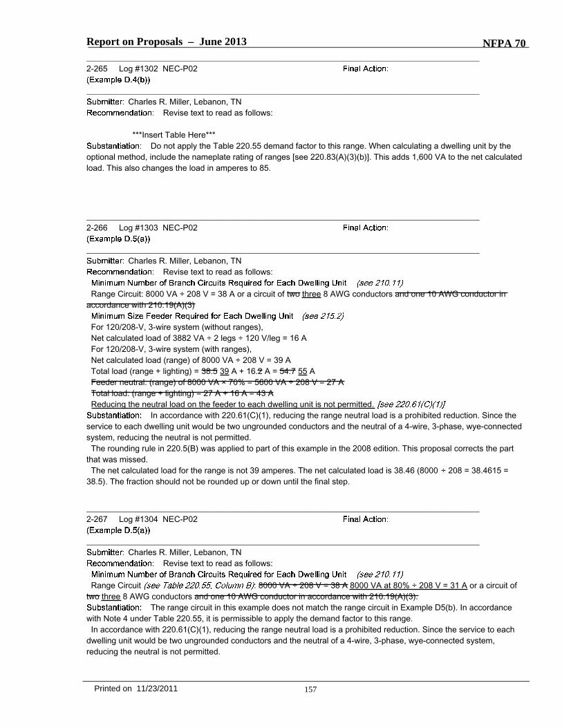
Report on Proposals – June 2013 NFPA 70_______________________________________________________________________________________________2-265 Log #1302 NEC-P02
_______________________________________________________________________________________________Charles R. Miller, Lebanon, TN
Revise text to read as follows:
***Insert Table Here***Do not apply the Table 220.55 demand factor to this range. When calculating a dwelling unit by the
optional method, include the nameplate rating of ranges [see 220.83(A)(3)(b)]. This adds 1,600 VA to the net calculatedload. This also changes the load in amperes to 85.
_______________________________________________________________________________________________2-266 Log #1303 NEC-P02
_______________________________________________________________________________________________Charles R. Miller, Lebanon, TN
Revise text to read as follows:
Range Circuit: 8000 VA ÷ 208 V = 38 A or a circuit of two three 8 AWG conductors and one 10 AWG conductor inaccordance with 210.19(A)(3)
For 120/208-V, 3-wire system (without ranges),Net calculated load of 3882 VA ÷ 2 legs ÷ 120 V/leg = 16 AFor 120/208-V, 3-wire system (with ranges),Net calculated load (range) of 8000 VA ÷ 208 V = 39 ATotal load (range + lighting) = 38.5 39 A + 16.2 A = 54.7 55 AFeeder neutral: (range) of 8000 VA × 70% = 5600 VA ÷ 208 V = 27 ATotal load: (range + lighting) = 27 A + 16 A = 43 AReducing the neutral load on the feeder to each dwelling unit is not permitted.
In accordance with 220.61(C)(1), reducing the range neutral load is a prohibited reduction. Since theservice to each dwelling unit would be two ungrounded conductors and the neutral of a 4-wire, 3-phase, wye-connectedsystem, reducing the neutral is not permitted.The rounding rule in 220.5(B) was applied to part of this example in the 2008 edition. This proposal corrects the part
that was missed.The net calculated load for the range is not 39 amperes. The net calculated load is 38.46 (8000 ÷ 208 = 38.4615 =
38.5). The fraction should not be rounded up or down until the final step.
_______________________________________________________________________________________________2-267 Log #1304 NEC-P02
_______________________________________________________________________________________________Charles R. Miller, Lebanon, TN
Revise text to read as follows:
Range Circuit : 8000 VA ÷ 208 V = 38 A 8000 VA at 80% ÷ 208 V = 31 A or a circuit oftwo three 8 AWG conductors and one 10 AWG conductor in accordance with 210.19(A)(3).
The range circuit in this example does not match the range circuit in Example D5(b). In accordancewith Note 4 under Table 220.55, it is permissible to apply the demand factor to this range.In accordance with 220.61(C)(1), reducing the range neutral load is a prohibited reduction. Since the service to each
dwelling unit would be two ungrounded conductors and the neutral of a 4-wire, 3-phase, wye-connected system,reducing the neutral is not permitted.
157Printed on 11/23/2011

70/L1302/Tb/A2013/ROP
Application of Demand Factor First 3000 VA at 100% 3,000 VA 5520 VA - 3000 VA = 2520 VA at 35% 882 VA Net Calculated Load 3,882 VA (without range and space heating) Range 6,400 VA 8,000 VA Space Heating (see 220.51) 6,000 VA Water Heater 2,500 VA Net Calculated Load (for individual dwelling unit) 18,782 VA 20,382 VA Size of Each Feeder For 120/240-V, 3-wire system, Net calculated load of 18,782 VA 20,382 VA ÷ 240 V = 78 A 85 A

Report on Proposals – June 2013 NFPA 70_______________________________________________________________________________________________2-268 Log #1305 NEC-P02
_______________________________________________________________________________________________Charles R. Miller, Lebanon, TN
Revise text to read as follows:
Range Circuit : 8000 VA at 80% ÷ 208 V = 31 A or a circuit of two three 8 AWGconductors and one 10 AWG conductor in accordance with 210.19(A)(3).
120/208-V, 3-Wire circuitNet calculated load of 18,782 20,382 VA ÷ 208 V = 90 98 ANet calculated load (lighting line to neutral):3882 VA ÷ 2 legs ÷ 120 V per leg = 16 amperesLine to line = 14,900 16,500 VA ÷ 208 V = 72 79 ATotal load = 16.2 16 A + 71.6 79 A = 88 95 A
In accordance with 220.61(C)(1), reducing the neutral load on this feeder is a prohibited reduction.Since the service to each dwelling unit would be two ungrounded conductors and the neutral of a 4-wire, 3-phase,wye-connected system, reducing the neutral is not permitted.The net calculated load is not 18,782 VA. See my proposal for Annex D, Example D4(b).
158Printed on 11/23/2011