Embed Size (px)
Citation preview

Office for Nuclear RegulationAn agency of HSE
National Final Report on European Council “Stress Tests” for UK Nuclear Power Plants
European Council “Stress Tests” for UK nuclear power plants
National Final Report
December 2011

Office for Nuclear RegulationAn agency of HSE
National Final Report on European Council “Stress Tests” for UK Nuclear Power Plants
© Crown copyright 2011
First published December 2011
ONR Report ONR‐ECST‐REP‐11‐002 Revision 0
You may reuse this information (excluding logos) free of charge in any format or medium, under the terms of the Open Government Licence. To view the licence visit www.nationalarchives.gov.uk/doc/open‐government‐licence/, write to the Information Policy Team, The National Archives, Kew, London TW9 4DU, or email [email protected].
Some images and illustrations may not be owned by the Crown so cannot be reproduced without permission of the copyright owner. Enquiries should be sent to [email protected].
Unless otherwise stated, all corporate names, logos, and Registered® and Trademark™ products mentioned in this website belong to one or more of the respective companies or their respective licensors. They may not be used or reproduced in any manner without the prior written agreement of the owner(s).
For published documents, the electronic copy on the ONR website remains the most current publicly available version and copying or printing renders this document uncontrolled.
This document is issued by the Office for Nuclear Regulation (ONR), an agency of HSE. For further information about ONR, or to report inconsistencies or inaccuracies in this publication please visit www.hse.gov.uk/nuclear

Office for Nuclear RegulationAn agency of HSE
National Final Report on European Council “Stress Tests” for UK Nuclear Power Plants Page (i)
Executive Summary Following the events at Fukushima, Japan, on 11 March 2011, the nuclear industry in the UK responded quickly to review UK plants against seismic and flooding hazards. HM Chief Inspector of Nuclear Installations was asked by the Secretary of State for Energy and Climate Change to produce interim and final reports on the lessons to be learnt from these events for the UK nuclear industry. Subsequently, the European Council (EC) requested a review of safety at European nuclear power plants (NPP) and the European Nuclear Safety Regulators Group (ENSREG) produced criteria and a plan for this review, now known as the “stress tests”.
The UK lessons learnt and EC stress tests assessments share common themes and the UK licensees and the Office for Nuclear Regulation (ONR) are using the same or similar teams to ensure the reviews are completed efficiently and effectively. HM Chief Inspector’s interim and final reports were published in May and October 2011 respectively. This report is the national UK stress tests report to the EC presenting the results from the stress tests as applied to UK NPPs. These should be considered in relation to the fundamental philosophy for nuclear safety of continuous improvement, as embedded in UK law for licensed nuclear power plants, of reducing risks so far as is reasonably practicable.
As a result of ONR’s inspections and technical exchange meetings with the licensees along with a review of the licensees’ submissions, ONR confirms in this report that the UK licensees have completed adequate stress tests reviews in line with ENSREG specification. Notwithstanding this, it is also clear to ONR that, to date, the licensees have concentrated on demonstrating compliance with modern standards for “design basis”* events and identifying means to ensure greater robustness for events “beyond design basis” rather than, at this time, undertaking detailed theoretical calculation of margins for which there are likely to be considerable uncertainties. This is a reasonable strategy given the timescales but does not negate the need for licensees to address the ONR findings defined below.
Neither the reviews undertaken by the licensees for the stress tests, nor the earlier national reviews has indicated any fundamental weaknesses in the definition of design basis events or the safety systems related to the stress tests† to withstand them for UK NPPs. However, some aspects of the stress tests will need to be extended with more robust methodologies. In the meantime, ONR expects UK licensees to implement reasonably practicable safety improvements they have already identified to enhance the resilience of emergency response equipment and severe accident procedures in a timely manner.
As noted above, the UK lessons learnt and EC stress tests assessments share common themes and in response to both licensees have derived a significant number of potential improvements, mainly to enhance resilience for emergency actions following events beyond the design basis or not currently foreseen, and also to enhance margin assessment methods. There are also potential improvements to the type or number of barriers to some hazards, e.g. flooding, which should increase defence in depth against events beyond design basis.
The full list of further studies and potential improvements (referred to as “Considerations” by the licensees) to increase defence in depth against events beyond design basis identified by the licensees is extensive and wide‐ranging and is detailed within this report.
Further to the additional studies and potential improvements identified by the licensees ONR’s review of the licensees’ stress tests has resulted in a number of findings as detailed below. Some of these findings reinforce or extend those identified by the licensees while others are additional to those already identified.
* See the glossary at the end of this report † Throughout this report where reference is made to “design basis” or “safety systems”, it relates to the initiating events referred to in the stress tests unless otherwise identified.

Office for Nuclear RegulationAn agency of HSE
National Final Report on European Council “Stress Tests” for UK Nuclear Power Plants Page (ii)
It should also be noted that the findings raised in this report generally relate to more specific aspects of the recommendations already raised by HM Chief Inspector of Nuclear Installations. A table mapping licensees Considerations, the Chief Inspector’s recommendations and ONR’s stress tests findings (STF) is included in the report to show their relationship (see Annex 4).
ONR expects that the stress tests process will finish when the improved processes, plant and procedures move into the licensees’ normal procedures for change and review of safety cases in line with relevant licence conditions. It is anticipated that a further report confirming this transition will be published by ONR in the autumn of 2012. To support this and ensure appropriate progress is being made by the licensees, ONR has raised an STF (number 19), which states that the progress made in addressing the potential improvements identified both by the licensees and by the ONR findings, should be provided to ONR on the same timescale as that for HM Chief Inspector’s recommendations (June 2012). It is expected that these will include the status of plans for delivery of remaining items and details of improvements that have been implemented.
ONR will also seek to take advantage of the EC’s peer reviews not only of this report but the totality of the process to identify further opportunities for continuous improvement.
Note, the findings below relate only to the licensees considered within this report, i.e. those who deal with operating or defuelling NPPs – namely EDF Energy Nuclear Generation Ltd (EDF NGL), Magnox Ltd, Sellafield Ltd, and Dounreay Site Restoration Ltd (DSRL). Defuelled reactors, as former NPPs, are out of the scope of EC stress tests. They are nonetheless considered in a similar process, being conducted in parallel by ONR which covers all other licensed nuclear installations within the UK. The degree to which each finding applies to each NPP is subject to the point in the lifecycle of the plant and will need to be agreed with ONR.
Table 0: ONR’s Stress Tests Findings
Finding No.
ONR’s Stress Tests Findings
STF‐1 Licensees should provide ONR with the decision‐making process to be applied to their Considerations along with a report which describes the sentencing of all their Considerations. The report will need to demonstrate to ONR that the conclusions reached are appropriate.
STF‐2 The nuclear industry should establish a research programme to review the Seismic Hazard Working Party (SHWP) methodology against the latest approaches. This should include a gap analysis comparing the SHWP methodology with more recent approaches such as those developed by the Senior Seismic Hazard Analysis Committee (SSHAC).
STF‐3 Licensees should undertake a further review of the totality of the required actions from operators when they are claimed in mitigation within external hazards safety cases. This should also extend into beyond design basis events as appropriate.
STF‐4 Licensees should undertake a further systematic review of the potential for seismically‐induced fire which may disrupt the availability of safety‐significant structures, systems and components (SSC) in the seismic safety case and access to plant areas.
STF‐5 Licensees should further review the margins for all safety‐significant structures, systems and components (SSC), including cooling ponds, in a structured systematic and comprehensive manner to understand the beyond design basis sequence of failure and any cliff‐edges that apply for all external hazards.
STF‐6 Licensees should review further the margin to failure of the containment boundary and the point at which containment pressure boundary integrity is lost should be clearly established for the advanced gas‐cooled reactors (AGR) and Magnox stations.

Office for Nuclear RegulationAn agency of HSE
National Final Report on European Council “Stress Tests” for UK Nuclear Power Plants Page (iii)
Finding No.
ONR’s Stress Tests Findings
STF‐7 Licensees should undertake a more structured and systematic study of the potential for floodwater entry to buildings containing safety‐significant structures, systems and components (SSC) from extreme rainfall and / or overtopping of sea defences.
STF‐8 Licensees should further investigate the provision of suitable event‐qualified connection points to facilitate the reconnection of supplies to essential equipment for beyond design basis events.
STF‐9 Licensees should further investigate the enhancement of stocks of essential supplies (cooling water, fuel, carbon dioxide, etc.) and extending the autonomy time of support systems (e.g. battery systems) that either provide essential safety functions or support emergency arrangements.
STF‐10 Licensees should identify safety‐significant prime mover‐driven generators and pumps that use shared support systems (including batteries, fuel, water and oil) and should consider modifying those prime movers systems to ensure they are capable of being self‐sufficient.
STF‐11 Licensees should further consider resilience improvements to equipment associated with the connection of the transmission system to the essential electrical systems (EES) for severe events.
STF‐12 Magnox Ltd should assess the progressive loss of electrical systems on all aspects of the fuel route and address any implications.
STF‐13 Magnox Ltd should demonstrate that all reasonably practical means have been taken to ensure integrity of the fuel within the dry fuel stores in the extremely unlikely event of the natural draft air ducting becoming blocked.
STF‐14 Licensees should confirm the extent to which resilience enhancements are to be made to existing equipment and systems that are currently installed at nuclear power plants. Information should be provided on the equipment and systems that may be affected and the nature of the resilience enhancements, including interconnectivity with mobile back‐up equipment.
STF‐15 Licensees should complete the various reviews that they have highlighted so that ONR can assess their proposals and associated timescales. These reviews should look in detail at on‐site emergency facilities and arrangements, off‐site facilities, facilities for remote indication of plant status, communication systems, contents and location of beyond design basis containers and the adequacy of any arrangements necessary to get people and equipment on to and around site under severe accident conditions. Any changes to arrangements and equipment will require appropriate training and exercising.
STF‐16 Licensees should review the symptom‐based emergency response guidelines (SBERG) and severe accident guidelines (SAG) taking into account improvements to the understanding of severe accident progression, phenomena and the equipment available to mitigate severe accident. This review should also take into account the fuel route. Once completed, appropriate training and exercising should be arranged.
STF‐17 Licensees should further review the systems required to support long‐term claims on the pre‐stressed concrete pressure vessel containment capability in severe accident conditions.
STF‐18 EDF Energy Nuclear Generation Ltd should complete its feasibility study into the installation of filtered containment venting, installation of passive autocatalytic hydrogen recombiners and flexible means of injecting water into the Sizewell B containment.
STF‐19 Reports on the progress made in addressing the conclusions of the licensees Considerations and the ONR findings should be made available to ONR on the same timescale as that for HM Chief Inspector’s recommendations (June 2012). These should include the status of plans and details of improvements that have been implemented.

Office for Nuclear RegulationAn agency of HSE
National Final Report on European Council “Stress Tests” for UK Nuclear Power Plants Page (iv)
Contents 0 INTRODUCTION........................................................................................................................................ 1
0.1 Background ...................................................................................................................................... 1 0.1.1 The Fukushima Events...................................................................................................................... 1 0.1.2 UK Response .................................................................................................................................... 2 0.1.3 EC Response ..................................................................................................................................... 2 0.1.4 Other International Responses ........................................................................................................ 3
0.2 ENSREG Requirements ..................................................................................................................... 3 0.2.1 Initiating Events ............................................................................................................................... 3 0.2.2 Loss of Safety Function .................................................................................................................... 4 0.2.3 Severe Accident Management ......................................................................................................... 4
0.3 Relevant Aspects of UK Regulatory Regime..................................................................................... 5 0.3.1 Legal Framework ............................................................................................................................. 5 0.3.2 Licensing .......................................................................................................................................... 5 0.3.3 Design Basis ..................................................................................................................................... 6 0.3.4 Fault Analysis ................................................................................................................................... 6 0.3.5 Severe Accident Management ......................................................................................................... 7 0.3.6 Periodic Safety Review..................................................................................................................... 7 0.3.7 Continuous Improvement ................................................................................................................ 7
0.4 Process for Stress Tests Activities .................................................................................................... 8 0.4.1 Overview and Timeline .................................................................................................................... 8 0.4.2 Licensee Processes for producing Stress Tests Reports.................................................................... 9 0.4.3 ONR’s Assessment Process............................................................................................................. 10 0.4.4 ONR’s Reporting Process................................................................................................................ 11
1 GENERAL DATA ABOUT THE SITES AND NPPS ....................................................................................... 12
1.1 Brief Description of the Site Characteristics .................................................................................. 12 1.1.1 Main Characteristics of UK NPPs ................................................................................................... 13 1.1.2 Description of the Systems for Conduction of Main Safety Functions ........................................... 31
1.2 Significant Differences Between Units........................................................................................... 45 1.3 Use of PSA as Part of the Safety Assessment................................................................................. 45 1.4 ONR’s Conclusion ........................................................................................................................... 49
1.4.1 General Data About the Sites and NPPs ........................................................................................ 49 1.4.2 Main Characteristics of UK NPPs ................................................................................................... 49 1.4.3 Description of the Systems for Conduction of Main Safety Functions ........................................... 49 1.4.4 Significant Differences Between Units ........................................................................................... 50 1.4.5 Use of PSA as Part of the Safety Assessment................................................................................. 50
2 EARTHQUAKES ....................................................................................................................................... 52
2.1 Design Basis.................................................................................................................................... 52 2.1.1 Earthquake Against Which the Plants Are Designed ..................................................................... 52 2.1.2 Provisions to Protect the Plants Against the Design Basis Earthquake.......................................... 55 2.1.3 Compliance of the Plants with Its Current Licensing Basis............................................................. 62

Office for Nuclear RegulationAn agency of HSE
National Final Report on European Council “Stress Tests” for UK Nuclear Power Plants Page (v)
2.2 Evaluation of Safety Margins ......................................................................................................... 65 2.2.1 Range of Earthquake Leading to Severe Fuel Damage.................................................................. 65 2.2.2 Range of Earthquake Leading to Loss of Containment Integrity ................................................... 67 2.2.3 Earthquake Exceeding the Design Basis Earthquake for the Plants and Consequent Flooding
Exceeding Design Basis Flood (DBF)............................................................................................... 69 2.2.4 Measures Which Can Be Envisaged to Increase Robustness of the Plants Against Earthquakes ..69
2.3 ONR’s Conclusion ........................................................................................................................... 70 3 FLOODING.............................................................................................................................................. 72
3.1 Design Basis.................................................................................................................................... 73 3.1.1 Flooding Against Which the Plants Are Designed.......................................................................... 73 3.1.2 Provisions to Protect the Plants Against the Design Basis Flood ................................................... 76 3.1.3 Plants Compliance with its Current Licensing Basis ....................................................................... 78
3.2 Evaluation of Safety Margins ......................................................................................................... 80 3.2.1 Estimation of Safety Margin against Flooding............................................................................... 80 3.2.2 Measures Which Can Be Envisaged to Increase Robustness of the Plants Against Flooding......... 80 3.2.3 ONR’s Assessment of Evaluation of Safety Margins ...................................................................... 81
3.3 ONR’s Conclusion ........................................................................................................................... 82 4 EXTREME WEATHER CONDITIONS......................................................................................................... 89
4.1 Design Basis.................................................................................................................................... 89 4.1.1 Reassessment of Weather Conditions used as Design Basis.......................................................... 89
4.2 Evaluation of Safety Margins ......................................................................................................... 96 4.2.1 Estimation of Safety Margin above Design Basis Events Against Extreme Weather Conditions ... 96 4.2.2 Measures Which Can Be Envisaged to Increase Robustness of the Plants Against Extreme
Weather Conditions ..................................................................................................................... 101 4.3 ONR’s Conclusion ......................................................................................................................... 103
5 LOSS OF ELECTRICAL POWER AND LOSS OF ULTIMATE HEAT SINK..................................................... 104
5.1 Loss of Electrical Power................................................................................................................ 104 5.1.1 Loss of Off‐site Power .................................................................................................................. 104 5.1.2 Loss of Off‐site Power and Loss of the Ordinary Back‐up AC Power Source ................................ 108 5.1.3 Loss of Off‐site Power and Loss of the Ordinary Back‐up AC Power Sources, and Loss of
Permanently Installed Diverse Back‐up AC Power Sources.......................................................... 111 5.1.4 Licensee Conclusion on the Adequacy of Protection Against Loss of Electrical Power ................ 113 5.1.5 Measures Which Can Be Envisaged to Increase Robustness of the Plants in Case of Loss of
Electrical Power ........................................................................................................................... 114 5.1.6 ONR’s Assessment of Loss of Electrical supplies .......................................................................... 115
5.2 Loss of the Decay Heat Removal Capability / Ultimate Heat Sink ............................................... 117 5.2.1 Design Provisions to Prevent the Loss of the Primary Ultimate Heat Sink, such as Alternative Inlets
for Seawater or Systems to Protect Main Water Inlet from Blocking.......................................... 120 5.2.2 Loss of the Primary Ultimate Heat Sink ....................................................................................... 121 5.2.3 Loss of the Primary Ultimate Heat Sink and the Alternate Heat Sink .......................................... 123 5.2.4 Conclusion on the Adequacy of Protection against Loss of Ultimate Heat Sink........................... 124 5.2.5 Measures Which Can Be Envisaged to Increase Robustness of the Plants in Case of Loss of
Ultimate Heat Sink....................................................................................................................... 125

Office for Nuclear RegulationAn agency of HSE
National Final Report on European Council “Stress Tests” for UK Nuclear Power Plants Page (vi)
5.2.6 ONR’s Assessment of Loss of the Decay Heat Removal Capability / Ultimate Heat Sink............. 126 5.3 Loss of the Primary Ultimate Heat Sink, Combined with Station Black‐out ................................ 128
5.3.1 Time of Autonomy of the Site before Loss of Normal Cooling Condition of the Reactor Core and Spent Fuel Pool ............................................................................................................................ 129
5.3.2 External Actions Foreseen to Prevent Fuel Degradation.............................................................. 130 5.3.3 Measures Which Can Be Envisaged to Increase Robustness of the Plants in Case of Loss of
Primary Ultimate Heat Sink, Combined with Station Black‐out................................................... 131 5.3.4 ONR’s Assessment of Loss of Primary Ultimate Heat Sink Combined with Station Blackout....... 131
5.4 ONR’s Conclusion ......................................................................................................................... 132 6 SEVERE ACCIDENT MANAGEMENT...................................................................................................... 133
6.1 Organisation and Arrangements of the Licensee to Manage Accidents...................................... 133 6.1.1 Organisation of the Licensee to Manage the Accident ................................................................ 133 6.1.2 Possibility to Use Existing Equipment .......................................................................................... 138 6.1.3 Evaluation of Factors That May Impede Accident Management and Respective Contingencies 140 6.1.4 Conclusion on the Adequacy of Organisational Issues for Accident Management...................... 143 6.1.5 Measures Which Can Be Envisaged to Enhance Accident Management Capabilities ................. 144 6.1.6 ONR’s Assessment of the Organisation and Arrangements of the Licensee to Manage Accidents
..................................................................................................................................................... 144 6.2 Accident Management Measures in Place at the Various Stages of a Scenario of Loss of the Core
Cooling Function .......................................................................................................................... 146 6.2.1 Before Occurrence of Fuel Damage in the Reactor Pressure Vessel ............................................ 146 6.2.2 After Occurrence of Fuel Damage in the Reactor Pressure Vessel............................................... 147 6.2.3 After Failure of the Reactor Pressure Vessel ................................................................................ 147 6.2.4 ONR’s Assessment of Accident Management Measures in Place at the Various Stages of a
Scenario of Loss of the Core Cooling Function ............................................................................. 148 6.3 Maintaining the Containment Integrity after Occurrence of Significant Fuel Damage (up to Core
Meltdown) in the Reactor Core ................................................................................................... 148 6.3.1 Elimination of Fuel Damage / Meltdown in High Pressure .......................................................... 148 6.3.2 Management of Hydrogen Risks Inside the Containment ........................................................... 149 6.3.3 Prevention of Overpressure of the Containment ......................................................................... 150 6.3.4 Prevention of Re‐Criticality .......................................................................................................... 151 6.3.5 Prevention of Basemat Melt Through.......................................................................................... 152 6.3.6 Need for and Supply of Electrical AC and DC Power and Compressed Air to Equipment used for
Protecting Containment Integrity ................................................................................................ 153 6.3.7 Measuring and Control Instrumentation Needed for Protecting Containment Integrity............. 154 6.3.8 Capability for Severe Accident Management in Case of Simultaneous Core Melt / Fuel Damage
Accidents at Different Units on the Same Site ............................................................................. 154 6.3.9 Conclusion on the Adequacy of Severe Accident Management Systems for Protection of
Containment Integrity.................................................................................................................. 155 6.3.10 Measures Which Can Be Envisaged to Enhance Capability to Maintain Containment Integrity
after Occurrence of Severe Fuel Damage .................................................................................... 155 6.3.11 ONR’s Assessment of Maintaining the Containment Integrity after Occurrence of Significant Fuel
Damage (up to Core Meltdown) in the Reactor Core................................................................... 156 6.4 Accident Management Measures to Restrict the Radioactive Releases ..................................... 158
6.4.1 Radioactive Releases after Loss of Containment Integrity........................................................... 158

Office for Nuclear RegulationAn agency of HSE
National Final Report on European Council “Stress Tests” for UK Nuclear Power Plants Page (vii)
6.4.2 Accident Management after Uncovering of the Top of Fuel in the Fuel Pool .............................. 158 6.4.3 Conclusion on the Adequacy of Measures to Restrict the Radioactive Releases ......................... 164 6.4.4 ONR’s Assessment of Accident Management Measures to Restrict the Radioactive Releases ... 164
6.5 ONR’s Conclusion ......................................................................................................................... 165 7 GENERAL CONCLUSION ....................................................................................................................... 166
7.1 Key Provisions Enhancing Robustness (Already Implemented)................................................... 166 7.2 Safety Issues................................................................................................................................. 166 7.3 Potential Safety Improvements and Further Work Forecasted................................................... 167 7.4 Peer Reviews ................................................................................................................................ 168
ANNEX 1: CHIEF NUCLEAR INSPECTOR’S CONCLUSIONS AND RECOMMENDATIONS................................. 169
ANNEX 2: EDF NGL STRESS TESTS CONSIDERATIONS .................................................................................. 180
ANNEX 3: MAGNOX LTD STRESS TESTS CONSIDERATIONS.......................................................................... 196
ANNEX 4: OVERALL SUMMARY TABLE OF RECOMMENDATIONS OR ACTIONS IN THE UK ......................... 197
8 REFERENCES......................................................................................................................................... 198
9 GLOSSARY AND ABBREVIATIONS......................................................................................................... 200
10 CONTACTS............................................................................................................................................ 205

Office for Nuclear RegulationAn agency of HSE
National Final Report on European Council “Stress Tests” for UK Nuclear Power Plants Page 1 of 205
0
INTRODUCTION 1 This report presents the UK national report to the European Council (EC) on the implementation
of the stress tests to UK nuclear power plants (NPP).
2 The stress tests are defined as a targeted reassessment of the relevant design bases and safety margins of NPPs in the light of the events which occurred at Fukushima: extreme natural events challenging the plant safety functions and leading to a severe accident.
3 All of the UK licensees of operating and defuelling NPPs have undertaken programmes of work to complete all aspects of the stress tests and have provided contributions to the UK national report by the required timescales. In order to fulfil the scope of the stress tests in a meaningful way, the licensees’ reports necessarily include sensitive information regarding the systems necessary to ensure safety of the facility. The Office for Nuclear Regulation (ONR) has had full and unfettered access to all of this information. In order to balance the requirement to protect sensitive information with the requirement to be as open and transparent as possible, links to published versions of all licensee contributions will be available on the ONR web pages.
4 In the UK, the licensees responded rapidly to initial requests for reviews of design basis and beyond design basis events by ONR and by the World Association of Nuclear Operators (WANO) shortly after the start of the sequence of events at Fukushima. They have also supported and provided information for HM Chief Inspector’s reports on the implications of the Japanese earthquake and tsunami for the UK nuclear industry. These activities and the work for the EC stress tests have strong synergies and overlaps. UK licensees have taken account of these where possible, and have worked together to provide a consistent UK nuclear industry response where appropriate.
0.1 Background 5 All of the UK nuclear site licensees have processes to assimilate, review and disseminate lessons
learnt from significant events, both in the UK and overseas. These arrangements are part of the continuous improvement and operational experience (OPEX) feedback processes which are required to all licensees through Licence Conditions (LC).
6 The magnitude and scale of the events at Fukushima are such that all the NPP operators responded swiftly and proactively to review safety at their sites. In addition, they have been fully supportive and engaged in the wider UK nuclear industry responses and international lessons to learn from these events.
0.1.1 The Fukushima Events
7 On 11 March 2011 Japan suffered its worst recorded earthquake, known as the Tohuku event. The epicentre was 110 miles east north east from the Fukushima Dai‐ichi (Fukushima‐1) site. Reactor Units 1, 2 and 3 on this site were operating at power before the event and on detection of the earthquake, shut down safely. Off‐site power was lost and initially emergency diesel generator (EDG) power was used to provide essential post‐trip cooling. Less than an hour after shutdown a massive tsunami from the earthquake inundated the site and destroyed the capability for on‐site generation of alternating current (AC) electrical power. Sometime later, alternative back‐up cooling was lost. With the loss of cooling systems, Reactor Units 1 to 3 overheated. The overheated zirconium cladding reacted with water and steam, generating

Office for Nuclear RegulationAn agency of HSE
National Final Report on European Council “Stress Tests” for UK Nuclear Power Plants Page 2 of 205
hydrogen which resulted in several explosions causing damage to building structures. Major releases of radioactivity occurred, initially to the atmosphere but later by leakage to sea. The operator struggled to restore full control.
8 This was a major nuclear accident, rated at an International Nuclear and Radiological Event Scale (INES) level 7 (the highest level). The Japanese authorities instigated a 20km evacuation zone, a 30km sheltering zone and other countermeasures.
0.1.2 UK Response
9 In response to the Fukushima accident, the UK opened the Cabinet Office Briefing Room (COBR). The Government Chief Scientific Advisor chaired a Scientific Advisory Group for Emergencies (SAGE). HM Chief Inspector of Nuclear Installations provided significant inputs to both COBR and SAGE. The Redgrave Court Incident Suite in Bootle was staffed by ONR from early in the accident and for over two weeks; it acted as a source of expert regulatory analysis, advice and briefing to central government departments and SAGE.
10 The Secretary of State for Energy and Climate Change requested HM Chief Inspector of Nuclear Installations to examine the circumstances of the Fukushima accident to see what lessons could be learnt for the UK nuclear industry. ONR set up a dedicated project team covering aspects of the Fukushima accident that are likely to be important for learning lessons. HM Chief Inspector of Nuclear Installations set up a Technical Advisory Panel (TAP) of external independent experts to advise him during this work.
11 HM Chief Inspector of Nuclear Installations published his interim report on the events at Fukushima and the implications for the UK nuclear industry on 18 May 2011 (Ref. 1). This report contained 11 conclusions and 26 recommendations. Many of the recommendations covered topics similar to those in the stress tests and UK licensees were reminded of the potential synergies in the work for the recommendations and for the stress tests in the letters which requested them to undertake stress tests.
12 HM Chief Inspector of Nuclear Installations published his final report on 11 October 2011 (Ref. 2). This report built on the findings of the interim report and added a further six conclusions and 12 recommendations. All of the conclusions and recommendations from both these two reports are listed at Annex 1.
0.1.3 EC Response
13 On 24 and 25 March 2011, the European Council declared that “the safety of all EU nuclear plants should be reviewed, on the basis of a comprehensive and transparent risk assessment (“stress tests”). European Nuclear Safety Regulators Group (ENSREG) and the European Commission are invited to develop, as soon as possible, the scope and modalities of these tests in a coordinated framework, in light of the lessons learnt from the accident in Japan and with the full involvement of member states, making full use of available expertise (notably from the Western European Nuclear Regulators’ Association (WENRA). The assessments will be conducted by independent national authorities and through peer review; their outcome and any necessary subsequent measures that will be taken should be shared with the Commission and within ENSREG and should be made public. The EC will assess initial findings by the end of 2011, on the basis of a report from the Commission”. The European Commission is to present its final report to the EC in June 2012.

Office for Nuclear RegulationAn agency of HSE
National Final Report on European Council “Stress Tests” for UK Nuclear Power Plants Page 3 of 205
14 ENSREG members agreed on the initial independent regulatory technical definition of the stress tests and how it should be applied to nuclear facilities across Europe at their plenary meeting on the 12–13 May 2011.
0.1.4 Other International Responses
15 HM Chief Inspector of Nuclear Installations led an International Atomic Energy Agency (IAEA) high‐level team of international nuclear experts in a fact‐finding mission to Japan in May 2011. HM Chief Inspector of Nuclear Installations reported back to a ministerial conference of the IAEA in June 2011 and the mission team produced a report (Ref. 3). A crucial initial finding of the mission team was that the tsunami risk for several sites in Japan had been underestimated. It also concluded that regulatory systems should ensure that there are adequate arrangements for addressing extreme events, including periodic review of those arrangements. The EC stress tests are part of this process. The IAEA has developed an action plan, which was endorsed by the IAEA at its General Conference in September 2011.
16 The Japanese government has provided two reports on the accident to the IAEA: to the Ministerial Conference, published in June 2011 (Ref. 4), and to the General Conference, published in September 2011 (Ref. 5).
17 An extraordinary Review Meeting of the Convention on Nuclear Safety to review contracting parties’ progress against the Action Plan will be held in August 2012.
18 The UK has contributed to a significant number of other international meetings and bilateral discussions relating to the Fukushima accident since March 2011, and this is expected to continue. ONR’s staff, led by HM Chief Inspector of Nuclear Installations, play an active role in these meetings.
0.2 ENSREG Requirements 19 The ENSREG requirements (Ref. 6) are included in Annex 1 of the ONR National Progress Report
(Ref. 7).
20 ENSREG notes that licensees have the prime responsibility for safety, so they should perform the assessments and the regulatory body should independently review them.
21 The national regulatory bodies have been encouraged to take due account of the principles for openness and transparency and to make their reports available to the public within the bounds of security and international obligations. This accords well with ONR’s existing openness and transparency objectives. ENSREG also notes that the reports from the peer review process will be made public.
0.2.1 Initiating Events
22 The initiating events required for review under the stress tests are earthquakes, flooding and bad weather. In each case the review considers the size and frequency of the design basis event and how it was developed, along with a review of how structures, systems and components (SSC) were designed or qualified to resist the design basis event(s).
23 In the UK, the licensees reviewed compliance with their safety cases in the first few days after the Fukushima event following separate requests from ONR and WANO. ONR monitored the work

Office for Nuclear RegulationAn agency of HSE
National Final Report on European Council “Stress Tests” for UK Nuclear Power Plants Page 4 of 205
undertaken by the licensees. The findings were generally positive, although some minor issues were identified; these were quickly resolved by the licensees.
24 The initiating event review for the stress tests must also consider how the safety margins evaluation for each NPP or SSC was completed and what consequential effects should be considered. The evaluation of safety margins includes a requirement for licensees to consider what improvements, if any, could be applied to improve margins and to remove or reduce further the probability of cliff‐edge effects. Complementary work is already underway on these matters in the UK as a result of recommendations in HM Chief Inspector’s report on Fukushima (Ref. 2) (see Annex 4).
0.2.2 Loss of Safety Function
25 Two key, loss of safety function fault sequences must be reviewed during the stress tests, both separately and in combination. These are:
Loss of electrical power.
Loss of ultimate heat sink.
26 These events which could lead to a loss of nuclear safety function, such as cooling, could be as a result of seismic activity or flooding, but other external or internal hazards, or faults could also be the initiator of these sequences. This is recognised in the text of the ENSREG requirements and has been considered by the licensees. This means that the impact of any findings will have a broader application than just seismic activity, flooding or extreme weather.
27 For loss of electrical power, progressive loss of supplies is considered. This starts with a loss of off‐site power (LOOP) – this is always considered as a fault scenario in UK design basis and resilience is provided by a range of on‐site power generation and support facilities. The more severe sequence also considered for the stress tests is the loss of all off‐ and on‐site AC power generation capacity; this is generally known as station blackout (SBO). In common with the initiating events, an evaluation of safety margins is requested along with a review of what improvements, if any, could be applied to improve margins and to remove or reduce further the probability of cliff‐edge effects.
28 For loss of ultimate heat sink, initially the normal cooling systems are considered unavailable, and then progressive loss of alternative and back‐up cooling systems (BUCS) is reviewed.
29 For the final sequence, a loss of ultimate heat sink along with SBO is considered. This is an extreme fault condition and the stress tests then look for information on how the fault would escalate into a severe accident and the timescales involved. A review of potential margins and of improvements, if any, which could be applied to improve margins and to remove or reduce further the probability of cliff‐edge effects, is required.
30 It is worth noting that complementary work on electrical supplies and cooling supplies is already underway in the UK as a result of Recommendations IR‐17, IR‐18, IR‐19 and IR‐20 in HM Chief Inspector’s report on Fukushima (Ref. 2) (see Annex 4).
0.2.3 Severe Accident Management
31 The ENSREG requirements for severe accident management recognise that most severe accident management arrangements are there to mitigate the worst effects, not to prevent them occurring.

Office for Nuclear RegulationAn agency of HSE
National Final Report on European Council “Stress Tests” for UK Nuclear Power Plants Page 5 of 205
32 The review asks for the key management features to ensure control, cooling and containment along with instrumentation to confirm key parameters, and for the potential accident management measures which could be applied by the licensees to be considered in a systematic manner.
33 The review also builds on learning from Fukushima about damage to the local and regional infrastructure and communications and the potential for a long duration of standalone activity at the site in the face of major regional disruption. As before, potential cliff‐edges are to be identified, along with any potential improvements that could improve margins and remove or reduce the probability of cliff‐edge effects.
34 Recommendations IR‐24 and IR‐25 of HM Chief Inspector’s report (Ref. 2) are relevant here.
0.3 Relevant Aspects of UK Regulatory Regime
0.3.1 Legal Framework
35 In the UK, the legal framework for nuclear safety is established principally through the:
Health and Safety at Work etc. Act 1974 (HSWA74).
Nuclear Installations Act 1965 (NIA65) (as amended).
36 Under HSWA74 employers are responsible for reducing risks, so far as is reasonably practicable, to their workers and the public. This responsibility is elaborated further in relation to nuclear sites by NIA65, which establishes a nuclear site licensing regime. The power to grant a licence to use a site to construct and operate a specified nuclear installation, and its subsequent regulation, is vested in the Health and Safety Executive (HSE), which further delegates this authority to HM Chief Inspector of Nuclear Installations. This power includes attaching conditions in the interests of safety or radioactive waste management.
37 European legislation in the form of EC Directives is transposed into the UK legal framework outlined above. The most recent European legislation is the Nuclear Safety Directive, which came into force in July 2011.
38 ONR is an agency of HSE, and is the principal regulator of the safety and security of the nuclear industry in the UK; its independence is secured legally through HSWA74. ONR is mainly formed from three former bodies: the HSE Nuclear Directorate, UK Safeguards Office and Office for Civil Nuclear Security. In addition, ONR recently took on the nuclear regulatory functions of the Department for Transport, by incorporation of the Radioactive Materials Transport Team.
0.3.2 Licensing
39 Regulation of the safety of nuclear installations in the UK is through a system of control based on a licensing regime within which a corporate body is granted a licence to use a site for specific activities. This allows ONR to regulate the design, construction, operation and decommissioning of any nuclear installation for which a nuclear site licence is required under NIA65. Nuclear site licences are granted for an indefinite term and a single licence may cover the lifetime of an installation.
40 NIA65 allows HM Chief Inspector of Nuclear Installations to attach to each nuclear site licence such conditions as it considers necessary or desirable in the interests of safety, or with respect to the handling, treatment or disposal of nuclear materials. ONR has developed a standard set of 36

Office for Nuclear RegulationAn agency of HSE
National Final Report on European Council “Stress Tests” for UK Nuclear Power Plants Page 6 of 205
LCs, which are (with minor variations) attached to all nuclear site licences. In the main, they require the licensee to make and implement adequate arrangements to address the particular safety areas identified. The LCs provide the prime legal means for ONR’s day‐to‐day regulation of safety at licensed sites. They do not relieve the licensee of the responsibility for safety. They are mostly, but not exclusively non‐prescriptive, setting goals that the licensee is responsible for achieving.
41 One of the requirements of the LCs is that the licensees produce an adequate safety case to demonstrate that facilities are safe in both normal operation and fault conditions. The safety case is a fundamental part of the licensing regime at all stages in the lifecycle of a nuclear installation. It establishes whether a licensee has demonstrated that it understands the hazards associated with its activities and has arrangements to control them adequately.
0.3.3 Design Basis
42 ONR has developed and published its own technical assessment principles, which it uses to judge licensees’ safety cases; these are set out in the Safety Assessment Principles for Nuclear Facilities (SAP) (Ref. 8). The latest version of the SAPs, published in 2006, was benchmarked against extant IAEA safety standards. In addition to the SAPs, more detailed Technical Assessment Guides (TAG, accessible at www.hse.gov.uk/nuclear/tagsrevision.htm) are available to ONR assessors to assist them in making judgements on licensees’ safety submissions. The TAGs also incorporate the WENRA reference levels. In the areas relevant to the accident at the Fukushima site, the SAPs and TAGs set out regulatory expectations for protection against hazards such as extreme weather, flooding, earthquakes, fire, explosion etc., and for the provision of essential services.
43 Specific SAPs and sections of the SAPs define ONR’s expectations for the development of a design basis.
44 Design basis analysis (DBA) provides a robust demonstration of the fault tolerance of a facility and of the effectiveness of its safety measures. Its principal aims are to guide the engineering requirements of the design and to determine limits to safe operation. In this approach, risk is not quantified but the adequacy of the design and the suitability of the safety measures are assessed against deterministic targets.
0.3.4 Fault Analysis
45 Conservative design, defence in depth, good operational practice and adequate maintenance and testing should minimise the likelihood of faults. The DBA should ensure that the facility has been designed to cope with or withstand a wide range of faults without unacceptable consequences by virtue of the plant’s inherent characteristics or its safety features.
46 In addition to DBA, Probabilistic Safety Analysis (PSA) is also generally used to confirm the overall risk presented by the NPP lies within targets set by the licensees themselves and by ONR in the SAPs (Ref. 8). PSA can also help understand the strengths and weaknesses of the design, particularly in light of the complex designs and interdependencies.
47 DBA may also not include the full range of identified faults because it may not be reasonably practicable to make design provisions against extremely unlikely faults. It may not therefore address severe but very unlikely faults against which the design provisions may be ineffective. This is addressed by severe accident analysis.

Office for Nuclear RegulationAn agency of HSE
National Final Report on European Council “Stress Tests” for UK Nuclear Power Plants Page 7 of 205
0.3.5 Severe Accident Management
48 The principle of defence in depth requires that fault sequences leading to severe accidents are analysed and provision made to address their consequences. The analysis of severe accident events should be performed on a best‐estimate basis to give realistic guidance on the actions which need to be taken in the unlikely event of such an accident occurring. Severe accident analysis may also identify that providing further plant and equipment for accident management is reasonably practicable.
49 All of the UK NPPs had DBA, PSA and severe accident analysis undertaken during their design or in a subsequent periodic safety review (PSR). The stress tests process effectively undertakes a targeted review of specific hazards, loss of key systems and severe accident studies in a systematic manner.
0.3.6 Periodic Safety Review
50 In the UK the operator of a nuclear installation is required by a specific Licence Condition (LC 15) to periodically review its safety case for the plant. This PSR usually takes place every ten years and requires the operator to demonstrate that the original design safety intent is still being met. The reassessment is performed against the latest safety standards and technical knowledge. The operating experience of the plant is also considered in the review. If the PSR identifies any reasonably practicable safety improvements, then it is a legal requirement that these should be made by the licensee. In addition, any life‐limiting factors that would preclude operation for a further ten years should also be identified in the review. The PSR includes a review of the safety of the plant in response to events such as earthquakes, floods, fire and explosion. ONR independently assesses licensees’ PSR reports using its SAPs and TAGs.
51 All of the UK NPPs were designed and built to standards in use at the time. For all of the UK fleet of reactors this involved flooding studies, but for most this did not include seismic design. The initial round of PSR identified the absence of a seismic safety case and a re‐evaluation process was completed to confirm the adequacy of the relevant SSCs and to make necessary modifications to improve seismic resistance.
52 The PSRs for each site take account of modern standards and recent research findings. Over the last two decades, a number of tsunami studies have been completed by the UK nuclear industry or have been commissioned by Government. The outputs from these studies have been considered in the subsequent PSRs.
0.3.7 Continuous Improvement
53 This philosophy is at the core of the UK requirements for the nuclear industry through the application of the as low as reasonably practicable (ALARP) legal requirement, and is the way in which sustained high standards of nuclear safety are realised. It means that, no matter how high the standards of nuclear design and subsequent operation are, the quest for improvement must never stop. Seeking to learn from events, and from new knowledge and experience, is a fundamental feature of the safety culture of the UK nuclear industry.
54 All UK nuclear site licensees have processes to assimilate, review and disseminate lessons learnt from significant events both in the UK and overseas. These arrangements are part of the continuous improvement and OPEX feedback processes which are expected of all licensees.

Office for Nuclear RegulationAn agency of HSE
National Final Report on European Council “Stress Tests” for UK Nuclear Power Plants Page 8 of 205
55 Licensees also participate in the continuous improvement programmes arising from their membership of WANO. The participation of UK licensees in the work of WANO is not a regulatory requirement, but ONR encourages this and the licensees benefit from participation in this international programme which gives them access to a wide pool of shared experiences and peer‐to‐peer reviews.
56 In normal circumstances, feedback from WANO peer reviews and evaluations required by WANO is not made available to ONR or other national regulators and such feedback is not requested. In light of the extraordinary circumstances of the Fukushima event, the output from the WANO‐sponsored evaluations from the major NPP licensees was voluntarily made available to ONR. Two mandatory evaluations were undertaken by the licensees to review the scope and implementation of the external hazards safety cases within the design basis and to review beyond design basis hazards. The work undertaken in these evaluations provided confidence to the licensees and to ONR that the existing safety cases were secure at a time of high concern, and also provided information in support of the subsequent stress tests process.
0.4 Process for Stress Tests Activities
0.4.1 Overview and Timeline
57 The assessment process was required to commence by 1 June 2011 and the major UK NPP licensees, and the potential licensees were informed of this by letter in advance.
58 The major UK licensees were asked to respond by 10 June 2011 confirming that they were aware of, and would act on, the stress tests programme of work and would provide a lead contact to engage with the team in ONR. This was completed in a timely manner.
59 The next major step was for the NPP licensees to submit their stress tests progress reports by 15 August 2011 – this was also completed in a timely manner. ONR has reviewed the information supplied and produced the UK National Progress Report (Ref. 7) by 15 September 2011.
60 The licensees continued work on their main stress tests reports, one for each site, to the prescribed format and submitted them to ONR by the required date of 31 October 2011 (Refs 9 to 23).
61 ONR assessed this information, and submitted the UK National Final Report to the European Commission – this report – by 31 December 2011.
62 In order to enhance credibility and accountability of the process, the EC asked that the national reports should be subject to a peer review process. The peer reviews will be undertaken by teams, including relevant specialists, which will have access to all supporting information, subject to security clearances. The peer reviews will start once the national reports become available and will be completed by the end of April 2012. At the time of writing, the exact composition, extent and reporting of the peer reviews is being developed, and pilots were held in December 2011 which included ONR inspectors.
63 To help the Fukushima response activities move from a unique reactive process back into normal regulatory business, which can be regulated within the existing tried and tested arrangements, the licensees have been asked to produce further reports in the summer of 2012 – responding to HM Chief Inspector’s final report recommendations – to provide an update to their stress tests reports and to produce a consistent, combined overall work programme. ONR then intends to produce a further report about a year after HM Chief Inspector’s final report to provide an update on progress in implementing the lessons for the UK’s nuclear industry.

Office for Nuclear RegulationAn agency of HSE
National Final Report on European Council “Stress Tests” for UK Nuclear Power Plants Page 9 of 205
0.4.2 Licensee Processes for producing Stress Tests Reports
64 In the UK, in line with the goal‐setting non‐prescriptive approach to regulation, the licensees were expected to prepare the information and the initial assessments for each NPP site. The output has been assessed by ONR to confirm it is appropriate and that the licensees have adequately considered the safety margins and how they might be extended.
65 The approach adopted by the licensees was to apply the arrangements made under LC 15 (Periodic Review) to carry out a review and reassessment of safety and submit a report to ONR. This provided a structured framework for the review activities and gave clarity of roles and functions within the licensees’ arrangements for the preparation, review and reassessment of safety case information.
66 The licensees have used their independent oversight and challenge groups to carry out inspection and assessment of the work performed under the stress tests. They have reported this work and its findings to their Nuclear Safety Committees (NSC) and set up other oversight arrangements to ensure the work is comprehensive, accurate and evidence based, as well as timely.
67 The key outputs from the stress tests process beyond the reports themselves are the areas of potential improvement. Where potential improvements to processes or equipment have been identified by the licensees, they have reported them as “Considerations”. These Considerations do not represent commitments to make specific improvements. Rather they will be taken forward by the licensees for examination by a decision making process to determine which of the potential improvements are ALARP, and which should therefore be implemented. Licensees may still choose to implement improvements which are not ALARP, perhaps for commercial or public relations reasons. The EDF Energy Nuclear Generation Ltd (EDF NGL) Considerations are listed in Annex 2 and those for Magnox Ltd are listed in Annex 3. The decision making process and how it is applied and the timescales for implementation of those improvements which are adopted are clearly an areas of interest to ONR. Licensees will be required to justify any decision not to adopt a particular measure, in line with ONR’s normal regulatory process.
68 For EDF NGL’s reactors, the pressurised water reactor (PWR) at Sizewell B has been operating for 16 years, with the advanced gas‐cooled reactors (AGR) operating for between 23 and to 35 years. All of the NPPs have been subject to a plant lifetime extension review by the licensee with the exception of Sizewell B, Torness and Heysham 2. Current plans indicate that the stations will continue operation through a range of dates from 2023 to 2045, subject to periodic reviews of their safety cases and the consent of ONR, as appropriate.
69 With a large operating fleet and long predicted lifetimes, the scope and extent of potential improvements in light of the Considerations from the stress tests and the recommendations from HM Chief Inspector of Nuclear Installations’ reports are significant for EDF NGL. EDF NGL is engaged with the wider EDF group to ensure reviews and options for improvement are consistent (where appropriate) in both France and the UK and to share information and maximise the potential for learning.
70 The operating Magnox reactors may get defuelled in around six years. The short remaining periods for both operation and subsequent defuelling act as a practical constraint on the overall safety benefit that could arise from potential improvements resulting from the stress tests reviews and recommendations in HM Chief Inspector’s report. Magnox Ltd has recognised this and has initiated reviews and optioneering studies to determine if enhancements can be

Office for Nuclear RegulationAn agency of HSE
National Final Report on European Council “Stress Tests” for UK Nuclear Power Plants Page 10 of 205
implemented in a timely manner in order that a real safety benefit is realised. ONR will, of course, scrutinise this review.
71 For the defuelling Magnox reactors, the short remaining periods for defuelling, together with a vastly reduced potential for harm, act as a constraint on potential improvements resulting from the stress tests reviews. Magnox Ltd has recognised this and has initiated reviews and optioneering studies to determine if enhancements can be implemented as soon as practicable in order that a real safety benefit is realised. As above ONR will assess these reviews.
72 The constraints on improvements are similar at the defuelling Calder Hall reactors operated by Sellafield Ltd. Enhancements to site‐wide emergency arrangements identified for the wider Sellafield site are likely to be of benefit to safety at Calder Hall. However, any such Considerations are beyond the scope of this report. The reduction in decay heat and the extent of defuelling are even more pronounced at reactors on the Dounreay site, and therefore Dounreay Site Restoration Ltd’s (DSRL) response reflects this.
73 In ONR’s engagement with the licensees over how the Considerations are taken forward, ONR will take due account of the remaining operating or defuelling lives and how these are factored into the decision‐making process.
0.4.3 ONR’s Assessment Process
74 ONR applies a targeted sampling process to almost all of its activities. In the case of the stress tests reports submitted by the licensees, a team of specialist inspectors has assessed specific sections of reports and looked at how they have been applied generically across the sites. ONR’s detailed assessment has covered all of the key discipline areas of external hazards: seismic, flooding and weather as well as electrical and system fault studies and severe accident and emergency response topic areas.
75 During the licensees’ development of the stress tests reports, ONR’s team of specialists interacted with the licensees in a variety of technical meetings covering the specialist areas and also inspected the processes applied by the licensees to undertake the reviews and develop their potential areas for improvement (the Considerations). Additionally ONR has undertaken specific inspections at a number of licensed sites to revisit the current safety case requirements and how they are implemented, as well as how the stress tests process was applied. When ONR or the licensees identified topics or subjects which could be addressed by a variety of approaches, or where there was the potential for inconsistency in approaches, ONR has held workshops either with a single licensee, or more often with all the major licensees and subsequently, engaged all the licensees through the auspices of the Safety Directors’ Forum.
76 By using a variety of approaches to inspection and assessment, ONR has developed a broad understanding of how the stress tests were applied as well as how they are reported by the licensees. ONR has confirmed that the licensees have met the ENSREG requirements for the stress tests and its reporting, but taking a wider view of how the stress tests have been applied has given ONR a much greater understanding of the strengths and weaknesses reported by the licensees.
77 Part of the ONR assessment process following receipt of the licensees’ full reports, included a formal query tracking system. ONR has also challenged and tested the licensees’ claims and assumptions within technical meetings.

Office for Nuclear RegulationAn agency of HSE
National Final Report on European Council “Stress Tests” for UK Nuclear Power Plants Page 11 of 205
78 At the end of ONR’s assessment, there are a number of queries which remain open, mainly (but not solely) due to the limited time which ONR has had to review the submissions and the time the licensees have had to respond. ONR has also raised a number of topics which require further work by the licensees; these are identified as findings in this report and will be taken forward to resolution. As indicated in the section above, ONR has a strong interest in the decision making process applied by the licensees to their Considerations, and the first stress tests finding is to ensure ONR retains a clear view of the process and its outputs.
STF‐1: Licensees should provide ONR with the decision‐making process to be applied to their Considerations along with a report which describes the sentencing of all their Considerations. The report will need to demonstrate to ONR that the conclusions reached are appropriate.
79 ONR’s findings are summarised in the executive summary. These are generally high level and ONR will therefore provide the licensees with more detailed information on how its expectations may be addressed.
80 It should be noted that the findings described in this stress tests report are supplementary to the recommendations raised in HM Chief Inspector’s reports in that they generally relate to specific aspects of those recommendations. They do not supersede any existing issues or necessary improvements identified by ONR via the normal regulatory engagement processes.
0.4.4 ONR’s Reporting Process
81 ONR has followed the structure and contents of the stress tests report as defined by ENSREG.
82 The structure generally has a description of the information provided by the licensees followed by ONR’s view of that information. This should allow the reader to be clear when a point or comment is the information supplied by the licensees or when it is the view of the Regulator.
83 A draft of ONR’s report was critically reviewed by the TAP set up, to provide HM Chief Inspector of Nuclear Installations with independent advice following the Fukushima events. Where appropriate the advice of the TAP has been incorporated into this report.

Office for Nuclear RegulationAn agency of HSE
National Final Report on European Council “Stress Tests” for UK Nuclear Power Plants Page 12 of 205
1 GENERAL DATA ABOUT THE SITES AND NPPS 1.1 Brief Description of the Site Characteristics 84 This report covers those licensed sites in the UK that contain operational NPPs or
decommissioning NPPs that are in the process of defuelling (referred to as defuelling sites). These are operated by licensees that have completed the stress tests for each site based on the criteria provided in the specification (Ref. 6) developed by ENSREG.
85 There are other licensed sites in the UK where the decommissioning of NPPs has reached a stage where irradiated fuel has been removed from the reactor(s) and fuel storage pond(s) for off‐site reprocessing or storage. These sites are not considered within this report other than where they are located adjacent to an operational or decommissioning NPP that contains irradiated fuel.
86 In NPPs, the heat from nuclear fission is used to produce steam to drive turbines that in turn generate electricity. Different types of reactor generate the steam in different ways. For example, in a boiling water reactor (BWR), such as those involved in the events at Fukushima, the steam is generated directly from the water used to cool the fuel elements in the reactor. In a PWR, the fuel is cooled by water in the primary circuit that then generates steam in a secondary circuit via steam generators; it is the steam from this secondary system that drives the turbines. The UK nuclear industry does not have a BWR and only one PWR within a NPP at Sizewell B in Suffolk.
87 The UK predominantly uses gas‐cooled reactors that employ CO2 gas to take away heat from the fuel elements in the reactor core. The CO2 gas then heats water in boilers to generate steam for the turbines. There are two types of gas‐cooled reactor operating in the UK, namely Magnox reactors and AGRs.
88 Additionally, there are two fast breeder reactors at Dounreay, the Dounreay fast reactor (DFR) and the prototype fast reactor (PFR), which are currently subject to decommissioning activities. These both used liquid metal to remove heat from their respective cores during operation. Both of these reactors are now essentially empty of fuel. However, they are considered in this report as the DFR reactor currently has some breeder elements and one stuck fuel assembly to be removed, and the empty PFR reactor currently has spent fuel and breeder elements stored in its associated storage facilities.
89 The operational NPPs are operated by EDF NGL (the licensee) at Dungeness B in Kent, Hartlepool in Teesside, Heysham in Lancashire, Hinkley Point B in Somerset, Hunterston B in Ayrshire, Sizewell B in Suffolk and Torness in Lothian, and by Magnox Ltd (the licensee) at Oldbury in South Gloucestershire and Wylfa in Anglesey.
90 These operational NPPs are all twin reactor units with the exception of the PWR at Sizewell B, which is a single reactor site. The NPP at Oldbury has one operational Magnox reactor while its other Magnox reactor is shut down awaiting decommissioning.
91 The defuelling sites are operated by Magnox Ltd (the licensee) at Chapelcross in Dumfries and Galloway, Dungeness A in Kent, and Sizewell A in Suffolk. The defuelling site at Calder Hall in Cumbria is operated by Sellafield Ltd (the licensee) and the licensee at Dounreay is DSRL.
92 These defuelling sites have either four or two reactor units, which are permanently shut down. Exceptions to this are the NPP at Oldbury, as outlined above, and the site at Dounreay which has two shut‐down single fast breeder reactors, namely DFR and PFR.

Office for Nuclear RegulationAn agency of HSE
National Final Report on European Council “Stress Tests” for UK Nuclear Power Plants Page 13 of 205
93 The operational NPPs and defuelling sites are:
situated in coastal locations, with the exception of Oldbury which is next to the River Severn, and Chapelcross which is 5km (approx.) north of the Solway Firth; and
located away from major centres of civil population, with electricity generated at the NPPs is transmitted via overhead lines operated by National Grid Electrical Transmission Ltd prior to distribution for industrial, commercial and domestic use. The location of the sites has generally been dictated by planning considerations and the close proximity of a water source to provide an ultimate heat sink. The distance from centres of civil population varies between NPPs.
94 There are currently ten operational NPPs and five defuelling sites in the UK. The geographical location of these sites is shown in Figure 1, below.
Figure 1: Map of UK Showing the Location of NPP Sites
1.1.1 Main Characteristics of UK NPPs
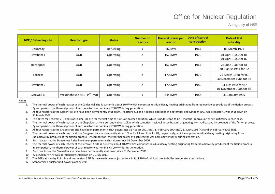
95 The main characteristics of operational NPPs and defuelling sites in the UK are shown in Table 1.

Office for Nuclear RegulationAn agency of HSE
National Final Report on European Council “Stress Tests” for UK Nuclear Power Plants Page 14 of 205
Table 1: Main Characteristics of UK Nuclear Power Stations and Defuelling Sites
NPP / Defuelling site Reactor type Status Number of reactors
Thermal power per reactor
Date of start of construction
Date of first criticality
Calder Hall Magnox
Defuelling 4 260MW1 1953 22 May 1956 for Reactor 1 (R1)2
01 February 1957 for R22,3
16 June 1958 for R32,3
02 April 1959 for R42,3
Chapelcross Magnox
Defuelling 4 260MW4 1955 09 November 1958 for R15
30 May 1959 for R25
31 August 1959 for R35
22 December 1959 for R45
Dounreay DFR Defuelling 1 60MW 1955 14 November 1959
Dungeness A Magnox
Defuelling 2 840MW6 1960 30 August 1965 for R17
06 December 1965 for R27
Sizewell A Magnox
Defuelling 2 840MW8 1960 20 January 1966 for R19 26 May 1966 for R29
Oldbury Magnox Operating (R1) Defuelling (R2)
2 820MW 1961 16 August 1967 for R1 19 November 1967 for R210
Wylfa Magnox Operating 2 1600MW 1963 16 January 1971 for R1 29 June 1971 for R2
Dungeness B AGR Operating 2 1550MW 1965 04 December 1982 for R21
23 December 1985 for R22
Hinkley Point B AGR Operating 2 1320MW11 1967 01 February 1976 for R4 24 September 1976 for R3
Hunterston B AGR Operating 2 1320MW11 1967 31 January 1976 for R3 27 March 1977 for R4
Office for Nuclear RegulationAn agency of HSE
National Final Report on European Council “Stress Tests” for UK Nuclear Power Plants Page 15 of 205
NPP / Defuelling site Reactor type Status Number of reactors
Thermal power per reactor
Date of start of construction
Date of first criticality
Dounreay PFR Defuelling 1 660MW 1967 03 March 1974
Heysham 1 AGR Operating 2 1575MW 1970 01 April 1983 for R1 01 April 1983 for R2
Hartlepool AGR Operating 2 1575MW 1965 24 June 1983 for R1 20 August 1984 for R2
Torness AGR Operating 2 1700MW 1979 25 March 1988 for R1 30 December 1988 for R2
Heysham 2 AGR Operating 2 1700MW 1980 23 July 1988 for R7 01 November 1988 for R8
Sizewell B Westinghouse SNUPP12 PWR Operating 1 3444MW 1988 31 January 1995
Notes 1. The thermal power of each reactor at the Calder Hall site is currently about 10kW which comprises residual decay heating originating from radioactive by‐products of the fission process.
By comparison, the thermal power of each reactor was nominally 250MW during generation. 2. All four reactors at the Calder Hall site have been permanently shut down. Reactors 2, 3 and 4 ceased operation in September and October 2001 while Reactor 1 was shut down on
31 March 2003. 3. The dates for Reactors 2, 3 and 4 at Calder Hall are for the first time at 100% at‐power operation, which is understood to be 3 months (approx.) after first criticality in each case. 4. The thermal power of each reactor at the Chapelcross site is currently about 10kW which comprises residual decay heating originating from radioactive by‐products of the fission process.
By comparison, the thermal power of each reactor was nominally 250MW during generation. 5. All four reactors at the Chapelcross site have been permanently shut down since 31 August 2001 (R1), 17 February 2004 (R2), 17 May 2003 (R3) and 14 February 2003 (R4). 6. The thermal power of each reactor at the Dungeness A site is currently about 10kW for R1 and 2kW for R2, respectively, which comprises residual decay heating originating from
radioactive by‐products of the fission process. By comparison, the thermal power of each reactor was nominally 840MW during generation. 7. Both reactors at the Dungeness A site have been permanently shut down since 31 December 2006. 8. The thermal power of each reactor at the Sizewell A site is currently about 40kW which comprises residual decay heating originating from radioactive by‐products of the fission process.
By comparison, the thermal power of each reactor was nominally 800MW during generation. 9. Both reactors at the Sizewell A site have been permanently shut down since 31 December 2006. 10. R2 at Oldbury NPP was permanently shutdown on 01 July 2011. 11. The AGRs at Hinkley Point B and Hunterston B NPPs have each been adjusted to a limit of 70% of full load due to boiler temperature restrictions. 12. Standardised nuclear unit power plant system

Office for Nuclear RegulationAn agency of HSE
National Final Report on European Council “Stress Tests” for UK Nuclear Power Plants Page 16 of 205
Main Characteristics of Magnox Reactors
96 Magnox reactors are the first generation of UK gas‐cooled reactor. Only three Magnox reactors are currently in use: one at Oldbury and two at Wylfa NPPs, respectively. Magnox reactors, similar to AGRs, are cooled by pressurised carbon dioxide (CO2) and graphite moderated. The fuel is mainly natural uranium clad in a Magnox (magnesium non‐oxidising) alloy.
97 A Magnox reactor core consists of interlocking graphite blocks assembled in a series of layers set on and within a core support and restraint structure. These layers of blocks have circular holes through them, such that continuous channels are created through the core. Most of these holes form fuel channels; for example, the shut‐down reactors at Calder Hall each have 1696 fuel channels. There are also some channels dispersed across the core, which are used for control rods and instrumentation.
98 Dependent upon the NPP either metallic solid natural or slightly enriched uranium fuel rods, encased in Magnox finned cans, are placed in each fuel channel; five or six cans per channel for the early steel vessel Magnox reactors. During irradiation these fuel “elements” emit neutrons, which are slowed by the graphite core acting as a moderator. Graphite absorbs fewer neutrons than light water, which makes use of a core possible with natural or slightly enriched uranium fuel rods although carbon requires more collisions than hydrogen to reduce the speed of neutrons for fission. Consequently, fuel elements must be placed a significant distance apart due to the thickness of graphite required to slow neutrons. For this to be effective the spacing between fuel channels has to be in the region of 200mm, which requires a very large core and large reactor vessel. The reactor pressure vessels at Calder Hall defuelling site are 11.3m in diameter and 21.5m high.
99 Magnox fuel is routinely exchanged for new fuel during refuelling campaigns, this being done for relatively small batches of fuel from a few fuel channels while the reactor is at power. This requires refuelling machines to be pressure vessels which are designed to be capable of making a gas‐tight connection with the reactor pressure vessel.
100 The heat produced by the nuclear chain reaction is removed by forced circulation of the primary coolant, pressurised CO2. For example, early variants of the Magnox reactor at Calder Hall used four electrically or high‐pressure steam driven gas circulators per reactor for this forced circulation at 7bar while the plant was operational. Each gas circulator has a number of motors which can individually be used to drive its single stage axial compressor (gas blower). In normal operation the main motors are used, these being supplied from the electricity grid. After a reactor trip, sequencing equipment restarts gas circulators using slower, lower‐powered pony motors supplied from the grid, if available, or else from on‐site electrical generation.
101 The CO2 at a reactor outlet temperature of around 360°C is passed through water‐fed boilers, which were external to the reactor pressure vessel in early Magnox reactors. Steam produced in these boilers is used to drive turbine generators in the same manner as for conventional fossil fuel‐burning power stations. The steam is converted back to water in condensers and waste heat dissipated to seawater cooling circuits or cooling towers and is again fed at about 160°C to the boilers. The condenser is a heat exchanger that, for example, at Calder Hall and Chapelcross, uses fresh water in cooling towers.
102 The feed water for the boilers is provided by main boiler feed pumps while generating power, or Emergency Boiler Feed Pumps when shut down. Independent and diverse boiler feed supply can be provided by diesel pumps within a system that has dedicated feed water and fuel tanks.

Office for Nuclear RegulationAn agency of HSE
National Final Report on European Council “Stress Tests” for UK Nuclear Power Plants Page 17 of 205
103 A simplified schematic of a Magnox reactor’s primary circuit used in the earlier UK NPPs that utilised steel reactor pressure vessels is shown in Figure 2.
Figure 2: Steel Vessel Magnox Reactor Primary Circuit
104 The reactors and fuelling equipment are housed in a weather‐proof structure. This structure does not function as a pressurised containment.
105 In general, as these are high mass / low power density reactors, there are long timescales for establishing different means of core cooling. For example, the power density of a Magnox reactor, which has a steel reactor pressure vessel, is about 0.5MWth per m3 compared to about 100MWth per m3 for a PWR. This means that if all post‐trip cooling was lost following a reactor trip the temperature increases would be slow allowing ample time for operator intervention.
106 The demands for increased thermal output and higher pressures resulted in a requirement for the use of larger cores. After the construction of the power plant at Sizewell A, the use of steel pressure vessels was precluded as the limits of construction capability had been reached. Hence there was a move to post‐tensioned pre‐stressed concrete vessels with gas tight steel internal liners. This development of the Magnox type of gas reactor is utilised at two NPPs, Oldbury on the Severn Estuary and at Wylfa in Anglesey.
107 The two reactors at these sites use graphite cores that are similar to but somewhat larger than the earlier reactors. Oldbury has 3308 fuel channels per core, with eight fuel elements in each channel, giving a thermal output of 700MW per reactor‡. Wylfa has 6156 fuel channels per core, again with eight fuel elements per channel, giving a thermal output of 1600MW in total. The Magnox fuel used in these reactors may be natural or slightly enriched uranium and a typical design is shown in Figure 3.
‡ R1 at Oldbury NPP currently generates about 700MWth.

Office for Nuclear RegulationAn agency of HSE
National Final Report on European Council “Stress Tests” for UK Nuclear Power Plants Page 18 of 205
Figure 3: Magnox Fuel Element (Wylfa – Herringbone Type with Grooved Solid Fuel Rod)
108 The core of each reactor and the four associated boilers are housed together within concrete pressure vessels. The two vessels at Oldbury are cylindrical and the steel liners have an internal diameter of 23.5m with a height of 18.3m. The two vessels at Wylfa are spherical internally and the steel liners have an internal diameter of 29m, as shown at Figure 4.
Figure 4: Arrangement of Magnox Concrete Pressure Vessel (Wylfa)
109 Reactivity is controlled by control rods, and on reactor trip they drop by gravity into the core. Oldbury has 101 per reactor and Wylfa has 185 per reactor. Overall, this provides massive redundancy for shutdown or hold down.
Office for Nuclear RegulationAn agency of HSE
National Final Report on European Council “Stress Tests” for UK Nuclear Power Plants Page 19 of 205
110 Following a shutdown or trip, the reactor core is initially cooled by re‐instatement of forced circulation of CO2 with feed water to the boilers. Since these are high mass / low power density reactors there are long timescales for establishing different means of core cooling.
111 Within at‐power reactors, the heat produced by the nuclear chain reaction is removed by forced circulation of pressurised CO2. Wylfa NPP uses four electrically‐driven gas circulators per reactor for the forced circulation of CO2 at a pressure of 27.5bar. Oldbury NPP uses steam turbines for the main gas circulator drives but in other respects the gas circulators operate in a similar manner to Wylfa.
112 The Magnox reactors at Oldbury and Wylfa, have a power density of less than 0.8MWth per m3 compared to about 100MWth per m3 for a PWR.
113 The spent fuel storage facilities are different at each of the operational Magnox NPPs. Oldbury NPP has one, below ground level, water‐filled reinforced concrete pond divided into five bays. It provides cooling and shielding of irradiated fuel elements that are discharged from the two reactors before transfer in flasks to Sellafield after a minimum of 90 days. At the beginning of September 2011, the pond contained about 1000 irradiated fuel elements and 90 active ion exchange items. Oldbury also has purpose‐built facilities for intermediate level radioactive waste (ILW) and low level radioactive waste (LLW) storage.
114 At Wylfa NPP there are no irradiated fuel storage ponds. The fuel remains in storage in one of three primary dry store cells that are maintained at a low pressure with CO2. The fuel remains in the stores for at least 90 days prior to loading into a flask for transport to Sellafield where the fuel is reprocessed. Each of the three primary dry store cells has 588 vertical tubes, each of which can accommodate 12 irradiated fuel elements. In July 2011, there were about 9000 irradiated fuel assemblies within the three primary dry store Cells.
115 Wylfa NPP also has two secondary dry store cells that were installed in the 1980s to facilitate the storage of 29,000 (approx.) cooled irradiated fuel elements in an air atmosphere at a slight negative pressure with forced circulation. These secondary dry store cells are both currently empty.
116 There is also limited storage of ILW and LLW at Wylfa in designated areas, namely an ILW store, active incinerator building, loading bay / ex‐decontamination shop and a waste transit store. The ILW consists mainly of desiccant from reactor gas driers and contaminated vacuum cleaner bags while the LLW is stored in sealed drums.
117 In addition, Wylfa NPP has a facility for storage of active liquid effluent in the reactor building below ground level.
Main Characteristics of AGRs
118 AGR technology forms the second generation of UK gas‐cooled reactor. There are 14 AGRs currently in use, with two reactors at each of the following sites: Hinkley Point B, Hunterston B, Dungeness B, Heysham 1, Hartlepool, Heysham 2, and Torness NPPs. A simplified arrangement of an AGR is shown in Figure 5.
119 The AGR reactor core is assembled from high purity graphite bricks, which are keyed together in a layered polygonal structure with an overall diameter of 9m (approx.) and a height of 8m (approx.). Circular channels in the bricks allow passage of fuel elements, coolant and control rods.

Office for Nuclear RegulationAn agency of HSE
National Final Report on European Council “Stress Tests” for UK Nuclear Power Plants Page 20 of 205
Figure 5: Simplified AGR Showing Internal Components and the Ultimate Heat Sink
120 The large central area of an AGR core is the moderator in which the fuel is located and generates heat. This area is surrounded by further graphite forming the neutron reflector and the neutron shield. For an active core, each fuel channel requires ten vertically stacked bricks. Top and bottom reflector bricks are also included and these all provide flow paths for directing coolant flow through the core to reduce graphite temperatures; the re‐entrant coolant flow. Top shields of either graphite or a mixture of graphite and steel have been included in all AGRs. Additionally bottom shields also consisting purely of graphite blocks are present in all reactors except Dungeness B, Hinkley Point B and Hunterston B NPPs. These reduce radiation dose levels above the pile cap, in the boiler area and at the circulators to give easier access for maintenance.
121 An AGR core, which weighs about 1600 tonnes, is made from an array of large and small bricks. The large bricks are bored to accommodate fuel, while the small bricks form interstitial channels, which either accommodate control rods or instrumentation and specimens. The bricks are keyed together so that the graphite can move in the radial direction without distorting channel alignment.
Figure 6: Typical AGR Graphite Core Brick Assembly (Based on Heysham 2)

Office for Nuclear RegulationAn agency of HSE
National Final Report on European Council “Stress Tests” for UK Nuclear Power Plants Page 21 of 205
122 The graphite bricks are maintained in position by an encircling steel core restraint system and supported on a steel structure called the “diagrid” similar to the later Magnox reactors. A typical isometric view of a key / keyway system as used at Heysham 2 NPP is shown in Figure 6. Note that in later AGRs the control rods are not housed in interstitial positions and the fuel is on a 18‐inch (457mm) pitch, while at Dungeness B NPP a smaller pitch is used with both fuel and control rods on main lattice positions (this is a carryover of the earlier Magnox designs).
123 The AGR reactor core is contained within a cylindrical pre‐stressed concrete pressure vessel (PCPV) with top and bottom caps. On the inside of the concrete there is a gas‐tight steel liner. Normal operating pressures are between 30 to 40bar.
124 The vessels for AGRs are approximately 30m diameter by 32m high with a wall thickness of 5 to 7m. Access for refuelling is by a dedicated standpipe located directly above each fuel channel.
125 The concrete is kept in compression by a large number of tensioned steel cables (tendons) either passing through pre‐cast ducts in the concrete or wound around the outside. This achieves a very strong container without putting undue tensile strain on the concrete. The number of cables significantly exceeds that necessary to provide the required strength.
126 The entire inner surface of the concrete pressure vessel and all penetration ducts are insulated and cooled to keep the concrete within its design conditions.
127 The same concepts of a cylindrical fuel rod surrounded by a protective cladding apply equally to AGR as for Magnox, but to achieve higher temperatures, the fuel is made of uranium dioxide (UO2) pellets clad in stainless steel. The AGR fuel element consists of a small bundle of pins surrounded by a graphite sleeve to give strength and a gas flow path. Eight elements (seven for Dungeness B) are strung together on a tie bar as part of a fuel assembly, which is about 23m long, weighing almost 2 tonnes. Figure 7 shows a typical AGR fuel assembly used at Heysham 1 and Hartlepool NPPs.
128 AGRs use about 300 such assemblies in each reactor core. The use of this type of fuel allows higher fuel temperatures to be permitted. Reactor gas outlet temperatures can be raised to 640°C and in so doing boiler steam conditions of about 540°C and 160bar can be created. These gas and steam conditions compare with melting points of 1300°C for the stainless steel cladding and 2800°C for the uranium dioxide fuel pellets. As a result, much larger, efficient steam turbines can be used for more efficient electricity generation. AGRs have thermal efficiencies of about 40%.
129 AGR fuel is cooled by CO2 which is chemically stable and not subject to any phase changes over the operating temperature range of AGRs; about 250°C to 640°C. A re‐entrant flow path for the primary‐circuit gas is created using a carbon steel gas baffle, a large steel structure consisting of a dome over the reactor core and a cylindrical portion around the sides. This ensures that a fraction of the flow from the boilers cools the bulk of the core graphite before reaching the fuel and therefore the bulk of the graphite remains at an appropriate temperature. Figure 8 shows a typical AGR gas baffle and charge tube assembly.
130 The dome has numerous penetrations to give access to fuel and control rod channels. These penetrations are fitted with charge or guide tubes, which provide guidance for assemblies through the dome and into the channels in the graphite.

Office for Nuclear RegulationAn agency of HSE
National Final Report on European Council “Stress Tests” for UK Nuclear Power Plants Page 22 of 205
Figure 7: Typical AGR Fuel Assembly (Hartlepool / Heysham 1)
131 Reactivity is controlled by control rods, and on reactor trip they drop by gravity into the core. The AGR cores have a large number of control rods, for example, Dungeness B has 57 and Heysham 2 has 89, which provides redundancy for shutdown or hold down. Under normal operating conditions, criticality control is performed by a subset of the control rods. Further information on the design provisions made in AGRs for criticality control can be found in 6.3.4 of this report.
Figure 8: Typical AGR Gas Baffle and Charge Tube Assembly

Office for Nuclear RegulationAn agency of HSE
National Final Report on European Council “Stress Tests” for UK Nuclear Power Plants Page 23 of 205
132 In an AGR, the CO2 heated in the reactor core moves through the primary side of the boilers and is then pumped back through the core via gas circulators. The boilers form heat exchangers fed by water through their tubes (secondary side) where steam is produced that is directed to the turbine generator to produce electricity.
133 The gas circulators, which provide circulation for the CO2 to keep the reactor core cool, pump the coolant gas around the pressure circuit against the sum of the pressure drops induced by the various components of the circuit and provide a means of varying the gas flow around the circuit. Forced gas circulation is necessary in order to transfer sufficient heat from the fuel to the boilers.
134 All AGRs subsequent to Dungeness B, have used an encapsulated design of gas circulator that was developed to meet the requirement for “equivalent double containment”. The size of machine was reduced, which made them amenable to encapsulation and the number was correspondingly increased. Each reactor unit is fitted with eight circulators (two per quadrant), powered by 5MWe motors to individually pump about 450kg/s of coolant. The design comprises a totally enclosed unit consisting of circulator impeller, electric motor, control and cooling equipment.
135 Secondary containment is provided by means of a barrier plate separating the motor compartment from the circulator impeller space. The impeller shaft passes through the barrier plate. Both the impeller and the motor compartment operate at reactor gas pressure and a labyrinth system minimises both the interchange of gas with the reactor circuit and lubricating oil ingress into the vessel and motor cooling circuits. AGR gas circulator flow variation is provided by adjustable inlet guide vanes, which add a whirl component to the gas entering the impeller and allow its aerodynamic efficiency to be varied, much like flaps on an aircraft wing.
136 At Dungeness B NPP, four externally‐mounted motor trains (one per quadrant) are provided in the Circulator Hall surrounding the reactor pressure vessel; each having a drive a shaft which penetrates the vessel wall. At the other end of the shaft, an impeller is used to circulate the gas around the circuit. This arrangement requires a high‐integrity seal to stop the CO2 coolant escaping around the shaft into the Circulator Hall. Limitations of the seal technology mean that Dungeness B is limited to around 31bar operating pressure.
137 In an AGR, to ensure primary circuit integrity the boilers are placed inside the concrete pressure vessel. The boilers are divided into four independent quadrants physically and for control purposes. The boilers for AGRs are a “once through” design and provide steam conditions suitable for running large modern turbines. An example of an AGR primary circuit based on Hinkley Point B and Hunterston B NPPs is shown in Figure 9.

Office for Nuclear RegulationAn agency of HSE
National Final Report on European Council “Stress Tests” for UK Nuclear Power Plants Page 24 of 205
Figure 9: AGR Simplified Primary Circuit (Hinkley Point B / Hunterston B) – The relative size of AGR pre‐stressed concrete pressure vessel is shown by comparison with the person (bottom, left) of
about average height
138 The designs adopted for “once through” AGR boilers vary from station to station. In most stations they occupy the annulus between the gas baffle cylinder and the inner wall of the concrete vessel, requiring the use of a boiler shield wall to allow man access into the boiler areas.
139 The thermal capacity of the reactor core is very high due to the large mass (approx. 1600 tonnes (approx.)) of graphite moderator. Compared to PWRs, the AGR power density is low, around 2.5MWth per m3, with most of the volume being occupied by the graphite. This means that if all post‐trip cooling is lost following a reactor trip the temperature increases would be slow, allowing ample time for operator intervention.
140 The AGR fuel route comprises an extensive range of plant and equipment that is used for all operations involving unused fuel assemblies or movement of fuel. A typical AGR fuel route is shown in Figure 10.
141 Key elements of the fuel route include facilities for the handling of new and irradiated fuel assemblies, building of new fuel assemblies, storage of fuel assemblies and plug units in buffer stores and storage tubes, dismantling of irradiated fuel assemblies, maintenance of fuel assemblies and disposal of fuel assembly components to either the storage ponds or active waste vaults.
142 There are a number of differences in the design of fuel route plant and equipment between AGR power plants but, in general, the overall fuel storage philosophy is the same. The fuel is discharged from the reactor into a refuelling machine that is used to move the fuel to a dry buffer store pressurised with CO2. The fuel remains in the buffer stores for around 60 days to allow the decay heat to reduce. The spent fuel is then moved to a dismantling facility prior to transfer to a water‐filled storage pond, where it continues its storage period. The fuel in the storage pond is held in skips that can accommodate up to 15 fuel elements each. After a minimum of 100 days
~ 30m dia.
5 to 7m
thick
~ 32m high

Office for Nuclear RegulationAn agency of HSE
National Final Report on European Council “Stress Tests” for UK Nuclear Power Plants Page 25 of 205
storage, the spent fuel is loaded into a transport flask and moved to Sellafield, where it is either reprocessed or continues its storage.
143 AGR fuel route facilities are located in a central block between the reactors, and transfer of fuel assemblies is achieved by means of a fuelling machine (also referred to as a charge machine). There is a single fuelling machine that serves both reactors at each AGR plant.
Figure 10: a Typical AGR Fuel Route
Main Characteristics of the PWR at Sizewell B
144 The PWR used at the Sizewell B NPP is based on a Westinghouse four‐loop plant referred to as a standardised nuclear unit power plant system (SNUPPS) design. SNUPPS originated in the USA in the 1970s and was supplied by Atomic Power Construction. The modifications to the SNUPPS design for the PWR at Sizewell B include additional redundancy and diversity in the reactor protection systems and a passive emergency boration system (EBS).
145 A PWR, shown in Figure 11, uses two major systems to convert the heat generated by a fission chain reaction within the reactor core into electrical power. Heat from the fuel in the reactor core transfers by thermal conduction through the fuel cladding into the reactor coolant system (RCS, also referred to as the primary system). The reactor coolant is then pumped into the steam generator, which acts as a heat exchanger, where it flows through numerous INCONEL® tubes. The heat is transferred through the walls of these tubes to the lower pressure coolant in the secondary system which evaporates to pressurised steam. This transfer of heat is accomplished without mixing of primary and secondary coolant.
146 The PWR RCS uses water, which also acts as the moderator. The reactor operates at a pressure of 155bar (approx.).

Office for Nuclear RegulationAn agency of HSE
National Final Report on European Council “Stress Tests” for UK Nuclear Power Plants Page 26 of 205
Figure 11: Basic Details of a PWR
147 The steam formed in the steam generator is transferred through the secondary system to a main turbine generator, where it is converted to electricity. The steam is then directed to the main condenser after passing through the low‐pressure stage of the turbine. The excess heat is removed from the steam by cool water flowing through the tubes in the condenser causing the steam to condense. The water is then pumped back to the steam generator for reuse.
148 The reactor core in a PWR consists mainly of fuel assemblies and control rods that are contained in a low alloy steel vessel. The pressure vessel at Sizewell B has an inside diameter of 4.4m (approx.), a thickness of 0.21m and an overall height of 13.6m.
149 The fuel in a typical PWR is 4.4% enriched uranium dioxide which is contained within a zirconium alloy (Zircaloy) cladding.
150 The RCS consists of the reactor pressure vessel, steam generators, reactor coolant pumps, a pressuriser and the interconnecting pipework. A reactor coolant loop is a reactor coolant pump, a steam generator and the pipework that connects these components to the reactor pressure vessel; Sizewell B has four such reactor coolant loops. The RCS transfers the heat from the fuel to the steam generators and, importantly, contains any fission products that may escape the fuel matrix and is subsequently released should fuel cladding fail in a fault.
151 Compared with Magnox and AGRs, the PWR power density is high around 100MWth per m3. Additionally, the thermal capacity of the reactor core is relatively low due to the use of water as a moderator. This means that in the event of a severe accident that leads to core dry‐out, the temperature would increase relatively quickly, allowing only limited opportunity for operator intervention. However, it is important to recognise that the severe accident analyses for Sizewell B do not make any claims on operator action following a severe accident; there are dedicated safety systems to prevent unacceptable radiological consequences following such an accident.
152 Sizewell B NPP contains plant and equipment for fuel handling, fuel storage and reactor servicing (i.e. refuelling and defuelling operations). The plant and equipment associated with the fuel route cycle performs the following defined functional operations:
Underwater storage of new and irradiated fuel assemblies and other core components.
Transfer and handling of new and irradiated fuel assemblies and other core components at all stages on site.

Office for Nuclear RegulationAn agency of HSE
National Final Report on European Council “Stress Tests” for UK Nuclear Power Plants Page 27 of 205
Preparation of the reactor prior and subsequent to refuelling and for in‐service inspection operations.
153 These operations are performed within a fuel building that contains four concrete, stainless steel lined ponds, which are interconnected by gates. The ponds are located below the operating floor and form an integral part of the fuel building.
154 The plant and equipment in the fuel storage facility and fuel storage pond areas have a number of safety systems to ensure safe and reliable fuel handling operations. Additionally, cooling systems and equipment are provided as a means of defence against criticality events and are supplemented by operational procedures.
155 A simplified schematic of a PWR fuel route is shown in Figure 12. Irradiated fuel is removed from the reactor at Sizewell B underwater during a refuelling outage. The fuel is transferred via a water‐filled canal and water‐filled tube to the fuel storage facility and fuel storage pond areas. The fuel storage pond can accommodate up to 1500 fuel assemblies in storage racks. All of the fuel stored at Sizewell B is retained within the fuel storage pond, although EDF NGL has stated its intention to develop a dry fuel storage capability, for fuel with sufficiently low decay heat levels, in a few years time.
Figure 12: Simplified Schematic of a PWR Fuel Route
Main Characteristics of Magnox Defuelling Sites
156 There are four Magnox defuelling sites in the UK at the following locations: Sizewell A, Dungeness A, Chapelcross, and Calder Hall. Each of the reactors at these sites is permanently shut down and, in most cases, in the process of actively removing fuel from the site. They remain subject to residual decay heating originating from radioactive by‐products of the fission process. However, in general, sufficient time has passed so that the amount of heat being generated is small and forced cooling is not required.
157 At each of these Magnox sites the reactors have now been fully isolated from the boilers by closure of the isolating valves on the inlet and outlet ducts. Core cooling is now limited to natural heat loss through the reactor pressure vessel walls to the air in the reactor void (between the reactor vessel and the bioshield). Core temperatures are maintained well below 100°C by natural

Office for Nuclear RegulationAn agency of HSE
National Final Report on European Council “Stress Tests” for UK Nuclear Power Plants Page 28 of 205
circulation of air. At all sites with the exception of Dungeness A§, reactor void air is ambient air drawn in at lower level and discharged via the reactor stacks with appropriate filters by natural circulation only.
158 At each Magnox site, appropriate reactor pressure vessel conditions are maintained at a low pressure by application of dry air at atmospheric pressures, regulated by pressure relief valves, to ensure that even during long‐term storage, in‐reactor conditions do not lead to significant oxidation of the fuel cans or other reactor components. For example, at Chapelcross normal moisture levels in the reactor vessels are in the range 50–100vpm, compared to an Operating Rule limit of 4,500vpm.
159 At the Dungeness A and Sizewell A sites bulk defuelling of both reactors is underway and once removed from the core, fuel is transferred to the fuel cooling ponds before being dispatched to Sellafield. It is expected that all fuel from Dungeness A and Sizewell A will have been dispatched off‐site within the first half of 2012 and September 2014, respectively. The current thermal output of the reactors at Dungeness A is approximately 10kW for Reactor 1 and 24kW for Reactor 2.
160 At the Dungeness A site, each reactor has its own associated fuel‐cooling pond, which can store up to 40 tonnes of irradiated fuel and ion exchange cartridges. The ponds are fully enclosed by the pond building structures and, with the exception of the emergency and transfer ducts, the cooling ponds consist of an inner and outer tank made of reinforced concrete. The outer tank acts as a secondary containment tank for any water that may leak from the main pond in the event of the inner tank being breached. The emergency and transfer ducts are constructed of a thick single wall of reinforced concrete. The inner tank is divided into three interconnected bays; the standby bay, the main bay and the flask handling bay. All construction joints in the cooling pond concrete structures have integral polymer (PVC) water bars to prevent water leakage. Each pond has its own pond water cooling system.
161 At the Sizewell A site, irradiated fuel removed from a reactor is transferred to the fuel cooling pond where it is consigned initially into a steel skip stored under 5–6m of water pending its shipment to Sellafield. The cooling pond is separated into five, normally interconnected bays each filled with water. The dividing walls between individual bays are not continuous but include openings extending down from the top of the pond walls sufficiently to just facilitate the movement of spent fuel between bays under 3–4m water using an overhead crane. Lock gates are available to close these openings; they are not designed to be deployed under fault conditions. When a skip is ready for shipment it is moved to the dispatch bay where it is raised out of the pond into a shielded facility and loaded into a transport flask.
162 During its operational life, Chapelcross used a fuel route incorporating fuel storage ponds. These ponds now only contain small quantities of ILW. At Chapelcross and Calder Hall sites, the defuelling process does not now require the use of the cooling ponds for cooling or shielding. Fuel removed from the cores is transferred via dry fuel route facilities to shielded flasks for dispatch to Sellafield for reprocessing.
163 Additional radioactive waste handling storage facilities can be found at each of these sites.
§ At the Dungeness A defuelling site all of the duct valves are open so that air can circulate around the circuit (i.e. air goes through the boilers) and the shield cooling system has been blanked off and there is no longer any flow of air between the inlet and outlet stacks.

Office for Nuclear RegulationAn agency of HSE
National Final Report on European Council “Stress Tests” for UK Nuclear Power Plants Page 29 of 205
Main Characteristics of DFR and PFR
164 In the DFR and PFR the term “fast” relates to the speed of the neutrons released by nuclear fission. Unlike a “thermal” reactor, a fast breeder reactor has no moderator for slowing down the neutrons which means they are less efficient in producing fission in uranium‐235 than “thermal” (slowed down) neutrons, but are more effective in producing new fissile material (plutonium) from natural uranium‐238. Therefore, while the initial inventory of enriched uranium (or plutonium) is higher for a fast reactor compared to a thermal reactor, the system will produce more fissile material than it consumes (hence the term “breeder reactor”) and eventually utilise most of the energy theoretically available in natural uranium‐238. In contrast, a thermal reactor only uses about 2–3% of this energy and is strongly dependent economically on world uranium prices.
165 DFR and PFR were not operated as pressurised reactors and the static pressure of the liquid metal coolant was essentially at atmospheric pressure. The DFR and PFR used a reactor vessel rather than a pressure vessel in the context of a Magnox reactor, AGR or PWR. Consequently it is important to recognise that “containment” at DFR and PFR, respectively, was applied to mitigate the adverse effects (caustic / radiological) of a release of the liquid metal coolant.
166 The experimental DFR was the world’s first fast breeder reactor to generate and export electricity to a national gird. It was developed to establish the feasibility of the fast breeder system and provide OPEX that could lead to the design of a prototype reactor for full‐scale commercial operation.
167 DFR was a 60MWth‐rated liquid metal‐cooled, loop type power‐generating fast breeder reactor operating with vented metallic fuel. The reactor, which was located inside a 41m diameter steel secondary containment sphere, was built between 1955 and 1958 and its first criticality occurred in 1959. Once fully commissioned DFR routinely generated up to 14MWe of electricity. Its operation ceased in 1977 and it has subsequently been partly decommissioned. All irradiated fuel (except for one element) has been removed from the core; one half of the breeder material, all of the sodium‐potassium alloy (NaK) liquid metal inventory within the secondary circuits and all the “conventional” plant, including building structures, associated with steam‐raising and power generation have been removed and disposed of in an appropriate manner. In particular, disposal of the primary sodium‐potassium alloy coolant is now well advanced with bulk disposal currently expected to be complete by April 2012.
168 PFR was built to validate and provide OPEX of a large pool‐type fast breeder reactor and as a test bed for the fuel, components, materials and instrumentation needed for a commercial‐sized station. PFR also had a rectangular secondary containment building made from sectional concrete panels mounted on a portal frame. It generated 250MWe from 660MWth core power and its design incorporated lessons learnt from early DFR operations. The liquid metal coolant was pure sodium rather than the sodium‐potassium alloy used in DFR as it was cheaper, safer and easier to handle.
169 PFR’s reactor core (only 0.91m high by 1.55m in diameter) comprised an array of hexagonal sub‐assemblies containing mixed plutonium‐uranium oxide fuel in sealed stainless steel pins, surrounded by an array of hexagonal subassemblies containing natural uranium breeder material. PFR used full commercial sized fuel assemblies identical to those proposed for use in commercial fast reactors. This gave invaluable “hands on” experience of operating such fuel to maximum efficiency, examining the results and reprocessing the spent fuel. The original design target for fuel burn‐up was 7.5%. However, using progressively improved fuel design based on operating experience, PFR eventually achieved a world record of 23.2% burn up.

Office for Nuclear RegulationAn agency of HSE
National Final Report on European Council “Stress Tests” for UK Nuclear Power Plants Page 30 of 205
170 PFR went critical in March 1974 and successfully completed its mission in March 1994. The reactor has subsequently been completely de‐fuelled, all “conventional” power plant and the majority of the secondary sodium systems have been dismantled and appropriately disposed of. All bulk liquid metal sodium coolant (1500 tonnes (approx.)) has been removed and destroyed.
171 The remaining breeder material that is present in both DFR and PFR is no longer producing decay heat and therefore heat transfer is not an issue.
172 The term “loop” and “pool” relate to the generic layout of the primary coolant circuits as shown in Figure 13. In the DFR (loop type) reactor, only the reactor core and associated control mechanisms were located within the reactor vessel. The primary heat exchangers and associated pumps were arranged in 24 loop circuits external to the vessel. The PFR was a pool type, where the primary heat exchangers and circulating pumps were completely contained within the reactor vessel – the primary coolant did not leave the vessel containment at any point.
Figure 13: Generic Layout of the Primary Coolant Circuits in Breeder Reactors
173 The PFR liquid metal‐cooled pool type reactor had three important inherent safety characteristics when compared to water‐cooled thermal reactors:
The reactor and its coolant were not pressurised so there was no danger of a pressure system failure leading to sudden loss of coolant. Even if there was a primary system leak, the leak jacket surrounding the reactor vessel ensured that the sodium still covered the core.
In the event that all power to the coolant pumps failed the sodium could still remove the decay heat by natural convection. The very high thermal capacity of the bulk sodium coolant and steel structures within the reactor vessel similarly provided a substantive buffer against bulk coolant temperature rise on loss of pumping power.
The reactor had a strong negative power coefficient, meaning that as its coolant temperature rose, the power level actually went down. In the event of multiple control systems failure, the reactor would stabilise at about 600°C; well below the boiling point of sodium (883°C) and the power level would fall dramatically.

Office for Nuclear RegulationAn agency of HSE
National Final Report on European Council “Stress Tests” for UK Nuclear Power Plants Page 31 of 205
1.1.2 Description of the Systems for Conduction of Main Safety Functions
174 This section highlights the role performed by systems and on‐site facilities that are relevant to the following safety functions: reactivity control, post‐trip cooling, and containment. Additionally, measures for severe accident management and spent fuel storage are also briefly described.
175 A high‐level comparison of the essential safety functions of operational nuclear reactors used in the UK’s NPPs is provided in Table 2.

Office for Nuclear RegulationAn agency of HSE
National Final Report on European Council “Stress Tests” for UK Nuclear Power Plants Page 32 of 205
Table 2: High‐Level Comparison of the Essential Safety Functions of Operational Nuclear Reactors
Magnox AGR PWR
Reactor trip
Main guardline Diverse guardline
Main guardline Diverse guardline
Primary protection system Secondary protection system
Reactor shutdown
Control rods Boron dust injection
Control rods Nitrogen injection Boron bead injection (depending on NPP)
Control rod drive system EBS
Primary coolant
Natural circulation Forced gas circulation
Natural circulation Forced gas circulation
Natural circulation to the steam generators Forced water circulation High head safety injection system Low head safety injection system Emergency charging system (PWR specific diversity)
Secondary coolant
Main boiler feed pumps (electric) Emergency boiler feed pumps (electric) Back‐up feed system (BUFS) (Diesel‐driven pumps) Tertiary feed system (TFS) (Wylfa only – Diesel‐driven pumps)
Main boiler feed system Post‐trip boiler feed system Back‐up boiler feed system on some reactors
Main boiler Feed Pumps (electric) Auxiliary feed system (electric) Auxiliary feed system (steam)
Pressure vessel cooling
Pressure vessel cooling system (PVCS) Main PVCS 1 Back‐up PVCS
Not applicable
Other essential cooling
Seawater cooling system Pond water cooling (Oldbury)
Essential cooling system (closed circuit) Essential cooling system 1(sea) Back‐up essential cooling system (tanks or lagoon)
Component cooling water system (closed) Essential service water system Reserve ultimate heat sink (RUHS)

Office for Nuclear RegulationAn agency of HSE
National Final Report on European Council “Stress Tests” for UK Nuclear Power Plants Page 33 of 205
Magnox AGR PWR
Back‐up electrical generation
Gas turbine (GT)‐driven generators Diesel generator‐backed electrical overlay system (Wylfa) Diesel generator to support the remote emergency indication centre (REIC)
Back‐up generation system 1 Dependent upon specific NPP other forms of electrical back‐up supply (e.g. local Back –up diesel‐driven generator) are available close to a safety system (e.g. automatic sequencing equipment, station electrical battery systems)2 Diesel generator to support the alternative indication centre (AIC)
Essential diesel generators (4) Battery‐charging diesels (2)
Containment See note 1 See note 1 Primary Containment (Concrete and Steel liner) Secondary Containment (Non Pressure‐retaining Shell and specific buildings, e.g. Auxiliary that is maintained at a negative pressure, to sweep up any leakage)
Notes 1. For Magnox reactors and AGRs containment can be considered as the pre‐stressed concrete reactor pressure vessel and steel liner, associated penetration closures and connected plant and
equipment that collectively form the reactor pressure boundary.
2. For further details see Chapter 5 of this report.

Office for Nuclear RegulationAn agency of HSE
National Final Report on European Council “Stress Tests” for UK Nuclear Power Plants Page 34 of 205
Reactivity Control: Magnox Reactors
176 Following a reactor trip the nuclear reaction within a Magnox reactor would be shut down by the fall, under gravity, of control rods into the reactor core. There is a high level of redundancy in the control rod shutdown system. The reactor would be shut down by insertion of a small number of control rods, provided they were fairly uniformly distributed radially about the core.
177 The primary shutdown system (PSD) (control rods) has been supplemented (with limited diversity) by the installation of the articulated control rods. These reactors also have a tertiary shutdown system based on the injection of boron dust, although this action would result in the permanent shutdown of the reactor.
Reactivity Control: AGRs
178 Reactivity control in AGRs is achieved using the following systems:
For all the AGRs, the primary means of shutting the nuclear reaction down is the fall under gravity of control rods into the reactor core. There is a high level of redundancy in the control rod PSD. The nuclear reaction would be stopped by insertion of a small number of control rods, provided they were fairly uniformly distributed radially about the core.
All AGRs have an automatically initiated diverse shutdown system, in order to ensure shutdown, even if for any reason insufficient rods in the PSD are inserted into the core. At some stations, the (fully) diverse system is based on rapid injection of nitrogen into the reactor core: nitrogen absorbs neutrons and hence stops the chain reaction. At other stations, the (partially) diverse system is based on an adaptation to the control rod system so that the rods are actively lowered into the core rather than falling under gravity and is then backed up by nitrogen injection manually initiated from the reactor control desk.
A tertiary shutdown is provided to maintain the reactor in its shutdown state in the longer term if an insufficient number of control rods have dropped into the core and it is not possible to maintain a sufficient pressure of nitrogen. The principle of a hold‐down system is that neutron‐absorbing material is injected into the reactor circuit. Such a measure would only be adopted as a last resort and is achieved by injection of boron beads or water, which is irrevocable and would mean the permanent shutdown of the reactor.
179 A summary of these systems in the context of the different UK AGRs is provided in Table 3.

Office for Nuclear RegulationAn agency of HSE
National Final Report on European Council “Stress Tests” for UK Nuclear Power Plants Page 35 of 205
Table 3: Systems for Reactivity Control in AGRs
NPP Reactor trip Primary shutdown Secondary shutdown Tertiary shutdown Long‐term hold down
Dungeness B
Guardlines (GL): System 1 Secondary (main ) GL System 2 Diverse GL System 3 Manual trip
Control Rods PSD
Enhanced shutdown system (ESD)
System 1 PSD System 2 ESD and NIS
Heysham 1 & Hartlepool
GL: System 1 Primary GL System 2 Secondary shutdown GL System 3 Manual Trip
Control Rods Nitrogen injection system (NIS)
Boron Beads Combination of: System 1 NIS System 2 Boron bead injection
Hinkley Point B & Hunterston B
GL: System 1 Main GL System 2 Diverse GL System 3 Auxiliary GL
Control Rods PSD
ESD and NIS Combination of the following: System 1 PSD System 2 ESD and NIS
Heysham 2 & Torness
GL: System 1 Main GL System 2 Diverse GL System 3 Auxiliary GL
Control Rods System 1 PSD
NIS Boron beads Combination of control rods and boron beads

Office for Nuclear RegulationAn agency of HSE
National Final Report on European Council “Stress Tests” for UK Nuclear Power Plants Page 36 of 205
Reactivity Control: Sizewell B PWR
180 Core reactivity control during normal operation and shutdown in the event of a reactor trip is provided by the rod cluster control assemblies (RCCA). In a reactor trip the RCCA fall under gravity into the core to shut the primary nuclear reaction down.
181 In addition to the RCCA, the EBS provides a diverse means of shutting the reactor down. The operator can add boron using the chemical and volume control system (CVCS).
182 A summary of the systems used at the Sizewell B NPP is provided in Table 4 below.
Table 4: Systems for reactivity control at the Sizewell B PWR
Trip Primary shutdown Secondary shutdown
Tertiary shutdown Long‐term hold
down
System1 Primary protection system Reactor trip system System 2 Secondary protection system Reactor trip system
Control rods1 EBS System 1 CVCS
System 2 Emergency charging system System 3 Safety injection system (SIS)2
Notes 1. Control Rods also contribute to long‐term hold down of PWR.
2. Depending on primary circuit pressure, the high head safety injection and low head safety injection systems can inject boronated water from the refuelling water storage tank into the RCS.
Reactivity Control: Defuelling Sites
183 The defuelling Magnox reactors are permanently shutdown, with shutdown margins much in excess of 4.5Niles (N) under normal conditions, and much in excess of 2N under design basis fault conditions. This is achieved by:
Permanent insertion of all control rods located in evenly distributed interstitial channels in each reactor.
Deployment of all boron ball shutdown devices, located in evenly distributed interstitial channels in each reactor, each containing a thimble tube filled with small diameter steel balls containing boron.
Administrative controls on the removal of control rods, and the selection of channels from which fuel elements are to be removed.
Modifying the fuel route machinery to prevent the removal of flux‐flattening absorber bars from interstitial channels.
Maintaining the core temperature less than 100°C.
184 It should be noted that a Magnox core has a large positive moderator temperature coefficient of reactivity of the order of +10mN/°C. Therefore, now that the core is well below the historical operating temperatures of 210–370°C, this has a significant beneficial effect on maintaining the reactor shutdown margin.
185 For the Dungeness A and Sizewell A sites, no reactivity control measures are required in the fuel storage ponds even in the absence of water.

Office for Nuclear RegulationAn agency of HSE
National Final Report on European Council “Stress Tests” for UK Nuclear Power Plants Page 37 of 205
186 At Dounreay, since reactor defuelling is largely complete and extensive reactor decommissioning has been carried out, loss of reactivity control is not a credible fault for DFR and PFR. Reactivity control for materials removed from the reactors into appropriate storage facilities does not require use of any active mechanisms.
Post‐Trip Cooling: Magnox Reactors
187 Magnox reactors have diverse and redundant systems for post‐trip cooling. Providing the pressure vessel is intact the fuel is cooled by the gas circulators pumping the CO2 coolant through the reactor core and boilers, with heat being removed from the boilers by the post‐trip feed water systems (FWS).
188 In the event of gas circulator failure then the fuel can be cooled by pressurised natural circulation providing one boiler continues to be fed. At both Oldbury and Wylfa back‐up feed systems are standalone with fuel and water for a minimum of 24 hours operation supplying both reactors. Wylfa also has a standalone TFS.
189 If a breach has occurred in the pressure vessel then natural circulation will be insufficient and the fuel needs to be cooled by forced gas circulation and feed water supplied to the boilers.
Post‐Trip Cooling: AGRs
190 The system for removing decay heat is known as the post‐trip cooling system. Providing the pressure vessel is intact, the fuel is cooled by the gas circulators pumping the CO2 coolant through the reactor core and boilers. The heat is removed from the boilers by post‐trip FWSs which pump water through the boiler tubes.
191 If the gas circulators fail, the fuel can be cooled by natural circulation providing one of the boilers continues to be cooled by FWSs. All AGRs have at least two diverse post‐trip FWSs with redundancy and diversity in their electrical supplies.
192 If a breach has occurred in the pressure vessel then natural circulation will be insufficient and the fuel will need to be cooled by forced gas circulation with feed water supplied to the boilers.
193 The design basis safety cases are supported by the availability of 24 hours worth of stocks (e.g. diesel, CO2, feed water). This is on the basis that within that timescale it would be possible to obtain the required stocks to go beyond 24 hours. In reality, available stocks are normally provided for longer than 24 hours (e.g. in bulk oil tanks). Further consideration of the stocks of essential supplies for beyond design basis events is provided in Chapters 5 and 6 of this report.
194 A summary of these systems in the context of the different UK AGRs is provided in Table 5.

Office for Nuclear RegulationAn agency of HSE
National Final Report on European Council “Stress Tests” for UK Nuclear Power Plants Page 38 of 205
Table 5: Safety Functions Provided for Cooling in Normal, Trip and Post‐Trip Conditions at UK AGRs
NPP Normal operation Post‐trip cooling Back‐up cooling
Heysham 2 & Torness
Main cooling water (MCW) system supported by the main boiler FWS. (Deaerator – topped up from reserve feed tanks via normal condensate system).
Decay heat boiler feed system is a closed loop system re‐circulating cooling water to transfer heat to atmosphere via air coolers.
Reserve feed tanks supply to cool the main boilers. The water is transferred using EBF pumps driven by AC electricity from the Y‐Train EDG and is vented off as steam. The back‐up emergency feed system (BUEFS) is employed when the emergency boiler feed system (EBFS) pumps are unavailable. Water transferred from the ring‐main using the petrol‐driven BUEFS pump and is vented off as steam.
Heysham 1 & Hartlepool
MCW system supported by the main boiler FWS.
Essential cooling water (ECW) system supported by the emergency boiler FWS.
Low pressure BUCS and the high pressure back‐up cooling water system.
Hinkley Point B MCW system supported by the main boiler FWS.
Steam discharged to atmosphere. Normal reactor trip; the main boilers are depressurised via the low pressure vents to allow high pressure feed via the start / standby boiler feed pumps. If this fails, the reactor shutdown sequencing equipment further depressurises the main boilers to permit low pressure feed via the EBFS. (Also available: suction stage feed, decay heat loops or reactor outage cooling system.)
The BUFS takes feed water from site water tanks and discharges steam to atmosphere. Natural circulation and EBFS or BUFS. Pressure vessel cooling is provided by the diverse pump system with heat removal via the fire hydrant system.

Office for Nuclear RegulationAn agency of HSE
National Final Report on European Council “Stress Tests” for UK Nuclear Power Plants Page 39 of 205
NPP Normal operation Post‐trip cooling Back‐up cooling
Hunterston B MCW system supported by the main boiler FWS.
Steam discharged to atmosphere. Normal reactor trip; the main boilers are depressurised via the low pressure vents to permit high pressure feed via the start / standby boiler feed pumps. If this fails, the reactor shutdown sequencing Equipment further depressurises the main boilers to permit Low Pressure feed via the EBFS. (Or later use of the decay heat loops or the BUCS.)
BUCS takes feed water from site water tanks and discharges steam to atmosphere. Diverse cooling system for pressure vessel cooling. Natural circulation and EBFS or BUFS. Pressure vessel cooling water cooling is provided by the diverse cooling system. This system is a recirculatory system with an air heat exchanger.
Dungeness B Seawater fed condensers supplied by the MCW system supported by the main boiler FWS.
Normally supplied by recirculating feed water cooled by the seawater fed condensers. Non recirculating boiler feed from the EBFS, the BUFS or the additional feed system (AFS) where the steam is simply vented to atmosphere.
ECW (cecirculating) system is cooled by seawater‐fed heat exchangers using the ECW (seawater) system or the Back‐up cooling water system which takes water from a lagoon.

Office for Nuclear RegulationAn agency of HSE
National Final Report on European Council “Stress Tests” for UK Nuclear Power Plants Page 40 of 205
Post‐Trip Cooling: Sizewell B PWR
195 Once the reactor is shut down decay heat removal can be provided by a number of systems as described below.
196 Assuming the RCS is intact, cooling can be provided by the following systems:
Main FWS (not backed by emergency diesels).
Motor‐driven auxiliary FWS consisting of two redundant trains, supplied by AC power backed by the EDG.
A turbine‐driven auxiliary FWS that comprises two redundant trains. The system is supplied by steam from the steam generators and therefore has self‐sustaining motive power derived from core decay heat.
197 If the RCS is not intact, i.e. there is a coolant leak, make‐up water and the emergency core cooling system (ECCS) would provide decay heat removal. This consists of high head safety injection pumps, low head safety injection pumps and pressurised accumulators (although the routine makeup systems can also be used). Heat would mostly be rejected to the containment atmosphere via the leak, and the containment would in turn be cooled using fan coolers.
198 The heat sink for the post‐trip cooling systems at Sizewell B is provided by the essential service water system or the RUHS (air‐cooled). These systems are backed by the essential diesel generators.
Heat Transfer: Defuelling Sites
199 The shut‐down reactors at these sites are now generally cooled by natural circulation of air through the reactor gas circuits, which in turn transfer heat to the atmosphere. Under normal circumstances, relevant valves dependent upon the site are kept open, ensuring adequate circulation of air.
200 At the Dungeness A site, the means of feeding boilers via the TFS is retained in the highly unlikely event that reactor temperatures exceed 100°C. The TFS is a standalone system that does not require off‐site AC power supplies to operate and consists of a water storage tank (425,000 litres), self‐priming diesel driven pumps and associated hosing that can be connected to four of the eight boilers (two per reactor). The TFS tank is designed to withstand a major seismic event.
201 A standby gas circuit is available at the Sizewell A site, for return to service within four days of a fault affecting core cooling.
202 The reactors at Calder Hall and Chapelcross sites have now been fully isolated from the boilers by the closure of the isolating valves at the inlet and outlet ducts. Core cooling is now limited to heat loss through the reactor pressure vessel walls to the air in the space between the reactor vessel and the bioshield. Reactor void air is ambient air that is drawn in at the lower level and exits via the reactor stacks by natural circulation only.
203 Cooling of fuel within the reactors is achieved by totally passive means and therefore, does not rely upon electrical supplies. In order to ensure that adequate passive cooling is in place following a loss of electrical supplies, reactor temperature measurements could be taken manually using portable instruments.
204 With all the fuel removed from PFR and the remaining fuel element in DFR having over thirty years of post‐operational cooling, heat transfer is not an issue for either of the reactors at Dounreay.

Office for Nuclear RegulationAn agency of HSE
National Final Report on European Council “Stress Tests” for UK Nuclear Power Plants Page 41 of 205
Containment: Magnox Reactors
205 The operational Magnox reactors do not have a containment building around the pressure vessel but, in common with AGRs, are provided with a massively thick reinforced concrete pressure vessel. As with the AGRs, the low power density and high thermal inertia means that there are significant timescales available in the event of loss of post‐trip cooling. All of the first generation Magnox reactors at defuelling sites, with steel pressure vessels are now permanently shut down and depressurised.
206 For Magnox reactors, containment can be considered to be provided by the pre‐stressed concrete reactor pressure vessel and steel liner, associated penetration closures and connected plant and equipment that collectively form the reactor pressure boundary.
Containment: AGRs
207 AGRs do not have a containment building around the pressure vessel. None of the design basis loss of coolant or depressurisation accidents for AGRs precipitate large‐scale fuel failure and the plant is designed to be capable of retaining the bulk of any radioactive material that might be released. There are long timescales available in the event of loss of post‐trip cooling and the pressure vessel is a massive pre‐stressed concrete structure. The AGRs concrete pressure vessel together with the large mass of graphite in the core provide hours of heat sink in case of total loss of cooling.
208 Similar to Magnox reactors, AGR containment can be considered to be provided by the massive pre‐stressed concrete reactor pressure vessel and steel liner, associated penetration closures and connected plant and equipment that collectively form the reactor pressure boundary.
Containment: Sizewell B PWR
209 The Sizewell B reactor is housed within a containment building which limits the release of radioactivity should a beyond design basis fault occur. This is a large structure made of pre‐stressed concrete able to withstand substantial overpressure. In the containment, heat is removed and pressure reduced by fan coolers and reactor building spray systems.
Containment: DFR and PFR
210 The DFR reactor was built within a 41m diameter steel secondary containment sphere.
211 A key feature of the DFR and PFR designs was that the reactors and their coolants were not pressurised. Therefore, even during operation, there was no danger of a pressure system failure leading to a sudden loss of coolant. Consequently, no equivalent containment structure to the pressure vessels used at Magnox reactors, AGRs and Sizewell B PWR was built for DFR and PFR.
212 For DFR and PFR in their current state of defuelling, there is no requirement at either reactor for a containment function as inferred from ENSREG stress tests specification. However, information on the use of a nitrogen blanketing systems to prevent alkali fires is given in a dedicated section below.
Severe Accident Management: Magnox Reactors
213 The operational Magnox reactors have severe accident guidelines (SAG) that outline their organisation and arrangements for the management of accidents. The Magnox defuelling sites have detailed procedures to be followed in the event of an emergency which are described in the relevant site emergency handbook.

Office for Nuclear RegulationAn agency of HSE
National Final Report on European Council “Stress Tests” for UK Nuclear Power Plants Page 42 of 205
214 As part of emergency arrangements, multiple connection points are provided on the BUFS at Oldbury and the TFS at Wylfa to allow fire engines or other back‐up equipment to pump water into the boilers.
215 Further information on severe accident management arrangements applicable to operational Magnox reactors is provided in Chapter 6 of this report.
Severe Accident Management: AGRs
216 Beyond design basis events such as total loss of power and loss of post‐trip feed water are considered through the symptom based emergency response guidelines (SBERG) and, if these are unsuccessful in controlling the event, the SAG. These may use the same systems as used for the design basis faults, but are supplemented by more novel arrangements (including the ability to mobilise specialist equipment, including back‐up generation) supported by emergency plans.
217 Information provided in the SAG advises that in the event of loss of normal pumping systems improvised use of fire pumps would restore adequate vessel cooling. The safety assessments for NPPs with AGRs do not give specific details of the cooling systems to which this guidance applies.
218 Further information on severe accident management arrangements applicable to operational AGRs is provided in Chapter 6 of this report.
Severe Accident Management: Sizewell B PSR
219 Sizewell B NPP has in place SAGs (embedded into its station operating instructions (SOI)) and the means to deal with accidental situations, e.g. once all core capability has been lost. They describe the implementation condition of different systems such as RCS depressurisation, hydrogen management and molten core cooling in loss of coolant accident (LOCA).
220 Further information on severe accident management arrangements applicable to the PWR at Sizewell B is provided in Chapter 6 of this report.
Severe Accident Management: Calder Hall Defuelling Site
221 As part of the Sellafield site, Calder Hall is covered by the Sellafield site emergency arrangements. Initially, local support is provided by an adjacent facility which operates on a 24‐hour basis, seven days per week, with further additional support from the site‐wide emergency teams and arrangements as defined in the Sellafield emergency arrangements emergency plan and handbook.
Severe Accident Management: DFR and PFR
222 DSRL has stated in its stress tests report that the Dounreay site does not have the potential to experience any of the severe accidents specifically mentioned in the ENSREG specification, namely loss of core cooling, loss of cooling function in the fuel storage pool and loss of reactor containment integrity. Nevertheless, DSRL continues to be fully engaged with emergency preparedness through compliance with the same legislative requirements that apply to other licensed sites and therefore has broadly similar arrangements.
Fuel Route Cycle: Spent Fuel Storage
223 Operational UK reactors all have different fuel or spent fuel facilities to those in use at Fukushima. Unlike Sizewell B fuel, which is clad in a zirconium alloy, Magnox fuel assemblies are clad in a magnesium alloy while the AGR fuel is clad in stainless steel. Therefore, for the Magnox reactors and AGRs, the chemical reactions of the cladding at raised temperatures and when exposed to

Office for Nuclear RegulationAn agency of HSE
National Final Report on European Council “Stress Tests” for UK Nuclear Power Plants Page 43 of 205
steam / air are different from those experienced by zirconium alloys. However, the strategy of storing fuel underwater in cooled ponds is one that is used at almost all UK operating reactor sites during some of the fuel route cycle after removal from the reactors.
224 It should be noted that in the UK both AGRs and Magnox reactors use batch refuelling, so whole reactor core fuel inventories are not off‐loaded into the fuel ponds.
Spent Fuel Storage: Magnox Reactors
225 At Oldbury spent fuel is discharged from the reactors into the refuelling machine which transfers the fuel to a discharge tube connected to the station pond. The spent fuel is stored in skips under water in the pond. The fuel remains in the storage pond for at least 90 days prior to loading into a flask for transport to Sellafield, where the fuel is reprocessed or continues its storage.
226 At Wylfa spent fuel is discharged from the reactor into the refuelling machine which transfers the fuel to a dry storage facility. The fuel remains in storage in one of three dry stores which are pressurised with CO2. Once the spent fuel has cooled sufficiently it can be moved to two other on‐site facilities that store the fuel in dry air. The fuel remains in the stores for at least 90 days prior to loading into a flask for transport to Sellafield, where the fuel is reprocessed or continues its storage.
Spent Fuel Storage: AGRs
227 There are a number of design differences between the stations, but the overall fuel storage philosophy is the same. The fuel is discharged from reactor into a refuelling machine which is used to move the fuel to a dry buffer store maintained at low pressure with CO2. The fuel remains in the buffer stores for around 60 days to allow the decay heat to reduce. The spent fuel is then moved to a dismantling facility and then transferred to a water‐filled storage pond where it continues its storage period. The fuel in the storage pond is held in skips that can accommodate up to 15 fuel elements each. After at least 100 days storage the spent fuel is loaded into a transport flask and moved to Sellafield, where it is either reprocessed or continues its storage.
Spent Fuel Storage: Sizewell B PWR
228 Spent fuel is removed from the reactor underwater during a station refuelling outage. The fuel is transferred via a water‐filled canal and water‐filled tube to the station pond. The station pond can accommodate up to 1500 fuel assemblies and much of this in high‐density storage racks. All of the Sizewell B fuel is stored in the fuel pond, although the station intends to develop a dry storage capability in a few years time.
Spent Fuel Storage: Defuelling Sites
229 The Calder Hall site has no spent fuel storage pools although there is a secure storage compound that contains a small amount of unirradiated fuel elements. During defuelling operations, it will export its spent fuel directly from the reactors to the adjacent Sellafield site. The response of Sellafield Limited to the requirements of the ENSREG specification and other lessons from Fukushima is to be reported at a later date.
230 The Chapelcross site has two cooling ponds which comprise 1830m3 concrete tanks that provide storage at depths of approximately 6m. One of these ponds is now drained as part of a decommissioning programme while the second is functioning as an ILW storage facility with an inventory comprising cobalt cartridges, zeolite resins, miscellaneous activated components and sludge.

Office for Nuclear RegulationAn agency of HSE
National Final Report on European Council “Stress Tests” for UK Nuclear Power Plants Page 44 of 205
231 At the Dungeness A site, each reactor has its own associated fuel cooling pond, each of which can store up to 40 tonnes of uranium and also contains ion exchange cartridges. The ponds are fully enclosed by the pond building structures. With the exception of the emergency and transfer ducts, each pond consists of an inner and outer tank made of reinforced concrete. The outer tank acts as a secondary containment tank for any water that may leak from the main pond in the event of the inner tank being breached. The emergency and transfer ducts are constructed of a thick single wall of reinforced concrete. The inner tank is divided into three interconnected bays; the standby bay, the main bay and the flask handling bay. All construction joints in the cooling pond concrete structures have integral polymer (PVC) water bars to prevent water leakage. Each pond is served by its own pond water cooling system.
232 At the Sizewell A site when spent fuel is removed from a reactor it is transferred to the fuel cooling pond where it is consigned initially into steel skips stored under 5–6m of water pending its shipment to an off‐site reprocessing facility. The cooling pond is separated into five, normally interconnected bays each filled with water. The dividing walls between individual bays are not continuous, but include openings extending down from the top of the pond walls sufficiently to just facilitate the movement of spent fuel between bays under 3–4m water using an overhead crane.
233 The DFR pond at Dounreay was emptied of fuel in 2001. Irradiated spent fuel assemblies from PFR are stored in fuel cans in a water‐filled storage pond. However, the water is no longer needed to cool the fuel or provide shielding during storage. The only remaining function of the water is to provide shielding to workers during movements of the stored components.
DFR and PFR: Nitrogen Blanketing to Prevent Alkali Fires
234 Both DFR and PFR used liquid metal as a coolant while the reactors were operational; DFR used, sodium‐potassium and PFR used sodium. The residual coolant present in both DFR and PFR represents a source of potential conventional and radiological hazards.
235 All bulk sodium has been removed from PFR and safely disposed of using the PFR sodium disposal Plant. Only residual quantities remain.
236 At DFR, all sodium‐potassium coolant within the secondary circuits was removed and destroyed prior to the dismantling and removal of the secondary circuit plant and equipment a number of years ago. Disposal of the primary sodium‐potassium coolant is now well advanced with bulk disposal currently expected to be complete by April 2012. A few residual small‐volume hold‐ups will then be dealt with over the following 12‐month period with the intention of leaving only minor residual quantities and wetted surfaces.
237 The consequence of liquid metal fires are fully assessed and addressed within the DFR and PFR facility safety cases. DSRL has stated that the loss of electrical power has no impact on the safety of the sodium wetted systems at PFR or the sodium‐potassium wetted systems (bulk or residual) at DFR.
238 Nitrogen blanketing is used to minimise the potential for alkali metal fires. The impact of loss of nitrogen supplies is already identified in relevant facility safety cases. On loss of supply, all process operations (e.g. sodium‐potassium disposal) would cease and all liquid metal systems are “boxed up” to limit oxygen ingress. Over an extended period, air is likely to diffuse into the liquid metal circuits leading to the formation of liquid metal oxides and carbonates on exposed sodium or sodium‐potassium wetted surfaces. The consequences of partial loss of nitrogen, although operationally inconvenient, and / or loss of nitrogen supply does not create a prompt safety issue.

Office for Nuclear RegulationAn agency of HSE
National Final Report on European Council “Stress Tests” for UK Nuclear Power Plants Page 45 of 205
DSRL have advised that in extreme circumstances over a prolonged period of time, sufficient oxygen could potentially accumulate to cause liquid metal to ignite.
239 DSRL has reviewed its arrangements for nitrogen blanketing as part of its response to events at Fukushima and the requirements of the ENSREG stress tests. This review has not identified any immediate shortfalls in the existing arrangements but has resulted in a recommendation that more in‐depth studies be completed to better understand the likely consequences of extended periods of loss of nitrogen availability (e.g. > seven days).
1.2 Significant Differences Between Units 240 There are no significant difference in the design of the twin reactors used at each of the UK’s
NPPs that operate Magnox and AGR technology, respectively.
241 Notwithstanding this, the NPPs at Heysham 1 and Heysham 2, which are co‐located on the same licensed site on the north‐west coast of England, operate different variants of AGR technology. The licensee, EDF NGL, has provided stress tests assessments for each NPP which describe the variants of AGR used at each plant, respectively.
242 The stress tests assessments state that Heysham 1 and Heysham 2 NPPs do not share any services, such as electrical supplies, other than a common grid substation. There is, however, the possibility of sharing electrical supplies between Heysham 1 and Heysham 2 NPPs should this be required.
243 Additionally, there are no significant differences in the design of the Magnox reactors that were used at each of the UK’s defuelling sites. These reactors are now all permanently shut down and, with the exception of Reactor 2 at Oldbury NPP, require only cooling by natural circulation.
1.3 Use of PSA as Part of the Safety Assessment 244 Probabilistic techniques and numerical safety criteria have been used in the UK since the early
1970s in the design of the AGRs. In particular, for Hartlepool and Heysham 1, a probabilistic analysis was used to complement the deterministic approach that had been used until then. This was followed by Heysham 2 and Torness where Level 1 PSAs** were carried out during the design process for internal initiating events.
245 For the PWR at Sizewell B, PSA was carried out throughout the design process. The initial Level 1 PSA at the preliminary safety report stage was followed by two PSAs at the Pre‐construction Safety Report stage – a Level 1 PSA by the architect‐engineer, the National Nuclear Corporation, and a Level 3 PSA by the vendors (Westinghouse). For the pre‐operational safety report, a full scope Level 3 PSA was produced which addressed internal initiating events and internal and external hazards, and covered all the modes of operation of the plant including full power operation and low power and shutdown modes.
246 Since then, PSAs have been progressively carried out by the licensees for the earlier reactors. These have been done as part of the long term safety reviews (LTSR) carried out for the Magnox
** Level 1 PSA identifies the sequence of events that can lead to core damage and estimates the core damage frequency. Level 2
PSA identifies the ways in which radioactive releases from the plant can occur and estimates their magnitude and frequency. Level 3 PSA is the assessment of off‐site consequences, leading, together with the results of Level 2 PSA, to estimates of public risks.

Office for Nuclear RegulationAn agency of HSE
National Final Report on European Council “Stress Tests” for UK Nuclear Power Plants Page 46 of 205
reactors and continued with the PSR which are now carried out every ten years for all nuclear facilities. One of the requirements of ONR is that the PSR includes a plant‐specific PSA.
247 PSAs are performed for all nuclear installations in the UK to evaluate the design of the plant and to provide one of the inputs to determine whether the risk to workers and members of the public is both tolerable and ALARP. The PSAs need to address the numerical safety criteria given in the SAPs published by ONR.
248 The PSAs which currently exist have been produced or updated either as part of the design process for a new nuclear facility, or as part of a PSR for an existing plant. The production of the PSA is the responsibility of the licensee. ONR does not require licensees to use any specific analysis methods, models or data in their PSAs so that the licensees are free to carry out the analysis in any way they choose as long as it can be justified that they are suitable / fit‐for‐purpose. Although there was a high degree of variability in the scope, level of detail and quality of the early analyses, there is now a relatively high level of uniformity in the PSAs currently being produced for power reactors.
249 Notwithstanding the high level of uniformity, there are still a number of differences between the PSAs for the different types of plant. Consequently, the sections below discuss PSA under the headings of “Use of PSA by Magnox reactors”, “Use of PSA by EDF NGL for AGRs”, “Use of PSA by EDF NGL for Sizewell B PWR” and “Use of PSA by DSRL for DFR and PFR”.
Use of PSA for Magnox Reactors
250 The PSAs produced for the operating Magnox reactors are hybrid Level 1 PSAs. Magnox Ltd claim that Level 2 PSAs have been produced as off‐site doses are assessed, but given that the PSAs do not explicitly consider the progression of severe accidents, from the point of fuel damage to release, these PSAs are considered by ONR to be hybrid Level 1 PSAs. The PSAs address faults during at‐power operation that are included in the station fault schedule, including during start‐up, but exclude explicit consideration of faults while the reactors are shut down. The PSAs also include some treatment of internal and external hazards.
251 A LTSR was carried out by Magnox Ltd for each of the Magnox reactors to determine whether it was safe to allow operation to continue beyond 30 years. The LTSRs reviewed the plant against both engineering / deterministic and probabilistic principles. As a result of this, a number of changes were identified to the design and operation of the plant which were required to meet modern standards and to reduce the risk. In addition, significant deficiencies were identified in the scope and contents of the PSAs and it was agreed that they should be improved. The PSAs for all the Magnox reactors were completed and updated as part of the PSR process.
252 The Magnox PSAs have been used for a number of activities as follows:
Provide safety case support including support for hardware modifications.
Inform on the benefits of modifications in terms of reductions in expected accident cost.
Check that operating rules related to plant unavailability deliver satisfactory control of risk.
Support the PSR for continued operation by demonstrating that the risk arising from operation is tolerable and ALARP.
253 For the defuelling Magnox reactors, including Calder Hall, no additional PSA studies have been completed since the reactors were shut down.

Office for Nuclear RegulationAn agency of HSE
National Final Report on European Council “Stress Tests” for UK Nuclear Power Plants Page 47 of 205
Use of PSA by EDF NGL for AGRs
254 The PSAs produced for the AGRs are hybrid Level 1 PSAs. EDF NGL claims that Level 2 PSAs have been produced for the AGRs as off‐site doses are assessed. However, given that the PSAs do not explicitly consider the progression of severe accidents, from the point of fuel damage to release; these PSAs are considered by ONR to be hybrid Level 1 PSAs. They address all faults during at‐power operation that are included in the station fault schedule, including during start‐up, but exclude consideration of faults while the reactors are shut down. The PSAs also include some treatment of internal and external hazards.
255 Early AGRs were designed and constructed without PSA assessments being carried out. However the design of the later AGRs was supported by a Level 1 PSA. Level 1 PSAs have been produced for all the AGRs as part of the PSRs that is carried out every ten years.
256 Historically the AGR PSAs have been used as an aid to judgement when making engineering decisions regarding the relative importance of plant reliability or when undertaking plant modifications.
257 The PSA has also been used to provide operational support in a number of areas including:
Enhancements to the safety cases and plant modifications.
Support changes to the maintenance schedule and technical specifications.
Support to arguments that risk has been reduced ALARP.
Support the link between operator actions and the safety case, including providing supporting information for operator training.
The PSA for Heysham 2 and Torness is used as the basis of an on‐line risk monitor, whose results are included (along with other information) in the risk‐informed decisions that Operators make when controlling the release of plant for maintenance and establishing the time that plant is allowed out for maintenance.
258 A series of reviews of the PSAs for the AGRs has been commissioned by ONR over the last ten years as part of the PSR. These ONR‐led international reviews adopted an approach based, to some extent, on the IAEA international PSA review team (IPSART) service. The overall conclusion is that some aspects of the PSA were consistent with current practice for a full‐scope PSA but some detailed points were identified. EDF NGL has also performed a self‐assessment of the PSAs for the newest AGRs. These reviews led to a number of recommendations for improvement. The licensee currently has large programmes of work to address these recommendations for each of the AGR PSAs.
259 The PSAs are also updated between the PSRs to reflect major changes thereby ensuring that an understanding of the station risk can always be inferred. In addition, reviews are carried out on a three‐yearly basis to update the PSAs as required to reflect plant configuration and any less significant changes. Each of the AGR PSAs is now moving to a living PSA approach.
260 In terms of the fuel route, most safety cases were originally deterministically based and were not supported by PSA. The safety case has evolved since the original and now incorporates some probabilistic approaches. However, the approach taken and the faults considered vary across the AGRs.
261 EDF NGL has developed a generic strategy for the development of AGR fuel route PSA whose objectives include the demonstration that the risks arising from fuel route operations are ALARP and that the PSA methods are based on international practice and consistent across the AGR

Office for Nuclear RegulationAn agency of HSE
National Final Report on European Council “Stress Tests” for UK Nuclear Power Plants Page 48 of 205
fleet. Implementation of this strategy will be monitored by ONR as part of its normal regulatory activities.
Use of PSA by EDF NGL for Sizewell B PWR
262 The PSA that has been produced for Sizewell B is a full‐scope Level 3 PSA. This is built up from a Level 1 PSA that estimates the frequency of core damage, while Level 2 takes the plant damage states, and analyses the phenomenological effects in the containment to determine radiological release. The Level 3 PSA then determines how this radiological release will affect individual and societal risks.
263 The PSA addresses all modes of operation of the plant (full power, low power and shutdown modes), internal initiating events, and internal and external hazards. In terms of scope and approach it is generally consistent with international good practice.
264 The PSA that was produced as part of the safety case leading up to fuel load in 1994 has been revised so that it can be used as a living PSA during station operation. The living PSA updating arrangements ensure that the PSA scope remains consistent with the safety case and the plant. The PSA has also been revised significantly over the last ten years.
265 The main uses of the PSA by the licensee are to provide advice on configuration control during plant outages, to assist in monitoring the validity of the technical specifications and to produce risk profiles and insights with the aim of maintaining the risk ALARP.
266 The PSA has been used to evaluate plant safety and inform safety decisions on many plant changes and emergent issues and provide operational support for example:
Increasing the maximum time between shutdowns from 18 months to 24 months to help demonstrate the risk was ALARP.
Determining the technical specification action completion times which were risk informed by using the PSA to demonstrate the risks were acceptable.
Considering the best options available for managing the risk during refuelling outages. This addressed the risk which would arise when the RCS inventory was reduced to mid‐loop level.
Provide safety case support including support for hardware modifications.
Provide support on maintenance during outages.
As the basis for the risk monitor PSA model.
267 In 2004 the Sizewell B PSA was subjected to a licensee‐led IPSART review which, upon request from EDF NGL, mainly focused on the suitability of the PSA to support risk‐informed decision‐making. Sizewell B is currently undergoing its second PSR, designated as PSR2. As part of PSR2 the PSA will be reviewed against current international PSA standards.
Use of PSA by DSRL at PFR and DFR
268 DFR and PFR were designed and constructed in the 1950s and 1960s respectively, using engineering judgement and without PSA assessments being carried out. However, although PFR plant was designed against entirely deterministic safety principles, the first operational safety assessment presented to the Reactor Group Board of Management in 1974, prior to PFR’s operation at power, used the “Farmer criteria”; a method based partly on deterministic lines but with probabilities attached to individual fault progression sequences.

Office for Nuclear RegulationAn agency of HSE
National Final Report on European Council “Stress Tests” for UK Nuclear Power Plants Page 49 of 205
269 The evolution of these safety analysis methods proceeded in parallel to the PFR development and DSRL have advised that PFR operations were subject to the equivalent of a Level 1 PSA, which was completed to support licensing of the Dounreay site in the early 1990s.
270 The DSRL response to the ENSREG stress tests reports that all of its facilities with the potential to cause an off‐site hazard at the Dounreay defuelling site are all subject to modern standard safety cases (operational or decommissioning as appropriate). DSRL’s modern standards safety cases use a combination of quantitative and qualitative techniques to determine a facility’s safe operating envelope. The combination of probabilistic hazard assessment processes with engineering substantiation (engineering review) of the as‐built facilities enables suitable and sufficient hazard control and risk reduction measures to be identified, designated and verified. All of DSRL’s facility safety cases are subject to PSR.
1.4 ONR’s Conclusion
1.4.1 General Data About the Sites and NPPs
271 ONR’s review of the general information provided by the licensees in each of the comprehensive safety assessments for their respective NPPs and defuelling sites has concluded that they are accurate.
1.4.2 Main Characteristics of UK NPPs
272 The information provided by the licensees on the main characteristics of UK NPPs and defuelling sites in each of the relevant comprehensive safety assessments has been found to be complete and accurate during the ONR review. This information has been used with other data available to ONR to develop the descriptions of the nuclear reactor technology provided in this report.
273 Emphasis is given in this report to presenting this information in a manner that adequately describes the key features of each NPP and defuelling site, respectively.
1.4.3 Description of the Systems for Conduction of Main Safety Functions
274 ONR’s review concluded that the descriptions provided by the licensees in each of their safety assessments of the systems that implement and / or support the main safety functions at each NPP give an accurate and complete analysis of each plant. The information is provided in a format that is considered to adequately cover those systems that are employed at NPPs to perform or otherwise contribute to reactivity control, post‐trip cooling, and containment.
275 Similarly, ONR reviewed the descriptions provided by the licensees in each of their safety assessments of the systems that implement and / or support the main safety functions at each defuelling site and concluded that they provide an accurate and complete analysis of each plant. The information is provided in a format that is considered to adequately cover those systems that are employed at defuelling sites to perform or otherwise contribute to reactivity control, heat transfer, and containment.
276 The response provided by DSRL on the use of the nitrogen blanketing system for DFR and PFR describes an effective means of reducing risk of alkali metal fires while also recognising that the hazards associated with remaining sodium‐potassium wetted surfaces can be eliminated by timely completion of its disposal programme.

Office for Nuclear RegulationAn agency of HSE
National Final Report on European Council “Stress Tests” for UK Nuclear Power Plants Page 50 of 205
277 It is evident from each of the licensees’ safety assessments that a structured and systematic approach has been applied to identify and describe of the systems that implement and / or support the main safety functions.
278 This report has attempted to summarise the details provided of a significant number of systems that provide reactivity control, post‐trip cooling and containment in a manner that gives defence in depth against hazards associated with normal operation of NPPs or defuelling sites, i.e. within design basis. The extent to which the systems described give resilience against the hazards outlined in the ENSREG specification, i.e. beyond design basis, is considered in subsequent chapters of this report.
1.4.4 Significant Differences Between Units
279 ONR’s review of the information provided by licensees in each of their safety assessments on the significant differences between units has found that an accurate description has been given as, in general, operational NPPs in the UK use twin reactors of the same design. There are no significant differences in the design of the twin reactors used that operate Magnox and AGR technology, respectively.
280 The exception to this at the Heysham licensed site on the north‐west coast of England, where two NPPs operate twin‐reactors of different variants of AGR technology, is not specifically covered in the licensee’s safety assessments for Heysham 1 and 2, respectively. Nevertheless, the information provided on each NPP is considered to adequately describe the variant of AGR used at each plant, such that it can be concluded that although different types of AGR are used at Heysham 1 and 2, respectively, the licensee’s safety assessments satisfy this aspect of the ENSREG specification.
281 Similarly, ONR’s review of the information provided by licensees in each of their safety assessments for Magnox reactors that were used at each of the UK’s defuelling sites has found these accurately report that there were no significant differences at each site. These reactors are now all permanently shut down and, with the exception of Reactor 2 at Oldbury NPP, require cooling under normal conditions by natural circulation.
1.4.5 Use of PSA as Part of the Safety Assessment
282 For the Magnox operating reactors and the AGRs, ONR considers that Level 2 PSAs have not been carried out as the PSAs do not consider the progression of severe accidents from the point of fuel damage to release. They are hybrid Level 1 PSAs that predict the frequency of failing to carry out trip, shutdown / hold‐down or post‐trip cooling for any credible initiating fault considered, but also estimate the consequences of each of these fault sequences (i.e. failure to trip, shutdown / hold‐down or post‐trip cooling) in terms of the resulting doses to the public. Each of the consequences is assigned to a dose band (dose band 1: 0.1–1mSv, dose band 2: 1–10mSv, dose band 3: 10–100mSv, dose band 4: 100–1000mSv, dose band 5: >1000 mSv). However, any sequence that falls into dose band 5 is generally not explicitly analysed to consider progression of the accident or the further measures that could be introduced to mitigate the release. This is recognised by ONR to be an area of further improvement when compared to best international standards and ONR’s own PSA guidance. It is noted that a pilot Level 2 PSA has been developed by EDF NGL for one of the AGRs. The way forward on this is currently being discussed between EDF NGL and ONR.

Office for Nuclear RegulationAn agency of HSE
National Final Report on European Council “Stress Tests” for UK Nuclear Power Plants Page 51 of 205
283 The importance of Level 2 PSA is reflected in HM Chief Inspector’s final report where the following conclusion is stated: “The circumstances of the Fukushima accident have heightened the importance of Level 2 PSA for all nuclear facilities that could have accidents with significant off‐site consequences”. Recommendation FR‐4 was raised in that report which recommends that the nuclear industry should provide adequate Level 2 PSA. Given this recommendation, a specific finding is therefore not raised on Level 2 PSA in this report.
284 Following ONR PSR findings for the AGRs, the licensee has carried out pilot AGR PSA studies for a single AGR in the following areas:
Level 2 PSA.
Fire PSA.
Shutdown PSA.
285 How these pilot studies and the insights from them are taken forward across the AGRs is currently being determined by the licensee and discussed between EDF NGL and ONR.
286 PSR findings have also been raised relating to how external hazards are represented in the PSA. ONR recognises that external hazards are addressed within the PSA, but that these generally only consider initiating events from within the design basis and take a bounding approach making use of the deterministic analysis already carried out for these hazards. More severe less frequent hazards are generally excluded from the PSA. Therefore the hazards PSAs do not demonstrate that there is no disproportionate increase in risk, i.e. that there are no cliff‐edge effects from events that go beyond the design basis. This approach is not considered to meet international best practice and ONR’s PSA guidance in hazards PSA. ONR considers that hazards PSA, consistent with international guidance and standards, has a key role to play towards demonstrating the resilience of the plant design to hazards across the full hazard spectrum. The requirement for hazards PSA is also reflected in recommendation FR‐4 in HM Chief Inspector’s final report, which states that: “The PSAs should consider a full range of external events including ‘beyond design basis events”. Given this recommendation, a specific finding on hazards PSA is therefore not raised in this report.

Office for Nuclear RegulationAn agency of HSE
National Final Report on European Council “Stress Tests” for UK Nuclear Power Plants Page 52 of 205
2 EARTHQUAKES 287 The inclusion of design against earthquakes for nuclear structures in the UK did not become
commonplace until the early 1980s. As a result, for the majority of facilities covered by this report the justification against seismic loading was undertaken significantly after construction as part of the subsequent PSR process. The reports from the licensees are clear on the situation for individual facilities.
288 The derivation of the seismic demand at all the NPPs considered in this report has been undertaken to what is essentially the same methodology. The sections below which discuss the hazard derivation are therefore common where appropriate. Where there are deviations or particular circumstances of note, then site‐specific comments are made.
289 With the exception of Heysham 2, Torness and Sizewell B, there was no provision for earthquakes in the original design of the structures systems and components. This reflects the relative inherent low level of seismic hazard in the UK. For the remaining stations, post‐construction evaluations of the hazard and withstand were undertaken as part of the PSRs. This has been an ongoing process from the late 1980s to date, and a considerable effort has been made to improve the robustness against seismic loading during this time. This initially focussed on an understanding of the most safety‐critical SSCs and has progressively been refined to reach the position of a stable safety justification. Improvements to the robustness of safety‐critical SSCs have been undertaken, where it has been demonstrated to be ALARP to do so.
2.1 Design Basis
2.1.1 Earthquake Against Which the Plants Are Designed
2.1.1.1 Characteristics of the Design Basis Earthquake (DBE)
290 All of the licensees have provided a brief synopsis of the philosophy for definition of the DBE. The following statement is true for all licensees: The DBEs are targeted to be derived on a conservative basis to be an event which has an annual probability of exceedance of 10‐4 per annum (pa). This is often referred to as a 1 in 10,000 year event.
291 The outputs from the DBE evaluation are typically a series of uniform risk spectra (URS) produced for annual probabilities of between 10‐2 pa and 10‐4 pa. The values of the Peak Ground Accelerations (PGA) for the DBE (10‐4 pa) for the sites under consideration in this report are given in Table 6 below.
292 The philosophy of targeting an event with an annual probability of 10‐4 on a conservative basis is considered adequate by ONR and is in line with ONR’s expectations in the SAPs (Ref. 8).
Table 6: PGA for DBE on UK sites
Site PGA for the DBE (g)
Calder Hall 0.25
Chapelcross 0.25
Dounreay 0.14
Dungeness A and B 0.21
Hartlepool 0.17

Office for Nuclear RegulationAn agency of HSE
National Final Report on European Council “Stress Tests” for UK Nuclear Power Plants Page 53 of 205
Site PGA for the DBE (g)
Heysham 1 and 2 0.23
Hinkley Point B 0.14
Hunterston B 0.14
Oldbury 0.16
Sizewell A and B 0.14
Torness 0.13
Wylfa 0.18
2.1.1.2 Methodology Used to Evaluate the Design Basis Earthquake
293 The methodology used to derive the seismic hazard for all of the sites, with the exception of Calder Hall, Chapelcross and Dounreay, is virtually identical. It was developed in the late 1980s under the auspices of Central Electricity Generating Board (CEGB) by a body known as the Seismic Hazard Working Party (SHWP). The SHWP was formed from a mixture of consultants, academics and practitioners in a wide range of disciplines including seismologists, geotechnical engineers, mathematicians and historians. The methodology developed is a logic tree approach. The outputs are termed Uniform Risk Spectra, produced for a range of return frequencies and for different confidence levels. The values used for the DBE are the 10‐4 pa probability of exceedance with a confidence of “expected”.
294 The hazard evaluation studies were undertaken over a period from the late 1980s to the mid 1990s, coincident with the timescales of individual facility PSRs. For all sites, these hazard evaluations have been revisited as part of the next round of periodic reviews.
295 A series of seismic source zones are established with uniform likelihood of an earthquake occurring anywhere in that zone. Recurrence relationships are developed on a zone by zone basis. A common attenuation relationship is used for all zones. Limits are placed on the minimum and maximum magnitudes considered in the analysis. The area considered as contributing to the hazard at a particular site is extensive, sufficient to include the effects of the largest magnitude considered at the farthest distance from that site.
296 The historical database of UK earthquakes developed over many years lists events back as far as 1100, with detailed instrumented events available from the past 30 years. This has been used to develop recurrence relationships for use in the seismic hazard studies. Seismicity in the UK is not uniform, with the majority of events occurring on the western side of the country. However, the largest known UK event is the 1931 Dogger Bank event with a local magnitude (ML) of 6.1. It has been found possible in an intraplate region such as the UK to assign seismic events to identified geological features. Where faults have been identified on particular sites, there has been an investigation into the likelihood of these faults being “capable”.
297 The SHWP undertook a number of sensitivity studies as part of the assessment for each site, examining the effects of changing the basic values of key variables. The spectral shapes used in the uniform hazard spectra were developed in the late 1980s on a limited dataset of events which were seen as representative of the tectonic environment in the UK.
298 It should be noted that for Hinkley Point B and Hunterston B (the sister station to Hinkley Point B) a surrogate seismic demand was used for the analysis of structures and plant. This was based on

Office for Nuclear RegulationAn agency of HSE
National Final Report on European Council “Stress Tests” for UK Nuclear Power Plants Page 54 of 205
a broad band Principia Mechanica Ltd (PML) spectrum matched to the low frequency content of the site‐specific URS defined for the sites. The justification for this approach is that the surrogate is reasonably well matched at frequencies below 10Hz which are the primary areas of interest for the behaviour of structures and plant. Furthermore, for some systems where qualification against the DBE was deemed to be impracticable, a lower value of 0.1g PGA was used. Justification for this approach is contained within the seismic safety cases of the relevant sites, giving a seismic qualification level for most SSCs compatible with 10‐4 pa seismic hazard unless this was not reasonably practicable.
299 The DBE for Sizewell B is set at 0.14g PGA. It should be noted however that the design of the plant was reconciled against a higher demand of 0.2g PGA.
300 The DBE for Sizewell A is described as an envelope of the 10‐4 pa URS and a 0.1g PGA PML spectra at lower frequencies. This is essentially the 0.1g PGA PML spectrum. The rationale for the use of this surrogate hazard is that the bulk of the responses of plant and equipment will be in the lower frequency range. This enveloping has been carried out, where relevant, for all Magnox sites apart from Calder Hall and Chapelcross.
301 The seismic hazard for Calder Hall and Chapelcross was developed by PML in the early 1980s. The approach adopted is somewhat outdated by modern standards, however the hazard level obtained is towards the upper end of what is plausible at this return period in the UK. The derived hazard for Chapelcross was reviewed in 2009 and considered to be appropriate by the licensee. However, the radiological hazard associated with these plants is now significantly lower than when they were operating.
302 A seismic hazard assessment of Dounreay was completed in 1985. This was subsequently reviewed by British Geological Survey in 1990. EQE (formerly BEQE) completed further analysis in 1992. In 1995 an AEAT/BGS consortia were contracted by UKAEA to undertake a review of the data in order to encourage diversity of opinion. The AEAT/BGS Seismic Hazard Re‐assessment provided evidence that the EQE results were genuinely conservative, in particular that the true
10-4 pa exceedence probability seismic hazard level is likely to be significantly lower than 0.14g.
The methodologies used are broadly consistent to those developed by the SHWP.
2.1.1.3 Conclusion on the Adequacy of the Design Basis for the Earthquake
303 EDF NGL and Magnox consider that the SHWP methodology for deriving design basis events is “robust, has appropriate conservatisms, margins and sensitivity studies employed”. It is claimed that the periodic review process has ensured that the approach has been confirmed as adequate. Sellafield Ltd also considers that the DBE for Calder Hall is a sufficient representation of the hazard at the site.
2.1.1.4 ONR’s Assessment of the Characteristics of the Design Basis Earthquake
304 The stress tests reports provided by the licensees vary in the level of detail provided with regard to the methodology used to derive the seismic hazard. ONR considers that EDF NGL and Magnox have provided sufficient detail in their reports. The information contained in the Calder Hall and Dounreay reports does not provide substantive detail of the approach adopted. However, ONR has seen other documents which give sufficient information of the derivation of the seismic hazard. ONR’s view is that, given the lifecycle stage of the sites and the levels of radiological hazard presented, the levels of detail provided within the stress tests reports are sufficient.
Office for Nuclear RegulationAn agency of HSE
National Final Report on European Council “Stress Tests” for UK Nuclear Power Plants Page 55 of 205
305 ONR considers that the design basis events derived are a reasonable representation of the likely hazard level in the UK. However, ONR considers that there would be benefit in performing a detailed review of the SHWP methodology against modern standards. A gap analysis comparing the SHWP methodology with more recent practices such as those of the Senior Seismic Hazard Analysis Committee (SSHAC) has been suggested by ONR’s TAP. ONR concurs with this and has raised the following finding:
STF‐2: The nuclear industry should establish a research programme to review the Seismic Hazard Working Party (SHWP) methodology against the latest approaches. This should include a gap analysis comparing the SHWP methodology with more recent approaches such as those developed by the Senior Seismic Hazard Analysis Committee (SSHAC).
306 The seismic demand at Calder Hall and Chapelcross is considered to be adequate for the purpose of establishing the position of the plant with respect to seismic loading. Given the position in the lifecycle of the plant (expected to be fully defuelled by 2016), ONR considers that the development of the hazard using modern standards and practice will be of little benefit. The magnitude of the hazard is towards the upper end of what can be expected in a low seismicity country such as the UK. Furthermore, the licensees have not identified any credible modifications to the safety‐critical SSCs and ONR considers that a more refined seismic hazard is therefore of little practical benefit.
307 The seismic demand estimated for Dounreay is considered sufficient to establish the seismic risk profile. Given the position in the lifecycle of the plant, ONR considers that the development of the hazard using modern standards and practice will be of little benefit.
308 Further, ONR has noted that recent seismic activity near Blackpool has been linked to "fracking" activities being undertaken locally. The nature of the events felt thus far has been very small. Seismic activity linked to mining has been known in the UK for many years and is accounted for in the historical record used for the derivation of the seismic hazard where appropriate, although their impact on the overall hazard is very minor. Fracking activities are licensed through established processes and procedures and authorisations from central government, and activities in the immediate vicinity of nuclear facilities would be subject to detailed scrutiny. The potential impact from existing fracking operations on the existing nuclear facilities is considered to be negligible and does not give any cause for concern as a result of the small magnitudes and distances involved.
2.1.2 Provisions to Protect the Plants Against the Design Basis Earthquake
EDF NGL – AGRs
309 EDF NGL has provided a detailed description in its reports of the key systems, structures and components claimed in the seismic safety cases, both for the reactors, and also for the fuel route. The at‐power and shut‐down cases are also discussed.
310 The cases presented for the AGRs are broadly similar in nature, however due to the different demands and systems available there are some subtle but important differences. The following section discusses the generic aspects and the subsections identify particular aspects of note for individual stations, where necessary.
311 The seismic safety case clearly identifies the systems, structures and components required for the essential safety functions of trip, shutdown, post‐trip cooling and monitoring. The AGRs do not have automatic seismic shutdown systems. If the reactor does not shut down automatically in

Office for Nuclear RegulationAn agency of HSE
National Final Report on European Council “Stress Tests” for UK Nuclear Power Plants Page 56 of 205
response to a normal trip signal, the operator is required to do so in response to a signal from the seismic monitoring system. The protection against the DBE is provided by a single line of protection with redundancy. This is often referred to as bottom line plant.
312 In addition, a second line of protection, known as second line plant is provided which ensures that two lines of protection are available against a frequent (annual probability of exceedance of 10‐3 or greater) event. The target demand against which this second line of protection is qualified is the broad band PML spectrum at 0.1g PGA. Where this is not reasonably practicable, a URS with an annual probability of exceedance of 10‐3 pa is used.
313 A range of techniques were used for the seismic qualification of SSCs. A graded approach was adopted where conventional linear approaches were used initially, and more complex non‐linear methods adopted only where adequate margins could not be guaranteed using the conventional approaches.
314 The fuel routes have been examined in some detail, including cooling ponds. These have been demonstrated to be robust against the design basis event, although their cooling systems have not. There are some ponds where the margin to failure at the DBE is relatively small. Arguments are presented for low leakage rates and times to provide additional water into these ponds along with the relatively long time for temperatures to reach a position where boiling will occur.
315 A summary of operator actions required in the safety case has been provided. EDF NGL has concluded for all AGRs that it should “Consider the need for a review of the totality of the required actions …… etc.”, CSA001.
316 The protection against indirect effects is discussed. The assessment for the potential for direct physical interactions on safety‐critical SSCs has been undertaken as part of the development of the seismic safety case.
317 The case against seismically induced flooding is based on a mixture of demonstrating no credible threat, drainage paths away from plant and on the protection afforded to plant by its design. The case has been made on an area‐by‐area basis or on a plant‐specific basis. In some cases, it is recognised that there will be local flooding, but that the effects on safety‐critical SSCs will be of no consequence.
318 Loss of external power (national grid connection) is assumed to occur at the instant that a seismic event occurs. There are no claims made in terms of a period to reinstate the grid connections. Arrangements for individual sites vary in terms of the requirements to generate on‐site power.
319 Essential stocks of CO2, diesel and cooling water are provided for a period of at least 24 hours.
320 The effects of a seismic event on a broader scale which may impact the site access and egress are discussed in the reports. It is considered that access to the sites could be re‐established within 24 hours following an event consistent with the DBE. In support of this claim, a detailed review of the access routes to and from the sites, along with those facilities claimed in mitigating the effects of the hazard has been undertaken.
321 The shutdown cooling case is broadly similar to the at‐power case, however particular considerations are required to ensure that the pressure boundary can be re‐sealed and pressurised. Additional SSCs are required to allow these resealing works to be undertaken, and these have been qualified against the DBE. In addition, it is confirmed that there is sufficient CO2 stock to re‐pressurise a single shutdown and depressurised reactor.

Office for Nuclear RegulationAn agency of HSE
National Final Report on European Council “Stress Tests” for UK Nuclear Power Plants Page 57 of 205
Dungeness B
322 The most critical elements in the seismic safety case relate to ensuring that the pressure boundary is maintained. In order to promote natural circulation, there is a need to ensure that the CO2 in the pressure vessel is maintained at pressure, and that the core geometry is maintained sufficient to allow the natural circulation of the CO2 gas.
323 The components required include the pressure vessel penetrations, extended runs of small bore pipework and seals on the gas circulators. Maintenance of the gas circulator seals requires active systems to be available and associated power supplies from the electrical overlay system (EOS).
324 The fuel route is extensive and includes: fuel handling equipment, buffer storage facilities dismantling facilities and a cooling pond. The relevant SSCs have been qualified against the DBE. The pond cooling systems are however not qualified. It should be noted that failure of the pipework associated with the pond water cooling systems will not result in a pond drain down, and sloshing effects are minor. The time for the cooling pond to boil following a loss of active cooling is described as “many days”. The pond structure itself has been examined in detail, and has been found likely to suffer some damage – principally cracking – as a result of the DBE to the upper section of the pond wall, resulting in the potential for a loss of 0.6m of water from the overall depth of the pond. This equates to losing circa 10% of the pond volume. The consequences of the damage to the upper portion of the wall are likely to be some spalling of material into the pond, however global collapse of a complete wall section is seen as non credible at the DBE level.
Heysham 1 and Hartlepool
325 The control rooms at Heysham 1 and Hartlepool are fitted with a seismic alarm. Several thresholds are set: 0.01g for the start of recording of the event, 0.05g to indicate the occurrence of a “frequent” event, and 0.1g. The SOI require the operators to trip both reactors on receipt of the alarm that an event greater than or equal to 0.1g PGA has occurred. There is no automatic trip linked to the seismic monitoring equipment.
326 The interim ponds safety case makes some claims on the deployability of a ponds package cooler system (PPCS). This requires assembly before deployment and has an upper limit of 65 degrees, above which it will not function. Following the loss of active cooling to the pond this temperature is reached after circa 40 hours. If the PPCS is not deployed, the resultant boiling of the pond could result in through‐thickness cracking of the walls after circa 60 hours. The resultant leakage rate increases to a peak value of 1.9l/sec after 13 days. It is claimed that make‐up at this level of loss can be achieved by the Low Pressure Back‐up Cooling System (LPBUCS) and demineralised water make‐up. It should be noted that failure of the pipework associated with the pond water cooling systems will not result in a pond drain down.
327 The safety case for forced gas circulation involved the qualification of a considerable amount of plant and equipment, including GTs, electrical distribution systems, gas circulator control, cooling and lubrication equipment.
Hinkley Point B and Hunterston B
328 The safety case for forced gas circulation involves a considerable amount of plant and equipment, including GTs, electrical distribution systems, gas circulator control, cooling and lubrication equipment. In addition, there will also be a need for CO2 repressurisation.
329 The fuel route is extensive and includes: fuel handling equipment, buffer storage facilities dismantling facilities and a cooling pond. The relevant SSCs have been qualified against the DBE.

Office for Nuclear RegulationAn agency of HSE
National Final Report on European Council “Stress Tests” for UK Nuclear Power Plants Page 58 of 205
The pond cooling systems are not qualified and it is acknowledged that a failure in the pond water cooling and filtration circuit may occur. It is argued that this is tolerable, given the time for these cooling ponds to boil (ten days). It should be noted that failure of the pipework associated with the pond water cooling systems will not result in a pond drain down. The pond structures themselves have been examined in detail, and it has been found that there may be some damage as a result of the DBE to the upper section of the pond wall, resulting in the potential for a loss of 1.5m of water from the overall depth of the pond. It is conceded that the pond structure has not been formally qualified against the loads that would ensue as a result of pond water boiling. The consequences of the damage to the upper portion of the wall are likely to be some spalling of material into the pond, however global collapse of a complete wall section is seen as non credible at the DBE level.
Heysham 2 and Torness
330 The original design of these stations included seismic qualification of plant and equipment. The situation is, therefore rather different from the other AGRs. The design criteria used, particularly in the low frequency range up to 10Hz are considerably more onerous than the DBE as now defined.
EDF NGL – Sizewell B
331 Sizewell B reactor does not have automatic seismic shutdown systems. If the reactor does not shut down automatically in response to a normal trip signal, the operator is required to do so in response to a signal from the seismic monitoring system.
332 The classification system for the systems claimed in the seismic safety case is described in some detail. The systems claimed for essential safety functions are clearly identified. It is stressed that the safety‐critical SSCs have all been demonstrated to be adequate against a 0.2g event, and some to a 0.25g event, however the design basis is at 0.14g PGA.
333 The development of the seismic safety case and the qualification of plant and equipment was undertaken as part of the overall design process. The design of the containment is primarily governed by the overpressure case, and the margin against seismic loading is therefore very large.
334 During the design process the interaction from local plant and equipment on to safety‐critical SSCs was considered.
335 The cooling ponds were designed specifically against seismic loading, including sloshing and the effects on the fuel racks. Some sliding and rocking of the fuel racks is considered possible, however there will be no overturning. The pond cooling system is not seismically qualified; however the ensuing transient following a loss of the cooling system has been shown to be acceptable. Damage to the pond cooling system cannot result in a drain down of the pond. There are three make‐up systems to the cooling pond, one of which is seismically qualified.
Magnox Ltd – Operating Reactors
336 Like AGRs and Sizewell B, Magnox reactors do not have automatic seismic shutdown systems. If the reactor does not shut down automatically in response to a normal trip signal, the operator is required to do so in response to a signal from the seismic monitoring system.
337 Magnox Ltd has provided an overview in its reports of the key systems, structures and components claimed in the at‐power seismic safety cases, both for the reactors, but also for the fuel route.

Office for Nuclear RegulationAn agency of HSE
National Final Report on European Council “Stress Tests” for UK Nuclear Power Plants Page 59 of 205
338 The cases presented for the Magnox stations are broadly similar in nature; however, due to the different demands and systems available there are some subtle but important differences between them and also with the AGR stations.
339 The seismic safety case clearly identifies the systems, structures and components required for the essential function of trip, shutdown, post‐trip cooling and monitoring. The protection against the DBE is provided by a single line of protection with redundancy. This is often referred to as bottom line plant.
340 In addition, a second line of protection, known as second line plant is provided which ensures that two lines of protection are available against a frequent event. The target demand against which this second line of protection is qualified is 0.1g PGA.
341 A range of techniques was used for the seismic qualification of SSCs. A graded approach was adopted where conventional linear approaches were used initially, and more complex non‐linear methods adopted only where adequate margins could not be guaranteed using the conventional approaches.
342 The fuel routes have been examined in some detail, including cooling ponds and dry fuel stores. These have been demonstrated to be robust against the design basis event, although the cooling systems have not.
343 A summary of operator actions required in the safety case has been provided. It is also clear that these requirements are embedded in the station plant operating instructions.
344 The protection against indirect effects is discussed. The assessment of the potential for direct physical interactions on safety‐critical SSCs has been undertaken as part of the development of the seismic safety case.
345 The case against seismically induced flooding is based on a mixture of demonstrating no credible threat, drainage paths away from plant and on the protection afforded to plant by its design. The case has been made on an area‐by‐area basis or on a plant specific basis. In some cases, it is recognised that there will be local flooding, but that the effects on safety‐critical SSCs will be of no significant consequence.
346 Loss of external power (national grid connection) is assumed to occur at the instant that a seismic event occurs. There are no claims made in terms of a period to reinstate the grid connections. There are no extensive claims on power distribution in the safety cases. Local supplies for starting diesels are from batteries, and electrical power is provided by local diesel generators when required.
347 Essential stocks of diesel and cooling water are provided for a period of at least 24 hours.
348 It is considered that access to the sites could be re‐established within 24 hours following an event consistent with the DBE. The effects of a seismic event on the movement of staff on and around the site are not discussed in the reports.
349 Specific areas of interest for Wylfa and Oldbury are discussed in the following sections.
Oldbury
350 The cooling ponds for Oldbury are unlined and, while they are massive structures for shielding purposes, they are relatively lightly reinforced. The assessments undertaken have shown that there is a relatively small margin against the DBE. The lack of qualification of the cooling systems for the pond water also means that in the longer term following an event, the pond structure may need to be able to withstand higher temperatures and retain leak tightness. The pond structure

Office for Nuclear RegulationAn agency of HSE
National Final Report on European Council “Stress Tests” for UK Nuclear Power Plants Page 60 of 205
is cast into the surrounding ground, and thus the leak path would be slowed by the need for water to percolate into the ground. It should be noted that failure of the pipework associated with the pond water cooling systems will not result in a pond drain down.
Wylfa
351 Spent fuel is kept in dry fuel storage at Wylfa, with the natural once‐through circulation of air providing the necessary heat removal from the fuel. The structures within which the fuel is stored have been shown to be very robust against the DBE.
Magnox Ltd – Defuelling Reactors
352 The stage in the lifecycle of these plants means that the main requirements are for the main structures (reactor building, bioshield, steel pressure vessel and core) to remain substantially intact. There are limited requirements for systems to be available as the cooling requirements are minimal. Avoiding large disruption to the fuel, either in core or in pond and waste facilities is the main focus of the seismic safety case. The situation for individual stations is detailed below.
Chapelcross
353 The information included in the stress tests report shows that the seismic withstand of the key structures is between 0.2 and 0.29g. The DBE for Chapelcross is 0.25g. It is recognised that there is limited margin available.
Dungeness A
354 The information included in the stress tests report shows that the seismic withstand of the primary circuit is equal to or greater than the DBE. ONR has raised a query to clarify the status of the reactor building and the bioshield.
Sizewell A
355 The information included in the stress tests report shows that the seismic withstand of the key structures is greater than 0.1g PGA PML. The DBE for Sizewell is the envelope of a 0.1g PGA PML and a URS which has a PGA of 0.14g.
356 The information presented in the stress tests report states that the resilience is equal to or greater than the DBE. The use of the 0.1g PGA PML as a surrogate hazard has been previously accepted by ONR.
Sellafield Ltd – Calder Hall
357 The necessary structures, systems and components have been identified and an indication of their seismic withstand provided. With the exception of the reactor pressure circuit with a withstand estimated at 0.21g, the remainder of the items have a withstand greater than or equal to 0.25g.
358 The limiting feature of the pressure circuit is the cooling duct connection at the top of the heat exchanger. This part of the ductwork is not used as part of the natural air cooling for the cores as the top gas duct isolation valves are closed and locked shut. ONR has raised a query for clarification of the likely effects should the upper gas duct fail.
DSRL – PFR and DFR
359 There are no active cooling systems claimed as part of the seismic safety case for either facility. The case is based on the integrity of the structures which house nuclear material. Almost all structures on the PFR have been shown to have a resilience of 0.1g PGA with the exception of the

Office for Nuclear RegulationAn agency of HSE
National Final Report on European Council “Stress Tests” for UK Nuclear Power Plants Page 61 of 205
Irradiated Fuel Buffer Store. Some structures have been demonstrated to survive the 0.14g PGA (the DBE). The secondary containment building is only demonstrated to be adequate to 0.1g PGA, however the consequences of collapse have been shown to not result in a significant unmitigated dose (<0.1mSv). Given the significantly reduced hazard, DSRL state that the substantiation of the irradiated fuel buffer store and secondary containment building to 0.1g PGA is sufficient for them to meet all the safety functions expected of them.
360 All of the structures associated with the DFR have been shown to be adequate against the demands of the DBE. The primary circuit pipework has not been verified however, due to access difficulties as a result of the radiological conditions. It is argued that remediation would not be practicable for this pipework as a result of the prevailing conditions. It should be noted that the function of the pipework is now limited to contain the remaining liquid metal coolant and to maintain the inert atmosphere. The hazard arising from a fire as a result of pipework failure is covered in the DFR safety case.
2.1.2.1 ONR’s Assessment of the Provisions to Protect the Plants Against the Design Basis Earthquake
361 The summaries of the individual cases for each station are sufficiently detailed to gain a high‐level appreciation of the nature of the seismic safety case against the DBE.
362 The treatment of the loss of offsite power within the safety cases is considered appropriate.
363 The treatment of the threat of internal flooding as a result of earthquakes is considered to be appropriate.
364 In the review of operator actions, EDF NGL has developed Consideration CSA001. ONR judges that this Consideration is important and consequently has raised the following finding:
STF‐3: Licensees should undertake a further review of the totality of the required actions from operators when they are claimed in mitigation within external hazards safety cases. This should also extend into beyond design basis events as appropriate.
365 The discussion on the condition of the site following the DBE is not considered to be sufficiently well detailed. There are a number of unqualified structures on the sites which could be in various states of distress, and which may limit movement / availability of site staff. Furthermore, it is not made clear that there are deficiencies in the resilience of some key emergency response centre structures including the on‐site medical centres and fire stations. This is discussed further in the sections on emergency arrangements of the stress tests reports, where it is stated for all AGRs that there is no formally claimed seismic withstand for any of these facilities. It is noted that within the emergency arrangements section of the reports, there is a Consideration to undertake a review of the hazard withstand. Given the clearly identified shortfall and the recommendations from HM Chief Inspector’s final report (Ref. 2) (FR‐3) this is considered an important topic and Finding STF‐15 was raised.
366 The claims on seismically induced fire in the reports are somewhat broad brush in nature and while they provide a reasonable view of the likely position in terms of seismically induced fire, they do not provide sufficient rigour. The claims made on the availability of fire fighting equipment are not fully justified. EDF NGL has provided two Considerations, CSA003 and CSA004. ONR judges that these Considerations are important and raised the following finding:
STF‐4: Licensees should undertake a further systematic review of the potential for seismically‐induced fire which may disrupt the availability of safety‐significant

Office for Nuclear RegulationAn agency of HSE
National Final Report on European Council “Stress Tests” for UK Nuclear Power Plants Page 62 of 205
structures, systems and components (SSC) in the seismic safety case and access to plant areas.
367 EDF NGL’s cooling ponds are typically unlined concrete and, while they are massive structures for shielding purposes, they are relatively lightly reinforced. The assessments undertaken have shown that in some cases, there is a relatively small margin against the DBE. The lack of qualification of the cooling systems for the pond water also means that in the longer term following an event, the pond structure may need to be able to withstand higher temperatures. It should be noted that the lack of qualification of the pond cooling systems does not mean that a breach in the cooling system will result in a drain down of the pond. The physical arrangement of the cooling systems is such that this is non credible. The approach adopted for individual stations is different, reflecting the differing arrangements. In the beyond design basis area it is unclear whether a cliff‐edge effect is present or not. Consequently ONR has raised the following finding:
STF‐5: Licensees should further review the margins for all safety‐significant structures, systems and components (SSC), including cooling ponds, in a structured systematic and comprehensive manner to understand the beyond design basis sequence of failure and any cliff‐edges that apply for all external hazards.
368 Within the EDF NGL stress tests reports, there are references made to further work undertaken to review access and egress to site and around site. The reviews considered the access to sites, access control points (ACP), emergency control centres (ECC) following postulated external hazards. These reports do not consider the broader effects of the hazard on the site as a whole and the impact on the need to undertake key operator actions. The ONR response to this aspect is reflected in ONR Finding STF‐3.
369 The submission for Sizewell B is considered to be acceptable.
370 The submissions for the Magnox operating sites are considered to be broadly acceptable, given the stage in their lifecycle.
371 The responses on the Magnox defuelling sites, Calder Hall, PFR and DFR sites are broadly similar. ONR recognises that the most practicable route to reduce risk is to fully defuel these facilities. ONR also agrees that there are no practicable improvements which can be made, given the identified timescales for achieving this defuelling. The level of withstand is clearly understood and the residual risk understood and is limited given the radiological hazard now present.
2.1.3 Compliance of the Plants with Its Current Licensing Basis
EDF NGL – AGRs
372 It is stated in all reports that “the robustness of the plant against design basis earthquakes is considered to be appropriate”. However, it is also recognised that there are some areas where there are ongoing actions to improve and secure the robustness of the plant.
373 It is a general comment in all reports that the fleet guidance on seismic housekeeping needs to be improved to provide better guidance to the individual stations. There is a generic Consideration raised, CSA006.
374 Following the events at Fukushima, EDF NGL undertook a series of inspections to confirm compliance with hazards safety cases. The results are not reported in the stress tests reports in detail; however they are discussed further in this report where appropriate in the sections below. These reviews appear to have been done in a rigorous manner.

Office for Nuclear RegulationAn agency of HSE
National Final Report on European Council “Stress Tests” for UK Nuclear Power Plants Page 63 of 205
375 The reports for individual stations contain particular components which are difficult to comment on generally. The following sections discuss each station individually where necessary.
Dungeness B
376 The Dungeness B stress tests report considers that the processes to ensure the safety case remains current are adequate. Following the events at Fukushima, EDF NGL undertook a series of inspections to confirm compliance with hazards safety cases. It is stated in the EDF NGL report that “no major shortfall was identified, however there were a number of conditions highlighted with the walkdowns …”. A review of some reports, suggests over 100 housekeeping issues were raised, however it is claimed that none of these “undermine the functionality of the plant” In addition there are a series of areas where interim justifications have been made or current condition justified. A technical query was raised for further details on these reviews which provides clarification on the judgements made in the inspections.
Heysham 1 and Hartlepool
377 The seismic walkdowns of safety‐critical SSCs are included on the maintenance schedule.
378 There are a number of outstanding activities related to the seismic safety case, as recognised by the licensee. ONR is fully aware of the ongoing works to provide additional robustness to the safety cases, and is supportive of them. They are being monitored as part of usual regulatory business. It is not considered that there is any benefit to be gained by raising further findings on these matters, as they are already being addressed by EDF NGL in a timely manner.
Hinkley Point B
379 There are a number of outstanding activities related to the seismic safety case, as recognised in the stress tests report. ONR is fully aware of the ongoing works to provide additional robustness to the safety cases, and is supportive of them. They are being monitored as part of usual regulatory business. It is not considered that there is any benefit to be gained by raising further findings on these matters, as they are already being addressed by EDF NGL in a timely manner
Hunterston B
380 The seismic walkdowns of safety‐critical SSCs are not included on the maintenance schedule. A review of the reports from inspections to confirm compliance with hazards safety cases highlighted a number of issues identified as part of the physical walkdowns. Some are described in the inspection report as “potentially significant”. Further discussions with the licensee identified these items as housekeeping‐related. .
Heysham 2 and Torness
381 The seismic walkdowns of safety‐critical SSCs are not included on the maintenance schedule. A review of the reports from inspections to confirm compliance with hazards safety cases highlighted a number of issues identified as part of the physical walkdowns. These items can generally be categorised as housekeeping‐related.
382 There are a series of ongoing improvements identified as part of the PSR process.
EDF NGL – Sizewell B
383 EDF identifies the processes and procedures used to maintain the seismic safety case. In addition, the reports of inspections to confirm compliance with hazards safety cases are discussed and these have confirmed that the plant condition is as expected, with a small number of housekeeping issues.

Office for Nuclear RegulationAn agency of HSE
National Final Report on European Council “Stress Tests” for UK Nuclear Power Plants Page 64 of 205
Magnox Ltd – Operating Reactors
384 Magnox provides a summary of the processes to ensure that the safety‐critical SSCs remain available. These are based on maintenance arrangements, procedures for the control of modifications and the periodic safety review process. It is also noted that plant walkdowns were completed following the Fukushima event to confirm that there were no significant shortfalls in the availability of plant and equipment claimed in the seismic safety case. Further inspections are ongoing with a view to better understanding the capability of SSCs to beyond design basis events.
385 Magnox has undertaken a review of the processes for maintenance of the safety case following the events at Fukushima, and have implemented some minor modifications.
Magnox Ltd – Defuelling Reactors
386 Magnox has provided a summary of the processes to ensure that the safety‐critical SSCs remain available. These are based on maintenance arrangements, procedures for the control of modifications and the periodic safety review process.
Sellafield Ltd – Calder Hall
387 Sellafield has provided a summary of the processes to ensure that the safety‐critical SSCs remain available. These are based on maintenance arrangements, procedures for the control of modifications and the periodic safety review process.
DSRL – PFR and DFR
388 Like other defuelling reactor sites, DSRL has a number of processes in place to ensure that safety‐critical SSCs remain available in accordance with licence condition requirements. These processes include the site and facility maintenance arrangements, the procedures for the control of modifications and the use of periodic safety reviews. DSRL did not provide a detailed summary of these arrangements in their ENSREG stress tests report; however the ongoing licence condition inspection regime ensures that PFR and DFR SSCs are maintained to an appropriate level commensurate with their required safety function.
2.1.3.1 ONR’s Assessment of the Compliance of the Plants with Its Current Licensing Basis
389 ONR considers that the AGR, Magnox and PWR plants are essentially compliant with the requirements of the safety case. There are clearly some areas where the full implementation of the case is subject to change as modifications and standards advance. This is recognised by ONR and is tracked through routine regulatory business, particularly the periodic safety review process.
390 ONR welcomes the Consideration by EDF NGL to review the position on the efficiency of the process for maintaining ongoing seismic qualification.
391 ONR is satisfied that Sellafield and Magnox’s arrangements to ensure that the safety‐critical SSCs remain available and the processes for maintenance of the safety case following the events at Fukushima are adequate.
392 The arrangements for DSRL, while not clearly stated in their report, are considered adequate.

Office for Nuclear RegulationAn agency of HSE
National Final Report on European Council “Stress Tests” for UK Nuclear Power Plants Page 65 of 205
2.2 Evaluation of Safety Margins
2.2.1 Range of Earthquake Leading to Severe Fuel Damage
EDF NGL – AGRs
393 Seismic margins are discussed in a broad manner within EDF NGL stress tests reports, and the reports discuss typical fragility curves and draw some general conclusions over likely margins beyond the design basis from this.
394 The main argument is that the likelihood of failure of structures and plant follow fairly typical patterns of behaviour, where the conditional probability of failure can be defined as a function of the ground acceleration. The progression of the probability of failure with ground acceleration is smooth without abrupt steps: even for elements with brittle components it is argued as a result of the stochastic nature of the dynamic loading.
395 The broad claim based on a “typical” component is that if it is assumed the item has a unit margin at the DBE with high confidence of a low probability of failure, then the margin against failure at the 50% probability level is 2–3 times the DBE.
396 In some reports, there are some detailed discussions on particular elements of the seismic safety case, however there is no consistent approach adopted.
397 Later sections of the report discuss the loss of individual functions and systems, however there is no link back made to the initiating fault or hazard.
EDF NGL – Sizewell B
398 As the most recent power station designed and built in the UK, Sizewell B had a more comprehensive PSA developed than the earlier AGRs. The Sizewell B PSA included a seismic PSA model. The report discusses the importance of seismic loading to the overall risk levels of core damage as estimated in the living PSA. This suggests a total contribution of 20% from seismic loading. It is further argued that there is not an identified cliff‐edge effect until a hazard return frequency of 10‐7 pa is reached.
Magnox Ltd – Operating Reactors
399 The reports undertake a high‐level review on a function‐by‐function basis of the potential for cliff‐edges to exist beyond the design basis.
400 The two most critical areas identified are the integrity of the graphite core itself and the maintenance of the pressure boundary sufficient to support natural circulation. While no definitive figures are provided for the resilience beyond the design basis, some broad brush statements are made and arguments presented to demonstrate that there is no cliff‐edge immediately beyond the DBE.
Magnox Ltd – Defuelling Reactors
401 A high‐level review of the likely beyond design basis behaviour of the critical structures is provided for each station. There are no concerns raised over the likelihood of sufficient disruption to cause re‐criticality of the cores, however severe disruption to the structures is likely for levels of event only marginally greater than the DBE, although this has not been quantified.
402 For Sizewell A and Dungeness A, the beyond design basis performance of the cooling ponds is discussed, and some leakage of pond water is foreseen. For Chapelcross, the ponds do not meet the requirements of the DBE. However, of the two ponds, one is now drained as part of a decommissioning programme while the second is functioning as an ILW storage facility containing

Office for Nuclear RegulationAn agency of HSE
National Final Report on European Council “Stress Tests” for UK Nuclear Power Plants Page 66 of 205
no fuel. The strategy has been to remove all ILW as quickly as possible. This is due to be completed by 2015.
Sellafield Ltd – Calder Hall
403 Sellafield states that: “No estimate of PGA which could threaten the reactor integrity or fuel integrity has been assessed for the Calder Hall Site”. Arguments are presented that the very low levels of decay heat mean that severe fuel damage even with gross fuel disruption is not credible.
DSRL – PFR and DFR
404 Given the relatively small amounts of fuel left in the DFR and PFR facilities and the amount of time the fuel has been cooled, severe fuel damage is not considered credible at Dounreay. As a result, DSRL have not considered the consequences to the fuel of beyond DBEs.
2.2.1.1 ONR’s Assessment of the Range of Earthquake Leading to Severe Fuel Damage
405 ENSREG Annex I “EU ‘Stress tests’ specifications, Earthquake II Evaluation of the Margin” states that the intent of the stress tests is to identify “the weak points and specify any cliff‐edge effects” and “Indicate if any provisions …. Or to increase robustness of the plant” (Ref. 6).
406 It is stated in all the AGR reports that “there is an un‐quantified safety margin implied by the process of seismic qualification, and no cliff‐edge effects are expected for events only slightly beyond design basis.” ONR broadly agrees that this statement is valid, and that margins exist to the current seismic safety cases.
407 The section on seismic margins is undertaken in a broad manner, and discusses typical fragility curves and draws some general conclusions over possible margins beyond the design basis from this. While ONR agrees with the statements in principle, the actual margins for individual plant items are not defined.
408 It was an ONR expectation that a more structured, systematic and comprehensive review of the margins for SSCs would have been undertaken. While this may not have been fully rigorous, it would have provided a valuable insight into the beyond design basis position and additionally given some better indication of areas of the plant where an increase in robustness would offer the most significant safety benefit.
409 In summary, it is considered that Section 2 of all the AGRs stress tests reports does not answer with a sufficient degree of rigour the requirements of the stress tests. ONR would have expected a systematic review of margins on a common basis to select those items which are the most critical in terms of low margin / high consequence – to assess their importance in the overall seismic case, and to understand whether there are reasonably practicable improvements that can be made. The discussions in Sections 5 and 6 of the stress tests reports contain some information which would assist in this process; however, there is no link back to the initiating fault / hazard. Consequently, ONR raised Finding STF‐5.
410 The approach used within the Sizewell B report of using the living PSA gives a useful insight. It is clear that, given the large differential between the DBE (0.14g) and the level against which all safety‐critical SSCs were revalidated (0.2g), it is unsurprising that no cliff effects have been identified until very low frequencies of exceedance of the hazard.
411 ONR considers that a reasonable qualitative approach has been made to address Section 2.1.3 in the Magnox stress tests reports; however, it does not fully meet the intent of the stress tests

Office for Nuclear RegulationAn agency of HSE
National Final Report on European Council “Stress Tests” for UK Nuclear Power Plants Page 67 of 205
which was to try and quantify in some way the margin beyond the DBE. Consequently, ONR considers that Finding STF‐5 is also relevant to Magnox.
412 This does, of course, need to be tempered with the remaining life of the operating stations which is very short, especially when considering the ability to provide any tangible physical improvements to the plant.
413 The approach adopted by Sellafield and DSRL is seen as adequate, given the time remaining for the principal hazard, the likelihood of severe fuel damage, and the lack of practicable remedial options.
2.2.2 Range of Earthquake Leading to Loss of Containment Integrity
EDF NGL – AGRs
414 The AGRs do not have a need for a “containment” in the terms that the stress tests specification has been written. The primary pressure boundary acts as the containment however there is no separate containment structure.
415 The focus on the evaluation of the stress tests reports has therefore focused on maintaining the pressure boundary of the CO2 in the PCPV, sufficient to maintain natural circulation where this is the claim, or to support forced circulation to be claimed where this is the case.
416 The following sections provide some further examples from individual stations explaining the ONR position.
Dungeness
417 There is discussion on the aspects of gas circulation which relates to the integrity of the PCPV pipework gas pressure boundary, although this is limited in its coverage, and does not reflect the complexity and extended nature of the pressure boundary and the supporting equipment required to maintain the seals at the gas circulators.
Heysham 1 and Hartlepool
418 The case against the DBE assumes that forced circulation can be claimed should the CO2 pressure in the PCPV fall below 17bar. The demonstration that the pressure boundary can be maintained is based on the qualification of extended runs of CO2 pipework and isolation of the gas bypass plant.
Hinkley Point B
419 The case against the DBE assumes that forced circulation can be claimed should the CO2 pressure in the PCPV fall below 15bar. The demonstration that the pressure boundary can be maintained is based on the qualification of extended runs of CO2 pipework and plant such as the gas bypass plant.
Hunterston B
420 The case against the DBE assumes that forced circulation can be claimed should the CO2 pressure in the PCPV fall below 10bar. The demonstration that the pressure boundary can be maintained is based on the qualification of extended runs of CO2 pipework and plant such as the gas bypass plant.

Office for Nuclear RegulationAn agency of HSE
National Final Report on European Council “Stress Tests” for UK Nuclear Power Plants Page 68 of 205
EDF NGL – Sizewell B
421 Sizewell B has a designed containment in line with the intentions of the ENSREG stress tests. There is no estimate of the PGA level at which failure of the containment is envisaged, however it is suggested that, at a return frequency of 10‐7 pa, the containment would suffer some damage. This would be at a level significantly above the DBE.
Magnox Ltd – Operating Reactors
422 The operating Magnox stations do not have a need for a “containment” in the terms that the stress tests specification has been written. The PCPV acts as the containment as well as the pressure vessel.
423 The stress tests reports contain a very brief statement that “there is no secondary containment included in the Magnox design”
424 As noted earlier, some discussion on the maintenance of the pressure boundary is included in the reports.
Magnox Ltd – Defuelling Reactors
425 The defuelling Magnox Ltd stations do not have a need for a “containment” in the terms that the stress tests specification has been written. The steel pressure vessel and its attached circuit acts as the containment. The long cooled status of the fuel means that there is no requirement to maintain pressure in the primary circuit to promote natural circulation.
426 Damage to the pressure circuit would result in some release to the environment; however, without a driving mechanism this is judged by Magnox Ltd to be of a relatively minor nature.
Sellafield Ltd – Calder Hall
427 No estimate of the PGA which would threaten containment has been estimated. The arguments given by Magnox Ltd for the consequences being relatively minor without a driving mechanism equally apply for Calder Hall.
DSRL – PFR and DFR
428 No estimate of the PGA which would threaten containment has been estimated. However, as has already been stated, there is no requirement at either reactor for a containment function as inferred from ENSREG stress tests specification (i.e. from a pressure context). The radiological, chemo‐toxic and fire hazard arising from a loss of containment at DFR and PFR are addressed in their respective safety cases.
2.2.2.1 ONR’s Assessment of the Range of Earthquake Leading to Loss of Containment Integrity
429 The requirements of ENSREG with respect to containment integrity are not really relevant to AGRs as written. EDF NGL has applied an appropriate focus on the concrete PCPV and the associated pressure boundary; however, the margins associated with the seismic capacity of this pressure boundary have not been systematically identified.
430 The focus on the evaluation of the stress tests reports has therefore been on maintaining the pressure boundary of the CO2 in the PCPV, sufficient to maintain natural circulation where this is the claim, or to support forced circulation to be claimed where this is the case in line with current safety cases. To improve understanding of the margins, ONR has raised the following finding:

Office for Nuclear RegulationAn agency of HSE
National Final Report on European Council “Stress Tests” for UK Nuclear Power Plants Page 69 of 205
STF‐6: Licensees should review further the margin to failure of the containment boundary and the point at which containment pressure boundary integrity is lost should be clearly established for the advanced gas‐cooled reactors (AGR) and Magnox stations.
431 The approach taken for the seismic safety case is different depending on the individual stations. Dungeness, Wylfa and Oldbury rely solely on natural circulation and a sufficiently intact pressure boundary. The remaining AGR stations case is based on the ability to use forced circulation should the pressure drop below certain limits. It should be noted that for Dungeness, Wylfa and Oldbury, the gas circulator drive systems are outboard of the PCPV, whereas for the other AGR stations they are contained within the PCPV, with support systems external. The decision over whether to claim forced circulation was based on the practicability of achieving qualification of the gas circulation systems with such decisions supported by appropriate ALARP assessments. ONR is content with the role of natural and forced circulation in the current seismic safety cases for the DBE.
432 ONR shares the judgements made over the containment at Sizewell B.
433 ONR shares the judgements made by Magnox on the defuelling reactors made in Section 2.2.2 of the stress tests reports. ONR is also satisfied with DSRL’s response to questions on containment, given the lack of relevance of the stress tests challenge to the DFR and PFR facilities in their current state.
2.2.3 Earthquake Exceeding the Design Basis Earthquake for the Plants and Consequent Flooding Exceeding Design Basis Flood (DBF)
434 The possibility of consequential flooding as a result of earthquakes is reviewed to greater or lesser degrees in all the stress tests reports.
2.2.3.1 ONR’s Assessment of Earthquake Exceeding the Design Basis Earthquake for the Plants and Consequent Flooding Exceeding Design Basis Flood
435 The view that local earthquake‐induced flooding (tsunami, seiche or failure of impounding structures) is non credible for all the sites is supported by ONR.
2.2.4 Measures Which Can Be Envisaged to Increase Robustness of the Plants Against Earthquakes
EDF NGL – AGRs
436 This section is broad in nature, and refers out to some generic areas for improvement as identified as part of the licensees post Fukushima inspection findings. There is no reference to the margins review, which could have provided an indication of the most critical items where increases in robustness would have a tangible effect.
437 There is no discussion on what would provide increased robustness for the beyond design basis event.
EDF NGL – Sizewell B
438 Proposed enhancements relate to qualification of fire fighting pipework and a Consideration of post‐event operator response capabilities. There is no link back to the margins review, since there are such large margins present.

Office for Nuclear RegulationAn agency of HSE
National Final Report on European Council “Stress Tests” for UK Nuclear Power Plants Page 70 of 205
Magnox Ltd – Operating Reactors
439 The report sections are very brief and do not clearly identify the process for identifying, rationalising and taking forward those areas which may be beneficial for the seismic safety case. Two Considerations are provided with no supporting evidence for their potential benefits or efficacy, which link to ONR Finding STF‐1.
Magnox Ltd – Defuelling Reactors
440 It is generally stated that the most significant improvement would be to defuel the reactors as quickly as possible. For Dungeness A, it is also suggested that the fire safety case for ILW facilities should be reviewed to identify potential enhancements.
Sellafield Ltd – Calder Hall
441 It is Sellafield’s view that the most significant measure to enhance the plant robustness against the effects of a seismic event would be to complete the defuelling support. No other physical enhancements have been identified.
DSRL – PFR and DFR
442 DSRL have not identified any modifications which may increase the robustness of the plant against earthquakes. DSRL have stated that the production of the facility safety cases examined improvements and concluded that on ALARP grounds they were not warranted.
2.2.4.1 ONR’s Assessment of the Measures Which Can Be Envisaged to Increase Robustness of the Plants Against Earthquakes
443 There is limited discussion on what would provide increased robustness for the beyond design basis event for the AGRs. It is a stress tests finding (STF‐5) that EDF NGL should undertake a structured and systematic evaluation of options for the improvement of robustness against hazards, with particular focus on beyond design basis events.
444 The approach for Sizewell B, while supported, is not presented in a particularly clear fashion. ONR supports the judgements however.
445 The report sections for the operating Magnox stations are very brief and do not clearly identify the process for identifying, rationalising and taking forward those areas which may be beneficial for the seismic safety case. It is a stress tests finding (STF‐5) that Magnox should undertake a structured and systematic evaluation of options for the improvement of robustness against hazards, with particular focus on beyond design basis events.
446 The conclusion that, for defuelling Magnox, Calder Hall, and the DSRL facilities, there is little benefit in increasing robustness, other than for what are seen as simple, quick, modifications given the stage in their lifecycles, is supported by ONR.
2.3 ONR’s Conclusion 447 The presentation of the design basis hazard derivations and the justification for their ongoing
suitability are broadly supported by ONR. There are some local site issues and a review of the seismic hazard methodology, which ONR will pursue.
448 The presentation of the seismic safety cases, while variable in detail, was generally found to be sufficient by ONR to satisfy the requirements of the stress tests.

Office for Nuclear RegulationAn agency of HSE
National Final Report on European Council “Stress Tests” for UK Nuclear Power Plants Page 71 of 205
449 The licensees’ submissions make general statements regarding margins inherent in the seismic design and re‐evaluation processes. ONR recognises that there are unquantified margins present in the current seismic safety cases, but the beyond design basis review, however, has not been undertaken in a sufficiently structured, systematic or comprehensive manner by any of the licensees. This has lead to a lack of identification of credible options for improvements to the robustness of the plants against the beyond design basis seismic hazard. Recommendation FR‐4 in HM Chief Inspector’s final report (Ref. 2) is relevant here as it calls for inclusion of external events, including those beyond design basis, and extended mission times within Level 2 PSA. Such PSA will help to alleviate the current lack of a structured and systematic approach for beyond design basis events.

Office for Nuclear RegulationAn agency of HSE
National Final Report on European Council “Stress Tests” for UK Nuclear Power Plants Page 72 of 205
3 FLOODING 450 This chapter summarises the licensees’ responses to the ENSREG stress tests requirements
related to flooding. Many of the individual site‐specific comments are similar and so the summary is presented across all reactor types, noting exceptions where applicable.
451 Defuelling reactor sites are controlled by Magnox Ltd, Sellafield Ltd and DSRL. The cooling requirements in‐core and in‐pond at these sites are trivial by comparison with operating sites. The need for active cooling systems does not exist and passive cooling and containment is in place. Active pond water top‐up and active effluent treatment plants remain operational, but the nuclear safety implications of these becoming unavailable are not significant. At Dounreay, there is no requirement now for cooling DFR or PFR fuel. Flood hazard therefore is generally considered to be an insignificant hazard at these sites and will not be considered further.
452 Specific site information is presented in a number of tables at the end of the chapter to aid cross‐comparison between sites. This information has been taken from the stress tests reports for each site; in some cases the data has been provided in different formats: notably most heights of plant and structures are given as metres above ordnance datum (AOD), but in some cases heights are related to the site level of a building basemat. Where possible the data have been recalculated to provide height AOD but this has not always been possible.
453 The reports provided by the licensees have responded to the stress tests specification individual headings and requirements and essentially attempt to demonstrate that:
The existing DBF definition is well founded and is fit‐for‐purpose.
The existing safety cases are robust and adequate.
There is beyond design basis margin by virtue of conservatisms in methodology and over‐design of flood protection.
Overview of Licensee Approach
454 A feature of the way the safety analysis process works in the UK, and this applies to all site operators, is that flood (and other external) hazards are defined as a conservative 10‐4 pa level or severity in accordance with SAPs (Ref. 8). The approach taken for flooding in particular is that:
Protection from the sea at the DBF level is provided by sea‐wall / dunes and / or site platform level. Where overtopping occurs, this is limited and is accommodated by site drains behind the sea wall and site topography that naturally drains excess water away from the safety‐related buildings.
Protection from severe rainfall is accommodated by site drains and site topography that naturally drains excess water away from the safety‐related buildings. Any ponding on site is accommodated by building basemat upstands and any limited water entry to basements etc. can be pumped out.
Important safety‐related equipment relevant to flood protection is identified but is similar to equipment that protects against other fault sequences and typically includes:
Normal operations and trip, secondary cooling and electrical supplies.
Primary coolant forced and natural circulation for AGRs and Magnox stations.
455 Operating procedures exist to call on these back‐up systems or they are automatically triggered if certain faults such as LOOP or loss of normal cooling water supply occur. These systems and their

Office for Nuclear RegulationAn agency of HSE
National Final Report on European Council “Stress Tests” for UK Nuclear Power Plants Page 73 of 205
operation are not hazard specific and if extreme flooding requires they be called into service, this would either be done through normal station operator procedures, or in extremis, through the sites’ emergency arrangements.
456 The extent of beyond design basis margins analysis is limited to identifying conservatisms in the hazard analysis, the overdesign in flood protection devices, or the margins incidentally afforded by site platform level.
General Approach to Regulatory Review
457 The following criteria have been used to establish the adequacy of the licensee stress tests responses and these criteria are employed to make regulatory comments under each section of this chapter:
The adequacy of a DBF level should be judged by the quality of the methodology used to establish the appropriate flood mechanisms and their 10‐4 pa level(s), and evidence that there is sufficient margin in flood defences to cover the uncertainty in the method, so giving very high confidence that design basis flooding will not affect nuclear safety.
The suitability of flood defences against the DBF mechanisms.
Physical margins (e.g. height to overtopping) of flood defences should then be demonstrated beyond the design basis to indicate protection against more severe events. Ideally the margins should be matched against return frequency to give an indication of height margin and frequency margin to a challenge to nuclear safety.
A cliff‐edge analysis should be performed to establish the vulnerability of various systems required to protect nuclear safety. This should be deterministic and include an analysis of the safety systems and the way they are sequentially and / or simultaneously affected as the flood hazard severity increases, and identify those flood‐induced fault sequences that are particularly vulnerable.
3.1 Design Basis
3.1.1 Flooding Against Which the Plants Are Designed
3.1.1.1 Characteristics of the DBF
458 DBF levels at each reactor site are given in Table 3.1. The information in the table is based on data presented in the licensee stress tests reports and, in some cases, revised data has been provided in the interim by the licensees. Therefore, some figures shown do not correspond directly with those given in Annex G to HM Chief Inspector of Nuclear Installations final report (Ref. 2). The contributors to flood hazard from the sea in all cases include tide, surge, wind‐driven wave and tsunami. Wave effects and still water level are generally considered together. On several sites wave overtopping of the sea wall is tolerated because drainage behind the sea wall limits accumulation of flood water on site. On some protected sites tsunami is not significant, but notably at Dungeness B, which could be subject to tsunami waves from the south west, this hazard mechanism is significant, although EDF NGL subsequently advised that tsunami hazard at this site is negligible.
459 Severe rainfall estimates are also given in Table 3.1. Generally the short one‐hour rainfall estimate, rather than the longer estimate (e.g. 24‐hour) is the most important determining

Office for Nuclear RegulationAn agency of HSE
National Final Report on European Council “Stress Tests” for UK Nuclear Power Plants Page 74 of 205
factor††. On most sites it is sea flooding that poses the most significant hazard but at Dungeness B, Heysham 1 and Hartlepool severe rainfall dominates. Tables 3.3 and 3.4 indicate the bounding flood hazard and associated DBF value, where specified explicitly in the licensees’ stress tests reports.
460 At all sites flooding resulting from snowfall is claimed not to be significant or to be bounded by extreme rainfall. However, ONR notes that the design basis snowfall is under review at several sites.
3.1.1.2 Methodology Used to Evaluate the Design Basis Flood
461 The reactor licensees in the UK use the concept of infrequent and frequent design basis events for external hazards including flooding. These are unfamiliar terms internationally and ONR’s interpretation of the stress tests specification is that its interest is in the infrequent event. This is an event at the 10‐4 pa level; this return frequency is as required by the ONR SAPs and is in line with IAEA guidance. It is worth noting also that EDF NGL’s and Magnox’s nuclear safety principles only require a single line of protection at this level. Licensee nuclear safety principles for operating reactors do not class flood defences such as sea walls, drains, etc. as part of a line of protection, even though these devices may provide the principal defence against flood hazard. For older sites whose original designs did not incorporate these concepts, defence in depth, redundancy, diversity, etc, are incorporated to a level that is reasonably practicable for each plant. For the newer sites, Heysham 2, Torness and Sizewell B, defence in depth has been incorporated in the original design intent.
462 The sites all provide evidence of site‐specific flood analysis and most provide details of methods, contractors and data sources; these differ between sites. The EDF NGL reports state that the existing flood hazard analyses for their sites exist but have been undertaken at various times using different methods and data; they are not therefore uniformly consistent. For example some sites use bounding data from other sites to provide DBF levels, e.g. Hartlepool uses rainfall data relevant to Heysham 1 and claims this as bounding on the basis of Met Office statistics. In addition, Recommendation IR‐10 from the Chief Nuclear Inspector’s report on the Fukushima event (Ref. 2) recognises the importance of individual sites re‐analysing their DBF levels in light of the experience from this event. Consequently there is a Consideration in each EDF NGL stress tests report to do this. Clearly this work will deliver over timescales that preclude its incorporation into this report.
463 Notwithstanding the comments above, EDF NGL concludes that their existing site flood hazard analyses are robust and remain fit‐for‐purpose. Magnox Ltd and Sellafield Ltd have flood analyses that are less detailed and more dated. For example Wylfa and Oldbury identify areas where their methodologies may not meet modern standards, notably in the use of old data (Wylfa and Oldbury) and the lack of site specific explicit tsunami analysis (Wylfa & Oldbury). The licensees acknowledge that the DBF values have not been reviewed against updated methods and data but imply that the safety cases remain fit‐for‐purpose. DSRL have recently advised that their flood analysis for Dounreay site has been updated as a consequence of undertaking the stress tests, resulting in no change to flood risk assessments at DFR or PFR.
464 Climate change is addressed for all sites and generally found not to be significant over the remaining operating lives of the stations. In the stress tests reports for Sizewell A and B, no
†† Rainfall estimates in Table 3.1 are quoted from licensee stress tests reports for different timescales. Only results for 60 minutes and one hour rainfall are noted in the table.

Office for Nuclear RegulationAn agency of HSE
National Final Report on European Council “Stress Tests” for UK Nuclear Power Plants Page 75 of 205
judgement is offered as to whether climate change will significantly impact the flood characteristics of the site, but the implication, subsequently confirmed for Sizewell B, is that this mechanism is not significant. It is noted that climate change is expected to be covered in future PSRs.
3.1.1.3 Conclusion on the Adequacy of Protection Against External Flooding
465 The licensees recognise the inconsistent and historical basis on which these analyses have been undertaken and intend to provide revised analyses using an up to date approach. At all operating reactor sites however, the existing analyses are claimed as adequate and sufficiently robust; for other sites with lower hazards, this has not been explicitly stated.
3.1.1.4 ONR’s Assessment of DBF Hazard
466 All sites claim their existing flood analyses are fit‐for‐purpose and ONR expects this to be confirmed when revised flood analyses become available. ONR accepts that it is reasonable in the interim to proceed on the basis of existing flood analyses and DBF values. EDF NGL has stated that revised analyses will only consider station life to 2035. ONR would expect that the entire station life, including decommissioning, be included and that the quality and uncertainties in the analyses be reviewed periodically using the PSR arrangements under LC 15.
467 Combination hazards, e.g. extreme sea level coupled with local storm, can produce dependent hazard conditions of high sea level, high rainfall and high wind simultaneously. This has generally not been addressed in the licensee stress tests reports; however, some licensees have subsequently advised that the issue has been addressed. ONR makes the observation that combinations of weather and flooding mechanisms should be confirmed for all sites and subject to analysis if not already done.
468 Seiche was not covered in any detail in licensee stress tests reports but licensees have subsequently confirmed that this flood mechanism is not significant.
469 ONR makes the observation that the high seawater mechanism of seiche (free or forced oscillations of a water body) is not mentioned in licensee stress tests reports and it is unclear whether this is a significant contributor to extreme sea levels or not.
470 Where the DBF is wholly retained behind a barrier, e.g. sea wall, then the site is completely protected and there is no interaction with plant SSCs. However, the Dungeness B, Heysham 1 and Hartlepool flood hazard analyses identify rainfall as the dominant mechanism and it would be helpful to identify how much ponding would occur on sites, roofs etc. if drains were to become overwhelmed or blocked. A related issue is where wave overtopping of sea walls can occur and the water is returned to sea via drains; it is not clear whether these drains could become tide locked.
471 Clearly the depth of ponding and its duration depends on several factors but mainly on the rate of water accumulation on site, the rate at which it can be removed and the topography of the site. This is a transient process and the likelihood of water ingress into buildings would be controlled by this process. ONR anticipates this will be most acute for sites where rainfall and wave overtopping are considered to dominate the DBF hazard. Therefore ONR has raised the following finding:

Office for Nuclear RegulationAn agency of HSE
National Final Report on European Council “Stress Tests” for UK Nuclear Power Plants Page 76 of 205
STF‐7: Licensees should undertake a more structured and systematic study of the potential for floodwater entry to buildings containing safety‐significant structures, systems and components (SSC) from extreme rainfall and / or overtopping of sea defences.
472 ONR notes that snowfall is generally claimed as not significant or bounded by extreme rainfall. However, site drainage efficiency may be affected by blocking or freezing or part of the drainage system and the ability to remove melt water reduced from that assumed for removal of rainwater alone. Moreover, drifting snow and snow clearance from roadways, for example, may serve to change the general topography of the site and hinder the natural drainage of surface melt water or change surface drainage routes assumed for rainwater alone.
473 At Dungeness B a site visit by ONR noted that the cooling water forebay is surrounded by a bund to a height of about 6.6m AOD, which is lower than the DBF of 8.7m AOD. While it is not anticipated that wave effects would be significant in this case, the requirements for this flood protection and the benefits provided are not clear. ONR has raised a query with the licensee to clarify the requirements and benefits of the cooling water Forebay bund.
474 Due to differing ages of the various sites, flood protection arrangements have developed over time and in particular, certain weak points have been identified and modifications made to provide additional protection. These may be important in understanding how the site might respond to a beyond design basis event as SSCs are progressively challenged with increasing hazard severity. Site and local OPEX can support the calculated DBF levels. For example ONR has been advised by Heysham 1 site staff that damboards are provided as removable protection to cooling water Pumphouse doorways because of an historical flooding event that took place at the site. ONR also understands that significant snowfall at several sites can cause problems with access to the site.
475 ONR makes the observation that the stress tests reports have generally not provided evidence that site / local OPEX for extreme flood and weather events have been reviewed to confirm their calculated DBF values. Subsequently, DSRL confirmed this has been considered and other licensees have stated that this has been considered through their PSR arrangements.
3.1.2 Provisions to Protect the Plants Against the Design Basis Flood
3.1.2.1 Identification of Key SSCs
476 The key SSCs relevant to trip, shutdown and continued cooling are identified for all sites except Sizewell B, which is nominally claimed to be a dry site (defences are put in place to prevent potential flood sources from reaching the site) and therefore has no need of SSCs, except sand dunes and site drains, for protection against the DBF.
477 Generally normal cooling water (from the sea via a cooling water pumphouse) is not required following design basis hazards. For one site, Heysham 1, specific flood prevention equipment is provided to protect the cooling water pumphouse (damboards); for other sites it is assumed that these facilities may be flooded and become unavailable in a DBF event.
478 Loss of normal cooling water supply is not considered to lead to a nuclear accident for Magnox and AGR stations, since the availability of one or more back‐up supplies is available, from stored water on site and / or towns‐water, and various alternative heat sinks are available depending of site specific designs, generally including venting off to atmosphere as steam, or cooling via heat exchanger to atmosphere. Since Sizewell B is operated as a nominally dry site up to the DBF level, there is no need to consider alternative cooling supplies or heat sinks as part of the design basis.

Office for Nuclear RegulationAn agency of HSE
National Final Report on European Council “Stress Tests” for UK Nuclear Power Plants Page 77 of 205
479 Similarly for loss of normal electrical supply. This is not expected to be challenged at the design basis level at any site, but even if it were to be, there is defence in depth to make electrical power available from alternative supplies in case of LOOP.
3.1.2.2 Main Provisions to Protect the Site Against Flooding
480 Table 3.2 identifies the flood protection arrangements for all reactor sites. These are variously sea wall and / or sand dunes plus associated drainage to protect against high sea levels, and site drainage plus site topography to protect against rainfall. The heights of sea level protection are given in the table.
481 For some sites, active site drainage is claimed where pumping of surface run‐off water is possible. Most sites also identify that any water ingress to main building basement areas can be pumped out.
3.1.2.3 Main Operating Provisions to Warn of and Then Mitigate the Effects of Flooding
482 Operator actions are identified for monitoring and surveillance of potential flooding events. These are covered by SOI. There are few proactive tasks needed to control / mitigate flooding; the setting of temporary flood control barriers for certain buildings is listed in a number of the licensees’ stress tests reports e.g. the Dungeness B and Hinkley B reports. But at these and all other sites, the operator actions are essentially ones of monitoring potentially vulnerable plant. Generally, for all sites, the level of operator actions needed is claimed to be relatively minimal up to the DBF level.
483 Some sites have identified the organisations providing flood warnings and the mechanisms by which warning are sought by the site or obtained from information providers. These include liaison with the Meteorological Office, Environment Agency, Scottish Environmental Protection Agency and the Coastguard.
3.1.2.4 Other Effects Linked to Flooding
Loss of Off‐site Power
484 As noted under the Overview of licensee approach at the beginning of this section and in Section 5.1.6, LOOP is an event that is protected against irrespective of the causative agent and recovery procedures are in place at all sites.
Access implications
485 Generally AGR and Magnox sites have between 12 and 24 hours before they claim any need for off‐site assistance following severe loss of safety‐critical equipment. While several sites recognise that access roads may become flooded, this is not considered a major issue since, if flooded by the sea, the tidal cycle over these timescales will naturally render the site accessible and, if from rainfall and site ponding, this would not preclude the operation of essential safety equipment.
486 For Sizewell B no external assistance is envisaged because up to the DBF level the site will remain dry. A review of the effects of external hazards on site access is currently being carried out.

Office for Nuclear RegulationAn agency of HSE
National Final Report on European Council “Stress Tests” for UK Nuclear Power Plants Page 78 of 205
3.1.2.5 ONR’s Assessment of Provisions to Protect the Plants Against the Design Basis Flood
487 Most of the requirements of this section are reported satisfactorily by the licensees. In general, the SSCs associated with trip, shutdown and hold‐down are stated and at the design basis, the protection of the sea wall against sea flooding and site topography / drainage against rainfall flooding is claimed as adequate to prevent flooding affecting nuclear safety. There are minimal requirements on operators to undertake mitigation actions other than inspection and monitoring.
488 Flood hazard can disproportionately affect active plant and equipment, especially electrical systems, electrically powered equipment and equipment with air intakes and exhausts, such as diesel generators. Also, as noted in Section 4, extreme flooding is likely to be associated with extreme weather, where LOOP is routinely assumed. This places significant reliance on back‐up electrical plant to power emergency SSCs and monitoring equipment, thus highlighting the importance of the very plant that flood water has most propensity to incapacitate.
489 ONR makes the observation that back‐up electrical power equipment and distribution systems are particularly susceptible to flood water and yet extreme flood events, more than other hazards, may require this equipment to ensure alternative feedwater capability. This point is of particular importance for a beyond design basis flooding event and licensees should consider this during their response to Finding STF‐5.
490 The licensees have stated that flood defences are subject to an appropriate inspection and maintenance regime. ONR agrees with this statement. ONR highlights the shingle bank at Dungeness B, as an item needing continuous maintenance. It is a substantial structure designed to protect against a large depth of flooding sea water. It is continually eroded away by normal tide and weather conditions and needs periodic replenishment of material. Its design substantiation is historic and it is not clear that it employs an up to date approach or computational methods. ONR is currently engaging with the licensee on this issue and believes that EDF NGL should review the design substantiation of the shingle bank against modern analysis techniques for erosion mechanisms under extreme sea storm conditions to confirm that this structure is robust against a beyond design basis storm, this should be done in line with ONR’s Finding STF‐5.
491 There are various agencies that provide flood warning advice to industry, in some cases tailored to specific industrial sectors. Discussions with EDF NGL in relation to the recommendations from HM Chief Inspector’s final report (Ref. 2) indicated that comprehensive flood warning information was gathered by a contractor and made available routinely to all their sites. ONR makes the observation that it is not clear from the licensees’ stress tests reports how this information is gathered and incorporated into the licensees’ arrangements.
3.1.3 Plants Compliance with its Current Licensing Basis
3.1.3.1 Licensees Arrangements for Ensuring Compliance with the Licensing Basis
492 All sites identify that flood protection devices are entered on a maintenance schedule and subjected therefore to routine inspection and maintenance. All sites make reference to the existence of procedures to modify safety cases where these are relevant to flood safety, and to a periodic safety review process. The extent and depth of this discussion varies between site reports.

Office for Nuclear RegulationAn agency of HSE
National Final Report on European Council “Stress Tests” for UK Nuclear Power Plants Page 79 of 205
3.1.3.2 Licensees Processes to Ensure Availability of Off‐site Mobile Equipment and Supplies
493 Generally there is no requirement for offsite mobile equipment or supplies to meet the needs of the design basis event. For some sites, reference is made to mobile pumps that may be used if normal cooling water supplies become unavailable. In terms of requiring off‐site supplies, none of the sites claims any need for additional supplies up to the DBF level.
3.1.3.3 Deviations from the Licensing Basis
494 There are no deviations from their licensing basis identified at any reactor sites, although some sites have identified extant findings related to flooding from their periodic safety review arrangements. As an example, Heysham 1 has identified certain additional flood mitigation actions concerning checking site and roof drains that need to be entered onto the LC 28 maintenance schedule (MS). Their licensing arrangements will ensure this occurs.
3.1.3.4 Specific Compliance Checks Following Fukushima NPP Accident
495 All reactor sites have undertaken an evaluation of design basis adequacy in response to a WANO recommendation.
3.1.3.5 ONR’s Assessment of Plants’ Compliance with its Current Licensing Basis
496 Site reports essentially demonstrate that they meet their licensing basis and that this is ensured by periodic safety reviews, inspection and maintenance and appropriate modification arrangements, all sanctioned under licence conditions. However, individual reports vary as to the quality of discussion on this issue.
497 The evaluation process undertaken at reactor sites to establish the adequacy of the existing design basis is comprehensive and reasonable given the tight time constraints involved.
498 Where claims are made that flood protection SSCs are identified on the maintenance schedule, it is not always clear whether this is the LC 28 MS or a schedule of routine maintenance. Also, the safety status of flood monitoring equipment is not stated. For example the report for Sizewell B (Section 3.1.2.3) specifically identifies flood monitoring equipment and alarms but does not specify their status as safety‐related equipment or their maintenance arrangements.
499 ONR makes the observation that all SSCs that protect against or mitigate flood hazard should be entered on the site’s LC 28 MS if they make a significant contribution to safety. It is not clear from the site stress tests reports that this is always the case. Flood monitoring / indication equipment has been identified at some sites. Such equipment should have a defined safety status and if it provides significant safety benefit, should be entered onto the site’s LC 28 MS.
500 There are a number of flood‐related PSR2 findings being progressed relevant to Dungeness B, Hinkley Point B and Hunterston B. There are also a number of more general PSR2 findings that are relevant to flooding. These represent ongoing regulatory business relevant to flood hazard at both the design and beyond design basis levels.

Office for Nuclear RegulationAn agency of HSE
National Final Report on European Council “Stress Tests” for UK Nuclear Power Plants Page 80 of 205
3.2 Evaluation of Safety Margins
3.2.1 Estimation of Safety Margin against Flooding
3.2.1.1 Additional Protective Measures Able to Be Implemented Between Flood Warning and On‐site Flooding Event
501 This aspect is not covered explicitly by the licensees’ stress tests reports. However, the licensees have discussed the use of temporary flood protection, such as damboards, in other sections of their reports. Further, ONR is aware that EDF NGL is currently investigating the addition of temporary flood protection measures for all of its sites, deployable within a short time period. These measures may be similar to those recently employed at the Fort Calhoun nuclear plant in the US.
3.2.1.2 Cliff‐edge Analysis, Weak Points and Sequence of Flood‐Affected Plant
502 Most of the sites claim large indicative margins before flooding could significantly impair essential safety‐related plant. Evidence for this is presented by comparing DBF levels, sea wall levels / ponding levels and the heights of important safety‐related plant, see Tables 3.3 – 3.4.
503 Sizewell B claims that no breach of dune protection takes place even for extreme events and so there would be no chance of site flooding‐instigated impairment to nuclear safety.
504 All sites have undertaken a further evaluation process in response to a WANO recommendation to examine the ability of the site to withstand beyond design basis flooding events.
3.2.2 Measures Which Can Be Envisaged to Increase Robustness of the Plants Against Flooding
505 General commitments by the licensees are made at all sites to consider further flood protection and dewatering measures and on some sites, e.g. Dungeness B, to improving drainage arrangements, although no specific plans have been provided as yet. Before the Fukushima event, DSRL had initiated a project to direct off‐site surface water away from the site.
506 The AGR pond structures are generally located at about ground level in the nuclear island with sump pumps and drains at basement level. If the nuclear island were to be flooded then elements of the cooling system could be affected leading to loss of pond cooling. There would however be no immediate threat to safety and there would be some time (many days) available to restore cooling prior to the onset of pond boiling. Should boiling occur, the resultant temperatures could lead to some cracking in the pond civil structures with the possibility of some water loss. EDF NGL has stated that it will give consideration to enhancing the robustness of pond cooling systems within the AGR fleet which should include consideration of the effects of flooding. No specific consideration of the effects of flooding on the Sizewell B PWR ponds has been carried out. However, EDF NGL has stated that, in order to improve the resilience of pond cooling and water make‐up across the entire AGR and PWR fleet, it will give consideration to enhancement options to improve guidance to operators and replenishment of lost pond water and the provision of standalone pond cooling facilities that would have no dependence on any other supplies or systems. During the site visit to Heysham, the recently developed pond package cooler system was observed.

Office for Nuclear RegulationAn agency of HSE
National Final Report on European Council “Stress Tests” for UK Nuclear Power Plants Page 81 of 205
3.2.3 ONR’s Assessment of Evaluation of Safety Margins
507 EDF NGL has undertaken an evaluation process to identify margins beyond the design basis and potential enhancements and weaknesses. This process appears to be comprehensive in its coverage of plant and systems. All EDF NGL sites have identified enhancements that might be made to increase flood protection. Some details are provided to support a cliff‐edge analysis and the licensees consider that widespread failure sufficient to challenge nuclear safety is very remote. However, ONR would have expected a more comprehensive analysis of beyond design basis hazard challenge, noting explicitly what the sequence of subsequent SSC system failures is when flood defences are breached, either through overtopping (sea walls), insufficient capacity (drains), or structural failure.
508 This analysis would provide explicit clarity of how loss of safety function develops as the hazard becomes increasingly severe. Beyond design basis cliff‐edge analysis should deliver a detailed definition of plant safety status against hazard severity, seek out weak areas of plant, establish sequences of SSC failures / concurrent failures and plot how close the site approaches various fault conditions. The mission times associated with these fault conditions and how these would be managed should be described, so that weak areas and pinch points can be developed.
509 The requirement for a comprehensive cliff‐edge analysis for all external hazards is made in Finding STF‐5. Recommendation FR‐4 from HM Chief Inspector’s final report (Ref. 2) is potentially relevant to this activity. It is important that failures of sea defences and drainage systems are included in the comprehensive cliff‐edge analysis.
510 Where possible, licensees should identity measures to increase plant robustness to flooding and should be sought that prevent flooding ingress to buildings and plant areas containing SSCs. ONR also considers that the licensees should investigate the practicability of protective measures between the time of flood warning and the actual flooding event.
511 There is some discussion of off‐site infrastructure and site access, but all sites claim that these will not be significantly affected at the DBF level. Also, mission times of 12 and 24 hours are quoted variously; the reports should identify what happens if these mission times need to be extended. ONR considers that more description of off‐site infrastructure and site access implications could have been discussed for all sites including Sizewell B, where no claims on the requirements of site access during a DBF are made.
512 ONR makes the observation that the availability of site access, the ability to maintain adequate staffing levels and the availability of off‐site infrastructure to deliver materials to site as required to meet existing or extended mission times should be more comprehensively demonstrated. This should be done for both design basis and beyond design basis events.
513 Operator actions following beyond design basis events would be subject to a symptom based diagnostic process as part of sites’ emergency arrangements; but the ability of operators to undertake important tasks under such circumstances should be discussed from the point of view of flood hazard, in particular the ability of operators to access relevant plant areas under severe site flood conditions. These points are reinforced by ONR’s STFs, specifically STF‐3 which considers operator action following an external hazard and STF‐16 relating to licensees procedures and supporting documentation following a beyond design basis event.

Office for Nuclear RegulationAn agency of HSE
National Final Report on European Council “Stress Tests” for UK Nuclear Power Plants Page 82 of 205
3.3 ONR’s Conclusion 514 The operating reactor licensees, EDF NGL and Magnox Ltd, claim that their flood hazard
assessments are robust and fit‐for‐purpose and that their flood hazard safety cases are also robust up to the design basis level. Further, that there is beyond design basis margin evident from methodological conservatisms and over design of flood defences. Any flooding that does occur on‐site would be managed by normal operations procedures or on‐site emergency arrangements.
515 The defuelling sites make the same claims but the vulnerability of these sites to flood hazard is less. In general they do not require active cooling of reactor cores and ponds and the potential for overheating of any remaining fuel on‐site is not viewed as foreseeable. The detail of the stress tests response for these sites is therefore more restricted, ONR views this is appropriate.
516 ONR generally supports these claims, however, but ONR’s assessment has highlighted three key conclusions with relation to the flooding hazard, these are linked to ONR’s STFs. These apply to all reactor licensees and to operating and defuelling reactor sites. Their application to defuelling sites should be consistent with the reduced radiological hazard arising from a flooding event. The conclusions are summarised below:
Licensees should undertake a more detailed analysis of the potential for floodwater entry into buildings containing SSCs (Finding STF‐7).
A more comprehensive cliff‐edge analysis should be undertaken by licensees (linked to STF‐5).
The ability of operators to perform safety‐related tasks during and following a flood event should be analysed in more detail (linked to STF‐3 and STF‐16).
517 Throughout this section ONR has made a number of more detailed observations relating to the flooding hazard. ONR will work with the licensees to assure that all these points are addressed in an appropriate manner.

Office for Nuclear RegulationAn agency of HSE
National Final Report on European Council “Stress Tests” for UK Nuclear Power Plants Page 83 of 205
Table 3.1: DBF levels (1)
10‐4 pa Extreme sea level (m AOD) 10‐4 pa Extreme rainfall (mm) Site
Still water (2) Wave Tsunami Seiche (3) 60 min 24 hour
Influence of climate change
Dungeness A 5.5 Included Not significant Not analysed ~ 120 140 (2 hours) Not significant(4)
Dungeness B 5.4 (5) 7.6 (6) Not significant Not significant ~ 120 ~ 210 Not significant
Hunterston B 4.84 (7) Included Not significant Not significant 70 91 (2 hours) Not significant
Hinkley Point B 8.3 (8) 10.4 (9)
12.7 (10) Not significant Not significant 106 Not analysed Not significant
Hartlepool 4.24 (1) Not significant Not significant Not significant 105 140 (2 hours) Not significant
Heysham 1 7.6 (1) Overtopping Not significant Not significant 105 140 (2 hours) Not significant
Heysham 2 7.6 (1) Overtopping Not significant Not significant 100 Not analysed Not significant
Sizewell A 7.6 (11) included Not significant Not analysed 211 308 Not significant
Sizewell B 7.6 (1) Included Not significant Not significant 100 200 Not significant
Torness 3.54 12.8 (13)
9.3 Not significant Not significant 75 Not analysed Not significant
Oldbury 9.2 Not significant Not significant Not analysed ~112 218 0.13
Wylfa 9.4 Included Not significant Not analysed 97 215 Not significant
Calder Hall 12.9 included Not significant Not significant 110 247 +5% adjustment included
Chapelcross Not applicable Not applicable Not applicable Not applicable * * *
Dounreay site 6.14 Included 10.88 (14) ‐ Not analysed 78 (10‐2 pa) 0.34m (by 2100)

Office for Nuclear RegulationAn agency of HSE
National Final Report on European Council “Stress Tests” for UK Nuclear Power Plants Page 84 of 205
Notes
* indicates data not provided in licensee stress tests reports (1) The data in this table is based on information provided in licensee stress tests reports. In some cases revised data has been provided by licensees and these entries are
highlighted by italicised text. (2) Includes surge and swell where provided by licensee reports. Includes waves when ‘Included’ in Wave column. (3) Seiche is often incorporated as part of the extreme tide data statistics and may be the case here, although this is not stated in stress tests reports. Subsequently revised by
licensees. (4) This means not significant in safety terms, not necessarily insignificant in flood height increase terms (5) Maximum still water level only. (6) A range of combined still water level return frequencies and wave height return frequencies are assessed using a joint probability method. For example an extreme still
water level of 5m AOD and a wave height of 2.6m AOD have a combined return frequency of 10‐4 pa. (7) There is a potential for flooding of the cooling water pumphouse, however the bulk of the site is at a much higher elevation (Reactor building ground floor at +7.6m AOD). (8) Maximum still water level. (9) Maximum still water level + tsunami (gives combined effect at 10‐4 pa). Limited overtopping is possible; however the tsunami levels used predate the latest study work of
the Department for Environment, Food and Rural Affairs and are seen as very conservative. (10) Still water + wave (11) Still water + storm surge + wave run up (tsunami effects not included as minimal). (12) There is a potential for flooding of the cooling water pumphouse. The consequences of the loss of this facility are acceptable. (13) Still water level + wave. Overtopping of the defences is tolerable as volumes of water can be stored and drained ahead of affecting the reactor building (14) Tsunami height calculated as very low frequency

Office for Nuclear RegulationAn agency of HSE
National Final Report on European Council “Stress Tests” for UK Nuclear Power Plants Page 85 of 205
Table 3.2: Site Flood Defences
Site Defence type Drainage(1) Height of flood defence
(m AOD) Site level (m AOD)
Overtopping of flood defence possible?
Ponding on site (m AOD)
Dungeness A Shingle bank Not specified 8.0 (2) 5.4 Y Y (not specified)
Dungeness B Shingle bank AD >8.0 (2) 5.5 Y (diverted away from site by wall behind
bank)
Not significant
Hunterston B Platform level
Top 4.0 (3) 7.9 Y Y(4)
Hinkley Point B Sea wall
Gabion wall atop sea wall (5)
Platform level
AD + Top 8.8
12.0
10.2 Y Not significant
Hartlepool Dunes
Sea wall(6)
* 7.0
5.7
4.7 Not significant N
Heysham 1 Sea wall
Wave wall
* 9.8
10.7
>7.75 Y N
Heysham 2 Sea wall
Wave wall
* 9.8
10.7
>7.75 Y N
Sizewell A Dunes PD + Top 10.0 9.45 N Uncertain
Sizewell B Dunes * 10.0 6.4 N (7) N
Torness Sea wall Platform level
AD + Top 9.0 11.5 cooling water Pumphouse 7.3
Y N

Office for Nuclear RegulationAn agency of HSE
National Final Report on European Council “Stress Tests” for UK Nuclear Power Plants Page 86 of 205
Site Defence type Drainage(1) Height of flood defence
(m AOD) Site level (m AOD)
Overtopping of flood defence possible?
Ponding on site (m AOD)
Oldbury Sea wall * 10.5 9.3 Y *
Wylfa Platform level PD + Top 6.1 12 Y Y
Calder Hall Platform level PD + Top n/a >18.0 N N
Chapelcross n/a * n/a * n/a *
Dounreay site Platform level PD + Top n/a >11.0 Y (minor) N
Notes
* indicates data not provided in licensee stress tests reports (1) Indicates how site surface water is removed. AD = Active Drain – may include pumping; PD = Passive Drain; Top = Topography aids run‐off away from safety‐related plant /
buildings (2) The flood protection is via an actively managed shingle berm. (3) There is a potential for flooding of the cooling water pumphouse, however the bulk of the site is at a much higher elevation (Reactor building ground floor at +7.6m AOD). (4) Only affects cooling water pumphouse (5) The sea wall provides protection against static water levels. The gabion wall provides protection against transient waves entering the site. A collector drain at the rear
prevents water which passes through from progressing onto the site. (6) The dunes directly face the sea, whereas the sea wall faces the harbour side and is more sheltered. (7) No overtopping claimed even for extreme events, but, if so, not clear why extreme sea level is bounding flood hazard.

Office for Nuclear RegulationAn agency of HSE
National Final Report on European Council “Stress Tests” for UK Nuclear Power Plants Page 87 of 205
Table 3.3: Comparison of Flood Protection and Essential Safety Equipment Heights for EDF NGL Sites
Elevation (m AOD) Function
Heysham 2 Torness Heysham 1 Hartlepool
Bounding Flood Hazard Wave overtopping (7.6) Wave overtopping (9.3) Rainfall Ponding (no data) Rainfall Ponding (Not sig.)
Defence Level 10.7 9.0 9.8 7.0
Essential Safety‐related Plant / Systems
> 9.0 >11.5 * (1) *
Cooling water Pumphouse 7.3 assumed fail at DBF 7.3 assumed fail at DBF 8.3 with Damboards *
Essential Monitoring * > 2.5 Not credible Not credible
Emergency Control * > 16 * *
Site Access Road * * * *
Elevation (m AOD) Function
Hinkley Point B Hunterston B Dungeness B Sizewell B
Bounding Flood hazard Wave overtopping (12.7) Wave overtopping (4.84) Rainfall Ponding (5.54) Sea Level (7.6)
Defence Level 12.0 4.0 8.0 10
Essential Safety‐related Plant / Systems
10.21 7.9 >5.5 > 6.4
Cooling water Pumphouse 9.1 assumed fail at DBF 4.91 assumed fail at DBF assumed fail at DBF *
Essential Monitoring Not credible Not credible * > 6.55
Emergency Control * * * > 6.55
Site Access Road * * * 3.5

Office for Nuclear RegulationAn agency of HSE
National Final Report on European Council “Stress Tests” for UK Nuclear Power Plants Page 88 of 205
Notes
(1) * indicates data not provided in licensee stress tests reports
Table 3.4: Comparison of Flood Protection and Essential Safety Equipment Heights for Selected Magnox Sites
Elevation (m AOD) Function
Wylfa Oldbury Dungeness A Sizewell A
Bounding Flood Hazard Wave overtopping (9.4) Wave overtopping (4.84) Not specified (5.5+) (1) Not specified (7.6) (1)
Defence Level 6.1 10.2 8.0 10
Essential Safety‐related Plant / Systems
> 12.5 10.5 >5.3 >9.45
Cooling water Pumphouse 7.5 10.4 Not operational Not operational
Essential Monitoring 12.5 10.5 >5.3 >9.45
Emergency Control 12.5 10.5 >5.3 >9.45
Site Access Road 12.4 <9.2 ~5.2 3.55
Notes
* indicates data not provided
(1) Bounding DBF not specified but extreme sea level in parentheses

Office for Nuclear RegulationAn agency of HSE
National Final Report on European Council “Stress Tests” for UK Nuclear Power Plants Page 89 of 205
4 EXTREME WEATHER CONDITIONS 4.1 Design Basis 518 This section considers extreme wind, extreme ambient temperature (including seawater and
snow), lightning and drought. External flooding from rain or sea is addressed separately in Section 3 of this report.
519 The UK design basis criterion for natural hazards, including extreme weather, is defined in the SAPs (Ref. 8) as conservatively having a frequency of exceedance of less than 1 in 10,000 years (10‐4 pa). EDF NGL and Magnox Ltd’s approach for AGRs is to provide at least one line of protection (bottom line) against this hazard level (termed “infrequent event”) and two lines of protection (second line) against less onerous, but more frequent events (termed “frequent events”) typically having an exceedance frequency of 10‐2 to 10‐3 pa.
4.1.1 Reassessment of Weather Conditions used as Design Basis
EDF NGL – AGRs
Lightning and drought
520 EDF NGL’s discussions on lightning and drought are limited because they are difficult to quantify and do not have formal hazard safety cases. Provisions were made in the original design of the AGR stations to protect against lightning but this was not assessed in the original safety reports, nor was there a formal consideration of the effect of drought on station operation within the original safety case. The PSR process has recognised this as a shortfall and formal hazards safety cases for lightning and drought are currently being developed.
Wind
521 The original design basis for wind loading at Dungeness B, Heysham 1, Hartlepool, Hinkley Point B and Hunterston B was against a severity corresponding to a frequency of exceedance of 1 in 50 years. As part of the PSR process, extreme wind safety cases have been developed to demonstrate reactor protection against an extreme wind having 10‐4 pa of frequency of exceedance. Heysham 2 and Torness power stations were designed against the relevant standard at that time for a frequency of exceedance of 10‐4 pa, and reviewed as appropriate during the PSR process. Wind‐borne missiles are considered as part of these safety cases.
522 EDF NGL has assessed the threat posed by tornado in the UK. Studies indicate that the tornado hazard is likely to be bounded by the straight line wind hazard in the north of the UK, whereas this might not be the case in the south. At Dungeness B, EDF NGL considers that the tornado wind speeds are not bounded by the straight line wind speeds and work is in progress to produce a tornado safety case. Recent studies indicate that the magnitude of the tornado threat might have been underestimated and EDF NGL has raised Considerations to reassess the tornado hazard across the UK AGR fleet.
523 Prediction of future climate change is relevant to the extreme wind hazard. Major studies commissioned by EDF NGL, considering a range of emission scenarios predict an increase in the average winter wind speed and a possible increase in average summer wind speed over the UK. In the vicinity of Dungeness B, for example, wind speeds are predicted to increase by 6% (over land areas) and 8% (over sea) by 2080. However, EDF NGL’s studies predicted that extreme wind speeds will only increase by about 2.5%. UK Climate Impacts Programme reports have found little evidence that the risk from extreme wind will change significantly in the 21st century. EDF NGL’s

Office for Nuclear RegulationAn agency of HSE
National Final Report on European Council “Stress Tests” for UK Nuclear Power Plants Page 90 of 205
climate change adaption report concluded that apart from keeping under review the projections for climate change, no specific actions were required relating to wind. ONR considers that the effects of climate change can continue to be managed through the existing PSR process.
Extreme ambient temperature ‐air
524 Locally available temperature records have been used to derive the design basis extreme ambient air temperatures. The local data has been subject to extreme value analysis to derive design basis air temperatures corresponding to an exceedance frequency of 10‐4 pa. These have been reviewed as part of the PSR process. The design basis for air temperature has recently been further reviewed for all AGR sites as part of climate change adaption and it was identified that a moderate increase in expected extreme temperature may occur during the lifetime of some of the stations. In some cases this may be beyond the design basis temperature. EDF NGL has raised a Consideration to monitor and review extreme ambient temperatures following the publication of the climate change adaption report and consider these as part of the plant lifetime extension programme for all AGR stations. Work is already underway at Dungeness B to incorporate this into the design basis.
Extreme ambient temperature ‐ sea
525 The design basis minimum sea temperature corresponding to an exceedance frequency of 10‐4 pa does not appear to have been rigorously defined but is quoted as ‐2°C to ‐3°C depending on the station. EDF NGL considers that even if surface ice forms, the cooling water intakes are sufficiently deep to be unaffected by surface ice. At Hunterston B, Hartlepool and Heysham 1, EDF NGL states that there is no safety case claim on MCW and ECW systems (sea water) do not need to be qualified against the 10‐4 pa design basis temperature. This is discussed further in Section 4.1.2.
Snow
526 The original design basis for snow loading is not clear, but snow hazards have been reviewed as part of the PSR process and only minor shortfalls of low safety significance have been identified. However, EDF NGL has raised a Consideration to assess whether a snow loading hazard case is required and whether all aspects of the snow hazard, such as snow drifting, have been considered.
Combinations
527 Hunterston B and Hinkley Point B have completed a systematic review of combined hazards and, in general, concluded that the majority of combinations involving weather events lead to consequences no worse than those arising from individual hazards, although it is recognised that combined hazards may impact adversely on issues such as site access. Infrastructure and emergency arrangements are considered in Section 6. EDF NGL considers that these conclusions are broadly applicable across the AGR fleet although specific combinations have been considered at various stations. EDF NGL has raised a Consideration for all stations to consider whether all credible combinations of hazards have been assessed.
EDF NGL – Sizewell B
Lightning
528 The bounding design basis hazard for lightning is defined as being a current of 290kA and a rate of
current rise of 340kA/s at a design basis frequency of 10‐4 per year. EDF NGL states that the lightning protection system for building structures has a capacity well in excess of the design basis

Office for Nuclear RegulationAn agency of HSE
National Final Report on European Council “Stress Tests” for UK Nuclear Power Plants Page 91 of 205
level of 10‐4 pa peak currents although the actual margin is not specified. This is discussed further in Section 4.1.2.
Drought
529 EDF NGL considers that this hazard is not amenable to quantification and no numerical design basis level has been defined. Severe drought conditions could introduce a threat to the stations water supply from the water company and could also lead to ground settlement. The towns‐water services system incorporates a reserve water supply from two reservoirs which have capacity to meet a minimum of five days of coincident demand from the auxiliary FWS and fire fighting systems, which are the two safety systems reliant on town’s water. With regard to drought‐induced changes to the site’s water table, EDF NGL considers that the impact on building foundations would be within the design capacity in the American Society of Mechanical Engineers (ASME) code for concrete reactor vessels and containments. EDF NGL notes that hotter dryer summers resulting from climate change may give rise to greater risk of drought but does not consider this to be of immediate concern to the timescales of drought affecting the station. EDF NGL judges that the hazard assessment remains appropriate for Sizewell B, but needs to be kept under review through the PSR process.
Wind
530 The bounding design basis hazard for extreme wind is defined as a wind speed of 60.2m/s at a exceedance frequency of 10‐4 per year. The effect of recent changes to code standards is currently under review as part of the PSR2 process. Preliminary indications are that recent code changes should not affect current claims.
531 EDF NGL has assessed the threat posed by tornados in the UK and concluded that tornados are not as severe as those in the US, for which SNUPPS was designed.
532 Studies of climate change commissioned by EDF NGL have concluded that there is little evidence that the severity of the wind risk will change significantly in the 21st century.
Extreme ambient temperature ‐ air
533 Locally available ambient air temperature records have been used to derive the design basis extreme ambient air temperatures for Sizewell B. The local data has been subject to extreme value analysis to derive a design basis air temperature corresponding to an exceedance frequency of 10‐4 pa. Both extreme peak and minimum temperatures and extreme average daily temperatures have been derived for this return period. The design approach to protecting against these temperatures is generally dependent on the safety case requirements on individual systems. This means that less extreme temperature values are used for some systems and fault combinations. A review of climate change effects has indicated that the extreme high temperature is predicted to increase to 41°C by 2030, which is an increase of 5°C above the 36°C design value. EDF NGL intends to monitor this through the PSR process.
Extreme ambient temperature ‐ sea
534 Extreme low or high sea temperatures can affect both the operational and safety‐related characteristics of the station. Safety‐related effects include exceedance of design limits of safety‐related HVAC equipment and overcooling or potential freezing of water in safety‐classified cooling water systems. The bounding design basis hazard for high and low seawater temperature is defined as 26°C and 0°C respectively. The probabilities of exceeding these maxima and minima are calculated as 9 x 10‐3 pa and 3 x 10‐2 pa respectively. EDF NGL has reviewed these values and considers them to be appropriate (see further ONR comment in Section 4.1.2). The effect of

Office for Nuclear RegulationAn agency of HSE
National Final Report on European Council “Stress Tests” for UK Nuclear Power Plants Page 92 of 205
climate change is likely to increase the maximum extreme temperature, but this will be monitored as part of the PSR process.
Snow
535 The design basis snowfall depth, with a 10‐4 pa frequency of exceedance is calculated as 0.543m and allowance is made for drifting conditions. EDF NGL has reviewed the design basis for snow loading, and although there have been changes in prediction of snow depths at the 10‐4 per year extreme level, and also design code revisions, the design basis remains appropriate for the foreseeable future. This will be kept under review through the PSR process.
Combinations
536 In the majority of cases EDF NGL has assumed that each of the extreme design basis hazard levels can occur concurrently, with the exception of high wind and low air temperature (see Section 4.1.2).
Magnox Ltd – Operating Reactors
537 Magnox Ltd has considered extremes of wind, ambient temperature, snow and rain. Rain is considered within Section 3 of this report which addresses flooding. Magnox Ltd notes that the PSR process has ensured that existing structures continue to meet modern standards or buildings have been strengthened to ensure they meet their design duty. This applies particularly to feed provisions.
538 The exceedance frequencies of the design basis weather conditions are:
Wind: 10‐4 pa
Temperature: Deterministic bound of local temperatures observed
Snow: 10‐4 pa
539 With regard to wind and snow, Magnox Ltd’s safety approach is to ensure that at least one engineered line of reactor cooling is justified.
540 With regard to temperature, the exceedance frequency has not been evaluated. For Wylfa, the design basis temperatures are not explicitly specified but ONR understands that the extreme ambient air temperatures considered by the Wylfa safety case cover the range ‐16°C to 37°C. Magnox Ltd notes that sea temperatures are generally between 5°C–15°C with air temperature never being lower than 0°C for long periods. In contrast, at Oldbury, the range of ambient temperature against which the performance of nuclear safety‐related plant has been assessed is ‐20°C to 40°C against a range of locally recorded temperatures of ‐20.1°C to 34.3°C. Magnox Ltd notes that the safety case does not in general depend on precise ambient temperature values; the primary protection being via actions taken in anticipation of extreme conditions.
541 Magnox Ltd notes that, during the last PSR, potential combinations of weather conditions were considered. The PSR confirmed that there was no instance in which the combined hazards gave rise to more onerous conditions than when the hazards were considered individually.
Magnox Ltd – Magnox Defuelling Sites
542 Magnox Ltd has considered design basis conditions for extreme temperature, wind, rainfall and snow. Rainfall is considered in Section 3 of this report.
543 For snow, wind and extreme temperature, modern design basis conditions have been defined as part of the LTSR or as part of the PSR process. Existing building structures have been assessed

Office for Nuclear RegulationAn agency of HSE
National Final Report on European Council “Stress Tests” for UK Nuclear Power Plants Page 93 of 205
against a 10‐4 pa exceedance frequency criterion. Safety‐related structures are generally compliant against these weather extremes although some minor non‐structural damage may be possible against extreme wind loadings and snow.
544 Hazard combinations are discussed. Chapelcross mentions that loss of grid is possible but due to the passive nature of cooling, this is not considered to be safety significant. Also water ingress into the reactor is credible following minor damage to roof structures resulting from lightning or high winds.
Sellafield Limited – Calder Hall Defuelling Site
545 Sellafield Ltd notes that no design basis assessments informed the original design of the plant in the 1950s, although the 2006 PSR defined design basis conditions for rain, snowfall, temperature and wind corresponding to a hazard severity with a exceedance frequency of 10‐4 pa.
546 Hazard combinations are discussed. Sellafield Ltd notes that loss of grid is possible but due to the passive nature of cooling, this is not considered to be safety significant. Also water ingress into the reactor is credible following minor damage to roof structures resulting from high winds.
DSRL – DFR and PFR
547 Data for wind, temperature and snow for various exceedance frequencies from 2 x 10‐2 pa to 10‐4 pa are given in the stress tests report. The actual design basis conditions however are not stated explicitly. ONR understands that although no design basis assessments informed the original design of DFR or PFR, completed in the 1950s and 1960s respectively, design basis conditions for rain, snowfall, temperature, wind and flooding were determined for the Dounreay site during the site licensing process in the early 1990s. During licensing of the Dounreay site and latterly as part of an initiative to produce modern standards safety cases, safety systems, structures and components have been subject to comparison against these standards.
548 Recent publication of additional data, particularly relating to extreme ambient temperature, rainfall and the effect of climate change will necessitate a review of the Dounreay design basis data in these areas. ONR understands that these are scheduled to be reviewed before 31 March 2012.
4.1.1.1 ONR’s Assessment of the Licensees Stress Tests Analysis of the Design Basis
549 Depending on date of construction, not all stations were designed against the current UK design basis criterion of 10‐4 pa exceedance frequency. Furthermore not all extreme weather conditions were recognised as safety‐significant hazards for which a design basis definition was appropriate. However as part of the PSR process, safety cases have been developed for extreme meteorological hazards and plant modifications implemented to achieve this design basis standard. EDF ENG and Magnox Ltd’s safety principles require at least one safety system to remain intact to protect against the design basis condition, but, in many cases, additional protection is provided.
550 For defuelling reactor sites, the licensees have retained the 10‐4 pa design basis criterion for severe weather conditions although not all weather hazards (e.g. lightning, drought) have been explicitly addressed in the stress tests reports. However, no safety‐significant effects of extreme weather have been identified. This is because fuel cooling at these sites is now passive in nature due to the very low decay heat. At Chapelcross and Calder Hall, however, the licensees have noted that water ingress into the reactor is credible following minor damage to roof structures resulting from high winds. ONR understands that the safety significance is low but has raised a

Office for Nuclear RegulationAn agency of HSE
National Final Report on European Council “Stress Tests” for UK Nuclear Power Plants Page 94 of 205
query for the licensees to clarify this. Due to the passive nature of cooling systems and the very low heat load, the remainder of this section is only applicable to operational reactors.
551 The licensees’ approach to the stress tests for operational reactors has been to consider each weather hazard in turn and determine what essential safety functions are relevant and what systems need to be qualified against the hazard to deliver the safety functions. As a result, the licensees have raised a number of Considerations for improvement of demonstration of robustness of the design basis provisions against meteorological hazards. ONR considers therefore, that the licensees have met the intent of the stress tests analysis of the design basis but has raised the following observations:
Operator actions
552 For extreme meteorological hazards, the AGR stations assume loss of grid. ONR considers that the effect of the hazard on the general state of the plant (in addition to loss of grid) should also be taken into account in order to determine both the tasks that the operators are required to perform and the conditions in which they are required to carry them out. For example, during a severe storm it is likely that some safety‐related and non‐essential systems and buildings may be damaged. This may require the operators to perform remedial actions or carry out operations for back‐up system alignment or initiation. Furthermore the equipment which has failed may present hazards to the operators such as wind‐borne missiles, obstruction of access routes, release of hot or cold gas, flood, fire etc. These hazards may be additional to those posed by the extreme meteorological conditions themselves such as extreme wind, ice and snow or precipitation / flooding.
553 The licensee should assess the likely extent of plant damage resulting from design basis and beyond design basis weather conditions and consider the implications of the requirements for operator actions and their ability to carry out those actions. This finding also applies to seismic and flooding hazards and should be considered as part of Finding STF‐3 in Section 2.
Drought
554 Drought is difficult to quantify against the 10‐4 pa exceedance criterion, but can affect the availability of cooling water and ground stability which in turn could affect the integrity of underground systems and building foundations. Safety cases are under development for the AGR fleet, and ONR will review the adequacy of protection for all UK reactor sites, including beyond design basis conditions, on completion of the AGR safety analysis.
Lightning
555 The approach to lightning has been to provide protection systems according to appropriate design codes. Safety cases for the AGR fleet are currently being developed but it is not clear how the 10‐4 pa exceedance design basis criterion will be addressed. ONR notes that the lightning case for Sizewell B includes an assessment against the 10‐4 pa criterion and beyond. ONR will engage with EDF NGL to ensure appropriate lightning safety cases are produced, including assessment of the design basis lightning exceedance frequency and the margins of protection beyond this. ONR will also ensure any implications for other UK reactor sites are addressed.
Wind
556 The licensee is currently reviewing the safety case against the tornado hazard for the AGR stations, but this is expected to be bounded by straight line wind speeds for most stations.
557 The strategy for protection against wind hazards is to place essential systems within buildings or provide protection directly. In general, protection is provided by building structures, and major

Office for Nuclear RegulationAn agency of HSE
National Final Report on European Council “Stress Tests” for UK Nuclear Power Plants Page 95 of 205
failure against within‐design basis wind loads is demonstrated not to occur. Damage less severe than catastrophic failure, and the consequential effect on the equipment within, are less well defined. For example, extreme wind could result in damage to glazing in the charge hall, which could impact the charge machine. EDF NGL considers that potential for damage is small and the consequences acceptable. During a visit to Dungeness B, ONR looked at the charge hall layout and the potential for damaged glazing and cladding to impact the charge machine and was satisfied that EDF NGL had addressed the fuel machine vulnerabilities and potential consequences. However, equipment resilience to minor failure modes of buildings against within‐design basis wind loads and failure modes beyond the design basis wind loading need to be systematically addressed. ONR expects this to be included in the work required to assess margins to failure against extreme hazards as discussed in Section 4.2.2.
Snow
558 Snow could result in loss of grid, affect ventilation / cooling grills and cause station access and drainage problems. Station access is considered in Section 6. Snow loadings have generally been calculated for a 10‐4 pa design basis event on roof structures. EDF NGL has raised a Consideration to assess whether a snow loading hazard case is required. ONR supports this, but considers that the effect of drifting and thawing needs further assessment (see Section 4.2.2).
Temperature
559 The design basis maximum and minimum extreme seawater temperatures do not appear to have been consistently defined across EDF NGL and Magnox fleets and the safety significance attached to seawater systems varies from station to station. The licensees appear to consider that, even if surface ice forms, the cooling water intakes are sufficiently deep to be unaffected by surface ice. ONR considers that the potential for accumulation of frazil ice on intake gratings and internal surfaces within seawater systems needs to be considered. ONR will engage with EDF NGL and Magnox Ltd to ensure that the safety significance of seawater systems is understood, appropriate design basis temperatures derived and that the potential for ice formation below 0°C is appropriately addressed.
560 The effects of high ambient air temperature are more commercial in nature than safety‐critical, although loss of grid is assumed. There is a potential cliff‐edge with minimum temperature if essential feed were to freeze. This can be combated by trace heating, circulating standing water, appropriate insulation etc. The licensees’ approach is to ensure there is at least one line of protection, but generally there is more protection available.
561 Dungeness B power station has raised a Consideration to connect the trace and tank heating systems to secure electrical supplies. These are currently connected to grid supplies which are assumed to be lost during extreme weather. ONR considers that the scope should be widened to consider the adequacy of provisions to prevent freezing of essential equipment across the AGR and Magnox fleets. This would include review of the adequacy of electrical supplies and also validation of the efficacy of trace heating and other protective measures such as insulation and forced pump circulation against various low temperature extremes. ONR will engage with EDF NGL and Magnox Ltd to ensure that provisions to prevent freezing of essential water‐based systems are appropriate.
Hazard combinations
562 The level of coverage varies from station to station and EDF NGL has raised a Consideration to consider whether all credible combinations of hazards have been assessed. ONR’s view is that weather hazards can often occur simultaneously and should normally be justified in combination

Office for Nuclear RegulationAn agency of HSE
National Final Report on European Council “Stress Tests” for UK Nuclear Power Plants Page 96 of 205
as part of the design basis unless a case is made otherwise. Loss of functionality of any safety‐significant equipment which is not qualified against extreme weather conditions should generally be assumed, e.g. grid electrical supplies.
4.2 Evaluation of Safety Margins
4.2.1 Estimation of Safety Margin above Design Basis Events Against Extreme Weather Conditions
EDF NGL – AGRs
563 EDF NGL has argued that the current hazards safety cases do not provide sufficient information to enable an estimation of the difference between the design basis condition and those conditions that would seriously challenge the reliability of the protection plant and equipment. This is discussed further in Section 4.2.2.
564 Formal safety cases for lightning and drought are under development. EDF NGL argues that protection against lightning has been installed on key buildings in accordance with appropriate standards. The conservatisms inherent in these standards should ensure that sufficient margins exist to protect these buildings and the essential plant they contain. The robustness of the protection afforded against lightning will be further considered in the safety cases that are being developed for this hazard. A formal hazards safety case for drought is currently being developed and this will investigate the robustness of the protection that is available.
565 For extreme ambient temperature EDF NGL notes that a safety margin has not been defined because analysis has not been done to determine at what temperature plant will begin to fail beyond the design basis temperature. As the temperature at which plant fails is not known, no explicit understanding of any cliff‐edges is available, however the temperature at which the diesel generators fail would be a possible cliff‐edge as the cooling of plant could be compromised. EDF NGL has raised a Consideration to define the safety margin to equipment failure against extreme ambient temperature, including consideration of the consequences of loss of grid for an extended period and the ability to prevent freezing. The Consideration includes the effects of extremely low ambient temperature on temperatures within buildings when both reactors are shut down.
566 With regard to wind hazard, EDF NGL notes that nuclear safety‐related structures have been assessed against the extreme wind hazard in accordance with the provisions of the relevant design codes. Appropriate load and material safety factors have been applied, characteristic lower bound material strengths have been adopted and hence the structures will exhibit essentially elastic behaviour. If elastic limits were to be exceeded, the onset of non‐linear behaviour would not necessarily threaten the structural integrity or functionality of the buildings. However, without carrying out non‐linear stress analysis and detailed consequences of failure studies for individual buildings, it is difficult to establish what level of increase in design basis load would result in loss of safety function. Even if localised failures of individual structural elements or building components were to occur, the consequences of failure would be dependent on the nature and extent of failure and the resulting degree of interaction with essential plant and services.
567 EDF NGL has raised a Consideration to define the safety margin to equipment failure due to extreme wind, either directly or as a result of building failure.
568 For each hazard, EDF NGL has discussed the essential functions of reactor trip, shutdown, pressure boundary integrity, post‐trip cooling and monitoring together with the provisions to

Office for Nuclear RegulationAn agency of HSE
National Final Report on European Council “Stress Tests” for UK Nuclear Power Plants Page 97 of 205
deliver these functions. EDF NGL has also discussed shut‐down reactor states and fuel route. Individual station reports vary in the level of rigour applied to this approach and ONR considers that a more structured approach is required across the AGR fleet. This is discussed further in Section 4.2.2.
EDF NGL – Sizewell B
569 EDF NGL’s approach has been to consider each weather hazard in turn and determine what essential safety functions are relevant and what systems need to be qualified against the hazard to deliver the safety functions.
Wind
570 The strategy for protection against wind is to ensure that all equipment required for safe shutdown is either enclosed in structures designed to withstand the design basis wind or missile loading, or is designed to remain functional without structural protection. It is assumed that grid connections to the station are lost and essential power supplies are required to be maintained through operation of the essential diesel generators.
571 Structures and externally located equipment are categorised dependent on their importance to nuclear safety. Equipment allocated to extreme wind category “1” is required to remain functional against the design basis hazard while category “S” equipment is required not to fail if such a failure would compromise the functionality of equipment in category 1. Such equipment may not necessarily remain functional following the 10‐4 pa design basis wind.
572 Sizewell B is based on the SNUPPS design. The SNUPPS plant is designed to withstand a severe tornado including missiles with a rotational plus translational wind speed of 161m/s which is well in excess of the 10‐8 pa wind speed and associated missiles at Sizewell. While such (low) estimates of exceedance frequency may be of questionable accuracy, there does appear to be considerable margin beyond the design basis. EDF NGL claims that category 1 structures and equipment will survive a 10‐8 pa exceedance frequency wind which is 90.5m/s. The effect of this increase from 10‐4 pa to 10‐8 pa is to increase the wind loading by a factor of 2.26.
573 The remaining extreme wind category 1 plant includes the RUHS, condensate storage tanks, refuelling water storage tank and diesel fuel tanks. EDF NGL claims that segregation and redundancy of equipment is such that wind or missiles would not cause an unacceptable degradation in the availability of these items.
574 The extreme wind category S structures are designed to remain intact at the 10‐4 pa wind level such that they do not affect adjacent structures. EDF NGL considers that category S equipment is not expected to give rise to any additional hazards up to the 10‐8 pa wind speed although the supporting evidence does not appear to be quantifiable. Similarly EDF NGL believes that there is considerable but unquantified margins on category S equipment with regard to wind‐generated missiles.
Extreme air and seawater temperatures
575 EDF NGL has developed extreme hazard curves for air and sea temperatures down to the 10‐8 pa exceedance frequency, although a lower limit for seawater temperature exists at the freezing point (taken to be ‐2°C).
576 The extreme air temperature values at an exceedance frequency of 10‐8 pa are ‐20°C and 41°C compared to the 10‐4 pa values of ‐17°C and 36°C. EDF NGL considers that mechanical and electrical equipment within buildings is likely to withstand these temperature extremes based on

Office for Nuclear RegulationAn agency of HSE
National Final Report on European Council “Stress Tests” for UK Nuclear Power Plants Page 98 of 205
inherent resilience and taking credit for redundant heating, ventilating and air conditioning (HVAC) units. This is discussed further in Section 4.2.2.
577 EDF NGL has considered the effect of extreme temperature on heat sinks which are emergency service water system (ESWS) or RUHS. The ESWS uses sea water, whereas the RUHS uses atmospheric air coolers. The approach used was to determine whether heat loads could be removed for all relevant combinations of fault and extreme temperature combinations with a combined frequency of 10‐8 pa. EDF NGL concludes that the required combinations of heat sinks are likely to be available at a hazard / fault combination of 10‐8 pa for extreme air and sea temperatures.
578 With regard to minimum sea temperature at the 10‐4 pa level, the safety case assumes that only the RUHS will be operable.
Snow, lightning and drought
579 Safety classified building roofs are designed to withstand a snow loading of 1.5kN/m2. EDF NGL believes that buildings conservatively designed to withstand this loading would withstand a uniform snow loading of 1.6kN/m2 associated with a 10‐8 pa snow fall. Effects of drifting and blockage of vents etc. is less easily characterised in terms of margins but operating instructions are in place to respond to severe snow.
580 EDF NGL considers that lightning protection systems for building structures have a capacity well in excess of the design basis level of 10‐4 pa peak currents, although no details are provided.
581 EDF NGL considers that drought is not amenable to quantification and concludes that either the maximum impact of the hazard does not exceed the design capability of the plant or sufficient time is available to allow the operators to take appropriate actions.
Magnox Ltd – Operating Reactors
582 Magnox Ltd’s approach to margins assessment differs somewhat between the two operational stations. Oldbury has concluded that the only significant beyond design basis effects relating to severe weather are those from extreme winds. At Wylfa, wind, temperature and snow are all discussed.
Wind
583 At Wylfa, Magnox Ltd notes that the concrete panels on the reactor building have been recently repaired or strengthened to ensure they would not be compromised by a 10‐4 pa design basis wind. Similarly buildings remote from the reactor building associated with post‐trip boiler feed have been confirmed (or strengthened) to withstand appropriate levels of hazard. With regard to feed systems and associated pump houses, Magnox Ltd notes that there may be some challenge to lightweight building cladding from beyond design basis winds but does not consider this to be safety significant. However, it is not clear whether any margin exists beyond the design basis.
584 For Oldbury, Magnox Ltd considers that it is conceivable that sufficiently severe damage resulting from structural damage during beyond design basis extreme winds could cause breach of the reactor containment by secondary missile impact against the pressure boundary. Such damage could also undermine post‐trip cooling. Magnox Ltd considers it not possible to estimate, on the basis of existing assessments, the margins to occurrence of this damage. However, the licensee judges that a substantial margin exists beyond the design basis. This is discussed further in Section 4.2.2.

Office for Nuclear RegulationAn agency of HSE
National Final Report on European Council “Stress Tests” for UK Nuclear Power Plants Page 99 of 205
Low temperature
585 For Oldbury, Magnox Ltd has not commented on the effects of temperature. However, Magnox Ltd makes the following observations at Wylfa: “Freezing of seawater is not considered credible. Furthermore, seawater is not claimed as the UHS once the reactor is shutdown”.
586 Feed water stocks are potentially vulnerable to freezing. However, Magnox Ltd considers that, due to large volumes in water tanks and the provision of trace heating systems there is little potential for freezing. Magnox Ltd acknowledges that trace heating systems may be lost, but considers that if this were the case, then there would be ample time to establish flow before the onset of freezing.
587 Excessively low temperatures for long periods could lead to waxing of diesel fuel oil upon which all essential feed systems rely. Magnox Ltd has identified that the fuel oil used has a cold filter plugging point of ‐15°C, but argues this is significantly below the lowest temperatures experienced at site. (This also applies to AGR reactors – see further ONR comment in Section 4.2.2.)
Snow
588 At Wylfa, Magnox Ltd has identified some potential effects of snow, such as impairment of operator movement around site, impairment of drainage systems, loading on roofs and ingress into buildings. Magnox Ltd notes, however, that if grid connections continued to be lost for a long period so that on‐site water or oil stocks need to be replenished, local road conditions could impede deliveries. This is because severe ice and snow are very uncommon on Anglesey and local authorities do not make arrangements to deal with the effects of cold weather.
Magnox Ltd and Sellafield Ltd – Defuelling Reactors
589 Now that fuel in the reactors and ponds can be cooled by passive means, the licensees consider that there are no envisaged scenarios where extreme weather conditions could threaten the integrity of fuel.
DSRL – DFR and PFR
590 DSRL states that high wind speeds or excessive snow loading may result in damage to external cladding or roof panels but does not consider these to present a credible threat to nuclear safety (although the risk to personnel is recognised). Furthermore, measures are in place to restrict operations in the event of adverse weather conditions. The licensee also maintains site‐specific equipment to assist with snow clearing of emergency access and egress routes.
4.2.1.1 ONR’s Assessment of Estimation of Safety Margin Against Extreme Weather Conditions
591 EDF NGL’s approach is to argue that there are sufficient pessimisms in the assessment of design basis conditions that the case would be robust at hazard levels beyond the design basis. This approach is less systematic than that requested by the stress tests in that successive failure points beyond the design basis are not identified. EDF NGL has argued that the current safety cases provide insufficient analysis to enable a meaningful estimation of margins to be made for the ENSREG stress tests and has raised Considerations to carry out comprehensive margins assessment for extreme wind and ambient temperature. ONR accepts the argument that margins are not available at this time but considers that comprehensive margins assessment should be carried out for all meteorological hazards for both Magnox and AGR operational reactors.

Office for Nuclear RegulationAn agency of HSE
National Final Report on European Council “Stress Tests” for UK Nuclear Power Plants Page 100 of 205
592 For each hazard, the licensee has discussed the essential functions of reactor trip, shutdown, pressure boundary integrity, post‐trip cooling and monitoring together with the provisions to deliver these functions. Individual station reports vary in the level of rigour applied to this approach. In some cases, it is not clear whether the protection strategy for essential safety functions is that the associated systems are fail‐safe, or rather that they are not vulnerable to the hazard. It should be made clear what the main effects of extreme weather are on safety‐related equipment, which systems may be required to operate, which are most vulnerable and which would not be exposed to weather conditions.
593 ONR therefore finds that EDF NGL and Magnox Ltd should carry out a structured assessment of beyond design basis margins to equipment failure for all meteorological hazards on Magnox and AGR operational reactors. The study should also include the items discussed below relating to extreme temperature, wind, lightning and snow. This finding also applies to seismic and flooding hazards and has been raised as a Finding STF‐5 in Section 2.
594 For defuelling reactors, an explicit determination of the margins beyond the design basis has not been made. However the licensees have not identified any credible threats to nuclear safety for these facilities resulting from extreme weather conditions. ONR accepts this conclusion.
Temperature
595 For extreme ambient temperature, EDF NGL notes that a safety margin has not been defined for the AGR fleet as analysis has not been done to determine at what temperature plant will begin to fail beyond the design basis temperature. ONR also notes that temperatures within buildings would depend on equipment loading, outside weather conditions, ventilation and heat transfer properties. As the temperature at which plant fails is not known, no explicit understanding of any cliff‐edges is available, however the temperature at which the diesel generators fail (either due to overheat or low temperature fuel problems) would be a possible cliff‐edge as the cooling of the reactor and fuel would be compromised. ONR notes that another potential cliff‐edge is the ambient condition, which would result in freezing of water‐based cooling systems.
596 EDF NGL has raised a Consideration to define the safety margin to equipment failure against extreme ambient temperature, including consideration of the consequences of loss of grid for an extended period and the ability to prevent freezing. The Consideration includes the effects of extremely low ambient temperature on building temperatures when both reactors are shut down. ONR also notes that Sizewell B has taken into account the operation of HVAC systems. ONR considers that a comprehensive assessment of margins to equipment failure both within and beyond design basis extreme ambient temperatures is required for both Magnox and AGR operating reactors. This includes the effects of equipment loading, outside weather conditions, ventilation, active temperature conditioning systems and heat transfer properties.
Wind
597 EDF NGL has raised a Consideration to define the safety margin to equipment failure due to extreme wind, either directly or as a result of building failure. ONR supports this but considers that the work should also include the potential effects of wind damage to non‐essential plant and the ability of operators to carry out remedial actions as discussed in Section 4.1.2.
Lightning
598 EDF NGL is currently developing lightning safety cases for the AGR fleet based on a deterministic design basis. ONR considers that the safety case should include assessment of the exceedance frequency of the design basis hazard and an assessment of the margin of protection beyond this (as is the case for Sizewell B).

Office for Nuclear RegulationAn agency of HSE
National Final Report on European Council “Stress Tests” for UK Nuclear Power Plants Page 101 of 205
Snow
599 Snow could result in loss of grid, affect ventilation / cooling grills and cause station access and drainage problems. The licensee has raised a Consideration to assess whether a snow loading hazard safety case is required. ONR considers that the effect of drifting and thawing needs a systematic approach in terms of blocking vents, on‐ and off‐site access and site drainage.
4.2.2 Measures Which Can Be Envisaged to Increase Robustness of the Plants Against Extreme Weather Conditions
EDF NGL – AGRs and Sizewell B
600 EDF NGL notes that the hazards that have been addressed in this chapter have been subject to review as part of the PSR process, and while those reviews identified some shortfalls, very little was found in terms of the need for potential enhancements of plant robustness. See further discussion in Section 4.2.3.1. EDF NGL also notes that those shortfalls that have been raised have either been closed out or are still in the process of being addressed. EDF NGL has also raised Considerations within the stress tests reports to review whether comprehensive human factors assessments are required for operator actions undertaken during extreme weather conditions. See Section 4.1.2 regarding ONR’s view on operator actions.
601 Climate change has the potential to modify the severity of meteorological hazards and EDF NGL has undertaken a climate change adaption review. The review resulted in a number of initiatives to progress over the next year aimed at building on its existing adaptive capacity. EDF NGL’s approach to climate change is to demonstrate adaptability and this is managed by regular monitoring of meteorological trends. For example it has been identified that the extreme maximum ambient air temperature is likely to be beyond the current design basis within the lifetime of some stations. Suitable safety case amendments are being prepared.
602 EDF NGL undertook evaluations in the light of the events at the Fukushima Dai‐ichi plant to address recommendations of Institute of Nuclear Power Operations (INPO) and WANO. These evaluations determined that systems essential to fuel cooling in a within‐design basis emergency are correctly configured and in a suitable condition.
603 These evaluations noted that all stations have procedures for seasonal readiness and extreme weather events. Some but not all of the stations receive specific weather forecasts to enable preparation of plant for weather events. EDF NGL has raised a Consideration to review the seasonal preparedness measures currently undertaken to identify areas to increase robustness.
604 Within the stress tests reports, EDF NGL notes that some simple actions could provide benefit, particularly with regard to station access and has raised the following Considerations:
Consideration should be given to all stations receiving site‐specific weather forecasts
Consideration should be given to the provision of additional station‐based robust means of personnel transport for extreme weather conditions.
605 Dungeness B power station has raised a Consideration to connect the trace and tank heating systems to secure electrical supplies. These are currently connected to grid supplies which are assumed to be lost during extreme weather.
Magnox Ltd – Operating Reactors
606 Magnox Ltd notes that a series of workshops has been held to consider the robustness of their sites against internal and external hazards and to look at emergency preparedness arrangements.

Office for Nuclear RegulationAn agency of HSE
National Final Report on European Council “Stress Tests” for UK Nuclear Power Plants Page 102 of 205
ONR observed some of these workshops and motes that the high level outputs are reflected as Considerations.
Magnox Ltd and Sellafield Ltd – Defuelling Reactors
607 Due to the negligible risk posed by extreme weather conditions at Magnox defuelling sites, the licensees do not consider it necessary to further enhance structures on site against weather‐induced hazards.
DSRL – DFR and PFR
608 DSRL considers that extreme external events do not pose a credible threat to nuclear safety and states that both buildings have been substantiated against their design basis conditions.
4.2.2.1 ONR’s Assessment of Measures Which Can Be Envisaged to Increase Robustness of the Plants Against Extreme Weather Condition
609 EDF NGL notes that the hazards that have been addressed in this chapter have been subject to review as part of the second round of AGR PSRs and, while those reviews identified some shortfalls, very little was found in terms of the need for potential enhancements of the plant robustness. As part of this process ONR is currently engaging with the licensee to improve key aspects relating to external hazards such as the methodology for assessing beyond design basis conditions and the assessment of operator actions following and during extreme external events. These deficiencies are further evidenced within the stress tests report by the lack of margin analysis for example (Finding STF‐3 in Section 4.2.2) and the need to review the viability of operator actions during severe weather (Finding STF‐5 in Section 4.1.2). The licensee has also raised Considerations to review whether comprehensive human factors assessments are required for operator actions undertaken during extreme weather conditions. ONR will continue to engage with the licensee to ensure that the PSR issues are addressed.
610 Climate change has the potential to modify the severity of meteorological hazards. EDF NGL’s approach to climate change is adaptability and this is managed by regular monitoring of meteorological trends. For example it has been identified that the extreme maximum ambient air temperature is likely to be beyond the current design basis within the lifetime of some stations. Suitable safety case amendments are being prepared. ONR’s view is that due to the relatively gradual effects of climate change, and uncertainty regarding its effect on extreme design basis conditions, this is an appropriate strategy especially given it is covered by PSRs.
611 All stations had some experience of within design basis adverse weather conditions during the winters of 2010 and 2011. ONR has required EDF NGL and Magnox Ltd to compare these conditions with the design basis values and provide a review of OPEX. ONR is currently reviewing the licensees’ responses. EDF NGL has raised a Consideration to review the seasonal preparedness measures currently undertaken to identify areas to increase robustness.
612 EDF NGL notes that some simple actions could provide benefit and has raised Considerations relating to specific station weather forecasts and robust personnel transport. ONR supports these Considerations and will monitor progress towards their implementation.
613 Dungeness B has raised a Consideration to connect the trace and tank heating systems to secure electrical supplies. ONR considers that the scope should be widened to consider the adequacy of provisions to prevent freezing of essential equipment across the AGR and Magnox fleets (see Section 4.1.2).

Office for Nuclear RegulationAn agency of HSE
National Final Report on European Council “Stress Tests” for UK Nuclear Power Plants Page 103 of 205
614 EDF NGL has raised a number of Considerations to enhance station resilience against extreme hazards and ONR supports these Considerations. However ONR believes that both EDF NGL and Magnox Ltd need to carry out comprehensive margins analysis for extreme temperature and wind before their lists of resilience improvements can be considered complete. ONR will review the adequacy of the licensees’ resilience measures when suitable analysis of margins for beyond design basis conditions becomes available (see Section 4.2.2).
4.3 ONR’s Conclusion 615 Extreme weather has the potential to affect reactor operation including essential safety systems.
The licensees have reviewed the design basis extreme weather conditions and protection provisions against a 10‐4 pa exceedance frequency. Depending on their age, not all stations were originally designed against this criterion but safety cases have been updated through the PSR process and provisions provided where appropriate to provide protection against this criterion. ONR considers that the design basis and protection provisions are essentially adequate.
616 The majority of the licensee stress tests analysis has been carried out for the AGR fleet, operational Magnox reactors and Sizewell B. The defuelling reactors are all passively cooled and no significant major safety impact from extreme weather has been identified.
617 Adverse weather can affect access to sites and the ability of operators to carry out on‐site actions. It is generally assumed that extreme adverse weather conditions will result in loss of grid. Issues relating to site access are addressed in Chapter 6. ONR has raised Finding STF‐3 relating to on‐site operator actions (see Section 4.1.2).
618 With regard to the margins to failure of equipment beyond the design basis, there is little quantified information currently available. ONR acknowledges that generation of this information was not practicable within the timescales of producing the stress tests reports. Significant work is required, particularly to evaluate margins to equipment failure against extreme wind and temperature. ONR has therefore raised Finding STF‐5 relating to beyond DBA (see Section 4.2.2).
619 The stress tests analysis has identified potential cliff‐edge effects relating to extreme high or low ambient temperature. Low temperatures could potentially lead to freezing of water‐based cooling systems – particularly BUFS. Extreme temperatures could potentially affect the operation of essential diesel generators which would compromise essential cooling systems. ONR expects these aspects to be considered in the work programme referred to above dealing with beyond design basis assessment.
620 Snow can affect access both on and off‐site, site drainage, and equipment cooling and vents. ONR expects these aspects to be considered in the work programme referred to above dealing with beyond design basis assessment.
621 Climate change has the potential to modify the severity of meteorological hazards. ONR’s view is that due to the relatively gradual effects of climate change, and uncertainty regarding its effect on design basis conditions, the effects of climate change can continue to be managed through the existing PSR process.

Office for Nuclear RegulationAn agency of HSE
National Final Report on European Council “Stress Tests” for UK Nuclear Power Plants Page 104 of 205
5 LOSS OF ELECTRICAL POWER AND LOSS OF ULTIMATE HEAT SINK
622 This section considers the progressive loss of electrical supplies and reactor cooling capability irrespective of the initiating events. The robustness of the electrical systems and cooling plant against seismic, flooding and extreme weather has been considered in Sections 2, 3 and 4 respectively.
5.1 Loss of Electrical Power 623 The response to a loss of offsite electrical power differs for different plant designs. Consequently
the sections below are generally addressed under the headings of AGRs, Sizewell B, Magnox operating sites and defuelling sites with site‐specific comments, where appropriate.
624 An overview of the relevant electrical systems is provided before addressing each of the defined sub‐sections. ONR’s assessment of the loss of electrical power is summarised in Section 5.1.6.
625 Generally most active safety provisions for nuclear power reactors require electrical power to operate, unless they are activated by loss of power. Therefore, to ensure safety at nuclear installations, electrical supplies have redundant and diverse provisions to provide high confidence that electrical power supplies will be available in a range of fault conditions.
626 All UK’s NPP electrical systems comprise the following aspects:
AC power systems with associated electrical power transformers, switchboards, switchgear and cables.
Emergency power systems for supplying those AC and direct current (DC) loads required to fulfil essential safety functions. This system includes on‐site generation capability, electrical batteries, associated charging systems and infrastructure.
627 In fault scenarios, electrical power is derived either from the off‐site transmission system or on‐site emergency generator systems, which are either diesel or GT‐driven alternators. Additionally, some of the AGR and Magnox sites have local electrical back‐up diesel‐driven generators close to a specific safety system.
628 The design requirements for all UK NPP specify that at least two connections are provided and maintained to the UK’s national grid network and the voltages are normally at either 275kV or 400kV. Additionally some sites have connections at 132kV.
629 Battery‐backed supply systems with appropriate charging facilities are provided for loads that are less tolerant to a loss of electrical power.
630 Typically, electrical AC and DC power is distributed throughout the plant at multiple voltage levels with provisions incorporated for diversity, redundancy and segregation.
5.1.1 Loss of Off‐site Power
631 LOOP is recognised within the station safety cases as a “frequent” initiating event; redundant and diverse systems are provided within the design to detect the initiating event and trip the reactors. Reactor shut down is not dependent on off‐site power.

Office for Nuclear RegulationAn agency of HSE
National Final Report on European Council “Stress Tests” for UK Nuclear Power Plants Page 105 of 205
632 In this section, the effect of LOOP on the AGRs, PWR, Operational Magnox, Defuelling Magnox and Fast Breeder Reactor sites are considered separately. The precise nature and naming of systems varies according to site.
EDF NGL – AGRs
Reactor
633 The stations have two reactor turbine units supplying electrical power to the national transmission system. The generators are connected to the :
Transmission system via generator transformers, cables and circuit breakers rated at either 275kV or 400kV.
Station AC electrical systems via switchboards, transformers, cables and switchgear.
Station DC electrical systems via battery chargers, batteries, uninterruptable supply systems, cables, switchboards and circuit breakers.
634 Transformers connected to the national transmission system provide power via switchboards, transformers and cables at appropriate voltages to reactor and turbine electrical equipment for normal and fault operational needs.
635 All stations’ essential electrical supply systems are designed to provide electrical power directly to the essential safety loads, e.g. gas circulators and associated auxiliaries, emergency boiler feed pumps, seawater cooling pumps and support of the unit auxiliaries at lower voltage levels.
636 In general, the internal power supplies for AGRs are designed against a hierarchical arrangement of the AC and DC voltage levels required for the electrical plant requirements. These systems on each reactor / turbine unit are provided to distribute power to all the station and unit auxiliary boards required for normal and fault operational requirements.
637 The electrical systems are designed with high redundancy. Normally the energisation of a single board is sufficient to maintain an adequate level of post‐trip cooling. Furthermore, safety rules for ensuring that plant operational states are compliant with design criteria such as the single failure criterion ensure adequate levels of redundancy.
638 In addition to the connections to the transmission network, each AGR station has at least four main stand‐by electrical power generators driven by either gas‐turbines (GT) or diesel engines depending on the specific site. Each of the main standby generators is connected to the electrical supply system via its own switchboard. The standby generator switchboards are independent of each other, but provisions are made for electrical interconnection should the need arise, noting that one standby generator is capable of supplying all the post‐trip cooling requirements of a pressurised reactor.
639 Diversity of the means of providing post‐trip cooling is usually a requirement for frequent initiating faults. In the case of the AGRs, the first line of defence is provided by systems that derive their motive power from the station electrical supply systems (either grid or standby generator derived).
640 While all ordinary back‐up AC power sources are capable of supporting their loads for at least 24 hours, in some cases this does not extend to 72 hours without off‐site re‐supply.
641 The standby power generators associated auxiliary systems, including automatic sequencing equipment together with the station electrical battery systems, are maintained and tested in accordance with the extant arrangements in place on all AGR sites.

Office for Nuclear RegulationAn agency of HSE
National Final Report on European Council “Stress Tests” for UK Nuclear Power Plants Page 106 of 205
Fuel route
Fuelling machine
642 During a loss of grid fault, essential functions of the fuelling machine will receive power from the ordinary AC back‐up supplies system. This allows the nuclear fuel, if necessary, to be moved to a safer position.
Buffer store
643 The buffer store cooling water and ECW systems are backed by the station essential electrical supplies and can tolerate a short loss of power; these would be re‐started in a short time on loss of grid.
644 Loss of grid does not affect buffer store cooling because three independent lines of cooling are provided. One line is backed‐up by electrical supplies from the essential electrical supplies system and the other two are backed‐up by their own dedicated diesel‐driven pumps. However, for extended loss of grid, adequate fuel supplies to back‐up generation or direct diesel‐driven pumps must be provided to ensure cooling of the buffer store.
Irradiated fuel dismantling facility (IFDF) and ponds
645 Loss of grid does not threaten safe operation of the IFDF or pond cooling since essential safety functions for both facilities are backed‐up by electrical supplies from the essential electrical supplies system, which are supported by the on‐site emergency generation system. However, for an extended loss of grid, adequate fuel supplies to the on‐site back‐up generation system would be needed.
EDF NGL – Sizewell B
Reactor
646 Sizewell B is connected to four off‐site circuits, each at 400kV. The normal configuration is for all four of the 400kV busbars to be inter‐connected. A LOOP from full power will result in a reactor trip and loss of electrical supplies. The emergency diesel generators (EDG) will be automatically started to supply the essential loads. The low voltage uninterruptable power supplies will be provided by electrical batteries, which are supported by the EDG system and two dedicated battery‐charging diesel generators. Decay heat removal and any subsequent cool down of the plant would be via natural circulation of the RCS; the reactor coolant pumps are not connected to the essential supplies.
647 The EDGs consist of four separate diesel‐driven generator systems, each capable of generating sufficient power to the essential loads, connected to the essential switchboards. The units are located in their own cells, independent of each other. The cells are located in pairs, with each EDG segregated from the adjacent unit in its pairing. One pair of EDGs is in the diesel building adjacent to the control building, and the other pair is located in the auxiliary shutdown and diesel building on the opposite side of the reactor building.
648 All of the essential electrical systems (EES) and associated equipment are examined, inspected, tested and maintained in accordance with Sizewell’s extant arrangements for ensuring these systems are ready for operation.
649 A LOOP is considered within the Sizewell B station safety case and there are sufficient supplies of fuel for the diesel generators to continue operating under full load for at least 72 hours.

Office for Nuclear RegulationAn agency of HSE
National Final Report on European Council “Stress Tests” for UK Nuclear Power Plants Page 107 of 205
Fuel ponds
650 Normal pond cooling systems are supplied from the main electrical system, backed‐up by the EES supported by emergency diesel generators. During prolonged loss of pond cooling, removal of decay heat from the spent fuel would be maintained by the boil‐off of pond water. Losses of pond water inventory would be replenished from a number of sources, for example the flask preparation bay water transfer subsystem.
Magnox Ltd ‐ Operating Reactors
Reactor
651 For Wylfa, in the event of LOOP, the five installed GTs would automatically start and synchronise to the EES. One GT can maintain emergency cooling requirements for both reactors. The automatic starting and synchronising of the GT alternator and manual restoration of essential AC plant should be complete in less than 15 minutes. During this period, post‐trip cooling requirements would be provided by the installed battery‐backed Guaranteed Supplies system.
652 For Oldbury, following a loss of grid, the essential electrical supplies would be provided by the automatic starting and connection of a GT‐driven alternator to its associated board. There are three GTs: one for each of the two essential supplies boards and a third which would be used to supply the essential supplies system in the event that the two dedicated machines failed to function.
653 A single GT is capable of supporting the required post‐trip cooling requirements for both reactors including, if necessary, one undergoing a depressurisation fault.
654 Following a loss of grid electrical supplies, the automatic starting and connection of the GTs is generally within 120 seconds, but may take up to 20 minutes if GTs have initial failures to start. During this period station batteries provide no‐break electrical power to those loads that cannot tolerate a loss of power. Additionally, each GT is supported by a dedicated 110V starting and 24V control battery.
655 For both sites, all of the EES and associated equipment are examined, inspected, tested and maintained in accordance with the sites’ extant arrangements for ensuring these systems are ready for operation.
656 Magnox Ltd is giving consideration to increasing the resilience of the on‐site electrical system.
657 All ordinary back‐up AC power sources are capable of supporting their loads for at least 24 hours.
Fuel route
658 There are no fuel storage ponds at Wylfa. Irradiated fuel is stored in dry cells which do not require electrical supplies to maintain fuel integrity.
659 Oldbury’s irradiated fuel cooling pond is tolerant to extended periods without electrical power, with passive natural circulation cooling adequate for many weeks.
Magnox Ltd and Sellafield Ltd – Defuelling sites
660 LOOP alone could not result in a radiological release at these sites, but nonetheless all of the defuelling reactor sites have diesel‐driven standby generators and battery backed systems to provide electrical supplies to essential systems.
661 In the event of prolonged loss grid, supplies of fuel stocks for continued operation of the standby generation capability would need to be replenished.

Office for Nuclear RegulationAn agency of HSE
National Final Report on European Council “Stress Tests” for UK Nuclear Power Plants Page 108 of 205
DSRL – PFR and DFR
662 The normal electrical distribution system at Dounreay is backed‐up by two different systems:
the guaranteed non‐interruptible distribution for loads which cannot tolerate an interruption in supply – for example, stack discharge monitors; and
the guaranteed interruptible distribution for loads which can tolerate a short loss of supply, such as plant gamma monitors.
663 To cater for LOOP events, standby electrical generation at 415V is provided local to individual facilities or areas to meet specific needs. Primarily this is to assure continuity in site discharge monitoring activities.
664 While it would be operationally inconvenient and would likely result in an evacuation of facilities e.g. as a result of loss of ventilation, these standby electrical supplies are not required to ensure nuclear safety at any facility at Dounreay as the spent fuel in the PFR pond at Dounreay has been stored for at least 15 years. The maximum heat output from a typical fuel assembly has been calculated to be 210W. As a result, active cooling is no longer required.
5.1.2 Loss of Off‐site Power and Loss of the Ordinary Back‐up AC Power Source
665 A LOOP and loss of the ordinary back‐up AC power source is considered within licensees’ existing safety cases and there are installed provisions to deliver the essential safety functions.
666 In this section, the effect on the PWR, AGRs, operational Magnox and defuelling Magnox and fast breeder reactor sites are considered separately.
EDF NGL – AGRs
Reactor
667 While the specific system titles vary, the underlying principles remain similar.
668 At some sites, such as Dungeness B and Hunterston B, permanently diverse AC power sources, in the form of diesel generators, are installed. These generators are typically at a lower voltage level than the ordinary AC power sources and provide supplies to essential cooling and indication functions through diverse cable routes and switchgear. At other sites, such as Heysham 2 and Torness, they specifically support systems required for post‐reactor‐trip natural circulation of the reactor core.
669 For the remaining AGR stations, there are no diverse AC back‐up power sources and the stations rely upon the natural circulation case, described further in Section 5.1.3.
670 For all sites, an AIC provides a location remote from the central control room (CCR) for monitoring key plant. This location is provided with a diesel‐generator‐backed electrical supplies for use on LOOP and loss of the ordinary AC power source.
671 All diverse AC power sources are capable of being started locally to the engine, although at some sites the starting of these units is reliant upon the availability of some general station batteries. Fuel supplies provide for at least 24‐hour operation.
Fuel route
672 In a SBO condition, sufficient cooling can be maintained to the station fuel route areas for at least 72 hours.

Office for Nuclear RegulationAn agency of HSE
National Final Report on European Council “Stress Tests” for UK Nuclear Power Plants Page 109 of 205
Fuelling machine
673 A LOOP and failure of ordinary back‐up AC power sources co‐incident with refuelling operations is considered to be a beyond design basis condition for all sites. Hand winding capability exists at all sites to allow the fuel to be moved to a safe state, although indication would be limited.
Buffer store / decay store
674 For the majority of sites, cooling to the buffer stores will be maintained through diesel‐driven back‐up cooling pump systems. Alarms and electrical indication will, however, be lost.
675 For one site, Dungeness B, no installed diesel‐driven pump is provided. It is considered that under certain circumstances cooling may be required within 24 hours through either a portable generator to power the dedicated pump or through the use of a fire tender pump. The latter would require access to the valves to reconfigure the system.
676 At some sites an alternative diesel‐driven pump is also available. Operator action would be required to reconfigure the system.
Irradiated fuel dismantling facility
677 For some sites, emergency cooling flow can be established from high pressure CO2 tanks which hold a 12‐hour supply.
678 At Heysham 2 and Torness, cooling water could be provided to the cooling jacket from a diesel‐driven pump system. If required, the cell could also be sealed and flooded from a dedicated header tank.
679 Irrespective of the above arrangements, a complete loss of electrical supplies would result in fuel temperatures in the IFDF peaking at 560–580°C. This temperature is considered insufficient to cause pin failures for intact fuel within ten days.
680 A power failure occurring while failed fuel was in the IFDF could result in fuel oxidisation and an off‐site release, although it is noted that dismantling of failed fuel usually occurs at much lower temperatures than for intact fuel.
Ponds
681 For all sites, bounding calculations assuming all fuel is at the decay heat limit suggest it would take several days before pond water boiling could occur. Operator actions would then be necessary to top up the water level, as necessary, using diesel‐driven pumping systems such as the fire main.
682 At some sites, pond cooling can be provided using portable equipment which can be deployed, if required. Such systems use their own electrical generators. It is considered that around 40 hours exist for this system to be deployed before the temperature rise is too great for the system.
EDF NGL – Sizewell B
Reactor
683 In situations where the EDGs are unavailable, for events at power or during hot shutdown, the following systems are used to provide safe shutdown:
Steam driven equipment.
Pneumatic equipment derived from compressed gas reservoirs.
Battery derived low‐voltage electrical systems.

Office for Nuclear RegulationAn agency of HSE
National Final Report on European Council “Stress Tests” for UK Nuclear Power Plants Page 110 of 205
684 For events where the primary circuit does not remain intact, steam‐driven systems are replaced with gravity fed systems.
685 The low‐voltage electrical systems consist of redundant battery‐fed systems to provide power, control and instrumentation (C&I). These low‐voltage systems have an autonomy time of at least two hours.
686 Two dedicated diesel generators are provided to recharge the batteries of these systems, although only one is required to support the load. These are capable of being started locally to the engines, without reliance on the general station batteries, and bulk fuel storage tanks are available which have the capacity to support each generator for approximately 80 hours.
Fuel ponds
687 The worst‐case situation is considered to be when a core de‐load has just been concluded. A loss of power, if left unchecked, could mean boiling within approximately four hours, with fuel being uncovered about 30 hours later. Water top‐up can be established using an emergency hydrant connection to deliver water direct to the fuel pond, either from the hydrant system (diesel driven pumps) or using a fire tender / portable pump.
Magnox Ltd ‐ Operating Reactors
688 For Wylfa, an EOS consisting of diesel generators is installed to provide diverse electrical supplies to support forced cooling as well as prevent reactor depressurisation through the gas circulator seals. The EOS diesel generators autostart on LOOP for manual synchronisation. The system is equipped with its own batteries for the C&I. There is no provision to recharge the normal station batteries.
689 For Oldbury, there are no diverse AC power sources and the station relies upon the natural circulation case, described further in Section 5.1.3.
690 For each operational site, a REIC provides a location remote from the CCR for the monitoring of key plant parameters. In all cases, this location is provided with a diesel generator to provide electrical supplies upon LOOP and ordinary back‐up AC power.
691 All diverse AC power sources are provided with fuel tanks to support operation for at least 24 hours and are capable of being started locally to the engine.
692 At Wylfa, irradiated fuel is stored in dry store cells. These are not dependent upon electrical supplies to maintain cooling.
693 At Oldbury, the fuel pond is not considered at immediate risk from a loss of electrical supplies. On an occasion when the chiller plant had been shut down with both reactors operational, the temperature rise was observed to be less than 1°C per day.
694 No evidence has been provided for the resilience for the remainder of the fuel route to a loss of electrical supplies scenario.
Magnox Ltd and Sellafield Ltd – Defuelling sites
695 The defuelling sites have now been shut down for at least five years.
696 As stated in Section 5.1.1, loss of offsite supplies alone would not in itself result in any radiological consequence at any of the defuelling sites.

Office for Nuclear RegulationAn agency of HSE
National Final Report on European Council “Stress Tests” for UK Nuclear Power Plants Page 111 of 205
697 No diverse AC power sources are provided at any of these sites. The loss of the ordinary AC power sources and subsequent loss of DC‐based power systems would reduce situational awareness but not risk nuclear safety.
698 While the control of the moisture level in the reactor core would no longer be possible, it is considered that the time before this exceeds any operating rule limits is considered to be well beyond 72 hours.
699 Although some sites still retain pond cooling systems, the level of decay heat is such that a loss of any electrically supplied cooling system would not present a significant challenge. Any small increase in temperature would be removed by the surrounding structures and atmosphere. Any reduction in pond water level would be detected by increased operator patrols and top‐up manually provided.
DSRL – PFR and DFR
700 DSRL has completed a review of the resilience of the site’s electrical distribution system. It identified no immediate shortfalls. The site has however identified some potential improvements to enhance the resilience of the electrical sub‐station basements. As discussed above, however, this is principally for operational purposes and not for nuclear safety.
5.1.3 Loss of Off‐site Power and Loss of the Ordinary Back‐up AC Power Sources, and Loss of Permanently Installed Diverse Back‐up AC Power Sources
701 This has been considered to be a total loss of all AC supply capacity. It is considered that battery fed DC and AC systems shall remain available until battery capacity has been exhausted.
702 Since there are no diverse AC power sources for any of the fuel routes, the effect is as described in Section 5.1.2. With no nuclear safety claims made on electrical systems, DFR and PFR have not been discussed further beyond what has already been stated in Sections 5.1.1 and 5.1.2 above.
EDF NGL – AGRs
703 All AGR stations have a safety case that for a pressurised reactor relies on natural circulation in the primary circuit, supported by pumped water feed to at least one boiler.
704 On loss of all power, trip and shutdown functions are failsafe. All electrically‐driven forced cooling would be lost. While the autonomy times of battery systems vary from system to system and site to site, it can be expected that most will be discharged between 30 minutes and two hours following the loss of off‐site supplies and on‐site AC power sources.
705 EDF NGL states that adequate cooling can be maintained through:
natural circulation of the pressurised primary circuit;
diesel or petrol‐driven pumps on the backup boiler feed system; and
diesel‐driven pressure vessel cooling pumps, where required.
706 Water and fuel oil tanks on‐site for the backup boiler feed system ensures sufficient capacity to support both reactors for a minimum of 24 hours. At some sites, pressure vessel cooling would be provided by the fire hydrant system. As this is beyond design basis scenario it is not clear in all cases if this system is rated for 24 hours of operation.
707 Some of the above systems at some sites start automatically on low pressure detection, while all can be started locally to the engine.

Office for Nuclear RegulationAn agency of HSE
National Final Report on European Council “Stress Tests” for UK Nuclear Power Plants Page 112 of 205
708 The manual reconfiguration of some of these systems may be required; an activity which could be hindered by the lack of C&I once the batteries became discharged.
709 For some sites, it is considered possible to extend the water supply up to 72 hours, subject to the availability of supplies from the local water authority.
710 At Heysham 2 and Torness, boiler feed could be provided by the fire pumping system. This system uses the fire main system together with flexible connections. This system, although engineered, is not currently claimed as a line of protection.
711 Should the complete failure of electrical and diesel driven pumps occur following a reactor trip, structural failures will generally start to occur after ten hours. Any provision of cooling in the intervening time will extend this time.
712 For a depressurised reactor, the minimum cooling requirements require forced circulation unless operator action is taken to reseal the pressure vessel and repressurise the primary circuit. Neither of these options is currently possible using installed equipment under SBO conditions.
713 Equipment is held in trailers located off‐site to support restoring forced cooling. This equipment is currently located within ten hours of each site and is considered part of the severe accident management arrangements for beyond design basis events. Further details of this are provided in Section 6.
714 Due to the external nature of the gas circulators at Dungeness B, loss of all AC power is expected to lead to the failure of the circulator seals resulting in leakage of CO2 and a slow depressurisation of the reactor. It is considered that the natural circulation pressure limit would be reached within one to two days, if CO2 supplies could not be re‐instated or seals restored.
EDF NGL – Sizewell B
715 At Sizewell B, batteries provide power for the C&I. Loss of the diverse back‐up AC power sources would result in loss of charging to the essential safety function support batteries. The autonomy time for these batteries is around two hours.
716 In a hot shutdown scenario, before this time, turbine‐driven auxiliary feed pumps should have been established. These turbine‐driven pumps can supply cooling for at least 24 hours.
717 In a cold shutdown, if the primary circuit is not pressurised or intact, such as during a refuelling outage, the water tank of a gravity feed system can provide sufficient cooling for at least 24 hours before the core may become uncovered.
Magnox Ltd ‐ Operating Reactors
718 On loss of all power, trip and shutdown functions are failsafe. All electrically‐driven forced cooling would be lost. However, adequate cooling can be maintained through natural circulation of the pressurised primary circuit and diesel‐driven pumps on the backup boiler feed system.
719 It is considered by the licensee that up to 24 hours exist to establish natural circulation to prevent fuel damage.
720 No permanent provision is made for the connection of temporary electrical supplies.
Magnox Ltd and Sellafield Ltd – Defuelling Sites
721 Since there are no diverse AC power sources for the Magnox defuelling sites, the effect is as described in Section 5.1.2.

Office for Nuclear RegulationAn agency of HSE
National Final Report on European Council “Stress Tests” for UK Nuclear Power Plants Page 113 of 205
5.1.4 Licensee Conclusion on the Adequacy of Protection Against Loss of Electrical Power
722 This section summarises the conclusions of the licensee on the adequacy of protection against loss of electrical power. Section 5.1.5 lists a range of resilience measures that the licensees have identified and are considering. ONR’s conclusion and views are presented in Section 5.1.6.
EDF NGL – AGRs
723 EDF NGL concludes that LOOP is an event considered within the design bases for the AGRs.
724 EDF NGL also concluded that there are sufficient supplies of fuel to maintain at least a 24‐hour mission time and with sensible conservation measures, a mission time of beyond 72 hours can be achieved for the majority of sites. However, EDF NGL recognises that following the events at Fukushima, 24 hours is a short mission time for essential stocks and that there is potential for improvement to resilience in loss of power scenarios, particularly for beyond design basis events.
725 LOOP combined with loss of the ordinary back‐up AC power supplies is an event considered within the safety case for all AGRs with adequate provisions in place to support the essential safety functions.
726 There are provisions off‐site that can be deployed to sites to provide power generation capability and aid continued post‐trip cooling of the reactor.
727 There are sufficient supplies of fuel and water available to support a mission time of at least 24 hours. However, there are not sufficient electrical supplies to provide 72 hours of post‐trip cooling in the event of a SBO (LOOP, loss of ordinary back‐up AC power supplies and loss of diverse back‐up AC power supplies). The current assumption is that fuel stocks would be delivered to site within 24 hours to allow the diverse back‐up AC power supplies to continue to operate.
728 The current robustness of the AGR plant is compliant with its design basis for loss of electrical power. However, steps to improve the resilience of the plant following a beyond design basis event are being considered.
729 Following a severe accident event, actions required by station staff could be hindered by conditions on site. Mitigation measures in the form of off‐site engineering support and procedures for beyond design basis events are in place. EDF NGL recognises that post‐Fukushima, these may need revising and therefore, consideration is being given to provision of training, planning or pre‐engineering in order to improve mitigation measures.
730 It is considered that sufficient cooling can be maintained to the station fuel routes for a 72‐hour mission time.
731 There is currently no safety case explicitly covering SBO for any of the UK’s AGRs. Consequently EDF NGL is giving consideration to reviewing the status of the arrangements to cover the event of SBO at all of its AGRs simultaneously.
EDF NGL – Sizewell B
732 The LOOP is considered within the Sizewell B station safety case. In the event of LOOP, there are sufficient supplies of fuel oil for the diesel generators to continue operating under full load for at least 72 hours.
733 The current robustness and maintenance of the plant is compliant with its design basis in regard to loss of electrical power events. However, steps can be made to improve the resilience of the

Office for Nuclear RegulationAn agency of HSE
National Final Report on European Council “Stress Tests” for UK Nuclear Power Plants Page 114 of 205
plant for a beyond design basis event. EDF NGL has identified a number of specific potential enhancements for beyond design basis faults related to SBO, for ongoing assessment.
Magnox Ltd ‐ Operating Reactors
734 LOOP combined with loss of the back‐up AC power supply is an event considered within the safety case for all Magnox sites with adequate provisions in place to support the essential safety functions.
735 Sufficient supplies of fuel and water are available to support a mission time of at least 24 hours. Magnox Ltd recognises that 24 hours is a short mission time for essential stocks and there is potential for improvement to resilience to loss of power scenarios.
5.1.5 Measures Which Can Be Envisaged to Increase Robustness of the Plants in Case of Loss of Electrical Power
736 EDF NGL has identified the following measures which, among others, it is considering to increase the robustness of its stations:
Extending availability of essential stocks (fuel and water).
Improving the robustness of reseal and repressurisation arrangements.
Extending C&I and lighting resilience.
Improved training, planning and pre‐engineering in order to improve mitigation measures.
Further transient analysis of severe accident scenarios.
Improving resilience of decay store cooling including guidance to operators, fault recovery techniques and understanding of credible consequences.
Improving resilience of pond cooling and make‐up; considering possible enhancements in respect to guidance to operators; replenishment of lost pond water, and standalone pond cooling facilities having no dependence on any other station supplies or systems.
Provision of off‐site backup equipment to enable boiler feed, primary circuit gas injection and electrical supplies for lighting, C&I.
737 Specifically for the PWR, EDF NGL is considering :
External connection points for plug‐in of portable generators (415V or 3.3kV).
Clean air trains connection.
EDG black start improvements.
738 Magnox Ltd state that they are considering:
Increasing the resilience of the on‐site electrical system.
Increasing the stocks of consumables for plant and personnel.
739 A number of proposed improvements have been identified by DSRL to improve the robustness of the electrical system to flooding.

Office for Nuclear RegulationAn agency of HSE
National Final Report on European Council “Stress Tests” for UK Nuclear Power Plants Page 115 of 205
5.1.6 ONR’s Assessment of Loss of Electrical supplies
740 This section summarises ONR’s views of the licensees’ own assessment in their stress tests reports into the progressive loss of electrical systems.
741 It is considered that all licensees have provided adequate descriptions of their systems. During the course of this assessment a number of queries have been raised to clarify arrangements and the scope of their assessments. The responses to these queries, in conjunction with each site’s stress tests report, have been taken into account when coming to the following conclusions.
742 ONR is of the opinion that the Considerations made by the licensees, and in part described in Section 5.1.5, are appropriate. ONR is also of the opinion that the Consideration of the provision of external plug‐in points on the PWR is something that could provide benefit in post‐event management for other sites. Furthermore, ONR is of the opinion that this Consideration should also include a review of the potential for the integrity of switchgear to be compromised in any severe event, and therefore should examine the possibility for connection directly to plant. For these reasons, ONR has raised a specific finding:
STF‐8: Licensees should further investigate the provision of suitable event‐qualified connection points to facilitate the reconnection of supplies to essential equipment for beyond design basis events.
743 UK NPPs hold sufficient fuel and water stocks to provide for essential cooling for at least 24 hours. The events at Fukushima have highlighted the potential for widespread damage to the local infrastructure preventing the replenishment of supplies. ONR considers that licensees should therefore consider increasing fuel and water stocks for essential safety functions, where practical to do so. It is noted that in many instances, EDF NGL already considers that some systems can operate for significantly longer than 24 hours but is considering options to further improve resilience times for these and remaining systems. Magnox Ltd has also recognised the desire to reinforce electrical systems. However, ONR considers it appropriate to raise a finding, STF‐9 below, on all licensees in this area.
744 AGR and Magnox station batteries in general only have the declared capability for 30 minutes, while those on the PWR are capable of 2‐hour support. Providing the on‐site AC power sources can be started within this timescale then this is considered appropriate. The events at Fukushima, however, have highlighted the potential for a single event to result in the common cause failure of multiple systems and widespread disruption to operations on site. This disruption may easily preclude operator action in the early stages of an event. While EDF NGL and Magnox Ltd have both recognised the need to consider improving resilience of C&I systems, ONR considers it appropriate to raise a finding on all licensees in this area :
STF‐9: Licensees should further investigate the enhancement of stocks of essential supplies (cooling water, fuel, carbon dioxide, etc.) and extending the autonomy time of support systems (e.g. battery systems) that either provide essential safety functions or support emergency arrangements.
745 While the majority of prime movers associated with essential safety function generators and pumps are capable of being started without reliance on the general station batteries, others cannot. ONR consider that the reliance of these prime movers on other station systems increases their potential for unavailability due to common cause failure events. ONR considers it appropriate to raise a finding on all licensees in this area:
STF‐10: Licensees should identify safety‐significant prime mover‐driven generators and pumps that use shared support systems (including batteries, fuel, water and oil) and

Office for Nuclear RegulationAn agency of HSE
National Final Report on European Council “Stress Tests” for UK Nuclear Power Plants Page 116 of 205
should consider modifying those prime movers systems to ensure they are capable of being self‐sufficient.
746 While transient analysis of severe accident scenarios has previously been undertaken, and there is no evidence to suggest anything other than “conservative assumptions” have been used, these have not been recently reviewed. It is noted that EDF NGL intends to revisit these analyses to determine the timescales for prevention of fuel and structural damage. ONR supports this action.
747 A current assumption is that beyond 24 hours either additional resources, such as fuel, can be brought to site, or off‐site supplies can be restored. While the ability to restore off‐site power is not something that has yet challenged the autonomy time of on‐site AC power sources in the UK, the events at Fukushima show how this assumption can be challenged. In support of this, UK licensees are currently working with transmission network operators to review the current resilience arrangements. ONR considers that in addition to reviewing and improving transmission connection reliability and restoration times, this work should also consider any resilience improvements within the site boundary and therefore, has raised the following finding:
STF‐11: Licensees should further consider resilience improvements to equipment associated with the connection of the transmission system to the essential electrical systems (EES) for severe events.
748 ONR notes that this work, along with Findings STF‐8 to STF‐10, will provide a partial contribution to addressing Recommendations IR‐17 and IR‐18 of HM Chief Inspector’s final report (Ref. 2).
749 The design of Dungeness B means that a complete SBO event will result in a slowly depressurising reactor. This represents a significant challenge in that either forced cooling or resealing and then repressurisation to establish natural circulation is required. ONR notes that EDF NGL, despite having three lines of diesel‐driven electrical generation at this site, concludes it appropriate to consider making equipment available that is independent of any installed power supplies. ONR support this consideration.
750 While the issue of seismic and flooding resilience is considered in greater detail in Sections 2 and 3 of this report, given the significance of flooding to the events in Fukushima, it is considered appropriate to provide comment in relation to electrical system assessment. While Magnox Ltd has considered the flooding margins for specific plant items, such as diesel generators, switchgear or batteries, and shown that for operational sites where plant is required to maintain cooling, they are assured with a margin, other licensees have not explicitly done so.
751 While ONR recognises that some of these operators are considering implementing additional flood resilience measures, it is considered that until this assessment is completed, it cannot be determined, firstly, if any positive margin exists and, secondly, if any proposed resilience measures are appropriately targeted. To this extent, unless a clear margin can be demonstrated between the flood and the lowest point of a site, then this assessment should consider the margin to essential safety function systems rather than of specific plant items or buildings. ONR has raised a specific finding on this aspect in Section 3 of this report.
752 It is noted that UK licensees have, prior to the events at Fukushima, undertaken work to consider their response to events beyond the design basis. More details on this are provided in Section 6 of this report.
753 In the case of the Magnox sites, no evidence is provided to support the sufficiency of arrangements associated with the fuel route between the reactor and the fuel ponds in any degraded electrical system scenario. ONR considers this to be an omission and has raised a specific finding on Magnox Ltd:

Office for Nuclear RegulationAn agency of HSE
National Final Report on European Council “Stress Tests” for UK Nuclear Power Plants Page 117 of 205
STF‐12: Magnox Ltd should assess the progressive loss of electrical systems on all aspects of the fuel route and address any implications.
754 Given the extent of defuelling in the reactors and the cooling time of the fuel in the PFR spent fuel pond, ONR views the levels of protection for loss of electrical power on the site adequate for nuclear safety.
5.2 Loss of the Decay Heat Removal Capability / Ultimate Heat Sink 755 The plant response to loss of decay heat removal capability / ultimate heat sink is different for
different plant depending both on plant design and the point in its lifecycle. Consequently the sections below are generally divided into sub‐headings based upon licensee and NPP.
756 Firstly an overview of the relevant systems is provided before addressing each of the defined sub‐sections. ONR’s assessment of the loss of decay heat removal capability / ultimate heat sink is summarised in Section 5.2.6.
EDF NGL – AGRs
757 While the AGR station designs differ in terms of specific system details, the basic principles are the same. Under normal operation, heat generated in the reactor core is transferred to the primary coolant (CO2). Gas circulators provide forced circulation of primary coolant through the boilers transferring heat to the water in the secondary coolant circuit. Cooling water is pumped continuously into the boiler tubes and turned into steam which is passed to the turbines to generate electricity. The resulting low pressure steam is passed through condensers where the waste heat is transferred to the sea via the MCW system. Hence the sea provides the ultimate heat sink during normal operation.
758 Following a reactor trip, post‐trip control systems are provided to initiate post‐trip cooling of the reactors, bringing into action various items of plant essential to cooling the shut‐down reactor and to remove the decay heat. The operator is also able to duplicate the actions of the post‐trip control system on a slower timescale, thus providing an element of defence in depth.
759 Decay heat removal is via the main boilers with each being fed with feedwater from either normal feed systems located in the turbine hall or the BUFS which are located external to the main buildings. All AGRs have at least two diverse post‐trip FWSs with redundancy and diversity in their electrical supplies. In generic terms the AGR secondary coolant systems can be viewed as consisting of a main boiler feed system, a post‐trip boiler feed system and a back‐up boiler feed system.
760 If the gas circulators fail, post‐trip cooling can be provided by natural circulation of the primary coolant providing one of the boilers continues to be cooled by FWSs and the reactor remains pressurised. For a shut‐down and de‐pressurised reactor it is either necessary to maintain forced circulation or re‐seal and re‐pressurise the reactor to enable natural circulation.
761 The steam generated in the boilers is either returned to the main condenser or discharged to atmosphere via diverse and redundant boiler pressure control systems. If the steam is passed to the main condenser the main secondary cooling water system is required to be in service. When steam is discharged to atmosphere the cooling system is once‐through, i.e. there is no recirculation of the secondary coolant. Discharging to atmosphere also enables a lower pressure to be achieved within the boilers to allow boiler feed injection from the lower pressure feed systems. Discharging steam does not require the MCW system to be in service or require access

Office for Nuclear RegulationAn agency of HSE
National Final Report on European Council “Stress Tests” for UK Nuclear Power Plants Page 118 of 205
to the ultimate heat sink. The steam discharge to atmosphere is considered as the alternative heat sink.
762 The operational duty of the MCW system is to remove heat from the condensers and to provide cooling to a number of auxiliary systems. In addition to the MCW system heat is also transferred to the ultimate heat sink by the ECW system which provides cooling to a number of essential reactor services. Cooling water for both systems is taken from the sea and flows through a number of redundant rotating drum screens. The MCW and ECW systems are common up to the drum screens but independent thereafter.
763 Typically the ECW system is operated as two segregated seawater circuits with one pump running in each circuit (two pumps per circuit, with one operating and one on standby). Each circuit serves both reactors and each is capable of providing sufficient post‐trip cooling for plant of both reactors in the event of the loss of the other circuit. The ECW system provides cooling to a number of safety‐related systems, including for example the pressure vessel cooling water system.
764 Back‐up cooling to essential plant in the event of fault situations including loss of ECW is provided by the back‐up essential cooling water (BUECW) system. The BUECW systems vary between stations but all include petrol‐ / diesel‐driven pumps fed by towns‐water, or in the case of Dungeness B, a lagoon. For example the Hartlepool LPBUCS includes three 100% diesel driven pumps with each pump being battery started and having a dedicated fuel tank sufficient for 24‐hour operation.
765 In addition to the reactor plant itself the sections below also consider the following facilities present in AGR stations:
Fuelling machine.
Buffer stores.
IFDF.
Ponds.
EDF NGL – Sizewell B
766 Sizewell B, as a light‐water reactor, differs from AGR in that the thermal inertia of the primary circuit is smaller when compared to its power density. The main heat sink is provided by the condensers, which exchange heat to seawater in the same way as for AGR. The primary focus for heat removal is the steam generators and initially the strategy for their use is similar to that of the AGR in that loss of main feed causes a fall back to auxiliary feed systems.
767 OPEX for these systems at Sizewell B has been positive and suggests adequate redundancy and diversity. In order to confirm the claims made, it has been necessary to refer to the station safety report and relevant identified references to confirm the detailed functional specification of the systems.
768 Sizewell B has dedicated plant to provide an alternative to the main station cooling water systems operating in a recirculation mode. However, these systems require continued function of parts of the condensate system. Alternatively, feed and safety injection systems can be used on a once‐through basis, with steam vented to the environment and water provided from on‐site reserves taken from storage tanks. This extends the period of autonomous cooling, but requires action to secure long‐term supplies of fuel and water.

Office for Nuclear RegulationAn agency of HSE
National Final Report on European Council “Stress Tests” for UK Nuclear Power Plants Page 119 of 205
769 Post‐trip, cooling is normally provided by the main feed system from the main condensers, rejecting heat to the main seawater systems via the main condensers in a closed loop. The main feed pumps are capable of feeding water at rates appropriate for initial post‐trip cooling, and with suitable power supplies, long‐term cooling is available provided that feed water can be recirculated via the main condensers.
770 The loss of main condensers results in the loss of the feed supply to the main feed pumps; in this case the auxiliary feed system will be automatically started. Cooling water is provided from the condensate storage tanks (separate from the condensers) which have sufficient storage capacity for 29 hours and further supplies can be obtained from the towns‐water reservoirs.
771 The auxiliary feed system is both redundant and diverse, with some pumps driven directly from the main steam system and not requiring either seal injection, component cooling water or power supplies for continued operation.
772 In the medium term, injection of water is required to the reactor primary circuit to make up for leakage through the seals of the main coolant pumps and also to provide sufficient boron to ensure that the core remains sub‐critical as it is returned to a cold shutdown condition.
773 Direct injection of coolant (in combination with venting steam) can also be used as a means of removing decay heat (although this is not the preferred method). Numerous systems can be used for this, depending on the ability of the operators to control primary‐circuit pressure. The system normally credited for “feed and bleed” operations is the high‐head safety injection system, although the CVCS and to some extent the emergency charging system are also credited. The emergency charging system is an autonomous steam‐driven system designed to operate in the absence of AC power.
774 In the event that the operator can depressurise the primary circuit, a significant number of other injection systems become available.
Magnox Ltd ‐ Operating Reactors
775 The primary heat sink is seawater cooling using a similar system to that of AGRs. The seawater intakes are derived from the systems used in the coal‐fired power stations which preceded them and, therefore, many decades of OPEX are relevant to the assessment of their reliability. ONR is aware of the challenges these systems have faced and judge that, with suitable action by operators, the systems can achieve adequate reliability, although it is noted that this area is very exposed to the elements and it is conceivable that very severe weather may make it difficult to maintain the screens for a limited period.
776 Loss of this heat sink would require a reactor trip.
777 The main boiler feed system can also be used after reactor shutdown provided that the turbine condensate system is still in service. However, there is also an electrically‐powered emergency feed pump system with redundant pumps. This would normally be used to manually replace the main feed pumps and provide a more appropriate feed rate.
778 If the seawater system is lost, water is still fed to the boilers but the steam is released to the atmosphere via the boiler safety relief valves (SRV) (the alternate UHS).
779 These systems are supplemented by BUFS and also TFS.
780 The BUFS is designed to cope with seismic events. It has its own autonomous electrical supplies for operation of valves instrumentation and lighting.

Office for Nuclear RegulationAn agency of HSE
National Final Report on European Council “Stress Tests” for UK Nuclear Power Plants Page 120 of 205
781 The tertiary systems are also autonomous and require installation of temporary pipework using fire hoses.
782 Core cooling relies on adequate circulation of gas in the primary circuit. Initially, successful core cooling requires either maintenance of gas pressure or availability of gas circulating pumps. However, within a small number of days, the plant can be depressurised without damage to the core provided that adequate boiler feed water is supplied.
783 The design of circulating pumps varies with reactor and can be either electrically or steam powered, although the post‐trip systems generally use electrical “pony” motors, with diverse and redundant power supplies.
784 The cooling of the spent fuel depends on the design of the facility. This can be either by natural circulation in a dry storage facility or by forced circulation of water in a fuel storage pond.
785 In the case of pond storage, the ultimate heat sink is the air, but this system is only used to limit water temperatures so that long‐term corrosion is limited. It is not required to prevent acute fuel damage.
786 In the dry store, the facility is cooled by a natural draft of air drawn through by the chimney effect.
Magnox Ltd and Sellafield Ltd ‐ Defuelling Sites
787 The fuel elements in the reactor cores are cooled by natural circulation of air through the fuel channels and the gas circuits. The air is cooled by heat loss through the primary circuit walls to the atmosphere. Satisfactory cooling does not depend upon forced gas circulation or upon a water supply. Therefore, both the primary, and ultimate, heat sink is the atmosphere. The route by which energy is transmitted to the ultimate heat sink is considered to be passive and robust. Further, where fuel storage ponds are in use on sites these are also passively cooled with the primary and ultimate heat sink being the atmosphere. Considering the current state of the defuelling sites it is difficult to perceive a scenario where the loss of ultimate heat sink can occur and therefore these sites will not be considered further within Section 5.2.
DSRL – PFR and DFR
788 PFR has had all its fuel removed and DFR, while still retaining a smaller number of breeder elements and a single fuel assembly, has not operated since 1977. Therefore, there is no requirement for cooling in order to preserve nuclear safety; consequently the requirement for an ultimate heat sink does not apply: accordingly, this is not discussed further.
5.2.1 Design Provisions to Prevent the Loss of the Primary Ultimate Heat Sink, such as Alternative Inlets for Seawater or Systems to Protect Main Water Inlet from Blocking
789 Note, the robustness of the design provisions to prevent the loss of heat sink arising from seismic and flooding external hazards is considered in Sections 2 and 3 respectively.
EDF NGL – AGRs
790 The main defence against total loss of seawater cooling rests on the redundant and segregated design of the MCW and ECW systems. For example segregation of pumps within the cooling water pump house and the provision of 4 x 100% ECW pumps.

Office for Nuclear RegulationAn agency of HSE
National Final Report on European Council “Stress Tests” for UK Nuclear Power Plants Page 121 of 205
791 The MCW and ECW systems share the screening plant for cooling water systems which consists of a number of redundant rotating self‐cleaning drum screens. The screens prevent fish, seaweed and marine debris from entering the system. In order to prevent marine fouling in both the MCW and ECW systems, sodium hypochlorite is added to the seawater intake all year.
792 As the ECW provides a safety‐related function, operator actions would be initiated to prevent gross fouling of the drum screens as this could result in the associated MCW and ECW systems becoming unavailable. Full or partial blockage of the cooling water drum screens would initiate an alarm in the CCR. The operators are trained to protect the ECW system and SOI instruct the operators to take manual preventative action such as shutting reactors down and reducing MCW flow to ensure that sufficient seawater is available to meet the ECW requirements.
793 There are no alternative intakes available for seawater.
EDF NGL – Sizewell B
794 The seawater supplies for Sizewell B are designed on similar principles to the AGR systems described above: with a single main intake tunnel and multiple rotating drum screens. Similar dosing practices are followed to control fouling.
795 Experience in manually managing foreign‐material fouling in AGR plant is judged to be applicable to Sizewell B.
Magnox Ltd – Operating Reactors
796 Again, the seawater supplies for Magnox plant are designed on similar principles to AGR and the main features are common.
5.2.2 Loss of the Primary Ultimate Heat Sink
EDF NGL – AGRs
797 The loss of primary ultimate heat sink has been taken to be the loss of all seawater cooling. For AGRs the loss of the primary ultimate heat sink is addressed within the design basis. Protection is provided by the BUECW system.
798 In the event of complete loss of ECW the reactor would be tripped manually on loss of flow or low‐pressure alarms or automatically as a result of a consequential plant fault. The BUECW system would then be initiated either automatically, manually within the CCR or local to plant. Many hours (>10 hours, discussed further below) are available to achieve this before severe damage to the reactor would occur. For loss of the primary ultimate heat sink the basis of the safety case is that post‐trip cooling is provided by either forced or natural circulation of primary coolant, with the main boilers fed by the post‐trip boiler feed system and pressure vessel cooling supported by the BUECW system. Consequently the loss of the primary ultimate heat sink is considered to be protected and within the design basis.
799 For a shut‐down and de‐pressurised reactor it is either necessary to maintain forced circulation or re‐seal and re‐pressurise the reactor to enable natural circulation.
800 When fuel is in the fuelling machine decay heat is transferred through natural heat losses to the air in the charge hall and loss of the heat sink is not considered credible. Fuel in the buffer stores is cooled by the ECW system which has the sea as its heat sink. In the event of loss of the ECW system the BUECW system would be initiated. Total loss of active cooling to the IFDF is considered to be tolerable.

Office for Nuclear RegulationAn agency of HSE
National Final Report on European Council “Stress Tests” for UK Nuclear Power Plants Page 122 of 205
801 The ultimate heat sink for the ponds is the sea via the ECW system. Pond water is generally maintained in the temperature range 25°C to 30°C. The loss of the ultimate heat sink would result in loss of cooling to the pond. Following loss of the ultimate heat sink it would typically take several days for the ponds to reach boiling point. Diesel‐driven pumping systems (such as the fire main) could be used to provide top‐up to the pond in the event of loss of the ultimate heat sink. For Hartlepool and Heysham 1 a PPCS is available which is designed to maintain the pond water temperature below 75°C to prevent through wall cracks developing in the pond wall. If the system cannot be deployed it is predicted that the potential leak rate is within that provided by make‐up supplies.
EDF NGL – Sizewell B
802 As with AGR, the loss of the primary ultimate heat sink is considered to be an infrequent event within the design basis. Assuming loss of the ability to reject heat from the reactor via the main condensers, heat can be rejected to atmosphere by the steam dump system.
803 Reactor trip is automatic. Once tripped, the plant is manually taken to cold shutdown conditions. Once depressurised and cooled, the primary cooling system can be realigned to reject heat to the residual heat removal system (RHRS). The RHRS can reject heat to the RUHS air coolers and, therefore, the system is independent of the seawater system. This alternative arrangement provides long‐term cooling. The RUHS system is independent and separate from the seawater systems and is maintained available at all times. It can be operated either from the control room or local to plant. The RUHS system also provides a heat sink for component cooling water necessary for the functioning of other systems.
804 In the event of a loss of primary heat sink during shutdown conditions, the RHRS will already be aligned to cool the primary circuit and the RUHS system can be deployed.
805 The RUHS system also serves the fuel pond cooling system if required.
806 The continued functioning of the RUHS system requires either off‐site power or successful operation of a diesel generator. The diesel oil supplies are designed to last several days (see Section 5.1).
Magnox Ltd – Operating Reactors
807 In the event of loss of condensers, the main feed system (or more likely, the Emergency Feed System) can continue to supply feed water to the boilers, with steam vented to atmosphere via the high‐pressure SRVs. This requires the availability of AC electrical power and sufficient stocks of feed water.
808 The main feed water tanks are redundant and the valves are manually aligned. Each train has segregated water tanks and combined, the stocks exceed the requirements for one day of operation. The boiler SRVs have a high level of redundancy.
809 Pump seal cooling normally uses water from the general services water system. In the event of loss of sea‐water cooling, this would need to be reconfigured to use water from the condensate system using a temporary connection. This is credible based on the large grace time available, but would require prompt action by the available staff. Otherwise, fall back to other systems would be required.
810 In the case of fuel stored in a pond, the loss of the primary heat sink poses no immediate threat of fuel damage to Magnox fuel. The low power density ensures that the decay heat is readily dispersed.

Office for Nuclear RegulationAn agency of HSE
National Final Report on European Council “Stress Tests” for UK Nuclear Power Plants Page 123 of 205
811 In the case of dry storage, the ultimate heat sink is a natural flow of air through chimneys. The loss of this system would require essentially total blockage of these chimneys. Debris is unlikely to provide this level of blockage, but this can not be discounted if the site was flooded.
812 In the absence of an air flow, the dry store has a significant grace time before fuel damage (due to the mass of the facility and the low power density). However, Magnox Ltd is considering alternative measures to cool the fuel. Should a complete loss of normal heat sink occur, the dry store cells are claimed to provide containment for the fuel material.
5.2.3 Loss of the Primary Ultimate Heat Sink and the Alternate Heat Sink
EDF NGL – AGRs
813 This event proposes the loss of all seawater, towns‐water and any air‐based cooling system through failure and unavailability. The scenario is beyond the design basis of AGRs due to its extremely low frequency. In such a scenario for a pressurised reactor the priority would be to restore boiler feed. For a depressurised reactor it would first be necessary to re‐seal and re‐pressurise the reactor.
814 If the ultimate and alternative heat sinks are lost, the natural circulation flows would transfer heat from the core to structures leading to failures of key components before the onset of severe fuel damage. Depending on the AGR station design and on the fault conditions, either boiler supports or core supports will fail first, although the timescales are greater than ten hours even under the most pessimistic scenarios.
815 For this total loss of cooling scenario if a viable boiler feed can be restored before ten hours the situation is recoverable and severe core degradation is not expected to occur. This time would be extended if a controlled blow‐down of the reactor were initiated. Sensitivity studies have indicated that if the boilers are fed for one hour before being lost, then the timescale on which feed can be restored is increased to approximately 14 hours.
816 Currently there is a set of emergency equipment that would support essential safety functions with additional special items to enable forced cooling to the reactor. This equipment is located off‐site and centrally within the UK on trailers that can be transported to the affected site within ten hours following the declaration of an off‐site nuclear emergency. Additional time would be required to deploy the equipment on site.
817 Clearly, depending on the station location and the severity and timing of such a beyond design basis event the availability of the emergency equipment may not always be sufficient to prevent failure of key components leading to severe core damage. In response to this and other beyond design basis events EDF NGL is considering the provision of additional emergency backup equipment at off‐site locations close to the stations. This is discussed further below and in Section 6.
818 It should also be noted that the basis of the ten‐hour period is considered by EDF NGL to be a conservative judgement allowing for uncertainties in the understanding of natural circulation and heat transfer when there is no boiler feed. A best estimate is considered by EDF NGL to be 24 hours. This highlights the large uncertainties in the estimate of times to fuel damage and is discussed further in Section 5.2.6.
819 For a shut‐down and depressurised reactor loss of equipment cooling could also result in loss of forced gas circulation resulting in very little heat transfer from the fuel to the structures. The timescale available to recover cooling is dependent on the plant state and time since shutdown.

Office for Nuclear RegulationAn agency of HSE
National Final Report on European Council “Stress Tests” for UK Nuclear Power Plants Page 124 of 205
If the reactor is pressurised and only recently shut down the timescale is similar to that for the operating reactor above. For a shut‐down reactor, when the decay heat has reduced to the point at which the reactor can be depressurised the technical specification arrangements are intended to ensure that all permitted states allow sufficient time for the required recovery actions.
820 With respect to the fuelling machine, the IFDF and the ponds the position is essentially the same as that for the loss of ultimate heat sink.
EDF NGL – Sizewell B
821 In the event of loss of both seawater systems and the RUHS, the reactor steam generators can still be supplied with feed water using diverse and redundant systems of feed pumps to supply water, with the steam vented to atmosphere by power‐operated relief valves.
822 If the main steam systems are unavailable, the reactor can be cooled directly by injecting water and venting steam.
823 In addition to the condensate storage tanks, stores of water from the town water system normally have sufficient water to meet decay heat requirements for a number of days without replenishment, provided that the pipework can be manually aligned to transfer the water.
824 The fuel ponds can remain without cooling for a significant time, but eventually the water will boil off and expose the fuel. The worst case occurs when a full core of fuel has just been transferred into the pond during a refuelling outage, in which case addition of water is required in about one and a half days. While the power station is operating, this time is substantially greater.
825 There are engineered stand pipes which permit the addition of water from a suitable fire tender. Provided that the fuel retains its intended geometry, fresh water can be used, but this would require confidence that the necessary absorber material remained in place.
826 EDF NGL is considering enhanced pond monitoring and this would potentially be helpful in this scenario.
Magnox Ltd – Operating Reactors
827 The motor driven feed systems are supplemented by diesel‐driven BUFS and also a low‐pressure TFS. These systems would require manual configuration of pipe work to connections on the boilers, but can operate autonomously provided that one or more boilers remain intact.
828 The commissioning of the BUFS would take approximately one hour. TFS requires connection of temporary hose to the boilers and has an associated set of low‐pressure atmospheric vent valves. This system would take longer to commission, but the reactor is able to tolerate approximately one day before loss of heat sink leads to core damage.
829 The feed water tanks for this system have a total capacity able to last for several days. This can be extended by running hoses from the town water reservoir at Wylfa or the town water storage tanks at Oldbury.
5.2.4 Conclusion on the Adequacy of Protection against Loss of Ultimate Heat Sink
830 This section summarises the conclusions of the licensee on the adequacy of protection against loss of the ultimate heat sink. ONR’s views are presented in Section 5.2.6.

Office for Nuclear RegulationAn agency of HSE
National Final Report on European Council “Stress Tests” for UK Nuclear Power Plants Page 125 of 205
EDF NGL – AGRs
831 EDF NGL concludes that the loss of the primary ultimate heat sink is within the design basis of AGRs and that no external actions are required beyond those already covered by the SOI to prevent fuel degradation.
832 It is also concluded that in the event of a loss of the heat sink, there are sufficient stocks of essential supplies (cooling water, fuel) for a minimum period of 24 hours. EDF NGL recognises that in the light of the events at Fukushima there is a potential for improvement to resilience to loss of power and heat sink scenarios and that 24 hours is a short mission time for essential stocks.
833 If all cooling is lost, there is a period of at least ten hours during which if boiler feed can be restored, the situation is recoverable and severe core degradation is not expected to occur.
834 There is already a set of emergency equipment stored off‐site centrally within the UK; the off‐site provisions are discussed further in Section 6. However, it is recognised that there is scope to further improve this both in terms of the available equipment and its location.
EDF NGL ‐ Sizewell B
835 EDF NGL concludes that there is adequate redundancy and diversity of heat rejection systems to provide cooling in the event of accidents identified within the design basis.
836 There is significant resilience in the event of beyond design basis events. However, potential improvements have been identified in the context of more extreme events. In particular, events of extended duration, where loss of C&I occurs, can potentially threaten the function of safety systems. Measures to improve resilience are being considered.
Magnox Ltd – Operating reactors
837 Again, there is adequate redundancy and diversity of heat rejection systems to provide cooling in the event of accidents identified within the design basis. These systems have been significantly enhanced during the operating life of the plant.
838 The resilience in the event of common‐mode failure is substantial, although it relies on the ability of staff to be deployed around the site to carry out the required alignment of plant. Nevertheless Magnox Ltd has identified measures that can be taken to increase the robustness of the BUFS in severe accident conditions and to ensure the availability of water supplies.
5.2.5 Measures Which Can Be Envisaged to Increase Robustness of the Plants in Case of Loss of Ultimate Heat Sink
EDF NGL – AGRs
839 A number of areas for further consideration have been identified by EDF NGL aimed at increasing the robustness of the AGRs in the case of loss of ultimate (and alternative) heat sinks. The Considerations are similar for each AGR station although some are station‐specific. In general terms, the key Considerations include:
Transient analysis using the latest calculation route to determine the timescales for prevention of fuel and structural damage for a range of scenarios (see comment below).
Increasing mission time by increasing the capacity of water and fuel storage tanks on‐site.

Office for Nuclear RegulationAn agency of HSE
National Final Report on European Council “Stress Tests” for UK Nuclear Power Plants Page 126 of 205
Increasing the provision of off‐site back‐up equipment, including equipment to enable boiler feed: a supply of suitable inert gas for primary circuit cooling, electrical supplies for lighting, C&I (note this is discussed further in Section 6 of this report).
Improvements to the resilience of decay store cooling against loss of ultimate heat sink in respect of improved guidance to operators, fault recovery and understanding of credible consequences.
Improvements to the resilience of pond cooling and make‐up against the loss of ultimate heat sink in respect of improved guidance to operators, replenishment of lost pond water and standalone pond cooling facilities having no dependence on any other station supplies or systems
840 ONR’s view of the Considerations identified by EDF NGL relating to loss of decay heat removal capability and ultimate heat sink is provided in Section 5.2.6 below.
EDF NGL – Sizewell B
841 EDF NGL will examine means of provision of portable power supplies, pumps and water supply equipment.
842 ONR understands that Sizewell plan to consider the addition of a fixed Tee in the auxiliary feed system, similar to the existing hydrant in the Fuel Storage Pond Make‐up system. This would be designed to enable connection of a fire tender or portable pump in order to provide feed water to the reactor steam generators. In conjunction with this, EDF NGL is considering measures to enable the steam generators to be vented at a suitable pressure.
843 Similarly, it may be possible to engineer a temporary connection to the CVCS system to enable water to be injected from the boric acid tanks to the core. This would provide extra protection during outages, when the primary circuit is not pressure tight.
844 Additional instrumentation for the fuel storage pond has been proposed to allow operators to better monitor the condition of the pond.
845 Any potential modification will need to be considered in detail to ensure that it will not increase the overall site risk.
Magnox Ltd – Operating Reactors
846 Consideration has been given to the need to replenish supplies of water and diesel fuel and also to measures which may increase the robustness of the BUFS and TFS.
847 Magnox Ltd will examine alternatives for increasing the robustness of the dry stores against severe accidents.
848 Measures to ensure availability of emergency supplies are considered as part of emergency arrangements. See Section 6 below.
5.2.6 ONR’s Assessment of Loss of the Decay Heat Removal Capability / Ultimate Heat Sink
849 This section summarises ONR’s views on the loss of decay heat removal capability / ultimate heat sink aspects of the licensee’s stress tests reports.

Office for Nuclear RegulationAn agency of HSE
National Final Report on European Council “Stress Tests” for UK Nuclear Power Plants Page 127 of 205
EDF NGL – AGRs
850 In general terms EDF NGL has provided adequate descriptions of their AGRs in relation to the design basis provisions for loss of decay heat removal capability / ultimate heat sink provisions and with respect to design basis provisions ONR considers the position to be acceptable in the context of this aspect of the stress tests.
851 For the beyond design basis assessment ONR considers that the requirements of the stress tests have generally been met. During the course of the assessment a number of queries have been raised, for example, the basis of the ten hours claimed before which if boiler feed is restored the situation is recoverable has been challenged. In this respect ONR is aware that EDF NGL is revisiting the transient analysis used to derive this claim using the latest analysis route covering the scenario with no available power or cooling and other scenarios to determine the timescales for prevention of fuel and structural damage. Clearly, having a good understanding of the timescale for prevention of fuel and structural damage is important and ONR intends reviewing this analysis when complete and will expect EDF NGL to address any implications arising from the analysis.
852 In relation to this, ONR notes that this work will provide a partial contribution to addressing Recommendation IR‐25 (severe accident analysis) and Recommendation FR‐4 (adequate Level 2 PSA) of HM Chief Inspector’s final report (Ref. 2). However, the planned analysis is limited to the point at which fuel or structural damage starts to occur and does not extend into the later phases of a severe accident. ONR considers that there would be benefit in improving the understanding of severe accident progression and phenomena in AGRs (as reflected in IR‐25 and FR‐4). This is discussed further in Section 6.2.4 and is reflected in Finding STF‐16.
853 The Considerations identified by EDF NGL in relation to loss of decay heat removal capability / ultimate heat sink are judged to be appropriate by ONR.
EDF NGL – Sizewell B
854 The degree of redundancy and diversity of pumps for injecting water to the primary and secondary circuit at Sizewell B is a significant strength of the design. A high level of protection is available for foreseeable events within the design basis. However, EDF NGL has recognised that severe accidents can potentially threaten common cause failure of much of this plant, even though it is segregated and dispersed.
855 Consideration will be given to further measures that do not rely on the functioning of installed systems. In the context of providing protection against unforeseen events, ONR supports the EDF NGL approach.
Magnox ‐ Operating Reactors
856 The systems available provide a high degree of redundancy and diversity in principle. ONR will examine the proposals to increase the resilience of these systems in the context of the lessons learnt from the Fukushima event. In particular, ONR will examine arrangements to ensure adequate supplies of diesel fuel and water.
857 As noted earlier the seawater intakes are derived from the systems used in the coal‐fired power stations which preceded them and therefore many decades of OPEX are relevant to the assessment of their reliability. ONR is aware of the challenges these systems have faced and judges that with suitable action by operators, the systems can achieve adequate reliability for design basis events, although it is noted that this area is very exposed to the elements and it is

Office for Nuclear RegulationAn agency of HSE
National Final Report on European Council “Stress Tests” for UK Nuclear Power Plants Page 128 of 205
conceivable that very severe weather may make it difficult to maintain the screens for a limited period.
858 In the case of storage of spent fuel, the pond storage arrangements appear to be robust. The dry storage is an inherently high reliability system, requiring no active measures to sustain cooling. However, it may be vulnerable to extreme damage events and ONR notes that multiple barriers exist to the release of fission products.
859 ONR supports the Consideration of increasing resilience of the dry fuel storage facility against low‐probability events outside the design basis. ONR awaits detail of Magnox Ltd’s Considerations for alternative means of heat removal in the event of the natural draft air ducting becoming filled with water. ONR has identified this as a finding as follows:
STF‐13: Magnox Ltd should demonstrate that all reasonably practical means have been taken to ensure integrity of the fuel within the dry fuel stores in the extremely unlikely event of the natural draft air ducting becoming blocked.
860 The mitigation measures place significant demands on staff. This is considered further in Section 6.1.
5.3 Loss of the Primary Ultimate Heat Sink, Combined with Station Black‐out 861 The plant response to loss of primary ultimate heat sink combined with SBO is different for
different plant depending both upon plant design and the point in its lifecycle. Consequently the sections below are generally divided into sub‐headings based upon licensee and NPP.
862 ONR’s assessment of the loss of the primary ultimate heat sink combined with SBO is summarised in Section 5.3.4.
EDF NGL – AGRs
863 This scenario proposes a loss of the primary ultimate heat sink (seawater cooling) in combination with complete SBO. Since the boiler feed systems and auxiliary cooling systems include diesel / petrol‐driven pump systems, this scenario should be protected against providing the diesel / petrol pumps can be started and for as long as water and fuel supplies are available.
864 However, the EDF NGL stress tests reports also consider an additional scenario of complete SBO with a loss of all heat sinks, including all diesel / petrol driven pump systems. In this situation the position is essentially that for complete loss of all heat sinks considered above, i.e. structural failures would occur after ten hours if boiler feed cannot be restored.
EDF NGL – Sizewell B
865 In Sizewell B, SBO leads to loss of primary heat sink, so this event is addressed in Section 5.1. EDF NGL does not claim that the installed systems are designed to withstand this event.
866 In the event of loss of all AC power, the essential DC system will continue for two hours, after which instrumentation and control will be progressively lost. The main condensers and the RUHS will be unavailable from the outset, but it will be possible to align the turbine‐driven auxiliary feed system to feed the steam generators (provided that the primary circuit is intact sufficiently to generate steam at a modest pressure). The turbine‐driven pumps will continue to inject in the absence of AC electrical supplies. When DC supplies are lost, information on the state of this system will become unavailable to the operators, but valves will move to an (adequate) minimum‐flow condition or can be manually operated. This means that, in the short term, the

Office for Nuclear RegulationAn agency of HSE
National Final Report on European Council “Stress Tests” for UK Nuclear Power Plants Page 129 of 205
pumps can continue to operate. In the medium term, DC power may be required to provide satisfactory control.
867 During refuelling outages, if the reactor pressure boundary is not intact, the steam generators will not be an effective heat sink. Under these conditions, there may be too much steam generated in the core to vent through the pressuriser without exceeding the pressure at which the core can be effectively cooled by gravity drain from the refuelling water storage tank (although this may have a role in affecting the progression of a core‐damage event). If power is not restored to the RHRS, the water level in the reactor pressure vessel will fall steadily. Eventually this will lead to uncovering of the fuel and fuel damage.
868 The worst case occurs when the reactor pressure vessel head is in place but the system is not pressure tight, in which case Sizewell B has a matter of hours to re‐establish power supplies before core damage threatens the integrity of the pressure vessel. Containment of core damage is discussed in Section 6 below.
869 The condition where the vessel is not able to pressurise, but the vessel is not open to the refuelling cavity is a period of heightened risk, albeit for a short time. In order to further reduce this risk EDF NGL is considering means of injecting water into the primary system using portable equipment.
Magnox ‐ Operating Reactors
870 In the event of loss of primary heat sink, the backup feed systems are not reliant on the availability of site power supplies due to the autonomous power supplies associated with these systems.
871 Manual action is required to conserve or supplement the CO2 in the primary circuit until decay heat levels have fallen (see Section 5.1.1).
Magnox Ltd and Sellafield Ltd – Defuelling Sites
872 The fuel elements in the reactor cores and ponds are cooled by natural losses to the environment, considering the current state of the Magnox defuelling sites it is difficult to perceive a scenario where the loss of ultimate heat sink can occur and, therefore, the scenario is bounded by loss of electrics (Section 5.1) and will not be considered further within this section.
DSRL – PFR and DFR
873 Neither of the reactors at Dounreay nor the PFR pond requires active cooling or electrical power for any nuclear safety function. Therefore, they too will not be considered further in this section.
5.3.1 Time of Autonomy of the Site before Loss of Normal Cooling Condition of the Reactor Core and Spent Fuel Pool
EDF NGL – AGRs
874 As noted above protection against this scenario is only limited by the available water and fuel supplies for the backup cooling supplies. In all cases, supplies are sufficient for at least 24 hours and generally longer.
875 In the event of complete SBO with a loss of all heat sinks, including all diesel‐ / petrol‐driven pump systems, core structural failures would occur after ten hours if boiler feed cannot be restored.

Office for Nuclear RegulationAn agency of HSE
National Final Report on European Council “Stress Tests” for UK Nuclear Power Plants Page 130 of 205
876 It is noted that EDF NGL is considering increasing mission time by increasing the capacity of water and fuel storage tanks on site. This is discussed further below in Section 5.3.4.
EDF NGL – Sizewell B
877 Provided that the turbine‐driven injection systems have been correctly aligned and continue to function, the time before alternative measures are required is limited by the supply of feed water. The condensate storage tanks can provide 29‐hour supply and the town water storage can provide a further five days if manually aligned.
878 Preservation of these stocks would require manual action to optimise the rate of injection and to prevent their depletion by spurious action of systems that can also call on them (for example the fire suppression system). Although it is noted that the auxiliary feed supply from the towns‐water storage is drawn from a dedicated volume within the tank, this can be augmented by fire system water.
879 In the event of failure of the turbine‐driven injection systems, primary circuit inventory will be rapidly lost, initially due to water and steam passing through pressure relief valves. Fuel uncovering in the reactor core and damage would commence in a matter of hours.
880 The pond is likely to have days grace time, provided that the reactor core has not been recently offloaded.
Magnox Ltd – Operating Reactors
881 In the event of loss of all heat sink from the reactor, there is approximately one day in which to re‐establish some boiler feed. The time for which autonomous feed stocks can be sustained depends on the site supplies as discussed in Section 5.1.1.
5.3.2 External Actions Foreseen to Prevent Fuel Degradation
EDF NGL – AGRs
882 As discussed in Section 5.2.3 there is a set of emergency equipment that would support essential safety functions with additional special items to enable forced cooling to the reactor. Also, as noted earlier, EDF NGL is considering the provision of additional emergency backup equipment at off‐site locations close to the stations.
EDF NGL – Sizewell B
883 As discussed in Section 5.1, Sizewell B has some experience of using portable power supplies to back up EES. Supplies of water need to be established and depending on the available systems, diesel fuel may be required.
884 Availability of alternative pumps is under consideration, based on the principle that it may not be possible to anticipate all events that can cause common‐mode failure of existing plant.
Magnox Ltd – Operating Reactors
885 Supplies of diesel fuel need to be delivered and a source of water established. This can utilise the town water supply, deliveries by tanker or extraction of sea water.
886 In order to preserve the primary circuit gas inventory, it is necessary either to provide makeup to the circuit or to deploy the gas circulator static seals. Both actions can be achieved manually using portable equipment.

Office for Nuclear RegulationAn agency of HSE
National Final Report on European Council “Stress Tests” for UK Nuclear Power Plants Page 131 of 205
5.3.3 Measures Which Can Be Envisaged to Increase Robustness of the Plants in Case of Loss of Primary Ultimate Heat Sink, Combined with Station Black‐out
EDF NGL – AGRs
887 The measures identified by EDF NGL to increase robustness of AGRs are essentially the same as those discussed in Sections 5.1.5 and 5.2.5 above.
EDF NGL – Sizewell B
888 In the case of Sizewell B, the requirement to act promptly in the event of loss of all installed systems to inject water has led to consideration of storing autonomous diesel‐driven pumps and power supplies in a hardened facility. The intention would be that these could be deployed as soon as it is possible for staff to move around the site.
Magnox Ltd – Operating Reactors
889 As described above, Magnox plan to enhance the resilience of their autonomous BUFS.
5.3.4 ONR’s Assessment of Loss of Primary Ultimate Heat Sink Combined with Station Blackout
EDF NGL – AGRs
890 For this beyond design basis assessment ONR considers that the requirements of the stress tests have generally been met.
891 The Considerations identified by EDF NGL in relation to loss of primary heat sink combined with SBO are judged to be appropriate by ONR.
892 Noting that the events at Fukushima have highlighted the implication of widespread damage to the infrastructure in terms of replenishing essential stocks of fuel and water, ONR believes that the current 24‐hour mission time should be extended where reasonably practical to do so. In this respect ONR notes that, in many cases, the stocks already extend beyond the existing mission time and that EDF NGL is considering options to improve this. This has been reinforced by Finding STF‐9 in Section 5.1. It is also noted that this relates to Recommendation IR‐19 of HM Chief Inspector’s final report (Ref. 2).
EDF NGL – Sizewell B
893 ONR notes that Sizewell B has a degree of robustness provided by turbine‐driven plant, utilising decay heat, in both the auxiliary feed and the make‐up system.
894 EDF NGL has identified additional measures that may be taken to enhance robustness and proposes to deploy portable equipment. In the case of Sizewell B, the requirement to act promptly in the event of loss of all installed systems to inject water, has led to consideration of storing autonomous diesel‐driven pumps and power supplies in a hardened facility. The intention would be that these could be deployed as soon as it is possible for staff to move around the site. ONR finds these Considerations an appropriate response to this issue.
Magnox Ltd – Operating Reactors
895 As described above, Magnox plan to enhance the resilience of their autonomous BUFS.

Office for Nuclear RegulationAn agency of HSE
National Final Report on European Council “Stress Tests” for UK Nuclear Power Plants Page 132 of 205
5.4 ONR’s Conclusion 896 In assessing the progressive loss of electrical power and heat sink aspects of the stress tests, ONR
has considered whether the requirements of the stress tests have been adequately addressed and whether the licensees’ responses are consistent with ONR’s understanding of the relevant plant and safety case. In general, ONR’s opinion is that the requirements of the stress tests have been met. During the course of the assessment a number of queries have been raised with the licensees. Some of these queries have already been resolved; those remaining will be resolved on an appropriate timescale. Queries judged to be of particular significance have been identified in this section as findings.
897 The application of the stress tests has resulted in the licensees identifying a number of resilience measures specific to the electrical systems that are being considered by the licensees. It is ONR’s opinion that implementation of the majority of these measures should provide additional defence‐in‐depth capability to the systems for dealing with extreme beyond design basis events.

Office for Nuclear RegulationAn agency of HSE
National Final Report on European Council “Stress Tests” for UK Nuclear Power Plants Page 133 of 205
6 SEVERE ACCIDENT MANAGEMENT 898 All of the UK’s NPPs had DBA, probabilistic safety assessment and severe accident analysis
undertaken during their design or in subsequent Periodic Safety Review. The stress tests process effectively undertakes a review of specific hazards, faults involving loss of key systems and severe accident scenarios in a systematic manner for DBA and severe accidents through examination of margins. The principle of defence in depth requires that fault sequences with the potential to lead to a severe accident are analysed and, amongst other things, provision made to address their consequences. Analysis of severe accident events is generally performed on a best‐estimate basis to give realistic guidance on the actions which should be taken in the unlikely event of such an accident occurring. Severe accident analysis may also identify that providing further plant or equipment for accident management is reasonably practicable. This section systematically explores the organisational and management measures that are in place to deal with emergencies, including severe accidents, and identifies areas where it may be beneficial to enhance current arrangements in order to mitigate consequences.
6.1 Organisation and Arrangements of the Licensee to Manage Accidents 899 This section covers organisation and management measures for all types of accidents, starting
from design basis accidents where the plant can be brought to safe shutdown without significant nuclear fuel damage and up to severe accidents involving core meltdown or damage to the spent nuclear fuel in the storage pond.
6.1.1 Organisation of the Licensee to Manage the Accident
900 The licensees have robust organisations and emergency arrangements developed and maintained to respond effectively to the unlikely event of a nuclear emergency. These arrangements are designed to deal with events which, though very unlikely, are reasonably foreseeable. Detailed response plans are designed to be sufficiently scalable to provide the base from which an extended response to more serious events can be developed.
6.1.1.1 Staffing and Shift Management in Normal Operation
901 Maintaining adequate staffing levels is critical to a licensee’s ability to maintain its essential functions. Posts and roles essential to the continued safe operation of each nuclear power station are identified and staffed by suitably qualified and experienced personnel.
902 EDF NGL and Magnox Ltd power stations are operated 24 hours a day, seven days a week by duty shift staff (operators and security). If an event were to occur, these people would carry out an initial assessment and if necessary, initiate an emergency response. Additional staff, who are members of the emergency scheme standby rota, will be contacted to provide immediate support at site. There are considerable numbers of people based at each site – many trained in emergency scheme roles – that could deal with an emergency situation.
903 ONR notes that, following the events at Fukushima, licensees are considering means of ensuring that staff will be able to reach the site to provide the necessary support under severe conditions. The adequacy of these arrangements will be assessed by ONR in the context of the potential operator interventions required in the event of a beyond design basis event as the licensees’ plans mature.

Office for Nuclear RegulationAn agency of HSE
National Final Report on European Council “Stress Tests” for UK Nuclear Power Plants Page 134 of 205
904 The shut‐down defuelling reactors at Calder Hall are covered by the emergency arrangements of the wider Sellafield site. Initially, local support is provided by an adjacent facility which operates on a 24 hour, seven days per week basis, with further additional support from the Sellafield‐wide emergency teams and arrangements as required. Sellafield is also undergoing stress tests (though these will not be reported to the EC) so there will be no gaps or unforeseen resource issues in the event of emergencies.
905 The shut‐down defuelling reactors at Dounreay are covered by the emergency arrangements of the wider Dounreay site. The number of personnel present varies but there is a core team present 24 hours a day that includes suitably qualified and experienced personnel, trained in the site emergency arrangements. As with Sellafield, the non‐NPP parts of the site are also subject to stress tests.
906 All sites will be supported in an emergency by the local emergency services; notably the fire and rescue service, ambulance service, paramedics and the police.
6.1.1.2 Measures Taken to Enable Optimum Intervention by Personnel
907 All Magnox Ltd and EDF NGL power stations have a regulator approved site emergency plan which describes the organisational arrangements in the event of an accident. These arrangements include appointing designated persons to carry out specific functions in response to an event. At all times there are staff on site authorised to act as the emergency controller, who will be supported by other personnel trained in emergency response. All sites have the following emergency response centres; the Main Control Room (MCR), the ECC, the ACP and the gatehouse (security lodge). These centres work together to provide a co‐ordinated and focussed response following the declaration of an incident or emergency.
908 On discovery of an anomalous situation, an initial assessment will be made by the Shift Charge Engineer / Shift Manager (SCE/SM). It will then be decided whether to enact the emergency arrangements. If appropriate an alarm is sounded and the public address system used for the declaration of emergency condition; initial guidance will be given to those on site and muster at sheltered locations will commence. Two benefits of mustering are that it enables assessment to be made of potential missing persons, and it clears the affected area of persons not engaged in essential functions. Relevant emergency scheme staff will assemble at their designated location so that they are available for duties as determined by the emergency controller.
909 The emergency controller will initially be the SCE/SM and that person will control the response from the MCR until the ECC is set up, fully staffed and able to take control. The MCR, which is staffed at all times, has everything normally required to control and make the plant safe, and to manage the emergency response. Facilities provided include station procedures, drawings, maps, communications equipment, tenability monitoring equipment (CO2 and radiation), wind speed and direction indicators, plotting equipment, log sheets and general stationary. If the MCR becomes untenable, and the ECC is not yet set up, the AIC / emergency indication centre (EIC) is available and similarly equipped.
910 The ECC is a dedicated facility to enable the site to manage the internal response and control the interface with external support during an emergency. Basic equipment at the ECC includes maps, station procedures, drawings, communications equipment, tenability monitoring equipment, wind speed and direction indicators, plotting equipment, log sheets and general stationery. ECC staff will include the emergency controller, emergency health physicist, emergency reactor physicist (replaced by the emergency technical advisor at non‐operational power stations),

Office for Nuclear RegulationAn agency of HSE
National Final Report on European Council “Stress Tests” for UK Nuclear Power Plants Page 135 of 205
emergency administrative officer and other ECC administrative and technical support staff that are available on a 24‐hour standby rota. The standby emergency controller will take control of the emergency from the emergency controller in the MCR once the ECC is fully operational and they are fully briefed regarding the event and the response to date. Each site has back‐up ECC arrangements should the primary ECC become untenable.
911 For any event that creates an uncontrolled hazardous area, an entry and egress point will be established to enable command and control of activities in the area. For operational reactor plant‐based events, the ACP will be established by members of the duty shift at a suitable pre‐planned location. This will provide safe, controlled and rapid access to the affected area. An alternative pre‐planned ACP is available should the primary ACP become untenable. ACPs are equipped with means for communicating directly with emergency teams and the MCR. There is adequate space, equipment and facilities for the contamination, radiation dose and breathing apparatus control necessary for the safe and effective dispatch and reception of emergency teams, including emergency services, and for the initial treatment of casualties. Actions carried out by the emergency team members are predominately those required by their normal post, overlaid with skills in fire fighting, search, rescue, first aid and radiation protection monitoring. It is considered within emergency plans that the tasks of the emergency team will be supplemented by specialist resource, such as the local fire and rescue service, when the event develops. It is the expectation that the local emergency services and standby support (emergency response) staff should be active on site within 60 minutes of a declaration.
912 Within the gatehouse / security lodge there are dedicated facilities to enable the site to be secure, initiate the roll call and manage access and egress from the site, including the emergency services. The facilities include maps, emergency procedures, communications equipment and tenability monitoring equipment. If necessary, an alternative site access facility could be made available during an event.
913 Magnox Ltd and EDF NGL staff employ a predetermined way of working that is considered and structured, known as “command and control”. The command and control approach creates an environment that is focused on response and direction, gives a faster and more urgent response, staff are instructed what to do, information is communicated and kept up‐to‐date and, finally, queries are raised in a timely manner and responded to immediately. The whole emergency response organisation will be guided by the focus points of the emergency controller. The tactics, actions and delivery of operations will be determined by the team leaders and team members of the emergency response organisation.
914 The arrangements at Calder Hall (Sellafield Ltd) and Dounreay (DSRL) are broadly similar to that detailed above for the EDF NGL and Magnox Ltd sites. However, it is worth noting that neither has permanently manned control rooms for the individual permanently shut‐down reactors and, therefore, these are not claimed to play the role they have on operating sites.
915 Formal emergency scheme training sessions and exercises are carried out regularly in order that emergency scheme staff are practised in their roles should they be required to deal with a real event.
6.1.1.3 Use of Off‐site Technical Support for Accident Management
916 The UK nuclear industry continues to learn from the lessons from emergencies and accidents elsewhere in the world. The events at Three Mile Island in the United States in 1979 conveyed the importance of supporting an affected nuclear facility by adopting off‐site technical support.

Office for Nuclear RegulationAn agency of HSE
National Final Report on European Council “Stress Tests” for UK Nuclear Power Plants Page 136 of 205
917 The strategic coordination centre (SCC) is the facility where all senior officials (operating company, emergency services, responsible authorities, government departments and agencies) will assemble so that off‐site strategic objectives may be formed regarding all aspects of the event, and appropriate media briefs be produced. The SCC ensures that there is an appropriate multi‐agency response that should minimise the impact of a nuclear event off‐site.
918 EDF NGL and Magnox Ltd further utilise the Central Emergency Support Centre (CESC). This facility is available 24 hours a day / seven days a week; it is manned by standby staff that will have it operational within one hour of a declaration. The overarching objective of the CESC is to relieve the EDF NGL and Magnox Ltd affected site of the responsibility for liaison with outside bodies and off‐site issues in as short a time as possible after an accident, thus allowing site personnel to focus on fixing the issue at hand. An alternative CESC is also available should the main CESC not be available. There is also an arrangement with the police to use their facilities if necessary.
919 The CESC will also take over responsibility for directing the off‐site monitoring teams and assessing technical data that has a bearing upon the radiological hazard to the public. CESC staff will pass clear advice based on their technical assessment to all stakeholders in the SCC in such a form that those in the SCC can make informed and timely decisions on the need to take action to protect the public. Other functions carried out by the CESC include technical support to the affected station, provision of regular authoritative briefings for the media on all aspects of the emergency, links to other nuclear companies, links to all responding organisations – and it manages procurement of goods or services required in the recovery.
920 There are similar off‐site strategic co‐ordinating centres for the Dounreay and Sellafield sites which could support an emergency response at DFR, PFR and Calder Hall. Again, alternative locations are available if the primary centre becomes untenable.
6.1.1.4 Dependence on the Functions of Other Reactors on the Same Site
921 The number of reactors on UK sites varies between one and four. On the multi‐reactor sites there will be some plant that is common for both normal and fault conditions. That said, the principle is that a fault reactor can stand alone without assistance from any other reactor’s equipment being called upon. However, should an event only affect one reactor, then unused but available equipment associated with another reactor would be employed if appropriate.
6.1.1.5 Procedures, Training and Exercises
Procedures
922 Reactor plant is operated compliant with operating rules and / or technical specifications. This is achieved by following the SOI and supporting lower tier documentation. These give advice on operations in design basis fault conditions, including responses to hazards. If an event is not fully controlled through the use of the SOI, further guidance to the operator is provided in the SBERGs. These guidelines are aimed at the prevention of an uncontrolled release and so are concerned with shutting the reactor down and maintaining adequate post‐trip cooling. While the use of the SBERGs in given situations is mandatory, the application of any particular item of advice is at the discretion of the operating team at the time of an event; in this way, prevailing circumstances and operating constraints can be taken into account.
923 If application of SOI and SBERGs fails to prevent the onset of core degradation, or if a degraded core appears possible, then further management of the accident would be based on advice given

Office for Nuclear RegulationAn agency of HSE
National Final Report on European Council “Stress Tests” for UK Nuclear Power Plants Page 137 of 205
in the SAGs. These provide advice to on‐site and off‐site technical support to limit the escape of fission products to the environment. They are deliberately non‐prescriptive as prescriptive advice is only appropriate when the fault sequence is reliably predictable, and almost by definition this will not be the case under severe accident conditions. Instead, the SAGs highlight the physical phenomena likely to be of importance, and focus on measures which could be adopted to recover critical safety functions, using non‐standard or improvised plant configurations if necessary. This could include equipment available on site or, more likely for a significant event, equipment provided from off‐site sources. This means that a plan would have to be developed in real time during the course of the accident in response to the specific event. Given the challenges of likely on‐site conditions under the circumstances of a severe accident, it is anticipated that much of the technical assessment informing the plan would be carried out in the CESC.
924 Many documents exist for emergency arrangements associated with the emergency scheme, emergency preparedness and emergency response. Procedures in this area include: the emergency plan; provision, operation and maintenance of emergency equipment; and response team roles / profiles and their associated experience and training requirements.
Training and exercises
925 Reactor operators are subjected to regular simulator training and assessed exercises in the use of normal operation and design basis faults procedures. This training will occasionally move into SBERGs / SAGs territory; however, it is recognised by the licensees that more could be done in this area.
926 Emergency scheme training is set and controlled in the same manner as regular training. Predefined training is identified in emergency scheme training modules and includes familiarity with emergency equipment and associated operating procedures. Training is assessed module by module and then all role holders will demonstrate suitability for and competence in‐role by participating in shift exercises. To maintain competence and compliance, the core competencies for each emergency role are assessed over a three‐year cycle. Some specific requirements, such as use of breathing apparatus, are assessed annually. Some specialist skills are assessed by contracted personnel, for example, fire fighting and command and control.
927 Each site’s emergency arrangements are routinely practised as shift exercises (assessed by the licensee) and yearly demonstration exercises (assessed by the regulator, ONR). Exercises include all aspects of the emergency scheme and therefore test both the site’s on‐site response and the off‐site response, but not necessarily at the same time. There are also security exercises and transport of radioactive material exercises that also test the licensees’ emergency arrangements and emergency response.
928 For all exercises witnessed by the Regulator, the company assessors and ONR inspectors will review the adequacy of the demonstration of the emergency arrangements and identify any areas for improvement and the timetable for implementation. This can include a requirement to repeat the demonstration. These rigorous arrangements ensure that each station has emergency arrangements that are adequate in practice and satisfy legal requirements.
6.1.1.6 Plans for Strengthening the Site Organisation for Accident Management
929 The UK NPP operators have reviewed their current arrangements and believe that they have detailed robust arrangements for emergency response which are subject to a programme of continuous improvement and exercised as required by accepted procedures and regulatory demands. Following detailed review of the Fukushima event, the subsequent review of UK

Office for Nuclear RegulationAn agency of HSE
National Final Report on European Council “Stress Tests” for UK Nuclear Power Plants Page 138 of 205
station safety cases and examination of the associated risks on plant, it is not believed that the fundamental risk profile on the power stations has changed. Therefore, licensees conclude that their current arrangements remain fit‐for‐purpose.
930 Nonetheless, a number of reviews are being proposed by the nuclear licensees to consider how lessons identified from Japan and credible beyond design basis events can be reflected in facilities, procedures, training and exercise programmes. For example, EDF NGL is using experience from other response organisations and the military; from this they will consider enhancements to staff welfare, human factors and emotional aspects associated with emergency response. Some specific enhancements are already being considered, for example the provision of a hardened ECC at Sizewell B.
6.1.2 Possibility to Use Existing Equipment
6.1.2.1 Provisions to Use Mobile Devices
931 Approximately ten years ago EDF NGL and Magnox Ltd established a number of beyond design basis containers that contain a range of equipment and materials that could be beneficial when responding to a beyond design basis accident. These containers are located remotely off‐site at a central UK location, available to be transported to an affected site within a ten‐hour timeframe following declaration of an off‐site nuclear emergency. In addition, Magnox Ltd has some containers located near their Wylfa site as there was a concern regarding access to the site’s island location should the main access bridge fail. All containers and their contents are maintained regularly, and their deployment has been exercised. It is the CESC team’s responsibility to mobilise these trailers should they be required; most sites would be reached within two to four hours provided that the local site infrastructure is not significantly degraded. Further, if additional staff are required the CESC will take the lead in co‐ordinating support from other sites in the fleet.
932 In 2010, ONR had asked EDF NGL to carry out a review of their beyond design basis containers. The licensee was about to report on its review when the Japanese event happened. Consequently, it was agreed that further work was required in the light of events at Fukushima.
933 Analysis of the Fukushima accident by EDF NGL has shown that for light water reactors it may be necessary to get additional emergency equipment onto site very quickly. Consequently, the licensee is reviewing the need for the provision of dedicated beyond design basis containers close to or located on the Sizewell B site.
6.1.2.2 Provisions for and Management of Supplies
934 In a severe accident situation with loss of grid, power stations will consume fuel for emergency generators and pumps and deplete site water stocks if closed loop reactor cooling systems are unavailable. The licensees have also identified other consumable stocks, e.g. CO2 and fuel oil for on‐site power generation. Timescales for depletion of these consumable stocks will depend upon the fault, the reactor conditions, the level of stocks held on‐site and the measures taken to conserve stocks. Sites currently aim to have sufficient stocks to be self‐reliant for at least 24 hours without any form of stock conservation being applied. One of the roles of the CESC is to procure essential supplies; if it is thought that essential supplies or services may be required, the CESC technical support team will liaise with the affected site to ensure delivery of these at the earliest opportunity. If there are infrastructure issues impacting the site this will be recognised as a constraint and alternative means of accessing site arranged.

Office for Nuclear RegulationAn agency of HSE
National Final Report on European Council “Stress Tests” for UK Nuclear Power Plants Page 139 of 205
6.1.2.3 Management of Radioactive Releases: Provisions to Limit Them
935 Robust arrangements are in place at each nuclear power station for managing the radioactive discharges from each site during routine operations, in accordance with conditions attached to the various permits granted by the Environment Agency (England and Wales) or Scottish Environmental Protection Agency (Scotland). The conditions attached to the permits remain applicable during abnormal situations.
936 For generating gas reactors, in terms of installed equipment to help mitigate a release during an event, the most significant item is the Iodine Absorption Plant that is fitted in the blow down route. Under design basis and some beyond design basis fault conditions this could be used to remove radioactive iodine, provided that the gas is within certain temperature limits. Hence, it could be possible to route gaseous release through the plant, providing some form of mitigation. However, the iodine absorption plant has only been designed to mitigate design basis events, i.e. no significant core damage. Also this plant might have limited capability for retaining other volatile fission products of radiological importance. Depending upon the location and nature of the radioactive release, it may be possible to reconfigure the plant, such that particular areas or items are isolated, or the release is routed towards a filtered discharge route provided for normal operation.
937 For the PWR, following a release in the reactor building, the containment and its various systems reduce the leakage of radioactive materials to the environment to a very low level. Containment leakage tests are carried out to confirm that leakage is within specified limits. Various water‐based systems would be used to wash the fission products from the containment atmosphere.
938 As part of the emergency response arrangements, sites have damage repair teams. These teams have a range of tools and equipment available to them, which can be used to temporarily seal a range of breaches, or reduce the magnitude of a release until a more permanent repair can be carried out.
939 A Detailed Emergency Planning Zone (DEPZ) is provided around each nuclear installation where there is the potential for an off‐site release of radioactivity that would require implementation of countermeasures. People within this zone are given information annually on what to do if there is an emergency at the site. In an off‐site radiological emergency, the consumption of potassium iodate tablets would be authorised, thus reducing the impact of released iodine, and sheltering (and if necessary, evacuation to a safer location) would be initiated as appropriate. The DEPZ is extendable should there be an accident that is beyond initial planning provisions.
6.1.2.4 Communication and Information Systems (Internal and External)
940 In the event of an accident or natural disaster at a power station there is a need to be able to promulgate an alert and then to pass information into and out of the site. Particularly important communications paths are those between the site, the off‐site technical support centres and responding emergency services.
941 All operating power stations have substantial diversity of communications media. The on‐site links include telephone networks (company and public) and direct wire telephone links between the on‐site response centres. Telephone systems are connected to electrical supplies that include back‐up batteries. At each site the UHF radio system is in constant use by operators and security staff. Another important communications system at the sites is the Nuclear Industry Airwave Service (NIAS); this system is predominately used for communications between survey vehicles

Office for Nuclear RegulationAn agency of HSE
National Final Report on European Council “Stress Tests” for UK Nuclear Power Plants Page 140 of 205
and the ECC, and then the CESC. NIAS is part of a national radio system, which has both security and inherent resilience built into it, and is used by emergency response organisations. Although not its intended use, NIAS could be used to communicate between all sites and the CESC following a major event.
942 In an emergency, the site siren will be used followed by declarations over the public address / announcement system. People on‐site, and close to the site, will be made aware of the situation in this way very quickly. Manual or automatic (rapid reach) notification will alert key emergency response staff, emergency services and others via landline phones, mobile phones, pagers and fax machines. Because mobile networks can be overwhelmed by a high concentration of calls following an emergency, the key emergency responders have mobiles with special SIM cards that ensure that they are covered by the Mobile Privileged Access Scheme (MTPAS).
943 The operational UK power stations all employ an information management system known as The Incident Information Management System (TiiMS). TiiMS is a computer‐based information system designed for emergency situations; it can supply the same information to many users at the same time, so ensuring that everyone uses identical, up‐to‐date data. It is able to process large amounts of changing information quickly and accurately. Data entry into the TiiMS system is only carried out within the CESC.
944 The licensees of the operational power stations believe that the systems of communication that they employ both internally and externally provide a good level of resilient communication. This is backed by the specialists within their organisations who maintain the technologies and who use them on a daily basis. Each of the primary communication links, including telephony, mobile telephony, NIAS and UHF radio are separate systems with separate infrastructure, thus providing a high level of diversity and a robust communications function. Nevertheless, the licensees have decided to consider further resilience enhancements to communications equipment and associated critical supplies arising from their stress tests reviews.
6.1.3 Evaluation of Factors That May Impede Accident Management and Respective Contingencies
6.1.3.1 Access to Site
945 The risk that the site may be physically cut off by flood water or by damaged or blocked roads following, for example, a storm or earthquake has been considered. Many of the sites have a single approach road; however, there are others with several access routes. Magnox Ltd has long recognised that Wylfa is dependent on a bridge that joins the island of Anglesey with mainland Wales and that is the reason for Wylfa having its own set of beyond design basis containers (see Section 6.1.2.1 above).
946 Several sites are reviewing access to site as they are concerned that access roads may become difficult for conventional vehicles (e.g. in a flood, heavy snowfall). All sites have areas where helicopters could land if that proved to be the only means of accessing the site following an event. In addition, all the currently operational UK power station sites are on the coast and therefore access by sea may be possible in the long term if the local road infrastructure is not usable.

Office for Nuclear RegulationAn agency of HSE
National Final Report on European Council “Stress Tests” for UK Nuclear Power Plants Page 141 of 205
6.1.3.2 Communications
947 It is recognised that the extensive and robust communications systems employed could be vulnerable to extended power loss, loss of masts for mobile phones and NIAS, loss of telephone exchanges and cabling damage due to a common cause. The licensees use a wide range of communications systems and it is unlikely that they would all be affected in any reasonably foreseeable event; the diversity in itself provides resilience. However, it is recognised that inherent reliance is placed on telephony and its loss would impact communications efficiency following an event. The licensees are thus reviewing communications systems in the light of the Fukushima event in an attempt to identify increased levels of resilience in this area.
6.1.3.3 Dose, Contamination and Loss of Facilities on Site
948 In the response to an event the various site emergency facilities, for example the ACP and ECC, will be monitored constantly for radiation and (where relevant) CO2 levels. If levels get too high then alternative facilities are available and may be used. If necessary, attempts would be made to provide shielding to prevent exposure. Teams that are deployed from the ACP, such as damage assessment and damage repair teams, are trained to constantly monitor their dose uptake and environment in order to minimise their risk; in hostile conditions team members will use breathing apparatus. Teams use appropriate personnel protective equipment and radiological protective equipment and use undressing / decontamination processes on return to the ACP to ensure that radioactive contamination will not prevent appropriate remedial work being undertaken.
949 The UK’s Radiation (Emergency Preparedness and Public Information) Regulations (REPPIR) apply both in normal operation and in emergencies. The UK’s normal worker dose limit of 20mSv would remain applicable, but this could be raised to 100mSv for essential plant operations and 500mSv for life‐saving activities. Staff who take part in an emergency response are informed of the risks of these higher doses and would need to volunteer to enter high dose areas. Emergency controllers and emergency scheme health physicists are empowered to authorise personnel to be exposed to such dose levels. Exposure would be minimised to as low as reasonably practicable by shielding provision, working at a distance utilising remote equipment and minimising time spent in high dose areas.
950 The loss of use of primary facilities on‐site would result in moving to the designated alternative facilities, assuming that they have remained accessible and can be utilised. Reliance would be placed on the on‐site emergency response command chain to manage the event by making best use of available resources.
6.1.3.4 Habitability of Main and Secondary Control Rooms
951 The MCR on power stations is usually located in a secure location within the primary buildings and is of a robust design and construction, reflecting the nature of the nuclear safety‐related equipment involved. Breathing apparatus is provided so that staff are able to operate within the control room for as long as possible. If the MCR has to be abandoned then staff would initiate a reactor trip, if this had not already occurred, before they move to the EIC (Magnox Ltd) or AIC (EDF NGL). Instrumentation within these indication centres is very limited and there is scope to do little more than monitor basic reactor conditions in order to ensure shutdown and hold‐down with adequate post‐trip cooling.

Office for Nuclear RegulationAn agency of HSE
National Final Report on European Council “Stress Tests” for UK Nuclear Power Plants Page 142 of 205
952 The Magnox sites that are defuelling have been shut down for years and therefore the EIC is of little use; such sites effectively have no secondary control room. Also, the Calder Hall control rooms are no longer permanently manned and are not formally claimed to play a role in emergencies. Neither DFR nor PFR have manned control rooms anymore; nevertheless, key alarms are fed to a site surveillance centre that is manned. However it should be noted that these reactors do not require any operator intervention in order to preserve the basis of safety.
6.1.3.5 Alternative Facilities for Use during an Emergency
953 Operational power stations have fully functional alternative facilities should either the ECC or ACP become unavailable; however, none of these are claimed to be seismically qualified. Some sites have access to mobile facilities or arrangements to use adjacent site facilities or use of emergency services mobile facilities. EDF NGL is considering a review of its mobile facilities and the resilience of equipment contained within. Licensees have also identified that there are advantages to keeping emergency equipment at diverse locations on each site to increase the probability of availability following a beyond design basis event.
6.1.3.6 Accident Management under External Hazard Conditions (Earthquakes, Floods)
954 There are a number of issues associated with the effectiveness of accident management measures should they be required following a large‐scale event. It has been noted that emergency service support, access to / egress from site, off‐site monitoring and local resident support could be impacted upon as emergency services have more to consider than just the local power station and roads may not be passable. Nuclear power station emergency schemes are designed to be flexible and to deal with the situation with whatever resource is available at the time. However, in light of events at Fukushima it is acknowledged that underpinning assumptions relating to support from off‐site emergency services and the ability of local staff to attend site is questioned. Following a significant event the duration of the response could extend beyond days or weeks and this raises issues surrounding prolonged use of staff and resources, which may require calling on staff from other power stations. The licensees have therefore proposed that they consider reviewing existing arrangements to ensure that the principles of extendibility are adhered to.
6.1.3.7 Unavailability of Power Supply
955 The loss of power supply to an operational nuclear power station would impinge on the response to accidents and so diverse and redundant essential electrical supplies are provided there and at other key locations such as the CESC.
956 At a power station the loss of the external power grid will instantly result in automatic initiation of back‐up options such as GTs, diesel generators and batteries to maintain electrical supplies to essential plant equipment associated with reactor safety. These systems are discussed in Section 5.1. They are required for some time post‐trip and, therefore, availability of fuel oil is likely to be the limiting factor in maintaining electrical supplies.
957 It is noted that all defuelling sites have been shut down for several years and therefore the total loss of electrical power would not introduce nuclear safety implications as the reactors are now passively cooled; however, there might be an effect on the efficacy of post‐event recovery operations.

Office for Nuclear RegulationAn agency of HSE
National Final Report on European Council “Stress Tests” for UK Nuclear Power Plants Page 143 of 205
6.1.3.8 Potential Failure of Instrumentation
958 Magnox Ltd recognises that its plants were designed and constructed in the 1960s and their remaining life is now limited. It therefore does not propose to modify the computerised data processing system which has battery‐backed, hard‐wired instrumentation that can provide information essential to the monitoring of the state of plant. They have a totally diverse subset of essential indications available in the EIC at generating sites.
959 EDF NGL states that the primary failure mechanism by which instrumentation would be lost is loss of power, as most indicating instruments / sensors require a designated power supply to work. The availability of instrumentation for information on plant status and control of plant systems is crucial to the successful management of the plant. For this reason, station‐critical systems have GT / diesel generator and battery‐backed supplies to provide sufficient indication of the station parameters to monitor shutdown. It is reported that EDF NGL has undertaken a detailed review and no instrumentation issues have been identified for the design basis; however, suggestions have been made to enhance resilience beyond the design basis.
6.1.3.9 Potential Effects from Other Neighbouring Installations at Site
960 Most of the UK nuclear power stations are twin reactor design. This means that each site has two reactors of the same design within the same facility. This is taken into account as part of the design of the safety systems. There are a few power stations that do not have adjacent power stations. Several sites have Magnox reactors next door to AGRs, or a PWR. EDF NGL has one site at Heysham where two twin‐reactor, AGR power stations of different designs are adjacent to one another. As part of the safety case for each power station the effect of neighbouring facilities has to be considered. This is not always a negative; some positives, like arrangements for use of the neighbouring facilities in emergencies, are included. Other local hazards, such as passing hazardous shipping, local factories and aircraft, are also considered in the safety case and appropriate hazard protection provided.
961 Calder Hall is notable because it is located within the site boundary of the Sellafield nuclear facility. This is a large complex of plants, including spent fuel storage ponds, reprocessing plants, waste treatment plants and waste storage plants. Sellafield Ltd, the operator of the site, is undertaking a comprehensive programme of work to review the resilience of the Sellafield site in the light of the events at Fukushima, both at individual facility and site‐wide level. As discussed above, while these other facilities represent a significant hazard to Calder Hall, it does mean the defuelling reactors can draw down on the wider site arrangements and capabilities to respond to emergencies.
6.1.4 Conclusion on the Adequacy of Organisational Issues for Accident Management
962 All of the UK licensees are confident that they have robust arrangements for dealing with design basis accidents at their NPPs. They have confidence in extendibility of the arrangements into beyond design basis / severe accident conditions. However, this review, carried out in the light of the events at Fukushima, has indicated some potential enhancements that now need assessment to clarify precisely what is reasonably practicable. Some suggestions, such as consideration of staff welfare, increasing the range of accident scenarios used in training and exercises, dispersion of emergency equipment about a given site and off‐site storage of emergency back‐up equipment

Office for Nuclear RegulationAn agency of HSE
National Final Report on European Council “Stress Tests” for UK Nuclear Power Plants Page 144 of 205
are likely to be implemented quickly. Others may require site modifications that will need to pass through the site modifications procedure; these will take more time to implement.
6.1.5 Measures Which Can Be Envisaged to Enhance Accident Management Capabilities
963 Magnox Ltd has held a series of staff workshops following the Fukushima event to consider the robustness of its sites against internal and external hazards. Some possible improvements to accident management capabilities were identified and they are now being assessed. If considered appropriate, some of these proposals will be implemented; a detailed list of these Considerations is provided in Annex 3.
964 Similarly, following the Japanese event, EDF NGL has examined in detail its accident management capabilities. This has provided the company with a level of reassurance that its plans, people and facilities are strong and robust to deal with disruption and uncertainty. However, lessons have been learnt and EDF NGL wishes to improve its response to an event. It has identified that improvements could be made to site resilience, multi‐site support, communications, supply chain, emergency arrangements and procedures, which should also take into account staff welfare.
965 EDF NGL has concluded that further mitigation against beyond design basis accidents could be provided by additional emergency back‐up equipment. This equipment could be located at an appropriate off‐site location close to the station to provide a range of capability to be deployed in line with initial post‐event assessment. This equipment may include:
Electrical supplies for plant facilities.
Emergency command and control facilities including communications equipment.
Emergency response / recovery equipment.
Electrical supplies for lighting, C&I.
Robust means for transportation of this equipment and personnel to the site post‐event.
966 Sellafield Ltd has not identified any specific measures to improve the emergency arrangements at Calder Hall. However, it is undertaking a review of the wider Sellafield site which is expected to result in recommendations and improvements that could benefit Calder Hall.
967 DSRL has initiated a review of its site ECCs and the on‐ and off‐site communication centres. No immediate shortfalls have been identified but a number of opportunities to enhance the site’s resilience have been identified. The site’s contingency arrangements currently address the potential scenario of either relocating on site to manage an incident or relocating off‐site to manage the situation, both of which have been tested. These tests, however, did not look at widespread disruption in the context of a severe accident. DSRL has stated it intends to undertake further testing of these arrangements to identify if further work is required to enhance what is currently in place.
6.1.6 ONR’s Assessment of the Organisation and Arrangements of the Licensee to Manage Accidents
968 Much of the organisation and arrangements to manage accidents has been in place for many years. ONR takes a close interest in every site’s emergency scheme, and each site emergency plan is formally approved by the Regulator. Every site has an annual demonstration exercise (based on a design basis fault scenario) that is witnessed by a team of ONR inspectors; this drives

Office for Nuclear RegulationAn agency of HSE
National Final Report on European Council “Stress Tests” for UK Nuclear Power Plants Page 145 of 205
the continuous improvement process. Checks are carried out to ensure that, among other things: suitably qualified and experienced persons operate the facility and fill the emergency scheme roles; all personnel are subject to regular training and assessment; on‐site and off‐site facilities are adequate to deal with an event; and all claimed emergency equipment is regularly tested and maintained.
969 It is recognised by ONR that training and exercises relating to highly unlikely beyond design basis faults could be improved. SBERGs and SAGs are not being fully tested and exercised. It is important, however, not to get this aspect out of proportion in terms of the overall emergency preparedness as design basis faults are significantly more likely than beyond design basis. Nevertheless, some enhancement in this area seems reasonable and is therefore being considered by the licensees. Before they commence down this route they need to review the SBERGs and SAGs in the light of any new arrangements and / or facilities that are being provided following the work associated with this stress tests process and the response to the Chief Nuclear Inspector’s final report (Ref. 2).
970 ONR is concerned that a severe external hazard could impact upon the structures, systems and components needed in the response to an accident. The Chief Nuclear Inspector’s final report (Ref. 2) also expressed a concern that coincident damage at both the nuclear facility and the off‐site centre may be possible and should be considered by the licensees. These facilities, and on‐site command centres, should be capable of operating adequately in the conditions, and for the duration that they will be required, even in severe accident conditions. The reviews offered by the licensees should address these concerns.
971 EDF NGL and Magnox Ltd are currently considering assessing the location and contents of the beyond design basis containers. Means of getting the containers onto a site that is undergoing, or has undergone, a significant event is also being reviewed. ONR believes that the industry should carry out analysis to identify appropriate repair and recovery strategies to guide the provision of equipment in off‐site containers. Additionally, ONR expects the containers to be located at optimum locations that should avoid damage by the severe event, yet keep timescales for delivery to site post‐event to a minimum.
972 EDF NGL and Magnox’s individual stress tests reports indicate that consideration is to be given to improving the resilience of its existing equipment and critical supplies in the context of additional emergency back‐up equipment. Notwithstanding this, there is less clarity provided in the stress tests reports on the extent to which this may involve improvements to the resilience of equipment and systems currently installed at NPPs. Therefore, ONR has raised the following finding:
STF‐14: Licensees should confirm the extent to which resilience enhancements are to be made to existing equipment and systems that are currently installed at nuclear power plants. Information should be provided on the equipment and systems that may be affected and the nature of the resilience enhancements, including interconnectivity with mobile back‐up equipment.
973 The licensees recognise the importance of communications in any emergency response and describe a variety of optional approaches that may be available to maintain these links. Noting that all the current systems potentially suffer from common cause failure on loss of their respective power supplies or disruption to signal transmission / reception caused by adverse environmental effects of a severe external hazard. Further review is offered to consider resilience in this area and improve withstand against the adverse effects of external hazards. ONR is aware that provision of satellite telephone communications equipment is being

Office for Nuclear RegulationAn agency of HSE
National Final Report on European Council “Stress Tests” for UK Nuclear Power Plants Page 146 of 205
considered; however, if this route is followed then agreement will be required from all parties otherwise enhanced communications by this means cannot be guaranteed.
974 Getting people, services and equipment onto site if local infrastructure has been impacted upon is being considered by the licensees and alternative arrangements are being reviewed. It is also recognised that facilities and equipment used in an emergency response may be vulnerable to seismic, severe weather and flooding events and therefore reinforcement of the arrangements, or provision of new alternatives, is being given serious consideration at present.
975 ONR agrees that the current resilience, response and emergency arrangements are robust for design basis faults and they are extendable. No unanticipated cliff‐edge effects have been identified. However, further review beyond the design basis is encouraged so that additional, reasonably practicable enhancements may be identified and, when justified, implemented. This should result in enhanced margin in beyond design basis situations. At meetings with ONR, EDF NGL has stated that they will implement identified modifications by the end of 2014. Magnox Ltd is planning to implement its enhancements in an even shorter timescale due to the stage in the lifecycle of the Magnox sites. ONR expects to see programmes for the reviews and delivery of improvements so that a clear end date is defined and can be monitored against. This leads to the following finding:
STF‐15: Licensees should complete the various reviews that they have highlighted so that ONR can assess their proposals and associated timescales. These reviews should look in detail at on‐site emergency facilities and arrangements, off‐site facilities, facilities for remote indication of plant status, communication systems, contents and location of beyond design basis containers and the adequacy of any arrangements necessary to get people and equipment on to and around site under severe accident conditions. Any changes to arrangements and equipment will require appropriate training and exercising.
6.2 Accident Management Measures in Place at the Various Stages of a Scenario of Loss of the Core Cooling Function
976 The defuelling reactors have been shut down for a number of years. Consequently, the licensees argue that it is difficult to conceive of any event which would result in fuel damage or meltdown in these reactors due to loss of the core cooling function. ONR agrees with this view consequently these reactors are not considered further within Sections 6.2 or 6.3.
977 Generating Magnox reactors, AGRs and the PWR have the potential to damage fuel following certain events and, therefore, these plants are considered herein.
6.2.1 Before Occurrence of Fuel Damage in the Reactor Pressure Vessel
978 Generating Magnox and AGR reactors have relatively low power density in relation to the core heat capacity and, therefore, decay heat affects core temperatures more slowly than in water reactors. Reactor shutdown systems, containment integrity and reactor cooling act together in order to ensure, as far as is reasonably practicable, unacceptable levels of fuel damage and fission product release do not occur in reasonably foreseeable fault condition. There are three barriers preventing the release of radioactivity into the atmosphere during steady state and transient operation, namely, the fuel matrix, the fuel clad and the reactor pressure vessel. These gas reactors do not have a separate containment building.

Office for Nuclear RegulationAn agency of HSE
National Final Report on European Council “Stress Tests” for UK Nuclear Power Plants Page 147 of 205
979 The primary coolant pressure may fall in the case of a major leakage to the atmosphere, but there is no analogous situation to a core becoming uncovered as can occur in a PWR or BWR. It can experience similar oxidation if cladding temperatures are high enough and therefore similar fault mitigation is required. Forced circulation of the depressurised reactor gas, together with pumped boiler feed water, will continue to provide adequate core cooling. If boiler feed is subsequently lost, the large heat sink represented by the graphite moderator and other reactor internals provide many hours before excessive fuel temperatures are reached.
980 SOI cover post‐trip actions following design basis accidents when fuel is not predicted to fail.
981 For the PWR, damage to the reactor is prevented by the essential safety functions of reactor trip, shutdown and hold‐down, adequate post‐trip cooling and maintaining the containment for the fuel and fission products. The ECCS comprises equipment from various systems and is designed specifically to mitigate the consequences of the class of faults termed LOCA. The principal protection required following a LOCA is to ensure adequate shutdown margin and provision of adequate core cooling to limit fuel damage, minimise the release of fission products from the fuel cladding and prevent loss of coolable core geometry. Sizewell’s ECCS has two consecutive phases following any LOCA. They are: (i) the automatic injection phase during which cold borated water will be introduced into the RCS by passive (accumulators) and active (pumps) injection to fill the reactor vessel; and (ii) the recirculation phase during which water accumulating in the reactor building will be collected, cooled and re‐injected into the RCS to maintain core cooling. For design basis faults, this system is believed to be robust and to limit fuel failure.
6.2.2 After Occurrence of Fuel Damage in the Reactor Pressure Vessel
982 In the unlikely event of failure of any of the required engineered protective features operation of the plant will no longer be covered by the normal SOI, so SBERGs provide advice in post‐trip situations which are beyond the design basis. The SBERGs are intended to help the operators control or mitigate the release when the engineered protective systems have not been successful but where the reactor internal structures are intact – that is in situations when the coolable geometry remains within the design intent, although fuel failures may have occurred. SAGs are intended for use in scenarios when the SBERG recovery actions have failed and core degradation has begun to occur. SAGs are intended to be used by technical support at the CESC and emergency controllers at the site. It is recognised by the licensees that it would now be appropriate to review the SBERGs and SAGs, and to follow this up with appropriate training in their use.
983 In these circumstances, it is anticipated that a site incident would have been declared and a full emergency response would have been initiated. Emergency response teams would be deployed to attempt to seal any breach and start any required plant that would assist with reactor cooling duty and thus prevent further core degradation.
6.2.3 After Failure of the Reactor Pressure Vessel
984 UK operational gas reactors all use massive concrete pressure vessels to house the reactor core. If the fault has caused core degradation, along with a containment boundary failure, then the operators will need to follow the guidance in the SAGs to limit the escape of fission products into the environment. In such a severe accident licensees will consult a wide breadth of expertise to ensure that the most appropriate advice is being given to all parties. The CESC will co‐ordinate expert consultation and provision of subsequent advice to those that require it.

Office for Nuclear RegulationAn agency of HSE
National Final Report on European Council “Stress Tests” for UK Nuclear Power Plants Page 148 of 205
985 In the event that the PWR pressure vessel fails, reliance is then placed on the containment building to limit the off‐site release during the severe accident. This is discussed in more detail in Section 6.3.
986 Licensees have recognised that more people would benefit from training in the use of SAGs and they intend reviewing the adequacy of training and the feasibility of implementing the advice in real scenarios.
6.2.4 ONR’s Assessment of Accident Management Measures in Place at the Various Stages of a Scenario of Loss of the Core Cooling Function
987 ONR agrees that the current operating Magnox reactors and AGRs have characteristics, such as low power density relative to the heat capacity of the large mass of the graphite moderator and single phase coolant, that results in them having long timescales before fuel damage can occur in the event of loss of post‐trip cooling. There is time available for operator interventions that aid the survival of the massive reinforced concrete pressure vessel. For all systems, radiological consequences in design basis faults are considered acceptable. However, once in beyond design basis conditions, reliance is placed on SBERGs, SAGs and the emergency scheme arrangements to limit radiological release and consequences.
988 Recommendation IR‐25 of the Chief Nuclear Inspector’s final report (Ref. 2) recommended that the UK nuclear industry should review, and if necessary extend, analysis of accident sequences for long‐term severe accidents. Related to this, Recommendation FR‐4 also stated that the nuclear industry should ensure that adequate Level 2 PSA is provided. A key intent of these recommendations is to inform potential improvements to severe accident management measures through a better understanding of severe accident progression and mitigation. It is expected by ONR that the SBERGs and SAGs will need to be revised to take account of developments in this area. It is also expected that revision will be required to cover the additional equipment that is likely to be available in the emergency containers. Consequently, ONR has raised the following finding:
STF‐16: Licensees should review the symptom‐based emergency response guidelines (SBERG) and severe accident guidelines (SAG) taking into account improvements to the understanding of severe accident progression, phenomena and the equipment available to mitigate severe accident. This review should also take into account the fuel route. Once completed, appropriate training and exercising should be arranged.
6.3 Maintaining the Containment Integrity after Occurrence of Significant Fuel Damage (up to Core Meltdown) in the Reactor Core
6.3.1 Elimination of Fuel Damage / Meltdown in High Pressure
989 The concern in this section is that a failure of a reactor pressure vessel could lead to a jet of superheated molten material into the secondary containment and lead to the containment atmosphere exceeding its design pressure. This is a PWR specific issue; due to the nature of the gas reactor design it is not considered directly relevant.

Office for Nuclear RegulationAn agency of HSE
National Final Report on European Council “Stress Tests” for UK Nuclear Power Plants Page 149 of 205
6.3.1.1 Design Provisions
990 The low power density in a Magnox reactor or an AGR provides long timescales in the event of loss of post‐trip cooling before any significant fuel damage would occur. Also, the massive concrete pressure vessel provides a robust barrier containing the corium even at high pressure; therefore, it is believed that high‐pressure ejection of corium from the vessel is not possible.
991 The UK PWR does not include specific depressurisation design provisions dedicated to the elimination of high‐pressure melt ejection (HPME). The design intent is that, should the operator fail to depressurise using normal systems and a high‐pressure failure of the primary circuit occurs, the corium would be confined to the lower compartment in containment and direct containment heating of this area would have only a modest affect on the internal pressure. It was therefore judged that the strength and size of the containment would make the HPME threat to containment integrity small.
6.3.1.2 Operational Provisions
992 There are no specific operational provisions for gas reactors as this scenario is not considered possible.
993 The Sizewell B severe accident procedure includes actions that may prevent HPME. These are depressurisation of the RCS (pressuriser pilot‐operated SRV, the pressuriser spray or by opening the upper head vent) and establishment of a core cooling system.
6.3.2 Management of Hydrogen Risks Inside the Containment
6.3.2.1 Design Provisions
994 Gas reactors did not consider severe accident hydrogen generation, and associated risk, when they were designed. In the 1990s, the Magnox and AGR SAGs included a discussion on the risk of hydrogen generation in pressure vessel due to water ingress at very high temperature faults, and highlighted the risk of hydrogen burning or exploding if it is released from the reactor into the reactor building. Hydrogen build‐up in a gas reactor building is possible in the event of gas release from pressure vessel penetrations, but this will be mixed with carbon dioxide and, to some extent, carbon monoxide. This potentially mitigates the risk of a fast deflagration to some degree, but the topic of combustible gas is the subject of ongoing consideration. Following the events at Fukushima, ONR requested that EDF NGL investigate the flammability and explosive hazard relating to the generation of carbon monoxide (CO) during a beyond design basis event. During operation within the design basis there is no CO hazard in an AGR; however, during an extreme beyond design basis event significant quantities of CO may be generated and depending on the accident scenario, could be released into the reactor building creating an explosive hazard. EDF NGL is currently carrying out studies to assess to what extent a flammable / explosive mixture could be formed.
995 In a PWR, generation of hydrogen occurs during severe accidents due to oxidation of Zircaloy fuel cladding by steam, oxidation of other metals in the corium and molten core concrete interaction. The severe accident analysis, presented in the Sizewell B safety case, considers the potential for hydrogen burns and detonations in the containment during each phase of a severe accident. It concludes that hydrogen presents little risk to containment structural integrity and therefore the site has limited hydrogen mitigation provisions in the form of a small number of recombiners within the containment building; these would be of limited use during a severe accident.

Office for Nuclear RegulationAn agency of HSE
National Final Report on European Council “Stress Tests” for UK Nuclear Power Plants Page 150 of 205
996 The hydrogen purge system, which provides a diverse means of reducing hydrogen concentrations in accidents, provides a means of connecting to the emergency exhaust HVAC system and could potentially be used to vent hydrogen from the containment under severe accident conditions. However, this route would not be feasible if hydrogen concentrations were above 3%, which would be likely following a severe accident, therefore this would have to be assured with ample hydrogen recombination capacity, which Sizewell B does not have.
6.3.2.2 Operational Provisions
997 For Magnox reactors, the SAGs provide advice on reducing water ingress at very high temperatures, which will reduce the rate of hydrogen generation.
998 Neither the AGRs nor the PWR have specific operational provisions for the mitigation of hydrogen generated in severe accident conditions.
6.3.3 Prevention of Overpressure of the Containment
6.3.3.1 Design Provisions
999 Magnox and AGR reactors do not have containment buildings. The reactor buildings are non‐pressure retaining structures; they will not over‐pressure as they are designed to relieve pressure in the event of a hot gas or steam release from the reactor. Their final containment barrier is the reactor pressure vessel. Design is such that, in order to prevent any fuel damage, it is beneficial to maintain the pressure within the vessel to enable natural circulation of the coolant gas. Controlled depressurisation can be carried out, but it is not an issue in the way it is for a light water reactor. The primary design provision to prevent over‐pressurisation of the gas reactor pressure vessels is the SRVs. In addition, there are blowdown routes used in normal operation to provide a route for lowering the vessel pressure; this also provides the ability to fill the vessel with air as part of normal maintenance regimes. All discharge routes are fitted with filters, including particulate filters on the SRVs. These operate to limit particulate discharge in design basis faults. In severe accidents, these may eventually saturate, at which point they are bypassed by bursting disks.
1000 Sizewell B has some design features that would limit the occurrence of over‐pressurisation of the containment; namely, the large volume (such that a failure pressure of 0.996MPa is predicted), provision of containment fan coolers and water spray system and, as a last resort, the reactor building fire suppression system could be used for additional cooling. Analysis predicts that primary containment will fail by overpressure between 37 hours and 96 hours (depending on the severe accident scenario) if no containment cooling is available. ONR notes that EDF NGL (the licensee) is currently considering the feasibility of installing containment venting capability; this capability could be provided by installing a filtered containment vent. In addition, EDF NGL will consider whether there is a need to add further passive autocatalytic hydrogen recombiners and a flexible means of injecting water into the containment using portable external equipment.
6.3.3.2 Operational and Organisational Provisions
1001 For the gas reactors the SOI, SBERGs and SAGs give advice on various actions that would be beneficial when dealing with either over or under pressure in design basis and beyond design basis faults. The operators receive training on SOI and SBERGs and a group of staff who fulfil roles in the CESC undergo SAGs training. The principal focus would be on securing feed of water
Office for Nuclear RegulationAn agency of HSE
National Final Report on European Council “Stress Tests” for UK Nuclear Power Plants Page 151 of 205
to the boilers and to the vessel cooling system. In a loss of primary coolant accident, the depressurising AGR reactor still has relatively good heat transfer from the core and, therefore, the vessel, in severe conditions, would fail by creep rupture before gross fuel damage occurred. For this reason, a pressurised severe accident is not likely.
1002 The main operational provision for preventing overpressure of the PWR containment are recovery of a reactor building spray system cooling train or initiation of the fire suppression sprays following vessel failure. It is also predicted that recovery of one fan cooler would be sufficient to prevent containment overpressure.
6.3.4 Prevention of Re‐Criticality
6.3.4.1 Design Provisions
1003 There are variations in the designs of Magnox and AGR reactors with respect to shutdown and hold‐down provisions. All have a significant number of control rods that are designed to fall into the core under gravity following a reactor trip. Achievement of long‐term sub‐criticality, that is, after temperatures have reduced and any transient reactor poisons have decayed, requires only a small portion of the full complement of control rods. All gas reactors are designed to remain shut down (with a significant shutdown margin) with a group of control rods fully withdrawn from the core. This group of rods, referred to as the “safety group”, is fully withdrawn when the reactor is shut down and remains available to provide negative reactivity contribution should there be any indication of an unplanned approach to criticality while the reactor is shut down.
1004 In addition, Magnox reactors have a diverse shutdown and hold‐down system based upon boron dust that may be tripped into the reactor. AGRs are designed with nitrogen injection that can achieve shutdown and / or hold‐down. They also have the option of adding water as a neutron absorber to prevent re‐criticality and ensure long‐term hold‐down. Further, any action to cool the core will be extremely beneficial due to the positive moderator temperature coefficient in the gas reactors.
1005 In‐vessel re‐criticality, in the PWR case, is judged as unlikely to happen because un‐borated water would not normally be injected into the reactor pressure vessel. The injection of highly borated water is initiated as required, post‐trip to provide the necessary hold‐down. Sizewell B can use a number of systems for this, including the normal volume control system and the turbine‐driven emergency charging system.
1006 A composition of corium and moderator within the reactor cavity could be critical in certain configurations. Once out of the vessel the margin to criticality increases. Sizewell B includes a number of features to prevent or minimise the risk of re‐criticality: optimised fuel configuration, low uranium enrichment, negative void coefficient, use of burnable poisons and water injection systems that use highly borated water. It is judged that, even in the presence of unborated water, the corium configuration is unlikely to be critical.
6.3.4.2 Operational Provisions
1007 The primary documents relating to hold‐down of the reactor are the SOI. These are supplemented by the SBERGs and SAGs should the plant move into a beyond design basis scenario. There is guidance presented in these documents on how to protect against an increase in reactivity that would lead to the potential for re‐criticality. In a situation where the state of the plant will have deteriorated and will no longer be covered by the SOI, SBERGs provide advice on

Office for Nuclear RegulationAn agency of HSE
National Final Report on European Council “Stress Tests” for UK Nuclear Power Plants Page 152 of 205
post‐trip situations which are beyond design basis. If application of the SBERGs is unsuccessful in controlling the sequence then SAGs are used before significant core degradation occurs.
1008 There are no operational provisions that directly mitigate the risk of re‐criticality if the PWR undergoes a severe accident.
6.3.5 Prevention of Basemat Melt Through
6.3.5.1 Potential Design Arrangements for Retention of the Corium in the Pressure Vessel
1009 Magnox and AGRs have massive concrete pressure vessels that are over three metres thick at their thinnest point. They provide the best means for long‐term containment of a degraded core. There is, however, the possibility of erosion of the base from core‐concrete interaction following relocation of fuel containing material (corium) from the core. The ablation rate of the concrete floor is slow, taking several weeks to penetrate a few metres of concrete.
1010 For the prevention of basemat melt through, it is possible to flood the reactor with water. Failing this, the advice given in SAGs is to fill any rooms or tunnels below the vessel as quickly as possible with fast‐setting concrete to seal any bypass route and maintain slow ablation of concrete.
1011 As there is no formal in‐vessel retention strategy at Sizewell B it has to be assumed that corium will eventually end up on the basemat where it can be cooled by cavity flooding using the reactor building spray system or fire suppression system. The design of the building should ensure that between one and three metres of water is in the cavity prior to vessel failure, even without the operation of engineered safeguards.
6.3.5.2 Potential Arrangements to Cool the Corium Inside the Containment after Reactor Pressure Vessel Rupture
1012 In the event of major fuel relocation and occurrence of a core concrete interaction, action may be needed to preserve the structural stability of the concrete pressure vessel, which for Magnox and AGR reactors is the containment. The principal hazards would be thermal stresses and loss of strength as the temperatures rise.
1013 Even with the basemat preserved, it remains a high priority to arrest core‐concrete interactions to prevent the release of large amounts of hot, active and combustible gases. The possible arrangements to cool the corium inside the containment after pressure vessel rupture would involve the use of the PVCS or direct injection of water. This may be possible by following advice in the SAGs; in particular, a SAG support document deals specifically with maximising residual cooling. The SAGs also suggest that vessel cooling could be assisted by passing water along the reinforced tendon ducts located within the concrete vessel.
1014 At the PWR, water is required to cool the corium in the containment; it can be injected via the reactor building spray or containment fire suppression systems. Analysis indicates that if this water is not available then molten core concrete interaction could cause basemat failure in 57 to 85 hours.
6.3.5.3 Cliff‐edge Effects Related to Time Delay Between Reactor Shutdown and Core Meltdown
1015 Due to the low power density of a Magnox core and its large graphite moderator mass (and hence thermal inertia), best estimate analyses for a pressurised reactor (where natural convection will self‐establish) indicate that there is up to 24 hours before any form of cooling water (water fed to

Office for Nuclear RegulationAn agency of HSE
National Final Report on European Council “Stress Tests” for UK Nuclear Power Plants Page 153 of 205
boilers or gas circulators) is required. Implementing feed water would terminate the transient. Forced coolant gas circulation at 24 hours would distribute heat more evenly in the massive core, giving a significantly extended period before feed water would be required.
1016 The period for initiation of Magnox core cooling decreases for a depressurised reactor. For the largest credible depressurisation rate following an internal or external hazard, best estimate analyses indicate that the boiler feed is required at six hours post‐trip.
1017 For a pressurised AGR reactor, natural convection transfers heat from the core to structures within the vessel raising their temperatures to levels where creep rupture occurs. It is predicted that the diagrid will collapse after around 20 hours and boiler supports fail a few hours later, both by creep rupture. For the worst case – complete loss of cooling immediately after trip – modelling indicates these boiler failure conditions would be reached after about 24 hours. Diagrid failure implies loss of coolable geometry and boiler failure implies loss of water circuit integrity. Either event is a cliff‐edge in that afterwards conventional use of the installed cooling system would not prevent core melt.
1018 For a depressurised AGR, a similar cliff‐edge is fuel clad failure by oxidation or melting, both at about 1400°C. In the worst case, modelling shows this would happen about 24 hours after the trip. Afterwards, the fuel pellets would form a debris bed with poor access for the coolant gas. Conventional use of the installed flow and cooling arrangements would not prevent more extensive meltdown and degradation.
1019 In both circumstances, cooling of the AGR by improvised methods might still prevent melting on to the concrete basemat of the reactor pressure vessel.
1020 The analysis of PWR severe accident progression does not make any assumptions as to the function of equipment or operator intervention during the time from reactor shutdown to core meltdown. The severe accident analysis predicts that following a severe accident initiator core melt (from full power operation) starts at about 0.6 to 2.5 hours after reactor shutdown depending on the characteristics of the initiator. Hence, there are no cliff‐edges in the current severe accident analysis associated with the delay between reactor shutdown and core meltdown, since short‐term recovery actions are not claimed.
6.3.6 Need for and Supply of Electrical AC and DC Power and Compressed Air to Equipment used for Protecting Containment Integrity
6.3.6.1 Design Provisions
1021 Magnox reactors and AGRs do not have a containment building. The pressure vessel is the final containment boundary; consequently, there are no provisions for the supply of electrical AC and DC power and compressed air to equipment within it for a severe accident situation. The integrity of the pressure vessel can be supported by cooling systems, and their support systems which are dealt with elsewhere within this report.
1022 At Sizewell B, the EES supplies the safeguards equipment used to protect containment integrity. Following LOOP the essential diesel generators supply the safeguards loads. Batteries and battery‐charging diesel generators ensure uninterruptable low‐voltage electrical supply to the C&I. The redundancy and diversity provided by these systems has been described earlier in this report. In addition to the safeguards systems, the containment integrity is also protected by the fire suppression system, which employs diesel‐driven pumps. Pneumatically‐ operated / controlled valves are used as well as electrical valves. This gives diversity as they rely on stored energy in air receivers, they can function in adverse environmental conditions and they can be

Office for Nuclear RegulationAn agency of HSE
National Final Report on European Council “Stress Tests” for UK Nuclear Power Plants Page 154 of 205
designed to fail either open or closed should the air supply be lost. For the protection of containment integrity, none of the associated systems are reliant on a compressed air supply for successful initiation / operation during accident conditions.
6.3.6.2 Operational Provisions
1023 For gas reactors, the SAGs advise on protecting the containment provided by the vessel after depressurisation and significant fuel damage. Studies have indicated that an AGR pressure vessel would be structurally intact for at least 14 days at internal temperatures of 1200°C. Further analysis for Magnox vessels indicates that this may in fact be conservative. There are steel penetrations passing through the pressure vessel wall and studies show that these will provide containment for about two days after internal temperatures exceed creep rupture temperature (about 600°C). If cooling is preserved to the penetrations then they will provide containment for many days. The SAG on maximising residual cooling advises that, in the event of loss of normal pumping systems, consideration should be given to providing ad hoc supplies to the PVCS. Failing this the SAGs advise removing outboard insulation from the penetrations and improvising cooling air‐blast or water‐spray.
1024 At Sizewell B, the EES operates autonomously in supplying the safeguards loads and will start up and load the essential diesel generators if required. For severe accident scenarios that involve SBO, the battery‐charging diesel generators will have to be manually started and loaded by operators such that battery backed supplies remain unaffected.
6.3.7 Measuring and Control Instrumentation Needed for Protecting Containment Integrity
1025 Magnox reactors and AGRs do not have a containment building; the pressure vessel is the final containment boundary. There is control instrumentation provided to maintain this boundary and it is wired into two main control facilities; the MCR and the AIC / EIC.
1026 For the PWR containment protection equipment, essential C&I is powered from the EES; during SBO scenarios, the C&I systems can be powered by the battery‐charging diesel generators. No instrumentation is claimed specifically for the severe accident analysis apart from the ability to monitor containment pressure. EDF NGL judges that containment pressure indication will be present post‐fault provided that low volts essential power is available.
1027 Battery backed essential AC and DC systems have a minimum autonomy period of 120 minutes during which time battery‐charging diesel generators, if available, can be started and supply the loads in the long term. EDF NGL indicates in Section 5 of the stress tests report for Sizewell B NPP that consideration is to be given to providing additional means to reinforce battery capacity and supply. Similarly, consideration is also to be given to the provision of back‐up equipment for cooling and electrical supplies for beyond design basis faults.
6.3.8 Capability for Severe Accident Management in Case of Simultaneous Core Melt / Fuel Damage Accidents at Different Units on the Same Site
1028 For gas reactors, the licensees have not commented on this directly; however, their philosophy is that their emergency arrangements are designed to cope with any situation.
1029 Sizewell B is a single PWR with an adjacent twin reactor Magnox site that has been shut down since 2006. Therefore, this is not an issue that needs consideration at Sizewell B.

Office for Nuclear RegulationAn agency of HSE
National Final Report on European Council “Stress Tests” for UK Nuclear Power Plants Page 155 of 205
6.3.9 Conclusion on the Adequacy of Severe Accident Management Systems for Protection of Containment Integrity
1030 For the current UK gas reactors that still generate electricity, the final containment is not a containment building but it is the massive concrete pressure vessel. For these reactors the timescales under which severe accident damage occurs is greater than for light water reactor designs. This means that primary focus for accident management is provision, restoration and maintenance of core cooling capability rather than maintaining pressure vessel integrity. Nevertheless, the provision, restoration and maintenance of cooling systems will also support pressure vessel integrity.
1031 For the PWR it is concluded that despite the size and strength of the containment structure there are important groups of accident scenarios where all containment cooling has failed, that lead to gross containment failure either due to overpressure or basemat failure. For severe accidents it is important not only to remove heat to provide protection against containment overpressurisation but also, in the case of core melt resulting in reactor pressure vessel failure, to provide a means of cooling the ex‐vessel debris, so as to minimise basemat attack.
1032 Following the events in Fukushima, Japan the licensees undertook evaluations of plant requirements, documentation, training and the emergency response organisation associated with beyond design basis events. The main findings were that they have some relevant SOI and a suite of SBERGs designed to manage a beyond design basis fault. The scope of these documents only covers operating reactors on a site (and not items like fuel route / ponds). In addition, SAGs have been specifically designed to provide guidance for the management of events beyond the current design basis when a degraded core is likely or has occurred.
1033 The SAGs have been developed through incorporating the understanding derived from both real events and dedicated research experimentation into a set of suggested mitigation actions in the event of a severe accident postulated on a generic basis. There is an opportunity to improve documentation and training.
1034 In order to strengthen robustness in severe accident conditions several areas have been identified where enhancements should be considered. Licensees are committed to conducting reviews to identify specific requirements.
6.3.10 Measures Which Can Be Envisaged to Enhance Capability to Maintain Containment Integrity after Occurrence of Severe Fuel Damage
1035 For the Sizewell B containment, EDF NGL has concluded that the design is robust for design basis faults but areas have been identified where enhancements could be considered to give further mitigation against and during beyond design basis events. These include consideration of installation of a filtered containment venting system, installation of passive autocatalytic hydrogen recombiners to mitigate hydrogen risk and enhancements to water injection provisions on the containment building.
1036 EDF and Magnox Ltd have concluded that further mitigation against beyond design basis accidents should be provided by additional emergency back‐up equipment. This equipment should provide additional diverse means of ensuring robust, long‐term, independent supplies to the sites. Further review is required, but this equipment may include the following capabilities:
Equipment to enable pressure vessel cooling.

Office for Nuclear RegulationAn agency of HSE
National Final Report on European Council “Stress Tests” for UK Nuclear Power Plants Page 156 of 205
Supply of suitable inert gas for primary circuit cooling (gas reactors).
Equipment to enable boiler feed.
Compressed air supply for decay tube cooling (gas reactors).
Electrical supplies for primary circuit coolant circulation.
Equipment to enable fuel pond cooling.
Emergency command and control facilities including communications equipment.
Electrical supplies for lighting, C&I.
Water supplies for cooling.
Robust means for transportation of this equipment and personnel to the site post‐event.
6.3.11 ONR’s Assessment of Maintaining the Containment Integrity after Occurrence of Significant Fuel Damage (up to Core Meltdown) in the Reactor Core
1037 Sizewell B has a containment building around the reactor system; for all other UK operating power reactors the containment function is provided by the reactor pressure vessel. Therefore, for the gas reactors, the reactor pressure vessel / containment is a massive concrete structure that should be able to contain fuel and fission products for many hours following a severe accident.
1038 ONR agrees with the view that HPME from a Magnox or AGR pressure vessel is highly improbable. The core can melt and slump onto the vessel floor in severe accident conditions and, therefore, generation of gases could be possible. The potential explosive hazard arising from the production of CO during a severe accident is not currently fully understood and ONR has already requested that EDF NGL investigate this hazard further. Pressure in the reactor building, due to CO or hydrogen build‐up, is unlikely as the structures are not designed to retain pressure and many vent paths are provided for potential hot gas and steam release within the building.
1039 AGR pressure vessel basemat melt through is predicted to take weeks; however, this assumes a three‐metre‐thick floor. In reality, many reinforced tendon ducts exist within the floor and melt through to these would be of the order of days rather than weeks. ONR agrees that this could be mitigated by passing cooling water through these tendon ducts and / or sealing each tendon duct that corium enters.
1040 Requirements for AC and DC power have not been fully addressed for gas reactors in Section 6.3.6.1, essentially because the pressure vessel is not a containment building. ONR considers that, as the pressure vessel is claimed to be the final containment, then details of the AC and DC power and compressed air requirements for vessel cooling post‐event – so as to maintain its integrity – should be considered. All gas reactor sites have back‐up electrical supplies (GTs / diesel generators and batteries) that should maintain an adequate supply of electrical power and compressed air that will be required to operate post‐trip cooling equipment. Analysis is needed to predict consequences of partial availability of this due to an external event or long timescales that impact upon availability of the essential stocks that keep this back‐up equipment running. The impact of C&I equipment availability should also be considered as part of the analysis. Consequently, ONR has raised the following finding:

Office for Nuclear RegulationAn agency of HSE
National Final Report on European Council “Stress Tests” for UK Nuclear Power Plants Page 157 of 205
STF‐17: Licensees should further review the systems required to support long‐term claims on the pre‐stressed concrete pressure vessel containment capability in severe accident conditions.
1041 Recommendation IR‐25 of HM Chief Inspector’s final report (Ref. 2) was to review, and if necessary extend, analysis of accident sequences for long‐term severe accidents. Additionally, Recommendation FR‐4 also stated that the nuclear industry should ensure that adequate Level 2 PSA is provided. A key intent of these recommendations is to inform potential improvements to severe accident management measures through a better understanding and analysis of severe accident progression following significant fuel damage in the reactor.
1042 The Sizewell B PWR does not include specific reactor pressure vessel depressurisation design provision but EDF NGL states that emergency procedures should result in pressure being reduced and cold borated water being injected into the core in a beyond design basis fault; therefore, the threat to containment integrity from HPME is small. ONR will seek further clarification of the EDF NGL position with regard to vessel depressurisation.
1043 In a severe accident hydrogen will be generated as fuel clad, and possibly other metals, oxidise. Steam will be generated and containment temperature and pressure will rise significantly. It is recognised that there are means of mitigating the adverse conditions using fan coolers and various water spray systems; however, the containment will eventually fail due to overpressure if these systems are not available. EDF NGL offers to consider the feasibility of mitigation of these effects by considering the installation of filtered containment venting, installation of passive autocatalytic hydrogen recombiners and flexible means of injecting water. ONR wants this review to be carried out and any reasonably practicable enhancements taken forward; therefore, ONR has raised the following finding:
STF‐18: EDF Energy Nuclear Generation Ltd should complete its feasibility study into the installation of filtered containment venting, installation of passive autocatalytic hydrogen recombiners and flexible means of injecting water into the Sizewell B containment.
1044 Following a severe accident, molten PWR fuel can not be guaranteed to be retained in the vessel and is likely to get onto the containment floor. It has been assumed that it will fall under gravity into the cavity below the vessel. There has been an allowance for pressure forcing some of the corium into other areas of the containment, where it is assumed to spread thinly. EDF NGL has been clear that with no water present the containment basemat could fail after about 57 hours. This would be delayed if water could be injected via the building spray of fire suppression system.
1045 EDF NGL is confident that electrical power and C&I provision at Sizewell B is adequate even in severe accident conditions. As the site was designed and built to modern standards, and severe accident sequences were considered, it is probably in a more robust position that other PWRs, however, it is noted some operator action is required post‐fault if long‐term provision of supplies is to be maintained. It should also be noted that ONR has raised issues regarding reliability of the battery‐charging diesel generators and EDF NGL is currently considering their replacement.
1046 It is recognised that timescales for PWR severe accidents are short and, therefore, any operator intervention, if possible, has to be done quickly and this highlights the need for any off‐site beyond design basis containers to be located as near to the site as possible.

Office for Nuclear RegulationAn agency of HSE
National Final Report on European Council “Stress Tests” for UK Nuclear Power Plants Page 158 of 205
6.4 Accident Management Measures to Restrict the Radioactive Releases
6.4.1 Radioactive Releases after Loss of Containment Integrity
6.4.1.1 Design Provisions
1047 Reactors are designed to provide defence in depth against the release of fission products or other radioactive material. Reactors use reactor shutdown, reactor cooling and containment integrity together in order to ensure, as far as is reasonably practicable, fuel damage and fission product release do not occur. Three barriers prevent release of radioactivity into the atmosphere during steady state and transient operation; these are fuel matrix, fuel clad and reactor pressure vessel. For gas reactors, in the unlikely event of a breach of the barriers, the reactor is fitted with an iodine absorption plant that may be used to remove radioactive iodine from the primary circuit gas and can, therefore, mitigate releases to the environment to some degree.
1048 In the case of Sizewell B, leakage from the containment building is captured within the outer non pressure‐resistant shell and the adjacent buildings and can be processed to some degree by the building ventilation system.
6.4.1.2 Operational Provisions
1049 In the event of a release, emergency planning and actions will be put into effect and these will have a major role when mitigating the consequences of a radioactive release. For example following a severe accident on a gas‐cooled reactor, to restrict the radioactive release, the SAGs give detailed advice on repairing breaches, strengthening the vessel, and on improvising filters to remove fission products from the released gases. Loss of containment integrity would mean that there is a high probability of increased radiation levels off‐site. Throughout any off‐site release the licensees will use information, and expert opinion, to produce advice that will protect the public.
1050 The basic principle of countermeasures is that they should be introduced if they are expected to achieve more good than harm; however, licensees will always take a precautionary approach to protecting the public. Usually, the countermeasures of sheltering and taking potassium iodate tablets will be automatically advised and introduced throughout the DEPZ on the declaration of an off‐site nuclear emergency. As well as the pre‐distributed tablets to the public living in the DEPZ, the local health authority hold stocks of tablets for the public and they are responsible for arranging distribution of potassium iodate tablets beyond the DEPZ if this action is advised. Clearly, another countermeasure that could be used would be to evacuate the public from a sector, or area, down wind of the site. The DEPZ is extendable should there be an accident that is beyond initial planning provisions.
6.4.2 Accident Management after Uncovering of the Top of Fuel in the Fuel Pool
1051 The Magnox and AGR spent fuel ponds safety cases present evidence demonstrating that the design of pond plant, and the methods of operation, protect against and mitigate the consequences of faults. The faults can be categorised as either loss of pond water faults or loss of pond cooling faults, in accordance with the licensees’ safety case guidelines. Protection and mitigation features allow the ponds to retain the essential functions of cooling and containment of irradiated fuel.
1052 AGR ponds are physically much smaller than Magnox ponds and individual element decay heat is significantly greater; consequently, they have the limiting timescales for dealing with faults.

Office for Nuclear RegulationAn agency of HSE
National Final Report on European Council “Stress Tests” for UK Nuclear Power Plants Page 159 of 205
Using pessimistic decay heat loading, it would take at least two days for the pond water in a small AGR pond to commence boiling following loss of cooling with recently discharged fuel. In reality, timescales are longer as the actual decay heat loading is lower – and heat losses to the environment will reduce the rate of temperature rise – than fault studies assume. Once boiling has initiated, it will take several more days before boil‐off reduces the cover over the fuel to a level where radiation levels in the pond building have an impact on operations. Significant loss of water and inability to replenish it are assumed to be the precursors to this scenario. The water loss (large leaks or prolonged boiling) could have arisen from an initiating event such as a seismic event that damages the pond structure or an event that disables pond cooling and pond water make‐up capability.
1053 The structure of the ponds is such that the single body of water can be segregated into individual bays by the use of lock gates / dam boards. The facilities are designed to facilitate controlled pond draining for maintenance and inspection work. Deployment of these barriers could enable limitation of the regions of the pond affected by a leak, so that fuel can be maintained adequately covered or to prolong the time available to stem a leak / provide effective water make‐up. It is however noted that the same hazard event causing the water loss may have also rendered these barriers unusable.
1054 A feature of AGR fuel routes is the fact that, when an irradiated fuel stringer (an assembly that includes a number of AGR fuel elements) is discharged from the reactor, it is placed in a sealed Buffer Storage Tube (BST) to decay for a number of months before being disassembled and the fuel elements discharged to the fuel pond. The BSTs are cooled by water jackets and therefore they can undergo loss of cooling faults that could possibly result in fuel pin failure and / or clad melt. With peak stringer decay heat, stagnant BST water jacket boil‐off would take at least 24 hours; however, for average decay heat fuel assemblies it would take several days for the BST water jacket to boil dry. With no cooling, the seals on the BST would eventually fail if there were no intervention.
1055 For the PWR, the fuel pond safety case presents evidence demonstrating that the design of the pond, associated plant, and the method of operation, protect against and mitigate the consequences of faults. The Sizewell B pond and its storage racks are seismically qualified. Faults will be either loss of pond water or loss of pond cooling.
1056 For leaks arising in the gate seal, a secondary inflatable seal can be used, whereas leaks at welds in the pond liner can be isolated using the leak chase system and then patched. There are several sources of boronated make‐up water available and, as a last resort, pipework is installed that would allow a fire tender to inject water to the pond from outside the building.
1057 If PWR pond cooling is lost, the bounding case is where fuel has just been loaded from the reactor, and therefore decay heat is the highest, and it is predicted that boiling could occur at about four hours. Once boiling has initiated, the bounding case predicts that it will take another 30 hours before boil‐off reduces the water level such that fuel will start to become uncovered and radiation levels increase significantly. Some damage to fuel would be anticipated. In general, timescales are significantly longer as the normal decay loading is significantly lower.
1058 For both PWR and AGR ponds, if water level did fall and temperatures rose then eventually steam production would become an issue as high humidity could affect plant in the local area and a rising radiation field would be present. This would pose a safety issue for personnel access.
1059 Wylfa is unique in the UK as it places discharged irradiated Magnox fuel into a dry fuel store; there is no irradiated fuel cooling pond on the site.

Office for Nuclear RegulationAn agency of HSE
National Final Report on European Council “Stress Tests” for UK Nuclear Power Plants Page 160 of 205
1060 In the UK, there are currently no specific accident guidelines for severe accidents involving the fuel route and ponds. ONR Finding STF‐16 has placed a requirement on licensees that this needs to be addressed.
6.4.2.1 Hydrogen Management
1061 Magnox fuel rods are solid uranium metal clad in a magnesium alloy. Magnox Ltd believes that even in a completely drained pond the irradiated fuel element temperature rise will not generate significant quantities of hydrogen. One Magnox Ltd site, Wylfa, is unique in that it stores its discharged irradiated fuel in dry stores in a CO2 atmosphere. The licensee states that hydrogen production here is not an issue.
1062 AGR fuel elements comprise uranium dioxide pellets clad in stainless steel to form fuel pins, and arrays of these fuel pins are housed in graphite sleeves. In the event of extreme and prolonged loss of cooling, the possible very high temperatures could degrade the concrete of the pond wall. Evolved steel might contact the element sleeve and result in a flammable gas risk due to oxidation of the graphite sleeves and evolution of hydrogen and carbon monoxide. At more extreme temperatures (1000°C and above), oxidation of the chromium and iron in the stainless steel clad could give rise to hydrogen evolution.
1063 There are no specific plant arrangements in place to mitigate flammable gas risks in the region of an AGR pond, and sufficient release of flammable gas from uncooled fuel could result in potentially explosive concentrations within the air‐filled space above the pond. It is also noted that, in recovery efforts to provide emergency cooling to severely uncovered and overheated fuel, deluging molten fuel (for example, with a fire hose) could give rise to a steam explosion.
1064 At Sizewell B there is no design or operational provisions in the fuel building for the management of hydrogen generated by zirconium oxidation by overheating fuel in the fuel storage pond.
1065 Hydrogen generation is not an issue for PFR and DFR in the context of the ENSREG Stress Tests criteria, which relate to loss of cooling of alloy clad fuel. Hydrogen will however be produced in the event of a liquid metal / water reaction. The liquid metal inventory at PFR is very small, now that the bulk sodium coolant has been removed and destroyed. Removal and destruction of the bulk of the DFR NaK will be complete by April 2012. The nitrogen blanketing systems maintain a dry, inert atmosphere within all liquid metal systems. The loss of nitrogen is covered in the facilities’ safety cases.
6.4.2.2 Providing Adequate Shielding Against Radiation
1066 For Wylfa, where spent Magnox fuel is stored in a dry store, Magnox Ltd has dismissed this as not applicable. At their other sites, where ponds are used, they have considered the issue. Provision of adequate shielding for partial or complete uncovering of fuel in a pond would depend upon issues like the amount of water lost, the rate of loss, the quantities and available stock of top‐up water, and the ability of plant and equipment to pump / transfer the top‐up water to the pond. Demineralised or towns main water or, in extremis, seawater could be used to provide make‐up shielding if fuel in the pond is exposed. Alternatively, suitable solid materials could be added with a view to providing additional shielding and / or sealing the leak path.
1067 EDF NGL has considered dose rates, criticality and recovery of shielding at the AGR and PWR ponds. They state that the ponds’ civil structure should provide significant shielding in the lateral direction, even with the loss of water. However, in the vertical direction and through sky shine

Office for Nuclear RegulationAn agency of HSE
National Final Report on European Council “Stress Tests” for UK Nuclear Power Plants Page 161 of 205
dose rates around the pond area would become very high once the fuel is uncovered, in the order of thousands of Sv/h directly above or alongside the pond. Installed radiation monitoring would provide warning well in advance of this approaching situation provided it remained functional. Existing analysis suggests that, once water level drops to about one metre above the fuel, the dose rate directly above or alongside the pond would reach the order of a Sv/h.
1068 In order to restore effective radiation shielding at an AGR or PWR pond, particularly local to the pond area, it is necessary to restore the pond water level. There are a number of engineering means of providing make‐up water to the ponds; however, these are not always qualified against significant hazards. The ability to operate the installed make‐up water systems once the pond water level is considerably reduced and when there are very high dose rates in the pond area has not been confirmed. Ad hoc means of restoring cover to the fuel using the fire hydrant system / flexible hoses might be possible, but again, they are likely to be very difficult due to the high dose rates, and might require water to be added indirectly by flooding, spraying into an adjacent (accessible) area that is connected to the ponds. Note that this only provides mitigation where the loss of water is due to boiling off, or from limited leakage in the civil structure. In the event of a large breach in the civil structure then the water that is added would be lost immediately and water cover could not be restored.
1069 The vast majority of the fuel in an AGR pond would be both highly irradiated and stored in skips designed to prevent criticality excursions. It is judged that fuel in skips cannot become critical even if seawater had to be introduced to the pond, it would have no additional impact upon criticality considerations. However, it is recognised that a steam bubble formation within the array of fuel elements could reduce the margin to a criticality excursion. Major damage to fuel elements not contained in fuel skip compartments would also significantly reduce the margins to criticality, this could occur as a result of a fuel handling accident like a tipped skip. This in combination with pond water boron concentration becoming diluted could result in the potential for criticality; however, large margins in boron concentration do exist. For the PWR ponds margin to criticality is large whether or not the water is boronated, whether seawater is used and even with no water present. This is due to the use of solid absorber assemblies within the fuel racks. Criticality at a Magnox pond is not an issue due to the use of natural, or only slightly enriched uranium as fuel, which can not go critical using a light water moderator.
1070 Analysis for PWR fuel indicates that, provided water level is maintained (even with un‐boronated water), then it would provide adequate shielding even if there was a critical fuel array in the bottom of the pond. Similar analysis would be anticipated to give a similar result for the AGR ponds. If the water were lost completely, there would be no criticality hazard, as there would be insufficient moderator to create a critical assembly in any fuel configuration.
1071 AGR BST are situated within a massive concrete structure, with no reliance placed on cooling water inventory for shielding. Therefore, even with the tubes boiled dry there is no significant threat from direct radiation shine. The margins to criticality for BST will not be degraded by boiling dry the water jacket.
1072 The irradiated fuel still in the PFR storage pond at Dounreay does not require water for shielding during storage to maintain nuclear safety (although the vertical shine would prevent access to the area). Pond water is required to provide shielding during fuel movements when a canned sub‐assembly is withdrawn from a channel and raised into the shielded “pond transporter”. The water provides supplementary shielding during the transfer operation (the transporter has a shielded snout). It also provides shielding in the event of a subassembly being dropped in the pond.

Office for Nuclear RegulationAn agency of HSE
National Final Report on European Council “Stress Tests” for UK Nuclear Power Plants Page 162 of 205
6.4.2.3 Restricting Releases after Severe Damage of Spent Fuel in the Fuel Storage Pools
1073 Once again, Magnox Ltd states that this is not applicable to Wylfa. For the remaining Magnox sites that have irradiated fuel ponds it is noted that the pond buildings have engineered facilities that could contribute to restricting releases after severe damage to the fuel in the pond. Some level of shielding would be provided by the civil structure of the pond, even if breached; radiological release could be initially contained by the overbuilding; contaminated air could be discharged via the filtered active ventilation system; leaked pond water would initially be contained in the sumps in the active effluent treatment plant sub‐basement.
1074 In AGR and PWR ponds the primary mitigation for activity release from the fuel pond is the contaminated Heating and Ventilation (H&V) systems. These systems are designed to capture the vast majority of particulates, aerosols and molecular activity sources (excepting noble gases). Providing these ventilation / filtration systems were functional (or could be made to operate in the aftermath of a significant event) this would provide a significant effect of restricting releases after severe damage to spent fuel in the fuel storage pond. It is noted that, once PWR fuel has been uncovered, it is anticipated that the amount of aerosols and fission products released into the building atmosphere would quickly saturate the H&V filter capacity, resulting in release of unfiltered activity. Sealing of leak paths from the building would also be helpful in reducing releases, although the buildings are not designed to provide passive containment and hence some leakage would be unavoidable.
1075 A key means of limiting releases would be to restore water cover to the fuel, as this provides both cooling and some containment (of any uranium oxide that might have been produced) and also excludes oxygen from the fuel. If refilling were not possible, then even a water spray (deluge) would be beneficial.
1076 AGR fuel that has failed in the reactor will have been processed through the AGR fuel route as pre‐failed fuel and this will be stored in the pond in a bottle designed for failed fuel, filled with an inert nitrogen atmosphere. The risk of activity release from this bottled fuel is very much less due to the containment of the bottle and the inert nitrogen atmosphere within.
1077 Once the BST water jacket has boiled dry, fuel temperatures will start to rise and eventually fuel pins will fail and clad will lose containment, thus releasing fission products and other radioactive material into the sealed BST. Calculations indicate that temperatures will plateau before there is extensive fuel damage. If clad melt occurred then BST pressure tube melt through is possible with radioactive material falling into the buffer store vault, where it should be contained. Such leak paths could be sealed by manual intervention. In addition, the sub‐pile cap contaminated ventilation system should help to mitigate a release from the buffer store as it contains filters. The buffer store vault could be cooled by forced air cooling or flooding.
1078 Severe damage of irradiated fuel in the PFR storage pond is not a credible concern given the length of its post‐operational storage.
6.4.2.4 Instrumentation Needed to Monitor the Spent Fuel State and to Manage the Accident
1079 Magnox Ltd states that this is not applicable to Wylfa. For the remaining Magnox sites, that have irradiated fuel ponds, it is noted that instrumentation is available to monitor the state of the fuel and to manage the accident. This includes pond water level, (adjacent) sump water level and pond pump compartment water levels instrumentation, plus local gamma monitors.

Office for Nuclear RegulationAn agency of HSE
National Final Report on European Council “Stress Tests” for UK Nuclear Power Plants Page 163 of 205
1080 EDF NGL states that primary indications for the AGR and PWR ponds are water level and temperature. There are various installed means of indication that can be supported by visual level observation and hand‐held temperature monitoring. The availability of remote indications from the ponds requires confirmation, especially in the event of significant water loss / high temperatures / dose rates. EDF NGL has recognised that instrumentation to confirm the correct functioning of the contaminated extract system would be required to manage the accident, as would be the ability to monitor the local pond environment for fission product release. For severe faults, EDF NGL judges that remote means of visual inspection (a radiation hardened camera) would be the most versatile means of monitoring the spent fuel, particularly if infrared (thermographic) capability were included.
1081 For AGR BSTs the primary measurements made are for temperature and pressure. The extent of instrumentation varies across the AGR fleet; in some cases instrumentation is provided to individual tubes, in other cases to tube banks. Most instrumentation is dependent on electrical power. There is no direct means of confirming the water level in the water jackets. Instrumentation to confirm the correct functioning of the containment extraction system would be required to manage the accident, as would be the ability to monitor the local buffer store environment for fission product release. Fuel temperatures within a BST could be monitored in a severe fault but pile cap slabs would need to be lifted in order to gain access to the fuel assemblies’ channel gas outlet thermocouple connections.
1082 Given the length of post‐operation cooling the remaining fuel in PFR pond has been subject to, no assumptions on operator interventions in response to instrumentation have been made by DSRL.
6.4.2.5 Availability and Habitability of the Control Room
1083 Magnox Ltd states that this is not applicable to Wylfa. For the remaining Magnox sites, that have irradiated fuel ponds, it is recognised that local pond control could be compromised and, therefore, staffing levels would be reduced and / or limited to infrequent visits for pond parameter monitoring. The MCR is always physically remote from the pond and it is not anticipated to be affected by a pond fuel uncovering event alone. If high radiation levels did impact upon the MCR then staffing requirements would be reviewed.
1084 EDF NGL states that AGR pond control rooms are likely to be uninhabitable if there is a considerable reduction in water level (close to uncovering the fuel) due to high radiation levels. In the event of boiling of the pond, there may also be issues regarding the habitability due to ingress of steam (which may be active). However, MCRs are remote from the ponds and are unlikely to be affected by the pond event.
1085 AGR BSTs cannot affect the MCR no matter how serious the event taking place in one, or more, of the tubes.
1086 The Sizewell B PWR does not have a pond control room; all operations relating to the fuel storage pond are controlled from the MCR, which is located a significant distance away from the pond. EDF NGL states that dose rates at the MCR will be low even with a dry fuel storage pond. However, radioactive release may affect the H&V system and they have concluded that it would be prudent to carry out further investigation into possible effect on control room habitability.

Office for Nuclear RegulationAn agency of HSE
National Final Report on European Council “Stress Tests” for UK Nuclear Power Plants Page 164 of 205
6.4.3 Conclusion on the Adequacy of Measures to Restrict the Radioactive Releases
1087 Magnox Ltd and DSRL have not identified any measures that are reasonably practicable to improve robustness of their ponds.
1088 EDF NGL has concluded that the robustness of the AGR and PWR pond against design basis accidents is appropriate; however, the review of robustness to beyond design basis accidents has identified several areas where enhancement could be considered. The consideration will relate to provision of additional emergency back‐up equipment. This equipment could provide additional diverse means to ensure robust, long‐term, independent supplies to the pond. It could be located at an appropriate off‐site location close to the station to provide a range of capability to be deployed in line with initial post‐event assessment. The equipment may include items to enable pond cooling, emergency command and control facilities, communications equipment, emergency response / recovery equipment, electrical supplies for lighting, C&I. It could also include water supplies for cooling and robust means for transportation of it all, and personnel, to the site post‐event. It would be appropriate, given learning from events in Japan, if this equipment was developed, to review and where necessary revise the documentation and training provided for severe accident management in the AGR fuel route plant areas.
6.4.4 ONR’s Assessment of Accident Management Measures to Restrict the Radioactive Releases
1089 ONR agrees that all UK reactors are designed to provide defence in depth against the release of fission products and other radioactive material; however, in beyond design basis accidents these barriers are likely to be breached and a release to atmosphere occur. Consequently, this review has considered what it would be reasonably practicable to do in order to restrict radioactive release should the containment fail or the event is on an uncontained fuel route.
1090 Once containment fails it is very difficult to restrict radioactive release. Operational gas reactors have iodine absorption plants that could reduce the radiological impact of a release on people. In all cases, reliance has to be placed on emergency arrangements especially the use of sheltering and the taking of potassium iodate tablets. If necessary, and if possible following a natural event, there are arrangements for evacuation of people from sectors around all sites.
1091 Fuel route severe accident scenarios have been considered in detail in stress tests reports for all sites apart from Wylfa. ONR has informed Magnox Ltd that it is not acceptable to dismiss Section 6.4 of the stress tests report on the grounds that Wylfa does not have a spent fuel pool. An assessment is required of the Wylfa dry spent fuel store to identify any reasonably practicable improvements that could be implemented to reduce the radiological consequences of a beyond design basis fault. This is reflected in Finding STF‐13. That said, the review for Magnox Ltd ponds has not identified anything beneficial that can be done in the short time that they will remain operational.
1092 AGR and PWR ponds could be enhanced to provide protection against beyond design basis events by provision of additional back‐up equipment. EDF NGL is carrying out a thorough review and it is clear that it would be beneficial to have additional equipment that would aid pond water make‐up and cooling in a beyond design basis emergency. Details of the kit are to be established. It will be stored local to the site but at a distance where it is unlikely to be affected by the hazardous event that has impacted upon the power station. Once the equipment has been procured then appropriate SBERGs and SAGs will be produced by EDF NGL to give guidance to the people who

Office for Nuclear RegulationAn agency of HSE
National Final Report on European Council “Stress Tests” for UK Nuclear Power Plants Page 165 of 205
have to deal with a beyond design basis event in a fuel route. Training will be required in the use of the new SBERGs and SAGs and they will require exercising.
1093 Given the maximum heat output from the remaining fuel stored in the PFR pond at Dounreay, ONR is satisfied that DSRL’s response to these challenges is proportionate to the hazard and does not expect any improvements to be practicable.
6.5 ONR’s Conclusion 1094 It has been successfully argued by the operators that reactors that have been shut down for many
years are now passively cooled and that natural event induced severe accidents are predicted to have negligible effect. Only operational reactors could experience adverse consequences if subjected to credible, but beyond design basis, natural phenomena induced accidents. All licensees have robust emergency arrangements for handling design basis events at all nuclear installations, however, they recognise that further review is required if these arrangements are to be enhanced to deal with beyond design basis situations. It is anticipated that more emergency back‐up equipment will be provided and that guidance in SBERGs and SAGs will be improved. In order to do this, additional analysis of severe accident sequences will be necessary to identify appropriate accident management measures. At the same time, current arrangements will be extended to fully cover fuel routes. Review is required to determine the measures required to maximise pre‐stressed concrete pressure vessel survival time in severe accident conditions as this is a significant retainer of fission products. For Sizewell B, the feasibility of improving containment building survival time by installing filtered venting, autocatalytic hydrogen recombiners and provision of flexible means of injecting water need to be completed and appropriate modifications considered / implemented.
1095 ONR has raised some findings, however, ONR is satisfied that the reactor sites are robust with regard to design basis faults and that a considerable work programme has commenced for operational reactor sites in beyond design basis situations with the aim that enhancements should be identified and, when appropriate, delivered in the next couple of years.

Office for Nuclear RegulationAn agency of HSE
National Final Report on European Council “Stress Tests” for UK Nuclear Power Plants Page 166 of 205
7 GENERAL CONCLUSION 1096 This report is the main UK EC “stress tests” report presenting the results from the stress tests as
applied to UK NPPs.
1097 Overall, ONR is content with adequacy of the EC stress tests programme undertaken by all the UK NPP licensees, and the licensee reports. ONR expects that the enhancements identified to strengthen resilience further will be implemented within an appropriate timescale and will provide a positive contribution to nuclear safety in the UK in the event of a significant beyond design basis event. ONR also expects the licensees to develop improved approaches to beyond design basis events and to apply these to confirm the resilience enhancements underway are sufficient, or to further strengthen the current proposals.
7.1 Key Provisions Enhancing Robustness (Already Implemented) 1098 The continuous improvement process is a fundamental building block of a responsible nuclear
site licensee and equally important to the development of knowledge and experience within the independent nuclear safety regulator. The events at Fukushima, while tragic, provide a unique opportunity to learn from a serious nuclear accident. The EC stress tests process is part of that learning opportunity. There are strong synergies between the stress tests process and the recommendations arising from HM Chief Inspectors reports into the events at Fukushima. To date, the licensees have shown they recognise and take due account of these synergies.
1099 In the UK, the operator of a nuclear installation is required by the LC 15 to periodically review its safety case for the plant. This PSR usually takes place every ten years and requires the operator to demonstrate that the original design safety intent is still being met. The reassessment is performed against the latest safety standards and technical knowledge. The operating experience of the plant is also considered in the review. If the PSR identifies any reasonably practicable safety improvements, then it is a legal requirement that these should be made by the licensee. In addition, any life‐limiting factors that would preclude operation for a further ten years should also be identified in the review. The PSR includes a review of the safety of the plant in response to events such as earthquakes, floods, fire and explosion. ONR independently assesses licensees’ PSR reports using its SAPs and TAGs.
1100 All of the UK NPPs were designed and built to standards in use at the time. For all of the UK fleet of reactors this involved flooding studies but, for most, this did not include seismic design. The initial round of PSR identified the absence of a seismic safety case and a re‐evaluation process was completed to confirm the adequacy of the relevant SSCs and to make necessary modifications to improve seismic resistance. The second round of PSR confirmed the improvements from the first and in some cases added further improvements.
1101 The PSRs for each site take account of modern standards and recent research findings. Over the last two decades, a number of tsunami studies have been completed by the UK nuclear industry or have been commissioned by Government. The outputs from these studies have been considered in the subsequent PSRs.
7.2 Safety Issues 1102 Neither the reviews undertaken by the licensees for the stress tests, nor the earlier national
reviews has indicated any fundamental weaknesses in the definition of design basis events or the

Office for Nuclear RegulationAn agency of HSE
National Final Report on European Council “Stress Tests” for UK Nuclear Power Plants Page 167 of 205
safety systems to withstand them for UK NPPs. This was also a conclusion of HM Chief Inspector’s final report (Ref. 2).
1103 A number of detailed questions have arisen from the licensees reviews and / or from ONR’s assessment; these are: ensuring ongoing compliance with the existing safety case; further embedding hazards safety case awareness; or ensuring a consistent approach from site to site for some external hazards or emergency arrangements.
1104 The stress tests process as applied by licensees has been robust and challenging for the design basis events. For beyond design basis hazards and events, the process has also been challenging due in part to the novel approach prescribed by ENSREG. Further work will be needed by the licensees to achieve a consistent standard for beyond design basis external hazards. In addition, some aspects of the reviews for beyond design basis external hazards will need to be extended when more robust methodologies have been developed. In particular, the methods of producing a structured and systematic review of hazards beyond the design basis needs more work to first develop and then implement in a consistent manner.
1105 Work to address the above points has either been started by the licensees or is under consideration and ONR will seek a plan to complete these activities. This is discussed further below.
7.3 Potential Safety Improvements and Further Work Forecasted 1106 The licensees have derived a significant number of potential improvements, mainly to enhance
resilience for emergency actions following events beyond the design basis or not currently foreseen. There are also potential improvements to the type or number of barriers to some hazards, e.g. flooding, which should improve defence in depth. The potential for enhancements to safety margins assessment methods is also being considered. However, it should be noted that ONR expects the licensees to progress the resilience enhancements to further improve nuclear safety now and not delay until more detailed methods of analysis become available.
1107 The full list of further studies and potential resilience enhancements identified by EDF NGL and Magnox Ltd are provided in Annexes 2 and 3; typical examples include:
For Sizewell B, passive hydrogen re‐combination in the containment and containment venting during SBO.
Flood resilience enhancements.
Improvements to fuel pond cooling make‐up.
Provision of additional emergency backup equipment (i.e. over and above the equipment already provided on‐ and off‐site) located at an appropriate off‐site location close to the NPP. This equipment may include:
Equipment to provide pressure vessel cooling.
Supply of suitable inert gas for primary circuit cooling (AGR only).
Equipment to provide boiler feed.
Compressed air supply for decay tube cooling (AGR only).
Electrical supplies for primary circuit coolant circulation.
Equipment to provide fuel pond cooling.
Office for Nuclear RegulationAn agency of HSE
National Final Report on European Council “Stress Tests” for UK Nuclear Power Plants Page 168 of 205
Emergency command and control facilities including communications equipment.
Emergency response / recovery equipment.
Electrical supplies for lighting, C&I.
Water supplies for cooling from non‐potable sources.
Robust means for transportation of above equipment and personnel to the site post‐event.
New flooding studies to re‐evaluate the design basis flooding scenarios using the most recent data and taking account of climate change.
1108 Further to the additional studies and potential improvements identified by the licensees ONR has raised a number of findings (see Executive Summary for a table of findings). A number of these reinforce or extend the Considerations identified by the licensees, while others are additional to the Considerations.
1109 ONR expects that the stress tests process will finish when the improved processes, plant and procedures move into the licensees normal procedures for change and review of safety cases in line with relevant LCs. It is anticipated that a further report confirming this transition will be published by ONR in the autumn of 2012. To support this and ensure appropriate progress is being made by the licensees the following finding has been raised:
STF‐19: Reports on the progress made in addressing the conclusions of the licensees Considerations and the ONR findings should be made available to ONR on the same timescale as that for HM Chief Inspector’s recommendations (June 2012). These should include the status of plans and details of improvements that have been implemented.
1110 While ONR’s expectation is that the licensees will address their Considerations, the stress tests findings and HM Chief Inspector’s recommendations, it should also be noted from a regulatory perspective that the licensees response to Fukushima is being addressed under Licence Condition 15: Periodic Review and, therefore, subject to normal regulatory legal requirement.
7.4 Peer Reviews 1111 ONR welcomes the opportunity to participate in and be subject to the peer review process. ONR
expects that this will provide a further independent opportunity to learn and, if there are any issues arising, or, more importantly, good practices developing or already applied in other European states, ONR will seek to embed that learning in the UK nuclear industry. The peer review process should also help provide assurance that the UK nuclear site licensees and the independent nuclear safety Regulator have applied the EC stress tests appropriately.

Office for Nuclear RegulationAn agency of HSE
National Final Report on European Council “Stress Tests” for UK Nuclear Power Plants Page 169 of 205
ANNEX 1: CHIEF NUCLEAR INSPECTOR’S CONCLUSIONS AND RECOMMENDATIONS
Conclusions and recommendations from the interim and final reports by HM Chief Inspector of Nuclear Installations (Refs 1 and 2).
Conclusions
Conclusion FR‐1‡‡: Consideration of the accident at Fukushima‐1 against the ONR Safety Assessment Principles for design basis fault analysis and internal and external hazards has shown that the UK approach to identifying the design basis for nuclear facilities is sound for such initiating events.
Conclusion FR‐2: The Fukushima accident reinforces the need for the Government, the Nuclear Decommissioning Authority and the Sellafield Licensee to continue to pursue the Legacy Ponds and Silos remediation and retrievals programme with utmost vigour and determination.
Conclusion FR‐3: The mandatory requirement for UK nuclear site licensees to perform periodic reviews of their safety cases and submit them to ONR to permit continued operation provides a robust means of ensuring that operational facilities are adequately improved in line with advances in technology and standards, or otherwise shut down or decommissioned.
Conclusion FR‐4: The circumstances of the Fukushima accident have heightened the importance of Level 2 Probabilistic Safety Analysis for all nuclear facilities that could have accidents with significant off‐site consequences.
Conclusion FR‐5: The additional information we have received since our Interim Report, and our more detailed analysis, has added further substantiation to, and reinforced, our initial conclusions and recommendations.
Conclusion FR‐6: The Industry and others have responded constructively and responsibly to the recommendations made in our interim report and instigated, where necessary, significant programmes of work. This shows an on‐going commitment to the principle of continuous improvement and the maintenance of a strong safety culture.
‡‡ The prefix “FR” has been used to distinguish conclusions made in the Final Report from those made in the Interim Report.

Office for Nuclear RegulationAn agency of HSE
National Final Report on European Council “Stress Tests” for UK Nuclear Power Plants Page 170 of 205
Conclusions from the Interim Report
The conclusions from the Interim Report are listed in fill below, noting that they continue to stand.
Conclusion IR‐1:§§ In considering the direct causes of the Fukushima accident we see no reason for curtailing the operation of nuclear power plants or other nuclear facilities in the UK. Once further work is completed any proposed improvements will be considered and implemented on a case by case basis, in line with our normal regulatory approach.
Conclusion IR‐2: In response to the Fukushima accident, the UK nuclear power industry has reacted responsibly and appropriately displaying leadership for safety and a strong safety culture in its response to date.
Conclusion IR‐3: The Government’s intention to take forward proposals to create the Office for Nuclear Regulation, with the post and responsibilities of HM Chief Inspector in statute, should enhance confidence in the UK’s nuclear regulatory regime to more effectively face the challenges of the future.
Conclusion IR‐4: To date, the consideration of the known circumstances of the Fukushima accident has not revealed any gaps in scope or depth of the Safety Assessment Principles for nuclear facilities in the UK.
Conclusion IR‐5: Our considerations of the events in Japan, and the possible lessons for the UK, has not revealed any significant weaknesses in the UK nuclear licensing regime.
Conclusion IR‐6: Flooding risks are unlikely to prevent construction of new nuclear power stations at potential development sites in the UK over the next few years. For sites with a flooding risk, detailed consideration may require changes to plant layout and the provision of particular protection against flooding.
Conclusion IR‐7: There is no need to change the present siting strategies for new nuclear power stations in the UK.
Conclusion IR‐8: There is no reason to depart from a multi‐plant site concept given the design measures in new reactors being considered for deployment in the UK given adequate demonstration in design and operational safety cases.
§§ The prefix “IR” has been to identify clearly those conclusions from the Interim Report. Conclusion IR‐1 here is therefore the same as Conclusion 1 in the Interim Report.

Office for Nuclear RegulationAn agency of HSE
National Final Report on European Council “Stress Tests” for UK Nuclear Power Plants Page 171 of 205
Conclusion IR‐9: The UK’s gas‐cooled reactors have lower power densities and larger thermal capacities than water cooled reactors which with natural cooling capabilities give longer timescales for remedial action. Additionally, they have a lesser need for venting on loss of cooling and do not produce concentrations of hydrogen from fuel cladding overheating.
Conclusion IR‐10: There is no evidence to suggest that the presence of MOX fuel in Reactor Unit 3 significantly contributed to the health impact of the accident on or off the site.
Conclusion IR‐11: With more information there is likely to be considerable scope for lessons to be learnt about human behaviour in severe accident conditions that will be useful in enhancing contingency arrangements and training in the UK for such events.
Recommendations
The recommendations are listed in full below with the interim report and final report recommendations identified differently noting that the interim report ones continue to stand.***
General
International Arrangements for Response
Recommendation IR‐1: The Government should approach IAEA, in co‐operation with others, to ensure that improved arrangements are in place for the dissemination of timely authoritative information relevant to a nuclear event anywhere in the world.
This information should include:
a) basic data about the reactor design including reactor type, containment, thermal power, protection systems, operating history and condition of any nuclear materials such as spent fuel stored on the site should be held permanently in a central library maintained on behalf of the international community; and
b) data on accident progression and the prognosis for future accident development. The operator would provide such information as is available to its national authorities. International mechanisms for communicating this information between national governments should be strengthened. To ensure that priority is given to relevant information, international agreement should be sought on the type of information that needs to be provided.
*** It should be noted that the Final Report recommendations identification in these lists are not sequential as they follow the sequence of where they are derived in the “Discussion” Section. Furthermore, “IR” refers to “Interim Report” and not interim recommendation – they are all still valid. Italics identify where additional clarification is provided.

Office for Nuclear RegulationAn agency of HSE
National Final Report on European Council “Stress Tests” for UK Nuclear Power Plants Page 172 of 205
General
Global Nuclear Safety
Recommendation FR‐9: The UK Government, nuclear industry and ONR should support international efforts to improve the process of review and implementation of IAEA and other relevant nuclear safety standards and initiatives in the light of the Fukushima‐1 (Fukushima Dai‐ichi) accident.
National Emergency Response Arrangements
Recommendation IR‐2: The Government should consider carrying out a review of the Japanese response to the emergency to identify any lessons for UK public contingency planning for widespread emergencies, taking account of any social, cultural and organisational differences. Recommendation IR‐3: The Nuclear Emergency Planning Liaison Group should instigate a review of the UK’s national nuclear emergency arrangements in light of the experience of dealing with the prolonged Japanese event. This information should include the practicability and effectiveness of the arrangements for extending countermeasures beyond the Detailed Emergency Planning Zone (DEPZ) in the event of more serious accidents.
Recommendation FR‐6: The nuclear industry with others should review available techniques for estimating radioactive source terms and undertake research to test the practicability of providing real‐time information on the basic characteristics of radioactive releases to the environment to the responsible off‐site authorities, taking account of the range of conditions that may exist on and off the site.
Recommendation FR‐7: The Government should review the adequacy of arrangements for environmental dose measurements and for predicting dispersion
and public doses and environmental impacts, and to ensure that adequate up to date information is available to support decisions on emergency countermeasures.
Planning Controls Recommendation FR‐5: The relevant Government departments in England, Wales and Scotland should examine the adequacy of the existing system of planning controls for commercial and residential developments off the nuclear licensed site.
Openness and Transparency
Recommendation IR‐4: Both the UK nuclear industry and ONR should consider ways of enhancing the drive to ensure more open, transparent and trusted communications, and relationships, with the public and other stakeholders.
Recommendation FR‐8: The Government should consider ensuring that the legislation for the new statutory body requires ONR to be open and transparent about its decision‐making, so that it may clearly demonstrate to stakeholders its effective independence from bodies or organisations concerned with the promotion or utilisation of nuclear energy.

Office for Nuclear RegulationAn agency of HSE
National Final Report on European Council “Stress Tests” for UK Nuclear Power Plants Page 173 of 205
Relevant to the Regulator
Safety Assessment Approach Recommendation IR‐5: Once further detailed information is available and studies are completed, ONR should undertake a formal review of the Safety Assessment Principles to determine whether any additional guidance is necessary in the light of the Fukushima accident, particularly for “cliff‐edge” effects.
The review of ONR’s Safety Assessment Principles (SAP should also cover ONR’s Technical Assessment Guides (TAG), including external hazards.
Emergency Response Arrangements and Exercises
Recommendation IR‐6: ONR should consider to what extent long‐term severe accidents can and should be covered by the programme of emergency exercises overseen by the regulator.
This should include:
a) evaluation of how changes to exercise scenarios supported by longer exercise duration will permit exercising in real time such matters as hand‐over arrangements, etc.;
b) how automatic decisions taken to protect the public can be confirmed and supported by plant damage control data; and
c) recommendations on what should be included in an appropriate UK exercise programme for testing nuclear emergency plans, with relevant guidance provided to Radiation (Emergency Preparedness and Public Information) Regulations 2001 (REPPIR) duty holders.
Recommendation IR‐7: ONR should review the arrangements for regulatory response to potential severe accidents in the UK to see whether more should be done to prepare for such very remote events.
This should include:
a) enhancing access during an accident to relevant, current plant data on the status of critical safety functions, i.e. the control of criticality, cooling and containment, and releases of radioactivity to the environment, as it would greatly improve ONR’s capability to provide independent advice to the authorities in the event of a severe accident; and
b) review of the basic plant data needed by ONR – this has much in common with what we suggest should be held by an international organisation under Recommendation IR‐1.
Research Recommendation FR‐10: ONR should expand its oversight of nuclear safety‐related research to provide a strategic oversight of its availability in the UK as well as the availability of national expertise, in particular that needed to take forward lessons from Fukushima. Part of this will be to ensure that ONR has access to sufficient relevant expertise to fulfil its duties in relation to a major incident anywhere in the
world.

Office for Nuclear RegulationAn agency of HSE
National Final Report on European Council “Stress Tests” for UK Nuclear Power Plants Page 174 of 205
Relevant to the Nuclear Industry
Off‐site Infrastructure Resilience
Recommendation IR‐8: The UK nuclear industry should review the dependency of nuclear safety on off‐site infrastructure in extreme conditions, and consider whether enhancements are necessary to sites’ self sufficiency given for the reliability of the grid under such extreme circumstances.
This should include:
a) essential supplies such as food, water, conventional fuels, compressed gases and staff, as well as the safe off‐site storage of any equipment that may be needed to support the site response to an accident; and
b) timescales required to transfer supplies or equipment to site.
Recommendation IR‐9: Once further relevant information becomes available, the UK nuclear industry should review what lessons can be learnt from the comparison of the events at the Fukushima‐1 (Fukushima Dai‐ichi) and Fukushima‐2 (Fukushima Dai‐ni) sites.
Impact of Natural Hazards Recommendation IR‐10: The UK nuclear industry should initiate a review of flooding studies, including from tsunamis, in light of the Japanese experience, to confirm the design basis and margins for flooding at UK nuclear sites, and whether there is a need to improve further site‐specific flood risk assessments as part of the periodic safety review programme, and for any new reactors. This should include sea‐level protection.
Multi–reactor Sites
Recommendation IR‐11: The UK nuclear industry should ensure that safety cases for new sites for multiple reactors adequately demonstrate the capability for dealing with multiple serious concurrent events induced by extreme off‐site hazards.
Spent Fuel Strategies
Recommendation IR‐12: The UK nuclear industry should ensure the adequacy of any new spent fuel strategies compared with the expectations in the Safety Assessment Principles of passive safety and good engineering practice.
Existing licensees are expected to review their current spent fuel strategies as part of their periodic review processes and make any reasonably practicable improvements, noting that any intended changes need to take account of wider strategic factors including the implications for the nuclear fuel cycle.
Site and Plant Layout
Recommendation IR‐13: The UK nuclear industry should review the plant and site layouts of existing plants and any proposed new designs to ensure that safety systems and their essential supplies and controls have adequate robustness against severe flooding and other extreme external events.
This recommendation is related to Recommendation IR‐25 and should be considered along with the provisions put in place under that recommendation. It should include, for example, the operator’s capability to undertake repairs and the availability of spare parts and components.

Office for Nuclear RegulationAn agency of HSE
National Final Report on European Council “Stress Tests” for UK Nuclear Power Plants Page 175 of 205
Relevant to the Nuclear Industry
Fuel Pond Design
Recommendation IR‐14: The UK nuclear industry should ensure that the design of new spent fuel ponds close to reactors minimises the need for bottom penetrations and lines that are prone to siphoning faults. Any that are necessary should be as robust to faults as are the ponds themselves.
Seismic Resilience
Recommendation IR‐15: Once detailed information becomes available on the performance of concrete, other structures and equipment, the UK nuclear industry should consider any implications for improved understanding of the relevant design and analyses.
The industry focus on this recommendation should be on future studies regarding the continuing validation of methodologies for analysing the seismic performance of structures, systems and components important to safety. This should include concrete structures and those fabricated from other materials.
Extreme External Events Recommendation IR‐16: When considering the recommendations in this report the UK nuclear industry should consider them in the light of all extreme hazards, particularly for plant layout and design of safety‐related plant.
Recommendation FR‐2: The UK nuclear industry should ensure that structures, systems and components needed for managing and controlling actions in response to an accident, including plant control rooms, on‐site emergency control centres and off‐site emergency centres, are adequately protected against hazards that could affect several simultaneously.
Recommendation FR‐3: Structures, systems and components needed for managing and controlling actions in response to an accident, including plant control rooms, on‐site emergency control centres and off‐site emergency centres, should be capable of operating adequately in the conditions, and for the duration, for which they could be needed, including possible severe accident conditions.
Off‐site Electricity Supplies Recommendation IR‐17: The UK nuclear industry should undertake further work with the National Grid to establish the robustness and potential unavailability of off–site electrical supplies under severe hazard conditions.
On‐site Electricity Supplies Recommendation IR‐18: The UK nuclear industry should review any need for the provision of additional, diverse means of providing robust sufficiently long‐term independent electrical supplies on sites, reflecting the loss of availability of off‐site electrical supplies under severe conditions.
This should be considered along with Recommendation IR‐8 within the wider context of “on‐site resilience”.
Cooling Supplies Recommendation IR‐19: The UK nuclear industry should review the need for, and if required, the ability to provide longer term coolant supplies to nuclear sites in the UK in the event of a severe off‐site disruption, considering whether further on‐site
supplies or greater off‐site capability is needed. This relates to both CO2 and fresh water supplies, and for existing and proposed new plants.
Recommendation IR‐20: The UK nuclear industry should review the site contingency plans for pond water make up under severe accident conditions to see whether they can and should be enhanced given the experience at Fukushima.
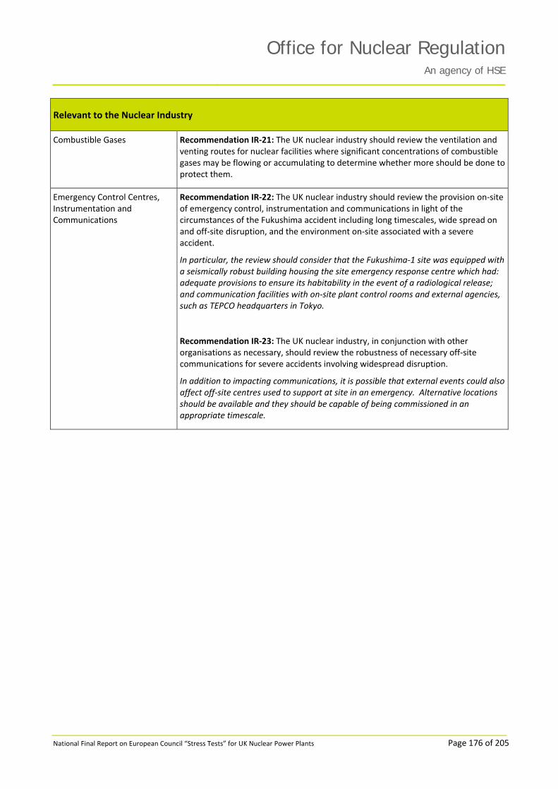
Office for Nuclear RegulationAn agency of HSE
National Final Report on European Council “Stress Tests” for UK Nuclear Power Plants Page 176 of 205
Relevant to the Nuclear Industry
Combustible Gases Recommendation IR‐21: The UK nuclear industry should review the ventilation and venting routes for nuclear facilities where significant concentrations of combustible gases may be flowing or accumulating to determine whether more should be done to protect them.
Emergency Control Centres, Instrumentation and Communications
Recommendation IR‐22: The UK nuclear industry should review the provision on‐site of emergency control, instrumentation and communications in light of the circumstances of the Fukushima accident including long timescales, wide spread on and off‐site disruption, and the environment on‐site associated with a severe accident.
In particular, the review should consider that the Fukushima‐1 site was equipped with a seismically robust building housing the site emergency response centre which had: adequate provisions to ensure its habitability in the event of a radiological release; and communication facilities with on‐site plant control rooms and external agencies, such as TEPCO headquarters in Tokyo.
Recommendation IR‐23: The UK nuclear industry, in conjunction with other organisations as necessary, should review the robustness of necessary off‐site communications for severe accidents involving widespread disruption.
In addition to impacting communications, it is possible that external events could also affect off‐site centres used to support at site in an emergency. Alternative locations should be available and they should be capable of being commissioned in an appropriate timescale.

Office for Nuclear RegulationAn agency of HSE
National Final Report on European Council “Stress Tests” for UK Nuclear Power Plants Page 177 of 205
Relevant to the Nuclear Industry
Human Capabilities and Capacities
Recommendation IR‐24: The UK nuclear industry should review existing severe accident contingency arrangements and training, giving particular consideration to the physical, organisational, behavioural, emotional and cultural aspects for workers having to take actions on‐site, especially over long periods. This should take account of the impact of using contractors for some aspects on‐site such as maintenance and their possible response.
This is a wide ranging recommendation and there are a number of aspects that need to be included:
a) the reviews need to acknowledge design differences between individual nuclear facilities and consider whether corporate Severe Accident Guidelines need to be customised;
b) adequacy of trained personnel numbers for long‐term emergencies, particularly for multi‐unit sites, and taking into account the potential impact of infrastructure damage and societal issues on the ability to mobilise large numbers of personnel;
c) the time windows for availability of off‐site support may be challenged hence the role of on‐site personnel may change, which has implications for procedures and training;
d) the review of Severe Accident Management Guidelines (SAMG) should consider not only critical safety functions prioritisation, but also whether and how SAMGs support any dynamic reprioritisation based on emerging information;
e) consideration should also be given to operator support requirements relating to tactical and strategic decision making; and
f) in addition to the acute phase of a severe accident, consideration also needs to be given to stabilisation, recovery and clean‐ up, and the personnel involved from the many organisations involved.
Recommendation FR‐11: The UK nuclear industry should continue to promote sustained high levels of safety culture amongst all its employees, making use of the National Skills Academy for Nuclear and other schemes that promote “nuclear professionalism”.

Office for Nuclear RegulationAn agency of HSE
National Final Report on European Council “Stress Tests” for UK Nuclear Power Plants Page 178 of 205
Relevant to the Nuclear Industry
Safety Case Recommendation IR‐25: The UK nuclear industry should review, and if necessary extend, analysis of accident sequences for long‐term severe accidents. This should identify appropriate repair and recovery strategies to the point at which a stable state is achieved, identifying any enhanced requirements for central stocks of equipment and logistical support.
Recommendation IR‐25 is linked with Recommendation IR‐13. Combining these two recommendations means that we would expect industry to:
a) identify potential strategies and contingency measures for dealing with situations in which the main lines of defence are lost. Considerations might include, for example, the operator’s capability to undertake repairs and the availability of spares (capability includes the availability of personnel trained in the use of emergency equipment along with necessary supporting resources);
b) consider the optimum location for emergency equipment, so as to limit the likelihood of it being damaged by any external event or the effects of a severe nuclear accident;
c) consider the impact of potential initiating events on the utilisation of such equipment;
d) consider the need for remotely controlled equipment including valves; and
e) consider in the layout of the site effective segregation and bunding of areas where radioactive liquors from accident management may accumulate.
Regarding other aspects of Recommendation IR‐25, the industry needs to:
f) ensure it has the capability to analyse severe accidents to properly inform and support on‐site severe accident management actions and off‐site emergency planning. Further research and modelling development may be required;
g) ensure that sufficient severe accident analysis has been performed for all facilities with the potential for accidents with significant off‐site consequences, in order to identify severe accident management and contingency measures. Such measures must be implemented where reasonably practicable and staff trained in their use; and
h) examine how the continued availability of sufficient on‐site personnel can be ensured in severe accident situations, as well as considering how account can be taken of acute and chronic stress at both an individual and team level (this is linked to Recommendation IR‐24).
Recommendation FR‐1: All nuclear site licensees should give appropriate and consistent priority to completing Periodic Safety Reviews (PSR) to the required standards and timescales, and to implementing identified reasonably practicable plant improvements.
Recommendation FR‐4: The nuclear industry should ensure that adequate Level 2 Probabilistic Safety Analyses (PSA) are provided for all nuclear facilities that could have accidents with significant off‐site consequences and use the results to inform further consideration of severe accident management measures. The PSAs should consider a full range of external events including “beyond design basis” events and extended mission times.
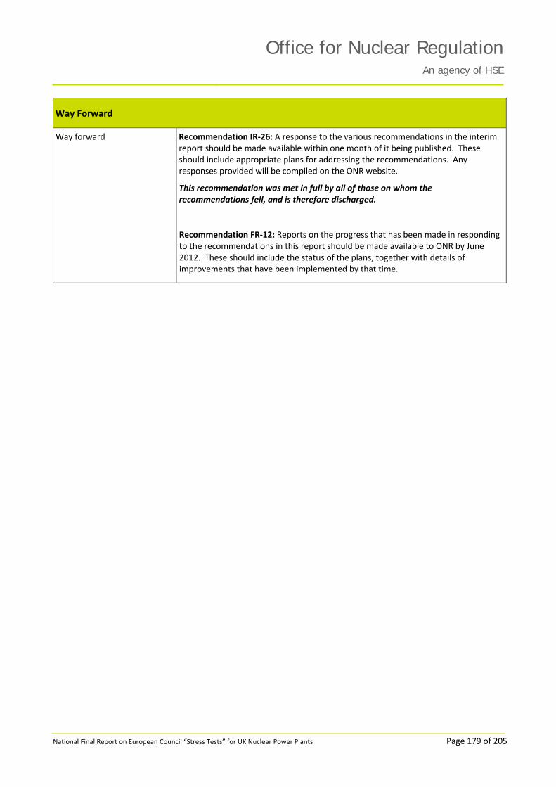
Office for Nuclear RegulationAn agency of HSE
National Final Report on European Council “Stress Tests” for UK Nuclear Power Plants Page 179 of 205
Way Forward
Way forward Recommendation IR‐26: A response to the various recommendations in the interim report should be made available within one month of it being published. These should include appropriate plans for addressing the recommendations. Any responses provided will be compiled on the ONR website.
This recommendation was met in full by all of those on whom the recommendations fell, and is therefore discharged.
Recommendation FR‐12: Reports on the progress that has been made in responding to the recommendations in this report should be made available to ONR by June 2012. These should include the status of the plans, together with details of improvements that have been implemented by that time.

Office for Nuclear RegulationAn agency of HSE
National Final Report on European Council “Stress Tests” for UK Nuclear Power Plants Page 180 of 205
ANNEX 2: EDF NGL STRESS TESTS CONSIDERATIONS
ID Chapter Consideration DNB HNB HPB HRA HYA HYB SZB TOR All Sites
All AGRs
CSA001 Chapter 2: Earthquake
Consider the need for a review of the totality of the required actions, and the way these might be influenced by the Emergency Arrangements (e.g. the need for a site muster, and the setting up of the Access Control Points), taking due account of the human factors issues.
DNB 2.1
HNB 2.1
HPB 2.1
HRA 2.1
HYA 2.1
HYB 2.1
TOR 2.1
CSA002 Chapter 2: Earthquake
Consider investigating whether the single long small bore pipe providing the make up to the decay store could be vulnerable to interaction hazards.
DNB 2.2
CSA003 Chapter 2: Earthquake
EDF Energy will consider reviewing the probability of consequential fire as a result of an earthquake.
DNB 2.4
HNB 2.2
HPB 2.2
HRA 2.2
HYA 2.2
HYB 2.2
TOR 2.2
CSA004 Chapter 2: Earthquake
Consideration should be given to the feasibility of enhancing the seismic capability of appropriate unqualified fire systems.
DNB 2.5
HNB 2.4
HPB 2.4
HRA 2.4
HYA 2.4
HYB 2.4
SZB 2.1
TOR 2.4
CSA005 Chapter 2: Earthquake
Consideration should be given to enhancing the robustness of pond cooling systems within the AGR fleet.
DNB 2.6
HNB 2.5
HPB 2.5
HRA 2.5
HYA 2.5
HYB 2.5
TOR 2.5
CSA006 Chapter 2: Earthquake
EDF Energy will consider conducting a review of the efficiency of the process for maintaining ongoing seismic qualification and consider whether improvements should be implemented.
HNB 2.3
HPB 2.3
HRA 2.3
HYA 2.3
HYB 2.3
TOR 2.3
CSA007 Chapter 2: Earthquake
The demands upon personnel to respond to beyond design basis events should be included within the review of the emergency response capabilities (considered further in chapter 6).
SZB 2.2
CSA008 Chapter 3: Flooding
Consider updating the safety case to reflect the latest assessment of the risk of flooding due to tsunamis at Dungeness B.
DNB 3.1

Office for Nuclear RegulationAn agency of HSE
National Final Report on European Council “Stress Tests” for UK Nuclear Power Plants Page 181 of 205
ID Chapter Consideration DNB HNB HPB HRA HYA HYB SZB TOR All Sites
All AGRs
CSA009 Chapter 3: Flooding
In line with Recommendation 10 of the ONR report, flooding studies have been initiated for all eight stations. These studies re‐evaluate the design basis flooding scenarios using the most recent data and taking account of climate change, they cover the period until 2035.
DNB 3.2
HNB 3.1
HPB 3.1
HRA 3.1
HYA 3.1
HYB 3.1
TOR 3.1
CSA010 Chapter 3: Flooding
In line with Recommendation 10 of the ONR Interim Report on the Japanese Earthquake and Tsunami Implications for the UK Nuclear Industry, flooding studies have been initiated for all eight stations. These studies re‐evaluate the design basis flooding scenarios using the most recent data and taking account of climate change, they cover the period until 2035.
SZB 3.1
CSA011 Chapter 3: Flooding
Consider reviewing whether the operators could complete all the tasks required prior to an extreme sea state or extreme rainfall if insufficient warning was given.
DNB 3.3
CSA012 Chapter 3: Flooding
Consider reviewing the exact water level at which essential plant located within buildings will fail due to flooding.
DNB 3.5
CSA013 Chapter 3: Flooding
Drainage of the site should be examined and the existing rainfall calculation revisited to highlight any margins. It should be ascertained whether the drainage would be compromised by a high sea state.
DNB 3.6
CSA014 Chapter 3: Flooding
Consideration should be given to the feasibility of additional temporary or permanent flood protection for essential safety functions where margins to flood levels are low.
DNB 3.7
CSA015 Chapter 3: Flooding
Consideration should be given to enhancing the robustness of dewatering capability, in particular focussing on independence from other systems.
DNB 3.8
HNB 3.3
HPB 3.5
HRA 3.3
HYA 3.3
HYB 3.5
TOR 3.5
CSA016 Chapter 3: Flooding
Consideration should be given to the feasibility of additional temporary or permanent flood protection for essential safety functions, for example the CW pumphouse.
HNB 3.2
HPB 3.4
HRA 3.2
HYA 3.2
HYB 3.4
TOR 3.4

Office for Nuclear RegulationAn agency of HSE
National Final Report on European Council “Stress Tests” for UK Nuclear Power Plants Page 182 of 205
ID Chapter Consideration DNB HNB HPB HRA HYA HYB SZB TOR All Sites
All AGRs
CSA017 Chapter 3: Flooding
Station should consider reviewing the output of this report and determine if any other local actions are required.
HPB 3.2
CSA018 Chapter 3: Flooding
Drainage for the site should be examined to explore the capability of beyond design basis events.
HPB 3.3
CSA019 Chapter 3: Flooding
The need for a formal reseal / repressurise case is currently being considered in a revision of the shutdown cooling safety case.
HYB 3.2
TOR 3.2
CSA020 Chapter 3: Flooding
The need to increase feed stocks to ensure they are sufficient for a 24 hour period is under review.
HYB 3.3
TOR 3.3
CSA021 Chapter 3: Flooding
Further mitigation against beyond design basis floods should be provided by for example, improvements to flood protection around the RUHS and electrical back‐up supplies.
SZB 3.2
CSA022 Chapter 4: Extreme Weather
Consideration should be given to reassessing the tornado hazard in light of recent studies which suggest the magnitude of the hazard may have been underestimated.
DNB 4.1
HNB 4.1
HPB 4.1
HRA 4.1
HYA 4.1
HYB 4.1
TOR 4.1
CSA023 Chapter 4: Extreme Weather
Consideration should be given to whether a snow loading hazard case is required and whether all aspects of the snow hazard such snow drifting have been considered.
DNB 4.2
HNB 4.4
HPB 4.2
HRA 4.2
HYA 4.3
HYB 4.2
TOR 4.3
CSA024 Chapter 4: Extreme Weather
Consider whether all credible combinations of hazards have been assessed.
DNB 4.3
HNB 4.5
HPB 4.3
HRA 4.3
HYA 4.4
HYB 4.3
SZB 4.2
TOR 4.4
CSA025 Chapter 4: Extreme Weather
Consideration should be given to evaluating the methodologies used to calculate the infrequent extreme ambient temperature and extreme wind event conditions and whether a fleet wide methodology should be adopted.
DNB 4.4
HNB 4.6
HPB 4.4
HRA 4.4
HYA 4.5
HYB 4.4
SZB 4.1
TOR 4.5

Office for Nuclear RegulationAn agency of HSE
National Final Report on European Council “Stress Tests” for UK Nuclear Power Plants Page 183 of 205
ID Chapter Consideration DNB HNB HPB HRA HYA HYB SZB TOR All Sites
All AGRs
CSA026 Chapter 4: Extreme Weather
Consideration should be given to defining the safety margin to equipment failure due to extreme wind, either directly or as a result of buildings failing.
DNB 4.5
HNB 4.7
HPB 4.5
HRA 4.5
HYA 4.6
HYB 4.5
TOR 4.6
CSA027 Chapter 4: Extreme Weather
Consideration should be given to defining the safety margin to equipment failure against extreme ambient temperature. This should include consideration of the consequences of loss of grid for an extended period and the ability to prevent freezing. Furthermore, consider the effects of extremely low ambient temperatures on building temperatures when both reactors are shutdown.
DNB 4.7
HNB 4.8
HPB 4.6
HRA 4.6
HYA 4.7
HYB 4.6
TOR 4.8
CSA028 Chapter 4: Extreme Weather
Consider reviewing whether comprehensive human factors assessments are required for operator actions undertaken during extreme weather conditions.
DNB 4.8
HNB 4.10
HPB 4.8
HRA 4.8
HYA 4.9
HYB 4.8
TOR 4.9
CSA029 Chapter 4: Extreme Weather
Consider reviewing the seasonal preparedness measures currently undertaken to identify areas to increase robustness.
DNB 4.9
HNB 4.11
HPB 4.9
HRA 4.9
HYA 4.10
HYB 4.9
SZB 4.3
TOR 4.10
CSA030 Chapter 4: Extreme Weather
Consideration should be given to all stations receiving site specific weather forecasts.
DNB 4.10
HNB 4.12
HPB 4.10
HRA 4.10
HYB 4.10
SZB 4.4
TOR 4.11
CSA031 Chapter 4: Extreme Weather
Consideration should be given to connecting the trace and tank heating systems to secure electrical systems.
DNB 4.11
CSA032 Chapter 4: Extreme Weather
Consideration should be given to the provision of additional station based robust means of personnel transport for extreme weather conditions.
DNB 4.12
HNB 4.13
HPB 4.11
HRA 4.11
HYA 4.11
HYB 4.11
SZB 4.5
TOR 4.12
CSA033 Chapter 4: Extreme Weather
A review of the programme of work in place to respond to the extreme wind hazard design basis methodology should be incorporated in to the next Periodic Safety Review. Any significant nuclear safety issues arising from the programme of work should be addressed as appropriate.
HNB 4.2

Office for Nuclear RegulationAn agency of HSE
National Final Report on European Council “Stress Tests” for UK Nuclear Power Plants Page 184 of 205
ID Chapter Consideration DNB HNB HPB HRA HYA HYB SZB TOR All Sites
All AGRs
CSA034 Chapter 4: Extreme Weather
Monitor and review the extreme ambient temperatures following the publication of the climate change adaptation report and consider these as part of plant life extension for all AGR stations.
HNB 4.3
HYA 4.2
TOR 4.2
CSA035 Chapter 4: Extreme Weather
Consideration should be given to the prioritisation of the ongoing production of the lightning and drought safety cases.
HNB 4.9
HPB 4.7
HRA 4.7
HYA 4.7
HYB 4.7
CSA036 Chapter 4: Extreme Weather
Consideration should be given to defining the safety margins to equipment failure against extreme ambient temperature.
TOR 4.7
CSA037a Chapter 5: Loss of Power and Heat Sink
Consideration should be given to the practicability of extending the availability of essential stocks for electrical supplies, by either providing additional on‐site storage facilities or additional means to replenish stocks to allow an extended operating period.
DNB 5.1
HPB 5.1
HRA 5.1
HYA 5.1
HYB 5.1
SZB 5.1
TOR 5.1
CSA037b Chapter 5: Loss of Power and Heat Sink
Consideration will be given to the practicability of extending safety case mission times by either providing additional on‐site storage facilities or additional diverse means to replenish stocks.
HNB 5.1
CSA038 Chapter 5: Loss of Power and Heat Sink
Consider making the re‐seal and re‐pressurisation equipment available independent of installed on‐site or off‐site AC power supplies.
DNB 5.2
CSA039 Chapter 5: Loss of Power and Heat Sink
Consideration should be given to reviewing the status of the arrangements to cover the event of SBO for [Station Name].
DNB 5.3
HRA 5.4
HYA 5.4
HYB 5.3
TOR 5.3
CSA040 Chapter 5: Loss of Power and Heat Sink
Consider providing resilient supplies for essential control and instrumentation and lighting functions.
DNB 5.4
HRA 5.5
CSA041 Chapter 5: Loss of Power and Heat Sink
Consideration should be given to provision of training, planning or pre‐engineering in order to improve mitigation measures.
DNB 5.5
HPB 5.3
HYA 5.5
HYB 5.6
SZB 5.3
TOR 5.6

Office for Nuclear RegulationAn agency of HSE
National Final Report on European Council “Stress Tests” for UK Nuclear Power Plants Page 185 of 205
ID Chapter Consideration DNB HNB HPB HRA HYA HYB SZB TOR All Sites
All AGRs
CSA042 Chapter 5: Loss of Power and Heat Sink
Consider providing transient analysis using the latest route covering the scenario with no available power or cooling to determine the timescales for prevention of fuel and structural damage.
DNB 5.6
HNB 5.2
HPB 5.4
HRA 5.7
HYA 5.6
HYB 5.7
TOR 5.7
CSA043 Chapter 5: Loss of Power and Heat Sink
Consideration should be given to the practicability of extending the availability of essential stocks of cooling water, by either providing additional on‐site storage facilities or additional means to replenish stocks to allow an extended operating period.
DNB 5.7
HPB 5.5
HRA 5.9HRA 5.12
HYA 5.8HYA 5.12
HYB 5.8
TOR 5.10
CSA044 Chapter 5: Loss of Power and Heat Sink
Consideration should be given to increasing the provision of off‐site back‐up equipment including: equipment to enable boiler feed; a supply of suitable inert gas for primary circuit cooling; electrical supplies for lighting, control and instrumentation.
DNB 5.8
HNB 5.4
HPB 5.6
HRA 5.13
HYA 5.13
HYB 5.9
SZB 5.5
TOR 5.14
CSA045 Chapter 5: Loss of Power and Heat Sink
To improve resilience of decay store cooling against loss of electrical power, consider possible enhancement options in respect to guidance to operators, fault recovery techniques, and improved understanding of credible consequences.
DNB 5.9
HNB 5.5
HPB 5.7
HRA 5.14
HYA 5.14
HYB 5.10
TOR 5.15
CSA046 Chapter 5: Loss of Power and Heat Sink
To improve resilience of pond cooling and make up against loss of electrical power, consider possible enhancement options in respect to guidance to operators, replenishment of lost pond water, and standalone pond cooling facilities having no dependence on any other station supplies or systems.
DNB 5.10DNB 5.12
HNB 5.6HNB 5.8
HPB 5.8HPB 5.10
HRA 5.15HRA 5.17
HYA 5.15HYA 5.17
HYB 5.11HYB 5.13
SZB 5.7
TOR 5.16TOR 5.18
CSA047 Chapter 5: Loss of Power and Heat Sink
To improve resilience of decay store cooling against the loss of the ultimate heat sink, consider possible enhancement options in respect to guidance to operators, fault recovery techniques, and improved understanding of credible consequences.
DNB 5.11
HNB 5.7
HPB 5.9
HRA 5.16
HYA 5.16
HYB 5.12
TOR 5.17
CSA048 Chapter 5: Loss of Power and Heat Sink
Consideration will be given to the practicability of extending safety case mission times by either providing additional on‐site storage facilities or additional diverse means to replenish stocks.
HNB 5.1

Office for Nuclear RegulationAn agency of HSE
National Final Report on European Council “Stress Tests” for UK Nuclear Power Plants Page 186 of 205
ID Chapter Consideration DNB HNB HPB HRA HYA HYB SZB TOR All Sites
All AGRs
CSA049 Chapter 5: Loss of Power and Heat Sink
Consider providing resilient supplies for essential control and instrumentation and lighting functions.
HPB 5.2
CSA050 Chapter 5: Loss of Power and Heat Sink
Consideration will be given to using diesel generators to power the emergency seawater pumps
HRA 5.2
HYA 5.2
CSA051 Chapter 5: Loss of Power and Heat Sink
Consideration will be given to carrying out a compatibility check to asses whether or not GT fuel can be used for BUCS pumps.
HRA 5.3
HYA 5.3
CSA052 Chapter 5: Loss of Power and Heat Sink
Consideration should be given to providing Emergency Plug‐in Points for portable diesel generators and mobile air compressors.
HRA 5.6
CSA053 Chapter 5: Loss of Power and Heat Sink
Consider whether the on‐site installation of additional, diverse, permanently installed AC power generators would be appropriate to ensure provision of power to essential systems for an extended mission time, for example 72 hours.
HRA 5.8
HYA 5.7
TOR 5.8
CSA054 Chapter 5: Loss of Power and Heat Sink
Any relevant operational experience from the recent Torness jellyfish drum screen blockage should be considered at [Station Name] once it becomes available.
HRA 5.10
HYA 5.9
TOR 5.11
CSA055 Chapter 5: Loss of Power and Heat Sink
Consider establishing the amount of additional water stocks that would be required to be held to allow an extended operating period of 72 hours to be claimed for the EBFS, and establish whether realistic options for storage of such stocks are available.
HRA 5.11
HYA 5.10
TOR 5.12
CSA056 Chapter 5: Loss of Power and Heat Sink
The disused Trimpell tanks could be completely removed and replaced with more modern and larger water storage tanks to provide extra towns‐water reserves to both Heysham 1 and 2.
HYA 5.11

Office for Nuclear RegulationAn agency of HSE
National Final Report on European Council “Stress Tests” for UK Nuclear Power Plants Page 187 of 205
ID Chapter Consideration DNB HNB HPB HRA HYA HYB SZB TOR All Sites
All AGRs
CSA057 Chapter 5: Loss of Power and Heat Sink
The potential for improving redundancy, reliability and ease of installation of the BUEFS should be considered.
HYB 5.2
CSA058 Chapter 5: Loss of Power and Heat Sink
The potential for improving redundancy, reliability and ease of connection of the BUEFS should be considered, including means for simplify and improve certainty of the connection / establishment of the BUEFS.
TOR 5.2
CSA059 Chapter 5: Loss of Power and Heat Sink
Consider whether additional means could usefully be installed in order to extend the formally claimed battery mission time by some margin.
HYB 5.4
TOR 5.4
CSA060 Chapter 5: Loss of Power and Heat Sink
Consider providing resilient supplies for essential control and instrumentation and lighting functions (fixed and portable) for all relevant areas of plant on site.
HYB 5.5
TOR 5.5
CSA061 Chapter 5: Loss of Power and Heat Sink
Consider whether additional means could usefully be installed to extend current battery capacity and supply.
SZB 5.2
CSA062 Chapter 5: Loss of Power and Heat Sink
For beyond design basis faults related to SBO, several specific potential enhancements have been identified and their practicability should be assessed.
SZB 5.4
CSA063 Chapter 5: Loss of Power and Heat Sink
For beyond design basis faults relating to the provision of water, several specific potential enhancements have been identified and their practicability should be assessed.
SZB 5.6
CSA064 Chapter 5: Loss of Power and Heat Sink
Consider providing a seismically qualified fire hydrant main. TOR 5.9

Office for Nuclear RegulationAn agency of HSE
National Final Report on European Council “Stress Tests” for UK Nuclear Power Plants Page 188 of 205
ID Chapter Consideration DNB HNB HPB HRA HYA HYB SZB TOR All Sites
All AGRs
CSA065 Chapter 5: Loss of Power and Heat Sink
The current robustness and maintenance of the plant is compliant with its design basis for loss of the ultimate heat sink. However, steps to improve the resilience of the plant following a beyond design basis event should be considered.
TOR 5.13
CSA066 Chapter 6: Severe Accident Management
Alignment of Dungeness B with generic role profile for responding ACP teams would enhance their resilience due to an increase in skills available.
DNB 6.1
CSA067 Chapter 6: Severe Accident Management
EDF Energy will consider how lessons identified from Japan and credible beyond design basis events can be reflected in our facilities, procedures, training and exercise programmes. Utilising experience from other emergency response organisations and the military, EDF will consider enhancement of its staff welfare, human factors and emotional aspects associated with emergency response.
DNB 6.2
HNB 6.1
HPB 6.2
HRA 6.1
HYA 6.1
HYB 6.1
SZB 6.1
TOR 6.1
CSA068 Chapter 6: Severe Accident Management
EDF Energy will consider further resilience enhancements to its equipment and critical supplies which take onboard lessons of extendibility and issues that prolonged events could present. Extensive work has already begun to highlight updates to equipment, its location and deployment.
DNB 6.3
HNB 6.2
HPB 6.3
HRA 6.3
HYA 6.4
HYB 6.4
SZB 6.3
TOR 6.2
CSA069 Chapter 6: Severe Accident Management
EDF Energy to consider enhancing current telephony and communications systems to increase levels of resilience of key technological components based on learning from Japan.
DNB 6.4
HNB 6.3
HPB 6.4
HRA 6.4
HYA 6.5
HYB 6.5
SZB 6.5
TOR 6.3
CSA070 Chapter 6: Severe Accident Management
EDF Energy will consider a review of its mobile facilities and the resilience of equipment contained within.
DNB 6.5
HNB 6.4
HPB 6.5
HRA 6.5
HYA 6.6
HYB 6.6
SZB 6.6
TOR 6.4
CSA071 Chapter 6: Severe Accident Management
EDF Energy should consider reviewing existing arrangements to ensure the principles of extendibility are adhered to.
DNB 6.6
HNB 6.5
HPB 6.6
HRA 6.6
HYA 6.9
HYB 6.9
SZB 6.7
TOR 6.5

Office for Nuclear RegulationAn agency of HSE
National Final Report on European Council “Stress Tests” for UK Nuclear Power Plants Page 189 of 205
ID Chapter Consideration DNB HNB HPB HRA HYA HYB SZB TOR All Sites
All AGRs
CSA072 Chapter 6: Severe Accident Management
Further mitigation against beyond design basis accidents could be provided by additional emergency backup equipment. This equipment could be located at an appropriate off‐site location close to the station to provide a range of capability to be deployed in line with initial post‐event assessment. This equipment may include the following capabilities:
Electrical supplies for plant facilities.
Emergency command and control facilities including communications equipment.
Emergency response / recovery equipment.
Electrical supplies for lighting, control and instrumentation.
Robust means for transportation of above equipment and personnel to the site post‐event.
Equipment to provide temporary shielding and deal with waste arising from the event.
DNB 6.7
HNB 6.6
HPB 6.7
HRA 6.7
HYA 6.10
HYB 6.10
SZB 6.8
TOR 6.6
CSA073 Chapter 6: Severe Accident Management
EDF Energy to review the adequacy of training in the use of the SAGs and the feasibility of implementing the advice in real scenarios.
DNB 6.8
HNB 6.7
HPB 6.8
HRA 6.8
HYA 6.11
HYB 6.11
TOR 6.7
CSA074 Chapter 6: Severe Accident Management
EDF Energy should consider a review, extension and retraining for the SBERGs
DNB 6.9
HNB 6.8
HPB 6.9
HRA 6.10
HYA 6.12
HYB 6.12
TOR 6.8

Office for Nuclear RegulationAn agency of HSE
National Final Report on European Council “Stress Tests” for UK Nuclear Power Plants Page 190 of 205
ID Chapter Consideration DNB HNB HPB HRA HYA HYB SZB TOR All Sites
All AGRs
CSA075 Chapter 6: Severe Accident Management
Further mitigation against beyond design basis accidents should be provided by additional emergency backup equipment. This equipment should provide additional diverse means of ensuring robust, long‐term, independent supplies to the sites. This equipment should be located at an appropriate off‐site location close to the station to provide a range of capability to be deployed in line with initial post‐event assessment. This equipment may include the following capabilities:
Equipment to enable pressure vessel cooling.
Supply of suitable inert gas for primary circuit cooling (AGR only).
Equipment to enable boiler feed.
Compressed air supply for decay tube cooling (AGR only).
Electrical supplies for primary circuit coolant circulation.
Equipment to enable fuel pond cooling.
Emergency command and control facilities including communications equipment.
Emergency response / recovery equipment.
Electrical supplies for lighting, control and instrumentation.
Water supplies for cooling from non‐potable sources.
Robust means for transportation of above equipment and personnel to the site post‐event.
DNB 6.10
HNB 6.9
HPB 6.10
HRA 6.9
HYA 6.13
HYB 6.13
TOR 6.9

Office for Nuclear RegulationAn agency of HSE
National Final Report on European Council “Stress Tests” for UK Nuclear Power Plants Page 191 of 205
ID Chapter Consideration DNB HNB HPB HRA HYA HYB SZB TOR All Sites
All AGRs
CSA076 Chapter 6: Severe Accident Management
Further mitigation against beyond design basis accidents should be provided by additional emergency backup equipment. This equipment should provide additional diverse means of ensuring robust, long‐term, independent supplies to the sites. This equipment should be located at an appropriate off‐site location close to the station to provide a range of capability to be deployed in line with initial post‐event assessment. This equipment may include the following capabilities:
Equipment to enable containment cooling.
Equipment to enable steam generator feedwater.
Electrical supplies for primary circuit make‐up.
Equipment to enable fuel pond cooling.
Emergency command and control facilities including communications equipment.
Emergency response / recovery equipment.
Electrical supplies for lighting, control and instrumentation.
Water supplies for cooling from non‐potable sources.
Robust means for transportation of above equipment and personnel to the site post‐event.
SZB 6.10

Office for Nuclear RegulationAn agency of HSE
National Final Report on European Council “Stress Tests” for UK Nuclear Power Plants Page 192 of 205
ID Chapter Consideration DNB HNB HPB HRA HYA HYB SZB TOR All Sites
All AGRs
CSA077 Chapter 6: Severe Accident Management
Consideration should be given to providing further mitigation against beyond design basis accidents by the provision of additional emergency backup equipment. This equipment could provide additional diverse means of ensuring robust, long‐term, independent supplies to the ponds. This equipment could be located at an appropriate off‐site location close to the station to provide a range of capability to be deployed in line with initial post‐event assessment. This equipment may include the following capabilities:
Equipment to enable fuel pond cooling.
Emergency command and control facilities including communications equipment.
Emergency response / recovery equipment.
Electrical supplies for lighting, control and instrumentation.
Water supplies for cooling from non‐potable sources.
Robust means for transportation of above equipment and personnel to the site post‐event.
It would be appropriate, if this equipment was developed and in any case to capture learning from events in Japan to review and where necessary revise the documentation and training provided for severe accident management in the fuel route plant areas.
DNB 6.11
HNB 6.10
HPB 6.11
HRA 6.11
HYA 6.14
HYB 6.14
TOR 6.10

Office for Nuclear RegulationAn agency of HSE
National Final Report on European Council “Stress Tests” for UK Nuclear Power Plants Page 193 of 205
ID Chapter Consideration DNB HNB HPB HRA HYA HYB SZB TOR All Sites
All AGRs
CSA078 Chapter 6: Severe Accident Management
Consideration should be given to providing further mitigation against beyond design basis accidents by the provision of additional emergency backup equipment. This equipment could provide additional diverse means of ensuring robust, long‐term, independent supplies to the ponds. This equipment could be located at an appropriate off‐site location close to the station to provide a range of capability to be deployed in line with initial post‐event assessment. This equipment may include the following capabilities:
Equipment to enable fuel pond cooling.
Emergency command and control facilities including communications equipment.
Emergency response / recovery equipment.
Electrical supplies for lighting, control and instrumentation.
Water supplies for cooling from non‐potable sources.
Robust means for transportation of above equipment and personnel to the site post‐event.
Installation of a radiation hardened camera with infra‐red capability in the fuel pond area to aid remote inspection of the fuel pond in fuel pond severe accidents.It would be appropriate, if this equipment was developed and in any case to capture learning from events in Japan to review and where necessary revise the documentation and training provided for severe accident management in the fuel route plant areas.
SZB 6.14
CSA079 Chapter 6: Severe Accident Management
There are currently no role specific details within the Emergency Scheme for the Fire Team Leader role in IRT. The development of this role detail is considered fundamental due to the requirement for a greater level of confidence / competence in this role during an emergency. In order to respond to the issue there is a need for specific training modules for this role, which is a role at Hinkley Point B station.
HPB 6.1

Office for Nuclear RegulationAn agency of HSE
National Final Report on European Council “Stress Tests” for UK Nuclear Power Plants Page 194 of 205
ID Chapter Consideration DNB HNB HPB HRA HYA HYB SZB TOR All Sites
All AGRs
CSA080 Chapter 6: Severe Accident Management
Complete Implementation of ECC Communication Co‐ordinator role. HRA 6.2
HYA 6.3
HYB 6.3
SZB 6.2
CSA081 Chapter 6: Severe Accident Management
Review in detail the benefits of having a co‐located ECC particularly focusing on the benefits that could be gained during Heysham 1 and 2 response to a multi unit event.
HYA 6.2
HYB 6.2
CSA082 Chapter 6: Severe Accident Management
Due to Heysham 1 and 2 utilising the adjacent sites ECC as a back up facility this could potentially result in vulnerabilities in the station response to a multi unit event. Establishment of an independent back up ECC should be considered.
HYA 6.7
HYB 6.7
CSA083 Chapter 6: Severe Accident Management
Heysham 1 and 2 to carry out a review of equipment and where possible align to allow for ease of use during an emergency. Equipment logs and location should be kept in both stations ECC to allow emergency responders to quickly identify and access equipment as needed. Where possible equipment should be kept in diverse locations to increase the probability of access.
HYA 6.8
HYB 6.8
CSA084 Chapter 6: Severe Accident Management
Ensure learning from Periodic Safety Review is incorporated into the emergency arrangements where appropriate.
SZB 6.4

Office for Nuclear RegulationAn agency of HSE
National Final Report on European Council “Stress Tests” for UK Nuclear Power Plants Page 195 of 205
ID Chapter Consideration DNB HNB HPB HRA HYA HYB SZB TOR All Sites
All AGRs
CSA085 Chapter 6: Severe Accident Management
Further mitigation against beyond design basis accidents could be provided by reviewing the feasibility of enhancing the plant design. These enhancements may include the following measures:
Installing a filtered containment venting system (FVC).
Installing passive autocatalytic hydrogen recombiners to mitigate against hydrogen risk especially post‐RB failure (or prior to containment venting).
Installing quick hook‐up points on the containment building fire suppression system to allow a flexible solution of containment water injection into containment.
SZB 6.9
CSA086 Chapter 6: Severe Accident Management
Once a strategy for back‐up equipment has been finalised consideration should be given to a review of the SOI 8 series.
SZB 6.11
CSA087 Chapter 6: Severe Accident Management
Review the severe accident mitigation procedure against best practice for Westinghouse plants and benchmark against severe accident procedures for French PWRs, specifically in terms of consistency of the procedure, priority of recovery actions and their feasibility of operation.
SZB 6.12
CSA088 Chapter 6: Severe Accident Management
Consideration should be given to reviewing whether any airborne release from a severe accident in the fuel pond would affect the habitability of the MCR.
SZB 6.13

Office for Nuclear RegulationAn agency of HSE
National Final Report on European Council “Stress Tests” for UK Nuclear Power Plants Page 196 of 205
ANNEX 3: MAGNOX LTD STRESS TESTS CONSIDERATIONS
Considerations
Chap
elcross
Dungeness A
Oldbury
Sizewell A
Wylfa
All Magnox Ltd
sites
M1 Consideration will be given to enhancing the methods and equipment for primary pressure circuit sealing. 1 1
M2 Consideration will be given to increasing the resilience of the Back‐Up Feed System. 2
M3 Consideration will be given to increasing the resilience of the back‐up feed systems and tertiary feed systems. 2
M4 Consideration will be given to increasing the resilience of the on‐site electrical system. 3 3
M5 Consideration will be given to providing a facility for the injection of nitrogen to support reactor hold‐down. 4 4
M6 Consideration will be given to enhancing the resilience of plant monitoring systems. 5 5
M7 Consideration will be given to enhancing the availability of beyond design basis equipment. 1 1 6 1 6
M8 Consideration will be given to providing further equipment to facilitate operator access around the Site. 2 2 7 2 7
M9 Consideration will be given to reinforcing the training for staff who may be required to respond to extreme events. 8 8
M10 Consideration will be given to enhancing on site arrangements for command, control and communications. 3 3 9 3 9
M11 Consideration will be given to providing additional stocks of consumables for plant and personnel. 10 10
M12 Consideration will be given to updating and enhancing severe accident management guidance. 4 4 11 4 11
M13 Consideration will be given to enhancing the resilience of spent fuel pond equipment to severe events. 5 12 5
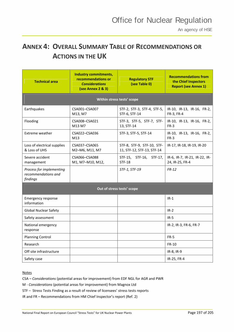
Office for Nuclear RegulationAn agency of HSE
National Final Report on European Council “Stress Tests” for UK Nuclear Power Plants Page 197 of 205
ANNEX 4: OVERALL SUMMARY TABLE OF RECOMMENDATIONS OR
ACTIONS IN THE UK
Technical area
Industry commitments, recommendations or
Considerations (see Annex 2 & 3)
Regulatory STF (see Table 0)
Recommendations from the Chief Inspectors Report (see Annex 1)
Within stress tests’ scope
Earthquakes CSA001–CSA007 M13, M7
STF‐2, STF‐3, STF‐4, STF‐5, STF‐6, STF‐14
IR‐10, IR‐13, IR‐16, FR‐2, FR‐3, FR‐4
Flooding CSA008–CSA021 M13 M7
STF‐3, STF‐5, STF‐7, STF‐13, STF‐14
IR‐10, IR‐13, IR‐16, FR‐2, FR‐3
Extreme weather CSA022–CSA036 M13
STF‐3, STF‐5, STF‐14 IR‐10, IR‐13, IR‐16, FR‐2, FR‐3
Loss of electrical supplies & Loss of UHS
CSA037–CSA065 M2–M6, M11, M7
STF‐8, STF‐9, STF‐10, STF‐11, STF‐12, STF‐13, STF‐14
IR‐17, IR‐18, IR‐19, IR‐20
Severe accident management
CSA066–CSA088 M1, M7–M10, M12,
STF‐15, STF‐16, STF‐17, STF‐18
IR‐6, IR‐7, IR‐21, IR‐22, IR‐24, IR‐25, FR‐4
Process for implementing recommendations and findings
STF‐1, STF‐19 FR‐12
Out of stress tests’ scope
Emergency response information
IR‐1
Global Nuclear Safety IR‐2
Safety assessment IR‐5
National emergency response
IR‐2, IR‐3, FR‐6, FR‐7
Planning Control FR‐5
Research FR‐10
Off site infrastructure IR‐8, IR‐9
Safety case IR‐25, FR‐4
Notes
CSA – Considerations (potential areas for improvement) from EDF NGL for AGR and PWR
M ‐ Considerations (potential areas for improvement) from Magnox Ltd
STF – Stress Tests Finding as a result of review of licensees’ stress tests reports
IR and FR – Recommendations from HM Chief Inspector’s report (Ref. 2)

Office for Nuclear RegulationAn agency of HSE
National Final Report on European Council “Stress Tests” for UK Nuclear Power Plants Page 198 of 205
81
REFERENCES ONR Report: Japanese Earthquake and tsunami: Implications for the UK nuclear industry HM
Chief Inspector of Nuclear Installations’ Interim Fukushima Report Office for Nuclear Regulation 18 May 2011, www.hse.gov.uk/nuclear/fukushima/interim‐report.pdf
2 ONR Report: Japanese earthquake and tsunami: Implications for the UK nuclear industry ‐ Final Report, 11 October 2011, www.hse.gov.uk/nuclear/fukushima/final‐report.pdf
3
4
5
6
7
IAEA International Fact Finding Expert Mission of the Fukushima Dai‐Ichi NPP Accident Following the Great East Japan Earthquake and Tsunami: 24 May – 2 June 2011 IAEA Mission Report
Report of the Japanese Government to the IAEA Ministerial Conference on Nuclear Safety – The Accident at TEPCO’s Fukushima Nuclear Power Stations Nuclear Emergency Response Headquarters, Government of Japan June 2011
Second Report of the Japanese Government to the IAEA – The Accident at TEPCO’s Fukushima Nuclear Power Stations, September 2011
European Nuclear Safety Regulators Group: Stress tests specification March 2011
ONR Report: European Council “Stress Tests” for UK Nuclear Power Plants, National Progress Report, 15 September 2011, www.hse.gov.uk/nuclear/fukushima/stress‐tests.pdf
8 Safety Assessment Principles for Nuclear Facilities 2006 Edition Revision 1 HSE January 2008 www.hse.gov.uk/nuclear/saps/saps2006.pdf
9
10
11
12
13
14
15
16
17
18
19
20
EDF Energy Nuclear Generation Comprehensive Safety Assessment – Dungeness B, Rev 000, 31 October 2011
EDF Energy Nuclear Generation Comprehensive Safety Assessment – Hinkley Point B, Rev 000, 31 October 2011
EDF Energy Nuclear Generation Comprehensive Safety Assessment – Hunterston B, Rev 000, 31 October 2011
EDF Energy Nuclear Generation Comprehensive Safety Assessment – Heysham 1, Rev 000, 31 October 2011
EDF Energy Nuclear Generation Comprehensive Safety Assessment – Hartlepool, Rev 000, 31 October 2011
EDF Energy Nuclear Generation Comprehensive Safety Assessment – Heysham 2, Rev 000, 31 October 2011
EDF Energy Nuclear Generation Comprehensive Safety Assessment – Torness, Rev 000, 31 October 2011
EDF Energy Nuclear Generation Comprehensive Safety Assessment – Sizewell B, Rev 000, 31 October 2011
Magnox Ltd Wylfa: Response to EU Stress tests following the events at Fukushima Japan, 31 October 2011
Magnox Ltd Oldbury: Response to EU Stress tests following the events at Fukushima Japan, 31 October 2011
Magnox Ltd Sizewell A: Response to EU Stress tests following the events at Fukushima Japan, 31 October 2011
Magnox Ltd Dungeness A: Response to EU Stress tests following the events at Fukushima Japan, 31 October 2011

Office for Nuclear RegulationAn agency of HSE
National Final Report on European Council “Stress Tests” for UK Nuclear Power Plants Page 199 of 205
21
22
23
Magnox Ltd Chapelcross: Response to EU Stress tests following the events at Fukushima Japan, 31 October 2011
Sellafield Ltd Calder Hall Report on the ENSREG Stress Tests Following the Japanese Earthquake and Tsunami, 31 October 2011
Dounreay Site Restoration Ltd DSRL Response to ENSREG Stress tests, A submission to the Office for Nuclear Regulation, 31 October 2011
While every effort has been made to ensure the accuracy of the public references listed in this report, their future availability cannot be guaranteed.

Office for Nuclear RegulationAn agency of HSE
National Final Report on European Council “Stress Tests” for UK Nuclear Power Plants Page 200 of 205
9 GLOSSARY AND ABBREVIATIONS AC Alternating current
ACP Access control point
AFS Additional feed system
AGR Advanced gas‐cooled reactor
AIC Alternative indication centre
ALARP As low as reasonably practicable
AOD Above ordnance datum
ASME American Society of Mechanical Engineers
Beyond design basis In a beyond design basis event, the conditions are more severe than in a design basis event.
BST Buffer storage tube
BUCS Back‐up cooling system
BUECW Back‐up essential cooling water
BUEFS Back‐up emergency feed system
BUFS Back‐up feed system
BWR Boiling water reactor
C&I Control and instrumentation
CO2 Carbon dioxide
CCR Central control room
CEGB Central Electricity Generating Board
CESC Central emergency support centre
Cliff‐edge A cliff‐edge effect is a small change in a parameter that leads to a disproportionate increase in consequences.
COBR Cabinet office briefing room
Consideration A Consideration (in italic with a capital) is an indication of how the licensees currently plan to take forward potential improvements into a decision‐making process. Note that a Consideration is not a commitment to undertake a specific activity or purchase specific equipment.
CVCS Chemical and volume control system
DBA Design basis analysis
DBE Design basis earthquake
DBF Design basis flood
Design basis The range of conditions and events that should be explicitly taken into account in the design of the facility, according to established criteria, such that the facility can withstand them without exceeding authorised limits by the planned operation of safety system.
DC Direct current

Office for Nuclear RegulationAn agency of HSE
National Final Report on European Council “Stress Tests” for UK Nuclear Power Plants Page 201 of 205
DEPZ Detailed emergency planning zone
DFR Dounreay fast reactor
DNB Dungeness B
DSRL Dounreay Site Restoration Ltd
EBFS Emergency boiler feed system
EBS Emergency boration system
EC European Council
ECC Emergency control centre
ECCS Emergency core cooling system
ECW Essential cooling water
EDF Electricité de France
EDF NGL EDF Energy Nuclear Generation Ltd
EDG Emergency diesel generator
EES Essential electrical system
EIC Emergency indication centre
ENSREG European Nuclear Safety Regulators Group
EOS Electrical overlay system
ESD Enhanced shutdown system
ESWS Emergency service water system
FWS Feed water system
GL Guardlines
GT Gas‐turbine
H&V Heating and ventilation
HNB Hunterston B
HPB Hinkley Point B
HPME High‐pressure melt ejection
HRA Hartlepool
HSE Health and Safety Executive
HSWA74 Health and safety at work etc. Act 1974
HVAC Heating, ventilating and air conditioning
HYA Heysham 1
HYB Heysham 2
IAEA International Atomic Energy Agency
IFDF Irradiated fuel dismantling facility
ILW Intermediate level radioactive waste
INES International nuclear and radiological event scale

Office for Nuclear RegulationAn agency of HSE
National Final Report on European Council “Stress Tests” for UK Nuclear Power Plants Page 202 of 205
INPO Institute of Nuclear Power Operations
IPSART International PSA review team
LC Licence condition
LLW Low level radioactive waste
LOCA Loss of coolant accident
LOOP Loss of off‐site power
LPBUCS Low pressure back‐up cooling system
LTSR Long term safety review
Magnox Magnesium non‐oxidising
MCR Main control room
MCW Main cooling water
ML The Richter local magnitude ML is defined to be used for local earthquakes, and is the magnitude scale used by British Geological Survey when locating UK earthquakes.
MS Maintenance schedule
MTPAS Mobile privileged access scheme
MWe MegaWatt electric: unit of power relating to the power produced downstream to the turbines and the alternator.
MWth MegaWatt thermal: unit of power relating to the power produced by the reactor, upstream to the turbines and alternator.
NIA65 Nuclear Installations Act 1965
NIAS Nuclear industry airwave service
Nile A unit of reactivity. The reactivity measures the capability of a reactor to maintain its level of nuclear reactions.
NIS Nitrogen injection system
NPP Nuclear power plant
NSC Nuclear Safety Committee
ONR Office for Nuclear Regulation (formerly the Nuclear Directorate of the HSE)
OPEX Operational experience
pa per annum
PCPV Pre‐stressed concrete pressure vessel
PFR Prototype fast reactor
PGA Peak ground acceleration
PML Principia Mechanica Ltd
PPCS Ponds package cooler system
PSA Probabilistic safety analysis
PSD Primary shutdown system
PSR Periodic safety review

Office for Nuclear RegulationAn agency of HSE
National Final Report on European Council “Stress Tests” for UK Nuclear Power Plants Page 203 of 205
PSR2 Second round of PSR
PVCS Pressure vessel cooling system
PWR Pressurised water reactor
RCCA Rod cluster control assemblies
RCS Reactor coolant system
REIC Remote emergency indication Centre
REPPIR Radiation (emergency preparedness and public information) Regulations
RHRS Residual heat removal system
RUHS Reserve ultimate heat sink
Safety margins Safety margins identify the gap between a considered situation and the threshold situation beyond which the probability of accident is not tolerable.
SAG Severe accident guidelines
SAGE Scientific Advisory Group for Emergencies
SAMG Severe accident management guideline
SAP Safety assessment principle(s) (HSE)
SBERG Symptom based emergency response guidelines
SBO Station blackout
SCC Strategic coordination centre
SCE/SM Shift Charge Engineer / Shift Manager
Severe accident A fault sequence which leads either to consequences exceeding highest radiological doses given in the basic safety level – on‐site: 500mSv, off‐site: 100mSv for initiating fault frequencies less than 10‐4 per annum – or to a substantial unintended relocation of radioactive material within the facility which places a demand on the integrity of the remaining physical barriers.
SHWP Seismic Hazard Working Party
Single failure criterion This criterion sets that, during any normally permissible state of plant availability, no single random failure, assumed to occur anywhere within the systems provided to secure a safety function, should prevent the performance of that safety function.
SNUPPS Standardised nuclear unit power plant system
SOI Station operating instructions
SRV Safety relief valve
SSC Structure, system and component important for safety
SSHAC Senior Seismic Hazard Analysis Committee
STF Stress tests finding
Stress tests The stress tests are summarised as a targeted reassessment of the relevant safety margins of NPPs in the light of events which occurred at Fukushima: extreme natural events challenging the plant safety functions and leading to a severe accident.
SZB Sizewell B

Office for Nuclear RegulationAn agency of HSE
National Final Report on European Council “Stress Tests” for UK Nuclear Power Plants Page 204 of 205
TAG Technical assessment guide(s) (HSE)
TAP Technical Advisory Panel
TFS Tertiary feed system
TIIMS The incident information management system
TOR Torness
UO2 Uranium dioxide
URS Uniform risk spectra
Walkdown An on‐site systematic review of a structure, system or components (SSC) by a small team of suitable, qualified and experienced persons to review the SSC capability to withstand defined hazards.
WANO World Association of Nuclear Operators
WENRA Western European Nuclear Regulators’ Association

Office for Nuclear RegulationAn agency of HSE
National Final Report on European Council “Stress Tests” for UK Nuclear Power Plants Page 205 of 205
10
CONTACTS HM Chief Inspector of Nuclear Installations Office for Nuclear Regulation Redgrave Court Merton Road Bootle Merseyside L20 7HS www.hse.gov.uk
email: [email protected]
For information about health and safety visit www.hse.gov.uk. You can view HSE guidance online and order priced publications from the website. HSE priced publications are also available from bookshops. 2011/632875