Embed Size (px)
Citation preview

DESIGN, CONSTRUCTION AND MAINTENANCE OF NETBALL FACILITIES
National Facilities Policy
VERSION 02: MARCH 2016
Following is a National Facilities Policy for netball in Australia. The guidelines within provide clarity on roles and responsibilities for the provision of community netball facilities in this country.

CONTENTS
1
INTRODUCTION 02
1.1 Background 02
1.2 Policy Development 02
2
STRATEGIC CONTEXT 03
2.1 Netball Australia Strategic PLan 03
3
POLICY OBJECTIVES & PRINCIPLES 04
3.1 Policy Objectives 04
3.2 Guiding Principles 04
4
A NATIONAL FRAMEWORK 05
4.1 Roles & Responsibilities 05
5
FACILITY GUIDANCE 06
5.1 Background 06
5.2 Management Plan & Design Brief 06
6
FACILITY DEVELOPMENT PROCESS 07
6.1 Overview 07
6.2 Needs Assessment 07
6.3 Concept & Feasibility 07
6.4 Funding 07
6.5 Project Delivery 08
6.6 Management & Operation 08
7
TECHNICAL MANUAL 09

1
INTRODUCTION
1.1 BACKGROUND
Facilities play a vital role in the vibrancy of community sport. Proving access to high quality facilities that meet the needs and demands of netball is a critical component of growing and sustaining participation as well as supporting the sustainability of associations, leagues and clubs. Netball facilities across Australia are owned and/or managed by a variety of organisations including local and state governments, schools and universities, church groups, netball associations and leagues as well as clubs.
Peak sporting organisations are increasingly taking a more hands on approach to facility planning and development including the formation of policy and strategy documents, along with tools and resources to assist key stakeholders in the planning and development process.
These peak sporting organisation are doing so in order to improve the consistency, quality and access to facilities with the ultimate aim of growing the sport.
Netball Australia wishes to provide stakeholders with an overarching policy that can assist in the planning and development of community netball facilities, ensuring the netballers of today and tomorrow can enjoy this great sport into the future.
1.2 POLICY DEVELOPMENT
The National Facilities Policy was developed in consultation with key stakeholders including Member Organisations, Associations, Leagues and Clubs as well as local and state governments.The process included the review of existing facility planning documentation such as state-wide master plans, technical manuals, and government publications to ascertain the current resources available to key stakeholders.
A number of facility visits were conducted along with interviews with local and regional associations to gain an appreciation of facility management challenges including programming and utilisation.
The process identified that there are a number of gaps in the provision of suitable publications and resources to support facility planning and development including:
• A facility planning and development framework and process
• State-wide master plans including hierarchy and preferred facility guidelines
• Technical manuals and guidance including court surfaces and lighting
Whilst the Policy will not address all the gaps in publications and resources (as other stakeholders also have a role to play) it will provide the overarching policy for facility planning and development along with technical guidelines that can be applied nationally.
NATIONAL FACILITIES POLICY02

03NATIONAL FACILITIES POLICY
2
STRATEGIC CONTEXT
2.1 NETBALL AUSTRALIA
STRATEGIC PLAN
VISION Everyone in Australia values their connection with netball.
We will know we have achieved our vision when:
• Everyone in Australia has an opportunity to be involved in netball in a way that brings them good health, recognition, achievement, enjoyment and a sense of belonging.
• Netball builds communities of healthy, confident and resilient girls and women through participation and world-class competition.
• Netball is a fun, social game that caters for Australia’s diverse population.
• Netball has a seat at the table and is a thought leader for sport, women and community issues.
• We retain world number one with female athletes who inspire everyone in Australia.
• ANZ Championship and international tests showcase outstanding sport entertainment and netball is a valued product for broadcasters.
• Netball is the vehicle by which corporate and government choose to reach women.
• We sustain a culture that preserves our heritage and celebrates women.
• Netball is known for outstanding leadership, governance and workforce opportunities.
Strategic Priorities 2014-2018• Position the sport so that it broadens the appeal
and increases the engagement with Australia’s diverse population.
• Invest in partners with a footprint that helps to extend netball’s connection with communities.
• Meet the demand for contemporary, consumable and convenient sport products.
• Use the NWC 2015 and CG 2018 to deliver a sustainable legacy for Australian netball.
GOAL: Vibrant Community SportObjective – Provide a range of products, competitions and events to grow and sustain participation.
Objective – Build the capacity of the netball workforce.
Objective – Increase netball’s engagement with Australia’s diverse population.
GOAL: The Netball TribeObjective – Develop a clear brand position and offering for all national products to take the game to more people.
Objective – Position the Australian Netball Diamonds as a leading sports brand.
Objective – Drive targeted communications with identified market segments via integrated marketing, social media and database strategy.
GOAL: World Number OneObjective – Identify and develop the next generation of high performance athletes.
Objective – Establish a pool of world class high performance coaches working in the Australian system.
Objective – Deliver a world class training environment to win milestone events.
Objective – Deliver an effective domestic and international competition program to prepare athletes for benchmark events.
Objective – Provide leadership that supports an aligned, coordinate and effective national system
GOAL: Financial SuccessObjective – Elevate the quality, value and management of our products to maximize core revenue streams, providing greater opportunities to our partners and stakeholders.
Objective – Manage financial efficiencies and a positive culture to risk.
Objective – Maximise the opportunity to grow revenues through participation and major event products.
GOAL: Inspired LeadershipObjective – Foster a unified, collaborative and aligned sport.
Objective – Adopt processes and systems to improve efficiencies and effectiveness across netball.
Objective – Preserve and protect netball’s heritage.
Objective – Netball impacts on the social, political, economic, education and health status of women and girls.

3
POLICY OBJECTIVES & PRINCIPLES
3.1 POLICY OBJECTIVES
The key objectives of the Policy are to:
• Support participation growth and sustainability
• Provide key stakeholders with guidance in facility planning and development
• Provide a technical manual that can be applied nationally
• Improve the overall consistency, quality and accessibility of netball facilities
3.2 GUIDING PRINCIPLES
Netball facility planning and development is to be focused on supporting the growth of the sport.
In order to do this, facilities will be planned and developed with consideration of the following guiding principles:
1 Strategic need, facility demand and participation growth opportunities
2 Accessibility and inclusion, catering for multiple formats of the sport
3 Maximising utilisation and improved programming
4 Best practice technical and design standards
5 Alignment with the needs of key stakeholders and partners
NATIONAL FACILITIES POLICY04

4
A NATIONAL FRAMEWORK
The Policy provides Netball in Australia with an overarching framework to guide facility planning and development.It has been developed with a specific focus on improving facility planning and development practices and providing guidance that can be applied nationally.
The development of consistent, high quality and accessible netball facilities requires involvement from key stakeholders including all levels of Netball as well as government:
4.1 ROLES & RESPONSIBILITIES
Each of the stakeholders has roles and responsibilities in the execution of the Policy:
05NATIONAL FACILITIES POLICY
Netball Australia Federal Government
Member Organisations
State / Territory Government
Associations, Leagues & Clubs
Local Government
Key Stakeholders
ORGANISATION ROLES & RESPONSIBILITIES
Netball Australia
• Develop policy that can be applied nationally to the benefit of all stakeholders. This includes facility planning and development process and technical guidance
• Support for funding applications for large scale projects with strategic benefit
• Federal government liaison
Member Organisations
• Undertake analysis of facility needs and develop specific plans and strategies to address these needs. This includes facility audits, state wide master plans, preferred facility guidelines and feasibility studies
• Funding applications for medium to large scale projects
• State and local government liaison
Associations, Leagues & Clubs
• Monitor and evaluate the performance of their existing facilities including the assessment of current condition and future needs
• Funding applications for small to medium scale projects
• Local government liaison
Federal Government
• Facilitate a strategic approach to the provision of sporting and active recreation infrastructure
• Investment in facilities
State/Territory Government
• Provide policy and strategic support to the planning and development of medium to large scale facilities
• Assessment of funding applications • Investment in facilities
Local Government
• Facility planning including assessment and prioritisation of local needs
• Facility management and operation including maintenance and capital upgrades
• Support for funding applications for small to large scale projects
• Investment in facilities

5
FACILITY GUIDANCE
5.1 BACKGROUND
The development of preferred facility guidelines is a practice that has been adopted by a number of sporting organisations. These guidelines provide very detailed facility design guidance including core and optional components of a facility along with proposed preferred square metre allowances or estimates for these components. The development of detailed preferred facility guidelines was contemplated as part of this Policy however it was determined that as the requirements of each state/territory vary widely, such a document would be difficult to develop and apply nationally.
Member Organisations may choose to develop such guidelines however must be cognisant that facilities should be planned and designed based on wider Netball considerations (as outline here) including facility needs, demand, intended use and programming specific to the local or regional area.
5.2 MANAGEMENT PLAN
& DESIGN BRIEF
In the planning of a new facility or the redevelopment of an existing facility, the role of the facility, its intended use and occupancy are important considerations that need to be taken into account. A management plan for the facility will detail how the facility will be used (i.e. competition, events, training, game development, high performance).
The management plan is then used to develop a design brief (functional requirements of the proposed facility). This is best developed with an architect.
In the development of the design brief, the following should be incorporated into the facility:
• Change rooms
• Umpires change rooms
• Public toilets (including accessible)
• Competition / Administration office
• First Aid room
• Kiosk/canteen
• Social area
• Storage
Other functionality such as kitchens, dedicated function space, meeting rooms, warm-up areas, spectator seating and amenities can be considered on a needs basis.
NATIONAL FACILITIES POLICY06

6
FACILITY DEVELOPMENT PROCESS
6.1 OVERVIEW
The development of a new facility or the redevelopment of an existing facility requires careful planning and due diligence to ensure that the project is a success.
When embarking on a facility development project, it is important to understand the steps involved from project inception to completion as this will ensure that fundamental considerations are taken into account and project objectives are prioritised.
There are five key stages in the planning and development of a new or redeveloped facility:
In each stage there are a number of tasks that should be completed prior to moving to the next stage. It is expected that specialist advice will be required throughout.
It is important to note the information provided here is not definitive and may vary subject to the nature and scale of the proposal or project. It is intended to be a guide and should be used as such.
6.2 NEEDS ASSESSMENT
The Needs Assessment is the first step in the development of a proposal, whether it is a new facility or the redevelopment of an existing facility.
A Needs Assessment will determine the scope of the proposal by clearly identifying what is the gap in the existing service offering.
As part of this, a number of key tasks should be undertaken:
• Establish vision and objectives• Review and assess existing facility provisions in the area• Undertake consultation with key stakeholders such as
participants, leagues, local government and other potential users
• Determine the facility need • Prepare development proposal
At the completion of this stage, the need will be determined and a decision can be made whether to move forward with the proposal.
6.3 CONCEPT & FEASIBILITY
The next stage in the process is Concept & Feasibility. It is in this stage that the proposal is further developed including a facility brief, preliminary concept plans and indicative cost estimates. This stage will also include consideration of management, operational revenues and expenses, and life cycle costs.
The key tasks that should be undertaken include:
• Undertake further consultation with key stakeholders
• Estimate key parameters including management, programs, services, usage and pricing
• Develop a facility requirements brief
• Prepare preliminary concept plan and capital cost estimate
• Undertake financial assessment including funding options
• Develop implementation plan including staging options
The extent of documentation will be determined by the audience whether that be internal, association or league, local or state government.
At the completion of this stage, the feasibility of the proposal will have been assessed and a decision can be made to revisit the proposal, progress as is, implement in stages or not move forward with the proposal.
6.4 FUNDING
Once it is determined that the proposal is feasible and a decision is made to proceed, funding will need to be committed to transition to a live project. Funding may come from a range of sources including local, state and federal governments, local community and the private sector.
In this stage, a number of key tasks should be undertaken:
• Confirm the project budget
• Develop a preferred funding model including project partners
• Prepare (if required) relevant funding applications
• Negotiate funding agreements
Once funding is secured, the proposal then transitions to a live project.
Needs Assessment1
Concept & Feasbility2
Funding3
Project Delivery4
Management & Operation5
07NATIONAL FACILITIES POLICY

6
FACILITY DEVELOPMENT PROCESS
6.5 PROJECT DELIVERY
Funding has been secured and now the project must be delivered. The Project Delivery stage has a design team being engaged and detailed design and contract documentation prepared. This stage also includes the appointment of a contractor for construction of the facility.
The key tasks in this stage should include:
• Prepare a Project Management Plan including project governance
• Appoint the design team including architect, engineers and other required specialists
• Undertake detailed design and prepare a detailed cost plan
• Seek relevant planning and statutory approvals
• Appoint contractor for construction
• Construction and commissioning of the facility
• Develop operations plans
Throughout the Project Delivery stage, progress should be monitored on a regular basis.
6.6 MANAGEMENT & OPERATION
Upon completion of the project and handover from the contractor, the new or redeveloped facility will become operational. The operations plans developed in the Project Delivery stage should be executed now.
Once operational, the key management tasks should include:
• Service delivery
• Facility operations and maintenance
• Risk management
• Ongoing evaluation of facility performance
• Planning for future needs
NATIONAL FACILITIES POLICY08
DESIGN, CONSTRUCTION AND MAINTENANCE OF NETBALL FACILITIES
Technical Manual
VERSION 01: JULY 2015

PRODUCED BY 2MH CONSULTING ON BEHALF OF NETBALL AUSTRALIA FOR THE DESIGN, CONSTRUCTION AND MAINTENANCE OF NETBALL FACILITIES © 2015
The following manual has been prepared by Netball Australia to help Clubs, Associations, local government, the education sector, contractors and others in the netball community to understand better the technical aspects of netball court design, construction & maintenance requirements.

CONTENTS
1
INTRODUCTION 14
2
COMPLIANCE 15
2.1 Compliance overview 15
2.2 Compliance – Summary details 16
2.3 Compliance – Court dimensions & run-offs in detail 19
2.4 Compliance – Further information 19
3
UNDERSTAND THE STEPS IN THE NETBALL COURT PROJECT JOURNEY 20
4
CONTACT YOUR LOCAL COUNCIL & STATE/TERRITORY MEMBER ORGANISATION 21
4.1 Local Council 21
4.2 Netball Member Organisation 21
5
INDEPENDENT FACILITY INSPECTION, AUDIT & WORKS RECOMMENDATION REPORT 22
6
SELECTING A SITE 23
6.1 Site selection overview 23
6.2 Site preference 23
6.3 Sites to avoid 23
6.4 Concept design 24
7
BUDGET & FUNDING 25
7.1 Budget overview 25
7.2 Cost estimates 25
7.3 Contingency 26
7.4 Funding 26
8
SITE INVESTIGATIONS 27
8.1 Geotechnical report/Soil report 27
8.2 Title survey 27
8.3 Service detections 28
8.4 Feature survey 28
9
DESIGN 29
9.1 Design overview 30
9.2 Base choice (Asphalt or concrete?) 31
9.3 Court layout 32
9.4 Court orientation 32
9.5 Line marking 33
9.6 Goal posts and padding 34
9.7 Lighting 35
9.7.1 Lighting standards 35
Netball lighting guidelines recommendations 36
Netball lighting play level classifications 36
Netball lighting recommendations – Outdoor netball (Non-televised) 36
Netball lighting recommendations – Indoor netball (Non-televised) 38
Netball lighting recommendations – Colour television (CTV) lighting 38
Netball lighting recommendations – Additional criteria 39
Netball lighting recommendations – Other lighting considerations 40
Netball lighting recommendations – Transitional arrangements 40
9.7.2 General lighting information 40
Getting started 40
Lamp types 41
Pole configuration and heights 42
Choice of lighting system 43
Illuminance 43
Uniformity 43
Light loss factors 43
Glare 43
Circuit switching 44
Obtrusive/Spill light standards 44
Maintenance of lighting 44
Lamp maintenance 44
Luminaires 44
Light towers 44
9.8 Fencing 45
9.9 Shelter, storage & seating 47
9.10 Inclusivity, accessibility & signage 48
9.11 Landscaping 49
9.12 Court surface 49
9.12.1 Acrylic surface 49
9.12.2 Acrylic hard court – non-cushion 51
9.12.3 Liquid applied cushion 51
9.12.4 Mat Laid cushion 52
9.12.5 Surface advantages and disadvantages 53
9.12.6 Indoor court flooring 57
CONTENTS
10
CHOOSING A CONTRACTOR 58
10.1 Get a quote 58
10.2 Obtain technical guidance 58
10.3 Prepare a technical specification & design package 58
10.4 Request tenders or quotes from the construction industry 59
10.5 ‘Compare apples with apples’ when choosing between tenderers 60
10.6 Ensure appropriate contracts and project acceptance 60
11
PROJECT MANAGEMENT 61
12
COURT CONSTRUCTION – PAVEMENT 62
12.1 Cut and fill 62
12.2 Pavement platform 62
12.3 Subgrade preparation 62
12.4 Sub-base preparation and compaction 63
12.5 Drainage 65
12.5.1 Good court surface drainage 65
12.5.2 Good drainage surrounding the pavement 65
12.5.3 Good sub-surface drainage surrounding the pavement 65
12.6 Tree root barriers 66
12.7 Concrete plinths 66
13
COURT CONSTRUCTION – COURT BASE 67
13.1 Factors to consider when deciding whether to use concrete or asphalt base 67
13.2 Asphalt base – also known as: Asphaltic concrete (AC), Hot mix, Tarmac 68
13.3 Concrete base – also known as: Reinforced concrete (RC) 70
13.3.1 Expansion joints 72
13.3.2 Proprietary metal formers or Toby joints 72
13.3.3 Cracker joints 72
13.3.4 Dowel joints 72
13.3.5 Saw cuts 72
13.3.6 Shrinkage cracks 72
13.3.7 Laitance 72
13.3.8 Efflorescence 73
13.3.9 Accelerators 73
13.4 Common base issues 73
13.4.1 Base issues introduction 73
13.4.2 Construction failures 74
13.4.3 Deterioration failures 74
13.4.4 Subsidence 74
13.4.5 Low spots or ‘bird baths’ 75
13.4.6 Surface and base cracks 76
13.4.7 Bare asphalt 79
13.4.8 Rust Stains/Pyrites 79
13.4.9 Conclusion 80
14
COURT CONSTRUCTION – COURT SURFACE 80
14.1 Acrylic surface application 80
14.1.1 Application on asphalt 80
14.1.2 Application on concrete 81
14.1.3 Two colour application 82
14.1.4 Drying requirements 82
14.1.5 Procedures to be avoided in applying acrylic coating material 82
14.2 Cushion acrylic installation 83
14.2.1 Cushion acrylic base preparation 83
14.2.2 Types of cushion acrylic surfaces 83
14.2.3 Liquid applied cushion systems 83
14.2.4 Installation of liquid applied cushion systems 83
14.2.5 Mat lay cushion 84
14.2.6 Installation of mat lay systems 84
14.3 Resurfacing 84
14.4 Surface & Court Repairs 87
14.4.1 Identifying & Patching Bird Baths/Ponding Areas 87
14.4.2 Area preparation 89
14.4.3 Application of patching material 89
14.4.4 Grinding patches 89
14.4.5 Crack repairs 89
14.4.6 Recommendation for large structural cracks 90
14.5 Court surface maintenance 91
14.5.1 Maintenance overview 91
14.5.2 Maintenance equipment 91
14.5.3 Maintenance recommendations 91
Dirt and debris 91
Drainage infrastructure 91
Food/drink, mould growth & tree/plant contamination 92
Specific contaminations: Wildlife droppings, shoe marks, chewing gum, oil and grease 92
Repairs 92
Drying the court surface after rain 92

CONTENTS
15
PROJECT COMPLETION OR HANDOVER 93
16
DEFECTS LIABILITY PERIOD 93
17
LIFECYCLE COSTING 94
17.1 Sinking fund 94
17.1.1 Routine maintenance 94
17.1.2 Court clean 94
17.1.3 Acrylic resurface 94
17.1.4 Full reconstruction 94
18
INDOOR NETBALL COURT FACILITIES 95
19
DOCUMENT CONTROL 96
20
ACKNOWLEDGMENTS 97

1
INTRODUCTION
There are many reference documents in circulation throughout the industry. However, it is apparent that many are now out dated, contradict one another, difficult to understand or do not specifically relate to the sport of netball. There have been many changes to past recommendations and standards over recent years. It is hoped that this Technical Manual will encapsulate the most current standards, recommendations, design principles and construction techniques in an easily accessible reference document.It is important to note that this manual is not intended to replace professional site-specific advice from the likes of engineers, design consultants, architects and registered court builders. Nor is this Technical Manual meant to be used as a ‘do it yourself’ manual for prospective court owners, Clubs, Associations or other organisations in lieu of engaging professional design consultants and project managers. Rather, it provides a framework that will permit people in the netball community to communicate with service providers and make informed decisions on options offered.
Netball Australia, 2MH Consulting and other contributors to this Technical Manual (noted in the acknowledgments) cannot be held liable for any loss or damage incurred as a result of any person who relies upon the information contained within this publication. Advice should always be sought from qualified design and consulting professionals with specific expertise relating to the proposed netball works. Members of the netball community are encouraged to study and refer to this manual at the earliest conceptual stage of a project so that they can proceed with the project in an informed manner.
NOTE: It is incumbent on the user to confirm dimensions and overall design with the national/international sporting body.
TECHNICAL MANUALNATIONAL FACILITIES POLICY –14

2
COMPLIANCE
2.1 COMPLIANCE OVERVIEW
It is very important that facilities are constructed so that they present a firm, level and consistent playing surface. It is equally important that the court dimensions and run-offs are compliant to the current rules and regulations to ensure the safety of the players and umpires.The following information outlines a summary of requirements for a netball court in relation to compliance. This is a national netball standard that is fully endorsed by Netball Australia. State/Territory Member Organisations, Leagues & Associations may choose to not support certain levels of netball competition on non-conforming courts.
NOTE: Most Local, State and Federal funding bodies now require the current standards and recommendations to be met as part of their funding requirements and project acquittal process.
It is the responsibility of the Project Sponsors to ensure all components of the court build meet the current standards for the level of netball expected on their court(s). It is imperative that these requirements are outlined on the design drawings and in the project tender specification/project brief provided to the contractor for pricing. The current standards required by Netball Australia are outlined throughout this section. Netball Australia recommends that the Project Sponsors confirm that these are still current with the relevant State/Territory Member Organisations at the time of the court design and/or build stage. Netball Australia recommends the Project Sponsors arrange a compliance inspection and approval check prior to project handover and project acquittal. The contractor should address any non-conformance issues prior to project handover and final payment.
NATIONAL FACILITIES POLICY – 15TECHNICAL MANUAL

TECHNICAL MANUALNATIONAL FACILITIES POLICY –16
30.50 m
10.167 m
900 mm
10.167 m10.167 m
7.625 m 7.625 m
Goal Post
3.05 m
3.05 m3.05 m
3.05 m 15.25 m
Obstacle free run-off zone
Obs
tacl
e fre
e ru
n-off
zon
e
3.05 m
R = 4.9 mR = 4.9 m
Goal Post
2
COMPLIANCE
2.2 COMPLIANCE –
SUMMARY DETAILS
Court dimensionsLength: 30.50m
Width: 15.25m
Court Thirds: 10.167m
Goal Circle Radius: 4.9m
Centre Circle: 900mm
All Line Widths: 50mm
Gradient: 1% cross fall in both directions or 1% fall diagonally on one single constant plane.
Ceiling Height (court & run-off zones): Minimum 8.3m. This includes indoor & outdoor facilities.
All lines must be a textured water based acrylic, straight and have clean, crisp edges.
Important: All above measurements are to the outside edge of lines. All lines form part of the court.
Run-off dimensionsMinimum obstacle free space required: On all sidelines and baselines: 3.05m Between multiple courts: 3.65m
Run-off zones must be free of all obstacles and be of the same surface type and consistent level as the court.
Note: This is an International Netball Federation rule introduced to ensure the safety of players & umpires.
Court conditionThe court must:
Have a firm consistent surface on a constant plane without gradient change
Have a consistent surface type over both the court and run-off zones
Not pose a trip or slip hazard in either the court or run-off zones
Comply with the current Slip Resistance Classification. See Section 9.12.1 ‘Acrylic Surface Types & Slip Resistance Testing’
Be fit for purpose.

Verti
cal h
eight
from
gro
und
to to
p of
ring
3.0
5m
Ring 15mm thick36mm wide x 9mm thick flat plate
White Cotton mesh or Chain mesh
Post diameter 60–100mm
Line
150m
m
380mm
Arc Welded
2 COMPLIANCE
2.2 COMPLIANCE – SUMMARY DETAILS Continued
Goal postsVertical Height: 3.05m (Full Size). Can be adjusted to 2.4m for modified netball (NetSetGO)
Post Diameter: 60mm min. to 100mm max. Round post preferred.
(min. diameter deliberately reduced, as the previously specified 65mm min. is not easily sourced in Australia)
Post colour: Painted white preferred
Rings380mm (internal diameter)
15mm ring thickness
150mm length connection to post
No arms from ring to post to allow for full post length 3m padding
Net: White Cotton mesh or Chain mesh, to be open at both ends
Steel loops/eyelets arc welded to the underside of the ring to allow net attachment preferred
Goalpost padding3m high to full Length of post. Can be 2.4m high for modified netball (NetSetGO)
Maximum 50mm thick high-density foam core.
Post placed so back is flush with outside edge of the goal line.
NATIONAL FACILITIES POLICY – 17TECHNICAL MANUAL

2
COMPLIANCE
2.2 COMPLIANCE –
SUMMARY DETAILS Continued
LightingOutdoor netball courts:
Class 2 : 200 avg lux: Regional/Club/Local Comp
Class 3 : 100 avg lux: Low Level/Training
Indoor netball courts:
Class 1 : 750 avg lux: International/National
Class 2 : 500 avg lux: Regional/Club/Local Comp
Class 3 : 300 avg lux: Low level/Training
All outdoor lighting systems should be professionally designed to ensure compliance to standards – AS2560.2.4 including luminosity & uniformity requirements.
Note: Facilities catering for Colour Television (CTV) broadcast will require higher lux averages than those stated above. Therefore, specialist lighting advice should be sought on a case by case basis. A side lighting system is generally used for outdoor courts. Side lighting gives better control of spill light outside the playing area & is more economical for one or two courts. Baseline lighting is not recommended because of glare when shooting for goal. Lighting impacts the environment. Design to AS4282 to minimise spill & obtrusive light.
Further compliance advice and detailed information is provided in Section 9 ‘Design’.
ExampleTwo court 200 lux lighting to competition standard (outdoor)
Level of play: competition
Average lux: 208
Number of lamps: 8
Number of poles: 4
Pole height: 12m
Floodlight: 1kw Metal Halide
Spec
tato
r She
lter A
rea Spectator Shelter Area
mini
mum
3.6
5 m re
quire
d be
twee
n co
urts
3.05m obstacle-free run-off zone
3.05m obstacle-free run-off zone
TECHNICAL MANUALNATIONAL FACILITIES POLICY –18

2
COMPLIANCE
2.3 COMPLIANCE –
COURT DIMENSIONS & RUN-OFFS IN DETAIL
The court measurements and run-offs outlined above form part of the current Official Rules of Netball as provided by the International Netball Federation (2011), which Netball Australia is a member of. Netball Australia and State/Territory Member Organisations follow the facility specifications outlined in the Official Rules of Netball.
All run-off zones must be clear of all obstacles including seating, light towers, fencing, drainage infrastructure and shelters (including the roof overhang). Unlike sports such as basketball and football, netball umpires officiate outside the court boundaries. To ensure the umpires can safely run around the outside of the court as well as providing a run-off space for players, courts must have these clear run-off zones around the court perimeter. All run-off zones must be of the same consistent surface and level to the courts playing area without gradient or surface type changes or trip hazards. Note: a +/- 3mm sharp gradient change (step) can be considered a trip hazard.
NOTE: Many older facilities constructed before the current standards were in place have not yet been upgraded to compliant standards. This is mainly due to limited funding budgets and/or site constraints. In any event, these facilities should plan and budget to upgrade their court(s) to bring their facility in line with the current standards. At the very least, safety precautions must be put in place. This includes protective padding on all obstacles that are not easily relocated, such as; large shelters, light towers and building pylons/edges and all other potential hazards that sit within the runoff zones. Outdoor seating and small structures should be relocated outside the run-off zones, as the cost should be minimal in most cases. It is expected that all new or redeveloped netball courts comply with the current standards.
2.4
COMPLIANCE – FURTHER INFORMATION
Further advice and detailed information is provided in Section 9 ‘Design’ of this Technical Manual.
1.5m wide pedestrian zone (preferred) 1.1m wide gates
Perimeter fence3.05m obstacle-free run-off zone
Sp
ecta
tor
She
lter
Are
a
min
imum
3.6
5m b
etw
een
cour
ts
min
imum
3.6
5m b
etw
een
cour
ts
min
imum
3.6
5m b
etw
een
cour
ts
min
imum
3.6
5m b
etw
een
cour
ts
Sp
ecta
tor
She
lter
Are
a
Sp
ecta
tor
She
lter
Are
a
Sp
ecta
tor
She
lter
Are
a
Sp
ecta
tor
She
lter
Are
a
3.05m obstacle-free run-off zone
3.05m obstacle-free run-off zone 3.05m obstacle-free run-off zone
3.05m obstacle-free run-off zone 3.05m obstacle-free run-off zone
3.05m obstacle-free run-off zone 3.05m obstacle-free run-off zone
Sp
ecta
tor
She
lter
Are
a Note: The diagram’s stated run-off zones are a minimum only. An additional construction tolerance should be added to each (approx. 100mm) in the detailed design stage to ensure compliant court dimensions and run-off zones are achievable during the construction and line-marking works.
NATIONAL FACILITIES POLICY – 19TECHNICAL MANUAL
3
UNDERSTAND THE STEPS IN THE NETBALL COURT PROJECT JOURNEY
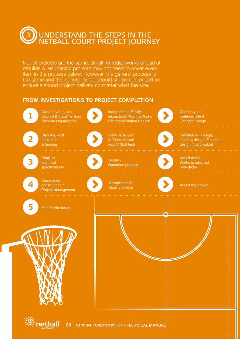
Not all projects are the same. Small remedial works or partial rebuilds & resurfacing projects may not need to cover every item in the process below. However, the general process is the same and this general guide should still be referenced to ensure a sound project delivery no matter what the size.
FROM INVESTIGATIONS TO PROJECT COMPLETION
Plan for the future
Acquit the projectCompliance & Quality checks
Commence construction / Project management
Award of the Works to selected provider(s)
Tender / Quotation process
Detailed technical specifications
Detailed civil design, Lighting design, Electrical design (if applicable)
‘Feature survey’ & ‘Geotechnical report’ (Soil test)
Budgets, cost estimates & funding
Confirm your preferred site & Concept Design
Independent ‘Facility inspection’, ‘Audit & Works Recommendation Report’
Contact your Local Council & State/Territory Member Organisation
1
2
3
4
5
TECHNICAL MANUALNATIONAL FACILITIES POLICY –20

4
CONTACT YOUR LOCAL COUNCIL & STATE OR TERRITORY MEMBER ORGANISATION
4.1 LOCAL COUNCIL
If you are part of a Club, Association or League then you should consult with your local Council about your project first. They are aware of the various funding opportunities and most funding bodies require you to have the support of your local Council in order to receive funding.
4.2 NETBALL MEMBER
ORGANISATIONCouncils, Clubs, Associations and Leagues should contact their State/Territory Member Organisation at the very start of the project journey.
Netball Australia does not have a facility advisory service but some State/Territory Member Organisations do. Either way, we strongly recommend that you liaise with your relevant State/Territory Member Organisation throughout the project (e.g. Netball Victoria if your facility is in Victoria). The relevant State/Territory Member Organisation may provide initial basic technical advice where possible to affiliated Clubs and Associations in their relevant state. The local State/Territory Member Organisation should be the first port of call for Clubs, Associations, Leagues and Councils – from project concept through to project completion.
Works recommendations and more detailed advice can be provided on a fee for service basis through independent service providers.
Services range from:
Site inspections
Facility condition & compliance audit reports
Project cost estimates
Concept designs
Preparation of technical specifications
Detailed design drawings
Management of the tendering processes
Full project management & project sign off including compliance checks.
Netball ACT Northbourne Ave, Dickson ACT 2602PO Box 423, Dickson ACT 2602T: 02 6241 4088E: [email protected]: act.netball.com.au
Netball New South Wales Netball Central, 2 Olympic Boulevard, Sydney Olympic Park NSW 2127PO Box 396, Lidcombe NSW 2141 T: 02 9951 5000 / Fax: 02 9951 5099E: [email protected]: nsw.netball.com.au
Netball NT235 Abala Rd, Marrara NT 0812PO Box 2391, Parap NT 0804T: 08 89451733E: [email protected]: nt.netball.com.au
Netball Queensland 208-210 Beaudesert Rd, Moorooka QLD 4105PO Box 50, Moorooka QLD 4105 T: 07 3848 6330E: [email protected]: qld.netball.com.au
Netball South Australia 155 Railway Terrace, Mile End, SA 5031PO Box 2082, Hilton Plaza SA 5033T: 08 8238 0500E: [email protected]: sa.netball.com.au
Netball TasmaniaBlundstone Arena15 Derwent Street Bellerive TAS 7018PO Box 405 Rosny TAS 7018Phone 03 6282 1824E: [email protected]: tas.netball.com.au
Netball Victoria487 King Street West Melbourne 3003PO Box 60, Nth Melbourne VIC 3051T: 03 9321 2222E: [email protected]: vic.netball.com.au
Netball WA State Netball Centre200 Selby Street. Jolimont WA 6014PO Box 930, Subiaco WA 6904 T: 08 9380 3700E: [email protected]: wa.netball.com.au
NATIONAL FACILITIES POLICY – 21TECHNICAL MANUAL

5
INDEPENDENT FACILITY INSPECTION, AUDIT & WORKS RECOMMENDATION REPORT
An independent assessment of your project is an important step in achieving a successful outcome. Examples of issues that a facility audit may determine include:
• The condition of the existing court base, pavement and court surface: Will crack repairs, resurface, re-sheeting or partial rebuild suffice, or is a total reconstruction required?
• The constraints, issues and design possibilities of your greenfield site or existing facility
• The possible reasons for pavement failures: Quite often insufficient pavement design and construction, poor drainage and/or tree root invasion are major contributors to pavement failure. These identified issues will need to be addressed and corrected to ensure a long term outcome once your redevelopment works are complete
• Is the facility compliant? All court dimensions, run-off zones and goal post heights are measured and compared to the current standards required for netball courts
• The condition of the supporting infrastructure: The goal posts and light towers assessed and notations made on their condition
• Shelters, seating, car parking, clubhouse, change room/toilets and accessibility provisions: It is important to identify where the facility can improve in regards to these amenities
• Recommendations for works required: To improve the playability and functionality of the netball court facility. Short term and longer term recommendations can be provided for planning & budgeting purposes.
NOTE: Take the time to invest in a facility audit. Identifying the issues and works required in a holistic way can reduce project risk and greatly improve project outcomes.
Asphalt cracking
Non-compliant court
TECHNICAL MANUALNATIONAL FACILITIES POLICY –22

6
SELECTING A SITE
6.1 SITE SELECTION OVERVIEW
On many occasions the available land set aside by Councils for recreational activities is leftover land that is not suitable for the construction of buildings and/or housing. A mandatory investigation of the soil and drainage conditions of the existing or proposed site is crucial. This will determine whether the land is suitable for the construction of new netball courts and what type of pavement construction is required.
Netball courts should be positioned in relation to the service they are to provide to the community. For example a football/netball Club court would most often be positioned near the football amenities and existing supporting infrastructure.
There are two major benefits to doing this:
Visibility between the football oval and clubrooms and the netball court are recommended to facilitate a cohesive relationship between the two sports
Financial benefit to the project; new toilet or change facilities, additional car parking or shelters can add many dollars to a project.
Larger Association court facilities are best placed where the number of courts can increase as demand increases. It should be accessible to the community it services and ideally provide space for increased pavement sizes to accommodate walkways between courts, marshalling/warm up areas, shelters and lighting. Many large netball facilities are well positioned near indoor sports stadiums to take advantage of the existing change/toilet facilities and car parking.
All netball facilities should be well supported with toilet/change room amenities, car parking and accessible path connections.
6.2 SITE PREFERENCE
Preference should be given to a site that provides the following:
• Adaptable to the surrounding area with good supporting infrastructure already in place
• Compactable soil - avoid highly reactive clays where possible
• No large trees within a reasonable distance (approx. 15-20m) from the proposed courts, or else root barriers or selected removal will be required (removal can be costly and require Council permits)
• No overhead electrical wires or major underground services infrastructure, such as; mains sewer, mains water, Fibre Optic Cable – build over permits may not be possible for certain underground assets
• Scope to construct the court and surrounding areas so that the court drains freely and does not allow water to enter or pond around the pavement area.
• Sufficient space to build full sized courts with correct clear runoff zones and space for walkways, shelters and marshalling/warm up areas
• Provide good machinery access and a reasonably level ground. Sites with large gradient/level changes can be built on but the construction costs can be much greater with extensive earthworks and retaining wall works required.
6.3 SITES TO AVOID
Sites should be avoided if they:
• Contain uncontrolled fill• Have a high water table or are prone to flooding• Have poor drainage• Have a poor soil rating• Have a history of having unsuitable fill material;
including buried waste, tree stumps• Cannot accommodate compliant courts and future
growth predictions• Cannot service the expected traffic flows, power supply
demand or car park and toilet requirements.
A thorough site inspection and site history can provide valuable information but a comprehensive geotechnical report will determine the most accurate recommendations to ensure a long lasting pavement. This will minimise premature base failures.
NOTE: On no account should the design or construction process commence without appropriate soil testing and reporting. The likelihood of premature pavement failure can increase greatly if this vital step is ignored. Fixing a failed court can end up costing more than the original construction cost. See Section 8 ‘Site Investigations’ in this manual.
NATIONAL FACILITIES POLICY – 23TECHNICAL MANUAL

6
SELECTING A SITE
6.4 CONCEPT DESIGN
Once the site is selected engaging an industry expert to develop a concept design plan is recommended. This will ensure that all future needs are met. This can clearly illustrate the proposed works and confirm that the project is viable on the proposed site. Potential stakeholder communications and funding applications can be greatly improved by including this type of information. It also minimises any confusion regarding the nature and scope of the proposed project. The concept
design should ensure current standards for court dimensions and minimum run-offs and accessible pedestrian access/walkways are accommodated. Where possible it should also depict spoon drains and tree root barriers. A concept design can be drawn over a scaled aerial photograph or for a more accurate plan a feature survey should be used. The courts should be orientated North/South wherever possible. See Section 8.4 and Section 9.4 in this manual.
Example of Concept Design Plan
TECHNICAL MANUALNATIONAL FACILITIES POLICY –24

7
BUDGET & FUNDING
7.1 BUDGET OVERVIEW
Obtain enough funding to build the courts right, first time!One of the biggest mistakes Clubs, Associations and Councils make is not estimating a large enough budget to build the court(s) properly. Important design components such as pavement type and construction standards, drainage and tree root barrier works quite often drop off a project or are altered simply because the Club/Council did not budget correctly in the planning and funding stage. The courts can fail quickly when this happens and subsequent rectification costs can balloon rapidly.
Poor drainage and tree root damage contribute to the vast majority of premature pavement failures.
NOTE: IT CAN COST MORE TO FIX A FAILED COURT THAN WHAT THE COURT COST TO BUILD IN THE FIRST PLACE!
If the budget doesn’t exist to build the court with the proper provisions then don’t build it – wait a little longer, get the right amount of money together and build it properly or alternatively, stage the project.
7.2 COST ESTIMATES
Obtain an independent cost estimate for the project early in the process to ensure accurate costings are considered in the search for funds. This should allow the construction of a quality, long-lasting netball court for each specific site.
Must have items to consider in your cost estimate & budget:
• Costs for Site investigations, Feature & Title Surveys and Soil Testing (Geotechnical) works
• Concept design works• Include a minimum 10% design and construction cost
contingency – see Contingency (Section 7.3) on the next page for more information
• Allow a nominal sum for feasibility study, permits and fees• Surrounding ground shaping and drainage works• Demolition of existing infrastructure (if required) and/or
preparation of the site• Court base construction including, subgrade,
crushed rock & pavement layers:
– MUST ensure sufficient budget to allow a sound pavement to be constructed for your sites soil type or else the court will fail
– MUST allow a large enough pavement to accommodate compliant court dimensions & run-off zones – (see Section 2 ‘Compliance’ of this manual)
• Tree root barriers to all external pavement boundaries to help protect the pavement from tree root invasion and moisture changes caused by existing trees and any future tree plantings
• Concrete plinths and spoon drains to support the entire pavement perimeter (especially for asphalt pavements). Install agi drains and a number of large drainage pits to carry storm and ground water well away from the pavement area
• Independent project management to ensure the project is designed and delivered according to the site investigations, design and specifications.
NATIONAL FACILITIES POLICY – 25TECHNICAL MANUAL

7
BUDGET & FUNDING
7.2 COST ESTIMATES Continued
Items to also include, if relevant to the project:
• Circulation space for pedestrian access and shelter/seating areas between courts (in addition to the minimum run-off areas) for larger multiple court facilities – 1.5m wide additional space is preferred where possible. See Section 9.10 ‘Inclusivity, Accessibility & Signage’ in this manual.
• Accessible pedestrian connections to the court from the car park and change/clubroom facilities
• Acrylic surface – Ensure the entire court and run-off areas have a consistent surface in order to be compliant. Preference is to surface to the outside edge of pavement or in a straight line to the face of any fencing
• Fencing – Low level is more welcoming and preferred if court security is not an issue
• Court and pedestrian/access lighting• Supporting utilities including power supply to the site
(Power supply upgrades can be very costly if they are required)
• Marshalling/Warm up pavement area(s) with a number of goal posts (ideal at large multiple court facilities)
• Change room / clubhouse / toilet facilities (dependent upon venue size and usage)
• Car park facilities (size dependent upon the number of courts and predicted usage)
• Construction of supporting infrastructure including seating, shelter, drinking fountain(s)
• Accessible storage room/shed for maintenance, game day and training equipment
• Landscaping to improve aesthetics and provide a welcoming environment. This will also reduce court maintenance issues such as loose stones, dirt and dust on the court surface
• Any site-specific issues that may result in potential liability insurance issues should be allowed for.
IMPORTANT: If the need for an asphalt or concrete base is not yet known, a geotechnical (soil test) report at this stage will be needed. This will determine the sites suitability for an asphalt or concrete pavement and therefore the predicted costs. Alternatively, budgeting for a worst-case scenario (concrete base) is recommended.
7.3 CONTINGENCY
Whether on a tight budget or not, a contingency allowance should always be set aside in addition to the quotation price accepted. This will provide a buffer for the unexpected or accidentally forgotten items or unforseen subgrade issues that can crop up throughout construction projects. A safe allowance is normally around 10% of the accepted contract price, however, lesser amounts can be used where there is minimal “in-ground” works required or the specification documents produced are considered to be of a high quality standard. If the geotechnical report indicates a poor soil type or excessive ground moisture then a larger contingency may be required as the likelihood of identifying soft spots/unstable ground during the sub-grade construction stage may increase.
7.4 FUNDING
There are numerous funding opportunities available. However, funding for netball court projects is highly sought-after in a highly competitive grants market. Clubs, Associations and Leagues are advised to follow the advice in this Technical Manual and do their homework. Many funding bodies require Council support for the project and quite often require the Club, Association or League to submit the application through their local Council (auspice).
Your relevant State/Territory Member Organisation may also be able to point you in the right direction and offer support and assistance where possible, see Section 4 ‘Contact your local Council & State/Territory Member Organisation’ in this Manual.
TECHNICAL MANUALNATIONAL FACILITIES POLICY –26

8
SITE INVESTIGATIONS
Thorough site investigations are critical to every redevelopment project; whether it be reconstructing an existing court or starting from scratch on a greenfield site. Sound investigations may save you many thousands of dollars or even a life! Before any detailed design works can proceed, the following are essential:• Geotechnical report/Soil report• Title survey• Service detections• Feature survey.
8.1 GEOTECHNICAL
REPORT/SOIL REPORT
No major construction works should ever be planned without a site specific soil report from a geotechnical engineer.Before the design and construction stages commence there is the need to ascertain the sites soil type. It is essential that a Geotechnical Engineer conducts soil tests of the project site and provides a report with sports pavement recommendations. Light tower footing recommendations should also be provided, if applicable.
This specialist consultant will undertake site investigations by means of drilling bore holes and taking soil samples in and around the proposed court site to ascertain the existing soil type and condition. The results of these samples and tests are then used to determine the structural requirements of the netball court; excavation depth, sub-grade treatment, sub-base and base detail for construction (depth of excavation, crushed rock layer depths and pavement type and thickness).
NOTE: Light tower construction requires a deeper soil test (approx. 3m depth) than a pavement only construction (approx. 2m depth), so it is important to let the civil engineer and/or geotechnical company know if you intend to install light towers.
The civil engineer will determine how the subgrade should be prepared and design a pavement structure based on their site inspection and review of the geotechnical report. One, two or even three layers of Fine Crushed Rock (granular material) may be required at the sub-base stage in the court construction. The number of layers and their depths will be dependent on the soil type and the type of base (asphalt or concrete) proposed. There is no ‘one pavement design fits all’.
NOTE: Each site will be different, therefore, don’t ever presume that the depth of the sub-base material and type of base used at a neighbouring town’s netball club will be ok for your netball court project.
The results of the soil tests are classified based on the expected movement of the soil; this is generally related to the capacity of the soil to shrink and swell.
The typical classifications are:
CLASS ‘A’ – Little or no ground movement
CLASS ‘S’ – Slightly reactive site
CLASS ‘M’ – Moderately reactive site
CLASS ‘H’ – Highly reactive site
CLASS ‘E’ – Extremely reactive site
CLASS ‘P’ – Problem site.
The geotechnical report should also advise the following:
• The depth of the top soil
• If there is any fill and if so whether it is likely to compact adequately
• If there are any signs of decomposing vegetation and/or rubbish within the subgrade.
• If the soil profile is excessively moist and/or over a perched water table
• The depth to which a solid and firm sub-grade is likely to be found.
Soil types and ground conditions can vary greatly from site to site; sometimes it can even vary within the one site. Therefore, it is critical that soil testing is carried out on every netball construction project.
NOTE: NEVER assume that you know what the soil type/condition/classification is for a particular site.
8.2 TITLE SURVEY
A Title Survey should be undertaken to determine the actual title boundaries in which the courts can be built. Title boundaries can have a major impact on designs and it is important to note that many physical boundaries (fences) are not accurate. Title boundaries within a reserve can also impact power supply requirements.
NOTE: Never assume that fence or visible boundary markers are accurate. It can be very costly to find out that the courts have been built over someone else’s land after the fact.
NATIONAL FACILITIES POLICY – 27TECHNICAL MANUAL

8
SITE INVESTIGATIONS
8.3 SERVICE DETECTIONS
Service Detections should be undertaken to determine what underground services are present. This is required before any geotechnical drilling can take place and will also identify what services may be affected by the court build. Some underground service providers do not allow their assets to be built over. A query to ‘dial before you dig’ (DBYD) is an absolute must (telephone 1100 or query online at www.1100.com.au), but never assume that this will tell you everything. Some services are not known to DBYD and many private or reserve land parcels are not included in the DBYD documents. You should always engage a professional service detection company to scan the site and mark out all underground services. An accurate plan with the services plotted should be provided as markers can wear or wash away quickly in heavy rain. Services should be taken very seriously as some (such as power) can have life threatening consequences if they are accidentally hit during soil test drilling or construction. The locating of underground services may also save many thousands of dollars. Never assume that there are no underground services at a greenfield (clear) site. Often there are no visible markers to alert prospective designers or court builders.
8.4 FEATURE SURVEY
A feature survey should be undertaken to produce a topographical/feature survey of the site. Feature surveys are used as a base for the concept and detailed design stages. This allows the designers to plot the courts/pavement areas and the supporting infrastructure (eg shelters & light towers) accurately.
A feature survey shows the following:
• Existing levels over the site
• Existing path of overland water flow so that this can be considered and incorporated into the civil and drainage design
• The extent of earthworks that will be required to create a platform for the netball court construction
• The exact location of any existing features on the site – such as trees, fences, buildings, concrete pathways, power supply lines and water meters. It is important to know if any existing features will impact the proposed construction works (the courts may need to be designed around certain features or some features may need to be removed, demolished or relocated)
• The existing services as identified and marked during the service detections works (as noted above)
• The title boundaries as identified and marked during the title survey works.
TECHNICAL MANUALNATIONAL FACILITIES POLICY –28

9
DESIGN
To achieve a desirable long-term outcome, a sound design process should be followed.
Design
NATIONAL FACILITIES POLICY – 29TECHNICAL MANUAL

9
DESIGN
9.1 DESIGN OVERVIEW
To achieve a desirable long-term outcome, a sound design process should be followed. The following design considerations for a netball court facility are recommended:• Determine the needs of your facility – Consulting with
the Club and/or community to determine future usage requirements is recommended; How many courts are required? How will the facility interact with the surrounding infrastructure? Identify any gaps where additional infrastructure is required (i.e.: paths, car parking, change rooms, shelters, seating).
• Ensure appropriate investigations are undertaken such as soil testing, feature survey, title survey & engineering advice – These coupled with the concept design plan will assist in determining the appropriate base for the courts (i.e.: asphalt/concrete), appropriate subgrade treatment, crushed rock layer numbers and overall depth, positioning, and overall success of the project. See Section 8 ‘Site Investigations’ in this manual.
• Engage an industry expert to develop a concept design plan to ensure all future needs are met. Ensure current standards for court dimensions and minimum run-offs and accessible pedestrian access/walkways are accommodated. The courts should be orientated North/South wherever possible (see Section 9.4 ‘Court Orientation’ in this manual).
• Liaise with your State/Territory Member Organisation (i.e. Netball Victoria in Victoria) from the project scoping stage through to the construction stages and project completion. See Section 4 ‘Contact your Local Council & State or Territory Member Organisation’ in this manual.
• Ensure the courts are compliant – Netball courts must be 30.5m long x 15.25m wide and have a minimum 3.05m run-off clear zone to the outside of each sideline and baseline and have a minimum 3.65m between courts. They must be of the same surface and level as the court. This is an International Netball Federation rule introduced to ensure the safety of players and umpires. See Section 2 ‘Compliance’ in this manual.
• Ensure court works are designed specifically for each site to ensure all facets of the facility upgrade are considered. Soil type, existing drainage issues, water catchments and previous pavement failures in and around the site should be considered in any design work. Ensure the pavement is designed to allow compliance to the current standards for court dimensions and run-offs for netball. See Section 2 ‘Compliance’ in this manual.
• An independent design and specification package should be prepared wherever possible – An independent engineer will utilise industry best design principles and consider the soil & site conditions when designing the court. If a design and construct method is considered, research is important. There are some very reputable design and construct companies in the industry that can offer a great result but this can be an area where you get what you pay for, so don’t base your decision on cost alone.
• Ensure the court/pavement has adequate fall (1:100) – Either in both directions or diagonally across the courts on a single constant plain. This should fall to a formed drainage system by way of concrete spoon drains to allow storm water to outfall efficiently and away from the pavement area. In multiple outdoor court facilities, spoon drains should be provided between every second court, as a minimum, to prevent unplayable conditions on the lower courts. Ensure all drainage infrastructure (including spoon drains and pits) is outside of the required minimum run-off zones See Section 2 ‘Compliance’. Where fencing is installed, perimeter drainage infrastructure should be positioned outside the line of fencing wherever possible.
• Ensure the courts perimeter drainage is also designed to allow stormwater to drain efficiently away from the pavement areas. Spoon drains should be installed at the base of retaining walls and earthen swales should be provided around the court pavement to minimise water ingress onto and under the pavement from the surrounding areas. Perimeter agi-drains should be installed to protect the pavements subgrade and sub-base from moisture variations to avoid major pavement damage (such as cracking and collapsing).
• Tree root barriers should be installed to all boundaries where existing and future plantings may occur within 10-15m of the pavement. This will minimise tree root damage in the future. Avoid planting near courts as moisture variations and tree root invasion in the subgrade around and under the pavement can cause significant damage to the pavement.
• The courts surface should not hold water. The surface tolerance is +/- 3mm maximum deviation when measured in any direction under a 3 metre straight edge. There should be no obvious water ponding areas across the pavement. Low areas hold water and collect silt, making the court slippery underfoot and creating ongoing maintenance issues. Ponding areas are also unpredictable underfoot and prevent the foot from contacting firmly with the court surface when in play. This can result in an unplayable court in wet conditions – this should be avoided at all costs as netball is often played in wet conditions.
TECHNICAL MANUALNATIONAL FACILITIES POLICY –30
9
DESIGN
9.1 DESIGN OVERVIEW Continued
• Ensure goal posts are specified correctly as per Section 9.6 ‘Goal Posts’ in this manual; they need to be 3050mm high and fitted with full length high density foam padding.
• Provide clear direction regarding line marking – Ensure all dimensions and run-offs are compliant with the current Standards for Club competition (see Section 2 ‘Compliance’ in this manual). All lines must be 50mm wide with clean sharp edges and be a textured water based acrylic (see Section 9.5 ‘Line marking’ in this manual).
• Address accessibility throughout the site to ensure compliance with the Disability Discrimination Act (DDA). Netball facilities should be inclusive and accessible to all members of the community. Path connections and/or ramps should be provided between the court(s) and the car park, changeroom, toilet and clubroom facilities (A brief guide to the Disability Discrimination Act is available online at www.humanrights.gov.au/our-work/disability-rights/guides/brief-guide-disability-discrimination-act ).
• Consider installing seating and shelters to the sideline boundaries of the court to accommodate and support the players, coaches, scorers and spectators. These must be outside the required run-off zones (including shelter veranda/overhangs).
• Install a drinking fountain in close proximity to the court facility (if possible).
• Fencing is not essential for netball, but if included it should comply with the current standards AS1725-2010 Part 1, 2 or 5 (depending on height). Fencing should allow access gates for emergency/maintenance access and sufficient pedestrian access gates for practical reasons. Preference is for 1.2m high black powder coated chainmesh fencing with top and bottom rails to improve game day functionality whilst maintaining a welcoming feel. If security is an issue 3m high fencing would suffice (see Section 9.8 ‘Fencing’ in this manual).
• Lighting should adhere to the current standards for sports lighting standard AS2560.2.4 and Netball Australia’s indoor lighting recommendations outlined in Section 9.7 ‘Lighting’ section of this manual. Ensure the lighting infrastructure is designed and installed outside the required clear run-off zones. The design, layout and illuminance (lux) ratings should be suitable for the type of facility and level of play expected. Lighting should also be non-obtrusive to nearby residences and meet future growth/needs. (see Section 9.7 ‘Lighting’ in this manual)
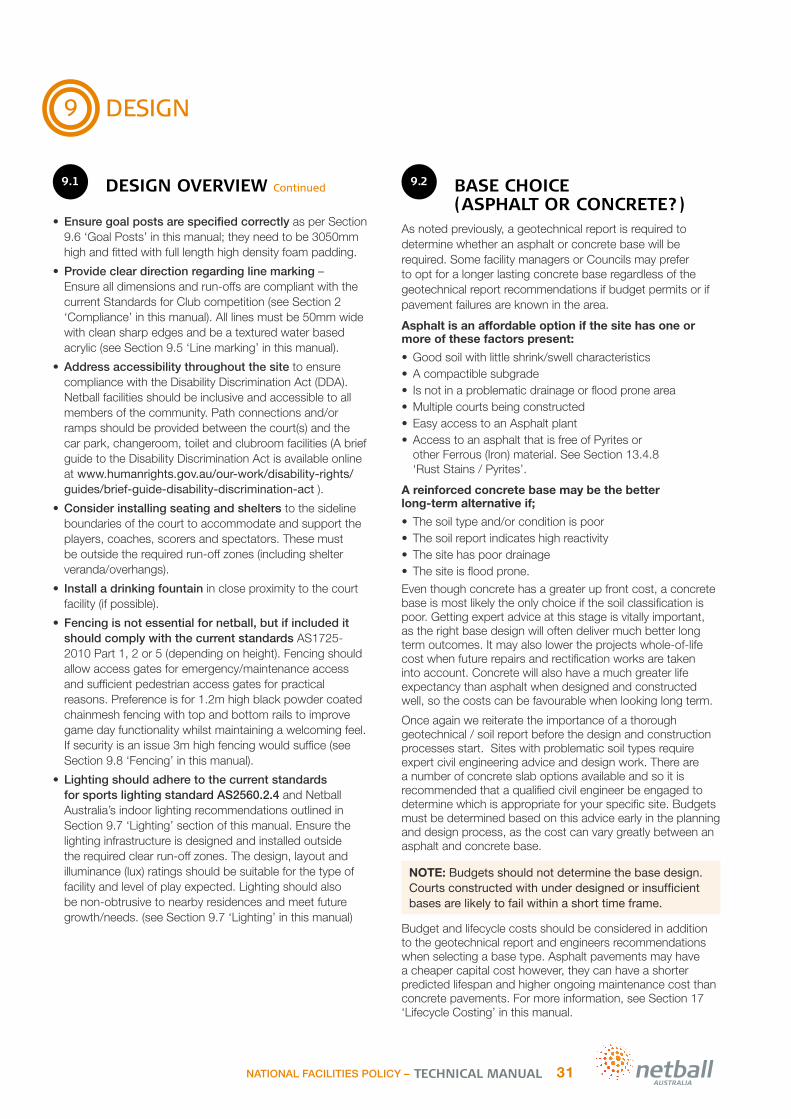
9.2 BASE CHOICE
(ASPHALT OR CONCRETE?)As noted previously, a geotechnical report is required to determine whether an asphalt or concrete base will be required. Some facility managers or Councils may prefer to opt for a longer lasting concrete base regardless of the geotechnical report recommendations if budget permits or if pavement failures are known in the area.
Asphalt is an affordable option if the site has one or more of these factors present:
• Good soil with little shrink/swell characteristics• A compactible subgrade• Is not in a problematic drainage or flood prone area• Multiple courts being constructed• Easy access to an Asphalt plant• Access to an asphalt that is free of Pyrites or
other Ferrous (Iron) material. See Section 13.4.8 ‘Rust Stains / Pyrites’.
A reinforced concrete base may be the better long-term alternative if;
• The soil type and/or condition is poor• The soil report indicates high reactivity• The site has poor drainage • The site is flood prone.
Even though concrete has a greater up front cost, a concrete base is most likely the only choice if the soil classification is poor. Getting expert advice at this stage is vitally important, as the right base design will often deliver much better long term outcomes. It may also lower the projects whole-of-life cost when future repairs and rectification works are taken into account. Concrete will also have a much greater life expectancy than asphalt when designed and constructed well, so the costs can be favourable when looking long term.
Once again we reiterate the importance of a thorough geotechnical / soil report before the design and construction processes start. Sites with problematic soil types require expert civil engineering advice and design work. There are a number of concrete slab options available and so it is recommended that a qualified civil engineer be engaged to determine which is appropriate for your specific site. Budgets must be determined based on this advice early in the planning and design process, as the cost can vary greatly between an asphalt and concrete base.
NOTE: Budgets should not determine the base design. Courts constructed with under‐designed or insufficient bases are likely to fail within a short time frame.
Budget and lifecycle costs should be considered in addition to the geotechnical report and engineers recommendations when selecting a base type. Asphalt pavements may have a cheaper capital cost however, they can have a shorter predicted lifespan and higher ongoing maintenance cost than concrete pavements. For more information, see Section 17 ‘Lifecycle Costing’ in this manual.
NATIONAL FACILITIES POLICY – 31TECHNICAL MANUAL

9
DESIGN
9.3 COURT LAYOUT
It is recommended that netball courts are designed in relation to the service that they provide to the individual site and user group. For example:If the court is part of a football reserve and it services a football/netball level competition, it may be beneficial if the court:
• Was positioned as close to the football ground and clubhouse/pavilion amenities as possible
• Was positioned as close to the car park facilities as possible with firm & stable path connections to assist access
• Provided sightlines between the football ground and the netball court to encourage a cohesive connection to the football community. This encourages spectator/player cross overs between the two sports
• Provided scorers’, coaches’ and spectator shelters positioned on the court sides (outside the required clear run-off zone).
If the courts are part of a multiple court Association facility it may be beneficial to have:
• Adequate change room/toilet facilities in close proximity.
• Access to potable water
• Adequate shade provision
• Adequate seating, dependant on level of competition and expected spectator numbers
• Adequate scorers and coaches shelters (to the sidelines - outside of the required clear run-off zones)
• Adequate spectator shelter and viewing areas (outside of the required clear run-off zones)
• Sufficient pedestrian/spectator access walkways (outside of the required clear run-off zones). These should be positioned between and to the ends of courts in high pedestrian movement corridors (an additional 1.5m is preferred in addition to the required run-off zones if considered). See diagram in Section 2.3 ‘Compliance - Court Dimensions & Run-Offs In Detail.’
• Warm up/marshalling area with a firm pavement
• Accessible path connections between the courts and the courts supporting infrastructure, such as car parks and clubrooms/changeroms.
NOTE: These are recommendations only (not a standard) provided for club/association/council consideration. Stakeholders can benefit from consulting with the user groups. This will assist in determining the most suitable layout and supporting infrastructure required for the particular venue and use.
9.4 COURT ORIENTATION
A North-South court orientation is preferred to minimise the effects of the suns glare.The time of day for play (early morning or late afternoon) as well as the time of year the sport is played (winter or summer) may have a bearing on optimal orientation. The aim, however, is to determine the advantages and/or disadvantages of the sun’s direction and other natural factors. It is generally recommended that playing areas are orientated in a north-south direction to minimise the effect of a setting sun on players. The best common orientation is 15° east of north.
You can alter this by various degrees to increase player comfort or site constraints. There is an allowable limit within the current standards, netball allows between 20° west of north and 35° east of north. This is outlined on Page 6 of the ‘Sports Dimensions Guide for Playing Areas July 2008’ produced by the Department of Sport and Recreation Western Australia.
It should, however, be noted that there are some existing netball courts with an East/West orientation. Although this is not ideal, it may be required where a North/South orientation within the noted tolerance is not possible due to site constraints.
360º
reciprocal bearingsshown dotted
E
n
S
W
15º
best commonorientation
35º
75º
90º
125º
135º
160º180º195º
215º
255º
270º
305º
315º
340º
limits of good orientation wherea uniform direction of play forall facilities can be arranged
association & rugby football
hard court tennisbasketballnetball
grass court tennis
cricke
t, softballbase
ball
TECHNICAL MANUALNATIONAL FACILITIES POLICY –32

9
DESIGN
9.5 LINE MARKING
All netball line marking should have the following:
• 50mm wide lines• Textured water based acrylic paint suitable for wet
weather netball use (in no circumstance should oil based road or traffic paint be used)
• Line marking paints that are approved for application on asphalt sports pavements
• A finish that is the same texture and level as the surrounding court surface so that it is stable underfoot
• Straight lines with clean, crisp edges – taping the lines will produce sharp lines and is recommended
It is also important that:
• New asphalt needs to cure for a minimum of 14 days before line marking can commence
• The paint is applied in thin layers to a clean & dry surface – heavy coats will result in cracking and curling along the edges.
NOTE: The method of line marking will vary between each applicator. One approach uses a string line and masking tape machine, while the other uses a special gravity fed line-marking machine. The masking tape method will enable two coats to be applied, this can offer superior durability. Both methods should produce a sharp defined line with no fogging at the edges.
When using the masking tape approach, it is recommended that the non-slip textured water based line-marking paint is applied with a paintbrush or a 50mm wide roller. Care should be taken to ensure the paint does not ‘bleed’ under the tape (which results in messy and unsightly lines). Line-marking airless spray units and aerosol cans are not recommended. The use of these methods results in overspray and rough edges, leaving a poor quality finish.
The masking tape method
Spray unit used resulting in unsightly overspray
Line marking allowed to ‘Bleed’ under the tape
Well installed line marking – crisp & sharp edges
Asphalt damage due to oil based paint used
The gravity fed line marking machine method
360º
reciprocal bearingsshown dotted
E
n
S
W
15º
best commonorientation
35º
75º
90º
125º
135º
160º180º195º
215º
255º
270º
305º
315º
340º
limits of good orientation wherea uniform direction of play forall facilities can be arranged
association & rugby football
hard court tennisbasketballnetball
grass court tennis
cricke
t, softballbase
ball
NATIONAL FACILITIES POLICY – 33TECHNICAL MANUAL

9
DESIGN
9.5 LINE MARKING Continued
ColourThe choice of line-marking colour is important but it is usually determined by the user group(s). There are no international standard colour schemes for netball court markings. Most sports require white lines for major competitions and the Official Rules of Netball state that white is preferred. Where netball courts are the only sport marked on the pavement, white is usually adopted. In multi-sport court facilities there are some varied industry practices available to help determine which sport has which line marking colour, such as:
• The most frequently used sports are usually marked out in White, followed by Yellow, Blue & Red
• The faster the ball game the lighter the line marking colour i.e.: the lightest colour represents the fastest sport to the darkest represents the slowest. In a situation where tennis, basketball, netball and volleyball are played on the same court, tennis would be rated as the fastest sport and therefore white would be used for the line marking. Basketball is the next fastest and therefore yellow would be used. Netball is classified slower than basketball so red is used for the line marking and so on.
This is outlined on Page 8 of the ‘Sports Dimensions Guide for Playing Areas July 2008 produced by the Department of Sport and Recreation Western Australia.
Note: These are industry practices only - not a standard.
9.6 GOAL POSTS AND PADDING
In addition to the goal post specification in Section 2 ‘Compliance’ of this manual, the following items should be considered:
Goal Posts• The contractor must ensure the exact 3050mm goal post
height from the courts finished surface level to the top of the goal ring is achieved
• Painted white preferred
• Must be fitted with full length padding for training and match play. See the following Goal Post Padding references.
• The top of the goal post should be steel capped and must not project above the height of the goal ring
• The goal ring is to be especially strong in public outdoor settings where rough play can be experienced and vandalism is prevalent. The ring may need additional support in these circumstances, if so this should be
conveyed to the goal post supplier. The ring shall be arc welded to the goal post and preferably have small steel loops to which the chain or cotton mesh net attaches. All outdoor court goal nets should be strong all weather nets
• The goal posts should be hot dipped galvanised steel as they have a longer lifespan than ordinary galvanised steel. This will help resist rusting at ground level
• The goal posts can be installed directly into a concrete footing or installed into a ground socket. If they are to be inserted into a ground socket, they should have a reasonably tight fit inside the sleeve so that it does not wobble or allow the post to turn. A locking pin welded on to the goal post that slots into a small hole near the socket will stop the goal post moving around and stabiliser bars or rods can be used to help ‘lock’ the posts into a fixed and stable position
• The goal post concrete foundation (footing) dimensions and installation and/or ground socket installation should be determined by the manufacturer’s recommendation for their product. In lieu of this, the court builder or engineer will be able to determine a suitable footing design based on the sites ground conditions. At a minimum the concrete goal post footing should be a minimum of 460mm x 460mm x 610mm deep. Note: The concrete footing should be poured using job mixed concrete i.e.: crushed rock, sand and cement or plant mixed concrete. Do not use rapid set concrete as this has a tendency to rise out of the ground with the sleeve and/or post
• The goal post should be installed so that the internal face of the post is positioned on the internal face of the baseline so as not to encroach on the Playing Area of the court inside the baseline -any excess post width and/or post support base or socket is to impede on the run-off area outside of the court instead
• Ensure that water does not pond at the post/footing connection, this is especially important in salt-water environments
• If there is any doubt about the safety or stability of a goal post installation, consult a structural engineer.
NOTE: The type of goal post specified in this Technical Manual is readily available across Australia and does accommodate both the 3.05m & 2.4m goal post height adjustments.
This manual has intentionally nominated a 60mm minimum goal post diameter, as the previously specified 65mm minimum is not readily sourced in Australia.
TECHNICAL MANUALNATIONAL FACILITIES POLICY –34

9
DESIGN
9.6 GOAL POSTS AND PADDING
Continued
PaddingGoal Posts must be fitted with padding for the entire length of the post (3m) for competition play. NetSetGO court goal posts can be fitted with reduced height padding of 2.4m due to the adjustable goal ring height, low level of play and expected height of the participants in this playing group.
The length of padding specified in this Technical Manual is readily available across Australia.
All padding must have no more than a 50mm maximum thickness. It should also have the following characteristics as a minimum:
• Premium quality high density foam core for maximum protection and safety
• Heavy Duty PVC outer lining for outdoor use
• Start at the base of the goalpost and extend up the goalpost to the standard height required
• Full length Velcro fastening for maximum stability
• Velcro fastening to be installed so that is at the back of the goal post at the mid-point at all times to ensure maximum protection to the face of the post for players on court.
9.7 LIGHTING
9.7.1 LIGHTING STANDARDS
There are certain lighting standards and recommendations for training and competition netball for both outdoor and indoor netball facilities. These should be considered and adhered to when planning and designing netball lighting projects.Netball has seen a growth in both the number of courts that have been lit for competition and training purposes and an increase in the quality of the lighting installed. This is largely due to improvements in the technology, a better understanding of the standards for sports lighting and more cost effective lighting solutions now available for the sport.
Lighting systems have also come under increased scrutiny due to a requirement that court lighting should not intrude into the lifestyles of people away from the court. This includes neighbours and vehicular traffic.
Recommendations are provided within this Technical Manual based on a review of lighting standards for indoor and outdoor netball. Sports lighting standards have been introduced to ensure good visual conditions for players, athletes, referees, spectators and colour television (CTV) broadcast where applicable.
The Australian Standard for Outdoor Netball current at the time of preparation of this Technical Manual is AS 2560.2.4-1986 “Guide to Sports Lighting – Part 2.4: Lighting for outdoor netball and basketball.” It is understood this standard is also adopted by Netball New Zealand.
There is no specific Australian Standard that offers specific guidance on the Lighting for Indoor Netball. Instead the requirements to date have been covered under a general standard AS 2560.2.2-1986 “Guide to Sports Lighting – Part 2.2-Lighting of Multipurpose Indoor Sports Centres.”
NOTE: While Illuminance (Lux) and Uniformity tend to be the main lighting technical criteria stipulated for designs, other criteria both quantitative and qualitative are also important, such as: Control of glare; Control of Obtrusive (spill) light; Colour rendering; Backgrounds; Lighting systems & equipment.
NOTE: The European Standard EN 12193:2007 “Light and Lighting – Sports Lighting” has published lighting criteria which deal with sports lighting to ensure good visual conditions for players, athletes, referees, spectators and Colour Television (CTV) transmission.
There are no Australian Standard recommendations for colour television (CTV) broadcast. The establishment of suitable lighting criteria requires special consideration. This involves consideration of changes in broadcast technology.
NOTE: Lighting for television broadcast involves a range of further considerations and require expert lighting engineering guidance.
NATIONAL FACILITIES POLICY – 35TECHNICAL MANUAL

9
DESIGN
9.7.1 LIGHTING STANDARDS Continued
Netball lighting guidelines recommendationsNetball Australia conducted a review of the available Australian Standards in regards to outdoor and indoor Netball specific lighting.
The following interim recommendations have been adopted by Netball Australia pending review with Standards Australia as to whether AS 2560.2.2 and AS 2560.2.4 are destined for further revision / reissue.
NOTE: Australian & New Zealand Standards relevant to Netball have not been updated for nearly 30 years.
Netball lighting play level classificationsLighting specifications now align with the Class 1, 2 and 3 specifications listed in the European Standard EN 12193:2007 as follows:
Lighting Class 1 – International and National play shall meet this Classification:• Class 1 is set for top level competition• Venues will be designed to accommodate international
and national competitions which generally involve large spectator capacities with long potential viewing distances.
• Top Level Training can also be included in this class.
Lighting Class 2 – Regional Level Competition or Local Club Competition play shall meet this Classification.• Class 2 is set for mid-level competition such as
regional and local Club competition which generally involves medium size spectator capacities with medium viewing distances.
• High level training can also be included in this case.• The Level of play “Competition with large spectator
galleries” in AS 2560.2.4-1986 is expected to fall into this category
Lighting Class 3 – Low Level Competition play shall meet this Classification.• Class 3 is set for local or small Club competitions which
do not generally involve spectators.• General training, physical education (school sports) and
recreational activities will also come into this category.• The Level of play “Recreation or training and competition
with few spectators” in AS 2560.2.4-1986 is expected to fall into this category.
Note: Class 1 has been introduced as an additional class to cover Non-Televised Top Level Competition such as International and National.
Netball lighting recommendations – Outdoor netball (Non-televised)The lighting criteria for Outdoor Netball lighting (Non-televised) has been adopted per the European Standard but adapted to ensure levels all comply with the minimum values specified and widely used throughout Australia in current Australian Standard AS 2560.2.4.
TECHNICAL MANUALNATIONAL FACILITIES POLICY –36

9
DESIGN
9.7.1 LIGHTING STANDARDS Continued
Table R1: Outdoor Netball (Non-televised)
Lighting Class
Horizontal Illuminance Maintained Average Lux 1
Uniformity U1 (Min to Average)
Glare RatingMax 2
Colour RenderingRa8
Class 1Top-Level Competition
500 0.7 50 65
Class 2Mid-Level Competition
200 0.66 50 65
Class 3Low LevelCompetition/Training
100 0.5 50 65
1 All illuminance measurements apply at the court surface level. Illuminance Values pertain to the Principal Playing Area (PPA) being a court 30.5m x 15.25m. Illuminance values 75% of these are recommended in the Total Playing Area (TPA) being a court with safety run-offs defined as an area 37.5m x 22.5m and using the measurement grid of points setout in EN 12193 being 13 x 7 for PPA and 15 x 9 for TPA.
2 Glare Rating Observer Positions at which maximum GR rating apply are taken as PPA positions 1.5m above court surface at the 4 corners of the court and at each of the 3 points along the one-third of court lines being each sideline and the centre position along these lines. Total observer positions = 10 No.
NOTES:
Class 1 relates to International and National competitions, this level of competition is rarely (if at all) played on outdoor courts
These outdoor netball lighting recommendations have now included a specification for the Glare Rating (GR) Parameter.
GR = 50 maximum for all Classes of play has been adopted for all non-televised outdoor Netball venues.
Glare Ratings must be less for Televised sport with GR < 40 toward cameras a common requirement and reinforces the need to be cognisant of any CTV broadcast requirements at project inception.
Further detail on the calculations of glare rating can be found in CIE112-1994 ‘Glare Evaluation System for use within Outdoor Sports and Area Lighting’.
NATIONAL FACILITIES POLICY – 37TECHNICAL MANUAL

9
DESIGN
9.7.1 LIGHTING STANDARDS Continued
Netball lighting recommendations – Indoor netball (Non-televised)Lighting criteria for Indoor Netball lighting (Non-televised) has been adopted per the European Standard but adjusted with regard to the minimum values specified in current AS 2560.2.2 dealing with Multi-purpose Halls. This considers the likely reality that Indoor Netball Courts will generally need to anticipate multi-purpose sports use to maximise the utility of a venue.
Table R2 – Indoor Netball (Non-televised)
Lighting Class
Horizontal Illuminance Maintained Average Lux 1
Uniformity U1 (Min to Average)
Colour RenderingRa8
Class 1 750 0.7 65 Class 2 500 0.7 65 Class 3 3002 0.5 65
1 All illuminance measurements apply at the court surface level. Illuminance Values pertain to the Principal Playing Area (PPA) being a court 30.5m x 15.3m. Illuminance values 75% of these are recommended in the Total Playing Area (TPA) being a court with safety run-offs defined as an area 37.5m x 22.5m and using the measurement grid of points setout in EN 12193 being 13 x 7 for PPA and 15 x9 for TPA.
2 AS 2560.2.2 is a multipurpose standard and recommends 300 Lux at 1m above court surface. While EN12193:2007 permits a lesser illuminance of 200 Lux specified at the court surface and is a Netball sport specific recommendation. It is accepted that a 200 Lux recommendation at court surface, while suitable for Netball only, would not meet the minimum level recommended in AS 2560.2.2 of 300 Lux 1 m above court for multi-purpose sports. Given the likely reality that Indoor Netball Courts will generally need to anticipate multi-purpose sports use to maximise the utility of a venue, the minimum Illuminance Maintained Average for Lighting Class III has been intentionally set to also ensure compliance with AS 2560.2.2 Multi-Purpose sports minimum lighting recommendations for training.
Netball lighting recommendations – Colour television (CTV) lightingNetball lighting recommendations for colour television lighting include:
• Venues for which Colour Television broadcast requirements may exist require consideration of higher lighting levels and other more stringent lighting criteria than are listed in Tables R1 and R2
• Venues for which Colour Television broadcast requirements may exist require specialist lighting advice at the inception phase of a project to consider and reflect the changes in the technologies associated with CTV broadcast
• Recommendations for Colour Television Broadcast requirements may be found in the current publications CIE Technical Reports 83 and 169 and these should be considered in formulating the Sports Lighting CTV specification
• Reference is recommended to Lighting Criteria given in the “Free TV Australia Operational Practice OP-31 Lighting Requirements for Television” and the documents referenced by it. This is with a view to meeting future television standards as they evolve
• Free TV Australia has published a range of outdoor public broadcast requirements dealing with specific sports. Reference shall be made to any specific future publication dealing specifically with Netball and/or Basketball when setting the CTV lighting criteria
• Reference is also recommended to European Standard EN 12193 :2007 which also contains CTV broadcast lighting criteria for companion reference in formulating the Sports Lighting CTV specification
• The International Netball Federation (INF) lighting specifications of 1500 Lux (TV) for “Indoor Netball Facility Requirements” is a single criteria only. It is not recommended to be used in isolation of specialist advice and development of a comprehensive set of Lighting Criteria that adequately address the CTV broadcast requirements and with regard to the specific venue.
There are a number of other lighting parameters other than the obvious Horizontal Illuminance on the Court surface that are important to consider and specify for venue sports lighting suitable for CTV. These include, but are not limited to:
• Vertical illuminances• Uniformity• Glare rating towards cameras• Colour temperature• Colour rendering• 50/60 cycle flick• Qualitative requirements.
TECHNICAL MANUALNATIONAL FACILITIES POLICY –38

9
DESIGN
9.7.1 LIGHTING STANDARDS Continued
NOTE:
There is a need to consider CTV Lighting requirements at the outset of a project where a venue is proposed to be designed with this capability.
There is a requirement for specialist lighting advice which should particularly consider changes occurring in the technologies associated with CTV broadcast in drawing up the Lighting Specification.
When considering CTV at a venue, reference should be made to relevant CIE Publications and the publications of ‘Free TV Australia’. The recommendations for CTV contained in EN12193 should also be considered.
CIE PublicationsThe International Lighting Commission (CIE) has published several technical reports relating to Lighting of Sports Events for Colour Television Broadcast.CIE Publications of relevance include:
• CIE-83 – 1989 (*) “Guide to the Lighting of Sports Events for Colour Television and Film Systems”
• CIE-169 – 2005 “Practical Design Guidelines for the Lighting of Sports Events for Colour Television and Filming”
It is intended that CIE-169 technical report be read in conjunction with CIE-089 which contains the quantitative requirements.
(*CIE 83 – 1989 superseded CIE 28 referred to in the Australian Lighting Standards and is understood to now be currently subject to further revision and update at the time this guideline has been written.)
NOTE: Recommendations for Colour Television Broadcast requirements may be found in CIE Technical Reports 83 and 169 that should be considered in formulating the Sports Lighting CTV specification.
Free TV AustraliaNew Venue Development and Upgrade Projects at venues likely to host international and nationally significant events, should be designed with regard to the recommendations both quantitative and qualitative given in: ‘Free TV Australia Operational Practice OP-31 Lighting Requirements for Television’ and the updates to this criteria and be constructed with a view to meeting future television standards as they evolve.
Netball lighting recommendations – Additional criteriaImproved technical standards have been widely adopted in sports lighting design since the publication of the Australian Standards governing Netball Lighting in the specific areas of Glare Control and Obtrusive Lighting.
• Glare restriction (Outdoor netball) – Netball has now adopted the Glare Evaluation System that is already prevalent in other sports. Outdoor Netball Lighting standards are recommended to include a specification for the Glare Rating (GR) Parameter. It is proposed this be set at GR = 50 maximum for all Classes of play in non-televised outdoor Netball venues and is embodied into Tables R1 and R2 above. Glare Rating <40 to be considered for CTV requirements.
• Obtrusive Light (Outdoor netball) – An Australian Standard to control obtrusive light AS 4282 was published in 1997, more than a decade after the Australian standard specifying Outdoor Netball Lighting was published. It is widely referenced to improve environmental planning control of exterior lighting, including floodlighting installations
NOTE: It is recommended that all netball lighting projects comply with Australian Standard AS 4282: 1997 ‘Control of the obtrusive effects of outdoor lighting’.
NATIONAL FACILITIES POLICY – 39TECHNICAL MANUAL

9
DESIGN
9.7.1 LIGHTING STANDARDS Continued
Netball lighting recommendations – Other lighting considerationsEuropean Standard EN 12193:2007 contains further lighting recommendations beyond that contained in AS 2560.2.2 & AS 2560.2.4 which are considered of general merit and to result in better installation standards. Compliance is considered advisable for:
• Spectator area lighting – The European Standard specifies a minimum lighting level of 10 Lux for visual comfort of spectators. Given the requirements of AS 1680.0.2009 for 20 Lux as an indoor minimum for safe movement in publicly accessible space, 10 Lux as a criterion is restricted to outdoor applications only.
• Continuation of an event in case of lighting failure – The European Standard specifies lighting to at least a Class 3 level be provided for continuation of a sport.
• Lighting Total Areas (TA) not just Principal Areas (PA) – The European Standard specifies lighting in the Total Areas (TA) being the safety ‘run-off’ spaces’ at 75% of the Principal Areas (PA).
• Vertical illuminance – The European Standard specifies a minimum vertical illuminance not less than 30% of the horizontal level.
• Prohibited luminaire locations – Indoor netball and basketball are specified not to have luminaires positioned in that part of the ceiling, which is above a 4m diameter circle around the basket (goal).
NOTE: The above recommendations can be used to augment requirements given in current Australian Standards.
Netball lighting recommendations – Transitional arrangementsWhilst Netball Australia looks to amend lighting standards and/or recommendations it is important to consider transitional arrangements to aid sporting clubs and venue operators to adapt.
Transitional arrangements to permit competitive play at venues that do not comply with this guideline may be agreed to by the Member Association. This is envisaged to be likely under specific circumstances, for example in cases where venues have been designed to comply with a previously applicable lighting standard and/or are proceeding with a defined infrastructure upgrade program.
9.7.2 GENERAL LIGHTING
INFORMATION
All netball court lighting projects should be designed by a qualified lighting & electrical engineer. The information contained in this section is provided as a guide only.
Getting startedThe lighting and electrical engineer will require some detailed information before they can proceed with their design works. They will generally require the following:
• A feature survey and/or civil detailed design drawings to overlay the lighting design on. This will ensure you achieve the most accurate design outcomes.
• Information regarding the existing site• Detailed plans showing all overhead and
underground services.
• Details regarding existing and future power supply & demand – Sites often require power supply upgrades and/or power supply consolidation works as part of a netball court lighting project. This should be considered early in the project as the costs for such works, if required, can be expensive.
In addition to the lighting and electrical engineers drawings, you will need to seek the services of a structural engineer to provide a light tower footing design for each different type of pole and fitting combination you intend to install or design all of the light towers footings according to the tallest and largest/heaviest light fitting combination if the budget allows. Some light tower suppliers can provide standard drawings, however, each project can differ. The number and type of light fittings per tower (wind sail area and weight), the site’s wind rating and the site’s soil type can all affect the depth and outside diameter of the concrete footing required.
TECHNICAL MANUALNATIONAL FACILITIES POLICY –40

9
DESIGN
9.7.2 GENERAL LIGHTING INFORMATION Continued
Lamp typesLighting systems are defined by the type of lamp used in the luminaire and the placement of the luminaire relevant to the playing area. For example, the lighting for a court may be described as corner mounted Metal Halide, side mounted Metal Halide, or a hybrid scheme (both corner and side mount) Metal Halide.
Early court lighting was predominantly tungsten halogen. Relatively cheap to install these provided poor lighting for netball and were energy wasteful with a short lamp life. This would not be considered for new lighting installations. Most of these systems have been phased out and those that have not been should be looking to do so.
Modern Netball court lighting systems consist predominantly of Metal Halide lamp luminaires.
In saying this, the lighting industry continues to evolve and at the time this manual has been prepared the rapid advancement in light output and control from Light Emitting Diode (LED) lamps has seen LED lighting recently introduced for the lighting of large areas and sports lighting.
On the basis of what has occurred in other sectors of the lighting market, such as external public lighting, LED lamps sources are well poised to become the preferred lamp choice for future Sports Lighting including Netball installations.
It is anticipated this will likely see a progressive transition away from the current Metal Halide lamp technologies. Given the rapid change in lamp technology there may also be other new lamp and controls technologies worthy of future consideration.
As LED sports lighting is relatively new, the up-front supply and installation capital costs can be much higher, however, the long term running costs and notably the lifespan of the LED light fittings should be considered. These are attractive in comparison to Metal Halide light fittings and may repay the investment over time.
It is also important to note that the Metal Halide light fittings may start to be phased out of the market if LED light fittings quickly take hold to the same extent they have in other lighting sectors. Therefore, purchasing and parts replacements may become an increasing consideration.
Existing Metal Halide lighting systems (legacy systems) may be able to be converted to an LED lighting system using, for example, ‘one for one’ fixture replacements. Luminaires need to be determined as photometrically suitable to meet the Lighting Standards. Depending on the age and condition of the existing infrastructure this may well be worth investigating.
LED lighting is claiming to offer up to a 70% energy savings using a smart management system and with dimming capabilities and individual lamp switching. LED also has a very long lifespan.
When weighing energy savings, carefully consider the projected hours of use at each lighting level and electricity charges.
When weighing maintenance savings, consider that luminaires will still accumulate dirt regardless of the technology, and will still need to be cleaned periodically eg 3-5 years, even if lamps do not have to be replaced.
It is recommend that a lighting engineer is contacted/engaged for more information particularly around the selection of the most appropriate lamp technology for the project application. When doing so, carefully consider the full cost of ownership, that is, capital cost, energy, maintenance running costs and disposal costs, not just the initial capital cost.
NATIONAL FACILITIES POLICY – 41TECHNICAL MANUAL

Spec
tato
r She
lter A
rea Spectator Shelter Area
mini
mum
3.6
5 m re
quire
d be
twee
n co
urts
3.05m obstacle-free run-off zone
3.05m obstacle-free run-off zone
9
DESIGN
9.7.2 GENERAL LIGHTING INFORMATION Continued
Pole configuration and heightsLight towers and luminaire placement are generally along the sides of a netball court. However, there are also many multiple court facilities with corner light configurations.
The layout below is for a two-court facility. It complies with the relevant standards and recommendations for netball court competition standard lighting for a Class 2 facility. (Mid-level, Regional & Club competition level play)
The light fittings should also be mounted on cross arms at the top of the light towers so they effectively illuminate the Principal Playing Area (PPA). These cross arms can be up to 1.0m in length. The light fittings should be professionally aimed to achieve maximum illuminance and light uniformity across the court(s).
Local Council light spillage regulations and Obtrusive Light Standards can also have an impact on luminaire positioning. Therefore, any light spillage beyond the property fence line should be kept to a minimum and adhere to Australian Standard AS 4282:1997 ‘Control of the obtrusive effects of outdoor lighting’.
Corner lighting configurations are not ideal, however, they can be a good alternative when you are lighting multiple courts, where site constraints don’t allow side lighting and
where ongoing maintenance on side lighting towers or budget is an issue.
Where a corner lighting project can seem more cost effective in the initial installation/capital outlay, they can be more expensive to run due to limitations in switching individual courts on.
The mounting height of the luminaires varies within the different configurations to increase uniformity and reduce glare.
The placement of the light poles - luminaires - is determined by the luminaire design. Every luminaire has a particular photometric distribution or light ‘footprint’ that determines its exact placement relative to the playing area. The lighting engineer or light fitting supplier can provide information on the exact point of placement of the luminaire and this, in turn, determines where the light pole will be placed.
NOTE: The pole must be placed clear of the netball court and the clear/obstacle free run off zones for obvious safety reasons.
Pole footings and foundations should be designed by a Structural Engineer.
TECHNICAL MANUALNATIONAL FACILITIES POLICY –42
9
DESIGN
9.7.2 GENERAL LIGHTING INFORMATION Continued
Choice of lighting systemThe critical elements when choosing a lighting system are illuminance and consistency of light over the principal playing area, run-off areas and glare. Of course, capital cost of the lighting system may also influence the choice. Generally, a more expensive lighting system often results in less maintenance and running costs. So make sure you do your homework.
IlluminanceIlluminance can be improved by using higher light output lamps or a greater number of lamps.
Increases in illuminance result in increased capital and running costs and a balance needs to be sought. The Australian Standard provides illumination levels suitable for the various levels of netball played. Ensure that your lighting adheres to the requirements described in Section 9.7.1 ‘Lighting standards’ in this manual.
An illuminance (lux) level test can be conducted easily by using a calibrated light meter. A standard plotting diagram will be used to ensure the illuminance values are taken at a regular grid on the court and run-off areas. The averages are then calculated to determine the illuminance averages and uniformity across the Principle and Total Playing Areas. This test should be undertaken at the completion of your lighting installation to ensure that the required illuminance levels have been achieved. It is also important to check the values again periodically to ensure the light system is maintaining the required minimum illuminance (lux) averages.
UniformityConsistency of light is measured as ‘uniformity’. This is also reported in the Australian Standard and Clubs should specify lighting to meet the appropriate Standard for their use. The measure of uniformity describes mathematically how even the light will be on the court. Where uniformity is poor, the eye struggles to follow the flight of the ball and predict its speed and when it will reach the player.
Ensure that your lighting adheres to the requirements described in Section 9.7.1 ‘Lighting standards’ in this manual.
Uniformity is improved by installing more luminaires and/or choosing luminaries with reflectors and other components designed to provide even light. The placement of the luminaires relevant to the principal playing area is important to maximise uniformity and this placement is determined by the optical design. Placement includes positioning relative to the court as well as mounting height. A lighting plan designed for one luminaire may not suit another luminaire.
Light loss factorsLight loss occurs due to 2 factors termed ‘lumen depreciation’ and ‘dirt depreciation’. All floodlights suffer from both. Lumen depreciation is particularly important to consider with metal halide floodlights. Dirt depreciation is affected by a number of differing environmental /atmospheric conditions (e.g.: airborne dust) and the interval selected between cleaning of the light fittings. It is worth noting the light loss factor is greater if the interval between regular cleaning of the light fittings is extended. Therefore, consideration needs to be given to the anticipated frequency of such maintenance when designing the lighting system to ensure the expected lighting levels at the end of the planned maintenance period remains greater than the desired minimum lighting levels.
Where possible, floodlight wiring should be sized to take account of voltage drop. Voltage drop increases as the length of cabling increases, which in turn affects light output of lamps. This is a common oversight when installing lighting systems and is usually a contributing reason to why lighting levels are unable to be sustained to the desired levels over time.
Voltage drop causing reduced lighting levels and premature lamp failure can also be experienced when electricity suppliers reduce the electrical supply through their networks (e.g. from say 240 Volts back to around 220 Volts). If this problem is suspected, you can request your sites voltage supply from your local electrical supplier. However, this verification should only be sought after ascertaining if there is not a voltage drop issue resulting from undersized cabling or excessive cable length.
GlareGlare can occur when the placement of the lamp is in the line of sight of the ball in main player view directions. Glare is reduced through lamp and reflector design, positioning of the light towers, height of light towers. Luminaire manufacturers develop designs to suit their particular luminaires when they are used for netball court lighting.
All outdoor court level of play classifications require a maximum on court glare rating GRmax= 50. For more information see the standards and recommendations provided in Section 9.7.1 ‘Lighting Standards’ in this manual.
NATIONAL FACILITIES POLICY – 43TECHNICAL MANUAL

9
DESIGN
9.7.2 GENERAL LIGHTING INFORMATION Continued
Circuit switchingSwitching needs consideration, particularly when Metal Halide lamps are used. If turned off, these cannot be re-ignited until they have cooled. This may take fifteen minutes or more. The switching can be configured so that the lights are not able to be turned on within this time frame and therefore save premature wear and luminaire replacement costs.
A ‘per court’ lighting design, rather than using floodlights to light multiple courts, can enable individual courts to be turned on. This can save energy and replacement costs when the court usage is low. Facilities should investigate this switching option.
Obtrusive/Spill light standardsSpill light is a growing issue for Councils as neighbours and road users demand that spill lighting not intrude on their lives.
Lighting standards now reflect these concerns. These standards have maximum lighting limits that must not be exceeded at the property boundary. Where courts are close to property boundaries, or neighbours are located downhill from the netball court, the standard may be more difficult or even impossible to achieve and therefore the lighting of some courts may not be possible.
All lighting designs should adhere to the Australian Standard AS 4282:1997 ‘Control of the obtrusive effects of outdoor lighting’. Netball Australia recommends that Clubs, Associations and Leagues contact their local Council and consult with a lighting & electrical engineer to ensure that their lighting design complies with the current standards and Council requirements.
Maintenance of lightingAs with other aspects of netball court operation, thought must be given to maintenance of the lighting installation. A number of aspects of this should form part of the Club’s ongoing management plan. The management plan should include costing of these elements so that funds are reserved for this purpose.
Lamp maintenanceLamp life varies according to the type of lamp used. For example, newer LED sources will have a substantially longer life than the present day metal halide. A lamp replacement schedule will need to take account of the lamp life, court usage, type of luminaire. Generally, group replacement of all lamps simultaneously will deliver savings in access costs (cost of cranes, cherry pickers, travel, and site visit).
LuminairesLuminaires require periodic servicing. Lenses become dirty, as do the reflectors. Lamp usage causes the air inside the luminaire to heat and cool. The expansion and contraction of the air draws in airborne contaminants, pollutants, insects and the like as the seals age. Contaminants are also deposited on the outside of the lens and baked on by the heat of the lamp. Court owners should seek advice from luminaire manufacturers on cleaning regimes and appropriate chemicals to use. The facility manager should not forget access needs when servicing luminaires. Generally this maintenance will require an experienced electrician with a ‘cherry picker’ or other approved access method.
Luminaire housings and electrical control gear should also be maintained. Cabling will require periodic checking by a qualified electrician, as will electrical distribution boxes, switchgear, and timers.
Access by heavy vehicles onto the pavement area should be avoided. Light equipment or access via the surrounding areas is advisable. The court pavement and surface must be protected from maintenance personnel and equipment.
Light towersLight towers should also be inspected periodically. Footing bolts, welds and attachments may each deteriorate over time and a visual inspection during routine maintenance is recommended.
There are also non-invasive structural integrity testing available if you are worried about the condition of a light tower. Contact your State/Territory Member Organisation for more information. It is important that all structural assessments are undertaken only by structurally qualified persons.
TECHNICAL MANUALNATIONAL FACILITIES POLICY –44

9
DESIGN
9.8 FENCING
Fencing is not required for netball to be played; however, there are some practical benefits to installing a barrier around the court perimeter.
A perimeter fence can:
• Stop the netball from leaving the court playing areas, minimising the need to chase the ball across uneven ground, car park areas or roads
• Define the court and maintenance areas• Secure the courts from misuse in built up residential areas• Create a barrier to prevent vehicle access.
If a fence is preferred, there are several standard industry heights readily available, being; 1.2m (low level), 3m (high) and 3.6m (multipurpose tennis). These are all acceptable depending on the usage and security requirements of each individual site.
Fencing should allow double access gates for emergency/maintenance access and sufficient pedestrian access gates for practical reasons for each enclosure. Gate opening widths are to be a minimum of 3m wide for double emergency/maintenance access and 1m wide for pedestrian access as a minimum (although 1.1m and 1.2m wide pedestrian gates can offer increased access wherever possible).
All fencing should comply with the relevant Australian Fencing Standards. The selection of the relevant Standard depends on the finished height required. The following information is provided as a guide to the above mentioned standard fence heights. This information can be referenced when communicating with contractors or when writing a project brief, request for quote or project specification. In saying this, it is the users responsibility to ensure these details are correct at the time of each netball court/fence construction project and reference the relevant standards and their details as required.
AS1725-2010 Part 5 – 1.05m nominal height black powder coated chainmesh fencing with top and bottom rails can improve game day functionality whilst maintaining an open & welcoming feel.
It is important to note that using a 1.05m high chainmesh will result in an overall finished height of approx. 1197mm (often referred to as 1.2m high in the industry) once the top and bottom rails are fitted.
Note: There are 3 chain mesh heights available for low level fencing; 900mm, 1050mm and 1200mm. The height of the chainmesh will determine the finished height of the fence. This section relates to the mid point height of 1050mm for ease of reference.
AS1725.5-2010 Sports Ground Chain Link Fabric Fencing Type 2, Heavy Durability Commercial grade, including but not limited to:
1050mm high chainmesh with a 50mm max. space between the bottom rail and the finished court surface
Heavy Duty 3.15mm wire chain link fabric with a 50mm pitch and no support wires
Black powder coated posts and rails with black PVC coated chain link fabric
Class 1 (medium quality) Pipe Grade with minimum 60.3mm OD corner posts and 60.3mm OD intermediate posts with 3.6mm Medium Grade Galvanised Pipe. Intermediate posts to have 2400mm nominal maximum centres
Type A design with top & bottom rail each being 48.3mm OD x 3.2mm Medium Grade Galvanised Pipe
Post Foundations as per the associated drawings in the relevant standard as a minimum or as per engineer’s advice.
NATIONAL FACILITIES POLICY – 45TECHNICAL MANUAL

9
DESIGN
9.8 FENCING Continued High Netball Fencing
AS1725-2010 Part 1 – 3m nominal height (netball only) or AS1725-2010 Part 2 – 3.6m nominal height (multipurpose netball with tennis overlaid). If security is a concern or a lockable facility is required then a 3m high fence will suffice. Alternatively, is the courts are multipurpose use with tennis overlaid a 3.6m high fence will be required as per tennis requirements.3m (3000mm) high – high netball fencing:
It is important to note that using a 3m high chainmesh will result in an overall finished height of approx. 3127mm (referred to as 3m high fencing in the industry) once the top and bottom rails are fitted.
AS1725.1-2010 Tennis Court Chain Link Fabric Fencing Class 1 Type A, Heavy Duty Commercial grade, including but not limited to:3m (3000mm) high with a 30mm space between the bottom rail and the finished court surface:
Heavy Duty 3.15mm wire chain link fabric with a 50mm pitch and 2 support wires
Black powder coated posts and rails with black PVC coated chain link fabric
Class 1 (medium quality) Pipe Grade with minimum 88.9mm OD corner posts and 60.3mm OD intermediate posts with their associated minimum wall thickness and strength grade as per Appendix B Table B1
Intermediate posts to have 3330mm nominal maximum centres
Type A design with top & bottom rail each being 48.3mm OD x 3.2mm Medium Grade Galvanised Pipe
Post Foundations as per the associated drawings in the relevant standard as a minimum or as per engineer’s advice.
3.6m (3600mm) high chainmesh – Multi-purpose (netball/tennis) Courts:
This has an overall finished height of approx. 3727mm (referred to as 3.6m high fencing in the industry) once the top and bottom rails are fitted.
AS1725.2-2010 Tennis Court Chain Link Fabric Fencing Class 1 Type A, Heavy Duty Commercial grade, including but not limited to:
3.6m (3600mm) high chainmesh with a 30mm max. space between the bottom rail and the finished court surface
Heavy Duty 3.15mm wire chain link fabric with a 45mm pitch and 3 support wires
Black powder coated posts and rails with black PVC coated chain link fabric
Class 1 (medium quality) Pipe Grade with minimum 88.9mm OD corner posts and 60.3mm OD intermediate posts with their associated minimum wall thickness and strength grade as per Appendix B Table B1
Intermediate posts to have 3330mm nominal maximum centres
Type A design with top & bottom rail each being 48.3mm OD x 3.2mm Medium Grade Galvanised Pipe
Post Foundations as per the associated drawings in the relevant standard as a minimum or as per engineer’s advice.
CORNER/END PANEL
50mm
50mm50mm
INTERMEDIATE PANEL
NOMINAL CHAIN-LINK FABRIC HEIGHT 1050mm
TEE FITTING – HDG
TEE FITTING – HDG
CROSS FITTING – HDG
POST CAP – HDG
750mm 600mm
300mm 250mm
NOMINAL MAX CENTRES2400mm
NOMINAL 50mm MAX.
NOMINAL MAX CENTRES2400mm
CONCRETE FOOTINGS
CORNER/END POST POWDER COATED FINISHDN50 (60.3 o/d x 3.6mm) Medium Grade Galvanised Pipe
TOP RAIL POWDER COATED FINISHDN40 (48.3 O/D X 3.2MM) MEDIUM GRADE GALVANISED PIPE
BOTTOM RAIL POWDER COATED FINISHDN40 (48.3 O/D X 3.2MM) MEDIUM GRADE GALVANISED PIPE
INTERMEDIATE POST POWDER COATED FINISHDN50 (60.3 o/d x 3.6mm) Medium Grade Galvanised Pipe
IMPORTANT: This is a detailed drawing of a typical 1.2m high fence only. The detail is different depending upon the finished fence height required. The relevant standards for each as noted in this Fencing section of the manual should be referenced according to the finished fence height required.
TECHNICAL MANUALNATIONAL FACILITIES POLICY –46
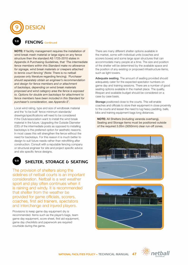
9
DESIGN
9.8 FENCING Continued
NOTE: If facility management requires the installation of wind break mesh material or large signs on any fence structure then the standard AS 1725-2010 states in Appendix A Purchasing Guidelines, that ‘The intermediate fence members within this Standard make no allowance for signage, wind break materials or creepers attached to tennis court fencing’ (Note: There is no netball purpose only literature regarding fencing). ‘Purchaser should separately obtain an engineer’s recommendation and design for fence members and or attachment of backstays, depending on wind break materials proposed and wind category area the fence is exposed to. Options for double arm backstays for attachment to fence members have been included in this Standard for purchaser’s consideration, see Appendix E’.
Local wind rating, type and size of windbreak material and the ‘to be built’ fence minimum standards/ drawings/specifications will need to be considered if the Club/association want to install the wind break material in the future. Upgrading the Outside Diameter (OD) of the intermediate posts as opposed to installing backstays is the preferred option for aesthetic reasons. In most cases this will strengthen the fence without the need for backstays. For this reason it is much better to design to suit future needs rather than retrofitting after construction. Consult with a reputable fencing company or structural engineer for site and project specific advice and site specific fence designs.
9.9 SHELTER, STORAGE & SEATING
The provision of shelters along the sidelines of netball courts is an important consideration. Netball is a wet weather sport and play often continues when it is raining and windy. It is recommended that shelter from the weather be provided for game officials, scorers, coaches, first aid trainers, spectators and interchange and injured players.Provisions to keep game day equipment dry is recommended. Items such as the player’s bags, team game day equipment, score sheet, first aid equipment, game day checklists and paperwork are required courtside during the game.
There are many different shelter options available in the market, some with individual units (coaches and scorers boxes) and some large span structures that can accommodate many people at a time. The size and position of the shelter will be determined by the available space and the position of any existing or proposed infrastructure items, such as light towers.
Adequate seating. The amount of seating provided should adequately cater for the expected spectator numbers on game day and training sessions. There are a number of good seating options available in the market place. The quality, lifespan and available budget should be considered on a case by case basis.
Storage positioned close to the courts. This will enable coaches and officials to store their equipment in close proximity to the courts and lessen the need to lug heavy padding, balls, bibs and training equipment bags long distances.
NOTE: All Shelters (including veranda overhang), Seating and Storage items must be positioned outside of the required 3.05m (3050mm) clear run-off zones.
CROSS FITTING – HDG
NATIONAL FACILITIES POLICY – 47TECHNICAL MANUAL

9
DESIGN
9.10 INCLUSIVITY, ACCESSIBILITY
& SIGNAGE
It is important that good netball facility design ensures netball courts, supporting infrastructure & amenity are welcoming, accessible & inclusive to all members of the community. It is important to provide;
Safe, firm and accessible pathways to connect the netball courts to the car park areas and other amenities such as clubroom, pavilion, changeroom and toilet facilities
Pedestrian circulation zones/walkways between or around courts in high pedestrian areas – these are in addition to the required obstacle free run-off zones
Safe surfaces to all paths, access areas, ramps and steps. All surfaces should be firmly fixed and slip resistant in wet and dry weather conditions
Clear informative and directional signage
Public lighting to path connections and car park areas
Car parking with accessible car park spaces in close proximity to the court and supporting amenity areas.
The information contained in this section should be used as a guide and specifically relates to outdoor netball courts. All design works should follow Universal Design principles and comply with the DDA Act 1992 and provide all abilities access as per Australian Standard AS1428.1-2009. Design should also comply with the current National Construction Code (NCC) Series 2012 vol.2 Building Code of Australia Class 1 and Class 10 Buildings where relevant. Other good practice documents in circulation should be considered along with local government and/or specific funding requirements for each individual project.
Pathways Pathways should consist of a hard pavement such as asphalt or concrete. These are preferred as they provide superior stability underfoot. If budgets are minimal, a firm stable path can be constructed using pavers or a granular type material, however, it is important to note that granular materials can be problematic and migrate onto the court surface, therefore creating possible slip hazards and higher court maintenance requirements.
Path connections should be wide enough for the intended use and be without trip and slip hazards. If gradient changes are an issue then ramp access should be provided. Paths should adhere to the current Disability Discrimination Act (DDA) and the Australian Standard AS1428.1-2009. Where access to and within buildings and stadiums is required the current National Construction Code (NCC) Series 2012 vol.2 Building Code of Australia Class 1 and Class 10 Buildings should also be referenced.
SignageIt is recommended that signage is provided to welcome, inform and reassure visitors. Signage should also:
Introduce & direct people to the courts & supporting facilities & amenities.
Signs should be obvious, clear & consistent throughout the facility.
Incorporate commonly used words & symbols that are easy to understand.
Placement is important:
Position where visually impaired people can get close to it.
Signs should not cause obstruction or create a safety risk.
Circulation/Movement ZonesThe provision of accessible circulation and movement zones is preferred wherever possible.
This includes:
1.5m wide Circulation Space between spectator/shelter/seating areas and the court run-off zones and
1.5m wide Movement Corridors between multiple courts and/or to the sides or ends of the courts.
These recommended spaces are in addition to the netball courts required obstacle free run-off zones. The aim is to keep the court’s run-off zones free of pedestrians and spectators whilst providing safe uninterrupted passage for pedestrians from the facility entrance to spectator areas and other courts and amenities within the facility while games are playing. Circulation and movement zones are particularly important in large multiple court facilities. These areas should be clearly marked to guide the players, officials and spectators safely through the facility without interrupting player or umpire movement. In the absence of an existing netball specific width recommendation for these circulation zones, it is recommended that the designer is guided by the DDA Act 1992 and relevant Australian Standards as stated above and aim to provide a minimum 1.2m wide (or 1.5m wide preferred) pedestrian movement /circulation zone in addition to the required run-off zones in high pedestrian movement areas and in front of spectator/shelter/seating infrastructure. See the compliant multiple court diagram in Section 2 ‘Compliance’ in this manual for a diagram depicting these preferred circulation/movement zones. As noted, this is a recommendation only and is provided to encourage greater facility performance and greater player, umpire and pedestrian safety, especially for large multiple court facilities. Budget and site constraints may determine that this ideal is not possible, however, it will greatly improve the functionality of a netball facility if considered.
TECHNICAL MANUALNATIONAL FACILITIES POLICY –48

9
DESIGN
9.11 LANDSCAPING
Landscaping is a very important part in the general appearance and attractiveness of a netball complex. Well-kept green court surrounds can also greatly reduce the amount of ongoing court maintenance required. A carefully installed irrigation system can assist, however, make sure that water from the irrigation system does not spray onto the court surfaces or encourage excess water to sit on or around the pavement areas. Additionally, there should be hose fittings placed so that each court surface can be washed without having to resort to long lengths of hose.
Drinking fountains placed at strategic positions can be of great benefit to players. Natural shade and made structures offer greater player and spectator comfort. Shelters should be placed along the sides of the courts for optimum vision for spectators and officials. It is very important that all parts of the shade structure, including veranda overhangs are placed outside of the required obstacle free run-off zones.
Be very selective when choosing landscape materials and vegetation. Do not plant large trees or plants that have invasive root systems within 10-15m of a court pavement. Existing tree limbs and shrubs should be kept trimmed or lopped away from the court pavement. Ongoing maintenance issues are caused by trees and shrubs planted too close to netball courts. Leaf litter drop, algae from shaded court areas, limb drop and tree root damage are just some of the issues you will want to avoid. Loose path materials such as blue metal, granitic sand etc can migrate or be carried on to the courts by the player’s shoes and should be avoided wherever possible.
An attractively landscaped netball centre can attract players. A regular inspection will detect areas that need attention or replacement.
NOTE: If plantings are considered, ensure a tree root barrier is installed along the planted boundaries to protect the pavement. Select small attractive non-invasive tree and shrub varieties that have minimal leaf, berry or flower drop. Look for attractive small bushes and shrubs that are compatible with the soil and climatic conditions of your area. Low maintenance and low water dependant plants are desirable.
9.12 COURT SURFACE
The selection of a netball court surface is critical to the overall playability & enjoyment of the netball court. It must be fit for purpose and outdoor courts should be safe for all weather netball play.
9.12.1 COURT SURFACE TYPES &
SLIP RESISTANCE TESTINGIn Australia there are generally five (5) types of netball surfaces in use:
Timber Sprung Floor courts (Netball Australia’s Preferred Indoor Surface)
Acrylic surfaced hard courts – non-cushioned (basic) and Cushioned Types (Netball Australia’s Preferred Outdoor Surface)
Asphalt hard courts
Natural grass courts
Synthetic grass courts.
As stated above the Timber Sprung Flooring system is recommended for indoor courts and Acrylic systems that offer good slip resistance in wet conditions are recommended for outdoor courts.
TestingThere are currently two main identified standards for the testing of slip resistance properties in sports acrylic surfaces for netball courts. These are:
1 Achieving a temperature correction value (TCV) for a mean British Pendulum Number (BPN) of at least 75 for wet slip resistance testing - in line with AS 4663:2004 Slip Resistance measurement of existing pedestrian surfaces.
2 AS 4586-2013 Slip Resistance Classification of New Pedestrian Surface Materials: Appendix A (Wet Pendulum Test Method) achieving a P5 Classification as a minimum.
In the absence of any formal testing by Netball Australia and any official adoption of a set testing standard by Netball Australia, project sponsors are encouraged to research the two different recognised testing methods and decide which of the 2 is the most appropriate for their individual application.
There are known acrylic surfacing companies that are meeting Item 1. above being a BPN of 75 or greater and therefore clubs, associations and Councils may want to aim for this higher slip resistance value where possible.
NATIONAL FACILITIES POLICY – 49TECHNICAL MANUAL

9
DESIGN
9.12.1 COURT SURFACE TYPES & SLIP RESISTANCE TESTING Continued
Clubs, Associations, Leagues and Councils should ensure that the contractor provides a warranty that stipulates their approved products slip resistance value and the number of years they guarantee the slip resistance properties will achieve this for. The products value stipulated by the contractor should be in line with the required P5 classification or the BPN of at least 75 – whichever is adopted and specified for the individual project.
Note: It is important that the preferred slip resistance standard requirements be stipulated in the project brief/specification. This should be the contractor’s responsibility to achieve and treated as a true project cost.
Testing by a company accredited by the National Association of Testing Authorities (NATA) is recommended.
NATA accredited slip resistance testing companies are available throughout Australia.
A minimum of five (5) individual locations should be slip resistance tested on each playing court using both slider 55 and slider 96 and shall achieve Pendulum Classification P5 or the BPN of at least 75 as a minimum for both sliders. As netball is played in both dry and wet weather, testing should be completed in both wet and dry conditions.
Indoor courts are not playable when they are wet and therefore it is logical that they should be tested in dry conditions.
Outdoor courts should be playable in both wet and dry conditions and therefore should be tested for both wet and dry conditions.
This slip resistance testing is not appropriate for all court surfaces. For example, some testing equipment will not report on synthetic grass or natural grass courts. These types of surfaces offer minimal slip resistance in wet conditions and therefore it is recommended that competition play not be allowed in these conditions.
Surface TypesWhen selecting a surface, it is essential that Councils, Clubs or Associations consider all elements including the advantages and disadvantages of the different surfaces/products before choosing the ideal surface. The different court surfaces are outlined as follows;
Double Sprung Timber Floor – Known as the premier indoor surface:
Advantages: Excellent slip resistance in dry conditions and with a very long life span – used indoors for netball competition including the highest level of competition (international). Offers multi-sport use.
Disadvantages: Limited to indoor use only.
Acrylic Surfaced Hard Courts – See the following extended sections
Asphalt Hard Courts – A bare asphalt base
Advantages: Affordable as there is no additional acrylic surfacing required. It has good slip resistance in wet and dry conditions.
Disadvantages: The asphalt will break down prematurely without the protection of a protective surface, such as acrylic. Therefore, the renewal rate of the base can be greater and more costly. Small stones may dislodge from an aged asphalt surface, regular removal may be required.
Natural grass courts – Found in the warmer regions of Australia
Advantages: Affordable courts for junior players in warmer regions.
Disadvantages: Has very limited slip resistance. Should not be played on when wet.
Synthetic grass courts – Indoor or multipurpose facilities
Advantages: Affordable courts for indoor netball or multipurpose facilities
Disadvantages: Has limited slip resistance. Should not be played on when wet.
NOTE: Sand Filled Artificial Grass (SFAG’s) which are common with outdoor tennis courts are not recommended for netball.
Only proven acrylics or cushioned acrylics backed with a manufacturer’s warranty should be considered by Clubs, Associations, Leagues and Councils. Generally in Australia there are three types of acrylic surfacing systems: Non-cushion, Liquid applied cushion and Mat laid cushion.
TECHNICAL MANUALNATIONAL FACILITIES POLICY –50

9
DESIGN
9.12.2 ACRYLIC HARD COURT
– NON-CUSHION
Non-Cushion – This Acrylic is simply 3-4 acrylic coatings (combination of filler & top coats) applied on concrete or asphalt pavements:
Advantages: Affordable sports surface with excellent slip resistance in wet/dry conditions
Disadvantages: Needs resurfacing every 7-10 years (depending on use) to maintain optimum slip resistance, playability and base protection. Slip resistance, playability and longevity is subject to brand and/or quality of the acrylic surfacing product used on Acrylic hard courts are very common and widely used; it is by far the most popular surface for outdoor netball due to its affordability. A non-cushion (basic) acrylic sports surface will reflect damage (such as cracks & pyrite damage) in the asphalt or concrete base it is installed on.
Acrylic hard courts are generally 3–4 coats depending on the base (asphalt or concrete). When a bare concrete or asphalt surface needs to be coated it is important to identify the condition as to ascertain the number of coats required. This will help during the budgeting process.
As a basic rule of thumb, Clubs and Associations should apply the following:
Asphalt base – 3 to 4 coat system depending if it’s a tight dense finish or open and bony weathered asphalt
Concrete base – 3 to 4 coat system depending on new or weathered concrete
Existing acrylic recoat – 2 coat system.
9.12.3 LIQUID APPLIED CUSHION
Liquid Applied Cushion (Wet Laid) is a cushioned system designed for concrete or asphalt. They are a combination of multiple layers of rubber-filled acrylic resin coatings sandwiched between the base/filler coats and the playing surface topcoats:
Advantages: Excellent slip resistance in wet/dry conditions with cushioning
Disadvantages: Due to the application method, it can create inconsistency between courts. The binders in many products available in the market can breakdown over time losing the cushioning properties. The installation of additional cushioned layers may be required when resurfacing
The cushion system is also known as a “Wet Lay” system and can range from an 8 coat system with a nominal thickness of 1–2mm up to a 12 coat system with a nominal thickness of 3–5mm. (Due to the application method of using a squeegee to apply the rubber, only nominal thicknesses at best can be achieved).
The wet lay system consists of 2 types of rubber granules:
Liquid Rubber Coarse (LRC) – Used to give the surface body and a base for the nominal thickness
Liquid Rubber Fine (LRF) – Used to fill in the voids and to give a smooth and even surface.
This system is applied in layers and spread with a rubber squeegee over the entire surface. Some applicators may use a notched squeegee for the first coat that is primarily set at the desired depth for even coverage and consistency but ultimately it is up to the applicator and their level of skill and experience that determines the method used.
Line marking
Player surface x 2
Acrylic filler coat x2
Asphalt base
Concrete base
Concrete base coat
Line marking
Filler coat x2Player surface x 2
Liquid rubber coats x2
Base coat x2
Concrete or asphalt base
NATIONAL FACILITIES POLICY – 51TECHNICAL MANUAL
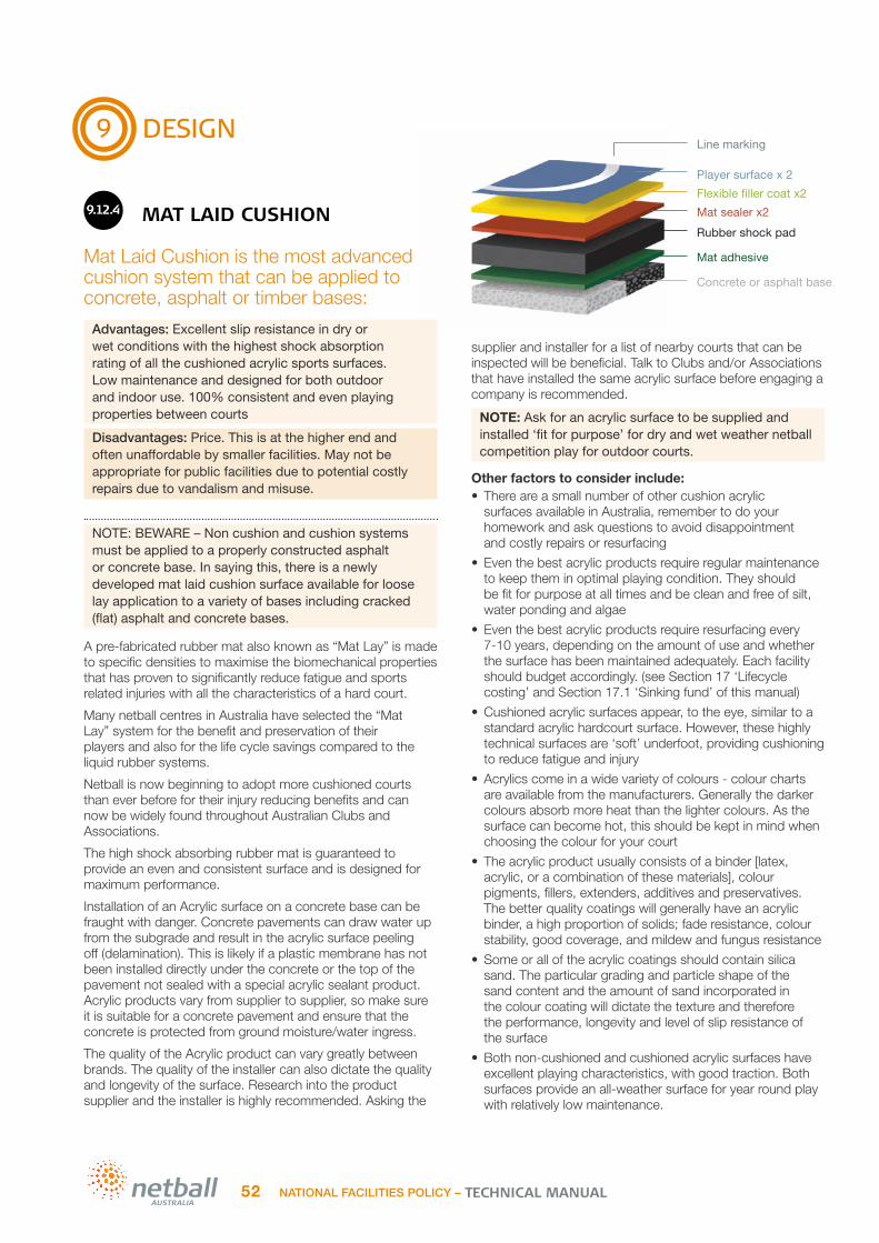
9
DESIGN
9.12.4 MAT LAID CUSHION
Mat Laid Cushion is the most advanced cushion system that can be applied to concrete, asphalt or timber bases:
Advantages: Excellent slip resistance in dry or wet conditions with the highest shock absorption rating of all the cushioned acrylic sports surfaces. Low maintenance and designed for both outdoor and indoor use. 100% consistent and even playing properties between courts
Disadvantages: Price. This is at the higher end and often unaffordable by smaller facilities. May not be appropriate for public facilities due to potential costly repairs due to vandalism and misuse.
NOTE: BEWARE – Non cushion and cushion systems must be applied to a properly constructed asphalt or concrete base. In saying this, there is a newly developed mat laid cushion surface available for loose lay application to a variety of bases including cracked (flat) asphalt and concrete bases.
A pre-fabricated rubber mat also known as “Mat Lay” is made to specific densities to maximise the biomechanical properties that has proven to significantly reduce fatigue and sports related injuries with all the characteristics of a hard court.
Many netball centres in Australia have selected the “Mat Lay” system for the benefit and preservation of their players and also for the life cycle savings compared to the liquid rubber systems.
Netball is now beginning to adopt more cushioned courts than ever before for their injury reducing benefits and can now be widely found throughout Australian Clubs and Associations.
The high shock absorbing rubber mat is guaranteed to provide an even and consistent surface and is designed for maximum performance.
Installation of an Acrylic surface on a concrete base can be fraught with danger. Concrete pavements can draw water up from the subgrade and result in the acrylic surface peeling off (delamination). This is likely if a plastic membrane has not been installed directly under the concrete or the top of the pavement not sealed with a special acrylic sealant product. Acrylic products vary from supplier to supplier, so make sure it is suitable for a concrete pavement and ensure that the concrete is protected from ground moisture/water ingress.
The quality of the Acrylic product can vary greatly between brands. The quality of the installer can also dictate the quality and longevity of the surface. Research into the product supplier and the installer is highly recommended. Asking the
supplier and installer for a list of nearby courts that can be inspected will be beneficial. Talk to Clubs and/or Associations that have installed the same acrylic surface before engaging a company is recommended.
NOTE: Ask for an acrylic surface to be supplied and installed ‘fit for purpose’ for dry and wet weather netball competition play for outdoor courts.
Other factors to consider include:• There are a small number of other cushion acrylic
surfaces available in Australia, remember to do your homework and ask questions to avoid disappointment and costly repairs or resurfacing
• Even the best acrylic products require regular maintenance to keep them in optimal playing condition. They should be fit for purpose at all times and be clean and free of silt, water ponding and algae
• Even the best acrylic products require resurfacing every 7-10 years, depending on the amount of use and whether the surface has been maintained adequately. Each facility should budget accordingly. (see Section 17 ‘Lifecycle costing’ and Section 17.1 ‘Sinking fund’ of this manual)
• Cushioned acrylic surfaces appear, to the eye, similar to a standard acrylic hardcourt surface. However, these highly technical surfaces are ‘soft’ underfoot, providing cushioning to reduce fatigue and injury
• Acrylics come in a wide variety of colours - colour charts are available from the manufacturers. Generally the darker colours absorb more heat than the lighter colours. As the surface can become hot, this should be kept in mind when choosing the colour for your court
• The acrylic product usually consists of a binder [latex, acrylic, or a combination of these materials], colour pigments, fillers, extenders, additives and preservatives. The better quality coatings will generally have an acrylic binder, a high proportion of solids; fade resistance, colour stability, good coverage, and mildew and fungus resistance
• Some or all of the acrylic coatings should contain silica sand. The particular grading and particle shape of the sand content and the amount of sand incorporated in the colour coating will dictate the texture and therefore the performance, longevity and level of slip resistance of the surface
• Both non-cushioned and cushioned acrylic surfaces have excellent playing characteristics, with good traction. Both surfaces provide an all-weather surface for year round play with relatively low maintenance.
Line marking
Player surface x 2Flexible filler coat x2Mat sealer x2Rubber shock pad
Mat adhesive
Concrete or asphalt base
TECHNICAL MANUALNATIONAL FACILITIES POLICY –52

9
DESIGN
9.12.5 SURFACE ADVANTAGES AND DISADVANTAGES
A netball Club focussed on the development and well-being of their players may choose any of the non-cushion and cushion systems. The cushioning benefits and playing characteristics of the wet lay, mat lay or timber surfaces may come at a cost but the benefits are obvious.The previously stated outdoor surface systems are designed for low maintenance. However, routine maintenance is still required.
Many netball courts are in large open areas with no shade and in unfenced public parks which are vulnerable to abuse
and vandalism. A cushion system may not be appropriate due its capital cost and its repair cost associated with misuse or damage of the courts. Therefore, consideration should be given to a sports surface that suits the facility location and type of use (member or public access).
Only proven acrylics or cushioned acrylics backed with a manufacturer’s warranty should be chosen by the Clubs or Associations. Low maintenance, longevity, easy to repair and cost effectiveness are the main points to identify.
There are a number of acrylic products in the Australian market. Some of the leading acrylic systems are outlined as a guide in the table shown on the next 3 pages.
NATIONAL FACILITIES POLICY – 53TECHNICAL MANUAL

9
DESIGN
9.12.5 SURFACE ADVANTAGES AND DISADVANTAGES Continued
Acrylic Court Surface Systems
Plexipave (AUS/Netball)Plexipave is an acrylic multi-layer coating system. Generally applied in three or four coats with a combination of filler and finish coats that’s suitable for hot mix asphalt or suitably prepared concrete. The result is a durable, richly coloured non glare surface providing a uniformed texture suitable for netball venues.
Based on 100% acrylic water based coatings, the Plexipave System dries rapidly and allows surfaces to breathe enabling moisture vapor to pass through the dried film.
Rebound SynpaveSynpave provides a durable, economical, high performance surface which retains its colour and performance properties for years despite heavy use and extremes of weather and temperature.
Fully manufactured in Australia, Rebound Synpave is based on pure acrylic resins, proven and tested for in excess of 30 years in the marketplace and is fully biodegradable and water-based. The Synpave topcoat formulation provides excellent slip resistance qualities suitable for netball venues.
Laykold AdvantageLaykold Advantage is a 3-4 coat acrylic sports surface comprised of factory textured colours using a select blend of silica sands. Batch mixing is simplified, resulting in superior quality control and a constant surface performance regardless of location or applicator. Laykold Advantage is environmentally friendly and does not contain lead, mercury or asbestos. The wide variety of colours are UV stable and long lasting.
Easily maintained, which may include the provision of an annual high pressure wash; Most acrylics can be simply and economically recoated.
Can also be upgraded by adding cushion layers – either wet-laid or pre-formed (as per the following options)
Left uncoated, asphalt will oxidise due to UV exposure and weathering. Stones loosen and the surface becomes abrasive, causing player injury & discomfort when falls occur. By applying an acrylic coating to existing court surfaces, you are in effect giving it a sunscreen that preserves its lifespan for a fraction of the cost of a new asphalt surface.
HARD COURTS BASIC
ACRYLIC
Line marking
Player surface x 2
Acrylic filler coat x2
Asphalt base
Concrete base
Concrete base coat
i
Line marking
Fortified PlexipaveAcrylic resurfacer
Concrete or asphalt
Line marking
Acrylic resurfacer
Concrete base only
Advantage Laykold®
colour
Laykold®
Epoxy Concrete Primer
TECHNICAL MANUALNATIONAL FACILITIES POLICY –54

9
DESIGN
9.12.5 SURFACE ADVANTAGES AND DISADVANTAGES Continued
Acrylic Court Surface Systems
Plexicushion PRESTIGEThe Official Surface of the Australian Open Grand Slam tennis event, can also be tailored to suit netball’s unique playing requirements. Plexicushion is a special blend of latex, rubber and plastic particles, forming a resilient layer that absorbs body shock and reduces muscle fatigue. The surface texture options of the 100% acrylic Fortified Plexipave finish coats means it can be tailored to provide the slip resistance qualities required for outdoor netball facilities.
Rebound PRO Rebound PRO cushioned acrylic surfacing provides a high performance surface for sport surfaces at the professional, amateur and social level. The resilient cushion provides a sure comfortable feel underfoot and is easier on the body than non-cushioned hard court surfaces. Utilising a specially formulated netball topcoat, the playing surface also provides excellent grip – even in wet conditions for outdoor netball facilities.
Laykold Cushion PlusThe Laykold Cushion Plus series are a 9-12 coat cushioned system. The multiple layers of rubber are encapsulated within a highly flexible proprietary 100% acrylic binder. The firm, yet resilient, uniform footing for unsurpassed safety delivers a more comfortable play and post-play experience.
The Laykold Cushionplus series are environmentally friendly and do not contain lead, mercury or asbestos. The wide variety of colours are UV stable and long lasting
Wet-laid / liquid-applied cushioned court systems combine multiple layers of rubber-filled acrylic resin coatings sandwiched between the base/filler coats and the playing surface topcoats. CUSHIONED
COURTS WET/LIQUID
SYSTEMS
Line marking
Player surface x 2Filler coat x2
Liquid rubber coats x2
Concrete base
Base coat x2
i
Line markingFortified Plexipave
Acrylic resurfacer
Concrete or asphalt
Plexicushion
Line marking
Acrylic resurfacer
CushionPlus PowderCushionPlus Granule
Concrete base only
Laykold®
Colourflex
Epoxy Concrete Primer
NATIONAL FACILITIES POLICY – 55TECHNICAL MANUAL

9
DESIGN
9.12.5 SURFACE ADVANTAGES AND DISADVANTAGES Continued
Acrylic Court Surface Systems
No products in the Plexi range
Rebound Ace HSA ClubRebound Ace HSA Club provides the perfect balance between firmness under foot & player comfort levels. Combining a polyurethane bound 4mm rubber granulated shock pad with Rebound Ace Sports specially formulated netball topcoat technology; it can extend the playing-life of netballers at all levels of the sport.
No products in the Laykold range
Netball is a physically demanding sport, with impact injuries to player’s rotational joints & ligaments at the time of landing, a common & unfortunate side effect…until now.
It stands to reason that the advanced cushion characteristics inherent in the pre-formed rubber shock-pad layer, provides greater impact absorption than typical hard courts.
CUSHIONED COURTS
MAT SYSTEMS
i
Line marking
Player surface x 2Flexible filler coat x2Mat sealer x2Rubber shock pad
Mat adhesive
Concrete or asphalt base
TECHNICAL MANUALNATIONAL FACILITIES POLICY –56

9
DESIGN
9.12.6 INDOOR COURT FLOORING
A timber sprung flooring system is recommended for indoor netball.Timber sprung floors have been synonymous with basketball for many years and throughout time have been adopted for netball. There are various timber floors on the market today that suit all types of budgets. The timber floor varieties have their strengths and their weaknesses so it is essential that you consult the experts before you make your choice.
When selecting an indoor surface it is essential that the product suits the Clubs/association requirements. To select a surface suitable for one sport only is limiting the potential and a revenue stream for the user groups. For example; if a netball club was to choose a timber surface it will cater well for both netball and basketball in addition to a variety of other indoor sports.
Indoor surfaces are designed flat and level as they are not exposed to the outdoor weather conditions. All indoor court surfaces must be kept clean and dry for netball use to minimise slip hazards.
Other indoor surfaces include PU cushioned systems. These provide elasticity that can offset impact forces like a shock absorber – potentially reducing the risk of injury, however timber sprung floors are recommended.
When researching these products, and particularly if it’s for a multipurpose centre, it is handy to have a check list, for example:
Surface Requirements
Suitable for a variety of indoor sports i.e.; netball, basketball, volleyball, futsal
Durable and long wearing
Low maintenance and easy to clean
Solvent free installation
Free of toxic fumes
Water based technology
Player Performance Requirements:
Promotes player development
Reduces strains and sports related injuries
Consistent surface underfoot
NATIONAL FACILITIES POLICY – 57TECHNICAL MANUAL

10
CHOOSING A CONTRACTOR
Netball Australia cannot recommend specific contractors or service providers as the checking process required would be extensive, constantly changing and difficult to manage.Netball Australia can, however, recommend that Clubs and local governments do the following to minimise the risk associated with selecting a contractor:
Obtain technical guidance
Prepare a technical specification and design package
Request tenders or quotes from the construction industry
‘Compare apples with apples’ when choosing between tenderers
Ensure appropriate contracts and project acceptance.
10.1 GET A QUOTE
Once you have decided to build new courts or repair and upgrade your existing courts, your first action is to get quotes, right? This is a common mistake that Councils and Associations make every day.
What a reputable contractor will include in their quote, an unqualified contactor may not - this can result in a big difference in the price. The best and easiest way to safe guard your money and minimise the risk of ending up with a poor job is to write a specification to set the project standards.
To write a successful specification you must first identify the underlying problem with the facility and then know the right solution to accurately fix it. Again, let the costs of the repairs determine the budget and don’t let the budget determine the costs of repairs.
Note: Don’t rush – Get the sound professional advice you need first and then approach the contractors.
10.2 OBTAIN TECHNICAL GUIDANCE
There are very few independent, professional design groups/consultants that have this specialised expertise with regards to all aspects of a typical netball court related project. Therefore, the best source of such information will generally be the relevant State/Territory Member Organisation.
These bodies generally have access to expert advice and technical consultants. They may also have access to other vitally important professionals with a wealth of experience in specific aspects of netball courts, such as Geotechnical Engineers, Electrical & Lighting Engineers, Civil / Structural Engineers and Court Surfacing Specialists.
10.3
PREPARE A TECHNICAL SPECIFICATION & DESIGN PACKAGE
It is recommended that the Club, Association or Council engages an industry expert to prepare the detailed design and specification so there’s no confusion or misrepresentation.
A civil engineer should always be engaged to design a netball court construction. This design should include a suite of drawings outlining the pavement detail, levels, drainage detail and supporting infrastructure detail. This will be used in the tender/quoting stage and throughout construction.
A detailed specification document should accompany the detailed design drawings. This outlines the terms and conditions and contains a detailed outline of the works required and the schedule of quantities and rates for the contractors to price.
A good design and specification package will have the following:
A well prepared technical specification that clearly details the required scope of works. This will minimise disputes during or at the completion of the construction as to what the intended scope of works were.
A detailed design drawing package provided by a civil engineer or independent consultant (for major or reconstruction works).
A detailed Bill of Quantities or a Schedule of Rates. This document should itemise all the works required so that all contractors pricing the project are doing so on the same basis, thereby providing a set criteria to compare the quotes received.
Note: Australia is littered with netball courts in poor and unsatisfactory condition due to a poor design/specification produced or no design/specification package at all. Do not make the same mistake.
When you don’t issue a specification, you are effectively allowing the contractors to determine the level, quality and amount of materials and workmanship they think is required. This can create low project costs but result in a poor outcome.
TECHNICAL MANUALNATIONAL FACILITIES POLICY -58

10
CHOOSING A CONTRACTOR
10.4 REQUEST TENDERS OR QUOTES FROM THE CONSTRUCTION INDUSTRY
Unfortunately, as with most other sectors in the construction industry, there can be less desirable contractors in the marketplace. Some can have little understanding of the technical aspects of netball court construction and can underestimate the special requirements of a sports pavement.
So why do netball court owners or managers continue to find themselves in this situation?
Generally it is a question of money. Some contractors can offer significantly lower prices to construct their courts in comparison to their more recognised and higher quality competitors. Given that many clubs/associations struggle to raise funds to undertake works, the temptation to minimise their outlay is often very appealing.
The old adage that “you get what you pay for” is particularly relevant when it comes to netball court construction. On the other hand the more reputable contractors may be able to offer competitive rates due to their buying power.
By following some basic processes, common mistakes can be avoided:
Do Your Homework Take the time to research the contractors and choose wisely. Ask other Clubs and Councils who they used, do background checks on references and go and see some of their completed projects in person. Asking the following questions may assist:
• Is the contractor experienced and have they completed many similar projects to a high standard?
• Was the contractor good to work with, professional, good on communication and timelines?
• Did they construct the project within their tendered price or did they sting the client on variations?
• Have they been easy to contact and attentive after construction? Did they address all reported defects during the defects liability period within a timely period and without fuss?
• Did they achieve a high quality finish to the court and surrounds?
• Has the court had any signs of failure since project completion and if so what is the contractor doing about it?
Price Choosing a contractor based on the cheapest quotation is not necessarily the best in the long term:
• You certainly do not want to accept the lowest price and end up with unplayable courts in a few short years because the cheapest contractor didn’t build them as well as the slightly more expensive contractor would have – major crack repairs and reconstructions are very expensive - again do your homework to avoid this.
• Assessing the ‘value for money’ instead of ‘price’ alone is recommended at the quotation or tender assessment stage. This considers the long term value of your investment not just the initial construction phase.
Sub-Contractors A principle contractor/company will often outsource different trades to complete a project.
• For example, fencers, acrylic surface applicators and concreters. It is very important to find out who they intend to use to complete the netball court project – ask them for a list of their sub-contractors. Ensure they are experienced and have a good reputation in the industry by again doing your homework and asking local clubs and your local council. This is especially important for the court base and surfacing works.
• A potentially great project can easily end up being the worst as a result of just one bad sub-contractor.
Insurance, Warranties & Occupational Health & Safety (OH&S)• Insurance – Contractors can carry multiple
insurances depending on the size of their company. This can include personal, vehicle and/or workers compensation. It is essential that the contractor carry a Public Liability Insurance with an accepted standard minimum value of $10,000,000.
• Installation Warranty - All works performed by the contractor must have a warranty against failures for a reasonable time frame. Reputable contractors will offer installation warranties for a reasonable time frame of 3–5 years + as standard practice. The longer the better!
• Product Warranty – The product must also contain a warranty that is NOT issued by the contractor, as happens in many cases, but directly and independently from the manufacturer. Product Warranties are commonly issued in a certificate or official letter form when requested. This should be requested in the specification and provided by the contractor upon project completion/handover.
• OH&S – Reputable contractors will have a prepared OH&S package including Safe Work Method Statements (SWMS) for their proposed works, products & machinery. Councils often require these as a mandatory requirement in tender submissions.
Note: When requesting a quotation from contractors give them at least 2-3 weeks to review the project design and/or specifications package. This allows sufficient time to review and comprehend all the documentation provided as well as obtain any prices they may require from their suppliers and/or sub-contractors.
NATIONAL FACILITIES POLICY - 59TECHNICAL MANUAL

10
CHOOSING A CONTRACTOR
10.5 ‘COMPARE APPLES WITH
APPLES’ WHEN CHOOSING BETWEEN TENDERERS
This process can be made considerably easier if all quotes are based on a clear and well detailed design, project specification and, as mentioned previously, a well compiled Bill of Quantities/Schedule of Rates. This can assist when comparing the tender submissions/quotes as it is much easier comparing apples with apples.
Note: If a design and construct method is adopted, it may be very difficult to compare each contractor and even more difficult to ascertain if the contractor’s submitted price is for an adequate for the particular site or not. The market is very competitive and contractors can price and win a job based on a bare minimum construction standard where a more substantial standard was needed. This can lead to premature pavement failure and very unsatisfied Clubs, Associations, Leagues & Councils.
As stated in Section 9 ‘Design’ of this manual, an independent engineers design considering the soil & site conditions & using industry best design principles may offer the Club, Association, League or Council the greatest surety of a quality long term outcome.
Consideration should also be given to the contractor’s performance on recent projects (based on their references), the demonstrated quality of their workmanship (as evidenced from inspections of previously completed projects) and your own impressions from communications up to this point (and references obtained).
Depending upon the emphasis placed on each of these criteria, the choice may be simple or very difficult. On larger projects or local government run projects, it is not uncommon for each of these criteria to be given a weighting (say 40-50% for value for money, 20% for previous performance / references, 20% for demonstrated experience & workmanship and 10% for local engagement). The weightings for each of these items (and others that may be applicable to your project) can be modified to reflect the nature of the project and priorities.
Each tender/quote submission is then marked against each of these weighted criteria so as to arrive at the “best” value for money offer. Having undertaken this exercise, it is possible that the leading two or more contractors require an interview to arrive at a preferred contractor. This is an opportunity to confirm project specifics and/or discuss key areas of concern with regards to each submission.
There may be alternative methods of reviewing and recommending a tender submission/quotation, however, it will generally be along the lines of the process outlined above.
Note: Take your time and choose wisely!
10.6 ENSURE APPROPRIATE
CONTRACTS AND PROJECT ACCEPTANCE
Once a decision has been made to accept a contractor’s quotation or tender, the next step is to advise them of your intention to accept their offer and advise all other contractor’s that their bids have been unsuccessful. This allows both the successful and unsuccessful contractors to either begin planning and preparations for works or to move on.The next step is to come to an agreement with the successful contractor on a set of contract conditions that you can both work with. If the contractor nominated a specific form of contract in their quotation, this needs to be taken into consideration when comparing this tender with others received. If there is a specific form of contract that is required by the club/association or council, it could be nominated in the project specification and provided to contractors during the tender/quotation period.
TECHNICAL MANUALNATIONAL FACILITIES POLICY -60

11
PROJECT MANAGEMENT
Many Clubs and Associations have tried to manage the design and construction stages of their projects with varying degrees of success. Some Clubs and Associations are fortunate enough to have had a committee and/or Club member/s with sufficient skills to manage this task. A project can take anything from a few months to a few years to progress from the feasibility stages right through to the completion of construction. At times this can be a very time consuming role, and given most Clubs rely on volunteers, this can impact on the ability of these people to maintain control and progress the development through to completion.Whilst many of these people are familiar with the basic requirements of a netball court and associated ancillary structures, many have very little comprehension of the specialist engineering knowledge that is required in the design of such structures. Some of these design considerations will be discussed in detail throughout this manual to give the average club member at least a rudimentary understanding of these requirements.
There are all too many horror stories of courts that have been built without taking into account the prevailing soil conditions, insufficient provisions for site drainage, using the wrong materials, poor construction practices or even misunderstanding the compliance requirements, standards and local government regulations. A failure to take some or all of these sorts of issues into account can lead to substantial or even catastrophic failures of the courts themselves, all in a relatively short space of time.
Significant ongoing maintenance costs or rectification works could end up being as expensive as the original installation costs or more, especially if it means demolition and starting again. In many instances, these Clubs and Associations would have been far better off engaging a specialist Project Manager to oversee their project to ensure they are not exposing themselves to such risks
For the sake of a small proportion of the overall development costs, the engagement of a well-qualified Project Manager should considerably minimise their client’s risk exposure. Not only could a good project manager save these bodies from costly mistakes during design and construction, they should also be able to provide advice regarding life cycle costing issues, which are equally important to all court owners. (see Section 17 ‘Lifecycle costing’ and Section 17.1 ‘Sinking fund’ in this Manual). The last thing a client wants, after outlaying
good money for their facility, is to be burdened with the heartache of considerable ongoing maintenance and repair costs for many years to come due to ill-conceived decisions made during design development.
The nominated project manager should have the ability to inspect the contractor’s work at various key points during construction. These intended key points or ‘hold points’ should be identified in the project specification so that the contractor is aware of the process and can plan the inspections. The contractor should not proceed with any further works on the project until the works at each hold point have been inspected and approved.
An example of a typical netball court project hold point would be the provision of soil compaction test results to demonstrate that the prepared sub-base (crushed rock layer(s)) meets the specified compaction requirements and is therefore suitable for subsequent base construction works to commence. Another example would be an inspection of the pre concrete pour inspection which includes approval of the under slab plastic membrane, tied reinforcement mesh, bar chairs, construction joints and edge formwork prior to concrete pour.
If for any reason, the works up to each Hold Point stage are not of an acceptable standard, the contractor should be instructed to rectify this situation in accordance with the project specification requirements before proceeding to the next construction phase. The best-placed person to make these inspections will be the person who wrote the specification documents relating to that aspect of the works, or a competent project manager with a professional background relevant to the works they are inspecting. For example, the completed civil/earthworks and associated test results should be reviewed and approved (or otherwise) by the Design Consultant, Civil or Geotechnical Engineer who prepared the plans and specification for this aspect of the works (if required).
Regular hold point and spot inspections should minimise the risk of poor workmanship or building practices that may arise during construction. It is far better and more cost effective for all parties if potential issues are corrected throughout the construction stage rather than post construction. This is particularly important for any “in ground” problems that subsequently get “built over” in the natural course of events.
As previously stated in the ‘Where to get Further Help’ section of this manual, the best and most up to date advice is likely to be available by contacting the relevant State/Territory Member Organisation. Some states have a Technical Services Team who may be able to offer services from expert advice on simple issues right through to full Project Management of major capital works projects.
NATIONAL FACILITIES POLICY - 61TECHNICAL MANUAL

12
COURT CONSTRUCTION – PAVEMENT
The most important design and construction element of a netball court is the pavement. The court will be rendered unplayable if the base fails. The expense to rectify a failed pavement requires the dismantling of other elements, namely the surface, goal posts, light towers, fencing. This can cost more than the initial cost of constructing the courts.
NOTE: During this phase of construction there are no shortcuts! The recommendations outlined in the Design and Construction sections of this manual should be considered to achieve a successful project outcome.
12.1 CUT AND FILL
When the site is on uneven or sloping ground, the high areas will need to be cut and the low areas filled to create a level platform. The fill used must be compactable. It is imperative that ‘cut and fill’ sites are compacted well, as per the engineers recommendations and in layers with no more than 150mm maximum thickness from the cut location or using imported fill or granular materials. This is essential to ensure a stable platform is provided.
Stormwater must be channelled away from the filled slope via a spoon drain or kerb outside the runoff area to avoid erosion. See Section 12.5 ‘Drainage’ in this manual for more details.
Where retaining walls are required, appropriate drainage both behind and in front of the wall will be required to achieve a long lasting pavement. There are many types of retaining walls available and each individual site & budget will determine the type used. Retaining walls may require a building permit. It is important to seek advice from a civil or structural engineer for retaining wall detail specific to the individual netball court project.
12.2 PAVEMENT PLATFORM
The platform created should be longer and wider than the total area of the courts (including runoffs) where it should slope away from the intended pavement area in all directions.
The court platform is cut to remove all top soil and provide a firm base. The depth and level of the cut will be dependent on the depth of the pavement structure the civil engineer has designed so that the finished court levels required are achieved. The court platform should also reflect the drainage fall required, being; either a 1% cross fall in both directions or 1% fall diagonally on a single plane.
To achieve the right plane a laser leveller is used to create the desired falls once the platform has been cut.
12.3 SUBGRADE PREPARATION
The preparation and compaction of the sub-grade is crucial in achieving a long lasting court pavement.
Firstly the site must be cleared of all vegetation, topsoil and any saturated foundation materials to establish a firm court platform on which to construct the pavement. The sub-grade depth is dependent on the final excavation depth required to locate the firm base layer in which to build up from. The subgrade should reflect the fall required in the finished pavement, be free of tree roots, foreign objects such as old drainage pipe, uncompactable material and the like. It should be trimmed and rolled ready for proof rolling. In situations where trees need to be cleared, the roots must also be removed. In these situations the earth placed in the void must be compacted to ensure filled areas match the condition of the natural ground. The void area to be filled must be built up in layers with each layer compacted as it is placed. The thickness of each layer depends on the type of machinery used. The layers can vary from 100mm to a maximum 150mm depth depending on the compaction equipment being used.
During the compaction process, the FCR (Fine Crushed Rock) is spread out by the use of a small grader, bobcat or similar machinery and then compacted with a smooth drum roller. It is critical to maintain the moisture content to the recommended tolerances to achieve maximum compaction.
TECHNICAL MANUALNATIONAL FACILITIES POLICY -62

12
COURT CONSTRUCTION – PAVEMENT
12.3 SUBGRADE
PREPARATION Continued
The subgrade layer should be proof rolled and checked by the Project Manager to identify any “soft spots”. Proof rolling is a process whereby a fully-loaded (20 tonne) truck passes in runs across the prepared pavement area. Any signs of surface displacement (cushioning) should be marked and quantified for rehabilitation. In severe cases a civil engineers inspection and advice will be required to obtain the correct rehabilitation technique for the failed area.
An engineer is likely to require a minimum 95% standard compaction for natural subgrade and 98% modified compaction for any imported granular (fine crushed rock) filling.
The compaction testing should be carried out by a certified testing company to ensure the required compaction levels have been achieved. The reports should be kept on file for future reference.
If a stable subgrade cannot be achieved, the subgrade may need to be stabilised. In this case, advice should always be sought from the designing civil engineer.
In most cases the geotechnical (soil test) report obtained in the investigation/design phase of the project will indicate the likelihood of issues within the subgrade. However, it is important to note that a Geotechnical test will only test a select number of 100mm diameter locations per court. There are Australian Standards that can provide guidance on the correct number of test holes required for any given pavement size. It is impossible to test every inch of the pavement area and therefore soft spots and isolated unstable ground can go undetected until the site is excavated, prepared and proof rolled. Variations to the project can quite often occur at this stage of the project and therefore a good contingency should be allowed for in the budget. For more information regarding Budgets and Geotechnical testing see Section 7 ‘Budget & Funding’ and Section 8 ‘Site Investigations’ in this manual.
12.4 SUB-BASE PREPARATION
AND COMPACTIONThe preparation and compaction of the sub-base crushed rock layers are also critical elements in providing a sound base for the court pavement. This is the ‘structural’ layer which gives the overall pavement its strength. The civil engineer will design a pavement structure based on their site inspection and review of the geotechnical report. One, two or even three layers of Fine Crushed Rock (granular material) may be required at this stage in the courts construction. The number of layers and their depths will be dependent on the soil type and the base proposed by the civil engineer. There is no ‘one pavement design fits all’. Each site will be different, therefore don’t ever presume that the depth of sub-base material used in this layer at a neighbouring towns Club will be ok for your site.
It is important to note that these compacted granular layers give the pavement its strength. The granular layer (FCR) is made up of different particle sizes. These angular shapes will bind together when compacted to form a strong and rigid base.
Compaction of the sub-base material is essential. It involves the process whereby imported crushed rock materials, as specified by the civil engineer, are placed in compacted layers to a maximum 150mm per layer depth. This is done with a static or vibrating roller to achieve a hard, dense finish that achieves a 98% modified compaction or better.
The sub-base layer should be proof rolled and checked by the Project Manager and/or Civil Engineer to identify any “soft spots”. As stated in previous sub-grade section, proof rolling is a process whereby a full loaded (20 tonne) truck passes in runs across the prepared pavement area. Any signs of surface displacement (cushioning) should be marked and quantified for rehabilitation.
A civil engineer is likely to require a minimum 98% modified compaction for all imported granular filling (ie: crushed rock – normally Class 3 and/or Class 2 Fine Crushed Rock (FCR)).
The compaction testing should be carried out by a certified testing company to ensure the required compaction levels have been achieved. The reports should be kept on file for future reference.
NATIONAL FACILITIES POLICY - 63TECHNICAL MANUAL
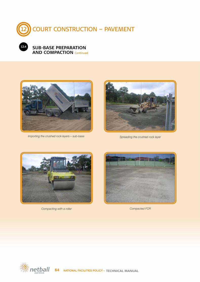
Importing the crushed rock layers – sub-base
Compacted FCR
Spreading the crushed rock layer
12
COURT CONSTRUCTION – PAVEMENT
12.4 SUB-BASE PREPARATION
AND COMPACTION Continued
Compacting with a roller
TECHNICAL MANUALNATIONAL FACILITIES POLICY -64

12
COURT CONSTRUCTION – PAVEMENT
12.5 DRAINAGE
NOTE: Good drainage is one of the most crucial elements in court construction for both asphalt and concrete pavements but unfortunately it is often over looked. Do not make this mistake.
The lack of efficient drainage systems often leads to premature pavement failures, this can be evident within a short period of time after construction! The addition of good drainage infrastructure is a very good investment into the longevity of your netball court.
Considering three main drainage design elements when designing a court is recommended:
Good court surface drainage
Good drainage surrounding the pavement
Good sub surface drainage surrounding the pavement.
12.5.1 GOOD COURT
SURFACE DRAINAGEOutdoor netball courts should have the recommended fall of 1:100 which is 1%. This can either be (a) 1% fall in both directions (which gives you 1.4% or 1:70 fall diagonally) or (b) 1% diagonally on a single plane (which gives you .7% on all sides. This was introduced many years ago to achieve a good balance between efficient court drainage and court playability. The courts should fall to a formed drainage system. This is usually provided by the installation of concrete spoon drains along the lower outer perimeter boundaries of the court pavement. The spoon drains should fall to a large grated inlet pit where the stormwater is collected and directed well away from the pavement areas.
Surface water should not be allowed to drain across more than two courts as it will delay the drying time and will affect play on the lower courts. To alleviate this problem the courts can fall 1% diagonally and have spoon drains and pits installed so that stormwater does not empty over more than two courts before being collected. It is important to note that drainage infrastructure such as this cannot be positioned within the required 3050mm clear run-off zones surrounding each court, therefore additional pavement space will be required to accommodate this drainage infrastructure.
To Clarify: If drainage infrastructure like spoondrains or pits are placed between courts then the 3650mm between court run-off zone standard becomes irrelevant. Instead, a minimum 3050mm will be required between each courts sideline and the spoodrain or pit edge (whichever is closest). Therefore if an average 600mm spoondrain runs between two courts 6700mm minimum will be required. This will add cost to the overall project due to the increase in pavement area but will offer superior play & drainage outcomes.
12.5.2 GOOD DRAINAGE
SURROUNDING THE PAVEMENTThe areas surrounding the pavement should also be shaped so that water is directed away from the pavement areas. Adequate drainage to the pavement surrounds can be achieved in a number of ways:
The court platform should be higher at the lowest point than the surrounding land, if possible. This will minimise the possibility of ground water ponding and seeping under the courts
The platform and the surrounding area should be shaped so that storm water can be directed away from the pavement areas
Earthen swales can be cut in around the pavement to capture water and prevent it from emptying onto the pavement areas.
12.5.3 GOOD SUB-SURFACE
DRAINAGE SURROUNDING THE PAVEMENT
Moisture variations within the subgrade, which is where the subgrade is saturated and then dries out or vice versa, often leads to base cracking, heaving and lifting, and base collapse.This can also cause certain areas of an acrylic surface to delaminate, create new cracks and cause existing cracks to enlarge and widen. As a result, this allows more moisture to enter the pavement, sub-base and subgrade which can lead to further pavement damage and rapid deterioration of the court.
Ideally the subgrade underneath the pavement should remain at a constant moisture level, without dramatic moisture variations. This can be achieved by preventing water ingress under the pavement.
Surface and subsurface drainage systems work hand in hand, one should not be without the other.
Sub surface drains can be placed around the pavement perimeter by installing slotted agi drains approx. 500-700mm below the pavement level – this will depend upon the depth of the pavement and crushed rock design and will be nominated by the civil engineer. There should be inspection shafts placed periodically around the agi drain to assist with maintenance and performance inspections. Agi drains should be fitted with a geotextile sock and be connected into all adjacent pits to ensure efficient drainage away from the pavement areas.
NATIONAL FACILITIES POLICY - 65TECHNICAL MANUAL
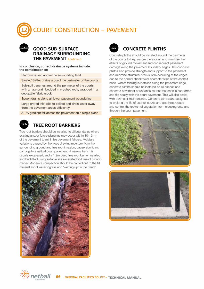
12
COURT CONSTRUCTION – PAVEMENT
12.5.3 GOOD SUB-SURFACE
DRAINAGE SURROUNDING THE PAVEMENT Continued
In conclusion, correct drainage systems include the combination of:
Platform raised above the surrounding land
Swale / Batter drains around the perimeter of the courts
Sub-soil trenches around the perimeter of the courts with an agi-drain bedded in crushed rock, wrapped in a geotextile fabric (sock)
Spoon drains along all lower pavement boundaries
Large grated inlet pits to collect and drain water away from the pavement areas efficiently
A 1% gradient fall across the pavement on a single plane
12.6 TREE ROOT BARRIERS
Tree root barriers should be installed to all boundaries where existing and/or future plantings may occur within 10-15m+ of the pavement to minimise pavement failures. Moisture variations caused by the trees drawing moisture from the surrounding ground and tree root invasion, cause significant damage to a netball court pavement. A narrow trench is usually excavated, and a 1.2m deep tree root barrier installed and backfilled using suitable site excavated soil free of organic matter. Moderate compaction should be carried out to the fill material avoid water ingress and ‘wetting up’ in the trench.
12.7 CONCRETE PLINTHS
Concrete plinths should be installed around the perimeter of the courts to help secure the asphalt and minimise the effects of ground movement and consequent pavement damage along the pavement boundary edges. The concrete plinths also provide strength and support to the pavement and minimise structural cracks from occurring at the edges due to the normal shrink/swell characteristics of the asphalt base. Where fencing is installed along the pavement edge, concrete plinths should be installed on all asphalt and concrete pavement boundaries so that the fence is supported and fits neatly with the court pavement. This will also assist with perimeter maintenance. Concrete plinths are designed to prolong the life of asphalt courts and also help reduce and control the growth of vegetation from creeping onto and through the court pavement.
TECHNICAL MANUALNATIONAL FACILITIES POLICY -66
13
COURT CONSTRUCTION – COURT BASE
13.1 FACTORS TO CONSIDER WHEN
DECIDING WHETHER TO USE CONCRETE OR ASPHALT BASE
There are four main factors to consider when deciding on the court base:
Soil type
Initial construction cost
Ongoing repairs required
Cost of total reconstruction or major rehabilitation at the 40-50 year mark.
It is important to consider the longevity of both pavement types, as poor resistance to the elements and the need for frequent repairs can make any pavement costlier in the long run.
It is very important that you carry out geotechnical testing of the proposed construction site and seek advice, recommendation and design drawings from a civil engineer to detail the type of base is required. An asphalt base may not even be an option. Reactive soil types or siting in a flood prone area is likely to require a concrete base if a long term outcome is desirable. Asphalt pavements are likely to fail rapidly in these conditions.
The following lists are provided to ease the confusion surrounding pavement bases. It is important to note that concrete bases can be chosen even if the soil test and site conditions indicate that an asphalt base would suffice but not vice versa.
Concrete pros and cons include:
• The initial outlay for a concrete pavement is approx. 30-35% more than asphalt. However, the long term repair costs are minimal in comparison to asphalt
• The expected lifespan can be 50yrs to a lifetime if the subgrade and crushed rock base course layers are constructed well and the concrete depth is adequate and installed well, with adequate and constant fall gradients
• Good court drainage and surrounding ground drainage is paramount and root barriers must be installed if there are trees near the pavement area
• Concrete pavements are more resistant to high temperatures and will not become soft like an asphalt pavement. However, if not constructed well they can be susceptible to frost heaving
• Concrete cannot be played on without an acrylic surface due to slipperiness. Concrete bases need to be resurfaced with an acrylic every 7-10 years depending on the degree of use and maintenance. This will be a concrete bases major ongoing costs plus minor repairs, at the time of resurfacing
• A plastic membrane is required under the concrete slab to prevent water ingress through the slab and delamination of the acrylic surface.
Note: Construction Joints and saw cuts are required to minimise random cracking of the concrete and they allow for movement. The Construction Joints (CJ) open and close as the weather conditions/ground conditions change. These CJ’s should be placed outside of the Principle Playing Areas (PPA) usually within or outside the run-off zones.
Asphalt pros and cons include:
• The initial outlay for an asphalt pavement is approx. 30-35% less than concrete. However, the long term repair cost is greater over time as it is not as durable as a well-built concrete base
• Usual lifespan is 20-30 years if the subgrade and crushed rock base course layers and asphalt layer are constructed well and the pavement and surrounding areas are maintained. If it is not constructed well this can be shortened dramatically to 3-5 years, or even less, leading to costly repairs or total reconstruction
• Good asphalt pavement support is very important. Concrete plinths and spoon drains installed around the entire perimeter of the pavement to ‘hold’ the pavement together is important. Court drainage and surrounding ground drainage is paramount and root barriers must be installed if there are trees near the pavement area
• Asphalt courts are more adapted to colder climates, because constant exposure to high temperatures tends to make asphalt soft. In such circumstances, cracks and grooves may appear on the court, necessitating increased repairs
• Asphalt is petroleum based. It is very elastic at the time of installation. Over time, the oils are oxidized and lose their moisture. The colour of the asphalt lightens to grey, and the structure becomes more brittle, making it prone to cracking. Sealing the Asphalt with an acrylic can help
• A good asphalt pavement doesn’t need a surface treatment to enable play, however, expect a lesser lifespan if it isn’t surfaced, as the asphalt does deteriorate faster without the protection of a surface material
• If surfacing with an acrylic then these costs will need to be considered also. Expect the pavement to require resurfacing with an acrylic every 7-10 years, depending on degree of use and maintenance
• Asphalt will most likely develop some form of cracking or pavement damage over its life even if constructed well. Any cracks or signs of pavement damage should be repaired immediately to prevent further deterioration as water penetrates and undermines the pavements subgrade and sub-base material. Periodic repairs are a worthwhile ongoing investment for an asphalt pavement.
The main advantage of asphalt is the low installation cost. If you consider durability and maintenance costs, concrete pavements can be the economical choice in the long run if designed and installed using best industry practice
NATIONAL FACILITIES POLICY - 67TECHNICAL MANUAL

13
COURT CONSTRUCTION – COURT BASE
13.2 ASPHALT BASE – ALSO KNOWN AS:
ASPHALTIC CONCRETE (AC), HOT MIX, TARMAC
Standard asphalt is a mix of Bitumen, Sand & Aggregate.An asphalt base used for netball courts usually has a 5-6mm or 7mm aggregate compared to the asphalt used for roads which contain the larger 10mm or 14mm aggregate.
An asphalt road is continually trafficked by heavy vehicles which continually binds the asphalt together. A netball court however, is not trafficked by vehicles and therefore has a tendency become brittle and weaken over time.
7mm Type L consolidated asphalt to a depth of approx. 30mm, provides a firm and tight surface that binds well for light trafficked asphalt sports pavements. It is important that a Civil Engineer stipulates the type and depth of asphalt pavement required for each project and if a certain standard is required ie: Council standard drawing, traffic authority standard.
If the asphalt is to be coated with an acrylic sports surface it is especially important that the aggregate material in the asphalt mix is free from Ferrous materials such as mineral Pyrites and Marcasite. It should also be free of wood particles, clay or other deleterious materials which may cause staining/discoloration or interfere with the planarity, structural stability or aesthetics of the netball court and/or an acrylic sports playing surface installation and expected lifespan. See Section 13.4.8 ‘Rust Stains / Pyrites’ in this manual for more information.
Asphalt can be porous or non-porous. Porous asphalt or Popcorn asphalt (vernacular) has no sand and can be found in many European countries however in Australia the more typical construction methodology uses a non-porous asphalt for netball court construction.
There are two main elements that make up an asphalt base. The first is the structural layer also known as the “sub-base”, “granular layer” or “fine crushed rock (FCR) layer” which consists of compacted layer(s) of FCR. The thickness of this structural layer(s), the class of fine crushed rock used and the number of layers required is best determined by a Civil Engineer. This will be largely based on a review of the geotechnical report (soil test) findings. (The layer(s) should be spread and compacted in maximum 150mm depth layers). See Section 12.4 ‘Sub-Base Preparation and Compaction’ in this manual for further information. Once the FCR has been spread out and compacted in layers to achieve the right density and tested, as per the engineer’s drawings and specification, a bituminous or polymer material will be sprayed over the granular layer as a “prime coat” also known as “asphalt primer”. This will be allowed to cure before the asphalt is installed. The purpose of the prime coat is to bind the compacted material in the granular layer to preserve its integrity, stabilise moisture levels and to provide the essential bond for the asphalt.
The unsatisfactory alternative to the prime coat is known as a “tack coat”. This cheaper method is not recommended as it has less FCR binding and sealing properties.
This is then covered with a layer of hot mix asphalt, usually at about 30mm minimum thickness. Depth to be determined by the Civil Engineer.
A paving machine is used to install the asphalt pavement. The asphalt is laid in strips, usually 2.74m or 3.66m wide depending on the type of paving machine used.
The operator should take great care to ensure the joins are essentially negligible whilst the machine controls the plane tolerance of the finished surface.
The machine paver uses bitumen with a high melting point of 180°C. In Australia the temperature during the laying and compacting process can vary between 100°C to 160°C.
The finished asphalt is rolled continuously until it achieves a “close and dense” finish. Particular attention to the seams between the asphalt runs is required. These should be flat and as seamless as possible. These joins if not installed and compacted sufficiently can become weak and open over time.
The asphalt layer must be compacted to industry standards of minimum 95% density, or as per the civil engineers instructions.
The asphalt layer provides a sound and smooth surface for playing as well as a moisture barrier to protect the sub-base (FCR layers) from erosion and water ingress.
A concrete plinth/edge beam and/or concrete spoondrains should be installed around the perimeter of the sub-base and asphalt base layers, these should be set accurately to the height of the finished asphalt surface. In addition to providing a strong and stable edge to the court, the concrete edge allows the asphalt to be compacted right up to the edge without the edge collapsing or flaking. The installation of concrete spoondrains will also allow efficient catchment and movement of stormwater away from the pavement area. Insufficient drainage infrastructure or pavement support can result in premature pavement failures. See Section 12.7 ‘Concrete Plinths’ and Section 13.1 ‘Factors to consider when deciding whether to use concrete or asphalt base’ in this manual for more information.
TECHNICAL MANUALNATIONAL FACILITIES POLICY -68

13
COURT CONSTRUCTION – COURT BASE
13.2 ASPHALT BASE – ALSO KNOWN AS:
ASPHALTIC CONCRETE (AC), HOT MIX, TARMAC Continued
Prime coat on the FCR
Asphalt laid in runs
Surveyed and marked
Asphalt paving machine
NATIONAL FACILITIES POLICY - 69TECHNICAL MANUAL

13
COURT CONSTRUCTION – COURT BASE
13.3 CONCRETE BASE – ALSO KNOWN AS:
REINFORCED CONCRETE (RC)
Standard concrete is a mix of Aggregate, sand, cement and water.Concrete is the more substantial base when compared to asphalt, particularly when the geotechnical investigations indicate that the existing sub grade condition is expansive, has a reactive soil type, is made up of uncontrolled fill or is in a flood prone area. The concrete base can be designed to suit once the soil report has identified the severity of the sub grade issues, a standard concrete slab may not perform well in severe conditions.
The concrete required for a netball court is likely to have a recommended strength of 25MPa, 32mpa or 35mpa (depending on the civil engineers advice) with a slump specification of 80%. The concrete is made to various strengths according to the particulars of the job and this should be specified by the civil engineer. The strength is measured in ’MPa’ (Mega Pascals) and is delivered to site ready for installation.
Concrete slabs have a high compression strength and withstand heavy loads without crumbling, unfortunately it has a low tensile strength, and therefore, it will crack easily. The tensile strength in concrete is raised by the use of reinforcing mesh.
The most common concrete base is between 100-150mm depth reinforced concrete base (must be advised by a civil engineer). When the subgrade is of poor quality then a post tensioned concrete base or a waffle pod design may be considered.
Post tensioned or waffle pods are designed to float on top of the subgrade without causing structural cracks. Although significantly dearer, these can outlast any conventional concrete slabs making them an attractive investment.
A standard concrete base will usually consist of; a sub-base with compacted layer(s) of FCR. The thickness of this structural layer(s), the class of fine crushed rock used and the number of layers required is best determined by a Civil Engineer. This will be largely based on a review of the geotechnical report (soil test) findings (the FCR layer(s) should be spread and compacted in maximum 150mm depth layers).’ See Section 12.4 ‘Sub-Base Preparation and Compaction’ in this manual for further information. The FCR is then covered with a moisture barrier consisting of a layer of plastic overlapped and taped. This plastic will stop water being drawn up through the concrete from the subgrade and sub-base layers and prevent delamination of the acrylic sports surface. There is a reinforcing mesh (reo) installed in large sheets across the entire pavement area. The reo is installed on bar chairs set at a height to allow an approx. 40mm cover of concrete over the mesh. The strength of the mesh required is determined by the engineer. Normally an SL82 mesh is
used for a standard court but this can increase to an SL92 or even a SL102 for slabs on problematic sites with reactive soil types. SL stands for “Size & Length” this first number relates to the thickness of the steel and the last number relates to the size of the squares. For example SL92 mesh has 9mm thick steel and 200mm squares/centres.
The concrete should be installed with construction joints and numerous saw cuts to minimise and/or control cracking. In saying this, construction joints positioned through the Principle Playing Area of a netball court should be avoided. If possible, aim to install construction joints in the run-off areas between courts.
NOTE: Most concrete slabs will suffer from shrinkage cracks. These are normally referred to as ‘superficial surface cracks’ or ‘hairline cracks’ and should not cause any ‘structural issues’. The biggest issue with these types of cracks is usually the aesthetics. The reinforcement mesh within the slab should prevent the pavement from shifting vertically. The cracks should remain flat and not cause a trip hazard. Like the asphalt base option, all cracks should be sealed and/or repaired quickly to avoid further deterioration or issues. See Section 13.4.6 ‘Surface and Base Cracks’ in this manual for further information.
All sub-base and prep works must be completed according to the Engineers advice and detailed design and approved by the Project Manager before the formwork (boxing), plastic membrane and reinforcing mesh is set up. The boxing is usually set to the finished slab height. The timber formwork should be straight without dips or warping.
The steel mesh sheets are normally overlapped by one square and securely tied with wire. The mesh is to be fully suspended by being evenly seated on bar chairs at the nominal design height.
TECHNICAL MANUALNATIONAL FACILITIES POLICY -70

13
COURT CONSTRUCTION – COURT BASE
13.3 CONCRETE BASE – ALSO KNOWN AS:
REINFORCED CONCRETE (RC) Continued
All plastic membrane joins should be overlapped and taped. All holes and joins must be taped to avoid moisture being drawn up through the concrete slab.
The concrete is normally designed and ordered as a slump of 80% and is usually delivered in batches of 6m3. A crew of 6 - 10 people is considered necessary depending on the size of the court/s to adequately finish the concrete and achieve the standard tolerances required.
The crew is broken into groups where some are spreading the concrete, some setting the levels with the aid of laser levels and others screeding.
Finally workers will be assigned to “Bull Floats” and “Helicopters” to achieve the necessary surface tolerances.
The finished surface tolerance for concrete is +/-3mm under a 3 meter straight edge when measured in any direction on the court.
NATIONAL FACILITIES POLICY - 71TECHNICAL MANUAL

13
COURT CONSTRUCTION – COURT BASE
13.3.1 SAW CUTS
Saw cuts should be installed to a concrete slab to minimise random cracking and encourage cracks along a set alignment and therefore appear more aesthetically pleasing. Please note that random hairline/shrinkage cracks can still occur and will reflect through a basic acrylic sports surface. The only way to completely eliminate these cracks from being visible is to install a cushioned acrylic sports surface to the concrete slab. See Section 9.12 ‘Court Surface’ and 14.2 ‘Cushioned Acrylic Installation’ in this manual for further information.
Saw cuts are usually 25mm deep and are best installed while the concrete is still ‘soft’ – usually 7am the day after the concrete was poured (depending on temperature and weather conditions). Saw cutting mature concrete slabs is generally a waste of time and money.
The saw blade must be sharp and not tear or chip the concrete at either side of the cut. The saw cuts are usually placed in line with every adjacent fence post (approx. 3m spacing’s if there is no fence). The contractor must take care to continue the saw cut or trowel cut to the fence post and/or light towers. A relief joint or trowel cut should also extend from the fence or light tower posts to the outer edge of any spoon drains or plinths.
13.3.2 SHRINKAGE CRACKS
Shrinkage or commonly known as hairline cracks, appear during the first days or weeks of the curing process. During this time, shrinkage occurs and the concrete strength increases. Shrinkage cracks will appear and is quite common. It is important to note that the strength and structure of the finished slab will not be affected by these cracks. Shrinkage cracks should sit flat and not cause a trip hazard. The main negative of shrinkage cracks is the aesthetics, as they will be noticeable through a non-cushioned (basic) acrylic surface.
13.3.3 EXPANSION JOINTS
Expansion or construction joint/s (CJ) should be installed depending on the size of the court or playing area and soil type.
The purpose of the joint is to divide the courts and/or slabs and allow each section to expand and contract without generating potentially damaging forces within the slab itself or to the surrounding structures.
Expansion/Construction joints are usually a complete ‘gap’ between adjacent slabs, i.e.: there is a definite break between the concrete and reinforcing steel sections. Where adjacent slabs are ‘tied’ together by dowel bars, these dowels are sleeved in one of the slabs to allow expansion and movement to take place without generating stresses within the concrete slabs.
There are a variety of expansion/construction joints available and they can vary in cost. The civil engineer will determine which joint is suitable for each particular project/site.
13.3.4 PROPRIETARY METAL
FORMERS OR TOBY JOINTSThese are popular and are a quick method as the slab can be laid in one pour.
13.3.5 CRACKER JOINTS
These joints are designed to be hammered into the centre of the court to force a crack through the slab, using this method the slab can be laid in one pour too.
13.3.6 DOWEL JOINTS
These are rods that secure the slabs to allow natural movement. With this method, the slab must be laid in two pours while securing the rods to the first half of the slab and greasing the second half prior to the second pour to allow free movement.
13.3.7 LAITANCE
Latency is caused by excessive water in the concrete or by over working the concrete with a helicopter that can cause slurry to rise to the surface. Latency must be removed from the surface before applying any acrylic coatings by using a mix of Hydrochloric or Phosphoric acid diluted with water at a 4:1 ratio, scrubbed with a brush and pressure wash cleaned.
TECHNICAL MANUALNATIONAL FACILITIES POLICY -72

13
COURT CONSTRUCTION – COURT BASE
13.3.8 EFFLORESCENCE
This is the calcium salts that have risen to the surface by water after the concrete has set. An excessive amount of calcium salts rising from the concrete usually indicates poor quality concrete or a high level of trapped subsurface moisture escaping through the surface.
The salts are deposited on either side of cracks in the concrete slab leaving a tell-tale sign of a tram line appearance or a white streak following the fall of the court.
This is a key indicator of none or inadequate sub-surface drainage.
13.3.9 ACCELERATORS
Accelerators are used in concrete to help the concrete cure at a quicker rate. This is a practice done in colder environments when the temperature won’t allow the concrete to cure naturally.
Curing membranes are used to hold the moisture in the concrete longer which allows for the hydration of the cement, the result being a much stronger/harder slab. However, wax and hydrocarbon type membranes remain on the surface and inhibit adhesion of the subsequent acrylic coatings. These need to be totally removed adding extra cost to the project.
There are specially developed sealing products that are applied to the concrete slab after it is installed. These are designed to seal the concrete to allow surfacing with an acrylic sports surface earlier than the recommended 28 day curing period. This can enable a reduced project timeframe and where timeframes are tight it can mean the difference between surfacing the pavement prior to the cold and wet weather season or delaying the project many months until more favourable weather conditions return.
Note: All concrete accelerator and sealing products should be researched well and the advantages and disadvantages considered before installation. Ensure the same acrylic surface related warranties apply to the concrete slab and surfacing components of the project with and without the use of the sealing product.
13.4 COMMON BASE ISSUES
13.4.1 BASE ISSUES INTRODUCTION
There are many netball facilities across Australia where the courts have failed. This can be due to a number of reasons, such as:
Inadequate site investigations and engineering advice
Inadequate detailed design and specification
Insufficient budget for the works required
Poor selection of the principle contractor and/or the sub-contractors
Poor workmanship and attention to detail during the construction period
Inadequate contractor supervision/project management
Deterioration failures including flood, tree root damage and/or poor drainage issues
Poor selection of construction materials.
Advice should always be sought from the experts in the relevant industry as noted in Section 4 of this Technical Manual.
NOTE: There are no shortcuts in building a quality sports pavement. Any short cuts taken during the planning, design and construction periods will result in more expensive pavement repairs or even total replacement.
It is much better to follow the recommended process outlined in this manual than dealing with disgruntled stakeholders and possible financial implications as a result of a failed netball court pavement.
NOTE: It is important to note that most land allocated for recreational purposes is leftover land not suitable for the construction of buildings or houses.
NATIONAL FACILITIES POLICY - 73TECHNICAL MANUAL

13
COURT CONSTRUCTION – COURT BASE
13.4.2 CONSTRUCTION FAILURES
Base failures can be caused by one or more of the following during construction:
Insufficient compaction of the subgrade
Failure to thoroughly remove all vegetation and detritus in the sub grade. This is known as “soft spots”. This will cause subsidence creating voids under the granular layer and in time this will collapse leaving a depression and/or cracking on the surface
Insufficient compaction of the granular (fine crushed rock) layer
Incorrect specification of the granular type and depth required in the sub-base layers
Incorrect specification of the concrete base type, depth, and strength
Poor installation of the concrete or asphalt base
Poor application of, or damage to the asphalt primer coat
Insufficient compaction of the asphalt layer
Insufficient time allowed for the asphalt to cool below the threshold before installation. This will cause delaminating and similar problems
Insufficient rolling and treatment of the asphalt cold joints (the join between runs with the paving machine). This will cause cracking over time and allow moisture to penetrate the sub grade.
13.4.3 DETERIORATION FAILURES
Deterioration failures are failures that are caused over time such as:
Inadequate compaction of the subgrade, sub-base & base layers
Excessive moisture changes under and around the pavement
Uncoated asphalt will degenerate much quicker than coated asphalt by the loss of oils and binders from the constant exposure to UV
Tree roots and other vegetation will cause severe cracking resulting in an uneven surface and allowing the penetration of moisture through the damaged areas
Water (flood) inundation
Lack of appropriate surface and surrounding court drainage
Lack of a regular pavement, surface & drainage maintenance program
Deleterious or mineral particles in the courts base material, such as clay or Ferrous particles (also known as Pyrites or Iron particles) in asphalt. This can be especially damaging when asphalt courts are surfaced with an acrylic sports surface - rust stains, blisters and pitting can occur depending on the severity. See Section 13.4.8 ‘Rust Stains / Pyrites’ in this manual for further information.
Note: Construction and deterioration failures are very much preventable. By applying a standard measure of quality from the planning stage through to the construction and maintenance stages of a netball court project, many failures can be avoided.
13.4.4 SUBSIDENCE
Subsidence can be caused by poor compaction of the subgrade and/or sub-base materials. It can also be caused when existing soft spots or deleterious/organic materials such as tree- stumps, roots, grasses, timber and rubbish were not removed during the construction period. All of these materials will eventually decompose, settle and shrink, causing the courts pavement above these decomposing items to also settle over time. This can result in base movement and surface collapse in these weak areas.
TECHNICAL MANUALNATIONAL FACILITIES POLICY -74
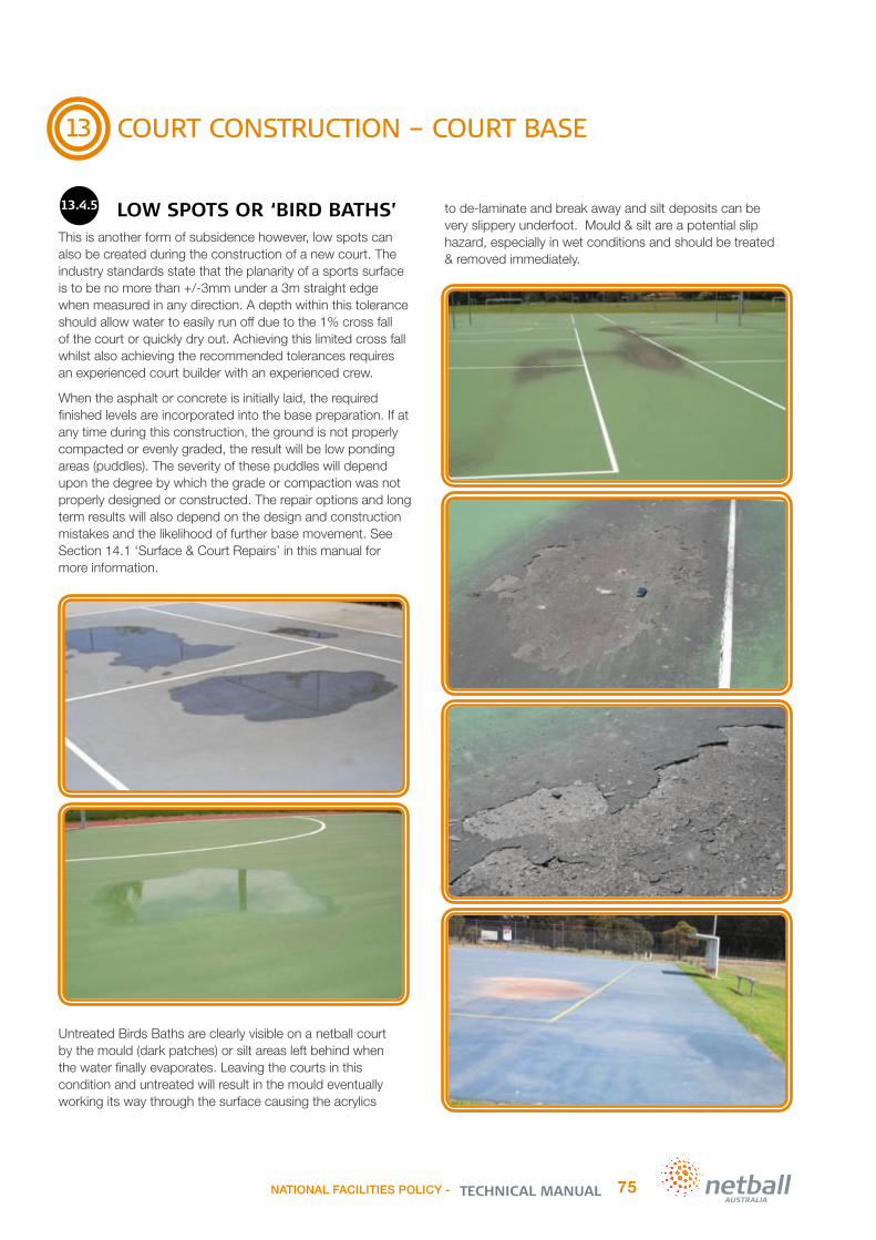
13
COURT CONSTRUCTION – COURT BASE
13.4.5 LOW SPOTS OR ‘BIRD BATHS’
This is another form of subsidence however, low spots can also be created during the construction of a new court. The industry standards state that the planarity of a sports surface is to be no more than +/-3mm under a 3m straight edge when measured in any direction. A depth within this tolerance should allow water to easily run off due to the 1% cross fall of the court or quickly dry out. Achieving this limited cross fall whilst also achieving the recommended tolerances requires an experienced court builder with an experienced crew.
When the asphalt or concrete is initially laid, the required finished levels are incorporated into the base preparation. If at any time during this construction, the ground is not properly compacted or evenly graded, the result will be low ponding areas (puddles). The severity of these puddles will depend upon the degree by which the grade or compaction was not properly designed or constructed. The repair options and long term results will also depend on the design and construction mistakes and the likelihood of further base movement. See Section 14.1 ‘Surface & Court Repairs’ in this manual for more information.
Untreated Birds Baths are clearly visible on a netball court by the mould (dark patches) or silt areas left behind when the water finally evaporates. Leaving the courts in this condition and untreated will result in the mould eventually working its way through the surface causing the acrylics
to de-laminate and break away and silt deposits can be very slippery underfoot. Mould & silt are a potential slip hazard, especially in wet conditions and should be treated & removed immediately.
NATIONAL FACILITIES POLICY - 75TECHNICAL MANUAL
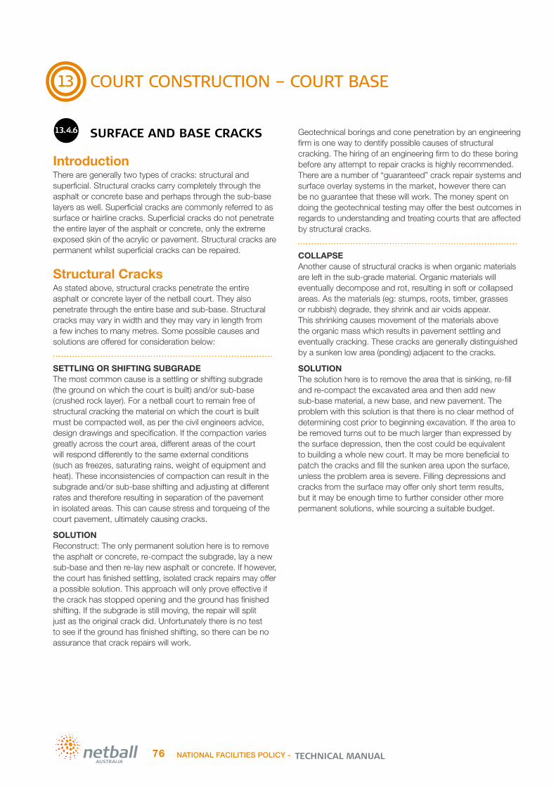
13
COURT CONSTRUCTION – COURT BASE
13.4.6 SURFACE AND BASE CRACKS
IntroductionThere are generally two types of cracks: structural and superficial. Structural cracks carry completely through the asphalt or concrete base and perhaps through the sub-base layers as well. Superficial cracks are commonly referred to as surface or hairline cracks. Superficial cracks do not penetrate the entire layer of the asphalt or concrete, only the extreme exposed skin of the acrylic or pavement. Structural cracks are permanent whilst superficial cracks can be repaired.
Structural CracksAs stated above, structural cracks penetrate the entire asphalt or concrete layer of the netball court. They also penetrate through the entire base and sub-base. Structural cracks may vary in width and they may vary in length from a few inches to many metres. Some possible causes and solutions are offered for consideration below:
SETTLING OR SHIFTING SUBGRADE The most common cause is a settling or shifting subgrade (the ground on which the court is built) and/or sub-base (crushed rock layer). For a netball court to remain free of structural cracking the material on which the court is built must be compacted well, as per the civil engineers advice, design drawings and specification. If the compaction varies greatly across the court area, different areas of the court will respond differently to the same external conditions (such as freezes, saturating rains, weight of equipment and heat). These inconsistencies of compaction can result in the subgrade and/or sub-base shifting and adjusting at different rates and therefore resulting in separation of the pavement in isolated areas. This can cause stress and torqueing of the court pavement, ultimately causing cracks.
SOLUTIONReconstruct: The only permanent solution here is to remove the asphalt or concrete, re-compact the subgrade, lay a new sub-base and then re-lay new asphalt or concrete. If however, the court has finished settling, isolated crack repairs may offer a possible solution. This approach will only prove effective if the crack has stopped opening and the ground has finished shifting. If the subgrade is still moving, the repair will split just as the original crack did. Unfortunately there is no test to see if the ground has finished shifting, so there can be no assurance that crack repairs will work.
Geotechnical borings and cone penetration by an engineering firm is one way to dentify possible causes of structural cracking. The hiring of an engineering firm to do these boring before any attempt to repair cracks is highly recommended. There are a number of “guaranteed” crack repair systems and surface overlay systems in the market, however there can be no guarantee that these will work. The money spent on doing the geotechnical testing may offer the best outcomes in regards to understanding and treating courts that are affected by structural cracks.
COLLAPSE Another cause of structural cracks is when organic materials are left in the sub-grade material. Organic materials will eventually decompose and rot, resulting in soft or collapsed areas. As the materials (eg: stumps, roots, timber, grasses or rubbish) degrade, they shrink and air voids appear. This shrinking causes movement of the materials above the organic mass which results in pavement settling and eventually cracking. These cracks are generally distinguished by a sunken low area (ponding) adjacent to the cracks.
SOLUTIONThe solution here is to remove the area that is sinking, re-fill and re-compact the excavated area and then add new sub-base material, a new base, and new pavement. The problem with this solution is that there is no clear method of determining cost prior to beginning excavation. If the area to be removed turns out to be much larger than expressed by the surface depression, then the cost could be equivalent to building a whole new court. It may be more beneficial to patch the cracks and fill the sunken area upon the surface, unless the problem area is severe. Filling depressions and cracks from the surface may offer only short term results, but it may be enough time to further consider other more permanent solutions, while sourcing a suitable budget.
TECHNICAL MANUALNATIONAL FACILITIES POLICY -76

13
COURT CONSTRUCTION – COURT BASE
13.4.6 SURFACE AND BASE CRACKS
Continued
Structural Cracks Continued
POOR COMPACTION Improper compaction of the sub-grade and/or sub-base layers or poor application of the asphalt or concrete itself can create cracks. Again, the most important and critical area of a netball court is the supporting structural layers under the asphalt or concrete. If this is not of adequate thickness, density, compaction and consistency, then everything laid upon it will be inferior. If the material below the asphalt or concrete base is not solid, then no amount of money or material above the surface will solve the problem. You can’t have movement below asphalt or concrete and not expect to have cracking in the asphalt or concrete. This applies to the acrylic materials also. If the asphalt or concrete is not solid and firm, then the acrylic material laid upon it is likely to also crack.
SOLUTIONReconstruct the affected area of the court. The key is to make sure that construction is monitored and that proof rolling and independent compaction testing is conducted on every pavement layer, including the subgrade, each sub-base (crushed rock) layer and pavement (asphalt or concrete) layer. The civil engineer will have specified the compaction rate required for each layer and this should be strictly adhered to, tested and approved by a project manager before commencing work on the next layer throughout the court construction process.
POOR DRAINAGE & TREE ROOTS The lack of adequate surface and/or perimeter drainage can allow water to infiltrate the subgrade and sub-base material of the pavement. Trees that are in close proximity to the court pavement can result in tree root invasion under and through the pavement. The trees also draw moisture from the ground (subgrade). In both cases, poor drainage and tree root issues, cause the subgrade to expand and contract as it dries out, and conversely, gets saturated. These moisture variations create movement in the subgrade and pavement layers and can result in significant pavement cracking.
SOLUTIONReconstruct the affected area of the court. The key is to make sure the design and court construction includes adequate surface and perimeter drainage design and protection from tree roots.
Drainage: Agi drains installed to the outside perimeter of the entire pavement area to capture and direct subsurface water away from the pavements subgrade is very important. This should include inspection shafts so that their efficient operation is monitored and they should also connect into
the surrounding drainage pits. Ensure adequate fall (1:100) across the pavement is achieved. This should fall to a formed drainage system, with wide concrete spoondrains to all low boundaries of the pavement and at the base of any raised or retained surrounding areas. These spoondrains should empty into large drainage pits to capture surface water and direct it away from the pavement area. It is also beneficial if the surrounding ground falls away from the pavement. Selecting a site that offers good natural drainage and is not flood prone is recommended.
Tree Roots: Tree root barriers should be installed to all boundaries where existing and future planting may occur within 10-15m of the pavement to ensure tree root damage is not an issue now, and in the future. Avoid planting near pavements as moisture variations and tree root invasion in the subgrade both around and under the pavement can cause significant damage to the pavement. If tree removal is required, an arborist report and/or a tree removal permit may be required. It is best to check with your local council or relevant government organisation or land owner. Selecting a site that is clear of large trees and/or problematic vegetation is recommended.
Summary Of Structural Cracks:Structural cracks can be prevented by following best practice construction standards, but they cannot be repaired permanently unless the area affected is removed and then replaced. This process is usually very expensive.It is vitally important that cracks do not create a trip hazard for the intended users. If the crack is heaving or sunken to the point where a player may trip or slide, resulting in a loss of balance, then the area must be repaired. Any deviation that is +/-3mm is considered a trip hazard. If, however, the crack is level and flat with no discernible footing problems then the crack (with the knowledge that it will eventually get worse) is nothing more than an eye sore. It is advisable to repair the crack in the short term, to minimise further deterioration of the pavement caused by water ingress.
The only long term repair of a structural crack is to remove the area affected, compact the subgrade and install new sub-base and base material. Any other method such as patching, or overlaying will not keep the ground from moving and therefore not prevent the re-occurrence of the cracking. Every situation is different, as every crack is different, but generally structural cracks come back. The question is not if, but when.
NATIONAL FACILITIES POLICY - 77TECHNICAL MANUAL
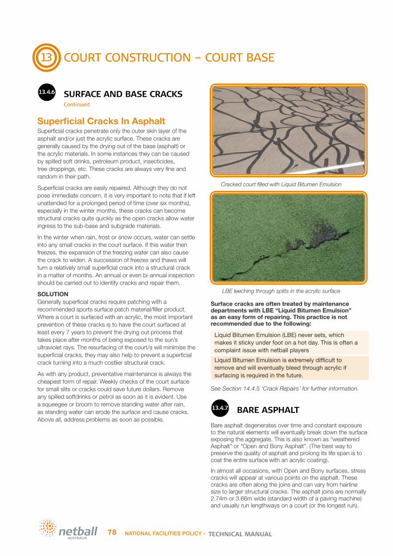
13
COURT CONSTRUCTION – COURT BASE
13.4.6 SURFACE AND BASE CRACKS
Continued
Superficial Cracks In AsphaltSuperficial cracks penetrate only the outer skin layer of the asphalt and/or just the acrylic surface. These cracks are generally caused by the drying out of the base (asphalt) or the acrylic materials. In some instances they can be caused by spilled soft drinks, petroleum product, insecticides, tree droppings, etc. These cracks are always very fine and random in their path.
Superficial cracks are easily repaired. Although they do not pose immediate concern, it is very important to note that if left unattended for a prolonged period of time (over six months), especially in the winter months, these cracks can become structural cracks quite quickly as the open cracks allow water ingress to the sub-base and subgrade materials.
In the winter when rain, frost or snow occurs, water can settle into any small cracks in the court surface. If this water then freezes, the expansion of the freezing water can also cause the crack to widen. A succession of freezes and thaws will turn a relatively small superficial crack into a structural crack in a matter of months. An annual or even bi-annual inspection should be carried out to identify cracks and repair them.
SOLUTIONGenerally superficial cracks require patching with a recommended sports surface patch material/filler product. Where a court is surfaced with an acrylic, the most important prevention of these cracks is to have the court surfaced at least every 7 years to prevent the drying out process that takes place after months of being exposed to the sun’s ultraviolet rays. The resurfacing of the court/s will minimise the superficial cracks, they may also help to prevent a superficial crack turning into a much costlier structural crack.
As with any product, preventative maintenance is always the cheapest form of repair. Weekly checks of the court surface for small slits or cracks could save future dollars. Remove any spilled softdrinks or petrol as soon as it is evident. Use a squeegee or broom to remove standing water after rain, as standing water can erode the surface and cause cracks. Above all, address problems as soon as possible.
Surface cracks are often treated by maintenance departments with LBE “Liquid Bitumen Emulsion” as an easy form of repairing. This practice is not recommended due to the following:
Liquid Bitumen Emulsion (LBE) never sets, which makes it sticky under foot on a hot day. This is often a complaint issue with netball players
Liquid Bitumen Emulsion is extremely difficult to remove and will eventually bleed through acrylic if surfacing is required in the future.
See Section 14.4.5 ‘Crack Repairs’ for further information.
13.4.7 BARE ASPHALT
Bare asphalt degenerates over time and constant exposure to the natural elements will eventually break down the surface exposing the aggregate. This is also known as “weathered Asphalt” or “Open and Bony Asphalt”. (The best way to preserve the quality of asphalt and prolong its life span is to coat the entire surface with an acrylic coating).
In almost all occasions, with Open and Bony surfaces, stress cracks will appear at various points on the asphalt. These cracks are often along the joins and can vary from hairline size to larger structural cracks. The asphalt joins are normally 2.74m or 3.66m wide (standard width of a paving machine) and usually run lengthways on a court (or the longest run).
LBE leeching through splits in the acrylic surface
TECHNICAL MANUALNATIONAL FACILITIES POLICY -78
Cracked court filled with Liquid Bitumen Emulsion

13
COURT CONSTRUCTION – COURT BASE
13.4.7 BARE ASPHALT Continued
The asphalt is laid in strips and when they lay the adjoining run, the temperature often differs between the freshly laid asphalt and the previously laid asphalt. This is called a “Cold joint” and this may split or crack along the join over time. This is also known as a Construction failure.
Random cracking throughout the courts can be due to a variety of reasons such as sub-base movement, moisture and/or poor compaction. When you have random ‘bird baths’ in addition to the cracks, this indicates poor base preparation and subsequent pavement collapse. ‘Bird baths’ are easily located on a court by the collection of dirt and/or silt left behind once all the moisture has evaporated.
13.4.8 RUST STAINS/PYRITES
A secondary mineral such as ferrous particles (Pyrites) can be present in the asphalt mix of an asphalt base netball court.Asphalt containing these ferrous particles should be avoided especially when the court is to be surfaced with an acrylic sports surface.
This is naturally occurring in aggregates from certain geographical locations and can cause unsightly brown stains, blisters and pitting to appear on new acrylic surfaces.
This is seen too often in many areas of Australia. Caused by Pyrite (iron particle) in aggregates used in the manufacture
of the asphalt mix. As rain falls on the courts the moisture permeates through the acrylic colour surface system which moistens the aggregate in the asphalt layer. If pyrites are present, the oxidation (rust) process is initiated and with time the particles migrate to the court surface and become evident by a rust colour observed above theseaggregate particles. These rust spots and streaks can create merely an aesthetic issue or they can be capable of causing localised surface & pavement failures when they swell and blister as it oxidises and subsequently pops through the surface. It can take approx. six (6) to twelve (12) months after the courts are completed for the rust stains to appear and ultimately rust streaks form in the direction of the slope of the netball court. They can continue to increase in number over the following twelve (12) months or more.
TreatmentSome courts can be severely affected and unfortunately once Pyrites are in the asphalt base, not much can be done to prevent their effect on an acrylic surface.
Raised and/or blistered spots and pitting of differing severity can expose the asphalt to water ingress and increased pavement deterioration if left untreated. The remedial works required will depend upon the severity and quantity of the rust spots and pavement damage. Blisters may be ground down, patched or sealed and then resurfaced or in minor cases dug out and patched/sealed and then resurfaced. In saying this, it is very important to note that this is not guaranteed to stop the problem from recurring.
Some acrylic surface manufacturers have special sealers such as an Epoxy Moisture Seal available which may minimise the recurrence of the rust stains however this adds cost and is not guaranteed to stop the reappearance of the stains. When resurfacing affected areas it is a good idea to pick acrylic colours that closely match and don’t contrast the rust colour (i.e.: Brown, Maroon, and Red) to minimise the appearance of any new stains.
NATIONAL FACILITIES POLICY - 79TECHNICAL MANUAL

14
COURT CONSTRUCTION – COURT SURFACE
13.4.8 RUST STAINS/PYRITES Continued
PreventionDue to the lack of a known guaranteed permanent solution for courts affected by the appearance of rust, blisters and pitting on an acrylic surfaced asphalt pavement that already contains Pyrites, it is clear that prevention is the best mitigation strategy. Perhaps highlighting the potential issue to the proposed contractor/asphalt company may in turn result in assurances from the proposed asphalt plant or at least promote a discussion regarding the type and source of the asphalt proposed. It may be of great benefit to ensure the project brief, request for quote or project specification clearly articulates the need for a Pyrite free asphalt to the contractor. Something to the effect of “The aggregates used in the mix shall be free from mineral pyrites, marcasite, wood particles, clay or other deleterious materials which may cause staining/discoloration or interfere with the planarity, structural stability or aesthetics of an acrylic sports playing surface.”
Properly informed contractors/asphalt producers who, through the course of time, have been shown to supply aggregate in their asphalt that fails to meet this specification should be held accountable and avoided for future netball court construction projects where an acrylic surface is required.
Some asphalt producers may not otherwise be attuned to such issues because they provide asphalt pavement primarily for roadways and carparks where the presence of Pyrites is not as obvious. In contrast, if the asphalt contains Pyrites and is used in an asphalt base surfaced with an acrylic sports surface, it will be noticed by many due to the acrylics coloured surface.
Given that Pyrites occur in natural geologic deposits in the earth. Pyrites are most commonly found in crushed stone and are not discernible in an aggregate pile by observation. Although there are tests for determining the presence of pyrites in aggregates, the difficulty is finding a representative sample of the crushed aggregate that contains pyrite. The ferrous bearing particle could be one-in-one thousand or more particles – making it extremely difficult to detect by random testing of aggregate samples. Fortunately, ferrous bearing aggregate is well-known by geographical source and each asphalt producer should be aware of the presence of aggregate contaminants based upon each source as well as documented by local historical evidence.
Summary of Tips:
Avoid the use of recycled asphalt.
Avoid any asphalt source that is known to contain Pyrites or other Ferrous bearing aggregate.
Research the type and source of the asphalt and aggregate proposed for your project.
Talk to an experienced court builder, nearby acrylic surfaced netball facility owners & local councils.
If in doubt use dark acrylic colours or colours similar to the colour of rust when surfacing your courts.’
13.4.9 CONCLUSION
It is essential to have a good understanding of a netball court pavements design & construction elements. It is very important to adopt industry best design and construction principles to not only avoid the above common failures but to successfully address them if they do occur. Soil tests, sufficient excavation depth, preparation and compaction of the subgrade and sub-base, root barrier and drainage works are very important components of a netball court construction. Unfortunately these important components are ignored too often, downgraded, or simply left out due to insufficient budgets. Cutting costs during the construction and remedial repair stages are likely to add many more dollars to the pavements lifecycle costs and/or reduce the predicted pavements lifespan.
14.1 ACRYLIC SURFACE APPLICATION
14.1.1 APPLICATION ON ASPHALT
– NON-CUSHIONED ACRYLICA new asphalt surface should be left to cure for at least 2 weeks, and preferably four weeks before applying an acrylic surface. UV light from the sun as well as rain or other water will assist in the curing period. If surfacing is attempted while the asphalt is still volatile, splitting may occur through the acrylic coatings.
Before commencing surfacing, the asphalt should be water blasted clean and flooded or inspected shortly after rain to identify any ponding areas. Allow the court to drain for a period of half an hour at a temperature of around 21°C or for a shorter period if the weather is hotter. Any low areas or ‘bird baths’ holding water greater in depth than 2-3mm [this can be measured using a 20 cent coin] should be clearly marked to be patched out with filling compounds prior to surfacing.
Additionally, carefully check the asphalt for small blisters while the court is wet. Blisters could indicate some foreign materials are present in the asphalt. Small blisters containing these materials can be remedied by water blasting. Larger blisters or bumps may have to be dug out and repaired with fillers. Asphalt containing ferrous particles (iron) such as Pyrites can cause damage to an asphalt base netball court surfaced with an acrylic sports surface. It is best to avoid asphalt mixes that contain these particles. See Section 13.4.8 ‘Rust Stains / Pyrites’ in this manual for further information.
TECHNICAL MANUALNATIONAL FACILITIES POLICY -80

14
COURT CONSTRUCTION – COURT SURFACE
14.1.1 APPLICATION ON ASPHALT
– NON-CUSHIONED ACRYLIC Continued
Carefully check the area where the asphalt run joins the next asphalt pass. These areas are ‘bony’ and the asphalt is less dense. Ideally these should be filled and re-compacted during the asphalt installation. However if this does not occur, then these areas should be compacted by hand, and then filled to the correct profile prior to surfacing. Always use fillers as recommended by the acrylic manufacturer. If ingrained mud is present it will be necessary to water blast these areas clean. All patching and filling work should be carried out utilising the manufacturer’s recommended products and specifications. Using alternative products may void the guarantees provided by the manufacturer/applicator.On completion of patching and filling, all repair work must be sanded down or ground to produce a smooth even surface, with relatively uniform texture. The surface should then be thoroughly cleaned using a heavy duty blower to present a spotlessly clean area ready for the acrylic coatings.Filled and patched areas should be inspected, and a preliminary coating of the base coat applied to these areas, if required, to obtain the desired texture.The base coat usually consists of an acrylic binder and a heavier grading of silica sand, so that small voids and variations of texture in the asphalt is masked. This coat is applied to the entire court area [fence to fence].When the base coat is thoroughly dry, inspect for ridges and ‘up-jumps’ [squeegee marks], and scrape or grind smooth before proceeding with the topcoats.Normally one or two base coats and approx. two topcoats are applied to a new asphalt surface, depending on the quality of the asphalt. No coating work should be contemplated if rain is imminent.Additionally, the air temperature should be a minimum of 12° and rising. Coating will become difficult once the temperature passes 30°. Most experienced applicators will use an infra-red thermometer to measure surface temperature, and will only apply material in the surface temperature range of 12° minimum to 35° maximum surface temperature.All acrylic coatings are applied with a rubber squeegee. Sometimes a fine hair broom immediately follows the squeegee pass. If the surface is level, a well trained and experienced squeegee operator should not require a following broom pass. However, on uneven surfaces such as old asphalt or concrete, a squeegee finish can result in ‘bald’ patches on high spots, and following the squeegee with a broom can eliminate this. A broomed finish is often better for surfaces such as netball where extra grip is required.There are differing theories regarding the application of acrylics. Some manufacturers and contractors recommend that the topcoats be applied in an alternate direction to the base coat. Others say all coats should be applied in the same direction. Most experienced contractors tend to squeegee across the court, particularly on warmer days, as the shorter pass enables achievement of a more evenly textured surface.
On hot days the materials will tend to ‘chaff up’ and become unworkable. This tends to support the theory that the coatings be applied across the court for the playing area, and to utilise the shortest distance possible when applying the surrounds. In any event, the coatings should be applied evenly and to a uniform thickness over the entire court area. This will require an experienced applicator, and care should be taken in choosing the contractor.
14.1.2 APPLICATION ON CONCRETE
A new concrete slab must be allowed to cure for a minimum of four weeks (28 days minimum) before any surfacing is contemplated. The longer it is allowed to cure the better.It is imperative that the concrete itself is spotlessly clean, and no laitance or concrete salts are present on the surface. A simple test is to rub the palm of the hand on the concrete. If a whitish residue is apparent on the palm then surfacing should be delayed until the migration of concrete salts stops.Generally a concrete slab is acid etched, that is treated with hydrochloric acid, using four parts water/one part acid solution, and then water blasted clean prior to any surface application. The surface should be thoroughly dry and clear of all concrete salts. All saw cut residues must be removed during the acid etch and water blasting treatment.As with coating asphalt based courts, all depressions holding water should be patched to correct the profile, utilising materials and methodologies recommended by the manufacturer, and any high spots removed by grinding with a concrete planer. Expansion/construction joints can be filled with an elastomeric polyurethane joint-filler. This however is not essential. To ensure a bond with the surfacing materials, some fine sand should be rubbed into the joint-filler surface prior to the curing process. Do not use acrylic caulking materials for expansion joints.When patching is completed, a prime coat as recommended by the manufacturer should be applied to the entire court.If a two-part epoxy primer is used, it is very important that the manufacturer’s specifications are closely adhered to. The first acrylic coating should be applied while the epoxy primer is still ‘tacky’ to touch. This will ensure a strong bond with the concrete base while still allowing a degree of vapour transmission from the slab.Once the initial coating of acrylic has been applied, it is best to leave the surface overnight. The remaining two top coats can then be applied on the following day, given good drying conditions.Line marking can then be completed in a similar fashion as described previously in Section 9.5 ‘Line Marking’ of this manual.
NATIONAL FACILITIES POLICY - 81TECHNICAL MANUAL

14
COURT CONSTRUCTION – COURT SURFACE
14.1.3 TWO COLOUR APPLICATION
If the court is to be in two colours, with a contrasting colour for the surrounds, the four corners of the playing area should be established and marked with a washable marker. Do not use timber crayon. A chalkline can then be applied to the marked out area.Two topcoats are then applied to the playing area using a squeegee or a broom finish. Each coat should be thoroughly dry before proceeding with the next coat. Drying time will vary according to the ambient temperature and humidity.
Once the playing area is completed it should be accurately taped off using a taping machine, then one to three coats applied to the surrounds in contrasting colours as chosen by the owner. The edges of the court should be finished off neatly with the bottom sections of the fencing posts taped off to prevent the acrylic coating marking the posts. A strip of masking tape around the edge of the court will provide a neat, straight line finish.
It will take some time for the court surface to fully cure. This can vary depending on the weather conditions, so it is best to avoid playing on the court until the acrylic installer has given the all clear. Using the court before the surface has fully cured may result in colour and line distortion and can even result in premature surface wear.
Some important points to be aware of:
• Newly applied colour coatings may have slight variations in the surface. The squeegee blade moving across the court from side to side (or end to end) will cause the textured surface to reflect the sun and light so that it can appear ‘streaky’. This is a somewhat similar effect to that made by large mowers on cricket or football ovals. A finished surface should be inspected for uniform colour and texture at a distance of 8 to 10 metres, with the sun directly above or behind the viewer.
• Some sports shoes will leave scuff marks on a newly surfaced court. This is caused by the sand content in the acrylic materials. It will decrease as the sand becomes polished with play, and should not be of any concern. Black soled shoes (even those claimed to be ‘non-marking’), however, leave very unsightly marks which are almost impossible to remove, and should be banned from use on any acrylic court.
• After the first few rainy spells, soap bubbles may appear on the surface of a newly coated court. Detergents are added to the coating materials to assist with colour dispersion. After several periods of rain the detergents will be washed out, and this will no longer occur. On indoor courts the detergents are not washed out, so if washed or wet, the surface may be slippery for a few weeks, and care should be exercised when initially using the courts.
• If the court is in an area where bird and flying-fox droppings are prevalent, it is best to have a regular inspection and maintenance program. These droppings are acidic, and can eat through the acrylic surface, causing a small piece of the court to lift out. They should be washed off with mild detergent and warm water before damage occurs.
14.1.4 DRYING REQUIREMENTS
It is important for the water in the coating to evaporate out of the mix within three to four hours after application. Water remaining in the film too long could affect uniformity of colour, adhesion, and sand retention. If the temperature is towards the lower threshold, do not apply the acrylic late in the afternoon.
14.1.5 PROCEDURES TO BE AVOIDED
IN APPLYING ACRYLIC COATING MATERIAL
Do not apply coatings unless the surface temperature is 12°C and rising
Do not apply coatings if the surface has been exposed to freezing temperatures the night before; i.e. allow the surface to rise to 12°C
Do not apply material if surface temperature is above 40°C
Do not apply subsequent coat until previous coat is completely dry. The interval between coats is related to the drying conditions. Heat and low humidity accelerate drying
Applying acrylic coatings during the night time hours of darkness is NOT recommended
Do not apply acrylic coatings if the surface is wet
Do not permit excessive material to remain in low spots on the final coat, otherwise these areas will mud-crack and shine
Do not pull material more than 18 metres in hot or windy conditions
Do not play on court surface until the installer has advised that the surface is fit for purpose.
TECHNICAL MANUALNATIONAL FACILITIES POLICY -82

14
COURT CONSTRUCTION – COURT SURFACE
14.2 CUSHION ACRYLIC
INSTALLATION
14.2.1 CUSHION ACRYLIC
BASE PREPARATIONBase tolerance for cushion surfaces is similar to that for basic acrylic (non-cushioned) hardcourts. Planarity is reported by measuring the deviation beneath a 3m straight edge. The target is +/-3mm beneath the 3m straight edge tested in any direction and placed anywhere on the surface. The intention of this tolerance is to ensure that the court drains quickly following showers or storms and that the surface does not produce an uneven surface. The +/-3mm tolerance may be difficult to achieve on some bases such as asphalt, therefore only experienced sports court pavement experts should be engaged.
Asphalt must cure for a minimum of 14 days before installation of the cushion acrylic system. Concrete bases require longer curing times with a minimum 28 days required before application of the cushioned acrylic surface.
Asphalt is cleaned by blasting with a high pressure water cleaner and must be free from all dust, dirt and grease. The surface must be thoroughly dry before application of the cushioned system.
Concrete is acid etched with a hydrochloric acid solution to the manufacturer’s specification. All acid residue is then removed using fresh water under pressure and all dust, dirt and grease must be removed. The concrete must be thoroughly dry before application of the cushion system.
14.2.2 TYPES OF CUSHION
ACRYLIC SURFACESCushion acrylic surfaces fall into two broad groups, “Liquid Applied Cushion” systems (also known as Wet Lay) and “Mat Lay Cushion” systems. They are quite different surfaces in the way they are installed. Costs can also vary significantly depending upon the composition of the system selected (i.e. the number of layers of each material type used). Mat lay systems are further divided by the thickness of the cushion used and design parameters.
Cushion layers are complex technical/chemical systems and should be installed by trained applicators approved by the product manufacturer.
14.2.3 LIQUID APPLIED
CUSHION SYSTEMSInstallation of Liquid Applied Cushion involves the spreading of a liquid rubber compound over the specially constructed asphalt or concrete base, building up in layers until the desired cushion thickness is achieved.
The thickness of the rubber installed determines the cushioning achieved and of course, the cost of the surface.
An advantage of a Liquid Applied system is that the thickness of the cushion can be adjusted to suit the individual projects cushioning or budget requirements. Following installation of the cushion layers, an acrylic surface is then installed over the top. Typically, Liquid Applied systems range from 1mm to 5mm in thickness.
14.2.4 INSTALLATION OF LIQUID
APPLIED CUSHION SYSTEMSThe base is prepared as described above.
Asphalt is firstly treated with an acrylic “resurfacer”, applied using a rubber squeegee. The resurfacer serves two purposes, it provides a primer coating to assist adhesion of the cushion material and fills imperfections and pores in “bony” open surfaces.
Concrete is prepared using different sealers. The concrete sealer is applied using either squeegee or roller and promotes adhesion of the cushion material to the concrete base.
Cushion material is delivered to site in drums and mixed, on site, with potable water in accordance with the manufacturer’s recommendations. The cushion material is then applied in layers, again using a rubber squeegee. Initial layer(s) consist of a coarse material; subsequent layer(s) are a fine material. Cushion material must be allowed to cure between coats.
Ideally, three coats of specially formulated acrylic are applied in a similar fashion to a standard acrylic hardcourt. The court is finally line marked for play.
NATIONAL FACILITIES POLICY - 83TECHNICAL MANUAL

14
COURT CONSTRUCTION – COURT SURFACE
14.2.5 MAT LAY CUSHION
The base is prepared as described on the previous page.
Asphalt is treated with an acrylic “resurfacer”, applied using a rubber squeegee. The resurfacer serves two purposes, it provides a primer coating to assist adhesion of the cushion material and fills imperfections and pores in “bony” open surfaces.
Concrete is prepared using different sealers to those specified for asphalt. The concrete sealer is applied using either a squeegee or a roller and enables adhesion of the cushion material to the concrete base.
Mat lay systems differ in that the cushion layer is delivered to site in pre manufactured rolls of predetermined thickness. These are rolled out and placed accurately in position with all edges tightly fitted, and then lifted and adhered to the surface using purpose developed adhesives. A significant feature of the adhesive is the lack of “tack”. This makes it difficult for the installer and it is most important that mat lay systems are installed by experienced applicators trained and approved by the surface manufacturer.
Within the family of mat lay systems, several different types are in common use. The various mat lay systems currently available are generally supplied in either 4mm or 7mm cushion thickness, although the 4mm thickness seems to be preferred for netball.
14.2.6 INSTALLATION OF
MAT LAY SYSTEMSAdhesives used for Mat lay courts consist of a two-part poly urethane system. The adhesive is mixed on site using mechanical mixers and has a limited “pot life”, that is, it must be used before it commences to ‘set’. This places demands on the surface installer in regard to quantities mixed, number of applicators on site, and the area covered with each mix. As with all adhesives, application rates are critical.
Adhesive is applied to the dry, dust and grease free concrete using hand trowels and squeegees. Sealing of joins and court edges to prevent water ingress is a critical stage of installation.
When curing has been achieved, the mat is then sealed using a proprietary two-part polyurethane sealer that is also mixed on site. Great care is taken to ensure no imperfections exist on the surface. Any irregularities need to be ground off when the seal coat has cured.
Finishing varies depending on the system installed. Impact systems are sealed and then surfaced with the colour coats. Some systems are covered with an additional layer of reinforcing material prior to the application of the colour coats and line marking.
14.3 RESURFACING
Before calling for quotations to resurface an existing acrylic surface, the owner should make a careful inspection of the court surface. A list of defects should be made and discussed with the contractor/s so that both parties are aware of the scope of works to be carried out. All of the items to be attended should form part of the quotation. Generalised quotations simply stating “Repair existing surface and apply new acrylic coating” should not be considered.Work to be carried out should be itemised in as much detail as possible. Quotations should also be accompanied by a copy of the manufacturer’s specification for the use and application of the product to be applied.
Acrylic resurfacing of an existing acrylic surface may include some or all of the following:
Cleaning of existing surface All mould and mildew must be killed and removed from the surface. Simply water blasting the mould will not eliminate all the spores, and new growth will occur within a short period of time. An appropriate algaecide must be applied to the entire area and then washed clean. The contractor shall be totally responsible for the collection and disposal of the waste products of this cleaning process.
Grinding back existing lines All existing cracked, raised or glossy line marking paint should be ground back to the upper coating of the acrylic surface. If existing lines are level with the court surface and no build-up is apparent, then full removal of lines should not be necessary. It would be wise, however, to apply a wash coat to the lines prior to resurfacing to prevent the new product sliding across the polished lines.
Pressure cleaning The entire surface should be pressure cleaned prior to applying any new product to the court surface. This pressure cleaning is prior to all patching work, filling of depressions, tack coating. The contractor is to be responsible for appropriate disposal of all waste materials.
TECHNICAL MANUALNATIONAL FACILITIES POLICY -84

14
COURT CONSTRUCTION – COURT SURFACE
14.3 RESURFACING Continued
Delamination of surface Pressure cleaning will reveal any weak spots or delamination in the existing surface. These areas may be ground back to remove all unstable product. Areas ground back are then bought back to the correct profile with the surrounding surface. The contractor should only use products recommended by the manufacturer of the acrylic coating to be applied. The patching materials should only be applied according to the manufacturer’s specification, which should be made available on request.
Areas holding water The pressure cleaning will also reveal depressions that hold water. These are termed “bird baths”, and are defined as areas that after 15–30 minutes of drying are still holding water in excess of the thickness of a 20 cent coin at its deepest point. These areas are deemed to be unacceptable, and should be patched to correct the profile. This definition should be clearly understood by both client and contractor and areas to be treated agreed to by both parties. Depressions are identified and defined only with a washable marking chalk to avoid permanent marking of the surface. These are then patched to the correct profile using specific products as recommended and specified by the acrylic surfacing manufacturer. Deep depressions may require two or three applications of patching materials to correct the profile. Each application must dry thoroughly before proceeding to the next layer. Inadequate drying may result in “ghosting” of the patch appearing in the finished court surface.
Repairing cracks Invariably, most old court bases will have some degree of cracking that reflects through the surface. These can be defined as minor or major cracks.
• Superficial (minor) cracks are generally of a shallow depth and are due to the combined effects of shrinking and ageing of the base materials. As a guide, minor cracks and “alligator” crazing can often be successfully repaired with the use of fibreglass mesh or scrim. It must be accepted that over time, however, some evidence of cracking may again reflect through the surface materials.
• Structural (Major) cracks are of a structural nature mainly due to movement beneath the base. Typically such structural cracks are of appreciable depth, and may be full depth through the entire base construction. The treatment of cracks may vary from contractor to contractor. However, both client and contractor should have a clear understanding as to the scope of the work and the likely results. Due to their nature, major cracks will inevitably re-appear within a relatively short period of time. The only long term remedy with such cracking is to either rebuild or reconstruct the base after consultation with an engineer.
• Clients should be made aware that not all cracking can be eliminated by a resurfacing procedure, and contractors should also make this clear in their quotations.
See also Section 13.4.6 ‘Surface and Base Cracks’.
Workmanship for repairs Depressions should first be tack coated to ensure proper adhesion of the patching materials. All patches should be feathered out at the edges so that no ridges are apparent. The patch should be sanded down so that the patch is blemish free. It is then advisable to apply one coat of base coat material over the patch to obtain a textured surface finish similar to the surrounding existing court surface. This procedure should be carried our prior to applying the first coating of resurfacing materials to the entire court.
Cracks should be thoroughly cleaned out, and all debris removed prior to any treatment. Major cracks should be treated by grinding out or using a V shaped chisel to compact and ‘V out’ the crack (asphalt only). All chiselling or grinding dust must then be removed from the crack. Crack filler or patching compound as recommended by the manufacturer can then be applied according to specifications. All crack filler materials should be thoroughly worked down into the crack. The materials should then be allowed to dry, and then ground off to correct the court profile. All repair work should be pre-coated (as for depressions) prior to resurfacing.
Cleaning of surface Once all repair work has been completed and the repair work pre-coated, the entire court surface should be cleaned with a heavy-duty air blower, combined with an operator using a hand scraper to thoroughly clean the court surface.
Application of new surface Two or three coats (contractor should clearly specify in their quotation) of an approved netball court surfacing product should then be applied strictly according to the manufacturer’s specifications. Mixing of the materials should take place on site, and immediately prior to commencing the resurfacing procedure. Materials can be applied solely by a squeegee, or by squeegee followed by a fine hair broom, but should never be spread by broom only. It is preferable to keep the squeegee ‘runs’ as short as possible so that material does not ‘chaff up’ in hot weather. Each coat must be allowed to dry thoroughly prior to proceeding with the next coat. All work marks and minor blemishes must be scraped prior to a following coat. The surface can have either a squeegee or broom finish.
Line Marking The Linemarking Section in this manual should be referenced for detailed information relating to line marking preparation and application.
Limitations Acrylic materials should not be applied in high wind conditions. Surface temperature should be in the range of 12°C to 40°C. The material will dry too rapidly in surface temperatures above 40° C, and will not cure properly in temperatures less than 12° C.
NATIONAL FACILITIES POLICY - 85TECHNICAL MANUAL

14
COURT CONSTRUCTION – COURT SURFACE
14.3 RESURFACING Continued
Finished courts
TECHNICAL MANUALNATIONAL FACILITIES POLICY -86
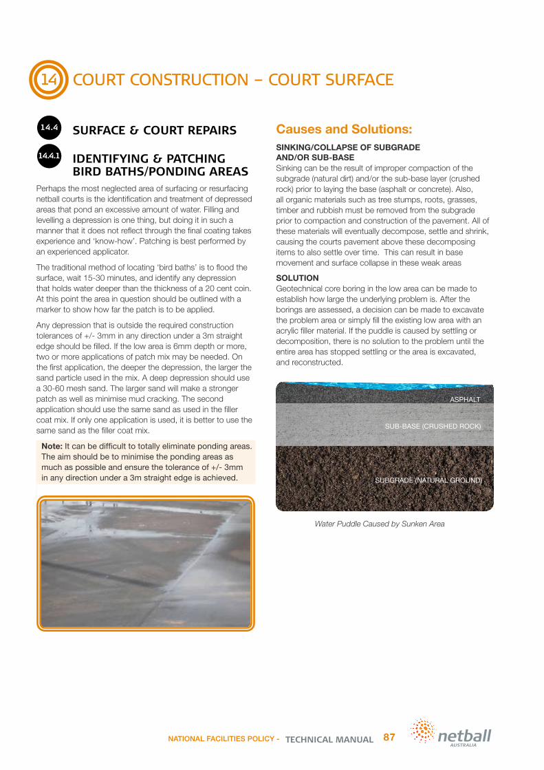
14
COURT CONSTRUCTION – COURT SURFACE
14.4 SURFACE & COURT REPAIRS
14.4.1 IDENTIFYING & PATCHING
BIRD BATHS/PONDING AREASPerhaps the most neglected area of surfacing or resurfacing netball courts is the identification and treatment of depressed areas that pond an excessive amount of water. Filling and levelling a depression is one thing, but doing it in such a manner that it does not reflect through the final coating takes experience and ‘know-how’. Patching is best performed by an experienced applicator.
The traditional method of locating ‘bird baths’ is to flood the surface, wait 15-30 minutes, and identify any depression that holds water deeper than the thickness of a 20 cent coin. At this point the area in question should be outlined with a marker to show how far the patch is to be applied.
Any depression that is outside the required construction tolerances of +/- 3mm in any direction under a 3m straight edge should be filled. If the low area is 6mm depth or more, two or more applications of patch mix may be needed. On the first application, the deeper the depression, the larger the sand particle used in the mix. A deep depression should use a 30-60 mesh sand. The larger sand will make a stronger patch as well as minimise mud cracking. The second application should use the same sand as used in the filler coat mix. If only one application is used, it is better to use the same sand as the filler coat mix.
Note: It can be difficult to totally eliminate ponding areas. The aim should be to minimise the ponding areas as much as possible and ensure the tolerance of +/- 3mm in any direction under a 3m straight edge is achieved.
Causes and Solutions:SINKING/COLLAPSE OF SUBGRADE AND/OR SUB-BASE Sinking can be the result of improper compaction of the subgrade (natural dirt) and/or the sub-base layer (crushed rock) prior to laying the base (asphalt or concrete). Also, all organic materials such as tree stumps, roots, grasses, timber and rubbish must be removed from the subgrade prior to compaction and construction of the pavement. All of these materials will eventually decompose, settle and shrink, causing the courts pavement above these decomposing items to also settle over time. This can result in base movement and surface collapse in these weak areas
SOLUTIONGeotechnical core boring in the low area can be made to establish how large the underlying problem is. After the borings are assessed, a decision can be made to excavate the problem area or simply fill the existing low area with an acrylic filler material. If the puddle is caused by settling or decomposition, there is no solution to the problem until the entire area has stopped settling or the area is excavated, and reconstructed.
Water Puddle Caused by Sunken Area
SUBGRADE (NATURAL GROUND)
ASPHALT
SUB-BASE (CRUSHED ROCK)
NATIONAL FACILITIES POLICY - 87TECHNICAL MANUAL

14
COURT CONSTRUCTION – COURT SURFACE
14.4.1 IDENTIFYING & PATCHING
BIRD BATHS/PONDING AREAS Continued
Causes and Solutions:UNEVEN ASPHALT OR CONCRETEUnevenness caused by improper rolling of the asphalt or the screeding of the concrete. The direction of fall is interrupted by a high area in the surface. This high area acts as a dam, stopping the water and causing a puddle.
SOLUTIONOne of two things may be done in this case. First, the high area may be ground down to allow the water to continue its flow, or second, the low area may be built up enough to re-establish the necessary grade.
In the first instance, the degree of material that may be removed depends entirely on the thickness of the asphalt or concrete.
Many times in dealing with puddles, reduction, not elimination is the only possible goal. If you try and lift an area too much you simply instigate another damming effect to a different area. This is referred to as “moving a puddle”. Sometimes this will be done to get a puddle out of the play area and the outside of the run-off area.
DAMMING CAUSED BY BLOCKING WATER DRAINAGE PATHThis is generally caused by the accumulation of vegetation or dirt along the low side of a netball court. These items build up a dam or wall by which the water cannot penetrate or pass, thus holding the water on the inside of the court. Sometimes these areas can build up so high that the water will encroach back into the court area.
SOLUTIONRemove the debris and scarify around and down the low side of the netball court. If this problem is caused by roots or plants, they must be removed or at least cut back. Landscaping around a netball court adds to the beauty of the court but unless carefully planned, it can cause expensive damage to the court surface and in some cases require the removal and re-laying of the pavement.
Summary of Bird Bath/Ponding Low ponding areas can create a hazard for netball players and they should be repaired. In some cases, a puddle can turn into a very dangerous slip hazard on a netball court. If water sits in an area for a prolonged period of time, algae will grow and silt will accumulate on the court surface. Algae and silt can be very slippery and unpredictable underfoot causing players to slip and fall. This can result in serious injuries. All low areas should be monitored, treated and cleaned regularly to minimise potential slip hazards. This is especially important prior to training and competition play commencing on the courts. This will also minimise the damage algae can cause to the courts acrylic surface and/or base.
SUBGRADE (NATURAL GROUND)
ASPHALT
SUB-BASE (CRUSHED ROCK)
Water Puddle Caused by Raised Asphalt
TECHNICAL MANUALNATIONAL FACILITIES POLICY -88

14
COURT CONSTRUCTION – COURT SURFACE
14.4.2 AREA PREPARATION
On new courts the patch area should be clean. New concrete surfaces should be acid treated prior to any patching. Once the patches are dry the court may then be primed with the manufacturer’s recommended product. On old courts it may be necessary to chemically clean the area with an algaecide.
On old courts it is recommended the area be tack-coated with a dilution of 2 parts water and 1 part binder. A good method of applying the tack-coat is to use a pump sprayer and mist a uniform film over the entire depressed area. Do not allow the material to puddle. The tack-coat should dry in 10 – 15 minutes and enhance adhesion. The area is now ready to be levelled.
14.4.3 APPLICATION OF
PATCHING MATERIALThe professional installer (recommended) is likely to pour the filler mix at the edge of the marked depression and pull the metal screed across the low area, making certain no voids are left behind. If the viscosity of the mix is correct it will require a slow, steady pull of the metal screed straight edge, i.e. there is no need for a saw-cutting action. The metal screed should be held at an angle to the court surface so that the mix is forced down under the screed.
Once the body of the patch is acceptable, the edges are feathered to a fine edge using a steel trowel and brush.
NOTE: Misting the patch surface with the water solution does not affect the mix, because the water is on the surface of the patch mix and evaporates quickly. However care should be taken to only apply a fine mist and not to leave any liquid solution lying on the screeded surface, otherwise skinning can occur, leaving the surface water sensitive and prone to surface delamination later.
14.4.4 GRINDING PATCHES
Often properly installed patches do not require much grinding or sanding. However, if the planarity of the patch is not uniform and/or the edges are not properly feathered, it may become necessary to use a mechanical means to correct the condition. Minor problems may be corrected with a rubbing stone; however a disc or belt sander is fast and thorough.
As a final step in hiding patches, it may be helpful to pre-coat the patches with the filler coat mix.
14.4.5 CRACK REPAIRS
One of the most difficult tasks a contractor faces when surfacing or resurfacing netball courts is related to crack problems. It is relatively easy to fill cracks so that they do not reflect through subsequent acrylic coatings for a short period of time. However, cracks are more than likely to reappear again over the longer term.
Cracks on outdoor surfaces are almost inevitable. The challenge is to keep the cracks to a minimum, and hope those cracks that do return will be minor in nature. In this case, minor means ‘hairline’ cracks, which do not affect the playability of the surface. Cracks which are flat and do not create a trip hazard will still need to be repaired to minimise further deterioration.
Any surface is subject to cracking regardless of whether hot or cold mix asphalt, or concrete base is constructed. It is likely that post-tensioned concrete courts experience the least amount of serious cracking. Furthermore, cracks that do appear only amount to hairline cracks because the tension on the cables keeps them closed.
There are three common causes of cracks:
Thermal expansion and contraction in which a surface reacts to rapid temperature changes
Shrinkage cracks which usually result from a volume change of the surface material soon after installation
Structural cracks which can be the result of subgrade movement and/or failure.
Cracks from volume change can occur in asphalt due to the nature of the mix design, or inadequate compaction. Rapid curing causes volume change in concrete. Of the three, structural cracks are the most severe and the most difficult to resolve.
NATIONAL FACILITIES POLICY - 89TECHNICAL MANUAL

14
COURT CONSTRUCTION – COURT SURFACE
14.4.5 CRACK REPAIRS Continued
The forces of nature are unpredictable and therefore the appearance or reappearance of cracks cannot be guaranteed. Many types of crack fillers and different covering systems have been used over the years, however, there is no known material or system that has proven 100% successful. However, some fillers and systems can deter the reappearance of cracks better than others, but inevitably they do return if there is movement in the surface or sub-surface.
Some contractors put considerable credence in the overlaying of cracks with a membrane; however nature’s force will tear or distort the membrane if the cracks are of a structural nature. Membrane overlays are best used only on hot or cold mix asphalt surfaces that have ravelled, or experienced hairline cracks from volume change. A more expensive method is to overlay the surface with hot-mix or emulsion asphalt; however this type of overlay system is not completely successful and reflective cracking often appears.
Once ground to a level and smooth finish, the surface then needs to be pressure washed with a rotary washer to thoroughly remove all loose and foreign materials before any acrylics can be applied.
Once the surface is thoroughly dried, then all cracks and bird baths can be addressed. The most expedient and economical approach is to ‘V’ cut the cracks and clean out all dirt and/or vegetation, and then fill with an appropriate crack filler. All cracks are filled in and smoothed over with a rubber squeegee or trowel. Normally the crack filler is worked well into the crack with a broad knife. Simply bridging the crack with the filler will not produce satisfactory results. Pressure should be applied on the filler in all directions in order to fill all of the voids, and all excessive material should be removed so that the filler will not reflect through any subsequent acrylic coatings. Once dried, some grinding may be necessary to remove any ridges. Usually a rubbing stone is used for this purpose.
Crack repairs can be filled with a proprietary polyurethane sealant or similar, however, Liquid Bitumen Emulsion is not recommended as outlined in Section 13.4.4 ‘Surface and Base Cracks’ in this manual.
The advice provided in this manual should be used as a guide only, as the manufacturer’s instructions for each individual filler product should be followed for mixing, application and drying procedures.
NOTE: REMEMBER: 1. ‘V’ cut and clean out cracks 2. Tack coat 3. Fill cracks 4. Remove ridges
14.4.6 RECOMMENDATION FOR
LARGE STRUCTURAL CRACKSMake a dry mix of sand and cement (3 parts sand to one part cement), and work the DRY mix into the crack. The dry mix will fill the entire depth of the crack, thus eliminating any voids. Sweep off excessive dry mix to a depth of about 1cm from the top. Pour a solution of binder and water (mixed 1:1) on the dry mix. This will wick into the mix causing it to harden. After the mix dries, use a regular binder mix to fill and level the crack.
The only long term treatment of a structural crack is to remove the area affected, compact the subgrade and install new sub-base and base material. Any other method such as patching, or overlaying will not keep the ground from moving and therefore not prevent the re-occurrence of the cracking. Every situation is different, as every crack is different, but generally structural cracks come back. The question is not if, but when.
NOTE: CLIENTS SHOULD BE ADVISED THAT STRUCTURAL CRACKS WILL REAPPEAR – repairs are likely to be short lived in most cases and are best referred to as short term fixes until a more permanent treatment is possible. See Section 13.4.6 ‘Surface and Base Cracks’ in this manual for further information.
TECHNICAL MANUALNATIONAL FACILITIES POLICY -90

14
COURT CONSTRUCTION – COURT SURFACE
14.5 COURT SURFACE MAINTENANCE
14.5.1 MAINTENANCE OVERVIEW
Every court surface requires regular maintenance.• The courts should be routinely maintained following the
contractors maintenance manual provided once works are completed including the consistent removal of algae, dirt, silt and leaf litter as it collects.
• Ensure all water ponding and silt/slippery areas are removed regularly, this is especially important prior to play commencing.
• Ensure periodic cleaning of the court surface. • Ensure any spills or contaminants, such as drinks & bat
droppings are removed immediately.• Do not permit portable chairs or tables to be placed
directly on the court surface.• Protect the pavement perimeter by maintaining
drainage systems and clearing vegetation to minimise encroachment on to or over the court surface.
NOTE: Not maintaining courts properly leads to costly repairs & premature reconstruction. The lifespan of the surface and pavement will be dramatically reduced if the courts are not maintained as per the contractor’s maintenance manual recommendations.
14.5.2 MAINTENANCE EQUIPMENT
Outdoor courts maintenance equipment:
• A leaf blower to remove all loose and foreign materials before play
• A pressure washer to clean the surfaces every 1–5 years depending on your location. Alternatively Clubs can hire this equipment or employ a qualified contractor
• A squeegee to remove trapped rain water in ponding areas is recommended to prolong the life of the acrylic surface. This is a must prior to competition play commencing
• A metal or plastic spatula, or similar type of scraper to safely remove all bird and animal droppings as they occur.
Indoor courts maintenance equipment:• Floor sander & Floor polisher. Alternatively Clubs can hire
this equipment or employ a qualified contractor
• Scissor mop to keep the surface free of dust, dirt and debris.
14.5.3 MAINTENANCE
RECOMMENDATIONSAll courts require maintenance. This can be minimal for hardcourts, however, the local environment and type of surface installed will influence the amount of maintenance required. I.e.: if the court is placed in a damp environment
with large trees positioned close to the court it will require more frequent maintenance due to the likelihood of increased algae removal, tree limb lopping, leaf removal and additional crack repairs.
Dirt and debrisCourts subject to moist environment, heavy airborne pollution such as dust, tree leaf litter and traffic fumes are classified as high maintenance areas.
• Minimise the dirt and dust on the court surface by landscaping the surrounding grounds and keeping them green and well kept
• Lop any tree branches or trim all vegetation away from the pavement area to minimise the shade and amount of debris on the pavement
• Wipe shoes before entering the court to prevent stones, twigs or other sharp objects being ground onto the surface
• Erect signs at the court entry points, listing the most important dos and don’ts
• Sweep courts with a broom or air blower approximately once per week depending on the severity of surface contamination. Where practical, foreign deposits should be spot cleaned or hosed-off with clean water
• Indoor surfaces should be cleaned regularly with a commercial scissor mop to remove any dust/dirt. Heavy contamination or staining should be removed using a wet scrubber/vacuum machine with soft brush attachment
• If these contaminants are not regularly removed, they will be ground into the topcoat and, with prolonged use, will cause staining and unnecessarily premature surface wear
• A proprietary non-residual liquid organic cleaner, can be utilised. The percentage of cleaner to percentage of water will largely depend on the degree of surface contamination, and should be used in accordance with the manufacturer’s specifications for the particular surface type and stain. After light scrubbing, hose-off with fresh water to remove any residual cleaning agent in an outdoor environment, or wet scrub/vacuum with clean fresh water in indoor environments.
Note: Contact your local authority prior to the commencement of cleaning to ensure the intended works conform to the environmental requirements in your area.
Drainage infrastructureEnsure all court and surrounding drainage infrastructure, including spoon drains and pits are kept clear of dirt and debris to maintain efficient water flows away from the pavement area. This will minimise the ingress of water into the subgrade & sub-base material beneath the pavement and through any pavement damage areas. The base and subgrade material must be protected from water ingress or it is likely to create severe pavement damage as the subgrade swells and contracts.
NATIONAL FACILITIES POLICY - 91TECHNICAL MANUAL

14
COURT CONSTRUCTION – COURT SURFACE
14.5.3 MAINTENANCE
RECOMMENDATIONS Continued
Food/drink, mould growth & tree/plant contaminationIt is recommended that overhanging trees/plants are controlled to prevent excessive maintenance issues. Some trees/plants in particular will cause staining and drop significant debris onto the courts surface.
Food and/or drink spills should be cleaned immediately. Mould contamination may also build up on areas of the surface where plant/leaf contamination occurs or where pooling of water occurs after rain. These areas should be cleaned on a regular basis, using the following method:
• Hose-off foreign deposits with the aid of a stiff bristle broom• Saturate the surface with clean tap water• Use a diluted solution of sodium hypochlorite (liquid pool
chlorine) dilution rate is dependent on the severity of mould growth
• Broom solution over the mould area and soak for 10-15 minutes. Do not allow to dry
• Hose-off the surface thoroughly with clean tap water to remove all of the residue solution. Keep away from plants/animals/children and wear protective clothing, as the solution is a strong bleach (it is a stronger solution than domestic bleach products eg. Snow White)
• More heavily contaminated surfaces may require additional treatments or in severe cases, high-pressure water blasting and sodium hypochlorite treatment. Other algaecides are commercially available.
Test First: Testing of all cleaning methods in a discreet portion of the facility to inspect their effect on surfaces is recommended before any general use.
Note: Do not use powdered Calcium Hypochlorite solution as this will leave a white deposit on the surface after drying. Contact your local authority prior to commencement of cleaning to conform to the environmental requirements in your area.
Specific contaminations: Wildlife droppings, shoe marks, chewing gum, oil and grease• Fruit Bat `Droppings’ – A known threat to acrylic surfaces
is flying fox faeces. This sets hard on the surface and bonds tightly to it. As the faeces dries, it hardens and curls up, stripping the acrylic surface from the base. This is easy to identify as it ranges from the size of a 10 cent coin to a 50 cent coin in size. In severe cases they will cause blistering and peeling, not only of the surface, but also the asphalt underneath to a depth of 3-6mm. In short, bat
droppings are the most natural efficient paint strippers on the market. In areas with flying foxes, it is recommended that regular inspections be carried out to immediately remove the faeces by mechanically scraping them off or by water `jet’ washing. The surface should be patched with the recommended Acrylic surface materials. This will require specific instructions to be followed. The use of an approved Acrylic installer is recommended.
• Bird/Wildlife Contamination – This can usually be removed by a non-residual organic cleaner with a stiff bristle brush/broom and hose-off with plenty of clean tap water.
• Shoe ‘Sole’ Staining/Rub Marks – Only white soled or non-staining/marking shoe types should be used when playing on an acrylic surface. Some ‘black’ rub marks are put on the surface by the type of soles on the footwear. These marks can usually be removed with a non-residual organic cleaner and stiff bristle brush. Some rubber types are quite difficult to remove when they are fresh, weathering will usually allow their removal some time later – prevention is obviously the better method. Shoe sole marking will be more noticeable and more prevalent with new surfaces.
• Chewing Gum Contamination – It is very difficult to remove gum from the court surface. Mechanical scraping of the gum is all that is recommended.
• Grease/Oil Stains from Bikes/Toys – Non-residual organic cleaner is recommended. It may require several applications to remove grease/oil contamination. Thoroughly hose-off the surface with clean tap water after the application of the detergent solution.
Note: Contact your local authority prior to commencement of cleaning to conform to the environmental requirements in your area.
RepairsDeep cuts into the base layer of cushioned acrylic surfaces may be caused by sharp implements such as metal chair legs, heavy steel wheeled trolleys, stiletto heels, vandalism. Chairs and umpire stands should have wooden bases on the legs to minimise damage to the surface. Contact your court builder or a reputable acrylic installer immediately after any damage occurs to prevent further damage from the ingress of water.
Drying the court surface after rainGood Asphalt and Acrylic surfaces should be slip resistant even in wet conditions. If there is ponding identified simply remove any excess water with a wide sponge roller or squeegee and play should be able to recommence immediately.
TECHNICAL MANUALNATIONAL FACILITIES POLICY -92

15
PROJECT COMPLETION OR HANDOVER
It is essential that several main items are checked and signed off prior to project completion/handover, such as:
Check that all required standards have been met, these can be:
• Court Dimensions & Run-offs (see compliance section)• Lighting performance levels – An illuminance (lux) and
uniformity test will be required to verify contractors results – alternatively request a copy of the contractors illuminance (lux) and uniformity test independent report
• Acrylic surface slip resistance – The applicable testing results from the wet pendulum testing should be provided to verify that the sports acrylic surface has met the parameters set in the project specifications.
• Accessibility requirements – Ensure all paths are to DDA standards as a minimum. The contractor should sign off on this
All installed systems and standards required in the specification and design package should be tested and signed off by the contractor prior to handover. This also includes the flushing of all drainage infrastructure.
Pavement layer Compaction Testing & Concrete Strength Testing – the various results reports should be provided to verify that the required parameters set in the project specifications have been met.
Ensure the contractor provides electrical and drainage as-built drawings and all product maintenance manuals
Ensure the contractor is accountable for all defects for a 12 month period as a minimum. Any defects should be reported to the contractor as they are noticed.
All documents and test reports should be provided to the relevant stakeholders at project handover
Ensure that all handover document requirements are included in the specification
Note: All relevant standards and works related to the project must be outlined in detail and requested in the request for quotation/tender/ brief/specification to avoid unnecessary conflict at the completion of a netball court project. Never assume that the contractor is aware of the current standards or the quality of works you require.
In saying this, there is a level of quality that would be reasonably expected as part of a court construction project. Selecting suitably qualified and reputable contractors will provide greater certainty that a positive outcome will be achieved.
See Section 10 ‘Choosing a Contractor’ and Section 11 ‘Project Management’ in this manual for further information.
16 DEFECTS LIABILITY PERIOD
Most contracts should incorporate a Defects Liability Period of some reasonable time period (usually 12 months) to allow for any defective works that may not have initially been evident at the completion of a project to be identified and subsequently rectified by the Contractor.The Defects Liability Period does not commence until it has been agreed that the project has reached Practical Completion. Practical Completion is achieved when all aspects of the project have been completed and it is considered ready for use and fit for purpose.
This status may be granted where the works are essentially completed except for some small items which although specified is not critical for the functioning of the facility. An example of this would be where all works were completed except the supply of a specified leaf sweeper for the court was delayed by a week due to a misplaced order by the manufacturer. In this case, Practical Completion could be granted for the project, subject to the supply of this outstanding item as soon as possible.
Any defects should be reported to the contractor as they are noticed. It is very important that a final inspection is conducted prior to the defects liability period ending to ensure all defects are rectified by the contractor within the designated defects liability period.
NATIONAL FACILITIES POLICY - 93TECHNICAL MANUAL

17
LIFECYCLE COSTING
When choosing elements of a facility the ongoing maintenance, resurfacing and renewal costs need to be considered in addition to the capital/establishment cost. For example, choosing a low price acrylic surface with a shorter service life may cost more in the long run than if a quality product was installed in the first place. Replacing a budget product may also require significant effort and expense to remove the failed product/infrastructure prior to replacing it with a quality product.
Similar issues apply for fencing, lighting and in particular, base construction.
17.1 SINKING FUND
A Sinking Fund is recommended to ensure that the Club, Association, League or Council can afford to keep their courts in good working order and renew them when required. Some costs to consider and allow for are:
17.1.1 ROUTINE MAINTENANCE
All Courts approx. $500 minimum per court per year:Clubs and Councils should budget to have the court facility regularly maintained. Including:
The clearing of all drainage infrastructure – spoon drains, swale drains, agi drains, drainage pits and pipes
The cleaning of all light fitting lenses and lux level testing for functionality.
Note: The cost for this item will be greater if the court surrounds are heavily treed.
17.1.2 COURT CLEAN
Acrylic Surfaces approx. $450 per court every 2-3 yearsProfessional Cleaning: should be done every 2-3 years, however; if there are trees nearby and the courts are in a cool climate they may require a clean every 2 years. Cleaning courts within these time frames will maximise the longevity of the courts and prevent the surface becoming slippery over time.
The price to professionally clean is approximately $450 +gst per court plus travel expenses (at current 2015 rates). Alternatively, the Club could hire the machines and clean the courts themselves, however, keep in mind that this can be a big, time consuming job. Poor volunteer numbers may jeopardise the DIY approach leading to the courts being left in a slippery and unsafe state.
17.1.3 ACRYLIC RESURFACE
Resurface approx. $7,500 per court every 7-10 yearsResurface Timeframe: Time between re-surfacing is approximately 7-10 years depending on the courts usage, the court surrounds, environment and climate.
This would involve:
Cleaning
Minor repairs
Two top-coats
Reline-mark.
Note: If a cushioned acrylic has been installed, there is no need to replace the rubber component of a Matt lay cushioned system as the cushioning lasts indefinitely. A basic resurface is all that is needed. If a Liquid Applied Rubber (Wet Pour) has been installed, there may be a need for additional cushion layers prior to resurfacing with the acrylic coatings. This will be at an additional cost.
The price to resurface is approximately $7,500 + gst per court plus travel expenses (at current 2015 rates).
17.1.4 FULL RECONSTRUCTION
Asphalt Courts approx. $70,000-$100,000 per court per 20-25 yearsAsphalt courts require routine pavement repairs if and/or when damage occurs. Small cracks can turn into large pavement failures if water is allowed to penetrate to the sub-base material. Recommend regular repairs to maximise an asphalt courts lifespan.
Asphalt courts can require resealing or total reconstruction within 25 years. It is important to plan for this renewal and equally important to make sure the works are done to a high quality to minimise ongoing repairs and premature rebuilds.
Note: the lifespan of an asphalt court can vary greatly depending on the quality of the original design and construction, random environmental factors (floods), degree & timing of ongoing maintenance & repair works. The above estimates are to be used as a guide only.
TECHNICAL MANUALNATIONAL FACILITIES POLICY -94

17
LIFECYCLE COSTING
17.1.4 FULL RECONSTRUCTION Continued
Concrete courts approx. $100,000-$130,000 per court per 40 yearsConcrete courts are long lasting if designed and constructed well. They should require minimal routine pavement repairs and only require repairs and resurfacing with an Acrylic as per the manufacturer’s recommendations (approx. every 7-10yrs).
It is important to plan for this renewal and equally important to make sure the works are done to a high standard and quality to minimise ongoing repairs and premature rebuilds.
Note: The lifespan of a court with a concrete base can vary greatly depending on the quality of the original design and construction, random environmental factors (floods) and degree & timing of ongoing maintenance & resurfacing works. The above estimates are to be used as a guide only.
NOTE: 1. Cost escalation from the 2015 figures provided should be added to the above costs. 2. Costs for maintenance and reconstruction do not include fencing, shelters or light infrastructure as many courts do not have these or the level of infrastructure varies greatly from site to site. Quotations or cost estimates for these items should be sourced if they are applicable to your facility. 3. Actual project costs may vary markedly, depending on market conditions at the time of construction. 4. The above cost estimates are to be used as a guide only. Up to date, current cost estimates should be sourced from an independent industry professional when budgeting for maintenance and/or court renewal programs.
18 INDOOR NETBALL COURT FACILITIES
This manual does not provide detailed indoor netball court facility design and construction recommendations.In saying this, indoor netball court lighting and surface specific recommendations are provided in the following sections:
Section 2 ‘Compliance’, Section 9.7 ‘Lighting’ and Section 9.12.6 ‘Indoor Court Flooring’.
Clubs, Associations, Leagues and Councils who are considering an indoor netball court development are encouraged to seek professional advice when planning for a netball court project. State/Territory Member Organisations may be able to provide advice and guidance regarding indoor court developments.
Like outdoor netball facilities, all indoor facilities should be designed and constructed to ensure compliance with the current relevant standards, this includes (but is not limited to); compliant lighting, court dimensions and run-off zones. Netball facilities should comply with relevant current standards including the Disability Discrimination Act (DDA) 1992, provide all abilities access as per AS1428.1-2009 & comply with the current National Construction Code (NCC) Series 2012 vol.2 Building Code of Australia Class 1 and Class 10 Buildings. Other good practice documents & standards in circulation should also be considered along with local government and/or specific funding requirements for each individual project.
It is recommended that indoor netball facilities are designed to be inclusive to all members of the community and have provision for appropriate amenities and supporting infrastructure to support the level of play expected at the venue.
NATIONAL FACILITIES POLICY - 95TECHNICAL MANUAL

19
DOCUMENT CONTROL
Disclaimer:
As stated in Section 1 ‘Introduction’ of this manual, it is important to note that this manual is not intended to replace professional site-specific advice from the likes of engineers, design consultants, architects and registered court builders. This manual has been primarily produced to provide members of the netball community with assistance to understand the concepts and technical aspects of netball court planning, design, construction and maintenance. The information provided within this manual is the most accurate known to the writer at the time of publication. The opinions and methodology used and known to others may differ to that of the writer. This manual is to be used as a guide only. It is incumbent on the user to confirm dimensions with the state/national/international sporting body and source guidance from technical experts as outlined in this manual prior to commencing a netball facility project.
TECHNICAL MANUALNATIONAL FACILITIES POLICY -96

20
ACKNOWLEDGEMENTS
Netball Australia engaged Gemba Group & 2MH Consulting P/L to provide the content for this manual, both technical and information based.It is envisaged that this manual will help to further develop and improve the sporting facilities for Netball in Australia.
The Netball Australia Technical Manual has been developed in collaboration with numerous stakeholders. Netball Australia wish to thank all of the organisations and individuals who have contributed information, diagrams, photographs, opinions and suggestions for incorporation into this publication. The contribution of the following organisations is gratefully acknowledged:
• 2MH Consulting for providing the Technical Manual component of this document
• Gemba Group for providing the National Facilities Policy
• All Member organisations for their contribution and work on the compliance elements in the Technical Manual
• California Sports Surfacing for their contribution of netball specific acrylic surface information and providing the Rebound Ace Technical Manual as a resource for inclusion of relevant information and photographs within this document
• APT Asia Pacific Pty Ltd for their contribution of netball specific surface information
• Martin Butcher Lighting Design for extensive works on the indoor and outdoor lighting recommendations
• Carl Strautins and the team at Safe Environments for their expertise, review and recommendation of available slip resistance standards and testing available for sports surfaces
• Tennis Australia for providing the TA Technical Manual as a resource for inclusion of relevant information within this document
• Department of Sport and Recreation Western Australia for providing the ‘Sports Dimensions Guide for Playing Areas for Sport and Recreation Facilities 2008’ as a resource for inclusion of relevant information within this document
• Otter fencing for providing drawings for the relevant fencing standards recommended in this Technical Manual.
• Marcom Write for formatting & proofing works
• Brad Welsh from OneDegree.com.au for the concept design and layout of the manual.
NATIONAL FACILITIES POLICY - 97TECHNICAL MANUAL

Netball Australia191 Johnston Street
Fitzroy Vic 3065
Phone: 03 8621 [email protected]
netball.com.au
Copyright © 2015 Netball Australia
All rights reserved. No part of this publication may be reproduced, stored in a retrieval system, or transmitted in any form or by any means without the prior written permission of Netball Australia.