Embed Size (px)
Citation preview
REPLY TO ATTN OF: Gp
TO:
NATIONAL AERONAUTiCS AND SPACE ADMINISTRAT~N --
WASHINGTON. D.C. 20546
~ s ~ / s c i e n t i f ic & Technical Inf omation Division Attention: Mi68 Winnie M, Morgan
of office of Assistapt General Counsel fo r Patent Matters
SUBJECTt Announcement of NASA-Owned U, S. Patents i n STAR
In accordance with the procedures agreed upon by Code GP and Code USI, t h e attached NASA-owned U, S. Patent is being forwarded f o r abstracting and announcement i n NASA STAR.
The following information is prwidedr
U, S, Patent No, 8 q.576; /35- -
Government o r Corporate Employee
Supplementary Corporate Source ( i f applicable) :
NASA Patent Case No, t
NOTE - I f t h i s patent covers an invention made by a corporate employee of a NASA Contractor, the following is applicable:
yes 0 NO I 3 Pursuant t o Section 305(a) of the National Aeronautics and Space Act, the name of the Administrator of NASA appears on the f i r s t page of the patent: however, the name of the actual inventor (author) appears a t the heading of Column No. 1 of the Specification, following the words . . with respect t o
Enclosure I
Copy of Patent o i ted above 5 I
2 I 2 (NASA CR OR TMX OR ~b NUMBER) (CATEGORY) LL
https://ntrs.nasa.gov/search.jsp?R=19710017159 2018-05-19T20:24:46+00:00Z
PATENTED APR 2 7 1971
SHEET 1 OF 2
I KO,
PATENTED APR 2 7 1971 3,576,135 SHEET 2 OF 2
IRVENTOR: HUBERT F A.TSCHUNKO,
United States Patem j 72 Inventor Hukf i F. A. TxlruAo iSO] Refemnces Cited
IMiltorn, Mass. UNITED STATES F'A'TENTS [2 1 ] Appl. No. 874,733
........................ 1221 Filed Nov. 7,1969 2,473,566 611949 Brassell 741424.8 ......................... (451 Patented Aps. 29,1971 2,943,508 711960 Musser 74/424.8
173] ~~~i~~~~ The United states of :\merim as repl-csenrilea 2,946,235 711960 Musser ......................... 741424.8 ......................... bv tRe AdminisWatoa of the Ndional 3,404.580 10/1968 Valenti 74/324.8
Aeroiiautik~ and Space Adknidratioa; Prtrrmry Examiner-William F, O'Dea As~tstant Examiner-Wesley S . Ratliff, Js. Attorneys-Herbert E. Farmer, John R. Manning and Garimd
T. McCoy
I541 ELECTROmCHANlcAL CONTROL ACK'hITOW A ~ ~ C T : A motion-transmitling device a doublz SYSTEM differential screw principle is disclosed. One diEerential screw 14 Claim, 5 Drawing Fig& rnechmism including first and second sets d threads of
.................................... [52] U.S. C! ... 74189.15. different itch is owrativelv couvled to another difkrentia:, 741424.8 screw mechanism iaving tkrd a id fourth sets of threads of
[ 5 1 ] Int. CI ..................................... d 27/02:, different pitch. By providing the first and second sets of FE 6h 1:G5 threads with a pitch difference not equal to thsc difference in
[501 Field of Search ............................................ 74189.15, pitch between the third and fourth sets of threads, a doubie 424.8 ( A ) , 424.8 (Bj ; 424.8 (6:) differential movement is established.
3,576,135 1 2
ELIECTROmCHANICa CONmOL ACTUATOR rotatnon of the prnmary and secondary clrsve members in ;he S Y m M same d~rectlon produces axla8 movement oftrhe actuator
relatnve to the fixed suppet over a drstdnce equzE to the
ORBGIN OF THE INVEWION d~fference between the relative movements produced betweein
5 the primary dnve member and coupl~ng member and between The lnventlon described hereln was made by an employee the secondary drive member and actuator
of the &innted S ~ t e s Qjovernment and mw be manufactured Another feature of the ~nventron 8s the provsssoo of 8
and used by or for the government for governmenla1 purposes motlon-transm~tt~ng dev~ce of the above type ancieidcng a without the payment of any royalties thereon or therefor common drlve mechannsm for rotat~ng the pnandry ard
secondary dnve members at the same angular vebcnty Cse of BACKGROUND OFTHE INVENTION a common drnve mechan~sm helps lnsure predictable *c$uatoa
$&is invenhon to a motion-transmitting movements by accurately establishing the relative movement d e ~ c e and, more parpicularly, relates to a microactuator lat ti on ships existing betwen the various components.
of execufng displacements in the range from less than I Another feature of the invention is the proviskon of a
50 A. to several centimeters. motion-transmitting device of the above type including ~i~~~~~~~~~~~ are required to the adjustments, separate drive mechanisms that pemit independent rotation
alignments, collimations and deflections of various optical and of the primary and secondary drive ~ e ~ ~ ~ s . of
precision mechmacal elemen@. previous actuators of this type independent drive mechanisms permits r~PiiPion 61f the are based on the pinciples of magnetostriction, 20 primary and secondary drive members in opposite dircctiorls eiectrosthicpion, or &emal expansion. Also known are thereby accelerating relative movement of the actuator with devices utilizing liquid or gas pressurization to prduce linear respect to the fixed suppofi and facilitatin~g use OF the devicc movement. The prior afi devices exhibit various disadvantages for relatively coarse adjustments. including requiremen@ for p w e r consumpfon to mainlain Another feature of the invention is the provision of a psitionas, requiremen& for applied heat that frquently cause 25 motion-transmitting device of the above types irtcloding a uncontrolled displacements because of thermal surges, and compression spring member that mainbins pressure betwean opra6ons entailing step displacements that are individually the first, second, third and fourth sets d' threads. The bias HQO large for many applications. exerted by the spring member eliminates dctrirnental backlash
The simplest and oldest actuator is the single mechanical or frontlash of the coupled elemen@. screw. Although extremely reliable in its range of operations, 30 A featured embodiment of the ixaventicrr: co:mprises a the mechanicd screw obviomly is not capable of producing motion-transmitting device of the above types wherein tbc displacemenes in the microrange. A well-known improvement primary, secondary and coupling memben are all hollow of the mecl~micd screw is the simple differential screw that cylinders; the first set of threads is formed by external threads utilizes the diFference between a pair of linear movements on the primary drive cylinder and internal threads oil the fixed produced by a single drive mechmism. The fine Ajustment 35 suppfi; the second set of threads is formed by internal capability ofthe diEerential screw is substantidly greater than threads on the primaxy drive member and external threads on the single mechanicd screw bur its ultimate fine adjustment the coupling member; the third set of 1:hreads is fc~sn~ed by capability is lifited by mxhining accuracy. internal threads on the coupling member and external threads
m e object &is invention, thesefore, is to provide a on the secondary drive member, and the fourth set of threads relatively simple and reliable actuator capable of executing 40 is formed by internal threds on the secondary drive memfissr linear displacements in the range from less than 50 A to extemd threads on the actuator. "n;.is arrangement several centimeters. lorovides the desired double differentia! relative ~nuvcment~s
with a mechanical assembly that is extremely s~rnple and , , compact. L).J .
The invention is characterized by the provision of a motion- trmsmitting device including a pair of operatively coupled BRIEF DBdSR1~8ON OF THE DRAWINGS
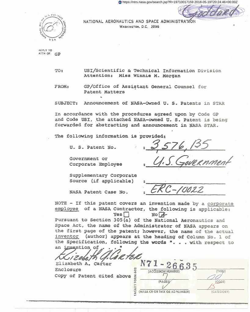
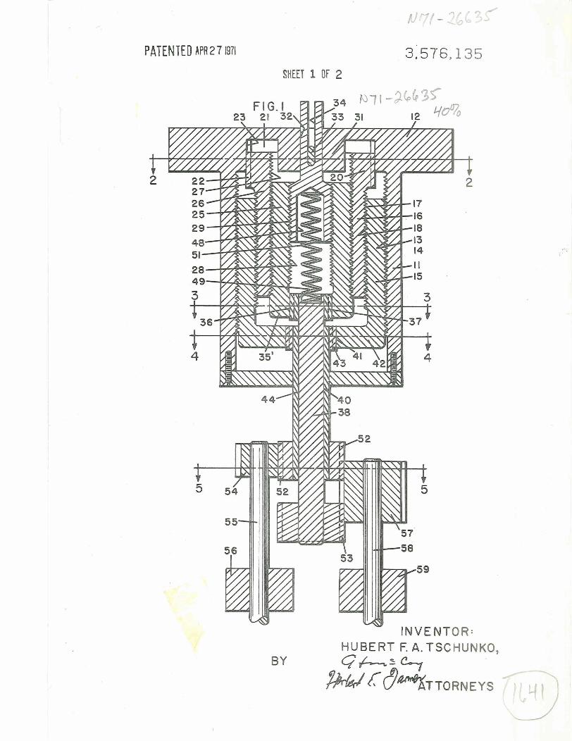
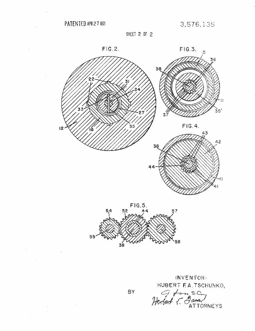
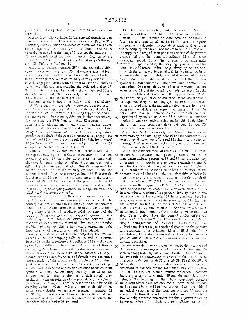
diflerential screw mechanisms. &e of the mwhanisms The= and other objects and features of the ,nven~icn Ba,i~i c o ~ r i s s a primary drive member engaged by a first set of become more apparent upon a perusal of the following t ~ r ~ ~ with a fixed S V P f l and by a second set of threads 50 specification eaken in conjmction with the =companying with a coupling membr. The o&er differentid screw drawingwherein: mechanism c o m p ~ ~ a Xcondahy drive memhr engaged by RG. 1 is an elevational vview in cross section iillilsrrating a a third set of threads with the coupling member and by a preferYd of the invention; fourth set of threads with actuator. BY providing the first FIG. 2 is a cross-sectional view taken along lines &t in FIG. and second sets of threads with the same sense but different r .
4, pitches a digerential movement is obtained between the F ~ G , 3 is a taken along lines :L3 In FIG primary drive memkr and the coupling member. Similarly, *. brovidLg Ihe fourth seFS 'f wirk the same "FIG, 4 is a sectional crosss-sectiond view e;keo Lanles sense but diBerent pitches produces a differen~d movement in R ~ . and
the secondary drive member and the actuator. 60 FIG. 5 is a cross-sectional view taken along Ems S-5 in FIG Finaliv. the Rrst and second sets of threads are provided wlth a a
di~ference in pitch that is itself different than h e diflerence in ''
pitch beev~eehl the third and fourth sets d threads so as to OFTHE ~REH;~ERRED EMBODIMENTS esablish relatsve axial movement between the coupling member and actutop in respnse to simultaneous romion of 65 Refeaing now to FIG. 1 there i s shown a horEow C Y ; ~ ~ Q ~ P C ~ L she p n m w m d =condar)i dpive members. According to this Suppofi housing 11 having a flange 12 suatabie foi attachment mmgement extremely small and precise axid movements of to an accommdating surface. Enga@ng ~nrernal threads 13 the actuator member are obtained by appropriate rotation of on the suppofi housing 11 are external threads 14 on a the p h i m q and secondary drive members. primary hollow drive cylinder 15. A hollow cylrradrical
One feature of the invention is the provision of a motion- 70 couplung 16 has external threads 1'7 that engage internal tmsrariRiing device of the above type wherein the various sets threads 18 on the primary drive cylinder IS An annular recess d threads are pro.ovidd with senses such that rotation of the 21 in the inner surface of the flange 12 recesvas a ternanal p~mary and s e c o n w drive membes in the same direction pofiion of the coupling 16 and pemrts axrd movement prduces movement of the coupling member and actuator in thereof. Rotation of the coupling 16 ns pre\iented by key 22 o p p i t e direcliom relative tie each other. In this embodiment 75 extending from the outer surface of the te~rnlnak coeplang
3,576,135 3 4
~ O ~ R O P and projectrng anto axial slots 23 in the annular The difference In pitch proveded bedweep the first ,n 7"
recess 2 4 second sets of threads 13, 141 and 17, 18 1s shghelj c~nFe~-,: e A secorudnry holing~ cyiinder 25 has external threads 26 that than the difference rn patch provided between the ~ w ~ r d ,~md
Ingage r~trsnd in+s;wds 27 on the cylnndracal couplang 16 The fourth sees of threads 26,27 and 2 8 , 2 W $ h variatlor, In DILL^ se~cndinr: drwz cylinder 25 also possesses anternal threads 28 5 d~fferences 1s esvabilshed to provide unequal axial \e!oci:qe~ fhar engage cxscrnal threads 29 on an actuator rod 31 A for the couplnng cylnnder 16 and the actuator rod 31 relafinve to ,elatra' apercure 32 in the flange 12 receives the actuator rod the support housing 11 nn response to rotatson of the prarnasy 31 anif wrmif\ a d d movement thereof Wotataon of the cylislder BS and the secondary cylinder 25 at the samc -ictuaior rcJ 31 -s prevented by a key 33 that projects through roeational speed Snnce the directnon5 of dqffereatial
..lot 35 {li-16 2 J 11- the flange 112 l o movement expenenced by the coupling cylander 16 and t k e I rxed ii. a reeratrmt poption 35' of the secondary drive actuator rod 31 are determined, respectively, by the direc ~ I ( T ~
.yiw~des 25 $s nn annular gear 36 that engages external teeth B R whach the pnmary cyhlsasder 15 and the secondary cyi,rd-r i. 7 on ,+ soliit a r i c ~ k ~ d t 38 A sarilalar annular gear 41 is fixed 25 are rotatnng, approprsately selected dsrectaons ef wkrrana l o n rcc:, r m t wfl\\\ I 42 ofthe pnrnary drive cyli~ader 15 The can produce d~flerentral axial movements of the cstlpirng gear 41 .n$ages e~ternal teeth 43 on a hollow dnve shaft 44 cylander 16 and actuator 39 whsch are elther addrtave or ~1 I oil-ens: 6 wbih jrnd encompasrng the solad drave shah 38. opposition Opposing directnons of a a a d movemen1 1-y khs Wcta~?ed i ~llr~j- :ecesses 48 and 49 in the actuator rod 31 and actuator rod 31 and the coupling cyPlnder BQ sese It In axl-' :h- *>as!ir! J-we s h ~ A 38, respectakely, and exerting a force movement of the rod 311 reiatrve to the JUQPQP$ horavmi: 9 1 a# a ii?erebtwezr rs a cfbapression spnng 51 20 reduced velocnt) equal to the dnfierence in sndnid-lrl \el >c r-
!'erir4rniP!ng tat hnllov, drave shd t 4 4 and the solid drive aes experrenced by the coupling cylsnder 16 and the -oJ 3' n,~ia 38, ~~pe-trbesgi, are radrdly outward drrected x t s of S~nce, as noted a h v e , the ~wdrvidual velocities are t h e ~ s c ' ~ p s
1eo.n 52 LI? 53 A > p ~ - gear 54 IS fixed to the end o f a shaft 55 generated by dnfkrenttal screw mecban~sms, at v 111 ae Giciap'Ie~ for d u ~ slclkeniient rn a bearing support 56 and for apprecmted that the reduced do~zble dfferrentaa' tclocl-y ,~! t~chl -~oi 10 1 4'cl'ldbk r'9tary dnvc mechanawn (not shown) 25 experienced by the actustor rod 31 selat~ve to the supperf Inotner i p ~ r g e a 57 IS fixed to a shaft 58 adapted for both housing 11: can be much Sower than the indsvjdalal pizioclrror 3! 7otd-y 14 xong tsdlnd rnovernena wrthim a bearrng support the primary and secondary drive cylinders 15 d ~ t i 2" 59 T% .ha;: iB Jso ss adapted for atbchment to a surtable Extremely precise movements, therefore, can 5e rc,ioe - v r%= roialy dmve rntchbenism (not shown) In one Iongrtudinai the actuator rod 311 Convensely, common diiect~ons of LA* 3
wvraun of the "id? 58 the gear 57 simulwneously engage5 the 30 movement by the couplnng cylander 16 and the actuator risl Jr ~ i x r h 52 s ~ ~ ~ 3 55 or both the solad shait 38 and the hollow shaft result en axnd mo~~ement of the rod 31 reldsve to tbc suppvv 4 ihatvn in FiG 1 b and in a second pait ion the gear 59 houslng lii at an increased velocaty cqlaal ia the covbiwd eriTago\ ooi 8, u ~ e te-th 53 on mild shdt 38 endrvidwl velocltrcs of the two elements A f~xst sci 1.1 'h-<,I& compnsang the nntemal shteads 13 on A preferred embodiment of the anventnon entail- a t h r e d
L'I; S U ~ ~ O F I )?i.usrng 11 and the external threads '84 on the 35 relatronshap between the premdry drtT~sen3~~' screw 3r ~ n q cyia.ader 15 have the s m e sense (,ns commonly rnechanlsm sncludlng elements 15 and 16 and the &:OF~J.BY
td-ntafi~d sr ert$a,r right- or left-hand devgnatlons) but a dageferentaal screw mechanism nncluding elernen& 15 and 31 i$r!Cerea-n prtch *hdn a second set at threads comprising the such that the reduced differentia! axral velocity of 'I.:: acruatov ntemi ti,eacs 8 on the pnmaay cylinder 15 and the 31 ts p r~duced by ;onamon dnrectroi~s cf r3t,ltif*-i of the , \tena,ib :barcads 1"' an the couplrng cyrsnder 16 Becausc the 40 primary drave cyl~nder 15 and the \tcandasj d ~ ~ v e cylmde~. :I" 5ns $hri..~l~d we 13 r,nd 14 h a the same sense as the s e ~ o n d 4ccordnng to Chnb asrmgement, rotalron of the d m e sSi.lft ,b qhtead 97 - ~ d j 18, i'otataon of the pnmary cyilndei 15 and attached gear 57 (FIG I ) in o w directlor ouodir z< 2 ~ x 3 ~ -3 a( ernent 01 &h0l element at-jd of the rotat~on VII$ the engagang teeth 52 and 53 of b<-i~- One ,olqP
rcr~*~c*ial' 4 \eyed mupiing cylinde- 16 1.1 oppmate directions shaft 33 and the holla~v shaft 44 ~ l g the opposite d 1-c la_.? IT-r t aata,~ to the - u ~ p o ~ r t housing B I 45 ~n turn anduces rotation> of the pramary drive cyl,tnde~ BS <~*d
h F d w ~ d i w ~ 1 *E" i t iascatres of these axaal movemen&. are not the secondary dnve cylnndes 25 la a common i'ilre~~ro- ~qbal sex, dsr' r'?e vonun:BiPrrn pnaches provided The lsroducing axia~ movenaent of the actbaator iod' 31 re;atr \it L ,
p ) i m w ~ cy irxikr ;Q and the coupling cylinder 16 therefore the support housing Id at the reduced deflcrenlaa' di
furctro-i a, 6*!Tccrhtraii screw mechanism wherean rotation of velocity Obv:oualy, the dnrectnon of the actuators rb i s 2 ria' ihe prrq,,sv c>Iia$cx 85 prduces anal movement of the movement as detemined by the direction m w h ~ h the d rve c u r ~ l rg ah d,ive to the fixed support housing 111 at d. shaft 55 as rotated Thus, the deslred double diifercrai . rziuc e q ~ a i to qil:: diRerence between h e andivadual uaal movement of the actuator rod 31 3s provided with a reiatltri: i Jsic I es or both elements 15 and 16 Obvnously, the diaectron simple mangement of elements Furthermo~e, tkts
$91 whstn I nc cr~uylrrig cylander 16 moves IS determined by the 55 ernhdrment Insures equal rotational speeds for tbe orr;r : d!rcctaoa ns wh~ch h e prnmarp, cylnnder 15 is rotated. and secondary dnve cylanders 15 and 25 theaeby C I ~ F 31
firn,'ilriy a h r d set of threads compns~ng the antema! estdblrshang the relat~ve movement relataonshnp bet\ -e- threads 77 osl the couplang cyisnder 16 and the external palr of d~fferent~d screw mech&qasms a d enhai-c 32 1 -- rhe ,dc ?6 an the ;.con&q dnlie cylander 25 have the same actuators precisaon x4se 3d1 a aiEe:ent pstch than a fourth x t of threads 60 In the event that more rapid movement by the actuarc os. ~.-ornpwrg ~hs : mksrnd threads 28 on the secondary cylsnder 31 1s des~red for making coarse adjustments, the dnve illn n 5% 25 and ?he exterial threads 29 on the actuator 31. Agann ns shifted longtudindly out of contact wath the teeth 52 or ."e bemuse thc third and founh sets of threads have a common hollow shaft 4 (downward as shown an FIG 1) so 2 5 to sense, rotatma8 of the xcondary dnve cylinder 25 produces engage only the gear teeth 53 on shaft 38 The shafts 55 a d axral rnovernevt of that element m d of tihe rotatrondly keyed $5 58 are then rotated In the same directiosa p r o d u c ~ ~ g oppobr:e ,;rumator rod 38 n;n opposite directions relallve to the coupiang dlreechons of roaaion ;For the solid shaa 38 and the n o h a cylsnder 16 Thus, he secondary drive cyiander 25 and the shaft 4-4 TThas an turn induces opposnte directiori~ of rotd~lo- actuator red 38 also function as a dlEerentlal screw for the primary drave cylander 15 m d the secondary Lnrie m:chmiralsbw. wnereta, rotation of the secondary dnve cylinder cyllnder 25 resultang an the above described addit 'iY
25 produces & ~ d movement of the wtuatoa 31 relatnve to the 70 movement wherein the actuator rod 31 moves axlally vejan, 2
coupllrfig cy6~ndel 16 at a velocity equal to the dlfgercnce to the suppofl housrng 1 8 at a velocity equal to t592 c0mba7~O bnwecr the andrmdeaai velocaties experrenced by members $5 nndlv~dual ve$ocrtaes of the coupling cylinder 16 and hc and 31 Agarn, the dlrectaon of the actuator" ddnfferentrai axaal actuator 31 Thus, the dnsclosed actlaator can psovlcc c i5cr a movesent rs dependent upon the dnrectlon an whlch the low veloc~ty actuator naovement for fin@ adjus~m~vl~s a a.: w~widil-lr ~ ~ Y P I C cyhder 25 15 soaatec! 75 ancreased velocaty fo: aciabnbelp cnarze adjus.r-e~~b i* r a
3,576,135 5 6
the direcfion d actmtor rod movement is detemined by the revolution of the p~mary cylinder 19 results in an upward directions in which the sh& 55 and 58 are rotated. movement of 0.020408 inch on the support housing El. As
According lb) a spci6c exmplle of the invention, the first described above, the roQtively keyed coupling cjilinder 16 set of threads 13 and 14 is provided with a pitch of one forty- simul~neously moves 0.020000 inches downward on the ninth inch, the second set of threads 117 and 18 and the third 5 primary cylinder 15 producing a net upward nrovernent of thc set d threads 26 and 27 are provided with pitches of one- 0.020408-0.020000 inch=0.000408 inch relative to the fiftieth inch, m d the fourth set of threads 28 and 29 is support housing 11. The corresponding countercEakwisa: provided with a pitch of one Bdty-first inch. The sense used for revolution of the secondary drive cylinder 25 produces threads 13 and 14 produces upward movement (as viewed in downward movement thereof of 0.020000 inch on the FBG. 1 ) ofthe p ~ v dd.ve cylinder 15 on support housing 11 coupling cylinder 16. Simultaneously, the rotatively keyed in reswnse lb) c l m k ~ s e ro(ation and the sense used for actuator rod 31 moves 0.019608 inch downward on the threads 2% and 27 produces downward movement of the secondary drive cylinder 25 and, therefore, undergoes a net secondaay drive cykinder 25 on the coupling cylinder 16 in upward movement of 0.0200 .01960M.@30392 inch. respnse to cicack* rohtiitisn. Assuming then the operative , As before, however, the secondary cylinder 25 is also njo~ed psition shown in FIG. 1, cmnterciockwise hornion of the relative to the suppo~r housing 11 by axid movement of the shaft 58 induces clwkwi= roution of the shafts 38 md 44 artd coupling cylinder 16 on which it is supipned. As described accordindy of the primary a d scondaay drive cylinders 15 above, this movement is 0.0(80408 inch upward relathre to the md 25. One clockwi* revolution of shaft 38 moves the suppr2 housing 11. mus, the composite axid movement of primary cylinkr 15 axidly upward l/4H.O20@8 inch on 20 the actuawr rod 31 relative Po ?he suppfl housing 113 in the suppart h w i n g 11. SimdP;bneously, the roatively keycd response to one revolution of the shafts 3% and 44 in opposite abupling q l i d e r 16 moves 1/50-e).020W0 inch domward directions is Q . Q 0 0 4 0 8 $ 0 . 0 0 ~ 3 3 2 ~ . ~ 3 8 ~ 1 inch in an up- on the ipemry cylinder IS. n u s , the coupling cylinder 16 ward direction. It will be obvious that revofention of each of the e x p ~ e n c e s a net upwwd movement of 0.020408-0.0200@ shafts 38 and 44 in the oppaite directions wiil produce in a =.(B.880m8 inch relative to the s u p p a howing 11. The 25 similar manner the same mount of actuator rncvement in a comespnding c l ~ b G s e revolufion of the secondary drive downward direction. A simple a d j ~ s t ~ ~ e ~ t d :he drive cylinder 25 moves it 1/58=0.82W0 inch dowmwahd on the mechanism, therefore, increases by two orders of magnitude mupiing cylinder 16. Simulraneously, the roeatively keyed the velocity at which the actuator rod 31 moves in r s p n s e to acte~apor rod 31 m v a 11514.019608 inch upward on the a given roQtiona1 drive velocity. n i s feature greatly hcii- se@onw drive cylinder 25. The actuator 31, therefore, 30 itates use of the device for making relatively coarse adjust- undergoes a net &wanward movement of 0.02 .019608 ments. =6).W3"B inch on the secondary cylinder 25. However, the Obviously, many modifications and variations of the present s e c o n h y cylinder is also mved relahve to the support invention are possible in light of the abovc teaching. For hornsing 111 by axial movement of the coupling cylinder 16 on example, other arrangernenb of the double difiereiatiai screw which it is supgofled. As noled above, the net movement of 35 mechanisms can be used including both parallel and inline the coupling cylinder 16 is 0 . W 0 8 inch upward relative to connections. Also, pitch sense relationship other than those the suppf l housing B B . n u s , the c o m p i t e axial movement specifically desc~bed can be used depending upon the desired d the netmtor rod 31 relative to the suppon housing I I in objectives. r e v = to QM c l ~ k w i ~ revoluhon of the s h a h 38 and 4-4 is k claim: O.OW408-0.0003920.W 16 inch in an upward direcdon. 40 9. A motion-transmitting apparatus comprising: Br will be obviow, that one counterclmk\wiw revolution of the infixed suppfl, shafts 38 and 44 Gll prduce in a similar manner the sarne a primary drive mems adapted for a.tp!ary m~i~cn~esr t and mount d axid actuator movement relative b the support engaged by a first set of threads with said fixed suppu%, homing B 21 but in the oppsite direction. said primary drive means dapted for axial moven%m.t
The above exmpiie i1lus@a~s the improved fine djustment 45 relative to said fixed supphl in response to rotzaition, apabiliky of the invention. A single revolution cElf actuator a secondary drive means adapted for nYiary movement, movement indum 0 . W l 6 inch of axial movement by the a coupling means engaged by a second set of threads with x t w t o r rod 31. This is three orders of mqnitude less than the said peimary drive means md by 2s third sot of threads mid movement exprienced by the p B i s n ~ drive cylinder 15. with said secondasy drive means, sdid first and second Because of the subsmtid reduction in axial output movement sets of threads having the same sense but difierent relative to roa~ohed input movement, microinch pitches, dsplxements am be ;achieved with a hig9aly reliable a coupling stop means d a p k d to prevent rashtion of wid mechmicd netwaor which also provides linear output coupling means, movements rather than less desirable s%ep dhplacements. 55 m actuator engaged by a fourth set of threads with mid Furthemore, the macbning xcutacy rquired for producing secondary drive means, mid third and! fourth sets crf the device is G&in prwficdly obuimble limits. Such threads h a ~ n g the same sense but different pitches. and accuracy is o b ~ n e d , for e m p l e , in the mmufacture of an actuator stop means adapted to prevent rotation of said screw spindles for dividing mxhines for spctrographic actuator. gratings. According to mother emwiment of the invention, 60 2. A motion-transmitting apparatus according to ciain 1 operabional flexibility is enhanced by utilizing diKerent wherein the diEerence in pitch bemeero said first and second numbers d teeth on the gears 52 and 53. This amangement sets of threads is diRerenh from the: diEerence in pitch prduces diRerent routional speech for the solid shaft 338 and beween said third and fourth sets of threads. the hollow shaft 44 in r e s p n s t~ robtion of the shaft 58. in 3. A motion-transmitting apparatus according to claim 2 this. way seiil w t h m difirentid eRect is obtained. Preferably, 65 wherein the pitches and senses of said first, second, third and %he bflmenm in WtR number is small, e.g. one tooth more or fourth sets of threads are dapted to prockdce relaei.de axial 8m on the g a r 52 than on the gear 53. movement between said coupling means and said actuator in
When used for mass: djusments, the shaft 58 is shifted respnse to roution of said prima91 and wcondav drive PongitaxBindily e l i m b ~ n g engsngement bemeen gear 57 and means. the teeth, 92. %e &dt 55 5 then driven in the m e rotational 70 4. A motion-transmitting apparatus according to claim 3 diredion a the sh& 58 prduchg opposite directions of wherein the pitches and senses of said fisst, second. third and r o ~ ~ o n for s M 38 and 44 and, accor&m@y, for the founzh sets of threads are such that a given amount of rotation oprarively coupled pPiimary and secondw drive cylinders 15 of said primary and secondahy drive means 6x11 the same m d 25. Assu&ng clmkwise roQtion of the hollow shaft 4-4 direction produces mid movement tb a given mapitrade a d c o u n t e ~ l m k ~ x roQBiion of the solid shaft 38, one 75 bemeen said actuator and said fixed suppofl, and mid givden
3,576,135 7 - -. 8
aawxma: of ratation of said p r i v and secondary drive means therewith a fourth set of threads, said third and h u n h sots in :sppxiit.e directions prducm k b w e n said actuator and of threads having the same sense but different pitches, the said fixed support a greater mapitude of relative axial difference in pitch between said first and second sets of movement, threads being different than the difference in pitch
5. A nlotion-trd~~srnitdng apparatus according to claim 4 5 between said third and fourth sets of threads, and inc%uding a cssrnrnca~ ddBjive ~ n ~ h a n i s m adapted to rotate said an actuator slop means adapted to prevent rotation of mid primary drive xieam m d s i d secondary drive means at the actwator. s m e a~~g t~ l a r va;lxiq/. 9. A motion-transmitting apparatus according to ciaixm 8
6. P$ P~~?oG~oI~-transmining qpaPatuS according to claim 5 wherein he pitches and senses of said fiat, second, third ialsiudiog iradi\iduaJ drive means adapted to permit 10 f o u ~ h of threads are such that a given amount d rol;ltion independenhotatio~n of mid primary and secondahy drive of =id prirpaahy secondaPy drive means in the same n~ems" direction produces axial movement of a given magnitude
'7. A motion-transmifiing apparatus according to claim 6, between said and =id fixed support, and given incfrding biasing rnems a&pkd to mainuin pressure between amount of rotation o f ~ d phmahy md secondahy drive said firs% secmd* thkd and fourth sets of threads. in opposite directions produces between said actuator and
8. A motion-transrnittiwg appwatus cormpr;lsing: said fixed support a greater magnitude of relative axial ;a fixed iiaaema8ly threaded support, movement. a hollow p ~ m q drive cylinder adapted for rotary A to claim 9
movement and having external threds that engage the a drive to route said intemai tffireidirs on said fixed support and form therewifi 20 dr;rve means aPld said d*ve means at a first set o$. threds, said prinnasy drive meam adapted for same angular velocity, axial inovzment relative to said fixed support in response 11, A motion-transmilting to claim to ot:at,ia.jon, including individud drive means adapted to permit
i econh~ drive for rotary 25 independent rotation of said pimaty md rconduni Gcve movement, means. a harllm coupling cylinder having external ehreds that 1%. A motion-transmittina apparatus according to claim 1 B engage internal threads on said pdmarg, dhive cylinder includillg biasing means adaptedto m a j i w ~ n pressure tween md form thea;rx:wi~ a wcond set of threads, said first and =orad =a of threads having the same sense but different said first, second, third and fourth sets olthreads.
13. A m o t i o n - t r i t i g apparatus according to chain) 12 pinches, raid alxl having lhrehdr 30 wherein said coupling and actuator aops comprise key m a n s
engage externkid threads on said secondary drive cylinder engaging said fixed "pPQrt.
and form ere^& a third set of thresh, 114. A motion-transmitting apparatus according to claim 13
a mupiing aog nnms to roQQjion of said whexin the difference in pitch between said first and second
cyiindricd coupgslhamg mem, 35 sets of threads is substantially equal to the difference in pitch
L I ~ X ~ U ~ ~ O B ikvii7jI execmd %breds that enpge internal between Wid third and sets of threads.
thre5.d.s an said ~ c o n h r y drive cylinder m d f o m