Embed Size (px)
Citation preview
ABB Mo. i/aao
NATIONAL ADVISORY COMMITTEE FOR AERONAUTICS
a if UTIME REPORT
ORIGINALLY ISSUED
June 19^5 as Advance Restricted Report L5E10
EVALUATION OF THE IKDÜCED-TELOCITY FIELD
OF AN IDEALIZED HELICOPTER ROTOR
By Robert P. Coleman, Arnold M. Feingold, and Carl W. Stempln
Langley Memorial Aeronautical Laboratory Langley Field, Ta.
Nl ^.s*,
^%
~*sssssxs& f" 1 f*% »Ä**äSi-
WASHINGTON
NACA WARTIME REPORTS are reprints of papers originally issued to provide rapid distribution of advance research results to an authorized group requiring them for the war effort. They were pre- viously held under a security status but are now unclassified. Some of these reports were not tech- nically edited. All have been reproduced without change in order to expedite general distribution.
L - 126

NACA ARR No. L5E10 RESTRICTED
NATIONAL ADVISORY COMMITTEE FOR AERONAUTICS
ADVANCE RESTRICTED REPOPT
EVALUATION OP THE INDUCED-VELOCITY FIELD
OP AN IDEALIZED HELICOPTER ROTOR
By Robert p. Coleman, Arnold M. Feingold and Carl W. Stempln
SUMMARY
The work reported was undertaken In connection with a vibration study of helicopter rotors. The analysis of vibration and certain other problems require a knowledge not only of the average induced velocity but also of its distribution around the rotor disk. A concept of a simplified vortex system of a rotor wake is used in obtaining a formula for the normal component of induced velocity along the fore-and-aft diameter of the rotor disk. This formula is Intended to represent the main effect of the skewed, wake in producing an uneven velocity pattern at the rotor. This Induced velocity is expressed in terms of elliptic Integrals as a function of the ske?J angle and of the circulation per unit axial length of the wake. A simple approximation to this function consisting of the first two terms of a Taylor expansion arid giving the value and the slope of the induced-velocity function at the center of the disk is also presented.
An approximate method of representing the induced velocity in terms of flight velocity for a given thrust has also been Indicated by combining the present theory with G-lauert's thrust equation.
A comparison of the theory with corresponding values of Induced velocities computed by Selbel's formula, from pitching-moment data published by Wheatley and Bioletti is taken as evidence that the most significant factors have been taken into account.
RESTRICTED

NAGA AHR No. L5E10
INTRODUCTION
The work reported herein was undertaken in connec- tion with a vibration study of helicopter rotors. Although for certain purposes the use of an average induced velocity assumed constant over the rotor disk gives reasonable accuracy, the analysis of vibration and certain other problems require a knowledge of the distribution of induced velocity around the rotor disk. Very little such informa- tion, however, is available. Several writers have recog- nized that the induced velocity increases toward the rear of the rotor disk but have left the magnitude of this increase- as a matter of speculation. Glauert (reference 1) and Wheatley (reference 2) have used an induced-velocity formula containing a first harmonic term with an unknown coefficient K having a value somewhere between 0 and 1. Nikolsky (reference 3) has suggested a formula that is equivalent to putting K = 2u., where \x is the ratio of the flight velocity parallel to the disk to the tip speed. Seibel (reference )|) has recently suggested a method of deducing values of the first harmonic induced velocity from experimental measurements of the pitching moment of a gyroplane by Theat ley and Bioletti (reference 5)« Seibel gives an example of the use of such data for assumed values of pertinent parameters and shows that the resulting variations of induced drag may be expected to produce a peak of vibration at around 25 miles per hour for a typical case.
In the present paper a concept of a simplified vortex system of a rotor is used for obtaining a formula for the normal component of induced velocity along the fore-and- aft diameter of the rotor disk.
BASIS OP ANALYSIS
The aerodynamic theory of helicopters can be thought of as a generalization of propeller theory, thus certain analytical methods found in propeller literature can be extended to apply to helicopters. The method used herein is based on the assumption of an idealized picture of a wake vortex pattern consisting of an elliptic cylinder which is, in general, skewed with respect to the rotor axis at an angle that depends upon the flight velocity and upon the induced velocities. Enough simplifying

NACA AHR No. L5E10 3
assumptions are made about the wake vorticity distribu- tion to obtain a tractable form for the integration of the Biot and Savart lav/ and thus to represent the main effect of the skewed wake in producing an uneven induced- velocity pattern at the rotor.
The wake pattern is assumed, for the present purpose, to form a continuous distribution of vortex lines on the surface of an elliptic cylinder such as would be formed by the vorticity shed from an infinite number of blades with constant circulation and very light loading. The analysis is further simplified by making use of the property that the induced-velocity field of the helical vortex system can be considered formed from two simpler vortex systems of which one is composed of circular vortex. rings and the other of axial vortex, lines. (See fig. 1. ) The circular rings determine the fore-and-aft distribution of velocities, which are the important ones at small advance ratios; whereas the axial lines determine the rotational velocities of the wake, which are not con- sidered important for the present problem.
With the assumed picture of the vortex wake, the normal component of induced velocity along the fore-and- aft diameter of the rotor disk is obtained in closed form, as a function of the wake geometry and of the strength of the vortex sheet.
Although the skew angle and the vortex strength are the fundamental variables of the present problem, it is desirable in applying the theory to have the induced velocity expressed in terms of flight velocity for con- stant thrust. One method of representing the results in this form has therefore been indicated by combining them with Glauert's thrust equation.
SYMBOLS
% wake skew angle
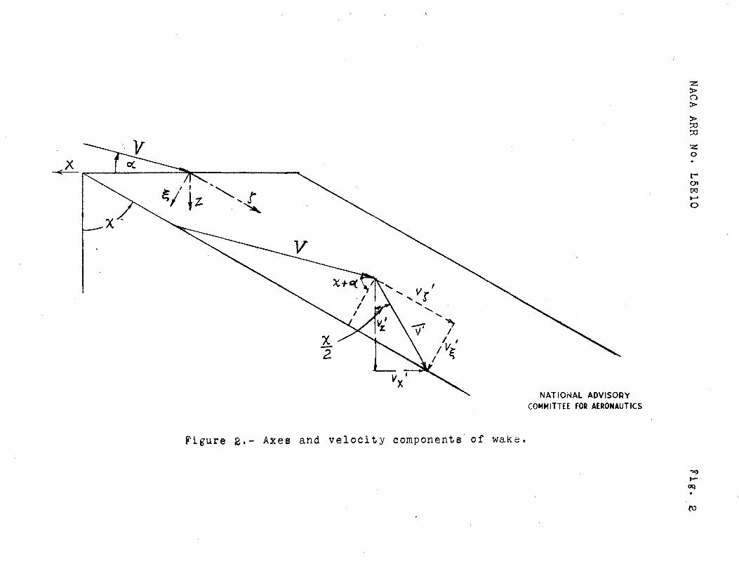
?> rj, t coordinates relative to skewed wake (see fig. 2)
x, j, z coordinates relative to rotor disk (see fig. 2)
v„ normal induced-velocity component at rotor disk
l\. NACA ARR No. L5E10
v„f' , v ' , vJ, v*' Induced-velocity components in J - ultimate wake
u value of induced velocity at center of rotor disk
u-, rate of change of induced velocity along fore-and- aft diameter of rotor at r = 0
u hovering induced velocity
V flight velocity
V resultant velocity at rotor disk in Glauert's formula
a angle of flight path to rotor disk
r distance from hub to position on blade; expressed nondimensionally in terms of rotor radius
\|/ azimuth angle of blade position
T thrust
p air density
A area of rotor disk
C„ thrust coefficient
d.7, line element
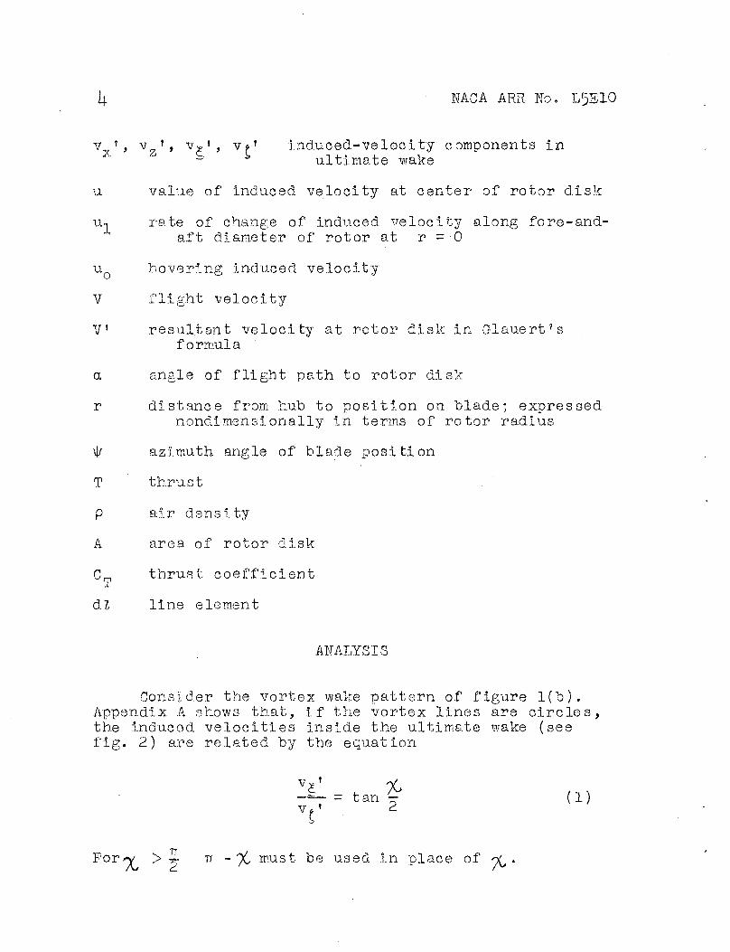
ANALYSIS
Consider the vortex wake pattern of figure 1(b). Appendix A shows that, if the vortex lines are circles, the induced velocities inside the ultimate wake (see fig. 2) are related by the equation
v £f _ . % - t an — (1)
v *' "2
For>v > 5- TT - % must be used in place of o^
NACA ARR No. L5E10
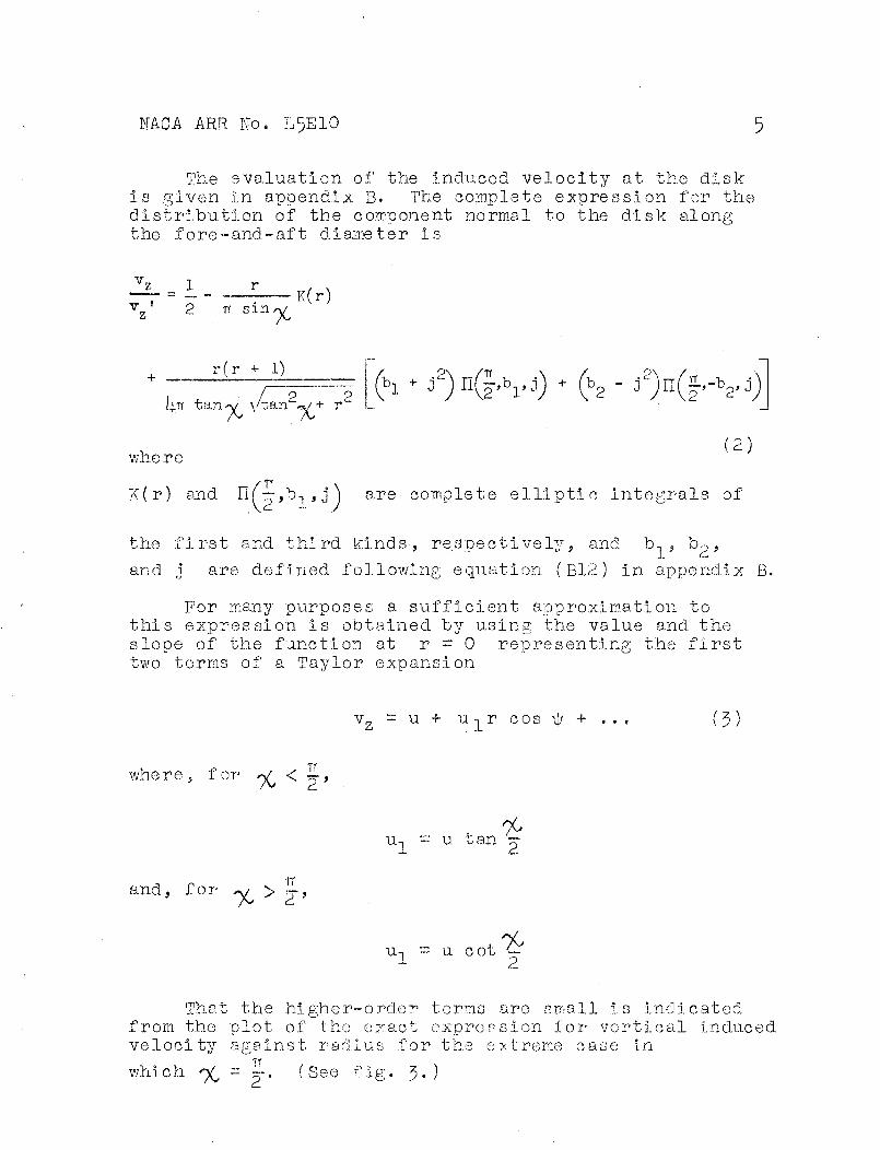
The evaluation of the induced velocity at the disk is given in appendix B. The complete expression for the distribution of the component normal to the disk along the fore-and-aft diameter is
n sin %
K(r)
r(r + 1) / p p
I4.TT tarw \/tanw+ r" [% %
where
(*i • J2) n(?V0 + (b2 - J2)n(|.-VJ
(2)
K(r) and II(—,b-,,j^ are complete elliptic integrals of
the first and third kinds, respectively, and b, , bp ,
and 3 are defined following equation (B12) in appendix B.
For many purposes a sufficient approximation to this expression is obtained by using the value and the slope of the function at r = 0 representing the first two terms of a Taylor expansion
vz = u + u -, r c o s \|/ + ... 3)
IT where, for <y < •*•,
and, for ^/ > ~,
u-, u tan 2
ul = u cot -~ 2
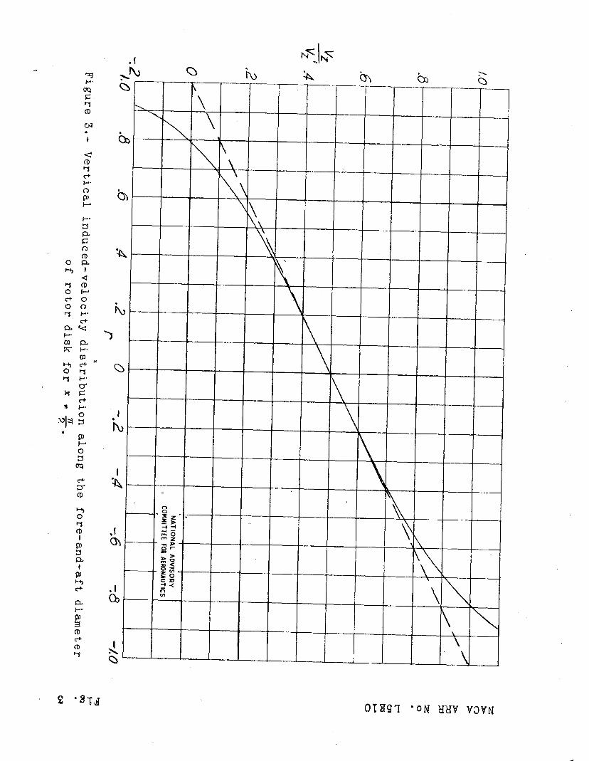
That the higher-order terms are small is indicated from, the plot of the exact expression for vertical induced velocity against radius for the extreme case in
which ^ = =-, (See fig. 3«)

6 NACA ARR No. L5E10
In order to make use of the expressions developed herein, the skew angle yC must be related to other flight parameters. A simple method .is to combine equation (J) with the expressions given by Wald (reference 6), which are based on Glauert's formula for thrust. The induced velocity u in Glauert's formula
T = 2pAuV (h)
is identified with the value at the center of the disk in the present theory.
From the geometry of the wake, it can be seen that
" V cosf-^ + a) (5)
TT Then by using the relations, for «v < —,
V _ , % —7 = tan '— Y 2 (6a)
for %>2 >?,
and
it follows that
= cot^
U = V ' z 2
= Vf s
~2
2 V
tan p
u cos^X, + a)
(6b)
> (7)
(8)
MCA APR No. L5E10 7
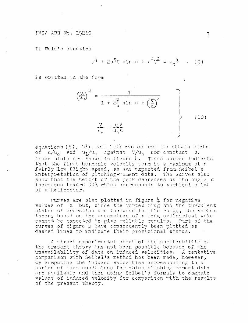
If Wald's equation
u' + 2u^Y sin a + u2V2 u o (9)
Is written In the form
, ii.
VaoJ - 1
•-V
1 + cL— sm a + u a)2
u„ _u_V u„u
(10)
equations (3), (8)5 and (10) can be used to obtain plots of u/u and u-,/u0 against V/u for constant a. u1/u0 These plots are shown in Iigure rpl« « ;e curves Indicate that the first harmonic velocity term Is a maximum at a fairly low flight speed, as was expected from Seibel's interpretation of pitching-moment data. The curves also show that the height of the peak decreases as the angle a Increases toward 9'3°> which corresponds to vertical climb of a helicopter.
values states theory cannot curves
Curves are also plotted in figure l\. for negative a but, since the vortex ring and the turbulent
of operation are included In this range, the vortex based on the assumption of a long cylindrical wake be expected to give reliable results. Part of the of figure li. have consequently been plotted as
dashed, lines to indicate their provisional status.
A direct experimental check of the applicability of the present theory has not been possible because of the unavailability of data on Induced velocities. A tentative comparison with Seibel's method has been made, however, by computing the induced velocities corresponding to a series of test conditions for which pitching-moment data are available and then using Seibel's formula to compute values of induced velocity for comparison with the results of the present theory.

8 FACA ARE No. L5E10
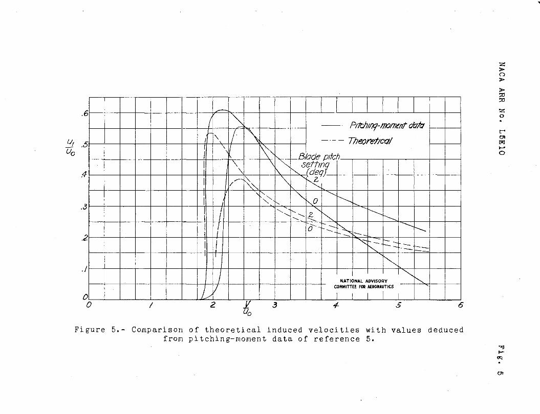
A plot of ui/uo against. V/u0, determined by Seibel's formula and the data of reference 5? is shown in figure 5 for two values of the blade pitch setting. For comparison, the formula for u,/u0 given, in the present paper has been applied /by use of the
formula _ = — -ü-r— ./-:—-) to the same test conditions u0 cos a i/C^
specified by the values of a, Cm, and \i in refer- ence 5« The resulting curves are also plotted in fig- ure 5? which shows that both methods give peaks of the same general appearance. Systematic errors influencing the magnitude of the theoretical peak may be expected from several sources, which include assumptions of
(1) Vortices shed only at blade tips
(2) No contraction of wake
(5) Infinite number of blades
(i|) Slope of induced-velocity function as repre- sentative of front and back inequality of velocity
The net effect of these assumptions appears to be to underestimate the magnitude of u-,. The use of an effective radius smaller than the actual rotor radius would give larger induced velocities for the same total thrust and would tend to show closer agreement between the curves.
In view of the various approximations and possible sources of error Involved in both methods, the qualitative agreement between these two methods is evidence that the most significant factors have been taken into account. Further testing and refinement of analysis should lead to a more detailed understanding of the phenomena involved.
CONCLUSIONS C!
From theoretical considerations, It was concluded that the important variable determining the increase of induced velocity toward the rear of a helicopter rotor
NAGA ARR No. LSElO 9
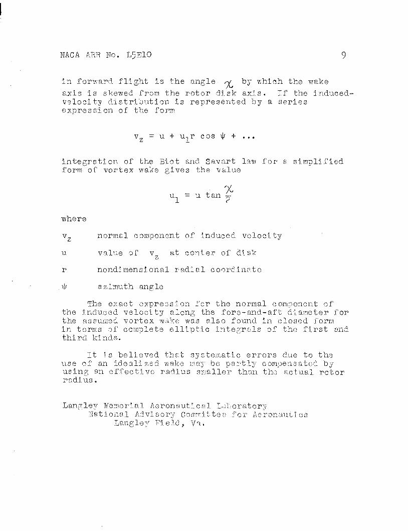
In forward flight is the angle ,y by which the wake axis is skewed from the rotor disk axis. If the induced' velocity distribution is represented by a series expression of the form
v = u + tur cos \|/ + ...
integration of the Blot and Savart law for a simplified form of vortex wake gives the value
un = u tan 2"
where
v normal component of induced velocity
u value of v at center of disk
r nondimensi. onal radial coordinate
ii/ a z I mu t h an g 1 e
The exact expression for the normal component of the induced velocity along the fore-and-aft diameter for the assumed vortex wake was also found, in closed form in terms of complete elliptic integrals of the first and third kinds.
It is believed that systematic errors due to the use of an Idealized wake may be partly compensated by using an effective radius smaller than the actual rotor- radius „
Langley Memorial Aeronautical Laboratory National Advisory Committee for Aeronaut!!
Langley Field,, Va.
10 NACA ARR No. L^ElO
APPENDIX A
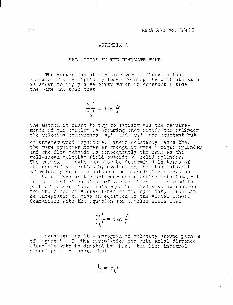
VELOCITIES IN THE ULTIMATE WAKE
The assumption of circular vortex lines on the surface of an elliptic cylinder forming the ultimate wake is shown to imply a velocity which is constant inside the wake and. such that
The method is first to try to satisfy all the require- ments of the problem by assuming that inside the cylinder the velocity components v*.f and v*} are constant but
of undetermined magnitude. Their constancy means that the wake cylinder moves as though It were a rigid cylinder and the flow outside is consequently the same as the well-known velocity field outside a solid cylinder. The vortex strength can then be determined in terms of the assumed, velocities by evaluating the line integral of velocity around a suitable path enclosing a portion of the surface of the cylinder and equating this Integral to the total circulation of vortex lines that thread the path of Integration. This equation yields an expression for the slope of vortex lines on the cylinder, which can be integrated, to give an equation of the vortex lines. Comparison with the equation for circles shows that
-£~ = tan & Y ^
Consider the line integral of velocity around, path A of figure 6. If the circulation per unit axial distance along the wake is denoted by P/s, the line integral around path A shows that
E = v s C

NAGA ARR No. L5E10 11
Now consider the velocity -integral for path B in the £ri-plane of figure 6, Referred to axes fixed, in still air, the velocity potential on the outside surface for the motions in the £rj-plane is
0 - -v ' a cos 6
where v-' refers to the constant velocity inside the d
cylinder»" This potential is the same &s in the flow at the surface of an elliptic cylinder moving through an incompressible fluid that is at rest at infinity. Then
/ v . dl = ^~ de - v.' d£T
= v»' (a + b) sin 0 d9
This integral is equal to the total circulation threaded at B. If the slope of the vortex lines is represented by d£/dG, the number of lines that thread the path B is
s dG
Consequently
Tn d = v,, ' i a + bj sin 9
and, after integration, this equation becomes
v;,. • H
I - - —•>,-- ( & + b) cos 9
The equation of a circular vortex, line, however, is
t ~ -c cos 9

12 NACA ARR No. L5E10
where
Hence,
c = ya2 - b2
V»'S V»1
C a + b
sin % 1 + cos X
= tan ~ 2
It should, be noted that this relation Implies that, inside the ultimate-wake cylinder,
v ' = v - * i

NACA ARR No. L5EIO 13
APPENDIX B
INDUCED«VELOCITY FIELD AT ROTOR DISK
As stated previously, the entire vortex wake is considered to "be an elliptic cylinder composed of a continuous distribution of circular vortex filaments parallel to the rotor disk. (See fig. 7») ->J using the Blot and Savart law, the velocity vector induced by the vortex wake at any point P having coordinates (r,ty ) in the plane of the rotor disk Is given by
2TT co
v = r Vl+m
6»o z-o
r j k
r cosl}/+cos B -z tan'/C -sin 6 -r sin\j,f z
sin 6 cos 9 0;
dz d9
where
P/s axial-vortex strength
r nondimenslonal distance In termer of rotor radius
m = tan /C
i, J, k unit vectors along x, y, and z directions, respectively
p distance from point (r, ty ) to element d8 dz of wake surface
The value of p is given by
p2 = 1+ r2+ z2 (1+ m.2 ) - 2rzm cos ty -2m cos 0 +2r cos("^ - 6 )
P
(Bl)
(B2)
the The vertical component of the induced velocity v7
point (r,ty) can be written from equation (Bl) as
11+ NACA ARR No. L^ElO
'.-? X + m
1+rr
2TT
e=o "z*o
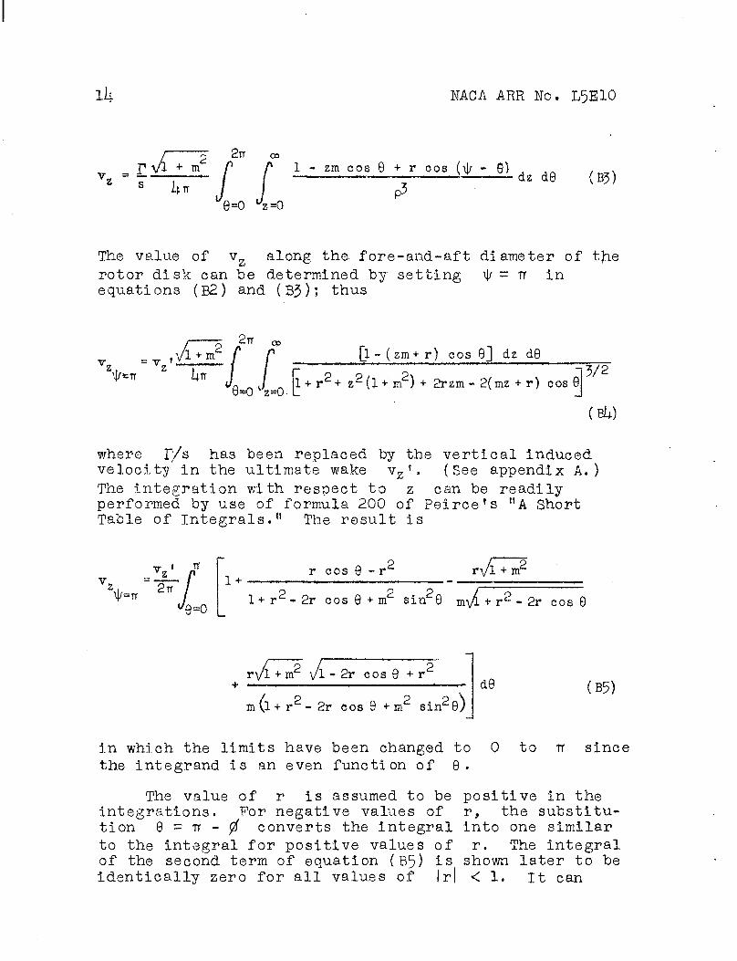
1 - zm cos 9 + r cos (\J/ - 8) dz d9 (B3)
The value of vz along the fore-and-aft diameter of the rotor disk can be determined by setting \j/ = TT in equations (B2) and (BJ); thus
tyfcTf
= v JJL - (zm+ r) cos 9] dz d8
8=0vz=0 l + r2 + z2(l + m ) + 2rzm- 2(mz + r) cos 6
3/2
(Bto
where P/s has been replaced by the vertical induced velocity in the ultimate wake vz'. (See appendix A.) The integration with respect to z can be readily performed by use of formula 200 of Peirce's "A Short Table of Integrals." The result is
>
_ vz p
^8=0
1 + r cos 9 - rc 'Vl + m2
1 + r2 •> 2r cos 9 + m sin 8 m\A + r2 - 2r cos 9
r\A + m2 vl - 2r cos 8 + r •mm ....n». ••••••»•«•i nwiw..—• —in.ni.— *i ••••—
m(l + r - 2r cos 8 + m2 sin29/
d9 (B5)
in which the limits have been changed to 0 to tr the integrand is an even function of 9.
since
The value of r is assumed to be positive in the integrations. For negative values of r, the substitu- tion 9 = TT - 0 converts the integral into one similar to the integral for positive values of r. The integral of the second term of equation (B5) is shown later to be identically zero for all values of |r| < 1. It can
NACA ARR No. L5E10 15
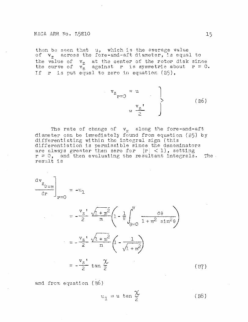
then toe seen that u, which Is the average value of v„ across the fore-and-aft diameter, is equal to the value of v5 the curve of v2
If r Is put equal to zero in equation (B5),
at the center of the rotor disk since against r is symmetric about r = 0.
vr r=0
~ u
v 2
-"»
> (B6)
The rate of change of vz along the fore-and-aft diameter can be immediately found from equation (B5) by differentiating within the integral sign (this differentiation is permissible since the denominators are always greater than zero for |r| •< 1), setting r = 0, and then evaluating the resultant Integrals. The result is
dv
dr = ~Un
v-0
v ' _z_ 2
1 + iri 2
m
JT d(
* ifl=n 1 + m2 sin2 6
vz ' ,/l + m2 / 1 m 1-
yi + m2/
vz' ¥ % — tan 2 (B7)
and from equation (B6)
X u-, = u tan <~ (B8)

16 NACA ARR No. L^EIO
The complete evaluation of equation (B5) is performed most readily by integrating each term separately. The integration is restricted to the case of |r| < 1, that is, within the rotor disk.
The integral of the first term of equation (335) is
evidently TT.
It is now shown that the integral of the second term of equation (B5) is identically zero. By using the conventional transformation
becomes
0, t an ~ = z, the integral
(cos 9 -r)d9 = 2r
1- z2- r (l+z2)] dz
l + r2-2r cos9+m2 sin2 9 ^^ (l + r2)(l + z2)2-2r(l- z^) + i,jn
2Z'
(B9)
The integrand is finite everywhere, approaches zero as z becomes infinite, and is zero and changes sign only at
the point
parts:
z2 = LJUL, 1 + r
Divide the integral into two
J. r z=0
( ) dz =
z=0
( ) dz + ( ) dz (BIO)
If the transformation z = 1 - 1 r _ 1 + r w is applied to the
second integral of the right-hand side of equation (BIO), this integral is seen to be identically equal to the negative of the first integral. The total integral of equation (BIO), or equation (B9), thus is zero. This Integral Is not zero, however, If |rj > 1.

NAGA ARR No. L^EIO 17
The integral of the third term of equation (B5) is equal to
ryl + m' m
2 -TT
9=0
de
1 + r - 2r cos 8
.. = 2rV3- + m' 2
m K(r)
where K(r) is the complete elliptic integral of the first kind.
The integral of the last term of equation (B5) is evaluated by first using the substitution tan — - z,
then separating into partial fractions, and thus obtaining
»TT
5 yl + m2 1 - 2r cos 8 + r2
'9-0 1 - 2r cos 8 + r^ + xcr sin^Q 2„,•2 .de
r(l+ r) P
z=0 2my4n2 + r
where
1 + z2) (k2 + 22
z + m-|
I+^ZEL±Z1 P
z + m> 2
k2 = A-^' U + r,
2
dz
(Bll)
m-, yrr2 + 1 + ^Art2 + r2
r + 1
m \/m^ + 1 - \M~ + r"
2
2 . „2
r + 1
18 NACA ARR No. L^ElO
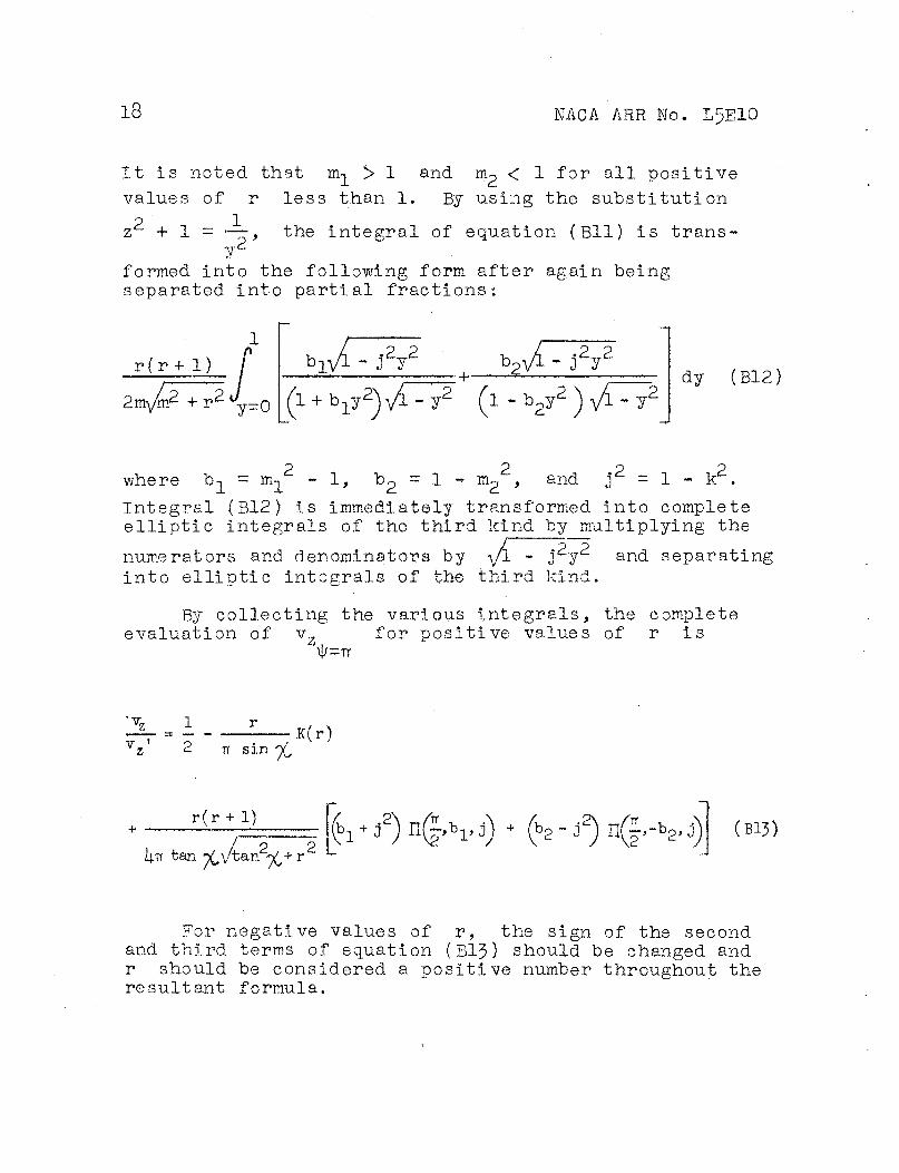
It is noted that m-j_ > 1 and mp < 1 for all positive values of r less than 1. By using the substitution
z2 + 1 y 2'
the integral of equation (Bll) is trans-
formed into the following form after again being separated into partial fractions:
r(r + 1)
2mym2 + r2 -y-0 •J *r\A - 32y2 AA - j2y2
: • + *= '"
(l + b^y2) Vi-y2 (l - b2y2 ) vR dy (B12)
where b-^ = m-^ - 1, b^ = 1 - iru , and j = 1 - k . Integral (B12) Is immediately transformed Into complete elliptic Integrals of the third kind by multiplying the
numerators and denominators by yl - j2y and separating into elliptic integrals of the third kind.
By collecting the various integrals, the complete evaluation of vr for positive values of r is
J\|/=TT
'x,
TT SI n% K(r)
r(r + 1)
i+TT tan V \/ban V + r (bi+ J2) nd'bi> j) + (b2 - J
2) n(g.-*2- J) (B13)
For negative values of r, the sign of the second and third terms of equation (B13) should be changed and r should be considered a positive number throughout the resultant formula.

NACA ARR No. L5E10 19
REFERENCES
1. G-lauert, H.: A General Theory of the Autogyro. P. & M. No. 1111, British A.R.C. , 1928.
2. Wheatley, John B.: An Aerodynamic Analysis of the Autogiro Potor with a Comparison between Calculated and Experimental Results. NACA Rep. No. [j.87, 1934.
3. Nikolsky, Alexander A.: Notes on Helicopter Design Theory. Princeton Univ. Press, 1944 > P« 97«
i|. Seibel, Charles: periodic Aerodynamic Forces on Rotors in Forward Flight. Jour. Aero. Sei., vol. 11, no. !(., Oct. 1944> PP- 339-342.
5. Wheatley, John B., and Bioletti, Carlton: Wind- Tunnel Tests of a 10-Foot-Diameter Gyroplane Rotor. NACA Rep. No. 536, 1935.
6. Wald, Quentin ; A Method for Rapid Estimation of Helicopter Performance. Jour. Aero. Sei., vol. 10, no. Ij-5 April 1943; PP« 131" 135-

SS >
>
> ja ja
o
(a) (b) (c)
Figure 1.- Representation of skewed helical vortex wake by circular and linear vortex wakes.
NATIONAL ADVISORY COMMITTEE FOR AERONAUTICS
"*3
oq
I
> > > •PO
o
a» P3
NATIONAL ADVISORY COMMITTEE FOR AERONAUTICS
Figure Z>- Axes and velocity components' of wake.
•=9
K>
^3 >» O K) N^^
^ a> Co O
CD
On
^>
i
*>.
i
OS -
.1 Cb-
>
\
• 1 >
*> \
J
CD
\
c+
O \\
2 \\ P. C O CD
Y
\ \ o P. Mj 1
< »-» CD \ lo
ci
oto
r \ c+
P. <<
CQ P, \
CO
O i-J \ i-S 1—
c* M H- i o
O |3
oq
\
o o 5 >
m o m 2
-n > -- ö i-
» < £ o C XJ -1 < n w
\
CO i
3 P.
1
\ -
P
—\—^
\
3 0
\ \
CD
\
2 '*M oiagi -ON HHV VOVN

HL
0
Figure 4.- u ui v Induced velocities —- and — against flight speed —. uo o o
6
55 >
r.u \ \
\ \
>
.9 X >\
\ N
\ \ "X>
"X)
\\ X X \
\ \ 2:
.3 ^ V \
\- \ \
o
^ Xi > 0 \ t—
en
.7
\c
\
\ \ P3
\ \ \
o
.6 r V X
^ (deq)
1 d \ \\
.5 -40/
^
V \
\ \v
/ / *? S"~~
—^
^ ̂
f\ b \
.4 1/ / Ni \
/ h 0 ^ fe
\N
^ ^
.3 _'
//
// '/' 2. 0 \ NATIONAL ADVISORY
COMMITTEE FOP AERONAUTICS.
.2 'X / ^
I V TU
I
./ 1/, 60
/ /^
n A y
.6 I / 0ifctiinq-l7)orne/it da fa
~heör&t/ca/ 3 .5 /I r 7 \
/ ^
Pilnrifi nitr.h
A \ \
\ settinq
/^^ \ W
\£
.3
i/
/I N
\ \o / /
\ - x> Z
.2 / |
o"- ^: ^
1 ~-~- - p' ̂ -—
./
1
NATIONAL ADVISORY
0 I COMMITTEE FOR AERONAUTICS
1 1 1 1 1
>
>
>
S3
o
CJI
£
Figure 5.- Comparison of theoretical induced velocities with values deduced from pitching-moment data of reference 5.
^3
oq
a»

NATIONAL ADVISORY COMMITTEE FOR AERONAUTICS
52 > > >
52 o
en
Figure 6.- Integration paths A and B of wake H- oq
o*

NACA ARR No. L5E10 Fig. 7
Figure 7 .• Coordinate system for obtaining induced velocities at rotor disk.
NATIONAL APVISORY COMMITTEE FOR AERONAUTICS.
TF: ISOIÜf05169 (BfCHT) Coleman, Robert Feingold, Arnold
AUTHOR(S)
DIVISION: Aerodynamics (2) SECTION; Wing's and Airfoils (6) CROSS REFERENCES: Airfoils - Aerodynamics (07710);
Helicoptsr rotors - Aerodynamics U9230)
AITD- 7868 ORIG. AGENCY NUMBE
ARP-L5E10
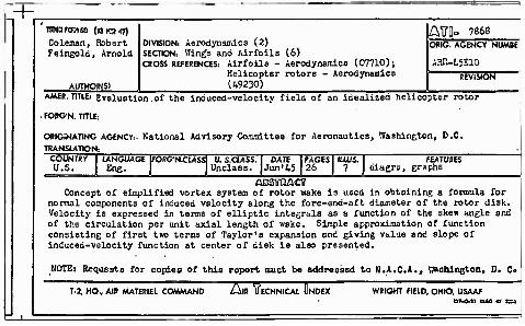
AMER. TITLE: Evsluation of the induced-velocity field of an idealized helicopter rotor
FORG'N. TITLE-.
ORIGINATING AGENCY:. National Advisory Committee for Aeronautics, Washington, D.C. TRANSLATION:
COUNTRY U.S.
LANGUAGE] Eng.
FORG'NrUSSl U. S.CLASS. Unclass.
DATE Jun'45
PAGES 26
IUUS. 7
FEATURES diagrs, graphs
ßBSVQACT Concept of simplified vortex system of rotor wake is used in obtsining a formula for
normal components of induced vslocity along the fore-snd-aft diameter of the rotor disk. Velocity is expressed in terms of elliptic integrals as a function of the ske* angle and of the circulation per unit axial length of wake. Simple approximation of function consisting of first two terms of Taylor's expansion and giving value and slope of induced-velocity function at center of disk is also presented.
NOTE: Requests for copies of this roport muot be addressed to H.A.C.A., Baobington, 0. C»
T-2, HO., AIR AAATERIEL COMAAAND AlR ITECHNICAL QNDEX WRIGHT FIELD. OHIO, USAAF