Embed Size (px)
Citation preview

NAT Box-to-Box High-Availability Support
The NAT Box-to-Box High-Availability Support feature enables network-wide protection by making an IPnetwork more resilient to potential link and router failures at the Network Address Translation (NAT) border.
NAT box-to-box high-availability functionality is achieved when you configure two NAT translators thatreside across different devices as part of a redundancy group (RG) and function as a translation group. Onemember of the translation group acts as an active translator and the other member in the group acts as a standbytranslator. The standby translator takes over as the active translator in the event of any failures to the currentactive translator.
This module provides information about NAT box-to-box high-availability support and describes how toconfigure this feature.
• Finding Feature Information, on page 1• Prerequisites for NAT Box-to-Box High-Availability Support, on page 1• Restrictions for NAT Box-to-Box High-Availability Support, on page 2• Information About NAT Box-to-Box High-Availability Support, on page 2• How to Configure NAT Box-to-Box High-Availability Support, on page 8• Configuration Examples for NAT Box-to-Box High-Availability Support, on page 17• Additional References for NAT Box-to-Box High-Availability Support, on page 19• Feature Information for NAT Box-to-Box High-Availability Support, on page 19
Finding Feature InformationYour software release may not support all the features documented in this module. For the latest caveats andfeature information, see Bug Search Tool and the release notes for your platform and software release. Tofind information about the features documented in this module, and to see a list of the releases in which eachfeature is supported, see the feature information table.
Use Cisco Feature Navigator to find information about platform support and Cisco software image support.To access Cisco Feature Navigator, go to www.cisco.com/go/cfn. An account on Cisco.com is not required.
Prerequisites for NAT Box-to-Box High-Availability Support• Network Address Translation (NAT)-related configurations must be manually configured and theconfiguration must be identical on both devices, and associated to the same redundancy group (RG).
NAT Box-to-Box High-Availability Support1

• RG must be shut down on both peer devices before you configure NAT.
• If devices are already in active/standby states, you must apply any additional configuration changes firston the standby device and then on the active device. To delete NAT configuration rules, you must applythe changes first on the active device and then on the standby device.
Restrictions for NAT Box-to-Box High-Availability Support• Network Address Translation (NAT) configurations with the interface overload option are not supported.• Both application redundancy (using redundancy groups [RGs]) and box-level redundancy cannot beconfigured on the same device.
• RG infrastructure with more than one RG peer is not supported.• Multiprotocol Label Switching (MPLS) with Layer 3 VPN (L3VPN) configuration is not supported.• NAT Virtual Interface (NVI) configuration is not supported.• Only FTP application layer gateway (ALG) is supported. All other ALGs are not high-availability awareand are not expected to work correctly across failovers.
We recommend that you disable all other ALGs using the no ip nat servicecommand, when using this feature.
Note
Information About NAT Box-to-Box High-Availability Support
NAT Box-to-Box High-Availability OverviewThe NAT Box-to-Box High-Availability Support feature enables network-wide protection by making an IPnetwork resilient to potential link and router failures at the Network Address Translation (NAT) border.
The NATBox-to-BoxHigh-Availability Support feature leverages services provided by the redundancy group(RG) infrastructure present on the device to implement the high-availability functionality. The RG infrastructuredefines multiple RGs to which applications can subscribe to and function in an active-standby mode acrossdifferent devices. NAT box-to-box high-availability functionality is achieved when you configure two NATtranslators, residing across different devices, to an RG and function as a translation group. One member ofthe translation group acts as an active translator and the other members of the translation group acts as astandby translator. The active translator is responsible for handling traffic that requires address translation.Additionally, the active translator informs the standby translator about packet flows that are being translated.The standby translator uses this information to create a duplicate translation database that equips the standbytranslator to take over as the active translator in the event of any failures to the active translator. Therefore,the application traffic flow continues unaffected as the translations tables are backed up in a stateful manneracross the active and standby translators.
The NAT Box-to-Box High-Availability Support feature supports active-standby high-availability failoverand asymmetric routing. The NATBox-to-Box High-Availability Support feature supports the following NATfeatures:
• Simple Static NAT configuration
NAT Box-to-Box High-Availability Support2
NAT Box-to-Box High-Availability SupportRestrictions for NAT Box-to-Box High-Availability Support

• Extended Static NAT configuration
• Network Static NAT configuration
• Dynamic NAT and Port Address Translation (PAT) configuration
• NAT inside source, outside source, and inside destination rules
• NAT rules for Virtual Routing and Forwarding (VRF) instances to IP
• NAT rules for VRF-VRF (within same VRF)
Reasons for Active Device FailoverThe following are some of the reasons for the failover of an active device:
• Power loss or reload on the active device.
• Control interface for the redundancy group (RG) is shut down or the link to the interface is down.
• Data interface for the RG is shut down or the link to the interface is down.
• Tracked object failure.
• Protocol keepalive failure.
• The run-time priority of the active device is below the configured threshold. Run-time priority can godown in the following scenarios:
• Traffic interface, that is assigned a Redundancy Interface Identifier (RII) value, is down.
• Object tracked by the RG is down.
• RG on an active device is reloaded using the redundancy application reload group command inprivileged EXEC mode.
• RG on an active device is shut down using the group command in redundancy application configurationmode.
NAT in Active-Standby ModeIn active-standby mode, the redundancy group (RG) that Network Address Translation (NAT) is part ofremains in the standby mode on one device and active on a peer device. NAT in an RG that is in active modetranslates the traffic according the configured translation rules.
NAT does not actively perform any translations on the device where its RG is in the standby mode. In an RG,only one peer is in active mode at a given instance and the other peer is in standby mode. Applications thatbelong to the RG are active only on the device on which the RG is active. On all other devices, applicationsthat belong to the RG are in the standby mode.
In a group of RG peers, only one peer can be active for a specific RG. Currently, the NAT Box-to-BoxHigh-Availability Support feature supports only two peers in an RG and one RG in the RG infrastructure.
Note
NAT Box-to-Box High-Availability Support3
NAT Box-to-Box High-Availability SupportReasons for Active Device Failover

NAT Box-to-Box High-Availability OperationThe following figure illustrates the NAT box-to-box high-availability operation in a LAN-LAN topology.The green color represents an active device and the yellow color represents a standby device.Figure 1: NAT Box-to-Box High Availability Operation
NAT Box-to-Box High-Availability LAN-LAN TopologyIn a LAN-LAN topology, all participating devices are connected to each other through LAN interfaces onboth the inside and the outside. The figure below shows the NAT box-to-box LAN-LAN topology. NetworkAddress Translation (NAT) is in the active-standby mode and the peers are in one redundancy group (RG).All traffic or a subset of this traffic undergoes NAT translation.
Failover is caused by only those failures that the RG infrastructure listens to.Note
NAT Box-to-Box High-Availability Support4
NAT Box-to-Box High-Availability SupportNAT Box-to-Box High-Availability Operation

Figure 2: NAT Box-to-Box High-Availability LAN-LAN Topology
NAT Box-to-Box High-Availability WAN-LAN TopologyIn aWAN-LAN topology, two devices are connected through LAN interfaces on the inside andWAN interfaceson the outside. There is no control on the routing of return traffic received through WAN links. In most cases,WAN links are provided by different service providers. To utilize WAN links to the maximum, configure anexternal device to provide a failover.
In the following figure, inside interfaces are connected to a LAN while outside interfaces are connected to aWAN. The WAN interfaces cannot be made part of a redundancy group (RG) according to the current RGinfrastructure. However, WAN interfaces may be configured in such a way that any failure on the WANinterfaces reduces the priority for the RG that is configured on that node, thereby triggering a failover.
NAT Box-to-Box High-Availability Support5
NAT Box-to-Box High-Availability SupportNAT Box-to-Box High-Availability WAN-LAN Topology
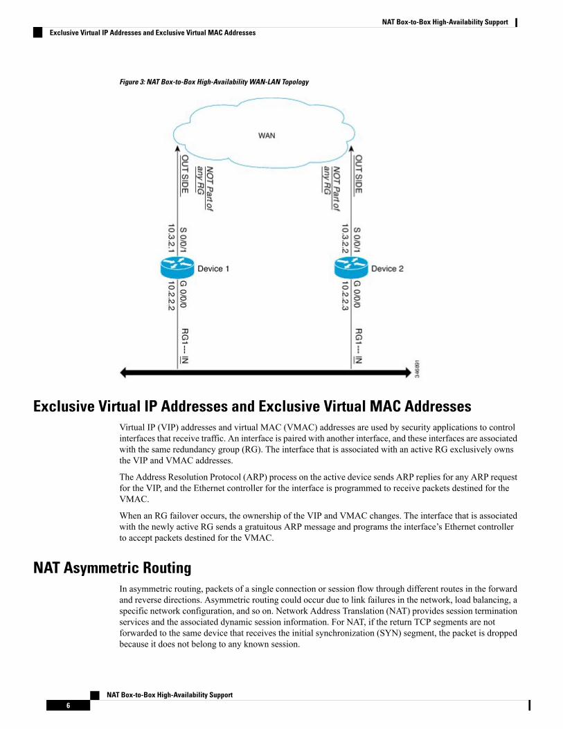
Figure 3: NAT Box-to-Box High-Availability WAN-LAN Topology
Exclusive Virtual IP Addresses and Exclusive Virtual MAC AddressesVirtual IP (VIP) addresses and virtual MAC (VMAC) addresses are used by security applications to controlinterfaces that receive traffic. An interface is paired with another interface, and these interfaces are associatedwith the same redundancy group (RG). The interface that is associated with an active RG exclusively ownsthe VIP and VMAC addresses.
The Address Resolution Protocol (ARP) process on the active device sends ARP replies for any ARP requestfor the VIP, and the Ethernet controller for the interface is programmed to receive packets destined for theVMAC.
When an RG failover occurs, the ownership of the VIP and VMAC changes. The interface that is associatedwith the newly active RG sends a gratuitous ARP message and programs the interface’s Ethernet controllerto accept packets destined for the VMAC.
NAT Asymmetric RoutingIn asymmetric routing, packets of a single connection or session flow through different routes in the forwardand reverse directions. Asymmetric routing could occur due to link failures in the network, load balancing, aspecific network configuration, and so on. Network Address Translation (NAT) provides session terminationservices and the associated dynamic session information. For NAT, if the return TCP segments are notforwarded to the same device that receives the initial synchronization (SYN) segment, the packet is droppedbecause it does not belong to any known session.
NAT Box-to-Box High-Availability Support6
NAT Box-to-Box High-Availability SupportExclusive Virtual IP Addresses and Exclusive Virtual MAC Addresses
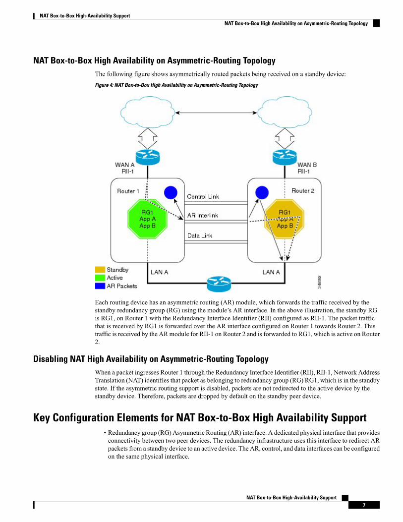
NAT Box-to-Box High Availability on Asymmetric-Routing TopologyThe following figure shows asymmetrically routed packets being received on a standby device:Figure 4: NAT Box-to-Box High Availability on Asymmetric-Routing Topology
Each routing device has an asymmetric routing (AR) module, which forwards the traffic received by thestandby redundancy group (RG) using the module’s AR interface. In the above illustration, the standby RGis RG1, on Router 1 with the Redundancy Interface Identifier (RII) configured as RII-1. The packet trafficthat is received by RG1 is forwarded over the AR interface configured on Router 1 towards Router 2. Thistraffic is received by the ARmodule for RII-1 on Router 2 and is forwarded to RG1, which is active on Router2.
Disabling NAT High Availability on Asymmetric-Routing TopologyWhen a packet ingresses Router 1 through the Redundancy Interface Identifier (RII), RII-1, Network AddressTranslation (NAT) identifies that packet as belonging to redundancy group (RG) RG1, which is in the standbystate. If the asymmetric routing support is disabled, packets are not redirected to the active device by thestandby device. Therefore, packets are dropped by default on the standby peer device.
Key Configuration Elements for NAT Box-to-Box High Availability Support• Redundancy group (RG) Asymmetric Routing (AR) interface: A dedicated physical interface that providesconnectivity between two peer devices. The redundancy infrastructure uses this interface to redirect ARpackets from a standby device to an active device. The AR, control, and data interfaces can be configuredon the same physical interface.
NAT Box-to-Box High-Availability Support7
NAT Box-to-Box High-Availability SupportNAT Box-to-Box High Availability on Asymmetric-Routing Topology

• Redundancy number: A unique identification number for each interface that is part of the RG infrastructure.
• RG priority: A numeric value that you can configure on the active or standby devices to control theswitchover behavior. Each potential fault or error decrements the priority of the active device. The systemswitches over to the standby device when the priority value reaches the configured limit.
• RG control interface: A dedicated physical interface that provides connectivity between the two peerdevices. The redundancy infrastructure uses this interface to exchange control information between thedevices.
• RG data interface: A dedicated physical interface that provides connectivity between two peer devices.This interface is used by the redundancy infrastructure for data information exchange between devices,such as session information for NAT. Control and data interfaces can be configured on the same physicalinterface.
• Virtual IP address and virtual MAC address: The active device owns the virtual IP address and the virtualMAC address. Hosts or servers on the LAN that use the virtual IP address to reach the device which iscurrently in RG active state.
• RG decrement number: The priority value of an RG in local peer is decremented by the specified prioritydecrement number if the interface on which this configuration is applied goes down.
• RG infrastructure: Defines multiple RGs to which applications can subscribe and function in anactive-standby mode across different routing devices. Currently, Network Address Translation (NAT)supports only one RG with an RG ID value of either 1 or 2.
• NAT mapping ID: A numeric value that is attached to all NAT rules that are associated to an RG. Thisvalue must be unique across different NAT rules and must be the same across NAT configurations onactive and standby devices.
How to Configure NAT Box-to-Box High-Availability Support• Perform configurations listed in this section on both the active and standby devices.
• The redundancy group (RG) ID must be the same for both devices.
• A unique redundancy interface identifier (RII) must be configured for each interface on a device that ispart of the RG infrastructure.
• An RG ID and virtual IP address must be configured on each interface on a LAN.
• An RG ID and mapping ID must be configured for each Network Address Translation (NAT) statement.
• After configuring all NAT statements, you must enable RG.
Configuring a Redundancy Application Group
SUMMARY STEPS
1. enable2. configure terminal3. redundancy
NAT Box-to-Box High-Availability Support8
NAT Box-to-Box High-Availability SupportHow to Configure NAT Box-to-Box High-Availability Support

4. application redundancy5. group id6. name group-name7. shutdown8. priority value [failover threshold value]9. preempt10. track object-number {decrement value | shutdown}11. end
DETAILED STEPS
PurposeCommand or Action
Enables privileged EXEC mode.enableStep 1
Example: • Enter your password if prompted.Device> enable
Enters global configuration mode.configure terminal
Example:
Step 2
Device# configure terminal
Enters redundancy configuration mode.redundancy
Example:
Step 3
Device(config)# redundancy
Enters redundancy application configuration mode.application redundancy
Example:
Step 4
Device(config-red)# application redundancy
Enters redundancy application group configuration mode.group id
Example:
Step 5
Device(config-red-app)# group 1
(Optional) Specifies an optional alias for the protocolinstance.
name group-name
Example:
Step 6
Device(config-red-app-grp)# name group1
(Optional) Shuts down a redundancy group manually.shutdown
Example:
Step 7
Device(config-red-app-grp)# shutdown
(Optional) Specifies the initial priority and failoverthreshold for a redundancy group.
priority value [failover threshold value]
Example:
Step 8
Device(config-red-app-grp)# priority 100 failoverthreshold 50
NAT Box-to-Box High-Availability Support9
NAT Box-to-Box High-Availability SupportConfiguring a Redundancy Application Group

PurposeCommand or Action
Enables preemption on the group and enables the standbydevice to preempt the active device regardless of thepriority.
preempt
Example:Device(config-red-app-grp)# preempt
Step 9
Specifies the priority value of a redundancy group that willbe decremented if an event occurs.
track object-number {decrement value | shutdown}
Example:
Step 10
Device(config-red-app-grp)# track 200 decrement200
Exits redundancy application group configuration modeand enters privileged EXEC mode.
end
Example:
Step 11
Device(config-red-app-grp)# end
Configuring Data, Control, and Asymmetric Routing InterfacesIn this task, you configure the following redundancy group (RG) elements:
• The interface that is used as the control interface.
• The interface that is used as the data interface.
• The interface that is used for asymmetric routing. This is an optional task. Perform this task only if youare configuring asymmetric routing for Network Address Translation (NAT).
Asymmetric routing, data, and control must be configured on separate interfaces for zone-based firewall.However, for Network Address Translation (NAT), asymmetric routing, data, and control can be configuredon the same interface.
Note
SUMMARY STEPS
1. enable2. configure terminal3. redundancy4. application redundancy5. group id6. data interface-type interface-number7. control interface-type interface-number protocol id8. timers delay seconds [reload seconds]9. asymmetric-routing interface type number10. asymmetric-routing always-divert enable11. end
NAT Box-to-Box High-Availability Support10
NAT Box-to-Box High-Availability SupportConfiguring Data, Control, and Asymmetric Routing Interfaces

DETAILED STEPS
PurposeCommand or Action
Enables privileged EXEC mode.enable
Example:
Step 1
• Enter your password if prompted.Device> enable
Enters global configuration mode.configure terminal
Example:
Step 2
Device# configure terminal
Enters redundancy configuration mode.redundancy
Example:
Step 3
Device(config)# redundancy
Configures application redundancy and enters redundancyapplication configuration mode.
application redundancy
Example:
Step 4
Device(config-red)# application redundancy
Configures a redundancy group (RG) and entersredundancy application group configuration mode.
group id
Example:
Step 5
Device(config-red-app)# group 1
Specifies the data interface that is used by the RG.data interface-type interface-number
Example:
Step 6
Device(config-red-app-grp)# data GigabitEthernet0/0/1
Specifies the control interface that is used by the RG.control interface-type interface-number protocol id
Example:
Step 7
• The control interface is also associated with aninstance of the control interface protocol.Device(config-red-app-grp)# control
GigabitEthernet 1/0/0 protocol 1
Specifies the time required for an RG to delay rolenegotiations that start after a fault occurs or the system isreloaded.
timers delay seconds [reload seconds]
Example:Device(config-red-app-grp)# timers delay 100reload 400
Step 8
Specifies the asymmetric routing interface that is used bythe RG.
asymmetric-routing interface type number
Example:
Step 9
Device(config-red-app-grp)# asymmetric-routinginterface GigabitEthernet 0/1/1
Always diverts packets received from the standby RG tothe active RG.
asymmetric-routing always-divert enable
Example:
Step 10
Device(config-red-app-grp)# asymmetric-routingalways-divert enable
NAT Box-to-Box High-Availability Support11
NAT Box-to-Box High-Availability SupportConfiguring Data, Control, and Asymmetric Routing Interfaces

PurposeCommand or Action
Exits redundancy application group configuration modeand enters privileged EXEC mode.
end
Example:
Step 11
Device(config-red-app-grp)# end
Enabling Data, Control and Asymmetric Routing Interfaces
SUMMARY STEPS
1. enable2. configure terminal3. interface type number4. ip address ip-address mask5. no shutdown6. exit7. interface type number8. ip address ip-address mask9. no shutdown10. exit11. interface type number12. ip address ip-address mask13. no shutdown14. exit
DETAILED STEPS
PurposeCommand or Action
Enables privileged EXEC mode.enable
Example:
Step 1
• Enter your password if prompted.Device> enable
Enters global configuration mode.configure terminal
Example:
Step 2
Device# configure terminal
Enters interface configuration mode for the data interface.interface type number
Example:
Step 3
Device(config)# interface GigabitEthernet 0/0/1
Assigns an IP address for the data interface.ip address ip-address mask
Example:
Step 4
Device(config-if)# ip address 10.2.3.2255.255.255.0
NAT Box-to-Box High-Availability Support12
NAT Box-to-Box High-Availability SupportEnabling Data, Control and Asymmetric Routing Interfaces

PurposeCommand or Action
Enables the interface.no shutdown
Example:
Step 5
Device(config-if)# no shutdown
Exits interface configuration mode and enters globalconfiguration mode.
exit
Example:
Step 6
Device(config-if)# exit
Enters interface configuration mode for the controlinterface.
interface type number
Example:
Step 7
Device(config)# interface gigabitethernet 1/0/0
Assigns an IP address to the control interface.ip address ip-address mask
Example:
Step 8
Device(config-if)# ip address 10.10.2.5255.255.255.255.0
Enables the interface.no shutdown
Example:
Step 9
Device(config-if)# no shutdown
Exits interface configuration mode and enters globalconfiguration mode.
exit
Example:
Step 10
Device(config-if)# exit
(Optional) Enters interface configuration mode for theasymmetric routing (AR) interface.
interface type number
Example:
Step 11
Device(config)# interface gigabitethernet 0/1/1
(Optional) Assigns an IP address to the AR interface.ip address ip-address mask
Example:
Step 12
Device(config-if)# ip address 10.5.1.5255.255.255.255.0
(Optional) Enables the interface.no shutdown
Example:
Step 13
Device(config-if)# no shutdown
(Optional) Exits interface configuration mode and entersglobal configuration mode.
exit
Example:
Step 14
Device(config-if)# exit
NAT Box-to-Box High-Availability Support13
NAT Box-to-Box High-Availability SupportEnabling Data, Control and Asymmetric Routing Interfaces

Configuring NAT Box-to-Box Interface RedundancyPerform this task on the active and standby devices in the redundancy group to configure the Network AddressTranslation (NAT) box-to-box high-availability support.
SUMMARY STEPS
1. enable2. configure terminal3. interface type number4. ip address ip-address mask5. ip nat inside6. redundancy rii id7. redundancy group id ip virtual-ip [exclusive] [decrement value]8. exit9. interface type number10. ip address ip-address mask11. ip nat outside12. redundancy rii id [decrement number]13. redundancy group id ip virtual-ip [exclusive] [decrement value]14. exit15. ip nat inside source static local-ip global-ip [redundancy rg-id mapping-id map-id]16. end
DETAILED STEPS
PurposeCommand or Action
Enables privileged EXEC mode.enableStep 1
Example: • Enter your password if prompted.Device> enable
Enters global configuration mode.configure terminal
Example:
Step 2
Device# configure terminal
Configures an interface and enters interface configurationmode.
interface type number
Example:
Step 3
Device(config)# interface gigabitethernet 2/0/2
Assigns a virtual IP (VIP) address on the interface.ip address ip-address mask
Example:
Step 4
Device(config-if)# ip address 192.168.1.27255.255.255.0
Designates that traffic originating from the interface issubject to Network Address Translation (NAT).
ip nat inside
Example:
Step 5
NAT Box-to-Box High-Availability Support14
NAT Box-to-Box High-Availability SupportConfiguring NAT Box-to-Box Interface Redundancy

PurposeCommand or ActionDevice(config-if)# ip nat inside
Configures a Redundancy Interface Identifier (RII) forredundancy group-protected traffic interfaces.
redundancy rii id
Example:
Step 6
Device(config-if)# redundancy rii 100
Enables the redundancy group (RG) traffic interfaceconfiguration.
redundancy group id ip virtual-ip [exclusive][decrement value]
Example:
Step 7
Device(config-if)# redundancy group 1 ip192.168.1.20 exclusive decrement 100
Exits interface configuration mode and enters globalconfiguration mode.
exit
Example:
Step 8
Device(config-if)# exit
Configures an interface and enters interface configurationmode.
interface type number
Example:
Step 9
Device(config)# interface gigabitethernet 0/0/0
Assigns a virtual IP (VIP) address on the interface.ip address ip-address mask
Example:
Step 10
Device(config-if)# ip address 192.168.5.54255.255.255.255.0
Designates that traffic destined for the interface is subjectto NAT.
ip nat outside
Example:
Step 11
Device(config-if)# ip nat outside
Configures an RII for redundancy group-protected trafficinterfaces.
redundancy rii id [decrement number]
Example:
Step 12
Device(config-if)# redundancy rii 101
Enables the redundancy group (RG) traffic interfaceconfiguration and specifies the decrement value number
redundancy group id ip virtual-ip [exclusive][decrement value]
Step 13
that is decremented from the priority when the state of theinterface goes down.Example:
Device(config-if)# redundancy group 1 ip192.168.5.10 exclusive decrement 100
Exits interface configuration mode and enters globalconfiguration mode.
exit
Example:
Step 14
Device(config-if)# exit
Enables NAT redundancy of the inside source andassociates the mapping ID to NAT high-availabilityredundancy.
ip nat inside source static local-ip global-ip[redundancy rg-id mapping-id map-id]
Example:
Step 15
NAT Box-to-Box High-Availability Support15
NAT Box-to-Box High-Availability SupportConfiguring NAT Box-to-Box Interface Redundancy

PurposeCommand or ActionDevice(config)# ip nat inside source static10.2.2.1 10.3.4.6 redundancy 1 mapping-id 120
Exits interface configuration mode and enters privilegedEXEC mode.
end
Example:
Step 16
Device(config-if)# end
ConfiguringAsymmetricRoutingforNATBox-to-BoxHigh-AvailabilitySupportPerform this task on the active and standby devices in the redundancy group to configure asymmetric routingsupport on Network Address Translation (NAT) Box-to-Box high availability.
SUMMARY STEPS
1. enable2. configure terminal3. interface type number4. ip address ip-address mask5. ip nat outside6. redundancy rii id [decrement number]7. redundancy asymmetric routing enable8. exit9. ip nat inside source static local-ip global-ip [redundancy RG-id mapping-id map-id]10. end
DETAILED STEPS
PurposeCommand or Action
Enables privileged EXEC mode.enableStep 1
Example: • Enter your password if prompted.Device> enable
Enters global configuration mode.configure terminal
Example:
Step 2
Device# configure terminal
Configures an interface and enters interface configurationmode.
interface type number
Example:
Step 3
Device(config)# interface serial 0/0/1
Assigns a virtual IP (VIP) address on the interface.ip address ip-address mask
Example:
Step 4
Device(config-if)# ip address 192.168.1.27255.255.255.0
NAT Box-to-Box High-Availability Support16
NAT Box-to-Box High-Availability SupportConfiguring Asymmetric Routing for NAT Box-to-Box High-Availability Support

PurposeCommand or Action
Designates that traffic destined for the interface is subjectto Network Address Translation (NAT).
ip nat outside
Example:
Step 5
Device(config-if)# ip nat outside
Configures a Redundancy Interface Identifier (RII) forredundancy group-protected traffic interfaces.
redundancy rii id [decrement number]
Example:
Step 6
Device(config-if)# redundancy rii 101
Establishes an asymmetric flow diversion tunnel for eachredundancy group (RG).
redundancy asymmetric routing enable
Example:
Step 7
Device(config-if)# redundancy asymmetric-routingenable
Exits interface configuration mode and enters globalconfiguration mode.
exit
Example:
Step 8
Device(config-if)# exit
Enables NAT redundancy of the inside source andassociates the mapping ID to NAT high-availabilityredundancy.
ip nat inside source static local-ip global-ip[redundancy RG-id mapping-id map-id]
Example:
Step 9
Device(config)# ip nat inside source static10.2.2.1 10.3.4.6 redundancy 1 mapping-id 120
Exits interface configuration mode and enters privilegedEXEC mode.
end
Example:
Step 10
Device(config-if)# end
Configuration Examples for NAT Box-to-Box High-AvailabilitySupport
Example: Configuring a Redundancy Application GroupThe following example shows how to configure a redundancy group named group1 with priority and preemptattributes:Device# configure terminalDevice(config)# redundancyDevice(config-red)# application redundancyDevice(config-red-app)# group 1Device(config-red-app-grp)# name group1Device(config-red-app-grp)# priority 100 failover-threshold 50Device(config-red-app-grp)# preemptDevice(config-red-app-grp)# track 200 decrement 200Device(config-red-app-grp)# end
NAT Box-to-Box High-Availability Support17
NAT Box-to-Box High-Availability SupportConfiguration Examples for NAT Box-to-Box High-Availability Support

Example: Configuring Data, Control, and Asymmetric Routing InterfacesDevice# configure terminalDevice(config)# redundancyDevice(config-red)# application redundancyDevice(config-red-app)# group 1Device(config-red-app-grp)# data GigabitEthernet 0/0/1Device(config-red-app-grp)# control GigabitEthernet 1/0/0 protocol 1Device(config-red-app-grp)# timers delay 100 reload 400Device(config-red-app-grp)# asymmetric-routing interface GigabitEthernet 0/1/1Device(config-red-app-grp)# asymmetric-routing always-divert enableDevice(config-red-app-grp)# end
Example: Enabling Data, Control and Asymmetric Routing InterfacesDevice# configure terminalDevice(config)# interface GigabitEthernet 0/0/1Device(config-if)# ip address 10.2.3.2 255.255.255.0Device(config-if)# no shutdownDevice(config-if)# exitDevice(config)# interface Gigabitethernet 1/0/0Device(config-if)# ip address 10.10.2.5 255.255.255.255.0Device(config-if)# no shutdownDevice(config-if)# exitDevice(config)# interface Gigabitethernet 0/1/1Device(config-if)# ip address 10.5.1.5 255.255.255.255.0Device(config-if)# no shutdownDevice(config-if)# end
Example: Configuring a NAT Box-to-Box High-Availability Support
Device> enableDevice# configure terminalDevice(config)# interface gigabitethernet 2/0/2Device(config-if)# ip address 192.168.1.27 255.255.255.0Device(config-if)# ip nat insideDevice(config-if)# redundancy rii 100Device(config-if)# redundancy group 1 ip 192.168.1.20 exclusive decrement 100Device(config-if)# exitDevice(config)# interface gigabitethernet 0/0/0Device(config-if)# ip address 192.168.5.54 255.255.255.255.0Device(config-if)# ip nat outsideDevice(config-if)# redundancy rii 101Device(config-if)# redundancy group 1 ip 192.168.5.10 exclusive decrement 100Device(config-if)# exitDevice(config)# ip nat inside source static 10.2.2.1 10.3.4.6 redundancy 1 mapping-id 120Device(config-if)# end
NAT Box-to-Box High-Availability Support18
NAT Box-to-Box High-Availability SupportExample: Configuring Data, Control, and Asymmetric Routing Interfaces

Example:ConfiguringAsymmetricRoutingforNATBox-to-BoxHigh-AvailabilitySupport
Device> enableDevice# configure terminalDevice(config)# interface serial 0/0/1Device(config-if)# ip address 192.168.1.27 255.255.255.0Device(config-if)# ip nat outsideDevice(config-if)# redundancy rii 101Device(config-if)# exitDevice(config)# ip nat inside source static 10.2.2.1 10.3.4.6 redundancy 1 mapping-id 120Device(config-if)# end
Additional References for NAT Box-to-Box High-AvailabilitySupport
Related Documents
Document TitleRelated Topic
Cisco IOS Master Command List, All ReleasesCisco IOS commands
Cisco IOS IP Addressing Services CommandReference
NAT commands
Technical Assistance
LinkDescription
http://www.cisco.com/cisco/web/support/index.htmlTheCisco Support andDocumentationwebsite providesonline resources to download documentation, software,and tools. Use these resources to install and configurethe software and to troubleshoot and resolve technicalissues with Cisco products and technologies. Access tomost tools on the Cisco Support and Documentationwebsite requires a Cisco.com user ID and password.
Feature Information for NAT Box-to-Box High-AvailabilitySupport
The following table provides release information about the feature or features described in this module. Thistable lists only the software release that introduced support for a given feature in a given software releasetrain. Unless noted otherwise, subsequent releases of that software release train also support that feature.
NAT Box-to-Box High-Availability Support19
NAT Box-to-Box High-Availability SupportExample: Configuring Asymmetric Routing for NAT Box-to-Box High-Availability Support

Use Cisco Feature Navigator to find information about platform support and Cisco software image support.To access Cisco Feature Navigator, go to www.cisco.com/go/cfn. An account on Cisco.com is not required.
Table 1: Feature Information for NAT Box-to-Box High Availability Support
Feature Configuration InformationReleasesFeature Name
NAT Box-to-Box High-Availability Supportfeature makes an IP network more resilient topotential link and routing device failures at theNetwork Address Translation (NAT) border.
NAT box-to-box high-availability functionalityis achieved when you configure two NATtranslators that reside across different devicesas part of a redundancy group (RG) and functionas a translation group. One member of thetranslation group acts as an active translator andthe other member in the group acts as a standbytranslator. The standby translator takes over asthe active translator in the event of any failuresto the current active translator.
The following commands were introduced ormodified: ip nat inside source, ip nat outsidesource, show ip nat redundancy, show ip nattranslations redundancy, show redundancyapplication group.
15.3(2)TNATBox-to-BoxHighAvailabilitySupport
NAT Box-to-Box High-Availability Support20
NAT Box-to-Box High-Availability SupportFeature Information for NAT Box-to-Box High-Availability Support