Embed Size (px)
DESCRIPTION
A liquid ring vacuum pump compresses gases using a auxiliary liquid (normal water ) as a liquid compressant as sealing liquid & cooling liquid
Citation preview

CHAPTER 2.
TWO-STAGE VACUUM PUMP


ii
WARNING
Do not operate until pump is initially primed and connected to constant supply of clean compressant liquid. IF RUN DRY, PUMPWILL BE DAMAGED. Always use strainer to prevent sand and scale from entering the pump with liquid.
Certain operating conditions in combination with water hardness may result in excessive lime deposits within the pump, causingit to bind. Should this condition be evident, flush pump with a solvent at regular intervals.
This pump has been drained and flushed with a water-soluble preservative oil prior to shipment. After pump has been in service,do not store without draining as specified within this Bulletin. Pump can be damaged by freezing.
USE CAUTION when removing inlet screens. Any foreign material on screen may fall into pump and cause extensive damage atstart-up.
Base must be mounted to a leveled foundation and final coupling alignment done during installation. (Refer to Bulletin No. 642,Installation Instructions, Nash Vacuum Pumps and Compressors.)
NOTICE
SERVICE AND PARTS
SERVICE AND PARTS FOR NASH PUMPS ARE ASSURED THROUGH A WORLDWIDE NETWORK OF SALES AND SERVICEOFFICES LISTED ON THE BACK COVER OF THIS BULLETIN. ANY REQUEST FOR INFORMATION, SERVICE AND PARTSSHOULD BE DIRECTED TO THE NEAREST NASH FIELD OFFICE.
WHEN ORDERING REPLACEMENT AND SPARE PARTS, TEST NUMBERS AND PUMP SIZES MUST BE PROVIDED. Testnumber and pump size are located on nameplate fastened to body of pump. If nameplate has been destroyed, test number will befound stamped on the body. Parts must be identified by index number and name. Refer to pump exploded view and legend, foundwithin this Bulletin.
If the location of the nearest office is unknown, information may be secured directly from Nash U.S., Trumbull, Connecticut 06611-1330, U.S.A. Telephone number is 203-459-3900, Fax No. 203-459-3988.
WARRANTY
Nash warrants that (i) the goods will be of the kind described on its acceptance of Buyer’s order as modified by any subsequentmutual agreement of the parties, (ii) it will convey to Buyer good title to such goods, (iii) such goods will be delivered free of anylawful security interest or lien or encumbrances unknown to Buyer, and (iv) such goods will be of merchantable quality and freefrom defects in material or workmanship under normal use and prescribed maintenance for a period of two (2) years from the dateof shipment. The warranties specified shall also extend to goods manufactured by others and supplied by Nash, unless suchgoods have been separately stated and quoted by Nash, in which case only the warranties in clauses (i), (ii), and (iii) shall apply.NASH MAKES NO WARRANTY, EXPRESS OR IMPLIED, AS TO THE MERCHANTABILITY OF GOODS MANUFACTURED BYITS SUPPLIERS AND SEPARATELY STATED AND QUOTED HEREIN. Nash’s warranty in clause (iv) above shall not apply togoods of standard construction when handling corrosive gases or using corrosive liquid compressants nor will clause (iv) apply togoods which have been damaged, altered or negligently maintained after delivery. Buyer’s exclusive remedy for Nash’s breach ofthe warranties set forth in clauses (i), (ii) and (iii) above shall be the replacement by Nash of non-conforming goods with conform-ing goods, without extra costs to Buyer, F.O.B. point of manufacture, with transportation prepaid to U.S. destination or domesticport, and Buyer’s exclusive remedy for Nash’s breach of the warranty contained in clause (iv) above shall be the repair by Nashwithout charge, or the furnishing by Nash, F.O.B. point of manufacture, with transportation prepaid to U.S. destination or domesticport of a part or item of equipment to replace any part or item of equipment which is proved to have been defective; provided that(i) Buyer shall have notified Nash of any such breach not later than 10 days after the expiration of two (2) years from the date ofshipment of the goods, and that (ii) Nash shall have the option of requiring the return of any defective material transportationprepaid to establish a claim. Nash shall in no event be liable for Buyer’s manufacturing costs, lost profits, goodwill, expenses, orany other consequential or incidental damages resulting from a breach by Nash of any warranty. THERE ARE NO OTHERWARRANTIES, EXPRESS OR IMPLIED, WHICH EXTEND BEYOND THE WARRANTIES SET FORTH HEREIN.
The Name "Nash" used in this bulletin is a RegisteredTrademark of the Nash Engineering Company
© COPYRIGHT 1997The Nash Engineering Co.
Lithographed in U.S.A.

TABLE OF CONTENTS
Section 1. Description
1-1 About this Bulletin ............................................................................................................................... 1
1-2 How the Nash Vacuum Pump Works ................................................................................................... 1
Section 2. Operation
2-1 Preparation for Intial Start-Up ............................................................................................................. 3
2-2 Liquid Compressant (Seal Water) ................................................................................................... 3
2-3 Draining and Flushing ..................................................................................................................... 3
2-4 Preliminary Inspection .................................................................................................................... 3
2-5 Start-Up and Operating Checks ......................................................................................................... 4
Section 3. Troubleshooting
3-1 Locating Troubles................................................................................................................................. 5
Section 4. Preventive Maintenance
4-1 Periodic Maintenance ........................................................................................................................... 5
4-2 Six Month Intervals ......................................................................................................................... 5
4-3 Twelve Month Intervals ................................................................................................................... 5
4-4 Bearing Lubrication......................................................................................................................... 5
4-5 Stuffing Box Packing ........................................................................................................................... 6
4-6 Shutdown Periods................................................................................................................................. 7
Section 5 Disassembly, Inspection and Reassembly
5-1 Dismantling Pump ............................................................................................................................... 9
5-2 Disassembling Fixed Bearing End ................................................................................................ 10
5-3 Disassembling Floating Bearing End ............................................................................................ 12
5-4 Removing Rotor and Shaft Assembly ...........................................................................................12
5-5 Removing Body/Floating Bearing End Head and Cone Assembly .............................................. 12
5-6 Removing Rotor from Shaft .......................................................................................................... 13
5-7 Removing Cone from Head .......................................................................................................... 13
5-8 Inspection of Disassembled Parts....................................................................................................... 13
5-9 Cones ............................................................................................................................................. 13
5-10 Rotor .............................................................................................................................................. 14
iii

TABLE OF CONTENTS (Continued)
5-11 Shaft .............................................................................................................................................. 14
5-12 Reassembling Pump ...........................................................................................................................14
5-13 Reassembling Rotor and Shaft ...................................................................................................... 14
5-14 Installing Cone in Head .................................................................................................................15
5-15 Installing Body onto Floating Bearing End Head and Cone Assembly........................................ 16
5-16 Installing Rotor and Shaft Assembly ............................................................................................ 16
5-17 Installing Fixed Bearing End Head and Cone Assembly on Body ...............................................16
5-18 Assembling Floating and fixed Bearing Ends ...............................................................................16
5-19 Installing Fixed Bearing ................................................................................................................ 16
5-20 Installing Floating Bearing (119) .................................................................................................. 18
5-21 Setting End Travel and Final Assembly ........................................................................................ 19
5-22 Bearing Lubrication.......................................................................................................................20
LIST OF ILLUSTRATIONS
Figure No.
1-1 Functional Elements of TC Two-Stage Vacuum Pump ........................................................................ 1
1-2 First-stage Liquid Compressant and Air Flow .....................................................................................2
2-1 Typical Piping Connections .................................................................................................................3
4-1 Removing Stuffing Box Packing .........................................................................................................7
4-2 Stuffing Box Lantern Gland Puller ...................................................................................................... 7
4-3 Packing Stuffing Boxes ........................................................................................................................ 8
5-1 Removing Fixed Bearing Bracket ...................................................................................................... 10
5-2 Bearing Pulling Tools .........................................................................................................................11
5-3 Pulling Bearing .................................................................................................................................. 11
5-4 Removing Idle End Head and Cone assembly ...................................................................................12
5-5 Loosening Cone Screws .....................................................................................................................13
5-6 Checking Cone for Wear .................................................................................................................... 13
5-7 Pressing Rotor onto Shaft .................................................................................................................. 14
5-8 Installing Rotor and Shaft Assembly .................................................................................................15
5-9 Tapered Roller Bearing Assembly Exploded View ............................................................................ 16
5-10 Installing Fixed Bearing .....................................................................................................................17
5-11 Measuring Bearing Roller-Cap Clearance .........................................................................................18
iv
LIST OF ILLUSTRATIONS (continued)
5-12 Measuring End Travel at Floating Bearing End ................................................................................. 18
5-13 End Travel Check Setup at Fixed Bearing End .................................................................................. 19
5-14 Measuring Shim Gap ......................................................................................................................... 20
5-15 Typical Nash TC Two-Stage Vacuum Pump, Exploded View ............................................................ 22
LIST OF TABLES
Table No.
4-1 General Grease Specifications .............................................................................................................. 7
5-1 Pump Data ............................................................................................................................................ 9
5-2 Approximate Weights of Parts ........................................................................................................... 10
v

SECTION 1DESCRIPTION
1
FLOATING BEARINGEND HEAD
AIR INLET
FLOATINGBEARING END
CONE
FIRST STAGEROTOR
SECOND STAGEROTOR
FIXED BEARINGBRACKET
AIRDISCHARGE
FIXED BEARINGEND HEAD
BODY
FLOATING BEARINGBRACKET
DRIVESHAFT
FIXED BEARINGEND CONE
Figure 1-1. Functional Elements of TC Two-Stage Vacuum Pump
1-1 ABOUT THIS BULLETIN
This bulletin contains information for owners andoperators of the Nash Two-Stage Vacuum Pump, TC. Thisinformation includes a description of how to operate andmaintain these vacuum pumps.
NoteFor installation information refer to Bulletin No.642, Installation Instructions, Nash VacuumPumps and Compressors.
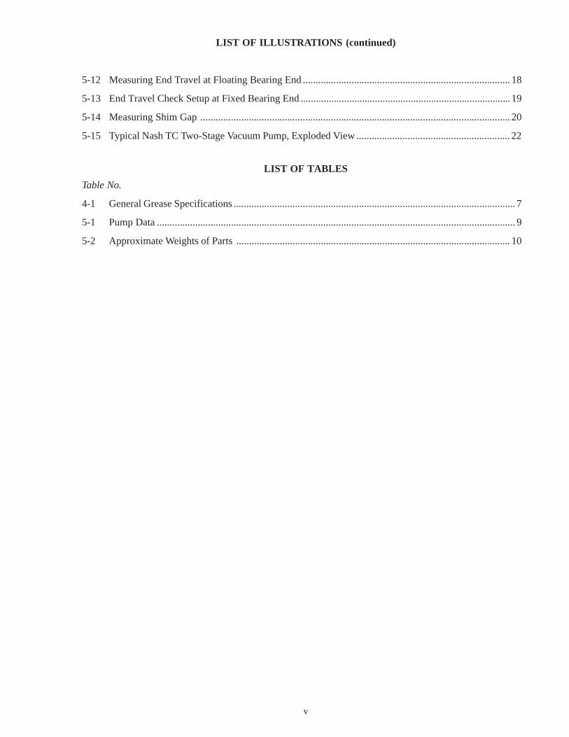
1-2 HOW THE NASH VACUUM PUMPWORKS
The main functional assemblies of the Nash TC two-stagevacuum pump are shown in Figure 1-1. A two-stage rotor inthe vacuum pump is turned by an external motor. One portionof the rotor lies within a first-stage chamber that is formed
by the casing of a body; the other portion of the rotor lieswithin a second stage chamber that is also formed by thebody casing.
Liquid compressant (usually water), which is called theseal liquid, is applied to the first stage chamber in the bodyfrom a liquid passage in the cone. The mixture of liquidcompressant and compressed gas is discharged through thefirst stage discharge passage and an internal manifold to thesecond stage. All of the liquid compressant and gas fromthe first stage discharge passes through the second stage tothe pump discharge.
Both pump stages function identically. Figure 1-2shows the sequence of actions through the first stage. Theactions illustrated are made possible by the fact that theaxis of the body casing is offset from the axis of the rotor.The offset of the body is designed so that the forces on therotor balance out, and smooth, quiet operation results. Theoffset in the second stage is diametrically opposite theoffset in the first stage.
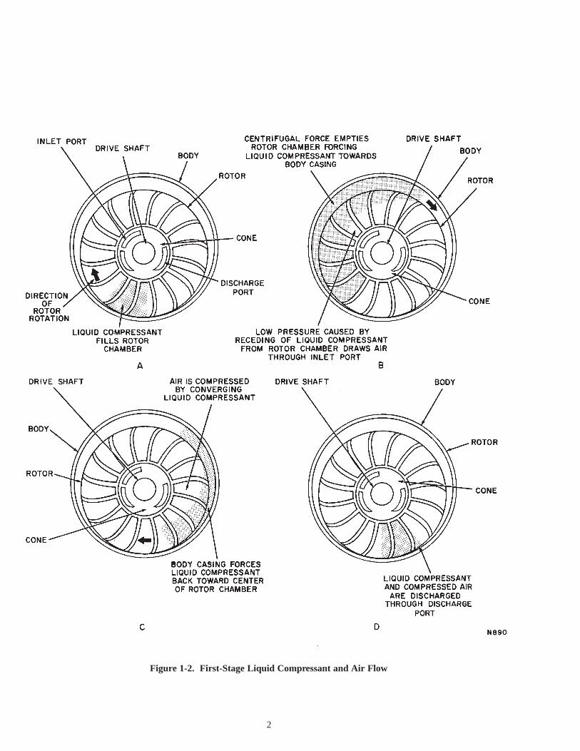
Figure 1-2. First-Stage Liquid Compressant and Air Flow
2

3
Figure 2-1. Typical Piping Connections
SECTION 2OPERATION
2-1 PREPARATION FOR INITIAL START-UP
NoteContact your Nash Representative for start-upassistance.
2-2 Liquid Compressant (Seal Water)
Piping connections must be made to a liquid compressantsupply. (See Figure 2-1.) The usual liquid compressant isfresh water at 60ºF (15ºC). Variations in the flow rate of±50 percent will not damage the pump, but wide variationsin flow may alter pump capacity.
CAUTIONTHE LIQUID COMPRESSANT FLOW MUSTBE STARTED BEFORE STARTING THE PUMPDRIVE MOTOR, EVEN IF THE PUMP IS ONLYBEING OPERATED TO CHECK THEDIRECTION OF ROTATION.
2-3 Draining and FlushingBefore starting the vacuum pump upon completion of
alignment (as specified in Bulletin No. 642, InstallationInstructions, Nash Vacuum Pumps and Compressors), removethe seal water drain plugs (22 and 22-1, Figure 5-15) fromthe heads and body of the vacuum pump. Turn on the shutoffvalve for the seal water supply. Allow the seal water to flow
until there is a clear flow from all drains. Although thevacuum pump is flushed with inhibiting oil prior to shipment,a light film of rust may form before installation is complete.This film will disappear after the vacuum pump shaft hasbeen manually rotated a few times. Close the shut-off valvefor the seal water supply. Replace the seal water drain plugsusing a pipe thread compound.
2-4 Preliminary InspectionPerform the following preliminary inspections before
starting the pump:
WARNINGPERFORM ALL OF THE FOLLOWING STEPSIN ORDER TO ENSURE PERSONNEL SAFETYAND EQUIPMENT PROTECTION.
a. Isolate all power sources to the driver unit in order tomake certain that no accidental starting occurs.
b. Inspect the pump to make certain that all drain plugshave been properly installed.
c. Manually prime the pump with liquid compressant untilthere is a flow from the overflow.
d. Inspect the separator, the receiver, and the heat exchanges(if used) to make certain that all shipping plug protectorshave been removed and that all open connections havebeen plugged or piped.
e. Inspect all piping to make certain that proper connections

4
have been made to the pump and its basic system inaccordance with the Nash installation drawing(s) thathave been supplied with the pump. Make certain thatall piping is the correct size, securely connected, andproperly supported.
f. Check vacuum pump and drive hold-down bolts andbase or soleplate foundation bolts for tightness.
g. Inspect all other major operational componentconnections, associated with the pump, to makecertain that they are in accordance with therecommendations of their respective equipmentmanufacturers.
h. Inspect all pump control components (control valves,gauges, etc.) to make certain that they have beenlocated in accordance with the Nash installationdrawing(s). Make certain that these components arecorrectly oriented in the piping scheme in order toachieve the proper direction of flow and functionaloperation.
I. Inspect the pump inlet to make certain that the inletscreen and clean-out connections have been properlymade and are free of tools, equipment and debris.
j. Make certain that the liquid discharge connection isfree of obstructions.
k. Remove the coupling or V-belt guard and rotate thepump shaft by hand in the specified direction ofrotation by an arrow cast on the pump body and isillustrated on the installation drawing. THE PUMPSHAFT MUST ROTATE FREELY. If the pump shaftis bound and cannot be freed by rotating it manually,contact your Nash Representative for assistance.
CAUTIONDO NOT ATTEMPT TO FREE A PUMPSHAFT FROM A BINDING OR BOUNDCONDITION BY APPLYING POWER TO THEDRIVE MOTOR. SEVERE DAMAGE MAYRESULT.
CAUTIONNEVER OPERATE THE PUMP WITHOUTADEQUATE PRIME AND LIQUID SEALFLOW. HIGH LIQUID SEAL SUPPLYPRESSURES DO NOT NECESSARILYINDICATE THAT THE FLOW IS ADE-QUATE. CHECK FOR FLOW FROMVACUUM PUMP DISCHARGE (OR WATERTRAP SILENCER).
l. With main supply valves open and the pumpprimed, as in step c, bump the drive motor forthe pump in order to check for the properdirection of shaft rotation.
WARNINGMAKE CERTAIN THAT THE COUPLING ORV-BELT DRIVE IS ENCLOSED WITH AGUARD BEFORE STARTING THE DRIVEMOTOR.
2-5 STARTUP AND OPERATING CHECKS
When the preliminary inspection and preoperational checkprocedures have been completed, start the pump and checkpump operation as follows:
WARNINGIF THE PUMP IS TO BE CHECKED IN A SYS-TEM, NOTIFY THE APPROPRIATE PLANTPERSONNEL BEFORE PLACING A PUMP ONLINE, PARTICULARLY WHEN PLACING THEPUMP ON LINE FOR THE FIRST TIME.STARTING UP A SYSTEM UNEXPECTEDLYMAY CAUSE PERSONNEL INJURY.
NoteRefer to Troubleshooting, Section 3, if anyoperating difficulties arise when performing thefollowing steps.
a. Check the pump and the system for adequate prime andthen turn on all main water supply sources to the pumpor heat exchanger.
b. With the water supply sources turned on and all personneland equipment clear of the pump system, apply power tothe drive motor.
NoteIf pump operation becomes unstable, pumpvibration levels will increase and the pumpingvolume will de- crease. IF THE PUMP DOESNOT STABILIZE, SHUT DOWN THE SYSTEMIMMEDIATELY, AND DETERMINE THECAUSE.
c. While the pump is being stabilized at the required inletvacuum, check the flow of liquid seal (water) to the pump.Make certain that the liquid seal is flowing out of thewater trap silencer drain.
d. Maintain a constant check on the temperature of the pumpcasing during the startup procedure. If the temperaturerises rapidly or is 40ºF (5ºC). or more above the liquidcompressant temperature, shut down the unit immediatelyand determine the cause.
e. After starting the pump, monitor the temperature of thebearing bracket until the bearing bracket temperaturesstabilize for a minimum of 30 minutes.
CAUTIONIF A BEARING BRACKET TEMPERATURE ISMORE THAN 50ºF (10ºC). ABOVE THE PUMPCASING TEMPERATURE, SHUT DOWN THEPUMP IMMEDIATELY AND DETERMINE THECAUSE.
CAUTIONI F ABNORMAL BEARING NOISE,VIBRATION, ODOR OR SMOKING OCCUR,SHUT DOWN THE PUMP IMMEDIATELY TODETERMINE THE CAUSE.

f. Check the pump for vibration and noise. Excessivevibration and noise is an abnormal condition on a Nashpump. Shut down the pump immediately and determinethe cause.
g. Check the speed (RPM) of pump shaft rotation by pryingthe nameplate cap from the fixed bearing outer cap andinserting a tachometer with a shaft extension, if necessary.Compare the measured speed with the rated speed forthe pump. The rated operating speed and capacity canbe determined from the purchase specifications or byconsulting with your Nash Representative.
5
h. After the pump has been running for ten minutes withsteady leakage from the stuffing box, tighten the glandnuts evenly one-quarter turn. Repeat at ten minuteintervals until there is a leakage of approximately 45 to60 drops per minute from the gland with no overheating.This dripping is necessary to provide lubrication for thepacking and thereby prevent it from scoring and burningthe shaft. Subsequent tightening of the gland nuts one-quarter turn should be done with the pump operating atnormal working temperature and vacuum.
SECTION 3TROUBLESHOOTING
3-1 LOCATING TROUBLES
Nash TC two-stage vacuum pumps require little attentionother than checking the ability of the vacuum pump to obtainfull volume or maintain constant vacuum. If a V-belt driveis used, V-belt tension should be checked periodically andthe V-belt should be inspected for excessive wear. V-beltsare normally rated for service lives of 24,000 hours. Ifoperating difficulties arise, make the following checks:a. Check for proper seal water flow rate as specified in
paragraph 2-2.b. Check for the correct direction of vacuum pump shaft
rotation as cast on the body of the vacuum pump.c. Check that the vacuum pump operates at the correct
rpm—not necessarily the test rpm stamped on the
vacuum pump nameplates. (Refer to Paragraph 2-5,step g.)
d. Check for a restriction in the gas inlet line.e. If the pump is shut down because of a change in tem-
perature, noise and/or vibration from normal operatingconditions, check bearing lubrication, bearings condition,and coupling or V-belt drive alignment. Refer to BulletinNo. 642, Installation Instructions, Nash Vacuum Pumpsand Compressors, for alignment procedures and V-belttensioning.
NoteIf the trouble is not located through these checks,call your Nash Representative before dismantlingor disassembling the vacuum pump. He will assistin locating and correcting the trouble.
4-1 PERIODIC MAINTENANCE
NoteThe following schedules should be modified asnecessary for your specific operating conditions.
4-2 Six-Month Intervalsa. If the drive coupling is lubricated, it should be filled with
oil or grease in accordance with the couplingmanufacturer’s instructions.
b. Check the pump bearings and lubricate, if necessary, asspecified in paragraph 4-4.
c. Relubricate the drive motor bearings according to themotor manufacturer’s instructions.
d. Check to ensure that the lobe unloader orifice in the orificeplug in body is not plugged as follows:
1. Remove pipe plug (22-1, Figure 5-15) from fixedbearing end head (103) and inspect orifice plug (21).
2. If orifice is plugged, use rod to clean out anyobstructions.
3. If orifice plug cannot be cleaned with rod, use Allenwrench and remove orifice plug. Remove
obstruction if possible and reinstall or replace orificeplug.
4. Reinstall pipe plug in fixed bearing end head.
4-3 Twelve-Month Intervalsa. Inspect the pump bearings and lubricate, if necessary, as
specified in Paragraph 4-4.b. Replace the stuffing box packing as specified in Paragraph
4-5.
4-4 Bearing LubricationThe pumps covered in this Bulletin have grease lubricated
bearings installed in bearing brackets with grease fittings.Bearings are lubricated before shipment and require nolubrication for approximately six months.
NoteLubricate the bearings every year, unless the pumpis being operated in a corrosive atmosphere or witha liquid compressant other than water, in which casethe interval should be shortened. Lubrication shouldbe done while pump is running.
SECTION 4PREVENTIVE MAINTENANCE
6
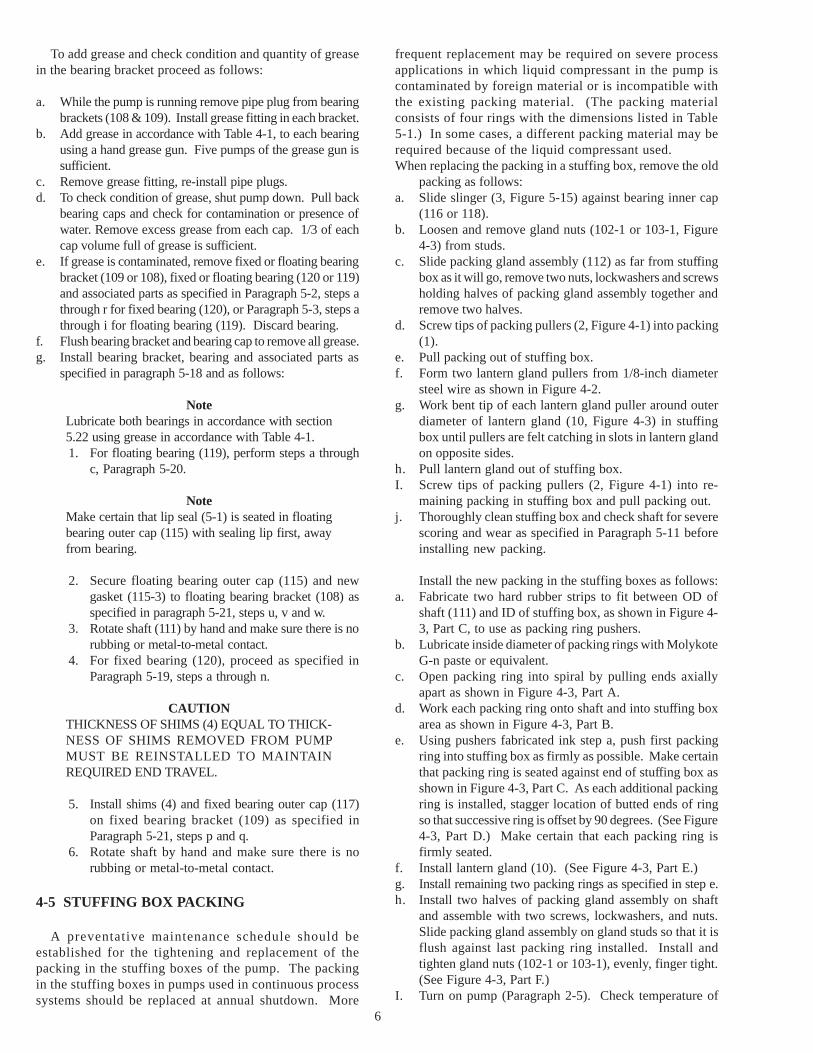
To add grease and check condition and quantity of greasein the bearing bracket proceed as follows:
a. While the pump is running remove pipe plug from bearingbrackets (108 & 109). Install grease fitting in each bracket.
b. Add grease in accordance with Table 4-1, to each bearingusing a hand grease gun. Five pumps of the grease gun issufficient.
c. Remove grease fitting, re-install pipe plugs.d. To check condition of grease, shut pump down. Pull back
bearing caps and check for contamination or presence ofwater. Remove excess grease from each cap. 1/3 of eachcap volume full of grease is sufficient.
e. If grease is contaminated, remove fixed or floating bearingbracket (109 or 108), fixed or floating bearing (120 or 119)and associated parts as specified in Paragraph 5-2, steps athrough r for fixed bearing (120), or Paragraph 5-3, steps athrough i for floating bearing (119). Discard bearing.
f. Flush bearing bracket and bearing cap to remove all grease.g. Install bearing bracket, bearing and associated parts as
specified in paragraph 5-18 and as follows:
NoteLubricate both bearings in accordance with section5.22 using grease in accordance with Table 4-1.1. For floating bearing (119), perform steps a through
c, Paragraph 5-20.
NoteMake certain that lip seal (5-1) is seated in floatingbearing outer cap (115) with sealing lip first, awayfrom bearing.
2. Secure floating bearing outer cap (115) and newgasket (115-3) to floating bearing bracket (108) asspecified in paragraph 5-21, steps u, v and w.
3. Rotate shaft (111) by hand and make sure there is norubbing or metal-to-metal contact.
4. For fixed bearing (120), proceed as specified inParagraph 5-19, steps a through n.
CAUTIONTHICKNESS OF SHIMS (4) EQUAL TO THICK-NESS OF SHIMS REMOVED FROM PUMPMUST BE REINSTALLED TO MAINTAINREQUIRED END TRAVEL.
5. Install shims (4) and fixed bearing outer cap (117)on fixed bearing bracket (109) as specified inParagraph 5-21, steps p and q.
6. Rotate shaft by hand and make sure there is norubbing or metal-to-metal contact.
4-5 STUFFING BOX PACKING
A preventative maintenance schedule should beestablished for the tightening and replacement of thepacking in the stuffing boxes of the pump. The packingin the stuffing boxes in pumps used in continuous processsystems should be replaced at annual shutdown. More
frequent replacement may be required on severe processapplications in which liquid compressant in the pump iscontaminated by foreign material or is incompatible withthe existing packing material. (The packing materialconsists of four rings with the dimensions listed in Table5-1.) In some cases, a different packing material may berequired because of the liquid compressant used.When replacing the packing in a stuffing box, remove the old
packing as follows:a. Slide slinger (3, Figure 5-15) against bearing inner cap
(116 or 118).b. Loosen and remove gland nuts (102-1 or 103-1, Figure
4-3) from studs.c. Slide packing gland assembly (112) as far from stuffing
box as it will go, remove two nuts, lockwashers and screwsholding halves of packing gland assembly together andremove two halves.
d. Screw tips of packing pullers (2, Figure 4-1) into packing(1).
e. Pull packing out of stuffing box.f. Form two lantern gland pullers from 1/8-inch diameter
steel wire as shown in Figure 4-2.g. Work bent tip of each lantern gland puller around outer
diameter of lantern gland (10, Figure 4-3) in stuffingbox until pullers are felt catching in slots in lantern glandon opposite sides.
h. Pull lantern gland out of stuffing box.I. Screw tips of packing pullers (2, Figure 4-1) into re-
maining packing in stuffing box and pull packing out.j. Thoroughly clean stuffing box and check shaft for severe
scoring and wear as specified in Paragraph 5-11 beforeinstalling new packing.
Install the new packing in the stuffing boxes as follows:a. Fabricate two hard rubber strips to fit between OD of
shaft (111) and ID of stuffing box, as shown in Figure 4-3, Part C, to use as packing ring pushers.
b. Lubricate inside diameter of packing rings with MolykoteG-n paste or equivalent.
c. Open packing ring into spiral by pulling ends axiallyapart as shown in Figure 4-3, Part A.
d. Work each packing ring onto shaft and into stuffing boxarea as shown in Figure 4-3, Part B.
e. Using pushers fabricated ink step a, push first packingring into stuffing box as firmly as possible. Make certainthat packing ring is seated against end of stuffing box asshown in Figure 4-3, Part C. As each additional packingring is installed, stagger location of butted ends of ringso that successive ring is offset by 90 degrees. (See Figure4-3, Part D.) Make certain that each packing ring isfirmly seated.
f. Install lantern gland (10). (See Figure 4-3, Part E.)g. Install remaining two packing rings as specified in step e.h. Install two halves of packing gland assembly on shaft
and assemble with two screws, lockwashers, and nuts.Slide packing gland assembly on gland studs so that it isflush against last packing ring installed. Install andtighten gland nuts (102-1 or 103-1), evenly, finger tight.(See Figure 4-3, Part F.)
I. Turn on pump (Paragraph 2-5). Check temperature of

pump stuffing box area as pump operates. Make certainthere is leakage from stuffing box at all times. If there isno leakage or if stuffing box overheats, shut down pumpand determine cause.
j. After pump has been running for ten minutes with steadyleakage from stuffing box, tighten gland nuts evenly one-quarter turn. Repeat at ten-minute intervals until thereis leakage of approximately 45 to 60 drops per minutefrom the gland with no overheating. This dripping isnecessary to provide added lubrication for packing andthereby prevent it from scoring and burning shaft.Subsequent tightening of gland nuts one-quarter turnshould be done with pump operating at normal workingtemperatures and vacuum.
4-6 SHUTDOWN PERIODS
If the pump is shut down for 2 to 3 weeks, rotate thevacuum pump and recirculating pump (if used) by hand atleast once every week to prevent rust buildup between castiron parts which may result in seizing. If the pump must betaken out of service for more than 3 weeks up to one year,proceed as follows to prevent seizing during the storage dueto rust formation:
These preservation procedures apply to all-cast-iron pumpsonly, maintained in covered storage.
a. Remove pipe plugs (22 and 22-1, Figure 5-15) from pumpbody (101), and heads (102 and 103) and drain all liquidfrom pump. Replace pipe plugs.
b. Remove all packing as specified in paragraph 4-5 andflush out stuffing boxes with rust inhibitor. Reinstallpacking.
c. Touch up any areas where paint has chipped and applyHoughton’s Rust Veto #344 coating compound, orequivalent, to external surfaces as necessary.
d. Disconnect discharge piping and blank off pumpdischarge flange.
7
Table 4-1. General Grease Specifications
General Requirements
A. industrial bearing grease.
B. NLG1 #2
C.@ 100 (38 C) - 500 SSU (108 cSt)@ 210 (99 C) - 58 SSU (10 cSt)
D. Lithium, Lithium Complex or Polyurea foroptimum WATER RESISTANCE.
E. at operating temperature:1. Operating temperature range; at least 0 to 250 F (18
to 121 C)2. "Long-Life" performance3. Good mechanical and chemical stability.
Premium quality
Consistency grade:
Oil viscosity (minimum):
Thickener (Base):
Performance characteristics
o o
o o
o o o
o
F.1. Oxidation inhibitors2. Rust inhibitors
G.1. Anti-wear agents2. Corrosion inhibitors3. Metal deactivators
H.1. Extreme pressure (EP)* agents2. Molybdenum disulfide (MoS )3. Tackiness agents
* Some greases exhibit EP characteristics without theuse of EP additives. These EP characteristics are notobjectionable.
Additives - Mandatory:
Additives - Optional:
Additives - Objectionable:
2
NASH STANDARD GREASE RECOMENDATIONS(By Manufacturer)
The following is a list of some greases that exhibit the desiredcharacteristics required by Nash:
Amoco Rykon Premium 2Atlantic Arco MultipurposeChevron Chevron SRI-2Exxon Unirex N2Gulf Oil Gulfcrown No.2Mobil Mobilux 2Shell Oil Alvania 2 or Dolium RTexaco Premium RB #2
NOTE: This list is not an endorsement of these products and isto be used only for reference. A customer can have his locallubricant supplier cross reference these greases for anequivalent or current grease so long as it meets the GeneralRequirements.
Grease Compatibility Note: The above listed greases arecompatible with Nash Standard grease, Chevron SRI-2. Tomaximize a grease lubricant's performance, however, it isrecommended that intermixing of different greases be kept at aminimum.
Grease Manufacturer Product
Figure 4-2. Stuffing Box Lantern Gland Puller
Figure 4-1. Removing Stuffing Box Packing
1. Packing Ring2. Packing Pullers
10. Lantern Gland

8
e. Fill pump with water-soluble preserving oil, J.L. QuimbyNRP100 or equivalent, through inlet flange.
f. Rotate pump shaft by hand 10 to 15 revolutions.
NoteFor long term preservation procedures for storageperiods of more than 1 year, contact your NashRepresentative.
g. When pump is to be put back in service, proceed asfollows:
1. Remove pipe plugs (22-1 and 22-2) from pump bodyand heads and drain all preserving oil.
2. Remove blanks from pump discharge flanges andreconnect discharge piping.
3. Repack stuffing boxes with new packing as specifiedin paragraph 4-5.
4. Flush pump as specified in paragraph 2-3.5. Replace drain and vent pipe plugs in body using
Key-Tite pipe compound. Start pump as specifiedin Paragraphs 2-4 and 2-5.
Figure 4-3. Packing Stuffing Boxes
1. Packing Ring102-1. Gland Nut
2. Lantern Gland SupplyConnection
111. Shaft102. Floating Bearing End Head112. Packing Gland Assembly
103. Fixed Bearing End Head3. Packing Ring Pusher
103-1. Gland Nut10. Lantern Gland
Note: Rotated 90 degrees to show gland studs and nuts.

9
SECTION 5DISASSEMBLY, INSPECTION AND REASSEMBLY
5-1 DISMANTLING PUMP
Before disassembling the pump, isolate the electrical inputand disconnect the seal liquid connections, coupling to drivemotor or V-belt drive, and inlet and outlet connections.Disassemble and reassemble the pump on a level surface. Markall parts as they become accessible during disassembly to ensurecorrect positioning for reassembly. Before starting disassembly,collect the parts, materials and standard tools, and fabricate thespecial tools listed in the following paragraphs, which arerequired for disassembly and reassembly of the pump.
Parts and Materialsa. Minimum recommended spares specified in Legend for
Figure 5-15 (which should be kept onhand at alltimes).
NoteIt is not advisable to disassemble a pump unless thefollowing replacement items are available for reassembly:two sets of stuffing box packing (1); one set of adjustingshims (4); one set of gaskets; and floating and fixed bearings(119 & 120). (Refer to Table 5-1.)
b. Molykote G-n Paste or equivalent.c. Locquic Primer T and Loctite 242 (required only if gland
studs (102-2 or 103-2) require replacement).d. Yellow grease.e. Grease as specified in Table 4-1.f. Solvent such as kerosene.g. Two 3/4-11 eye bolts (M20X2.5mm for metric pumps)
with nuts to remove and install heads (102 and 103).h. Two 2 inch bushings with clearance holes for attaching 3/
4-11 eye bolts and nutsI. Two ½-13 jackscrews (M12X1.25mm for metric pumps)
as shown in Figure 5-13 to set end travel.
Standard Toolsa. Socket wrench set with shaft extension. In most cases,
open-end or box wrenches can be substituted for socketwrenches.
b. Hexagonal (Allen) wrenches.c. Spanner wrench (for fixed bearing locknut).
NoteMachinist’s hammer and brass drift can be substitutedif spanner wrench is not available.
d. Bearing puller.e. Press: approximately 80-ton capacity. Press must indicate
amount of force applied and is only required if rotor orshaft requires replacement.
f. Spirit level.g. Leaf (feeler) gauge.h. Metal straightedge.I. Rawhide mallet.j. Machinist’s dial indicator with suitable clamps and mounts.k. Needle-nosed pliers.l. Propane torch and 250ºF (121ºC) temp stick (required only
if gland studs require replacement).m. Thermally insulated gloves.n. Hoist and slings.o. Hydraulic jack, 20 ton capacity.p. Induction heater. Used to heat bearings (119 and 120) for
installation.
WARNINGMAKE PROVISIONS FOR HANDLING HEAVYPARTS DURING DISASSEMBLY TO AVOIDINJURY TO PERSONNEL OR DAMAGE TOPARTS. REFER TO TABLE 5-2 FORAPPROXIMATE WEIGHTS OF PARTS.
Fabricated Toolsa. Bushing or pipe section as specified in Paragraph 5-6,
step d (required only if rotor or shaft requires replace-ment).
b. Jack back-up plate (Figure 5.2).c. Split Ring (Figure 5.2).d. Eight spacers (Figure 5.2).e. Shaft sleeve tool (Figure 5.7).
NoteDo not disassemble the pump beyond the pointrequired to remedy the trouble that has beenobserved. Before disassembling the pump, removethe drain plugs (22, 22-1, Figure 5-15) from thefloating and fixed bearing end heads (102 and 103)to drain all liquid from the pump. Fasten mountingfeet of drive end head to level surface.
Part Name(See Figure 5-15.) TC-11 Iron
Packing (1)* - Dimensions 3/4 square x 5.25 ID x 6.75 OD
No. of rings per Stuffing Box 4
Lip Seal (5), Floating and FixedBearing Inner Caps
Johns Manville Type LUP (2 req.)5.25 shaft dia.6.25 bore dia.1/2 wide
Lip Seal (5-1), Floating BearingOuter Cap
Johns Manville Type LUP (1 req.)3.74 shaft dia.4.528 bore dia..472 wide
Body Gasket (101-3 and 101-4)**Qty. Floating Bearing End 6 .010 thick
Qty. Fixed Bearing End 6 .010 thick
Cone Gaskets(104-2 and 105-3).010 thick, Qty.
1 .010 thick
Floating Bearing (119)
Taper roller bearing Timken Set2 Cones No. 714501Cup No. 7151D1 Spacer No. X3S-71450Bench Play 0.012 inch
Fixed Bearing (120)
* Contact your Nash Representative for required packing materialspecification.
** Quantities listed are for trial assembly with extra gaskets at thefixed bearing end to allow removal of gaskets to obtain the finalcorrect rotor (end) travel.
Table 5-1 Pump DataNote: All dimensions are in inches

I. Fabricate jack backup plate, three spacers and split ringas shown in Figure 5-2.
j. Thread one inner nut (5, Figure 5-3) each onto four ½-13 by 36-inch long tensile steel rods approximately 3 ½inches from end of rod and install flat washers (3) againstnuts.
k. Slide fixed bearing inner cap back to gland studs farenough to insert split ring between fixed bearing andinner cap. Make sure the split ring is on shaft chamferand oriented the same way as the shaft chamfer.
l. Align four holes in split ring with tapped holes in fixedbearing inner cap; insert four spacers between split ringand inner cap; insert threaded rods (end with nutsinstalled) through split ring and spacers, and threadthrough holes in inner cap until flat washers bear againstsplit ring. Secure threaded rods with flat washers andouter nuts tightened against inner cup flange. Tighteninner nuts.
m. Install jack backup plate, fabricated in step j, on threadedrods and secure with flat washers, lockwashers and nutson ends of rods. Support backup plate until hydraulicjack applies sufficient pressure in step n to hold plate inplace.
10
103. Fixed Bearing EndHead
109. Fixed Bearing Bracket
109-1. Bearing BracketScrew (Jackscrew)
Figure 5-1. Removing Fixed Bearing Bracket
5-2 Disassembling Fixed Bearing Enda. Remove three fixed bearing outer cap screws (117-1,
Figure 5-15), four nuts (117-4), four screws (117-2) andfixed bearing outer cap (117) from fixed bearing bracket(109).
b. Remove shims. Discard any damaged metal shims andall paper shims, if present. Measure and record totalthickness of shims and gaskets.
c. Remove and discard fixed bearing ring gasket (120-3).d. Remove four fixed bearing bracket screws.
e. Install two straps and chain hoist around two top ribs offixed bearing bracket as shown in Figure 5-1. Supportbut do not lift bearing bracket.
f. Install two bearing bracket screws in tapped holes inflange of fixed bearing bracket to serve as jackscrews(See Figure 5-1).
g. Tighten two jackscrews installed in step f evenly untilbearing bracket flange is free of head. Using chain hoist,carefully slide bearing bracket off fixed bearing and shaft.Remove two jackscrews.
h. Bend tab of fixed bearing lockwasher (120-2, Figure 5-15) out of notch in fixed bearing locknut (120-1). Usingspanner wrench or punch and hammer, loosen andremove locknut and lockwasher.
Figure 5-15Index No.
Part NameWeight-Pounds
TC-11 Iron101 Body 1320
102Floating Bearing EndHead
528
103Fixed Bearing EndHead
532
104Floating Bearing EndCone
121
105Fixed Bearing EndCone
95
108109
Floating and FixedBearing Bracket
138 each
110 Rotor 1166
111
-
Shaft
Total Pump
520
4700
119
120
Floating Bearing
Fixed Bearing35 each
Table 5-2 Approximate Weights of Parts
CAUTIONMAKE CERTAIN THAT HYDRAULIC JACK,BACKUP PLATE, SPLIT RINGS AND CAPARE SQUARE AND THAT FORCE IS APPLIEDEVENLY TO AVOID DAMAGE.
n. Place hydraulic jack between jack backup plate and endof shaft. Apply pressure to remove bearing. Discardbearing.
11
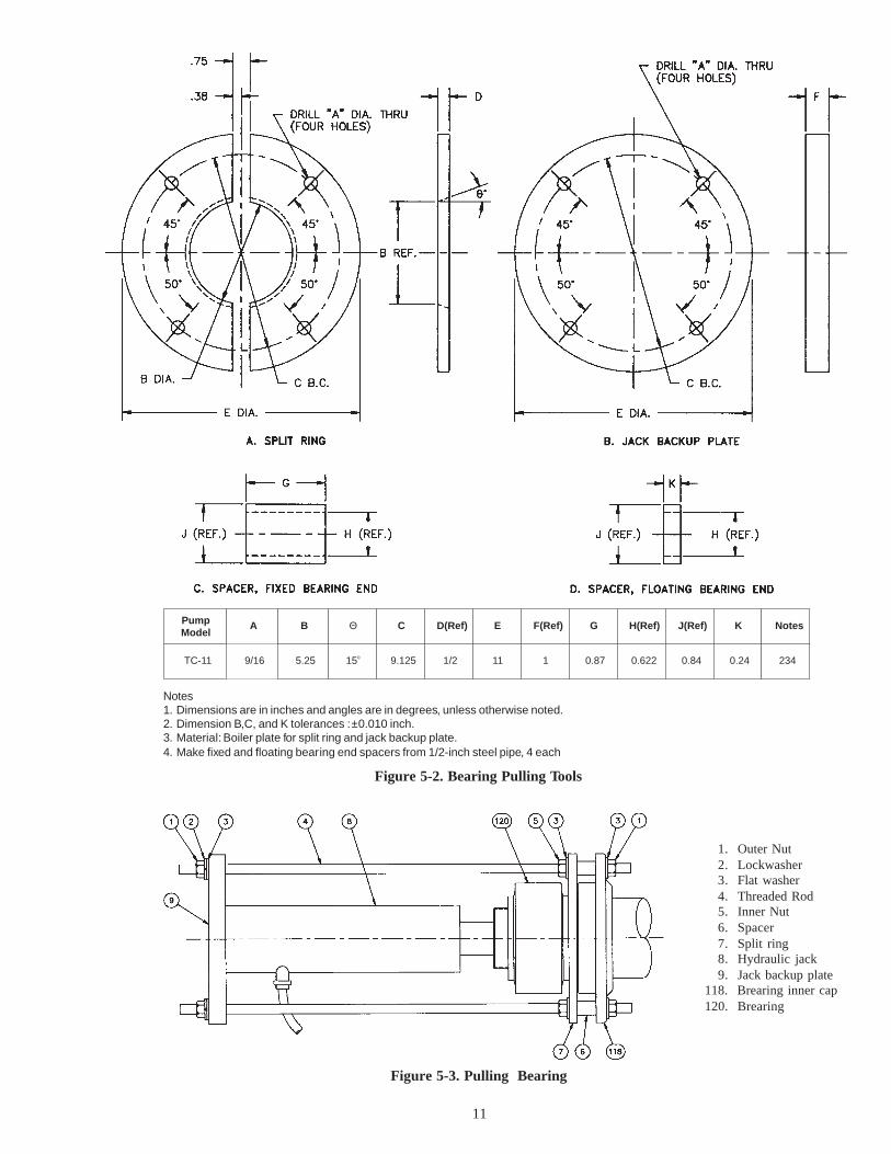
PumpModel
A B Θ C D(Ref) E F(Ref) G H(Ref) J(Ref) K Notes
TC-11 9/16 5.25 15o 9.125 1/2 11 1 0.87 0.622 0.84 0.24 234
Notes1. Dimensions are in inches and angles are in degrees, unless otherwise noted.2. Dimension B,C, and K tolerances : ±0.010 inch.3. Material: Boiler plate for split ring and jack backup plate.4. Make fixed and floating bearing end spacers from 1/2-inch steel pipe, 4 each
Figure 5-2. Bearing Pulling Tools
1. Outer Nut2. Lockwasher3. Flat washer4. Threaded Rod5. Inner Nut6. Spacer7. Split ring8. Hydraulic jack9. Jack backup plate
118. Brearing inner cap120. Brearing
Figure 5-3. Pulling Bearing
12
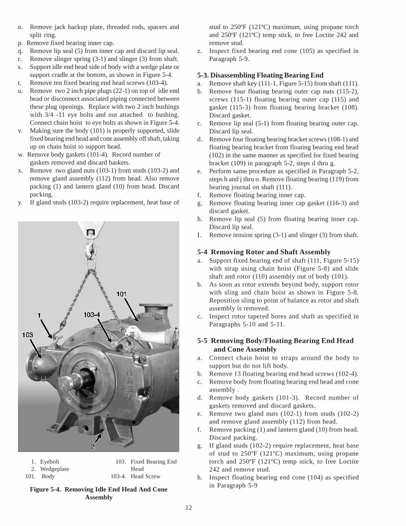
Figure 5-4. Removing Idle End Head And ConeAssembly
1. Eyebolt2. Wedgeplate
101. Body
103. Fixed Bearing EndHead
103-4. Head Screw
o. Remove jack backup plate, threaded rods, spacers andsplit ring.
p. Remove fixed bearing inner cap.q. Remove lip seal (5) from inner cap and discard lip seal.r. Remove slinger spring (3-1) and slinger (3) from shaft.s. Support idle end head side of body with a wedge plate or
support cradle at the bottom, as shown in Figure 5-4.t. Remove ten fixed bearing end head screws (103-4).u. Remove two 2 inch pipe plugs (22-1) on top of idle end
head or disconnect associated piping connected betweenthese plug openings. Replace with two 2 inch bushingswith 3/4 -11 eye bolts and nut attached to bushing.Connect chain hoist to eye bolts as shown in Figure 5-4.
v. Making sure the body (101) is properly supported, slidefixed bearing end head and cone assembly off shaft, takingup on chain hoist to support head.
w. Remove body gaskets (101-4). Record number ofgaskets removed and discard baskets.
x. Remove two gland nuts (103-1) from studs (103-2) andremove gland assembly (112) from head. Also removepacking (1) and lantern gland (10) from head. Discardpacking.
y. If gland studs (103-2) require replacement, heat base of
stud to 250ºF (121ºC) maximum, using propane torchand 250ºF (121ºC) temp stick, to free Loctite 242 andremove stud.
z. Inspect fixed bearing end cone (105) as specified inParagraph 5-9.
5-3. Disassembling Floating Bearing Enda. Remove shaft key (111-1, Figure 5-15) from shaft (111).b. Remove four floating bearing outer cap nuts (115-2),
screws (115-1) floating bearing outer cap (115) andgasket (115-3) from floating bearing bracket (108).Discard gasket.
c. Remove lip seal (5-1) from floating bearing outer cap.Discard lip seal.
d. Remove four floating bearing bracket screws (108-1) andfloating bearing bracket from floating bearing end head(102) in the same manner as specified for fixed bearingbracket (109) in paragraph 5-2, steps d thru g.
e. Perform same procedure as specified in Paragraph 5-2,steps h and j thru o. Remove floating bearing (119) frombearing journal on shaft (111).
f. Remove floating bearing inner cap.g. Remove floating bearing inner cap gasket (116-3) and
discard gasket.h. Remove lip seal (5) from floating bearing inner cap.
Discard lip seal.I. Remove tension spring (3-1) and slinger (3) from shaft.
5-4 Removing Rotor and Shaft Assemblya. Support fixed bearing end of shaft (111, Figure 5-15)
with strap using chain hoist (Figure 5-8) and slideshaft and rotor (110) assembly out of body (101).
b. As soon as rotor extends beyond body, support rotorwith sling and chain hoist as shown in Figure 5-8.Reposition sling to point of balance as rotor and shaftassembly is removed.
c. Inspect rotor tapered bores and shaft as specified inParagraphs 5-10 and 5-11.
5-5 Removing Body/Floating Bearing End Headand Cone Assembly
a. Connect chain hoist to straps around the body tosupport but do not lift body.
b. Remove 13 floating bearing end head screws (102-4).c. Remove body from floating bearing end head and cone
assembly .d. Remove body gaskets (101-3). Record number of
gaskets removed and discard gaskets.e. Remove two gland nuts (102-1) from studs (102-2)
and remove gland assembly (112) from head.f. Remove packing (1) and lantern gland (10) from head.
Discard packing.g. If gland studs (102-2) require replacement, heat base
of stud to 250ºF (121ºC) maximum, using propanetorch and 250ºF (121ºC) temp stick, to free Loctite242 and remove stud.
h. Inspect floating bearing end cone (104) as specifiedin Paragraph 5-9

13
5-6 Removing Rotor From ShaftIf inspection of the rotor (Paragraph 5-10) or the shaft
(Paragraph 5-11) indicates that either part requiresreplacement or repair which requires disassembly, proceedas follows:a. Measure and record dimension A, Figure 5-7, from
outer face of rotor taper bore to floating bearingjournal shoulder.
b. Thread floating and fixed bearing locknuts (119-1 and120-1, Figure 5-15) on shaft to protect threads.
c. Lift rotor and shaft assembly with chain hoist and sling.d. Slide bushing or pipe section sized to fit over fixed bearing
end of shaft with face of bushing contacting rotor hubface only.
NotePress with 80-ton capacity is required.
e. Position rotor and shaft assembly in press large enoughto handle rotor diameter with floating bearing end of shaftagainst press ram and bushing, installed in step d, againstpress backup plate.
f. Make provision to support fixed bearing end of shaft asit is pushed from rotor. Support rotor with blocks orsling passed through rotor blades and around each shroud.
g. Make certain that shaft is level and apply ram force toremove shaft from rotor.
h. If rotor taper bore is to be machined oversize, contactyour local Nash representative for guidance ondimensions to be used.
5-7 Removing Cone from HeadIf inspection of the cone (Paragraph 5-9) indicates that
the cone must be replaced or reworked, proceed as follows:a. Insert Allen wrench in socket of each cone screw (104-1
or 105-1, Figure 5-15) in turn; tap Allen wrench withmallet as shown in Figure 5-5 to loosen and remove eightcone screws.
Figure 5-6. Checking Cone for Wear
Figure 5-5. Loosening Cone Screws
b. Tap side of floating or fixed bearing end cone (104 or105) with soft-headed mallet to free cone from head (102or 103).
c. Pull cone from head.d. Remove gaskets (104-3 or 105-3). Record number of
gaskets removed and discard gaskets.
5-8 INSPECTION OF DISASSEMBLED PARTS
With the pump disassembled, inspect the parts for wearas described in the following paragraphs.
NoteIf there is any question about the reusability orrepair of worn major pump parts, contact yourlocal Nash Representative.
5-9 ConesNormally worn tapered surfaces of the cones will be
smooth, requiring only cleaning and light filing around theports and tips. If foreign material has entered the pumpsuction inlet during operation, circular score marks may benoticed around the outside of the cone tapers. Inspect thecones for damage and wear as follows:
Check for uneven wear and scoring between the ports andat the edges of the ports with a straightedge and feeler gaugeas shown in figure 5-5.
Localized wear or scoring not more than 0.030-inch deepis acceptable unless the pump is required to operate at ornear maximum capacity. Replace the cone if the localizedwear or scoring exceeds 0.030 inch in depth. Minor pittingis acceptable.
NoteA cone with uneven wear or scoring may berepaired by building up the surface by flamespraying and remachining. Contact your NashRepresentative for specific requirements anddimensions before attempting any repairs.
The cones have an 8-degree taper. If the cone taperedsurface is worn or requires light machining, additionalgaskets (104-3 or 105-3, Figure 5-15) must be added betweenthe cone (104 or 105) and the head (102 or 103) duringreassembly to compensate for the total amount of materialremoved on a 7 to 1 ratio. For example, if 0.003 inch isremoved from the cone tapered surface, 0.021-inch additionalthickness of gaskets is required. Gaskets supplied are 0.010-in thick each; therefore, two to three gaskets per cone mustbe added. The maximum total thickness of gaskets that canbe placed under each cone is 0.050 inch.

14
5-10 RotorInspect the taper cone bores of the rotor on the same basis
as the tapered surface of the cones as follows:Check for uneven wear, undercutting or scalloping on the
cone bore tapered surface with a straightedge and feeler gaugein a manner similar to that shown in Figure 5-6. Localizedwear, undercutting or scalloping not more than 0.030-inchdeep is acceptable. Replace the rotor if localized wear,undercutting or scalloping exceeds 0.030 inch in depth.Minor pitting is acceptable.
If the rotor tapered bore is worn or requires lightmachining, the total amount of material that is removed mustbe compensated for on a 7 to 1 ratio by placing gaskets (104-3 and 105-3, Figure 5-15) under the cones in the same manneras specified in Paragraph 5-9. The maximum total thicknessof gaskets that can be placed under each cone is as specifiedin Paragraph 5-9.
5-11 ShaftCheck the shaft diameters on which the packing seats for
excessive wear. If the shaft is scored or worn through themetalized surface, remove the metalizing, clean the shaftthoroughly, and remetalize. Contact your NashRepresentative for procedures and dimensions required.
5-12 REASSEMBLING PUMP
CAUTIONTHOROUGHLY CLEAN ALL PARTS BEFOREREAS- SEMBLY. BE SURE TO REMOVE ALLOLD GASKET MATERIAL FROMMOUNTING FLANGES. REMOVE BURRSFROM MATING SURFACES AND MOUNTINGFACES.
5-13 Reassembling Rotor and ShaftTo reassemble the rotor on the shaft, proceed as follows:
CAUTIONTHIS PROCEDURE APPLIES TO ASSEMBLYOF IRON ROTOR ON STEEL SHAFT ONLY.
Figure 5-7. Pressing Rotor onto shaft
a. File taper bores of rotor (110, Figure 5-15) to removeburrs and high spots.
b. Check shaft for dents or rough spots on rotor seat andbearing journals.
c. Stone or polish shaft smooth.
Allowable Force Tons
PumpSize
Shaft/Rotor at SameTemperature
Shaft/RotorTemperature
Differential of 20 Fo
MinimumMinimum MinimumMaximum
TC-11 56 20 Approximately 5 tons
d. Coat rotor hub bore and rotor seat of shaft with MolykoteG-n paste, or equivalent, to prevent damage from frictionor pick-up when shaft is pressed into rotor.
e. Thread fixed bearing locknut (120-1) and floating bearinglocknut (119-1) on shaft to protect threads. Place an icepack around shaft diameter to be pressed into rotor.
f. Check for proper rotation of rotor prior to assembly. Whenthe shaft temperature where the ice pack is placed isapproximately 20° F below room temperature, removeicepack. Slide floating bearing end of shaft (111) into rotormaking certain that rotor blades curve in clockwisedirection viewed from floating bearing end. Gently tapfixed end of shaft with soft-headed mallet.
g. Slide same bushing or pipe section used in disassembly,on floating bearing end of shaft. (See Figure 5-7.)
h. Sling rotor and shaft by a sling placed around outsidediameter at point of balance and place rotor and shaft inpress with fixed bearing end of shaft in line with ramend of press and face of bushing or pipe section contactingrotor hub face only, with bushing or pipe section supportedby press backup plate. Level rotor shaft assembly.
I. Press shaft into rotor until dimension A, Figure 5-7, fromouter face of rotor taper bore to floating bearing journalshoulder is within limits specified. Record force applied.Maximum allowable force and minimum allowable forceare noted on chart below.
CAUTION
1.Press Backup Plate2. Bushing or Pipe Section3.Press Ram
Pump Size Dimension A Inches
TC-11 11 25/32 to 11 27/32

15
IF ASSEMBLY FORCE RECORDED IS NOTWITHIN LIMITS SPECIFIED ABOVE, DONOT INSTALL ASSEMBLED ROTOR ANDSHAFT IN VACUUM PUMP. CONTACTYOUR LOCAL NASH REPRESENTATIVETO DETERMINE WHETHER ROTOR AND/OR SHAFT MUST BE REPLACED.
WARNINGBEFORE REMOVING ROTOR AND SHAFTASSEMBLY FROM PRESS, MOVE SLING TONEW POINT OF BALANCE TO AVOIDINJURY OR DAMAGE.
j. Remove bearing locknuts (119-1 and 120-1) from idleand drive ends of shaft.
5-14 Installing Cone in HeadIf one or both the head and cone assemblies have been
disassembled, reassemble them as follows:a. If new cone is being installed, check it carefully
against old cone for correct part number and removerust preventative from surfaces with solvent such askerosene.
b. File taper surfaces on the cone smooth, paying special
attention to edges of cone ports.c. Apply light coat of grease to replacement cone gaskets
(104-3 or 105-3, Figure 5-15) equal to numberremoved at disassembly, and position gaskets on head(102 or 103). If rotor or cone has been remachined asdescribed in Paragraphs 5-9 and 5-10, instal ladditional gaskets in accordance with requirementsspecified in Paragraphs 5-9 and 5-10.
d. Install two 3/4 eye bolts in holes 180º apart for driveend head or use 2 inch bushings with eye bolts foridle end head as described in paragraph 5.2. Removebolts fastening mounting feet of drive end head to levelsurface. Lay down heads so that the surface with coneside is up.
e. Lower cone into place on associated head makingcertain that eight holes in cone flange align withtapped holes in head. Thread in eight socket headcone screws (104-1 or 105-1) and tighten screws.
f. After tightening screws, tap Allen wrench with malletto finish tightening each screw.
Figure 5-8. Installing Rotor and Shaft Assembly
110. Rotor111. Shaft
2. Wedgeplate101. Body

5-15 Installing Body onto Floating Bearing EndHead and Cone Assembly
a. Fasten mounting feet of drive end head (102) to levelsurface.
b. If gland studs (102-2, Figure 5-15) have been removed,install new studs as follows:
1. Apply Locquic Primer T to tapped holes in headand stud threads. Allow primer to dry.
2. Apply Loctite 242 to stud threads and install studsin head.
c. Apply light coat of grease to each of six new floatingbearing end body gaskets (101-3) and position gasketson floating bearing end head (102).
d. Using straps and chain hoist, position body onto headand cone assembly. Make certain that head rabbet seatsin body bore and that 13 mounting holes in head alignwith tapped holes in body. Support idle end side of bodywith a wedge plate or supporting cradle.
e. Secure head to body with 13 screws (102-4).
16
5-16 Installing Rotor and Shaft Assemblya. Lift rotor and shaft assembly with sling and chain hoist
as shown in Figure 5-8 and install floating bearing endof shaft into body (101).
b. Keep moving rotor and shaft assembly, adjusting positionof sling as necessary, until shaft passes through floatingbearing end cone (104) and head (102), and rotor taperbore seats on cone.
5-17 Installing Fixed Bearing End Head and ConeAssembly on Body
a. If gland studs (103-2, Figure 5-15) have been removed,install new studs as follows:
1. Apply Locquic Primer T to tapped holes in headand stud threads. Allow primer to dry.
2. Apply Loctite 242 to stud threads and install studsin head.
b. Apply light coat of grease to each of six new fixed bearingend body gaskets (101-4) and position gaskets on fixedbearing end head (103).
c. Using eye bolts and chain hoist as specified in Paragraph5-2, step u, slide head and cone assembly over shaft (111)onto body. Make certain that head rabbet seats in bodybore and that 10 mounting holes in head align with tappedholes in body.
d. Secure head to body with five screws (103-4).
NoteDo not install five screws (103-4) at this time sinceit may be necessary to remove head to removegaskets (101-4) to obtain proper end travel. (Referto Paragraph 5-21.)
5-18 Assembling Floating and Fixed Bearing Endsa. Install new lip seals (5, Figure 5-15) in floating and fixed
bearing inner caps (116 and 118) as follows:
1. Apply light coat of grease to OD and sealing lips oflip seals.
2. Install lip seals in caps with sealing lips facing awayfrom bearing housing. Make certain that lip sealsare properly seated.
b. Install slingers (3) on floating and fixed bearing ends ofshaft (111).
c. Install floating and fixed bearing inner caps and floatingbearing inner cap gasket (116-3) on shaft.
d. Slide slingers and inner caps beyond bearing journalshoulder toward heads.
5-19 Installing Fixed Bearinga. Move shaft toward fixed bearing end of pump so that
rotor taper bore rides up on fixed bearing end to ensurethat shaft is centered in bearing housing. This can beaccomplished by using a soft-faced hammer or ram toimpact floating bearing end of shaft.
b. Push fixed bearing inner cap back toward head.
NoteMake certain that bearing locknuts (119-1 and120-1) have been removed from shaft.
CAUTIONMAKE CERTAIN THAT BEARING CUP ANDSPACER SUPPLIED WITH TAPERED ROLLERBEARINGS ARE NOT MISPLACED WHENTAPERED CONES ARE BEING HEATED. (SEEFIGURE 5-9). CUP, SPACER AND TAPEREDCONES ARE SUPPLIED AS A MATCHED SET;CUP AND/OR SPACER FROM ONE SETSHALL NOT BE USED WITH TAPEREDCONES FROM ANOTHER SET. SERIOUSCLEARANCE ERRORS CAN RESULT IF THISCAUTION IS NOT OBSERVED.
c. Heat two tapered cones of fixed bearing set, using hot airover and 250ºF (121ºC) temp stick, to 240º to 250ºF (116ºto 121ºC).
CAUTIONDO NOT HEAT BEARING CUP OR SPACER.
WARNINGUSE THERMALLY INSULATED GLOVESWHEN HANDLING HEATED TAPERED CONEBEARING TO AVOID SERIOUS BURNS.
Figure 5-9. Tapered Roller Bearing AssemblyExploded View
1. Tapered Cone Bearing 2. Bearing Cup3. Bearing Spacer

17
Figure 5-10. Installing Fixed Bearing
1. Bearing Journal2. Inner Tapered
Cone Bearing3. Bearing Cup
4. Bearing Spacer5. Outer Tapered Cone
Bearing
6. Fixed BearingLockwasher
7. Fixed Bearing Locknut8. Spanner Wrench
A B
C D
FE

18
d. Remove one tapered cone from heater or oven. Positionlarge end of taper toward shaft and line up ID of bearingwith shaft OD.
NoteThe following step must be performed as rapidlyas possible. As soon as heated tapered conecontacts shaft, it will cool rapidly and contract.Contraction may be sufficient to cause bearing toseize at the wrong location on the shaft, requiringthat the bearing be pulled, reheated and reinstalled.
e. Using one smooth, swift motion, center bearing onshaft and push bearing onto bearing journal until itcontacts bearing journal shoulder. (See Figure 5-10,Parts A and B.) MAKE CERTAIN THAT TAPEREDCONE IS SEATED AGAINST BEARING JOURNALSHOUL- DER. A bearing pusher may have to be usedto tap bearing if the bearing is not contacting thebearing journal shoulder.
f. Install chains around two top ribs of bearing bracket (109)as shown in Figure 5-1. Lift bearing bracket into position.
g. Install fixed bearing bracket (109) on head and secureeach with four screws (109-1).
NoteMake sure that pipe plugs (22) are installed inbrackets.
h. Install bearing cup over tapered cone bearing installedin step e being careful not to jam bearing cup in bearingbracket and making certain that cup is seated properlyon tapered cone bearing. (See Figure 5-10, Part B.)
I. Slide bearing spacer over shaft and into bearing bracketuntil it contacts tapered cone bearing. (See Figure 5-10,Part C.)
1. Leaf (Feeler) Gauge
Figure 5-11. Measuring BearingRoller-Cup Clearance
Figure 5-12. Measuring End Travel atFloating Bearing End
1. Threaded Rod2. Dial Indicator
j. Using thermally insulated gloves, remove second taperedcone bearing from heater or oven. Position small end oftaper towards shaft and line up ID of bearing with OD ofshaft.
k. Observing precaution in Note preceding step e and usingsmooth, swift motion, center bearing on shaft and pushbearing onto bearing journal until spacer installed in stepI is wedged between two tapered cone bearing. (See Figure5-10, Part D.)
l. Quickly install fixed bearing locknut (120-1) on shaft,carefully engage threads and tighten with spanner wrenchor punch and hammer. (See Figure 5-10, part F).
m. When bearing has cooled, proceed as follows:1. Remove locknut from shaft, drive bearing home
using bearing pusher.2. Install fixed lockwasher 120-2 (Figure 5-15), as
shown in Figure 5-10, Part F, with inner tab in slotin shaft.
3. Reinstall bearing locknut, tighten with spannerwrench and mallet, or punch and hammer, untilslot in locknut aligns with tab on lockwasher.
4. Bend lockwasher tab into locknut slot.n. Install new outer bearing ring gasket (120-3, Figure 5-
15) over shaft and against bearing.o. Install fixed bearing outer cap (117) on bearing bracket
(109).p. Align holes of inner and outer caps with holes in bearing
bracket and secure with four screws (117-2) and nuts(117-4).
5-20 Installing Floating Bearing (119)a. Install floating bearing onto shaft in the same manner
as specified in paragraph 5-19, steps b thru m. Useassociated parts.
b. Move the rotor shaft assembly away from the cone to aposition where the rotor shaft assembly can be easilyrotated using a spanner wrench. Rotate shaft througha minimum of three revolutions.
c. Insert a feeler gage between the high point of any

19
tapered cone bearing roller and the inner race ofbearing cup as shown in Figure 5-11, to measurebearing roller cup clearance.Maximum allowable clearance at any point is 0.002". Ifclearance exceeds 0.002", bearing installation may beincorrect or all bearing parts may not be from matchedset.
5-21 Setting End Travel and Final Assemblya. Mount dial indicator on floating bearing end of shaft
(111, Figure 5-15) with spindle of dial indicator on faceof floating bearing bracket (108) as shown, Figure 5-12.
b. Install three ½-13 screws or M12-1.75 mm screws formetric pumps(117-1, Figure 5-13) through fixed bearingouter cap into tapped holes in fixed bearing bracket toact as takeup screws.
c. Gradually tighten three takeup screws equally until shaftcannot be rotated with spanner wrench engaging keywayin drive end of shaft. DO NOT TIGHTEN TAKEUPSCREWS BEYOND THIS POINT. Rotor taper bore isnow seated on floating bearing end cone. Zero dialindicator.
d. Loosen three takeup screws at least 1/4 inch.e. Install two ½-13 screws or M12-1.25 mm screws for
metric pumps (1, Figure 5-13) in tapped holes in fixedbearing outer cap to act as jackscrews.
f. Gradually tighten two jackscrews equally until shaftcannot be rotated as specified in step c. DO NOTTIGHTEN JACKSCREWS BEYOND THIS POINT.Rotor taper bore is now seated on fixed bearing end core.Record dial indicator reading.
g. Compare the end travel from step f with the chart below. Ifthe recorded end travel is greater than the value specifiedin the chart, proceed to step h; if the value is less than the
NoteIf number of gaskets to be removed is more thanquantity installed or will result in only one gasketremaining, gaskets may have to be removed fromfloating bearing end or additional cone gaskets(104-3 and 105-3) may have to be added. Contactyour Nash Representative for assistance inestablishing acceptable end travel.
3. Reassemble fixed bearing end head to body in samemanner as specified in Paragraph 5-17, steps c andd.
4. Remove jackscrews (1, Figure 5-13) and repeat stepsc through g to make certain that end travel is withinlimits.
5. If end travel is acceptable, install five fixed bearingend head screws (103-4).
j. Subtract the end travel from step f from the value specifiedin the chart. If the difference is .010 or more, proceed tostep k; if the difference is less than .010, proceed to step 1.
k. Select thickness of floating bearing end body gaskets(101-3) equal to difference calculated in step j;disassemble pump and install additional gaskets at
Figure 5-13. End Travel Check Setupat Fixed Bearing End
1. Jackscrew117. Fixed Bearing
Outer Cap117-1. Take up Screws
117-2. Outer Cap Screw117-4 Fixed Bearing Outer
Cap Nut
value specified in the chart, proceed to step j.h. Subtract 0.125 inch for iron pumps from value recorded
in step f. If difference is 0.010 inch or more, removefloating bearing end body gaskets (101-3) as specified instep I; if difference is less than 0.010 inch, end travel iswithin limits, proceed to step l.
I. Remove fixed bearing end body gaskets (101-4) asfollows:
1. Remove five screws (103-4).
CAUTIONMAKE CERTAIN THAT COMPLETE GASKETIS REMOVED WHEN PERFORMING STEP I.2.
2. Move fixed bearing end head (103) back just enoughto insert jaws of needle-nosed pliers in space. Tearoff thickness of body gaskets equal to valuecalculated in step h. Each gasket is 0.010-inchthick.

floating bearing end as follows:1. Remove dial indicator from floating bearing end
of shaft (111).2. Remove floating bearing bracket (108), floating
bearing (119) and associated parts as specified inParagraph 5-3, steps d through I.
3. Remove floating bearing end head (102) by remov-ing thirteen floating bearing end screws (102-4).
4. Apply light coat of grease to each additional bodygasket and install each separately against bodygaskets previously installed.
5. Reinstall floating bearing end head as specified inParagraph 5-15, steps d and e.
6. Reinstall floating bearing bracket, floating bearingand associated parts as specified in Paragraph 5-18, steps b through d, and Paragraph 5-20.
7. Repeat steps a through g to make certain that endtravel is within limits.
l. To center rotor, remove two jackscrews (1, Figure 5-13)and gradually tighten three takeup screws (117-1) equallyuntil dial indicator reading is equal to one-half of finalacceptable end travel reading. Make certain that shaftturns freely without any rubbing or contact. Record dialindicator reading.
m. Using leaf (feeler) gauge, measure gap betweenfixedbearing outer cap (117) and fixed bearing bracket(109) at four places 90 degrees apart. (See Figure 5-14)Add four measurements and divide sum by four tocompute average gap.
n. Select combination of new shims (4, Figure 5-15) equalto average gap computed in step m.
o. Remove three screws (117-1), four nuts (117-4) andscrews (117-2) and remove fixed bearing outer cap (117).
p. Position shims selected in step m and fixed bearing outer
cap on fixed bearing bracket (109). Align four holes infixed bearing inner cap (118), bearing bracket and outercap. Secure outer and inner caps with four screws (117-2) and nuts (117-4).
q. Secure outer cap to bearing bracket with three screws(117-1).
r. Make certain that dial indicator reading is same as valuerecorded in step l within +/- 0.010 inch. Then removedial indicator from shaft.
s. Install fixed bearing end head screws (103-4). Makecertain that shaft turns freely without rubbing or contact.
t. Install new lip seal (5-1) in floating bearing outer cap(115) in same manner as specified in Paragraph 5-18,steps a.1 and a.2.
u. Apply light coat of grease to new floating bearing outercap gasket (115-3) and place gasket on outer cap.
v. Slide floating bearing outer cap and gasket over shaftand position on floating bearing bracket (108).
w. Align four holes in floating bearing inner cap, bearingbracket and outer cap and secure caps with four screws(115-1) and nuts (115-2).
x. Install new packing (1), lantern glands (10) and glandassemblies (112) at floating and fixed bearing ends asspecified in Paragraph 4-5.
5-22 Bearing LubricationNote
Lubricate floating and fixed (119 & 120) bearingsusing grease specified in Table 4-1 prior to finalassembly of outer caps (115 & 117).
a. Remove one pipe plug from each bearing bracket (108 &109). Install grease fitting (not supplied) in each bracket.
b. Using hand grease gun, pump grease into each bearingthrough grease fitting, while rotating shaft by hand, untilthe grease just starts to squeeze out from the face of thebearing between the rollers. Do not add any grease tothe caps.
c. Remove grease fittings and replace plugs in each bearingbracket.
d. Complete assembly of caps per 5.21 q through w.
NoteBefore placing pump back into service, aligncoupling or V-belt drive as specified in BulletinNo. 642, Installation Instructions, Nash VacuumPumps and Compressors.
20
Figure 5-14. Measuring Shim Gap
1. Leaf (Feeler) Gauge109. Fixed Bearing Bracket117. Fixed Bearing Outer Cap

21
NOTES
22
117-2
120-3
23
22
22-1
120
115-2
102-1102-2
11210
22-122
104-3104-1104
102-422-2
119-2 119-1 115-1
5-1
115115-3108-1108119116-3
116533-1
102-422
102
101-3
10121
11
117-4
22 109-1 120-2103-1 103-2
103-5111-1
110111105-1105105-3
101-4
103-4
11
1011233-15118
23-1
120-1109
4
120-3117
117-1
117-5
103-1
103
22-1 22-1
22 22
22
23-123
22
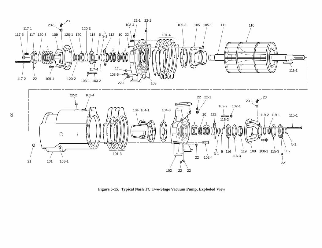
Figure 5-15. Typical Nash TC Two-Stage Vacuum Pump, Exploded View

23
AR- As Required* Minimum recommended spares
IndexNo. Qty Part Name
* 1 8 Rings Packing* 3 2 Slinger* 4 AR Shim* 5 2 Lip Seal* 5-1 1 Lip Seal* 10 2 Lantern Gland
21 1 Oriface Plug22 2 Pipe Plug22-1 7 Pipe Plug22-2 2 Pipe Plug22-3 4 Pipe Plug23 2 Grease Fitting101 1 Body
* 101-3 6 Floating Bearing End Body Gasket* 101-4 6 Fixed Bearing End Body Gasket
102 1 Floating Bearing End Head102-1 2 Gland Nut102-2 2 Gland Nut102-4 10 Floating Bearing End Head Screw103 1 Fixed Bearing End Head103-1 2 Gland Nut103-2 2 Gland Stud103-4 10 Fixed Bearing End Head Screw103-5 1 Fixed Bearing End Head Screw104 1 Floating Bearing End Cone104-1 8 Cone Screw
* 104-3 1 Cone Gasket105 1 Fixed Bearing End Cone105-1 8 Cone Screw
IndexNo. Qty Part Name
* 105-3 1 Cone Gasket108 1 Floating Bearing Bracket108-1 4 Floating Bearing Bracket Screw109 1 Fixed Bearing Bracket109-1 4 Fixed Bearing Bracket Screw110 1 Rotor111 1 Shaft111-1 1 Floating Bearing End Shaft Key112 2 Gland Assembly115 1 Floating Bearing Outer Cap115-1 4 Outer Cap Screw115-2 4 Outer Cap Nut
* 115-3 1 Outer Cap Gasket116 1 Floating Bearing Inner Cap
* 116-3 1 Inner Cap Gasket117 1 Fixed Bearing Outer Cap117-1 3 Outer Cap Screw117-2 4 Outer Cap Screw
* 117-3 1 Outer Cap Gasket117-4 4 Outer Cap Nut117-5 1 Outer Cap Nameplate118 1 Fixed Bearing Inner Cap
* 119 1 Floating Bearing* 119-1 1 Floating Bearing Locknut* 119-2 1 Floating Bearing LockWasher* 120 1 Fixed Bearing* 120-1 1 Fixed Bearing Locknut* 120-2 1 Fixed Bearing Lockwasher* 120-3 2 Fixed Bearing Ring Gasket
Legend for Figure 5-15

Bulletin No. 950-A2/97 Nash U.S., A division of THE NASH ENGINEERING COMPANY, Trumbull, CT 06611-1330
SALES & SERVICEINTERNATIONALU.S.A., Trumbull, ConnecticutThe Nash Engineering Company9 Trefoil DriveTrumbull Connecticut 06611-1330203-459-3900, Fax 203-459-3988
Australia, Smithfield, NSWNash Vacuum SystemsTel: (61) 02-725-5199Fax: (61) 02-725-5128
Brazil, CampinasNash do Brasil Bombas Ltda.Tel: (55) 192 455833Fax: (55) 192 455773
England, Winsford, CheshireNash Engineering Co. G.B.Tel: (44) 606-594242Fax: (44) 606-551994
Finland, KarhulaA. Ahlstrom CorporationTel: (358) 52 229 1111Fax: (358) 52 63958
Germany, OberuselNash Pumpen, G.m.b.H.Tel: (49) 6171-58830Fax: (49) 6171-59196
Japan, TokyoNash International CompanyTel: (81) 3 3449 0771Fax: (81) 3 3449 0746
Korea, SeoulNash Korea Ltd.Tel: (82) 2 786-1854Fax: (82) 2 786-1853
NetherlandsNash BeneluxTel: (31) 75 6470170Fax: (31) 75 6470175
Southeast Asia, SingaporeNash International CompanyTel: (65) 861-6801Fax: (65) 861-5091
South Africa, WadevilleVac-Cent Services (Pty) Ltd.Tel: (27) 11-8271536Fax: (27) 11-8273590
Sweden, StockholmNash Hytor ABTel: (46) 8 444 5470Fax: (46) 8 444 5474
CHEMICAL DIVISION SALESDivision HeadquartersElizabeth, PennsylvaniaTel: 412-384-3610Fax: 412-384-4880
Alabama, BirminghamNash U.S.205-951-2721, Fax 205-951-2724
California, Los AngelesNash U.S.714-573-4949, Fax 714-573-1291
Illinois, ChicagoNash U.S.630-241-7300, Fax 630-241-7313
New Jersey, BelmarNash U.S.908-681-4726, Fax 908-681-1544
Ohio, ClevelandNash U.S.216-934-1491, Fax 216-934-1492
Texas, HoustonNash U.S.713-821-9514, Fax 713-821-9012
GENERAL INDUSTRIAL SALESDivision HeadquartersTrumbull, Connecticut
Tel: 203-459-3716Fax: 203-459-3921
California, Los AngelesNash U.S.714-573-4949, Fax 714-573-1291
Missouri, St LouisNash U.S.314-298-8843, Fax 314-298-1818
North Carolina, CharlotteNash U.S.704-892-8824, Fax 704-892-6623
New Jersey, WarrenNash U.S.908-903-0359, Fax 908-903-0787
Ohio, ClevelandNash U.S.513-777-8237, Fax 513-777-8239
U.S. PAPER DIVISION SALESDivision HeadquartersClearwater, Florida
Tel: 813-539-8811Fax: 813-539-7552
Alabama, BirminghamNash U.S.205-991-0488, Fax 205-991-5664
Michigan, DetroitNash U.S.810-851-3203, Fax 810-851-3561
North Carolina, CharlotteNash U.S.813-539-8811, Fax 813-539-7552
Pennsylvania, ScrantonNash U.S.717-836-9924, Fax 717-836-9925
Texas, HoustonNash U.S.713-358-3561, Fax 713-358-3571
Wisconsin, AmherstNash U.S.715-824-5001, Fax 715-824-5003
U.S. POWER DIVISION SALESDivision HeadquartersElizabeth, PennsylvaniaTel: 412-384-3610Fax: 412-384-4880
Connecticut, TrumbullNash U.S.203-459-3639, Fax 203-459-3988
Missouri, Lee’s SummitNash U.S.816-478-4520, Fax 816-478-4633
California, Los AngelesNash U.S.714-573-4949, Fax 714-573-1291
U.S. REPRESENTATIVESArkansas, Little RockWoodbury-Beach Company501-663-9421, Fax 501-666-5603
Colorado, EnglewoodJ.F. Ronco and Associates303-796-7781, Fax 303-796-7783
Florida, DunedinMonarch Engineered Systems, Inc.813-781-1818, Fax 813-781-1618
Georgia, AtlantaE.W. Klein & Company404-256-9200, Fax 404-256-3471
Hawaii, Kailua, OahuCBC Inc.808-263-8838, Fax 808-261-4778
Illinois, DecaturBRI, Inc.217-864-3402, Fax 217-864-4036
Kentucky, Calvert CityBRI, Inc.502-395-4942, Fax 502-395-4943
Louisiana, New OrleansE.L.I. Inc.504-739-2470, Fax 504-739-2484
Massachusetts, BostonQuantum Engineering Co.617-740-8008, Fax 617-740-8228
Minnesota, MinneapolisEdelmann & Associates Inc.612-559-7867, Fax 612-559-9403
Missouri, St. LouisBRI, Inc.314-227-2535, Fax 314-227-2151
Oklahoma, TulsaMyers-Aubrey Company918-622-3500, Fax 918-628-0349
Oregon, PortlandCourtney & Nye Inc.503-693-1221, Fax 503-640-8424
Pennsylvania, PhiladelphiaThe Sherman Engineering Co.215-340-5300, Fax 215-340-5305
Tennessee, MemphisT.J. O’Brien Engineering Co.901-274-9011, Fax 901-725-0871
Utah, Salt Lake CityC. H. Spencer & Company801-975-0300, Fax 801-972-5216
Virginia, RichmondThe Hawkins-Hamilton Company804-323-0553, Fax 804-323-4185
SALES & SERVICE - CANADAAlberta, Calgary
General Equipment Ltd.403-252-9941, Fax 403-259-6975
Alberta, EdmontonGeneral Equipment Ltd.403-423-4488, Fax 403-423-4491
British Columbia, VancouverGeneral Equipment Ltd.604-876-8881, Fax 604-876-1048
Manitoba, WinnepegGeneral Equipment Ltd.204-453-4745, Fax 204-453-4778
Ontario, Toronto (Mississauga)S.A. McLernon Inc.905-678-2825, Fax 905-678-6133
Quebec, MontrealS.A. McLernon Inc.514-381-7291, Fax 514-381-2339
Saskatchewan, SaskatoonGeneral Equipment Ltd.306-244-2440, Fax 306-244-2770
SALES & SERVICE - MEXICORepresentaciones y Procesos Ind.Tel: (52) 5 543-5492Fax: (52) 5 523-5372
U.S. SERVICE CENTERSAlabama, Birmingham
Nash U.S.205-951-2721, Fax 205-951-2724
Illinois, ChicagoNash U.S.630-241-7300, Fax 630-241-7313
Missouri, St. LouisNash U.S.314-298-8383, Fax 314-298-1818
New York, AlbanyNash U.S.
518-862-0094, Fax 518-862-0097Ohio, Cleveland
Nash U.S.216-871-9505, Fax 216-871-9508
Texas, HoustonNash U.S.713-821-9514, Fax 713-821-9012
Washington, VancouverNash U.S.360-694-9557, Fax 360-694-9574
U.S. PARTS ORDERSSt. Louis, Missouri
1-800-770-6274