Embed Size (px)
Citation preview

NASA’S SPACE LAUNCH SYSTEM TRANSITIONS FROM DESIGN TO PRODUCTION
Bruce R. Askins
SLS Infrastructure Management Lead
Dr. Kimberly F. Robinson
Strategic Communications Lead
NASA Marshall Space Flight Center
Figure. I: Artist rendering of SLS launches from NASA’s Kennedy Space Center.
ABSTRACT
NASA’s Space Launch System (SLS) successfully completed its Critical Design Review (CDR) in 2015, a major milestone on the journey to an unprecedented era of exploration for humanity. CDR formally marked the program’s transition from design to production phase just four years after the program’s inception and the first such milestone for a human launch vehicle in 40 years. While challenges typical of a complex development program lie ahead, CDR evaluators concluded that the design is technically and programmatically sound and ready to press forward to Design Certification Review (DCR) and readiness for launch of Exploration Mission 1 (EM-1) in the 2018 timeframe.
Statement A: Approved for public release; distribution is unlimited.
DESTRUCTION NOTICE - For classified documents, follow the procedures in DoD 5200.22-M, National Industrial Security Program Manual, Chapter 5, Section 7. For unclassified, limited documents, destroy by any method that will prevent disclosure of contents or
reconstruction of the document.Statement C: Distribution authorized to U.S. Government agencies and their contractors; Critical Technology; 5/5/2015. Other requests for this document shall be referred to NASA Marshall Space Flight Center
Huntsville, AL 35801.
https://ntrs.nasa.gov/search.jsp?R=20160006976 2018-05-30T08:31:35+00:00Z

SLS is prudently based on existing propulsion systems, infrastructure and knowledge with a clear, evolutionary path as required by mission needs. In its initial configuration, designated Block 1, SLS will a minimum of 70 metric tons (t) (154,324 pounds) of payload to low Earth orbit (LEO). It will evolve to a 130 t (286,601 pound) payload capacity by upgrading its engines, boosters, and upper stage, dramatically increasing the mass and volume of human and robotic exploration while decreasing mission risk, increasing safety, and simplifying ground and mission operations. CDR was the central programmatic accomplishment among many technical accomplishments that will be described in this paper. The government/industry SLS team successfully test-fired a flight-like five-segment solid rocket motor, as well as seven hotfire development tests of the RS-25 core stage engine. The majority of the major test article and flight barrels, rings, and domes for the core stage liquid oxygen, liquid hydrogen, engine section, intertank, and forward skirt were manufactured at NASA’s Michoud Assembly Facility in New Orleans, Louisiana. Renovations to the B-2 test stand for stage green run testing were completed at NASA’s Stennis Space Center (SSC), near Bay St. Louis, Mississippi. Core stage test stands are reaching completion at NASA’s Marshall Space Flight Center in Huntsville, Alabama. The modified Pegasus barge for core stage transportation from manufacturing to testing and launch sites was delivered to SSC. The Interim Cryogenic Propulsion System test article was also completed. This paper will discuss these and other technical and programmatic successes and challenges over the past year and provide a preview of work ahead before the first flight of this new capability.
INTRODUCTION
NASA has set Mars as its long-range human exploration goal, as outlined in a 2015 report titled, “NASA’s Journey to Mars: Pioneering Next Steps in Space Exploration.”1 This effort is the result of the 2010 NASA Authorization Act and National Space Policy. It is an effort “made possible by a sustained effort of science and exploration missions beyond low Earth orbit with successively more capable technologies and partnerships,” the report states.
The report classifies the challenges leading to human Mars exploration into three regions: Earth Reliant, Proving Ground, and Earth Independent. The first region focuses on research and operations aboard the International Space Station and the growing capability of NASA’s commercial space transportation partners. The Proving Ground region encompasses operations in the Earth-moon region where NASA can develop and prove capabilities needed for humans to live and work much further away from Earth but still just days away from returning to the planet. The Earth Independent region reflects the technologies and capabilities necessary to travel to Mars for exploration of its moons or the Martian surface. To be successful, crews will have to be able to survive away from Earth for years and overcome challenges largely autonomously.
As part of that effort, NASA is developing core transportation capabilities in the form of the Space Launch System (SLS) and the Orion crew spacecraft. The following sections will provide an introduction to SLS and provide an overview of major technical progress to date.
THE SLS DESIGN
The SLS architecture is designed for deep space exploration involving highly-trained human explorers, large, one-of-a-kind payloads, and challenging, high-visibility missions of national and international significance. NASA traded literally thousands of design configurations before selecting the current design, which balances affordability, performance, safety, reliability, evolvability and overall mission objectives.
The design foundation for the future is the Block 1 configuration. (Figure I). Standing 98.2 meters (322 feet) tall and weighing 2.6 million kilograms (5.75 million pounds) fully fueled, the Block 1 will launch a minimum of 70 t into low Earth orbit – significantly greater capability than any existing launch vehicle. The basic elements are the core stage, four RS-25 engines powered by liquid hydrogen (LH2) and liquid oxygen LOX), and a pair of solid rocket boosters. Liftoff thrust is in excess of 3.6 million kilograms (8 million pounds). The engines and boosters are derived from space shuttle main propulsion. In fact, early SLS missions will use remaining engines and
booster case hardware from the Space Shuttle Program. The upper stage for EM-1 will be the Interim Cryogenic Propulsion Stage (ICPS), derived from the existing Delta Cryogenic Second Stage (DCSS). It is powered by the Aerojet Rocketdyne RL-10 B-2 engine producing 24,750 pounds of thrust. Vehicle layout is shown in Figure II.
Figure II: Expanded view of major SLS components
The first SLS mission will be Exploration Mission 1 (EM-1). Scheduled for late 2018, EM-1 will serve as an initial test of the SLS, ground and mission infrastructure, and the first deep space test of the Orion crew vehicle, which will be launched into an orbit beyond the moon. The flight will also accommodate 13 suitcase-sized secondary science payload that will be launched from the Launch Vehicle Stage Adapter (LVSA) en route to the moon.
Block 1 is designed to evolve to a Block 2 configuration with a payload of 130 t to LEO through
the use of upgraded main engines, advanced boosters, and a new upper stage. (Figure III) SLS’ unprecedented payload mass and volume offer mission planners larger payloads, faster trip times, simpler design, shorter design cycles, and greater opportunity for mission success.

Figure III: Expanded view of major SLS components
The SLS Program was officially activated in 2011 at NASA’s Marshall Space Flight Center, in
Huntsville, Alabama. Since that time, the nationwide SLS government/industry team has made significant progress. Completing Critical Design Review (CDR) in 2015, the program now has qualification and flight hardware for every element. The following pages will touch on the major accomplishments to date and the work ahead in 2016.
CORE STAGE
The SLS core stage is a new design that accommodates the existing RS-25 engine and 5-segment solid rocket booster derived from the space shuttle. The core stage measures 212 feet tall and 27.6 feet in diameter. In addition to its liquid hydrogen (LH2) and liquid oxygen (LOX) tanks which hold 2.1 million pounds of propellants, core stage primary structures also include its engine section, intertank section and forward skirt. It also contains the flight avionics, including computers and software, housed in the forward skirt. The engine section houses four RS-25s, compared to the shuttle’s three engines. The booster-to-core attach struts are spaced slightly further apart on the core with thrust structures located in the intertank and engine section.
The stage is designed by The Boeing Company and built at NASA’s Michoud Assembly Facility (MAF) in New Orleans, Louisiana, once used for both Saturn and shuttle manufacturing. Engine and stage green run testing is performed at Stennis Space Center. The A-1 stand was refurbished to conduct single engine testing, while the B-2 stand is undergoing modifications and upgrades to support core stage green run testing with a complete four-engine cluster.
Much of the major stage welding and assembly has been consolidated into six major tools: the
Circumferential Dome Weld Tool, Gore Weld Tool, Enhanced Robotic Weld Tool, Vertical Weld Center, Segmented Ring Tool, and Vertical Assembly Center (VAC).2

The VAC is the world’s largest spacecraft assembly tool, supporting all circumferential friction stir welds required to manufacture propellant tanks, engine sections and forward skirts, while the intertank is a bolted structure. The manufacturing route to flight hardware production involves several steps. “Weld schedule transfer” involves sample panel welds to confirm weld head speed, welding rate, and other details. Following that step is manufacturing of Weld Confidence Articles (WCAs), which are “flight-like” structures that are welded, and then have sections of the welds cut out and tested to ensure properties are sufficient to build flight hardware. Qualification articles for structural testing follow the WCAs before flight article welding begins.
Final assembly of major structures was delayed for several months in 2015 by the analysis
and recovery from the misalignment of the VAC. The 170-foot-tall welding tool was discovered to be out of alignment roughly two inches from bottom to top of the tower. As a result, tool was disassembled, corrected, and re-built. Welding resumed in late 2015 and progressed rapidly in 2016. At the time this paper was written, the engine section, LH2 and LOX weld confidence articles had completed welding on the VAC (Figure IV), and manufacturing is on track to complete all primary structural welding on structural test articles and the EM-1 core stage by the fall of 2016.3
Figure IV: LH2, LOX, and engine section weld confidence articles at MAF.
Following completion of the LH2 and engine section WCAs in early 2016, the LOX WCA was completed in March, clearing the VAC for welding of the engine section for the EM-1 core stage and the LH2 qualification unit for structural testing. The LOX WCA was the first article that required the performance of a closeout weld that attached an aft dome to a barrel, completing the welding of a full scale LOX tank consisting of two barrel sections and two domes. It will be used for thermal protection system (priming and foam application) development and verification activities.
Construction of test stands and fixtures were under way in 2015 and 2016 for structural testing of the LH2, LOX, engine section, intertank, and the Integrated Spacecraft Payload Elements (ISPE) test article. (Figure V) The new test facilities are scheduled for completion by the end of 2016.4

Figure.V: LOX (left) and LH2 (right) test stands under construction at MSFC
Vehicle flight software is being developed in-house at the Marshall Center. As of spring 2016,
the System Integration Test Facility- Development (SITF-D) facility was disassembled and assembly began on the System Integration Test Facility- Qualification (SITF-Q) (Figure VI).
Figure. VI: SLS flight avionics test setup at MSFC.
RS-25 ENGINE
The RS-25, commonly known as the Space Shuttle Main Engine (SSME), is ideally suited to the SLS application. It remains the highest performance, most efficient LOX/LH2 engine in its class. It performed successfully for more than 130 missions and accumulated more than 1 million seconds of ground and flight hotfire time. It was upgraded no less than five times to enhance

margin and reliability. Also noteworthy was the existence of 16 flown engines and two development engines available to SLS from the Shuttle Program.
The RS-25 produces more than 2.2 million Newtons (512,000 pounds) of vacuum thrust at 109
percent of rated power for SLS. It was routinely flown at 104.5 percent on the shuttles but was flight certified for 109 percent.
NASA, working with Aerojet Rocketdyne, embarked on an “adaptation” test program to verify
the engine would perform under SLS flight environments. Physically, the changes involved added insulation for the hotter base heating environment of a four-engine cluster and its proximity to the solid rocket boosters. It also involved a modern new engine control unit (ECU) and software. Operationally, the engine would face lower inlet temperatures due to pre-launch conditioning and proximity below the liquid hydrogen tank and higher inlet pressures due to the height of the LOX tank and greater acceleration loads.
SLS successfully conducted a series of seven hotfire tests at SSC. Development engine
#0525 amassed more than 3,700 seconds, demonstrating not only SLS performance requirements but providing a baseline for future tests using the refurbished A-1 stand, including a new thrust measurement system.5
Flight engine 2059, assigned to the Exploration Mission 2 (EM-2) mission, was the first hotfire engine test of 2016. (Figure VII) It served as a green run of the engine’s high pressure fuel turbopump and supported ongoing ECU development, as well as providing an additional baseline for the test stand using an engine with known performance.6 It will be replaced in the stand this year by the second development engine that will be used for additional adaptation testing, as well as green run testing of flight ECUs and software. Notably, the engine’s last hotfire was the STS-134 shuttle mission in May 2011.
Flight engine deliveries and flight ECU green run testing are both scheduled for late 2016.
These engines will feature the first use of additively manufactured parts on the RS-25 in the form of Development Flight Instrumentation (DFI) brackets.
Figure. VII: Two views of SLS flight engine testing at SSC.
While the available engine inventory will nominally support the first four SLS missions, NASA
began working with engine maker Aerojet Rocketdyne on development of an expendable version of the RS-25 that will also be more affordable. The new engine will be certified at 111 percent thrust. NASA expects to achieve significant cost reduction through deletion of reusability requirements and broader use of additively-manufactured components.

SOLID ROCKET BOOSTER
A pair of solid rocket boosters manufactured by Orbital ATK provides most of the SLS thrust for the first two minutes of flight. Each booster measures 54 meters (177 feet) long, 3.6 meters (12 feet) in diameter and produces 1.6 million Newtons (3.6 million pounds) of thrust. Of the booster’s total weight of 725t (1.6 million pounds), propellant accounts for 680 t (1.5 million pounds).
The booster’s solid rocket motor is based on the Space Shuttle four-segment motor modified
by the addition of a fifth motor segment for 20 percent more thrust. It also features new asbestos-free motor case insulation, a new motor grain design, an improved exhaust nozzle, and a new avionics system. In its SLS role, the previous booster’s parachutes, floatation devices and other recovery hardware have been discarded to make the booster expendable. Additionally, value stream mapping efforts have resulted in a streamlined manufacturing process for greater affordability.
Development five-segment motors have been test fired four times since 2009. The last and
most flight-like to date was Qualification Motor 1 (QM-1) in 2015 at the company’s test facilities in Promontory, Utah. The motor was heated to a mean bulk temperature of 32 degrees Celsius (90 degrees Fahrenheit), the high end of its specified operating range. The next test, QM-2, is planned for mid-2016, and it will be a test of the booster’s performance at a motor temperature of 4 degree Celsius (40 degrees F)7, the low end of its operating range.
During the development process, engineers discovered higher than expected incidence of
voids and un-bonds in the QM-1 aft motor segment insulation and propellant. Subsequent investigation involved hundreds of tests of material properties and a variety of subscale test articles. The source of the anomalies was traced to the new insulation, which was off-gassing after it was applied to the motor case walls and the segment was filled with warm solid propellant. The resulting bubbles led to voids and un-bonds in the insulation and propellant, which could have led to increased burning surface area and an overpressure in the motor. By adding a layer of the adhesive already used in case preparation and an additional thin sheet of the rubber insulation, the issue was successfully resolved. X-ray inspection of a modified segment lined with the new configuration showed the application was the most defect-free motor segment ever produced. Post-test inspection of QM-1 showed no additional issues. The design change and additional processing changes were implemented for the QM-2 motor production. SLS continues to develop a certification path for the motor with material and subscale testing and analysis ongoing through early 2017 to better understand the new material and configuration behavior.
The last of the five QM-2 motor segments was delivered to the Utah test site in early March
2016.8 Additionally, processing was under way on the motor case hardware for EM-1 at Orbital ATK’s Utah and Kennedy Space Center facilities with the first EM-1 segment cast scheduled for April 2016. Orbital ATK also delivered booster production simulation hardware to KSC to support booster hardware processing and support equipment checkout. (Figure VIII). Booster avionics qualification testing was scheduled to begin in April 2016 and run into early 2017. Avionics hardware will then undergo systems testing at Marshall Space Flight Center before delivery to Kennedy Space Center.
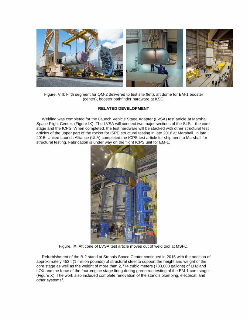
Figure. VIII: Fifth segment for QM-2 delivered to test site (left), aft dome for EM-1 booster (center), booster pathfinder hardware at KSC.
RELATED DEVELOPMENT
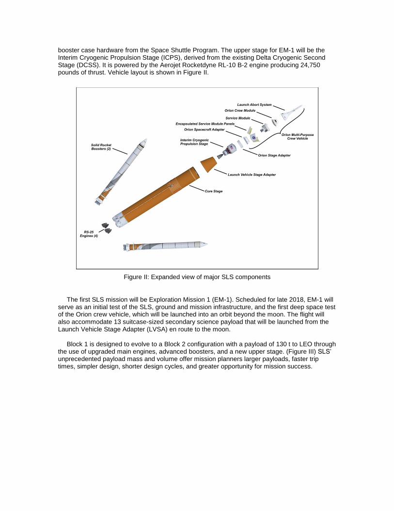
Welding was completed for the Launch Vehicle Stage Adapter (LVSA) test article at Marshall Space Flight Center. (Figure IX). The LVSA will connect two major sections of the SLS – the core stage and the ICPS. When completed, the test hardware will be stacked with other structural test articles of the upper part of the rocket for ISPE structural testing in late 2016 at Marshall. In late 2015, United Launch Alliance (ULA) completed the ICPS test article for shipment to Marshall for structural testing. Fabrication is under way on the flight ICPS unit for EM-1.
Figure. IX: Aft cone of LVSA test article moves out of weld tool at MSFC.
Refurbishment of the B-2 stand at Stennis Space Center continued in 2015 with the addition of
approximately 453 t (1 million pounds) of structural steel to support the height and weight of the core stage as well as the weight of more than 2,774 cubic meters (733,000 gallons) of LH2 and LOX and the force of the four-engine stage firing during green run testing of the EM-1 core stage. (Figure X). The work also included complete renovation of the stand’s plumbing, electrical, and other systems9.

Figure. X: Structural steel for core stage testing erected on B-2 test stand at SSC site.
The Pegasus barge was delivered to Stennis in 2015 (Figure XI) after the former shuttle
external tank barge was cut apart and a new section added to increase the total length from 79.2 meters (260 feet) to 94.4 meters (310 feet) to support the larger core stage. The expansion will allow Pegasus to ship core stage propellant tanks and other components to Marshall and Stennis for testing and ultimately to Kennedy Space Center for launch.
Figure. XI: Lengthened Pegasus barge delivered to SSC to support SLS core stage testing and transportation.
NASA and Boeing began development of an Exploration Upper Stage (EUS) with plans for a preliminary design review in late calendar year 2016. (Figure XII). The EUS will be powered by a

cluster of four RL-10-C-3 LH2/LOX engines, each producing more than 102,000 Newtons (23,000 pounds) of thrust in comparison to the ICPS single RL-10 B-2 producing more than 106,700 Newtons (24,000 pounds) thrust.10
Figure. XII: Artist concept of Orion powered by EUS.
SUMMARY AND CONCLUSIONS
SLS will be the world’s most powerful, versatile, and capable launch vehicle for meeting the unprecedented challenges of deep space exploration. NASA’s long-range goal is human exploration of Mars. The path to that exploration goes through ongoing operational experience aboard the International Space Station, development of commercial crew and cargo transportation, and development of capabilities in cis-lunar space. Development of the SLS heavy lift capability for launching the Orion crew vehicle, in-space stages, habitat modules, landers and other hardware is critical to that exploration. SLS manufacturing is underway on every major element. Work also is concurrently underway on the Orion crew vehicle and SLS launch facilities at Kennedy Space Center. When complete, SLS will open a new era of beyond-Earth human exploration, major new capabilities for robotic exploration, and scientific discovery for humanity
ACKNOWLEDGMENTS
The authors wish to acknowledge the assistance of ASRC Federal technical writer/editor Martin Burkey.
REFERENCES
1. NASA, NASA’s Journey to Mars: Pioneering Next Steps in Space Exploration, NP -2015-08-2018-HQ, http://go.nasa.gov/1VHDXxg, (Oct 2015).
2. NASASpaceflight.com, SLS: MAF receiving extraordinary machinery for the exploration rocket, https://www.nasaspaceflight.com/2013/06/sls-maf-extraordinary-machinery-exploration-rocket/ (2013)
3. NASA, Tools and Talent at Michoud to Complete SLS Core Stage Welding in 2016,
http://www.nasa.gov/exploration/systems/sls/michoud-to-complete-sls-core-stage-welding-in-2016 (2016)
4. NASASpaceflight.com, New SLS test stands rise out of the ground at Marshall,
https://www.nasaspaceflight.com/2015/11/new-sls-test-stands-rise-marshall/ (2015)
5. NASASpaceflight.com, Stennis completes first SLS RS-25 test series, prepares for
next engine, https://www.nasaspaceflight.com/2015/08/rs-25-completes-test-series-next-engine/ (2015)
6. Universe Today, NASA Test Fires SLS Flight Engine Destined to Launch Astronauts
Back To The Moon, http://www.universetoday.com/127839/nasa-test-fires-sls-flight-engine-destined-to-launch-astronauts-back-to-the-moon/ (2016)
7. Space.com, World’s Largest Solid Rocket Booster Fired in Ground Test for NASA,
http://www.space.com/28795-giant-solid-rocket-booster-nasa-test.html, (2015)
8. America Space, Next Qualification Booster for NASA’s SLS Rocket Taking Shape
for Spring 2016 QM-2 Test Fire, http://www.americaspace.com/?p=86571, (2016)
9. NASA, NASA Stennis Marks Milestone in Return to Deep-Space Missions,
http://www.nasa.gov/exploration/systems/sls/nasa-stennis-marks-milestone-in-return-to-deep-space-missions.html, (2015)
10. NASASpaceflight.com, NASA moves to enforce early switch to EUS for SLS,
https://www.nasaspaceflight.com/2016/02/nasa-enforce-early-switch-eus-sls/, (2016)