Embed Size (px)
Citation preview

(NASA-TM-111276) THE ROLE OF N96-18512STRUCTURAL DYNAMICS IN THE DESIGNAND OPERATIONS OF SPACE SYSTEMS:THE HISTORY, THE LESSONS, THE UnclasTECHNICAL CHALLENGES OF THE FUTURE(NASA. Marshall Space FlightCenter) 24 p G3/15 0099880
https://ntrs.nasa.gov/search.jsp?R=19960012275 2018-06-04T12:54:42+00:00Z
'' ' NASA-TM-111276
THE ROLE OF STRUCTURAL DYNAMICS IN THE DESIGN AND OPERATIONS OF SPACE SYSTEMS;THE HISTORY, THE LESSONS, THE TECHNICAL CHALLENGES OF THE FUTURE
Robert S. RyanGeorge C. Marshall Space Right Center
Marshall Space Flight Center, Alabama 35812
ABSTRACT
Structural dynamics and its auxiliary fields are themost progressive and challenging areas space systemengineering design and operations face. Aerospace sys-tems are dependent on structural dynamicists for theirsuccess. Past experiences (history) are colored withmany dynamic issues, some producing ground or flighttest failures. The innovation and creativity that wasbrought to these issues and problems are the aura fromthe past that lights the path to the future. Using thisillumination to guide understanding of the dynamicphenomena and designing for its potential occurrenceare the keys to successful space systems. Our greatparadox, or challenge, is how we remain indepthspecialists, yet become generalists to the degree thatwe make good team members and set the right priori-ties. This paper will deal with how we performed withacclaim in the past, the basic characteristics of struc-tural dynamics (loads cycle, for example), and thechallenges of the future.
I. INTRODUCTION
Structural dynamics is one of the most importantengineering disciplines of design. In aerospace, almostevery aspect of design is influenced by structuraldynamics. The primary goal of this paper is to providethe dynamicists with some insight or vision into thefuture. Influences from the past history of structuraldynamics in aerospace will provide the foundation forshaping the future and directing the vision.
This paper is divided into three areas: (1) the past,(2) the present, and (3) the future. A concluding sec-tion discusses some paradoxes that must be addressed.As an introduction, several special topics are reviewedbelow.
A. The Force Behind Dynamics
First, the unrelenting demand for high-specificstrength aerostructures results in very flexible ele-ments which propagate major dynamic concerns andproblems during design, verification, and operations.Said another way, high-performance requirements ofspace and aeronautic systems reduce margins andincrease sensitivities to uncertainties and parameter
Copyright © 1994 by the American Insutute of Aeronautics andAstronautics, Inc. No copyright is asserted in the United Staledunder Title 17, U.S. Code. Trie U.S. Government has a royalty-freelicense to exercise all rights under the copyright claimed herein forGovernment purposes. All other rights are reserved the copyrightowner.
variation. Control of dynamic response is therefore arapidly expanding technology with its unique set ofproblems.
B. Memories
Second, memories are the reminder of the impor-tance of structural dynamics. These memories includethe many experiences of Pogo, particularly the one thatresulted in shutting down the Apollo 13 S-II stagecenter engine. Also, the space shuttle Solid RocketBooster (SRB)/Solid Rocket Motor (SRM) ignitionoverpressure in retrospect was a little scary. TheHubble Space Telescope (HST) day/night terminatorexciting the system modes and creating pointing accu-racy errors was troublesome, although work-aroundswere devised. The recent replacement of the solararrays should eliminate the problem. The big role thattether dynamics has played in the design and operationsof the Tether Satellite System First Mission (TSS-1) isan interesting example. Also, structural dynamics is aconcern on all launch systems for gust response dynam-ics, transient dynamics of launch vehicles at lift-off,docking of spacecraft, and separation of system ele-ments. Flutter and buffet, along with modal stabilityand load relief, serve as reminders of the importance ofstructural dynamics. The major role that high-cyclefatigue has played in the development of reusableliquid propulsion engines through hot-fire testinginduced failures is another classic example. Memorieslight the pathway to the future.
C. Characteristics
Third, structural dynamics characterization has agood mathematical foundation. Structural dynamicresponses are manifest in several well-understoodways: (1) instability, (2) forced response, and (3)transient response. All of these are well formulatedmathematically. The problem engineers face in dealingwith dynamics is twofold: (1) modeling and verifyingthe structural dynamic characteristics and (2) predict-ing the imposed natural and induced environments withtheir variations.
Reference 1 says that "the essence of modeling, aswe see it, is that one begins with a nontrivial wordproblem about the world around us. We then grapplewith the not always obvious problem of how it can beposed as a mathematical question . . . One of thelessons learned is that there is no best model, onlybetter ones. The model is only a suggestive metaphor, aficu'on about the messy and unwieldy observations ofthe real world. In order for it to be persuasive, to
convey a sense of credibility, it is important that it notbe too complicated and that the assumptions that aremade be clearly in evidence. In short, the model mustbe simple, transparent, and verifiable."
D. Trades in the Design Process
Fourth, it is a truism that all design is a balancingact; therefore, in accomplishing the design tasks associ-ated with structural dynamics, many problems arise,trades must be accomplished, and compromises made.The nature of engineering design dictates that thisbalancing act must be based on knowledge, not only ofstructural dynamics, but of the total system. There-fore, structural dynamicists are faced with challengingbut exciting tasks.
Pye2 discusses the source of problems and thesecompromises. He talks about the source of problemsdealing with the manifestation and transfer of energy.He says, "Now whenever a change is made, by thepassage of energy . . . When you put energy into a sys-tem you can never choose what kind of changes shalltake place and what kind of results shall remain. . .All you can do, within limits, is to regulate theamounts of the various changes by design, ensuring thatat least you get the change you want along with otherswhich you don't. If you want some of this then youmust take some of that as well, even though you donot want it." Later he says, "The requirements fordesign conflict and cannot be reconciled. All designsfor devices are in some degree failures . . . The designeror his client has to choose to what degree and wherethere shall be failures . . ." So our job is always chal-lenged by trades. With this introduction, the next dis-cussion deals with the past.
II. THE PAST: PROBLEMS, CHALLENGES,CREATIVITY, AND INNOVATION APPLIED
The greatest thrill that I have had has been to seethe innovation, creativity, and common sense structuraldynamicists have exhibited when major dynamic prob-lems or issues have surfaced. Space exploration andaeronautical development, as well as the transportationindustry and other endeavors, are replete withexamples of these unexpected dynamic structuralresponses. Recently, I have been in the process of cate-gorizing and documenting problems I have dealt within space exploration for approximately the past 38years.3"6 Most cases are in the broad category ofdynamics. Our future demands that we must understandthe breadth and scope of dynamic manifestations andprevent or control their occurrences. In accomplishingthis, the dynamicist must also deal with a multitude ofinteractions such as fluid-structure, structural control,and aeroelasticity, to name a few. Structural dynami-cists have made a name for themselves in how theircreativity dealt with these issues. In this brief look atthe past, it is hoped that we can see the variety, beexcited, and accept the challenge that dynamics offers,and marvel in the creativity and innovation required for
their solutions, particularly where the brute-forcecomputational approach was not available.
A. The Jupiter Defense Missile fLate 1950's)
The Jupiter defense missile experienced a max-qfailure due to the closed-loop coupling between pro-pellant sloshing, rigid-body vehicle rotation, and thevehicle attitude control system. The original mathe-matical description of the problem was unable topredict this failure condition. To fix the failurerequired a better understanding of the system dynamicbehavior and component interactions, which in turnrequired improved math models and new test verifica-tion methods. Due to the complexity of the hydro-dynamic equations, it was not feasible to couple themwith the vehicle dynamics and control system. A singledegree of freedom mass, spring, and damper system wasconstructed that closely approximated the hydro-dynamic analytical results, and was added to the sys-tem describing equations with the attitude control sys-tem feedback. The second innovation was a subscalemodel and full-scale sloshing model tests. The full-scale dynamic test consisted of installing a Jupiterliquid oxygen (lox) tank full of water on a railroadcar and lightly bumping it against the track stop. Athird innovative solution was floating long cylindricalcans (commode float in one end of the perforatedcylinder, named beer cans), thus filling up the propel-lant surface and damping the liquid motion (fig. 1).The fourth innovation occurred after several successfulflights in which baffles were integrated with the pro-pellant tank stiffener ring frames to provide dampingwhich controlled the liquid dynamics while serving asstructural rings. The Guidance, Navigation, and Con-trol (GN&C) system was also part of the problem inthat the trajectory tilt program was a series of stepsthat increased the sloshing dynamics. A continuous tiltprogram was implemented thereby removing this exci-tation force.
B. The Saturn I and IB Program
The Saturn I and IB program, the testbed for theSaturn V Apollo program, had some unique problemsand solutions (fig. 2). The cluster of eight Redstonediameter tanks around a larger center tank presentedmany structural dynamic challenges. One problem washow to accurately model the tanks clustered with theupper supporting spider beam, providing the load pathfrom the first stage to the second stage. Finite elementcodes were not available. Computer capability was notextensive nor was testing capability in terms of today'sstandards. The innovative analytical modeling approachassumed clamped/hinged modes of the clustered tankscoupled to the rest of the system and the center tankand upper stage. This was done by writing the systemequations of motion using generalized coordinatesthrough a Lagrangian approach. This was the firstapproach to what developed later as modal coupling. Avery accurate system mode, in comparison to test

Cylindrical SkinSections
Oxidizer LineTunnels —i
Anti-SloshBaffles
Flight
Fittings
HeadFittings
LowerHead
• V
'>S:X-:&iZsJ& i-''':*'-:-.':.«'" •.-,:• >-.'>.<5 rrr- i H. •*:•: •••v- -.•«Xi$^\ •»'*^^;-V-A- ;.
Saturn V S-1C Fuel Tank Assembly
Typical Ring Baffles For Sloshing Floating Can Slosh Suppression Device
Fig. 1. Jupiter Slosh Suppression Techniques.
derived system modes, resulted using very few compo-nent modes; the secret being in the proper selection ofthe end conditions for the component models.
At this time, very few subroutines existed forsolving for the eigenvalue/eigenvector or root locusvalues. Engineers developed crude approaches using thegradients (slopes) of the characteristic equations. Com-plexity of the dynamics of the structure modelrequired verification. A scaled model was developedand tested at Langley Research Center, while theMarshall Space Flight Center conducted a full-scalestructural dynamic test. Water was used to simulatethe liquid propellant. Later, hydrogen was simulatedusing Styrofoam balls. During this test, the supportsystem (long cables) used to approximate the in-flightfree condition tuned up with the vehicle modes cloud-ing the vehicle modal data. Two-by-fours were tied tothe middle of the cables detuning these suspensionmodes, thus producing good vehicle modal data.
During data evaluation of the Saturn I vehicledynamic test, attempts were made to filter the supportmode effects from the vehicle modes. This led to anerroneous set of modes that were unstable whencoupled with the control system. The first Saturn Iflight was held 2 weeks to sort this problem out. Thestory of this concern appeared in Fortune magazine7
with descriptive stories of the potential dynamicsdisaster. All problems were sorted out and the flightwas flawless.
C. The Saturn V (Late 196Q's)
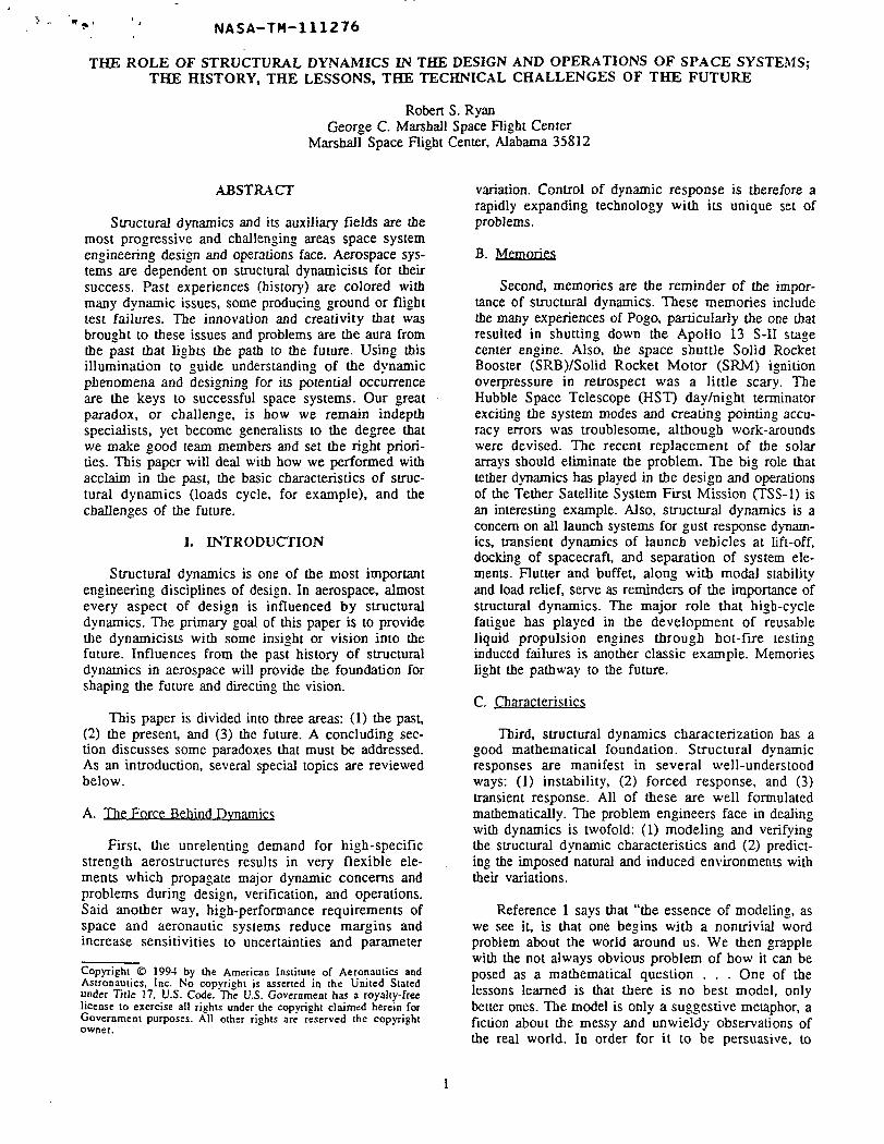
1. Pogo. The Saturn V had many interesting prob-lems. Pogo topped the list. Pogo occurred on the firststage of the second Saturn V launch. It was due to aredistribution of the mass in the simulated Apollo cap-sule and command module, changing the gain of thefirst longitudinal mode and causing it to tune with thefluid modes (fig. 3). The fix was simple: use a wrap-around accumulator on a duct to detune the fluid modesfrom the structural modes. Early on, the second stageS-II had nonlinear Pogo oscillations which were notconsidered a problem. As the program progressed, thePogo got worse. Because the main coupling was thecenter engine and excess performance was present, itwas decided to shut this engine down in flight prior tothe time Pogo was being observed and to install acenter engine cutoff if Pogo amplitude occurred whilethe engine was running. Fortunately this was done. OnApollo 13, the ill-fated flight for other reasons, Pogooccurred early in the S-II stage burn, shutting downthe center engine. The amplitude, in all probability,was large enough to yield the thrust frame, even withthe cutoff approach, due to the sharpness of the insta-bility (fig. 4).
In order to deal with the Pogo problem, manyinnovative test and analysis tools were developed inaddition to the use of a Pogo working group, the fore-runner of today's concurrent engineering teams. Hydro-elastic testing of the tanks, acoustical testing of theducts containing fluid, and nonlinear pump tests

NorthAmerican
Launch Escape System
Command Module
Service Module
SpacecraftLem Adapter
IBM Instrument Unit
DouglasS-IVB
2nd Stage
ChryslerS-1B
1 st Stage
APS Module
J-2 Engine Nozzle
LOX Tank
Fuel Tank
H-1 Engine Nozzles
Reaction Motors
Propellant Tank
Helium Tank
Service ModulePropulsionEngine Nozzle
Hydrogen Tank
LOX Tank
Retro Rocket
224ft.
Fig. 2. Saturn 1B.

S/C WEIGHT COMPARISON (1.01
COMPONENT 501 502
LES 9700C/M 12000S/M 39700LM 29500
SO 100
FLIGHT TIME-SEC
50 -
_40I
I20
CROSS-BEAM STRUCTURAL.ACCELERATION FREQUENCY /
Fig. 3. AS-501/AS-502 First Mode Longitudinal Structural Dynamic Characteristics Comparison.
coupled with a scaled model test. Not only was a scalemodel of the total vehicle developed, but after theApollo 13 incident with the SLA panel failure andlateral/longitudinal coupling of the LEM response, adetailed scaled model of the LEM, Apollo servicemodule, and capsule was built and tested. This scaledmodel incorporated the scaling of manufacturing toler-ances. This was necessary due to the nonlinear effectsof gaps and joints changing the mode shapes and fre-quencies—a lesson learned in early scale model testing.In order to simulate the mass effects of hydrogen inthe tank during full-scale testing, the hydrogen tankwas filled with Styrofoam balls. A hydrodynamic(fluid bearing) support system was developed to getfree-free conditions.
/PfPROPULSIONFREQUENCY
LOX SUMP:CELERATION
/INBOARD ENGINE*"'-CHAMBER PRESSURE
19.0
- 1B.5
O
1B.O m
h".5
17.0
496 500 606 510 516 620 525 530 63S
RANGE TIME ISEC)
Fig. 4. AS-504 S-ll Stage Pogo.
were conducted in order to get linear and nonlineardynamic characteristics. In order to simulate the non-linear coupled system of structure, fluid, and propul-sion, a hybrid computer was used where the nonlinearelements were formulated on the analog side while thelinear elements were simulated on the digital side. Agood correlation was obtained with flight data (fig. 5).The fix was simple in concept, using an accumulator onthe feed line; however, the accumulator had to be filledat engine start, thereby causing the frequencies tomomentarily tune. This turned out not to create aproblem, and all subsequent flights were Pogo-free.
2. Scaled Model Test. Dynamic testing of the all-up Saturn V vehicle was a major effort and was
3. Controls and Coupling. The controls commu-nity developed and implemented the load relief tech-nology using accelerometers instead of external flow-mounted angle-of-attack meters. Elastic body (modal)response and stability was a major issue and requiredthe development of approaches to integrate structuraldynamics and control. A natural extension was thedevelopment of modal suppression (in the aeronauticsside, this was called ride control) techniques which, inconjunction with rigid-body load relief, not onlyreduced tie basic aerodynamically induced loads, butalso reduced the response due to elastic-body dynamicsand wind gust and turbulence excitation. Years later,this technology evolved into active flutter suppressionand aeroelastic tailoring.
The long, slender configurations raised many ques-tions in terms of this control/structural/aerodynamic
FLIGHT TRACE
I i . •
80 -i
A PCCHAMBERPRESSURE 0 -
-80 J
SIMULATED
S-ll FLIGHT TIME (SEC)
Fig. 5. S-ll Stage Pogo.
system due to potentially strong couplings (aero-elasticity). Technology evolved based on aircraftexperience to deal with static aeroelastic effects, gustpenetration, and the hammerhead effects. The technol-ogy involved not only analytical models, but also scalemodel wind tunnel testing.
4. Wind Technology. Wind biasing technologymatured and became a viable operational tool foradding flexibility and increasing margins. All thesetechnologies required developing and maturing tech-nologies in several additional areas:
1. Measuring and quantifying the atmosphericcharacteristics in terms of wind speed, shears,gust, and turbulence
2. Statistical data evaluation techniques, tools,and models
3. Structural dynamic characterization ofcomplex, multibody systems.
In the atmospheric characterization arena, theJimspbere balloon and better radar tracking technologydeveloped, allowing the description of the windsincluding gusts in the 25-m range. During this time,the synthetic wind profile matured to incorporate notonly wind speed, but also shear and gust. Threeapproaches were developed to handle the gust: (1) 9-msquare wave that was tuned to match the vehicle lowermode frequencies, (2) tuned sine wave gust whereamplitude varied with frequency, and (3) power spec-tral density formulation of turbulence. A month-by-month statistically significant sample of what werecalled real wind profiles was developed through a
comprehensive wind sounding program. These windprofiles were used to run Monte Carlo elastic vehiclecontrol response analysis using a high-speed repetitiveanalog computer. This system not only allowed a sta-tistical characterization of the vehicle wind response,but also produced valid quantification of the syntheticprofile approach for vehicle wind simulation.
One aside in terms of the synthetic wind profiledevelopment was the question of how to properlycombine the wind speed, shear, and gust and do a con-ditional probability assessment. Putting together 3ovalues of each was obviously too severe. Helmut Horncame up with the idea of conditionally dealing with a3a wind speed root sum squaring the 3a shear and gustwith the wind speed. William Vaughn was fundamen-tal in this also as well as developing the wind sound-ing technology. Because the atmospheric (winds) hadpreferred monthly directional and speed characteristics,the technology evolved for biasing the launch trajec-tory to the monthly mean wind, reducing wind inducedstructural loads and increasing the launch probabil-ity/flexibility. Some performance loss occurred due. tothe path errors introduced in order to reduce angle ofattack. The performance people would have raised the(+a) value in the atmosphere, and the loads/controlspeople could not allow the unrestricted +a. The com-promise was to raise the nose (reducing a) at a profilestarting at an agreed-to time, trading performance lossfor reduced loads. No closed-loop guidance was used inthe atmosphere for the same reason.
The synthetic wind profile approach did presentone problem in that the vehicle response to winds hadto consider variation of other vehicle parameters(control, aerodynamics, propulsion, structures) in

addition to winds, and also the stress analysts anddesigners needed time-consistent data in order to per-form adequate analysis. Judson Lovingood developedthe A-factor approach which took the root-sum-squared (RSS'ed) responses from sensitivity analysis toproduce scalings of the parameter variations that, whenapplied, produced a time response analysis with thesame peak as the RSS'ed sensitivity analysis.8
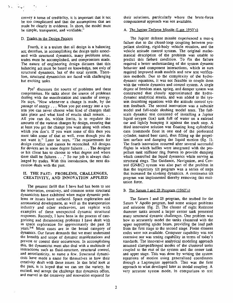
5. Lift-Off Loads. The Saturn V had a potentiallylarge loads problem at lift-off due to the stored energyresulting from holding the vehicle down until theengines were at full thrust (engine health checkout sys-tem). A system was developed which created a softrelease by extruding the holddown bolt through softmetal, thus greatly reducing the vehicle lift-off loads(figs. 6A and 6B).
D. The Space Shuttle (Late 1970\ to Present')
The space shuttle design, development, and verifi-cation involved many dynamic issues, not the least ofwhich were fatigue and fracture problems, rotor-dynamic issues in the main engine, and a highly dynamiclaunch vehicle at lift-off plus high rigid body dynamictransient loads at maximum dynamic pressure. Inte-grated and multidisciplinary analysis was a key tech-nology in that control, performance (flight mechanics),loads, and thermal were highly coupled. Many inno-vations to accomplish this task were developed tosupport the program.
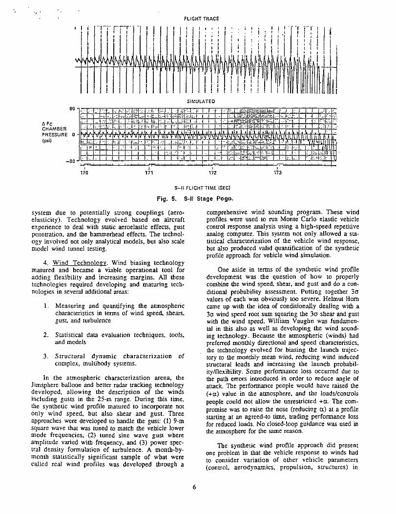
1. Ignition Overpressure. Understanding thephysical phenomena of ignition overpressure anddesigning a suppression approach was a key technologyarea, as well as the innovation used in arriving at a fix.Testing of a 6.4-percent scale model of the shuttlepropulsion and its enhancement allowed both thephysical understanding and the assessment of the waterspray suppression and water troughs. The scaled testsshowed that water, when injected into the flow,reduced the wave formation and, if contained, presenteda shield which blocked the overpressure waves. A sig-nificant outcome from these tests was the baselining ofwater troughs as an insurance solution to the waterspray injections (figs. 7A and 7B).
2. Space Shuttle Main Engine CSSME). The SSME,with its high-performance requirements (454 ISP) anda 55-mission life coupled with geometric and weightconstraints, developed fatigue and fracture issues thatled to the development or enhancement of several tech-nologies. Dealing with lifetime issues required adetailed characterization of both structural models andenvironments which pushed development of computa-tional fluid dynamics (CFD's) technology. This tech-nology started, evolved, and matured in 10 years,greatly enhancing the maturity of the SSME. Also,finite element structural analysis matured during thistime. Verification of environments required the devel-opment of special instrumentation for flows, acoustics,
Tail Service Position
Tail ServiceMast No. 3
FinB
M' 67\ Saturn V Control Release Locations
\0
ControlRelease
i Mechanisms
Eng. Fairing 2-75
AirScoop
Hold Down
View A-A
STA 8.75
FinD Cross-HatchedArea RepresentsLitt-OH ControlMechanism Envelope
Fin ATail ServiceMast No. 2
Fig. 6A. SV Soft Release.
Detail of ControlRelease Pin
Fig. 6B. SV Soft Release.
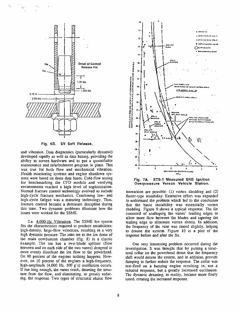
and vibration. Data diagnostics (particularly dynamic)developed rapidly as well as data basing, providing theability to screen hardware and to put a quantifiablemaintenance and refurbishment program in place. Thiswas true for both flow and mechanical vibration.Health monitoring systems and engine shutdown sys-tems were based on these data bases. Cold-flow testingfor benchmarking the CFD models and verifyingenvironments reached a high level of sophistication.Normal fracture control technology evolved to includehigh-cycle fracture mechanics. Combining low- andhigh-cycle fatigue was a maturing technology. Thus,fracture control became a dominant discipline duringthis time. Two dynamic problems illustrate how theissues were worked for the SSME.
2.a. 4.0QO-Hz Vibration. The SSME lox systemfits the characteristics required to produce instabilities:high-density, large-flow velocities, resulting in a veryhigh dynamic pressure. The inlet tee to the lox dome ofthe main combustion chamber (fig. 8) is a classicexample. The tee has a two-blade splitter (flowbetween and on each side of the two vanes) designed tomore evenly distribute the lox flow to the powerhead.On 90 percent of the engines nothing happens. How-ever, on 10 percent of the engines a high-frequency,high-amplitude (4,000 Hz, 100 g's) oscillation occurs.If run long enough, the vanes crack, detuning the struc-ture from the flow, and eliminating, or greatly reduc-ing, the response. Two types of structural elastic flow
nil
Fig. 7A. STS-1 Measured SRB IgnitionOverpressure Versus Vehicle Station.
interaction are possible: (1) vortex shedding and (2)flutter-type instability. Extensive effort was expandedto understand the problem which led to the conclusionthat the basic instability was essentially vortexshedding. Figure 9 shows a typical response. The fixconsisted of scalloping the vanes' leading edges toallow more flow between the blades and tapering thetrailing edge to eliminate vortex sheets. In addition,the frequency of the vane was raised slightly, helpingto detune the system. Figure 10 is a plot of theresponse before and after the fix.
One very interesting problem occurred during theinvestigation. It was thought that by putting a struc-tural collar on the powerhead dome that the frequencyshift would detune the system, and in addition, providedamping to further reduce the response. The collar wastest-fired on a buzzing engine resulting in, not areduced response, but a greatly increased oscillation.The dynamic detuning, in reality, became more finelytuned, creating the increased response.

12" DIAPIPE
TO SSME HOLEv
SRB AFT SKIRT,
WATER BARRIER110 BAGS/PRIMARY HOLE)
18" 01A PIPENEW SRB OVERPRESSUREWATER SPRAY HEADER
24" DIAPIPE
8"OIAPIPE
MLP BLASTSHIELD
12" DIA PIPE
24" DIAPIPE
SRB SUPPORT PORT
•.18" DIA PIPE
WATER BARRIER120 DAGS/SECONDARY HOLE)
MLPDECK 03U" DIA PIPE
Fig. 7B. Overpressure Mods STS-2 Configuration.
.60
VIEW A
Fig. 8. Engine 2116 Main Injector Splitter Vane Cracks.

76.0
G RMS(3-PT)
(3-101
ENGINE 2025 - TEST 750-262
4060.0
FHEQHZ
(3-10)
FREQUENCY (3960-4060 HZ)
3050.0
LOX8N
~4000 H2^ PHENOMENON
.«/
.0 20.TIME (SEC)
' 260.041
Fig. 9. 4,000-Hz Vibration Anomaly Gimbal Bearing Longitudinal Accelerometer.
TEST 7500262 S+140 109%1.0E+003p
N
Iwo
(3-10)1.0E-002
4025.0 662.054412.5 2.092012.5 1.594075.0 1.293687.5 0.913562.5 0.874312.5 0.813737.5 0.764262.5 0.763850.0 0.74
BW =12.5AUGS = 8COMP = 97.35
0. 5000FREQUENCY (Hz)
Fig. 10. Spectrum of Gimbal Bearing Acceferometer.
10
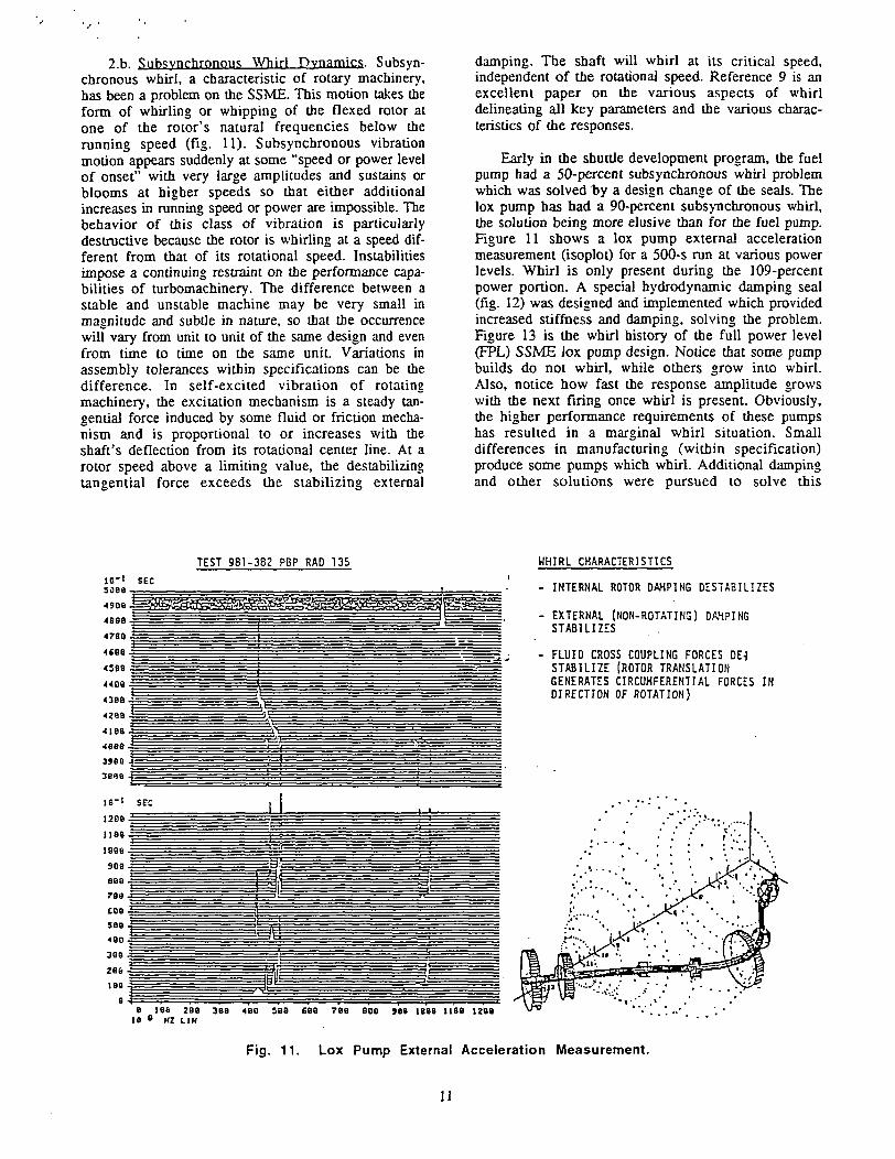
2.b. SAsynchronous Whirl Dynamics. Subsyn-chronous whirl, a characteristic of rotary machinery,has been a problem on the SSME. This motion takes theform of whirling or whipping of the flexed rotor atone of the rotor's natural frequencies below therunning speed (fig. 11). Subsynchronous vibrationmotion appears suddenly at some "speed or power levelof onset" with very large amplitudes and sustains orblooms at higher speeds so that either additionalincreases in running speed or power are impossible. Thebehavior of this class of vibration is particularlydestructive because the rotor is whirling at a speed dif-ferent from that of its rotational speed. Instabilitiesimpose a continuing restraint on the performance capa-bilities of turbomachinery. The difference between astable and unstable machine may be very small inmagnitude and subtle in nature, so that the occurrencewill vary from unit to unit of the same design and evenfrom time to time on the same unit. Variations inassembly tolerances within specifications can be thedifference. In self-excited vibration of rotatingmachinery, the excitation mechanism is a steady tan-gential force induced by some fluid or friction mecha-nism and is proportional to or increases with theshaft's deflection from its rotational center line. At arotor speed above a limiting value, the destabilizingtangential force exceeds the stabilizing external
damping. The shaft will whirl at its critical speed,independent of the rotational speed. Reference 9 is anexcellent paper on the various aspects of whirldelineating all key parameters and the various charac-teristics of the responses.
Early in the shuttle development program, the fuelpump had a 50-percent subsynchronous whirl problemwhich was solved by a design change of the seals. Thelox pump has had a 90-percent subsynchronous whirl,the solution being more elusive than for the fuel pump.Figure 11 shows a lox pump external accelerationmeasurement (isoplot) for a 500-s run at various powerlevels. Whirl is only present during the 109-percentpower portion. A special hydrodynamic damping seal(fig. 12) was designed and implemented which providedincreased stiffness and damping, solving the problem.Figure 13 is the whirl history of the full power level(FPL) SSME lox pump design. Notice that some pumpbuilds do not whirl, while others grow into whirl.Also, notice how fast the response amplitude growswith the next firing once whirl is present. Obviously,the higher performance requirements of these pumpshas resulted in a marginal whirl situation. Smalldifferences in manufacturing (within specification)produce some pumps which whirl. Additional dampingand other solutions were pursued to solve this
TEST 981-382 PBP RAD 135
soaa •
4908
SEC
44oa43BB
428B
41BB
4686
3988 |
3818
IB"'
1206 .
nee.198(5.
908 .
888 .
788-
C08 .
sea .
480 -
388 -
286 -
tea .
SEC
II
WHIRL CHARACTERISTICS
- INTERNAL ROTOR DAMPING DESTABILIZES
- EXTERNAL (NON-ROTATING) DAMPINGSTABILIZES
- FLUID CROSS COUPLING FORCES DE-|STABILIZE (ROTOR TRANSLATIONGENERATES CIRCUMFERENTIAL FORCES INDIRECTION OF ROTATION)
e 186 288 388 480 588 £88 788 BOB 989 1888 1188 128018 8 HZ LIH
Fig. 11. Lox Pump External Acceleration Measurement.
11

LeakageFlow
SmoothSurface
Seal Stator Part
TriangularPockets forRough StatorSurface
Rotor
Stator
Low Level Circulation(Couette Flow)Hinders Rotor Whirl
Seal Rotor Part
Note: ClearancesExaggerated
Fig. 12. Damping Seals.
H V I I O E KMI«l IC1>-_I
IllStonv O' MPQtf WITH WHIRL
ON sti nm
r^;'OIALTMT «-!_„,• MJ1
Ti**t » rrv istci — SrE
winni TIMI jsro— ~«>»
OMSCT TIM| JIC — . 2"""AM Cn HAM? (•/.) i ii
31 "| r-
30 -
osM Jt -
2
?• •
"*
k.
'
/
(o
r
" S 0 r*
R -
** **
v
s
\
t
*
N
\
/
V
; B
2
R
2
^
,
'
S
2
^s
•„
/
•v
•»
£
1000 IOC 1»
o o
M
-
m\
Vi''
;.
i X
sn
-
0D O O
a « s?o12
32 2
"~
c
X
-
sv]
•y
V\\\•
i
•V\VVK
\; J
2 2
9
ii
»i 1
\\v-\\^^x^SXXX KX
»"' IK
• • x SSS s
8 *7 2
s/yxaf-'xX
H/MP jwniAi "o. — 0303 son inn JIM zio« inn 2710
riv I3B*. . o .o^ O O M O ^*» *^c. ° °.
£ *1
PUMP rnwf — » arum
O
-
o
-1
•o
»
r^>
y7 7
;
2
a
2
S2
71
^\
s\
\i,a2
V
S,
•'.
I/
<
*•
<
£
s
\\\s
s
I-J
1-1
l-ll '
»3*1 • !»'»
i_5 • S 5 = = ? ', ? 2 ^s •. *-
721? mil 0107
• O « w t o « * O O O O.
;
I
:K
;
X
ex
2
I
i
2
:x
•" —
IM1
R X *S
**
-
o"
=0
•>t
•1t
~-0
*
.•>^;
0
-
'•
X ll
z
\s'••\
\
A i
X J i t ,
JJ« »<"•»' JJ"
o s . . - - o o o o . o : ; 5W> » *• «n K* * W " * * » ••
2 . -» (X! .
•CONIKDLIIRIOC«U'
Fig. 13. Lox Pump Whirl History.
12

problem. The concept and development of hydro-dynamic damping seals were the innovative solutions towhirl. George von Pragenau was the inventor.
Whirl is a very interesting and complexphenomenon. It is very destructive to the bearings,limiting life, and can lead to pump failures whichcould be catastrophic in nature. Although a classicproblem, treated extensively in literature, the rotarydynamic elements of the shuttle are the first of thenew breed of high-energy density, high-performancepumps. The high-pressure fuel pump, for example,develops a maximum of 75,000 hp in a space volume ofa 1-ft diameter and 2-ft length and weighs approxi-mately 250 Ib. Future engine systems will extendrotordynamics technologies even further.
E. Hubble Space Telescope (1980's to Present)
The prime technology driver for the HST was thevery high-pointing accuracy requirement. Several devel-opments and breakthroughs occurred, including theunderstanding and verification of the modal character-istics for both pointing control during operations andaccurate load predictions during ascent. Full-scale free-free dynamic tests were used in conjunction withdynamic impedance testing of the HST orbiter attachpoints. Impedance testing was a work-around that wassuccessful for HST due to the simple characteristics ofits trunion modes. Development is underway toattempt to broaden its application to more complexsystems. This technology has led to the development ofnew testing techniques for space systems involvingresidual flexibility approaches.
During HST operations, a very interesting dynamicproblem was experienced. In moving across the day-to-night or night-to-day terminator, the changing thermalconditions caused the solar array to snap, setting uplow-frequency dynamic oscillations that affect thepointing accuracy. This effect was reduced by a controllogic software change. During the repair mission, a newsolar array was installed to eliminate this problem.
The history of aerospace/aeronautical engineeringhas therefore had its share of the manifestations ofproblems; however, the ingenuity, creativity, andcommon sense brought to these problems are ourexamples for the future. This same innovative approachused to solve these problems prevented many moreproblems than those that occurred. Problem preventionis a major thrust of the future.
III. THE PRESENT
In recent years, the major practices or thrusts instructural dynamics have been in the analytical andcomputational arenas. Mathematically, the structuraldynamics field is well defined, notwithstanding thatthere are many open research areas. References 10through 20 provide several examples. The solutions ofdynamics response problems can usually be classified
into three categories: (1) stability/instability, (2)transients, and (3) forced response. Control-augmentedstructures still fall into these categories. The presentstate of structural dynamics is partially characterizedunder the following topics.
A. State-of-the-Art Practices in Structural Dynamics
1. Finite Element Modeling. Numerous codesexist for finite element modeling that include aplethora of element types, and that treat both thedynamics and statics of the structure. Some nonlinearcapability exists, as does fixed and animated graphics.Commercial codes such as NASTRAN, ANSYS,PATRAN, etc., are readily available and are univer-sally used. Finite element modeling is the norm forworking structural dynamics problems. Figure 14summarizes the state-of-the-art in modeling.
2. Integrated Analysis. Although typically westill practice the "dumping it over the fence" approachfrom one discipline area to the other, strides have beenmade in integrated analysis approaches.21 The effortthat Ben Wada has led in "smart" or "adaptive" struc-tures is one example. Also included are the works ofJunkins and others10 on structures/control interaction.Thermal, aeroelasticity, and structures/propulsioncoupling (Pogo) are all examples, as is the launchvehicle loads analyses. Figure 15 is a matrix of launchdesign illustrating the current approach showing inputsand outputs from each area (Martin Marietta generatedthis chart).
3. Environments Definition/Verification. Greatstrides have been made in dynamic instrumentation,internal flow testing, acoustical testing, and CFD's. Itis common today to have fairly accurate, statisticallywell-quantified environments for dynamic analysis.CFD is the standard tool for generating many of theenvironments. Data acquisition, data reductions anddata basing, and electronic transfer are the norm (fig.16).
4. Materials Characterization. Materials proper-ties characterization is one key to good dynamic analy-sis. Most materials, including composites, have ade-quate definition of their properties, although somenonlinearities are still open to definition, and compos-ite modeling must consider wider spread in materialsproperties.
5. Testing. Testing has made great strides. Variousboundary conditions are feasible, using random, multi-random, sine, and time domain testing approaches. Datareduction of modal tests to analysis correlation andupdating are coming into their own. Modal graphicsand animation are great tools. Dynamic impedance orresidual flexibility testing of interfaces saves time anddollars (fig. 16).
13

Structural Models
Finite element method
Energy theorems
Generalized coordinates
Virtual work
Strain compatibility
Calculus of variations
Variational principles of mechanics
Potential theory
Principle of complementary energy
Configuration space
Bernoulli-Euler beam
Coulomb damping
Viscous damping
Structural damping
Discrete coordinates
Flexibility versus stiffness method
Galerkin versus Rayleigh-Ritz method
System Models
Lagrangian dynamical equations
Lagrange multipliers
Holonomic constraints
Complex eigenvalue problem
Myklestad method
Displacement method
Acceleration method
Dynamic load factor
Dynamic magnification factor
Orthogonality of mode shapes
Substructure methods
Modal synthesis reduction methods
Inverse power eigenvalue method
Subspace iteration eigenvalue method
Eigenvalue problem
Fluid Models
Bond Number
Cruciform baffles
Rotary slosh
Fluid-structure coupling
Flexible baffles
Fig. 14. State-of-the-Art in Modeling.
• Outputs '•
Prpdurtj
O**f >U V«h CXam
EnckwAlipiTaia
•T>«.ook SctwluW
t DOF hWk(h•Jnal
.VJii Mfl\_y_Q]'Thrvt T* 1!
-t..H-»r,
Ptapdl«« Pn Sun-NFS-Bquu
^gK£g
Fig. 15. Current Vehicle Design Matrix.
14

Configuration
Fixed -baseFree-freeFixed-freeSTAPrototypeScaleImpedance
Constraints
Fixture costBoundariesTechnologyFacility costAccuracyEnvironmentalLinearityTime invariantProp. Dmp.Observable
Excitation
Normal modeStep sineS/MP randomImpactTwangAcoustic
Instrumentation
Load cellsAccelerometersStrain gaugesRot. DOFLow frequencyCalibrationSignal cond.
Processing
DSP noiseMeasurementsNon-COH noiseNonlinearStandardsNetworks
Fig. 16. Dynamic Testing Approaches.
This section has very briefly touched on the state-of-the-art practices in structural dynamics. The chal-lenge comes in modeling and understanding and con-trolling all the interactions that produce dynamicresponse characteristics. It is advisable that we under-stand the process of structural dynamics assessment anddesign. It is only within this process that the struc-tural dynamicist can be effective in plying his trade andinfluencing the design and operation of systems. Theloads cycle is now used to illustrate the process.
B. The Process: Loads Cvcle Example
The process of structural dynamics analysis anddesign is fairly straight forward. There are many com-mon elements regardless of the task or project. Thetask or project determines the depths and complexityrequired. The common elements of any task include:
1. Developing element/subsystem structuraldynamic models. Verify models with test.
2. Using the element/subsystem models tosynthesize a system structural dynamicsmodel. Verify models with test.
3. Develop all known environments, natural andinduced, with expected uncertainties (includesforcing functions). Verify data with test.
4. Develop a system response model.
5. Run the response analysis.
6. Collate the response data into- Margins- Design data- Response envelopes- Statistical statements
7. Perform stress, fatigue, fracture, and stabilityanalysis, using Item 6. Verify with test.- Design data- Verification- Operations.
Taking these into account, the loads cycle is anexample of the dynamic analysis/test process. Figure 17is a flow for a typical loads cycle. Notice that it con-tains the development and verification of the structuralmodels, environment definitions, event definitions,inputs from other disciplines, etc. Notice, also, thatthe loads cycle is not completed until either a designrequirement is generated, a design margin delineated(margin of safety, lifetime, fracture control), or oper-ational procedures and constraints invoked.20
The simplified depiction of the space shuttle loadscycle process is shown in fig. 18, illustrating the blendrequired for a good product between analysis andtesting. As good as analysis techniques have become,testing is still a requirement to verify assumptions,quantify data, and anchor or benchmark models.
So far, the loads cycle has been presented at a toplevel (fig. 19). Many variations are available toimplement the overall plan. These include, but are notlimited to:
Modeling- Substructuring- Craig Bampton reduction- Finite element analysis- Lump mass- Equivalent structures- Modal acceleration
Response- All-up systems- Base drive- Monte Carlo- A-factor- Probabilistics- PSD or random, deterministic linear, nonlinear
Environments- Wind tunnel testing- Internal flow testing- Computational fluid dynamics- Wind soundings- Slender body theory.
15

etmePredictions/_. t
is Evaluation
Stress Analysis
Loads Analysis
•Engine acoustics/overpressure•Aerodynamics•Pre-launch/asccnt/Ianding constraints•On-orbit disturbance/jitter•Fluid flow•Control•Docking etc. (impact)•Static loads•Aeroelaslicily•Materials properties•Thermal
— ^- MinimumIterative Cycle
Fig. 17. Structural Analysis Flow.
1
(Pay[Des
>
loadi'^J**
\
Step#l
ElementModels >
_
Step#2 | Step#3 I
" Launch Vehicle Model-Frequency Range• Damping
' }
— Forcing Functions
— Vibration Environments
f
Integrated Loads<— i i , ^fc — - -5Sysiem ^ AnalysesModel
)Iterations
— Accelerations— Member LoadsT— Interface Forces— Deflections
w»
Margin |Assessment!
— SafetyMargins
\ f
Fig. 18. Space Shuttle Loads Cycle.
16

Configuration/MassProperties Testing
- Development- Verification
EnvironmentsMission
Analysis/Timelines
Heat TransferAnalysis
Performance Analysis
Dynamics and ControlAnalysis
Vibration and LoadsAnalysisFeedback from
each analysis toall others Stress and Durability
Analysis
* Assumption is made that the configuration has been selected.A similar cycle exists for concept and configuration selection.
* Inherent in all these areas are the generation of models based* on simplifying assumptions and specialized computer codes.
Fig. 19. Loads Cycle.
The engineers must select from these choices thecombination that will best represent their problem.For example, when one is computing loads for apayload to fly on the space shuttle, the vehicle forcingfunctions are well known and can be applied to theintegrated vehicle payload model to determine the pay-load loads and the orbiter-to-payload interface loads.Figure 20 is a flow diagram of this process showingeach phase and the response analysis output.
The current problem is that the normal loads cycleis very complex, time consuming, computer intensive,and costly; however, the accuracy and, therefore, thestructural efficiency has improved. The challenge ishow to design, build, and operate robust systems at agreatly reduced cost without sacrificing reliability.Computational mechanics has reached the point wheremany tools are available, as has the testing world instructures, fluids, and aerodynamics. The challenge isto do the job more efficiently. Part of the answer liesin choosing levels of penetration commensurate withthe sensitivities and margins/performance requirementsof the system. In other words, include only the levelof sophistication required to meet the mission andsystem requirements.
IV. WHERE DO WE GO? THE FUTURE: THEVISIONS AND THE THRUSTS
As has been discussed, great strides have been madein structural dynamics over the past 30 years (figs. 14
to 20). Finite element analysis is the norm. Inter-disciplinary analysis is common in certain areas such asaeroelasticity, structural/control interaction, andhydroelasticity. Limited nonlinear tools are availablefor special problems, but they are not user-friendly orgenerally applicable. The effort Ben Wada has made tofocus many interdisciplinary technologies under the"smart" or "adaptive structures" is a major forwardthrust in that it is starting to consolidate and focusmany separated technologies. To date, the focusing isthe main contribution. In the future, this will lead todifferent and better defined technologies at the inte-gration level, as well as applications. Loads analysishas greatly increased in technical scope and is moreefficient. Load transformation matrices (LTM's) andstress transformation matrices (STM's) are cominginto use by making the load cycle more efficient and byreducing design lead time and cost. Probabilisticsapproaches are widely used in some areas, but are notthe norm for structural design—deterministic design isstill the most acceptable and widely used practice.Structural dynamic testing of all size space systems iswell established; however, testing of structures inlow-g is very limited even though it is an importanteffect due to joint slop on structural frequencies.Passive and adaptive damping augmentation has metwith success as has management techniques, systemengineering, forma] reviews, concurrent engineering,etc. Moving from this base there are many challengesthat spring from our visions.
17

Models:
SubsystemModel 1
SubsystemModel 2
••
SubsystemModel n
M
E
R
G
E
StowedCarRofc
ElementModel
Shuttle ModelDatabase
i
Merge
CargoElement/
STS^CoupledSystemModel
STS ForcingFunctions
lIranRespAnal
sientonseysis
withappropriate
Kv
Subsystem:-GridPt
Accel's-CGNet
Accel's-Interface
Forces-Section Net
ForcesCargoHement/STS-Interface
Forces-Relative •
Deflections
CoupledLoads Report
Dynamic Loadsand CriteriaData book
i
Cargo ElementStructural
Assessment
Fig. 20. Flow Chart of a Typical Load Cycle for Lift-Off and Landing.
• Structural dynamics, the epitome of what engineering/engineers can be
• Structural dynamics and dynamicists, the foundation of future space and aeronautics systems
• Indepth technical knowledge and specialists in structural dynamics
• Efficient structural dynamic system with well-controlled responses at low costs
• The pacesetter in integration and interdisciplinary analysis and design
• The innovators/leaders of new aerospace and aeronautics exploration and products
• United States, the forerunner in aerospace and aeronautics
• Structural dynamicists setting the standards in electronic communication and data basing.
Fig. 21. Visions.
A. Visions
I envision many great and exciting things ahead. Isee structural dynamicists as the epitome of the best anengineer can be, and thus the foundation of future spaceand aeronautical systems. I see indepth technicalexpertise in all the subdisciplines of structuraldynamics, as well as the overall discipline. I see lowercost, efficient structural systems that have dynamicsunderstood, mastered, and controlled. I see inter-disciplinary analysis where the structural dynamics isleading, ensuring communication, data interfaces, etc. Isee exploration of space and aeronautics establishingforever our nation and this society as the forerunner,the pace setter. I see structural dynamicists not justcollecting knowledge, as important as knowledge is,but as contributing significant value to the aerospaceand aeronautic products of the industry future; not in astatus quo, but in an evolutionary way (fig. 21).
If these visions are to come true, then severalthrusts must be pursued. A discussion of these thrustsfollows.
B. Thrusts
Thrust #1. Interdisciplinary Approaches. All spacesystems operate as a group of interacting disciplines,components, and subsystems. This interaction dictatesthat structural dynamicists must understand, integrate,and communicate these various disciplines. Techniquesto determine sensitivities (key parameters) must befurther developed. Codes and programs must be multi-disciplinarily oriented, requiring the various specialiststo work together on their codes (figs. 22A and 22B).
In the past, this interaction has been carried out inone of three ways: (1) The output of one discipline issent to another discipline, with everything comingtogether with the stress or design discipline or theproject (dumping over the fence is the norm). (2) Thecurrent codes are integrated using a management code tocreate the output/input interactions and to combinethem to achieve some reference value. These are ineffi-cient approaches because big programs (codes) are notefficient in this mode of talking to each other with themanagement code being basically a traffic cop. (3) Thecombined describing equations are written, then the
18

•Logic•Stabiiitv
• Response Env.•Leads-Ultimate/Yield-Fatigue-Fracture-Design
Fig. 22A. Interactive Analysis.
"Smart/Adaptive" structures focus
Integrated system equations instead of integrated computer programs and data transfer
Focusing cost and reliability into the integrated design
System focus from the structural dynamicists specialists viewpoint—learning sometimes about the otherspecialists
Robustness/reduce sensitivities
Gathering of field or experimental data and its use directly as a basis for design, verification, andoperation
Further development of loads and stress transformation matrices, etc.
Greatly reduced loads cycle time (stress transformation, etc.)
Transient time consistent instead of equivalent static loads
Optimization of minimum weight and higher performance, lower cost, and design cycle time
Reusability
Damage tolerant
Health monitoring
Desien criteria
Fig. 22B. Thrust #1. Interdisciplinary Approaches.
code is developed. This has been demonstrated by Dr.Roy Sullivan for the Redesigned Solid Rocket Motor(RSRM) ablative nozzle erosion problem (figs. 23 and24). The world of aeroelasticity has also used this
approach. Effort needs to be expended in the future toextend the approach used for the RSRM nozzle andaeroelasticity to other basic structures and structuraldynamic problems. The shopping list for integrated
19

analysis is: systems analytical processes, structures,fluids, propulsion, thermal, aerodynamics, control,design, dynamics, stress, and acoustics, to name a few.The loads cycle is a particular area that must focus ongreatly reducing the cycle time. Stress transformationmatrices coupled with other innovations are required.
This scenario reflects the enormity, complexity,and sensitivity of the task from technical, computa-tional, and management viewpoints. The paradox isthat high-quality systems require the structuraldynamicists to be indepth specialists, and yet they mustbe generalists and be able to work integrated systemdesign.
Thrust #2. Probabilistics. Probabilistics is anothertool or approach the structural dynamicist has in his
kit (figs. 25 and 26). It allows an excellent tool forsensitivity analysis and can be used to obtain moreefficient structures. The future thrust is threefold:
1. User-friendly analysis tools
2. Physical reality symbols/parameters thatcombine logically with baseline parameters
3. Failure data bases
4. Practical applications/usage
5. Probability design criteria including systemhierarchy (levels).
Finite Elements - a mathematical tool for solving differential equations numerically
Example: Two-Dimensional, Transient Heat Flow Problem
Applying the finite element methodto this problem yields the matrixequation:
The solution to this matrix equation over 'time yields{T) at every time step where{T} is the vector of temperatures at every point in the body.
So the finite element method allows one to convert a physical problem withcomplicated geometries and boundary conditions to a matrix equation which acomputer can solve.
Fig. 23. Finite Element Approach.
The governing differential equations are solved simultaneously at each time step through solutionof a matrix eouation of the form:
0 0 0 0
0 0 0 0
PX PY S TP
.0 0 0 TS .
JLdt
u,
u,
PT ,
+
KX KXY LX TX
KYX KY LY TY
0 0 H 0
. 0 0 0 TR .
u x
u y
PT f 4
/ TV1) Solution yields f u x > u y ' P' I at the present time step.
2) Coefficients in the matrices and in the force vector are updated based upon thecurrent values for p, T and degree of char c.
3) Time increment is added and the solution is performed for the next time step.
Fig. 24. Solving Governing Differential Equations.
20

ResidualsStress
Corrosion
Fig. 25. Probabilistic Analysis Concept.
• User-friendly tools development
• Failure data base development
• Physical reality symbols/parameters that combine logicallywith baseline parameters
• Practical application/usage
• Damage tolerance and fracture
Fig. 26. Thrust #2. Probabilistics.
Thrust #3. Smart/Adaptive Structures. Controllingthe response of structures is the key task of structuraldynamicists, whether one is dealing with Pogo, aero-elasticity, control, vibration, etc. In the past, this hasbeen accomplished by changing the structural design(loads paths, stiffness, geometry, etc.). Structural con-trol feedback, passive damping, structure with mem-ory, piezoelectric, sensors, digital control systems, andother advances have opened up the solution potentials.In some cases, these potentials provide better response,but at the cost of complexity and more introduced fail-ure modes. Obviously smart/adaptive structures willplay a major role in the future and must be activelypursued. To help develop this thrust, certain steps,shown in fig. 27, must occur.
The paradox is that the future requires lowerdynamic response with less failure (higher reliability),yet these response control techniques introduce morefailure modes.
Interdisciplinary tools/technology enhancement (thrust #1)- Autonomous control- Health monitoring- Sensitivities- Failure modes- Reliability-Cost
Further development of active and passive concepts forcontrolling dynamic responses
Knowledge base learning control system
Intelligent systems
Fig. 27. Thrust #3. Smart/Adaptive Structures.
Thrust #4. Rotordynamics. Rotordynamics is prob-ably the most complex problem structural dynamicistsface. In high-performance turbomachinery such as theSSME where the performance is very high and theoperating environments extreme, rotordynamics reachesthe pinnacle of complexity. Not only mustinstabilities such as whirl and disk modes be avoided,but vibration levels and bearing life is an issue whilemaintaining high performance at low weights and sizes.Hydrodynamic forces are hard to predict and verify, andstructural models are very complex, being multi-dimensional and dynamically coupled with the pumpspeed. The thrust for future launch systems requiresthe extension of rotordynamic technology including theitems listed in fig. 28.
21
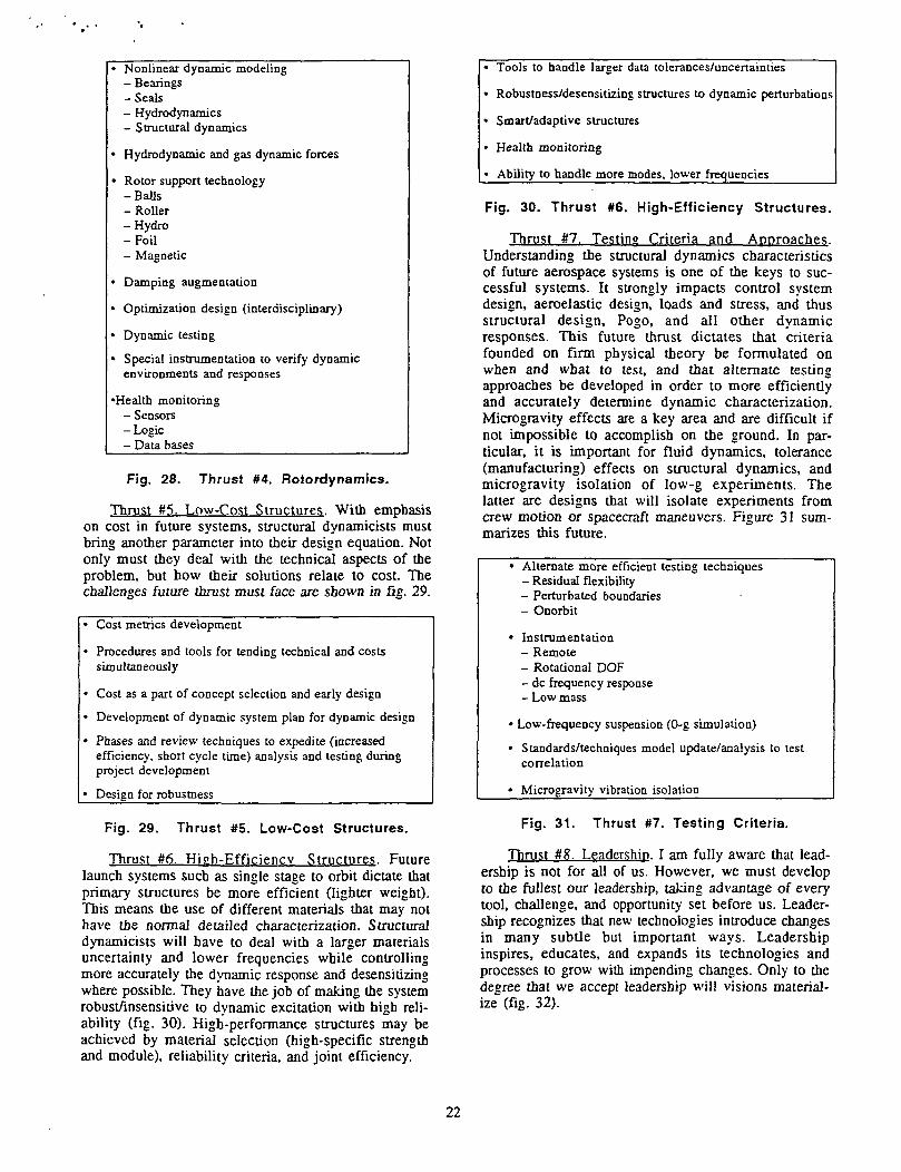
• Nonlinear dynamic modeling- Bearings- Seals- Hydrodynamics- Structural dynamics
• Hydrodynamic and gas dynamic forces
• Rotor support technology-Balls- Roller-Hydro-Foil- Magnetic
> Damping augmentation
• Optimization design (interdisciplinary)
• Dynamic testing
• Special instrumentation to verify dynamicenvironments and responses
•Health monitoring- Sensors- Logic- Data bases
Fig. 28. Thrust #4. Rotordynamics.
Thrust #5. Low-Cost Structures. With emphasison cost in future systems, structural dynamicists mustbring another parameter into their design equation. Notonly must they deal with the technical aspects of theproblem, but how their solutions relate to cost. Thechallenges future thrust must face are shown in fig. 29.
• Cost metrics development
• Procedures and tools for tending technical and costssimultaneously
• Cost as a part of concept selection and early design
• Development of dynamic system plan for dynamic design
• Phases and review techniques to expedite (increasedefficiency, short cycle time) analysis and testing duringproject development
• Design for robustness
Fig. 29. Thrust #5. Low-Cost Structures,
Thrust #6. High-Efficiency Structures. Futurelaunch systems such as single stage to orbit dictate thatprimary structures be more efficient (lighter weight).This means the use of different materials that may nothave the normal detailed characterization. Structuraldynamicists will have to deal with a larger materialsuncertainty and lower frequencies while controllingmore accurately the dynamic response and desensitizingwhere possible. They have the job of making the systemrobust/insensitive to dynamic excitation with high reli-ability (fig. 30). High-performance structures may beachieved by material selection (high-specific strengthand module), reliability criteria, and joint efficiency.
• Tools to handle larger data tolerances/uncertainties
• Robustness/desensitizing structures to dynamic perturbations
• Smart/adaptive structures
• Health monitoring
» Ability to handle more modes, lower frequencies
Fig. 30. Thrust #6. High-Efficiency Structures.
Thrust #7. Testing Criteria and Approaches.Understanding the structural dynamics characteristicsof future aerospace systems is one of the keys to suc-cessful systems. It strongly impacts control systemdesign, aeroelastic design, loads and stress, and thusstructural design, Pogo, and all other dynamicresponses. This future thrust dictates that criteriafounded on firm physical theory be formulated onwhen and what to test, and that alternate testingapproaches be developed in order to more efficientlyand accurately determine dynamic characterization.Microgravity effects are a key area and are difficult ifnot impossible to accomplish on the ground. In par-ticular, it is important for fluid dynamics, tolerance(manufacturing) effects on structural dynamics, andmicrogravity isolation of low-g experiments. Thelatter are designs that will isolate experiments fromcrew motion or spacecraft maneuvers. Figure 31 sum-marizes this future.
• Alternate more efficient testing techniques- Residual flexibility- Perturbated boundaries- Onorbit
• Instrumentation- Remote- Rotational DOF- dc frequency response- Low mass
• Low-frequency suspension (0-g simulation)
• Standards/techniques model update/analysis to testcorrelation
« Microgravity vibration isolation
Fig. 31. Thrust #7. Testing Criteria.
Thrust #8. Leadership. I am fully aware that lead-ership is not for all of us. However, we must developto the fullest our leadership, taking advantage of everytool, challenge, and opportunity set before us. Leader-ship recognizes that new technologies introduce changesin many subtle but important ways. Leadershipinspires, educates, and expands its technologies andprocesses to grow with impending changes. Only to thedegree that we accept leadership will visions material-ize (fig. 32).
22

Vision-based
People-oriented
Communication-focused
Delegation with authority
Fig. 32. Thrust #8. Leadership.
Thrust #9. Enhancement of Human Imagination/Creativity. The only true resource we have to ensurethe future is the human resource of imagination andcreativity. Structural dynamicists have the edge here. Itis mandatory that we continue this thrust individuallyand corporately to enhance this resource. It is the keythat unlocks the future. That is what this meeting isall about.
V. CONCLUSIONS
The thrust areas that have been listed have specialappeal to us who are the specialists, yet they are notthe only challenges before us. Many of the future chal-lenges are paradoxical in form. Although not easy toverbalize, a summary list is attempted in fig. 33.
In summary, knowledge is still the leverage of thefuture. The future is ours to claim and broadcast as weare doing here. I believe that we will catch the visions,focus the thrusts, and claim the future.
Higher performance with robustness
Structural and propulsion system efficiency withhigh performance at lower cost
Dynamic interactive complexity designed usinglimited criteria and standards
Indepth technical expertise selectively applied whilebeing a specialist, a generalise a team player
Structural response control with higher reliability(control implies the introduction of additionalfailure modes)
High performance, high reliability, low cost
Fig. 33. Future Challenges.
REFERENCES
1. Quotes from an uncoverable source.
2. Pye, D.: "The Nature of Design." Reinhold BookCorporation, New York, 1969.
»r
3. Ryan, R.S.: "Problems Experienced and Envi-sioned for Dynamical Physical Systems." NASATP 2508, August 1985.
4. Ryan, R.S.: "Practices in Adequate StructuralDesign." NASA TP 2892, January 1989.
5. Ryan, R.S.: "The Role of Failure/Problems inEngineering: A Commentary on Failures Experi-enced—Lessons Learned." NASA TP 3213, March1992.
6. Ryan, R.S., Mowery, D.K., and Tomlin, D.D.:"The Dynamic Phenomena of a Tethered Satel-lite." NASA TP 3347, May 1993.
7. O'Neal, P.: "The Splendid Anachronisms ofHuntsville." Fortune Magazine, June 1962.
8. Lovingood, J.A.: "A Technique for Including theEffects of Vehicle Parameter Variations in WindResponse Studies." NASA TM X-53042, May1964.
9. Childs, D.W.: "The Space Shuttle Main EngineHigh Pressure Fuel Turbopump RotordynamicInstability Problem." Transactions of theASME, vol. 100, January 1978, pp. 48-57.
10. Junkins, J.L. and Kim, Y.: "Introduction toDynamics and Control of Flexible Structures."AIAA Education Series, AIAA, Inc., WashingtonDC.
11. Greenwood, D.T.: "Classical Dynamics." Pren-tice-Hall, Inc., Englewood Cliffs, NJ, 1977.
12. Meirovitch, L.: "Analytical Methods in Vibra-tions." Macmillan Company, Toronto, Canada,1967.
13. Meirovitch, L.: "Elements of Vibration Analy-sis." Second Edition, McGraw-Hill Book Com-pany, New York, NY, 1986.
14. Meirovitch, L.: "Dynamics and Control of Struc-tures." John Wiley, & Sons, New York, NY,1990.
15. Junkins, J.L. and Turner, J.D.: "Optimal Space-craft Rotational Maneuvers." Studies in Astro-nautics, vol. 3, Elsevier Scientific PublishingCompany, New York, NY, 1985.
16. Craig, R.R. Jr.: "Structural Dynamics—AnIntroduction to Computer Methods." John Wiley& Sons, New York, NY, 1981.
17. Reddy, J.N.: "An Introduction to the Finite Ele-ment Method." McGraw-Hill Book Company,New York, NY, 1984.
18. Meirovitch, L.: "Computational Methods inStructural Dynamics." Sijthoff & Noordhoff,Leyden, The Netherlands, 1980.
23

19. Lee, S. and Junkins, J.L.: "Explicit Generaliza-tions of Lagrange's Equations for Hybrid Coordi-nate Dynamical Systems." Department ofAerospace Engineering, Technical Report AERO91-0301, Texas A&M University, College Sta-tion, TX, March 1991.
20. Meirovitch, L.: "Hybrid State Equations ofMotion for Flexible Bodies in Terms of Quasi-Coordinates." AIAA Journal of Guidance, Con-trol, and Dynamics, vol. 14, No. 5, 1991, pp.1008-1013.
21. Ryan, R.S.: "Structural Design/Margin Assess-ment." NASA TP 3410, September 1993.
24