Embed Size (px)
Citation preview

N A S A NOTE -""NASA ITN 0-8036 e
OAN COPY: -0 1 WL TECHNIC .RY' KIRTLAND A
4. EVALUATION OF A LINEAR WASHOUT FOR SIMULATOR MOTION CUE PRESENTATION DURING LANDING APPROACH 1-
Russell V. Parrish and Dennis J. Martin, Jr. . \ ! ' 1 - 1
Lungley Reseurch Centeir
Humpton, Vu. 23665
3, \ NATIONAL AERONAUTICS A N D SPACE ADMI- WASHINGTON, D. c., \+OCTW 19-75 ,1 s, I
https://ntrs.nasa.gov/search.jsp?R=19750024959 2020-05-07T12:36:37+00:00Z
TECH LIBRARY KAFB. NM
I ~
1. Report No. 2. Government Accession No. 3. Recipient's Catalog No. NASA TN D-8036
4. Title and Subtitle EVALUATION OF A LINEAR WASHOUT FOR SIMULATOR MOTION CUE PRESENTATION DURING LANDING APPROACH
7. Author(s)
Russel l V. P a r r i s h and Dennis J. Martin, Jr.
9. Performing Organization Name and Address
NASA Langley Research Center
Hampton, Va. 23665
12. Sponsoring Agency Name and Address
National Aeronautics and Space Administration Washington, D.C. 20546
15. Supplementary Notes
I 5. Report Date October 1975
I 6. Performing Organization Code
8. Performing Organization Report No.
L -9984 10. Work Unit No.
504-09-41-01
I 11. Contract or Grant No,
I ] 13. Type of Report and Period CoveredI Technical Note
14. Sponsoring Agency Code
I
I
I Dennis J. Martin, Jr., is an employee of Electronic Associates , Inc., Hampton, Va.
16. Abstract
The comparison of a fixed-base versus a five-degree-of-freedom motion base s imulation (the heave cue was not presented) of a 737 conventional take-off and landing (CTOL) a i rc raf t performing instrument landing system (ILS) landing approaches has been used to evaluate a l inear motion washout technique. The fact that the pilots felt that the addition of motion increased the pilot workload and this increase was not reflected in the objective data resu l t s , indicates that motion cues, as presented, are not a contributing factor to root-meansquare ( rms) performance during the landing approach task. Subjective resu l t s f rom standa r d maneuvering about straight-and-level flight for specific motion cue evaluation revealed that the longitudinal channels (pitch and surge) and possibly the yaw channel produce acceptable motions. The ro l l cue representat ion, involving both ro l l and sway channels, was found to be inadequate for la rge rol l inputs, as used for example, in turn en t r ies .
-17. Key-Words (Suggested by Author(s1 ) 18. Distribution Statement
Landing approach Unclassified - Unlimited Washout sys tem Coordinated washout
Subject Category 05 .-
119. Security Classif. (of this report) 20. Security Classif. (of this page) 1 21. ~0.~ ; Pages I 22. Price'
Unclassified . .
Unclassified $4.25
For sale b y the National Technical Information Service, Springfield, Virginia 22161
I
--
EVALUATION OF A LINEAR WASHOUT
FOR SIMULATOR MOTION CUE PRESENTATION
DURING LANDING APPROACH
Russell V. Pa r r i sh and Dennis J. Martin, Jr.* Langley Research Center
SUMMARY
The comparison of a fixed-base versus a five-degree-of -freedom motion base simuulation (the heave cue was not presented) of a 737 conventional take-off and landing (CTOL) aircraf t performing instrument landing system (ILS) landing approaches has been used to evaluate a linear motion washout technique. The fact that the pilots felt that the addition of motion increased the pilot workload and this increase was not reflected in the objective data resul ts , indicates that motion cues, as presented, are not a contributing factor to root -mean-square ( rms) performance during the landing approach task. Subjective resul ts from standard maneuvering about straight-and-level flight for specific motion cue evaluation revealed that the longitudinal channels (pitch and surge) and possibly the yaw channel produce acceptable motions. The roll cue representation, involving both roll and sway channels, was found to be inadequate for large roll inputs, as used for example, in turn entries.
INTRODUCTION
The major factor affecting the quality of a motion simulation in comparison with a fixed-base simulation of an aircraf t , aside from the physical characterist ics of the hardware, is the washout scheme. The washout scheme is used to constrain the motion drives to be within the physical capabilities of the motion base and still maintain the fidelity of the motion cues provided to the simulator pilot.
The comparisun of a fixed-base versus a five-degree-of -freedom motion base simulation of a 737 CTOL aircraf t during landing approach has been used to evaluate a l inear motion washout technique. The motion software utilized in the study is described in reference 1 and the hardware (the motion base) in references 2 and 3. The linear washout scheme w a s the Langley adapted version of Schmidt and Conrad's linear coordinated washout circuitry (refs. 4 and 5). The evaluation process consisted of the collection of objective
*Electronic Associates, Inc. , Hampton, Va.
1111-1-111 I I I I II 111111111I1I.IIIIII~III I I IIIIII.I~11111111 I111111II 11111

and subjective data from 90 simulated landing approaches, as well as subjective data from standard maneuvering about straight -and-level flight for specific motion cue evaluation.
The landing approach task was selected for the collection of the objective data, despite the suggestion in reference 4 that the task might be a poor one for motion evaluation, for several reasons:
(1)Objective performance measures a r e readily available
(2) Landing approach simulation with motion is widespread in use
(3) Statistical data could provide verification of the previous suggestion of reference 4
SYMBOLS
Values a r e given in both SI and U.S. Customary Units. The measurements and calculations were made in U.S. Customary Units.
main effects in analysis of variance
two factor interactions in analysis of variance
three factor interaction in analysis of variance
acceleration lead parameters for translational channel lag compensation, sec2
damping parameters for second-order translational washout f i l ters , rad/sec
velocity lead parameters for translational channel lag compensation, sec
frequency parameters for second-order translational washout f i l ters , rad/se c2
translational acceleration braking parameters , sec-’
mean aerodynamic chord, m (ft)
scale factor, deg/rad

I
fE ,X'fCC ,y
fc,z
fi,x,fi ,y ,fi,z
f!' 192
f S , X ' S , Yf
fs,z
f, ,fy,fz
f Z ) C
G1
g
h
hC
h0
KO
body -axis longitudinal and lateral accelerations a t centroid location after low -pass filtering, m/sec2 (ft/sec2)
body-axis vertical acceleration (referenced about lg ) at centroid location after high -pass filtering, m/sec2 (ft/sec2)
inertial axis translational acceleration commands pr ior to translational washout, m/sec2 (ft/sec2)
inertial axis specific force e r r o r signals, m/sec2 (ft/sec2)
components in inertial axis of filtered body-axis vertical acceleration centroid location, m/sec2 (ft/sec2)
artificial yaw e r r o r signal, m/sec2 (ft/sec2)
body -axis longitudinal and lateral accelerations a t centroid location, m/sec2 (ft/sec2) o r g units; Fsx and Fsy in the computer plots
body -axis vertical acceleration (referenced about lg) a t centroid location, m/sec2 (ft/sec2) or g units; Fsz in the computer plots
aircraft-body -axis translational accelerations) m/sec2 (ft/sec2)
body -axis translational acceleration at centroid location, m/sec2 (ft/sec 2)
glide-slope e r r o r gain
acceleration due to gravity, l g = 9.8 m/sec2 (32.2 ft/sec2)
altitude, m (ft)
commanded altitude, m (ft)
height of aircraft c.g. at touchdown, m '(ft)
heading e r r o r gain
3
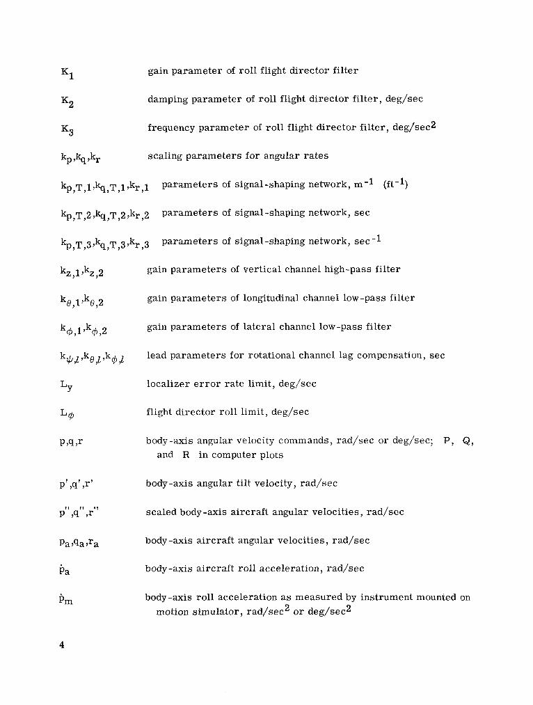
K1 gain parameter of roll flight director fi l ter
K2 damping parameter of rol l flight director filter, deg/sec
K3 frequency parameter of rol l flight director filter , deg/sec2
kp 9% ,kr scaling parameters for angular ra tes
kp ,T ,13% ,T,1,kr,1 parameters of signal-shaping network, m - l ( f t - l )
kp,T,2 , Q , T , ~,k,,2 parameters of signal-shaping network, s ec
kp ,T ,3 ,~ ,T ,3 ,k r ,3 parameters of signal-shaping network, sec-1
gain parameters of vertical channel high-pass fi l ter
gain parameters of longitudinal channel low -pass fi l ter
gain parameters of lateral channel low -pass fi l ter
lead parameters for rotational channel lag compensation, sec
localizer e r r o r ra te limit, deg/sec
flight director roll limit, deg/sec
body -axis angular velocity commands, rad/sec or deg/sec; P, Q, and R in computer plots
body-axis angular tilt velocity, rad/sec
scaled body-axis a i rcraf t angular velocities , rad/sec
body-axis a i rcraf t angular velocities , rad/sec
body-axis a i rcraf t roll acceleration, rad/sec
body-axis roll acceleration as measured by instrument mounted on motion simulator, rad/sec2 or deg/sec2
4
R range from runway, m (ft)
R p R y P Z centroid location with respect to c .g., m (ft)
s1 pitch input to pitch flight director, deg
s2 output of first order pitch flight director, deg
S Laplace operator
t t ime, sec
t0 start ing t ime for roll flight director operation
VP velocity limit, m/sec (ft/sec)
"2 Earth-axis longitudinal coordinate of a i rcraf t c.g. , m (ft)
X,Y )Z commanded inertial translational position of motion simulator, m (ft)
1 1 -
X,Y 7 2 commanded translational positions after compensation, m (ft)
xLF ,yLF)ZLF scale factors on position l imits
.. .. .. xb 'Yb ''b intermediate inertial axis translational acceleration commands,
m/sec2 (ft/sec2)
Xd'Yd 7'd inertial-axis translational position commands, m (ft)
7yz 'zz inertial-axis position l imits for translational channels, m (ft)
xz,yz,zz inertial-axis acceleration l imits for translational channels) m/sec2 (ft/secz>
XO longitudinal coordinate of runway touchdown point, m (f t )
Xp,Yp,Zp coordinates of pilot's station with respect to c.g. in body-axis system, m (ft)
5
xp,c,yp,c,zp,c coordinates of centroid location with respect to pilot's station in the body-axis system, m (ft)
xr x-distance of a i rc raf t c.g. from runway, m '(ft)
Y l Earth-axis lateral coordinate of a i rcraf t c.g., m (ft)
yb distance behind runway touchdown point of localizer beam origin, m (ft)
YO lateral coordinate of runway touchdown point, m (ft)
Y r y-distance of a i rcraf t c.g. from runway, m (ft)
Zneut actuator extension for selected neutral point, m (ft)
YC commanded glide -slope angle, deg
At time s tep s ize , sec
'a aileron deflection angle, rad
'h vertical glide -slope e r r o r , m (ft)
E Y
localizer e r r o r , deg
E YZ localizer e r r o r lag, deg
E Y ,Q
ra te limited localizer e r r o r , deg
EY glide -slope e r r o r , deg
E + heading e r r o r , deg
Ew scaled heading e r r o r , deg
ea actual a i rcraf t pitch angle, deg
OC commanded pitch angle, deg
QS pitch command signal, deg
6
damping parameter for vertical channel high-pass filter
damping parameters fo r longitudinal and lateral channel low -pass filters
actual a i rcraf t rol l angle, deg
commanded rol l angle, deg
roll flight director filter input, deg
intermediate rol l command angle deg
roll command signal, deg
variables of rol l flight director filter, deg
commanded inertial angular position of motion simulator, rad
commanded angular positions after compensation, rad
actual a i rcraf t heading, deg
commanded heading, deg
commanded inertial tilt ra tes , rad/sec
frequency parameter of vertical channel high-pass filter, rad/sec
frequency parameter of longitudinal and lateral channel low -pass filters, rad/sec
A dot over a variable indicates the t ime derivative of the variable.
WASHOTJT CIRCUITRY
The adapted version of Schmidt and Conrad's l inear coordinated washout circuitry used in this study is shown in figure 1 in block diagram form. The detailed equations are presented in appendix A. The function of the circuitry is to represent the translational accelerations and the rotational rates of the simulated aircraf t while constraining the motion commands to be within the hardware capabilities. The concept of this coordinated
7
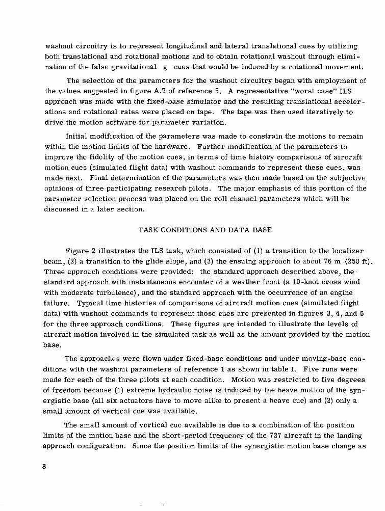
washout circuitry is to represent longitudinal and lateral translational cues by utilizing both translational and rotational motions and to obtain rotational washout through elimination of the false gravitational g cues that would be induced by a rotational movement.
The selection of the parameters for the washout circuitry began with employment of the values suggested in figure A.7 of reference 5. A representative "worst case" ILS approach was made with the fixed-base simulator and the resulting translational accelerations and rotational r a t e s were placed on tape. The tape was then used iteratively to drive the motion software for parameter variation.
Initial modification of the parameters was made to constrain the motions to remain within the motion l imits of the hardware. Further modification of the parameters to improve the fidelity of the motion cues, in t e rms of t ime history comparisons of a i rcraf t motion cues (simulated flight data) with washout commands to represent these cues, was made next. Final determination of the parameters was then made based on the subjective opinions of three participating research pilots. The major emphasis of this portion of the parameter selection process was placed on the roll channel parameters which will be discussed in a later section.
TASK CONDITIONS AND DATA BASE
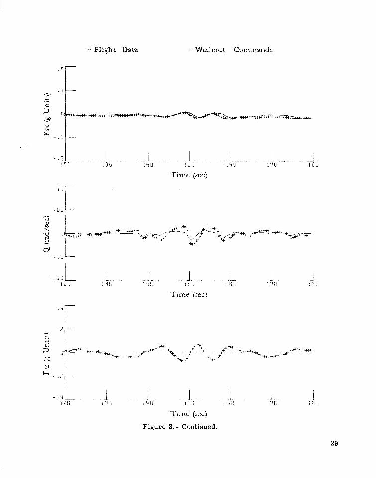
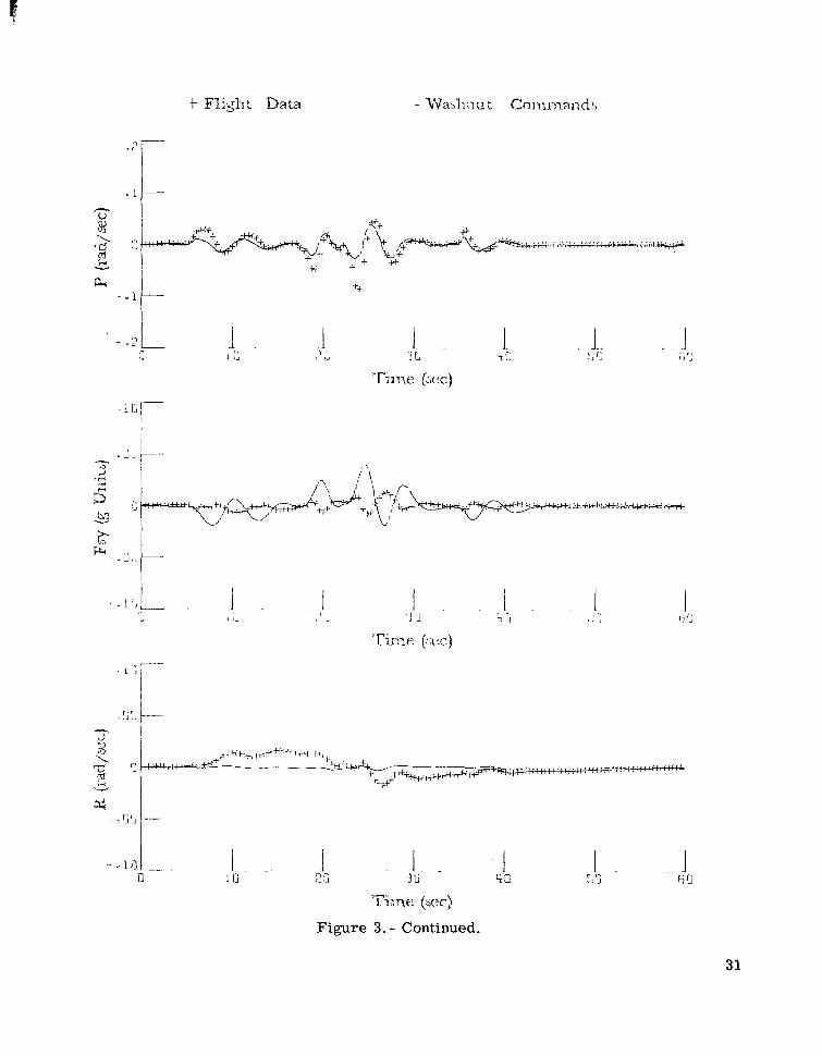
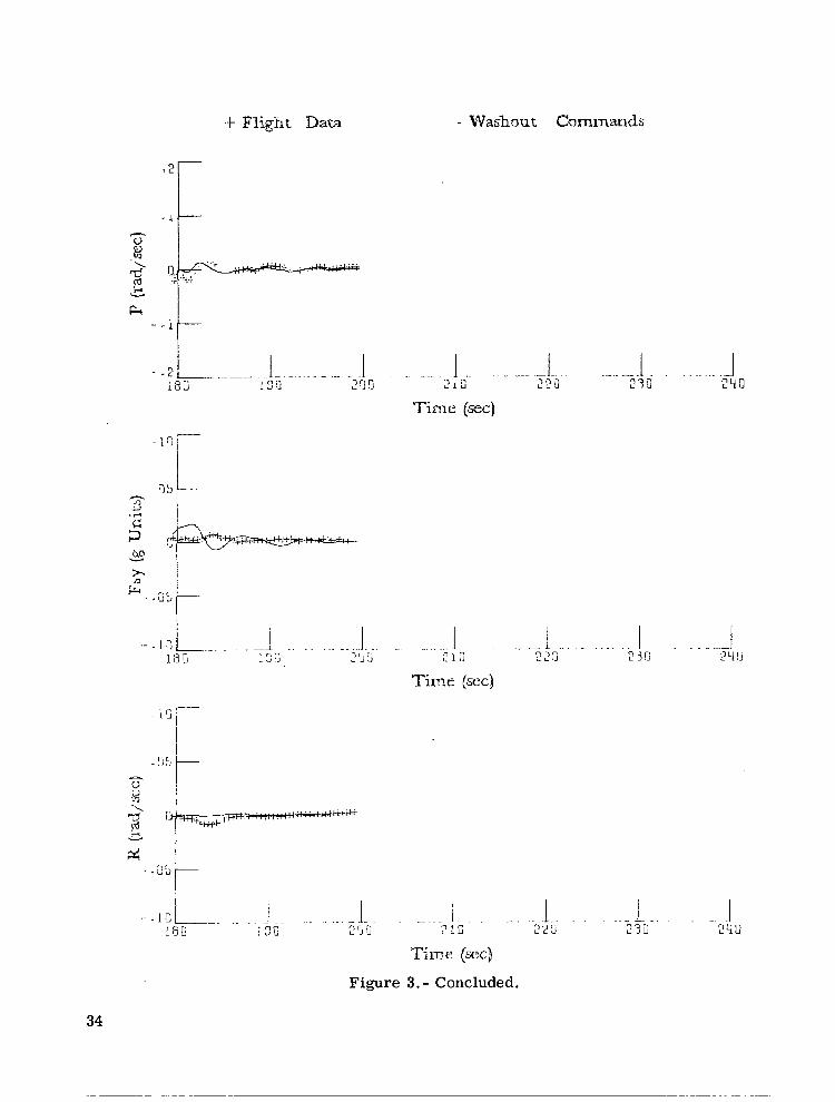
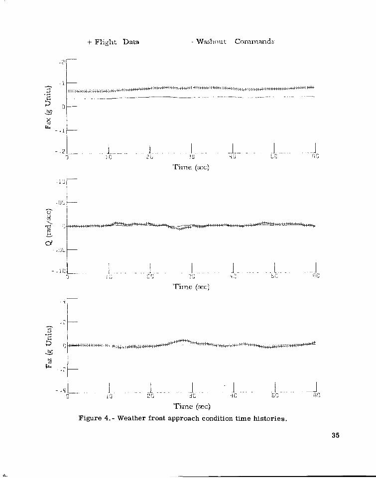
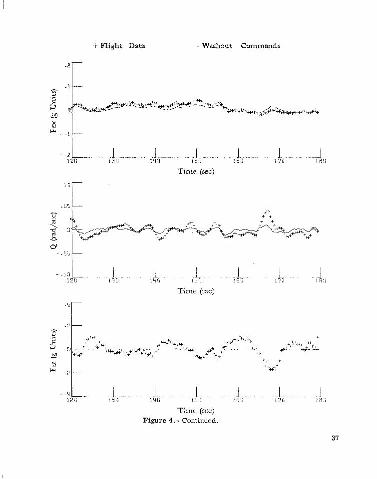
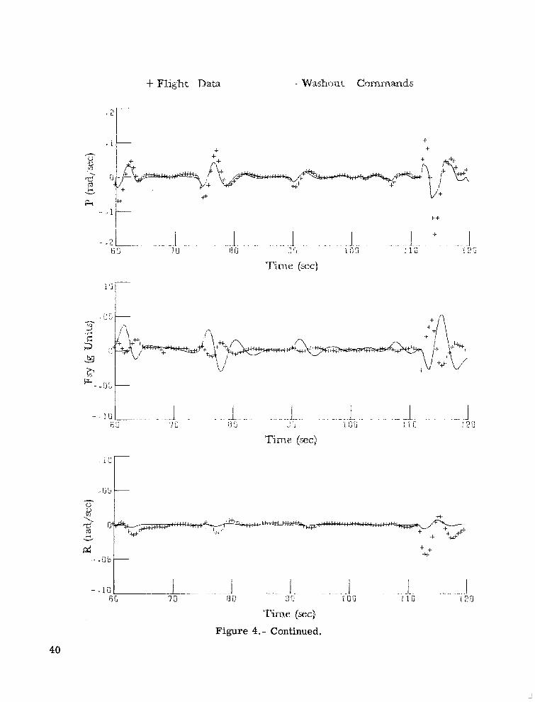
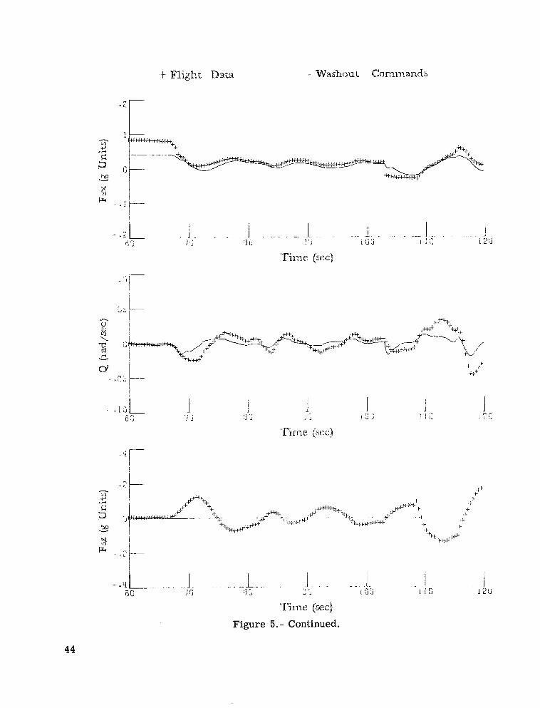
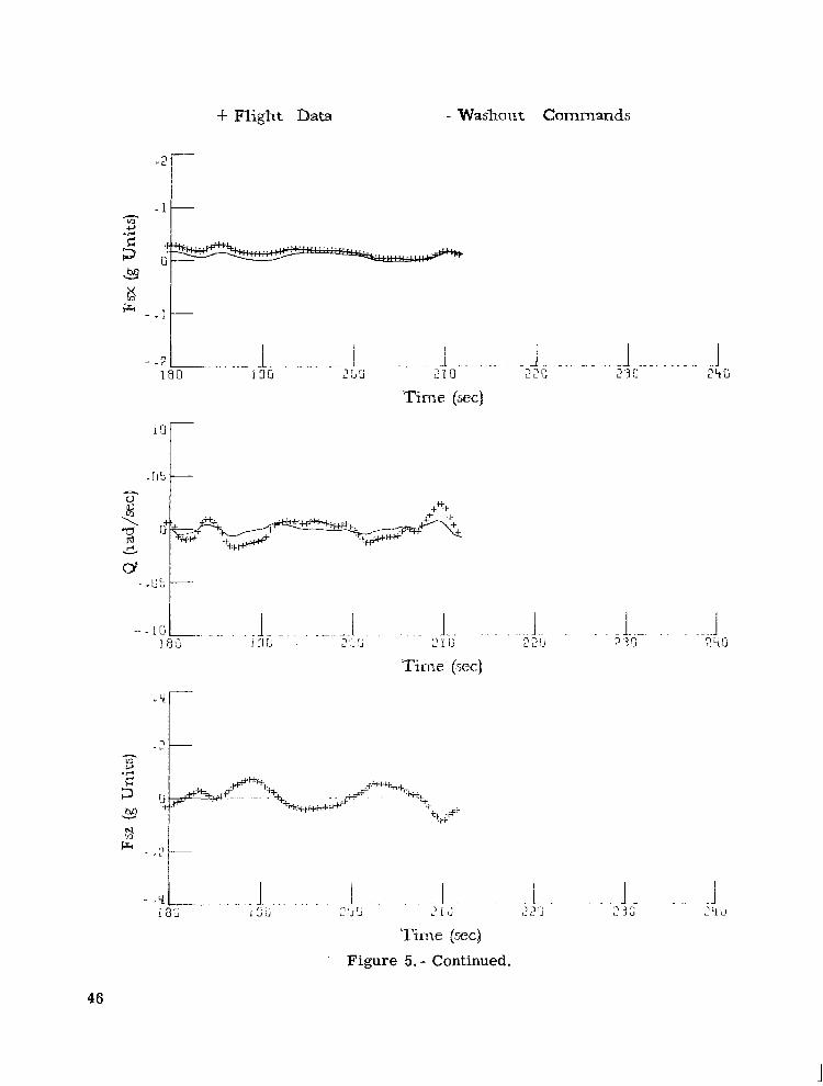
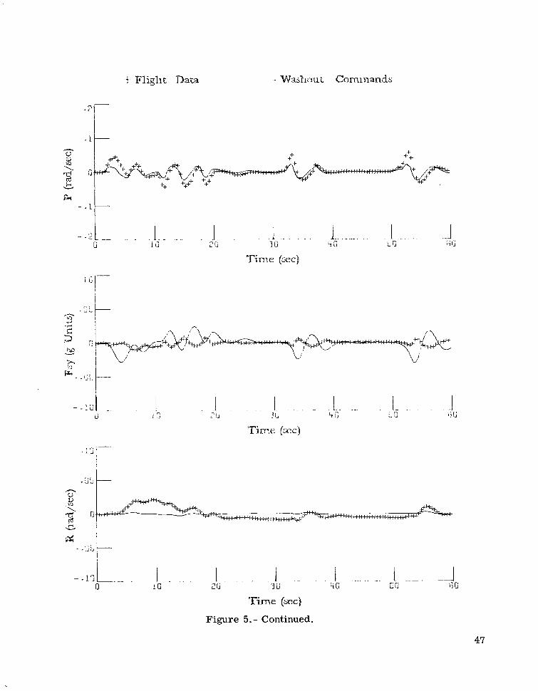
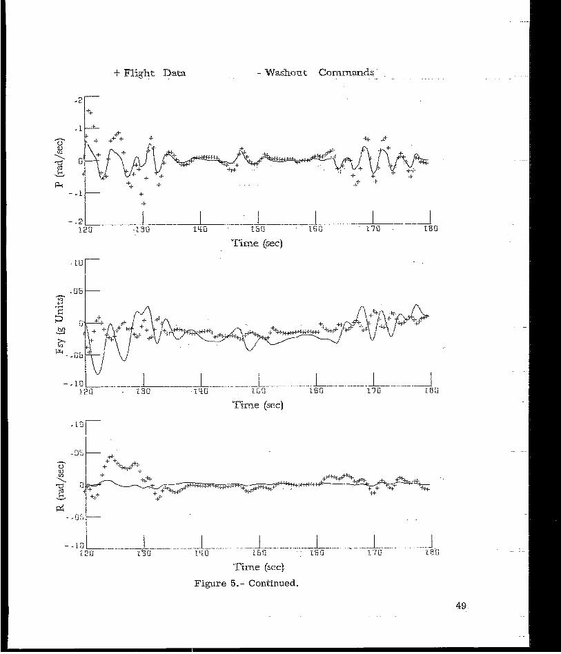
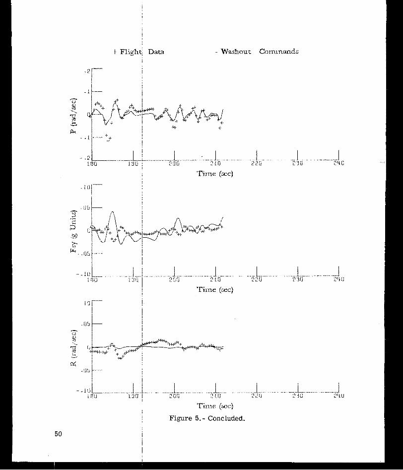
Figure 2 i l lustrates the ILS task, which consisted of (1) a transition to the localizer beam, (2) a transition to the glide slope, and (3) the ensuing approach to about 76 m (250 ft) . Three approach conditions were provided: the standard approach described above, the standard approach with instantaneous encounter of a weather front (a 10-knot c ross wind with moderate turbulence), and the standard approach with the occurrence of an engine failure. Typical t ime histories of comparisons of a i rcraf t motion cues (simulated flight data) with washout commands to represent those cues are presented in figures 3, 4 , and 5 for the three approach conditions. These figures are intended to illustrate the levels of aircraft motion involved in the simulated task as well as the amount provided by the motion base.
The approaches were flown under fixed-base conditions and under moving-base conditions with the washout parameters of reference 1 as shown in table I. Five runs were made for each of the three pilots at each condition. Motion was restr ic ted to five degrees of freedom because (1)extreme hydraulic noise is induced by the heave motion of the synergistic base (all s ix actuators have to move alike to present a heave cue) and (2) only a small amount of vertical cue was available.
The small amount of vertical cue available is due to a combination of the position l imits of the motion base and the short-period frequency of the 737 aircraft in the landing approach configuration. Since the position l imits of the synergistic motion base change as
the orientation of the base var ies , the position l imits used in determining the linear washout parameters must be conservative. For the motions involved in this study, the ver t i cal position l imits were chosen to be 0.45 m (1.5 ft) . The low-frequency content of the normal acceleration of the aircraf t ( less than 1 rad/sec, neglecting turbulence) is due to the low short-period frequency. (See table II.) The amount of vertical cue available for motion simulation is thus less than 0.05g (the product of amplitude and frequency squared). The participating pilots felt that the vertical cue available was not worth the noise distraction.
During the performance of the landing approach task under the preceding conditions, root-mean-square ( rms) data were collected over two regimes. A short-duration regime, intended to ref lect the immediate effect of the weather front and the engine-failure conditions, and a long-duration regime, to evaluate total performance, were used. The r m s values were obtained for deviations of the glide slope, localizer, pitch command ba r , roll command ba r , and speed command ba r . The equations for the flight director used in this study are presented in appendix B.
Subjective data consisted of revised Cooper-Harper ratings of the ILS task as shown in table III (ref. 6) and pilot comments solicited during objective data collection. In addition, standard maneuvers about straight-and-level flight were also used to generate sub jective pilot evaluation data of the motion cues.
OBJECTIVE DATA RESULTS
The design of the experiment for objective data consisted of the 2 x 3 x 3 factorial design (ref. 7). The fixed-effect factors a r e pilots, approach conditions, and motion ver sus fixed-base operation. The resul ts of the analysis of variance for each of the 10 separate r m s measurements (deviations of glide slope, localizer, pitch command b a r , roll command ba r , and speed command ba r for short and long durations) a r e shown in table IV. Significance of the one-tailed F-tests is indicated by an aster isk for the 5-percent level and a double as te r i sk for the l -percent level.
The resul ts indicate significant statist ical differences in mean performances between pilots and also between approaches. No significant differences in mean performances are found between motion and fixed-base operation. The occasional statist ical significance of the two factor interaction AC indicates that the differences between pilots varied with the approach condition over all motion conditions, o r alternately, the differences in perfor mance between approaches varied from pilot to pilot, regardless of the motion condition, for some of the performance measures.
9

SUBJECTIVE DATA RESULTS
Although the subjective data obtained from the pilots ranged the gamut from complete dislike of the motion used to something approaching delight, two points of agreement were shared by all three pilots: (1) the addition of motion increased the pilot workload (the pilots believed their ability to make the precision inputs required to null the flight director ccmmand ba r s was lessened under motion conditions) and (2) the rol l motion is borderline, if not unacceptable, f o r large ro l l inputs. While the first point of agreement is not borne out by the objective data resul ts , the revised Cooper-Harper ratings presented in table V clearly i l lustrate this belief (increased pilot workload is reflected in an increased Cooper-Harper rating), and possibly suggest that the selected ILS task is a poor one for motion evaluation in t e rms of objective data (substantiating the opinion expressed in ref. 4).
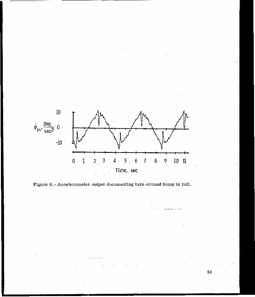
The second point of agreement, the poor representation of rol l , can be substantiated with objective data. The problem is a combination of hardware weakness and software performance. The hardware weakness, a turn-around bump (a problem common to most motion systems), exists in all degrees of freedom, but was only noticed by the pilots in the rol l channel, perhaps due to the frequency and amplitude of the rol l inputs. This problem is documented in figure 6 with a time history taken from an accelerometer mounted on the motion-base cockpit to measure pm. The base was driven with a sine wave of 4' amplitude and at a frequency of 1 . 5 rad/sec.
The software performance problem is a result of the difficulty in presenting a roll cue on a motion base, as discussed in reference 8. A negative rol l angle induces a positive sway force fs,y in a motion simulator, due to the gravity vector. As may be seen from the flight data of figures 3 , 4 , and 5 , fS ty and p a r e in phase, and thus t ranslational acceleration is necessary to (1)offset the misalinement of the gravity vector due to the roll cue and (2) present the side-force cue.
The parameters for the coordinated roll channel, as picked by the pilots involved, yield the results presented in figure 7 for a pulse input on the aileron. The fact that the negative peak of p is larger than the positive peak could give the pilot the impression that the net result of the maneuver was a left bank, ra ther than a right bank.
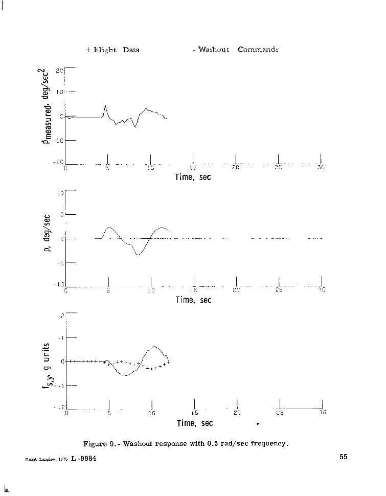
The parameters of the rol l channel used in the study have an effective natural f r e quency of about 0 . 1 rad/sec. Figures 8 and 9 display the washout response for the pulse input of figure 7 for effective natural frequencies of 0.3 and 0 . 5 rad/sec, respectively. This range of frequency is typically employed in classical circuits (ref. 5) . Subjectively, the pilots preferred the frequency of 0.1 rad/sec. All frequencies tr ied gave the impression of a left bank, ra ther than a right bank, to two of the three pilots. This impression
10
was obtained only for large ro l l inputs, such as used in turn entr ies , and the false bank was not noted during the control inputs required for the ILS task.
The lack of sufficient lateral t ravel for sway representation was not noticed subjectively by any of the participating pilots, even though fs,y is 180° out of phase for the chosen parameter values. Parameters that bring fs,y in phase resul t in p representation being 180° out of phase, a situation considered by the pilots to be intolerable.
Table VI presents the subjective ratings of the three pilots of the motion cues encountered during maneuvering about straight-and-level flight. Pilot 1has had the only experience to date in the flight version of the simulated aircraft, and his general comments were that the motion felt like a long, narrow airplane that wallows, although large rol l inputs felt "mechanical" (artificial). He felt that the yaw cue was the best of any motion simulator he had flown. Pilot 2 has had little experience in long-bodied airplanes and felt that generally the motions were jerky and confusing. Pilot 3 felt that the motions were unnatural and distracting, ra ther than helpful, and did not feel like an airplane. However , he would rather fly with motion because the confusion increases the workload level.
CONCLUDING REMARKS
The objective and subjective resul ts of this study lead to two general conclusions, one of which is concerned with the ILS task and the other with the question of motion validation of the linear washout. The fact that the pilots all felt that the addition of motion increased the workload, and yet this increase in workload did not deteriorate the pilot per formance of the task, indicates that motion cues, as presented, a r e not important in t e rms of r m s performance measures during instrument landing system landing approaches.
The question of motion evaluation can best be discussed in t e rms of the subjective ratings of the individual cues. The roll representation must be improved by changes in either the software, the hardware, o r both. The yaw cue may or may not be acceptable, with the issue of pilot experience in long-bodied aircraf t intruding on the evaluation. The same factor could be in force on the evaluation of the pitch cue. The motion cues with throttle change w e r e acceptable.
Langley Research Center National Aeronautics and Space Administration Hampton, Va. 23665 July 11, 1975
11

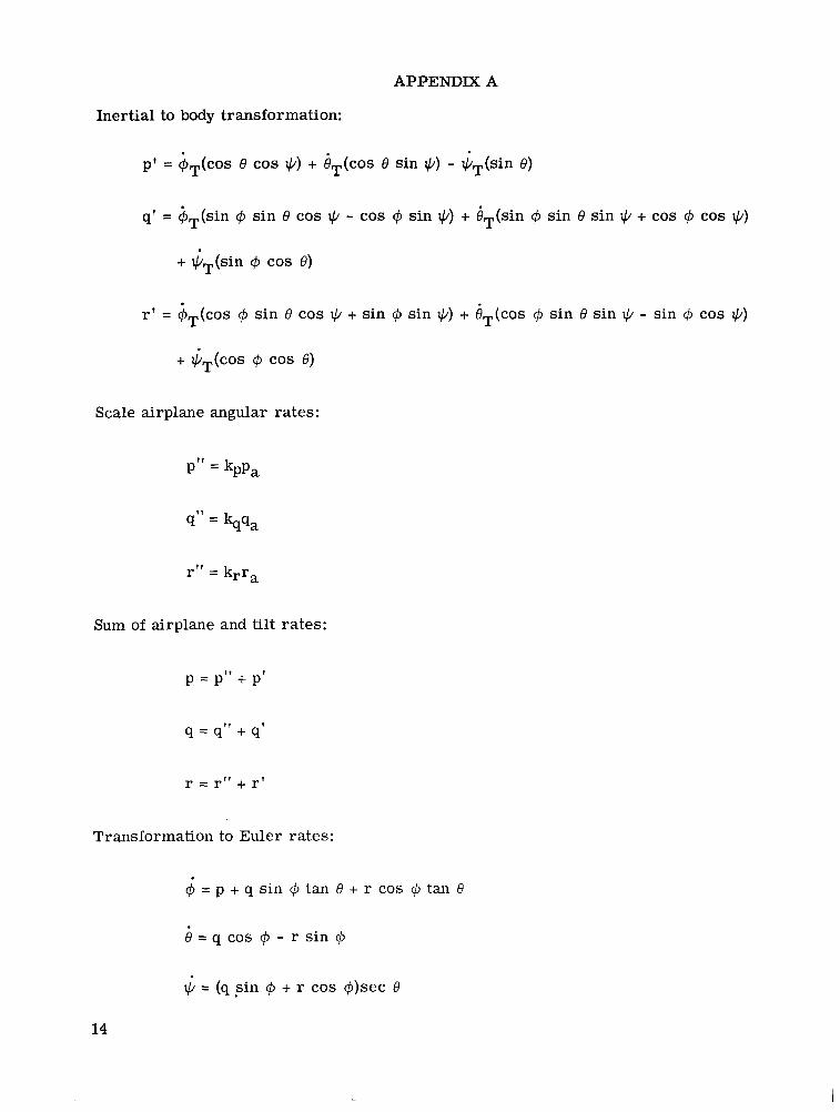
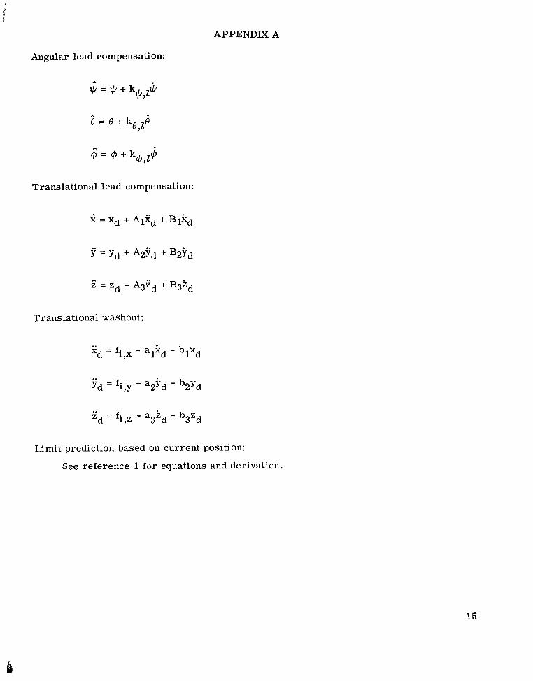
APPENDIX A
DETAILED EQUATIONS FOR THE WASHOUT CIRCUIT
The following is a block-by-block l is t of equations corresponding to figure 1:
Centroid transformation:
Variation about lg:
f S , Z = f Z , C + g
High-pass filter:
Low-pass filter:
12

APPENDIX A
Body to inertial transformation, high-frequency components:
f!1,x = fc,z(cos @ sin e cos + + sin @ s in +)
f!1 ,Y = fC,,(cos @ sin e sin + - sin @ cos q)
f! = fc,z(cos @ COS e)1 9 2
Body to inertial transformation, low-frequency components:
fr,x = f* (cos e cos +) + f* (sin @ sin e cos + - cos @ sin +)c,x C7Y
- g(cos @ sin e cos + + sin @ sin +)
1 , Y c,x(cos e s in $1 + f*f* = f* C,Y
(sin cp sin e sin + + cos @ cos +)
- g(cos @ sin e s in + - sin
Sum of low- and high-frequency components:
fi ,x = f.'1,x + f*l,x
fi,y = f!1 , Y
+ f*1,Y
fi,z = f l 1,=
Signal -shaping network:
$J cos +)
'T = kq,T, lkq,T,2f*i,x + kq,T,1 1f*i,x dt + kq,T,1kq,T,3 ss fT,x dt dt
$T = -kp,T,1kp,T,2fT,y - kp,T,l dt - kp,T,lkp,T,3 11fT,y dt dt
13
I
APPENDIX A
Inertial to body transformation:
pt = 4T(cos e cos IC/)+ COS e sin *) - GT(sin e )
q1 = $T(sin @ sin e cos rc/ - cos ~3 sin +) + BT(sin @ s in e s in + + cos 4 cos
+ *,(sin @ cos e)
rl = $T(co~4 sin e cos IC/ + sin @ sin IC/)+ iT(cos @ sin e sin IC/ - sin @ cos +)
+ $+os @ cos e )
Scale airplane angular rates:
P" = kpPa
q" =
rrr= krra
Sum of airplane and tilt rates:
p = p" + p1
q = q" + q'
r = 1''' + r '
Transformation to Euler rates:
@ = p + q sin @ tan 8 + r cos @ tan 8
e = q cos @ - r sin @
IC/ = (q s i n @ + r cos @)sec8
14
APPENDIX A
Angular lead compensation:
j = + + k +J $
2 = 8 + k 6871
$ = @ + kcp J 4
Translational lead compensation:
2, = fi7x - alkd - blxd
2, = fi,z - askd - b3zd
Limit prediction based on current position:
See reference 1 for equations and derivation.
15

APPENDIX B
FLIGHT DIRECTOR EQUATIONS
The following is a list of the equations for the flight director used in this study:
Input equations:
xy = (xZ - xo) COS q c + (YZ - YO) sin +c/c
R = (x; +
h, = R tan yc + ho
E = f tan -1 'h-Y R
e - f tan-' yrY - R+y
Pitch flight director :
0.14 (h-50) (h < 100) = {h/15 (h 2 100)
GI limited to LO, 1001
s1 = -(ea + 2)
. s1 -s2s2 =
15 (Initial condition: S2 = S1)
ec = ~~e~ - s2
Bc limited to k12, 121
es = 0, + s1
16

APPENDIX B
Roll flight director:
� Y C =
E Y - E Y,Q (Initial condition: = 0)At
E Y,Z limited to
�l$)l = KO�+
@f = - 65eY,p + 1.6l$a
($1= KIGf - K2$l - K3@1 (Initial conditions: $1 = 0 and @1 = 8.499@
@i = 21.26 Y,P + El$ - $1
Gi limited to [-30, 301
@c = @ . - El$1
qC limited to
Ly = 0.4
L@= 25
KO= 2.8
K1 = 2.833
K2 = 2.867
K3 = 0.3333
Ly = 0.12
L@= 1 5
KO = 3.8
K1 = 3.5714
K2 = 3.534
K3 = 0.7518
17

REFERENCES
1. Pa r r i sh , Russell V.; Dieudonne, J ames E.; and Martin, Dennis J . , Jr.: Motion Software for a Synergistic Six-Degree-of -Freedom Motion Base. NASA TN D-7350, 1973.
2. Dieudonne, J ames E.; Pa r r i sh , Russell V.; and Bardusch, Richard E.: An Actuator Extension Transformation for a Motion Simulator and an Inverse Transformation Applying Newton-Raphson’s Method. NASA TN D-7067, 1972.
3. Pa r r i sh , Russell V.; Dieudonne, J ames E.; Martin, Dennis J., Jr.; and Copeland, J ames L.: Compensation Based on Linearized Analysis for a Six-Degree -of -Freedom Motion Simulator. NASA TN D-7349, 1973.
4. Schmidt, Stanley F.; and Conrad, Bjorn: Motion Drive Signals for Piloted Flight Simulators. NASA CR-1601, 1970.
5. Schmidt, Stanley F.; and Conrad, Bjorn: A Study of Techniques for Calculating Motion Drive Signals for Flight Simulators. Rep. No. 71-28, Analytical Mechanics Associates, Inc., July 1971. (Available as NASA CR-114345.)
6. Harper, Robert P., Jr.; and Cooper, George E.: A Revised Pilot Rating Scale for the Evaluation of Handling Qualities. Stability and Control, Pt. I, AGARD CP No. 17, Sept. 1966, pp. 227-245.
7. Steel, Robert G. D.; and Torr ie , J ames H.: Principles and Procedures of Statistics. McGraw-Hill Book Co., Inc., 1960.
8. Pa r r i sh , Russell V.; Dieudonne, James E.; Martin, Dennis J.; and Bowles, Roland L.: Coordinated Adaptive Filters for Motion Simulators. Proceedings of the 1973 Summer Computer Simulation Conference, Simulation Councils, Inc., c .1973, pp. 295-300.
18
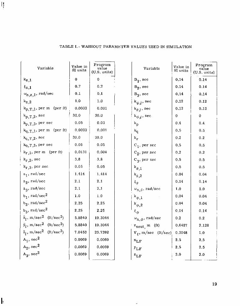
TABLE 1.- WASHOUT PARAMETER VALUES USED IN SIMULATION
Value in Progr an Variable value Variable Value in
SI units (u.S. unit SI units ~ ~~
0 0 B1, s e c 0.14
0.7 0.7 B2, s e c 0.14
0.1 0.1 B3, sec 0.14
1.o 1.o k q / p sec 0.12
0.0033 0.001 kg , l , s e c 0.12
30.0 30.0 k@J, s e c 0
0.05 0.05 kp 0.4
0.0033 0.001 ks 0.5
30.0 30.0 k r 0.2
0.05 0.05 C1, per s e c 0.5
0.0131 0.004 C2, per s e c 0.2
3.8 3.8 C3, per s ec 0.5
0.05 0.05 k 871 0.5
1.414 1.414 k8,2 0.04
2.1 2.1 58 0.14
2.1 2 .1 w n , e , r ad /sec 1.o 1.o 1.o
k@,l 0.04
2.25 2.25 k @ 92 0.04
2.25 2.25 <@ 0.14
5.8840 19.3044 wn,@, rad /sec 0.2
5.8840 19.3044 Zneut, m (ft) 0.6487
7.8453 25.7392 V,, m/sec (ft/sec 0.3048
0.0069 0.0069 X~~ 2.5
0.0069 0.0069 YLF 2.5
0.0069 0.0069 3.0Z~~
~
Programvalue
(US . units)
0.14
0.14
0.14
0.12
0.12
0
0.4
0.5
0.2
0.5
0.2
0.5
0.5
0.04
0.14
1.o 0.04
0.04
0.14
0.2
2.128
1.o 2.5
2.5
3 .O
19

TABLE 11.- 737 FLTGHT CHARACTERISTICS
Weight. N (lb) . . . . . . . . . . . . . . . . . . 400 341
Center of gravity . . . . . . . . . . . . . . . . . . . . . . . Flap deflection. deg . . . . . . . . . . . . . . . . . . . . . Landing gear . . . . . . . . . . . . . . . . . . . . . . . . . Damping rat io for -
Short period . . . . . . . . . . . . . . . . . . . . . . . . Long period . . . . . . . . . . . . . . . . . . . . . . . . Dutch roll . . . . . . . . . . . . . . . . . . . . . . . . .
Period. sec. for -Short period . . . . . . . . . . . . . . . . . . . . . . . . Long period . . . . . . . . . . . . . . . . . . . . . . . . Dutch rol l . . . . . . . . . . . . . . . . . . . . . . . . .
20
(90 000)
0.31c
40
Down
0.562 0.089 0.039
6.30 44.3 5.12
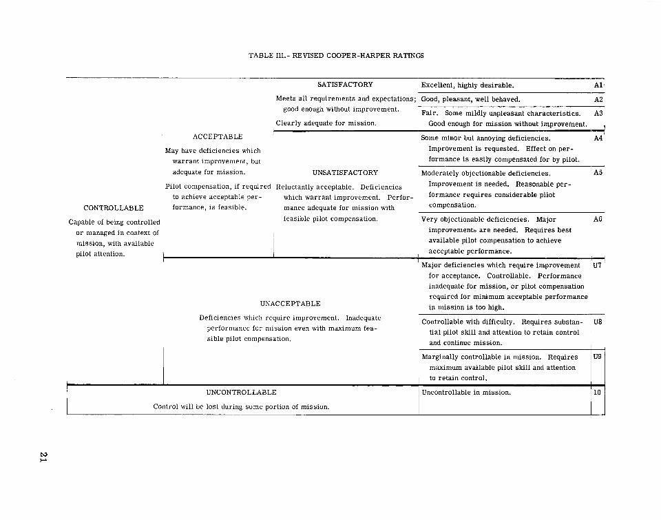
TABLE 111.- REVISED COOPER-HARPER RATINGS
SATISFACTORY Excellent, highly desirable. A1-Meets all requirements and expectations; Good, pleasant, well behaved. A2
good enough without improvement. Fair. Some mildly unpleasant characterist ics. A3 Clearly adequate for mission. Good enough for mission without improvement.
t +' ACCEPTABLE Some minor but annoying deficiencies. ' A4
May have deficiencies which Improvement is requested. Effect on per-
warrant improvement, but formance is easily compensated for by pilot.
adequate for mission. UNSATISFACTORY Moderately objectionable deficiencies. A5
Pilot compensation, if required Reluctantly acceptable. Deficiencies Improvement is needed. Reasonable per-
to achieve acceptable per- which warrant improvement. Perfor- formance requires pilot CONTROL LABLE formance, i s feasible. mance adequate for mission with compensation.
Capable of being controlled feasible pilot compensation. Very objectionable deficiencies. Major A6
or managed in context of I improvement2 a r e needed. Requires best
mission, with available 1 available pilot compensation to achieve
pilot attention. acceptable performance.
for acceptance. Controllable. Performance inadequate for mission, o r pilot compensation required for minimum acceptable performance
UNACCEPTABLE in mission is too high. Deficiencies which require improvement. Inadequate Controllable with difficulty. Requires substan- U8
performance for mission even with maximum fea- tial pilot skill and attention to retain control sible pilot compensation. and continue mission. I ,
Marginally controllable in mission. Requires maximum available pilot skill and attention to retain control.
1 UNCONTROLLABLE Uncontrollable in mission. 10
I Control will be lost during some portion of mission.

TABLE 1V.- COMPUTED F-DISTRIBUTION VALUES FOR THE ANALYSES O F VARIANCE
Deviation of -D e g r e e s Loca l i ze r Glide s lope Speed P i t ch b a r Roll b a rF a c t o r s of f reedom Short Long Shor t Long Shor t Long Shor t Long Shor t Long
dura t ion dura t ion duration duration duration duration duration dura t ion dura t ion duration
P i lo t s . A 2 0.0578 0.0619 **11.56 **25.89 **11.08 **13.18 **15.24 **34.50 **5.343 **7.635 I
Motion, B 1 0.1463 0.1065 0.0199 0.0186 0.6034 0.0610 0.6817 0.1202 ' 0.2363 3.850
Repl ica tes 4 0.7615 0.4040 0.6267 0.4790 0.3059 I 0.2240 1.126 0.9488 1.E02 0.7457
AB 2 0.0346 0.3428 0.0334 0 .2791 , 0.0845 0.0689 1.037 1.549 2.392 1.311
AC 4 0.4077 0.5740 *2.902 2.429 I **3.734 ~ **3.940 2.192 1.683 **5.259 **9.056 ~
BC 2 0.0718 0.0415 ' 0.5605 1.731 I 1.518 I 1.101 0.4292 0.8435 1.906 1.963
*Indicates 5% significance level. **Indicates 1%significance level .
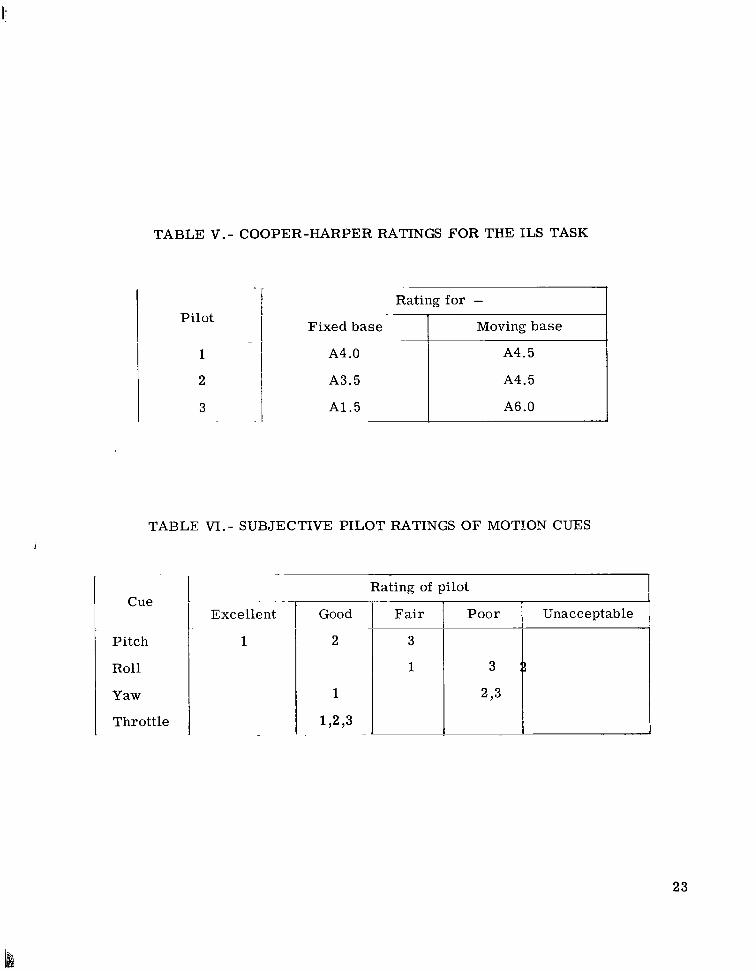
TABLE V.- COOPER-HARPER RATINGS FOR THE ILS TASK
Rating for -Pilot
Fixed base 1 Moving base I 1 A4 .O A4.5
2 A3.5 A4.5
3 A1.5 A6 .O
TABLE VI.-SUBJECTIVE PILOT RATINGS OF MOTION CUES
Rating of pilot Cue
Excellent Fair Poor Unacceptable I Pitch 1 3
Roll 1 3
Yaw 293
Throttle
23
i

--
Computer derived inDut
- * f * f.* f.* Centroid fc.x' c,y Body to inert ial 1.x' 1.Y-.-P transformationtransformation low frequency components.
f - - r'*' Variation n ign pass transformation L about 1g f i l ter high frequency components
L I .
=- Signal &$#$' 'ilZ ~ shaping -Inertial to P', q', r'
network 9, 8. @ body I --Sum of airplane p, q, r Transform to 6.6, i- Angular lead -
..1 -
Artif icialf and rates rl. e. Qb Euler rates 9, e, 0- compensation 9.6. Q
yaw error
Angular channel drives through
h h
actuator extension transformation
Translational channelranslarlonal 2. 9,2 drives through
lead 1-1 actuator extension Iompensation transformation,
-(a)Complete diagram.
Figure 1.- Detailed block diagram of washout circuitry.
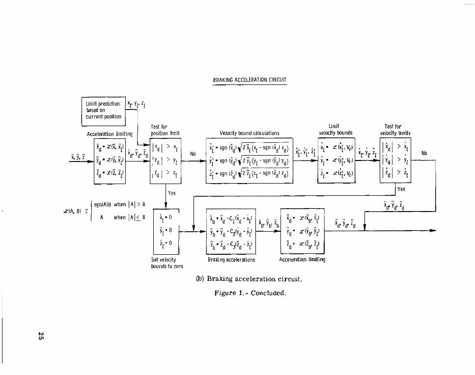
BRAKING ACCELERATION CIRCUIT
Limit prediction zz based on current position
A I > B Y $
YesYes
sgn(A) B when
A when .. 1. ' x = Zliv iz'A l i B $ = O X b g Xd -c,(id -i2 i , j ; , ; "d .. ..
b b b .. Yd' i b j;d - - iz' = Yd= x(j;b'i'Z) .. ..
3 Ziz=0 'bmZd -c1; d - i ) t'd = x(t'v22
LI
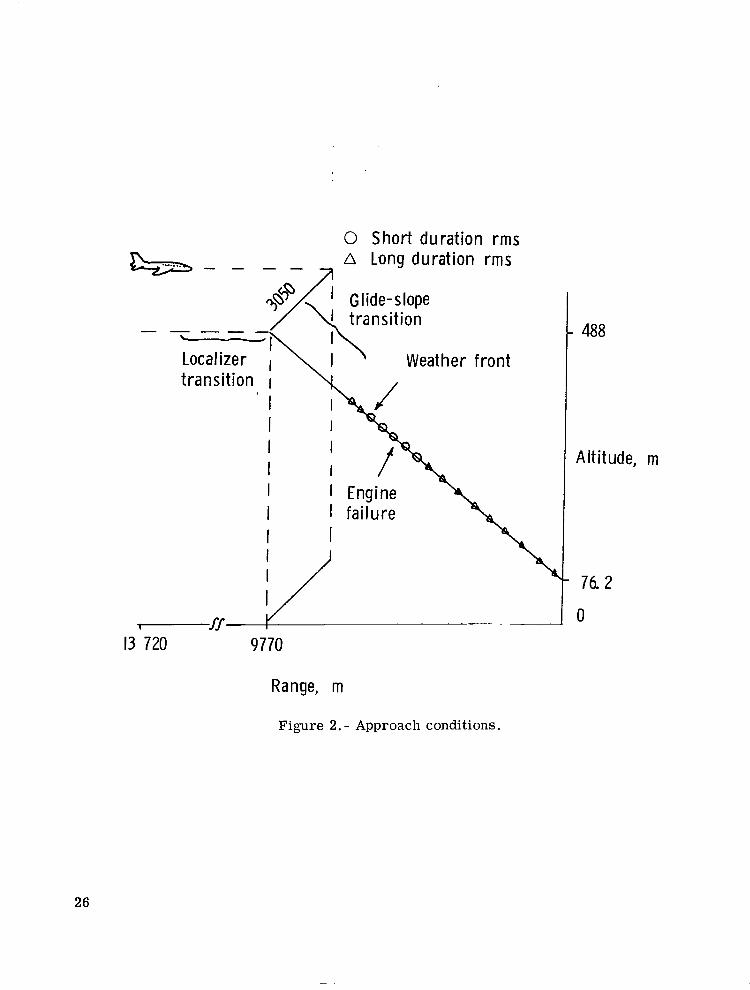
0 Short duration rms A Long duration rms
1 I I:ride-s lope
insition 1488
Weather front
m
13 720 9770
Range, m
Figure 2. - Approach conditions.
26

- .2,L L t , : 11 J
I . . . I
i j',
- 1 ;; L I i - - . ..I j, J J J 4'4 ., > O ' J
I . - . -i-_ . I ., I.-. '1c;i n '. i
w11m-t: &c)
Figure 3. - Standard approach condition time histories.
27

I
;si,
i . . . . . . . . . . . . . . . . . . . . . . . I. I ir r
. J i J c l i 'i 3
. . . . . . .i .I: .. J
Time (x:c)
Figure 3. - Continued.
28
- - -
t Flight Data - Washout Commands
i i 5
Time (xc)
I. i4U
Tinu: (5.4
Figure 3. - Continued.
29

--
-tFlight Data
. . . . . . . . . 1fJL i 3C
i s
I'1LJ * )
- - l C i
- Waslinut Commands
I. . . . 2 1 G
Time (set)
Tinie (sec)
1. . . . . . . . . . . 1 ... ... J2 '2 rj 2'35 ?Li ci
. . .I . . . . . . . . . . ii2.>r; 7 '3I' L J 2LiG
..I . . . . .i 2 '3 !i 2L iL
Figure 3. - Continued.
30
-;'I--+
a4 . i; tj
V"I. 1:mt:@c-.c)
Figure 3. - Continued.
31

t Flight Data - Washout Cminrand:,
-.. . . . . . . . . .i .., -?I 1 s!J
-.r . I .
0 ’, 15
Time (sec)
I
i 1- - 1 5 L-....... I . . . . . . . . ._ . . . ..._.1 . . . . . Fjcj ‘7 s 9 0 I OLi I I t i
Time (sec)
Figure 3. - Continued.
32

--
t Flight Data - Washnu t Coinmands
- 2 r
- 1 c
- .2 L .. . . . . . . . . . . . . . I I . 1. . . . . . . . . I ........ _II i ? O i '3 ti - 1Liti 151; IEiG i7G 29c
Time @c)
I I I- I . . . . . I.. . . . . . . . . . . . . . . . . . . . . . . i r j i 'ii- i.qii I. 5ri I65 I?; is5 .
T h e (5.C)
Figure 3 . - Continued.
33
.f Flight Data - Washout Commands
I
I
... . . . . . . . . . . . . . . . . . . . . . . . .;l1 1 8 5 i 3:; 2 'J 2
. . . 1 . . ... cIr1r ' . . . . . . . . . . . . . . . . II 190 1313 L J ' J :til
TilTlt: @ec)
Figure 3. - Concluded.
34
22!j
4-Flight Data - W a s h u t Cominands
i .... ...... . . . . . . . . . . .1 I 70 $5 tYj
1 - . . . . . 5::
- - q . . . 1 i G 13 fi I!
Time ( S K )
Figure 4. - Weather front approach condition time histories.
35

+ Flight Data
I
J S. . . . . . . . . -. . . . . . . . . . . ' I rJ 13 ij
Time. @iec]
Figure 4. - Continued.
36
+ Flight Data - Washnut Commands
- " 1 0 L. . . . . . . .--. . . . . . . . . . _ _ . . . . . . . . . . . I ....1 i 2 ri 1. 3 S 1Lis 1 jr; 165 173 tat i
Tinw (xc)
- - q L . . . -. . . . . . . . . . . . . . . . . . .I . . . 1.. -. . . . . 1- . . . . . . . Ji 1 i 213 I3Li iLilJ 1. b i; 165 i. 7 ii iaii
Tin.,e (see) Figure 4.- Continued.
37

t Flight Data
-'c- 1
I
. i t
- - 2 L.... i 1B i j i 30
i 'j
... 3 rk v
- Washout Commands
Time (sec)
Tillle. (sec)
Figure 4.- Continued.
38
..-.. . ..- ..-- ._. .. . .. ... . -.

t Flight Dam
. . . . . . . I . . I ....I jij 4ii jr;
Time (sec)
q-II
I.. - 1. ...... I... . i :'J ' 3 L: q G
r f i l l ? C (sec)
I . . 31i
Time (sec) Figure 4. - Continued.
39
+ +
t Flight Data
”l-
-T I
- . . . . . . . . ..-:L...I i 6 5 7 5 Y ti
1 ‘15
Fjrj 7 9 flu
- Washout Cnmniands
+ -t
i+
.s :r,
Time (sec)
..i-. . . . . . . . . . 1 . .
d ’J I I . ti Time (sec)
-*
3 I rj . . .
flij
G . . . . . . .I ...... I
t t G I 2 0
Time (sr-c)
Figure 4. - Continued.
40

+Flight Data - Washout Commands
I
I
- 1 . I . . I. L - . i ~ . . I 13 Ij i Lis I S 0 163 Z7G 19Li
'Time. (sc:c]
Figure 4.- Continued.
41

t Flight Data - Washout Commands
^c- - 1
- - 1 2 i........ 3 80
I
i SIL. . . . . . . i. . . . . . . . .- - l c ; Yj i 3 r j
. . . . . . . . .I2 I ;j
. . . . . . . .1.. . . . . .___.I I . .2!J f j x n 2 ;I Si
Time (xc)
Figure 4.- Concluded.
42

. . . . . . . . .1 1 ;;
1.. .. 2 5
I
1.. . . . . . . 3ti
1 ..... iL
?
- .13 L. . . . . . .
G I. :;i ; IJ'J
. . . . . . r i,
I.... ._..L O
Time (sec)
Figure 5.- Engine-out approach condition time histories.
43
f Flight Data
I
Ii . . . . . . . .
:3 iJ l I ; S
!
i i C j 1 i i;
!
Time (sec)
Figure 5. - Continued.
44
1

+ Flight Data - Washout Commands
- - 2 L..... I I - I 1 . . . . . . . . - . . . . . . . . _11 120 i 3 0
:r;
I_: L . d U
- . 1 . i I 3 i j
I l i U 150 - 160 27G 19ti
Time (sec)
. . 1 . . . . . . . . . . . . . . 1 . . . i-7-c .. _Ii I 145 5 ;1: 1 6 6 27''I d
Time (.5ec)
Figure 5. - Continued.
45
+ Flight Data - Washant Commands
I
1 I- - 2 ...... .- i . . . . . . . . . ............ Z R O 13ri 22Yj 7.3s
Time (sec)
A I
Lrinle (xc)
Figure 5. - Continued.
46
.' 1Iu
<T L . . . . - - L 1 G 3Li
1 I I. . . . . . -I C :!J 311
- . 1 G L_ _ _ 1 . . . 1 ..
0 2G 33
Time (zc)
Figure 5. - Continued.
+'+
i........ . i . 't i; Lr;
. I.4c
1 . . . . . I'ic 5ri
47
I.

4- Flight Data - Washout Commands
++ z r + +i
lt- i
- .?;jL ...-. . . . 1.' 1 ;
1 . . . i ........... i.- . . . . __.......1.- ...... i . . . . . i 1 '7 5 q fi :r; 1 5 3 1 1i3 1?U
Time (sec)
I
- - 1 u . . 1 . t I . . . . . I ....... 1 i i G '73 13 0 2r j 1 Glj I 1 G 1 ? G
Time (sec) Figure 5. - Continued.
+ Flight Data -Washout Commands . .
++ -e f + ir ++
49
4- Flight, D a e - Wasbout Cnxninands
'Firm (zx) I
.. i 01 I
- = Ii l l
_..1 13 r,:
'rime (mc)I I Figure 5. - Concluded.
50
- : I
0 1 2 3 4 5 6 7 8 9 1 0 1 1
, Time, sec
Figure 6. - Accelerometer output documenting turn-around bump in roll.
51

!
i
! 1 (a) Simulated aircraft response.
Figure 7.- Response to an aileron pulse input,
52

+ Flight Data - Washout Commands
-2c I . . 1 - I. ........... 1s 16 2 c
Time, sec 1s
" 5 Q)sQ)
- o r : ts
-1: 1 .. . . . 2 c
Time, sec n
I-.......... 1: . . . . . . . . . ..... __.... -. I __ L' 10 15
Time, sec (b)Washout response with 0.1 rad/sec frequency.
Figure 7.- Concluded.
53

VaJsaJ m d
-t Flight Data - Washout Commands
I:j. . . . . 1 . . . . . l...- ....... . . . . . . . . . . . . 5 I C ' 15 2G
Time, sec
i c.c ............... -
I
.I C L .
c Time, sec
- .? I:L -I . . . . . . 1-. . . . . . . . . 5 I C
Time, sec
Figure 8.- Washout response with 0.3 rad/sec frequency.
54
-t- Flight Data - Washout Commands
N 2 c0 a,v)3 i s -u
75 a,L r
s L v)m a,E
- 1 c
-2c _ _ - ... I . . . . . . - . . . -I. .. . . . .......... - -. _II I '1 ::
6' lr: ;IC L V 3G
Time, sec
r; . . . . . . . . . . . . . . . - I ..- . 1-. ...... I ..................
I,
1i'
i- I CT 15 :r! I:; 7'' L C' 3 Ct
Time, sec
/f "\
I 1 I - 1 - 1 - 1 1 G 15 2 o 2 5 30
Time, sec e
Figure 9.- Washout response with 0.5 rad/sec frequency.
NASA-Langley, 1975 L -9984 55

NATIONAL AERONAUTICS AND SPACE ADMINISTRATION
WASHINGTON. D.C. 20546 POSTAGE A N D FEES P A I D N A T I O N A L AERONAUTICS A N D
OFFICIAL BUSINESS PENALTY FOR PRIVATE U S E 1300 SPECIAL FOURTH-CLASS RATE
SPACE A D M I N I S T R A T I O N 451
U S M A I L BOOK
If Undeliverable (Section 158POSTMAST~R : Postal Mnnnal) Do Not Return
“The aeronautical and space activities of the United States shall be conducted so as t o contribute . . . t o the expansion of human knowledge of phenomena in the atmosphere and space. T h e Administration shall provide for the widest practicable and appropriate dissemilzdtiom of information concerning its activities and the results thereof.”
-NATIONALAERONAUTICSAND SPACEACT OF 1958
NASA SCIENTIFIC AND TECHNICAL PUBLICATIONS TECHNICAL REPORTS: Scientific and technical information considered important, complete, and a lasting contribution to existing knowledge.
TECHNICAL NOTES: Information less broad in scope but nevertheless of importance as a contribution to existing knowledge.
TECHNICAL MEMORANDUMS: Information receiving limited distribution because of preliminary data, security classification, or other reasons. Also includes conference proceedings with either limited or unlimited distribution. -CONTRACTOR REPORTS: Scientific and technical information generated under a NASA contract or grant and considered an important contribution to existing knowledge.
TECHNICAL TRANSLATIONS: Information published in a foreign language considered to merit NASA distribution in English.
SPECIAL PUBLICATIONS : Information derived from or of value to NASA activities. Publications include final reports of major projects, monographs, data compilations, handbooks, sourcebooks, and special bibliographies.
TECHNOLOGY UTILIZATION PUBLICATIONS: Information on technology used by NASA that may be of particular interest in commercial and other-non-aerospace applications. Publications include Tech Briefs, Technology Utilization Reports and Technology Surveys.
Details on the availability of these publications may be obtained from:
SCIENTIFIC AND TECHNICAL INFORMATION OFFICE
N A T I O N A L A E R O N A U T I C S A N D SPACE A D M I N I S T R A T I O N Washington, D.C. 20546