Embed Size (px)
DESCRIPTION
http://web.archive.org/web/20130525222936/http://www.kallmanclassic.com/microsites/caafiexpo2011/presentations/Environment%20Team/Bulzan%20CAAFI%20NASA%20Presentation%2011-30-11.pdfYes, I backed it up.
Citation preview

NASA Alternative Fuel Research CAAFI 2011 General Meeting
November 30 – December 1, 2011Washington, DC
Dan BulzanNASA Glenn Research Center

C b ti CFD M d D l t d V lid ti E i t
Research to Support Alternative Fuel Development
• Combustion CFD Mode Development and Validation Experiments to allow development of fuel flexible low emissions combustors for future engines
• Alternative Fuels Research Lab fuel thermal stability measurements and experiments to optimize Fischer-Tropsch process for jet fuel production
• Low Emissions Fuel Flexible Combustor Concept Development to develop low emissions combustion concepts capable of operating on a variety of fuels
• Ground-based Engine Tests to evaluate alternative fuel effects on performance and emissions under real operating conditions
• Altitude Simulation Laboratory (PAL) Tests to examine fuel effects• Altitude Simulation Laboratory (PAL) Tests to examine fuel effects on contrail ice formation
• Airborne, Cruise Altitude Experiments to evaluate fuel effects on i i d t il f tiemissions and contrail formation

NASA Subsonic Transport System Level Metrics…. technology for dramatically improving noise, emissions, & performance
3

Low Emissions Combustors for N+2Environmentally Responsible Aviation Project
Development of fuel flexible low emissions combustor concepts to meet 75% LTO NOx below CAEP 6
• Contracts with General Electric and Pratt and Whitney to develop sector rig• Contracts with General Electric and Pratt and Whitney to develop sector rig concepts for testing in the NASA High-Pressure Combustor Facility
– P&W: Working on both Rich Burn (Talon-X based) and Lean Burn Concepts
GE W ki d d L B TAPS C t– GE: Working on advanced Lean Burn TAPS Concepts
• NASA also working collaboratively with several companies on alternative concepts for flametube testing and optional sector rig development and testing of a io s M ltipoint Lean Di ect Injection Conceptsof various Multipoint Lean Direct Injection Concepts
– Goodrich/Delevan
– Woodward FST
– Parker Hannifin Corporation
• Full Annular Rig testing of at least one concept
• Proposed core engine test in 2015
4
Low Emissions Combustors for N+3Subsonic Fixed Wing Project
• Combustion CFD Model Development and A li tiApplication
• Validation ExperimentsValidation Experiments
• Low Emissions Combustion Concepts
– N+3 Goals (Subsonics Fixed Wing and Supersonic Projects)
• Active Combustion Control
• Alternative Fuels5
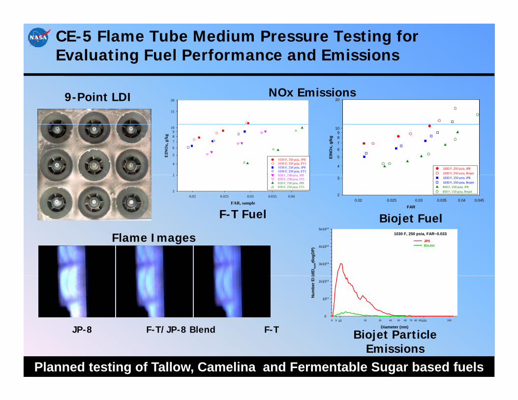
CE-5 Flame Tube Medium Pressure Testing for Evaluating Fuel Performance and Emissions
15
20 20NOx Emissions9-Point LDI
EIN
Ox,
g/k
g
3
4
5
6
789
10
1030 F, 350 psia, JP81030 F, 350 psia, FT11030 F, 250 psia, JP81030 F, 250 psia, FT1850 F 250 psia JP8
EIN
Ox,
g/k
g
4
5
6
789
10
1030 F, 250 psia, JP81030 F, 250 psia, Biojet
FAR, sample0.02 0.025 0.03 0.035 0.04
2
3 850 F, 250 psia, JP8850 F, 250 psia, FT1650 F, 250 psia, JP8650 F, 250 psia, FT1
FAR0.02 0.025 0.03 0.035 0.04 0.045
2
3 1030 F, 150 psia, JP81030 F, 150 psia, Biojet850 F, 150 psia, JP8850 F, 150 psia, Biojet
F-T Fuel Biojet Fuel
(dEI
num
dlog
DP)
3x10¹⁴
4x10¹⁴
5x10¹⁴
1030 F, 250 psia, FAR~0.033
JP8BioJet
Flame Images
JP 8 F T/JP 8 Bl d F T Diameter (nm)
8 9 20 30 40 50 60 70 80 90 20010 100
Num
ber E
I (0
1014
2x10¹⁴
JP-8 F-T/JP-8 Blend F-T Diameter (nm)
Biojet Particle Emissions
Planned testing of Tallow, Camelina and Fermentable Sugar based fuels

Engine Fuel Test Summary
Pratt and Whitney Geared Turbofan Engine Demo—January 2008• JP-8, 50:50 F-T/JP-8 blend • Test stand mounted engine• Performance + emissions measurements
Pratt and Whitney 308 Alternative Fuel Test—March 2008• JP-8, 50:50 F-T/JP-8/blend and F-T• Test stand mounted engineg• Performance + emissions measurements
Alternative Aviation Fuel Experiment—January 2009• FT, blends, and JP-8• CFM-56 on NASA DC-8• Performance and complete emissions
Alternative Aviation Fuel Experiment II—January 2011•Biofuel, FT, blends, and JP-8• CFM-56 on NASA DC-8• Performance and complete emissions• Additional tests to support SAE E-31 Particle Measurement Standard Subcommittee

AAFEX-II: HRJ Fuel Emission Characterization
Location: NASA Dryden Aircraft Operations Facility (DAOF)Palmdale, California
Dates: March 20 – April 2, 2011
Aircraft: NASA DFRC DC‐8, CFM‐56‐2C engines
Fuels: *Standard JP‐8*Tallow‐based HRJ & 50% Blend w/JP‐8Tallow based HRJ & 50% Blend w/JP 8*Coal‐based FT & Coal‐based FT w/1000ppm S added
Runtime: 11 separate Emissions Tests, 30.5 hrs total run time
Measurements: Certification gases, smoke, HAPS, PM number, size, mass, composition, black‐carbon content, and morphology
S NASA S b i Fi d Wi P j t FAA Ai FSponsors: NASA Subsonics Fixed Wing Project, FAA, Air Force
Participants: AEDC, AESO, AFRL, ARI, GRC, LaRC, MIT, MST, MSU, PSU
E‐31 Group: UTRC, EPA, Rolls, GE, TSI, NRC‐Canada, P&W

Fuel Characteristics
Test JP8 (1) Shell FT Sasol FT HRJ
Sulfur Content (ppm Mass) 100 0 0 0Sulfur Content (ppm Mass) 100 0 0 0
Aromatics (% vol) 21.8 ~0 0.4 ~0
E d P i t (°C) 300 268 206 225 254End Point (°C) 300 268 206 225 254
Flash Point (deg C) 46 41 43 52
(k / )Density (kg/L) 0.811 0.738 0.761 0.759
Freezing Point (deg C) ‐53 ‐54 ‐78.5 ‐49
Hydrogen Content (% mass) 13.5 15.5 15.0 15.3
Heat of Combustion 43.3 44.4 44.1 44.1
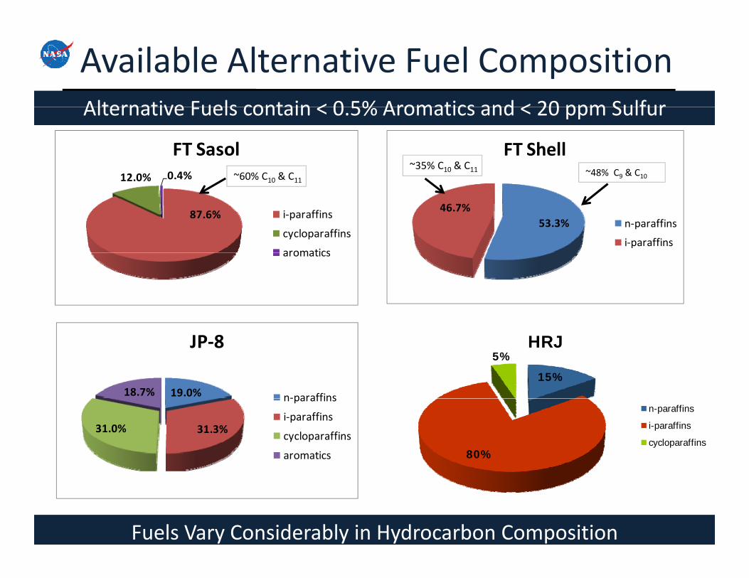
Available Alternative Fuel CompositionAlternative Fuels contain < 0 5% Aromatics and < 20 ppm Sulfur
12.0% 0.4%
FT Sasol FT Shell~48% C9 & C10~60% C10 & C11
~35% C10 & C11
Alternative Fuels contain < 0.5% Aromatics and < 20 ppm Sulfur
87.6%
12.0%
i‐paraffins
cycloparaffins
aromatics
53.3%46.7%
n‐paraffins
i‐paraffins
% 10 11
aromatics
19.0%18.7%
JP‐8
n‐paraffins
15%
5%HRJ
31.3%31.0%
n‐paraffins
i‐paraffins
cycloparaffins
aromatics 80%
n-paraffins
i-paraffins
cycloparaffins
Fuels Vary Considerably in Hydrocarbon Composition

AAFEX‐II Project Objectives
1) Evaluate alt fuel effects on engine performance and fuel‐handling equipment
2)Determine the effects of alt fuels on engine and APU PM and gas phase emissions
3) Investigate the role of sulfur in regulating volatile aerosol formation in engine exhaust plumes
4) Examine the effects of sample line chemistry and particle losses on emission measurements
5) Conduct tests to support SAE E‐31 development of standard exhaust sampling methodsp g
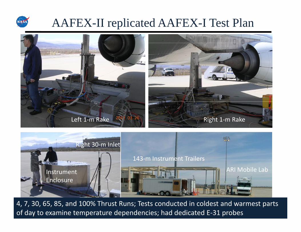
AAFEX-II replicated AAFEX-I Test Plan
Left 1‐m Rake Right 1‐m Rake
143‐m Instrument Trailers
Right 30‐m Inlet
143 m Instrument Trailers
Instrument Enclosure
ARI Mobile Lab
4, 7, 30, 65, 85, and 100% Thrust Runs; Tests conducted in coldest and warmest parts of day to examine temperature dependencies; had dedicated E‐31 probes
100
%)
HRJ Blend
1E15
mg/
kg)
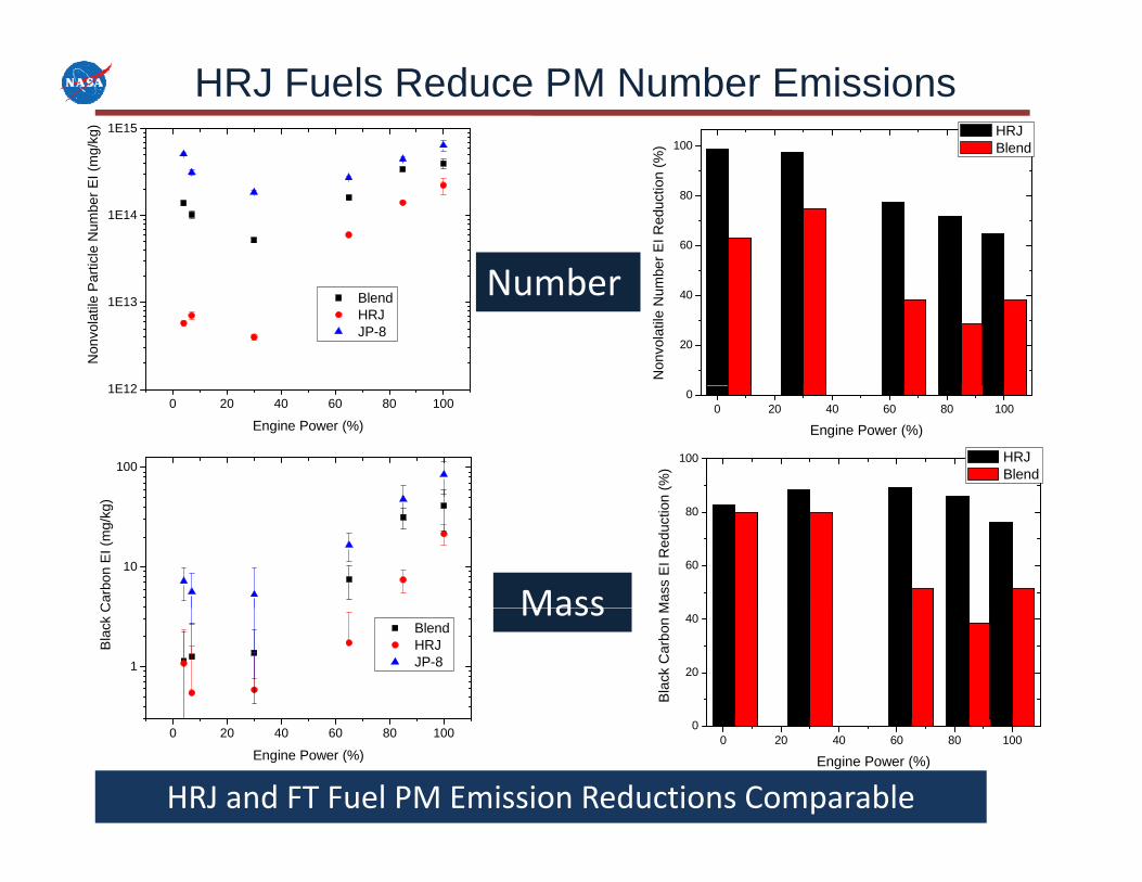
HRJ Fuels Reduce PM Number Emissions
60
80
ber E
I Red
uctio
n (
1E14
rticl
e N
umbe
r EI (
m
N b20
40
Non
vola
tile
Num
b
1E12
1E13 Blend HRJ JP-8
Non
vola
tile
Pa Number
0 20 40 60 80 1000
Engine Power (%)
0 20 40 60 80 1001E12
Engine Power (%)
100
n (%
)
HRJ Blend100
60
80
Mas
s E
I Red
uctio
n
10
Car
bon
EI (
mg/
kg)
Mass20
40
Bla
ck C
arbo
n M
1
Blend HRJ JP-8
Bla
ck C Mass
0 20 40 60 80 1000
Engine Power (%)
0 20 40 60 80 100
Engine Power (%)
HRJ and FT Fuel PM Emission Reductions Comparable

HRJ also Reduces Volatiles in Downstream Plume
100
%)
HRJBlendN b t
1E16
JP-8 HRJ Blend
Num
ber E
I (#/
kg)
40
60
80
er E
I Red
uctio
n (%
BlendNumber at 30 m
1E15
Tota
l Aer
osol
N
0
20
40
otal
Aer
osol
Num
b
0 20 40 60 80 1001E14
Engine Power (%)
0 20 40 60 80 100-20
To
Engine Power (%)
100
%) HRJ
Blend
60
80
ss E
I Red
uctio
n (% Blend
100 JP-8 HRJ Blend
ass
EI (
mg/
kg)
Mass at 30 m
20
40
Tota
l Aer
osol
Mas
10
Tota
l Aer
osol
Ma
0 20 40 60 80 1000
Engine Power (%)0 20 40 60 80 100
1
Engine Power (%)
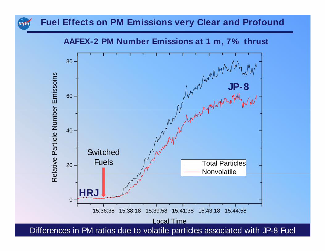
Fuel Effects on PM Emissions very Clear and Profound
AAFEX-2 PM Number Emissions at 1 m, 7% thrust
80ns
60
er E
mis
soin
JP-8
40
cle
Num
be
20
lativ
e Pa
rti
Total ParticlesNonvolatile
Switched Fuels
0
Re Nonvolatile
HRJ
15:36:38 15:38:18 15:39:58 15:41:38 15:43:18 15:44:58
Local TimeDifferences in PM ratios due to volatile particles associated with JP-8 Fuel
20 25
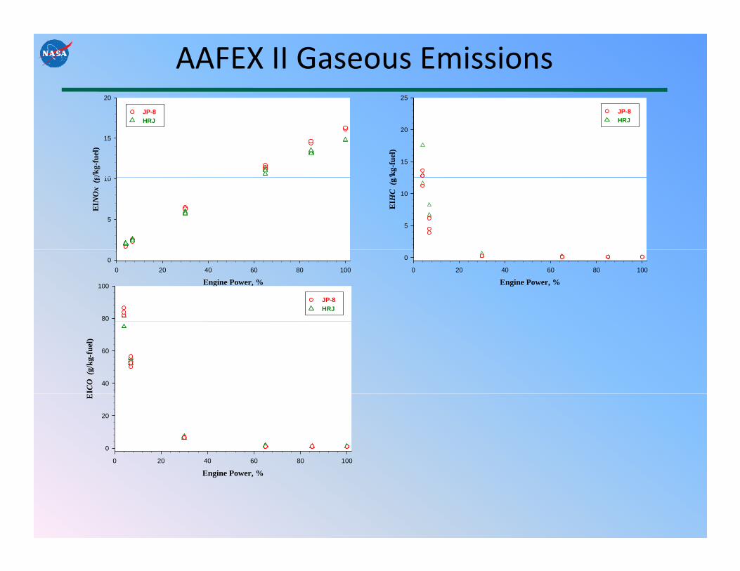
AAFEX II Gaseous Emissionsg/
kg-f
uel)
10
15
HRJJP-8
/kg-
fuel
)
15
20HRJJP-8
EIN
Ox
(g
5
10
EIH
C (
g/
5
10
Engine Power, %0 20 40 60 80 100
0
Engine Power, %0 20 40 60 80 100
0
80
100
HRJJP-8
ICO
(g/
kg-f
uel)
40
60
0 20 40 60 80 100
E
0
20
Engine Power, %

Sulfur Plays Significant Role in Volatile PM Formation
Relatively high ambient temperature suppressed volatile formation but
1E16
EI (
#/kg
)
volatile formation, but difference still profound
1E15
eros
ol N
umbe
r
1 1
20 ppm S 1000 ppm STo
tal A
e
100
I (m
g/kg
)
0 20 40 60 80 1001E14
Engine Power (%) 10
Aer
osol
Mas
s E
1
20 ppm S 1000 ppm S
Tota
l A40 mg/kg ~ 1% S(IV) conversion to S(VI)
0 20 40 60 80 1001
Engine Power (%)
AMS measurements indicate volatile mass mostly sulfate
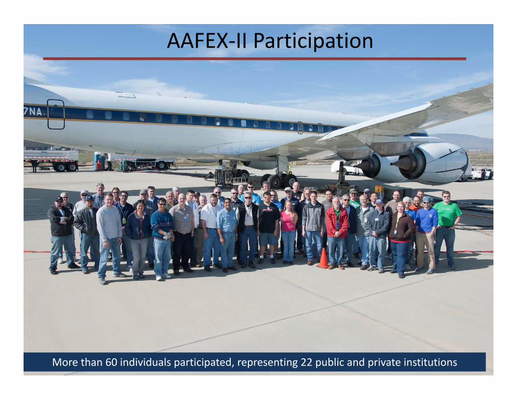
AAFEX‐II Participation
More than 60 individuals participated, representing 22 public and private institutions

AAFEX II Workshop
• Friday, January 13, 2011• Immediately following the AIAA AerospaceImmediately following the AIAA Aerospace
Sciences Meeting• Gaylord Opryland Resort and Conference
C tCenter• Nashville, Tennessee• 8:00 am 2:30 pm• 8:00 am – 2:30 pm• Presentations from participating groups of
data collected during the experiment da a co ec ed du g e e pe e• No registration fee• If interested in attending, please send an g p
email to: [email protected]

Fuel Effects on Contrails being Studied in Altitude Chamber
Tests examine the links between soot emissions/properties and ice formation
VacuumExhaust
Tests examine the links between soot emissions/properties and ice formation
Liquid Nitrogen
ChamberOPC
Vaporizer/
Flow control valvesOPC
Humidifier
Vaporizer/Heat
ExchangerXenon Source Spectrometer
OPC
Humidifier
P ~ 1 atm, T~673 K Simulated Exhaust Emissions
• Flow‐through chamber can simulate conditions up to 50,000 ft• Particles monitored using Optical Particle Counters and Light Scattering• Can control soot size, number density, and sulfate and organic coatings

High PM Concentrations Required for Ice Formation
“Contrail” visible for CN > 1e6/cm3
ExhaustJet
LightSource
SootSoot4% RH
• Tests are being conducted with ACCRI co‐sponsorship and in collaboration with AerodyneTests are being conducted with ACCRI co sponsorship and in collaboration with Aerodyne, which is using the data to validate contrail model• Oct tests will explore particle size and solubility effects on ice formation• Will conduct future tests using high‐pressure burner and alternative fuels
Alternative‐Fuel Effects on Contrails and Cruise EmiSSionsACCESS

ACCESS Objectives
1. Characterize cruise altitude soot and gas phase emissions from aircraft as they burn a variety of fuels, including JP-8, HRJs and possibly FT fuels.fuels, including JP 8, HRJs and possibly FT fuels. May be limited to blends because of certification issues.
2. Investigate the role of soot and fuel sulfur in regulating contrail formation and the microphysical properties of the ice particlesmicrophysical properties of the ice particles.
3. Measure the soot and gas-phase emissions and contrail characteristics in exhaust from commercial aircraft at cruise in air-traffic corridors

ACCESS Status
Location: NASA Dryden Aircraft Operational Facility,Palmdale, California
D S i i 2013Dates: Starting in 2013Sponsors: NASA, other collaborations are welcomeChase Aircraft: Dryden, Glenn, and Langley aircraft are being consideredSource AC: NASA DC‐8, others are being consideredMeasurements: Aerosol number, size, composition, volatility
Cloud particle size, number, images, water contentCO2, CO, NOx, O3, water vapor
Fuels: JP‐8, Biojet and FT blends, Biojet and FT neat if possible

Questions?Q