Embed Size (px)
Citation preview
NAS Document NO. 200404-23 Rev. 10/2016 -1- North American Signal Copyright © September 4, 2003
NAS
MICRO DATA ANALYZER II
OPERATIONS AND MAINTENANCE
MANUAL
North American Signal Systems 605 NW 53rd Ave.
Suite A-17 Gainesville, FL 32609
Phone: (800)-201-5566 www.nasignal.com

NAS Document NO. 200404-23 Rev. 10/2016 -2- North American Signal Copyright © September 4, 2003
Introduction ......................................................................................................... 4 MDA II Hardware Configuration ......................................................................... 5
Specifications: ................................................................................................... 5 MDA II Chassis .................................................................................................. 7 MDA II Board Layout ......................................................................................... 8 Input- Output Interface ...................................................................................... 9
TB1 Battery Monitoring WAGO Terminal ....................................................... 9 TB2 Analog Input WAGO Terminal ................................................................ 9 TB3-4 Digital Inputs 1-8, 9-16 WAGO Terminal ........................................... 10 TB5 Current Sensor WAGO Terminal .......................................................... 11 TB6 Power- Network- Output WAGO Terminal ............................................ 12 ATCS RS232 Serial Port.............................................................................. 12 RS232 Port .................................................................................................. 13 External Radio RS232 Port .......................................................................... 13 Maintenance Ports Serial ............................................................................. 13 Internal Compact Flash ................................................................................ 13
Peripheral Devices .......................................................................................... 14 DTMF Radio ................................................................................................ 14 External Modem VHF Radio ........................................................................ 14 External Audio Out ....................................................................................... 14 Current Sensor Modules .............................................................................. 15
MDA II Ordering Reference Information .......................................................... 16 MDA II Software Configuration ........................................................................ 17
MDA II Program File Structure ........................................................................ 17 Boot Program ............................................................................................... 17 Executive Program ...................................................................................... 17 Application Program .................................................................................... 17
Loading Application and Executive Program Files .......................................... 18 Maintenance Terminal Password ................................................................. 18 Crossing Analyzer Application ..................................................................... 19 Administration Password (Firmware Load) .................................................. 20
Creating Application Program Files ................................................................. 21 Cellular Radio Programming (Optional) ....................................................... 22 Data Radio Programming (Optional) ............................................................ 22
System Installation and Set Up........................................................................ 23 Initial site Set Up ............................................................................................. 23 Analyzer Alarm Criteria ................................................................................... 23
Crossing Application .................................................................................... 23 Maintenance and Diagnostic Menus ............................................................... 26
Terminal Interface ........................................................................................... 26 Menus Recorder Application ........................................................................... 27
Maintenance Terminal Password ................................................................. 27 Main Menu ................................................................................................... 27
NAS Document NO. 200404-23 Rev. 10/2016 -3- North American Signal Copyright © September 4, 2003
(1) Log Menu ............................................................................................... 28 (2) Maintenance Menu ................................................................................. 30 (3) Lamp Calibration .................................................................................... 34 (4) Set Time and Date ................................................................................. 35 (5) Reset ...................................................................................................... 35 (6) Palm Mode On/Off .................................................................................. 35 (7) Log Off.................................................................................................... 35 (9) FRA Inspection Mode ............................................................................. 36 (D) Disable FTP Send .................................................................................. 41 (E) Enable FTP Send, Clear FTP Counter ................................................... 41 Maintenance Mode Switch ........................................................................... 42
LED Indicators ................................................................................................. 43 Battery Monitor Indicators: ........................................................................... 43 Analog Input Indicators ................................................................................ 43 Digital Input Indicators ................................................................................. 43 Status Indicator ............................................................................................ 43 Auxiliary Indicators ....................................................................................... 43
Maintenance and Troubleshooting .................................................................. 44 Troubleshooting Checklist ............................................................................... 44
Terms and Conditions of Sale ......................................................................... 45 Appendix ........................................................................................................... 48

NAS Document NO. 200404-23 Rev. 10/2016 -4- North American Signal Copyright © September 4, 2003
Introduction The Micro Data Analyzer II unit (MDA II) is a processor based analysis system utilized for applications involving supervisory control and data acquisition. The system can be configured for interface to wayside equipment to allow for event recording, real time health monitoring, remote control and diagnostic port interface. The unit can operate independently at a wayside facility or be configured with a host of remote telemetry packages to allow for centralized reporting. The MDA II is software configurable by the user for the specified application. In large applications, the Micro Data Analyzer can be connected by way of a RS422 Serial loop to a Universal Data Analyzer or additional Micro Data Analyzers to offer additional capacity or connectivity to a remote facility. Smaller in profile but not on functionality than the Universal Data Analyzer, the MDA II is designed to provide you with a cost effective solution to your remote control and monitoring requirements. Equipped with 16 Isolated Analog Inputs, 16 Digital Inputs and 4 relay-controlled outputs the MDA II is a cost effective solution for site analysis. Equip the MDA II with a 6 watt UHF/VHF DTMF radio transceiver operating on your licensed frequency provides control from the ground with a standard 2 way portable radio. Equipped with customer configured “voice annunciation features,” receive over the air command confirmation on your 2-way radio or base equipment.
Master - Slave up to 4 units located within 3000 feet of the master unit to provide a distributed monitoring platform at multiple sites.
The NAS Windows Configurator Program allows the user to easily configure the system to specifically satisfy location requirements.

NAS Document NO. 200404-23 Rev. 10/2016 -5- North American Signal Copyright © September 4, 2003
MDA II Hardware Configuration The Micro Data Analyzer II unit is a self-contained processor based motherboard configuration mounted in an Aluminum Chassis. The Chassis contains a removable cover accessing the system electronics. The chassis can be wall or shelf mounted. The cover includes detail identification of the systems interconnections. If you have to read this manual to obtain information, then we have done something wrong in the production process. Everything you need to know about the visual indicators and the detailed interconnect of the system is identified on the front cover. To access the system electronics, unscrew cover fasteners located on the left and right side of the cover. Depending on the system configuration ordered from the factory, the unit will contain additional module interfaces such as an internal DTMF Radio or a telemetry TCP/IP interface unit. The MDA II comes equipped with 16 Isolated Digital inputs, 16 Analog Inputs consisting of 4 Battery Monitors, 4 current sensor monitors, and 8 general-purpose analog inputs, along with 4 relay controlled outputs. Based around Motorola’s 68HC12 processor once used in 95% of the nation’s automobiles, the system is designed to work when the rest of your systems are not. Isolated with an Internal DC-DC Converter, the unit can operate on a wide range of Input voltages from 8-36 Volts DC. Specifications: Physical: Chassis: 12.5” L X 19”W X 3” D Environment: -40 to +71 Degrees C Inputs: (16) Analog- (4) Battery Monitors (4) Current Sensor (8) Multi Function (16) Digital Isolated
5 –40V AC or DC 3000V Isolation 6 Meg Ohm (Digital) 0-40V DC 3000V Isolation 1 Meg Ohm Impedance Isolation on Analog Inputs Battery Monitors 0-40 Volts .1Volt Incremental Settings Current Monitors-0-30 Amps AC or DC 25MA resolution
Outputs: 4 FBH Relays Contact Rating 10 Amps @ 100VDC 10 Amp @
125VAC Inductive Memory:
Compact Flash Card Standard 8GB (~24 Million Events)

NAS Document NO. 200404-23 Rev. 10/2016 -6- North American Signal Copyright © September 4, 2003
Power: DC-DC Converter Operating Voltage 8-36V DC, Isolated Ground Communication Ports: (1) Ext RS232 Radio Port- Isolated Power and
Communications (1) RS232 ATCS Port for interface to Spec 200
Compliant Radio (1) RS232 Port General Use Peripheral Interface (1) RS232 Port Maintenance Port Terminal
Interface Compact Flash Socket: (1) Socket Interface for external Compact Flash
Card. Data Export or Security interface for user authorization
DTMF Radio: Ritron DTX-Plus, 6 Watt 8 Channel Synthesized Wire Terminals: WAGO 12 or 18 way plug in connectors Wire Size 12 AWG—22AWG

NAS Document NO. 200404-23 Rev. 10/2016 -7- North American Signal Copyright © September 4, 2003
MDA II Chassis
1. On/OFF Power Switch 2. Power LED Indicator- Illuminated when DC-DC Converter is providing output power
(inside unit) 3. Carrier Detect LED- For Cellular/ Radio applications. Illuminated when unit is connected
to external network. 4. Health LED- Unit will flash when system is operating properly 5. Maintenance Mode Switch On/OFF- On Displays Maintenance Log On Maintenance
Menu screen disables alarm reporting. 6. Maintenance Terminal Port- RS232C DB9 Female serial interface application
programming and access to Maintenance Screens 7. Compact Flash Socket – Download Events and Reports 8. RJ45 10/100 Ethernet Adapter (Optional) 9. RS232C Ext Modem – Dial Up Adaptor 10. RS232C Ext Modem -VHF Radio Isolated DC Power 11. RS232 C Pass Through Port 12. RJ11- V.96 Internal Modem 13. ATCS Serial Port
12 Way WAGO Connector TB1 Battery Inputs
18 WAY WAGO Connector TB2 Analog Input
1
2
4
5
6
7
8
12
18 WAY WAGO Connector TB3 Digital 1-9
18 WAY WAGO Connector TB4 Digital 9-16
18 WAY WAGO Connector TB6 Power Network 12 WAY WAGO
Connector TB5 Current Sensor
10
9 11
13
3

NAS Document NO. 200404-23 Rev. 10/2016 -8- North American Signal Copyright © September 4, 2003
MDA II Board Layout A detailed layout of the MDA II analyzer PC board is shown below. Reference list for component layout is located in the Appendix.
1. DB9M ATCS Serial Port 2. RJ11- Line In Internal Modem 3. DB9M RS232 Pass Through Port 4. DB9M External Modem 5. DB9M RS232 External Radio Control Port 6. RJ45 10/100 Ethernet Port 7. DB9M RS232 Maintenance Port 8. External Compact Flash Socket – Standard 8GB Flash Card 9. Internal Compact Flash Memory Module
LED Indicator Panel
DC-DC Converter
1
2
3
4
5
6
7
8
9
NAS Document NO. 200404-23 Rev. 10/2016 -9- North American Signal Copyright © September 4, 2003
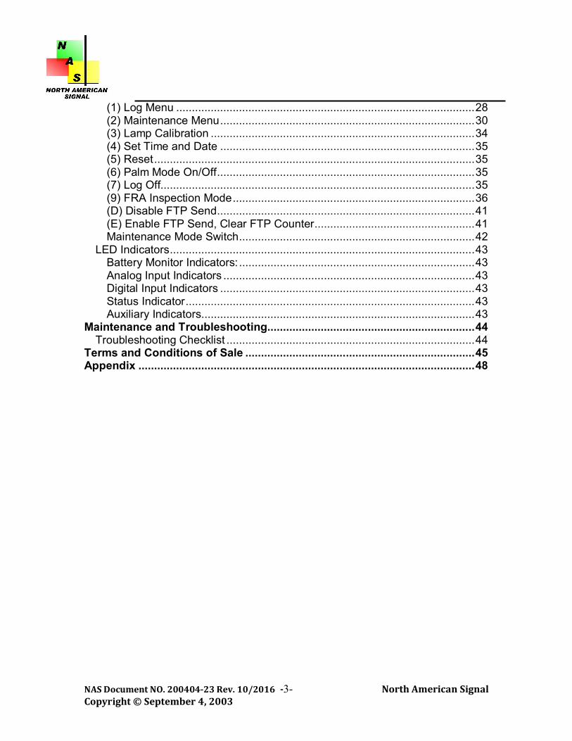
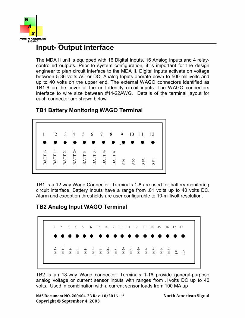
Input- Output Interface The MDA II unit is equipped with 16 Digital Inputs, 16 Analog Inputs and 4 relay- controlled outputs. Prior to system configuration, it is important for the design engineer to plan circuit interface to the MDA II. Digital inputs activate on voltage between 5-36 volts AC or DC. Analog Inputs operate down to 500 millivolts and up to 40 volts on the upper end. The external WAGO connectors identified as TB1-6 on the cover of the unit identify circuit inputs. The WAGO connectors interface to wire size between #14-22AWG. Details of the terminal layout for each connector are shown below. TB1 Battery Monitoring WAGO Terminal TB1 is a 12 way Wago Connector. Terminals 1-8 are used for battery monitoring circuit interface. Battery inputs have a range from .01 volts up to 40 volts DC. Alarm and exception thresholds are user configurable to 10-millivolt resolution. TB2 Analog Input WAGO Terminal TB2 is an 18-way Wago connector. Terminals 1-16 provide general-purpose analog voltage or current sensor inputs with ranges from .1volts DC up to 40 volts. Used in combination with a current sensor loads from 100 MA up
1 2 3 4 5 6 7 8 9 10 11 12
BA
TT 1
- B
ATT
1+
BA
TT 2
- B
ATT
2+
BA
TT 3
- B
ATT
3+
BA
TT 4
- B
ATT
4+
SP1
SP2
SP3
SP4
IN 1
- IN
1 +
IN
2-
IN 2
+ IN
3-
IN 3
+ IN
4-
IN 4
+ IN
5-
IN 5
+ IN
6-
IN 6
+ IN
7-
IN 7
+ IN
8-
IN 8
+ S
P
SP
1 2 3 4 5 6 7 8 9 10 11 12 13 14 15 16 17 18

NAS Document NO. 200404-23 Rev. 10/2016 -10- North American Signal Copyright © September 4, 2003
to 30 Amps can be monitored with resolution of 25MA. Inputs are equipped with 1 Meg Ohm Isolated input impedance for monitoring sensitive loads. TB3-4 Digital Inputs 1-8, 9-16 WAGO Terminal TB3 and TB4 provide 16 opto-isolated digital inputs. Inputs can range from 5 volts AC or DC up to 40 volts. Inputs are provided with isolated common return allowing direct connection to peripheral devices.
IN 1
- IN
1 +
IN
2-
IN 2
+ IN
3-
IN 3
+ IN
4-
IN 4
+ IN
5-
IN 5
+ IN
6-
IN 6
+ IN
7-
IN 7
+ IN
8-
IN 8
+ S
P
SP
1 2 3 4 5 6 7 8 9 10 11 12 13 14 15 16 17 18
IN 9
- IN
9 +
IN
10-
IN
10+
IN
11-
IN
11+
IN
12-
IN
12+
IN
13-
IN
13+
IN
14-
IN
14+
IN
15-
IN
15+
IN
16-
IN
16+
S
P
SP
1 2 3 4 5 6 7 8 9 10 11 12 13 14 15 16 17 18
NAS Document NO. 200404-23 Rev. 10/2016 -11- North American Signal Copyright © September 4, 2003
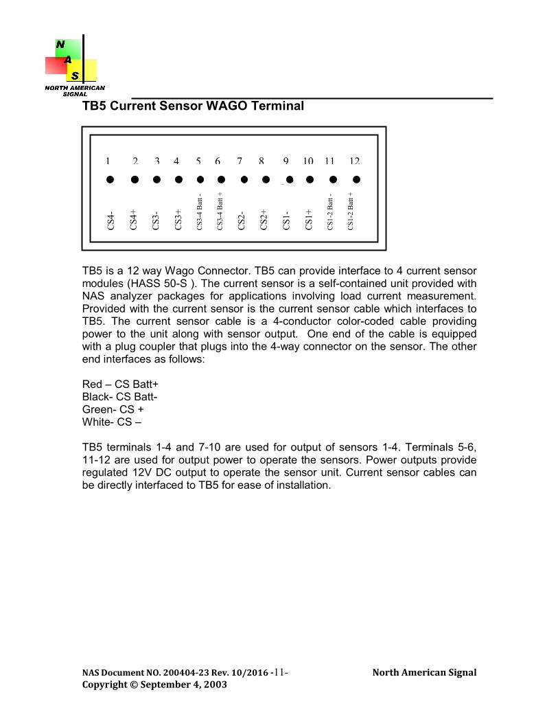
TB5 Current Sensor WAGO Terminal TB5 is a 12 way Wago Connector. TB5 can provide interface to 4 current sensor modules (HASS 50-S ). The current sensor is a self-contained unit provided with NAS analyzer packages for applications involving load current measurement. Provided with the current sensor is the current sensor cable which interfaces to TB5. The current sensor cable is a 4-conductor color-coded cable providing power to the unit along with sensor output. One end of the cable is equipped with a plug coupler that plugs into the 4-way connector on the sensor. The other end interfaces as follows: Red – CS Batt+ Black- CS Batt- Green- CS + White- CS – TB5 terminals 1-4 and 7-10 are used for output of sensors 1-4. Terminals 5-6, 11-12 are used for output power to operate the sensors. Power outputs provide regulated 12V DC output to operate the sensor unit. Current sensor cables can be directly interfaced to TB5 for ease of installation.
1 2 3 4 5 6 7 8 9 10 11 12
CS4
- C
S4+
CS3
- C
S3+
CS3
-4 B
att -
C
S3-4
Bat
t +
CS2
- C
S2+
CS1
- C
S1+
CS1
-2 B
att -
C
S1-2
Bat
t +
NAS Document NO. 200404-23 Rev. 10/2016 -12- North American Signal Copyright © September 4, 2003
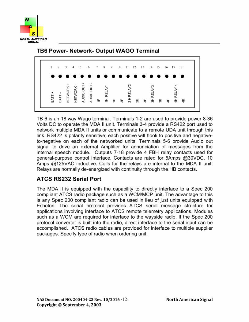
TB6 Power- Network- Output WAGO Terminal TB 6 is an 18 way Wago terminal. Terminals 1-2 are used to provide power 8-36 Volts DC to operate the MDA II unit. Terminals 3-4 provide a RS422 port used to network multiple MDA II units or communicate to a remote UDA unit through this link. RS422 is polarity sensitive; each positive will hook to positive and negative-to-negative on each of the networked units. Terminals 5-6 provide Audio out signal to drive an external Amplifier for annunciation of messages from the internal speech module. Outputs 7-18 provide 4 FBH relay contacts used for general-purpose control interface. Contacts are rated for 5Amps @30VDC, 10 Amps @125VAC inductive. Coils for the relays are internal to the MDA II unit. Relays are normally de-energized with continuity through the HB contacts.
ATCS RS232 Serial Port
The MDA II is equipped with the capability to directly interface to a Spec 200 compliant ATCS radio package such as a WCM/MCP unit. The advantage to this is any Spec 200 compliant radio can be used in lieu of just units equipped with Echelon. The serial protocol provides ATCS serial message structure for applications involving interface to ATCS remote telemetry applications. Modules such as a WCM are required for interface to the wayside radio. If the Spec 200 protocol converter is built into the radio, direct interface to the serial input can be accomplished. ATCS radio cables are provided for interface to multiple supplier packages. Specify type of radio when ordering unit.
BA
TT +
B
ATT
-
NE
TWO
RK
+
NE
TWO
RK
- A
UD
IO O
UT+
A
UD
IO O
UT
- 1F
1H
RE
LAY
1 1B
2F
2
H R
ELA
Y2
2B
3F
3H R
ELA
Y3
3B
4F
4H R
ELA
Y 4
4B
1 2 3 4 5 6 7 8 9 10 11 12 13 14 15 16 17 18

NAS Document NO. 200404-23 Rev. 10/2016 -13- North American Signal Copyright © September 4, 2003
RS232 Port The MDA II is equipped with a general-purpose DB9 RS232 pass through port used for direct interface to devices equipped with RS232 communication interface. Grade Crossing predictors, Interlocking Controllers, Processor based control equipment can be looked at through interface to this port. Depending on the type of telemetry packages in place, a virtual remote terminal session can be provided with this interface. External Radio RS232 Port The MDA II can be configured with virtually any type of telemetry package for transmission of wayside analysis events. The CalAmp Guardian 5 watt 9600-baud VHF radio modem (or T96SR, no longer available after 8/2011, the Guardian is the compatible replacement). The External DB9 Radio port is used to directly interface to the Serial Interface on these radios. Isolated power using internal DC-DC converters is provided on this port to provide for ground isolation necessary for wayside applications. It is not necessary to provide peripheral expensive power conditioning systems to operate these units. Simply Plug and Play. Maintenance Ports Serial The MDA II is equipped with a maintenance port for access to system data and configuration interface. Standard DB9 Serial port is provided for access. The DCE device requires a standard communications application such as HyperTerminal or ProComm Plus. Port is independent and can be used by multiple devices at the same time. Only one device can initiate commands for menu access or configuration data. 19200, n, 8, 1. Internal Compact Flash The MDA II is equipped with a standard compact flash socket to allow users to use compact flash medium for download of system events or reports. In addition, the module can be used for security access key for interface to the MDA II test algorithms. The MDA II comes complete with an 8GB standard module for operation.

NAS Document NO. 200404-23 Rev. 10/2016 -14- North American Signal Copyright © September 4, 2003
Peripheral Devices DTMF Radio The MDA II can be equipped with an internal DTMF module to provide remote control along with voice annunciation features using a standard 2-way radio. The radio will come preprogrammed from the factory with operating frequencies for the customers operation. A slot in the cover is provided to attach an external antenna to the structure. The antenna recommended is listed in the NAS Ordering Reference Table. External Modem VHF Radio The MDA II is equipped with an External Modem port, which allows connection of a standard modem interface. The port is configurable using the Configurator Application Program and can accommodate a host of different types of Serial telemetry devices. Battery supply can be provided through the serial connector to power an external interface. VHF/UHF radios such as the CalAmp Guardian Part No. 140-5016-500. This unit can be deployed in a Hub configuration whereby multiple field units communicate to a base location. The MDA II can also serve as a hub interface or communications controller for applications involving this type interface. External Audio Out The MDA II, if equipped with a DTMF radio with voice annunciation capabilities, can be used to drive an external PA speaker. A conventional Audio + Audio- is provided to interface to an amplified speaker device.

NAS Document NO. 200404-23 Rev. 10/2016 -15- North American Signal Copyright © September 4, 2003
Current Sensor Modules Current sensor modules are used to provide a current reading to an analog input. These devices are used to read load currents on external devices. A picture of the device appears below. Interface cables are provided with each sensor.
Red and Black from the connector cable are terminated on the Batt+ Batt- of TB5. GRN and WHT are assigned to sensor inputs as designated for each sensor on TB5. The HASS 50-S is provided with a 25’ current sensor cable, on the end of this cable you will find a short module with the resistor built in. The sensor is a Hall Effect current sensor, whereby the load cable being measured must pass through the sensor following the arrow to ground to provide an output from the sensor. For the HASS 50-S the wire must feed through one time in the direction of the arrow.
HASS 50-S

NAS Document NO. 200404-23 Rev. 10/2016 -16- North American Signal Copyright © September 4, 2003
MDA II Ordering Reference Information The Micro Data Analyzer can be equipped with optional internal DTMF telemetry control and a number of external telemetry options for remote data reporting. Ordering references for each system configuration are listed in the table below. Item Unit Catalog Ref No. Micro Data Analyzer II EA MDA 040601-00 Micro Data Analyzer II with DTMF- Specify Freq EA MDA 040601-00-
DTMF Current Sensor Unit with 25 foot Cable EA NAS-CS100-CBL-25 DTMF Antenna Kit w 17 foot cable EA NAS-DTMF-AK-10

NAS Document NO. 200404-23 Rev. 10/2016 -17- North American Signal Copyright © September 4, 2003
MDA II Software Configuration
MDA II Program File Structure The MDA II module software configuration structure operates using assembler file structure. The unit contains three operating programs for system operation. Boot Program This program is loaded during system production and is not user configurable. Executive Program This program operates the MDA II system. The program is factory loaded and will not require modification unless there is a system configuration change at which time a fully complied program will be furnished to you for field installation. The program can be loaded using a simple file transfer program such as Procomm or Hyperterminal. Directions for loading Executive Programs appear in the following subsections. Application Program The application program is used to provide location specific operation. This program file is created using the NAS windows based APPLICATION Configurator program, which can be provided to you for system configuration. This program is what transforms the MDA II from a standard recording system to an intelligent analysis device. Input/Output Mnemonics, Telemetry configuration, Function assignment, Alarm Exception configuration all of this is created using the Configurator. The application program file is loaded into the MDA II using a standard file transfer program such as ProComm or HyperTerminal. A default application file comes pre loaded for the MDA II module and allows the unit to operate as a recorder or standard control module. No application logic, Alarm features or customized I/O mnemonics are provided with the default program. Right out of the box the unit can be hooked up to Inputs and the system will provide event-recording functions.

NAS Document NO. 200404-23 Rev. 10/2016 -18- North American Signal Copyright © September 4, 2003
Loading Application and Executive Program Files Using a standard file transfer program such as ProComm, HyperTerminal or PC Anywhere can complete application and Executive program file transfers to the MDA II. It is required to have a functioning application on the PC used for file transfer prior to performing these procedures. Refer to instructions for these programs that specify how to perform a file upload. Application and Executive files can be uploaded to the MDA II by the following procedure. Interface to the Maintenance Terminal Serial port using a standard 9 pin serial cable with a PC equipped with a standard communication package such as Hyper-terminal or ProComm Plus. Port settings are Direct Connect, 19,200, n, 8, 1. Plugging the cable into the port will initiate a terminal session with the MDA II unit. Maintenance Terminal Password Upon customer request, units can be equipped with password protection to access terminal screens. If unit is equipped with this feature, plugging serial cable into serial maintenance port will prompt user for password. Default password for unit is NAS. Passwords can be changed using the configuration program. ENTER MAINTENANCE PASSWORD: NAS Entering password and pressing enter will place user into terminal session and Main Menu screen will appear as shown on the following pages.

NAS Document NO. 200404-23 Rev. 10/2016 -19- North American Signal Copyright © September 4, 2003
Crossing Analyzer Application Sample Screens are shown below 06/26/02 16:12:27 NAS MDA MAIN MENU BOOT: LD_MDA REV.1 EXECUTIVE: MDA_I REV.1 APPLICATION: SHOW (1) LOG MENU (2) MAINTENANCE MENU (3) CALIBRATE LAMPS (4) SET TIME AND DATE (5) RESET UDA (6) PALM MODE ON (7) LOG OFF (9) FRA INSPECTION (D)ISABLE FTP SEND (E)NABLE FTP SEND, CLEAR FTP COUNTER "ESC" FOR MENUS As noted in the menu, the program file names running in the MDA II are shown in the header of the Main Menu screen. Whenever a new file is loaded to the system, the name of the program file will appear in this header. To initiate a file load Type 2 from the menu, the following screen will appear: MAINTENANCE MENU (1) DIGITAL INPUTS (2) ANALOG VALUES (3) LAMP CURRENTS (4) PICK ROR (5) DROP ROR (6) ADJUST BATTERY ALARM VALUES (7) ADJUST LAMP CURRENT ALARM VALUES (8) LOAD FIRMWARE E(X)IT Pressing 8 will prompt user to load new firmware. Application or Executive can be loaded after the prompt.
Each of the program files that are loaded in the MDA II will appear in the main Menu
display

NAS Document NO. 200404-23 Rev. 10/2016 -20- North American Signal Copyright © September 4, 2003
Administration Password (Firmware Load) Upon customer request, units can be equipped with password protection for loading firmware. If unit is equipped with this feature, password prompt will appear on the screen as shown. Default password is NAS. Passwords can be changed in the Configurator Program. ENTER ADMINISTRATION PASSWORD: NAS PRESS (Y) TO LOAD FIRMWARE BEGIN YOUR UPLOAD Typing Y will erase the current program and prepare the MDA II module for a new file upload. When this message appears, transfer the program file using the file transfer selections from the terminal session that you are operating. The file transfer does not use any protocol such as xmodem or z modem, etc. Select None if asked for a transfer protocol. Instructions for using HyperTerminal Highlight Transfer from Main tool bar and select SEND TEXT FILE. A standard window file selection menu will be displayed. The programs use an .s19 extension. Select the file from the directory where stored and press enter. Files take a couple of minutes to load with HyperTerminal and no status bar is displayed unlike ProComm, so be patient. If successfully loaded, the following screen will appear: UPLOAD COMPLETED, CPU WILL RESET NOW Congratulations, you are now running the new version of Application or Executive program for the CPU for the crossing analysis system. Congratulations, you are now running the new version of Application or Executive program for the MDA II system. *For more detailed instructions or further assistance please call us or see our website for MDAII Loading PDF.

NAS Document NO. 200404-23 Rev. 10/2016 -21- North American Signal Copyright © September 4, 2003
Creating Application Program Files The Windows based Configurator Program is used to create and compile application program files for the Analyzer system. A copy of the program will be furnished to you with purchase of the Analyzer package. Using MS ACCESS as it’s engine, the program is very easy to use and create a customized location. The customer should determine who would be the administrator of this package for the creation of these files. A separate user’s manual is available per request to guide you through system set up.

NAS Document NO. 200404-23 Rev. 10/2016 -22- North American Signal Copyright © September 4, 2003
Cellular Radio Programming (Optional) Radios will come from the factory programmed with site-specific information. If module is shipped with a cellular unit, an Operational Manual for that device will be included along with this manual.
Data Radio Programming (Optional) Radios will come from the factory programmed with user operating channels. The Ritron DTX-PLUS II (narrow band) model radio used on the DTMF module is capable of external channel selection using Switch Pack 1 on the Unit. You can order a programming kit for the Ritron DTX-PLUS II if needed for reprogramming frequency in the field. The Guardian VHF radio modem is capable of operating half or full duplex. To set up the radio or modify the frequency, you will need a standard DB9-DB9 serial cable and download the software from www.calamp.com.

NAS Document NO. 200404-23 Rev. 10/2016 -23- North American Signal Copyright © September 4, 2003
System Installation and Set Up Initial site Set Up When design, module configuration and interface wiring to external circuitry are complete, the MDA II module can undergo operational testing for the programmed application. The system should be tested to insure the function it was designed to perform is operational. The MDA II can be used as a tool to perform these functions. User Friendly Smart Menus are available on all NAS products, which allow the user to access diagnostic and test information through the Maintenance Terminal Port. After installation of the Application file in the unit module, a few steps are necessary to complete site set up. If units are equipped with telemetry products such as the VHF Data Radio/Cellular modem or the DTMF controller, it is recommended that Antenna configuration be installed external to the location. Schematics showing typical installations are shown in the Appendix. Operational testing of these components should be conducted along with module testing. If unit is equipped with DTMF Controller module, set up operational testing should be in accordance with design parameters installed in the Application Program File. Verify that all Battery connections are the proper polarity in accordance with
details shown on Terminal board Configurations Turn on Power to the MDA II Analyzer Insure Power LED’s located above the on/off switch are illuminated Verify that module LED communication is operating in accordance with the
details outlined in the Hardware Description section for each module. To Verify Inputs and Outputs are operating correctly, it will be necessary to
interface to the Diagnostic Maintenance port on the CPU. Analyzer Alarm Criteria Crossing Application What makes the MDA II special is the ability to analyze device parameters based on user defined variables and generate operational alarms or exceptions dependent on the operational data. The objective with the system is to identify a potential problem prior to the problem becoming a critical alarm or safety issue. More importantly, we have built in a number of algorithms that weed out false alarms or exceptions generated due to normal maintenance or train operation.
NAS Document NO. 200404-23 Rev. 10/2016 -24- North American Signal Copyright © September 4, 2003
With the analyzers ability to monitor Detector Voltage output from a GCP (EZ voltage) or RX Voltage from a HXP unit, we can provide a level of analysis unparalleled by any recorder available in the marketplace today. With over 90 user programmable functions used by the system, identifying a problem before it becomes a safety issue is what the analyzer is all about: Event logs are prioritized as Log, Exception, or Alarm allowing maintenance personnel to be in full control of the event criticality involved in the operational condition. The versatility of the analyzer allows the user to use analog and digital inputs for appropriate functions. Analogs Inputs can also perform digital functions allowing full use of available inputs allocated to the system. User defined Programmable functions used by the system: A depicts analog function only
AD depicts function can be assigned to an analog or digital input.
(*) * Depicts number of separate functions typical analyzer will handle. Bold - Depicts user definable value, default setting shown.
Gate Operation AD (8): Movement Time Down – o Exception Record- Operation faster than 5 seconds or slower than
16 seconds. o Alarm Record- Gate not down 5 seconds prior to train occupying
the Island. (Exception switching moves when detector voltage is less than 1 volt).
Gate Operation AD (8): Movement Time Up:
o Exception Record – Operation Slower than 20 Seconds- o Alarm Record- Movement Time Up 60 seconds – GPX down no
train.
Gate Control Delay AD (4): Each Gate Control function can be assigned to individual gates
o Exception Record- Delay time is less than 2 seconds or greater than 8 seconds.
Battery Voltage A (6):
o Exception Record- Battery Voltage drops below defined level. o Alarm Record- Battery voltage drops 2 Volts below exception value
setting.

NAS Document NO. 200404-23 Rev. 10/2016 -25- North American Signal Copyright © September 4, 2003
Power Off AD (3):
o Exception Record – 20 minutes, o Alarm Record 4 hours continuous.
Warning Time Calculation AD (4):
o Alarm Record- Warning time less than 20 seconds for train move.
Switching Mode Voltage A (6): o Record- Train stops on the approach Detector Voltage is 1 volt or
less island is activated. This movement disables short warning time and gate movement time down less than 5 second. Used where frequent switching or station stops are occurring in the approach circuit.
Activation Time Exceeded AD (4):
o Alarm Record- Crossing down for more than 20 minutes
Activation Starts Exceeded AD (4): separate crossing control inputs o Exception Record- 5 false activations due to Island dropping or MD
dropping with no train move.
Flashing Lights Current Sensors A (8): Total Lamps, Alarm for Lamps Out Value
o Exception record- Lamps out greater than Alarm Level- o Alarm Record- Lamps out at defined threshold for each current
sensor.
Flash Rate A (8): o Exception Record- Flash Rate less than 35 or greater than 65
inclusive.
Maintenance Mode AD - Record- Unit is equipped with an external switch that enables voice annunciation feature to assist with system testing. Feature also disables alarm criteria on all devices listed above eliminating false alarms during system testing. Automated time out Feature Programmable setting.
FRA Electronic Inspection AD: Unit is equipped with an internal or external
input that prioritizes all data generated during the FRA testing process as an Inspection Record. Data captured can be transferred to an electronic test record locally or on the remote Host Monitoring Unit.
NAS Document NO. 200404-23 Rev. 10/2016 -26- North American Signal Copyright © September 4, 2003
DTMF Control Tones (8) D: - Record- Logs when DTMF tone is activated
for Remote Operate Relay and GP Control.
Detector Voltage A (6 Normal and standby detector track circuits): Record- Detector voltages from a predictor or motion sensor are recorded anytime a rate of change of 10% occurs in reference to the last recorded value.
Alarm Disable AD: Function can be assigned to an input to disable alarms
when activated. Typically used when DTMF Control is activated from on track Equipment to prevent alarms due to shunting of equipment.
Inspection Function AD: Function can be assigned to an input variable to
accommodate local inspections such as grounds, visual inspection providing a record log that the inspection was performed. Useful for Inspection and testing procedures for the Electronic Test Record.
Auxiliary Alarm AD: Alarm or Exceptions can be assigned to any input
device. Maintenance Log: The system generates an automated maintenance log at a programmed interval which takes a snapshot of important operating parameters such as last 5 warning times, Battery Voltages, Lamps Lit, Flash Rate, Detector Voltages. Log will be reported to the Host Monitoring System.
Maintenance and Diagnostic Menus
Terminal Interface Similar to loading application files, to access the MDA II menus a serial device such as a laptop or PDA is required to interface to the maintenance port on the CPU or ATCS modules. The port is a DB9 female serial port for interface. To access menus, the serial device will require a terminal interface program such as HyperTerminal or ProComm Plus. Settings for port interface are Direct Connect 19,200 baud N, 8,1. After launching terminal program plug serial cable into port and press Enter. The Main Menu will appear. The Menu selection procedures on the MDA II module are very simple to navigate through. By entering Text or Alpha Characters located in Parenthesis ( ), the menu selection will appear. Stepping back to the previous menus can always be accomplished by pressing the ESC key.

NAS Document NO. 200404-23 Rev. 10/2016 -27- North American Signal Copyright © September 4, 2003
Menus Recorder Application Maintenance Terminal Password Upon customer request, units can be equipped with password protection to access terminal screens. If unit is equipped with this feature, plugging serial cable into serial maintenance port will prompt user for password. Default password for unit is NAS. Passwords can be changed using the configuration program. ENTER MAINTENANCE PASSWORD: NAS Entering the password and pressing Enter will place user into terminal session, and the Main Menu screen appears. Main Menu After interfacing to the serial port on the CPU module, pressing Enter provides access to the Main Menu screen shown below. MAIN MENU BOOT: MBOOT10 EXECUTIVE: M2_EX39B I/O MODULE: M2_IO39A APPLICATION: MDA2 NAS LAB 590 12345678 FTP COUNT: 00 (1) LOG MENU (2) MAINTENANCE MENU (3) CALIBRATE LAMPS (4) SET TIME AND DATE (5) RESET UDA (6) PALM MODE ON (7) LOG OFF (9) FRA INSPECTION (D)ISABLE FTP SEND (E)NABLE FTP SEND, CLEAR FTP COUNTER "ESC" FOR MENUS Sample sessions for each Main Menu selection are shown in the following sections.

NAS Document NO. 200404-23 Rev. 10/2016 -28- North American Signal Copyright © September 4, 2003
(1) Log Menu
This Main Menu selection is used to retrieve stored alarms or system logs. LOG MENU (1) FIND EVENT BY DATE / HOUR (2) LAST 32 EXCEPTIONS / ALARMS (3) TAB DELIMITED OUTPUT ON (F)OWARD (B)ACK ctl (F)OWARD DUMP ctl (B)ACK DUMP (E)ND E(X)IT Entering 1 will query for a time and date to search for records; enter in format shown. ENTER SEARCH MONTH, DATE, YEAR, HOUR: MMDDYYHH 07/18/02 10 *** SEARCHING *** 07/18/2002 10:00:00 LOG RECORDER MAINTENANCE REPORT 07/18/2002 10:00:00 LOG CS1 NUMBER OF LAMPS LIT 00 07/18/2002 10:00:00 LOG CS1 FLASH RATE PER MINUTE 000 07/18/2002 10:00:00 LOG TK1 NRX DETECTOR VOLTAGE 00.00 07/18/2002 10:00:00 LOG CROSSING POWER OFF (min) 000 07/18/2002 10:00:00 LOG B12 VOLTAGE 00.00 07/18/2002 10:00:11 EXCEPTION CS1 FLASH RATE PER MINUTE 000 07/18/2002 10:00:11 ALARM CS1 NUMBER OF LAMPS OUT 04 07/18/2002 10:00:24 EXCEPTION CROSSING POWER OFF (min) 001 07/18/2002 10:00:25 LOG B12 VOLTAGE 00.00 07/18/2002 10:01:03 LOG RECORDER POWERED DOWN 07/18/2002 10:01:08 LOG RECORDER POWERED UP Logs starting with the query date will automatically be retrieved and displayed

NAS Document NO. 200404-23 Rev. 10/2016 -29- North American Signal Copyright © September 4, 2003
Entering 2 on Log Menu Selection will retrieve last 32 alarms or exceptions that occurred during system operations. 07/18/2002 10:01:52 ALARM CS1 NUMBER OF LAMPS OUT 04 07/18/2002 10:01:51 EXCEPTION CS1 FLASH RATE PER MINUTE 000 07/18/2002 10:00:24 EXCEPTION CROSSING POWER OFF (min) 001 07/18/2002 10:00:11 ALARM CS1 NUMBER OF LAMPS OUT 04 07/18/2002 10:00:11 EXCEPTION CS1 FLASH RATE PER MINUTE 000 07/18/2002 07:51:26 ALARM CROSSING POWER OFF (min) 002 07/18/2002 07:50:25 EXCEPTION CROSSING POWER OFF (min) 001 07/18/2002 07:50:11 ALARM CS1 NUMBER OF LAMPS OUT 04 07/18/2002 07:50:11 EXCEPTION CS1 FLASH RATE PER MINUTE 000 07/18/2002 07:49:24 EXCEPTION GATE CONTROL RELAY DELAY (sec) 000 07/18/2002 07:48:24 ALARM CS1 NUMBER OF LAMPS OUT 04 07/18/2002 07:48:24 EXCEPTION CS1 FLASH RATE PER MINUTE 000 07/18/2002 07:47:36 EXCEPTION GATE CONTROL RELAY DELAY (sec) 000 07/18/2002 07:46:54 EXCEPTION CROSSING POWER OFF (min) 001 07/18/2002 07:46:41 ALARM CS1 NUMBER OF LAMPS OUT 04 07/18/2002 07:46:41 EXCEPTION CS1 FLASH RATE PER MINUTE 000 Entering F and B from the Menus will take you forward or backward from the last displayed logs. Selecting this when the log menu is first displayed will retrieve the last records stored by the unit. Sixteen events at a time will be displayed. Ctl+B-Ctl+F: Entering these commands from the keyboard will provide continuous display of events backwards or forwards from the last displayed event. Toggling Ctl+B or F or pressing Esc can halt display. End (E) will take you to the end of the stored memory file displaying the most previous records. Start (S) will take you to the beginning of the stored data records.
NAS Document NO. 200404-23 Rev. 10/2016 -30- North American Signal Copyright © September 4, 2003
(2) Maintenance Menu This Main Menu selection displays status of events in real time. MAINTENANCE MENU (1) DIGITAL INPUTS (2) ANALOG VALUES (3) LAMP CURRENTS (4) PICK ROR (5) DROP ROR (6) ADJUST BATTERY ALARM VALUES (7) ADJUST LAMP CURRENT ALARM VALUES (8) LOAD FIRMWARE E(X)IT Selections are as follows: (1) Displays digital inputs that are currently on (high) Mnemonics of the input
will be displayed. (2) Analog Inputs - Displays Analog parameters that are on with voltage
value. (3) Display Lamps and Flash Rate

NAS Document NO. 200404-23 Rev. 10/2016 -31- North American Signal Copyright © September 4, 2003
Note: Lamps must be turned on. Used where Current Sensors are monitoring lamp voltages and flash rates on lamps. Display will show current on each current sensor and flash rate assigned to each digital or analog input as configured. INPUT AMPS CS1 10.0 CS2 8.5 CS3 13.2 CS4 4.1 SPARE 00.0 SPARE 00.0 SPARE 00.0 SPARE 00.0 INPUT F/R INPUT F/R FLASH RATE 1 45 FLASH RATE 2 48 SPARE 00 SPARE 00 SPARE 00 SPARE 00 SPARE 00 SPARE 00 SPARE 00 SPARE 00 SPARE 00 SPARE 00 SPARE 00 SPARE 00 (4) and (5) If remote operate relay is controlled by one of the relay outputs, selecting will energize and de-energize this output. Provides remote control of the site using a laptop or PDA device.

NAS Document NO. 200404-23 Rev. 10/2016 -32- North American Signal Copyright © September 4, 2003
(6) Adjust Battery Alarm Values (Administrative Password Required) This menu item allows the user to adjust battery alarm levels from the menu item. Battery alarm values are initially assigned using the configuration program. These programmed values will be stored in memory and can be recalled by entering P for Programmed Value. Programmed Value will appear in the display as shown below. Administrative Password must be entered prior to allow modification to parameters. NAME PROGRAMMED VALUE MODIFIED VALUE (0) BATT1 10.50 (1) BATT2 11.00 "ESC" TO EXIT OR NUMBER TO MODIFY: 0 (pressing 0 or 1 will prompt user for new value) Enter Administrative Password: NAS ENTER NEW VALUE (VV.VV), "P" FOR PROGRAMED VALUE, "A" TO ABORT 11.65 NAME PROGRAMMED VALUE MODIFIED VALUE (0) BATT1 11.65 (New Value will be displayed) (1) BATT2 11.00 "ESC" TO EXIT OR NUMBER TO MODIFY: 1 ENTER NEW VALUE (VV.VV), "P" FOR PROGRAMED VALUE, "A" TO ABORT 12.00 NAME PROGRAMMED VALUE MODIFIED VALUE (0) BATT1 11.65 (1) BATT2 12.00 "ESC" TO EXIT OR NUMBER TO MODIFY: 0 ENTER NEW VALUE (VV.VV), "P" FOR PROGRAMED VALUE, "A" TO ABORT “P” Entered will restore value to programmed value as displayed below NAME PROGRAMED VALUE MODIFIED VALUE (0) BATT1 10.50 (1) BATT2 12.00

NAS Document NO. 200404-23 Rev. 10/2016 -33- North American Signal Copyright © September 4, 2003
(7) Adjust Lamp Current Alarm Values (Administrative Password required) This menu item allows the user to adjust lamp current alarm levels from the menu item. Lamp current alarm values for each current sensor are initially assigned using the configuration program. These programmed values will be stored in memory and can be recalled by entering P for Programmed Value. Programmed Value will appear in the display as shown below when selection is entered. Administrative Password must be entered prior to allow modification to parameters. NAME PROGRAMMED VALUE MODIFIED VALUE (0) CS1 2.6 (1) CS2 1.0 (2) CS3 2.8 (3) CS4 2.8 "ESC" TO EXIT OR NUMBER TO MODIFY: 1 Enter Administrative Password: NAS ENTER NEW VALUE (A.A), "P" FOR PROGRAMMED VALUE, "A" TO ABORT 3.5 NAME PROGRAMED VALUE MODIFIED VALUE (0) CS1 2.6 (1) CS2 3.5 (2) CS3 2.8 (3) CS4 2.8 "ESC" TO EXIT OR NUMBER TO MODIFY: 0 ENTER NEW VALUE (A.A), "P" FOR PROGRAMED VALUE, "A" TO ABORT 2.5 NAME PROGRAMMED VALUE MODIFIED VALUE (0) CS1 2.5 (1) CS2 3.5 (2) CS3 2.8 (3) CS4 2.8

NAS Document NO. 200404-23 Rev. 10/2016 -34- North American Signal Copyright © September 4, 2003
"ESC" TO EXIT OR NUMBER TO MODIFY: 1 ENTER NEW VALUE (A.A), "P" FOR PROGRAMED VALUE, "A" TO ABORT P NAME PROGRAMMED VALUE MODIFIED VALUE (0) CS1 2.5 (1) CS2 1.0 (2) CS3 2.8 (3) CS4 2.8 (8) Load Firmware System will prompt user for Administrative Password prior to loading application or executive firmware. Enter Administrative Password: PRESS (Y) TO LOAD FIRMWARE BEGIN YOUR UPLOAD Refer to the Loading Application and Executive Programs on page 18 for instruction to upload new programs to the MDA II unit. (3) Lamp Calibration This Main Menu selection is used to perform lamp calibration where current sensors are used to monitor flashing lights. Calibration of lamps must be completed with AC power on and AC power off to operate correctly. Lights must be flashing to calibrate. Typing Y completes the set up. ARE THE LIGHTS FLASHING? (Y/N) Pressing Y will display current values to assigned sensors along with Flash Rates as shown below. INPUT AMPS CS1 10.0 CS2 8.5 CS3 13.2 CS4 4.1 SPARE 00.0 SPARE 00.0 SPARE 00.0 SPARE 00.0

NAS Document NO. 200404-23 Rev. 10/2016 -35- North American Signal Copyright © September 4, 2003
INPUT F/R INPUT F/R FLASH RATE 1 45 FLASH RATE 2 48 SPARE 00 SPARE 00 SPARE 00 SPARE 00 SPARE 00 SPARE 00 SPARE 00 SPARE 00 SPARE 00 SPARE 00 SPARE 00 SPARE 00 (4) Set Time and Date This Main Menu selection sets the time and date of the recorder. If the units are configured with a centralized monitoring system or access to web timer server via Internet interface, the recorder time will be synched from the central or the web timeserver. If not, time set is manual. Time resolution on events is to tenths of a second. ENTER NEW DATE AND TIME: MMDDYYHHMMSS.S 05/27/02 17:35:00.0 NEW TIME SET TO: 17:35:00 05/27/02 17:35:00 (5) Reset Initiating this command resets the analyzer module. The unit will go through a countdown during reset prior to the Main Menu displaying. Insure you wait for the countdown to finish prior to pressing Enter on the keyboard. (6) Palm Mode On/Off The analyzer has the ability to configure the screen size for display on a PDA unit. Entering 6 will toggle the screen size between 72 and 48 characters per line. (7) Log Off Entering 7 will end the terminal session. This will also log the user off if you are remotely connected through a modem.
NAS Document NO. 200404-23 Rev. 10/2016 -36- North American Signal Copyright © September 4, 2003
(9) FRA Inspection Mode The MDA II is equipped with an Inspection algorithm that collects logs for completion of FRA inspection records. This function can be assigned to an input for remote testing applications using the Configurator Program, but it is recommended to use Menu Selection (9) to complete the sequence. When the menus are enabled, the MDA II will be placed in an electronic inspection mode. The following menus will appear: USER ID: TTROVATO User enters ID select Y if correct N to re-enter. CORRECT (Y) (N) E(X)IT After User ID is entered correctly, Testing Interval will appear as shown below. (1) MONTHLY (2) QUARTERLY By selecting Number Interval will Echo as shown (3) ANNUAL MONTHLY CORRECT (Y) (N) After Interval is selected, Unit will enter Inspection Mode. When this occurs, all logs are captured to the log until FRA Mode is aborted, or Completed: FRA main Inspection Menu will appear FRA Inspection Menu Main Inspection Menu (0) PREEMPTION (1) GROUND (2) VISUAL (3) IJ-BONDS-TK.CON (4) CUT OUT CKT. (5) LAMP VOLTAGES (6) BELL (7) ADJUST (8) REPAIR (9) REPLACE (A)BORT FRA TEST (E)NTER COMMENT (64 CHARACTERS MAX) (C)OMPLETE E(X)IT

NAS Document NO. 200404-23 Rev. 10/2016 -37- North American Signal Copyright © September 4, 2003
nas LAB 590 12345678 SOUTHERN FL 1 1 RECORDER EXECUTIVE: M2_EX13 RECORDER APPLICATION: MDA2LAN2 03/14/06 05:54:08 LOG INSPECTION MODE ON 03/14/06 05:54:10 LOG TTROVATO EMPLOYEE ID 03/14/06 05:54:10 LOG MONTHLY INSPECTION ON 03/14/06 05:54:10 LOG CS1 NUMBER OF LAMPS LIT 08 03/14/06 05:54:10 LOG CS2 NUMBER OF LAMPS LIT 08 03/14/06 05:54:10 LOG CS3 NUMBER OF LAMPS LIT 10 03/14/06 05:54:10 LOG CS4 NUMBER OF LAMPS LIT 10 03/14/06 05:54:10 LOG CROSSING WARNING TIME (sec) 000 03/14/06 05:54:10 LOG CROSSING WARNING TIME (sec) 000 03/14/06 05:54:10 LOG CROSSING WARNING TIME (sec) 000 03/14/06 05:54:10 LOG CROSSING WARNING TIME (sec) 000 03/14/06 05:54:11 LOG CROSSING WARNING TIME (sec) 000 03/14/06 05:54:11 LOG CS1 LAMP CURRENT LOW (amps) 25.5 03/14/06 05:54:11 LOG CS2 LAMP CURRENT LOW (amps) 25.5 03/14/06 05:54:11 LOG CS3 LAMP CURRENT LOW (amps) 25.5 03/14/06 05:54:11 LOG CS4 LAMP CURRENT LOW (amps) 25.5 03/14/06 05:54:11 LOG FLASH RATE 4 FLASH RATE PER MINUTE 000 03/14/06 05:54:11 LOG FLASH RATE 4 FLASH RATE PER MINUTE 000 03/14/06 05:54:11 LOG BATT1 VOLTAGE 00.00 03/14/06 05:54:11 LOG BATT2 VOLTAGE 00.00 (0) PREEMPTION (1) GROUND (2) VISUAL (3) IJ-BONDS-TK.CON (4) CUT OUT CKT. (5) LAMP VOLTAGES (6) BELL (7) ADJUST (8) REPAIR (9) REPLACE (A)BORT FRA TEST (E)NTER COMMENT (64 CHARACTERS MAX) (C)OMPLETE E(X)IT The Inspection Menu above is used to manually enter inspections, repairs, adjustments, and replacements. Each entry will create an electronic record in the inspection log when manually selected. All events that occur while in FRA Inspection mode can be used to create the Electronic Inspection record manually or automatically if equipped with Telemetry and host monitoring. The MDA II has a smart algorithm built in that will automatically log Battery Voltages every ten

NAS Document NO. 200404-23 Rev. 10/2016 -38- North American Signal Copyright © September 4, 2003
minutes with a power off condition. Events such as Gate Movements, Gate Control Delay Time, Warning Times, Battery Voltages, and Power On and Off are all captured and logged by the MDA II unit. Alarms or Exceptions that are generated while in FRA mode are not reported if equipped until FRA mode is completed or aborted. When in FRA mode, other menus such as the Maintenance Menu can be accessed and used with menu entries. To return to the FRA menu, select 9 from the Main Menu on the MDA II. FRA Mode can be completed or Aborted by selecting A or C from the Inspection Menu (0) PREEMPTION (1) GROUND (2) VISUAL (3) IJ-BONDS-TK.CON (4) CUT OUT CKT. (5) LAMP VOLTAGES (6) BELL (7) ADJUST (8) REPAIR (9) REPLACE (A)BORT FRA TEST (E)NTER COMMENT (64 CHARACTERS MAX) (C)OMPLETE E(X)IT Any manual entry that is made will ask for a Y or N confirmation and echo the results on the screen as shown below: (0 Entered) 02/18/03 13:02:42 LOG PREEMPTION INSPECTION PASSED

NAS Document NO. 200404-23 Rev. 10/2016 -39- North American Signal Copyright © September 4, 2003
When 7, 8, or 9 are entered from the main Inspection Menu, the following sub menu will appear: Device Menu (7 Entered) ADJUST (0) LAMP (1) BELL (2) BATTERY (3) GATE ARM (4) MECHANISM (5) TIMING DEVICE (6) IJ-BONDS-TRACK CON (7) CUT OUT CKT. E(X)IT ADJUST BATTERY CORRECT (Y) (N) Make entries by selecting the appropriate numbers for the device. Entries will need to be confirmed prior to the log being excepted as shown above. 02/18/03 13:03:19 LOG ADJUST BATTERY (0) PREEMPTION (1) GROUND (2) VISUAL (3) IJ-BONDS-TK.CON (4) CUT OUT CKT. (5) LAMP VOLTAGES (6) BELL (7) ADJUST (8) REPAIR (9) REPLACE (A)BORT FRA TEST (E)NTER COMMENT (64 CHARACTERS MAX) (C)OMPLETE E(X)IT (E) Enter Comment MDAII is equipped with the ability to enter a text comment up to 64 characters in length. Pressing E provides the user with a prompt screen. Comments are placed in the system memory log. Backspace capability is provided for entry mistakes but once entered comments cannot be modified in system memory.

NAS Document NO. 200404-23 Rev. 10/2016 -40- North American Signal Copyright © September 4, 2003
PRESS "ENTER" WHEN FINISHED CLEANED LIGHTS, ADJUSTED GATE ARM. NO GROUNDS FOUND Memory Log showing manual comments entered. Entries are time stamped when entered. 03/14/06 05:55:56 LOG INSPECTION MODE OFF 03/14/06 05:55:45 LOG COMMENT LEFT CROSSING WORKING WATCHED TWO TRAINS BY 03/14/06 05:55:12 LOG COMMENT CLEANED LIGHTS, ADJUSTED GATE ARM. NO GROUNDS FOUND When all manual or automatic entries are complete, complete the log by typing C from the main Inspection Menu. Pressing C on the FRA menu will echo the manual tests that were performed for verification. Once verified, the MDA II will exit to the Log Menu Screen as shown below: TESTS PERFORMED C Pressed PREEMPTION GROUND VISUAL IJ-BONDS-TK.CON CUT OUT CKT. LAMP VOLTAGES BELL CORRECT (Y) (N) Enter (Y) to exit inspection mode and display the Log Menu as shown below. Exit the Log Menu by pressing (X). LOG MENU (1) FIND EVENT BY DATE / HOUR (2) LAST 32 EXCEPTIONS / ALARMS (3) TAB DELIMITED OUTPUT ON (F)OWARD (B)ACK ctl (F)OWARD DUMP ctl (B)ACK DUMP (E)ND E(X)IT 03/14/06 05:55:56 LOG INSPECTION MODE OFF

NAS Document NO. 200404-23 Rev. 10/2016 -41- North American Signal Copyright © September 4, 2003
Inspection Logs can be reviewed by selecting B, which displays logs back in time from the last recorded event. This is useful if the logs are being captured for archive using a terminal program for populating a test record. If the unit is equipped with telemetry and host monitoring, the MDA II will automatically forward the log to the server for form population. (D) Disable FTP Send Units configured with central reporting or email reporting capability utilize FTP protocol for log transmission. If it is necessary to disable this feature, (D) is pressed from the Main Menu. FTP Disabled Message will appear, confirming entry. (E) Enable FTP Send, Clear FTP Counter If FTP is disabled using above disable command, enable by pressing (E) from the Main Menu. Units equipped with cellular telemetry devices utilize a counter (12 transmissions per 24 hour period) to limit transmission activity. Enable feature will reset the counter to zero. FTP enabled message will appear confirming menu entry.

NAS Document NO. 200404-23 Rev. 10/2016 -42- North American Signal Copyright © September 4, 2003
Maintenance Mode Switch The MDA II is equipped with a Maintenance Mode switch that will disable alarms generated by the system when the switch is in the On position. This feature is useful when tests are being performed on the location and will provide a maintenance log of the site when the switch is in the On position. The switch can be configured to time out if programmed in the Configurator settings. In addition, if unit is equipped with DTMF with Voice annunciation, enabling maintenance mode will announce activated/deactivate messages over the radio for confirmation during system testing. This is especially helpful during annual shunt tests on crossings where site distance is limited. The MDA II can be programmed with custom messages providing defect detection, drawbridge status or numerous other messages for device confirmation. Typical Maintenance Mode Log is displayed below: 07/18/2002 10:03:49 LOG MAINTENANCE MODE ON SIGNAL RSSI SHOW 41590E RECORDER EXECUTIVE: MICRO REV 5I RECORDER APPLICATION: SHOW 07/18/2002 10:03:49 LOG CROSSING WARNING TIME (sec) 000 07/18/2002 10:03:50 LOG CROSSING WARNING TIME (sec) 000 07/18/2002 10:03:50 LOG CROSSING WARNING TIME (sec) 060 07/18/2002 10:03:50 LOG CROSSING WARNING TIME (sec) 060 07/18/2002 10:03:50 LOG CROSSING WARNING TIME (sec) 060 07/18/2002 10:03:50 LOG CS1 NUMBER OF LAMPS LIT 00 07/18/2002 10:03:50 LOG CS1 FLASH RATE PER MINUTE 000 07/18/2002 10:03:50 LOG TK1 NRX DETECTOR VOLTAGE 00.00 07/18/2002 10:03:50 LOG CROSSING POWER OFF (min) 002 07/18/2002 10:03:50 LOG B12 VOLTAGE 00.00 07/18/2002 10:03:53 LOG MAINTENANCE MODE OFF

NAS Document NO. 200404-23 Rev. 10/2016 -43- North American Signal Copyright © September 4, 2003
LED Indicators The MDA II is equipped with an LED indicator panel used for quick indication of input status. Battery monitor LED indicators, Analog Input indicators, and Digital Input indicators are provided and function based on the following criteria. Battery Monitor Indicators:
LED illuminates solid if the battery is greater than exception value setting used by the analysis criteria.
LED flashes continuous if battery is between Alarm value and exception value indicating a low battery condition.
LED is dark if no battery voltage is present on the designated input. Analog Input Indicators
LED illuminates steady if voltage above 5 volts is present on the input. Digital Input Indicators
LED illuminates steady if voltage above 5 volts is present on the input. Status Indicator
LED flashes at one-second interval indicating normal operation of the MDA II unit. LED illuminates continuously when unit is being loaded with Executive or Application program. LED extinguished indicates processor fault.
Auxiliary Indicators The MDA II is equipped with 3 auxiliary indicator LED indicators that can be programmed to monitor the following functions:
Carrier Detect – Units equipped with Telemetry options. Aux 1- User defined Aux 2- User defined.

NAS Document NO. 200404-23 Rev. 10/2016 -44- North American Signal Copyright © September 4, 2003
Maintenance and Troubleshooting The MDA II system is a robust hardware package designed to operate in the harshest environments. The module has onboard process control and visual LED indicators. Figuring out what to fix if it is broke is as straight forward as using the Maintenance Menus. At North American Signal Systems, we try very hard to keep things simple, which includes diagnosing a problem with the unit if it is not functioning correctly. As with any troubleshooting procedure, the first order of business is to assess what the reported problems are and eliminate potential causes. Visual inspection of the LED indicators on the chassis is a quick easy way to determine if the failure is hardware related. Troubleshooting Checklist
1. Chassis power lights not illuminated: Check input voltage on TB6 to determine if between 9-36 volts DC. Possible Cause – DC-DC Converter failure on motherboard, low voltage. Electronic Fuse Reset
2. Health LED not flashing at one and one half second rate on module:
Possible processor failure. Insure power is within specification.
3. Input or Output not functioning: Access Maintenance and Diagnostic Menus using portable serial device. Check connections and voltage on appropriate terminal on WAGO. Inputs are also equipped with LED indicator. If voltage is present, LED will be illuminated. If present, verify I/O indication appears on DIGITAL or ANALOG Input status screens.
4. Unit not communicating with Central office: Inspect antenna connections
and radio/modem LED indicators to determine if module is operational.
5. DTMF Controller not operational: Check status of LED indicators. Check antenna connections.
6. Unit not storing data: Verify logs can be retrieved from LOG MENU on
Maintenance and Diagnostic screens.

NAS Document NO. 200404-23 Rev. 10/2016 -45- North American Signal Copyright © September 4, 2003
Terms and Conditions of Sale General Our sale to you will be solely upon the terms and conditions set forth herein. They supersede and reject any conflicting terms and conditions of yours. Exceptions to any of our terms and conditions must be contained in a written or typed statement received from you. We shall not be deemed to have waived any of our terms and conditions or to have assented to any modification or alteration of such terms and conditions unless such waiver or assent is in writing and signed by an authorized officer. Prices Unless otherwise noted on the face thereof prices are net F.O.B our factory and firm for thirty (30) days. The amount of any applicable present or future tax upon the production, sale, shipment or use of goods ordered or sold will be added to billing unless you provide us with an appropriate exemption certificate. Warranty North American Signal Systems (NAS) warrants it products and systems against defects in material and workmanship for a period of One (1) Year from date of shipment. Sellers entire warranty obligation is limited to repairing or replacing any equipment which is returned within the warranty period and which the seller finds to be so defective. The integrity of NAS products and systems cannot be finally checked until all devices and circuits are connected to form a complete system or an effective portion thereof. Once accepted NAS’s warranty will be limited to parts that have been fully paid for. Return of equipment to Seller is at Buyers risk, and expense. Equipment returned to seller must be clearly identified and instructions must be furnished for reshipment to Buyer of the repaired or replaced device. Equipment will be returned to the NAS plant of original manufacture. Adjustments will not be allowed for products or components, which have been subject to abuse, alteration, improper handling or installation, or which have not been operated in accordance with the seller’s instructions. Cancellation of Orders A cancellation charge will be established on a percentage of completion basis. Restocking The seller on equipment returned to NAS for credit/or exchange will charge a restocking fee of 15%.

NAS Document NO. 200404-23 Rev. 10/2016 -46- North American Signal Copyright © September 4, 2003
Credit and Payment Unless otherwise noted terms are net 30 days. We may decline to deliver except for cash, or stop goods in transit, whenever for any reason doubt as to your financial responsibility develops. Pro rata payments shall become due with partial shipments. Where you are responsible for delay in shipment of any goods, the date of completion of goods may be treated as the shipment date for purposes of payment. On late payments the contract price shall be increased by 1 ½ percent per month on the unpaid balance but not to exceed the maximum permitted by law. Out of Warranty NAS will repair or replace equipment that is termed out of warranty under the following terms: The customer shall return equipment to NAS at customer’s expense. When the equipment is repaired and returned customer shall be invoiced for the equipment based on total cost of labor and materials used for repair, test and inspection. If it is determined by NAS that the repair cost will exceed 50% of the cost of new NAS will notify the customer prior to the repair being made for direction. Shipping Unless you specify otherwise, goods will be boxed or crated, as we deem proper for protection against normal handling. Routing and manner of shipment will be at our discretion and may be insured at your expense. Delivery of goods to the initial carrier will constitute delivery to you and all goods will be shipped at your risk. A claim for loss or damage in transit must be entered with the carrier and prosecuted by you. Proprietary Data Neither you nor any other person shall have any right to or have control over any engineering or production prints, drawings, or technical data which we in our sole discretion may consider proprietary to ourselves. Software Terms The following terms apply to products or systems that contain software. Subject to the terms and conditions hereof NAS grants you a nonexclusive
nontransferable license to use the software at the designated site listed hereof. This license extends wholly to your internal use of the software. The software shall be used only on the platform assigned.
If the platform is a single personal computer the software may be used by a single user on a single PC system
If the platform is a local area network the software may be used only on a single local area network at the designated site and in accordance with the number of users designated in the order for the system or as licenses permit.
If the platform is an embedded device or system the software may only be used for that single embedded device or system.

NAS Document NO. 200404-23 Rev. 10/2016 -47- North American Signal Copyright © September 4, 2003
Except with regard to embedded software you may copy the software on the
platform identified and make a backup copy of the software for archival purposes. Except for the license to use the software as expressly set forth in this agreement
all rights, titles and interest in the software shall be retained by NAS. You do not own any copies of the software or any portion thereof. Ownership of the software is retained by NAS. You will not or allow any third party to create a derivative of the work or modify any of the software without the approval of NAS. You will not allow any third party to reverse assemble, decompile, or otherwise reverse engineer all or any portion of the any product or system produced by NAS.
North American Signal Systems LLC Sales and Service Office 605 NW 53rd Ave. Suite A-17 Gainesville, FL 32609 Phone (352)376-8341 or (800) 201-5566 Website address www.nasignal.com Email [email protected]

NAS Document NO. 200404-23 Rev. 10/2016 -48- North American Signal Copyright © September 4, 2003
Appendix
Typical Circuits Micro Data Analyzer II Crossing Application


1 2 3 4 Ch #O O O O 8CL O O O 7O CL O O 6CL CL O O 5O O CL O 4CL O CL O 3O CL CL O 2CL CL CL O 1
DIP Switch 1
MDA II DTMF Channel Dipswitch Settings