Embed Size (px)
Citation preview


Acquisition modulesCan up to 16 User Slots
90° Rotation fixation plate Status LED line
Independent for each module
Power supply ModuleController ModuleWith Optional SSD Cartridge
Overview
The NanoX acquisition system is an efficient data concentrator andrecorder, with an ultra-compact design, and an ease of changingacquisition modules. The NanoX provide modularity and permit toplug/stack until sixteen data acquisition modules by unit. A unit isconstituted by a CPU/Controller module with a optional recordingcapacity (from 32GB to 2TB) and a smart power supply module. TheNanoX is a data acquisition concentrator completed with highspeed (1Gbps) recording and transmitting system combined inthe same device, with this device you can make all in one modularand compact solution where other solutions require two or threeseparate units.
Main Advantages Lightweight and small footprint unit. Fully Flexible Acquisition module/Chassis dimension. High speed recording system (1Gbps) with adapted controller. High recording capacity (Can up to 2TB) with adapted controller. Real time Data Streaming in DTMUX / IRIG 106 Chapter 10 / IENA formats Patented Xchange® Module Technology. Record and Replay function available. Transmitter (TX) module available (5 to 20Watts) Master/slave(s) Ethernet or Wi-fi Architecture available. Can be configured from one acquisition module to sixteen (16). Integrate Battery module for standalone/backup application. Integrate module status led for easy Diagnostic. Easy fixation on each side with 90° rotation support integrate. IRIG 106 Chapter 10 compliant (Recording option)

Controllers modules
Status LED (Green/Yellow or red)
GPS/ IRIG Status LED
Removable fixation plate with 90° rotation axis. To fix unit in each position
Communication/Maintenance connectorEthernet/RS-232/ IRIG B …
Module Frame fixation screws
Extraction Module screws
SMA Connector for GPS Antenna
Power presence Status LED (Blue)
The NanoX Controllers are available in four differentversion following your need, this one can integrate onlysome basic functionalities or integrate transmissionand recording functionalities to transform your dataacquisition system to a real and powerful datarecorder.
Three mains controllers configurations:[CPU-N-NX] Network capacity (For Master/Satellite(s) system).[CPU-NR-NX] Network & Recording capacity.[CPU-NT-NX] Network & IRIG 106, chapter 4 capacity.
Premium configuration:[CPU-NRT-NX] Network, Recording and IRIG 106 chapter 4 capacity.
CPU-N-NX presented here
CPU-N-NX Module OverviewNetwork capacity (For Master/Satellite(s) system).

Controllers modules
Dimensions are in “mm”CPU-N-NX Module Dimensions
Cooler heatsink+ 5mm 3x M5 fixation
*
**
*

Controllers modules Status LED (Green/Yellow or red)
GPS/ IRIG Status LED
Removable fixation plate with 90° rotation axis. To fix unit in each position
PCM Outputs connector2 independents channels
Module Frame fixation screws
Extraction Module screws
SMA Connector for GPS Antenna
Power presence Status LED (Blue)
CPU-NT-NX presented here
Communication/MaintenanceEthernet/RS-232/ IRIG B …
CPU-NT-NX Module OverviewNetwork & IRIG 106 chapter 4 capacity
Number of channelsTwo completely independentCompliant with IRIG 106 chapter- 4(PCM Class I & Class II) Specifications
Bit RateUp to 20Mbps better than 0.1% of specified rate.
Words/major FrameCompliant with IRIG 106 chapter- 4(PCM Class I & Class II) Specifications
Frames/minor FrameAs per IRIG 106 chapter- 4 (PCM Class I & Class II)
Sub Frame SynchronizationBy an incrementing Sub Frame identification (ID) word located anywhere within the minor frame. Provision to support URS & FCC
Sub-Frame size for each streamAs per IRIG 106 chapter- 4 (PCM Class I & Class II)
Pre-Modulation FilterBessel Filter selectable by software for the PCM n°2 1.25 MHz; 2.5 MHz; 5MHz; 10 MHz; 20 MHz; Bypass
Output codes2 PCM can be generated totally independent.Should support multiple programmable PCM data codes like NRZ-L, RNRZ-L, Bi-Phase-L/M
Output levelsFor the PCM1 TTL or RS422For the PCM2 TTL and Analog output with prefilter
Time reference From start of short or long frame with a resolution of better than one millisecond.

Controllers modules
Dimensions are in “mm”CPU-NT-NX Module Dimensions
Cooler heatsink+ 5mm 3x M5 fixation
*
**
*

Controllers modules
Status LED (Green/Yellow or red)
GPS/ IRIG Status LED
Removable fixation plate with 90° rotation axis. To fix unit in each position
PCM Outputs connector2 independents channels
Module Frame fixation screws
Extraction Module screws
SMA Connector for GPS Antenna
Power presence Status LED (Blue)
CPU-NRT-NX presented here
Communication/MaintenanceEthernet/RS-232/ IRIG B …
Premium CPU-NRT-NX Module OverviewNetwork, IRIG106 chapter 4 and Recording capacity
SSD Media cartridgeWith Extraction Handles

Features/Utility channels Audio input Irig B Time input GPS input (Time, Position…) Support IEEE 1588 Time v2 Discrete; ON/OFF and ON/OFF record Tricolor status outputs LED CPU, IRIG B, GPS status LED
RS 232 Communication Port for configuration Port for maintenance
Gigabit Ethernet Configuration/Control/Status/Download (from SSD) Real time transmitting for Real time visualization Network link with NanoX Satellites units PTP v2 Grandmaster Clock (option)
Wi-Fi 802.11g [OPTION] Configuration/Status/Download (from SSD) Network link with NanoX Satellites units Real time transmitting (To master Unit/ To decom software).
Discrete used to the NanoX functioning Discrete; ON/OFF and ON/OFF record Tricolor outputs LED Outputs: 2 cathodes and anode for operating green, orange, red. Intensity outputs for LED: 20 mA max.
Audio channel Input: 1 volt efficient. Sample frequency 31.25KHz Band pass: 0 to 14.7KHz Input impedance: 1 MΩ
Input Connector MICRO D (MIL-DTL-83513) for data Input/output SMA for GPS input
Recoding CapacityFrom 32GB to 2TBAvailable with CPU-NR-NX or CPU-NRT-NX only.
Ethernet Data Streaming DTMUX Format (By default) IRIG 106 Chapter 10 (Option) IENA (Option)
Time stamping/Synchronization Internal Time/IRIG B Time Time accuracy 1 µsec GPS Time IEEE 1588 (PTP v2) –Precision Time Protocol Time Offset programmable
Irig B channel Input: Sinus 1000 Hz, modulation level 1/3- 3/3. Output IRIG B time generation (1pps TTL). Modulation: 8Volts P to P max. To 500mVolts P to P min. Input Impedance greater than 10 KΩ Loss of the Irig B, time continuous to progress on internal base time Second, minutes, Hours and days.
GPS Function SMA independent input. Second, minutes, Hours and days (UTC). GPS data GPRMC format (Latitude, Longitude, Ground speed) Satellite acquisition less than 50 Seconds (Clear Sky) Output IRIG B time generation from GPS (1pps TTL). NMEA output at a rate of 1Hz Compatible with GPS Patch Antenna
Internal Sensors Temperature sensor / Pressure sensor / Humidity sensor
Master/Slave(s) link By Gigabit Ethernet (GbE) with IEEE 1588 Time (PTP v2) By Wi-Fi 802.11g [OPTION]
Controllers modules

Controllers modules
Optional Memory cartridgeThe unit can be also equipped with removable Solid-State Disk (SSD), available from 32GB to 2TB capacity.This Memory unit is rugged and full qualified for harshenvironment. SSD cartridge can be easily removed fromunit and connected to a Windows based computer withUSB 3.0 cable (Supplied).
P/N SSDXX-DE-QE-DP-NX*See below for part number composition
Handle
Rugged ConnectorFor easy plug on computer(SATA/USB 3.0 Cable supplied)
CapacityXX Capacity in Gigabytes (GB)32 / 64 / 128 / 256 / 512 / 1024 / 2048Sequential R/W (MB/sec, max.)90/90 (720Mbps)Max. Power consumption2.8 W (5Vx560mA)Extra DRAM BufferSupportedATA SecuritySupported
Vibration20G @7~2000HzShock1500G @0.5ms
Operation Temperature-40°C~+85°CStorage Temperature-55°C~+95°C Environmental standard MIL STD 810FMIL STD 461E
Replay On any Windows desktop (Seven or higher) with USB 2.0 or 3.0 input*SecurityPassword/ Encryption/Auto destruction can be available in option DE or none: 256bits AES Encryptions QE or none: Quick Erase DP or none: Physical Auto Destruction
Physique MTBF3 million hours
Available with CPU-NR-NX and CPU-NRT-NX

Power Supply module
[POWER-NX] moduleThe power supply module is constituted by two electrical circuitsand is conform to MIL-STD-704F, one circuit DC-DC Convertercard, and another one is Ultra capacitor circuit who protectNanoX installation from power interruption about 100milliseconds. There is no battery and therefore no preventivemaintenance for power down protection. These modules are alsoable to be powered by battery if aircraft power is not available.
Can support 16 different user modules. Until 130 Watts of power distribution. Compliant MIL-STD-704F standard. Powerful Ultra-capacitor to prevent power cut. MICRO D (MIL-DTL-83513) connector. Can be Extended with Battery module
Module ConnectorType MICRO D (MIL-DLT-83513)
Power presence Status LED
Removable fixation plate with 90° rotation axis. To fix unit in each positionModule Frame
fixation screws
MIL-STD-704F qualified, this module assures over voltage protection andpermit to protect and assure data safety during acquisition or recording incase of power failure. There is no battery and therefore no preventivemaintenance, for power down protection. These modules are also able tobe powered by battery if aircraft power is not available.
Temperature Management: Power supply module is also the seat of asmart and powerful Temperature control processor who permit theprotection of all unit in case of aggressive temperature environment, thisone monitors the temperature of each module and operate heating orcooling process following the environment encountered.

Power Supply module
Dimensions are in “mm”Power supply module Dimensions * With cooler heatsink

TechnicalInput ConnectorsMICRO D (MIL-DLT-83513)& SMA (For GPS Antenna)
Mounting90° Rotating support plate integrate.
Power supply28Volts DC (16 to 36V) MIL STD704 E Consumption: 12 Watts nominal (Controller& Power supply modules) until 130 Watts following configuration. Ultra-capacitor "to preserve recorder of power cuts (power interruption ≈100ms)
GroundingElectronics electrically isolated of the primary 28 Volts supply. GND electronics is also isolated of the NanoX external box.
WeightAbout 1.8 Kg (2 user-slots) About 2.2 Kg (4 user-slots) About 2.6 Kg (8 user-slots) About 3.0 Kg (12 user-slots) About 3.4 Kg (16 user-slots)
Cooling#
Passive convection
Position of useAll positions
MTBF> 30 000 hours MTTR< 1 minute (With spare module)
Transport Delivered with a transport suitcase equippedto receive the NanoX and accessories.
*Depth is increased of 18 mm with CPU module whoinclude recording capacity on SSD.
*Depth is increased of 16 mm with CPU module whoinclude IRIG 106 Chapter 4 capacity.
*Depth is increased of 16 mm with CPU module whoinclude Wi-Fi Network capacity option.
*Depth is increased of 80 mm with Power Supply whoinclude one additional Battery power supply module(Until 3 modules possible 3x80mm)
*Depth is increased of 24 mm with cooler heatsink(recommended for configuration use excitation voltage, video or more than 6 user module)
User-slot(s) Depth* width Height1 93 85 1002 109 85 1003 125 85 1004 141 85 1005 157 85 1006 173 85 1007 189 85 1008 205 85 1009 221 85 100
10 237 85 10011 253 85 10012 269 85 10013 285 85 10014 301 85 10015 317 85 10016 333 85 100
Size in “mm”

Environmental
Vibration MIL-STD-810G method 514.4 0.04 g² of 5 to 2000 Hz,1 hour per axis (3 axis)
Linear AccelerationMIL STD 810F, 15g for one minute in six directions.
Shocks MIL-STD-810F method 516.5/516.3100g, 11ms (6 axis) in functioning
Operating Temperature- 40°C to + 71°C. MIL-STD-810G method 502.5 procedure IIMIL-STD-810G method 501.5 procedure II
Extreme of temperature (Short period)- 55° C to 85°C [Short period no destructive] Test MIL STD 810FExtreme temperature cannot guarantee data integrity
Humidity in use5% to 95 % without condensationMIL STD 810F
Electromagnetic compatibility (EMI)MIL STD 461 Rev. G (2015)CE101 Power leads 30Hz to 10KHzCE102 Power leads 10KHz to 10MHZRE101 Magnetic field 30Hz to 100KHzRE102 Electric field 10KHz to 18GHz
Altitude and decompressionMin: -1500 feet, max: 60,000 feetWith 12.000 feet/minute (420Kpa/minute), MIL STD 810G.
Altitude max. StorageNo limit
Storage temperature- 55°C to + 90°C
Humidity in storage5% to 95 % without condensationMIL-STD-810G method 507.4
Aircraft Electrical Power CharacteristicsMIL-STD-704 Rev. F (2004)Prevent power down < 60 milliseconds

User module
One user module is constituted of two parts, firstly frame receiver module part who compose unitchassis and secondly the acquisition card part. The acquisition card part can be removed easily fromthe chassis module receiver part. With Xchange® Technology you can fit your frame dimensionand acquisition modules exactly like you want. It's not more necessary to uninstall unit from aircraftwhen you want to change or remove a module
Acquisition Module frame receiver
Integrated heatsink
Module Frame fixation screws
Status LED Module ConnectorsType MICRO D (MIL-DLT-83513)
Acquisition module fixation Screw
Linear Backplane connector

User module
Xchange® patented Technology, has been study and developed hand to handwith end users, to give the maximum of flexibility and growth capacity to asystem. NanoX system is fully flexible that mean each acquisition module can bereplaced by another one. System can be combined with different controllersmodules and acquisition modules who can be easily removed from their moduleframe receiver. Each module frame receiver are equipped with linear backplaneconnector who permit a connection with each other (until 16). That mean Mainframe of your unit is totally flexible but you have also the flexibility to put/removeor change Acquisition module where you want.
A big advantage also is the maintenance cost; with this kind of system if something goes wrong you can identify and replace quickly the problematic part of system.
In fact, NanoX system is assembly of different part who work together, and the assembly will make you think to a famous construction toy of your childhood.
Each Acquisition module can be extract and replaced easily
Linear Backplane connector

User module
Acquisition/Replay cards DimensionsDimensions are in “mm”

User module
Acquisition/Replay module with frame receiverDimensions are in “mm”
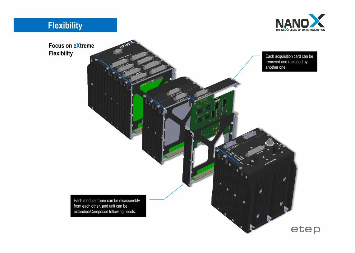
Flexibility
Focus on eXtremeFlexibility .
Each module frame can be disassembly from each other, and unit can be extended/Composed following needs.
Each acquisition card can be removed and replaced by another one

Analog/Sensors Modules
Example of a Part number: GAUGE-8-250-4-FB-NX
*Dynamic are programmable by software:For example, ±10V, ±1V, ±100mV, ±10mV
QB (Quarter Bridge)FB (Full/Half Bridge)
RP Record & Replay function available following Green indication
Modules can be tailored following your special needs, Hybrid modules are available for high integration application
Reference Option Device
DESIGNATION INPUTS Max Sample Rate (KHZ)
Max Dynamic (± Volts) *
Bridge Completion
RECORD & REPLAY NanoX
Single/Differential Ended Voltage VOLT 4 8 16 31 250 4 10 RP NX Accelerometer (ICP Sensors) ICP 4 8 12 31 250 4 10 RP NX Thermocouple (J, K, W, T, E) THERMO 4 8 16 31 250 4 10 RP NX Thermistor (PT100) THERMI 4 8 16 31 250 4 10 RP NX Pressure PRESS 4 8 31 250 4 10 RP NX Strain gauges GAUGE 4 8 12 31 250 4 10 FB QB RP NX Bridge signal (Piezoresistive) BRIDGE 4 8 12 31 250 4 10 FB QB RP NX Charge amplifier (Piezo) PIEZO 4 8 31 250 RP NX Pressure Scanner SCAN 2 RP NX Synchro Resolver SYNC 2 4 31 RP NX Frequency Period/Pulse PULSE 8 16 31 RP NX LVDT/RVDT Converter LVRV 4 8 NX Power Monitor POWER 3 31 NX

Digital/Bus Modules
RP Record & Replay function available following Green indication
Modules can be tailored following your special needs, Hybrid modules are available for high integration application
Example of a Part number: 1553-1R-RP-NX
Reference Option Device
DESIGNATION INPUTS RECORD & REPLAY NanoX
PCM acquisition PCM 4 RP NX IRIG-106 PCM Decoder/Merger MERG 2 NX MIL-STD-1553 B, Redundant 1553 1R 2R 4R RP NX AFDX ARINC 664 AFDX 1R RP NX Stanag 3910 3910 1R RP NX ARINC 429 AR429 4 8 16 RP NX RS 232 / 422 / 485 RS 4 8 16 RP NX Ethernet UDP ETH 2 RP NX CAN data bus CAN 2 4 8 RP NX Serial FPDP Fiber optical SFPDP 3 RP NX Digital to Analog converter DIGIANA 4 8 RP NX Differential discrete DISCR 8 16 24 RP NX Pulses/Counter/frequency/Period PULSE 8 16 RP NX Video SD & Audio VSD 1 4 RP NX Video HD & Audio VHD 1 2 RP NX

Satellite unitUnit for acquisition of Video IP Ethernet, RS and MILBUS 1553 data bus …
Sentinel UnitCrash Protected recorder unit,Acquire Ethernet multiplexed data from all NanoX units
Power standalone Satellite unitUnit for acquisition of Video IP Ethernet, Analog and MILBUS 1553 data bus …Unit equipped with Backup Power Module (Extendable until 3 modules for 3 hours of autonomous power supply)
Wireless Satellite unit Unit for acquisition of analog sensors (Thermocouple, Strain gauge, Avionics busses (ARINC-429, AFDX), video…
Video CameraIP/ HD-SDI/ PAL/ NTSC
Video CameraIP (Hight speed)/ HD-SDI/ PAL/ NTSC
RF AntennaDirectly connected to
integrated transmitter module of NanoX Master unit
On board decommutation computer
Directly connected ethernet switch.Display all acquired data in real time
(Video, analog, digital data) with included free license software
Removable Storage CartridgeStore all data acquired from all NanoX systems present on the network in Irig 106 Chapter 10
formatFrom 32GB to 2TB
Irig B or GPS AntennaDirectly connected to NanoX Grand Master unit
Grand Master unitAcquire all data from itsacquisition modules and from allAcquisition modules of Satellite(Slaves) units on the network.Master unit permit record andgenerate 3x independent PCMstream compliant to IRIG 106chapter 4 (Clock + Data) or 7.The unit is also the generator ofPTP (IEEE1588 V2)
External RF TransmitterDirectly connected to PCM
IRIG 106 Chapter 4 / 7 outputs
Analog SensorsThermocouples, Strain
gauges, Accelerometers…
Analog SensorsThermocouples, Strain gauges, Accelerometers…
Avionics BussesARINC 429/717, MIL-BUS-1553, Ethernet AFDX…
Battery Backup module (1Hour)
Cockpit Remote ControlWith advanced supervision screen, power/record Switch and storage on
microSD
Gigabit Ethernet Switch
Network Architecture

Optional Digital RF Transmitter ModuleOn Board transmitter module for NanoX system.This module can be combined to CPU-NRT-NX or CPU-NT-NX controller modules to integrate transmitter functionality directly into thesame chassis. Available in S band / C band / L band
P/N TX-X-X-X-NX
*Also available in standalone format
RF Specifications Carrier frequency range: 2150 to 2400 MHz S band or 1400 to 1600 MHz L band or C band 4400 to 4900 MHz or 5091 to 5150 MHz (band must be specified when order). RF output power: From 5 W to 20 W (43 dBm ± 1 dB) all conditions (must be specified when order). 2 x 5 W for STC option VSWR 1.5: Load mismatch no degradation (RF = open or short) Spurious outputs In accordance IRIG106-96 (-60 dBc typical) Harmonics In accordance IRIG106-96. Carrier frequency tuning step 125 kHz (for rate below 1Mbits/s) 250 kHz (for rate 1Mbits/s to 20Mbits/s), Carrier frequency stability ± 2.5 ppm over temperature range. ± 7.5 ppm all clauses including aging over 5 years. Modulation user selectable digital PCM/FM (Tier 0), SOQPSK-TG (Tier I) Spectral occupancy IRIG 106-17 Chapter 2 spectral mask for tier 0 and tier 1.
Data rate 1000 kbps to 20Mbps (100kbps option available) automatic adaptation of deviation according to Tier 0 and Tier I IRIG mask.
STC option with two antennas with SMA connectors according to IRIG 106-15 Appendix S LDPC option 1024, 4096 blocks code rate 1/2, 2/3 and 4/5 according to IRIG 106-15 Appendix R.
Monitoring and Settings Through GUI or IRIG 106-17 Chapter 2 Appendix 2C Temperature Alarms, Frequency, Modulation etc …
Power Requirement Power input 28 V DC typical 24 V min to 32 V max (18 V min to 36 V max option available) Current: 3A under 28 V @ 20 W RF. Reverse polarity protection Included Thermal protection Included
RF Transmitter Module
Frequency BandS Band = SBANDL Band = LBANDC band = CBAND
OptionLDPC = LDPC
RF Output Power5 Watts = 5W
10 Watts = 10W20 Watts = 20W
STC (2x5 Watts) = STC5W

Backup Power Module
PN# BAT70W/H-NXThe battery backup power module can beconnected just after the power supplymodule of any NanoX system. The firstbattery module comprises a powerconnector intended exclusively for chargingthe battery module or modules.A battery module includes a charge stateLED for fast display of the battery charge.Each battery module is equipped with ahandle allowing the extraction of the batterymodule for replacement. A NanoX systemcan be extended up to 3 battery modules.
Backup Battery module take automatic relay on primary 28VDC in case of power down without any impact on system.
Power supply module « POWER-NX »
Charging connector
« Battery Status » LED
Battery extraction handle for maintenance
Fixation 3x M4
Module Fixation2x M4 (Right/left)
Battery Backup module
Each Battery module can sustain 1 hour of power energy to a full populated system (16 modules) with a power consumption of 70W/h. For a total of 3 hours with 3x Backup power modules,
Extendable Battery Backup module, until 3 modules

Hardware Specifications
Ethernet Switch Engine Carrier Grade Ethernet Switch Chipset (NetSwitch 8Ch/16Ch/24Ch.) A powerful embedded 416 MHz RISC 32-bit CPU, with DDR2 external memory and DMA-based frame extraction and insertion supports timing over packet, Ethernet OAM, and performance monitoring.
Port Type 8 to 24 Gigabit Ethernet (10/100/1000 Mbps) GPS/IRIG B Input Connectors SMA Serial: R.125.680.000 (PTP Grandmaster Option) IRIG B Output Connector SMA Serial: R.125.680.000 (PTP Grandmaster Option) Ethernet Connectors MIL-DLT-38999 Series III ( TV POO RW 1135 PN) Power Connector MIL-DLT-38999 Series III ( TV POO RW 0998 PN) Time Precision Protocol IEEE 1588 v2 – Grandmaster (Managed GM option) or Transparency mode Management Access Web Interface HTTP/HTTPS (Managed) Input voltage Wide input rage: +16V to +36V DC with Reverse Polarity Protection Power Consumption About 8 ports 10Watts , 16 ports 15 Watts, 24 ports 25 Watts Vibration, Shock, Acceleration D0-160/MIL-STD-810 Qualified Operating Temperature -40°C to +85°C
Dimensions in mm. (without connectors)
NetSwitch 8ch. NetSwitch 16ch. NetSwitch 24ch. L W H L W H L W H
143 124 45.10* 143 124 75.1* 143 124 105.10*
Network Switch
8/16/24ch. Gigabit Ethernet PTP GrandMaster Switch
From 8 to 24 Ch. Gigabit Ethernet Rugged Airborne managed Switch withsupport of IEEE 1588v1&2 PTP or PTP Grandmaster (GPS & IRIG-B) inoption for hardware time stamping for precise time synchronization.
D0-160/MIL-STD-810 Qualified.Excellent for high-end airborne applications, the NetSwitch/GbE ManagedCarrier Ethernet Switch is a highly reliable way to communicate with10/100/1000 devices in an embedded system. Powered by the latestgeneration Carrier Ethernet Switch engine. Its embedded 416 MHz MIPS32-bit CPU, 1Gb DDR2 external memory and DMA-based frameextraction and insertion support timing over packet, Ethernet OAM, andperformance monitoring.
* PTP Grandmaster option has an impact on the height of 15 mm


ETEP is an ISO 9001 v2015 certified company - AS/EN 9100 Process Copyright © 2021 ETEP Company. ETEP, DTMUX and DTMUX RECORDER are registered trademarks of ETEP, registered in the FR. All other trademarks are the property of their respective companies.
ETEP HeadquartersSales & Support :380 rue de l’Initiative, ZAC des Bousquets83 390 Cuers, FRANCE
Website www.etep.comEmail [email protected]