Embed Size (px)
Citation preview

4
© 2018 GomSpace A/S
NanoPower P60 PDU-200 Datasheet Power Distribution Unit daughter board for the P60 system

© 2018 GomSpace A/S All printed copies, and all electronic copies and versions except the one accessible on
the GomSpace A/S server, are considered uncontrolled copies used for reference only.
Datasheet NanoPower PDU-200
18 October 2018
DS 1014111 2.6
2
Product name: NanoPower PDU-200
Document No.: 1014111
Revision: 2.6
Author: KLK
Approved by: BGS
Approval date: 2018
Confidentiality Notice
This document is submitted for a specific purpose as agreed in writing and contains information,
which is confidential and proprietary. The recipient agrees by accepting this document, that this
material will not be used, transferred, reproduced, modified, copied or disclosed in whole or in
part, in any manner or to any third party, except own staff to meet the purpose for which it was
submitted without prior written consent.
GomSpace © 2018

© 2018 GomSpace A/S All printed copies, and all electronic copies and versions except the one accessible on
the GomSpace A/S server, are considered uncontrolled copies used for reference only.
Datasheet NanoPower PDU-200
18 October 2018
DS 1014111 2.6
3
1 Table of Contents
2 SYSTEM OVERVIEW ............................................................................................................................... 4
2.1 Highlighted Features .................................................................................................................... 4
2.2 Block Diagram ............................................................................................................................. 5
3 CONNECTOR PINOUT ............................................................................................................................. 6
3.1 TFM Output .................................................................................................................................. 6
3.2 FPC Debug .................................................................................................................................. 7
4 ABSOLUTE MAXIMUM RATINGS ........................................................................................................... 8
5 ELECTRICAL CHARACTERISTICS ........................................................................................................ 8
6 PHYSICAL CHARACTERISTICS ............................................................................................................. 8
7 OUTPUT CHANNEL EFFICIENCY........................................................................................................... 9
8 PHYSICAL LAYOUT .............................................................................................................................. 11
9 DISCLAIMER .......................................................................................................................................... 13
© 2018 GomSpace A/S All printed copies, and all electronic copies and versions except the one accessible on
the GomSpace A/S server, are considered uncontrolled copies used for reference only.
Datasheet NanoPower PDU-200
18 October 2018
DS 1014111 2.6
4
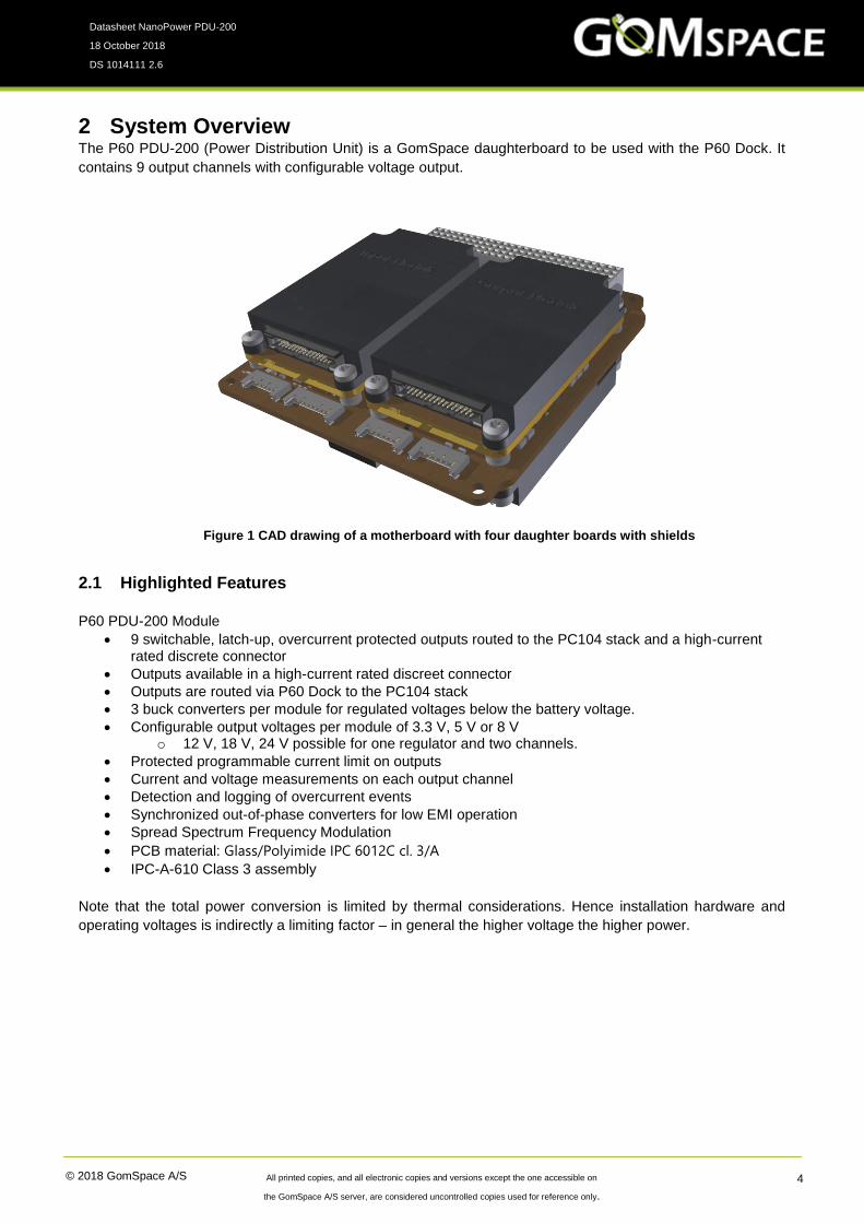
2 System Overview The P60 PDU-200 (Power Distribution Unit) is a GomSpace daughterboard to be used with the P60 Dock. It
contains 9 output channels with configurable voltage output.
2.1 Highlighted Features
P60 PDU-200 Module
• 9 switchable, latch-up, overcurrent protected outputs routed to the PC104 stack and a high-current rated discrete connector
• Outputs available in a high-current rated discreet connector
• Outputs are routed via P60 Dock to the PC104 stack
• 3 buck converters per module for regulated voltages below the battery voltage.
• Configurable output voltages per module of 3.3 V, 5 V or 8 V o 12 V, 18 V, 24 V possible for one regulator and two channels.
• Protected programmable current limit on outputs
• Current and voltage measurements on each output channel
• Detection and logging of overcurrent events
• Synchronized out-of-phase converters for low EMI operation
• Spread Spectrum Frequency Modulation
• PCB material: Glass/Polyimide IPC 6012C cl. 3/A
• IPC-A-610 Class 3 assembly
Note that the total power conversion is limited by thermal considerations. Hence installation hardware and
operating voltages is indirectly a limiting factor – in general the higher voltage the higher power.
Figure 1 CAD drawing of a motherboard with four daughter boards with shields

© 2018 GomSpace A/S All printed copies, and all electronic copies and versions except the one accessible on
the GomSpace A/S server, are considered uncontrolled copies used for reference only.
Datasheet NanoPower PDU-200
18 October 2018
DS 1014111 2.6
5
2.2 Block Diagram The PDU module contains 3 Buck converters that can be connected to each of the 9 output channels. HW
configuration during production fixes each output to a specific converter and sets the voltage of each converter.
An output channel can also be configured to unregulated battery voltage. All 9 outputs are available in the
motherboard stack connector, and only 6 of the channels are available in the TFM connector (together with a
few communication channels).
Figure 2 P60 PDU-200 block diagram

© 2018 GomSpace A/S All printed copies, and all electronic copies and versions except the one accessible on
the GomSpace A/S server, are considered uncontrolled copies used for reference only.
Datasheet NanoPower PDU-200
18 October 2018
DS 1014111 2.6
6
3 Connector Pinout
3.1 TFM Output Samtec TFM-115-02-L-DH
Note that the polarization key is located next to pin 30.
Pin Description Pin Description
1 Output 1 2 GND
3 Output 1 4 GND
5 SDA 6 SCL
7 Output 0 8 GND
9 Output 2 10 GND
11 SDA 12 SCL
13 Output 3 14 GND
15 VBAT 16 GND
17 VBAT 18 GND
19 Output 5 20 GND
21 VCC-internal 22 GND
23 CANH 24 CANL
25 Output 6 26 GND
27 Output 6 28 GND
29 CANH 30 CANL

© 2018 GomSpace A/S All printed copies, and all electronic copies and versions except the one accessible on
the GomSpace A/S server, are considered uncontrolled copies used for reference only.
Datasheet NanoPower PDU-200
18 October 2018
DS 1014111 2.6
7
3.2 FPC Debug Molex 51281-1894
Manual programming and test connector.
Pin Description
1 GND
2 VCC
3 RESET_NOT
4 JTAG_TDI
5 JTAG_TMS
6 JTAG_TCK
7 JTAG_TDO
8 GND
9 VCC
10 UART_RX (GOSH)
11 UART_TX (GOSH)
12 Not connected
13 Not connected
14 Not connected
15 Not connected
16 Not connected
17 Not connected
18 GND

© 2018 GomSpace A/S All printed copies, and all electronic copies and versions except the one accessible on
the GomSpace A/S server, are considered uncontrolled copies used for reference only.
Datasheet NanoPower PDU-200
18 October 2018
DS 1014111 2.6
8
4 Absolute Maximum Ratings Stresses above those listed under Absolute Maximum Ratings may cause permanent damage to the P60 PDU-
200. Exposure to absolute maximum rating conditions for extended periods may affect the reliability.
Symbol Description Min. Max. Unit
Tamb Operating Temperature -35 +85 °C
Vio Voltage on I2C/USART pins -0.1 3.4 V
5 Electrical Characteristics Parameter Condition Min. Typ. Max. Unit
Battery
- Voltage
Battery connection 8 volt
16 volt
32 volt
6.0
12.0
24.0
7.4
14.9
29.6
8.4
16.80
33.6
V
V
V
V_BAT
- Voltage
- Current, cont.
Raw battery voltage
(Depends on battery configuration)
H2-45 and H2-46
VCC power consumption 165 mW
VBAT power consumption Per converter enabled 80 mW
DC/DC converters, 0-2
Converter 0
Converter 1
Converter 2
3.3 V, 5 V, 8 V, 12 V, 18 V, 24 V
3.3 V, 5 V or 8 V
3.3 V, 5 V or 8 V
VBAT possible *
4.5 A
Output channel, 0-8 2 A
Latch-up time Per channel 20 ms
* View option sheet for RAW VBAT options
6 Physical Characteristics Description Value Unit
Mass with shield 57 g
Size 65.6 x 40.1 x 4.7 mm

© 2018 GomSpace A/S All printed copies, and all electronic copies and versions except the one accessible on
the GomSpace A/S server, are considered uncontrolled copies used for reference only.
Datasheet NanoPower PDU-200
18 October 2018
DS 1014111 2.6
9
7 Output Channel Efficiency This chapter shows the measured system efficiency, using the P60 system with an 8 V battery pack. The P60
dock has one ACU-200 and one PDU-200 module installed. The efficiencies are shown, not considering the
standby power consumption (600 mW). Hence the standby power consumption should be considering on a
power budget level, combined with the number of input/output channels and their expected efficiency at the
expected load.
Efficiency is measured from the battery input to the stack connector output. Hence it includes all losses in the
connections to/from the board and the P60 Dock power interface protection switches.
X-axis shows the output current in amps. The Y-axis shows the efficiency in percent. The configuration of the
PDU-200 module is one channel to one converter. In the case of multiple channels on one converter the
combined efficiency will be slightly larger.
0
10
20
30
40
50
60
70
80
90
100
0 0,5 1 1,5 2 2,5
Eff
icie
ncy [%
]
Current [A]
8 V battery - 3.3 V regulator - Stack output
0
10
20
30
40
50
60
70
80
90
100
0 0,5 1 1,5 2 2,5
Eff
ecie
ncy [%
]
Current [A]
7 V battery - 3.3 V regulator - Stack output

© 2018 GomSpace A/S All printed copies, and all electronic copies and versions except the one accessible on
the GomSpace A/S server, are considered uncontrolled copies used for reference only.
Datasheet NanoPower PDU-200
18 October 2018
DS 1014111 2.6
10
0
10
20
30
40
50
60
70
80
90
100
0 0,5 1 1,5 2 2,5
Eff
icie
ncy [%
]
Current [A]
7 V battery - 5.0 V regulator - Stack output
0
10
20
30
40
50
60
70
80
90
100
0 0,5 1 1,5 2 2,5
Eff
icie
ncy [%
]
Current [A]
8 V battery - 5.0 V regulator - Stack output

© 2018 GomSpace A/S All printed copies, and all electronic copies and versions except the one accessible on
the GomSpace A/S server, are considered uncontrolled copies used for reference only.
Datasheet NanoPower PDU-200
18 October 2018
DS 1014111 2.6
11
8
0
10
20
30
40
50
60
70
80
90
100
0 0,5 1 1,5 2 2,5
Eff
icie
ncy [%
]
Current [A]
8 V battery - CH2 unregulated - Stack output

© 2018 GomSpace A/S All printed copies, and all electronic copies and versions except the one accessible on
the GomSpace A/S server, are considered uncontrolled copies used for reference only.
Datasheet NanoPower PDU-200
18 October 2018
DS 1014111 2.6
12
Physical Layout The PDU PCB top under the shield has two connectors at the right edge and at the bottom left corner. Middle
left is a MCU and a FRAM. Top left is a LED. Middle right are three buck converters.
The bottom side has two FSI connectors to the left, Buck converters middle. Two ADC right side middle and
bottom left.
Figure 3 PDU module top
Figure 4 PDU module bottom

© 2018 GomSpace A/S All printed copies, and all electronic copies and versions except the one accessible on
the GomSpace A/S server, are considered uncontrolled copies used for reference only.
Datasheet NanoPower PDU-200
18 October 2018
DS 1014111 2.6
13
9 Disclaimer The information in this document is subject to change without notice and should not be construed as a
commitment by GomSpace. GomSpace assumes no responsibility for any errors that may appear in this
document.
In no event shall GomSpace be liable for incidental or consequential damages arising from use of this document
or the software and hardware described in this document.