Embed Size (px)
Citation preview

Piezo • Nano • Positioning
Nanopositioning / Piezoelectrics Piezo Systems, Fast Piezo Steering Mirrors

Typical Applications
� CD, DVD mastering, testing
� Image stabilization, resolution enhancement
� Photonics alignment & packaging
� Fiber optic switches
� Scanning interferometry
� Vibration cancellation
� Laser beam steering
� Adaptive optics
� Scanning microscopy
� Auto-focus systems
� Nanometrology
� Wafer and mask positioning / alignment
� Microlithography
� Fast tool servos
� Smart structures / structural deformation
� Nanopositioning
� Semiconductor test equipment
� Precision machining (non-circular turning,boring, grinding, polishing)
� Biotechnology
2-2
©P
hys
ikIn
stru
men
te(P
I)G
mb
H&
Co
.KG
2008
.Su
bje
ctto
chan
ge
wit
ho
ut
no
tice
.C
at12
0EIn
spir
atio
ns2
009
08/1
0.18
Piezo • Nano • Positioning
� 1- to 6-axis standard, OEMand custom designs
� Parallel kinematics andparallel metrology forbetter multi-axis accuracy
� Closed-loop operation withSGS and capacitive posi-tion sensors for higherlinearity and repeatability
� Integrated capacitiveposition sensors for sub-nanometer-resolution andstability
� Finite Element Analysis(FEA) computer-designedflexures for nanometerand microradian trajectorycontrol
� Invar, titanium, steel andaluminum versions foroptimized thermal match
� High-performance con-trollers and amplifiers(digital, analog, modular,
OEM) with 60 to 1500 Voutput ranges; Ultra-high-output power amplifiersfeaturing energy recoveryand 2000 W peak power
� Single- and multi-channeldigital controllers withdynamic digital lineari-zation (DDL) to eliminatetracking error
� Patented feedforward tech-nology and digital signalprocessing for faster set-tling and higher bandwidth
� Modular NanoAutomation®
piezo controllers with high-speed parallel interfaces
� Optional opto-isolatedinputs for maximum EMIimmunity
� Optimized mechanicaldesign, control algorithmsand software for highestthroughput
Nanopositioning Solutions from PI
Piezoelectric nanopositioning systems large (e. g. for precision machining),medium (e. g. for interferometry), small (e. g. for data storage medium testing)

Piezo • Nano • Positioning
Piezo Flexure Stages / High-Speed Scanning Systems
Nanopositioning / Piezoelectrics

2-4
©P
hys
ikIn
stru
men
te(P
I)G
mb
H&
Co
.KG
2008
.Su
bje
ctto
chan
ge
wit
ho
ut
no
tice
.C
at12
0EIn
spir
atio
ns2
009
08/1
0.18
Piezo • Nano • Positioning
Selection Guide: Single-Axis Piezo Stages
Models Description Travel [μm] Sensor Dynamics* Precision** Page
Nanometer Precision, Travel Ranges 15 μm to 1,800 μm
P-772 Ultra-compact flexure guided system 10 Capacitive ●●●●● ●●●●● 2-24
P-712 Compact scanner, fast, low profile, aperture, ideal for imaging 15 SGS ●●●●● ●●❍❍❍ 2-14
All models are precision flexureguided, and equipped with thepatented PICMA® long-life piezoactuators. Capacitive positionfeedback sensors are available
for the highest performanceapplications, alternatively, straingauge sensors are available aswell as open loop models.
P-753 Nanopositioning stage and actuator in one, very compact, fast and accurate 12, 25, 38 Capacitive ●●●●● ●●●●● 2-16
P-772 Smallest stage withdirect metrology. 12 μm
P-712 Low profile, low cost,30 μm
P-753 LISA Stage / actuator,to 38 μm
P-752 Fast & extremelyprecise to 30 μm
P-750 High-load stage, 75 μm P-611 100 μm, compact,low cost
P-631 OEM high-volume stage P-62x.1 Family: 50 to 1800 μm,compact
P-721, P-725: PIFOC® lenspositioners, 100 to 500 μm,
P-601 Flexure-guided actuator,100 to 400 μm
S-303 Phase shifter, very fast M-511.HD, M-714 Hybridstage, travel to 100 mm
Multi-Axis Piezo Stages: see p. 2-6
Piezo Motor Driven Long Travel Stages: see p. 4-19 ff
Notes on Specifications see p. 2-78 ff
P-752 Nanopositioning stage, very fast and accurate, outstanding guiding accuracy 15, 30 Capacitive ●●●●● ●●●●❍ 2-18
P-750 High load stage, outstanding guiding accuracy 75 Capacitive ●●●●❍ ●●●●● 2-24
P-611 Compact, low-cost. X, Z, XY and XYZ combinations 100 SGS ●●●❍❍ ●●●❍❍ 2-20
P-631 Compact precision OEM stage for high-volume applications 100, more Capacitive ●●●❍❍ ●●●●❍ 2-24on request
P-62x.1 PIHera® piezo nanopositioners, compact, very accurate, long travel ranges, 50 to 1800 Capacitive ●●●●❍ to ●❍❍❍❍ ●●●●❍ to ●●●❍❍ 2-22excellent value. X, XY and XYZ combinations
P-721, PIFOC® objective nanofocusing system, very fast and accurate, with QuickLock 100, 250, 500 Capacitive / SGS ●●●❍❍ ●●●●❍ / ●●❍❍❍ 2-26P-725 mounting system, direct metrology 2-28
P-2601 Closed-loop, with flexure guidance 110, 300, 400 SGS ●●●●❍ ●●❍❍❍ 1-68
S-303 Phase shifter, extremely precise, 25 kHz resonant frequency, optional sensors 3 Capacitive ●●●●● ●●●●● 2-96
M-511.HD, Hybrid drive: piezo & servo motor, extremely accurate, 2 nm linear encoder, Up to Linear Encoder ●●●●❍ ●●●●❍ 4-46M-714 long travel to 100 mm 100 mm
*Dynamics: Combination of system settling time / bandwidth / load capacity relative to the typical application of the product**Precision: Combination of guiding precision, sensor precision, resolution, relative to comparable products in class

2-5
Piezo • Nano • Positioning
P-518, P-528, P-558 Z/tip/tiltstages
N-515KNPH Non-magneticNEXLINE Hexapod
Selection Guide: Z & Z/Tip/Tilt Piezo Stages
Models Description Travel Sensor Dyna- Preci- Page
[μm / mrad] mics* sion**
Highly Responsive, Flexure Guided Piezo Nanopositioning Systems
P-720 PIFOC® objective nanofocusing system, very compact, for small objectives, open loop 100 – ●●❍❍❍ ●●❍❍❍ 2-25
P-721 PIFOC® objective nanofocusing system, very fast and accurate, 100 Capacitive / SGS ●●●❍❍ ●●●●❍ / 2-26with QuickLock mounting system, direct metrology ●●❍❍❍
All models are precision flexureguided, and equipped with thepatented PICMA® long-life piezo
actuators. Capacitive positionfeedback sensors are availablefor the highest performance
applications. Alternatively, straingauge sensors are available aswell as open loop models. Multi-
axis systems are based onparallel-kinematics with onemoving platform.
P-725 PIFOC® objective nanofocusing system, compact, light-weight, long travel ranges, 100, 250, 400 Capacitive ●●❍❍❍ ●●●❍❍ 2-28QuickLock mounting system, direct metrology
P-612.Z compactnanopositioner w/ aperture
P-601 Flexure guided OEM Z-actuator / stage, 100 to 400 μm
P-620.Z, P-622.Z Compact,long-travel stages, to 400 μm
P-732 High-Dynamicsscanning stage w/aperture
P-733.Z 100 μm Z-stage withaperture
P-541.Z Low- profile Z-/tip/tiltstage
Notes on Specificationssee p. 2-78 ff
P-726 PIFOC® high-power nanofocusing system for large objectives 100 Capacitive ●●●●● ●●●●● 2-32
P-721KTPZ PIFOC® nosepiece nanopositioning system, high stiffness, direct metrology 80 Capacitive ●●●❍❍ ●●●●❍ 2-25
P-721KPTZ High-load PIFOC® nosepiece nanopositioner, direct metrology 150 Capacitive ●●●●❍ ●●●●❍ 2-25
P-737 PIFOC® Z-axis microscopy piezo stage for high-resolution sample positioning and scanning to 250 SGS ●●❍❍❍ ●●●❍❍ 2-34
P-611.Z Compact, low-cost Z nanopositioning piezo stage 100 SGS ●●❍❍❍ ●●❍❍❍ 2-36
P-612.Z Compact nanopositioning Z-stage, clear aperture 100 SGS ●●❍❍❍ ●●❍❍❍ 2-38
P-601 Closed-loop, with flexure guidance 110, 300, 400 SGS ●●●●❍ ●●❍❍❍ 1-68
P-620.Z – PIHera® Z-axis nanopositioners, compact, very accurate, long travel range 50, 100, 250 Capacitive ●●●❍❍ ●●●❍❍ 2-40P-622.Z
P-732 High-dynamics vertical nanopositioning/scanning stage 15 Capacitive ●●●●❍ ●●●❍❍ 2-48
*Dynamics: Combination of system settling time /bandwidth / load capacity relative to the typicalapplication of the product
**Precision: Combination of guiding precision,sensor precision, resolution, relative to comparableproducts in class
P-733.Z Z scanning piezo stage 50 x 50 mm aperture, vacuum versions available 100 Capacitive ●●●❍❍ ●●●❍❍ 2-42
P-541.Z Low-profile Z-stage, 80 x 80 mm aperture 100 / 1 mrad Capacitive / SGS ●●❍❍❍ ●●●❍❍ 2-44
P-518, Z-axis and tip/tilt piezo stage platforms 66 x 66 mm clear aperture to 200 / Capacitive ●●●❍❍ ●●●●❍ 2-46P-528, P-558 4 mrad
N-510 Tripod Z-tip/tilt nanopositioning platform with NEXLINE® piezo motors 1.3 mm / Linear encoder ●●●❍❍ 2-4910 mrad
P-915KVPZ Vacuum-compatible piezo Z stage 45 Capacitive ●●●●❍ ●●●●❍ 2-48
P-915KLPZ Low-profile piezo objective scanner, open-loop 75 – ●●●●❍ ●●●❍❍ 2-48
N-515KNPH Nonmagnetic 6-axis piezo Hexapod precision positioning system with NEXLINE® to 10 mm / 6° Linear encoder ●●❍❍❍ ●●●❍❍ 2-49piezo motor actuators
N-510KHFS Tripod Z-Tip/Tilt nanopositioning platform with additional fine positioning 400 plus Capacitive ●●❍❍❍ ●●●●❍ 2-4940 μm
P-721, P-720 Compactnanofocusing systems
P-725 PIFOC® long travelnanofocusing system
P-726 Fast nanofocusingsystem for heavy objectives
P-721K PIFOC® nosepiecepositioners
P-737 microscopy Z-stage forsample positioning
P-611.Z Compact, low-cost,nanopositioning stage
P-725.xDD PIFOC® objective nanofocusing system, high-dynamics, direct-metrology 20 Capacitive /SGS ●●●●● ●●●●● 2-30
P-725.xDD PIFOC® high-dyna-mics piezo scanner
2-6
©P
hys
ikIn
stru
men
te(P
I)G
mb
H&
Co
.KG
2008
.Su
bje
ctto
chan
ge
wit
ho
ut
no
tice
.C
at12
0EIn
spir
atio
ns2
009
08/1
0.18
Piezo • Nano • Positioning
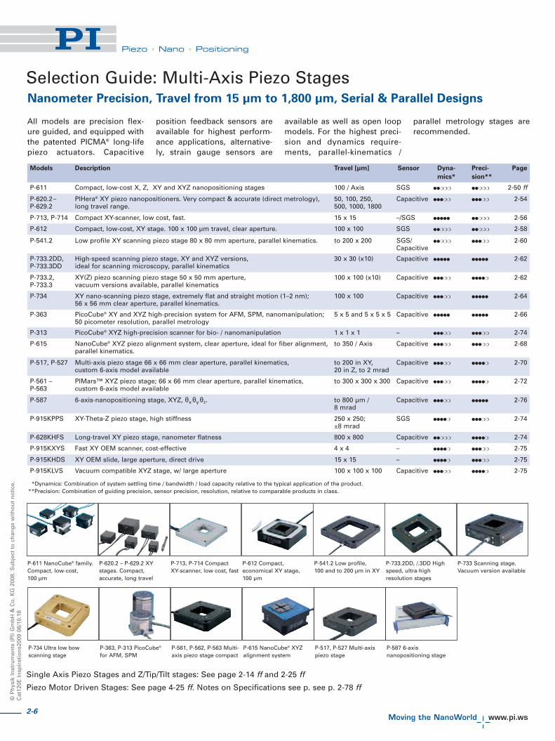
Selection Guide: Multi-Axis Piezo StagesNanometer Precision, Travel from 15 μm to 1,800 μm, Serial & Parallel Designs
Models Description Travel [μm] Sensor Dyna- Preci- Page
mics* sion**
P-611 Compact, low-cost X, Z, XY and XYZ nanopositioning stages 100 / Axis SGS ●●❍❍❍ ●●❍❍❍ 2-50 ff
P-620.2– PIHera® XY piezo nanopositioners. Very compact & accurate (direct metrology), 50, 100, 250, Capacitive ●●●❍❍ ●●●❍❍ 2-54P-629.2 long travel range. 500, 1000, 1800
All models are precision flex-ure guided, and equipped withthe patented PICMA® long-lifepiezo actuators. Capacitive
position feedback sensors areavailable for highest perform-ance applications, alternative-ly, strain gauge sensors are
available as well as open loopmodels. For the highest preci-sion and dynamics require-ments, parallel-kinematics /
parallel metrology stages arerecommended.
P-713, P-714 Compact XY-scanner, low cost, fast. 15 x 15 –/SGS ●●●●● ●●❍❍❍ 2-56
Single Axis Piezo Stages and Z/Tip/Tilt stages: See page 2-14 ff and 2-25 ff
Piezo Motor Driven Stages: See page 4-25 ff. Notes on Specifications see p. see p. 2-78 ff
P-612 Compact, low-cost, XY stage. 100 x 100 μm travel, clear aperture. 100 x 100 SGS ●●❍❍❍ ●●❍❍❍ 2-58
P-541.2 Low profile XY scanning piezo stage 80 x 80 mm aperture, parallel kinematics. to 200 x 200 SGS/ ●●❍❍❍ ●●●❍❍ 2-60Capacitive
P-733.2DD, High-speed scanning piezo stage, XY and XYZ versions, 30 x 30 (x10) Capacitive ●●●●● ●●●●● 2-62P-733.3DD ideal for scanning microscopy, parallel kinematics
P-733.2, XY(Z) piezo scanning piezo stage 50 x 50 mm aperture, 100 x 100 (x10) Capacitive ●●●❍❍ ●●●●❍ 2-62P-733.3 vacuum versions available, parallel kinematics
P-734 XY nano-scanning piezo stage, extremely flat and straight motion (1–2 nm); 100 x 100 Capacitive ●●●❍❍ ●●●●● 2-6456 x 56 mm clear aperture, parallel kinematics.
P-363 PicoCube® XY and XYZ high-precision system for AFM, SPM, nanomanipulation; 5 x 5 and 5 x 5 x 5 Capacitive ●●●●● ●●●●● 2-6650 picometer resolution, parallel metrology
P-313 PicoCube® XYZ high-precision scanner for bio- / nanomanipulation 1 x 1 x 1 – ●●●❍❍ ●●●❍❍ 2-74
P-615 NanoCube® XYZ piezo alignment system, clear aperture, ideal for fiber alignment, to 350 / Axis Capacitive ●●●❍❍ ●●●❍❍ 2-68parallel kinematics.
*Dynamics: Combination of system settling time / bandwidth / load capacity relative to the typical application of the product.**Precision: Combination of guiding precision, sensor precision, resolution, relative to comparable products in class.
P-517, P-527 Multi-axis piezo stage 66 x 66 mm clear aperture, parallel kinematics, to 200 in XY, Capacitive ●●●❍❍ ●●●●❍ 2-70custom 6-axis model available 20 in Z, to 2 mrad
P-561 – PIMars™ XYZ piezo stage; 66 x 66 mm clear aperture, parallel kinematics, to 300 x 300 x 300 Capacitive ●●●❍❍ ●●●●❍ 2-72P-563 custom 6-axis model available
P-587 6-axis-nanopositioning stage, XYZ, θxθyθz. to 800 μm / Capacitive ●●●❍❍ ●●●●● 2-768 mrad
P-915KPPS XY-Theta-Z piezo stage, high stiffness 250 x 250; SGS ●●●●❍ ●●●❍❍ 2-74±8 mrad
P-628KHFS Long-travel XY piezo stage, nanometer flatness 800 x 800 Capacitive ●●❍❍❍ ●●●●❍ 2-74
P-915KXYS Fast XY OEM scanner, cost-effective 4 x 4 – ●●●●❍ ●●●❍❍ 2-75
P-915KHDS XY OEM slide, large aperture, direct drive 15 x 15 – ●●●●❍ ●●●❍❍ 2-75
P-915KLVS Vacuum compatible XYZ stage, w/ large aperture 100 x 100 x 100 Capacitive ●●●❍❍ ●●●●❍ 2-75
P-611 NanoCube® family.Compact, low-cost,100 μm
P-620.2 – P-629.2 XYstages. Compact,accurate, long travel
P-713, P-714 CompactXY-scanner, low cost, fast
P-612 Compact,economical XY stage,100 μm
P-541.2 Low profile,100 and to 200 μm in XY
P-733.2DD, /.3DD Highspeed, ultra-highresolution stages
P-733 Scanning stage.Vacuum version available
P-734 Ultra low bowscanning stage
P-363, P-313 PicoCube®
for AFM, SPMP-561, P-562, P-563 Multi-axis piezo stage compact
P-615 NanoCube® XYZalignment system
P-517, P-527 Multi-axispiezo stage
P-587 6-axisnanopositioning stage

2-7
Piezo • Nano • Positioning
Piezo Flexure Stages /High-Speed Scanning Systems
Nanopositioning / Piezoelectrics
Linear Actuators & Motors
Fast Steering Mirrors /Active Optics
Piezo Drivers /Servo Controllers
Piezoelectrics in Positioning
Nanometrology
Micropositioning
Linear
Vertical & Tip/Tilt
2- and 3-Axis
6-Axis
Single-Channel
Multi-Channel
Modular
Accessories
Index
From Piezo Actuators to Piezo
Nanopositioning and Scanning
Systems
Piezo ceramic actuators are atthe heart of most PI nanoposi-tioning systems. These actua-tors provide sub-nanometerresolution and sub-millisec-ond response time by friction-less motion based on molecu-lar effects. To form a high per-formance nanopositioningsystem, the intrinsic advan-tages of the piezo drive haveto be complemented by a fric-tionless, stiff guidance systemand highly linear, responsivenanometrology sensors forposition feedback. Sophis-ticated digital servo systems,low noise drivers and controlalgorithms are necessary tosupport the mechanical part ofthe nanopositioning system.
Flexures – the Main
Mechanical Component
Flexure motion is based onthe elastic deformation (flex-
ing) of a solid material.Friction and stiction areentirely eliminated, and flex-ures exhibit high stiffness,load capacity and resistanceto shock and vibration.Flexures are maintenancefree and not subject to wear.They are vacuum compatible,operate over a wide tempera-ture range and require nei-ther lubricants nor com-pressed air for operation. PIflexures are optimized forhighest possible stiffness andstraightness / flatness in thenanometer realm combinedin many cases with integratedmotion amplifiers. This al-lows for extended travel up tothe millimeter range.
Excellent Guiding Accuracy
The multilink flexure guidingsystems employed in most PIpiezo nanopositioners elimi-nate cosine errors and pro-vide bidirectional flatnessand straightness in the
Piezo Systems
nanometer or microradianrange. This high precisionmeans that even the mostdemanding positioning taskscan be run bidirectionally forhigher throughput.
Lifetime / PICMA® Piezo
Actuators
PI nanopositioning systemsemploy the award-winningPICMA® piezo actuators, theonly actuators with co-firedceramic encapsulation. ThePICMA® piezo technology wasspecifically developed by PI’spiezo ceramic division to pro-vide higher performance andlifetime in nanopositioningapplications.
Multilayer piezo actuators aresimilar to ceramic capacitorsand are not affected by wearand tear. Read p. 2-12 ff fordetails.
CE & RoHS Compliance
All standard PI nanopositio-ning systems are fully CE andRoHS compliant.
Drive, sensors, mechanics and control electronics with software –components of PI’s positioning systems
Precision Flexure-Guided Nanopositioners and Scanners
P-733 low-profile XY and XYZ scanning stages
Wire-EDM cutting process provideshighest-accuracy flexure guidingsystems in compact nanopositioningstages

2-8
©P
hys
ikIn
stru
men
te(P
I)G
mb
H&
Co
.KG
2008
.Su
bje
ctto
chan
ge
wit
ho
ut
no
tice
.C
at12
0EIn
spir
atio
ns2
009
08/1
0.18
Piezo • Nano • Positioning
Measuring Nanometers: Stage Metrology Selection
Achieving nanometer andsubnanometer precisionrequires a stage internalmetrology system, capable ofmeasuring motion on thenanometer scale. The five pri-mary characteristics to con-sider when selecting a stagemetrology system are lineari-ty, sensitivity (resolution), sta-bility, bandwidth, and cost.Other factors include the abil-ity to measure the movingplatform directly and contactvs. noncontact measurement.Three types of sensors aretypically used in piezonanopositioning applica-tions—capacitive, strain, andLVDT. Table 1 summarizes thecharacteristics of each sensortype. For long travel ranges of1mm and above, classicalpiezo multilayer or stackdrives are replaced byPiezoWalk® motors. Theseunique drives are comple-mented by special optical lin-ear sensors to achievenanometer precision and lin-earities of 0.001%.
PI capacitive sensors meas-ure the gap between twoplates or one plate and a pla-nar, conducting surface basedon electrical capacitance.These sensors can bedesigned to become an inte-gral part of a nanopositioningsystem, with virtually noeffect on size and mass (iner-tia). Capacitive sensors offerthe highest resolution, stabili-
ty, and bandwidth. Theyenable direct measurementof the moving platform andare noncontact. Capacitivesensors also offer the highestlinearity (accuracy). PI'scapacitive sensors / controlelectronics use a high-fre-quency AC excitation signalfor enhanced bandwidth anddrift-free measurement stabil-ity (subnanometer stabilityover several hours, seep. 3-17 ff ). PI’s exclusive ILSlinearization system furtherimproves system linearity. Ifused with PI’s digital con-trollers, digital polynomiallinearization of mechanicsand electronics makes possi-ble an overall system linearityof better than 0.01 %.Capacitive sensors are themetrology system of choicefor the most demandingapplications.
A strain gauge sensor is aresistive metal or semicon-ductor film bonded to a piezostack or—for enhanced preci-sion—to the guiding systemof a flexure stage. It offershigh resolution and band-width and is typically chosenfor cost-sensitive applica-tions. As a contact type sen-sor, it measures indirectly, inthat the position of the mov-ing platform is inferred froma measurement at the lever,flexure or stack. PI employsfull-bridge implementationswith multiple strain gauges
per axis for enhanced thermalstability. PI's PICMA® drivetechnology also enableshigher performance of actua-tor-applied strain gauge sen-sors.
LVDT sensors measure mag-netic energy in a coil. A mag-netic core attached to themoving platform moves with-in a coil attached to the frameproducing a change in theinductance equivalent to theposition change. LVDT sen-sors provide noncontact,direct measurements of posi-tion. They are cost-effectiveand offer high stability andrepeatability.
Table 1
Sensor Type Sensitivity* Linearity* Sability* / Bandwidth* Metrology Type Excitation
(Resolution) Repeatability Signal
Capacitive Best Best Best Best Direct / Noncontact AC
Strain Better Good Good Better Inferred** (Indirect) / Contact DC
LVDT Good Good Better Good Direct / Noncontact AC
Linear Encoder Best*** Best*** Best*** Better Direct / Noncontact DC
*The ratings describe the influence of the sensor on the performance of the whole nanopositioning system. Resolution, linearity, repeatability, etc.specifications in the PI product data sheets indicate the performance of the complete system and include the controller, mechanics and sensor. Theyare verified using external nanometrology equipment (Zygo Interferometers). It is important not to confuse these figures with the theoretical per-formance of the sensor alone.
**Strain type sensors (metal foil, semiconductor, or piezoresistive) infer position information from strain.***for travel ranges >1mm
Response of a PI Nanopositioning stage to a square wave control signal clearlyshows the true sub-nm positional stability, incremental motion and bidirectionalrepeatability. Measured with external capacitive gauge, 20 pm resolution.

2-9
Piezo • Nano • Positioning
Piezo Flexure Stages /High-Speed Scanning Systems
Nanopositioning / Piezoelectrics
Linear Actuators & Motors
Fast Steering Mirrors /Active Optics
Piezo Drivers /Servo Controllers
Piezoelectrics in Positioning
Nanometrology
Micropositioning
Linear
Vertical & Tip/Tilt
2- and 3-Axis
6-Axis
Single-Channel
Multi-Channel
Modular
Accessories
Index
Parallel and Serial Designs
There are two ways toachieve multi-axis motion:parallel and serial kinematics.Serial kinematics (nested orstacked systems) are simplerand less costly to implement,but they have some limita-tions compared to parallelkinematics systems.
In a multi-axis serial kinemat-ics system, each actuator(and usually each sensor) isassigned to exactly onedegree of freedom. In a paral-lel kinematics multi-axis sys-
tem, all actuators act directlyon the same moving platform(relative to ground), enablingreduced size and inertia, andthe elimination of microfric-tion caused by movingcables. This way, the sameresonant frequency anddynamic behavior can beobtained for both the X and Yaxes. The advantages arehigher dynamics and scan-ning rates, better trajectoryguidance as well as betterreproducibility and stability.
Direct Parallel Metrology:
Multi-Axis Measurements Relative to a Fixed Reference
Parallel kinematics facilitatesimplementation of DirectParallel Metrology—mea-surement of all controlleddegrees of freedom relativeto ground. This is a more dif-ficult design to build but itleads to clear performanceadvantages.
A parallel metrology sensorsees all motion in its meas-urement direction, not justthat of one actuator. Thismeans that all motion isinside the servo-loop, no mat-ter which actuator may havecaused it, resulting in superi-or multi-axis precision,repeatability and flatness, asshown in the figure below.Direct parallel metrology also
allows stiffer servo settingsfor faster response. Off-axisdisturbances—external orinternal, such as inducedvibration caused by a faststep of one axis—can bedamped by the servo.
Flatness of an active-trajectory-controlled nanopositioningstage over 100 x 100 μm scanning range is about 1 nm
Principle of a PI XY-Theta-Z, minimum-inertial-mass,monolithic, parallel kinematics nanopositioningsystem. Accuracy, responsiveness and straight-ness/flatness are much better than in stackedmulti-axis (serial kinematics) systems.

2-10
©P
hys
ikIn
stru
men
te(P
I)G
mb
H&
Co
.KG
2008
.Su
bje
ctto
chan
ge
wit
ho
ut
no
tice
.C
at12
0EIn
spir
atio
ns2
009
08/1
0.18
Piezo • Nano • Positioning
Analog and Digital Controllers
PI offers the largest selectionof digital and analog piezodrivers / linear amplifiers andpiezo motion controllersworldwide.
The electronics play a keyrole for maximum perform-ance of piezoelectric nanopo-sitioning stages, tip/tilt mir-rors and actuators. Ultra-low-noise, high-stability servo-controllers and linear ampli-fiers are essential, becausepiezoelectric actuatorsrespond to even microvoltchanges of the control volt-age with motion.
For industrial applications,where maximum throughputis crucial, PI offers digital con-trol algorithms for dynamiclinearization and reduced set-tling times. For dynamic high-power applications, PI'sunique energy-recoverypower amplifiers provide upto 2000 W of peak power!
State-of-the-art PI digital con-trol systems offer severaladvantages over analog con-trol systems: coordinatetransformation, real-time lin-earity compensation andelimination of some types ofdrift. Digital controllers alsoallow virtually instantchanges of servo parametersfor different load conditions,etc. However, not all digitalcontrollers are created equal.Poor implementations canadd noise and lack certaincapabilities of a well-design-ed analog implementation,such as fast settling time,compatibility with advancedfeed-forward techniques, sta-bility and robust operation.
PI digital controllers candownload device-specificparameters from ID-chip-equipped nanopositioningstages, facilitating inter-changeability of nanomech-anisms and controllers.
All PI nanopositioning con-trollers (analog and digital)are equipped with one ormore user-tunable notch fil-ters. A controller with notchfilter can be tuned to providehigher bandwidth becauseside-effects of system reso-nances can be suppressedbefore they affect system sta-bility. For the most demand-ing step-and-settle applica-tions, PI’s exclusive Mach™InputShaping® implementa-tion is available as an option.
See page 2-100 ff Section fora complete overview on PI’spiezo drivers and controllers.

2-11
Piezo • Nano • Positioning
Piezo Flexure Stages /High-Speed Scanning Systems
Nanopositioning / Piezoelectrics
Linear Actuators & Motors
Fast Steering Mirrors /Active Optics
Piezo Drivers /Servo Controllers
Piezoelectrics in Positioning
Nanometrology
Micropositioning
Linear
Vertical & Tip/Tilt
2- and 3-Axis
6-Axis
Single-Channel
Multi-Channel
Modular
Accessories
Index
Piezo nanopositioning systemsare significant investmentsand PI believes in optimizingthe performance of every cus-tomer’s system. PI individuallytests every stage and opti-mizes the static and dynamicperformance for the cus-tomer’s application. Themetrology test protocol is partof the system’s delivery pack-age. It shows the customerwhat the performance of thesystem was at the time ofdelivery and which systemcomponents belong together.For PI every metrology proce-dure and its recording is aquality assurance instrument,and only nanopositioning sys-tems which meet their specifi-cations will leave the premises.
Furthermore, PI makes signifi-cant continuing investmentsin improved-quality, higher-performance nanometrologyequipment so that we candeliver better value to our cus-tomers.Because a nanomechanism canonly be as accurate as theequipment it was tuned andtested with, PI closed-loopstages are measured exclusive-ly with prestigious Zygo inter-ferometers. PI’s nanometrolo-gy metrology laboratories areseismically, electromagnetical-ly and thermally isolated, withtemperatures controlled to bet-ter than 0.25 °C / 24 hrs. We areconfident that our metrologycapabilities and procedures arethe benchmark for the industry.
Test & Metrology Protocol for Piezo SystemsGetting What You Bargained For
0.10
-0.10
-0.05
0.00
0.05
1000 10 20 30 40 50 60 70 80 90
Nonlinearity
Control Input [μm]
Non
linea
rity
[%]
100
0
10
20
30
40
50
60
70
80
90
1000 10 20 30 40 50 60 70 80 90
Displacement Curves
Control Input [μm]
Dis
plac
emen
t[μm
]
18 :31
P-517.6CD - Linearity
Protocol No.: FM 7.5-16 A2File: 191933-Y.cal 2005-08-23
Ctrl In Output + nonlin nonlin[μm] [μm] [μm] [%]
0.000 0.000 0.000 0.0005.000 5.000 0.000 0.000
10.000 10.002 0.000 0.00015.000 15.003 0.001 0.00120.000 20.005 0.003 0.00325.000 25.005 0.001 0.00130.000 30.007 0.003 0.00335.000 35.009 0.005 0.00540.000 40.008 0.003 0.00345.000 45.012 0.005 0.00550.000 50.008 0.002 0.00155.000 55.010 0.002 0.00260.000 60.010 0.002 0.00265.000 65.008 -0.001 -0.00170.000 70.009 -0.001 -0.00175.000 75.010 0.000 0.00080.000 80.011 0.000 0.00085.000 85.013 0.002 0.00290.000 90.011 -0.001 -0.00195.000 95.012 0.000 0.000
100.000 100.013 0.000 0.000
Control Function: Expansion = 1.000134*Ctrl_In + 0.0000 μm
Measurement Results
Customer PI internCustomer Ref No.PI Order No.
Order Info
Measurement Device Zygo ZMI 2000Meas. Device Type Laser InterferometerTemperature 22.2 °CAir Pressure 1011.8 mbarHumidity 29.0 %Measurement Date 18:30:29, 2005-08-23Meas. Program PZTCalib 7.0.3 Testversion Examiner msaMin. Ctrl Input 0.0 μmMax. Ctrl Input 100.0 μmStep Size 5.0 μmTime Delay 0.5 s
Measurement Setup
Stage P-517.6CDSer. No. 191933Commanded Axis YMeasured Axis YFeedback Sensor CAP SENSORDesign StandardNominal Oper. Voltage 100VNominal Expansion X: 100μm, Y: 100μmController E-710.6CDCalibration Type Standard, via analog control input
System Setup
Performance Test Protocol
Physik Instrumente (PI) GmbH & Co. KG, Auf der Römerstraße 1, 76228 Karlsruhe - Phone (+49) 721-4846-0, Fax (+49) 721-4846-100, e-mail [email protected]
All PI nanoposition-ing systems comewithextensive systemperformance docu-mentation
An S-340 2-axis fast steering mirror platformmeasured with a Zygo interferometer
An S-334 long-range 2-axis fast steering mirrormeasured with a Moeller Wedel autocollimator

2-12
©P
hys
ikIn
stru
men
te(P
I)G
mb
H&
Co
.KG
2008
.Su
bje
ctto
chan
ge
wit
ho
ut
no
tice
.C
at12
0EIn
spir
atio
ns2
009
08/1
0.18
Piezo • Nano • Positioning
PI has 4 decades of experiencewith piezo ceramic actuators inmotion control applications inindustry and research. CurrentlyPI employs more than 100 peo-ple fully dedicated to piezo cera-mic research, development andproduction. Extensive know-how and the most modernequipment make for the uniqueflexibility and worldwide lead-ership in piezo matters.
PI piezo actuators not onlyshow an optimal combination
of travel and stiffness, but arealso designed for maximumlifetime under actual operatingconditions in industrial envi-ronments.
Maximum lifetime means highestpossible reliability. PI’s award-winning, patented PICMA® actua-tors are based upon the newesttechnology which reduces thefailure rate by a factor 10 com-pared to conventionally designedmultilayer actuators.
Long Term Tests Prove DC
Reliability
PI’s monolithic ceramic-encap-sulated design provides betterhumidity protection than con-ventional polymer-film insula-tion. Diffusion of water mole-cules into the insulation layer isgreatly reduced by the use ofco-fired, outer ceramic encap-sulation. Humidity is the maininfluence on the long-term reli-ability in low-dynamics orquasi-static operation modes,where the piezo actuator is sup-plied with a DC voltage tomaintain a position for a longtime.
Comparative tests with bothPICMA® and conventional mul-tilayer piezo actuators haveproven the positive effects ofthe ceramic encapsulation.While polymer-coated piezostypically only survive 30 daysof continuous operation - PIC-MA® actuators are still workingafter more than 4 years!
PICMA® award-winning multilayer piezo actuators feature full-ceramic insulation
PICMA® piezo actua-tors (lower curve)
compared with poly-mer-insulated multi-
layer piezo actua-tors. PICMA® actua-tors are insensitiveto high humidity inthis test. In conven-tional actuators, the
leakage currentbegins to rise afteronly a few hours—
an indication ofdegradation of the
insulation andreduced lifetime.
Full-Ceramic Encapsulation & Patented Design
PICMA® Piezo Actuators—Extreme Lifetime, for IndustrialReliability Requirements
Results of an accel-erated DC-lifetime-
test of PICMA® actu-ators compared to
conventional actua-tors (100 V DC,
room temperature,90% R.H.). The
expected MTTF(Mean Time To
Failure) for PICMA®
is 80 years (700 000hrs of continuous
operation). All of thepolymer-insulated
samples have failedafter 1,600 hrs
(MTTF 805 hrs = 1month)

2-13
Piezo • Nano • Positioning
Piezo Flexure Stages /High-Speed Scanning Systems
Nanopositioning / Piezoelectrics
Linear Actuators & Motors
Fast Steering Mirrors /Active Optics
Piezo Drivers /Servo Controllers
Piezoelectrics in Positioning
Nanometrology
Micropositioning
Linear
Vertical & Tip/Tilt
2- and 3-Axis
6-Axis
Single-Channel
Multi-Channel
Modular
Accessories
Index
Continuous Dynamic
Operation
Here, the well-known lifetime-limiting factors of conventionaldesigns are humidity, crack for-mation inside the ceramic lead-ing to rising leakage currentsand delamination of electrodesunder extreme dynamic condi-tions.
PI reduces the cracking proba-bility by a special patenteddesign where segmented slotstake care of excessive tensionalstresses. Furthermore, the spe-cial electrode design ensuresexcellent, stable, electric con-tact even after billions ofcycles.
PICMA® multilayer piezo actua-tors show no significant de-crease in displacement evenafter many billions of cycles.
Long-Term Test under
Cryogenic Conditions
To suit an application requiring10 years minimum lifetimeunder cryogenic conditions,accelerated lifetime tests withPICMA® piezo actuators havebeen successfully performed.Inserted in a cryogenic bath ofliquid nitrogen (75 K), the piezois placed in a vacuum chamber(2 • 10-3 mbar) and subjected todynamic operation at 90 % ofthe maximum voltage range(>105 V) with an operating fre-quency up to 1000 Hz. After onemonth of continuous operationthere were no degradations inpiezo performance to be meas-ured, neither mechanic con-cerning the displacement, norelectrical concerning electricalcapacitance or resonant fre-quency (Dr. Bosotti et al.,University of Milano, Italy,2005).
Large Operating Temperature
Range , Optimum UHV
Compatibility—Minimum
Outgassing
Another advantage of fullyceramic-encapsulation PICMA®
actuators is the extended oper-ating temperature range, up to150 °C, a huge improvementover the 80 °C limit commonfor other, polymer-insulated,monolithic actuators. The heatgeneration in dynamic opera-tion is proportional to the oper-ating frequency. Thus, a higheroperating temperature allowsfor higher operating frequen-cies and duty cycles. Addi-tionally, the lack of polymerinsulation and the high Curietemperature make for optimalultra-high-vacuum compatibili-ty (no outgassing / high bake-out temperatures, up to 150 °C).
AC tests were per-formed for 4.0 x 10⁹cycles at 8 samples
PICMA® 5x5x18 usinga 116 Hz-sine wave
excitation (1.0 x 10⁷cycles per day) at aunipolar operating
voltage of 100 V, 15MPa preload. Controlmeasurements were
taken every 109cycles. There was nosignificant decrease
in displacement.

2-14
©P
hys
ikIn
stru
men
te(P
I)G
mb
H&
Co
.KG
2008
.Su
bje
ctto
chan
ge
wit
ho
ut
no
tice
.All
dat
aar
esu
per
sed
edb
yan
yn
ewre
leas
e.T
he
new
est
rele
ase
for
dat
ash
eets
isav
aila
ble
for
do
wn
load
atw
ww
.pi.w
s.C
at12
0EIn
spir
atio
ns2
009
08/1
0.18
Piezo • Nano • Positioning
P -712 piezo scanners are idealfor applications where limitedspace requires small-sizedequipment. The high resonantfrequency allows for fast linearscanning with 30 μm travel inone axis and provides settlingtimes of about 5 ms. The P-712linear scanner is offered in twoversions, one with SGS posi-tion sensors for closed-loopoperation, and one withoutsensors for open-loop.
A similar XY version is availa-ble with product number P-713/ P-714 (see p. 2-56).
Excellent Guiding Accuracy
Flexures optimized with FiniteElement Analysis (FEA) areused to guide the stage. FEAtechniques are used to give thedesign the highest possiblestiffness in, and perpendicularto, the direction of motion, andto minimize linear and angularrunout. Flexures allow extre-mely high-precision motion, nomatter how minute, as they arecompletely free of play and fri-ction.
Electric discharge machining(EDM) with fine cutting wires isused to obtain the requiredprecision for the flexures whichmake up the guidance systemand determine the stiffness.
Optional Position Control
High-resolution, broadband,strain gauge sensors (SGS) areapplied to appropriate loca-tions on the drive train andmeasure the displacement ofthe moving part of the stagerelative to the base indirectly.The SGS sensors assure opti-mum position stability in thenanometer range and fast res-ponse.
Ceramic Insulated Piezo
Actuators Provide Long
Lifetime
Highest possible reliability isassured by the use of award-winning PICMA® multilayerpiezo actuators. PICMA® actua-tors are the only actuators onthe market with ceramic-onlyinsulation, which makes them
resistant to ambient humidityand leakage-current failures.They are thus far superior toconventional actuators in relia-bility and lifetime.
P-712 Low-Profile Piezo ScannerCompact OEM System
� High Dynamic, to 5 ms Settling Time
� Travel Range up to 40 μm
� Resolution to 0.2 nm
� Compact Design with Low Profile, 40 x 40 x 6 mm
� Clear Aperture 25 x 15 mm
� PICMA® High-Power Actuators
Ordering Information
P-712.10L
Low-Profile OEM Nanoscanner,40 μm, Open-Loop
P-712.1SL
Low-Profile OEM Nanoscanner,30 μm, SGS-Sensor
Settling time for the P -712 at 30 μm is in the 5 ms range
P-712 piezo scanner with up to 40 μm travel range
Application Examples
� Optical path tuning
� Biotechnology
� Medical technology
� Image processing /stablilization
� CCD / CMOS cameratechnology
The P -713 XY-scanner is based on the same principle as the P -712 offering atravel range of 15 x 15 μm and a very high resonant frequency of over 2 kHz

2-15
Piezo • Nano • Positioning
Piezo Flexure Stages /High-Speed Scanning Systems
Nanopositioning / Piezoelectrics
Linear Actuators & Motors
Fast Steering Mirrors /Active Optics
Piezo Drivers /Servo Controllers
Piezoelectrics in Positioning
Nanometrology
Micropositioning
Linear
Vertical & Tip/Tilt
2- and 3-Axis
6-Axis
Single-Channel
Multi-Channel
Modular
Accessories
Index
Technical Data
Model P-712.1SL P-712.10L Units Tolerance
Active axes X X
Motion and positioning
Integrated sensor SGS –
Open-loop travel, -20 to +120 V 40 40 μm min. (+20 %/0 %)
Closed-loop travel 30 – μm calibrated
Closed-loop resolution 2 – nm typ.
Open-loop resolution 0.2 0.2 nm typ.
Linearity, closed-loop 0.3 – % typ.
Repeatability ±5 – nm typ.
Pitch ±5 ±5 μrad typ.
Yaw ±20 ±20 μrad typ.
Mechanical properties
Stiffness in motion direction 0.6 0.6 N/μm ±20 %
Unloaded resonant frequency 1550 1550 Hz ±20 %
Resonant frequency under load 1090 (20 g) 1090 (20 g) Hz ±20 %
Push/pull force capacity in motion direction 6 6 N Max.
Load capacity 5 5 N Max.
Lateral Force 6 6 N Max.
Drive properties
Ceramic type PICMA® P-882 PICMA® P-882
Electrical capacitance 0.3 0.3 μF ±20 %
Dynamic operating current coefficient 1.3 1.3 μA/(Hz • μm) ±20 %
Miscellaneous
Operating temperature range -20 to 80 -20 to 80
Material Stainless steel Stainless steel
Dimensions 40 x 40 x 6 40 x 40 x 6 mm
Mass 0.095 0.095 kg ±5 %
Cable length 1.5 1.5 m ±10 mm
Voltage connection LEMO LEMO
Sensor connector LEMO –
Recommended controller / amplifierSingle-channel (1 per axis): E-610 servo controller / amplifier (p. 2-110), E-625 servo controller, bench-top (p. 2-114)
P-712 dimensions in mm

©P
hys
ikIn
stru
men
te(P
I)G
mb
H&
Co
.KG
2008
.Su
bje
ctto
chan
ge
wit
ho
ut
no
tice
.All
dat
aar
esu
per
sed
edb
yan
yn
ewre
leas
e.T
he
new
est
rele
ase
for
dat
ash
eets
isav
aila
ble
for
do
wn
load
atw
ww
.pi.w
s.C
at12
0EIn
spir
atio
ns2
009
08/1
0.18
Piezo • Nano • Positioning
The P-753 LISA (Linear StageActuators) high-speed nanopo-sitioners can be used both aslinear actuators or as transla-tion stages. They are equippedwith capacitive feedback sen-sors, frictionless, flexure guid-ing systems andhigh-performance piezo drivesproviding a positioning andscanning range of up to 38 μm
with very fast settling time andextremely low tip/tilt error.
Direct-Drive Design for Fastest
Response
The direct-drive design, togeth-er with careful attention tomass minimization, results insignificant reduction in inertialrecoil forces applied to the sup-porting structures, enhancingoverall system response,throughput and stability withsettling times in the millisec-ond range.
PI's proprietary capacitive sen-sors measure position directlyand without physical contact.They are free of friction andhysteresis, a fact which, incombination with the position-ing resolution of well under1 nm, makes it possible toachieve very high levels of line-arity. A further advantage ofdirect metrology with capaci-
tive sensors is the high phasefidelity and the high bandwidthof up to 10 kHz.
Automatic Configuration
The „.CD“ versions are equip-ped with an ID-chip that storesall individual stage data andservo-control parameters. Thisdata is read out automaticallyby the AutoCalibration Func-tion of PI's digital piezo con-trollers. Thus, digital control-lers and nanopositioning sta-ges with ID-chip can be operat-ed in any combination.
High Reliability and Long
Lifetime
The compact P-753 LISA sys-tems are equipped with pre-loaded PICMA® high-perfor-mance piezo actuators whichare integrated into a sophisti-cated, FEA-modeled, flexureguiding system. The PICMA®
actuators feature cofiredceramic encapsulation andthus offer better performanceand reliability than convention-al piezo actuators. Actuators,guidance and sensors aremaintenance-free and not sub-ject to wear, and thus offer anextraordinary reliability.
High-Dynamics, Very Stable Piezo Nanopositioner
P-753 LISA Linear Actuator & Stage
Ordering Information
P-753.11C
LISA High-DynamicsNanopositioning System, 12 μm,Direct Metrology, Capacitive Sensor,LEMO Connector
P-753.21C
LISA High-DynamicsNanopositioning System, 25 μm,Direct Metrology, Capacitive Sensor,LEMO Connector
P-753.31C
LISA High-DynamicsNanopositioning System, 38 μm,Direct Metrology, Capacitive Sensor,LEMO Connector
P-753.1CD*
LISA High-DynamicsNanopositioning System, 12 μm,Direct Metrology, Capacitive Sensor,Sub-D Connector
P-753.2CD*
LISA High-DynamicsNanopositioning System, 25 μm,Direct Metrology, Capacitive Sensor,Sub-D Connector
P-753.3CD*
LISA High-DynamicsNanopositioning System, 38 μm,Direct Metrology, Capacitive Sensor,Sub-D Connector
*Vacuum versions to 10-9 hPa areavailable as P-753.xUD, non-mag-netic vacuum versions can beordered as P-753.xND.
Application Examples
� Disc-drive-testing
� Metrology
� Nanopositioning
� Scanning microscopy
� Photonics / integratedoptics
� Interferometry
� Biotechnology
� Micromanipulation
� Versatile Design: Flexure Stage or Actuator
� Resolution 0.05 nm, Rapid Response
� Capacitive Sensors for Highest Linearity
� Frictionless Precision Flexure Guidance for Frictionless,
Ultra-Straight Motion
� Outstanding Lifetime Due to PICMA® Piezo Actuators
� Vacuum-Compatible and Nonmagnetic Versions Available
P-753.11C LISA nano-precision actuators / positioning stages
2-16

2-17
Piezo • Nano • Positioning
Piezo Flexure Stages /High-Speed Scanning Systems
Nanopositioning / Piezoelectrics
Linear Actuators & Motors
Fast Steering Mirrors /Active Optics
Piezo Drivers /Servo Controllers
Piezoelectrics in Positioning
Nanometrology
Micropositioning
Linear
Vertical & Tip/Tilt
2- and 3-Axis
6-Axis
Single-Channel
Multi-Channel
Modular
Accessories
IndexTechnical Data
Model P-753.11C P-753.21C P-753.31C P-753.1CD P-753.2CD P-753.3CD Units Tolerance
Active axes X X X X X X
Motion and positioning
Integrated sensor Capacitive Capacitive Capacitive Capacitive Capacitive Capacitive
Closed-loop travel 12 25 38 12 25 38 μm calibrated
Closed-loop / open-loop resolution 0.05 0.1 0.2 0.05 0.1 0.2 nm typ., full travel
Linearity, closed-loop 0.03 0.03 0.03 0.03 0.03 0.03 % typ.
Repeatability ±1 ±2 ±3 ±1 ±2 ±3 nm typ.
Pitch / yaw ±5 ±7 ±10 ±5 ±7 ±10 μrad typ.
Mechanical properties
Stiffness in motion direction 45 24 16 45 24 16 N/μm ±20 %
Unloaded resonant frequency 5.6 3.7 2.9 5.6 3.7 2.9 Hz ±20 %
Resonant frequency @ 200 g 2.5 1.7 1.4 2.5 1.7 1.4 Hz ±20 %
Push/pull force capacity 100 / 20 100 / 20 100 / 20 100 / 20 100 / 20 100 / 20 N Max.in motion direction
Load capacity 10 / 2 10 / 2 10 / 2 10 / 2 10 / 2 10 / 2 kg Max.
(vertical/horizontal mounting)
Drive properties
Ceramic type PICMA® P-885 PICMA® P-885 PICMA® P-885 PICMA® P-885 PICMA® P-885 PICMA® P-885
Electrical capacitance 1.5 3.1 4.6 1.5 3.1 4.6 μF ±20 %
Dynamic operating current coefficient 12 15 15 12 15 15 μA/(Hz • μm) ±20 %
Miscellaneous
Operating temperature range -20 to 80 -20 to 80 -20 to 80 -20 to 80 -20 to 80 -20 to 80 °C
Material Stainless steel Stainless steel Stainless steel Stainless steel Stainless steel Stainless steel
Dimensions 44 x 30 x 15 44 x 30 x 62 44 x 30 x 80 44 x 30 x 15 44 x 30 x 62 44 x 30 x 80 mm
Mass 0.15 0.205 0.25 0.16 0.215 0.26 kg ±5 %
Cable length 1.5 1.5 1.5 1.5 1.5 1.5 m ±10 mm
Sensor / voltage connection LEMO LEMO LEMO Sub-D Special Sub-D Special Sub-D Special
Resolution of PI Piezo Nanopositioners is not limited by friction or stiction. Value given is noise equivalent motion with E-503 (p. 2-146) amplifier.Recommended controller / amplifierLEMO connector: E-500 (p. 2-142) piezo controller system with E-505 high-power amplifier (p. 2-147) and E-509 servo module (p. 2-152)Sub-D special connector: E-610 servo controller / amplifier card (p. 2-110), E-625 servo controller, bench-top (p. 2-114), E-665 high-power display controller, bench-top (p. 2-116),E-753 digital controller (p. 2-108)
P-753.1 dimensions in mm,max. torque at M2.5 threads:30 Ncm
Picture sub text 03P-753.2 dimensions in mm, max.torque at M2.5 threads: 30 Ncm
P-753.3 dimensions in mm, max.torque at M2.5 threads: 30 Ncm

©P
hys
ikIn
stru
men
te(P
I)G
mb
H&
Co
.KG
2008
.Su
bje
ctto
chan
ge
wit
ho
ut
no
tice
.All
dat
aar
esu
per
sed
edb
yan
yn
ewre
leas
e.T
he
new
est
rele
ase
for
dat
ash
eets
isav
aila
ble
for
do
wn
load
atw
ww
.pi.w
s.C
at12
0EIn
spir
atio
ns2
009
08/1
0.18
Piezo • Nano • Positioning
High-Dynamics, Very Stable Piezo Scanner with Extreme Guiding Accuracy
P-752 High Precision Nanopositioning Stage
P-752 series high-speed nano-positioning stages are extre-mely precise devices, provid-ing a positioning and scanningrange up to 30 μm with veryrapid settling and extremelylow tip/tilt errors. These stageswere specially designed forhigh-speed dithering and diskdrive testing applications.
Direct-Drive Design for Fastest
Response
The direct-drive design, toget-her with careful attention tomass minimization, results insignificant reduction in inertialrecoil forces applied to thesupporting structures, enhanc-ing overall system response,throughput and stability.In combination with theE-500 controller system theP-752.11C stage with 300 gload settles to better than 1 %with less 10 msec.
P-752 stages are equipped withcapacitive sensors providingsub-nanometer resolution andstability. PI's proprietary capac-itive sensors measure positiondirectly and without physicalcontact. They are free of fric-tion and hysteresis, a factwhich, in combination with thepositioning resolution of wellunder 1 nm, makes it possibleto achieve very high levels of
linearity. Further advantages ofdirect metrology with capaci-tive sensors are the high phasefidelity and the high bandwidthof up to 10 kHz.
Automatic Configuration
The “.CD” versions are equip-ped with an ID-chip that storesall individual stage data andservo-control parameters. Thisdata is read out automaticallyby the AutoCalibration functionof PI's digital piezo controllers.Thus, digital controllers andnanopositioning stages withID-chip can be operated in anycombination.
Higher Precision in Periodic
Motion
The highest dynamic accuracyin scanning applications ismade possible by the DDLalgorithm, which is availablein most of PI's modern digitalcontrollers. DDL eliminatestracking errors, improvingdynamic linearity and usablebandwidth by up to threeorders of magnitude!
High Reliability and Long
Lifetime
The compact P-752 systemsare equipped with preloaded
PICMA® high-performance pie-zo actuators which are inte-grated into a sophisticated,FEA-modeled, flexure guidingsystem. The PICMA® actuatorsfeature cofired ceramic encap-sulation and thus offer betterperformance and reliabilitythan conventional piezo actua-tors. Actuators, guidance andsensors are maintenance-freeand not subject to wear, andthus offer an extraordinary reli-ability.
� 0.1 nm Resolution, Fast Response
� Travel to 35 μm
� Capacitive Sensors for Highest Linearity
� Flexure Guidance for Frictionless, Ultra-Straight Motion
� Outstanding Lifetime Due to PICMA® Piezo Actuators
Application Examples
� Disc-drive-testing
� Metrology
� Nanopositioning
� Scanning microscopy
� Photonics / integratedoptics
� Interferometry
� Biotechnology
� Micromanipulation
Ordering Information
P-752.11C
High-Dynamics PiezoNanopositioning System, 15 μm,Direct Metrology, Capacitive Sensor,LEMO Connector
P-752.21C
High-Dynamics PiezoNanopositioning System, 30 μm,Direct Metrology, Capacitive Sensor,LEMO Connector
P-752.1CD
High-Dynamics PiezoNanopositioning System, 15 μm,Direct Metrology, Capacitive Sensor,Sub-D Connector
P-752.2CD
High-Dynamics PiezoNanopositioning System, 30 μm,Direct Metrology, Capacitive Sensor,Sub-D Connector
P-752.11C piezo nanopositioning system
Typical 0.5 μrad bidirectional trajectory repeatability (P-752.11C stage) means processesmay be performed bidirectionally for twice the productivity
2-18

2-19
Piezo • Nano • Positioning
Piezo Flexure Stages /High-Speed Scanning Systems
Nanopositioning / Piezoelectrics
Linear Actuators & Motors
Fast Steering Mirrors /Active Optics
Piezo Drivers /Servo Controllers
Piezoelectrics in Positioning
Nanometrology
Micropositioning
Linear
Vertical & Tip/Tilt
2- and 3-Axis
6-Axis
Single-Channel
Multi-Channel
Modular
Accessories
Index
Technical Data
Model P-752.11C P-752.1CD P-752.21C P-752.2CD Units Tolerance
Active axes X X X X
Motion and positioning
Integrated sensor Capacitive Capacitive Capacitive Capacitive
Open-loop travel, -20 to +120 V 20 20 35 35 μm min. (+20 %/-0 %)
Closed-loop travel 15 15 30 30 μm calibrated
Closed-loop / open-loop resolution 0.1 0.1 0.2 0.2 nm typ.
Linearity, closed-loop 0.03 0.03 0.03 0.03 % typ.
Repeatability ±1 ±1 ±2 ±2 nm typ., full travel
Pitch / yaw ±1 ±1 ±1 ±1 μrad typ.
Mechanical properties
Stiffness in motion direction 30 30 20 20 N/μm ±20 %
Unloaded resonant frequency 3200 3200 2100 2100 Hz ±20 %
Resonant frequency @ 300 g 980 980 600 600 Hz ±20 %
Push/pull force capacity 100 / 10 100 / 10 100 / 10 100 / 10 N Max.in motion direction
Load capacity 30 30 30 30 N Max.
Drive properties
Ceramic type PICMA® P-885 PICMA® P-885 PICMA® P-885 PICMA® P-885
Electrical capacitance 2.1 2.1 3.7 3.7 μF ±20 %
Dynamic operating current coefficient 17 17 15 15 μA/(Hz • μm) ±20 %
Miscellaneous
Operating temperature range -20 to 80 -20 to 80 -20 to 80 -20 to 80 °C
Material Stainless steel Stainless steel Stainless steel Stainless steel
Dimensions 66 x 40 x 13.5 66 x 40 x 13.5 84 x 40 x 13.5 84 x 40 x 13.5 mm
Mass 0.25 0.25 0.35 0.35 kg ±5 %
Cable length 1.5 1.5 1.5 1.5 m ±10 mm
Sensor / voltage connection LEMO Sub-D Special LEMO Sub-D Special
Resolution of PI Piezo Nanopositioners is not limited by friction or stiction. Value given is noise equivalent motion with E-503 (p. 2-146) amplifier.
Recommended controller / amplifierLEMO connector: E-500 piezo controller system (p. 2-142) with E-505 high-power amplifier (p. 2-147) and E-509 servo module (p. 2-152)Sub-D special connector: E-610 servo controller / amplifier (p. 2-110), E-625 servo controller, bench-top (p. 2-114), E-665 high-power display controller, bench-top(p. 2-116), E-753 digital controller (p. 2-108)
Response of a P-752.11C to a square wave control signal with 3 nm amplitude showstrue sub-nm positional stability, incremental motion and bidirectional repeatability(measured with E-501 & E-503.00 & E-509.C1 controller, bandwidth set to 240 Hz)

2-20
©P
hys
ikIn
stru
men
te(P
I)G
mb
H&
Co
.KG
2008
.Su
bje
ctto
chan
ge
wit
ho
ut
no
tice
.All
dat
aar
esu
per
sed
edb
yan
yn
ewre
leas
e.T
he
new
est
rele
ase
for
dat
ash
eets
isav
aila
ble
for
do
wn
load
atw
ww
.pi.w
s.C
at12
0EIn
spir
atio
ns2
009
08/1
0.18
Piezo • Nano • Positioning
P-611.1 Piezo NanopositionerCost-Effective, Compact Linear Positioning System
P-611.1 piezo stages are flex-ure-guided nanopositioningsystems featuring a compactfootprint of only 44 x 44 mm.The linear stages describedhere are part of the P-611 fami-ly of positioners available in1 to 3 axis configurations. De-spite their small dimensions,the systems provide up to120 μm travel with sub-nano-meter resolution. They areideally suited for positioningtasks such as optical-pathlength correction in interfero-metry, sample positioning inmicroscopy or scanning appli-cations. Equipped withceramic-encapsulated piezodrives and a stiff zero-stiction,zero-friction flexure guiding
system, all P-611 piezo stagescombine millisecond respon-siveness with nanometric pre-cision and extreme reliability.
Closed-Loop and Open-Loop
Versions
High-resolution, fast-respond-ing, strain gauge sensors(SGS) are applied to appropri-ate locations on the drive trainand provide a high-bandwidth,nanometer-precision positionfeedback signal to the con-troller. The sensors are con-nected in a full-bridge configu-ration to eliminate thermaldrift, and assure optimal posi-tion stability in the nanometerrange.
The open-loop models areideal for applications wherefast response and very highresolution are essential, butabsolute positioning is notimportant. They can also beused when the position is con-trolled by an external feedbacksystem such as an interferome-
ter, a PSD (position sensitivediode), CCD chip / image pro-cessing system, or the eyesand hands of an operator.
Versatility & Combination
with Motorized Stages
The P-611 family of piezo sta-ges comprises a variety of sin-gle- and multi-axis versions(X, XY, Z, XZ and XYZ) that canbe easily combined with anumber of very compact man-ual or motorized microposi-tioning systems to formcoarse/fine positioners withlonger travel ranges (see p.2-36, 2-50 ff ).
High Reliability and Long
Lifetime
The compact P-611 systemsare equipped with preloadedPICMA® high-performancepiezo actuators which are inte-
grated into a sophisticated,FEA-modeled, flexure guidingsystem. The PICMA® actuatorsfeature cofired ceramic encap-sulation and thus offer betterperformance and reliabilitythan conventional piezo actua-tors. Actuators, guidance andsensors are maintenance-freeand not subject to wear, andthus offer an extraordinary re-liability.
Application Examples
� Micromachining
� Microscopy
� Micromanipulation
� Semiconductor testing
Ordering Information
P-611.10
Linear Nanopositioning System,120 μm, No Sensor
P-611.1S
Linear Nanopositioning System,100 μm, SGS-Sensor
� Compact Design: Footprint 44 x 44 mm
� Travel Range to 120 μm
� Resolution to 0.2 nm
� Cost-Effective Mechanics/Electronics System Configurations
� Outstanding Lifetime Due to PICMA® Piezo Actuators
� Z Stage, XY, XZ and XYZ Versions Available
P-611.1 linear nanopositioning system,100 μm travel, resolution of 0.2 nm
P-611.1S dimensions in mm

2-21
Piezo • Nano • Positioning
Piezo Flexure Stages /High-Speed Scanning Systems
Nanopositioning / Piezoelectrics
Linear Actuators & Motors
Fast Steering Mirrors /Active Optics
Piezo Drivers /Servo Controllers
Piezoelectrics in Positioning
Nanometrology
Micropositioning
Linear
Vertical & Tip/Tilt
2- and 3-Axis
6-Axis
Single-Channel
Multi-Channel
Modular
Accessories
Index
Technical Data
Model P-611.1S P-611.10 Unit Tolerance
Active axes X X
Motion and positioning
Integrated sensor SGS –
Open-loop travel, -20 to 120 V 120 120 μm min. (+20 %/0 %)
Closed-loop travel 100 – μm calibrated
Open-loop resolution 0.2 0.2 nm typ.
Closed-loop resolution 2 – nm typ.
Linearity, closed-loop 0.1 – % typ.
Repeatability <10 – nm typ.
Pitch ±5 ±5 μrad typ.
Yaw ±20 ±20 μrad typ.
Flatness 10 10 nm typ.
Mechanical properties
Stiffness in motion direction 0.2 0.2 N/μm ±20 %
Unloaded resonant frequency 400 400 Hz ±20 %
Resonant frequency @ 30 g 300 300 Hz ±20 %
Resonant frequency @ 100 g 195 195 Hz ±20 %
Push/pull force capacity in motion direction 15 / 10 15 / 10 N Max.
Load capacity 15 15 N Max.
Drive properties
Ceramic type PICMA® P-885 PICMA® P-885
Electrical capacitance 1.5 1.5 μF ±20 %
Dynamic operating current coefficient 1.9 1.9 μA/(Hz • μm) ±20 %
Miscellaneous
Operating temperature range -20 to 80 -20 to 80 °C
Material Aluminum, steel Aluminum, steel
Dimensions 44 x 44 x 17 44 x 44 x 17 mm
Mass 0.135 0.135 kg ±5 %
Cable length 1.5 1.5 m ±10 mm
Voltage connection LEMO LEMO
Sensor connector LEMO –
P-611.1Srepeatability
equals2.7 nm
The whole P-611 family: X, Z, XY, XZ and XYZ stages
Resolution of PI Piezo Nano-positioners is not limited byfriction or stiction. Noiseequivalent motion withE-503 amplifier (p. 2-146).Dynamic Operating CurrentCoefficient in μA per Hz andμm. Example: Sinusoidalscan of 50 μm at 10 Hzrequires approximately0.9 mA drive current.
Recommended controller /amplifierE-610 servo controller /amplifier (p. 2-110), E-625servo controller, bench-top(p. 2-114), E-665 powerfulservo controller, bench-top(p. 2-116), for open-loopsystems:E-660 bench-top (p. 2-119)for multiple independentaxes:E-621 controller module(p. 2-160)
System properties
System configuration P-611.1S and E-665.SRcontroller, 30 g load
Closed-loop amplifier bandwidth, 45 Hzsmall signal
Settling time (10 % step width) 18 ms

2-22
©P
hys
ikIn
stru
men
te(P
I)G
mb
H&
Co
.KG
2008
.Su
bje
ctto
chan
ge
wit
ho
ut
no
tice
.All
dat
aar
esu
per
sed
edb
yan
yn
ewre
leas
e.T
he
new
est
rele
ase
for
dat
ash
eets
isav
aila
ble
for
do
wn
load
atw
ww
.pi.w
s.C
at12
0EIn
spir
atio
ns2
009
08/1
0.18
Piezo • Nano • Positioning
Compact Nanopositioning System Family with Long Travel Ranges
Single-axis PIHera®systems arepiezo-nanopositioning stagesfeaturing travel ranges from50 to 1800 μm. Despite theincreased travel ranges, theunits are extremely compactand provide rapid responseand high guiding precision.This and the long travel rangeis achieved with a friction-freeand extremely stiff flexure sys-tem.
The PIHera® piezo nanoposi-tioning series also includesZ- and XY-stages (see p. 2-40,p. 2-54).
Nanometer Precision in
Milliseconds
One of the advantages ofPIHera® stages over motor-dri-ven positioning stages is therapid response to inputchanges and the fast and pre-cise settling behavior. TheP-622.1CD, for example, cansettle to an accuracy of 10 nmin only 30 msec (other PIstages provide even fasterresponse)!
Superior Accuracy
With Direct-Metrology
Capacitive Sensors
A choice of tasks such as opti-cal path adjustment in interfer-ometry, sample positioning inmicroscopy, precision align-
ment or optical trackingrequire the relatively longscanning ranges and nanome-ter precision offered by PIHera®
nanopositioning stages.
PI's proprietary capacitive sen-sors measure position directlyand without physical contact.They are free of friction andhysteresis, a fact which, incombination with the position-ing resolution of well under1 nm, makes it possible toachieve very high levels of lin-earity. A further advantage ofdirect metrology with capaci-tive sensors is the high phasefidelity and the high bandwidthof up to 10 kHz.
Designed for Precision
High stiffness is achieved withthe FEA-optimized design ofthe frictionless flexure ele-ments, which assure excellentguiding accuracy and dynam-ics. A straightness and flatnessin the nanometer range isachieved.
PIHera® piezo nanopositioning systems feature travel ranges from 50 to 1800 μm
Application Examples
� Interferometry
� Microscopy
� Nanopositioning
� Biotechnology
� Quality assurance testing
� Semiconductor technology
� Travel Ranges 50 to 1800 μm
� High-Precision, Cost-Efficient
� Resolution to 0.1 nm
� Direct Metrology with Capacitive Sensors
� 0.02 % Positioning Accuracy
� Frictionless, High-Precision Flexure Guiding System
� Outstanding Lifetime Due to PICMA® Piezo Actuators
� X-, XY-, Z-, XYZ Versions
� Vacuum-Compatible Versions Available
Ordering Information
P-620.1CD* / P-620.1CL*
PIHera® Precision Piezo LinearNanopositioning System, 50 μm,Direct Metrology, Capacitive Sensor
P-621.1CD* / P-621.1CL*
PIHera® Precision Piezo LinearNanopositioning System, 100 μm,Direct Metrology, Capacitive Sensor
P-622.1CD* / P-622.1CL*
PIHera® Precision Piezo LinearNanopositioning System, 250 μm,Direct Metrology, Capacitive Sensor
P-625.1CD* / P-625.1CL*
PIHera® Precision Piezo LinearNanopositioning System, 500 μm,Direct Metrology, Capacitive Sensor
P-628.1CD* / P-628.1CL*
PIHera® Precision Piezo LinearNanopositioning System, 800 μm,Direct Metrology, Capacitive Sensor
P-629.1CD* / P-629.1CL*
PIHera® Precision Piezo LinearNanopositioning System, 1500 μm,Direct Metrology, Capacitive Sensor
*.1CD with Sub-D Connector*.1CL with LEMO Connector
Open-loop versions are available
as P-62x.10L.
Vacuum versions to 10-9 hPa
are available as P-62x.1UD.
Rapid scanning motion of a P-621.1CD (commanded rise time 5 ms) with the E-710 con-troller ##600300 and Digital Dynamic Linearization (DDL) option. DDL virtually eliminatesthe tracking error (<20 nm) during the scan. The improvement over a classical PIcontroller is up to 3 orders of magnitude, and increases with the scanning frequency
P-620.1 – P-629.1 PIHera® Piezo Linear Stage
System properties
System configuration P-625.1CD and E-500 modular piezo controllersystem with E-505.00F amplifier and E-509.C1Aservo controller; 250 g load
Closed-loop amplifier 30 Hzbandwidth, large signal
Settling time (full travel) 31 ms

2-23
Piezo • Nano • Positioning
Piezo Flexure Stages /High-Speed Scanning Systems
Nanopositioning / Piezoelectrics
Linear Actuators & Motors
Fast Steering Mirrors /Active Optics
Piezo Drivers /Servo Controllers
Piezoelectrics in Positioning
Nanometrology
Micropositioning
Linear
Vertical & Tip/Tilt
2- and 3-Axis
6-Axis
Single-Channel
Multi-Channel
Modular
Accessories
Index
PIHera® XYZ combination,P-62x.2 XY piezo stage (see
p. 2-54), P-62x.Z verticalstage (see p. 2-40)
P-62x.1CD/.1CL/.10L dimensions in mm
Technical Data
Model P-620.1CD/ P-621.1CD/ P-622.1CD/ P-625.1CD/ P-628.1CD/ P-629.1CD/ P-62x.10L Units Tolerance
P-620.1CL P-621.1CL P-622.1CL P-625.1CL P-628.1CL P-629.1CL/ open-loop version
Active axes X X X X X X X
Motion and positioning
Integrated sensor Capacitive Capacitive Capacitive Capacitive Capacitive Capacitive –
Open-loop travel, -20 to +120 V 60 120 300 600 950 1800 as P-62x.1CD μm min.
(+20 %/-0 %)
Closed-loop travel 50 100 250 500 800 1500 – μm calibrated
Closed-loop / open-loop resolution 0.1 / 0.2 0.2 / 0.4 0.4 / 0.7 0.5 / 1.4 0.5 / 1.8 2 / 3 as P-62x.1CD nm typ.
Linearity, closed-loop 0.02 0.02 0.02 0.02 0.03* 0.03** – % typ.
Repeatability ±1 ±1 ±1 ±5 ±10 ±14 – nm typ.
Pitch / yaw ±3 ±3 ±3 ±6 ±6 ±10 as P-62x.1CD μrad typ.
Mechanical properties
Stiffness in motion direction 0.42 0.35 0.2 0.1 0.12 0.13 as P-62x.1CD N/μm ±20 %
Unloaded resonant frequency 1100 800 400 215 125 125 as P-62x.1CD Hz ±20 %
Resonant frequency @ 20 g 550 520 340 180 115 120 as P-62x.1CD Hz ±20 %
Resonant frequency @ 120 g 260 240 185 110 90 110 as P-62x.1CD Hz ±20 %
Push/pull force capacity 10 10 10 10 10 10 as P-62x.1CD N Max.in motion direction
Load capacity 10 10 10 10 10 10 as P-62x.1CD N Max.
Lateral Force 10 10 10 10 10 8 as P-62x.1CD N Max.
Drive properties
Ceramic type PICMA® PICMA® PICMA® PICMA® PICMA® PICMA® as P-62x.1CDP-883 P-885 P-885 P-885 P-887 P-888
Electrical capacitance 0.35 1.5 3.1 6.2 19 52 as P-62x.1CD μF ±20 %
Dynamic operating 0.9 1.9 1.9 1.6 3 4.3 as P-62x.1CD μA/(Hz • μm) ±20 %current coefficient
Miscellaneous
Operating temperature range -20 to 80 -20 to 80 -20 to 80 -20 to 80 -20 to 80 -20 to 80 -20 to 150 °C
Material Aluminum Aluminum Aluminum Aluminum Aluminum Aluminum Aluminum
Dimensions 30 x 30 x 12 40 x 40 x 15 50 x 50 x 15 60 x 60 x 15 80 x 80 x 17 100 x 100 x 22.5 as P-62x.1CD mm
Mass 0.11 0.16 0.2 0.24 0.38 0.72 as P-62x.1CD kg ±5 %
Cable length 1.5 1.5 1.5 1.5 1.5 1.5 1.5 m ±10 mm
Sensor / voltage connection CD version: CD version: CD version: CD version: CD version: CD version: LEMOSub-D special Sub-D special Sub-D special Sub-D special Sub-D special Sub-D special (no sensor)CL version: CL version: CL version: CL version: CL version: CL version:LEMO LEMO LEMO LEMO LEMO LEMO
Resolution of PI Piezo Nanopositioners is not limited by friction or stiction. The value given is noise equivalent motion with E-710 controller (p. 2-128).*With digital controller. For analog controller 0.05 %.
**With digital controller. For analog controller 0.07 %.Recommended controller / amplifierCD version: E-610 servo controller / amplifier (p. 2-110), E-625 servo controller, bench-top (p. 2-114), E-665 powerful servo controller, bench-top (p. 2-116)Single-channel digital controller: E-753 (bench-top) (p. 2-108)CL version: E-500 modular piezo controller system (p. 2-142) with E-505 amplifier module (high power) p. 2-147 and E-509 controller (p. 2-152)Open-loop version: E-500 modular piezo controller system (p. 2-142) with E-505 amplifier module (high power) (p. 2-147)

Piezo • Nano • Positioning
P-631 Compact Piezo Nanopositioning SystemCost-Effective, Scalable Design for High-Volume Applications
� Cost-Effective, Compact Design for High-Volume Applications
� Travel Range 100 μm, Longer Ranges on Request
� Direct Metrology with Capacitive Sensors
� Resolution to 0,2 nm
� Outstanding Lifetime Due to PICMA® Piezo Actuators
� Mechanically Compatible to P-621 PIHera®
Nanopositioning Stages
P-750 Piezo Nanopositioning SystemDynamic High-Load Nanopositioning Stages with Direct Metrology
� 1 nm Lateral Guiding Accuracy
� Frictionless, High-Precision Flexure Guiding System
� Load Capacity 10 kg
� Resolution <1 nm
� Superior Accuracy With Direct-Metrology Capacitive Sensors
� Direct Drive for Faster Response
� 75 μm Travel Range
� Outstanding Lifetime Due to PICMA® Piezo Actuators
P-772 Miniature Nanopositioning SystemHigh Dynamics and Direct Position Measurement
� Smallest Stage with Direct Metrology
� Frictionless, High-Precision Flexure Guiding System
� Resolution <0.1 nm
� Travel Range to 12 μm
� Closed-Loop and Open-Loop Versions
� Rapid Response and Settling
� Outstanding Lifetime Due to PICMA® Piezo Actuators
The P-631 nanopositioning stagewith 100 μm travel range is also
available as vacuum version
The P-750.10 piezo stage is equipped withhigh-precision capacitive position sensors
The P-772 piezo nanopositioning system is available withcapacitive sensors for closed-loop operation (left) or as open-loop
version (right). DIP switch for size comparison.
Model Closed-loop / Closed-loop / Load Rotation Unloaded
open-loop open-loop capacity around resonant
travel resolution θX, θY frequency
P-750.00 – /75 μm – / 0.4 nm 100 N ±10 μrad 600 Hz
P-750.20 with 75 / 75 μm 1 / 0.4 nm 100 N ±10 μrad 600 Hz
capacitive sensor
Model Closed-loop / open- Closed-loop / Linearity Pitch / Load
loop travel @ -20 openloop yaw capacity
to +120 V resolution
P-631.1CD 120 / 100 μm 0.2 / 0.4 nm 0.02 % 25 μrad 10 N
Modell Closed-loop / Closed-loop / Linearity Unloaded Load
open-loop travel open-loop resonant capacity
@ 0 to +100 V resolution frequency
P-772.1CD / 10 / 12 μm 0.05 / 0.05 nm 0.03 % 1.7 kHz 5 N
P-772.1CL
P-772.0L – />10 μm – / 0.05 nm – 1.7 kHz 5 N
2-24
©P
hys
ikIn
stru
men
te(P
I)G
mb
H&
Co
.KG
2008
.Su
bje
ctto
chan
ge
wit
ho
ut
no
tice
.All
dat
aar
esu
per
sed
edb
yan
yn
ewre
leas
e.T
he
new
est
rele
ase
for
dat
ash
eets
isav
aila
ble
for
do
wn
load
atw
ww
.pi.w
s.C
at12
0EIn
spir
atio
ns2
009
08/1
0.18

2-25
Piezo • Nano • Positioning
Piezo Flexure Stages /High-Speed Scanning Systems
Nanopositioning / Piezoelectrics
Linear Actuators & Motors
Fast Steering Mirrors /Active Optics
Piezo Drivers /Servo Controllers
Piezoelectrics in Positioning
Nanometrology
Micropositioning
Linear
Vertical & Tip/Tilt
2- and 3-Axis
6-Axis
Single-Channel
Multi-Channel
Modular
Accessories
Index
P-720 PIFOC® Piezo Nanofocusing SystemsCompact High-Dynamics Scanner for Small Objectives
� Travel Range 100 μm
� Rapid Response & Settling Behavior
� Scans and Positions Objectives with Sub-nm Resolution
� Frictionless, High-Precision Flexure Guiding System
� Outstanding Lifetime Due to PICMA® Piezo Actuators
P-721K PIFOC® Nosepiece NanopositionerCompact Design, Sub-Nanometer Resolution
� Positioning and Scanning of Microscope Turrets
� Direct-Metrology Capacitive Sensors for Highest Linearity,
Stability and Control Dynamics
� Frictionless, High-Precision Flexure Guiding System for
Better Focus Stability
� Outstanding Lifetime Due to PICMA® Piezo Actuators
P-721K Power-PIFOC® Nosepiece NanopositionerFor High-Resolution Microscopy. High-Load Capacity, Capacitive Feedback
� Scans and Positions Objectives with Sub-nm Resolution
� Travel Ranges to 150 μm, Millisecond Settling Time
� Parallel Flexure Guiding for Minimized Objective Offset
� Direct Metrology with Capacitive Sensors for Highest
Linearity
� Outstanding Lifetime Due to PICMA® Piezo Actuators
The P-720 objective nanofocusing / scanning drive(objective not included) was designed for small
objectives. Similar PIFOC® systems are available forlarge objectives and with position sensors
P-721KTPZ CompactNosepiece Nanopositioner
The P-721KPTZhigh-load
PIFOC® allowsprecision
positioning ofa completemicroscope
turret
Model Max. objective Travel Open-loop, Stiffness Push/pull Rotation
diameter resolution force capacity around
θX, θY
P-720.00 25 mm 100 μm 0.5 nm 0.2 N/μm 100 / 20 N 13 μrad
Model Travel Closed-loop/ Resonant frequency Dimensions
open-loop (fully loaded)
resolution
P-721KTPZ 80 μm 10 / 0.5 nm 215 Hz 44.5 x 42 x 53 mmTurret-PIFOC® (W x L x H)
Model Load capacity Closed-loop Resonant frequency Mass
travel
P-721KPTZ 20 N to 150 μm 410 Hz (no load) 1.5 kg©P
hys
ikIn
stru
men
te(P
I)G
mb
H&
Co
.KG
2008
.Su
bje
ctto
chan
ge
wit
ho
ut
no
tice
.All
dat
aar
esu
per
sed
edb
yan
yn
ewre
leas
e.T
he
new
est
rele
ase
for
dat
ash
eets
isav
aila
ble
for
do
wn
load
atw
ww
.pi.w
s.C
at12
0EIn
spir
atio
ns2
009
08/1
0.18

©P
hys
ikIn
stru
men
te(P
I)G
mb
H&
Co
.KG
2008
.Su
bje
ctto
chan
ge
wit
ho
ut
no
tice
.All
dat
aar
esu
per
sed
edb
yan
yn
ewre
leas
e.T
he
new
est
rele
ase
for
dat
ash
eets
isav
aila
ble
for
do
wn
load
atw
ww
.pi.w
s.C
at12
0EIn
spir
atio
ns2
009
08/1
0.18
Piezo • Nano • Positioning
P-721 PIFOCs® are high-speed,piezo-driven microscope objec-tive nanofocusing/scanningdevices, providing a position-ing and scanning range of 100μm with sub-nanometer reso-lution and very high motion oflinearity up to 0.03 %.
PIFOCs® are also available withup to 460 μm travel (P-725p. 2-28), and for exceptionaldynamic and step performance(models P-726 p. 2-32 andP-725.SDD p. 2-30).
Superior Accuracy
With Direct-Metrology
Capacitive Sensors
Capacitive position feedback isused in the top-of-the-linemodels. PI's proprietary capac-itive sensors measure positiondirectly and without physicalcontact. They are free of fric-tion and hysteresis, a factwhich, in combination with thepositioning resolution of wellunder 1 nm, makes it possibleto achieve very high levels oflinearity. A further advantageof direct metrology with capac-itive sensors is the high phasefidelity and the high bandwidthof up to 10 kHz.
Alternatively, strain gauge sen-sor (SGS) models are available.The sensors are connected in abridge configuration to eliminatethermal drift, and assure optimalposition stability in the nanome-ter range.
Open-loop models are availablefor applications where fast res-ponse and very high resolutionare essential. Here, specifying orreporting absolute position val-ues is either not required or ishandled by external sensors,such as interferometers, a visionsystem or photodiode PSD (posi-tion sensitive detector). Thesemodels retain the inherent piezoadvantages such as high resolu-tion and speed.
Simple Installation with
QuickLock Thread Options
The PIFOC® is mounted be-tween the turret and the objec-tive with the QuickLock threadadapter. After threading the a-dapter into the turret, the QuickLock is affixed in the desiredposition. Because the PIFOC®
body need not to be rotated,cable wind-up is not an issue.
Application Examples
� 3D-Imaging
� Z Stack Acquisition
� Screening
� Interferometry
� Metrology
� Disc-drive-testing
� Autofocus systems
� Confocal microscopy
� Biotechnology
� Semiconductor testing
Fast Nanopositioner and Scanner for Microscope Objectives
P-721 PIFOC® Piezo Flexure Objective Scanner
P-721.CLQ piezo objective nanopositioning system withP-721.12Q QuickLock option and objective (adapter and objective not included)
� Scans and Positions Objectives with Sub-nm Resolution
� Travel Ranges to 140 μm, Millisecond Settling Time
� Significantly Faster Response and Higher Lifetime than
Motorized Z-Stages
� Parallel Precision Flexure Guiding for Better Focus Stability
� Choice of Position Sensors: Capacitive Direct Metrology
(Higher Performance) or Strain Gauge (Lower Cost)
� Compatible with Metamorph™ Imaging Software
� Outstanding Lifetime Due to PICMA® Piezo Actuators
� QuickLock Adapter for Easy Attachment
Ordering Information
P-721.CDQ
Fast PIFOC® Piezo NanofocusingZ-Drive, 100 μm, Direct Metrology,Capacitive Sensor, Sub-DConnector, for Quick Lock ThreadAdapters
P-721.CLQ
Fast PIFOC® Piezo NanofocusingZ-Drive, 100 μm, Direct Metrology,Capacitive Sensor, LEMOConnector, for Quick Lock ThreadAdapters
P-721.SL2
Fast PIFOC® Piezo NanofocusingZ-Drive, 100 μm, SGS-Sensor,LEMO Connector, for Quick LockThread Adapters
P-721.0LQ
Fast PIFOC® Piezo NanofocusingZ-Drive, 100 μm, No Sensor, LEMOConnector, for Quick Lock ThreadAdapters
Extension Tubes for Objectives
P-721.90Q
Extens. Tube, 12.5 mm,Thread W0.8 x 1/36"
P-721.91Q
Extens. Tube, 12.5 mm,Thread M25 x 0.75
P-721.92Q
Extens. Tube, 12.5 mm,Thread M26 x 0.75
P-721.93Q
Extens. Tube, 12.5 mm,Thread M27 x 0.75
P-721.94Q
Extens. Tube, 12.5 mm,Thread M28 x 0.75
P-721.95Q
Extens. Tube, 12.5 mm,Thread M32 x 0.75
P-721.96Q
Extens. Tube, 12.5 mm,Thread M26 x 1/36"
P-721.98Q
Extens. Tube, 12.5 mm,Thread M19 x 0.75
QuickLock Thread Adapters
see figure
P-721.CLQ, .CDQ, .SL2 dimensions inmm (adapter to be ordered separately)
2-26
QuickLock Adapter

2-27
Piezo • Nano • Positioning
Piezo Flexure Stages /High-Speed Scanning Systems
Nanopositioning / Piezoelectrics
Linear Actuators & Motors
Fast Steering Mirrors /Active Optics
Piezo Drivers /Servo Controllers
Piezoelectrics in Positioning
Nanometrology
Micropositioning
Linear
Vertical & Tip/Tilt
2- and 3-Axis
6-Axis
Single-Channel
Multi-Channel
Modular
Accessories
Index
QuickLock P-721.12Qthread adapter exploded view with
microscope objective and PIFOC®
P-721.CLQ (mounting tools areincluded, QuickLock adapter and
objective not included)
Technical Data
Model P-721.CLQ P-721.CDQ P-721.SL2 P-721.0LQ Units Tolerance
Active axes Z Z Z Z
Motion and positioning
Integrated sensor Capacitive Capacitive SGS –
Open-loop travel, -20 to +120 V 140 140 140 140 μm min. (+20 %/-0%)
Closed-loop travel 100 100 100 – μm calibrated
Open-loop resolution 0.5 0.5 0.5 0.5 nm typ.
Closed-loop resolution 0.7 0.7 5 – nm typ.
Linearity, closed-loop 0.03 0.03 0.2 – % typ.
Repeatability ±5 ±5 ±10 – nm typ.
Runout θX, θY 13 13 13 13 μrad typ.
Crosstalk X, Y 100 100 100 100 nm typ.
Mechanical properties
Stiffness in motion direction 0.3 0.3 0.3 0.3 N/μm ±20 %
Unloaded resonant frequency 580 580 580 550 Hz ±20 %
Resonant frequency @ 120 g 235 235 235 235 Hz ±20 %
Resonant frequency @ 200 g 180 180 180 180 Hz ±20 %
Push/pull force capacity in motion direction 100 / 20 100 / 20 100 / 20 100 / 20 N Max.
Drive properties
Ceramic type PICMA® P-885 PICMA® P-885 PICMA® P-885 PICMA® P-885
Electrical capacitance 3.1 3.1 3.1 3.1 μF ±20 %
Dynamic operating current coefficient 3.9 3.9 3.9 3.9 μA/(Hz•μm) ±20 %
Miscellaneous
Operating temperature range -20 to 80 -20 to 80 -20 to 80 -20 to 80 °C
Material Aluminum Aluminum Aluminum Aluminum
Mass 0.24 0.24 0.22 0.22 kg ±5 %
Max. objective diameter 39 39 39 39 mm
Cable length 1.5 1.5 1.5 1.5 m ±10 mm
Sensor / voltage connection LEMO Sub-D Special LEMO LEMO (no sensor)
Recommended controller / amplifier E-610 servo E-625 servo E-610 servo E-610 servocontroller/amplifier controller, bench controller/amplifier, controller/amplifier(p. 2-110), modular top (p. 2-114), E-625 servopiezo controller E-665 powerful controller,system E-500 servo controller, bench-top,(p. 2-142) bench-top E-665 powerfulwith amplifier (p. 2-116), servo controller,module E-505 Single-channel bench-top(high performance) digital controller:(p. 2-147) and E-753 (bench-top)E-509 servo (p. 2-108)controller (p. 2-152)
Resolution of PI Piezo Nanopositioners is not limited by friction or stiction. Value given is noise equivalent motion with E-503 amplifier (p. 2-144)
High Reliability and Long
Lifetime
The compact PIFOC® systemsare equipped with preloadedPICMA® high-performance pie-zo actuators which are integrat-ed into a sophisticated, FEA-modeled, flexure guiding sys-tem. The PICMA® actuators fea-ture cofired ceramic encapsula-tion and thus offer better per-formance and reliability thanconventional piezo actuators.Actuators, guidance and sen-sors are maintenance-free andnot subject to wear, and thus of-fer an extraordinary reliability.
Choice of Controllers
A large choice of analog anddigital piezo controllers as OEM,bench-top and 19-inch-rackmount versions is available.

Piezo • Nano • Positioning
High-Precision Positioner / Scanner for Microscope Objectives
P-725 PIFOC® Long-Travel Objective Scanner
P-725 PIFOC® nanofocus sys-tems are long-travel, high-speed, piezo-driven micro-scope objective nanofocusing/scanning devices. Despite theincreased travel ranges (up to460 μm), they are 20 % shorterthan P-721 units (p. 2-25) whileproviding sub-nanometer reso-lution. The innovative, friction-less, flexure guiding systemprovides enhanced precisionfor superior focus stability withfast response for rapid settlingand scanning.
Fastest Step-and-Settle:
25 Milliseconds for 250 Microns
The P-725.2CL can perform a250 μm step to 1 % accuracy inonly 25 ms (E-665.CR con-troller, no load) and in 50 mswith a load of 150 g.
Superior Accuracy
With Direct-Metrology
Capacitive Sensors
Cpacitive position feedback isused in the top-of-the-linemodels. PI's proprietary capac-itive position sensors measurethe actual motion of the mov-ing part relative to the station-ary base (direct metrology).Errors in the drive train, actua-tor, lever arm or in guiding sys-tem do not influence the meas-urements. The result is excep-tional motion linearity, higherlong-term stability and a stiffer,more-responsive servo loop,because external influencesare immediately recognized bythe sensor.
Open-loop models are availa-ble for applications where fast
response and very high reso-lution are essential. Here, spec-ifying or reporting absoluteposition values is either notrequired or is handled by exter-nal sensors, such as interfer-ometers, vision system or pho-todiode PSD (position sensitivedetector). These models retainthe inherent piezo advantagesas high resolution and speed.
Simple Installation with
QuickLock Thread Options
The PIFOC® is mounted be-tween the turret and the objec-tive with the QuickLock threadadapter. After threading the ad-apter into the turret, the QuickLock is affixed in the desiredposition. Because the PIFOC®
body need not to be rotated,cable wind-up is not an issue.
High Reliability and Long
Lifetime
The compact PIFOC® systemsare equipped with preloadedPICMA® high-performance piezoactuators which are integratedinto a sophisticated, FEA-mod-eled, flexure guiding system.The PICMA® actuators featurecofired ceramic encapsulationand thus offer better perform-ance and reliability than con-ventional piezo actuators.Actuators, guidance and sen-sors are maintenance-free andnot subject to wear, and thusoffer an extraordinary reliability.
� Travel Ranges to 460 μm
� Significantly Faster Response and Higher Lifetime than
Motorized Z-Stages
� Scans and Positions Objectives with Sub-nm Resolution
� Direct Metrology with Capacitive Sensors for Highest
Linearity
� Parallel Precision Flexure Guiding for Better Focus Stability
� Compatible with Metamorph™ Imaging Software
� Outstanding Lifetime Due to PICMA® Piezo Actuators
� QuickLock Adapter for Easy Attachment
Application Examples
� 3D-Imaging
� Screening
� Interferometry
� Metrology
� Disc-drive-testing
� Autofocus systems
� Confocal microscopy
� Biotechnology
� Semiconductor testing
Ordering Information
P-725.1CD
PIFOC® Piezo NanofocusingZ-Drive for Long Scanning Ranges,100 μm, Capacitive Sensors, Sub-DConnector, for Quick Lock ThreadAdapters
P-725.1CL*
PIFOC® Piezo NanofocusingZ-Drive for Long Scanning Ranges,100 μm, Capacitive Sensors, LEMOConnector, for Quick Lock ThreadAdapters
P-725.2CD
PIFOC® Piezo NanofocusingZ-Drive for Long Scanning Ranges,250 μm, Capacitive Sensors, Sub-DConnector, for Quick Lock ThreadAdapters
P-725.2CL*
PIFOC® Piezo NanofocusingZ-Drive for Long Scanning Ranges,250 μm, Capacitive Sensors, LEMOConnector, for Quick Lock ThreadAdapters
P-725.4CD
PIFOC® Piezo NanofocusingZ-Drive for Long Scanning Ranges,400 μm, Capacitive Sensors, Sub-DConnector, for Quick Lock ThreadAdapters
P-725.4CL*
PIFOC® Piezo NanofocusingZ-Drive for Long Scanning Ranges,400 μm, Capacitive Sensors, LEMOConnector, for Quick Lock ThreadAdapters
*Also available w/o sensor (open-loop): P-725.10L, P-725.20L andP-725.40L
Accessories
QuickLock thread adapters andextension tubes for objectives(see p. 2-26)
P-725.2CL with QuickLock optionP-721.12Q for W0.8 x 1/36” threads
and objective (QuickLock adapterand objective not included)
Top dynamic performance of the P-725.2CL PIFOC®: only 25 ms for a 250 μm step
2-28
©P
hys
ikIn
stru
men
te(P
I)G
mb
H&
Co
.KG
2008
.Su
bje
ctto
chan
ge
wit
ho
ut
no
tice
.All
dat
aar
esu
per
sed
edb
yan
yn
ewre
leas
e.T
he
new
est
rele
ase
for
dat
ash
eets
isav
aila
ble
for
do
wn
load
atw
ww
.pi.w
s.C
at12
0EIn
spir
atio
ns2
009
08/1
0.18

2-29
Piezo • Nano • Positioning
Piezo Flexure Stages /High-Speed Scanning Systems
Nanopositioning / Piezoelectrics
Linear Actuators & Motors
Fast Steering Mirrors /Active Optics
Piezo Drivers /Servo Controllers
Piezoelectrics in Positioning
Nanometrology
Micropositioning
Linear
Vertical & Tip/Tilt
2- and 3-Axis
6-Axis
Single-Channel
Multi-Channel
Modular
Accessories
Index
Recommended controller / amplifier“CL”-versions:E-610 servo controller / amplifier(p. 2-110); E-500 modular piezocontroller system (p. 2-142) withE-505 high-performance amplifiermodule (p. 2-147) and E-509controller (p. 2-152)“CD”-versions:E-621 controller module (p. 2-160),E-625 servo controller, bench-top(p. 2-114), E-665 display servocontroller, with digital interface,bench-top (p. 2-116)Single-channel digital controller:E-753 (bench-top) (p. 2-108)
P-725 dimensions in mm (thread adapter ordered separately)
Technical Data
Model P-725.1CL, P-725.2CL, P-725.4CL, Units ToleranceP-725.1CD P-725.2CD P-725.4CD
Active axes Z Z Z
Motion and positioning
Integrated sensor Capacitive Capacitive Capacitive
Open-loop travel, -20 to +120 V 150 330 460 μm min. (+20 %/0 %)
Closed-loop travel 100 250 400 μm calibrated
Open-loop resolution 0.3 0.4 0.5 nm typ.
Closed-loop resolution 0.65 0.75 1.25 nm typ.
Linearity, closed-loop 0.03 0.03 0.03 % typ.
Repeatability ±5 ±5 ±5 nm typ.
Runout �X 1 6 10 μrad typ.
Runout �Y 20 45 45 μrad typ.
Crosstalk in X 20 20 60 nm typ.
Crosstalk in Y 20 40 60 nm typ.
Mechanical properties
Stiffness in motion direction 0.23 0.17 0.12 N/μm ±20 %
Unloaded resonant frequency 470 330 230 Hz ±20 %
Resonant frequency @ 150 g 185 140 120 Hz ±20 %
Push/pull force capacity 100 / 20 100 / 20 100 / 20 N Max.
in motion direction
Drive properties
Ceramic type PICMA® P-885 PICMA® P-885 PICMA® P-885
Electrical capacitance 4.2 6.2 6.2 μF ±20 %
Dynamic operating current coefficient 5.2 3.1 1.9 μA/(Hz • μm) ±20 %
Miscellaneous
Operating temperature range -20 to 80 -20 to 80 -20 to 80 °C
Material Aluminum Aluminum Aluminum
Max. objective diameter 39 39 39 mm
Mass 0.215 0.23 0.23 kg ±5 %
Sensor / voltage connection CL-version: LEMO CL-version: LEMO CL-version: LEMO
CD-version: CD-version: CD-version:
Sub-D special Sub-D special Sub-D special
Specimen Stages & Faster
Scanners
For the highest dynamics,the P-726 (see p. 2-32) andP-725.DD (see p. 2-30) modelsare also available. Alter-natively, the sample can bemoved into focus: The P-737piezo Z specimen stage fea-tures a large aperture for a vari-ety of sample holders.
P-721.12Q QuickLock threadadapter, exploded view with
microscope objective and PIFOC®
(mounting tools are included,QuickLock adapter
and objective not included)
QuickLock Adapter
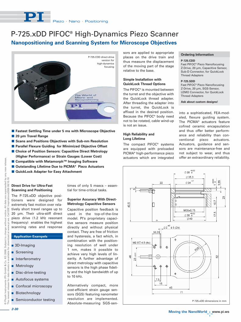
2-30
©P
hys
ikIn
stru
men
te(P
I)G
mb
H&
Co
.KG
2008
.Su
bje
ctto
chan
ge
wit
ho
ut
no
tice
.All
dat
aar
esu
per
sed
edb
yan
yn
ewre
leas
e.T
he
new
est
rele
ase
for
dat
ash
eets
isav
aila
ble
for
do
wn
load
atw
ww
.pi.w
s.C
at12
0EIn
spir
atio
ns2
009
08/1
0.18
Piezo • Nano • Positioning
Direct Drive for Ultra-Fast
Scanning and Positioning
The P-725.xDD objective posi-tioners were designed forextremely fast motion over rela-tively short travel ranges up to20 μm. Their ultra-stiff directpiezo drive (1.2 kHz resonantfrequency) enables the highestscanning rates and response
times of only 5 msecs – essen-tial for time-critical tasks.
Superior Accuracy With Direct-
Metrology Capacitive Sensors
Capacitive position feedback isused in the top-of-the-linemodel. PI's proprietary capaci-tive sensors measure positiondirectly and without physicalcontact. They are free of frictionand hysteresis, a fact which, incombination with the position-ing resolution of well under1 nm, makes it possible toachieve very high levels of lin-earity. A further advantage ofdirect metrology with capacitivesensors is the high phase fideli-ty and the high bandwidth of upto 10 kHz.
Alternatively compact, morecost-efficient strain gauge sen-sors (SGS) featuring nanometerresolution are implemented.Absolute-measuring SGS-sen-
sors are applied to appropriateplaces on the drive train andthus measure the displacementof the moving part of the stagerelative to the base.
Simple Installation with
QuickLock Thread Options
The PIFOC® is mounted betweenthe turret and the objective withthe QuickLock thread adapter.After threading the adapter intothe turret, the QuickLock isaffixed in the desired position.Because the PIFOC® body neednot to be rotated, cable wind-upis not an issue.
High Reliability and
Long Lifetime
The compact PIFOC® systemsare equipped with preloadedPICMA® high-performance piezoactuators which are integrated
into a sophisticated, FEA-mod-eled, flexure guiding system.The PICMA® actuators featurecofired ceramic encapsulationand thus offer better perform-ance and reliability than con-ventional piezo actuators.Actuators, guidance and sen-sors are maintenance-free andnot subject to wear, and thusoffer an extraordinary reliability.
� Fastest Settling Time under 5 ms with Microscope Objective
� 20 μm Travel Range
� Scans and Positions Objectives with Sub-nm Resolution
� Parallel Flexure Guiding for Minimized Objective Offset
� Choice of Position Sensors: Capacitive Direct Metrology
(Higher Performance) or Strain Gauges (Lower Cost)
� Compatible with Metamorph™ Imaging Software
� Outstanding Lifetime Due to PICMA® Piezo Actuators
� QuickLock Adapter for Easy Attachment
P-725.xDD PIFOC® High-Dynamics Piezo ScannerNanopositioning and Scanning System for Microscope Objectives
Ordering Information
P-725.CDD
Fast PIFOC® Piezo NanofocusingZ-Drive, 20 μm, Capacitive Sensor,Sub-D Connector, for QuickLockThread Adapters
P-725.SDD
Fast PIFOC® Piezo NanofocusingZ-Drive, 20 μm, SGS-Sensor,LEMO Connector, for QuickLockThread Adapters
Ask about custom designs!
Application Exampels
� 3D-Imaging
� Screening
� Interferometry
� Metrology
� Disc-drive-testing
� Autofocus systems
� Confocal microscopy
� Biotechnology
� Semiconductor testing
P-725.CDD direct-driveversion for
high-dynamicsfocusing
P-725.xDD dimensions in mm

2-31
Piezo • Nano • Positioning
Piezo Flexure Stages /High-Speed Scanning Systems
Nanopositioning / Piezoelectrics
Linear Actuators & Motors
Fast Steering Mirrors /Active Optics
Piezo Drivers /Servo Controllers
Piezoelectrics in Positioning
Nanometrology
Micropositioning
Linear
Vertical & Tip/Tilt
2- and 3-Axis
6-Axis
Single-Channel
Multi-Channel
Modular
Accessories
Index
Model P-725.CDD P-725.SDD Units Tolerance
Active axes Z Z
Motion and positioning
Integrated sensor Capacitive SGS
Open-loop travel, -20 to +120 V 20 20 μm min. (+20 %/-0 %)
Closed-loop travel 20 20 μm calibrated
Open-loop resolution 0.2 0.2 nm typ.
Closed-loop resolution 0.2 0.2 nm typ.
Linearity, closed-loop 0.04 0.5 % typ.
Repeatability ±1.5 ±5 nm typ.
Runout θX, θY 2 2 μrad typ.
Crosstalk in X, Y 150 150 nm typ.
Mechanical properties
Stiffness in motion direction 1.5 1.5 N/μm ±20 %
Unloaded resonant frequency 1180 1180 Hz ±20 %
Resonant frequency @ 200 g 450 450 Hz ±20 %
Push/pull force capacity in motion direction 100 / 20 100 / 20 N Max.
Drive properties
Ceramic type PICMA® P-887 PICMA® P-887
Electrical capacitance 3.1 3.1 μF ±20 %
Dynamic operating current coefficient 19.4 19.4 μA/(Hz • μm) ±20 %
Miscellaneous
Operating temperature range -20 to 80 -20 to 80 °C
Material Aluminum Aluminum
Mass 0.21 0.2 kg ±5 %
Cable length 1.5 1.5 m ±10 mm
Sensor / voltage connection Sub-D Special LEMO
Recommended controllerE-610 servo controller / amplifier (p. 2-110), E-625 servo controller, bench-top (p. 2-114), E-665 high-power servo controller, bench-top (p. 2-116)Single-channel digital controller: E-753 (bench-top) (p. 2-108)

2-32
©P
hys
ikIn
stru
men
te(P
I)G
mb
H&
Co
.KG
2008
.Su
bje
ctto
chan
ge
wit
ho
ut
no
tice
.All
dat
aar
esu
per
sed
edb
yan
yn
ewre
leas
e.T
he
new
est
rele
ase
for
dat
ash
eets
isav
aila
ble
for
do
wn
load
atw
ww
.pi.w
s.C
at12
0EIn
spir
atio
ns2
009
08/1
0.18
Piezo • Nano • Positioning
The P-726 PIFOC® Nanofocus-ing system was developed toachieve the fastest possiblestepping time with the heavy,high-numerical-aperture objec-tives used in many of today’shigh-resolution microscopyapplications. Its extremely stiffdesign offers excellent settlingtime and scanning frequencyvalues even when objectives ofseveral hundred grams aremoved. High stiffness is
achieved with the rotationallysymmetric arrangement ofmultiple piezo drives and theoptimized design of the flexureand lever elements, whichassure the excellent guidingaccuracy and dynamics.
Furthermore, like other mem-bers of the PIFOC® family, theP-726 is equipped with directmetrology capacitive positionsensors that allow resolutionsfar below one nanometer.
Direct Metrology with
Capacitive Sensors for Highest
Stability and Accuracy
PI's proprietary capacitive posi-tion sensors measure the actu-al motion of the moving partrelative to the stationary base(direct metrology). Errors in thedrive train, actuator, lever armor in guiding system do notinfluence the measurements.The result is exceptional
motion linearity, higher long-term stability and a stiffer,more-responsive servo loop,because external influencesare immediately recognized bythe sensor. Due to this sensorprinciple, the P-726 features aresolution of under 0.4 nm inclosed-loop and a linearity of0.02 %.
Simple Installation with
QuickLock Thread Options
The PIFOC® is mounted be-tween the turret and theobjective with the QuickLockthread adapter. After threadingthe adapter into the turret, theQuickLock is affixed in thedesired position. Because thePIFOC® body need not to berotated, cable wind-up is not anissue.
Ceramic Insulated Piezo
Actuators Provide Long
Lifetime
Highest possible reliability isassured by the use of award-winning PICMA® multilayerpiezo actuators. PICMA® actua-tors are the only actuators onthe market with ceramic-only
insulation, which makes themresistant to ambient humidityand leakage-current failures.They are thus far superior toconventional actuators in relia-bility and lifetime.
P-726 PIFOC® High-Load Objective ScannerHigh-Dynamic Piezo Z Scanner for Heavy Objectives
Application Examples
� 3-D Imaging
� Screening
� Autofocus systems
� Microscopy
� Confocal microscopy
� Surface analysis
� Wafer inspection
Ordering Information
P-726.1CD
High-Dynamics PIFOC® PiezoNanofocusing Z-Drive, 100 μm,Capacitive Sensor
QuickLock Thread Adapter as
Accessories:
P-726.04
P-726 PIFOC® Thread AdapterM28 x 0.75
P-726.05
P-726 PIFOC® Thread AdapterM32 x 0.75
P-726.06
P-726 PIFOC® Thread AdapterM26 x 1/36"
P-726.11
P-726 PIFOC® Thread AdapterM25 x 0.75
P-726.12
P-726 PIFOC® Thread AdapterW0.8 x 1/36"
Ask about custom designs!
� High-Dynamics Positioning and Scanning for Large Objectives
� 1120 Hz Resonant Frequency, 560 Hz with 210 g Load
� Typical Settling Time about 6 ms
� Travel Range 100 μm
� Direct-Metrology Capacitive Sensors for Best Linearity,
Stability and Control Dynamics
� Resolution to 0.3 nm
� Frictionless, High-Precision Flexure Guiding System for Better
Focus Stability
High-dynamics P-726 PIFOC®
for large microscope objectivesover 60 mm in length
P-726 dimensions in mm with P-726.05 M32 QuickLock adapter

2-33
Piezo • Nano • Positioning
Piezo Flexure Stages /High-Speed Scanning Systems
Nanopositioning / Piezoelectrics
Linear Actuators & Motors
Fast Steering Mirrors /Active Optics
Piezo Drivers /Servo Controllers
Piezoelectrics in Positioning
Nanometrology
Micropositioning
Linear
Vertical & Tip/Tilt
2- and 3-Axis
6-Axis
Single-Channel
Multi-Channel
Modular
Accessories
Index
Technical Data
P-726.1CD Tolerance
Active axes Z
Motion and positioning
Integrated sensor Capacitive, direct metrology
Closed-loop travel 100 μm calibrated
Closed-loop resolution 0.4 nm typ.
Open-loop resolution 0.3 nm typ.
Linearity, closed-loop 0.02 % typ.
Repeatability ±3 nm typ.
Runout �X, �Y ±5 μrad typ.
Crosstalk X, Y 50 nm typ.
Mechanical properties
Stiffness in motion direction 3.4 N/μm ±20 %
Unloaded resonant frequency 1120 Hz ±20 %
Resonant frequency under load 560 Hz @ 210 g ±20 %
Resonant frequency under load 480 Hz @ 310 g ±20 %
Push/pull force capacity in motion direction 100 / 50 N Max.
Drive properties
Piezo ceramic type PICMA® P-885
Electrical capacitance 6 μF ±20 %
Dynamic operating current coefficient 7.5 μA/(Hz • μm) ±20 %
Miscellaneous
Operating temperature range -20 to 80 °C
Material Aluminum, steel
Dimensions Diameter: 65 mm, Height: 50.7 mm
Max. objective diameter M32
Mass 575 g ±5 %
Cable length 1.5 m ±10 mm
Sensor / voltage connection Sub-D Special
Recommended controller / amplifier Single-channel digital controller:E-753 (bench-top) (p. 2-108)E-625 bench-top controller (p. 2-114),E-665 high-power bench-top controller (p. 2-116)E-500 modular piezo controller system (p. 2-142)with E-505 high-power amplifier module (p. 2-147)and E-509 servo-controller (p. 2-152)
System properties
System configuration E-500 modular piezo controllersystem with E-505 high-power amplifier moduleand E-509 servo-controller310 g load (objective mass)
Closed-loop amplifier bandwidth, 130 Hzsmall signal, 10 μm
Closed-loop amplifier bandwidth, 70 Hzlarge signal
P-726 QuickLock thread adapter exploded viewwith P-726 PIFOC® (mounting tools included)
P-726 settling time under load
Knurled Ring
Microscope Turret
Turret Ring
PIFOC®
Objective Ring
Objective

2-34
©P
hys
ikIn
stru
men
te(P
I)G
mb
H&
Co
.KG
2008
.Su
bje
ctto
chan
ge
wit
ho
ut
no
tice
.All
dat
aar
esu
per
sed
edb
yan
yn
ewre
leas
e.T
he
new
est
rele
ase
for
dat
ash
eets
isav
aila
ble
for
do
wn
load
atw
ww
.pi.w
s.C
at12
0EIn
spir
atio
ns2
009
08/1
0.18
Piezo • Nano • Positioning
P-737 PIFOC® Specimen-Focusing Z StageLow-Profile, Long-Range Piezo Z Nanopositioner for Microscopy Samples
PIFOC® P-737 high-speed verti-cal positioning systems aredesigned for use with XYmicroscopy stages–OEM man-ual stages as well as aftermar-ket motorized stages.
While the XY stage positionsthe sample, the piezo-actuator-based P-737 moves the samplealong the optical axis to quicklyand precisely adjust the focus.Vertical stepping with an accu-racy in the nanometer rangetakes only a few milliseconds.
The large aperture is designedto accommodate a variety ofspecimen holders includingslides or multiwell plates.
High-Speed Z Steps for Fast
Focus Control and Z Stack
Acquisition
The immediate response of thesolid-state piezo drives enablesrapid Z-steps with typically10 to 20 times faster step &settle times than classical step-per motor drives. This leads tohigher image acquisition speedand throughput.
Closed-Loop Position Control
for High-Precision and
Stability
For high stability and repeata-bility, P-737 stages areequipped with position feed-back. High-resolution, fast-responding, strain gauge sen-sors (SGS) are applied toappropriate locations on thedrive train and provide a high-bandwidth, nanometer-preci-sion position feedback signal tothe controller. The sensors areconnected in a full-bridge con-figuration to eliminate thermaldrift, and assure optimal posi-tion stability in the nanometerrange.
Excellent Guiding Accuracy
Flexures optimized with FiniteElement Analysis (FEA) areused to guide the stage. FEAtechniques are used to give thedesign the highest possiblestiffness in, and perpendicularto, the direction of motion, andto minimize linear and angularrunout. Flexures allow ex-tremely high-precision motion,no matter how minute, as they
are completely free of play andfriction.
Ceramic Insulated Piezo
Actuators Provide Long
Lifetime
Highest possible reliability isassured by the use of award-winning PICMA® multilayerpiezo actuators. PICMA® actua-tors are the only actuators onthe market with ceramic-onlyinsulation, which makes themresistant to ambient humidityand leakage-current failures.They are thus far superior toconventional actuators in relia-bility and lifetime.
� High-Speed Piezo Z Motion with Travel Ranges to 250 μm
(Up to 500 μm on Request)
� Nanometer Resolution
� Large Clear Aperture to Accommodate Specimen Holders
� Perfect Mechanical Fit with XY OEM Manual or
Motorized Stages
� Response Times in the Millisecond Range
Application Examples
� Fluorescence microscopy
� Confocal microscopy
� Biotechnology
� Autofocus systems
� 3D Imaging
� Medical technology
Ordering Information
P-737.1SL
PIFOC® Nanofocusing Z-Stagefor Microscope Sample Holder,100 μm, SGS, LEMO Connector,for Märzhäuser Microscope Stages
P-737.2SL
PIFOC® Nanofocusing Z-Stagefor Microscope Sample Holder,250 μm, SGS, LEMO Connector,for Märzhäuser Microscope Stages
Versions with up to 500 μm travel
or with direct-measuring, high-
resolution capacitive sensors on
request.
P-737 piezo Z-stage for high-resolution microscopy
�����
���
�����
����
��
�
�����
���
���
���
���
��
��
��
����
���
AA
� ���
�����
���
���
�
��
���
��
��
�
��
���
�
���
�����
���
����
����
����
����
����
�������������������� �����!� "!����
�
�
��
#�#
�
�
�$ P-737 dimensions in mm

2-35
Piezo • Nano • Positioning
Piezo Flexure Stages /High-Speed Scanning Systems
Nanopositioning / Piezoelectrics
Linear Actuators & Motors
Fast Steering Mirrors / Active Optics
Piezo Drivers / Servo Controllers
Piezoelectrics in Positioning
Nanometrology
Micropositioning
Linear
Vertical & Tip/Tilt
2- and 3-Axis
6-Axis
Single-Channel
Multi-Channel
Modular
Accessories
Index
Technical Data
Model P-737.1SL P-737.2SL Units Tolerance
Active axes Z Z
Motion and positioning
Integrated sensor SGS SGS
Open-loop travel, -20 to +120 V 150 280 μm min. (+20 %/-0 %)
Closed-loop travel 100 250 μm
Open-loop resolution 0.8 1 nm typ.
Closed-loop resolution 2.5 4 nm typ.
Linearity, closed-loop 0.2 0.2 % typ.
Repeatability 6 12 nm typ.
Runout X ±36 ±36 μrad typ.
Runout Y ±36 ±140 μrad typ.
Mechanical properties
Unloaded resonant frequency 270 210 Hz ±20 %
Resonant frequency @ 100 g 230 180 Hz ±20 %
Resonant frequency @ 200 g 210 155 Hz ±20 %
Push/pull force capacity in motion direction 50 / 20 50 / 20 N Max.
Drive properties
Ceramic type PICMA® P-885 PICMA® P-885
Electrical Capacitance 6.3 9.3 μF ±20 %
Dynamic operating current coefficient 7.9 4.6 μA/(Hz • μm) ±20 %
Miscellaneous
Operating temperature range -20 to 80 -20 to 80 °C
Material Aluminum Aluminum
Dimensions 220.5 x 138 x 27.3 220.5 x 138 x 27.3 mm
Mass 0.7 0.7 kg ±5 %
Cable length 2 2 m ±10 mm
Sensor / voltage connection LEMO LEMO
System properties
System configuration E-500 System with E-500 System with
E-503 amplifier (6 W) E-503 amplifier (6 W)
E-509 servo module E-509 servo module
Closed-loop amplifier bandwidth, small signal 60 30 Hz typ.
Settling time (10 % step width) 24 30 ms typ.
Recommended controller / amplifierSingle-channel: E-610 servo controller / amplifier (p. 2-110), E-625 servo controller, bench-top (p. 2-114), E-665 powerful servo controller, bench-top (p. 2-116)
The P-737 piezo Z-stage (shown withmultiwell plate) is compatible with
motorized microscope XY stages likethe one shown from Märzhäuser
Instead of moving the sample, it is also possible to move the objective. The P-725 PIFOC® Objective Scanner offers travel
ranges over 400 μm with nanometer resolution and response times in the millisecond range

2-36
© P
hys
ik In
stru
men
te (
PI)
Gm
bH
& C
o. K
G 2
008.
Su
bje
ct t
o c
han
ge
wit
ho
ut
no
tice
. All
dat
a ar
e su
per
sed
ed b
y an
y n
ew r
elea
se.
Th
e n
ewes
t re
leas
e fo
r d
ata
shee
ts is
ava
ilab
le f
or
do
wn
load
at
ww
w.p
i.ws.
Cat
120E
Insp
irat
ion
s200
9 08
/10.
18
Piezo • Nano • Positioning
P-611.Z Piezo Z-StageCompact Nanopositioner
P-611 Z stages are piezo-basednanopositioning systems with100 μm closed-loop travelrange featuring a compact foot-print of only 44 x 44 mm. Thestages described here are partof the P-611 family of position-ers available in 1- to 3-axis con-figurations. Equipped withceramic-encapsulated piezodrives and a stiff, zero-stiction,zero-friction flexure guidingsystem, all P-611 piezo stagescombine millisecond respon-siveness with nanometric pre ci-sion and extreme reliability.
The P-611.Z versions describedhere are ideally suited for usein applications such as micro -
s copy, auto-focusing and pho-to nics packaging.
Closed-Loop and Open-Loop
Versions
High-resolution, fast-respond-ing, strain gauge sensors (SGS)are applied to appropriate loca-tions on the drive train and pro-vide a high-bandwidth, nano -meter-precision position feed-back signal to the controller.The sensors are connected in afull-bridge configuration to eli -minate thermal drift, and as -sure optimal position stabilityin the nanometer range.
The open-loop models are idealfor applications where fastresponse and very high resolu-tion are essential, but absolutepositioning is not important.They can also be used whenthe position is controlled by anexternal feedback system suchas an interferometer, a PSD(position sensitive diode), CCDchip / image processing sys-
tem, or the eyes and hands ofan operator.
Versatility & Combination with
Motorized Stages
The P-611 family of piezo sta -ges comprises a variety of sin-gle- and multi-axis versions (X,XY, Z, XZ and XYZ) that can beeasily combined with a numberof very compact manual or mo -torized micropositioning sys-tems to form coarse/fine posi-tioners with longer travel ran -ges (see p. 2-20, p. 2-50 ff ).
High Reliability and Long
Lifetime
The compact P-611 systems areequipped with preloadedPICMA® high-performance pie -zo actuators which are integrat-ed into a sophisticated, FEA-modeled, flexure guiding sys-tem. The PICMA® actuators fea-
ture cofired ceramic encapsula-tion and thus offer better per-for mance and reliability thanconventional piezo actuators.Act uators, guidance and sen-sors are maintenance-free andnot subject to wear, and thusoffer an extraordinary reliabili-ty.
Ordering Information
P-611.Z0
Vertical Nanopositioning Stage, 120 μm, No Sensor
P-611.ZS
Vertical Nanopositioning Stage, 100 μm, SGS-Sensor
P-611.ZS dimensions in mm
Application Examples
� Photonics / integratedoptics
� Micromachining
� Micromanipulation
� Semiconductor testing
� Compact: Footprint Only 44 x 44 mm
� Travel Range to 120 μm
� Resolution to 0.2 nm
� Cost-Effective Mechanics/Electronics System Configurations
� Frictionless, High-Precision Flexure Guiding System
� Outstanding Lifetime Due to PICMA® Piezo Actuators
� X, XY, XZ and XYZ Versions also Available
P-611 Z-axis nanopositioning stage, 100 μm closed-loop travel, resolution to 0.2 nm

2-37
Piezo • Nano • Positioning
Piezo Flexure Stages /High-Speed Scanning Systems
Nanopositioning / Piezoelectrics
Linear Actuators & Motors
Fast Steering Mirrors / Active Optics
Piezo Drivers / Servo Controllers
Piezoelectrics in Positioning
Nanometrology
Micropositioning
Linear
Vertical & Tip/Tilt
2- and 3-Axis
6-Axis
Single-Channel
Multi-Channel
Modular
Accessories
Index
Technical Data
Model P-611.ZS P-611. Z0 Unit Tolerance
Active axes Z Z
Motion and positioning
Integrated sensor SGS -
Open-loop travel, -20 to +120 V 120 120 μm min. (+20 %/0 %)
Closed-loop travel 100 - μm
Open-loop resolution 0.2 0.2 nm typ.
Closed-loop resolution 2 - nm typ.
Linearity 0.1 - % typ.
Repeatability <10 - nm typ.
Runout θZ (Z motion) ±5 ±5 μrad typ.
Runout θX (Z motion) ±20 ±20 μrad typ.
Runout θY (Z motion) ±5 ±5 μrad typ.
Mechanical properties
Stiffness 0.45 0.45 N/μm ±20 %
Unloaded resonant frequency 460 460 Hz ±20 %
Resonant frequency @ 30 g 375 375 Hz ±20 %
Resonant frequency @ 100 g 265 265 Hz ±20 %
Push/pull force capacity 15 / 10 15 / 10 N Max.
Drive properties
Ceramic type PICMA® P-885 PICMA® P-885
Electrical capacitance 1.5 1.5 μF ±20 %
Dynamic operating current coefficient 1.9 1.9 μA/(Hz • μm) ±20 %
Miscellaneous
Operating temperature range -20 to 80 -20 to 80 °C
Material Aluminum, steel Aluminum, steel
Dimensions 44 x 44 x 27 44 x 44 x 27 mm
Mass 176 176 g ±5 %
Cable length 1.5 1.5 m ±10 mm
Sensor connector LEMO LEMO
Voltage connection LEMO LEMO
Resolution of PI Piezo Nano positioners is not limited by friction or stiction. Value given is noise equivalent motion with E -503 amplifier (p. 2-146)Recommended controller / amplifierE-610 servo controller / amplifier (p. 2-110), E-625 servo controller, bench-top (p. 2-114), E-665 powerful servo controller, bench-top (p. 2-116), E-660 bench-top foropen-loop systems (p. 2-119)
The settling time of a P-611.Z with a load of 30 g is 26 ms for a10 μm step. Measured with interferometer
The whole P-611 family: X, Z, XY, XZ and XYZ stages
System properties
System Configuration P-611.1S and E-665.SR controller, 30 g load
Amplifier bandwidth, small signal 40 Hz
Settling time (10 % step width) 25 ms

2-38
© P
hys
ik In
stru
men
te (
PI)
Gm
bH
& C
o. K
G 2
008.
Su
bje
ct t
o c
han
ge
wit
ho
ut
no
tice
. All
dat
a ar
e su
per
sed
ed b
y an
y n
ew r
elea
se.
Th
e n
ewes
t re
leas
e fo
r d
ata
shee
ts is
ava
ilab
le f
or
do
wn
load
at
ww
w.p
i.ws.
Cat
120E
Insp
irat
ion
s200
9 08
/10.
18
Piezo • Nano • Positioning
P-612.Z Piezo Z StageCompact Nanopositioning Stage with Aperture
These elevation stages arecost-effective, compact, piezo-based positioning systemswith travel ranges of 100 μm.The space-saving design fea-tures a footprint of only 60 x 60mm. The 20 x 20 mm clearaperture makes them ideallysuited for sample positioningin microscopy. Equipped withPICMA® piezo drives and zero-stiction, zero-friction flexureguiding system, the series pro-
vides nanometer-range reso -lution and millisecond res -ponse time.
Position Servo-Control with
Nanometer Resolution
High-resolution, broadband,strain gauge sensors (SGS) areapplied to appropriate loca-tions on the drive train andmeasure the displacement ofthe moving part of the stagerelative to the base. The SGSsensors assure optimum posi-tion stability in the nanometerrange and fast response.
The open-loop models areideal for applications wherefast response and very highresolution are essential, butabsolute positioning is notimportant. They can also beused when the position is con-trolled by an external sensor
such as an interferometer, aPSD (position sensitive detec-tor), CCD chip / image process-ing system, or the eyes andhands of an operator.
High Reliability and Long
Lifetime
The compact P-612 systemsare equipped with preloadedPICMA® high-performancepiezo actuators which are inte-grated into a sophisticated,FEA-modeled, flexure guidingsystem. The PICMA® actuatorsfeature cofired ceramic encap-sulation and thus provide bet-ter performance and reliabilitythan conventional piezo actua-tors. Actuators, guiding system
and sensors are maintenance-free, not subject to wear andoffer an extraordinary reliabili-ty.
� Travel Range 100 μm
� Resolution to 0.2 nm
� Linearity 0.2 %
� Compact: Footprint 60 x 60 mm
� Very Cost-Effective Controller/Piezomechanics Systems
� Frictionless, High-Precision Flexure Guiding System
� Outstanding Lifetime Due to PICMA® Piezo Actuators
P-612s are available as XY-scanners (P-612.2SL, on the left)and vertical stages (P-612.ZSL, on the right) providing a travel range of 100 μm per axis
Application Examples
� Interferometry
� Scanning microscopy
� Nanopositioning
� Biotechnology
� Quality assurance testing
� Semiconductor fabrication
P-612.ZSL compact nano-elevation stage with a
20 mm x 20 mm clear aperture
Ordering Information
P-612.ZSL
Vertical Nanopositioning Stage, 100 μm, 20 x 20 mm Aperture, SGS-Sensor
P-612.Z0L
Vertical Nanopositioning Stage, 100 μm, 20 x 20 mm Aperture, No Sensor
Settling takes less than 10 ms over the entire travel range in closed-loop operation

2-39
Piezo • Nano • Positioning
Piezo Flexure Stages /High-Speed Scanning Systems
Nanopositioning / Piezoelectrics
Linear Actuators & Motors
Fast Steering Mirrors / Active Optics
Piezo Drivers / Servo Controllers
Piezoelectrics in Positioning
Nanometrology
Micropositioning
Linear
Vertical & Tip/Tilt
2- and 3-Axis
6-Axis
Single-Channel
Multi-Channel
Modular
Accessories
Index
P-612.Z dimensions in mm
Technical Data
Model P-612.ZSL P-612.Z0L Units Tolerance
Active axes Z Z
Motion and positioning
Integrated sensor SGS –
Open-loop travel, -20 to +120 V 110 110 μm min. (+20 %/-0 %)
Closed-loop travel 100 – μm calibrated
Open-loop resolution 0.2 0.2 nm typ.
Closed-loop resolution 1.5 – nm typ.
Linearity, closed-loop 0.2 – % typ.
Repeatability ±4 – nm typ.
Runout θX, θY ±10 ±10 μrad typ.
Crosstalk X, Y ±20 ±20 μm typ.
Mechanical properties
Stiffness in motion direction 0.63 0.63 N/μm ±20 %
Unloaded resonant frequency 490 490 Hz ±20 %
Resonant frequency under load 420 (30 g) 420 (30 g) Hz ±20 %
Load capacity 15 / 10 15 / 10 N Max.
Drive properties
Ceramic type PICMA® P-885 PICMA® P-885
Electrical capacitance 3 3 μF ±20 %
Dynamic operating current coefficient 3.8 3.8 μA/(Hz • μm) ±20 %
Miscellaneous
Operating temperature range -20 to 80 -20 to 80 °C
Material Aluminum Aluminum
Mass 0.28 0.275 kg ±5 %
Cable length 1.5 1.5 m ±10 mm
Sensor / voltage connection LEMO LEMO (no sensor)
System properties
System configuration P-612.ZSL and E-625.SRcontroller, 30 g load
Closed-loop amplifier 110 Hzsmall signal bandwidth
Closed-loop amplifier 80 Hzlarge signal bandwidth
Settling time (10 % step width) 8 ms
Resolution of PI PiezoNanopositioners is notlimited by friction or stic-tion. Value given is noiseequivalent motion with E-503 amplifier. (p. 2-146)Recommended controller /amplifierE-610 servo controller /amplifier card (p. 2-110), E-625 servo-controller,bench-top (p. 2-114), E-665high-power servo-control-ler with display, bench-top(p. 2-116), E-660 bench-topfor open-loop systems (p. 2-119)

© P
hys
ik In
stru
men
te (
PI)
Gm
bH
& C
o. K
G 2
008.
Su
bje
ct t
o c
han
ge
wit
ho
ut
no
tice
. All
dat
a ar
e su
per
sed
ed b
y an
y n
ew r
elea
se.
Th
e n
ewes
t re
leas
e fo
r d
ata
shee
ts is
ava
ilab
le f
or
do
wn
load
at
ww
w.p
i.ws.
Cat
120E
Insp
irat
ion
s200
9 08
/10.
18
Piezo • Nano • Positioning
Z-axis PIHera® systems arecost-efficient piezo nanoposi-tioning stages featuring travelranges up to 400 μm and pro-vide sub-nanometer reso -lution. Despite the increasedtravel ranges, the units areextremely compact and pro-vide sub-nanometer reso -
lution. The long travel range isachieved with a friction-freeand extremely stiff flexure sys-tem, which also offers rapidresponse and excellent guidingaccuracy.
PIHera® piezo nanopositioningstages are also available as X-and XY-stages (see p. 2-22 andp. 2-54).
Nanometer Precision in
Milliseconds
One of the advantages ofPIHera® stages over motor-dri-ven positioning stages is therapid response to inputchanges and the fast and pre-cise settling behavior. The P-622.1CD, for example, can
settle to an accuracy of 10 nmin only 30 msec (other PIstages provide even fasterresponse)!
Superior Accuracy With
Direct-Metrology Capacitive
Sensors
A choice of tasks such as opti-cal path adjustment in interfer-ometry, sample positioning inmicroscopy, precision align-ment or optical trackingrequire the relatively longscanning ranges and nanome-ter precision offered by PIHera®
nanopositioning stages.
PI's proprietary capacitive sen-sors measure position directlyand without physical contact.They are free of friction andhysteresis, a fact which, incombination with the position-ing resolution of well under 1 nm, makes it possible toachieve very high levels of line-arity. A further advantage ofdirect metrology with capaci-tive sensors is the high phasefidelity and the high bandwidthof up to 10 kHz.
Designed for Precision
High stiffness is achieved withthe FEA-optimized design of
the frictionless flexure ele-ments, which assure excellentguiding accuracy and dynam-ics. A straightness and flatnessin the nanometer range isachieved.
Ordering Information
P-620.ZCD
PIHera® Precision VerticalNanopositioning Stage, 50 μm,Capacitive Sensor, Sub-D Connector
P-620.ZCL
PIHera® Precision VerticalNanopositioning Stage, 50 μm,Capacitive Sensor, LEMO Connector
P-621.ZCD
PIHera® Precision VerticalNanopositioning Stage, 100 μm,Capacitive Sensor, Sub-D Connector
P-621.ZCL
PIHera® Precision VerticalNanopositioning Stage, 100 μm,Capacitive Sensor, LEMO Connector
P-622.ZCD
PIHera® Precision VerticalNanopositioning Stage, 250 μm,Capacitive Sensor, Sub-D Connector
P-622.ZCL
PIHera® Precision VerticalNanopositioning Stage, 250 μm,Capacitive Sensor, LEMO Connector
Open-loop versions are available as
P-62x.Z0L
Nanopositioning System Family with Direct Metrology and Long Travel Ranges
P-620.Z – P-622.Z PIHera® Precision Z-Stage
P-620.ZCL, P-621.ZCL and P-622.ZCL (from left ) PIHera® piezo nano-elevationstages, 50 to 400 μm (CD for size comparison)
Application Examples
� Interferometry
� Microscopy
� Nanopositioning
� Biotechnology
� Quality assurance testing
� Semiconductor technology
� Vertical Travel Range 50 to 400 μm
� High-Precision, Cost-Efficient
� Resolution to 0.1 nm
� Direct Metrology with Capacitive Sensors
� 0,02 % Positioning Accuracy
� Frictionless, High-Precision Flexure Guiding System
� Outstanding Lifetime Due to PICMA® Piezo Actuators
� X-, XY-, Z- XYZ-Versionen
� Vacuum-Compatible Versions Available
P-62x.ZCD / .ZCL / .Z0L dimensions in mm
2-40

2-41
Piezo • Nano • Positioning
Piezo Flexure Stages /High-Speed Scanning Systems
Nanopositioning / Piezoelectrics
Linear Actuators & Motors
Fast Steering Mirrors / Active Optics
Piezo Drivers / Servo Controllers
Piezoelectrics in Positioning
Nanometrology
Micropositioning
Linear
Vertical & Tip/Tilt
2- and 3-Axis
6-Axis
Single-Channel
Multi-Channel
Modular
Accessories
Index
PIHera® XYZ combination
Technical Data
Model P-620.ZCD P-621.ZCD P-622.ZCD P-62x.Z0L Units ToleranceP-620.ZCL P-621.ZCL P-622.ZCL Open-loop versions
Active axes Z Z Z Z
Motion and positioning
Integrated sensor Capacitive Capacitive Capacitive –
Open-loop travel, -20 to +120 V 65 140 400 as P-62x.ZCD μm min. (+20 %/-0 %)
Closed-loop travel 50 100 250 – μm
Open-loop resolution 0.1 0.2 0.5 as P-62x.ZCD nm typ.
Closed-loop resolution 0.2 0.3 1 – nm typ.
Linearity 0.02 0.02 0.02 – % typ.
Repeatability ±1 ±1 ±1 – nm typ.
Runout θX, θY) <20 <20 <80 as P-62x.ZCD μrad typ.
Mechanical properties
Stiffness 0.5 0.6 0.24 as P-62x.ZCD N/μm ±20 %
Unloaded resonant frequency 1000 790 360 as P-62x.ZCD Hz ±20 %
Resonant frequency @ 30 g 690 500 270 as P-62x.ZCD Hz ±20 %
Push/pull force capacity 0 / 5 10 / 8 10 / 8 as P-62x.ZCD N Max.
Load capacity 10 10 10 as P-62x.ZCD N Max.
Lateral Force 10 10 10 as P-62x.ZCD N Max.
Drive properties
Ceramic type PICMA® P-883 PICMA® P-885 PICMA® P-885 as P-62x.ZCD
Electrical capacitance 0.7 3 6.2 as P-62x.ZCD μF ±20 %
Dynamic operating current coefficient 1.8 3.8 3.1 as P-62x.ZCD μA/(Hz • μm) ±20 %
Miscellaneous
Operating temperature range -20 to 80 -20 to 80 -20 to 80 -20 to 150 °C
Material Aluminum Aluminum Aluminum Aluminum
Mass 0.12 0.17 0.24 as P-62x.ZCD g ±5 %
Cable length 1.5 1.5 1.5 as P-62x.ZCD m ±10 mm
Sensor / voltage connection Sub-D special Sub-D special Sub-D special LEMO (no sensor)(CD-version) (CD-version) (CD-version)CL-version: CL-version: CL-version:LEMO LEMO LEMO
Recommended controllerCD-Versions: E-610 servo controller / amplifier (p. 2-110), E-625 servo controller, bench-top (p. 2-114), E-665 powerful servo controller, bench-top (p. 2-116)Single-channel digital controller: E-753 (bench-top) (p. 2-108)CL-Versions: Modular piezo controller system E-500 (p. 2-142) with amplifier module E-505 (high performance) (p. 2-147) and E-509 controller (p. 2-152)Open-loop versions: modular piezo controller system E-500 (p. 2-142) with amplifier module E-505 (high performance) (p. 2-147)
System properties
System configuration P-621.ZCD with E-753 digital controllerand 30 g load
Amplifier bandwidth, small signal 25 Hz
Amplifier bandwidth, large signal 25 Hz
Settling time (full travel) 15 ms
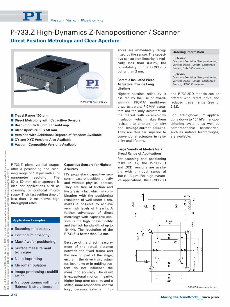
© P
hys
ik In
stru
men
te (
PI)
Gm
bH
& C
o. K
G 2
008.
Su
bje
ct t
o c
han
ge
wit
ho
ut
no
tice
. All
dat
a ar
e su
per
sed
ed b
y an
y n
ew r
elea
se.
Th
e n
ewes
t re
leas
e fo
r d
ata
shee
ts is
ava
ilab
le f
or
do
wn
load
at
ww
w.p
i.ws.
Cat
120E
Insp
irat
ion
s200
9 08
/10.
18
Piezo • Nano • Positioning
P-733.Z piezo vertical stagesoffer a positioning and scan-ning range of 100 μm with sub-nanometer resolution. The 50 x 50 mm clear aperture isideal for applications such asscanning or confocal micro -scopy. Their fast settling time ofless than 10 ms allows highthroughput rates.
Capacitive Sensors for Highest
Accuracy
PI's proprietary capacitive sen-sors measure position directlyand without physical contact.They are free of friction andhysteresis, a fact which, in com-bination with the positioningresolution of well under 1 nm,makes it possible to achievevery high levels of linearity. Afurther advantage of directmetrology with capacitive sen-sors is the high phase fidelityand the high bandwidth of up to10 kHz. The resolution of the P-733.Z is better than 0.3 nm.
Because of the direct measure-ment of the actual distancebetween the fixed frame andthe moving part of the stage,errors in the drive train, actua-tor, lever arm or in guiding sys-tem do not influence the measur ing accuracy. The resultis exceptional motion linearity,higher long-term stability and astiffer, more-responsive controlloop, because external influ-
ences are immediately recog-nized by the sensor. The capaci-tive sensor non-linearity is typi-cally less than 0.03 %, therepeatability of the P-733.Z isbetter than 2 nm.
Ceramic Insulated Piezo
Actuators Provide Long
Lifetime
Highest possible reliability isassured by the use of award-winning PICMA® multilayerpiezo actuators. PICMA® actua-tors are the only actuators onthe market with ceramic-onlyinsulation, which makes themresistant to ambient humidityand leakage-current failures.They are thus far superior toconventional actuators in relia-bility and lifetime.
Large Variety of Models for a
Broad Range of Applications
For scanning and positioningtasks in XY, the P-733.2CD and .3CD versions are availa-ble with a travel range of 100 x 100 μm. For high-dynam-ics applications, the P-733.2DD
and P-733.3DD models can beoffered with direct drive andreduced travel range (see p. 2-62).
For ultra-high-vacuum applica-tions down to 10-9 hPa, nanopo-sitioning systems as well ascomprehensive accessories,such as suitable feedthroughs,are available.
P-733.Z High-Dynamics Z-Nanopositioner / ScannerDirect Position Metrology and Clear Aperture
P-733.Z dimensions in mm
P-733.ZCD Piezo Z-Stage
� Travel Range 100 μm
� Direct Metrology with Capacitive Sensors
� Resolution to 0.3 nm, Closed-Loop
� Clear Aperture 50 x 50 mm
� Versions with Additional Degrees of Freedom Available
� XY and XYZ Versions Also Available
� Vacuum-Compatible Versions Available
Ordering Information
P-733.ZCD
Compact Precision NanopositioningVertical Stage, 100 μm, CapacitiveSensor, Sub-D Connector
P-733.ZCL
Compact Precision NanopositioningVertical Stage, 100 μm, CapacitiveSensor, LEMO Connector
Application Examples
� Scanning microscopy
� Confocal microscopy
� Mask / wafer positioning
� Surface measurementtechnique
� Nano-imprinting
� Micromanipulation
� Image processing / stablili-zation
� Nanopositioning with highflatness & straightness
2-42

2-43
Piezo • Nano • Positioning
Piezo Flexure Stages /High-Speed Scanning Systems
Nanopositioning / Piezoelectrics
Linear Actuators & Motors
Fast Steering Mirrors / Active Optics
Piezo Drivers / Servo Controllers
Piezoelectrics in Positioning
Nanometrology
Micropositioning
Linear
Vertical & Tip/Tilt
2- and 3-Axis
6-Axis
Single-Channel
Multi-Channel
Modular
Accessories
Index
Technical Data
Model P-733.ZCD Tolerance
P-733.ZCL
Active axes Z
Motion and positioning
Integrated sensor Capacitive
Open-loop travel, -20 to +120 V 115 μm min. (+20 %/-0 %)
Closed-loop travel 100 μm
Open-loop resolution 0.2 nm typ.
Closed-loop resolution 0.3 nm typ.
Linearity 0.03 % typ.
Repeatability <2 nm typ.
Rotation around Z <10 μrad typ.
Rotation around X <5 μrad typ.
Rotation around Y <5 μrad typ.
Mechanical properties
Stiffness 2.5 N/μm ±20 %
Unloaded resonant frequency 700 Hz ±20 %
Resonant frequency @ 120 g 530 Hz ±20 %
Resonant frequency @ 200 g 415 Hz ±20 %
Push/pull force capacity 50 / 20 N Max.
Drive properties
Ceramic type PICMA® P-885
Electrical capacitance 6 μF ±20 %
Dynamic operating current coefficient 7.5 μA/(Hz • μm) ±20 %
Miscellaneous
Operating temperature range 20 to 80 °C
Material Aluminum
Dimensions 100 x 100 x 25 mm
Mass 580 g ±5 %
Cable length 1,5 m ±10 mm
Sensor connection Sub-D special (CD-version); 2x LEMO (CL-version)
Voltage connection Sub-D special (CD-version); 1 x LEMO (CL-version)
Step response of the P-733.ZCD. Settling time is in the 10 ms range
System properties
System configuration E-500 modular system with E-503 amplifier and E-509 sensor module; 20 g load
Amplifier bandwidth, small signal 96 Hz
Settling time (10 % step width) 8 ms
Dynamic Operating Current Coefficient in μA per Hzand mrad. Example: Sinusoidal scan of 10 μm at 10 Hzrequires approximately 3 mA drive current. Recommended controller One channel: E-610 controller / amplifier (p. 2-110), E-625 bench-top controller (p. 2-114), E-621 modularcontroller (p. 2-160)Multi-channel: modular piezo controller system E-500(p. 2-142) with amplifier module E-503 (three channels)(p. 2-146) or E-505 (1 per axis, high-power) (p. 2-147)and E-509 controller (p. 2-152)Single-channel digital controller: E-753 (bench-top) (p. 2-108)

2-44
© P
hys
ik In
stru
men
te (
PI)
Gm
bH
& C
o. K
G 2
008.
Su
bje
ct t
o c
han
ge
wit
ho
ut
no
tice
. All
dat
a ar
e su
per
sed
ed b
y an
y n
ew r
elea
se.
Th
e n
ewes
t re
leas
e fo
r d
ata
shee
ts is
ava
ilab
le f
or
do
wn
load
at
ww
w.p
i.ws.
Cat
120E
Insp
irat
ion
s200
9 08
/10.
18
Piezo • Nano • Positioning
P-541.Z Piezo Z and Z/Tip/Tilt StagesLow Profile, Large Aperture
Low Profile, Optimized for
Microscopy Applications
The P-541 Z stages and Z/tip/tiltstages are for ideal alignment,nano-focusing or metrologytasks in the nanometer range.They feature a very low profileof 16.5 mm, a large 80 x 80 mmaperture, and offer highly accu-rate motion with sub-nanome-ter resolution.
A variety of P-541 XY scanningstages with the same footprintare also available (see p. 2-60).Due to the low-profile design,the stages can easily be inte-grated in high-resolutionmicro scopes.
Choice of Position Sensors
PI's proprietary capacitive sen-sors measure position directlyand without physical contact.They are free of friction andhysteresis, a fact which, incom bination with the position-ing resolution of well under 1 nm, makes it possible toachieve very high levels of lin-earity. A further advantage ofdirect metrology with capaci-tive sensors is the high phasefidelity and the high bandwidthof up to 10 kHz.
Alternatively, economicalstrain gauge sensors are avail-able. PI uses a bridge configu-ration to eliminate thermaldrift, and assure optimal posi-tion stability in the nanometerrange.
Active and Passive Guidance
for Nanometer Flatness and
Straightness
Flexures optimized with FiniteElement Analysis (FEA) arecompletely free of play andfriction to allow extremelyhigh-precision motion. TheFEA techniques also optimizestraightness and flatness andprovide for the highest possi-ble stiffness in, and perpendi-cular to, the direction ofmotion.
Due to the parallel-kinematicsdesign there is only one com-mon moving platform for allaxes, minimizing mass, en -abling identical dynamic be -haviour and eliminiating cumu-lative errors. Parallel kinemat-ics also allows for a more com-pact construction and fasterresponse compared to stackedor nested designs.
Ceramic Insulated Piezo
Actuators Provide Long
Lifetime
Highest possible reliability isassured by the use of award-winning PICMA® multilayerpiezo actuators. PICMA® actua-tors are the only actuators onthe market with ceramic-onlyinsulation, which makes themresistant to ambient humidityand leakage-current failures.They are thus far superior toconventional actuators in relia-bility and lifetime.
Ordering Information
P-541.ZCD
Vertical Nanopositioning Stage withLarge Aperture, 100 μm, DirectMetrology, Capacitive Sensors
P-541.TCD
Vertical Tip / Tilt NanopositioningStage with Large Aperture, 100 μm / 1 mrad, Parallel Metrology,Capacitive Sensors
P-541.ZSL
Vertical Nanopositioning Stage withLarge Aperture, 100 μm, StrainGauge Sensors
P-541.TSL
Vertical Tip / Tilt NanopositioningStage with large Aperture, 100 μm,Strain Gauge Sensors
P-541.Z dimensions in mm
� Low Profile for Easy Integration: 16.5 mm; 80 x 80 mm
Clear Aperture
� Vertical and Z/Tip/Tilt Stages
� 100 μm Travel Range, 1 mrad Tilt
� Parallel-Kinematics / Metrology for Enhanced Responsiveness
/ Multi-Axis Precision
� Choice of Sensors: Strain Gauge (Lower Cost) or Capacitive
Sensors (Higher Performance)
� Outstanding Lifetime Due to PICMA® Piezo Actuators
� Combination with Long-Travel M-686 Microscopy Stages
Application Examples
� Scanning microscopy
� Mask / wafer positioning
� Interferometry
� Metrology
� Biotechnology
� Micromanipulation
P-541 series nanopositioning Z-stages and Z-tip/tilt stages offer travel ranges of100 μm with sub-nanometer resolution. They feature a very low profile of
16.5 mm and a large 80 x 80 mm aperture. Versions with strain gauge and capacitive position feedback sensors are available

2-45
Piezo Flexure Stages /High-Speed Scanning Systems
Nanopositioning / Piezoelectrics
Linear Actuators & Motors
Fast Steering Mirrors / Active Optics
Piezo Drivers / Servo Controllers
Piezoelectrics in Positioning
Nanometrology
Micropositioning
Linear
Vertical & Tip/Tilt
2- and 3-Axis
6-Axis
Single-Channel
Multi-Channel
Modular
Accessories
Index
Technical Data
Models P-541.ZCD P-541.TCD* P-541.ZSL P-541.TSL P-541.T0L* P-541.Z0L Units Tolerane
Active axes Z Z, θX, θY Z Z, θX, θY Z Z, θX, θY
Motion and positioning
Integrated sensor Capacitive Capacitive SGS SGS Open-loop Open-loop
Open-loop Z-travel, -20 to +120 V 150 150 150 150 150 150 μm min.
(+20 %/0 %)
Open-loop tip/tilt angle, -20 to +120 V – ±0.6 – ±0.6 – ±0.6 mrad min. (+20 %/0 %)
Closed-loop Z-travel 100 100 100 100 – – μm
Closed-loop tip/tilt angle – ±0.4 – ±0.4 – – mrad
Open-loop Z-resolution 0.2 0.2 0.2 0.2 0.2 0.2 nm typ.
Open-loop tip/tilt angle resolution – 0.001 – 0.001 – 0.001 μrad typ.
Closed-loop Z-resolution 0.5 0.5 2.5 2.5 – – nm typ.
Closed-loop tip/tilt resolution – 0.002 – 0.002 – – μrad typ.
Linearity Z, θX, θY 0.03 0.03 0.2 0.2 – – % typ.
Repeatability Z <2 <2 <10 <10 – – nm typ.
Repeatability θX, θY – 0.01 – 0.05 – – μrad typ.
Runout θX, θY <±5 <±5 <±5 <±5 <±5 <±5 μrad typ.
Mechanical properties
Stiffness Z 0.8 0.8 0.8 0.8 0.8 0.8 N/μm ±20 %
Unloaded resonant frequency (Z) 410 410 410 410 410 410 Hz ±20 %
Unloaded resonant frequency (θX, θY) – 330 – 330 – 330 Hz ±20 %
Resonant frequency @ 200 g (Z) 250 250 250 250 250 250 Hz ±20 %
Resonant frequency @ 200 g (θX, θY) – 270 – 270 – 270 Hz ±20 %
Push/pull force capacity 50 / 20 50 / 20 50 / 20 50 / 20 50 / 20 50 / 20 N Max.
Drive properties
Ceramic type PICMA® PICMA® PICMA® PICMA® PICMA® PICMA®
P-885 P-885 P-885 P-885 P-885 P-885
Electrical capacitance 6.3 6.3 6.3 6.3 6.3 6.3 μF ±20 %
Dynamic operating current coefficient 7.9 7.9 7.9 7.9 7.9 7.9 μA / (Hz • μm) ±20 %
Miscellaneous
Operating temperature range 20 to 80 20 to 80 20 to 80 20 to 80 20 to 80 20 to 80 °C
Material Aluminum Aluminum Aluminum Aluminum Aluminum Aluminum
Mass 750 750 730 730 700 700 g ±5 %
Cable length 1.5 1.5 1.5 1.5 1.5 1.5 m ±10 mm
Sensoranschluss Sub-D Sub-D LEMO 3 x LEMO – –
Special Special
Voltage connection Sub-D Sub-D LEMO 3 x LEMO LEMO 3 x LEMO
Special Special
*Parallel kinematics design; the maximum displacement for translation and tilt motion cannot be achieved at the same timeResolution of PI Piezo Nanopositioners is not limited by friction or stiction. Value given is noise equivalent motion with E-503 (p. 2-146) or E-710 controller (p. 2-128).Recommended controller / amplifierSingle-channel (1 per axis): E-610 servo controller / amplifier (p. 2-110), E-625 servo controller, bench-top (p. 2-114), E-621 controller module (p. 2-160)Multi-channel: modular piezo controller system E-500 (p. 2-142) with amplifier module E-503 (three channels) (p. 2-146) or E-505 (1 per axis, high-power) (p. 2-147) and E-509 controller (p. 2-152)Single-channel digital controller: E-753 (bench-top) (p. 2-108)Multi-channel digital controllers: E-710 bench-top (p. 2-128), E-712 modular (p. 2-140), E-725 high-power (p. 2-126), E-761 PCI board (p. 2-130)
Piezo • Nano • Positioning
System properties
System configuration P-541.ZCD and E-500 modular system with E-503 amplifier and E-509 sensor module, 20 g load
Amplifier bandwidth, small signal 60 Hz
Settling time (10 % step width) 9 ms
M-686 open-frame stage with P-541 piezo scanner on topmakes an ideal combination for microscopy tasks.
The system height is only 48 mm

2-46
© P
hys
ik In
stru
men
te (
PI)
Gm
bH
& C
o. K
G 2
008.
Su
bje
ct t
o c
han
ge
wit
ho
ut
no
tice
. All
dat
a ar
e su
per
sed
ed b
y an
y n
ew r
elea
se.
Th
e n
ewes
t re
leas
e fo
r d
ata
shee
ts is
ava
ilab
le f
or
do
wn
load
at
ww
w.p
i.ws.
Cat
120E
Insp
irat
ion
s200
9 08
/10.
18
Piezo • Nano • Positioning
High-Dynamics with Large Clear Aperture
P-518, P-528, P-558 Piezo Z/Tip/Tilt Stage
P-5x8 series, Z/tip/tilt nanoposi-tioners / scanners are open-frame, high-resolution, piezo-driven stages providing mo tionto 240 μm and 2.4 mrad withresolutions of up to 0.5 nm and 50 nrad. The 66 x 66 mm clear aperture isideal for transmitted-lightapplications.
XY and XYZ multi-axis ver-sions in the same form factor
are also offered as P-517, P-527(see p. 2-70) models with sixdegrees of freedom are avail-able upon request.
Capacitive Position Sensors
for Higher Accuracy
PI's proprietary capacitive sen-sors measure position directlyand without physical contact.
They are free of friction and hy -steresis, a fact which, in com bi-nation with the positioning res-olution of well under 1 nm,makes it possible to achievevery high levels of linearity. Afurther advantage of directmetrology with capacitive sen-sors is the high phase fidelityand the high bandwidth of upto 10 kHz.
Excellent Guiding Accuracy
Flexures optimized with FiniteElement Analysis (FEA) areused to guide the stage. FEAtechniques are used to give thedesign the highest possiblestiffness in, and perpendicularto, the direction of motion, andto minimize linear and angularrunout. Flexures allow extre -mely high-precision motion, nomatter how minute, as they arecompletely free of play andfriction.
Flatness and Straightness isfurther enhanced by active tra-jectory control: Multi-axisnano positioning systems equi -p ped with both parallel kine-matics and parallel direct me -trology are able to measureplatform position in all degreesof freedom against one com-mon fixed reference. In such
systems, undesirable motionfrom one actuator in the direc-tion of another (cross-talk) isdetected immediately and ac -tively compensated by theservo-loops. This Active Tra -jectory Control Concept cankeep deviation from a trajecto-ry to under a few nanometers,even in dynamic operation.
Higher Precision in Periodic
Motion
The highest dynamic accuracyin scanning applications is
Application Examples
� Metrology
� Interferometry
� Optics
� Lithography
� Scanning microscopy
� Mass storage device testing
� Laser technology
� Micromachining
P-528 Z/tip/tilt piezo nanopositioning system
� 1- and 3-Axis Versions
� Closed-Loop Vertical / Tilt Range to 200 μm / 2 mrad
(Open-Loop to 240 / 2.4)
� Parallel Kinematics / Metrology for Enhanced
Responsiveness & Multi-Axis Precision
� Frictionless, High-Precision Flexure Guiding System
� Outstanding Lifetime Due to PICMA® Piezo Actuators
� Clear Aperture 66 x 66 mm
� Capacitive Sensors for Highest Linearity
Ordering Information
P-558.ZCD
Precision Nanopositioning Z-Stage,50 μm, Direct Metrology, CapacitiveSensors, Sub-D Connector
P-558.ZCL
Precision Nanopositioning Z-Stage,50 μm, Direct Metrology, CapacitiveSensors, LEMO Connector
P-518.ZCD
Precision Nanopositioning Z-Stage,100 μm, Direct Metrology,Capacitive Sensors, Sub-DConnector
P-518.ZCL
Precision Nanopositioning Z-Stage,100 μm, Direct Metrology,Capacitive Sensors, LEMOConnector
P-528.ZCD
Precision Nanopositioning Z-Stage,200 μm, Direct Metrology,Capacitive Sensors, Sub-DConnector
P-528.ZCL
Precision Nanopositioning Z-Stage,200 μm, Direct Metrology,Capacitive Sensors, LEMOConnector
P-558.TCD
Precision Nanopositioning Z/Tip/TiltStage, 50 μm, 0.6 mrad, ParallelMetrology, Capacitive Sensors,Sub-D Connector
P-518.TCD
Precision Nanopositioning Z/Tip/TiltStage, 100 μm, 1.4 mrad, ParallelMetrology, Capacitive Sensors,Sub-D Connector
P-528.TCD
Precision Nanopositioning Z/Tip/TiltStage, 200 μm, 2.4 mrad, ParallelMetrology, Capacitive Sensors,Sub-D Connector
P-558, P-518, P-528 dimensions in mm

2-47
Piezo • Nano • Positioning
Piezo Flexure Stages /High-Speed Scanning Systems
Nanopositioning / Piezoelectrics
Linear Actuators & Motors
Fast Steering Mirrors / Active Optics
Piezo Drivers / Servo Controllers
Piezoelectrics in Positioning
Nanometrology
Micropositioning
Linear
Vertical & Tip/Tilt
2- and 3-Axis
6-Axis
Single-Channel
Multi-Channel
Modular
Accessories
Index
Technical Data
Model P-558.ZCD/ P-558.TCD P-518.ZCD/ P-518.TCD P-528.ZCD/ P-528.TCD Units Tolerance
P-558.ZCL P-518.ZCL P-528.ZCL
Active axes Z Z, �x, �y Z Z, �x, �y Z Z, �x, �y
Motion and positioning
Integrated sensor Capacitive Capacitive Capacitive Capacitive Capacitive Capacitive
Open-loop travel, -20 to +120 V 60 60 140 140 240 240 μm min.
(+20 %/-0 %)
Open-loop tip/tilt angle, -20 to +120 V – ±0.3 mrad – ±0.7 mrad – ±1.2 mrad mrad min. (+20 %/-0 %)
Closed-loop travel 50 50 100 100 200 200 μm
Closed-loop tip/tilt angle – ±0.25 mrad - ±0.5 mrad – ±1 mrad mrad
Open-loop resolution 0.2 0.2 0.2 0.4 0.6 0.6 nm typ.
Open-loop tip/tilt angle resolution – 0.02 – 0.04 – 0.06 μrad typ.
Closed-loop resolution 0.5 0.5 0.8 0.8 1 1 nm typ.
Closed-loop tip/tilt resolution – 0.05 – 0.05 – 0.1 μrad typ.
Linearity �x, �y – 0.03 – 0.03 – 0.03 % typ.
Repeatability ±5 ±5 ±5 ±5 ±10 ±10 nm typ.
Repeatability �x, �y – ±0.03 – ±0.05 – ±0.1 μrad typ.
Runout �z (Z motion) <10 <10 <10 <10 <20 <20 μrad typ.
Runout �x, �y (Z motion) <50 <50 <50 <50 <100 <100 μrad typ.
Mechanical properties
Stiffness 4 4 2.7 2.7 1.5 1.5 N/μm ±20 %
Unloaded resonant frequency (Z) 570 570 500 500 350 350 Hz ±20 %
Unloaded resonant frequency (�x, �y) - 610 - 530 - 390 Hz ±20 %
Resonant frequency @ 30 g in Z 410 410 350 350 210 210 Hz ±20 %
Resonant frequency @ 500 g in X, Y - 430 - 370 - 250 Hz ±20 %
Resonant frequency @2500 g in Z 245 245 200 200 130 130 Hz ±20 %
Resonant frequency @ 2500 g �x, �y - 240 - 190 - 115 Hz ±20 %
Push/pull force capacity 100 / 50 100 / 50 100 / 50 100 / 50 100 / 50 100 / 50 N Max.
Drive properties
Ceramic type PICMA® PICMA® PICMA® PICMA® PICMA® PICMA®
P-885 P-885 P-885 P-885 P-885 P-885
Electrical capacitance 6 6 8.4 8.4 14.8 14.8 μF ±20 %
Dynamic operating current coefficient 15 15 10.5 10.5 9.2 9.2 μA/ ±20%(Hz•μm)
Miscellaneous
Operating temperature range -20 to 80 -20 to 80 -20 to 80 -20 to 80 -20 to 80 -20 to 80 °C
Material Aluminum Aluminum Aluminum Aluminum Aluminum Aluminum
Dimensions 150x150x30 150x150x30 150x150x30 150x150x30 150x150x30 150x150x30 mm
Mass 1380 1380 1400 1400 1420 1420 g ±5 %
Cable length 1.5 1.5 1.5 1.5 1.5 1.5 m ±10 mm
Sensor / voltage connection CD-version: Sub-D CD-version: Sub-D CD-version: Sub-D
Sub-D special Special Sub-D special Special Sub-D special Special
CL-version: CL-version: CL-version:
LEMO LEMO LEMO
Resolution of PI Piezo Nanopositioners is not limited by friction or stiction. Value given is noise equivalent motion with E-503 (p. 2-146) or E-710 controller (p. 2-128)Recommended controllerCD-Versions: Single-channel (1 per axis): E-610 servo controller / amplifier (p. 2-110), E-625 servo controller, bench-top (p. 2-114)Single-channel digital controller: E-753 (bench-top) (p. 2-108)CL-Versions: Single-channel: E-500 modular piezo controller system (p. 2-142) with E-505 (p. 2-147) high-power amplifier module and E-509 servo-controller (p. 2-152)Multi-channel versions: Multi-channel digital controllers: E-710 bench-top (p. 2-128), E-712 modular (p. 2-140), E-725 high-power (p. 2-126), E-761 PCI board (p. 2-130)
made possible by the DDLalgorithm, which is available inPI's modern digital controllers.DDL eliminates tracking errors,improving dynamic linearityand usable bandwidth by up tothree orders of magnitude!
Ceramic Insulated Piezo Actu -
ators Provide Long Lifetime
Highest possible reliability isassured by the use of award-winning PICMA® multilayerpiezo actuators. PICMA® actua-tors are the only actuators on
the market with ceramic-onlyinsulation, which makes themresistant to ambient humidityand leakage-current failures.They are thus far superior toconventional actuators in relia-bility and lifetime.

Piezo • Nano • Positioning
P-732 Piezo Z-Stage with ApertureHigh-Dynamics Nanopositioner / Scanner
� 15 μm Vertical Travel Range
� High Stiffness for Dynamic Operation
� <1 nm Resolution
� Straightness of Travel <10 μrad
� Clear Aperture with 25 mm Diameter
P-915K Vacuum-Compatible Piezo-Z StageHigh-Load, High Dynamics and Large Clear Aperture
� Travel Range 45 μm
� Large Clear Aperture 273 x 273 mm
� Direct Metrology with Capacitive Sensors
� Direct Drive for High Dynamics and Stiffness
� Vacuum Compatible up to 10-6 hPa
� Outstanding Lifetime Due to PICMA® Piezo Actuators
P-915K Low-Profile Piezo Objective ScannerFor High Scanning Frequencies
� Very Low Profile of 15 mm
� Travel Range 75 μm
� Clear Aperture for Objectives with W0.8 x 1/36” Thread
� Frictionless, High-Precision Flexure Guiding System for
Better Focus Stability and Minimized Runout
� Very Low Profile
� Outstanding Lifetime Due to PICMA® Piezo Actuators
P-732.ZC verticalnanopositioning stage
with aperture
The direct-drive P-915KVPZ stage provides high stiffness for fast operation
The P-915KLPZ objective scanner allows high scanning frequencies
Model Active Travel range Resonant frequency Dimensions
axes @ 150 g
P-915KLPZ Z 75 μm 200 Hz 60 x 60 x 15 mmObjective Scanner
Model Travel Resolution Linearity Laod capacity Rotation around
�X, �Y
P-732.ZC 15 μm 0.1 nm 0.03 % 20 N <10 μrad
Model Travel Resolution Push/ Material Dimensions
Pull force
capacity
P-915KVPZ 45 μm 0.3 nm 20 N Stainless Moving platform: Z Stage stell 375 x 375 mm
Clear aperture: 273 x 273 mm
2-48
© P
hys
ik In
stru
men
te (
PI)
Gm
bH
& C
o. K
G 2
008.
Su
bje
ct t
o c
han
ge
wit
ho
ut
no
tice
. All
dat
a ar
e su
per
sed
ed b
y an
y n
ew r
elea
se.
Th
e n
ewes
t re
leas
e fo
r d
ata
shee
ts is
ava
ilab
le f
or
do
wn
load
at
ww
w.p
i.ws.
Cat
120E
Insp
irat
ion
s200
9 08
/10.
18

2-49
Piezo • Nano • Positioning
Piezo Flexure Stages /High-Speed Scanning Systems
Nanopositioning / Piezoelectrics
Linear Actuators & Motors
Fast Steering Mirrors / Active Optics
Piezo Drivers / Servo Controllers
Piezoelectrics in Positioning
Nanometrology
Micropositioning
Linear
Vertical & Tip/Tilt
2- and 3-Axis
6-Axis
Single-Channel
Multi-Channel
Modular
Accessories
Index
N-515K Non-Magnetic Piezo Hexapod6-Axis Precision Positioning System with NEXLINE® Linear Drives
� Travel Ranges 10 mm Linear, 6° Rotation
� Large Clear Aperture Ø 202 mm
� Non-Magnetic
� Nanometer Resolution
� Low-Profile: 140 mm Height Only
� Parallel Kinematics for Enhanced Dynamics and
Better Multi-Axis Accuracy
� Up to 500 N Force Generation
� Self Locking at Rest, No Heat Generation
N-510 High-Force NEXLINE® Z/Tip/Tilt PlatformNanometer Precision for Semiconductor Industry, Wafer Alignment
� Self Locking at Rest, No Heat Generation
� Vacuum Compatible and Non-Magnetic Designs Feasible
� Parallel Kinematics for Enhanced Dynamics and
Better Multi-Axis Accuracy
� NEXLINE® Piezo Walking Drive Free from Wear and Tear
� Load Capacity 200 N
� High Precision with Integrated 5 nm Incremental Sensors +
Picometer Resolution Dithering Mode
N-510K High-Stiffness NEXLINE® Z StageHigh-Precision Positioning, with Capacitive Sensors
� Self Locking at Rest, No Heat Generation
� Hybrid Drive: PiezoWalk® plus PICMA®
� Travel Range: 400 μm Coarse + 40 μm Fine
� 2 μm Closed-Loop Resolution
� Direct Metrology:
One Single Control Loop with Capacitive Sensors
� High Push and Holding Force to 25 N
� Piezo Walking Drive w/o Wear and Tear & Outstanding
Lifetime due to PICMA® Piezo Actuators
6-axis parallel kinematics (Hexapod) with integratedN-215 NEXLINE® high-load actuators, suitable for
applications in strong magnetic fields
Z, tip, tilt nanopositioning platform with3 integrated drives (tripod design)
The N-510KHFS hybrid-drive nanopositioneroffers maximum accuracy for semiconductor
inspection applications
Model Travel range Load capacity Dimensions
N-515KNPH X, Y, Z: 10 mm 50 kg Outer Ø baseplate, 380 mmNEXLINE® θX, θY, θZ: 6° Ø moved platform (top) 300 mmPiezo Hexapod 140 mm height
Model Travel Load capacity Linear velocity Dimensions
N-510 NEXLINE® 1,3 mm 200 N 0.2 mm/s Ø 300 mm (12´´)Z, tip, tilt platform vertical range Clear aperture
10 mrad 250 mmtilt angle
Model Vertical Velocity Bidirectional Load Dimensions
travel repeatability capacity
N-510KHFS 400 μm coarse 1 mm/sec 50 nm 25 N Ø 300 mmHybrid- 40 μm fine (full travel) 68.5 mmFocus System height©
Ph
ysik
Inst
rum
ente
(P
I) G
mb
H &
Co
. KG
200
8. S
ub
ject
to
ch
ang
e w
ith
ou
t n
oti
ce. A
ll d
ata
are
sup
erse
ded
by
any
new
rel
ease
.T
he
new
est
rele
ase
for
dat
a sh
eets
is a
vaila
ble
fo
r d
ow
nlo
ad a
t w
ww
.pi.w
s. C
at12
0E In
spir
atio
ns2
009
08/1
0.18

© P
hys
ik In
stru
men
te (
PI)
Gm
bH
& C
o. K
G 2
008.
Su
bje
ct t
o c
han
ge
wit
ho
ut
no
tice
. All
dat
a ar
e su
per
sed
ed b
y an
y n
ew r
elea
se.
Th
e n
ewes
t re
leas
e fo
r d
ata
shee
ts is
ava
ilab
le f
or
do
wn
load
at
ww
w.p
i.ws.
Cat
120E
Insp
irat
ion
s200
9 08
/10.
18
Piezo • Nano • Positioning
P-611.XZ · P-611.2 XZ & XY NanopositionerCompact 2-Axis Piezo System for Nanopositioning Tasks
P-611 piezo stages are flexure-guided nanopositioning sys-tems featuring a compact foot-print of only 44 x 44 mm. TheXY- and XZ-versions describedhere are part of a family of posi-tioners available in 1 to 3 axisconfigurations. Despite theirsmall dimensions the systemsprovide up to 120 μm travel withsub-nanometer resolution. Theyare ideally suited for planar
positioning tasks such as opti-cal-path length correction ininterferometry, sample position-ing in microscopy or scanningapplications, for autofocus andphotonics applications. Bothversions are available with 100μm travel per axis. Equippedwith ceramic-encapsulatedpiezo drives and a stiff, zero-stiction, zero-friction flexureguiding system, all P-611 piezostages combine millisecondresponsiveness with nanomet-ric precision and extreme relia-bility.
Closed-Loop and Open-Loop
Versions
High-resolution, fast-respond-ing, strain gauge sensors (SGS)are applied to appropriate loca-tions on the drive train and pro-vide a high-bandwidth, nano -meter-precision position feed-
back signal to the controller. Thesensors are connected in a full-bridge configuration to elimi-nate thermal drift, and assureoptimal position stability in thenanometer range.
The open-loop models are idealfor applications where fastresponse and very high reso -lution are essential, butabsolute positioning is notimportant. They can also beused when the position is con-trolled by an external linearposition sensor such as an inter-ferometer, a PSD (position sen-sitive diode), CCD chip / imageprocessing system, or the eyesand hands of an operator.
Versatility & Combination with
Motorized Stages
The P-611 family of piezo stagescomprises a variety of single-
and multi-axis versions (X, XY,Z, XZ and XYZ) that can be eas-ily combined with a number ofvery compact manual or motor-ized micropositioning systemsto form coarse/fine positionerswith longer travel ranges (see p. 2-20, p. 2-36 and p. 2-50).
Application Examples
� Fiber positioning
� Semiconductor testing
� Micromachining
� Micromanipulation
� MEMS fabrication/testing
� Photonics / integratedoptics
Ordering Information
P-611.2S
XY Nanopositioning System, 100 x 100 μm, SGS-Sensor
P-611.20
XY Nanopositioning System, 100 x 100 μm, No Sensor
P-611.XZS
XZ Nanopositioning System, 100 x 100 μm, SGS-Sensor
P-611.XZ0
XZ Nanopositioning System, 100 x 100 μm, No Sensor
P-611 XY- and XZ-nanopositioning systems (from left), 100 μm travel, resolution to 0.2 nm
� Compact: Footprint 44 x 44 mm
� Travel Range to 120 x 120 μm
� Resolution to 0.2 nm
� Cost-Effective Mechanics/Electronics System
Configurations
� Frictionless, High-Precision Flexure Guiding System
� Outstanding Lifetime Due to PICMA® Piezo Actuators
� X, Z and XYZ Versions also Available
The whole P-611 family: X, Z, XY, XZ and XYZ stages
2-50
P-611.2S dimensions in mm

2-51
Piezo • Nano • Positioning
Piezo Flexure Stages /High-Speed Scanning Systems
Nanopositioning / Piezoelectrics
Linear Actuators & Motors
Fast Steering Mirrors / Active Optics
Piezo Drivers / Servo Controllers
Piezoelectrics in Positioning
Nanometrology
Micropositioning
Linear
Vertical & Tip/Tilt
2- and 3-Axis
6-Axis
Single-Channel
Multi-Channel
Modular
Accessories
Index
Technical Data
Models P-611.2S P-611.20 P-611.XZS P-611.XZ0 Units Tolerance
Active axes X, Y X, Y X, Z X, Z
Motion and positioning
Integrated sensor SGS – SGS –
Open-loop travel, -20 to +120 V 120 20 120 120 μm min. (+20 %/0 %)
Closed-loop travel 100 – 100 – μm
Open-loop resolution 0.2 0.2 0.2 0.2 nm typ.
Closed-loop resolution 2 – 2 – nm typ.
Linearity 0.1 – 0.1 – % typ.
Repeatability <10 – <10 – nm typ.
Pitch in X,Y ±5 ±5 ±5 ±5 μrad typ.
Runout θX (Z motion) – – ±10 ±10 μrad typ.
Yaw in X ±20 ±20 ±20 ±20 μrad typ.
Yaw in Y ±10 ±10 – – μrad typ.
Runout θY (Z motion) – – ±10 +/-10 μrad typ.
Mechanical properties
Stiffness 0.2 0.2 0.2 0.2 N/μm ±20 %Z: 0.35 Z: 0.35
Unloaded resonant frequency X: 345; Y: 270 X: 345; Y: 270 X: 365; Z: 340 X: 365; Z: 340 Hz ±20 %
Resonant frequency @ 30 g X: 270; Y: 225 X: 270; Y: 225 X: 280; Z: 295 X: 280; Z: 295 Hz ±20 %
Resonant frequency @ 100 g X: 180; Y: 165 X: 180; Y: 165 X: 185; Z: 230 X: 185; Z: 230 Hz ±20 %
Push/pull force capacity 15 / 10 15 / 10 15 / 10 15 / 10 N Max.in motion direction
Load capacity 15 15 15 15 N Max.
Drive properties
Ceramic type PICMA® P-885 PICMA® P-885 PICMA® P-885 PICMA® P-885
Electrical capacitance 1.5 1.5 1.5 1.5 μF ±20 %
Dynamic operating current coefficient 1.9 1.9 1.9 1.9 μA/(Hz • μm) ±20 %
Miscellaneous
Operating temperature range -20 to 80 -20 to 80 -20 to 80 -20 to 80 °C
Material Aluminum, steel Aluminum, steel Aluminum, steel Aluminum, steel
Dimensions 44 x 44 x 25 44 x 44 x 25 44 x 44 x 34 44 x 44 x 34 mm
Mass 0.235 0.235 0.27 0.27 kg ±5 %
Cable length 1.5 1.5 1.5 1.5 m ±10 mm
Sensor connection LEMO – LEMO –
Voltage connection LEMO LEMO LEMO LEMO
Resolution of PI Piezo Nanopositioners is not limited by friction or stiction. Value given is noise equivalent motion with E-503 amplifier (p. 2-146)Dynamic Operating Current Coefficient in μA per Hz and μm. Example: Sinusoidal scan of 50 μm at 10 Hz requires approximately 0.9 mA drive current.Recommended controller / amplifierSingle-channel (1 per axis): E-610 servo controller / amplifier (p. 2-110), E -625 servo controller, bench-top (p. 2-114), E-621 controller module (p. 2-160)Multi-channel: modular piezo controller system E-500 (p. 2-142) with amplifier module E-503 (three channels) (p. 2-146) or E-505 (1 per axis, high-power) (p. 2-147) and E-509 controller (p. 2-152)
P-611.XZS dimensions in mm

© P
hys
ik In
stru
men
te (
PI)
Gm
bH
& C
o. K
G 2
008.
Su
bje
ct t
o c
han
ge
wit
ho
ut
no
tice
. All
dat
a ar
e su
per
sed
ed b
y an
y n
ew r
elea
se.
Th
e n
ewes
t re
leas
e fo
r d
ata
shee
ts is
ava
ilab
le f
or
do
wn
load
at
ww
w.p
i.ws.
Cat
120E
Insp
irat
ion
s200
9 08
/10.
18
Piezo • Nano • Positioning
The P-611 NanoCube® piezostage is a versatile, multi-axispiezo-nanopositioning system.Its 100 x 100 x 100 μm position-ing and scanning range comesin an extremely compact pack-age of only 44 x 44 x 44 mm.Equipped with a stiff, zero-stic-tion, zero-friction guiding sys-tem, this NanoCube® providesmotion with ultra-high resolu-tion and settling times of only afew milliseconds. The minimalmoved masses and the stiff
piezo drive make it ideal forhigh-throughput applicationssuch as fiber alignment where itenables significantliy fasterdevice characterization thanachievable with conventionalmotorized drives.
Closed-Loop and Open-Loop
Versions
High-resolution, fast-respond-ing, strain gauge sensors (SGS)are applied to appropriate loca-tions on the drive train and pro-vide a high-bandwidth, nano -meter-precision position feed-back signal to the controller. Thesensors are connected in a full-bridge configuration to eli mi-nate thermal drift, and assureoptimal position stability in thenanometer range.The open-loop models are idealfor applications where fastresponse and very high resolu-tion are essential, but absolute
positioning is not important,e.g. in tracking or fiber position-ing. They can also be usedwhen the position is controlledby an external linear positionsensor such as an interferome-ter, a PSD (position sensitivediode), CCD chip / image pro-cessing system, or the eyes andhands of an operator.
Versatility & Combination
with Motorized Stages
The P-611 family of piezo stagescomprises a variety of single-and multi-axis versions (X, XY,Z, XZ and XYZ) that can be eas-ily combined with a number ofvery compact manual or motor-ized micropositioning systemsto form coarse/fine positionerswith longer travel ranges (see p. 2-20, p. 2-36 and p. 2-50). Forfiber positioning tasks, severalfiber, waveguide and opticsadapters are available formoun ting on the NanoCube®
P-611.3SF (e.g. for combinationwith the F-206.S nanoalignmentsystem see p. 4-12).
High Reliability and Long
Lifetime
The compact P-611 systems areequipped with preloaded
PICMA® high-performance piezoactuators which are integratedinto a sophisticated, FEA-mod-eled, flexure guiding system.The PICMA® actuators featurecofired ceramic encapsulationand thus offer better perform-ance and reliability than con-ventional piezo actuators. Act -uators, guidance and sensorsare maintenance-free and notsubject to wear, and thus offeran extraordinary reliability.
Application Examples
� Photonics / integratedoptics
� Micromanipulation
� Biotechnology
� Semiconductor testing
� Fiber positioning
Compact Multi-Axis Piezo System for Nanopositioning and Fiber Alignment
P-611.3 NanoCube® XYZ Piezo Stage
Ordering Information
P-611.3S
NanoCube® XYZ NanopositioningSystem, 100 x 100 x 100 μm, StrainGauge Sensors
P-611.30
NanoCube® XYZ NanopositioningSystem, 100 x 100 x 100 μm, Open-Loop
P-611.3SF
NanoCube® XYZ NanopositioningSystem, 100 x 100 x 100 μm, StrainGauge Sensors, Fiber AdapterInterface
P-611.30F
NanoCube® XYZ NanopositioningSystem, 100 x 100 x 100 μm, Open-Loop, Fiber Adapter Interface
NanoCube® XYZ-nanopositioning system, 100 x 100 x 100 μm closed-loop travel range, resolution 1 nm
� Up to 120 x 120 x 120 μm Travel Range
� Very Compact: 44 x 44 x 44 mm
� Resolution to 0.2 nm, Rapid Response
� Frictionless, High-Precision Flexure Guiding System
� Outstanding Lifetime Due to PICMA® Piezo Actuators
� Fast Multi-Axis Scanning
� Version with Integrated Fiber Adapter Interface
� Cost-Effective Mechanics/Electronics System Configurations
Combination of P-611.3SF NanoCube® XYZ Nanopositioning System,100 x 100 x 100 μm and M-111 XYZ MicroPositioner 15 x 15 x 15 mm
2-52

2-53
Piezo • Nano • Positioning
Piezo Flexure Stages /High-Speed Scanning Systems
Nanopositioning / Piezoelectrics
Linear Actuators & Motors
Fast Steering Mirrors / Active Optics
Piezo Drivers / Servo Controllers
Piezoelectrics in Positioning
Nanometrology
Micropositioning
Linear
Vertical & Tip/Tilt
2- and 3-Axis
6-Axis
Single-Channel
Multi-Channel
Modular
Accessories
Index
Technical Data
Model P-611.3S P-611.3O Units ToleranceP-611.3SF P-611.3OF
Active axes X, Y, Z X, Y, Z
Motion and positioning
Integrated sensor SGS
Open-loop travel, -20 to +120 V 120 / axis 120 / axis μm min. (+20 %/0 %)
Closed-loop travel 100 / axis – μm
Open-loop resolution 0.2 0.2 nm typ.
Closed-loop resolution 1 – nm typ.
Linearity 0.1 – % typ.
Repeatability <10 – nm typ.
Pitch in X,Y ±5 ±5 μrad typ.
Runout θX (Z motion) ±10 ±10 μrad typ.
Yaw in X ±20 ±20 μrad typ.
Yaw in Y ±10 ±10 μrad typ.
Runout θY (Z motion) ±10 ±10 μrad typ.
Mechanical properties
Stiffness 0.3 0.3 N/μm ±20 %
Unloaded resonant frequency X / Y / Z 350 / 220 / 250 350 / 220 / 250 Hz ±20 %
Resonant frequency @ 30 g X / Y / Z 270 / 185 / 230 270 / 185 / 230 Hz ±20 %
Resonant frequency @ 100 g X / Y / Z 180 / 135 / 200 180 / 135 / 200 Hz ±20 %
Push/pull force capacity in motion direction +15 / -10 +15 / -10 N Max.
Load capacity 15 15 N Max.
Drive properties
ceramic type PICMA® P-885 PICMA® P-885
Electrical capacitance 1.5 1.5 μF ±20 %
Dynamic operating current coefficient 1.9 1.9 μA/(Hz • μm) ±20 %
Miscellaneous
Operating temperature range -20 to 80 -20 to 80 °C
Material Aluminum, steel Aluminum, steel
Dimensions 44 x 44 x 43.2 44 x 44 x 43.2 mmSF-version: OF-version:44 x 50 x 44.2 44 x 50 x 44.2
Mass 0.32 0.32 kg ±5 %
Cable length 1.5 1.5 m ±10 mm
Sensor connector Sub-D –
Voltage connection Sub-D Sub-D
Recommended controller / amplifier E-664 Nanocube® 3 x E-610.00F OEM amplifierController (p. 2-137) modules (p. 2-110);
E-663 3-channel amplifier, bench-top (p. 2-136)
Resolution of PI Piezo Nanopositioners is not limited by friction or stiction. Value given is noise equivalent motion with E-503 amplifier (p. 2-146)Dynamic Operating Current Coefficient in μA per Hz and μm. Example: Sinusoidal scan of 50 μm at 10 Hz requires approximately 0.8 mA drive current.Adapter cable with LEMO connectors for sensor and operating voltage available.
P-611.3O, P-611.3Sdimensions (in mm)
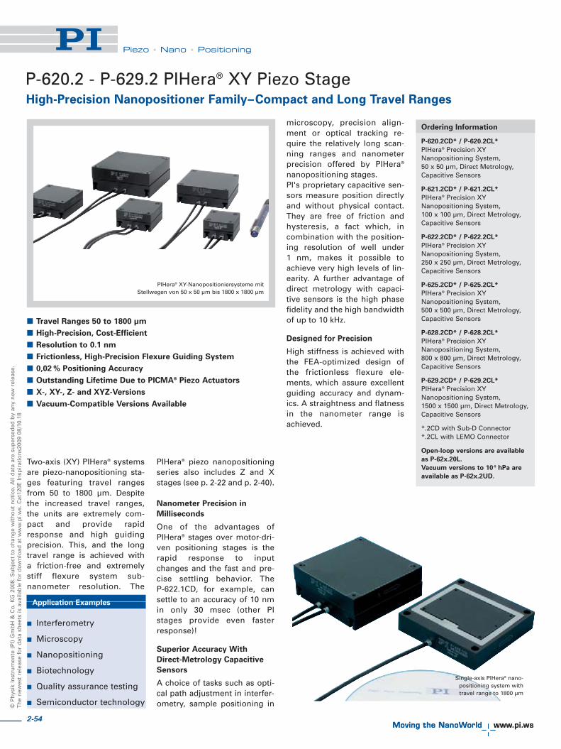
© P
hys
ik In
stru
men
te (
PI)
Gm
bH
& C
o. K
G 2
008.
Su
bje
ct t
o c
han
ge
wit
ho
ut
no
tice
. All
dat
a ar
e su
per
sed
ed b
y an
y n
ew r
elea
se.
Th
e n
ewes
t re
leas
e fo
r d
ata
shee
ts is
ava
ilab
le f
or
do
wn
load
at
ww
w.p
i.ws.
Cat
120E
Insp
irat
ion
s200
9 08
/10.
18
Piezo • Nano • Positioning
Two-axis (XY) PIHera® systemsare piezo-nanopositioning sta -ges featuring travel rangesfrom 50 to 1800 μm. Despitethe increased travel ranges, the units are extremely com-pact and provide rapidresponse and high guiding precision. This, and the longtravel range is achieved with a friction-free and extremelystiff flexure system sub-nanometer resolution. The
PIHera® piezo nanopositioningseries also includes Z and Xstages (see p. 2-22 and p. 2-40).
Nanometer Precision in
Milliseconds
One of the advantages ofPIHera® stages over motor-dri-ven positioning stages is therapid response to inputchanges and the fast and pre-cise settling behavior. The P-622.1CD, for example, cansettle to an accuracy of 10 nmin only 30 msec (other PIstages provide even fasterresponse)!
Superior Accuracy With
Direct-Metrology Capacitive
Sensors
A choice of tasks such as opti-cal path adjustment in interfer-ometry, sample positioning in
microscopy, precision align-ment or optical tracking re -quire the relatively long scan-ning ranges and nanometerprecision offered by PIHera®
nanopositioning stages.PI's proprietary capacitive sen-sors measure position directlyand without physical contact.They are free of friction andhysteresis, a fact which, incombination with the position-ing resolution of well under 1 nm, makes it possible toachieve very high levels of lin-earity. A further advantage ofdirect metrology with capaci-tive sensors is the high phasefidelity and the high bandwidthof up to 10 kHz.
Designed for Precision
High stiffness is achieved withthe FEA-optimized design ofthe frictionless flexure ele-ments, which assure excellentguiding accuracy and dynam-ics. A straightness and flatnessin the nanometer range isachieved.
Application Examples
� Interferometry
� Microscopy
� Nanopositioning
� Biotechnology
� Quality assurance testing
� Semiconductor technology
Ordering Information
P-620.2CD* / P-620.2CL*
PIHera® Precision XYNanopositioning System, 50 x 50 μm, Direct Metrology,Capacitive Sensors
P-621.2CD* / P-621.2CL*
PIHera® Precision XYNanopositioning System, 100 x 100 μm, Direct Metrology,Capacitive Sensors
P-622.2CD* / P-622.2CL*
PIHera® Precision XYNanopositioning System, 250 x 250 μm, Direct Metrology,Capacitive Sensors
P-625.2CD* / P-625.2CL*
PIHera® Precision XYNanopositioning System, 500 x 500 μm, Direct Metrology,Capacitive Sensors
P-628.2CD* / P-628.2CL*
PIHera® Precision XYNanopositioning System, 800 x 800 μm, Direct Metrology,Capacitive Sensors
P-629.2CD* / P-629.2CL*
PIHera® Precision XYNanopositioning System, 1500 x 1500 μm, Direct Metrology,Capacitive Sensors
*.2CD with Sub-D Connector*.2CL with LEMO Connector
Open-loop versions are available
as P-62x.20L.
Vacuum versions to 10-9 hPa are
available as P-62x.2UD.
High-Precision Nanopositioner Family–Compact and Long Travel Ranges
P-620.2 - P-629.2 PIHera® XY Piezo Stage
PIHera® XY-Nanopositioniersysteme mitStellwegen von 50 x 50 μm bis 1800 x 1800 μm
� Travel Ranges 50 to 1800 μm
� High-Precision, Cost-Efficient
� Resolution to 0.1 nm
� Frictionless, High-Precision Flexure Guiding System
� 0,02 % Positioning Accuracy
� Outstanding Lifetime Due to PICMA® Piezo Actuators
� X-, XY-, Z- and XYZ-Versions
� Vacuum-Compatible Versions Available
Single-axis PIHera® nano-positioning system with travel range to 1800 μm
2-54

2-55
Piezo • Nano • Positioning
Piezo Flexure Stages /High-Speed Scanning Systems
Nanopositioning / Piezoelectrics
Linear Actuators & Motors
Fast Steering Mirrors / Active Optics
Piezo Drivers / Servo Controllers
Piezoelectrics in Positioning
Nanometrology
Micropositioning
Linear
Vertical & Tip/Tilt
2- and 3-Axis
6-Axis
Single-Channel
Multi-Channel
Modular
Accessories
Index
Technical Data
Model P-620.2CD/ P-621.2CD/ P-622.2CD/ P-625.2CD/ P-628.2CD/ P-629.2CD P-62x.20L Units Tolerance
P-620.2CL P-621.2CL P-622.2CL P-625.2CL P-628.2CL P-629.2CL open-loop versions
Active axes X, Y X, Y X, Y X, Y X, Y X, Y X, Y
Motion and positioning
Integrated sensor Capacitive Capacitive Capacitive Capacitive Capacitive Capacitive –
Open-loop travel X, Y, -20 to +120 V 60 120 300 600 950 1800 as P-62x.2CD μm min. (+20 %/-0 %)
Closed-loop travel 50 100 250 500 800 1500 – μm
Open-loop resolution 0.1 0.2 0.4 0.5 0.5 2 as P-62x.2CD nm typ.
Closed-loop resolution 0.2 0.4 0.7 1.4 3.5 3.5 – nm typ.
Linearity 0.02 0.02 0.02 0.03 0.03 0.03 – % typ.
Repeatability ±2 ±2 ±2 ±5 ±10 ±14 as P-62x.2CD nm typ.
Pitch / yaw ±3 ±3 ±3 ±3 ±20 ±30 as P-62x.2CD μrad typ.
Mechanical properties
Stiffness 0.22 0.25 0.2 0.1 0.05 0.1 as P-62x.2CD N/μm ±20 %
Unloaded resonant frequency in X, 575 420 225 135 75 60 as P-62x.2CD Hz ±20 %
Unloaded resonant frequency in Y 800 535 300 195 105 100 as P-62x.2CD Hz ±20 %
Resonant frequency in X @ 50 g 270 285 180 120 60 55 as P-62x.2CD Hz ±20 %
Resonant frequency in Y @ 50 g 395 365 215 150 85 85 as P-62x.2CD Hz ±20 %
Resonant frequency in X @ 100 g 285 220 160 105 55 50 as P-62x.2CD Hz ±20 %
Resonant frequency in Y @ 100 g 300 285 175 125 75 80 as P-62x.2CD Hz ±20 %
Push/pull force capacity in motion direction 10 / 5 10 / 8 10 / 8 10 / 8 10 / 8 10 / 8 as P-62x.2CD N Max.
Load capacity 10 10 10 10 10 10 as P-62x.2CD N Max.
Lateral Force 10 10 10 10 10 10 as P-62x.2CD N Max.
Drive properties
Ceramic type PICMA® P-883 PICMA® P-885 PICMA® P-885 PICMA® P-885 PICMA® P-887 PICMA® P-888 as P-62x.2CD
Electrical Capacitance 0.35 1.5 3.1 6.2 19 52 as P-62x.2CD μF ±20 %
Dynamic operating current coefficient 0.9 1.9 1.9 1.6 3 4.3 as P-62x.2CD μA/(Hz•μm) ±20 %
Miscellaneous
Operating temperature range -20 to 80 -20 to 80 -20 to 80 -20 to 80 -20 to 80 -20 to 80 -20 to 150 °C
Material Aluminum Aluminum Aluminum Aluminum Aluminum Aluminum Aluminum
Mass 0.195 0.295 0.348 0.43 0.7 1.37 as P-62x.2CD kg ±5 %
Cable length 1.5 1.5 1.5 1.5 1.5 1.5 1.5 m ±10 mm
Sensor / voltage connection CD version: CD version: CD version: CD version: CD version: CD version: 2x LEMO2x Sub-D special 2x Sub-D special 2x Sub-D special 2x Sub-D special 2x Sub-D special 2x Sub-D special (no sensor)CL version: CL version: CL version: CL version: CL version: CL version:LEMO LEMO LEMO LEMO LEMO LEMO
Lower axis: X; upper axis: Y. Resolution of PI Piezo Nanopositioners is not limited by friction or stiction. The value given is noise equivalent motion with E-710 controller (p. 2-128)Recommended controllerCD version: E-610 servo controller / amplifier (p. 2-110), E-625 servo controller, bench-top (p. 2-114), E-665 powerful servo controller, bench-top (p. 2-116)
Multi-channel digital controllers: E-710 bench-top (p. 2-128), E-712 modular (p. 2-140), E-725 high-power (p. 2-126), E-761 PCI board (p. 2-140)CL version: E-500 modular piezo controller system (p. 2-142) with E-505 amplifier module (1 per axis, high power) (p. 2-147) and E-509 controller (p. 2-152)Open-loop versions: E-500 modular piezo controller system (p. 2-142) with E-505 amplifier module (1 per axis, high power) (p. 2-147)
P-62x.2CD/.2CL/.20L Abmessungen in mm

2-56
© P
hys
ik In
stru
men
te (
PI)
Gm
bH
& C
o. K
G 2
008.
Su
bje
ct t
o c
han
ge
wit
ho
ut
no
tice
. All
dat
a ar
e su
per
sed
ed b
y an
y n
ew r
elea
se.
Th
e n
ewes
t re
leas
e fo
r d
ata
shee
ts is
ava
ilab
le f
or
do
wn
load
at
ww
w.p
i.ws.
Cat
120E
Insp
irat
ion
s200
9 08
/10.
18
Piezo • Nano • Positioning
P-713 · P-714 XY Piezo ScannerCost-Effective OEM System with Low Profile
P-713 / P-714 family piezo scan-ners and positioners with travelranges of 15 x 15 μm featureespecially compact designs.Ideal applications for the P-713and P-714 are high-dynamicsscanning or tracking tasks suchas sub-stepping methods forenhancing image resolution.Such tasks involve moving tospecific positions in a small area(e. g. marked cells or CCD pho-tosites) and from there follow-
ing or performing motion withan amplitude of a few microns.The resonant frequency of up toover 2 kHz makes for settlingtimes of a few milliseconds,even after a full-range move, allwith closed-loop repeatability ofunder 5 nm.A single-axis version with simi-lar footprint is available as P-712 (see p. 2-14) and XY ver-sions with longer travel rangesare available on request.
Flexibility
P-713 and P-714 nanoposition-ers are offered in different ver-sions for different applications.The lowest-cost, basic versionof the P-713 offers guiding accu-racy in the motion plane of 50 μrad, a value generally goodenough for dithering and inter-lacing tasks in scanning pat-terns of a few microns. Formore demanding applications,the P-714 offers greater accura-cy, typically 5 μrad or <10 nmabsolute.
Nanometer Position Servo-
Control
If servo-control is required andno external position sensor isavailable, the P-714.2SL version,equipped with high-resolutionstrain gauge sensors (SGS) canprovide nanometer-range reso-lution.High-resolution, broadband,strain gauge sensors (SGS) areapplied to appropriate locationson the drive train and measurethe displacement of the movingpart of the stage relative to thebase indirectly. The SGS sen-sors assure optimum positionstability in the nanometer rangeand fast response.
Ceramic Insulated Piezo
Actuators Provide Long
Lifetime
Highest possible reliability isassured by the use of award-winning PICMA® multilayerpiezo actuators. PICMA® actua-
tors are the only actuators onthe market with ceramic-onlyinsulation, which makes themresistant to ambient humidityand leakage-current failures.They are thus far superior toconventional actuators in relia-bility and lifetime.
Application Examples
� Pixel dithering / sub-step-ping image resolutionenhancement
� Quality assurance testing
� Optical Metrology
� Microscopy
� Imaging
� CCD / CMOS camera technology
Ordering Information
P-713.20L
Low-Profile OEM XY Nanoscanner,15 x 15 μm, No Sensor, LEMOConnector
P-714.20L
Low-Profile OEM XY Nanoscanner,15 x 15 μm, Improved GuidingAccuracy, No Sensor, LEMOConnector
P-713.2SL
Low-Profile OEM XY Nanoscanner,15 x 15 μm, SGS-Sensor, LEMOConnector
P-714.2SL
Low-Profile OEM XY Nanoscanner,15 x 15 μm, Improved GuidingAccuracy, SGS-Sensor, LEMOConnector
P-713/P-714 dimensions in mm
P-714 Piezo Scanner
� Ideal for Pixel Sub-Stepping in Image Enhancement
� Small Footprint and Low Profile: 45 x 45 x 6 mm with
Clear Aperture
� Very Cost-Effective Design
� Travel Ranges to 20 x 20 μm
� Parallel Kinematics for Better Multi-Axis Accuracy and
Dynamics
The resonant frequency ofan unloaded P-713 / P-714
scanner is over 2 kHz

2-57
Piezo • Nano • Positioning
Piezo Flexure Stages /High-Speed Scanning Systems
Nanopositioning / Piezoelectrics
Linear Actuators & Motors
Fast Steering Mirrors / Active Optics
Piezo Drivers / Servo Controllers
Piezoelectrics in Positioning
Nanometrology
Micropositioning
Linear
Vertical & Tip/Tilt
2- and 3-Axis
6-Axis
Single-Channel
Multi-Channel
Modular
Accessories
Index
Settling time for the P-713/P-714 at 15 μm is in the 2 ms range
Technical Data
Model P-713.20L P-713.2SL P-714.20L P-714.2SL Units Tolerance
Active axes X, Y X, Y X, Y X, Y
Motion and positioning
Integrated sensor - SGS - SGS
Open-loop travel, -20 to +120 V 20 20 20 20 μm min. (+20 %/0 %)
Closed-loop travel - 15 - 15 μm
Open-loop resolution 0.1 0.1 0.1 0.1 nm typ.
Closed-loop resolution - 1 - 1 nm typ.
Linearity - 0.3 - 0.3 % typ.
Repeatability - <4 - <4 nm typ.
Pitch typ. ±1 typ. ±1 typ. ±1 typ. ±1 μrad typ.
max. ±5 max. ±5 max. ±5 max. ±5
Yaw typ. ±40 typ. ±40 typ. ±40 typ. ±40 μrad μradmax. ±50 max. ±50 max. ±50 max. ±50
Mechanical properties
Stiffness 0.8 0.8 0.8 0.8 N/μm ±20 %
Unloaded resonant frequency 2250 2250 2250 2250 Hz ±20 %
Resonant frequency under load 1310 (20 g) 1310 (20 g) 1310 (20 g) 1310 (20 g) Hz ±20 %1020 (50 g) 1020 (50 g) 1020 (50 g) 1020 (50 g)460 (100 g) 460 (100 g) 460 (100 g) 460 (100 g)
Push/pull force capacity 5 / 5 5 / 5 5 / 5 5 / 5 N Max.in motion direction
Load capacity 2 2 2 2 N Max.
Drive properties
Ceramic type PICMA® P-882 PICMA® P-882 PICMA® P-882 PICMA® P-882
Electrical capacitance in X , Y 0.31 0.31 0.31 0.31 μF ±20 %
Dynamic operating current 2.5 2.5 2.5 2.5 μA/(Hz • μm) ±20 %coefficient (DOCC) in X, Y
Miscellaneous
Operating temperature range -20 to 80 -20 to 80 -20 to 80 -20 to 80 °C
Material Stainless steel, Stainless steel, Stainless steel, Stainless steel, ferromagnetic ferromagnetic ferromagnetic ferromagnetic
Dimensions 45 x 45 x 6 45 x 45 x 6 45 x 45 x 6 45 x 45 x 6
Mass 0.1 0.1 0.1 0.1 kg ±5 %
Cable length 1.5 1.5 1.5 1.5 m ±10 mm
Sensor connection - LEMO - LEMO
Voltage connection LEMO LEMO LEMO LEMO
Resolution of PI piezo nanopositioners is not limited by friction or stiction. Value given is noise equivalent motion with E-503 amplifier (p. 2-146)
Dynamic Operating Current Coefficient in μA per Hz and μm. Example: Sinusoidal scan of 10 μm at 100 Hz requires approximately 2.5 mA drive current.
Recommended controller / amplifier
Single-channel (1 per axis): E-610 servo controller / amplifier (p. 2-110), E-625 servo controller, bench-top (p. 2-114), E-621 controller module (p. 2-160)
Multi-channel: modular piezo controller system E-500 (p. 2-142) with amplifier module E-503 (three channels) (p. 2-146) or E-505 (1 per axis, high-power) (p. 2-147)and E-509 controller (p. 2-152)
System properties
System controller P-714.2SL with modular system E-500 (E-503 amplifier and E-509 sensor module); 20 g load
Bandwidth, small signal 300 Hz
Bandwidth, large signal 220 Hz
Settling time (10 % step width) 3.1 ms
Settling time (full travel) 4.5 ms
See the “Selection Guide” forcomparison with other nanopo-sitioning systems (see p. 2-4 ff ).

2-58
© P
hys
ik In
stru
men
te (
PI)
Gm
bH
& C
o. K
G 2
008.
Su
bje
ct t
o c
han
ge
wit
ho
ut
no
tice
. All
dat
a ar
e su
per
sed
ed b
y an
y n
ew r
elea
se.
Th
e n
ewes
t re
leas
e fo
r d
ata
shee
ts is
ava
ilab
le f
or
do
wn
load
at
ww
w.p
i.ws.
Cat
120E
Insp
irat
ion
s200
9 08
/10.
18
Piezo • Nano • Positioning
P-612 XY Piezo Nanopositioning SystemCompact, Clear Aperture
The P-612.2SL is a piezo-basednanopositioning system featur-ing a compact footprint of only60 x 60 mm and a height of 18 mm. Due to the 20 x 20 mmopen aperture, the system isexcellently suited for samplepositioning in microscopy orscanning applications. Equip p edwith piezo drives and zero-stic-tion, zero-friction flexure guid-ing system, the series providesnanometer-range resolution andmillisecond response time. A Zstage with the same form factoris available for vertical position-ing applications (see P-612.ZSLp. 2-36).
Cost-Effective Design
Flexures optimized with FiniteElement Analysis (FEA) are usedto guide the compact, low-coststage. Flexures allow extremelyhigh-precision motion, no mat-ter how minute, as they arecompletely free of play and fric-
tion. They also optimize stiff-ness in and perpendicular to thedirection of motion.
Position Servo-Control with
Nanometer Resolution
High-resolution, broadband,strain gauge sensors (SGS) areapplied to appropriate locationson the drive train and measurethe displacement of the movingpart of the stage relative to thebase directly. The SGS sensorsassure optimum position stabili-ty in the nanometer range andfast response.
The open-loop models are idealfor applications where fastresponse and very high resolu-tion are essential, but absolutepositioning is not important.They can also be used in appli-cations where the position iscontrolled by an external linearposition sensor such as an inter-ferometer, a PSD (position sen-
sitive diode), CCD chip / imageprocessing system, or the eyesand hands of an operator.
Ceramic Insulated Piezo
Actuators Provide Long
Lifetime
Highest possible reliability isassured by the use of award-winning PICMA® multilayerpiezo actuators. PICMA® actua-tors are the only actuators onthe market with ceramic-onlyinsulation, which makes themresistant to ambient humidityand leakage-current failures.They are thus far superior toconventional actuators in relia-bility and lifetime.
Ordering Information
P-612.2SL
XY Nanopositioning System with 20 x 20 mm Aperture, 100 x 100 μm,Strain Gauge Sensors
P-612.20L
XY Nanopositioning System withAperture 20 x 20 mm, 100 x 100 μm,Open-Loop
P-612.2SL XY piezo stage (CD for size comparison)
� Compact: Footprint 60 x 60 mm
� 100 x 100 μm Closed-Loop Travel Range
(130 x 130 Open-Loop)
� For Cost-Sensitive Applications
� Clear Aperture 20 x 20 mm
� Parallel-Kinematics for Enhanced
Responsiveness / Multi-Axis Precision
� Outstanding Lifetime Due to PICMA® Piezo Actuators
� Z-Stage Also Available
System properties
System configuration P-612.2 SL and E-500 modular systemwith E-503 amplifier and E-509 sensormodule, 100 load
Amplifier bandwidth, small signal 45 Hz
Settling time (10 % step width) 15 ms
P-612.2 dimensions in mm

2-59
Piezo • Nano • Positioning
Piezo Flexure Stages /High-Speed Scanning Systems
Nanopositioning / Piezoelectrics
Linear Actuators & Motors
Fast Steering Mirrors / Active Optics
Piezo Drivers / Servo Controllers
Piezoelectrics in Positioning
Nanometrology
Micropositioning
Linear
Vertical & Tip/Tilt
2- and 3-Axis
6-Axis
Single-Channel
Multi-Channel
Modular
Accessories
Index
Technical Data
Model P-612.2SL P-612.20L Units Tolerance
Active axes X, Y X, Y
Motion and positioning
Integrated sensor SGS –
Open-loop travel, -20 to +120 V 130 130 μm min. (+20 %/-0 %)
Closed-loop travel 100 – μm
Open-loop resolution 0.8 0.8 nm typ.
Closed-loop resolution 5 – nm typ.
Linearity 0.4 – % typ.
Repeatability <10 – nm typ.
Pitch ±10 ±10 μrad typ.
Yaw in X/ Y ±10 / ±50 ±10 / ±50 μrad typ.
Mechanical properties
Stiffness 0.15 0.15 N/μm ±20 %
Unloaded resonant frequency 400 400 Hz ±20 %
Resonant frequency @ 100 g 200 200 Hz ±20 %
Push/pull force capacity in motion direction 15 / 5 15 / 5 N Max.
Load capacity 15 15 N Max.
Drive properties
Ceramic type PICMA® P-885 PICMA® P-885
Electrical capacitance 1.5 1.5 μF ±20 %
Dynamic operating current coefficient 1.9 1.9 μA/(Hz • μm) ±20 %
Miscellaneous
Operating temperature range -20 to 80 -20 to 80 °C
Material Aluminum, steel Aluminum, steel
Mass 105 105 g ±5 %
Cable length 1.5 1.5 m ±10 mm
Sensor connector LEMO connector –
Voltage connection LEMO connector LEMO connector
Resolution of PI Piezo Nanopositioners is not limited by friction or stiction. Noise equivalent motion with E-503 amplifier (p. 2-146)Recommended controllerSingle-channel (1 per axis): E-610 servo-controller / amplifier (p. 2-110) , E-625 servo-controller, bench-top (p. 2-114), E-621 controller module (p. 2-160)Multi-channel: modular piezo controller system E-500 (p. 2-142) with amplifier module E-503 (three channels) (p. 2-146) or E-505 (1 per axis, high-power) (p. 2-147) and E-509 controller (p. 2-152)
P-612 are available as XY-scanners (P-612.2SL, on the left) andvertical stages (P-612.ZSL, on the right) providing a travel
range of 100 μm per axis
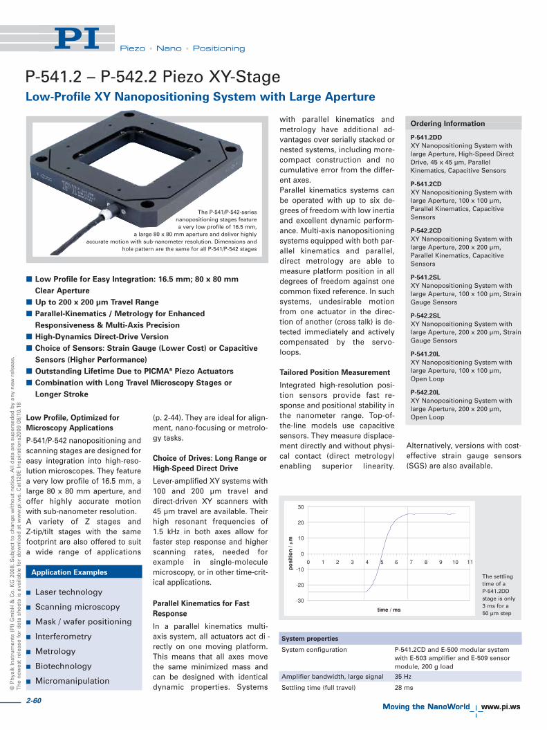
2-60
© P
hys
ik In
stru
men
te (
PI)
Gm
bH
& C
o. K
G 2
008.
Su
bje
ct t
o c
han
ge
wit
ho
ut
no
tice
. All
dat
a ar
e su
per
sed
ed b
y an
y n
ew r
elea
se.
Th
e n
ewes
t re
leas
e fo
r d
ata
shee
ts is
ava
ilab
le f
or
do
wn
load
at
ww
w.p
i.ws.
Cat
120E
Insp
irat
ion
s200
9 08
/10.
18
Piezo • Nano • Positioning
P-541.2 – P-542.2 Piezo XY-StageLow-Profile XY Nanopositioning System with Large Aperture
Low Profile, Optimized for
Microscopy Applications
P-541/P-542 nanopositioning andscanning stages are de signed foreasy integration into high-reso-lution microscopes. They featurea very low profile of 16.5 mm, alarge 80 x 80 mm aperture, andoffer highly accurate motionwith sub-nanometer resolution.A variety of Z stages and Z-tip/tilt stages with the samefootprint are also offered to suita wide range of applications
(p. 2-44). They are ideal for align-ment, nano-focusing or metrolo-gy tasks.
Choice of Drives: Long Range or
High-Speed Direct Drive
Lever-amplified XY systems with100 and 200 μm travel anddirect-driven XY scanners with45 μm travel are available. Theirhigh resonant frequencies of 1.5 kHz in both axes allow forfaster step response and higherscanning rates, needed forexample in single-moleculemicroscopy, or in other time-crit-ical applications.
Parallel Kinematics for Fast
Response
In a parallel kinematics multi-axis system, all actuators act di -rectly on one moving platform.This means that all axes movethe same minimized mass andcan be designed with identicaldynamic properties. Systems
with parallel kinematics andmetrology have additional ad -vantages over serially stacked ornested systems, including more-compact construction and nocumulative error from the differ-ent axes. Parallel kinematics systems canbe operated with up to six de -grees of freedom with low inertiaand excellent dynamic perform-ance. Multi-axis nanopositioningsystems equipped with both par-allel kinematics and parallel,direct metrology are able tomeasure platform position in alldegrees of freedom against onecommon fixed reference. In suchsystems, undesirable motionfrom one actuator in the direc-tion of another (cross talk) is de -tected immediately and activelycompensated by the servo-loops.
Tailored Position Measurement
Integrated high-resolution posi-tion sensors provide fast re -sponse and positional stability inthe nanometer range. Top-of-the-line models use capacitivesensors. They measure displace-ment directly and without physi-cal contact (direct metro logy)enabling superior linearity.
Alternatively, versions with cost-effective strain gauge sensors(SGS) are also available.
Application Examples
� Laser technology
� Scanning microscopy
� Mask / wafer positioning
� Interferometry
� Metrology
� Biotechnology
� Micromanipulation
Ordering Information
P-541.2DD
XY Nanopositioning System withlarge Aperture, High-Speed DirectDrive, 45 x 45 μm, ParallelKinematics, Capacitive Sensors
P-541.2CD
XY Nanopositioning System withlarge Aperture, 100 x 100 μm,Parallel Kinematics, CapacitiveSensors
P-542.2CD
XY Nanopositioning System withlarge Aperture, 200 x 200 μm,Parallel Kinematics, CapacitiveSensors
P-541.2SL
XY Nanopositioning System withlarge Aperture, 100 x 100 μm, StrainGauge Sensors
P-542.2SL
XY Nanopositioning System withlarge Aperture, 200 x 200 μm, StrainGauge Sensors
P-541.20L
XY Nanopositioning System withlarge Aperture, 100 x 100 μm, Open Loop
P-542.20L
XY Nanopositioning System withlarge Aperture, 200 x 200 μm, Open Loop
� Low Profile for Easy Integration: 16.5 mm; 80 x 80 mm
Clear Aperture
� Up to 200 x 200 μm Travel Range
� Parallel-Kinematics / Metrology for Enhanced
Responsiveness & Multi-Axis Precision
� High-Dynamics Direct-Drive Version
� Choice of Sensors: Strain Gauge (Lower Cost) or Capacitive
Sensors (Higher Performance)
� Outstanding Lifetime Due to PICMA® Piezo Actuators
� Combination with Long Travel Microscopy Stages or
Longer Stroke
The P-541/P-542-series nanopositioning stages feature a very low profile of 16.5 mm,
a large 80 x 80 mm aperture and deliver highly accurate motion with sub-nanometer resolution. Dimensions and
hole pattern are the same for all P-541/P-542 stages
The settlingtime of a P-541.2DDstage is only3 ms for a 50 μm step
-30
-20
-10
0
10
20
30
0 1 2 3 4 5 6 7 8 9 10 11
time / ms
po
siti
on
/m
System properties
System configuration P-541.2CD and E-500 modular systemwith E-503 amplifier and E-509 sensormodule, 200 g load
Amplifier bandwidth, large signal 35 Hz
Settling time (full travel) 28 ms

2-61
Piezo • Nano • Positioning
Piezo Flexure Stages /High-Speed Scanning Systems
Nanopositioning / Piezoelectrics
Linear Actuators & Motors
Fast Steering Mirrors / Active Optics
Piezo Drivers / Servo Controllers
Piezoelectrics in Positioning
Nanometrology
Micropositioning
Linear
Vertical & Tip/Tilt
2- and 3-Axis
6-Axis
Single-Channel
Multi-Channel
Modular
Accessories
Index
Technical Data
Model P-541.2CD P-542.2CD P-541.2DD P-541.2SL P-542.2SL P-541.20L P-542.20L Units Tolerance
Active axes X, Y X, Y X, Y X, Y X, Y X, Y X, Y
Motion and positioning
Integrated sensor Capacitive Capacitive Capacitive SGS SGS – –
Open-loop travel, -20 to +120 V 175 x 175 290 x 290 60 x 60 175 x 175 290 x 290 175 x 175 290 x 290 μm min. (+20 %/0 %)
Closed-loop travel 100 x 100 200 x 200 45 x 45 100 x 100 200 x 200 – – μm
Closed-loop / open-loop resolution 0.2 / 0.3 0.4 / 0.7 0.1 / 0.3 0.2 / 2.5 0.4 / 4 0.2 / – 0.4 / – nm typ.
Linearity 0.03 0.03 0.03* 0.2 0.2 – – % typ.
Repeatability <5 <5 <5 <10 <10 – – nm typ.
Pitch <±5 <±5 <±3 <±5 <±5 <±5 <±5 μrad typ.
Yaw <±10 <±10 <±3 <±10 <±10 <±10 <±10 μrad typ.
Mechanical properties
Stiffness in motion direction 0.47 0.4 10 0.47 0.4 0.47 0.4 N/μm ±20 %
Unloaded resonant frequency 255 230 1550 255 230 255 230 Hz ±20 %
Resonant frequency @ 100 g 200 190 – 200 190 200 190 Hz ±20 %
Resonant frequency @ 200 g 180 – 1230 180 – 180 – Hz ±20 %
Resonant frequency @ 300 g 150 145 – 150 145 150 145 Hz ±20 %
Push/pull force capacity 100 / 30 100 / 30 100 / 30 100 / 30 100 / 30 100 / 30 100 / 30 N Max.in motion direction
Load capacity 20 20 20 20 20 20 20 N Max.
Drive properties
Ceramic type PICMA® PICMA® PICMA® PICMA® PICMA® PICMA® PICMA®
P-885 P-885 P-885 P-885 P-885 P-885 P-885
Electrical capacitance per axis 4.2 7.5 9 4.2 7.5 4.2 7.5 μF ±20 %
Dynamic operating current 5.2 4.8 25 5.2 4.8 5.2 4.8 μA/(Hz • μm) ±20 %coefficient per axis
Miscellaneous
Operating temperature range 20 to 80 20 to 80 20 to 80 -20 to 80 -20 to 80 -20 to 80 -20 to 80 °C
Material Aluminum Aluminum Aluminum Aluminum Aluminum Aluminum Aluminum
Mass 1100 1150 1210 1050 1100 1050 1100 kg ±5 %
Cable length 1.5 1.5 1.5 1.5 1.5 1.5 1.5 m ±10 mm
Sensor connection Sub-D Special Sub-D Special Sub-D Special LEMO LEMO – –
Voltage connection Sub-D Special Sub-D Special Sub-D Special LEMO LEMO LEMO LEMO
Resolution of PI Piezo Nanopositioners is not limited by friction or stiction. Value given is noise equivalent motion with E-503 (p. 2-146) or E-710 controller (p. 2-128).Dynamic Operating Current Coefficient in μA per Hz and μm. Example: Sinusoidal scan of 10 μm at 10 Hz requires approximately 0.48 mA drive current for the P-542.2CD.*With digital controller. Non-linearity of direct drive stages measured with analog controllers is up to 0.1 % typ.Recommended controller / amplifier Single-channel (1 per axis): E-610 servo controller / amplifier (p. 2-110), E-625 servo controller, bench-top (p. 2-114), E-621 controller module (p. 2-160)Multi-channel: modular piezo controller system E-500 (p. 2-142) with amplifier module E-503 (three channels) (p. 2-146) or E-505 (1 per axis, high-power) (p. 2-147) and E-509 controller (p. 2-152) (for systemswith sensors)Multi-channel digital controllers: E-710 bench-top (p. 2-128), E-712 modular (p. 2-140), E-725 high-power (p. 2-126), E-761 PCI board (p. 2-130)
P-541.2 and P-542.2, dimensions in mm

2-62
© P
hys
ik In
stru
men
te (
PI)
Gm
bH
& C
o. K
G 2
008.
Su
bje
ct t
o c
han
ge
wit
ho
ut
no
tice
. All
dat
a ar
e su
per
sed
ed b
y an
y n
ew r
elea
se.
Th
e n
ewes
t re
leas
e fo
r d
ata
shee
ts is
ava
ilab
le f
or
do
wn
load
at
ww
w.p
i.ws.
Cat
120E
Insp
irat
ion
s200
9 08
/10.
18
Piezo • Nano • Positioning
P-733.2 · P-733.3 XY(Z) Piezo-Nanopositioning Stage
P-733 XY and XYZ piezo drivenstages are fast and highly accu-rate nanopositioning and scan-ning systems. They provide apositioning and scanningrange of 100 x 100 (x10) μmtogether with sub-nanometerresolution and are equippedwith parallel-metrology capaci-
tive position feedback for supe-rior multi-axis linearity andrepeatability. The guiding accu-racy minimizes runout to under10 nm over the whole travelrange. In addition, the high-speed Z-axis of the P-733.3CDcan actively compensate anyout-of-plane Z-axis deviationduring XY motion.
Fastest Multi-Axis Systems /
Direct Drive, Low Profile and
Large Apertures
P-733.2DD / .3DD multi-axispiezo nanopositioning systemsare the fastest ultra-high-precision, open-frame stagesfor scanning microscopy. Theyprovide a positioning and scan-ning range of 30 x 30 (x10) μm.P-733 nanopositioning andscanning stages feature verylow profiles, as low as 20 mm(0.8 inch). The novel, high-stiff-ness direct drive gives the sys-tems resonant frequencies ashigh as 2.2 kHz (4 x that of
other comparable systems),enabling millisecond scanningrates with sub-nanometer reso-lution.
Parallel-Kinematics /
Metrology for Enhanced
Responsiveness
In a parallel kinematics multi-axis system, all actuators actdirectly on one moving plat-form. This means that all axesmove the same minimizedmass and can be designed withidentical dynamic properties.Multi-axis nano positioningsystems equipped with bothparallel kinematics and paral-lel, direct metrology are able tomeasure platform position inall degrees of freedom againstone common fixed reference.In such systems, undesirablemotion from one actuator inthe direction of another (crosstalk) is detected immediatelyand actively compensated bythe servo-loops.
Capacitive Sensors for
Subnanometer Resolution
PI's proprietary capacitive sen-sors measure position directlyand without physical contact.They are free of friction andhysteresis, a fact which, incombination with the position-ing resolution of well under 1nm, makes it possible toachieve very high levels of lin-earity. A further advantage ofdirect metrology with capaci-tive sensors is the high phasefidelity and the high bandwidthof up to 10 kHz. The closed-loop resolution is 0.3 nm forthe X and Y axes and 0.2 nmfor the optional Z-axis. Thedirect drive versions are ratedto 0.1 nm resolution for everyaxis.
Large Variety of Models for a
Broad Range of Applications
For Z-axis scanning appli ca-tions, the P-733.ZCD (see
p. 2-42) version is availablewith a travel range of 100 μm. For ultra-high-vacuum appli ca-tions down to 10-9 hPa, nanopo-sitioning systems as well ascomprehensive accessories,such as suitable feedthroughs,are available.
� Travel Ranges to 100 x 100 μm in X,Y & to 10 μm in Z
� Resolution to 0.1 nm with Capacitive Sensors
� High-Speed Versions with Direct Drive
� Vacuum and Non-Magnetic Versions
� Parallel Kinematics for Better Multi-Axis Accuracy and
Dynamics
� Parallel Metrology for Active Trajectory Control
� Frictionless, High-Precision Flexure Guiding System
� Clear Aperture 50 x 50 mm for Transmitted-Light Applications
Ordering Information
P-733.2DD
High-Dynamics High-Precision XY Nanopositioning System, 30 x 30 μm, Direct Drive, CapacitiveSensors, Parallel Metrology, Sub-D Connector
P-733.3DD
High-Dynamics Precision XYZ Nanopositioning System, 30 x 30 x 10 μm, Direct Drive,Capacitive Sensors, ParallelMetrology, Sub-D Connector
P-733.2CD* / P-733.2CL*
High-Precision XY NanopositioningSystem, 100 x 100 μm, CapacitiveSensors, Parallel Metrology
P-733.3CD* / P-733.3CL*
Precision XYZ NanopositioningSystem, 100 x 100 x 10 μm,Capacitive Sensors, ParallelMetrology
P-733.2VL* / P-733.2VD*
High-Precision XY NanopositioningSystem, 100 x 100 μm, CapacitiveSensors, Parallel Metrology,Vacuum Compatible to 10-6 hPa
P-733.2UD
High-Precision XY NanopositioningSystem, 100 x 100 μm, CapacitiveSensors, parallel metrology, Sub-D Connector, VacuumCompatible to 10-9 hPa
*.xxD with Sub-D Connector
*.xxL with LEMO Connector
Ask about custom designs
Application Examples
� Image processing /stablilization
� Scanning microscopy
� Surface inspection
� Metrology / interferometry
� Biotechnology
� Semiconductor testing
� Mask / wafer positioning
� Micromanipulation
� Nanopositioning with highflatness & straightness
High-Precision XY(Z) Scanner Family with Aperture
P -733.3 DD (left) and P -733.2 DD, high-speed, direct drive XY(Z) scanning stages are the fastest scanning stages with large aperture currently
available (2.2 kHz resonant frequency!). Both units feature a footprint of only 100 x 100 mm. CD for size comparison.
P-733.2UD non-magnetic XY scan-ning stage for UHV to 10-9 hPa

2-63
Piezo • Nano • Positioning
Piezo Flexure Stages /High-Speed Scanning Systems
Nanopositioning / Piezoelectrics
Linear Actuators & Motors
Fast Steering Mirrors / Active Optics
Piezo Drivers / Servo Controllers
Piezoelectrics in Positioning
Nanometrology
Micropositioning
Linear
Vertical & Tip/Tilt
2- and 3-Axis
6-Axis
Single-Channel
Multi-Channel
Modular
Accessories
Index
P-733.3 dimensions in mmP-733.2 dimensions in mm
Technical Data
Model P-733.2CD P-733.3CD P-733.2DD P-733.3DD Units ToleranceP-733.2CL P-733.3CL
Active axes X, Y X, Y, Z X, Y X, Y, Z
Motion and positioning
Integrated sensor Capacitive Capacitive Capacitive Capacitive
Open-loop travel, -20 to +120 V 115 x 115 115 x 115 x 12 33 x 33 33 x 33 x 14 μm min. (+20 %/-0 %)
Closed-loop travel 100 x 100 100 x 100 x 10 30 x 30 30 x 30 x 10 μm
Open-loop resolution 0.2 0.2 (0.1 in Z) 0.1 0.1 nm typ.
Closed-loop resolution 0.3 0.3 (0.2 in Z) 0.1 0.1 nm typ.
Linearity (X, Y) 0.03 0.03 0.03* 0.03* % typ.
Linearity (Z) – 0.03 – 0.03* % typ.
Repeatability (X, Y) <2 <2 <2 <2 nm typ.
Repeatability (Z) – <1 – <1 nm typ.
Pitch (X,Y) <±3 <±3 <±5 <±5 μrad typ.
Yaw (X, Y) <±10 <±10 <±10 <±10 μrad typ.
Runout θZ (motion in Z) <±5 <±5 μrad typ.
Mechanical properties
Stiffness 1.5 1.4 (9 in Z) 20 4 (10 in Z) N/μm ±20 %
Unloaded resonant frequency 500 460 (1400 in Z) 2230 1200 (1100 in Z) Hz ±20 %
Resonant frequency @ 120 g 370 340 (1060 in Z) - - Hz ±20 %
Resonant frequency @ 200 g 340 295 (650 in Z) 1550 530 (635 in Z) Hz ±20 %
Push/pull force capacity 50/20 50/20 50/20 50/20 N Max.
in motion direction
Drive properties
Ceramic type PICMA® P-885 PICMA® P-885 PICMA® P-885 PICMA® P-885
Electrical capacitance 6 6 (2.4 in Z) 6.2 6.2 (3.3 in Z) μF ±20 %
Dynamic operating current coefficient 7.5 7.5 (30 in Z) 25 25 (41 in Z) μA (Hz • μm) ±20 %
Miscellaneous
Operating temperature range -20 to 80 -20 to 80 -20 to 80 -20 to 80 °C
Material Aluminum Aluminum Aluminum Aluminum
Mass 0.58 0.675 0.58 0.675 kg ±5 %
Cable length 1.5 1.5 1.5 1.5 m ±10 mm
Sensor/ voltage connection Sub-D special Sub-D special Sub-D Sub-D(CD-version) (CD-version) special special LEMO LEMO(CL-version) (CL-version)
*With digital controller.Non-linearity of directdrive stages measuredwith analog controllers isup to 0.1 % typ.
Recommended controller: Single-channel (1 per axis):E-610 servo controller /amplifier (p. 2-110), E -625 servo controller,bench-top (p. 2-114), E-621 controller module (p. 2-160)Multi-channel: modularpiezo controller system E-500 (p. 2-142) with ampli-fier module E-503 (threechannels) (p. 2-146) or E-505 (1 per axis, high-power) (p. 2-147) and E-509 controller (p. 2-152)Multi-channel digital con-trollers: E-710 bench-top (p. 2-128), E-712 modular (p. 2-140), E-725 high-power (p. 2-126), E-761 PCIboard (p. 2-130)
P-733.xDD dimensions in mm
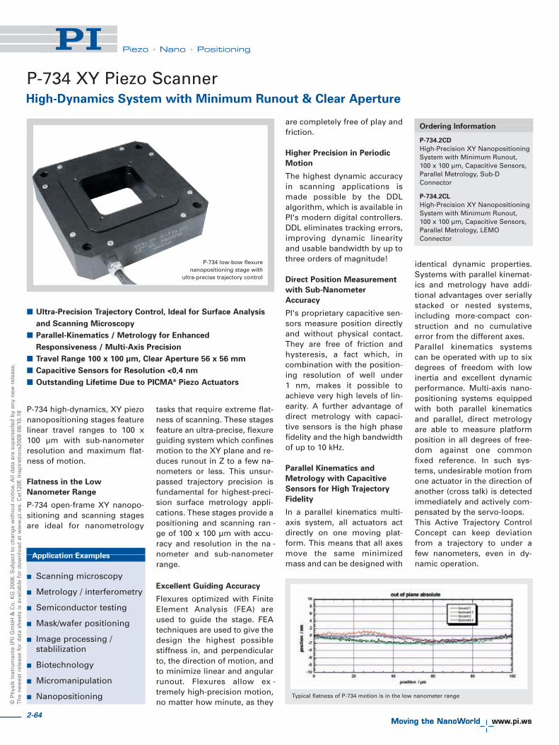
© P
hys
ik In
stru
men
te (
PI)
Gm
bH
& C
o. K
G 2
008.
Su
bje
ct t
o c
han
ge
wit
ho
ut
no
tice
. All
dat
a ar
e su
per
sed
ed b
y an
y n
ew r
elea
se.
Th
e n
ewes
t re
leas
e fo
r d
ata
shee
ts is
ava
ilab
le f
or
do
wn
load
at
ww
w.p
i.ws.
Cat
120E
Insp
irat
ion
s200
9 08
/10.
18
Piezo • Nano • Positioning
P-734 high-dynamics, XY piezonanopositioning stages featurelinear travel ranges to 100 x100 μm with sub-nanometerresolution and maximum flat-ness of motion.
Flatness in the Low
Nanometer Range
P-734 open-frame XY nanopo-sitioning and scanning stagesare ideal for nanometrology
tasks that require extreme flat-ness of scanning. These stagesfeature an ultra-precise, flexureguiding system which confinesmotion to the XY plane and re -duces runout in Z to a few na -no meters or less. This un sur -passed trajectory precision isfun damental for highest-preci-sion surface metrology appli-cations. These stages provide apositioning and scanning ra n -ge of 100 x 100 μm with accu-ra cy and resolution in the na -no meter and sub-nanometerrange.
Excellent Guiding Accuracy
Flexures optimized with FiniteElement Analysis (FEA) areused to guide the stage. FEAtechniques are used to give thedesign the highest possiblestiffness in, and perpendicularto, the direction of motion, andto minimize linear and angularrunout. Flexures allow ex -tremely high-precision motion,no matter how minute, as they
are completely free of play andfriction.
Higher Precision in Periodic
Motion
The highest dynamic accuracyin scanning applications ismade possible by the DDLalgorithm, which is available inPI's modern digital controllers.DDL eliminates tracking errors,improving dynamic linearityand usable bandwidth by up tothree orders of magnitude!
Direct Position Measurement
with Sub-Nanometer
Accuracy
PI's proprietary capacitive sen-sors measure position directlyand without physical contact.They are free of friction andhysteresis, a fact which, incom bination with the position-ing resolution of well under 1 nm, makes it possible toachieve very high levels of lin-earity. A further advantage ofdirect metrology with capaci-tive sensors is the high phasefidelity and the high bandwidthof up to 10 kHz.
Parallel Kinematics and
Metrology with Capacitive
Sensors for High Trajectory
Fidelity
In a parallel kinematics multi-axis system, all actuators actdirectly on one moving plat-form. This means that all axesmove the same minimizedmass and can be designed with
identical dynamic properties.Systems with parallel kinemat-ics and metrology have addi-tional advantages over seriallystacked or nested systems,including more-compact con-struction and no cumulativeerror from the different axes. Parallel kinematics systemscan be operated with up to sixdegrees of freedom with lowinertia and excellent dynamicperformance. Multi-axis nano -positioning systems equippedwith both parallel kinematicsand parallel, direct metrologyare able to measure platformposition in all degrees of free-dom against one commonfixed reference. In such sys-tems, undesirable motion fromone actuator in the direction ofanother (cross talk) is detectedimmediately and actively com-pensated by the servo-loops. This Active Trajectory ControlConcept can keep deviationfrom a trajectory to under afew nanometers, even in dy -namic operation.
High-Dynamics System with Minimum Runout & Clear Aperture
P-734 XY Piezo Scanner
Ordering Information
P-734.2CD
High-Precision XY NanopositioningSystem with Minimum Runout, 100 x 100 μm, Capacitive Sensors,Parallel Metrology, Sub-DConnector
P-734.2CL
High-Precision XY NanopositioningSystem with Minimum Runout, 100 x 100 μm, Capacitive Sensors,Parallel Metrology, LEMOConnector
P-734 low-bow flexurenanopositioning stage with
ultra-precise trajectory control
� Ultra-Precision Trajectory Control, Ideal for Surface Analysis
and Scanning Microscopy
� Parallel-Kinematics / Metrology for Enhanced
Responsiveness / Multi-Axis Precision
� Travel Range 100 x 100 μm, Clear Aperture 56 x 56 mm
� Capacitive Sensors for Resolution <0,4 nm
� Outstanding Lifetime Due to PICMA® Piezo Actuators
Application Examples
� Scanning microscopy
� Metrology / interferometry
� Semiconductor testing
� Mask/wafer positioning
� Image processing / stablilization
� Biotechnology
� Micromanipulation
� Nanopositioning Typical flatness of P-734 motion is in the low nanometer range
2-64

2-65
Piezo • Nano • Positioning
Piezo Flexure Stages /High-Speed Scanning Systems
Nanopositioning / Piezoelectrics
Linear Actuators & Motors
Fast Steering Mirrors / Active Optics
Piezo Drivers / Servo Controllers
Piezoelectrics in Positioning
Nanometrology
Micropositioning
Linear
Vertical & Tip/Tilt
2- and 3-Axis
6-Axis
Single-Channel
Multi-Channel
Modular
Accessories
Index
P-734 dimensions in mm
Technical Data
Models P-734.2CL P-734.2CD Units Tolerance
Active axes X, Y X, Y
Motion and positioning
Integrated sensor Capacitive Capacitive
Open-loop travel, -20 to +120 V 110 x 110 110 x 110 μm min. (+20 %/-0 %)
Closed-loop travel 100 x 100 100 x 100 μm
Open-loop resolution 0.2 0.2 nm typ.
Closed-loop resolution 0.3 0.3 nm typ.
Linearity 0.03 0.03 % typ.
Repeatability <2.5 <2.5 nm typ.
Pitch <3 <3 μrad typ.
Yaw <10 <10 μrad typ.
Flatness typ. <5, typ. <5, nm typ.
max. <10 max. <10
Mechanical properties
Stiffness 3 3 N/μm ±20 %
Unloaded resonant frequency 500 500 Hz ±20 %
Resonant frequency @ 200 g 350 350 Hz ±20 %
Resonant frequency @ 500 g 250 250 Hz ±20 %
Push/pull force capacity in motion direction 300 / 100 300 / 100 N Max.
Load capacity 20 20 N Max.
Drive properties
Ceramic type PICMA® P-885 PICMA® P-885
Electrical Capacitance 6.2 6.2 μF ±20%
Dynamic operating current coefficient 7.8 7.8 μA/(Hz • μm) ±20%
Miscellaneous
Operating temperature range -20 to 80 -20 to 80 °C
Material Aluminum Aluminum
Mass (with cables) 1.04 1.04 kg ±5 %
Cable length 1.5 1.5 m ±10 mm
Sensor connection 2x LEMO Sub-D Special
Voltage connection 4x LEMO Sub-D Special
Dynamic Operating CurrentCoefficient in μA per Hz and μm.Example: Sinusoidal scan of 10 μm at 10 Hz requires approxi-mately 7.8 mA drive current.
Recommended controller /amplifierP-734.2CL (p. 2-64): E-500 modu-lar piezo controller system (p. 2-142) with amplifier moduleE-503 (three channels) (p. 2-146)or E-505 (1 per axis, high perfor-mance) (p. 2-147) and E-509 controller (p. 2-152)P-734.2CD (p. 2-64): Multi-channel digital controllers: E-710/E-725 bench-top (p. 2-128,p. 2-126), E-712 modular (p. 2-140),E-761 PCI board (p. 2-130)
Ceramic Insulated Piezo
Actuators Provide Long
Lifetime
Highest possible reliability isassured by the use of award-winning PICMA® multilayerpiezo actuators. PICMA® actua-tors are the only actuators onthe market with ceramic-onlyinsulation, which makes themresistant to ambient humidityand leakage-current failures.They are thus far superior toconventional actuators in relia-bility and lifetime.

2-66
© P
hys
ik In
stru
men
te (
PI)
Gm
bH
& C
o. K
G 2
008.
Su
bje
ct t
o c
han
ge
wit
ho
ut
no
tice
. All
dat
a ar
e su
per
sed
ed b
y an
y n
ew r
elea
se.
Th
e n
ewes
t re
leas
e fo
r d
ata
shee
ts is
ava
ilab
le f
or
do
wn
load
at
ww
w.p
i.ws.
Cat
120E
Insp
irat
ion
s200
9 08
/10.
18
Piezo • Nano • Positioning
High-Dynamics Nanoscanner for Scanning Probe Microscopy
P-363 PicoCube™ XY(Z) Piezo Scanner
The P-363 PicoCube™ XY/XYZis an ultra-high-performanceclosed-loop piezo scanningsystem. Designed for AFM,SPM and nanomanipulationapplications, it combines anultra-low inertia, high-speedXY/XYZ piezo scanner withnon-contact, direct-measuring,parallel-metrology capacitivefeedback capable of 50 pico me-ters resolution. On top of beingextremely precise, thePicoCube™ system is also verysmall and rugged. Measuring
only 30 x 30 x 40 mm (withremovable top plate, 30 x 30 x28 mm for XY version), it iseasy to integrate in any scan-ning apparatus.
SPM, AFM, STM, Nano-
lithography, Nanoimprinting,
Nanometrology
The PicoCube™ was specifical-ly developed to overcome thelimitations of the open-loopscanners currently available forSPM, AFM and STM. In addi-tion to these applications, thePicoCube™ is also the idealscanning and manipulationtool for nanoimprinting, nano-lithography, ultra-high-resolution, near-field, scanningoptical microscopy and nano-surface-metrology applica-tions.
Higher Precision Through
Parallel-Motion Metrology w/
Capacitive Sensors
The PicoCube™ is based on aproprietary, ultra-fast, piezo-driven scanner design equip -
ped with direct-measuring, ca -pacitive position sensors (par-allel metrology). Unlike con-ventional sensors, they meas-ure the actual distance be -tween the fixed frame and themoving part of the stage. Thisresults in higher-motion linear-ity, long-term stability, phasefidelity, and—because externaldisturbances are seen by thesensor immediately—a stiffer,faster-responding servo-loop.
Multi-axis nanopositioningsystems equipped with paralleldirect metrology are able tomeasure the platform positionin all degrees of freedomagainst one fixed reference. Insuch systems, undesirablemotion from one actuator inthe direction of another (cross-talk) is detected immediatelyand act iv ely compensated bythe servo-loops. This ActiveTra jectory Control Concept cankeep deviation from a trajecto-ry to under a few nanometers,even in dynamic operation.
� Ultra-High-Performance Closed-Loop Scanner for AFM/SPM
� Compact Manipulation Tool for Bio/Nanotechnology
� Resonant Frequency 9.8 kHz
� Capacitive Sensors for Highest Accuracy
� Parallel-Motion Metrology for Automated Compensation
of Guiding Errors
� 50 Picometer Resolution
� 5 x 5 x 5 μm Travel Range
� Vacuum-Compatible Versions
P-363.2CD and .3CD (background)PicoCube™, high-performancepiezo positioning- and scanningsystems or AFM/STM andnanomanipulation. Smart mediacard for size comparison
Application Examples
� Scanning microscopy(SPM)
� Biotechnology
� Micromanipulation
� Nanopositioning
� Nano-imprinting
� Nanometrology
� Nanolithography
Ordering Information
P-363.3CD
PicoCube™ High-Precision XYZNanopositioning System, 5 x 5 x 5 μm, Parallel Metrology,Capacitive Sensors, Sub-DConnector
P-363.3UD
PicoCube™ High-Precision XYZNanopositioning System, 5 x 5 x 5 μm, Parallel Metrology,Capacitive Sensors, Sub-DConnector, Vacuum Compatible to 10-9 hPa
P-363.2CD
PicoCube™ High-Precision XYNanopositioning System, 5 x 5 μm,Parallel Metrology, CapacitiveSensors, Sub-D Connector
P-363.2UD
PicoCube™ High-Precision XYNanopositioning System, 5 x 5 μm,Parallel Metrology, CapacitiveSensors, Sub-D Connector, VacuumCompatible to 10-9 hPa
P-363.3CL
PicoCube™ High-Precision XYZNanopositioning System, 5 x 5 x 5 μm, Parallel Metrology,Capacitive Sensors, LEMOConnector
P-363.2CL
PicoCube™ High-Precision XYNanopositioning System, 5 x 5 μm,Parallel Metrology, CapacitiveSensors, LEMO Connector
300 picometersteps (0.3 nm)performed withthe P-363, meas-ured with anexternal high-resolution,capacitive meas-urement system
The P-363 settlesto within 1 nm in1 ms (100 nmstep, X and Ymotion; fasterresponse in Z)
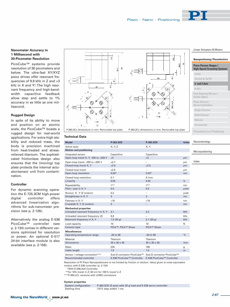
2-67
Piezo • Nano • Positioning
Piezo Flexure Stages /High-Speed Scanning Systems
Nanopositioning / Piezoelectrics
Linear Actuators & Motors
Fast Steering Mirrors / Active Optics
Piezo Drivers / Servo Controllers
Piezoelectrics in Positioning
Nanometrology
Micropositioning
Linear
Vertical & Tip/Tilt
2- and 3-Axis
6-Axis
Single-Channel
Multi-Channel
Modular
Accessories
Index
P-363.2Cx dimensions in mm. Removable top plateP-363.3Cx dimensions in mm. Removable top plate
Technical Data
Model P-363.3CD P-363.2CD Units
Active axes X, Y, Z X, YMotion and positioning
Integrated sensor Capacitive CapacitiveOpen-loop travel X, Y, -250 to +250 V ±3 ±3 μm
Open-loop travel, -250 to +250 V ±2.7 – μmClosed-loop travel X, Y ±2.5 ±2.5 μm
Closed-loop travel ±2.5 – μmOpen-loop resolution 0.03* 0.03* nm
Closed-loop resolution 0.1 0.1nmLinearity 0.05 0.05 %
Repeatability 1** 1** nmPitch / yaw in X, Y 0.5 0.5 μrad
Runout X, Y (Z motion) 0.2 – μradStraightness in X, Y 3 3 nm
Flatness in X, Y <10 <10 nmCrosstalk X, Y (Z motion) 5 – nm
Mechanical properties
Unloaded resonant frequency in X, Y 3.1 4.2 kHz
Unloaded resonant frequency (Z) 9.8 – kHzResonant frequency in X, Y 1.5 (20 g) 2.1 (20 g) kHz
Load capacity 10 10 NCeramic type PICA™, PICA™ Shear PICA™ Shear
Miscellaneous
Operating temperature range -20 to 80 -20 to 80 °C
Material Titanium TitaniumDimensions 30 x 30 x 40 30 x 30 x 28 mm
Mass 225 190 gCable length 1.5 1.5 m
Sensor / voltage connection*** Sub-D connector PicoCube™ Sub-D connector PicoCube™Recommended controller E-536 PicoCube™ Controller E-536 PicoCube™ Controller
Resolution of PI Piezo Nanopositioners is not limited by friction or stiction. Value given is noise equivalentmotion with E-536 controller (p. 2-134)
*With E-536.3xH Controller**for 10% travel in Z; 50 nm for 100 % travel in Z
***P-363.xCL versions with LEMO connectors
Nanometer Accuracy in
1 Millisecond with
30-Picometer Resolution
PicoCube™ systems provideresolution of 30 picometers andbelow. The ultra-fast XY/XYZpiezo drives offer resonant fre-quencies of 9.8 kHz in Z and >3kHz in X and Y! The high reso-nant frequency and high-band-width capacitive feed backallow step and settle to 1%accuracy in as little as one mil-lisecond.
Rugged Design
In spite of its ability to moveand position on an atomicscale, the PicoCube™ boasts arugged design for real-worldapplications. For extra-high sta-bility and reduced mass, thebody is precision machinedfrom heat-treated and stress-relieved titanium. The sophisti-cated frictionless design alsoensures that the (moving) topplate protects the internal actu-ator/sensor unit from contami-nation.
Controller
For dynamic scanning opera-tion the E-725.3CM high-powerdigital controller offersadvanced linearization algo-rithms for sub-nanometer pre-cision (see p. 2-126).
Alternatively the analog E-536PicoCube™ controller (see p. 2-134) comes in different ver-sions optimized for resolutionor power. An optional E-517 24-bit interface module is alsoa vailable (see p. 2-156).
System properties
System configuration P-363.3CD (Z-axis) with 20 g load and E-536 servo controllerSettling time (10 % step width) 1 ms

2-68
© P
hys
ik In
stru
men
te (
PI)
Gm
bH
& C
o. K
G 2
008.
Su
bje
ct t
o c
han
ge
wit
ho
ut
no
tice
. All
dat
a ar
e su
per
sed
ed b
y an
y n
ew r
elea
se.
Th
e n
ewes
t re
leas
e fo
r d
ata
shee
ts is
ava
ilab
le f
or
do
wn
load
at
ww
w.p
i.ws.
Cat
120E
Insp
irat
ion
s200
9 08
/10.
18
Piezo • Nano • Positioning
The P-615 NanoCube® is amulti-axis piezo nanoposition-ing and alignment system. Its420 x 420 x 300 μm, XYZ posi-tioning and scanning rangecomes in a compact package.Equipped with a zero-stiction,zero-friction guidance system,this NanoCube® provides mo -tion with ultra-high resolutionand settling times of only a fewmilliseconds.
Fiber Positioning
The P-615 NanoCube® is equip -ped with a fiber adapter inter-
face similar to the P-611.3SFand accommodates all F-603-series fiber holders and acces-sories. Fiber optics handling isfacilitated by the clear aper-ture.
Double Stiffness for Fast
Response
The P-615's unique flexuredesign has double the stiffnessin the vertical axis than in Xand Y, providing faster res -ponse and higher operatingfrequencies under load. Forexample, the settling time toreach a commanded positionwith 1 % accuracy is only 15 msin the Z-axis with 100 g load (asopposed to 10 ms withoutload).
Open-Loop and Closed-Loop
Operation
The open-loop basic model P-615.30L is ideal for appli ca-
tions where fast response andvery high resolution are essen-tial but specifying or reportingabsolute position values iseither not required or is han-dled by external sensors, e. g.in tracking or fiber positioningtasks. In open-loop mode, thepiezo displacement is roughlyproportional to the appliedvoltage (see p. 2-184).
Capacitive Sensors for Highest
Accuracy
The P-615.3C models areequipped with high-accuracy,capacitive position sensors.PI's proprietary capacitive sen-sors measure position directlyand without physical contact.They are free of friction andhysteresis, a fact which, incombination with the position-ing resolution of well under 1 nm, makes it possible toachieve very high levels of lin-earity. A further advantage ofdirect metrology with capaci-tive sensors is the high phasefidelity and the high bandwidthof up to 10 kHz.
Active and Passive Guidance
for Nanometer Flatness and
Straightness
Wire-cut flexures optimizedwith Finite Element Analysis(FEA) are used to guide thestage. The FEA techniques givethe design the highest possiblestiffness and minimize linearand angular runout. Furtherenhancement is achieved byactive trajectory control: multi-axis nanopositioning systemsequipped with parallel metrol-ogy are able to measure plat-form position in all degrees offreedom against a common,fixed reference. In such sys-tems, undesirable motion fromone actuator in the direction ofanother (cross-talk) is detectedimmediately and actively com-pensated by the servo-loops.This can keep deviation from a
trajectory to under a fewnanometers, even in dynamicoperation.
Ceramic Insulated Piezo
Actuators Provide Long
Lifetime
Highest possible reliability isassured by the use of award-winning PICMA® multilayerpiezo actuators. PICMA® actua-tors are the only actuators onthe market with ceramic-onlyinsulation, which makes themresistant to ambient humidityand leakage-current failures.They are thus far superior toconventional actuators in relia-bility and lifetime.
Long-Travel Multi-Axis Piezo Stage for Precision Alignment Applications
P-615 NanoCube® XYZ Piezo System
� Up to 420 x 420 x 300 μm Travel Range
� Resolution 1 nm
� Parallel-Kinematics / Metrology for Enhanced Responsiveness
/ Multi-Axis Precision
� Clear Aperture of 10 mm Ø, Ideal for Alignment and
Photonics Packaging Applications
� Outstanding Lifetime Due to PICMA® Piezo Actuators
� Open- & Closed-Loop Versions
� Vacuum-Compatible Versions to 10-9 hPa
� Frictionless, High-Precision Flexure Guiding System
Application Examples
� Micromanipulation
� Biotechnology
� Semiconductor testing
� Photonics / integratedoptics
Ordering Information
P-615.3CD
NanoCube® XYZ NanopositioningSystem with Long Travel Range,350 x 350 x 250 μm, ParallelMetrology, Capacitive Sensors,Sub-D Connector
P-615.3CL
NanoCube® XYZ NanopositioningSystem with Long Travel Range,350 x 350 x 250 μm, ParallelMetrology, Capacitive Sensors,LEMO Connector
P-615.30L
NanoCube® XYZ NanopositioningSystem with Long Travel Range,420 x 420 x 300 μm, ParallelMetrology, Open-Loop, LEMOConnector
P-615.3UD
NanoCube® XYZ NanopositioningSystem with Long Travel Range,350 x 350 x 250 μm, ParallelMetrology, Capacitive Sensors,Sub-D Connector, VacuumCompatible to 10-9 hPa
P-615NanoCube® XYZ Nanopositioning System providesup to 420 x 420 x 300 μm travel range

2-69
Piezo • Nano • Positioning
Piezo Flexure Stages /High-Speed Scanning Systems
Nanopositioning / Piezoelectrics
Linear Actuators & Motors
Fast Steering Mirrors / Active Optics
Piezo Drivers / Servo Controllers
Piezoelectrics in Positioning
Nanometrology
Micropositioning
Linear
Vertical & Tip/Tilt
2- and 3-Axis
6-Axis
Single-Channel
Multi-Channel
Modular
Accessories
Index
Resolution of PI PiezoNanopositioners is not limited byfriction or stiction. Value given isnoise equivalent motion with E-503 amplifier (p. 2-146).
Recommended controllerMulti-channel digital controllers: E-710 bench-top (p. 2-128), E-712modular (p. 2-140), E-725 high-power (p. 2-126), E-761 PCI board(p. 2-130)Multi-channel: E-500 modular piezo controllersystem (p. 2-142) with E-509 servo-controller (p. 2-152) (optional) andas amplifier either E-503 (threechannels) (p. 2-146) or E-505 (1 per axis, high-power, p. 2-147)modules P-615.30L (p. 2-68): E-610controller / amplifier (p. 2-110)(1 per axis)
P-615, X-axis with 100 g load performing 100 nm steps in rapid sequence without overshoot. Settling time for the Z-axis to reach a commanded position with 1 % accuracy is only 15 ms.
Technical Data
Model P-615.3CD / P-615.30L Units ToleranceP-615.3CL
Active axes X, Y, Z X, Y, Z
Motion and positioning
Integrated sensor Capacitive –
Open-loop travel in X/Y/Z, -20 to +120 V 420 / 420 / 300 420 / 420 / 300 μm min. (+20 %/-0 %)
Closed-loop travel X/Y/Z 350 / 350 / 250 – μm
Open-loop resolution X/Y/Z 0.5 0.5 nm typ.
Closed-loop resolution X/Y/Z 1 – nm typ.
Linearity X/Y/Z 0.02 – % typ.
Repeatability in X, Y, Z ±7.5 / ±7.5 / ±5 – nm typ.
Pitch in X,Y 100 100 μrad typ.
Yaw in X, Y 50 50 μrad typ.
Runout θX, θY (Z motion) 10 10 μrad typ.
Mechanical properties
Stiffness X / Y / Z 0.13 / 0.13 / 0.35 0.13 / 0.13 / 0.35 N/μm ±20 %
Unloaded resonant frequency in X / Y / Z 210 / 210 / 250 210 / 210 / 250 Hz ±20 %
Resonant frequency @ 100 g in X / Y / Z 125 / 125 / 200 125 / 125 / 200 Hz ±20 %
Push/pull force capacity in motion direction 20 / 10 20 / 10 N Max.
Load capacity 20 20 N Max.
Drive properties
Ceramic type PICMA® P-885 PICMA® P-885
Electrical capacitance in X / Y / Z 3.7 / 3.7 / 6.2 3.7 / 3.7 / 6.2 μF ±20 %
Dynamic operating current coefficient 1.3 / 1.3 / 3.1 1.3 / 1.3 / 3.1 μA/(Hz·μm) ±20 %
(DOCC) in X / Y / Z
Miscellaneous
Operating temperature range -20 to 80 -20 to 80 °C
Material Aluminum Aluminum
Mass 0.58 0.57 kg ±5 %
Cable length 1.5 1.5 m ±10 mm
Sensor / voltage connection Sub-D special LEMO
(CD-version); (no sensor)
LEMO (CL-version)
P-615 dimensions in mm. The clear aperture has a diameter of 10 mm.
P-615 with optional fiber holder F-603.22

© P
hys
ik In
stru
men
te (
PI)
Gm
bH
& C
o. K
G 2
008.
Su
bje
ct t
o c
han
ge
wit
ho
ut
no
tice
. All
dat
a ar
e su
per
sed
ed b
y an
y n
ew r
elea
se.
Th
e n
ewes
t re
leas
e fo
r d
ata
shee
ts is
ava
ilab
le f
or
do
wn
load
at
ww
w.p
i.ws.
Cat
120E
Insp
irat
ion
s200
9 08
/10.
18
Piezo • Nano • Positioning
P-517 and P-527 high-dynam-ics, multi-axis piezo-nanoposi-tioning stages are available inXY ΘZ, XY and XYZ configura-tions featuring linear travelranges to 200 x 200 x 20 μmand rotation ranges to 4 mrad.The 66 x 66 mm clear apertureis ideal for transmitted-lightapplications. Z/tip/tilt versions in the sameform factor are also offered asmodels P-518, P-528, P-558 (see p. 2-46) and as customversions with up to six degreesof freedom.
Capacitive Sensors for Highest
Accuracy
PI's proprietary capacitive sen-sors measure position directlyand without physical contact.They are free of friction andhysteresis, a fact which, incombination with the position-
ing resolution of well under 1 nm, makes it possible toachieve very high levels of lin-earity. A further advantage ofdirect metrology with capaci-tive sensors is the high phasefidelity and the high bandwidthof up to 10 kHz.
Technical Data
Models P-517.2CL P-527.2CL P-517.3CL/ P-527.3CL/ P-517.RCD P-527.RCD
P-517.3CD P-527.3CD
Active axes X, Y X, Y X, Y, Z X, Y, Z X, �Y, �Z �Y, �Z
Motion and positioning
Integrated sensor Capacitive Capacitive Capacitive Capacitive Capacitive Capacitive
Open-loop travel, -20 to +120 V 130 250 130; Z: 25 250; Z: 25 130; �Z: ±1.3 mrad 250; �Z: ±2.5 mrad
Closed-loop travel 100 200 100; Z: 20 200; Z: 20 100; �Z: ± 1 mrad 200; �Z: ± 2 mrad
Open-loop resolution 0.3 0.5 0.3; Z: 0.1 0.5; Z: 0.1 0.3; �Z: 0.1 μrad 0.5; �ZZ: 0.1 μrad
Closed-loop resolution 1 2 1; Z: 0.1 2; Z: 0.1 1; �Z: 0.3 μrad 2; �Z: 0.3 μrad
Linearity 0.03 0.03 0.03 0.03 0.03 0.03
Repeatability ±5 ±10 ±5; Z: ±1 ±10; Z: ±1 ±5; Z: ±0.5 μrad ±10
Mechanical properties
Stiffness 2 1 2; Z: 15 1; Z: 15 2 1
Unloaded resonant frequency 450 350 450; Z: 1100 350; Z: 1100 450; Z: 400 350; Z: 300
Resonant frequency @ 500 g X, Y 250 190 250 190 250 190
Resonant frequency @ 2500 g X, Y 140 110 140 110 140 110
Push/pull force capacity in motion direction 50 / 30 50 / 30 50 / 30 50 / 30 50 / 30 50 / 30
Drive properties
Ceramic type PICMA® P-885 PICMA® P-885 PICMA® P-885 PICMA® P-885 PICMA® P-885 PICMA® P-885
Electrical capacitance 9.2 9.2 9; Z: 6 9; Z: 6 9 9
Dynamic operating current coefficient (DOCC) 11.5 5.8 11.5; Z: 37 5.5; Z: 37 11.5 5.5
Miscellaneous
Operating temperature range -20 to 80 -20 to 80 -20 to 80 -20 to 80 -20 to 80 -20 to 80
Material Aluminum Aluminum Aluminum Aluminum Aluminum Aluminum
Mass 0.14 0.14 0.145 0.145 0.14 0.14
Sensor / voltage connection LEMO LEMO Sub-D special ; Sub-D special Sub-D Special Sub-D Special(CD-version) (CD-version)LEMO (CL-version) LEMO (CL-version)
Resolution of PI Piezo Nanopo si tioners is not limited by friction or stiction. Value given is noise equivalent motion with E -503 or E-710 controller (p. 2-146 or p. 2-128)Linear Dynamic Operating Current Coefficient in μA per Hz and μm. Example for P-527.2xx: Sinusoidal scan of 30 μm at 10 Hz requires approximately 1.8 mA drive current (p. 2-70). Electrical capacitance and DOCC of the rotatiostated. Recommended controllerVersions with LEMO connectors: Single-channel (1 per axis): E-610 servo-controller / amplifier (p. 2-110), E-625 servo-controller, bench-top (p. 2-114), E-621 controller module (p. 2-160) Multi-channel: modular piezo controller sy(three channels) (p. 2-146) or E-505 (1 per axis, high-power) (p. 2-147) and E-509 controller (p. 2-152)Versions with Sub-D connectors: Multi-channel digital controllers: E-710 bench-top (p. 2-128), E-712 modular (p. 2-140), E-725 high-power (p. 2-126), E-761 PCI board (p. 2-130)
Application Examples
� Metrology
� Interferometry
� Optics
� Lithography
� Nanopositioning
� Scanning microscopy
� Mass storage device testing
� Laser technology
� Micromachining
High-Dynamics Nanopositioner / Scanner with Direct Position Metrology
P-517 · P-527 Multi-Axis Piezo Scanner
P-527.2CL parallel-kinematic nanopositioning system
� Travel Ranges to 200 μm
� Sub-Nanometer Resolution
� Frictionless, High-Precision Flexure Guiding System
� Capacitive Sensors for Highest Linearity
� Parallel-Kinematics / Metrology for Enhanced
Responsiveness / Multi-Axis Precision
� Clear Aperture 66 x 66 mm
� Outstanding Lifetime Due to PICMA® Piezo Actuators
2-70

2-71
Piezo • Nano • Positioning
Piezo Flexure Stages /High-Speed Scanning Systems
Nanopositioning / Piezoelectrics
Linear Actuators & Motors
Fast Steering Mirrors / Active Optics
Piezo Drivers / Servo Controllers
Piezoelectrics in Positioning
Nanometrology
Micropositioning
Linear
Vertical & Tip/Tilt
2- and 3-Axis
6-Axis
Single-Channel
Multi-Channel
Modular
Accessories
Index
Active and Passive Guidance
for Nanometer Flatness and
Straightness
Flexures optimized with FiniteElement Analysis (FEA) areused to guide the stage. TheFEA techniques provide for thehighest possible stiffness in,and perpendicular to, the direc-tion of motion, and minimizelinear and angular runout.Flexures allow extremely high-precision motion, no matterhow minute, as they are com-pletely free of play and friction.Due to the parallel kinematicsdesign there is only one com-mon moving platform for allaxes, minimizing mass,enabling identical dynamicbehavior and eliminatingcumulative errors. Parallelkinematics also allows for amore compact constructionand faster response compared
to stacked or nested designs.The high precision due to flex-ure guidance is furtherenhanced by Active TrajectoryControl: Multi-axis nanoposi-tioning systems equipped withboth parallel kinematics andparallel direct metrology areable to measure platform posi-tion in all degrees of freedomagainst one common fixed ref-erence. In such systems, unde-sirable motion from one actua-tor in the direction of another(cross-talk) is detected immedi-ately and actively compensat-ed by the servo-loops. ThisActive Trajectory ControlConcept can keep deviationfrom a trajectory to under afew nanometers, even indynamic operation.
Ceramic Insulated Piezo
Actuators Provide Long
Lifetime
Highest possible reliability isassured by the use of award-winning PICMA® multilayerpiezo actuators. PICMA® actua-tors are the only actuators onthe market with ceramic-onlyinsulation, which makes themresistant to ambient humidityand leakage-current failures.They are thus far superior toconventional actuators in relia-bility and lifetime.
Units Tolerance
μm min.(+20%/0%)
μm
nm typ.
nm typ.
% typ.
nm typ.
N/μm ±20%
Hz ±20%
Hz ±20%
Hz ±20%
N Max.
μF ±20%
μA/(Hz • μm) ±20%
°C
kg ±5%
on axes base upon differential motion in X, Y; therefore not
ystem E-500 (p. 2-142) with amplifier module E-503
Ordering Information
P-517.2CL
Precision XY NanopositioningSystem, 100 x 100 μm, CapacitiveSensors, Parallel Metrology, LEMOConnector
P-527.2CL
Precision XY NanopositioningSystem, 200 x 200 μm, CapacitiveSensors, Parallel Metrology, LEMOConnector
P-517.3CL
Precision XYZ NanopositioningSystem, 100 x 100 x 20 μm,Capacitive Sensors, ParallelMetrology, LEMO Connector
P-517.3CD
Precision XYZ NanopositioningSystem, 100 x 100 x 20 μm,Capacitive Sensors, ParallelMetrology, Sub-D Connector
P-527.2CL
Precision XY NanopositioningSystem, 200 x 200 μm, CapacitiveSensors, Parallel Metrology, LEMOConnector
P-527.3CD
Precision XYZ NanopositioningSystem, 200 x 200 x 20 μm,Capacitive Sensors, ParallelMetrology, Sub-D Connector
P-517.RCD
Precision XY / rotation nanoposi-tioning system, 100 x 100 μm, 2 mrad, Capacitive Sensors, ParallelMetrology, Sub-D Connector
P-527.RCD
Precision XY / rotation nanoposi-tioning system, 200 x 200 μm, 4 mrad, Capacitive Sensors, ParallelMetrology, Sub-D Connector
P-517, P-527 dimensions in mm, cable length 1.5 m

2-72
© P
hys
ik In
stru
men
te (
PI)
Gm
bH
& C
o. K
G 2
008.
Su
bje
ct t
o c
han
ge
wit
ho
ut
no
tice
. All
dat
a ar
e su
per
sed
ed b
y an
y n
ew r
elea
se.
Th
e n
ewes
t re
leas
e fo
r d
ata
shee
ts is
ava
ilab
le f
or
do
wn
load
at
ww
w.p
i.ws.
Cat
120E
Insp
irat
ion
s200
9 08
/10.
18
Piezo • Nano • Positioning
PIMars™ open-frame piezosta ges are fast and highly accu-rate multi-axis scanning andnanopositioning systems withflatness and straightness in thenanometer range.
The 66 x 66 mm clear apertureis ideal for transmitted-lightapplications such as near-fieldscanning or confocal micro -scopy and mask positioning.
Large Variety of Models
PIMars™ multi-axis nanoposi-tioners are offered in a large
variety of configurations.Stand ard models include long-tra vel systems (to 300 x 300 x300 μm), high-speed and vacu-um versions. Custom six-axisdesigns with rotation to 6 mradare available on request.
PI offers versions speciallydesigned for applications inultra-high vacuum with vacu-um-qualified components only.The integrated ceramic-encap-sulated PICMA® actuatorsallow high bakeout tempera-tures and assure minimal out-gassing rates. A non-magnetiza-ble version is available onrequest.
Direct Drive for Ultra-Fast
Scanning and Positioning
The P-561.3DD versions haveresonant frequencies to 1.0 kHz, enabling millisecondscan ning rates with sub-nanometer resolution.
Capacitive Sensors for Highest
Accuracy and Position
Stability
PI's proprietary capacitive sen-sors measure position directlyand without physical contact.They are free of friction andhysteresis, a fact which, incombination with the position-ing resolution of well under 1 nm, makes it possible toachieve very high levels of lin-earity. A further advantage ofdirect metrology with capaci-tive sensors is the high phasefidelity and the high bandwidthof up to 10 kHz.
Active and Passive Guidance
for Nanometer Flatness and
Straightness
Wire-cut flexures optimizedwith Finite Element Analysis(FEA) are used to guide thestage. The FEA techniques givethe design the highest possiblestiffness and minimize linearand angular runout. Furtheren hancement is achieved byactive trajectory control: multi
Application Examples
� Scanning microscopy
� Mask/wafer positioning
� Interferometry
� Metrology
� Biotechnology
� Micromanipulation
High-Precision Nanopositioning Stage, 3 to 6 Axes
P-561 · P-562 · P-563 PIMars™ XYZ Piezo System
P-562 PIMars™ multi-axis, parallel-kinematics nanopositioning stages are avail-able with up to 340 μm travel per axis. Custom versions to 6 DOF are available
� Parallel-Kinematics / Metrology for
Enhanced Responsiveness / Multi-Axis Precision
� Travel Ranges to 340 x 340 x 340 μm
� Capacitive Sensors for Highest Linearity
� Frictionless, High-Precision Flexure Guiding System
� Excellent Scanning Flatness
� High-Dynamics XYZ Version Available;
Custom Versions to 6-DOF
� Clear Aperture 66 x 66 mm
� Outstanding Lifetime Due to PICMA® Piezo Actuators
� UHV Versions to 10-9 hPa
Ordering Information
P-561.3CD
PIMars™ XYZ Piezo-Nano -positioning System, 100 x 100 x 100 μm, ParallelMetrology
P-562.3CD
PIMars™ XYZ Piezo-Nano -positioning System, 200 x 200 x 200 μm, ParallelMetrology
P-563.3CD
PIMars™ XYZ Piezo-Nanopositioning System, 300 x 300 x 300 μm, ParallelMetrology
P-561.3DD
PIMars™ High-Dynamics XYZNanopositioning System,45 x 45 x 15 μm, Parallel
Metrology, Direct Drive
Vacuum-compatible versions to
10-6 hPa for the P-561.3CD,
P-562.3CD and P-563.3CD models
are available as P-561.3VD,
P-562.3VD and P-563.3VD;
versions to 10-9 hPa as P-561.3UD,
P-562.3UD and P-563.3UD.
Super-invar & titanium versions
are available, 6-DOF versions on
request.
P-561, P-562, P-562 dimensions in mm
System properties
System Configuration P-561.3CD with E-710 digital controller, 330 g load
Amplifier bandwidth, small signal 25 Hz in X, Y; 35 Hz in Z
Settling time (10 % step) 20 ms

2-73
Piezo • Nano • Positioning
Piezo Flexure Stages /High-Speed Scanning Systems
Nanopositioning / Piezoelectrics
Linear Actuators & Motors
Fast Steering Mirrors / Active Optics
Piezo Drivers / Servo Controllers
Piezoelectrics in Positioning
Nanometrology
Micropositioning
Linear
Vertical & Tip/Tilt
2- and 3-Axis
6-Axis
Single-Channel
Multi-Channel
Modular
Accessories
Index
Technical Data
Model P-561.3CD P-562.3CD P-563.3CD P-561.3DD Units Tolerance
Active axes X, Y, Z X, Y, Z X, Y, Z X, Y, Z
Motion and positioning
Integrated sensor Capacitive Capacitive Capacitive Capacitive
Open-loop travel, -20 to +120 V 150 x 150 x 150 300 x 300 x 300 340 x 340 x 340 58 x 58 x 18 μm min. (+20 %/0 %)
Closed-loop travel 100 x 100 x 100 200 x 200 x 200 300 x 300 x 300 45 x 45 x 15 μm
Open-loop resolution 0.2 0.4 0.5 0.1 nm typ.
Closed-loop resolution 0.8 1 2 0.2 nm typ.
Linearity 0.03 0.03 0.03 0.01* % typ.
Repeatability in X, Y, Z 2 / 2 / 2 2 / 2 / 4 2 / 2 / 4 2 / 2 / 2 nm typ.
Pitch in X,Y ±1 ±2 ±2 ±3 μrad typ.
Runout �x, �y (Z motion) ±15 ±20 ±25 ±3 μrad typ.
Yaw in X, Y ±6 ±10 ±10 ±3 μrad typ.
Flatness in X, Y ±15 ±20 ±25 ±10 nm typ.
Crosstalk X, Y (Z motion) ±30 ±50 ±50 ±20 nm typ.
Mechanical properties
Unloaded resonant frequency in X / Y / Z 190 / 190 / 380 160 / 160 / 315 140 / 140 / 250 920 / 920 / 1050** Hz ±20 %
Resonant frequency @ 100 g in X / Y / Z - 145 / 145 / 275 120 / 120 / 215 860 / 860 / 950 Hz ±20 %
Resonant frequency @ 30 g in X / Y / Z 140 / 140 / 300 130 / 130 / 195 110 / 110 / 170 500 / 500 / 470 Hz ±20 %
Push force capacity in motion direction 200 / 200 / 50 120 / 120 / 50 100 / 100 / 50 200 / 200 / 50 N Max.in X / Y / Z
Pull force capacity in motion direction 30 / 30 / 30 30 / 30 / 30 30 / 30 / 30 30 / 30 / 30
in X / Y / Z
Load capacity 50 50 50 50 N Max.
Drive properties
Ceramic type PICMA® P-885 PICMA® P-885 PICMA® P-885 PICMA® P-885 in Z, P-888 in XY
Electrical capacitance in X / Y / Z 5.2 / 5.2 / 10.4 7.4 / 7.4 / 14.8 7.4 / 7.4 / 14.8 38 / 38 / 6 μF ±20 %
Dynamic operating current coefficient 6.5 / 6.5 / 13 4.6 / 4.6 / 9.25 3.1 / 3.1 / 6.1 106 / 106 / 50 μA/ ±20 %(DOCC) in X / Y / Z (Hz • μm)
Miscellaneous
Operating temperature range -20 to 80 -20 to 80 -20 to 80 -20 to 80 °C
Material Aluminum Aluminum Aluminum Aluminum
Mass 1.45 1.45 1.45 1.55 kg ±5 %
Cable length 1.5 1.5 1.5 1.5 m ±10 mm
Sensor / voltage connection Sub-D Special Sub-D Special Sub-D Special Sub-D Special
Resolution of PI Piezo Nanopositioners is not limited by friction or stiction. Value given is noise equivalent motion with E-710 (p. 2-128) controller.*With digital controller. Non-linearity of direct drive stages measured with analog controllers is typically up to 0.1 %.
Recommended controller
Multi-channel digital controllers: E-710 bench-top (p. 2-128), E-712 modular (p. 2-140), E-725 high-power (p. 2-126), E-761 PCI board (p. 2-130)
P-562.3CD (unloaded) step and settle isfaster than 10 ms in X, Y and Z
axis nanopositioning systemsequipped with parallel metrolo-gy are able to measure plat-form position in all degrees offreedom against a common,fix ed reference. In such sys-tems, undesirable motion fromone actuator in the direction ofanother (cross-talk) is detectedimmediately and actively com-pensated by the servo-loops.This can keep deviation from atrajectory to under a few nano -meters, even in dynamic opera-tion.

2-74
Piezo • Nano • Positioning
P-915K XY-Theta-Z Piezo Stage3 Degrees of Freedom in the XY Plane
� Travel Ranges 250 x 250 μm, 16 mrad
� Frictionless, High-Precision Flexure Guiding System
� High Stiffness >1 N/μm
� Outstanding Lifetime Due to PICMA® Piezo Actuators
P-313 PicoCube™ XY(Z) Piezo ScannerPicometer Precision, High Bandwidth, No Servo Lag, for Scanning Probe Microscopy
� Ultra-High-Performance Scanner for AFM/SPM
� 20 Picometers Resolution, <1 nm Hysteresis
� Very High Bandwidth with no Servo Lag Due to New Drive
Concept
� Compact Manipulation Tool for Bio-/Nanotechnology
� Resonant Frequency 4.0 kHz (X, Y), 11 kHz (Z)
� 1 x 1 x 0.8 μm Travel Range
P-628K Long-Travel XY Piezo Stage with Nanometer FlatnessNovel Active Z-Axis Design Provides Real Time Runout Compensation
� Closed-Loop Travel Range 800 x 800 μm
(up to 1500 μm Possible)
� Improved Straightness of Travel <1nm
� High-Precision, Cost-Efficient
� Resolution to 0.1 nm, 0.02 % Positioning Accuracy
� Frictionless, High-Precision Flexure Guiding System
� Outstanding Lifetime Due to PICMA® Piezo Actuators
The P-915KPPS is equipped with FEA-modeled flexures forhigher stiffness in all three directions of motion
A new drive concept allows high-linearity positioning in open-loop operation
The P-628KHFS with an active Z-axis
provides an improvedstraightness of
travel with only 9.5 mm added height
compared to an P-628.2 nano positio-
ning stage
Model Travel Resolution Load Settling (system Dimensions
capacity combination
with E-621
P-915KPPS 250 x 250 μm 3 nm 2 kg 45 ms (250 μm) 60 x 60 x 100 mmXY-Rot-Z- ±8 mrad 15 μrad 28 ms (16 mrad)Piezo Stage
Model Travel range (±250 V) Resolution Dimensions
P-313.30 1 x 1 μm (X,Y) 0.02 nm (X, Y) 30 x 30 x 29.4 mmPicoCube™ 0.8 μm (Z) 0.14 nm (Z) Moved platform XYZ Scanner 20 x 20 mm
Model Travel ranges Unload resonant Load capacity Dimensions
frequency
P-628KHFS 800 x 800 μm 75 Hz (X), 10 N 80 x 80 x (9.5 + 30) mmHigh Flatness (X, Y) 105 Hz (Y)XY Stage©
Ph
ysik
Inst
rum
ente
(P
I) G
mb
H &
Co
. KG
200
8. S
ub
ject
to
ch
ang
e w
ith
ou
t n
oti
ce. A
ll d
ata
are
sup
erse
ded
by
any
new
rel
ease
.T
he
new
est
rele
ase
for
dat
a sh
eets
is a
vaila
ble
fo
r d
ow
nlo
ad a
t w
ww
.pi.w
s. C
at12
0E In
spir
atio
ns2
009
08/1
0.18

2-75
Piezo • Nano • Positioning
Piezo Flexure Stages /High-Speed Scanning Systems
Nanopositioning / Piezoelectrics
Linear Actuators & Motors
Fast Steering Mirrors / Active Optics
Piezo Drivers / Servo Controllers
Piezoelectrics in Positioning
Nanometrology
Micropositioning
Linear
Vertical & Tip/Tilt
2- and 3-Axis
6-Axis
Single-Channel
Multi-Channel
Modular
Accessories
Index
P-915K Fast XY Piezo ScannerCost-Effective OEM Slide for Imaging
� For Pixel Sub-Stepping to Enhance Image Resolution
� Compact Design: 40 x 60 x 7 mm
� Highly Cost-Efficient Open-Loop Design
� Travel Ranges to 4 x 4 μm
� Parallel Kinematics for Enhanced Dynamics and Better
Multi-Axis Accuracy
P-915K High-Dynamics XY Piezo ScannerCost-Effective OEM Slide with Large Aperture for Imaging Applications
� Direct Drive for High Dynamics
� Scanning Stage for Pixel Sub-Stepping:
Enhances Image Resolution
� Cost-Efficient Design
� 15 x 15 μm Travel Range
� Load Capacity to 5 N
� Clear Aperture 30 x 45 mm
P-915K Vacuum Compatible XYZ Piezo ScannerLarge Clear Aperture, High-Dynamics, High-Load Nanopositioner
� Vacuum Compatible to 10-6 hPa
� Direct Metrology with Capacitive Sensors
� Excellent Straightness: <0.1 μrad Runout
� Frictionless, High-Precision Flexure Guiding System
� Direct Metrology with Capacitive Sensors
The fast P-915KXYS open-loop XY scanner is ideallysuited for image enhancement e.g. for CCD chips
The P-915KHDS XY scanning stage is drivenby 4 PICMA® piezo actuators to provide high
stiffness, high dynamics and superior lifetime
The P-915KLVS high-dynamics scanner offersa very large clear aperture of 200 x 200 mm
Model Travel range Resolution Resonant frequency Dimensions
P-915KHDS 15 x 15 μm 0.1 nm 1850 Hz Baseplate High-Dynamics 85 x 54 mmXY Scanner Moved platform
69 x 69 mmClear aperture30 x 45 mm
Model Travel Re- Resonant Load Dimensions
solution frequency capacity
P-915KLVS 100 x 100 x 100 μm 1 nm 110 Hz (X,Y) 50 kg 340 x 340 x 60 mmLarge XYZ 230 Hz (Z) Clear apertureScanner 200 x 200 mm
Model Travel Resolution Load capacity Dimensions
P-915KXYS 4 x 4 μm 0.4 nm 50 g 40 x 60 x 7 mmXY Scanner
© P
hys
ik In
stru
men
te (
PI)
Gm
bH
& C
o. K
G 2
008.
Su
bje
ct t
o c
han
ge
wit
ho
ut
no
tice
. All
dat
a ar
e su
per
sed
ed b
y an
y n
ew r
elea
se.
Th
e n
ewes
t re
leas
e fo
r d
ata
shee
ts is
ava
ilab
le f
or
do
wn
load
at
ww
w.p
i.ws.
Cat
120E
Insp
irat
ion
s200
9 08
/10.
18

2-76
© P
hys
ik In
stru
men
te (
PI)
Gm
bH
& C
o. K
G 2
008.
Su
bje
ct t
o c
han
ge
wit
ho
ut
no
tice
. All
dat
a ar
e su
per
sed
ed b
y an
y n
ew r
elea
se.
Th
e n
ewes
t re
leas
e fo
r d
ata
shee
ts is
ava
ilab
le f
or
do
wn
load
at
ww
w.p
i.ws.
Cat
120E
Insp
irat
ion
s200
9 08
/10.
18
Piezo • Nano • Positioning
The P-587.6CD is a unique,highly accurate, 6-axis scan-ning and positioning systembased on piezo flexure drives.It provides a linear travel rangeof 800 x 800 x 200 μm and rota-tion ranges up to 1 mrad.
Direct Position Measurement
with Sub-Nanometer Accuracy
PI's proprietary capacitive sen-sors measure position directlyand without physical contact.They are free of friction andhysteresis, a fact which, incombination with the position-ing resolution of well under 1 nm, makes it possible toachieve very high levels of lin-earity. A further advantage ofdirect metrology with capaci-tive sensors is the high phasefidelity and the high bandwidthof up to 10 kHz.
Excellent Guiding Accuracy
Flexures optimized with FiniteElement Analysis (FEA) are
used to guide the stage. FEAtechniques are used to give thedesign the highest possiblestiffness in, and perpendicularto, the direction of motion, andto minimize linear and angularrunout. Flexures allow extre -mely high-precision motion, nomatter how minute, as they arecompletely free of play andfriction. A flatness and straight-ness in the low nanometerrange is achieved, importantfor surface metrology appli ca-tions.
Parallel Kinematics and
Metrology with Capacitive
Sensors for High Trajectory
Fidelity
In a parallel kinematics multi-axis system, all actuators actdirectly on one moving plat-form. This means that all axesmove the same minimizedmass and can be designed withidentical dynamic properties.Parallel kinematics systemshave additional advantagesover serially stacked systems,including more-compact con-struction and no cumulativeerrors from the individual axes. Multiaxis nanopositioning sys-tems equipped with directmetrology are able to measureplatform position in all degrees
of freedom against one com-mon reference. In such sys-tems, undesirable motion fromone actuator in the direction ofanother (cross-talk) is detectedimmediately and actively com-pensated by the servo-loops.This Active Trajectory ControlConcept can keep deviationfrom a trajectory to under afew nanometers, even indynamic operation.
Automatic Configuration
PI digital piezo controllers andnanopositioning stages withID-Chip can be operated in anycombination, supported by theAutoCalibration function of thecontroller. Individual stagedata and optimized servo-con-trol parameters are stored inthe ID-Chip and are read outautomatically by the digitalcontrollers.
Long Scanning Range, Direct Position Measurement
P-587 6-Axis Precision Piezo Stage
Ordering Information
P-587.6CD
6-Axis Nanopositioning Systemwith Long Travel Range, 800 x 800 x 200 μm, ±0.5 mrad,Parallel Metrology, CapacitiveSensors
Application Examples
� Interferometry
� Metrology
� Nano-imprinting
� Semiconductor testing
� Semiconductor fabrication
� For Surface Metrology, Scanning and Positioning in all Six
Degrees of Freedom
� 800 x 800 x 200 μm Linear Range
� Up to 1 mrad Rotational Range
� Parallel-Kinematics / Metrology for Enhanced
Responsiveness / Multi-Axis Precision
� Direct Metrology with Capacitive Sensors for Highest
Linearity
� Outstanding Lifetime Due to PICMA® Piezo Actuators
� Frictionless, High-Precision Flexure Guiding System
� Active Trajectory Control in All 6 Degrees of Freedom
P-587 piezo-driven parallel-kinematics nanopositioning /scanning stage with E-710.6CD 6-axis digital controller
P-587 dimensions in mm

2-77
Piezo • Nano • Positioning
Piezo Flexure Stages /High-Speed Scanning Systems
Nanopositioning / Piezoelectrics
Linear Actuators & Motors
Fast Steering Mirrors / Active Optics
Piezo Drivers / Servo Controllers
Piezoelectrics in Positioning
Nanometrology
Micropositioning
Linear
Vertical & Tip/Tilt
2- and 3-Axis
6-Axis
Single-Channel
Multi-Channel
Modular
Accessories
Index
Technical Data
Model P-587.6CD Tolerance
Active axes X, Y, Z, θX, θY, θZ
Motion and positioning
Integrated sensor Capacitive
Closed-loop travel X, Y 800 μm
Closed-loop travel 200 μm
Closed-loop tip/tilt angle ±0.5 mrad
Closed-loop θZ angle ±0.5 mrad
Closed-loop / open-loop resolution X, Y 0.9 / 2.2 nm typ.
Closed-loop / open-loop resolution Z 0.4 / 0.7 nm typ.
Closed-loop / open-loop resolution θX, θY 0.05 / 0.1 μrad typ.
Closed-loop / open-loop resolution θZ 0.1 / 0.3 μrad typ.
Linearity X, Y, Z 0.01 % typ.
Linearity θX, θY, θZ 0.1 % typ.
Repeatability X, Y ±3 nm typ.
Repeatability ±2 nm typ.
Repeatability θX, θY ±0.1 μrad typ.
Repeatability θZ ±0.15 μrad typ.
Flatness <15 nm typ.
Mechanical properties
Stiffness X / Y / Z 0.55 / 0.55 / 1.35 N/μm
Unloaded resonant frequency in X / Y / Z 103 / 103 / 235 Hz ±20 %
Resonant frequency @ 500 g in X / Y / Z 88 / 88 / 175 Hz ±20 %
Resonant frequency @ 2000 g in X / Y / Z 65 / 65 / 118 Hz ±20 %
Push/pull force capacity in motion direction 50 / 10 N Max.
Drive properties
Ceramic type PICMA®
Electrical capacitance in X / Y / Z 81 / 81 / 18.4 μF ±20 %
Dynamic operating current coefficient 12.6 μA/(Hz • μm) ±20 %
(DOCC) in X, Y, θZ
Dynamic operating current coefficient 11.5 μA/(Hz • μm) ±20 %
(DOCC) Z, θX, θY
Miscellaneous
Operating temperature range -20 to 80 °C
Material Aluminum
Dimensions 240 x 240 x 50 mm
Mass 7.2 kg ±5 %
Cable length 1.5 m ±10 mm
Sensor / voltage connection 2 x Sub-D Special
Recommended controller / amplifier E-710.6CD (p. 2-128) or
E-712.6CD (p. 2-140)
digital controller
The maximum rotational angle in θZ is 8 mrad, the tilt angles around X and Y rate 3 mrad. Due to parallel kinematics linear motion is not possible when the stage is in extreme position.

2-78
© P
hys
ik In
stru
men
te (
PI)
Gm
bH
& C
o. K
G 2
008.
Su
bje
ct t
o c
han
ge
wit
ho
ut
no
tice
. All
dat
a ar
e su
per
sed
ed b
y an
y n
ew r
elea
se.
Th
e n
ewes
t re
leas
e fo
r d
ata
shee
ts is
ava
ilab
le f
or
do
wn
load
at
ww
w.p
i.ws.
Cat
120E
Insp
irat
ion
s200
9 08
/10.
18
Piezo • Nano • Positioning
Performance specifications arevalid for room temperature (22 ±3 °C) and closed-loop sys-tems are calibrated at this tem-perature (specifications for dif-ferent operating temperatureson request). Recalibration isrecommended for operation ata significantly higher or lowertemperature. Custom designsfor ultra-low or ultra-high temperatures on request.
Integrated feedback sensor
Absolute measuring capacitiveand SGS sensors are used to pro-vide position information to thecontroller. For details see the tuto-rial “Piezoelectrics in Positioning”section (see p. 2-188 ff ).
Open-loop travel for PICMA®
Ceramic Equipped Piezo
Stages and Actuators
Typical open-loop travel at 0 to100 V operating voltage. Max.recommended operating volt-
age range is -20 to +120 V(extremes for short durationsonly).
Open-loop travel for PICA™
Ceramic Equipped Piezo
Actuators
Typical open-loop travel ofhigh-voltage piezo actuators at0 to +1000 V operating voltage.Voltages in excess of +750 Vshould not be applied for longdurations. Operation in therange of -200 to +750 V is rec-ommended for maximum life-time and displacement.
Closed-loop travel for PICMA®
Ceramic Equipped Piezo
Stages and Actuators
Travel provided in closed-loopoperation. PI piezo amplifiershave an output voltage rangeof -20 to +120 V or -30 to +135 Vto provide enough margin forthe servo-controller to compen-sate for load changes, etc.
Open-loop / closed-loop
resolution
Resolution of piezo flexurestages is basically infinitesimalbecause it is not limited by stic-tion or friction. Instead of reso-lution, the noise-equivalentmotion is specified. Values aretypical results (RMS, 1 σ),measured with E-503/E-508)amplifier module in E-500/501chassis.
Full-range repeatability (typ.)
Typical values in closed-loopmode (RMS, 1 σ). Repeatabilityis a percentage of the total dis-tance or angle traveled. Forsmall ranges, repeatability issignificantly better.
Pitch / Yaw / Roll / Rotational
Runout
Typical rotational off-axis error;sometimes associated with aparticular motion axis, as in“Rotational runout (Z motion)”.
Motion and positioning
Notes on Specifications for Piezo Stages, Systems and Actuators
Stiffness
Static large-signal stiffness ofthe stage in operating directionat room temperature. Small-signal stiffness and dynamicstiffness may differ because ofeffects caused by the activenature of piezoelectric material,compound effects, etc. Fordetails see the tutorial“Piezoelectrics in Positioning”section (see p. 2-171 ff ).
Unloaded resonant frequency
Lowest resonant frequency inoperating direction (does notspecify the maximum operat-ing frequency). For details see the tutorial “Piezoelectricsin Positioning” section (see p. 2-171 ff ).
Resonant frequency with load
Resonant frequency of theloaded system.
Push/pull force capacity (in
operating direction)
Specifies the maximum forcesthat can be applied to the sys-tem along the active axis.Limited by the piezoceramicmaterial and the flexure design.If larger forces are applied,damage to the piezoceramic,the flexures or the sensor canoccur. The force limit must alsobe considered in dynamicapplications.
Example: the dynamic forcesgenerated by sinusoidal opera-tion at 500 Hz, 20 μm peak-to-
peak, 1 kg moved mass, areapproximately ±100 N. Fordetails see the tutorial“Piezoelectrics in Positioning”section (see p. 2-171 ff ).
Load capacity
Maximum vertical load, when thestage is mounted horizontally.Limited by the flexures or the loadcapacity of the piezo actuators.
Lateral force limit
Maximum lateral force orthog-onal to the operating direction.Limited by the piezoceramicsand the flexures. For XY stagesthe push/pull force capacity ofthe other module (in its operat-ing direction) limits the lateralforce that can be tolerated.
Mechanical properties
Straightness / Flatness /
Crosstalk
Typical linear off-axis error;sometimes associated with aparticular motion axis, as in“Crosstalk (Z motion)“.
Torque limit (θX, θY, θZ)
Maximum torque that can beapplied to the system beforedamage occurs. Limited by thepiezo ceramics and the flexures
2-79
Piezo • Nano • Positioning
Piezo Flexure Stages /High-Speed Scanning Systems
Nanopositioning / Piezoelectrics
Linear Actuators & Motors
Fast Steering Mirrors / Active Optics
Piezo Drivers / Servo Controllers
Piezoelectrics in Positioning
Nanometrology
Micropositioning
Linear
Vertical & Tip/Tilt
2- and 3-Axis
6-Axis
Single-Channel
Multi-Channel
Modular
Accessories
Index
Electrical capacitance
The piezo capacitance valuesindicated in the technical datatables are small-signal values(measured at 1 V, 1000 Hz, 20 °C, no load). Large-signalvalues at room temperature are 30 to 50 % higher. The capa citance of piezoceramicschanges with amplitude, tem-perature, and load, up to 200 %of the unloaded, small-signalcapacitance at room tempera-
Drive properties
Operating temperature range
Typically -20 to +80 °C, the temperature range indicateswhere the piezo stage may beoperated without damage.Nevertheless, recalibration orzero-point-adjustment may berequired if the system is operat-ed at different temperatures.Performance specifications arevalid for room temperaturerange.
Material
Flexure stages are usuallymade of anodized aluminum orstainless steel. Small amountsof other materials may be usedinternally (for spring preload,piezo coupling, mounting, ther-mal compensation, etc.).
Al: Aluminum N-S: Non-magnetic stainless
steelS: Ferromagnetic stainless
steelI: InvarT: Titanium
Voltage connection
Standard operating voltageconnectors are LEMO and sub-D type connectors.
Low-voltage piezos : LEMO FFA.00.250, male. Cable: coaxial, RG 178, Tefloncoated, 1 m
Sub-D special connectorsinclude lines for stage ID infor-mation used by digital con-trollers with AutoCalibrationfunction
Sensor connection
Standard sensor connectorsare LEMO and sub-D type con-nectors. Sub-D special connectors con-tain both piezo voltage andsensor connections.
For extension cables andadapters, see “Accessories” p.2-89 ff, in the “Piezo Drivers /Servo Controllers” section.
Miscellaneous
ture. For detailed informationon power requirements, referto the amplifier frequency-response graphs in the “PiezoDrivers / Servo Controllers”(see p. 2-99 ff ) section of thiscatalog.
Dynamic Operating Current
Coefficient (DOCC)
Average electrical current (sup-plied by the amplifier) requiredto drive a piezo actuator per
unit frequency and unit dis-placement (sine-wave opera-tion). For example to find out ifa selected amplifier can drive agiven piezo stage at 50 Hz with30 μm amplitude, multiply DOCcoefficient by 50 x 30 and checkif the result is smaller or equalto the output current of theselected amplifier. For detailssee the tutorial “Piezoelectricsin Positioning” section (see p. 2-169 ff ).


Piezo • Nano • Positioning
Fast Steering Mirrors / Active Optics
Nanopositioning / Piezoelectrics

2-82
©P
hys
ikIn
stru
men
te(P
I)G
mb
H&
Co
.KG
2008
.Su
bje
ctto
chan
ge
wit
ho
ut
no
tice
.C
at12
0EIn
spir
atio
ns2
009
08/1
0.18
Piezo • Nano • Positioning
Selection Guide: Piezo Steering Mirrors
Models Description Axes Tilt Angle / opt Linear Sensor Page
Deflection [mrad] Travel [μm]
Fast Steering Mirrors (FSM), Tip/Tilt Platform & Active Optics
S-310, Clear aperture, 5 models, open- and closed-loop, Z-actuators 1 & 3 0.6 / 1.2 or 1.2 / 2.4 6 / 12 SGS 2-94S-316 and Z/tip/tilt versions, for optics to 1” diameter
S-325 3-axis (tripod) Z/tip/tilt platform for optics to 1” diameter 3 5 / 10 30 SGS 2-92
Piezo-driven tip/tilt platformsand scanners (steering mirrors,beam deflectors, phase shifters)provide higher accelerations andbandwidth than other actuatorssuch as voice-coils or galvos. Allare flexure-guided for zero fric-tion and stiction and excellentguiding accuracy. Multiaxis
models are parallel-kinematicdesigns with coplanar axes.Open- and closed-loop modelswith strain gauge and capacitivesensors (highest precision) areavailable.
PI FSM’s provide resolutiondown to nanoradians and excel-
lent position stability. They canperform optical beam steeringover ranges of up to 120 mrad,and have extremely low res-ponse times (milliseconds tomicroseconds). They are idealfor dynamic operation (e. g.tracking, scanning, drift andvibration cancellation) as well as
static positioning of optics andsamples.
S-334 Ultra-compact 2-axis FSM with largest optical deflection 2 60 / 120 SGS 2-90to 120 mrad. With 10 mm mirror
S-330 High-dynamics tip/tilt FSM with two orthogonal axes, 2 2 / 4, 5 / 10, 10/ 20 – SGS 2-88for optics to 2” diameter. 3 models
S-224, With mirror, compact, very fast, available with sensor or without 1 to 2.2 / 4.4 – SGS 2-96S-226
S-303 Phase Shifters. Extremely precise, 25 kHz resonant frequency, 1 – 3 Capacitive 2-96optional sensors
S-323 Z/tip/tilt platform, high dynamics 2 3 / 6 30 Capacitive 2-96
P-541.Z Low-profile Z & Z/tip/tilt platform, 80 x 80 mm aperture 3 1 100 Capacitive / SGS 2-44
P-528 Z-axis and tip/tilt piezo stage platforms 66 x 66 mm clear aperture 3 4 200 Capacitive 2-46
N-510 Tripod Z-tip/tilt Nanopositioning Platform 3 10 / 20 1300 Linear encoder 1-17
S-310, S-316 Z/tip/tiltplatforms with aperture
S-325 Z/Tip/tilt platform S-334 2-Axis FSM, very largeoptical deflection
S-330 Tip/tilt steering mirrorplatforms, high dynamics,1” diameter
S-224, S-226 With mirror,compact, fast
S-323: Z/tip/tilt platform withcapacitive sensors
P-541.Z Low-profile largeaperture Z/tip/tilt piezo stage
P-528 Large apertureZ/tip/tilt piezo stage
N-510 Tripod Z/tip/tiltnanopositioning platform
S-303 Phase shifters, 3 μm,picometer resolution
Astronomy: High bandwidth8” secondary steeringmirror and long range 6-axisalignment system
More tip/tilt piezo stages see p. 2-25 ff
Notes on specifications see p. 2-97 ff

2-83
Piezo • Nano • Positioning
Piezo Flexure Stages /High-Speed Scanning Systems
Nanopositioning / Piezoelectrics
Linear Actuators & Motors
Fast Steering Mirrors /Active Optics
Piezo Drivers /Servo Controllers
Piezoelectrics in Positioning
Nanometrology
Micropositioning
Linear
Vertical & Tip/Tilt
2- and 3-Axis
6-Axis
Single-Channel
Multi-Channel
Modular
Accessories
Index
Multi-Axis Tip/Tilt Systems / Scanners
PI offers two standard designs,both using parallel kinematics.Parallel kinematics systemshave the following advantagesover serial systems: only onemoving platform, fixedpivot point, better dynamics,smaller form-factor. In addi-tion, the design offers betterlinearity than attainable withtwo single-axis systems (e.g.two galvoscanners) in a stack-ed configuration.
I. Piezo Tripod Z/Tip/Tilt
Platform
Examples: S-315 and S-316,S-325.
The platform is supported bythree piezo actuators spaced at120° intervals. Because expan-sion of an individual actuatoraffects both �x and �Y, morecomplex control algorithmsare required.
With coordinate transforma-tion, platform position com-mands can be resolved intotargets for individual actuators(see the equations and Fig. 3for details). The piezo tripodhas one advantage over thedifferential drive: in addition totilt motion, it allows active ver-tical control (piston motion) ofthe platform—an importantfeature for applications involv-ing optical path-length adjust-ment (phase-shifting).
Also, the design allows for acentral clear aperture, ideal fortransmitted-light applications.As with the differential drives,temperature changes have noeffect on the angular stability.
II. Differential-Piezo-Drive
Tip/Tilt Platform
Examples:S-334, S-330, S-340.
Single-Axis Systems /
Scanners
Two designs of single-axis (�x)tilt platforms are available:
I. Single-Flexure, Single-
Actuator Tilt Platform
Examples: S-224 and S-226.
The platform is supported byone flexure and pushed byone linear piezo actuator (seeFig. 1). The flexure determinesthe pivot point and doubles asa preload for the piezo actua-
Piezo Tip/Tilt Mirrors Fundamentals
Fig. 1. Single-flexure, single-piezoactuator tilt platform design
Single Axis Designs
Fig. 2. Design of a differential-piezo-drive tilt platform
tor. The advantages of the sin-gle-flexure, single-actuator de-sign are the straightforwardconstruction, low cost andsmall size. If angular stabilityover a wide temperature rangeis a critical issue, the differen-tial piezo drive is recommended.
II. Differential-Piezo-Drive Tilt
Platform
This design features two pie-zo actuators operating inpush/pull mode supporting theplatform (see Fig. 2). The actu-ators are wired in a bridgewhich is supplied with a con-stant and a variable drive volt-age. The case features integrat-ed zero-friction, zero-stictionflexures which assure excellentguiding accuracy.
The differential design exhibitsexcellent angular stability overa wide temperature range.With this arrangement, tem-
The platform is driven by twopairs of piezo actuatorsarranged at 90° angles. Eachpair is controlled as a unit inpush-pull mode. The four actu-ators are connected in a bridgecircuit and supplied with onefixed and two variable volt-ages. Because each actuatorpair is parallel to one of theorthogonal tip/tilt axes �x and�Y, no coordinate transforma-tion is required.
Like the piezo tripod design,the differential drive exhibitsexcellent angular stability overa wide temperature range. Inthe closed-loop models, avail-ability of two sensor signalspermits better linearity andresolution.
perature changes only affectthe vertical position of the plat-form (piston motion) and haveno influence on the angularposition. In the closed-loopmodels, availability of two sen-sor signals permits better lin-earity and resolution.
A variety of single- and multi-axis implementations is possible.
Fig. 3. Piezo tripod drive: A, B, C arethe linear displacements of the respec-tive actuators
� = 2A - (B+C)2a
� = (B-C) / bz = (A+B+C) / 3
Example:S-315 tip/tilt platform (see page 3-16).Ø = 13.9 mma = 10.4 mmb = 12.0 mmA, B, C 0 to 12 μm

2-84
©P
hys
ikIn
stru
men
te(P
I)G
mb
H&
Co
.KG
2008
.Su
bje
ctto
chan
ge
wit
ho
ut
no
tice
.C
at12
0EIn
spir
atio
ns2
009
08/1
0.18
Piezo • Nano • Positioning
The maximum operating fre-quency of a tilt platform isheavily dependent on itsmechanical resonant frequen-cy. The performance character-istics of the amplifier, servo-controller and sensors are alsovery important. To estimate theeffective resonant frequency ofthe tilt mirror system (platform+ mirror), the moment of iner-tia of the mirror substrate mustfirst be calculated.
Moment of inertia of a rota-tionally symmetric mirror:
Moment of inertia of a rectan-gular mirror:
where:
m = mirror mass [g]
IM = moment of inertia of themirror [g · mm2]
L = mirror length perpendicu-lar to the tilt axis [mm]
H = mirror thickness [mm]
T = distance, pivot point toplatform surface (see tech-nical data table forindividual model) [mm]
R = mirror radius [mm]
Using the resonant frequencyof the unloaded platform (seeindividual technical data table)and the moment of inertia ofthe mirror substrate, the sys-tem resonant frequency is cal-culated according to thefollowing equation:Resonant frequency of a tiltplatform/mirror system
where:
f’ = resonant frequency ofplatform with mirror [Hz]
f0 = resonant frequency ofunloaded platform [Hz]
I0 = moment of inertia of theplatform (see technicaldata table for the individ-ual model) [g · mm2]
IM = moment of inertia of themirror [g · mm2]
For more information on staticand dynamic behavior of piezoactuators, see pp. 2-196 ff.
Dynamic Behavior of Piezo Steering Mirrors

2-85
Piezo • Nano • Positioning
Piezo Flexure Stages /High-Speed Scanning Systems
Nanopositioning / Piezoelectrics
Linear Actuators & Motors
Fast Steering Mirrors /Active Optics
Piezo Drivers /Servo Controllers
Piezoelectrics in Positioning
Nanometrology
Micropositioning
Linear
Vertical & Tip/Tilt
2- and 3-Axis
6-Axis
Single-Channel
Multi-Channel
Modular
Accessories
Index
PI Steering Mirrors and Alignment Systems in Astronomy
Custom Systems for Telescopes
Resolution in large earthboundtelescopes is limited by atmos-pheric turbulence and vibra-tions. During the last 15 yearsPI has designed several large-aperture tip/tilt systems forimage stabilization. Piezo-electrically driven active sec-ondary mirrors can improvethe effective resolution up to1000 % by correcting for theseimage shifts in real time, espe-cially during long integrationswith weak light sources.
Momentum Compensation
Due to the inertia of the largemirrors and the high accelera-tions required to correct forimage fluctuations, significantforces can be induced in thetelescope structure, causingunwanted vibrations. PI hasdeveloped momentum com-pensation systems integratedinto the tip/tilt platforms whichcancel undesirable vibrationsand thus offer significantly bet-ter stabilization than uncom-pensated systems.
High-Resolution Linear Actuators
273 PI actuators are used fortip/tilt/piston movement of segment-ed mirror panels in the SALTTelescope.Features: 16 nm design resolution;0.15 µm minimum incrementalmotion; non-rotating tip, compactdesign.
Example of a combined high-speed piezo tip/tilt plaftform with a long range, low-speed6-axis hexapod alignment system
25cm secondary mirror
Piezo driven steering
platform, µm/mrad range;
nm/nrad precision
Momentum compensation
Hexapod actuators
range: mm/degrees
resolution: µm/µrad
Base plate
Keck I and Keck II observatories and NASA Infrared Telescope Facility (IRTF)(silver dome), Mauna Kea, Hawaii; Photo: K. Spanner.
The Horsehead Nebula;Photo: Brian Lula.
Active tip/tilt mirror system for the KeckOutrigger telescope in Hawaii. The units arecontrolled by a high-performance digitalcontroller with a fiber optic interface (notshown).Mirror diameter: 250 mmTip/tilt range: ±150 μradResolution: nanoradian rangePosition measurement: capacitive

2-86
©P
hys
ikIn
stru
men
te(P
I)G
mb
H&
Co
.KG
2008
.Su
bje
ctto
chan
ge
wit
ho
ut
no
tice
.C
at12
0EIn
spir
atio
ns2
009
08/1
0.18
Piezo • Nano • Positioning
Active Optics / Steering Mirrors
Fast Steering Mirrors: Why Piezo?
� Faster and more precise than conventional actuators� Better stability through differential drive designs� Stiff mechanical interface, 1 DOF only� Tip/tilt & piston movements� Up to Ø50 cm apertures
Applications of Fast Steering Mirrors
� Fast beam steering,alignment, switching
� Image resolution enhance-ment (pixel multiplication,dithering)
� Optical path lengthstabilization
� Vibration cancellation(laser systems, imaging)
� Interferometry, Fabry-Perotfilters
� Image stabilization,high speed backgroundsubtraction
� Laser beam stabilization(resonators, optical setups)
� Laser beam scanning(lithography, optical setups)
� Laser beam steering andtracking (telecommunica-tion satellites, etc.)
� Bore-sight systems� Dynamic error correction
(e. g. in polygon scanningmirrors)
� Mass storage device testingand manufacture
Basic design of a piezo tip/tilt platformfeaturing three actuators and four sen-sors. Large platforms handle optics toØ500 mm
Fast: 200 µs step response. Standard (top),optimized amplifier (bottom), 0.2 µradsteps
FEA analysis of a mirror platform showsnanometer-range deformation due to gravity.

2-87
Test & Metrology Protocol for Piezo SystemsGetting What You Bargained For
0.10
-0.10
-0.05
0.00
0.05
1000 10 20 30 40 50 60 70 80 90
Nonlinearity
Control Input [μm]
Non
linea
rity
[%]
100
0
10
20
30
40
50
60
70
80
90
1000 10 20 30 40 50 60 70 80 90
Displacement Curves
Control Input [μm]
Dis
plac
emen
t[μm
]
18 :31
P-517.6CD - Linearity
Protocol No.: FM 7.5-16 A2File: 191933-Y.cal 2005-08-23
Ctrl In Output + nonlin nonlin[μm] [μm] [μm] [%]
0.000 0.000 0.000 0.0005.000 5.000 0.000 0.000
10.000 10.002 0.000 0.00015.000 15.003 0.001 0.00120.000 20.005 0.003 0.00325.000 25.005 0.001 0.00130.000 30.007 0.003 0.00335.000 35.009 0.005 0.00540.000 40.008 0.003 0.00345.000 45.012 0.005 0.00550.000 50.008 0.002 0.00155.000 55.010 0.002 0.00260.000 60.010 0.002 0.00265.000 65.008 -0.001 -0.00170.000 70.009 -0.001 -0.00175.000 75.010 0.000 0.00080.000 80.011 0.000 0.00085.000 85.013 0.002 0.00290.000 90.011 -0.001 -0.00195.000 95.012 0.000 0.000
100.000 100.013 0.000 0.000
Control Function: Expansion = 1.000134*Ctrl_In + 0.0000 μm
Measurement Results
Customer PI internCustomer Ref No.PI Order No.
Order Info
Measurement Device Zygo ZMI 2000Meas. Device Type Laser InterferometerTemperature 22.2 °CAir Pressure 1011.8 mbarHumidity 29.0 %Measurement Date 18:30:29, 2005-08-23Meas. Program PZTCalib 7.0.3 Testversion Examiner msaMin. Ctrl Input 0.0 μmMax. Ctrl Input 100.0 μmStep Size 5.0 μmTime Delay 0.5 s
Measurement Setup
Stage P-517.6CDSer. No. 191933Commanded Axis YMeasured Axis YFeedback Sensor CAP SENSORDesign StandardNominal Oper. Voltage 100VNominal Expansion X: 100μm, Y: 100μmController E-710.6CDCalibration Type Standard, via analog control input
System Setup
Performance Test Protocol
Physik Instrumente (PI) GmbH & Co. KG, Auf der Römerstraße 1, 76228 Karlsruhe - Phone (+49) 721-4846-0, Fax (+49) 721-4846-100, e-mail [email protected]
All PI nanoposition-ing systems comewithextensive systemperformance docu-mentation
An S-340 2-axis fast steering mirror platformmeasured with a Zygo interferometer
Piezo Flexure Stages /High-Speed Scanning Systems
Nanopositioning / Piezoelectrics
Linear Actuators & Motors
Fast Steering Mirrors /Active Optics
Piezo Drivers /Servo Controllers
Piezoelectrics in Positioning
Nanometrology
Micropositioning
Linear
Vertical & Tip/Tilt
2- and 3-Axis
6-Axis
Single-Channel
Multi-Channel
Modular
Accessories
Index
Piezo nanopositioning systemsare significant investmentsand PI believes in optimizingthe performance of every cus-tomer’s system. PI individuallytests every stage and opti-mizes the static and dynamicperformance for the cus-tomer’s application. Themetrology test protocol is partof the system’s delivery pack-age. It shows the customerwhat the performance of thesystem was at the time ofdelivery and which systemcomponents belong together.For PI every metrology proce-dure and its recording is aquality assurance instrument,and only nanopositioning sys-tems which meet their specifi-cations will leave the premises.
Furthermore, PI makes signifi-cant continuing investmentsin improved-quality, higher-performance nanometrologyequipment so that we candeliver better value to our cus-tomers.Because a nanomechanism canonly be as accurate as theequipment it was tuned andtested with, PI closed-loopstages are measured exclusive-ly with prestigious Zygo inter-ferometers. PI’s nanometrologymetrology laboratories areseismically, electromagnetical-ly and thermally isolated, withtemperatures controlled to bet-ter than 0.25 °C / 24 hrs. We areconfident that our metrologycapabilities and procedures arethe benchmark for the industry.
An S-334 long-range 2-axis fast steering mirrormeasured with a Moeller Wedel autocollimator

©P
hys
ikIn
stru
men
te(P
I)G
mb
H&
Co
.KG
2008
.Su
bje
ctto
chan
ge
wit
ho
ut
no
tice
.All
dat
aar
esu
per
sed
edb
yan
yn
ewre
leas
e.T
he
new
est
rele
ase
for
dat
ash
eets
isav
aila
ble
for
do
wn
load
atw
ww
.pi.w
s.C
at12
0EIn
spir
atio
ns2
009
08/1
0.18
Piezo • Nano • Positioning
S-330 Piezo Tip/Tilt-Platform
S-330 tip/tilt platforms with optical beam deflection angles of 4, 10 and 20 mrad
S-330 piezo tip/tilt platformsare fast and compact tip/tiltunits, providing precise angu-lar motion of the top platformaround two orthogonal axes.
These flexure-guided, piezo-electric platforms can providehigher accelerations than otherimplementations, enabling stepresponse times in the sub-mil-lisecond range. Closed-loopand open-loop versions with3 different tilt ranges up to10 mrad (20 mrad optical de-flection) are available.
Parallel-kinematics design for
improved stability, linearity
and dynamics
PI piezo tip/tilt mirror systemsare based on a parallel-kine-matics design with coplanaraxes and a single moving plat-form. Two pairs of differential-
ly-driven piezo actuators areemployed to provide the high-est possible angular stabilityover a wide temperature range.Compared to stacked, (two-stage) piezo or galvo scanners,the single-platform design pro-vides several advantages:smaller package size, identicaldynamic performance in bothaxes, faster response and bet-ter linearity. It also preventspolarization rotation.
Fast Piezo Ceramic Drives
Frictionless, flexure-guidedpiezo ceramic drives providehigher accelerations than otheractuators, such as voice-coils,and enable response in the mil-lisecond range and below.Piezo actuators do not requireenergy to hold a position. Theresulting low heat signature isa great advantage in infraredimaging systems like thoseused in astronomy.
Closed Loop Operation
For high stability and repeatabil-ity, absolute-measuring straingauge sensors (SGS) areapplied to appropriate loca-tions on the drive train. Theyprovide a high-bandwidth, po-sition feedback signal to thecontroller. The sensors are con-nected in a bridge configura-tion to eliminate thermal drift,
High-Dynamics, Large-Angle Piezo Tip/Tilt Platforms for Fast Steering Mirrors
Circuit diagram and cable configuration of the S-330.xSL closed-loop versions.The S-330.xSD models feature a single Sub-D connector and can be operatedby the E-616 controller.
� Resolution to 20 nrad, Excellent Position Stability
� Optical Beam Deflection to 20 mrad (>1°)
� Higher Dynamics, Stability & Linearity Through Parallel-
Kinematics Design
� Sub-Millisecond Response
� For Mirrors up to 50 mm Diameter
� Closed-Loop Versions for Better Linearity
� Excellent Temperature Stability
Application Examples
� Image processing /stabilization
� Interlacing, dithering
� Laser scanning /beam steering
� Optics
� Optical filters / switches
� Beam stabilization
Ordering Information
S-330.2SL
High-Dynamics Piezo Tip/TiltPlatform, 2 mrad, SGS,LEMO Connector
S-330.2SD
High-Dynamics Piezo Tip/TiltPlatform, 2 mrad, SGS,Sub-D Connector
S-330.20L
High-Dynamics Piezo Tip/TiltPlatform, 2 mrad, Open-Loop,LEMO Connector
S-330.4SL
High-Dynamics Piezo Tip/TiltPlatform, 5 mrad, SGS,LEMO Connector
S-330.4SD
High-Dynamics Piezo Tip/TiltPlatform, 5 mrad, SGS,Sub-D Connector
S-330.40L
High-Dynamics Piezo Tip/TiltPlatform, 5 mrad, Open-Loop,LEMO Connector
S-330.8SL
High-Dynamics Piezo Tip/TiltPlatform, 10 mrad, SGS,LEMO Connector
S-330.8SD
High-Dynamics Piezo Tip/TiltPlatform, 10 mrad, SGS,Sub-D Connector
S-330.80L
High-Dynamics Piezo Tip/TiltPlatform, 10 mrad, Open-Loop,LEMO Connector
and assure optimal positionstability. Open-loop systemsare also available.
2-88
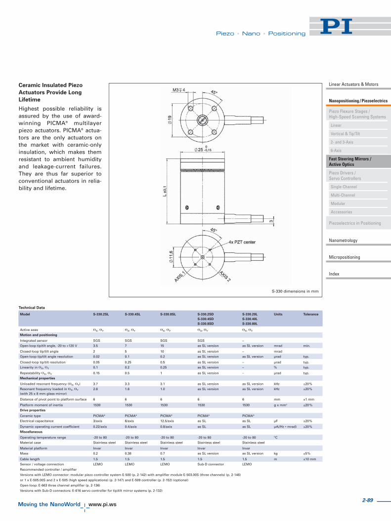
2-89
Piezo • Nano • Positioning
Piezo Flexure Stages /High-Speed Scanning Systems
Nanopositioning / Piezoelectrics
Linear Actuators & Motors
Fast Steering Mirrors /Active Optics
Piezo Drivers /Servo Controllers
Piezoelectrics in Positioning
Nanometrology
Micropositioning
Linear
Vertical & Tip/Tilt
2- and 3-Axis
6-Axis
Single-Channel
Multi-Channel
Modular
Accessories
Index
Technical Data
Model S-330.2SL S-330.4SL S-330.8SL S-330.2SD S-330.20L Units Tolerance
S-330.4SD S-330.40L
S-330.8SD S-330.80L
Active axes �X, �Y �X, �Y �X, �Y �X, �Y �X, �Y
Motion and positioning
Integrated sensor SGS SGS SGS SGS –
Open-loop tip/tilt angle, -20 to +120 V 3.5 7 15 as SL version as SL version mrad min.
Closed-loop tip/tilt angle 2 5 10 as SL version – mrad
Open-loop tip/tilt angle resolution 0.02 0.1 0.2 as SL version as SL version μrad typ.
Closed-loop tip/tilt resolution 0.05 0.25 0.5 as SL version – μrad typ.
Linearity in �X, �Y 0.1 0.2 0.25 as SL version – % typ.
Repeatability �X, �Y 0.15 0.5 1 as SL version – μrad typ.
Mechanical properties
Unloaded resonant frequency (�X, �Y) 3.7 3.3 3.1 as SL version as SL version kHz ±20%
Resonant frequency loaded in �X, �Y 2.6 1.6 1.0 as SL version as SL version kHz ±20%(with 25 x 8 mm glass mirror)
Distance of pivot point to platform surface 6 6 6 6 6 mm ±1 mm
Platform moment of inertia 1530 1530 1530 1530 1530 g x mm2 ±20 %
Drive properties
Ceramic type PICMA® PICMA® PICMA® PICMA® PICMA®
Electrical capacitance 3/axis 6/axis 12.5/axis as SL as SL μF ±20%
Dynamic operating current coefficient 0.22/axis 0.4/axis 0.8/axis as SL as SL μA//Hz • mrad) ±20%
Miscellaneous
Operating temperature range -20 to 80 -20 to 80 -20 to 80 -20 to 80 -20 to 80 °C
Material case Stainless steel Stainless steel Stainless steel Stainless steel Stainless steel
Material platform Invar Invar Invar Invar Invar
Mass 0.2 0.38 0.7 as SL version as SL version kg ±5%
Cable length 1.5 1.5 1.5 1.5 1.5 m ±10 mm
Sensor / voltage connection LEMO LEMO LEMO Sub-D connector LEMO
Recommended controller / amplifier
Versions with LEMO connector: modular piezo controller system E-500 (p. 2-142) with amplifier module E-503.00S (three channels) (p. 2-146)
or 1 x E-505.00S and 2 x E-505 (high speed applications) (p. 2-147) and E-509 controller (p. 2-152) (optional)
Open-loop: E-663 three channel amplifier (p. 2-136)
Versions with Sub-D connectors: E-616 servo controller for tip/tilt mirror systems (p. 2-132)
S-330 dimensions in mm
Ceramic Insulated Piezo
Actuators Provide Long
Lifetime
Highest possible reliability isassured by the use of award-winning PICMA® multilayerpiezo actuators. PICMA® actua-tors are the only actuators onthe market with ceramic-onlyinsulation, which makes themresistant to ambient humidityand leakage-current failures.They are thus far superior toconventional actuators in relia-bility and lifetime.

2-90
©P
hys
ikIn
stru
men
te(P
I)G
mb
H&
Co
.KG
2008
.Su
bje
ctto
chan
ge
wit
ho
ut
no
tice
.All
dat
aar
esu
per
sed
edb
yan
yn
ewre
leas
e.T
he
new
est
rele
ase
for
dat
ash
eets
isav
aila
ble
for
do
wn
load
atw
ww
.pi.w
s.C
at12
0EIn
spir
atio
ns2
009
08/1
0.18
Piezo • Nano • Positioning
S-334 Miniature Piezo Tip/Tilt-Mirror
S-334 Tip/Tilt Mirror System / Scanner ProvidesOptical Deflection Angle up to 120 mrad
Fast Steering Mirror with up to 120 mrad Deflection
S-334 dimensions in mm
� Miniature Design
� Optical Beam Deflection to 120 mrad (~ 6.8°)
� Coplanar Axes & Fixed Pivot Point Eliminate Polarization
Rotation
� Factory Installed Mirror
� Millisecond Response, Resolution to 0.5 μrad
� Closed-loop Position Servo-Control for High Accuracy
� For Mirrors up to 12.5 mm (0.5”) Diameter
� Frictionless, High-Precision Flexure Guiding System
� Parallel Kinematics for Enhanced Dynamics and Better
Multi-Axis Accuracy
S-334 piezo tip/tilt mirrors /scanners provide extremelylarge deflection angles in aminiaturized package. Thesefast steering mirror systemsare based on a sophisticatedparallel-kinematics design with
two coplanar, orthogonal axesand a fixed pivot point.
Large Tip/Tilt Ranges with
Excellent Motion Characteristics
The novel flexure/lever designwith minimized inertia allows
for the exceptionally large tip/tilt range of 60 mrad (50 mradin closed-loop operation, whichis equivalent to 100 mrad opti-cal beam deflection) and veryfast response in the millisecondrange. These parameters makethe system unique in the mar-ket of piezo driven tip/tilt mirrorsystems.
Sub-Microradian Resolution
In addition to the large anglesand the high dynamics theS-334 provides sub-micro-radi-an resolution. The integratedhigh-resolution, full-bridgestrain gauge sensors (SGS)provide absolute position con-trol, excellent repeatability andhigh linearity, typically betterthan 0.25 % over the entire trav-el range.
Differential Drive for Improved
Stability and Dynamics
The S-334 is based on a paral-lel-kinematics design with co-planar axes and a single mov-ing platform. Two pairs of dif-ferentially-driven piezo actua-tors are employed to providethe highest dynamics and posi-tion stability over a wide tem-perature range.
Compared to stacked, (two-stage), piezo or galvo scanners,the single-platform design pro-vides several advantages:smaller package size, identical
dynamic performance in bothaxes, faster response and bet-ter linearity. It also preventspolarization rotation.
High Reliability and Long
Lifetime
The compact S-334 systemsare equipped with preloadedPICMA® high-performance pie-zo actuators which are integrat-ed into a sophisticated, FEA-modeled, flexure guiding sys-tem. The PICMA® actuators fea-ture cofired ceramic encapsula-tion and provide better per-formance and reliability thanconventional piezo actuators.Actuators, guidance and sen-sors are maintenance-free, notsubject to wear and offerextraordinary reliability.
Factory Installed Mirror
The S-334 is equipped with afactory-installed mirror 10 mmin diameter and 2 mm thick(flatness λ/5, reflectivity >98 %from 500 nm to 2 μm).
Ordering Information
S-334.2SD
High-Dynamics Piezo Tip/TiltPlatform, 50 mrad, SGS, Sub-DConnector, incl. Mirror
S-334.2SL
High-Dynamics Piezo Tip/TiltPlatform, 50 mrad, SGS, LEMOConnector, incl. Mirror
Application Examples
� Image processing /stablilization
� Interlacing, dithering
� Laser scanning /beam steering
� Optics
� Optical filters / switches
� Scanning microscopy
� Beam stabilization

2-91
Piezo • Nano • Positioning
Piezo Flexure Stages /High-Speed Scanning Systems
Nanopositioning / Piezoelectrics
Linear Actuators & Motors
Fast Steering Mirrors /Active Optics
Piezo Drivers /Servo Controllers
Piezoelectrics in Positioning
Nanometrology
Micropositioning
Linear
Vertical & Tip/Tilt
2- and 3-Axis
6-Axis
Single-Channel
Multi-Channel
Modular
Accessories
Index
S-334.2SL cable configuration
Resolution of PI piezo tip/tiltplatforms is not limited by fric-tion or stiction. Noise equivalentmotion with E-503 amplifier.(p. 2-146)*Mechanical tilt, optical beamdeflection is 120 mrad (openloop) and 100 mrad (closed-loop), respectively.
Technical Data
Model S-334.2SL S-334.2SD Units Tolerance
Active Axes �X, �Y �X, �Y
Motion and positioning
Integrated sensor SGS SGS
*Open-loop tilt angle at -20 to +120 V 60 60 mrad min. (+20 %/-0 %)
*Closed-loop tilt angle 50 50 mrad
Open-loop resolution 0.5 0.5 μrad typ.
Closed-loop resolution 5 5 μrad typ.
Linearity 0.05 0.05 % typ.
Repeatability 5 5 μrad typ.
Mechanical properties
Resonant frequency under load 1.0 1.0 kHz ±20 %(with standard mirrors)
Resonant frequency with 12.5 mm 0.8 0.8 kHz ±20 %diam. x 2 mm glass mirror
Load capacity 0.2 0.2 N Max.
Distance of pivot point to platform surface 6 6 mm ±1 mm
Platform moment of inertia 1530 1530 g x mm² ±20 %
Standard mirror (mounted) diameter: 10 mm, diameter: 10 mm,thickness: 2 mm, thickness: 2 mm,BK7, λ/5, R > 98 % BK7, λ/5, R > 98 %(λ = 500 nm to 2 μm) (λ = 500 nm to 2 μm)
Drive properties
Ceramic type PICMA® P-885 PICMA® P-885
Electrical capacitance 6 6 μF ±20 %
Miscellaneous
Operating temperature range -20 to 80 -20 to 80 °C
Material casing Titanium Titanium
Mass 0.065 0.065 kg ±5 %
Cable length 2 2 m ±10 mm
Sensor / voltage connection LEMO connector 25-pin sub-D connector
Recommended controller / amplifier Modular piezo controller E-616 controllersystem E-500 (p. 2-144) for tip/tilt mirrorwith amplifier module systems (p. 2-132)E-503.00S (three channels)(p. 2-146) or 1 x E-505.00Sand 2 x E-505 (high speedapplications) (p. 2-147)and E-509 servocontroller (p. 2-152)Open-loop: E-663 threechannel amplifier (p. 2-136)

2-92
©P
hys
ikIn
stru
men
te(P
I)G
mb
H&
Co
.KG
2008
.Su
bje
ctto
chan
ge
wit
ho
ut
no
tice
.All
dat
aar
esu
per
sed
edb
yan
yn
ewre
leas
e.T
he
new
est
rele
ase
for
dat
ash
eets
isav
aila
ble
for
do
wn
load
atw
ww
.pi.w
s.C
at12
0EIn
spir
atio
ns2
009
08/1
0.18
Piezo • Nano • Positioning
S-325 cable configuration (top: S-325.30L, bottom: S-325.3SL)
Application Examples
� Image processing /stablilization
� Optical trapping
� Laser scanning /beam steering
� Laser tuning
� Optical filters / switches
� Optics
� Beam stabilization
High-Speed Tripod System for Mirrors and Optics
S-325 Piezo Z / Tip/Tilt Platform
� Optical Beam Deflection to 10 mrad, Resolution to 50 nrad
� Piston Movement up to 30 μm (for Path Length Adjustment)
� Compact Tripod Design with Coplanar Axes Eliminates
Polarization Rotation
� Sub-Millisecond Responsiveness
� Closed-Loop Versions for Higher Precision
� For Mirrors up to 25 mm (1") Diameter
� Frictionless, High-Precision Flexure Guiding System
� Parallel Kinematics for Enhanced Dynamics and Better Multi-
Axis Accuracy
The S-325 Z/tip/tilt platformsand actuators provide highspeed and precise movementof the platform in two tilt axesas well as sub-nanometer linearresolution with sub-millisecondresponse. The design is based
on a parallel-kinematics direct-drive piezo tripod (see p. 2-83),and they are especially opti-mized for industrial ap-plications where 1.000.000.000motion cycles have to be per-formed without failure or per-
formance degradation. Thesystems are designed for mir-rors and optics up to 25 mm indiameter and can be mountedin any orientation.
The tripod drive offers opti-mum angular stability over awide temperature range. Com-pared to stacked, (two-stage),piezo or galvo scanners, thesingle platform design pro-vides several advantages:smaller package size, identicalsize, identical dynamic per-formance in all axes, fasterresponse and better linearity. Italso prevents polarization rota-tion.
All three piezo linear actuatorscan be driven individually (fortip/tilt movement) or in parallel(for vertical movement) by athree-channel amplifier.
High Resolution, Stability and
Dynamics
The S-325 offers piston move-ment of up to 30 μm (ideal forpath length adjustment) andmechanical tilt up to 5 mrad(equivalent to 10 mrad opticalbeam deflection). The zero-friction piezo drives and flexureguidance allow sub-nanometerlinear resolution and sub-microradian angular resolu-tion.
S-325.30L piezoelectric fast steering mirror platform / scanner
Ordering Information
S-325.3SD
High-Dynamics Piezo Z/Tip/TiltPlatform, 5 mrad, 30 μm, SGS,Sub-D Connector
S-325.3SL
High-Dynamics Piezo Z/Tip/TiltPlatform, 5 mrad, 30 μm, SGS,LEMO Connector
S-325.30L
High-Dynamics Piezo Z/Tip/TiltPlatform, 5 mrad, 30 μm, Open-Loop, LEMO Connector
Open-Loop and Closed-Loop
Operation
In open-loop mode, the plat-form linear motion is roughlyproportional to the appliedvoltage. The S-325.30L open-loop model is ideal for high-bandwidth, high-resolution ap-plications where the absoluteangular position is of second-ary importance (e. g. for track-ing) or where feedback is pro-vided by an external sensor(e. g. CCD, PSD). The S-325.3SLmodel is equipped with high-resolution strain gauge sensorsand provides absolute positioncontrol, high linearity and highrepeatability. The new E-616controller/driver module (seep. 2-132) is ideally suited fortip/tilt OEM applications.

2-93
Piezo • Nano • Positioning
Piezo Flexure Stages /High-Speed Scanning Systems
Nanopositioning / Piezoelectrics
Linear Actuators & Motors
Fast Steering Mirrors /Active Optics
Piezo Drivers /Servo Controllers
Piezoelectrics in Positioning
Nanometrology
Micropositioning
Linear
Vertical & Tip/Tilt
2- and 3-Axis
6-Axis
Single-Channel
Multi-Channel
Modular
Accessories
Index
For maximum tilt range, allthree piezo actuators must bebiased at 50 V. Due to theparallel-kinematics design lineartravel and tilt angle are inter-dependent. The values quotedhere refer to pure linear / pureangular motion. See equations(p. 2-84).Recommended controller /amplifierVersions with LEMO connector:modular piezo controller systemE-500 (p. 2-142) with amplifiermodule E-503.00S (three chan-nels) (p. 2-146) or 1 x E-505.00Sand 2 x E-505 (high speed appli-cations) (p. 2-147) and E-509controller (p. 2-152) (optional)Single-channel (1 per axis):E-610 OEM servo controller /amplifier (p. 2-110), E-625 servocontroller bench-top (p. 2-114)Versions with Sub-D connectors:E-616 servo controller for tip/tiltmirror systems (p. 2-132)
Technical Data
Model S-325.30L S-325.3SL S-325.3SD Units Tolerance
Active axes Z, �X, �Y Z, �X, �Y Z, �X, �Y
Motion and positioning
Integrated sensor – SGS SGSOpen-loop travel, 0 to +100 V 30 30 30 μm min. (+20 %/-0 %)
Open-loop tip/tilt angle, 0 to +100 V 5 5 5 mrad min. (+20 %/-0 %)Closed-loop travel – 30 30 μm
Closed-loop tip/tilt angle – 4 4 mradOpen-loop resolution 0.5 0.5 0.5 nm typ.
Open-loop tip/tilt angle resolution 0.05 0.05 0.05 μrad typ.Closed-loop linear resolution – 0,6 0,6 nm typ.
Closed-loop tip/tilt resolution – 0.1 0.1 μrad typ.Mechanical properties
Unloaded resonant frequency 2 2 2 kHz ±20 %Resonant frequency 1 1 1 kHz ±20 %(with 25 x 8 mm glass mirror)
Distance of pivot point to platform surface 6 6 6 mm ±0.5 mmPlatform moment of inertia 515 515 515 g • mm² ±20 %
Drive properties
Ceramic type PICMA® P-885 PICMA® P-885 PICMA® P-885
Electrical capacitance 9.3 9.3 9.3 μF ±20 %Dynamic operating current coefficient 39 39 39 μA / (Hz • mrad) ±20 %
Miscellaneous
Operating temperature range -20 to 80 -20 to 80 -20 to 80 °C
Material casing Aluminum Aluminum AluminumMass 0.065 0.065 0.065 kg ±5 %
Cable length 2 2 1.5 m ±10 mmSensor / voltage connection LEMO LEMO Sub-D
High Reliability and Long
Lifetime
The compact S-325 systemsare equipped with preloadedPICMA® high-performance pie-zo actuators which are integrat-ed into a sophisticated, FEA-modeled, flexure guiding sys-tem. The PICMA® actuators fea-ture cofired ceramic encapsula-tion and provide better per-formance and reliability thanconventional piezo actuators.Actuators, guidance and sen-sors are maintenance-free, notsubject to wear and offer extra-ordinary reliability.
S-325 dimensions in mm

©P
hys
ikIn
stru
men
te(P
I)G
mb
H&
Co
.KG
2008
.Su
bje
ctto
chan
ge
wit
ho
ut
no
tice
.All
dat
aar
esu
per
sed
edb
yan
yn
ewre
leas
e.T
he
new
est
rele
ase
for
dat
ash
eets
isav
aila
ble
for
do
wn
load
atw
ww
.pi.w
s.C
at12
0EIn
spir
atio
ns2
009
08/1
0.18
Piezo • Nano • Positioning
Application Examples
� Image processing /stablilization
� Interferometry
� Laser scanning /beam steering
� Laser tuning
� Optical filters / switches
� Beam stabilization
High-Speed System with Clear Aperture
S-310 – S-316 Piezo Z/Tip/Tilt Scanner
S-310.10, S-316.10piezo systems for scanning,
optics alignment and mirror shifter alignment
S-310 to S-316 multi-axis tip/tiltplatforms and Z-positioners arefast, compact units based on apiezo tripod design. They offerpiston movement up to 12 μmand tilt movement up to1.2 mrad (2.4 mrad opticalbeam deflection) with sub-mil-lisecond response and settling.
The tripod design featuresoptimum angular stability overa wide temperature range.
The systems are designedfor mirrors and optics up to25 mm in diameter and can bemounted in any orientation;the clear aperture is ideal fortransmitted-light applications(e. g. for optical filters).
Open-Loop and Closed-Loop
Operation
In open-loop mode, the tip/tiltangle is roughly proportionalto the applied voltage. TheS-310 to S-315 open-loop mod-els are ideal for high-speed,high resolution applicationswhere the absolute angularposition is of secondary impor-tance (e. g. for tracking) or
where feedback is provided byan external sensor (e. g. CCD,PSD). The S-316.10 model isequipped with high-resolutionstrain gauge sensors and pro-vides absolute position con-trol, high linearity and highrepeatability.
Available Versions
� S-310.10, S-314.10
Open-loop Z-platforms; allthree piezo linear actuators areelectrically connected in paral-lel, providing vertical position-ing (piston movement) of thetop ring. Only one drive chan-nel is required.
� S-311.10, S-315.10
Open-loop Z/tip/tilt position-ers; all three piezo linear actua-tors can be driven individually(or in parallel) by a three-chan-nel amplifier. Vertical (pistonmovement) positioning andtip/tilt positioning are possible.
� S-316.10
Closed-loop Z/tip/tilt position-er. All three piezo linear actua-tors are equipped with straingauge position feedback sen-sors and can be driven individ-ually (or in parallel) by a three-
� 10 mm Clear Aperture
� Piezo Tripod Design
� Optical Beam Deflection to 2,4 mrad
� Piston Movement up to 12 μm (phase shifter)
� Sub-Millisecond Response, Sub-Microradian Resolution
� Closed-Loop Versions for Higher Precision
� For Optics, Mirrors or Other Components
� Frictionless, High-Precision Flexure Guiding System
� Parallel Kinematics for Enhanced Dynamics and Better Multi-
Axis Accuracy
S-316 cable configuration
channel amplifier with a posi-tion servo-controller. Verticalpositioning (piston movement)and tip/tilt positioning are pos-sible. The integrated positionfeedback sensors provide sub-microradian resolution andhigh repeatability.
S-315 cable configuration
Ordering Information
S-310.10
Piezo Actuator, Clear Aperture,6 μm, LEMO Connector
S-311.10
Piezo Z/Tip/Tilt Platform,Clear Aperture, 600 μrad, 6 μm,LEMO Connector
S-314.10
Piezo Actuator, Clear Aperture,12 μm, LEMO Connector
S-315.10
Piezo Z/Tip/Tilt Platform,Clear Aperture, 1.2 mrad, 12 μm,LEMO Connector
S-316.10
Piezo Z/Tip/Tilt Platform,Clear Aperture, 1.2 mrad, 12 μm,SGS, LEMO Connector
S-316.10
Piezo Z/Tip/Tilt Platform,Clear Aperture, 1.2 mrad, 12 μm,SGS, Sub-D Connector
2-94

Piezo • Nano • Positioning
Piezo Flexure Stages /High-Speed Scanning Systems
Nanopositioning / Piezoelectrics
Linear Actuators & Motors
Fast Steering Mirrors /Active Optics
Piezo Drivers /Servo Controllers
Piezoelectrics in Positioning
Nanometrology
Micropositioning
Linear
Vertical & Tip/Tilt
2- and 3-Axis
6-Axis
Single-Channel
Multi-Channel
Modular
Accessories
Index
Resolution of PI piezo tip/tiltplatforms is not limited by fric-tion or stiction. Noise equivalentmotion with E-503 amplifier(p. 2-146).
*Mechanical tilt, optical beamdeflection is twice as large. Formaximum tilt range, all threepiezo actuators must be biasedat 50 V. Due to the parallel-kinematics design linear traveland tilt angle are interdepen-dent. The values quoted hererefer to pure linear / pure angu-lar motion (equations p. 2-84).
Recommended controller /amplifierSingle-channel (1 per axis):E-610 servo-controller / amplifier(p. 2-110), E-625 servo-control-ler, bench-top (p. 2-114)
Multi-channel: modular piezocontroller system E-500 (p. 2-142)with amplifier moduleE-503 (three channels) (p. 2-146)or E-505 (1 per axis, high-power)(p. 2-147) and E-509 controller(p. 2-152) (optional), E-517 inter-face module (p. 2-156) (optional)
S-310 – S-316 dimensions (in mm)
High Reliability and Long
Lifetime
The compact S-310 - S-316 sys-tems are equipped with pre-loaded PICMA® high-perform-ance piezo actuators which areintegrated into a sophisticated,FEA-modeled, flexure guidingsystem. The PICMA® actuatorsfeature cofired ceramic encap-sulation and provide betterperformance and reliabilitythan conventional piezo actua-tors. Actuators, guidance andsensors are maintenance-free,not subject to wear and offerextraordinary reliability.
Technical Data
Model S-310.10 S-314.10 S-311.10 S-315.10 S-316.10 Units Tolerance
Active axes Z Z Z, �X, �Y Z, �X, �Y Z, �X, �Y
Motion and positioning
Integrated sensor – – – – SGSOpen-loop travel, 0 to +100 V 6 / – 12 / – 6 / – 12 / – 12 / 12 μm min. (+20 %/-0 %)*Open-loop tilt angle @ 0 to 100 V – – 600 1200 1200 μrad min. (+20 %/-0 %)Closed-loop travel – – – – 12 μm*Closed-loop tilt angle – – – – 1200 mradOpen-loop resolution 0.1 0.2 0.1 0.2 0.2 nm typ.Open-loop tip/tilt angle resolution 0.02 0.05 0.05 μrad typ.Closed-loop resolution – – – – 0.4 nm typ.Closed-loop tip/tilt resolution – – – – 0.1 μrad typ.Linearity – – – – 0.2 % typ.Mechanical properties
Stiffness 20 10 20 10 10 N/μm ±20 %Unloaded resonant frequency (Z) 9.5 5.5 9.5 5.5 5.5 kHz ±20 %Resonant frequency 6.5 4.4 6.5 4.1 4.1 kHz ±20 %(with 15 x 4 mm glass mirror)Resonant frequency 6.1 4.2 6.1 3.4 3.4 kHz ±20 %(with 20 x 4 mm glass mirror)
Distance of pivot point – – 5 5 5 mm ±1 mmto platform surface
Platform moment of inertia – – 150 150 150 g • mm² ±20 %Drive properties
Ceramic type PICMA® PICMA® PICMA® PICMA® PICMA®
P-882 P-882 P-882 P-882 P-882
Electrical capacitance 0.39 0.93 0.39 0.93 0.93 μF ±20 %Dynamic operating current coefficient 8 10 8 10 10 μA / (Hz • mrad) ±20 %Miscellaneous
Operating temperature range -20 to 80 -20 to 80 -20 to 80 -20 to 80 -20 to 80 °CMaterial Stainless Stainless Stainless Stainless Stainless
steel steel steel steel steel
Mass 0.45 0.55 0.45 0.55 0.55 kg ±5%Cable length 2 2 2 2 2 m ±10 mmSensor connection – – – – LEMOVoltage connection LEMO LEMO LEMO LEMO LEMO
2-95

Piezo • Nano • Positioning
S-323 Piezo Z/Tip/Tilt PlatformHigh Dynamics & Stability Nanopositioning System with Direct Metrology
� Optical Beam Deflection to 6 mrad
� Sub-μrad Resolution for High Positioning Stability
� Position Servo-Control with Capacitive Sensors
� Frictionless, High-Precision Flexure Guiding System
� System Combination with Digital Controllers for Highest
Linearity
S-303 Piezo Phase ShifterHighest Dynamics and Stability with Capacitive Feedback Sensor
� 25 kHz Resonant Frequency for Sub-Millisecond Dynamics
� Capacitive Sensor Option for Highest Linearity and Stability
� 3 μm Travel Range
� Compact Size: 30 mm Diameter x 10 mm
� Aperture with Open-Loop Versions
� Invar Option for Highest Thermal Stability
S-224 -S-226 Piezo Tilt-MirrorFast Steering Mirror Combines Highest Dynamics and Compact Design
� Optical Beam Deflection to 4.4 mrad
� Sub-μrad Resolution, Sub-Millisecond Response
� Frictionless, High-Precision Flexure Guiding System
� Includes BK7 Mirror
� Optional Position Feedback Sensor
� Outstanding Lifetime Due to PICMA® Piezo Actuators
The S-323 Z/tip/tilt platform integrates capacitivesensors for highest resolution and stability
S-303 closed-loop model (left) and open-loopmodel (right). DIP switch for size comparison
S-224 Piezo tip/tilt mirror for high-speed beamsteering tasks and image stabilization applications
Model Active Travel range Resolution Unloaded resonant
axes frequency
S-323.3CD Z, θX, θY 30 μm, ±1.5 mrad 0.1 nm, ±0.05 μrad 1.7 kHz
Model Active Closed-loop/ Closed-loop/ Unloaded
axes open-loop travel open-loop resonant
@ -20 to +120V resolution frequency
S-303.CD (closed-loop)/ Z 2 / 3 μm 0.03 nm 25 kHzS-302.0L (open-loop)
Model Active Open-loop tilt Closed-loop/ Unloaded
axes angle @ 0 to +100V open-loop resonant
resolution frequency
S-224.00 (open-loop)/ θX 2.0 / 2.2 mrad 0.05 / 0.1 μrad 9 kHzS-226.00 (closed-loop)
2-96
©P
hys
ikIn
stru
men
te(P
I)G
mb
H&
Co
.KG
2008
.Su
bje
ctto
chan
ge
wit
ho
ut
no
tice
.All
dat
aar
esu
per
sed
edb
yan
yn
ewre
leas
e.T
he
new
est
rele
ase
for
dat
ash
eets
isav
aila
ble
for
do
wn
load
atw
ww
.pi.w
s.C
at12
0EIn
spir
atio
ns2
009
08/1
0.18

2-97
Piezo • Nano • Positioning
Piezo Flexure Stages /High-Speed Scanning Systems
Nanopositioning / Piezoelectrics
Linear Actuators & Motors
Fast Steering Mirrors /Active Optics
Piezo Drivers /Servo Controllers
Piezoelectrics in Positioning
Nanometrology
Micropositioning
Linear
Vertical & Tip/Tilt
2- and 3-Axis
6-Axis
Single-Channel
Multi-Channel
Modular
Accessories
Index
Details on Specifications for Active Optics / Steering MirrorsMotion and Positioning
Performance specifications arevalid for room temperature(22° ±3 °C) and closed-loopsystems are calibrated at thistemperature (specifications forother operating temperatures onrequest). Recalibration is recom-mended for operation at a signif-icantly higher or lower tempera-ture. Custom designs for ultra-low or ultra-high temperatureson request.
Integrated feedback sensor
Absolute measuring capacitiveand strain gauge (SGS) sensorsare used to provide positioninformation to the controller. Fordetails see the tutorial “Piezo-electrics in Positioning” section(see p. 2-187).
Open-loop linear travel
@ 0 to 100 V
Typical open-loop travel at 0 to100 V operating voltage. Max.recommended operating voltagerange is -20 to +120 V (extremesfor short durations only).
Closed-loop linear travel
Travel provided in closed-loopoperation. PI piezo amplifiers
have an output voltage range of-20 to +120 V or -30 to +135 V toprovide enough margin for theservo-controller to compensatefor load changes, etc.
Open-Loop Tilt Angle
@ 0 to 100 V
Typical open-loop tilt angle at 0to 100 V operating voltage. Fordifferential-drive tilt platforms,0° is reached at 50 V drive volt-age, the maximum negativeangle at 0 V and the maximumpositive angle at 100 V. Max.operating voltage range is -20 to+120 V (outside 0 to 100 V forshort durations only).
Closed-Loop Travel
Tilt provided in closed-loop oper-ation at room temperature. PIpiezo amplifiers have an outputvoltage range of -20 to +120 V or-30 to 135 V to provide enoughmargin for the controller to com-pensate for load changes etc.
Open-loop /
closed-loop resolution
Resolution of piezo flexurestages is basically infinitesimalbecause it is not limited by stic-
tion or friction. Instead of resolu-tion, the noise-equivalent mo-tion is specified. Values are typi-cal results (RMS, 1 σ), measuredwith E-503 amplifier module inE-500/501 chassis.
Full-range repeatability (typ.)
Typical values in closed-loopmode (RMS, 1 σ). Repeatabilityis a percentage of the total dis-tance or angle traveled. Forsmall ranges, repeatability issignificantly better.
Pitch / Yaw / Roll / Rotational
Runout
Typical rotational off-axis error;sometimes associated with aparticular motion axis, as in“Rotational runout (Z motion)”.
Straightness / Flatness /
Crosstalk
Typical linear off-axis error;sometimes associated with aparticular motion axis, as in“Crosstalk (Z motion)”.
Mechanical Properties
Stiffness
Static large-signal stiffness ofthe piezo mechanics in operatingdirection at room temperature.Small-signal stiffness and dyna-mic stiffness may differ becauseof effects caused by the activenature of piezoelectric material,compound effects, etc. For de-tails see the tutorial “Piezoelec-trics in Positioning” section (seep. 2-189 ff ).
Unloaded resonant frequency
Lowest tilt resonant frequencyaround active axis without mir-ror attached to platform (doesnot specify the maximum oper-ating frequency). For details seethe tutorial “Piezoelectrics inPositioning” Section (see p.2-192 ff ).
Resonant frequency with
mirror
Example of how a load (mirror)attached to the platform affectsthe resonant frequency (calculat-ed data). See “Dynamic Behav-ior” (p. 2-84) for further details.

2-98
©P
hys
ikIn
stru
men
te(P
I)G
mb
H&
Co
.KG
2008
.Su
bje
ctto
chan
ge
wit
ho
ut
no
tice
.C
at12
0EIn
spir
atio
ns2
009
08/1
0.18
Piezo • Nano • Positioning
Drive Properties
Electrical capacitance
The piezo capacitance values in-dicated in the technical datatables are small-signal values(measured at 1 V, 1000 Hz, 20 °C,no load). Large-signal values atroom temperature are 30 to 50 %higher. The capacitance of piezoceramics changes with ampli-tude, temperature, and load, upto 200 % of the unloaded, small-signal capacitance at room tem-perature. For detailed informa-
tion on power requirements,refer to the amplifier frequency-response graphs in the “PiezoDrivers / Servo Controllers” (seep. 2-99 ff ) section of this catalog.
Dynamic Operating Current
Coefficient (DOCC)
Average electrical current (sup-plied by the amplifier) requiredto drive a piezo actuator per unitfrequency and unit displacement(sine-wave operation). For exam-
ple, to find out if a selectedamplifier can drive a given piezotilt platform at 50 Hz with300 μrad amplitude, multiply theDOC coefficient by 50 and 300and check if the result is lessthan or equal to the output cur-rent of the selected amplifier. Fordetails see the tutorial “Piezo-electrics in Positioning” (see p.2-195 ff ) section.
Miscellaneous
Operating temperature range
Typically -20 to +80 °C, the tem-perature range indicates wherethe piezo stage may be operatedwithout damage. Performancespecifications are valid for roomtemperature (22 °C) and closed-loop systems are calibrated foroptimum performance at thistemperature (specifications forother operating temperatures onrequest). Recalibration is recom-mended for operation at a signif-icantly higher or lower tempera-ture. Custom designs for ultra-low or ultra-high temperatureson request.
Material
Flexure stages are usually madeof anodized aluminum or stain-less steel. Small amounts ofother materials may be usedinternally (for spring preload,piezo coupling, mounting, ther-mal compensation, etc.).
Al: Aluminum
N-S: Non-magnetic stainlesssteel
S: Ferromagnetic stainlesssteel
I: Invar
T: Titanium
Voltage connection
Standard operating voltage con-nectors are LEMO and sub-Dtype connectors.
LEMO connector: LEMO FFA.00.250, male. Cable: coaxial, RG178, Teflon coated, 1 m
Sensor connection
Standard sensor connectors areLEMO and sub-D type connec-tors.
Sub-D special connectors con-tain both piezo voltage and sen-sor connections.
For extension cables and adap-ters, see “Accessories” (p.2-168 ff ), in the “Piezo Drivers /Servo Controllers” Section.

Piezo • Nano • Positioning
Piezoelectrics in Positioning
Nanopositioning / Piezoelectrics

2-172
©P
hys
ikIn
stru
men
te(P
I)G
mb
H&
Co
.KG
2008
.Su
bje
ctto
chan
ge
wit
ho
ut
no
tice
.C
at12
0EIn
spir
atio
ns2
009
08/1
0.18
Piezo • Nano • Positioning
Contents . . . . . . . . . . . . . . . . . . . . . . . . . . . . . . . . . . . . . . . . . . . . . . . . . . . . . . . . . . . . 2-172
Features and Applications of Piezoelectric Positioning Systems . . . . . . . . . . . . . . 2-174
Glossary . . . . . . . . . . . . . . . . . . . . . . . . . . . . . . . . . . . . . . . . . . . . . . . . . . . . . . . . . . . . 2-175
Introduction . . . . . . . . . . . . . . . . . . . . . . . . . . . . . . . . . . . . . . . . . . . . . . . . . . . . . . . . . 2-177
Nanopositioning with Piezoelectric Technology . . . . . . . . . . . . . . . . . . . . . . . . . . . . 2-177Features of Piezoelectric Actuators . . . . . . . . . . . . . . . . . . . . . . . . . . . . . . . . . . . . . . 2-177
Quick Facts . . . . . . . . . . . . . . . . . . . . . . . . . . . . . . . . . . . . . . . . . . . . . . . . . . . . . . . . . . 2-178
Actuator Designs . . . . . . . . . . . . . . . . . . . . . . . . . . . . . . . . . . . . . . . . . . . . . . . . . . . . . 2-178Operating Characteristics of Piezoelectric Actuators . . . . . . . . . . . . . . . . . . . . . . . . 2-179
Fundamentals of Piezoelectricity . . . . . . . . . . . . . . . . . . . . . . . . . . . . . . . . . . . . . . . . 2-181
Material Properties . . . . . . . . . . . . . . . . . . . . . . . . . . . . . . . . . . . . . . . . . . . . . . . . . . . 2-181PZT Ceramics Manufacturing Process . . . . . . . . . . . . . . . . . . . . . . . . . . . . . . . . . . . . 2-182Definition of Piezoelectric Coefficients and Directions . . . . . . . . . . . . . . . . . . . . . . . 2-182Resolution . . . . . . . . . . . . . . . . . . . . . . . . . . . . . . . . . . . . . . . . . . . . . . . . . . . . . . . . . . . 2-183
Fundamentals of Piezomechanics . . . . . . . . . . . . . . . . . . . . . . . . . . . . . . . . . . . . . . . 2-184
Displacement of Piezo Actuators (Stack & Contraction Type) . . . . . . . . . . . . . . . . . 2-184Hysteresis (Open-Loop Piezo Operation) . . . . . . . . . . . . . . . . . . . . . . . . . . . . . . . . . . 2-185Creep / Drift (Open-Loop Piezo Operation) . . . . . . . . . . . . . . . . . . . . . . . . . . . . . . . . 2-186Aging . . . . . . . . . . . . . . . . . . . . . . . . . . . . . . . . . . . . . . . . . . . . . . . . . . . . . . . . . . . . . . . 2-186
Actuators and Sensors . . . . . . . . . . . . . . . . . . . . . . . . . . . . . . . . . . . . . . . . . . . . . . . . 2-187
Metrology for Nanopositioning Systems . . . . . . . . . . . . . . . . . . . . . . . . . . . . . . . . . 2-187Indirect (Inferred) Metrology . . . . . . . . . . . . . . . . . . . . . . . . . . . . . . . . . . . . . . . . . . . . 2-187Direct Metrology . . . . . . . . . . . . . . . . . . . . . . . . . . . . . . . . . . . . . . . . . . . . . . . . . . . . . 2-187Parallel and Serial Metrology . . . . . . . . . . . . . . . . . . . . . . . . . . . . . . . . . . . . . . . . . . . 2-187High-Resolution Sensors—Strain Gauge Sensors . . . . . . . . . . . . . . . . . . . . . . . . . . 2-187Linear Variable Differential Transformers (LVDTs) . . . . . . . . . . . . . . . . . . . . . . . . . . 2-188Capacitive Position Sensors . . . . . . . . . . . . . . . . . . . . . . . . . . . . . . . . . . . . . . . . . . . 2-188
Fundamentals of Piezoelectric Actuators . . . . . . . . . . . . . . . . . . . . . . . . . . . . . . . . . 2-189
Forces and Stiffness . . . . . . . . . . . . . . . . . . . . . . . . . . . . . . . . . . . . . . . . . . . . . . . . . . 2-189Maximum Applicable Forces (Compressive Load Limit, Tensile Load Limit) . . . . 2-189Stiffness . . . . . . . . . . . . . . . . . . . . . . . . . . . . . . . . . . . . . . . . . . . . . . . . . . . . . . . . . . . . 2-189Force Generation . . . . . . . . . . . . . . . . . . . . . . . . . . . . . . . . . . . . . . . . . . . . . . . . . . . . . 2-190Displacement and External Forces . . . . . . . . . . . . . . . . . . . . . . . . . . . . . . . . . . . . . . . 2-191
Dynamic Operation Fundamentals . . . . . . . . . . . . . . . . . . . . . . . . . . . . . . . . . . . . . . 2-192
Dynamic Forces . . . . . . . . . . . . . . . . . . . . . . . . . . . . . . . . . . . . . . . . . . . . . . . . . . . . . . 2-192Resonant Frequency . . . . . . . . . . . . . . . . . . . . . . . . . . . . . . . . . . . . . . . . . . . . . . . . . . 2-193How Fast Can a Piezo Actuator Expand? . . . . . . . . . . . . . . . . . . . . . . . . . . . . . . . . . . 2-194
ContentsPiezoelectrics in Positioning

2-173
Piezo • Nano • Positioning
Piezo Flexure Stages /High-Speed Scanning Systems
Nanopositioning / Piezoelectrics
Linear Actuators & Motors
Fast Steering Mirrors /Active Optics
Piezo Drivers /Servo Controllers
Piezoelectrics in Positioning
Nanometrology
Micropositioning
Linear
Vertical & Tip/Tilt
2- and 3-Axis
6-Axis
Single-Channel
Multi-Channel
Modular
Accessories
Index
Piezo Actuator Electrical Fundamentals . . . . . . . . . . . . . . . . . . . . . . . . . . . . . . . . . . 2-195
Electrical Requirements for Piezo Operation . . . . . . . . . . . . . . . . . . . . . . . . . . . . . . . 2-195Static Operation . . . . . . . . . . . . . . . . . . . . . . . . . . . . . . . . . . . . . . . . . . . . . . . . . . . . . . 2-195Dynamic Operation (Linear) . . . . . . . . . . . . . . . . . . . . . . . . . . . . . . . . . . . . . . . . . . . . 2-196Dynamic Operating Current Coefficient (DOCC) . . . . . . . . . . . . . . . . . . . . . . . . . . . . 2-197Dynamic Operation (Switched) . . . . . . . . . . . . . . . . . . . . . . . . . . . . . . . . . . . . . . . . . . 2-197Heat Generation in a Piezo Actuator in Dynamic Operation . . . . . . . . . . . . . . . . . . 2-198
Control of Piezo Actuators and Stages . . . . . . . . . . . . . . . . . . . . . . . . . . . . . . . . . . . 2-199
Position Servo-Control . . . . . . . . . . . . . . . . . . . . . . . . . . . . . . . . . . . . . . . . . . . . . . . . 2-199Open- and Closed-Loop Resolution . . . . . . . . . . . . . . . . . . . . . . . . . . . . . . . . . . . . . . 2-200Piezo Metrology Protocol . . . . . . . . . . . . . . . . . . . . . . . . . . . . . . . . . . . . . . . . . . . . . . 2-200Methods to Improve Piezo Dynamics . . . . . . . . . . . . . . . . . . . . . . . . . . . . . . . . . . . . 2-201InputShaping® . . . . . . . . . . . . . . . . . . . . . . . . . . . . . . . . . . . . . . . . . . . . . . . . . . . . . . . 2-201Signal Preshaping / Dynamic Digital Linearization (DDL) . . . . . . . . . . . . . . . . . . . . 2-202Dynamic Digital Linearization (DDL) . . . . . . . . . . . . . . . . . . . . . . . . . . . . . . . . . . . . . 2-203
Environmental Conditions and Influences . . . . . . . . . . . . . . . . . . . . . . . . . . . . . . . . 2-204
Temperature Effects . . . . . . . . . . . . . . . . . . . . . . . . . . . . . . . . . . . . . . . . . . . . . . . . . . . 2-204Linear Thermal Expansion . . . . . . . . . . . . . . . . . . . . . . . . . . . . . . . . . . . . . . . . . . . . . 2-204Temperature Dependency of the Piezo Effect . . . . . . . . . . . . . . . . . . . . . . . . . . . . . . 2-204Piezo Operation in High Humidity . . . . . . . . . . . . . . . . . . . . . . . . . . . . . . . . . . . . . . . 2-204Piezo Operation in Inert Gas Atmospheres . . . . . . . . . . . . . . . . . . . . . . . . . . . . . . . . 2-205Vacuum Operation of Piezo Actuators . . . . . . . . . . . . . . . . . . . . . . . . . . . . . . . . . . . . 2-205Lifetime of Piezo Actuators . . . . . . . . . . . . . . . . . . . . . . . . . . . . . . . . . . . . . . . . . . . . . 2-206
Basic Designs of Piezoelectric Positioning Drives/Systems . . . . . . . . . . . . . . . . . . 2-207
Stack Design (Translators) . . . . . . . . . . . . . . . . . . . . . . . . . . . . . . . . . . . . . . . . . . . . . 2-207Laminar Design (Contraction-Type Actuators) . . . . . . . . . . . . . . . . . . . . . . . . . . . . . 2-207Tube Design . . . . . . . . . . . . . . . . . . . . . . . . . . . . . . . . . . . . . . . . . . . . . . . . . . . . . . . . . 2-208Bender Type Actuators (Bimorph and Multimorph Design) . . . . . . . . . . . . . . . . . . 2-209Shear Actuators . . . . . . . . . . . . . . . . . . . . . . . . . . . . . . . . . . . . . . . . . . . . . . . . . . . . . . 2-209Piezo Actuators with Integrated Lever Motion Amplifiers . . . . . . . . . . . . . . . . . . . . 2-210Piezo Flexure Nanopositioners . . . . . . . . . . . . . . . . . . . . . . . . . . . . . . . . . . . . . . . . . . 2-211
Parallel and Serial Kinematics / Metrology . . . . . . . . . . . . . . . . . . . . . . . . . . . . . . . 2-212
Direct and Indirect Metrology . . . . . . . . . . . . . . . . . . . . . . . . . . . . . . . . . . . . . . . . . . 2-212Parallel and Serial Kinematics . . . . . . . . . . . . . . . . . . . . . . . . . . . . . . . . . . . . . . . . . . 2-213
PMN Compared to PZT . . . . . . . . . . . . . . . . . . . . . . . . . . . . . . . . . . . . . . . . . . . . . . . . 2-214
Electrostrictive Actuators (PMN) . . . . . . . . . . . . . . . . . . . . . . . . . . . . . . . . . . . . . . . . 2-214
Summary . . . . . . . . . . . . . . . . . . . . . . . . . . . . . . . . . . . . . . . . . . . . . . . . . . . . . . . . . . . 2-215
Mounting and Handling Guidelines for Piezo Translators . . . . . . . . . . . . . . . . . . . 2-216
Symbols and Units . . . . . . . . . . . . . . . . . . . . . . . . . . . . . . . . . . . . . . . . . . . . . . . . . . . 2-217

2-174
©P
hys
ikIn
stru
men
te(P
I)G
mb
H&
Co
.KG
2008
.Su
bje
ctto
chan
ge
wit
ho
ut
no
tice
.C
at12
0EIn
spir
atio
ns2
009
08/1
0.18
Piezo • Nano • Positioning
Data Storage
� MR head testing� Spin stands� Disk testing� Active vibration cancellation� Pole-tip recession test
Semiconductors, Microelectronics
� Nano & Microlithography� Nanometrologie� Wafer and mask positioning� Critical-dimension-test� Inspection systems� Active vibration cancellation
Precision Mechanics
� Fast tool servos� Non-circular grinding,
drilling, turning� Active vibration cancellation� Structural deformation� Tool adjustment
� Wear compensation� Needle-valve actuation� Micropumps� Linear drives� Knife edge control in extrusion
tools� Micro engraving systems� Shock wave generation
Life Science, Medical Technology
� Scanning microscopy� Patch clamp� Nanoliter pumps� Gene manipulation� Micromanipulation� Cell penetration� Microdispensers
Optics, Photonics,
Nanometrologie
� Scanning mirrors� Image stabilization,
pixel multiplication
� Scanning microscopy� Auto focus systems� Interferometry� Fiber optic alignment� Fiber optics switching� Adaptive and active optics� Laser tuning� Stimulation of vibrations
Applications for Piezo Positioning Technology
Features of Piezoelectric Positioning Systems
Unlimited Resolution
Piezoelectric actuators convertelectrical energy directly to me-chanical energy. They make mo-tion in the sub-nanometer rangepossible. There are no movingparts in contact with each other tolimit resolution.
Fast Expansion
Piezo actuators react in a matter ofmicroseconds. Acceleration ratesof more than 10,000 g can be ob-tained.
High Force Generation
High-load piezo actuators capableof moving loads of several tons areavailable today. They can covertravel ranges of several 100 μmwith resolutions in the sub-na-nometer range (see examples likethe P-056, in the “Piezo Actuators& Components” section).
No Magnetic Fields
The piezoelectric effect is related toelectric fields. Piezo actuators donot produce magnetic fields nor
are they affected by them. Piezodevices are especially well suitedfor applications where magneticfields cannot be tolerated.
Low Power Consumption
Static operation, even holdingheavy loads for long periods, con-sumes virtually no power. A piezoactuator behaves very much like anelectrical capacitor. When at rest,no heat is generated.
No Wear and Tear
A piezo actuator has no movingparts like gears or bearings. Its dis-placement is based on solid statedynamics and shows no wear andtear. PI has conducted endurancetests on piezo actuators in whichno measurable change in perform-ance was observed after severalbillion cycles.
Vacuum and Clean Room
Compatible
Piezoelectric actuators neithercause wear nor require lubricants.The new PICMA® actuators with
ceramic insulation have no poly-mer coating and are thus ideal forUHV (ultra-high vacuum) applica-tions.
Operation at Cryogenic
Temperatures
The piezoelectric effect continuesto operate even at temperaturesclose to 0 kelvin. PI offers speciallyprepared actuators for use at cryo-genic temperatures.
Selection of piezo nanopositioning stages
Piezoelectric nanopositioning systems large(e.g. for precision machining), medium (e.g. forinterferometry), small (e.g. for data storagemedium testing)
Properties / Applications

2-175
Piezo • Nano • Positioning
Piezo Flexure Stages /High-Speed Scanning Systems
Nanopositioning / Piezoelectrics
Linear Actuators & Motors
Fast Steering Mirrors /Active Optics
Piezo Drivers /Servo Controllers
Piezoelectrics in Positioning
Nanometrology
Micropositioning
Linear
Vertical & Tip/Tilt
2- and 3-Axis
6-Axis
Single-Channel
Multi-Channel
Modular
Accessories
Index
Nanopositioning system featuring parallelkinematics and parallel metrology.
Piezoceramic layers in a monolithicactuator (LVPZT).
Equipment for fully automated screen printing of electrodes on piezoelectric and dielectric ceramics.
Glossary
Piezoceramic layers in a “classical”stack actuator (HVPZT).
See also the MicropositioningFundamentals Glossary (p. 4-128).
Actuator:
A device that can produce force ormotion (displacement).
Blocked Force:
The maximum force an actuatorcan generate if blocked by an infi-nitely rigid restraint.
Ceramic:
A polycrystalline, inorganic mate-rial.
Closed-Loop Operation:
The displacement of the actuatoris corrected by a servo-controllercompensating for nonlinearity,hysteresis and creep. See also“Open-Loop Operation“.
Compliance:
Displacement produced per unitforce. The reciprocal of stiffness.
Creep:
An unwanted change in the dis-placement over time.
Curie Temperature:
The temperature at which thecrystalline structure changes froma piezoelectric (non-symmetrical)
to a non-piezoelectric (symmetri-cal) form. At this temperature PZTceramics looses the piezoelectricproperties.
Drift:
See “creep”
Domain:
A region of electric dipoles withsimilar orientation.
HVPZT:
Acronym for High-Voltage PZT(actuator).
Hysteresis:
Hysteresis in piezo actuators isbased on crystalline polarizationand molecular effects and occurswhen reversing driving direction.Hysteresis is not to be confusedwith backlash.
LVPZT:
Acronym for low-voltage PZT(actuator).
Monolithic Multilayer Actuator:
An actuator manufactured in afashion similar to multilayer ce-ramic capacitors. Ceramic andelectrode material are cofired inone step. Layer thickness is typi-cally on the order of 20 to 100 μm.
Open-Loop Operation:
The actuator is used without aposition sensor. Displacementroughly corresponds to the drivevoltage. Creep, nonlinearity andhysteresis remain uncompensat-ed.
Parallel Kinematics:
Unlike in serial kinematics de-signs, all actuators act upon thesame moving platform. Advan-tages: Minimized inertia, nomoving cables, lower center of
gravity, no cumulative guidingerrors and more-compact con-struction.

2-176
©P
hys
ikIn
stru
men
te(P
I)G
mb
H&
Co
.KG
2008
.Su
bje
ctto
chan
ge
wit
ho
ut
no
tice
.C
at12
0EIn
spir
atio
ns2
009
08/1
0.18
Piezo • Nano • Positioning
Design principle of a stacked XY piezo stage(serial kinematics).
Parallel Metrology:
Unlike in serial metrology designs,each sensor measures the positionof the same moving platform in therespective degree of freedom. Thiskeeps the off-axis runout of allactuators inside the servo-controlloop and allows it to be correctedautomatically (active guidance).
Piezoelectric Materials:
Materials that change their dimen-sions when a voltage is appliedand produce a charge when pres-sure is applied.
Poling / Polarization:
The procedure by which the bulkmaterial is made to take on piezo-electric properties, i.e. the electricalalignment of the unit cells in a pie-zoelectric material.
PZT:
Acronym for plumbum (lead) zir-conate titanate. Polycrystalline ce-ramic material with piezoelectricproperties. Often also used to referto a piezo actuator or translator.
Serial Kinematics:
Unlike in parallel kinematics de-signs, each actuator acts upon aseparate platform of its own. Thereis a clear relationship betweenactuators and axes.Advantages: Simpler to assemble;simpler control algorithm.Disadvantages: Poorer dynamiccharacteristics, integrated “Parallel
Metrology” is not possible, cumu-lative guiding errors, lower accura-cy.
Serial Metrology:
One sensor is assigned to eachdegree of freedom to be servo-con-trolled. Undesired off-axis motion(guiding error) from other axes inthe direction of a given sensor, gounrecognized and uncorrected (seealso “Parallel Metrology”).
Stiffness:
Spring constant (for piezoelectricmaterials, not linear).
Trajectory-Control:
Provisions to prevent deviationfrom the specified trajectory. Canbe passive (e.g. flexure guidance)or active (e.g. using additional ac-tive axes).
Translator:
A linear actuator.
Flatness of a nanopositioning stage with active trajectory control is better than1 nanometer over a 100 x 100 μm scanning range.
Glossary (cont.)

2-177
Piezo • Nano • Positioning
Piezo Flexure Stages /High-Speed Scanning Systems
Nanopositioning / Piezoelectrics
Linear Actuators & Motors
Fast Steering Mirrors /Active Optics
Piezo Drivers /Servo Controllers
Piezoelectrics in Positioning
Nanometrology
Micropositioning
Linear
Vertical & Tip/Tilt
2- and 3-Axis
6-Axis
Single-Channel
Multi-Channel
Modular
Accessories
Index
IntroductionNanopositioning with Piezoelectric Technology
Basics
The piezoelectric effect is often en-countered in daily life, for exam-ple in lighters, loudspeakers andbuzzers. In a gas lighter, pressureon a piezoceramic generates anelectric potential high enough tocreate a spark. Most electronicalarm clocks do not use electro-magnetic buzzers anymore,because piezoelectric ceramicsare more compact and more effi-cient. In addition to such simpleapplications, piezo technology hasrecently established itself in theautomotive branch. Piezo-driveninjection valves in diesel enginesrequire much lower transitiontimes than conventional electro-magnetic valves, providing qui-eter operation and lower emis-sions.
The term “piezo” is derived fromthe Greek word for pressure. In1880 Jacques and Pierre Curie dis-covered that an electric potentialcould be generated by applyingpressure to quarz crystals; theynamed this phenomenon the“piezo effect”. Later they ascer-tained that when exposed to anelectric potential, piezoelectricmaterials change shape. This theynamed the “inverse piezo effect”.The first commercial applicationsof the inverse piezo effect were forsonar systems that were used inWorld War I. A breakthrough wasmade in the 1940’s when scientistsdiscovered that barium titanatecould be bestowed with piezoelec-tric properties by exposing it to anelectric field.
Piezoelectric materials are used toconvert electrical energy to mech-anical energy and vice-versa. Theprecise motion that results whenan electric potential is applied to apiezoelectric material is of primor-dial importance for nanoposition-ing. Actuators using the piezoeffect have been commerciallyavailable for 35 years and in thattime have transformed the worldof precision positioning andmotion control.
Features of Piezoelectric
Actuators
� Piezo actuators can performsub-nanometer moves athigh frequencies becausethey derive their motionfrom solid-state crystalineeffects. They have no rotat-ing or sliding parts to causefriction
� Piezo actuators can movehigh loads, up to severaltons
� Piezo actuators presentcapacitive loads and dissi-pate virtually no power instatic operation
� Piezo actuators require nomaintenance and are notsubject to wear because theyhave no moving parts in theclassical sense of the term

2-178
©P
hys
ikIn
stru
men
te(P
I)G
mb
H&
Co
.KG
2008
.Su
bje
ctto
chan
ge
wit
ho
ut
no
tice
.C
at12
0EIn
spir
atio
ns2
009
08/1
0.18
Piezo • Nano • Positioning
Quick Facts
Note
This section gives a brief summaryof the properties of piezoelectricdrives and their applications. Fordetailed information, see “Funda-mentals of Piezoelectricity” begin-ning on p. 2-181.
Stack actuators are the most com-mon and can generate the highestforces. Units with travel ranges upto 500 μm are available. To protectthe piezoceramic against destruc-tive external conditions, they areoften provided with a metal casingand an integrated preload spring toabsorb tensile forces.
Piezo tube actuators exploit theradial contraction direction, andare often used in scanning micro-scopes and micropumps.
Bender and bimorph actuators
achieve travel ranges in the mil-limeter range (despite their com-pact size) but with relatively lowforce generation (a few newtons).
Shear elements use the inverse-piezo-effect shear component andachieve long travel and high force.
For more information, see p.2-207 ff.
Guided piezo actuators (1 to 6
axes) are complex nanopositionerswith integrated piezo drives andsolid-state, friction-free linkages(flexures). They are used whenrequirements like the followingneed be met:
� Extremely straight and flatmotion, or multi-axis motionwith accuracy requirements inthe sub-nanometer or sub-micro-radian range
� Isolation of the actuator fromexternal forces and torques, pro-tection from humidity and for-eign particles
Such systems often also includelever amplification of up to 20
times the displacement of the piezoelement, resulting in a travel rangeof several hundred μm.
Piezomotors are used where evenlonger travel ranges are required.Piezomotors can be divided intotwo main categories:
� Ultrasonic Motors (Fig. 2a)
� Piezo-Walk® Motors (Fig. 2b)
The motion of ultrasonic piezomo-tors is based on the frictionbetween parts oscillating withmicroscopic amplitudes. Linear
ultrasonic motors are very compactand can attain high speeds com-bined with resolutions of 0.1 μm orbetter. Rotary motors feature hightorques even at low rpm.
Piezo-Walk® linear drives (seep. 1-3 ff ) offer high positioning andholding forces (up to hundreds ofnewtons) with moderate speedsand resolutions in the subnanome-ter range.
All implementations are self-lock-ing when powered down.
Actuator Designs
Fig. 1b. Selection of monolithic PICMA ® technology actuators
Fig. 1a. Selection of classical piezo stack actuators, with adhesive used to join the layers

2-179
Piezo Flexure Stages /High-Speed Scanning Systems
Nanopositioning / Piezoelectrics
Linear Actuators & Motors
Fast Steering Mirrors /Active Optics
Piezo Drivers /Servo Controllers
Piezoelectrics in Positioning
Nanometrology
Micropositioning
Linear
Vertical & Tip/Tilt
2- and 3-Axis
6-Axis
Single-Channel
Multi-Channel
Modular
Accessories
Index
Piezo • Nano • Positioning
Operating Voltage
Two types of piezo actuators havebecome established. Monolithic-sintered, low-voltage actuators(LVPZT) operate with potential dif-ferences up to about 100 V and aremade from ceramic layers from 20to 100 μm in thickness. Classicalhigh-voltage actuators (HVPZT),on the other hand, are made fromceramic layers of 0.5 to 1 mmthickness and operate with poten-tial differences of up to 1000 V.High-voltage actuators can bemade with larger cross-sections,making them suitable for largerloads than the more-compact,monolithic actuators.
Stiffness, Load Capacity, Force
Generation
To a first approximation, a piezoactuator is a spring-and-mass sys-tem. The stiffness of the actuatordepends on the Young’s modulusof the ceramic (approx. 25 % thatof steel), the cross-section andlength of the active material and anumber of other non-linearparameters (see p. 2-189). Typicalactuators have stiffnessesbetween 1 and 2,000 N/μm andcompressive limits between 10and 100,000 N. If the unit will beexposed to pulling (tensile) forces,
a casing with integrated preloador an external preload spring isrequired. Adequate measuresmust be taken to protect the piezo-ceramic from shear and bendingforces and from torque.
Travel Range
Travel ranges of Piezo Actuatorsare typically between a few tensand a few hundreds of μm (linearactuators). Bender actuators andlever amplified systems canachieve a few mm. Ultrasonicpiezomotors and Piezo-Walk®
drives can be used for longer trav-el ranges.
Resolution
Piezoceramics are not subject tothe “stick slip” effect and there-fore offer theoretically unlimitedresolution. In practice, the resolu-tion actually attainable is limitedby electronic and mechanical fac-tors:
a) Sensor and servo-control elec-tronics (amplifier): amplifier noiseand sensitivity to electromagneticinterference (EMI) affect the posi-tion stability.
b) Mechanical parameters: designand mounting precision issues
concerning the sensor, actuatorand preload can induce micro-fric-tion which limits resolution andaccuracy.
PI offers piezo actuators and posi-tioning systems that provide sub-nanometer resolution and stabili-ty. For more information, seep. 2-183 ff.
Operating Characteristics of Piezoelectric Actuators
Fig. 2b. Custom linear drivewith integrated
NEXLINE® Piezo-Walk® piezomotor
Fig. 3. Example of a compact piezonanopositioning and scanning system
with integrated flexure guidance,sensor and motion amplifierFig. 2a. Ultrasonic piezo linear motors

2-180
©P
hys
ikIn
stru
men
te(P
I)G
mb
H&
Co
.KG
2008
.Su
bje
ctto
chan
ge
wit
ho
ut
no
tice
.C
at12
0EIn
spir
atio
ns2
009
08/1
0.18
Piezo • Nano • Positioning
Quick Facts (cont.)
Open- and Closed-Loop Operation
In contrast to many other types ofdrive systems, piezo actuators canbe operated without servo-control.The displacement is approximatelyequal to the drive voltage.Hysteresis, nonlinearity and creepeffects limit the absolute accuracy.For positioning tasks which requirehigh linearity, long-term stability,repeatability and absolute accuracy,closed-loop (servo-controlled) pi-ezo actuators and systems areused (see p. 2-199). With suitablecontrollers, closed-loop operationenables reproducibilities in thesub-nanometer range.
High-Resolution Sensors for
Closed-Loop Operation
LVDT (linear variable differentialtransformer), strain gauge andcapacitive sensors are the mostcommon sensor types used forclosed-loop operation. Capacitivesensors offer the greatest accuracy.For more information, see p. 2-187 ff.
Dynamic Behavior
A piezo actuator can reach its nom-inal displacement in approximatelyone third of the period of its reso-nant frequency. Rise times on theorder of microseconds and acceler-ations of more than 10,000 g arepossible. This feature makes piezoactuators suitable for rapid switch-ing applications such as controllinginjector nozzle valves, hydraulicvalves, electrical relays, opticalswitches and adaptive optics. Formore information, see p. 2-192 ff.
Power Requirements
Piezo actuators behave as almostpure capacitive loads. Static opera-tion, even holding heavy loads,consumes virtually no power. Indynamic applications the energyrequirement increases linearly withfrequency and actuator capaci-tance. At 1000 Hz with 10 μmamplitude, a compact piezo trans-lator with a load capacity ofapprox. 100 N requires less than10 W, while a high-load actuator
(> 10 kN capacity) would use severalhundred watts under the same con-ditions. For more information, seep. 2-195 ff.
Protection from Mechanical
Damage
PZT ceramics are brittle and cannotwithstand high pulling or shearforces. The mechanical actuatordesign must thus isolate theseundesirable forces from the ceram-ic. This can be accomplished bymeasures such as spring preloads,use of ball tips, flexible couplings,etc. (for more mounting guidelines,see p. 2-216). In addition, theceramics must be protected frommoisture and the intrusion of for-eign particles. Close contactbetween the piezo mechanics man-ufacturer and the user facilitatesfinding an optimal match betweenthe piezo system and the applica-tion environment.
Fig. 4. Piezo actuator with water-proof case and connection for flushing/cooling air
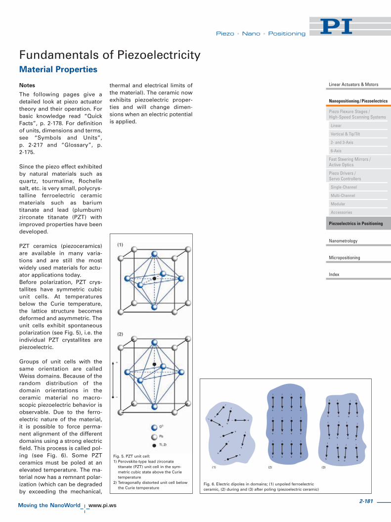
2-181
Piezo • Nano • Positioning
Piezo Flexure Stages /High-Speed Scanning Systems
Nanopositioning / Piezoelectrics
Linear Actuators & Motors
Fast Steering Mirrors /Active Optics
Piezo Drivers /Servo Controllers
Piezoelectrics in Positioning
Nanometrology
Micropositioning
Linear
Vertical & Tip/Tilt
2- and 3-Axis
6-Axis
Single-Channel
Multi-Channel
Modular
Accessories
Index
Fundamentals of PiezoelectricityMaterial Properties
Fig. 5. PZT unit cell:1) Perovskite-type lead zirconate
titanate (PZT) unit cell in the sym-metric cubic state above the Curietemperature
2) Tetragonally distorted unit cell belowthe Curie temperature
Fig. 6. Electric dipoles in domains; (1) unpoled ferroelectricceramic, (2) during and (3) after poling (piezoelectric ceramic)
Notes
The following pages give adetailed look at piezo actuatortheory and their operation. Forbasic knowledge read “QuickFacts”, p. 2-178. For definitionof units, dimensions and terms,see “Symbols and Units”,p. 2-217 and “Glossary”, p.2-175.
Since the piezo effect exhibitedby natural materials such asquartz, tourmaline, Rochellesalt, etc. is very small, polycrys-talline ferroelectric ceramicmaterials such as bariumtitanate and lead (plumbum)zirconate titanate (PZT) withimproved properties have beendeveloped.
PZT ceramics (piezoceramics)are available in many varia-tions and are still the mostwidely used materials for actu-ator applications today.Before polarization, PZT crys-tallites have symmetric cubicunit cells. At temperaturesbelow the Curie temperature,the lattice structure becomesdeformed and asymmetric. Theunit cells exhibit spontaneouspolarization (see Fig. 5), i.e. theindividual PZT crystallites arepiezoelectric.
Groups of unit cells with thesame orientation are calledWeiss domains. Because of therandom distribution of thedomain orientations in theceramic material no macro-scopic piezoelectric behavior isobservable. Due to the ferro-electric nature of the material,it is possible to force perma-nent alignment of the differentdomains using a strong electricfield. This process is called pol-ing (see Fig. 6). Some PZTceramics must be poled at anelevated temperature. The ma-terial now has a remnant polar-ization (which can be degradedby exceeding the mechanical,
thermal and electrical limits ofthe material). The ceramic nowexhibits piezoelectric proper-ties and will change dimen-sions when an electric potentialis applied.

2-182
©P
hys
ikIn
stru
men
te(P
I)G
mb
H&
Co
.KG
2008
.Su
bje
ctto
chan
ge
wit
ho
ut
no
tice
.C
at12
0EIn
spir
atio
ns2
009
08/1
0.18
Piezo • Nano • Positioning
Fundamentals of Piezoelectricity (cont.)
PI develops and manufacturesits own piezo ceramic materialsat the PI Ceramic factory. Themanufacturing process forhigh-voltage piezoceramicstarts with mixing and ballmilling of the raw materials.Next, to accelerate reaction ofthe components, the mixture isheated to 75 % of the sinteringtemperature, and then milledagain. Granulation with thebinder is next, to improve pro-cessing properties. After shap-ing and pressing, the greenceramic is heated to about750 °C to burn out the binder.The next phase is sintering, attemperatures between 1250 °Cand 1350 °C. Then the ceramicblock is cut, ground, polished,lapped, etc., to the desiredshape and tolerance. Elec-trodes are applied by sputter-ing or screen printing process-es. The last step is the polingprocess which takes place in a
heated oil bath at electricalfields up to several kV/mm.Only here does the ceramictake on macroscopic piezoelec-tric properties.
Multilayer piezo actuatorsrequire a different manufactur-ing process. After milling, aslurry is prepared for use in afoil casting process whichallows layer thickness down to20 μm. Next, electrodes arescreen printed and the sheetslaminated. A compactingprocess increases the densityof the green ceramics andremoves air trapped betweenthe layers. The final steps arethe binder burnout, sintering(co-firing) at temperaturesbelow 1100 °C , wire lead ter-mination and poling.
All processes, especially theheating and sintering cycles,must be controlled to very tight
tolerances. The smallest devia-tion will affect the quality andproperties of the PZT material.One hundred percent final test-ing of the piezo material andcomponents at PI Ceramicguarantees the highest possi-ble product quality.
Sputtering facility at PI Ceramic
PZT Ceramics Manufacturing Process
Because of the anisotropicnature of PZT ceramics, piezo-electric effects are dependenton direction. To identify direc-tions, the axes 1, 2, and 3 willbe introduced (correspondingto X, Y, Z of the classical right-hand orthogonal axis set). Theaxes 4, 5 and 6 identify rota-tions (shear), �X, �Y, �Z (alsoknown as U, V, W.)
The direction of polarization(axis 3) is established duringthe poling process by a strongelectrical field applied betweentwo electrodes. For linear actu-ator (translator) applications,the piezo properties along thepoling axis are the most impor-tant (largest deflection).Piezoelectric materials arecharacterized by several coeffi-cients.
Examples are:� dij: Strain coefficients [m/V]
or charge output coefficients[C/N]: Strain developed[m/m] per unit of electricfield strength applied [V/m]or (due to the sensor / actua-tor properties of PZT materi-al) charge density developed[C/m2] per given stress[N/m2].
� gij: Voltage coefficients orfield output coefficients[Vm/N]: Open-circuit electricfield developed [V/m] perapplied mechanical stress[N/m2] or (due to the sensor /actuator properties of PZTmaterial) strain developed[m/m] per applied chargedensity [C/m2].
� kij: Coupling coefficients[dimensionless]. The coeffi-cients are energy ratios
describing the conversionfrom mechanical to electricalenergy or vice versa. k2 is theratio of energy stored(mechanical or electrical) toenergy (mechanical or elec-trical) applied.
Other important parametersare the Young’s modulus Y(describing the elastic proper-ties of the material) and �r therelative dielectric coefficients(permittivity).Double subscripts, as in dij, areused to describe the relation-ships between mechanical andelectrical parameters. The firstindex indicates the direction ofthe stimulus, the second thedirection of the reaction of thesystem.
Example: d33 applies when theelectric field is along the polar-ization axis (direction 3) and
the strain (deflection) is alongthe same axis. d31 applies if theelectric field is in the samedirection as before, but thedeflection of interest is thatalong axis 1 (orthogonal to thepolarization axis).
In addition the superscripts S,T, E, D can be used to describean electrical or mechanicalboundary condition.
Definition:S for strain = constant (mecha-
nically clamped)T for stress = constant (not
clamped)E for field = 0 (short circuit)D for charge displacement (cur-
rent) = 0 (open circuit)
The individual piezoelectriccoefficients are related to eachother by systems of equationsthat will not be explained here.
Definition of Piezoelectric Coefficients and Directions

2-183
Piezo • Nano • Positioning
Piezo Flexure Stages /High-Speed Scanning Systems
Nanopositioning / Piezoelectrics
Linear Actuators & Motors
Fast Steering Mirrors /Active Optics
Piezo Drivers /Servo Controllers
Piezoelectrics in Positioning
Nanometrology
Micropositioning
Linear
Vertical & Tip/Tilt
2- and 3-Axis
6-Axis
Single-Channel
Multi-Channel
Modular
Accessories
Index
Polarisation
Fig. 7. Orthogonal system describing theproperties of a poled piezoelectric ceramic.Axis 3 is the poling direction.
Fig. 8. Smooth response of a P-170 HVPZT translator to a 1 V, 200 Hz triangu-lar drive signal. Note that one division is only 2 nanometers
Notes
The piezoelectric coefficientsdescribed here are often pre-sented as constants. It shouldbe clearly understood that theirvalues are not invariable. Thecoefficients describe materialproperties under small-signalconditions only. They vary withtemperature, pressure, electricfield, form factor, mechanicaland electrical boundary condi-tions, etc. Compound compo-nents, such as piezo stack actu-ators, let alone preloaded actu-ators or lever-amplified sys-tems, cannot be described suf-ficiently by these materialparameters alone. This is why
each component or systemmanufactured by PI is accom-panied by specific data such asstiffness, load capacity, dis-placement, resonant frequen-cy, etc., determined by individ-ual measurements. The param-eters describing these systemsare to be found in the technicaldata table for the product.Important: There are no inter-national standards for definingthese specifications. Thismeans that claims of differentmanufacturers can not neces-sarily be compared directlywith one another.
Since the displacement of apiezo actuator is based on ionicshift and orientation of the PZTunit cells, the resolutiondepends on the electrical fieldapplied. Resolution is theoreti-cally unlimited. Because thereare no threshold voltages, thestability of the voltage source iscritical; noise even in the μVrange causes position changes.When driven with a low-noiseamplifier, piezo actuators canbe used in tunneling and atom-ic force microscopes providingsmooth, continuous motionwith sub-atomic resolution (seeFig. 8).
Amplifier Noise
One factor determining theposition stability (resolution) ofa piezo actuator is noise in thedrive voltage. Specifying thenoise value of the piezo driverelectronics in millivolts, how-ever, is of little practical usewithout spectral information. Ifthe noise occurs in a frequencyband far beyond the resonantfrequency of the mechanicalsystem, its influence onmechanical resolution and sta-
bility can be neglected. If itcoincides with the resonant fre-quency, it will have a far moresignificant influence on the sys-tem stability.
Therefore, meaningful infor-mation about the stability andresolution of a piezo position-ing system can only beacquired if the resolution of thecomplete system—piezo actua-tor and drive electronics—ismeasured in terms of nanome-ters rather than millivolts. Forfurther information see p. 2-10and p. 2-199 ff.
Notes
The smooth motion in the sub-nanometer range shown inFig. 8 can only be attained byfrictionless and stictionlesssolid state actuators and guid-ance such as piezo actuatorsand flexures. “Traditional”technologies used in motionpositioners (stepper or DCservo-motor drives in combina-tion with dovetail slides, ballbearings, and roller bearings)all have excessive amounts offriction and stiction. This fun-
damental property limits reso-lution, causes wobble, hystere-sis, backlash, and an uncertain-ty in position repeatability.Their practical usefulness isthus limited to a precision ofseveral orders of magnitudebelow that obtainable with PIpiezo nanopositioners.
Resolution

2-184
©P
hys
ikIn
stru
men
te(P
I)G
mb
H&
Co
.KG
2008
.Su
bje
ctto
chan
ge
wit
ho
ut
no
tice
.C
at12
0EIn
spir
atio
ns2
009
08/1
0.18
Piezo • Nano • Positioning
©P
hys
ikIn
stru
men
te(P
I)G
mb
H&
Co
.KG
2008
.Su
bje
ctto
chan
ge
wit
ho
ut
no
tice
.C
at12
0EIn
spir
atio
ns2
009
08/1
0.18
Fundamentals of Piezomechanics
Commonly used stack actua-tors achieve a relative displace-ment of up to 0.2 %.Displacement of piezoceramicactuators is primarily a func-tion of the applied electric fieldstrength E, the length L of theactuator, the forces applied to itand the properties of the piezo-electric material used. Thematerial properties can bedescribed by the piezoelectricstrain coefficients dij. Thesecoefficients describe the rela-tionship between the appliedelectric field and the mechani-cal strain produced.
The change in length, �L, of anunloaded single-layer piezoactuator can be estimated bythe following equation:
(Equation 1)
Where:
S = strain (relative lengthchange �L/L, dimen-sionless)
L0 = ceramic length [m]E = electric field strength
[V/m]dij = piezoelectric coeffi-
cient of the material[m/V]
d33 describes the strain parallelto the polarization vector of theceramics (thickness) and isused when calculating the dis-placement of stack actuators;d31 is the strain orthogonal tothe polarization vector (width)and is used for calculating tubeand strip actuators (see Fig. 9).d33 and d31 are sometimesreferred to as “piezo gain”.
Notes
For the materials used in stan-dard PI piezo actuators, d33is on the order of 250 to550 pm/V, d31 is on the order of
-180 to -210 pm/V. The highestvalues are attainable withshear actuators in d15 mode.These figures only apply to theraw material at room tempera-ture under small-signal condi-tions.
The maximum allowable fieldstrength in piezo actuators isbetween 1 and 2 kV/mm in thepolarization direction. In thereverse direction (semi-bipolaroperation), at most 300 V/mmis allowable (see Fig. 10). Themaximum voltage depends onthe ceramic and insulationmaterials.
Exceeding the maximum volt-age may cause dielectric break-down and irreversible damageto the piezo actuator.
With the reverse field, negativeexpansion (contraction) occurs,giving an additional 20 % of thenominal displacement. If boththe regular and reverse fieldsare used, a relative expansion(strain) up to 0.2 % is achiev-able with piezo stack actuators.This technique can reduce theaverage applied voltage with-out loss of displacement andthereby increase piezo lifetime.
Stacks can be built with aspectratios up to 12:1(length:diameter). This meansthat the maximum travel rangeof an actuator with 15 mmpiezo diameter is limited toabout 200 μm. Longer travelranges can be achieved bymechanical amplification tech-niques (see “Lever MotionAmplifiers” p. 2-210).
Polarisation
Fig. 9. Expansion and contraction of a piezoelectric disk in response to an appliedvoltage. Note that d31, which describes the lateral motion, �D, is negative
V
Fig. 10. Typical response of a “soft PZT” actuator to a bipolar drivevoltage. When a certain threshold voltage negative to the polarizationdirection is exceeded, reversal of polarization can occur
Displacement of Piezo Actuators (Stack & Contraction Type)
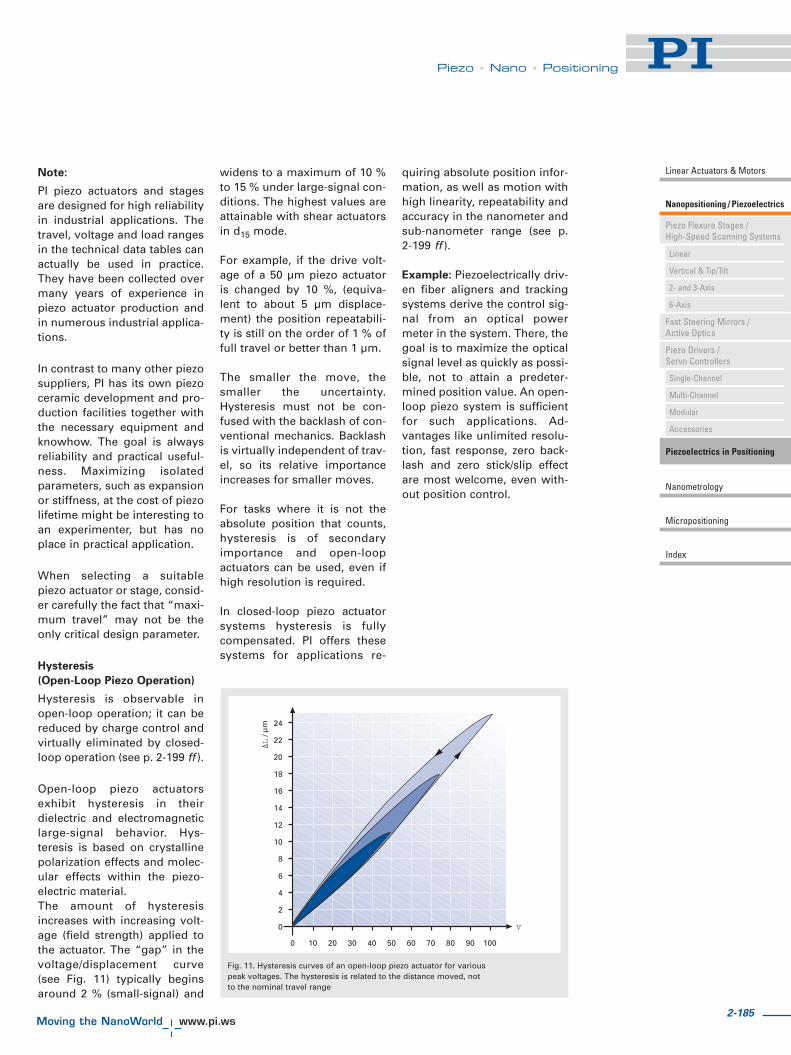
2-185
Piezo • Nano • Positioning
Piezo Flexure Stages /High-Speed Scanning Systems
Nanopositioning / Piezoelectrics
Linear Actuators & Motors
Fast Steering Mirrors /Active Optics
Piezo Drivers /Servo Controllers
Piezoelectrics in Positioning
Nanometrology
Micropositioning
Linear
Vertical & Tip/Tilt
2- and 3-Axis
6-Axis
Single-Channel
Multi-Channel
Modular
Accessories
Index
Note:
PI piezo actuators and stagesare designed for high reliabilityin industrial applications. Thetravel, voltage and load rangesin the technical data tables canactually be used in practice.They have been collected overmany years of experience inpiezo actuator production andin numerous industrial applica-tions.
In contrast to many other piezosuppliers, PI has its own piezoceramic development and pro-duction facilities together withthe necessary equipment andknowhow. The goal is alwaysreliability and practical useful-ness. Maximizing isolatedparameters, such as expansionor stiffness, at the cost of piezolifetime might be interesting toan experimenter, but has noplace in practical application.
When selecting a suitablepiezo actuator or stage, consid-er carefully the fact that “maxi-mum travel” may not be theonly critical design parameter.
Hysteresis
(Open-Loop Piezo Operation)
Hysteresis is observable inopen-loop operation; it can bereduced by charge control andvirtually eliminated by closed-loop operation (see p. 2-199 ff ).
Open-loop piezo actuatorsexhibit hysteresis in theirdielectric and electromagneticlarge-signal behavior. Hys-teresis is based on crystallinepolarization effects and molec-ular effects within the piezo-electric material.The amount of hysteresisincreases with increasing volt-age (field strength) applied tothe actuator. The “gap” in thevoltage/displacement curve(see Fig. 11) typically beginsaround 2 % (small-signal) and
widens to a maximum of 10 %to 15 % under large-signal con-ditions. The highest values areattainable with shear actuatorsin d15 mode.
For example, if the drive volt-age of a 50 μm piezo actuatoris changed by 10 %, (equiva-lent to about 5 μm displace-ment) the position repeatabili-ty is still on the order of 1 % offull travel or better than 1 μm.
The smaller the move, thesmaller the uncertainty.Hysteresis must not be con-fused with the backlash of con-ventional mechanics. Backlashis virtually independent of trav-el, so its relative importanceincreases for smaller moves.
For tasks where it is not theabsolute position that counts,hysteresis is of secondaryimportance and open-loopactuators can be used, even ifhigh resolution is required.
In closed-loop piezo actuatorsystems hysteresis is fullycompensated. PI offers thesesystems for applications re-
quiring absolute position infor-mation, as well as motion withhigh linearity, repeatability andaccuracy in the nanometer andsub-nanometer range (see p.2-199 ff ).
Example: Piezoelectrically driv-en fiber aligners and trackingsystems derive the control sig-nal from an optical powermeter in the system. There, thegoal is to maximize the opticalsignal level as quickly as possi-ble, not to attain a predeter-mined position value. An open-loop piezo system is sufficientfor such applications. Ad-vantages like unlimited resolu-tion, fast response, zero back-lash and zero stick/slip effectare most welcome, even with-out position control.
V
L
Fig. 11. Hysteresis curves of an open-loop piezo actuator for variouspeak voltages. The hysteresis is related to the distance moved, notto the nominal travel range

2-186
©P
hys
ikIn
stru
men
te(P
I)G
mb
H&
Co
.KG
2008
.Su
bje
ctto
chan
ge
wit
ho
ut
no
tice
.C
at12
0EIn
spir
atio
ns2
009
08/1
0.18
Piezo • Nano • Positioning
Creep / Drift (Open-Loop Piezo
Operation)
The same material propertiesresponsible for hysteresis alsocause creep or drift. Creep is achange in displacement withtime without any accompany-ing change in the control volt-age. If the operating voltage ofa piezo actuator is changed,the remnant polarization (piezogain) continues to change,manifesting itself in a slowchange of position. The rate ofcreep decreases logarithmical-ly with time (see Fig. 12). Thefollowing equation describesthis effect:
(Equation 2)
Creep of PZT motion as a func-tion of time.
Where:
t = time [s]�L(t) = change in position
as a function oftime
�Lt= 0.1 = displacement 0.1seconds after thevoltage change iscomplete [m].
= creep factor,which is depend-ent on the proper-ties of the actua-tor (on the orderof 0.01 to 0.02,which is 1 %to 2 % pertime decade).
In practice, maximum creep(after a few hours) can add upto a few percent of the com-manded motion.
Aging
Aging refers to reduction inremnant polarization; it can bean issue for sensor or charge-generation applications (direct
piezo effect). With actuatorapplications it is negligible,because repoling occurs everytime a higher electric field isapplied to the actuator materialin the poling direction.
Note
For periodic motion, creep andhysteresis have only a minimaleffect on repeatability.
Fundamentals of Piezomechanics (cont.)
Fig. 12. Creep of open-loop PZT motion after a 60 μm change in length as a functionof time. Creep is on the order of 1 % of the last commanded motion per time decade

2-187
Piezo • Nano • Positioning
Piezo Flexure Stages /High-Speed Scanning Systems
Nanopositioning / Piezoelectrics
Linear Actuators & Motors
Fast Steering Mirrors /Active Optics
Piezo Drivers /Servo Controllers
Piezoelectrics in Positioning
Nanometrology
Micropositioning
Linear
Vertical & Tip/Tilt
2- and 3-Axis
6-Axis
Single-Channel
Multi-Channel
Modular
Accessories
Index
Metrology for Nanopositioning Systems
There are two basic techniquesfor determining the position ofpiezoelectric motion systems:Direct metrology and indirectmetrology.
Indirect (Inferred) Metrology
Indirect metrology involvesinferring the position of theplatform by measuring posi-tion or deformation at the actu-ator or other component in thedrive train. Motion inaccuracieswhich arise between the driveand the platform can not beaccounted for.
Direct Metrology
With direct metrology, howev-er, motion is measured at the
point of interest; this can bedone, for example, with aninterferometer or capacitivesensor.Direct metrology is more accu-rate and thus better suited toapplications which needabsolute position measure-ments. Direct metrology alsoeliminates phase shiftsbetween the measuring pointand the point of interest. Thisdifference is apparent in high-er-load, multi-axis dynamicapplications.
Parallel and Serial Metrology
In multi-axis positioning sys-tems parallel and serial metrolo-gy must also be distinguished.
With parallel metrology, allsensors measure the positionof the same moving platformagainst the same stationary ref-erence. This means that allmotion is inside the servo-loop,no matter which actuatorcaused it (see Active TrajectoryControl). Parallel metrologyand parallel kinematics can beeasily integrated.
With serial metrology the refer-ence plane of one or more sen-sors is moved by one or moreactuators. Because the off-axismotion of any moving refer-ence plane is never measured,it can not be compensated.See also p. 2-8 ff.
High-Resolution Sensors
Strain Gauge Sensors
SGS sensors are an implemen-tation of inferred metrologyand are typically chosen forcost-sensitive applications. AnSGS sensor consists of a resis-tive film bonded to the piezostack or a guidance element;the film resistance changeswhen strain occurs. Up to fourstrain gauges (the actual con-figuration varies with the actu-ator construction) form aWheatstone bridge driven by aDC voltage (5 to 10 V). Whenthe bridge resistance changes,the sensor electronics convertsthe resulting voltage changeinto a signal proportional to thedisplacement.
A special type of SGS is knownas a piezoresistive sensor. Ithas good sensitivity, butmediocre linearity and temper-ature stability. See also p. 2-8 ff.
Resolution: better than 1 nm(for short travel ranges, up toabout 15 μm)
Bandwidth: to 5 kHz
Advantages
� High Bandwidth� Vacuum Compatible� Highly Compact
Other characteristics:
� Low heat generation (0.01 to0.05 W sensor excitationpower)
� Long-term position stabilitydepends on adhesive quality
� Indirect metrology
Examples
Most PI LVPZT and HVPZT actua-tors are available with straingauge sensors for closed-loopcontrol (see the “Piezo Actuators& Components” section p. 1-61 ff ).
Note
The sensor bandwidth for thesensors described here shouldnot be confused with the band-width of the piezo mechanicsservo-control loop, which isfurther limited by the electronicand mechanical properties ofthe system.
Fig. 13. Strain gauge sensors.Paper clip for size comparison
Actuators and Sensors

2-188
©P
hys
ikIn
stru
men
te(P
I)G
mb
H&
Co
.KG
2008
.Su
bje
ctto
chan
ge
wit
ho
ut
no
tice
.C
at12
0EIn
spir
atio
ns2
009
08/1
0.18
Piezo • Nano • Positioning
Actuators and Sensors (cont.)
Linear Variable Differential
Transformers (LVDTs)
LVDTs are well suited for directmetrology. A magnetic core,attached to the moving part,determines the amount ofmagnetic energy induced fromthe primary windings into thetwo differential secondarywindings (Fig. 15). The carrierfrequency is typically 10 kHz.
Resolution: to 5 nm
Bandwidth: to 1 kHz
Repeatability: to 5 nm
Advantages:
� Good temperature stability� Very good long-term
stability� Non-contacting
� Controls the position of themoving part rather than theposition of the piezo stack
� Cost-effective
Other characteristics:
� Outgassing of insulationmaterials may limit applica-tions in very high vacuum
� Generates magnetic field
Capacitive Position Sensors
Capacitive sensors are themetrology system of choice forthe most demanding applica-tions.
Two-plate capacitive sensorsconsist of two RF-excitedplates that are part of a capaci-tive bridge (Fig. 17). One plateis fixed, the other plate is con-nected to the object to be posi-tioned (e.g. the platform of astage). The distance betweenthe plates is inversely propor-tional to the capacitance, fromwhich the displacement is cal-culated. Short-range, two-platesensors can achieve resolutionon the order of picometers.See the “Nanometrology”section (p. 3-1 ff ). for details.
Resolution: Better than 0.1 nmpossible
Repeatability: Better than0.1 nm possible
Bandwidth: Up to 10 kHz
Advantages:
� Highest resolution of allcommercially available sen-sors
� Ideally suited for parallelmetrology
� Non-contacting� Excellent long-term stability� Excellent frequency response� No magnetic field� Excellent linearity
Other characteristics:
� Ideally suited for integrationin flexure guidance systems,which maintain the neces-sary parallelism of the pla-tes. Residual tip/tilt errorsare greatly reduced by theILS linearization system (seep. 3-18) developed by PI.
Fig. 15. Working principle of an LVDT sensor Fig. 17. Working principle of two-plate capacitive position sensors
Fig. 16. Capacitive sensors canattain resolution 10,000 times
better than calipersFig. 14. LVDT sensor, coil and core. Paper
clip for size comparison
Examples
P-733 parallel kinematic nano-positioning system with paral-lel metrology (see p. 2-62).P-753 LISA NanoAutomation®
actuators (see p. 2-16); addi-tional examples in the “PiezoFlexure Stages / High-SpeedScanning Systems” section.

2-189
Piezo • Nano • Positioning
Piezo Flexure Stages /High-Speed Scanning Systems
Nanopositioning / Piezoelectrics
Linear Actuators & Motors
Fast Steering Mirrors /Active Optics
Piezo Drivers /Servo Controllers
Piezoelectrics in Positioning
Nanometrology
Micropositioning
Linear
Vertical & Tip/Tilt
2- and 3-Axis
6-Axis
Single-Channel
Multi-Channel
Modular
Accessories
Index
Fundamentals of Piezoelectric ActuatorsForces and Stiffness
Maximum Applicable Forces
(Compressive Load Limit,
Tensile Load Limit)
The mechanical strength val-ues of PZT ceramic material(given in the literature) areoften confused with the practi-cal long-term load capacity of apiezo actuator. PZT ceramicmaterial can withstand pres-sures up to 250 MPa (250 x 106
N/m2) without breaking. Thisvalue must never beapproached in practical appli-cations, however, becausedepolarization occurs at pres-sures on the order of 20 % to30 % of the mechanical limit.For stacked actuators andstages (which are a combina-tion of several materials) addi-tional limitations apply. Para-meters such aspect ratio, buck-ling, interaction at the inter-faces, etc. must be considered.
The load capacity data listedfor PI actuators are conserva-tive values which allow longlifetime.
Tensile loads of non-preloadedpiezo actuators are limited to5% to 10% of the compressiveload limit. PI offers a variety ofpiezo actuators with internalspring preload for increasedtensile load capacity. Preloadedelements are highly recom-mended for dynamic applica-tions.
The PZT ceramic is especiallysensitive to shear forces; theymust be intercepted by exter-nal measures (flexure guides,etc.).
Stiffness
Actuator stiffness is an impor-tant parameter for calculatingforce generation, resonant fre-quency, full-system behavior,etc. The stiffness of a solidbody depends on Young’smodulus of the material. Stiff-
ness is normally expressed interms of the spring constant kT,which describes the deforma-tion of the body in response toan external force.
This narrow definition is of lim-ited application for piezoce-ramics because the cases ofstatic, dynamic, large-signaland small-signal operationwith open and shorted elec-trodes must all be distin-guished. The poling process ofpiezoceramics leaves a rem-nant strain in the materialwhich depends on the magni-tude of polarization. The pola-
rization is affected by both theapplied voltage and externalforces. When an external forceis applied to poled piezoceram-ics, the dimensional changedepends on the stiffness of theceramic material and thechange of the remnant strain(caused by the polarizationchange). The equation �LN =F/kT is only valid for smallforces and small-signal condi-tions. For larger forces, anadditional term, describing theinfluence of the polarizationchanges, must be super-
imposed on the stiffness (kT).Since piezo ceramics are activematerials, they produce anelectrical response (charge)when mechanically stressed(e.g. in dynamic operation). Ifthe electric charge cannot bedrained from the PZT ceramics,it generates a counterforceopposing the mechanicalstress. This is why a piezo ele-ment with open electrodesappears stiffer than one withshorted electrodes. Commonvoltage amplifiers with theirlow output impedances looklike a short circuit to a piezoactuator.
Mechanical stressing of piezoactuators with open electrodes,e.g. open wire leads, should beavoided, because the resultinginduced voltage might damagethe stack electrically.
Fig. 18. Quasi-static characteristic mechanical stress/strain curves for piezo ceramic actua-tors and the derived stiffness values. Curve 1 is with the nominal operating voltage on theelectrodes, Curve 2 is with the electrodes shorted (showing ceramics after depolarization)
Note
There is no international stan-dard for measuring piezo actu-ator stiffness. Therefore stiff-ness data from different manu-facturers cannot be comparedwithout additional information.

2-190
©P
hys
ikIn
stru
men
te(P
I)G
mb
H&
Co
.KG
2008
.Su
bje
ctto
chan
ge
wit
ho
ut
no
tice
.C
at12
0EIn
spir
atio
ns2
009
08/1
0.18
Piezo • Nano • Positioning
Fundamentals of Piezoelectric Actuators (cont.)
Force Generation
In most applications, piezoactuators are used to producedisplacement. If used in arestraint, they can be used togenerate forces, e.g. for stamp-ing. Force generation is alwayscoupled with a reduction in dis-placement. The maximumforce (blocked force) a piezoactuator can generate dependson its stiffness and maximumdisplacement (see also p. 2-191).At maximum force generation,displacement drops to zero.
(Equation 3)
Maximum force that can begenerated in an infinitely rigidrestraint (infinite spring con-stant).
Where:
�L0 = max. nominal displace-ment without externalforce or restraint [m]
kT = piezo actuator stiffness[N/m]
In actual applications thespring constant of the load canbe larger or smaller than thepiezo spring constant. Theforce generated by the piezoactuator is:
(Equation 4)
Effective force a piezo actuatorcan generate in a yieldingrestraint
Where:
�L0 = max. nominal displace-ment without externalforce or restraint [m]
kT = piezo actuator stiffness[N/m]
kS = stiffness of externalspring [N/m]
Example
What is the force generation ofa piezo actuator with nominaldisplacement of 30 μm andstiffness of 200 N/μm? Thepiezo actuator can produce amaximum force of 30 μm x 200N/μm = 6000 N When forcegeneration is maximum, dis-placement is zero and viceversa (see Fig. 19 for details).
Example
A piezo actuator is to be usedin a nano imprint application.At rest (zero position) the dis-tance between the piezo actua-tor tip and the material is 30microns (given by mechanicalsystem tolerances). A force of500 N is required to embossthe material.
Q: Can a 60 μm actuator with astiffness of 100 N/μm be used?
A: Under ideal conditionsthis actuator can generate aforce of 30 x 100 N = 3000 N(30 microns are lost motiondue to the distance between
the sheet and the piezo actua-tor tip). In practice the forcegeneration depends on thestiffness of the metal and thesupport. If the support were asoft material, with a stiffness of10 N/μm, the piezo actuatorcould only generate a force of300 N onto the metal whenoperated at maximum drivevoltage. If the support werestiff but the material to beembossed itself were very softit would yield and the piezoactuator still could not gener-ate the required force. If boththe support and the metal werestiff enough, but the piezo actu-ator mount was too soft, theforce generated by the piezowould push the actuator awayfrom the material to beembossed.
The situation is similar to liftinga car with a jack. If the ground(or the car’s body) is too soft,the jack will run out of travelbefore it generates enoughforce to lift the wheels off theground.
Fig. 19. Force generation vs. dis-placement of a piezo actuator (dis-placement 30 μm, stiffness 200N/μm). Stiffness at various operat-ing voltages. The points where thedashed lines (external springcurves) intersect the piezo actua-tor force/displacement curvesdetermine the force and displace-ment for a given setup with anexternal spring. The stiffer theexternal spring (flatter dashedline), the less the displacementand the greater the force gener-ated by the actuator. Maximumwork can be done when the stiff-ness of the piezo actuator andexternal spring are identical

2-191
Piezo • Nano • Positioning
Displacement and
External Forces
Like any other actuator, a piezoactuator is compressed when aforce is applied. Two casesmust be considered when oper-ating a piezo actuator with aload:
a) The load remains constantduring the motion process.
b) The load changes during themotion process.
Note
To keep down the loss of travel,the stiffness of the preloadspring should be under 1/10that of the piezo actuator stiff-ness. If the preload stiffnesswere equal to the piezo actua-tor stiffness, the travel wouldbe reduced by 50 %. For prima-rily dynamic applications, theresonant frequency of the pre-load must be above that of thepiezo actuator.
aConstant Force
Zero-point is offset
A mass is installed on thepiezo actuator which appliesa force F = M · g (M is themass, g the acceleration dueto gravity).The zero-point will be shiftedby �LN ≈ F/kT, where kT is thestiffness of the actuator.If this force is below the spe-cified load limit (see producttechnical data), full displace-ment can be obtained at fulloperating voltage (see Fig. 20).
(Equation 5)
Zero-point offset with con-stant force
Where:
�LN = zero-point offset [m]F = force (mass x accel-
eration due to gravi-ty) [N]
kT = piezo actuator stiff-ness [N/m]
Example
How large is the zero-pointoffset of a 30 μm piezo actua-tor with a stiffness of 100N/μm if a load of 20 kg is
applied, andwhat is themaximum dis-placement withthis load?
The load of20 kg generatesa force of 20 kgx 9.81 m/s2 =196 N. Witha stiffness of
100 N/μm, the piezo actuatoris compressed slightly lessthan 2 μm. The maximumdisplacement of 30 μm is notreduced by this constantforce.
Example
Q: What is the maximum dis-placement of a 15 μm piezotranslator with a stiffness of50 N/μm, mounted in an elas-tic restraint with a springconstant kS (stiffness) of100 N/μm?
A: Equation 6 shows that thedisplacement is reduced in anelastic restraint. The springconstant of the externalrestraint is twice the value ofthe piezo translator. Theachievable displacement istherefore limited to 5 μm(1/3 of the nominal travel).
b Changing Force
Displacement is reduced
For piezo actuator operationagainst an elastic load differ-ent rules apply. Part of thed i s p l a c e -ment gene-rated by thepiezo effectis lost dueto the elas-ticity of thepiezo ele-ment (Fig.21). The to-tal avail-able displa-cement canbe related to the spring stiff-ness by the following equa-tions:
(Equation 6)
Maximum displacement of apiezo actuator acting againsta spring load.
(Equation 7)
Maximum loss of displace-ment due to external springforce. In the case where therestraint is infinitely rigid (ks
= ∞), the piezo actuator canproduce no displacement butacts only as a force generator.
Where:
�L = displacement with ex-ternal spring load [m]
�L0 = nominal displacementwithout external forceor restraint [m]
�LR = lost displacementcaused by the exter-nal spring [m]
ks = spring stiffness [N/m]
kT = piezo actuator stiff-ness [N/m]
Fig. 21. Case b: Effectivedisplacement of a piezo actua-
tor acting against a spring load
M
Fig. 20. Case a: Zero-point offsetwith constant force

2-192
©P
hys
ikIn
stru
men
te(P
I)G
mb
H&
Co
.KG
2008
.Su
bje
ctto
chan
ge
wit
ho
ut
no
tice
.C
at12
0EIn
spir
atio
ns2
009
08/1
0.18
Piezo • Nano • Positioning
Dynamic Operation Fundamentals
Dynamic Forces
Every time the piezo drive volt-age changes, the piezo elementchanges its dimensions. Due tothe inertia of the piezo actuatormass (plus any additionalload), a rapid move will gener-ate a force acting on (pushingor pulling) the piezo. The maxi-mum force that can be generat-ed is equal to the blocked force,described by:
(Equation 8)
Maximum force available toaccelerate the piezo mass plusany additional load. Tensileforces must be compensated,for example, by a spring pre-load.
Where:
Fmax = max. force [N]
�L0 = max. nominal displace-ment without externalforce or restraint [m]
kT = piezo actuator stiffness[N/m]
The preload force should bearound 20% of the compressiveload limit. The preload shouldbe soft compared to the piezoactuator, at most 10% the actu-ator stiffness.In sinusoidal operation peakforces can be expressed as:
(Equation 9)
Dynamic forces on a piezoactuator in sinusoidal opera-tion at frequency f.
Where:
Fdyn = dynamic force [N]meff = effective mass [kg],
see p. 4-25�L = peak-to-peak displace-
ment [m]f = frequency [Hz]
The maximum permissibleforces must be consideredwhen choosing an operatingfrequency.
Example:
Dynamic forces at 1000 Hz, 2 mpeak-to-peak and 1 kg loadreach approximately ±40 N.
Fig. 22. Recommended guiding for large masses
Note
A guiding system (e.g.diaphragm type) is essentialwhen loads which are heavy orlarge (relative to the piezo actu-ator diameter) are moveddynamically. Without a guidingsystem, there is a potential fortilt oscillations that may dam-age the piezoceramics.

2-193
Piezo • Nano • Positioning
Piezo Flexure Stages /High-Speed Scanning Systems
Nanopositioning / Piezoelectrics
Linear Actuators & Motors
Fast Steering Mirrors /Active Optics
Piezo Drivers /Servo Controllers
Piezoelectrics in Positioning
Nanometrology
Micropositioning
Linear
Vertical & Tip/Tilt
2- and 3-Axis
6-Axis
Single-Channel
Multi-Channel
Modular
Accessories
Index
Fig. 23. Effective mass of an actuator fixed at one end
Resonant Frequency
In general, the resonant fre-quency of any spring/mass sys-tem is a function of its stiffnessand effective mass (see Fig.23). Unless otherwise stated,the resonant frequency givenin the technical data tables foractuators always refer to theunloaded actuator with oneend rigidly attached. For piezopositioning systems, the datarefers to the unloaded systemfirmly attached to a significant-ly larger mass.
(Equation 10)
Resonant frequency of an idealspring/mass system.
Where:
fO = resonant frequency ofunloaded actuator [Hz]
kT = piezo actuator stiffness[N/m]
meff = effective mass (about1/3 of the mass of theceramic stack plus anyinstalled end pieces)[kg]
Note:
In positioning applications,piezo actuators are operatedwell below their resonant fre-quencies. Due to the non-idealspring behavior of piezoceram-ics, the theoretical result fromthe above equation does notnecessarily match the real-world behavior of the piezoactuator system under largesignal conditions. Whenadding a mass M to the actua-tor, the resonant frequencydrops according to the follow-ing equation:
(Equation 11)
Resonant frequency withadded mass.
m´eff = additional massM + meff.
The above equations show thatto double the resonant fre-quency of a spring-mass sys-tem, it is necessary to eitherincrease the stiffness by a fac-tor of 4 or decrease the effec-tive mass to 25 % of its originalvalue. As long as the resonantfrequency of a preload spring
is well above that of the actua-tor, forces it introduces do notsignificantly affect the actua-tor’s resonant frequency.
The phase response of a piezoactuator system can be approx-imated by a second order sys-tem and is described by the fol-lowing equation:
(Equation 12)
Where:
� = phase angle [deg]
Fmax = resonant frequency [Hz]
f = operating frequency[Hz]

2-194
©P
hys
ikIn
stru
men
te(P
I)G
mb
H&
Co
.KG
2008
.Su
bje
ctto
chan
ge
wit
ho
ut
no
tice
.C
at12
0EIn
spir
atio
ns2
009
08/1
0.18
Piezo • Nano • Positioning
How Fast Can a Piezo
Actuator Expand?
Fast response is one of thecharacteristic features of piezoactuators. A rapid drive voltagechange results in a rapid posi-tion change. This property isespecially welcome in dynamicapplications such as scanningmicroscopy, image stabiliza-tion, switching ofvalves/shutters, shock-wavegeneration, vibration cancella-tion systems, etc.
A piezo actuator can reach itsnominal displacement inapproximately 1/3 of the periodof the resonant frequency, pro-vided the controller can deliverthe necessary current. If notcompensated by appropriatemeasures (e.g. notch filter,InputShaping®, see p. 2-201) in
the servo-loop, such rapidexpansion will be accompaniedby significant overshoot.
(Equation 13)
Minimum rise time of a piezoactuator (requires an amplifierwith sufficient output currentand slew rate).
Where:
Tmin = time [s]
f0 = resonant frequency[Hz]]
Example: A piezo translatorwith a 10 kHz resonant frequen-cy can reach its nominal dis-placement within 30 μs.
Dynamic Operation Fundamentals (cont.)
Fig. 24. Response of an undamped, lever-amplified piezo actuator (low resonant frequency) to a rapid drive-voltage change. Thisbehavior can be prevented by intelligent control techniques or position servo-control

2-195
Piezo • Nano • Positioning
Piezo Flexure Stages /High-Speed Scanning Systems
Nanopositioning / Piezoelectrics
Linear Actuators & Motors
Fast Steering Mirrors /Active Optics
Piezo Drivers /Servo Controllers
Piezoelectrics in Positioning
Nanometrology
Micropositioning
Linear
Vertical & Tip/Tilt
2- and 3-Axis
6-Axis
Single-Channel
Multi-Channel
Modular
Accessories
Index
Piezo Actuator Electrical Fundamentals
Fig. 25. Design of a piezo stack actuator
Electrical Requirements for Piezo Operation
General
When operated well below theresonant frequency, a piezoactuator behaves as a capaci-tor: The actuator displacementis proportional to stored charge(first order estimate). Thecapacitance of the actuatordepends on the area and thick-ness of the ceramic, as well ason its material properties. Forpiezo stack actuators, whichare assembled with thin, lami-nar wafers of electroactiveceramic material electricallyconnected in parallel, thecapacitance also depends onthe number of layers.
The small-signal capacitance ofa stack actuator can be estimat-ed by:
(Equation 14)
Where:
C = capacitance [F (As/V)]
n = number of layers =
�33T = dielectric constant[As/Vm]
A = electrode surface areaof a single layer [m2]
dS = distance between theindividual electrodes(layer-thickness) [m]
I0 = actuator length
The equation shows that for agiven actuator length, thecapacitance increases with thesquare of the number of layers.Therefore, the capacitance of apiezo actuator constructed of100 μm thick layers is 100 timesthe capacitance of an actuatorwith 1 mm layers, if the twoactuators have the samedimensions. Although the actu-ator with thinner layers draws
100 times as much current, thepower requirements of the twoactuators in this example areabout the same. The PI high-voltage and low-voltage ampli-fiers in this catalog are de-signed to meet the require-ments of the respective actua-tor types.
Static Operation
When electrically charged, theamount of energy stored in thepiezo actuator is E = (1/2) CU2
Every change in the charge(and therefore in displacement)of the PZT ceramics requires acurrent i:
(Equation 15)
Relationship of current andvoltage for the piezo actuator
Where:
i = current [A]
Q = charge [coulomb (As)]
C = capacitance [F]
U = voltage [V]
t = time [s]
For static operation, only theleakage current need be sup-plied. The high internal resist-ance reduces leakage currentsto the micro-amp range or less.Even when suddenly discon-nected from the electricalsource, the charged actuatorwill not make a sudden move,but return to its unchargeddimensions very slowly.
For slow position changes,only very low current isrequired.
Example: An amplifier with anoutput current of 20 μA canfully expand a 20 nF actuator in
one second. Suitable amplifierscan be found using the “PiezoDrivers / Servo Controllers”Selection Guide on p. 2-100 ff.
Note
The actuator capacitance val-ues indicated in the technicaldata tables are small-signal val-ues (measured at 1 V, 1000 Hz,20 °C, unloaded) The capaci-tance of piezoceramics chan-ges with amplitude, tempera-ture, and load, to up to 200 % ofthe unloaded, small-signal,room-temperature value. Fordetailed information on powerrequirements, refer to theamplifier frequency responsecurves in the “Piezo Drivers /Servo Controllers” (see p.2-99 ff ) section.

2-196
©P
hys
ikIn
stru
men
te(P
I)G
mb
H&
Co
.KG
2008
.Su
bje
ctto
chan
ge
wit
ho
ut
no
tice
.C
at12
0EIn
spir
atio
ns2
009
08/1
0.18
Piezo • Nano • Positioning
Dynamic Operation (Linear)
Piezo actuators can provideaccelerations of thousands ofg’s and are ideally suited fordynamic applications.
Several parameters influencethe dynamics of a piezo posi-tioning system:
� The slew rate [V/s] and themaximum current capacityof the amplifier limit theoperating frequency of thepiezo system.
� If sufficient electrical poweris available from the amplifi-er, the maximum drive fre-quency may be limited bydynamic forces (see “Dyna-mic Operation”, p. 2-192).
� In closed-loop operation, themaximum operating fre-quency is also limited by thephase and amplituderesponse of the system. Ruleof thumb: The higher thesystem resonant frequency,the better the phase andamplitude response, and thehigher the maximum usablefrequency. The sensor band-width and performance ofthe servo-controller (digitaland analog filters, controlalgorithm, servo-bandwidth)determine the maximumoperating frequency of apiezoelectric system.
� In continuous operation,heat generation can alsolimit the operating frequency.
The following equationsdescribe the relationshipbetween amplifier output cur-rent, voltage and operating fre-quency. They help determinethe minimum specifications ofa piezo amplifier for dynamicoperation.
(Equation 16)
Long-term average currentrequired for sinusoidal opera-tion
(Equation 17)
Peak current required for sinu-soidal operation
(Equation 18)
Maximum operating frequencywith triangular waveform, as afunction of the amplifier outputcurrent limit
Where:
ia* = average amplifiersource/sink current [A]
imax* = peak amplifiersource/sink current [A]
fmax = maximum operatingfrequency [Hz]
C** = piezo actuator capaci-tance [Farad (As/V)]
Up-p = peak-to-peak drivevoltage [V]
f = operating frequency[Hz]
The average and maximumcurrent capacity for each PIpiezo amplifier can be found inthe product technical datatables.
Example
Q: What peak current isrequired to obtain a sinewavedisplacement of 20 μm at 1000Hz from a 40 nF HVPZT actua-tor with a nominal displace-ment of 40 μm at 1000 V?
A: The 20 μm displacementrequires a drive voltage ofabout 500 V peak-to-peak. WithEquation 17 the required peakcurrent is calculated at ≈ 63 mA.For appropriate amplifiers, seethe “Piezo Drivers / ServoControllers” section (p. 2-99 ff ).
The following equationsdescribe the relationship be-tween (reactive) drive power,actuator capacitance, operatingfrequency and drive voltage.
The average power a piezodriver has to be able to providefor sinusoidal operation isgiven by:
(Equation 19)
Peak power for sinusoidaloperation is:
(Equation 20)
Where:
Pa = average power [W]
Pmax = peak power [W]
C** = piezo actuator capaci-tance [F]
f = operating frequency[Hz]
Up-p = peak-to-peak drivevoltage [V]
Umax = nominal voltage ofthe amplifier [V]
It is also essential that thepower supply be able to supplysufficient current.
* The power supply must be able to pro-vide enough current.
** For large-signal conditions a margin of70% of the small-signal value should beadded.
Piezo Actuator Electrical Fundamentals (cont.)

2-197
Piezo • Nano • Positioning
Piezo Flexure Stages /High-Speed Scanning Systems
Nanopositioning / Piezoelectrics
Linear Actuators & Motors
Fast Steering Mirrors /Active Optics
Piezo Drivers /Servo Controllers
Piezoelectrics in Positioning
Nanometrology
Micropositioning
Linear
Vertical & Tip/Tilt
2- and 3-Axis
6-Axis
Single-Channel
Multi-Channel
Modular
Accessories
Index
Dynamic Operating Current
Coefficient (DOCC)
Instead of calculating therequired drive power for agiven application, it is easier tocalculate the drive current,because it increases linearlywith both frequency and volt-age (displacement). For thispurpose, the DynamicOperating Current Coefficient(DOCC) has been introduced.The DOCC is the current thatmust be supplied by the ampli-fier to drive the piezo actuatorper unit frequency (Hz) andunit displacement. DOCC val-ues are valid for sinewaveoperation in open-loop mode.In closed-loop operation thecurrent requirement can be upto 50% higher.
The peak and long-term aver-age current capacities of thedifferent piezo amplifiers canbe found in the technical datatables for the electronics, theDOCC values in the tables forthe piezo actuators.
Example: To determinewhether a selected amplifiercan drive a given piezo actua-tor at 50 Hz with 30 μm peak-to-peak displacement, multiplythe actuator’s DOCC by 50 x 30and compare the result withthe average output current ofthe selected amplifier. If thecurrent required is less than orequal to the amplifier output,then the amplifier has suffi-cient capacity for the applica-tion.
Dynamic Operation
(Switched)
For applications such as shockwave generation or valve con-trol, switched operation (on/off) may be sufficient. Piezoactuators can provide motionwith rapid rise and fall timeswith accelerations in the thou-sands of g’s. For informationon estimating the forces
involved, see “DynamicForces,” p. 2-192).
The simplest form of binarydrive electronics for piezoapplications would consist of alarge capacitor that is slowlycharged and rapidly dis-charged across the PZT ceram-ics.
The following equation relatesapplied voltage (which corre-sponds to displacement) totime.
(Equation 21)
Voltage on the piezo afterswitching event.
Where:
U0 = start voltage [V]
Up-p = source output voltage(peak-to-peak) [V]
R = source output resist-ance [ohm]
C = piezo actuator capaci-tance [F]
t = time [s]
The voltage rises or falls expo-nentially with the RC time con-stant. Under quasi-static condi-tions, the expansion of the PZTceramics is proportional to thevoltage. In reality, dynamicpiezo processes cannot bedescribed by a simple equa-tion. If the drive voltage risestoo quickly, resonance occurs,causing ringing and overshoot.Furthermore, whenever thepiezo actuator expands or con-tracts, dynamic forces act onthe ceramic material. Theseforces generate a (positive ornegative) voltage in the piezoelement which is superim-posed on the drive voltage. A
piezo actuator can reach itsnominal displacement inapproximately 30 % of the peri-od of the resonant frequency,provided the controller candeliver the necessary current.(see p. 2-194).
The following equation appliesfor constant-current charging(as with a linear amplifier):
(Equation 22)
Time to charge a piezoceramicwith constant current. Withlower-capacity electronics,amplifier slew rate can be alimiting factor.
Where:
t = time to charge piezoto Up-p [s]
C = piezo actuator capaci-tance [F]
Up-p = voltage change(peak-to-peak) [V]
imax = peak amplifiersource/sink current [A]
For fastest settling, switchedoperation is not the best solu-tion because of the resultingovershoot. Modern techniqueslike InputShaping® (see p. 2-201)solve the problem of reso-nances in and around the actu-ator with complex signal pro-cessing algorithms.
Note
Piezo drives are becomingmore and more popularbecause they can deliverextremely high accelerations.This property is very importantin applications such as beamsteering and optics stabiliza-tion. Often, however, the actua-tors can accelerate faster thanthe mechanics they drive can

2-198
©P
hys
ikIn
stru
men
te(P
I)G
mb
H&
Co
.KG
2008
.Su
bje
ctto
chan
ge
wit
ho
ut
no
tice
.C
at12
0EIn
spir
atio
ns2
009
08/1
0.18
Piezo • Nano • Positioning
follow. Rapid actuation ofnanomechanisms can causerecoil-generated ringing of theactuator and any adjacent com-ponents. The time required forthis ringing to damp out can bemany times longer than themove itself. In time-criticalindustrial nanopositioningapplications, this problemobviously grows more seriousas motion throughputsincrease and resolutionrequirements tighten.
Classical servo-control tech-niques cannot solve this prob-lem, especially when reso-nances occur outside theservo-loop such as when ring-ing is excited in a sample on afast piezo scanning stage as itreverses direction. A solution isoften sought in reducing thescanning rate, thereby sacrific-ing part of the advantage of apiezo drive.
A patented real-time feedfor-ward technology calledInputShaping® nullifies reso-nances both inside and outsidethe servo-loop and thus elimi-nates the settling phase. Formore information see p. 2-201or visit www.Convolve.com.
Heat Generation in a Piezo
Actuator in Dynamic
Operation
PZT ceramics are (reactive)capacitive loads and thereforerequire charge and dischargecurrents that increase withoperating frequency. The ther-mal active power, P (apparentpower x power factor, cos �),generated in the actuator dur-ing harmonic excitation can beestimated with the followingequation:
(Equation 23)
Heat generation in a piezo actu-ator.
Where:
P = power converted toheat [W]
tan � = dielectric factor (≈ powerfactor, cos �, for smallangles � and �)
f = operating frequency[Hz]
C = actuator capacitance[F]
Up-p = voltage (peak-to-peak)
For the description of the losspower, we use the loss factortan � instead of the power fac-tor cos �, because it is themore common parameter forcharacterizing dielectric materi-als. For standard actuatorpiezoceramics under small-sig-nal conditions the loss factor ison the order of 0.01 to 0.02.This means that up to 2 % ofthe electrical “power” flowingthrough the actuator is convert-ed into heat. In large-signalconditions however, 8 to 12 %of the electrical power pumpedinto the actuator is convertedto heat (varies with frequency,
temperature, amplitude etc.).Therefore, maximum operatingtemperature can limit the piezoactuator dynamics. For largeamplitudes and high frequen-cies, cooling measures may benecessary. A temperature sen-sor mounted on the ceramics issuggested for monitoring pur-poses.For higher frequency operationof high-load actuators withhigh capacitance (such asPICA™-Power actuators, see p.1-88), a special amplifiersemploying energy recoverytechnology has been devel-oped. Instead of dissipating thereactive power at the heatsinks, only the active powerused by the piezo actuator hasto be delivered.
The energy not used in theactuator is returned to theamplifier and reused, as shownin the block diagram in Fig. 26.The combination of low-loss,high-energy piezoceramics andamplifiers with energy recov-ery are the key to new high-level dynamic piezo actuatorapplications.
For dynamic applications withlow to medium loads, thenewly developed PICMA® actu-
ators are also quite well suited.With their high Curie tempera-ture of 320 °C, they can beoperated with internal temper-atures of up to 150 °C.
Fig. 26. Block diagram of an amplifier with energy recovery forhigher frequency applications
Piezo Actuator Electrical Fundamentals (cont.)

2-199
Piezo • Nano • Positioning
Piezo Flexure Stages /High-Speed Scanning Systems
Nanopositioning / Piezoelectrics
Linear Actuators & Motors
Fast Steering Mirrors /Active Optics
Piezo Drivers /Servo Controllers
Piezoelectrics in Positioning
Nanometrology
Micropositioning
Linear
Vertical & Tip/Tilt
2- and 3-Axis
6-Axis
Single-Channel
Multi-Channel
Modular
Accessories
Index
Control of Piezo Actuators and StagesPosition Servo-Control
Fig. 28. Block diagram of a typical PI closed-loop piezo positioning systemFig. 29. Closed-loop position servo-control. For optimum performance, the sensoris mounted directly on the object to be positioned (direct metrology)
Fig. 27. Variety of digital piezo controllers
Position servo-control elimi-nates nonlinear behavior ofpiezoceramics such as hystere-sis and creep and is the key tohighly repeatable nanometricmotion.
PI offers the largest selection ofclosed-loop piezo mechanismsand control electronics world-wide. The advantages of posi-tion servo-control are:
� High linearity, stability,repeatability and accuracy
� Automatic compensation forvarying loads or forces
� Virtually infinite stiffness(within load limits)
� Elimination of hysteresisand creep effects
PI closed-loop piezo actuatorsand systems are equipped withposition measuring systems
providing sub-nanometer reso-lution, linearity to 0.01 %, andbandwidths up to 10 kHz. Aservo-controller (digital or ana-log) determines the outputvoltage to the PZT ceramics bycomparing a reference signal(commanded position) to theactual sensor position signal(see Fig. 28).
For maximum accuracy, it isbest if the sensor measures themotion of the part whose posi-tion is of interest (direct metrol-ogy). PI offers a large variety ofpiezo actuators with integrateddirect-metrology sensors.Capacitive sensors provide thebest accuracy (see “Nano-metrology” p. 3-1 ff ). Simpler,less accurate systems measurethings like strain in drive ele-ments.
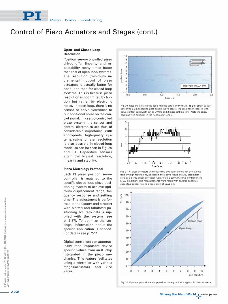
2-200
©P
hys
ikIn
stru
men
te(P
I)G
mb
H&
Co
.KG
2008
.Su
bje
ctto
chan
ge
wit
ho
ut
no
tice
.C
at12
0EIn
spir
atio
ns2
009
08/1
0.18
Piezo • Nano • Positioning
Open- and Closed-Loop
Resolution
Position servo-controlled piezodrives offer linearity and re-peatability many times betterthan that of open-loop systems.The resolution (minimum in-cremental motion) of piezoactuators is actually better foropen-loop than for closed-loopsystems. This is because piezoresolution is not limited by fric-tion but rather by electronicnoise. In open-loop, there is nosensor or servo-electronics toput additional noise on the con-trol signal. In a servo-controlledpiezo system, the sensor andcontrol electronics are thus ofconsiderable importance. Withappropriate, high-quality sys-tems, subnanometer resolutionis also possible in closed-loopmode, as can be seen in Fig. 30and 31. Capacitive sensorsattain the highest resolution,linearity and stability.
Piezo Metrology Protocol
Each PI piezo position servo-controller is matched to thespecific closed-loop piezo posi-tioning system to achieve opti-mum displacement range, fre-quency response and settlingtime. The adjustment is perfor-med at the factory and a reportwith plotted and tabulated po-sitioning accuracy data is sup-plied with the system (seep. 2-87). To optimize the set-tings, information about thespecific application is needed.For details see p. 2-11.
Digital controllers can automat-ically read important devicespecific values from an ID-chipintegrated in the piezo me-chanics. This feature facilitatesusing a controller with variousstages/actuators and viceversa.
Control of Piezo Actuators and Stages (cont.)
Fig. 30. Response of a closed-loop PI piezo actuator (P-841.10, 15 μm, strain gaugesensor) to a 3 nm peak-to-peak square-wave control input signal, measured withservo-control bandwidth set to 240 Hz and 2 msec settling time. Note the crisp,backlash-free behavior in the nanometer range
Fig. 31. PI piezo actuators with capacitive position sensors can achieve ex-tremely high resolutions, as seen in the above result of a 250 picometerstep by a S-303 phase corrector (Controller: E-509.C1A servo-controller andE-503 amplifier). The measurements were made with an ultra-sensitivecapacitive sensor having a resolution of ±0.02 nm
Fig. 32. Open-loop vs. closed-loop performance graph of a typical PI piezo actuator

2-201
Piezo • Nano • Positioning
Piezo Flexure Stages /High-Speed Scanning Systems
Nanopositioning / Piezoelectrics
Linear Actuators & Motors
Fast Steering Mirrors /Active Optics
Piezo Drivers /Servo Controllers
Piezoelectrics in Positioning
Nanometrology
Micropositioning
Linear
Vertical & Tip/Tilt
2- and 3-Axis
6-Axis
Single-Channel
Multi-Channel
Modular
Accessories
Index
Methods to Improve Piezo Dynamics
The dynamic behavior of apiezo positioning systemdepends on factors includingthe system’s resonant frequen-cy, the position sensor and thecontroller used. Simple con-troller designs limit the usableclosed-loop tracking band-width of a piezoelectric systemto 1/10 of the system’s reso-nant frequency. PI offers con-trollers that significantly in-crease piezo actuator systemdynamics (see table). Two ofthe methods are describedbelow; additional informationis available on request.
InputShaping® Stops
Structural Ringing Caused by
High-Throughput Motion
A patented, real-time, feedfor-ward technology calledInputShaping® nullifies reso-
nances both inside and outsidethe servo-loop and virtuallyeliminates the settling phase.The procedure requires deter-mination of all critical resonantfrequencies in the system. Anon-contact instrument like aPolytec Laser Doppler Vibro-meter is especially well-suitedfor such measurements. Thevalues, most importantly theresonant frequency of the sam-ple on the platform, are thenfed into the InputShaping®
Signal processor. There thesophisticated signal process-ing algorithms assure thatnone of the undesired reso-nances in the system or its aux-illary components is excited.Because the processor is out-side the servo-loop, it works inopen-loop operation as well.The result: the fastest possiblemotion, with settling within a
time equal one period of thelowest resonant frequency.InputShaping® was developedbased on research at theMassachusetts Institute ofTechnology and commercial-ized by Convolve, Inc.(www.convolve.com). It is anoption in several PI digitalpiezo controllers.
Various Methods to Improve Piezo Dynamics
Method Goals
Feedforward Reduce phase difference between output and input (tracking error)
Signal preshaping (software) Increase operating frequency of the system, correct amplitude and phaseresponse. Two learning phases required; only for periodic signals.
Adaptive preshaping (hardware) Increase operating frequency of the system, correct amplitude and phaseresponse. No learning phase, but settling phase required;only for periodic signals.
Linearization (digital, in DSP) Compensate for piezo hysteresis and creep effects
InputShaping® Cancel recoil-generated ringing, whether inside or outside theservo-loop. Reduce the settling time. Closed- and open-loop.
Dynamic Digital Linearization (DDL) Increase operating frequency of the system, correct amplitudeand phase response. Integrated in digital controller.No external metrology necessary, for periodic signals only.
Fig. 33. InputShaping® eliminates therecoil-driven resonant reaction of loadsand neighboring components due torapid nanopositioner actuation.Top: Polytec Laser Vibrometer revealsthe resonant behavior of an undampedfixture when the nanomechanism isstepped.Bottom: Same setup, same step, butwith InputShaping®. Structural ringingis eliminated. With no excitation ofvibration in the moved components,the target position is attained in a timesmaller than one period of the resonantfrequency

2-202
©P
hys
ikIn
stru
men
te(P
I)G
mb
H&
Co
.KG
2008
.Su
bje
ctto
chan
ge
wit
ho
ut
no
tice
.C
at12
0EIn
spir
atio
ns2
009
08/1
0.18
Piezo • Nano • Positioning
Fig. 34 a. Signal preshaping, phase 1
Fig. 34 b. Signal preshaping, phase 2
Signal Preshaping / Dynamic
Digital Linearization (DDL)
Signal Preshaping, a patentedtechnique, can reduce rolloff,phase error and hysteresis inapplications with repetitive(periodic) inputs. The result isto improve the effective band-width, especially for trackingapplications such as out-of-round turning of precisionmechanical or optical parts.Signal Preshaping is imple-mented in object code, basedon an analytical approach inwhich the complex transferfunction of the system is calcu-lated, then mathematicallytransformed and applied in afeedforward manner to reducethe tracking error.
Signal Preshaping is moreeffective than simple phase-shifting approaches and canimprove the effective band-width by a factor of 10 and inmulti-frequency applications.
Frequency response and har-monics (caused by nonlinearityof the piezo-effect) are deter-mined in two steps using FastFourier Transformation (FFT),and the results are used to cal-culate the new control profilefor the trajectory. The new con-trol signal compensates for thesystem non-linearities.
Methods to Improve Piezo Dynamics (cont.)
For example, it is possible toincrease the command ratefrom 20 Hz to 200 Hz for a piezosystem with a resonant fre-quency of 400 Hz without com-promising stability. At the sametime, the tracking error isreduced by a factor of about 50.
Fig. 35. No preshapingA: Control input signal (expected motion)B: Actual motion of systemC: Tracking error
Fig. 36. Signal after preshaping phase 2A: Expected Motion (old control signal)B: Actual motion of systemC: New control input (producted by preshaping)D: Tracking error

2-203
Piezo Flexure Stages /High-Speed Scanning Systems
Nanopositioning / Piezoelectrics
Linear Actuators & Motors
Fast Steering Mirrors /Active Optics
Piezo Drivers /Servo Controllers
Piezoelectrics in Positioning
Nanometrology
Micropositioning
Linear
Vertical & Tip/Tilt
2- and 3-Axis
6-Axis
Single-Channel
Multi-Channel
Modular
Accessories
Index
Piezo • Nano • Positioning
Dynamic Digital Linearization
(DDL)
DDL is similar in performanceto Input Preshaping, but is sim-pler to use. In addition, it canoptimize multi-axis motionsuch as a raster scan or tracingan ellipse. This methodrequires no external metrologyor signal processing (see p.2-108). DDL uses the positioninformation from capacitivesensors integrated in the piezomechanics (requires directmetrology) to calculate theoptimum control signal. Aswith preshaping, the result isan improvement in linearityand tracking accuracy of up to 3orders of magnitude.
Fig. 37 a. Elliptical scan in a laser micro-drilling application with XYpiezo scanning stage, conventional PID controller. The outer ellipsedescribes the target position, the inner ellipse shows the actualmotion at the stage
Fig. 37 b. Same scan as before, with a DDL controller. Targetand actual data can hardly be discerned. The tracking error hasbeen reduced to a few nanometers

2-204
©P
hys
ikIn
stru
men
te(P
I)G
mb
H&
Co
.KG
2008
.Su
bje
ctto
chan
ge
wit
ho
ut
no
tice
.C
at12
0EIn
spir
atio
ns2
009
08/1
0.18
Piezo • Nano • Positioning
Note
Closed-loop piezo positioningsystems are less sensitive totemperature changes thanopen-loop systems. Optimumaccuracy is achieved if theoperating temperature is iden-tical to the calibration tempera-ture. If not otherwise specified,PI piezomechanics are calibrat-ed at 22 °C.
Environmental Conditions and InfluencesTemperature Effects
Two effects
must be considered:
� Linear Thermal Expansion� Temperature Dependency of
the Piezo Effect
Linear Thermal Expansion
Thermal stability of piezoce-ramics is better than that ofmost other materials. Fig. 38ashows the behavior of severaltypes of piezoceramics used byPI. The curves only describethe behavior of the piezoce-ramics. Actuators and position-ing systems consist of a combi-nation of piezoceramics andother materials and their over-all behavior differs accordingly.
Temperature Dependency of
the Piezo Effect
Piezo translators work in awide temperature range. Thepiezo effect in PZT ceramics isknown to function down toalmost zero kelvin, but themagnitude of the piezo coeffi-cients is temperature depend-ent.
At liquid helium temperaturepiezo gain drops to approxi-mately 10–20 % of its room-temperature value.
Piezoceramics must be poledto exhibit the piezo effect. Apoled PZT ceramic may depolewhen heated above the maxi-mum allowable operating tem-perature. The “rate” of depol-ing is related to the Curie tem-perature of the material. PIHVPZT actuators have a Curietemperature of 350 °C and canbe operated at up to 150 °C.LVPZT actuators have a Curietemperature of 150 °C and canbe operated at up to 80 °C. Thenew monolithic PICMA® ceram-ics with their high Curie tem-perature of 320 °C allow oper-ating at temperatures of up to150 °C.
Piezo Operation
in High Humidity
The polymer insulation materi-als used in piezoceramic actua-tors are sensitive to humidity.Water molecules diffusethrough the polymer layer and
can cause short circuiting ofthe piezoelectric layers. Theinsulation materials used inpiezo actuators are sensitive tohumidity. For higher humidityenvironments, PI offers specialsystems with waterproofedenclosed stacks, or integrateddry-air flushing mechanisms.A better solution are PICMA®
actuators (see Fig. 39a), whichhave ceramic-only insulationwithout any polymer coveringand are thus less sensitive towater diffusion (see Fig. 39c).
Fig. 38 a. Linear thermal expansion of different PZT ceramics
Fig. 38 b. The expansion of PICMA® piezoceramics is only slightly tem-perature dependent. This, and their low heat generation, makes themideal for dynamic applications

2-205
Piezo • Nano • Positioning
Piezo Flexure Stages /High-Speed Scanning Systems
Nanopositioning / Piezoelectrics
Linear Actuators & Motors
Fast Steering Mirrors /Active Optics
Piezo Drivers /Servo Controllers
Piezoelectrics in Positioning
Nanometrology
Micropositioning
Linear
Vertical & Tip/Tilt
2- and 3-Axis
6-Axis
Single-Channel
Multi-Channel
Modular
Accessories
Index
Piezo Operation in Inert Gas
Atmospheres
Ceramic-insulated PICMA®
actuators are also recommend-ed for use in inert gases, suchas helium. To reduce the dan-ger of flashover with high-volt-age piezos, the maximum oper-ating voltage must be reduced.Semi-bipolar operation is rec-ommended, because the aver-age operating voltage can bekept very low.
Vacuum Operation
of Piezo Actuators
All PI piezo actuators can beoperated at pressures below100 Pa (~1 torr). When piezoactuators are used in a vacu-um, two factors must be con-sidered:
I. Dielectric stability
II. Outgassing
I. The dielectric breakdown volt-age of a sample in a specificgas is a function of the pres-sure p times the electrode dis-tance s. Air displays a highinsulation capacity at atmos-pheric pressure and at very lowpressures. The minimumbreakdown voltage of ~300 Vcan be found at a ps-product of1000 mm Pa (~10 mm torr).
That is why PICMA® actuatorswith a maximum operatingvoltage of 120 V can be used inany vacuum condition. How-ever, the operation of HVPZTactuators with dielectric layerthicknesses of 0.2 – 1.0 mm andnominal voltages to 1000 V isnot recommended in the pres-sure range of 100 – 50000 Pa(~1 – 500 torr).
II. Outgassing behavior variesfrom model to model depend-ing on design. Ultra-high-vacu-um options for minimum out-gassing are available for manystandard low-voltage and high-voltage piezo actuators. Bestsuited are PICMA® ceramics(see Fig. 39a), because theyhave no polymers and canwithstand bakeout to 150 °C(see also “Options” in the“Piezo Actuators & Components”sections, p. 2-104 ff ).
All materials used in UHV-com-patible piezo nanopositioners,including cables and connec-tors, are optimized for minimaloutgassing rates (see Fig. 39b).Materials lists are available onrequest.
Fig. 39 a. PICMA® actuators are made with ceramic-only insulation and candispense with any polymer coating. Result No measurable outgasing, insen-
sitive to atmospheric humidity and a wider operating temperature range
Fig. 39 b. P-733.UUD UHV-compatible XY stage for scanning microscopyapplications. PICMA® ceramics are used here too. All materials used are
optimized for minimal outgassing. Materials lists are available on request

2-206
©P
hys
ikIn
stru
men
te(P
I)G
mb
H&
Co
.KG
2008
.Su
bje
ctto
chan
ge
wit
ho
ut
no
tice
.C
at12
0EIn
spir
atio
ns2
009
08/1
0.18
Piezo • Nano • Positioning
The lifetime of a piezo actuatoris not limited by wear and tear.Tests have shown that PI piezoactuators can perform billions(109) of cycles without anymeasurable wear.
As with capacitors, however,the field strength does have aninfluence on lifetime. The aver-age voltage should be kept aslow as possible. Most PI piezoactuators and electronics aredesigned for semi-bipolaroperation.
There is no generic formula todetermine the lifetime of apiezo actuator because of themany parameters, such as tem-perature, humidity, voltage,acceleration, load, preload,operating frequency, insulationmaterials, etc., which have(nonlinear) influences. PI piezoactuators are not only opti-mized for maximum travel, butalso designed for maximumlifetime under actual operatingconditions.
The operating voltage rangevalues in the technical datatables are based on decades ofexperience with nanomech-anisms and piezo applicationsin industry. Longer travel canonly be obtained with highervoltages at the cost of reducedreliability.
Example:
An P-842.60 LVPZT actuator(see p. 1-76 in the “PiezoActuators & Components” sec-tion) is to operate a switch witha stroke of 100 μm. Of its oper-ating time, it is to be open for70 % and closed for 30 %.
Optimum solution: The actua-tor should be linked to theswitch in such a way that theopen position is achieved withthe lowest possible operatingvoltage. To reach a displace-ment of 100 μm, a voltage
amplitude of approximately110 volts is required (nominaldisplacement at 100 V is only90 μm).
Since the P-842.60 can be oper-ated down to -20 volts, theclosed position should beachieved with 90 V, and theopen position with -20 volts.When the switch is not in use atall, the voltage on the piezoactuator should be 0 volts.
Statistics show that most fail-ures with piezo actuators occurbecause of excessive mechani-cal stress. Particularly destruc-tive are tensile and shearforces, torque and mechanicalshock. To protect the ceramicfrom such forces PI offers avariety of actuators with pre-loads, ball tips, flexible tips aswell as custom designs.
Failures can also occur whenhumidity or conductive materi-als such as metal dust degradethe PZT ceramic insulation,leading to irreparable dielectricbreakdown. In environmentspresenting these hazards,PICMA® actuators with theirceramic-only insulation arestrongly recommended. PI alsooffers hermetically sealed actu-ators and stages.
Lifetime of Piezo Actuators
Environmental Conditions and Influences (cont.)
Fig. 39 d. P-885.50 PICMA® actuators with 15 MPa preload in dynamic motion test at116 Hz. No observable wear after 1.2 billion (109) cycles
Fig. 39 c. PICMA® piezo actuators (lower curve) compared with conventional multi-layer piezo actuators with polymer insulation. PICMA® actuators are insensitve tohigh humidity in this test. In conventional actuators, the leakage current beginsto rise after only a few hours—an indication of degradation of the insulation andreduced lifetime.Test conditions: U = 100 VDC, T = 25 °C, RH = 70%

2-207
Piezo • Nano • Positioning
Piezo Flexure Stages /High-Speed Scanning Systems
Nanopositioning / Piezoelectrics
Linear Actuators & Motors
Fast Steering Mirrors /Active Optics
Piezo Drivers /Servo Controllers
Piezoelectrics in Positioning
Nanometrology
Micropositioning
Linear
Vertical & Tip/Tilt
2- and 3-Axis
6-Axis
Single-Channel
Multi-Channel
Modular
Accessories
Index
Basic Designs of Piezoelectric Positioning Drives/Systems
Stack Design (Translators)
The active part of the position-ing element consists of a stackof ceramic disks separated bythin metallic electrodes. Themaximum operating voltage isproportional to the thickness ofthe disks. Most high-voltageactuators consist of ceramiclayers measuring 0.4 to 1 mmin thickness. In low-voltagestack actuators, the layers arefrom 25 to 100 μm in thicknessand are cofired with the elec-trodes to form a monolithicunit.
Stack elements can withstandhigh pressures and exhibit thehighest stiffness of all piezoactuator designs. Standarddesigns which can withstandpressures of up to 100 kN areavailable, and preloaded actua-tors can also be operated inpush-pull mode. For furtherinformation see “MaximumApplicable Forces”, p. 2-189.
Displacement of a piezo stackactuator can be estimated bythe following equation:
(Equation 24)
where:
�L = displacement [m]
d33 = strain coefficient (fieldand displacement inpolarization direction)[m/V]
n = number of ceramic layers
U = operating voltage [V]
Example:
P-845, p. 1-76, etc. (see the“Piezo Actuators & Components”section)
Laminar Design
(Contraction-Type Actuators)
The active material in the lami-nar actuators consists of thin,laminated ceramic strips. Thedisplacement exploited inthese devices is that perpendi-cular to the direction of polar-ization and electric field appli-cation. When the voltage isincreased, the strip contracts.The piezo strain coefficient d31(negative!) describes the rela-tive change in length. Itsabsolute value is on the orderof 50 % of d33.
The maximum travel is a func-tion of the length of the strips,while the number of stripsarranged in parallel determinesthe stiffness and force genera-tion of the element.
Displacement of a piezo con-traction actuator can be esti-mated by the following equa-tion:
(Equation 25)
where:
�L = displacement [m]
d31 = strain coefficient(displacement normalto polarization direction)[m/V]
L = length of the piezoce-ramics in the electricfield direction [m]
U = operating voltage [V]
d = thickness of one ceramiclayer [m]
Fig. 41. Mechanical design of a stack translator
Fig. 40. Electrical design of a stack translator
Fig. 42. Laminar actuator design

2-208
©P
hys
ikIn
stru
men
te(P
I)G
mb
H&
Co
.KG
2008
.Su
bje
ctto
chan
ge
wit
ho
ut
no
tice
.C
at12
0EIn
spir
atio
ns2
009
08/1
0.18
Piezo • Nano • Positioning
Fig. 44. Piezo scanner tube working principle
Tube Design
Monolithic ceramic tubes areyet another form of piezo actu-ator. Tubes are silvered insideand out and operate on thetransversal piezo effect. Whenan electric voltage is appliedbetween the outer and innerdiameter of a thin-walled tube,the tube contracts axially andradially. Axial contraction canbe estimated by the followingequation:
(Equation 26 a)
where:
d31 = strain coefficient (dis-placement normal topolarization direction)[m/V]
L = length of the piezoceramic tube [m]
U = operating voltage [V]
d = wall thickness [m]
The radial displacement is theresult of the superposition ofincrease in wall thickness(Equation 26 b) and the tangen-tial contraction:
(Equation 26 b)
r = tube radius
(Equation 26 c)
where:
�d = change in wall thickness[m]
d33 = strain coefficient (fieldand displacement inpolarization direction)[m/V]
U = operating voltage [V]
When the outside electrode ofa tube is separated into four90° segments, placing differen-tial drive voltages ±U onopposing electrodes will leadto bending of one end. Suchscanner tubes that flex in X andY are widely used in scanning-probe microscopes, such asscanning tunneling micro-scopes.
The scanning range can beestimated as follows:
(Equation 27)
where:
�x = scan range in X and Y(for symmetrical electro-des) [m]
d31 = strain coefficient (dis-placement normal topolarization direction)[m/V]
U = differential operatingvoltage [V]
L = length [m]
ID = inside diameter [m]
d = wall thickness [m]
Tube actuators cannot gener-ate or withstand large forces.Application examples: Micro-dosing, nanoliter pumping,scanning microscopy, ink jetprinters.
Examples:
PT120, PT130, PT140 (p. 1-100).
Fig. 43. Tube actuator design
Basic Designs of Piezoelectric Positioning Drives/Systems (cont.)
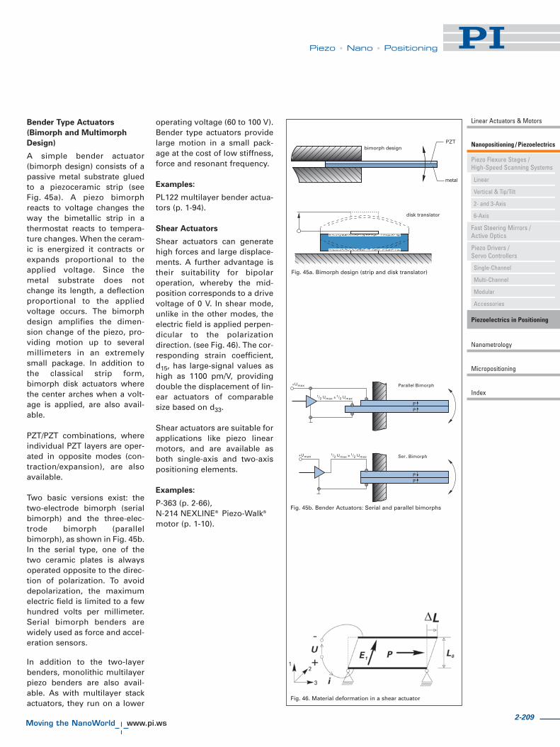
2-209
Piezo • Nano • Positioning
Bender Type Actuators
(Bimorph and Multimorph
Design)
A simple bender actuator(bimorph design) consists of apassive metal substrate gluedto a piezoceramic strip (seeFig. 45a). A piezo bimorphreacts to voltage changes theway the bimetallic strip in athermostat reacts to tempera-ture changes. When the ceram-ic is energized it contracts orexpands proportional to theapplied voltage. Since themetal substrate does notchange its length, a deflectionproportional to the appliedvoltage occurs. The bimorphdesign amplifies the dimen-sion change of the piezo, pro-viding motion up to severalmillimeters in an extremelysmall package. In addition tothe classical strip form,bimorph disk actuators wherethe center arches when a volt-age is applied, are also avail-able.
PZT/PZT combinations, whereindividual PZT layers are oper-ated in opposite modes (con-traction/expansion), are alsoavailable.
Two basic versions exist: thetwo-electrode bimorph (serialbimorph) and the three-elec-trode bimorph (parallelbimorph), as shown in Fig. 45b.In the serial type, one of thetwo ceramic plates is alwaysoperated opposite to the direc-tion of polarization. To avoiddepolarization, the maximumelectric field is limited to a fewhundred volts per millimeter.Serial bimorph benders arewidely used as force and accel-eration sensors.
In addition to the two-layerbenders, monolithic multilayerpiezo benders are also avail-able. As with multilayer stackactuators, they run on a lower
operating voltage (60 to 100 V).Bender type actuators providelarge motion in a small pack-age at the cost of low stiffness,force and resonant frequency.
Examples:
PL122 multilayer bender actua-tors (p. 1-94).
Shear Actuators
Shear actuators can generatehigh forces and large displace-ments. A further advantage istheir suitability for bipolaroperation, whereby the mid-position corresponds to a drivevoltage of 0 V. In shear mode,unlike in the other modes, theelectric field is applied perpen-dicular to the polarizationdirection. (see Fig. 46). The cor-responding strain coefficient,d15, has large-signal values ashigh as 1100 pm/V, providingdouble the displacement of lin-ear actuators of comparablesize based on d33.
Shear actuators are suitable forapplications like piezo linearmotors, and are available asboth single-axis and two-axispositioning elements.
Examples:
P-363 (p. 2-66),N-214 NEXLINE® Piezo-Walk®
motor (p. 1-10).
Fig. 45a. Bimorph design (strip and disk translator)
Fig. 45b. Bender Actuators: Serial and parallel bimorphs
Fig. 46. Material deformation in a shear actuator
metal
.
Piezo Flexure Stages /High-Speed Scanning Systems
Nanopositioning / Piezoelectrics
Linear Actuators & Motors
Fast Steering Mirrors /Active Optics
Piezo Drivers /Servo Controllers
Piezoelectrics in Positioning
Nanometrology
Micropositioning
Linear
Vertical & Tip/Tilt
2- and 3-Axis
6-Axis
Single-Channel
Multi-Channel
Modular
Accessories
Index

2-210
©P
hys
ikIn
stru
men
te(P
I)G
mb
H&
Co
.KG
2008
.Su
bje
ctto
chan
ge
wit
ho
ut
no
tice
.C
at12
0EIn
spir
atio
ns2
009
08/1
0.18
Piezo • Nano • Positioning
Piezo Actuators with
Integrated Lever Motion
Amplifiers
Piezo actuators or positioningstages can be designed in sucha way that a lever motionamplifier is integrated into thesystem. To maintain sub-nanometer resolution with theincreased travel range, thelever system must be extreme-ly stiff, backlash- and friction-free, which means ball or rollerbearings cannot be used.Flexures are ideally suited aslinkage elements. Using flex-ures, it is also possibleto design multi-axis position-ing systems with excellentguidance characteristics (seep. 2-211).
PI employs finite elementanalysis (FEA) computer simu-lation to optimize flexurenanopositioners for the bestpossible straightness and flat-ness (see Fig. 49 and Fig. 51).
Piezo positioners with integrat-ed motion amplifiers have bothadvantages and disadvantagescompared to standard piezoactuators:
Advantages:
� Longer travel� Compact size compared to
stack actuators with equaldisplacement
� Reduced capacitance(= reduced drive current)
Disadvantages:
� Reduced stiffness� Lower resonant frequency
The following relations applyto (ideal) levers used to amplifymotion of any primary drivesystem:
where:
r = lever transmissionratio
�L0 = travel of the primarydrive [m]
�LSys = travel of the lever-amplified system [m]
ksys = stiffness of the lever-amplified system[N/m]
k0 = stiffness of the pri-mary drive system(piezo stack andjoints) [N/m]
fres-sys = resonant frequency ofthe amplified system[Hz]
fres-0 = resonant frequency ofthe primary drive sys-tem (piezo stack andjoints) [Hz]
Note:
The above equations are basedon an ideal lever design withinfinite stiffness and zero mass.They also imply that no stiff-ness is lost at the couplinginterface between the piezostack and the lever. In realapplications, the design of agood lever requires long expe-
rience in micromechanics andnanomechanisms. A balancebetween mass, stiffness andcost must be found, whilemaintaining zero-friction andzero-backlash conditions.
Coupling the piezo stack to thelever system is crucial. Thecoupling must be very stiff inthe pushing direction butshould be soft in all otherdegrees of freedom to avoiddamage to the ceramics. Evenif the stiffness of each of thetwo interfaces is as high as thatof the piezo stack alone, a 67 %loss of overall stiffness stillresults. In many piezo-drivensystems, the piezo stiffness isthus not the limiting factor indetermining the stiffness of themechanism as a whole.
PI piezomechanics are opti-mized in this regard as a resultof more than 30 years experi-ence with micromechanics,nanopositioning and flexures.
Basic Designs of Piezoelectric Positioning Drives/Systems (cont.)
Fig. 47. Simple lever motion amplifier

2-211
Piezo • Nano • Positioning
Piezo Flexure Stages /High-Speed Scanning Systems
Nanopositioning / Piezoelectrics
Linear Actuators & Motors
Fast Steering Mirrors /Active Optics
Piezo Drivers /Servo Controllers
Piezoelectrics in Positioning
Nanometrology
Micropositioning
Linear
Vertical & Tip/Tilt
2- and 3-Axis
6-Axis
Single-Channel
Multi-Channel
Modular
Accessories
Index
Piezo Flexure Nanopositioners
For applications whereextremely straight motion inone or more axes is neededand only nanometer or micro-rad deviation from the idealtrajectory can be tolerated,flexures provide an excellentsolution.
A flexure is a frictionless, stic-tionless device based on theelastic deformation (flexing) ofa solid material (e.g. steel).Sliding and rolling are entirelyeliminated. In addition, flexuredevices can be designed withhigh stiffness, high load capac-ity and do not wear. They arealso less sensitive to shock andvibration than other guidingsystems. They are also mainte-nance-free, can be fabricatedfrom non-magnetic materials,require no lubricants or con-sumables and hence, unlike aircushion bearings, are suitablefor vacuum operation.
Parallelogram flexures exhibitexcellent guidance characteris-tics. Depending on complexityand tolerances, they havestraightness/flatness values inthe nanometer range or better.Basic parallelogram flexurescause arcuate motion (travel inan arc) which introduces anout-of-plane error of about0.1% of the travel range (seeFig. 48). The error can be esti-mated by the following equa-tion:
(Equation 28)
where:
�H = out-of-plane error [m]
�L = distance traveled [m]
H = length of flexures [m]
For applications where thiserror is intolerable, PI hasdesigned a zero-arcuate-errormulti-flexure guiding system.This special design, employedin most PI flexure stages,makes possible straightness/flatness in the nanometeror microradian range (seeFig. 49).
Note:
Flexure positioners are farsuperior to traditional position-ers (ball bearings, crossedroller bearings, etc.) in terms ofresolution, straightness andflatness. Inherent friction andstiction in these traditionaldesigns limit applications tothose with repeatability re-quirements on the order of 0.5to 0.1 μm. Piezo flexurenanopositioning systems haveresolutions and repeatabilitieswhich are superior by severalorders of magnitude.
Fig. 48. Basic parallelogram flexure guiding system with motion ampli-fication. The amplification r (transmission ratio) is given by (a+b)/a
Fig. 49. Zero-arcuate-error multi-flexure guiding system

2-212
©P
hys
ikIn
stru
men
te(P
I)G
mb
H&
Co
.KG
2008
.Su
bje
ctto
chan
ge
wit
ho
ut
no
tice
.C
at12
0EIn
spir
atio
ns2
009
08/1
0.18
Piezo • Nano • Positioning
Parallel and Serial Kinematics / Metrology
Direct and Indirect Metrology
Non-contact sensors are usedto obtain the most accurateposition values possible forposition servo-control systems.Two-plate capacitive sensorsinstalled directly on the movingplatform and measuring on theaxis of motion offer the bestperformance. Resolution andrepeatability can attain 0.1nanometer in such systems.Indirect metrology—measuringstrain at some point in the drivetrain—cannot be used in sys-tems with the highest accuracyrequirements.
Fig. 50 b. Working principle of a nested XY piezo stage (serial kinematics).Lower center of gravity and somewhat better dynamics compared withstacked system, but retains all the other disadvantages of a stacked system,including asymmetric dynamic behavior of X and Y axes
Fig. 50 c. Working principle of a monolithic XY�Z parallel kinematics piezo stage. Allactuators act directly on the central platform. Integrated parallel metrology keeps allmotion in all controlled degrees of freedom inside the servo-loop. The position of thecentral, moving platform is measured directly with capacitive sensors, permitting alldeviations from the prescribed trajectory to be corrected in real-time. This feature,called active trajectory control, is not possible with serial metrology
Fig. 50 a. Working principle of a stacked XY piezo stage (serial kinematics).Advantages: Modular, simple design. Disadvantages compared with parallelkinematics: More inertia, higher center of gravity, moving cables (can causefriction and hysteresis). Integrated parallel metrology and active trajectorycontrol (automatic off-axis error correction) are not possible

2-213
Piezo • Nano • Positioning
Piezo Flexure Stages /High-Speed Scanning Systems
Nanopositioning / Piezoelectrics
Linear Actuators & Motors
Fast Steering Mirrors /Active Optics
Piezo Drivers /Servo Controllers
Piezoelectrics in Positioning
Nanometrology
Micropositioning
Linear
Vertical & Tip/Tilt
2- and 3-Axis
6-Axis
Single-Channel
Multi-Channel
Modular
Accessories
Index
Parallel and
Serial Kinematics
There are two basic ways todesign multi-axis positioningsystems: Serial kinematics andparallel kinematics. Serial kine-matics are easier to design andbuild and can be operated withsimpler controllers. They do,however, have a number of dis-advantages compared to high-er-performance and more ele-gant parallel kinematics sys-tems. In a multi-axis serial kine-matics system, each actuator isassigned to exactly one degreeof freedom. If there are inte-grated position sensors, theyare also each assigned to onedrive and measure only themotion caused by that driveand in its direction of motion.All undesired motion (guidingerror) in the other five degreesof freedom are not seen andhence cannot be corrected inthe servo-loop, which leads tocumulative error.
In a parallel kinematics multi-axis system, all actuators actdirectly on the same movingplatform.
Only in this way can the sameresonant frequency anddynamic behavior be obtainedfor the X and Y axes. It is alsoeasy to implement parallelmetrology in parallel kinemat-ics systems. A parallel metrolo-gy sensor sees all motion in itsmeasurement direction, notjust that of one actuator, sorunout from all actuators canbe compensated in real-time(active trajectory control). Theresults are significantly lessdeviation from the ideal trajec-tory, better repeatability andflatness, as shown in Fig. 51.
Examples:
P-734, P-561 (p. 2-64, p. 2-72) .in the “Piezo Flexure Stages /High-Speed Scanning Systems”section.
Fig. 51. Flatness (Z-axis) of a 6-axis nanopositioning system with active trajectorycontrol over a 100 x 100 μm scanning range. The moving portion of this parallelmetrology positioner is equipped with ultra-precise parallel metrology capacitivesensors in all six degrees of freedom. The sensors are continually measuring theactual position against the stationary external reference.
A digital controller compares the six coordinates of the actual position with therespective target positions. In addition to controlling the scanning motion in theX and Y directions, the controller also ensures that any deviations that occur inthe other four degrees of freedom are corrected in real-time

2-214
©P
hys
ikIn
stru
men
te(P
I)G
mb
H&
Co
.KG
2008
.Su
bje
ctto
chan
ge
wit
ho
ut
no
tice
.C
at12
0EIn
spir
atio
ns2
009
08/1
0.18
Piezo • Nano • Positioning
PMN Compared to PZT
Electrostrictive Actuators
(PMN)
Electrostrictive actuators oper-ate on a principle similar to thatof PZT actuators. The elec-trostrictive effect can beobserved in all dielectric mate-rials, even in liquids.
Electrostrictive actuators aremade of an unpolarized leadmagnesium niobate (PMN)ceramic material. PMN is aceramic exhibiting displace-ment proportional to thesquare of the applied voltageunder small-signal conditions.Under these conditions PMNunit cells are centro-symmetricat zero volts. An electrical fieldseparates the positively andnegatively charged ions,changing the dimensions of thecell and resulting in an expan-sion. Electrostrictive actuatorsmust be operated above theCurie temperature, which istypically very low when com-pared to PZT materials.
The quadratic relationshipbetween drive voltage and dis-placement means that PMNactuator are intrinsically non-linear, in contrast to PZT actua-tors. PMN actuators have anelectrical capacitance severaltimes as high as piezo actua-tors and hence require higherdrive currents for dynamicapplications. However, in a lim-ited temperature range, elec-trostrictive actuators exhibitless hysteresis (on the order of3 %) than piezo actuators. Anadditional advantage is theirgreater ability to withstandpulling forces.
PZT materials have greatertemperature stability than elec-trostrictive materials, especial-ly with temperature variationsof over 10 °C.As temperature increases,available travel is reduced; atlow temperatures where travel
is greatest hysteresis increases(see Fig. 53 b). PMN actuatorsare thus best for applicationswith little or no temperaturevariations of the ceramic, bethey caused by dynamic opera-tion or by environmental fac-tors.
PMN
PZT
V
L
Fig. 52. Comparison of PMN and PZT material: displacementas a function of field strength (generalized)
16
PMN
L
Fig. 53 a. Comparison of PMN and PZT material: displacementas a function of temperature
Fig. 53 b. Comparison of PMN and PZT material: hysteresis as afunction of temperature
PMN

2-215
Piezo • Nano • Positioning
Piezo Flexure Stages /High-Speed Scanning Systems
Nanopositioning / Piezoelectrics
Linear Actuators & Motors
Fast Steering Mirrors /Active Optics
Piezo Drivers /Servo Controllers
Piezoelectrics in Positioning
Nanometrology
Micropositioning
Linear
Vertical & Tip/Tilt
2- and 3-Axis
6-Axis
Single-Channel
Multi-Channel
Modular
Accessories
Index
Summary
Piezoelectric actuators offer asolution to many positioningtasks that depend on highestaccuracy, speed and resolution.
Examples given in this tutorialindicate a selection of themany applications commontoday. The relentless push formore accuracy and speed—whether in the further miniatur-ization of microelectronics,production of optics and high-er-performance data storagedevices, precise positioning ofoptical fiber components fortelecommunications, or in thefabrication of micromech-
anisms—drives both the appli-cation and the further develop-ment of piezo technology.To use the advantages of piezopositioners to their full extent,it is important to carefully ana-lyze the system in which apiezo actuator is used as awhole. Close contact betweenuser and manufacturer is thebest recipe for success.
Piezoelectric actuators will inthe future partially replace, par-tially complement, convention-al drive technologies. They willwiden the realm of the possi-ble, and will usher in develop-
ments in areas like nanotech-nology which would beunthinkable with conventionaldrive technologies.
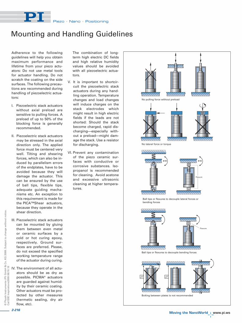
©P
hys
ikIn
stru
men
te(P
I)G
mb
H&
Co
.KG
2008
.Su
bje
ctto
chan
ge
wit
ho
ut
no
tice
.C
at12
0EIn
spir
atio
ns2
009
08/1
0.18
Piezo • Nano • Positioning
Adherence to the followingguidelines will help you obtainmaximum performance andlifetime from your piezo actu-ators: Do not use metal toolsfor actuator handling. Do notscratch the coating on the sidesurfaces. The following precau-tions are recommended duringhandling of piezoelectric actua-tors:
I. Piezoelectric stack actuatorswithout axial preload aresensitive to pulling forces. Apreload of up to 50% of theblocking force is generallyrecommended.
II. Piezoelectric stack actuatorsmay be stressed in the axialdirection only. The appliedforce must be centered verywell. Tilting and shearingforces, which can also be in-duced by parallelism errorsof the endplates, have to beavoided because they willdamage the actuator. Thiscan be ensured by the useof ball tips, flexible tips,adequate guiding mecha-nisms etc. An exception tothis requirement is made forthe PICA™Shear actuators,because they operate in theshear direction.
III. Piezoelectric stack actuatorscan be mounted by gluingthem between even metalor ceramic surfaces by acold or hot curing epoxy,respectively. Ground sur-faces are preferred. Please,do not exceed the specifiedworking temperature rangeof the actuator during curing.
IV. The environment of all actu-ators should be as dry aspossible. PICMA® actuatorsare guarded against humid-ity by their ceramic coating.Other actuators must be pro-tected by other measures(hermetic sealing, dry airflow, etc).
The combination of long-term high electric DC fieldsand high relative humidityvalues should be avoidedwith all piezoelectric actua-tors.
V. It is important to shortcir-cuit the piezoelectric stackactuators during any hand-ling operation. Temperaturechanges and load changeswill induce charges on thestack electrodes whichmight result in high electricfields if the leads are notshorted: Should the stackbecome charged, rapid dis-charging—especially with-out a preload—might dam-age the stack. Use a resistorfor discharging.
VI. Prevent any contaminationof the piezo ceramic sur-faces with conductive orcorrosive substances. Iso-propanol is recommendedfor cleaning. Avoid acetoneand excessive ultrasoniccleaning at higher tempera-tures.
No pulling force without preload
No lateral force or torque
Ball tips or flexures to decouple lateral forces orbending forces
Ball tips or flexures to decouple bending forces
Bolting between plates is not recommended
Mounting and Handling Guidelines
2-216

2-217
Piezo • Nano • Positioning
Piezo Flexure Stages /High-Speed Scanning Systems
Nanopositioning / Piezoelectrics
Linear Actuators & Motors
Fast Steering Mirrors /Active Optics
Piezo Drivers /Servo Controllers
Piezoelectrics in Positioning
Nanometrology
Micropositioning
Linear
Vertical & Tip/Tilt
2- and 3-Axis
6-Axis
Single-Channel
Multi-Channel
Modular
Accessories
Index
Symbols and Units
A Surface area [m2] (meter2)
� Coefficient of Thermal Expansion (CTE) [K-1] (1 / kelvin)
C Capacitance (F) [As/V]
dij Piezo modulus (tensor components) [m/V] (meter/volt)
ds Distance, thickness [m] (meter)
� Dielectric constant [As/Vm](ampere · second / volt · meter)
E Electric field strength [V/m] (volt/meter)
f Operating frequency [Hz] (hertz = 1/second)
F Force [N] (newton)
f0 Unloaded resonant frequency [Hz] (hertz = 1/second)
g Acceleration due to gravity: 9.81 m/s2 (meter/second2)
i Current [A] (ampere)
kS Stiffness of restraint (load) [N/m] (newton/meter)
kT Stiffness of piezo actuators [N/m] (newton/meter)
L0 Length of non-energized actuator [m] (meter)
�L Change in length (displacement) [m] (meter)
�L0 Nominal displacement with zero applied force, [m] (meter)
�Lt=0.1 Displacement at time t = 0.1 sec after voltage change, [m] (meter)
m Mass [kg] (kilogram)
P Power [W] (watt)
Q Charge [C] (coulomb = ampere x second)
S Strain [�L/L] (dimensionless)
t Time [s] (second)
TC Curie temperature [° C]
U Voltage [V] (volt)
Up-p Peak-to-peak voltage [V] (volt)


![IEEE/ASME TRANSACTIONS ON MECHATRONICS, VOL. 19, NO. 3 ... stage nanopositioning for high... · relies on nanopositioning is scanning probe microscopy ... [15], signal transformation](https://img.dokumen.tips/doc/110x75/5b6e5dbe7f8b9a180d8e8a82/ieeeasme-transactions-on-mechatronics-vol-19-no-3-stage-nanopositioning.jpg)