Embed Size (px)
Citation preview

Chapter 0
Nanoindentation of Human Trabecular Bone –Tissue Mechanical Properties Compared toStandard Engineering Test Methods
Ondrej Jiroušek
Additional information is available at the end of the chapter
http://dx.doi.org/10.5772/50152
1. Introduction
There are generally two types of bone tissue: trabecular and cortical. Cortical bone is the moredense tissue found on the surface of bones and trabecular bone is a highly porous structurethat fills the proximal and distal ends of all long bones (e.g. femur or tibia) and is also presentas a filler in other bones (e.g. in vertebral bodies). While at the molecular level both the corticaland trabecular bone are made of the same constituents, their overall mechanical properties arequite different.
Material properties of trabecular bone bone are influenced not only by the architecture andconnectivity of individual trabeculae, but also by the properties at the molecular level. Atthis level one can consider bone to be a composite mineral consisting of organic and inorganicconstituents. To relate the overall mechanical properties (strength, stiffness, yield properties)to its microstructure, it is necessary to measure the properties of individual trabeculae. Onehas to bear in mind the very small dimensions of single trabecula. Although the trabecularmicrostructure is dependent on the anatomical site, the typical length of trabecula is 1-2 mmwith diameter around 100 microns. This makes assessment of mechanical properties at thelevel of single trabeculae quite a challenging task.
To measure the mechanical properties of trabecular bone at the tissue level (at the level ofindividual trabeculae) five main methods has been designed and used: (i) tensile or three-(four-) point bending tests, (ii) buckling studies, (iii) acoustic methods, (iv) back-calculationfrom finite element simulations, (v) nanoindentation. There is a significant scatter in thematerial properties obtained by any of these methods, even when the same method is usedby different authors. The published mechanical properties of human trabecular bone varybetween 1 GPa and 15 GPa. The cause of this broad discrepancy in results might be in samplepreparation, different testing protocols or anisotropy and asymmetry of the micro-samples. Inthis chapter, two most favorite methods (nanoindentation and micromechanical testing) willbe compared.
©2012 Jiroušek, licensee InTech. This is an open access chapter distributed under the terms of theCreative Commons Attribution License (http://creativecommons.org/licenses/by/3.0),which permitsunrestricted use, distribution, and reproduction in any medium, provided the original work is properlycited.
Chapter 11

2 Will-be-set-by-IN-TECH
2. Composition and structure of bone
At the molecular level, bone is a composite material made of collagen matrix stiffened bycrystalline salts composed primarily of calcium and phosphate. Collagen is a fibrous proteinfound in flesh and connective tissues. It is a soft organic material and the main structuralprotein in the human body. The collagen provides the bone with toughness, while therigidity and stiffness of the bone is provided by inorganic salts. Apart from collagen, otherproteins are present in the bone. These include glycoproteins and protein-polysacharides(“proteoglycans”) which create an amorphous mixture of extracellular material.
These proteins comprise about 30–50% of the bone volume. In addition to this proteinconstituent of bone, there is the inorganic constituent – a mineral very similar tohydroxyapatite, which is a naturally occurring mineral form of calcium apatite and canbe described chemically as Ca10(PO4)6(OH)2. Hydroxyapatite in bone includes calciumphosphate, calcium carbonate, calcium fluoride, calcium hydroxide and citrate. In bone, themineral is present in form of crystals with the shape of plates or rods, with thickness about 8to 15 Å, width 20 to 40 Å and length 200 to 400 Å.
To summarize, on molecular level bone is a hard or mineralized or calcified tissue, consistingfrom organic matrix impregnated with the inorganic bone mineral. About 70% of the boneweight is given by the inorganic mineral. Generally, bone mineral shows positive correlationwith bone strength, however, in metabolic diseases, such osteoporosis it fails to predict thebone strength correctly because these metabolic disorder results in weaker bones in presenceof greater mineral density.
Going from the molecular level up, one can see that the collagen molecules and crystals ofhydroxyapatite are assembled into microfibrils. These fibrils are again assembled into fiberswith thickness about 3 to 5 μm. This level is often called ultrastructural level. The next levelis important from the material properties point of view. In this level, the fibers are assembledeither randomly into woven bone or are organized into lamellae forming lamellar bone. Theselamellae can be either in concentric groups, called osteons or can form linear lammelar groups,called plexiform bone. This level is called microstructural level.
At the same level, the bone is different not only in terms of lamellar organization, but also interms of its architectural organization. There are two types of architectural structure presentin all types of bones. On the surface of the bones, there is a thin layer of dense bone, calledcortical or compact bone. Under this dense layer the ends of all weight-bearing bones are filledwith less dense type of bone, called trabecular or spongional bone (see Fig. 1). The primaryfunction of the cortical bone is to support the whole body, to provide for the movement andto protect the soft inner organs. Secondary function of the cortical bone is to store and releasecalcium.
The trabecular bone gives supporting strength to the ends of long bones, vertebral bodiesand other bones providing structural support and flexibility. The inner structure of trabecularbone is a result of structural optimization provided by remodeling processes. Result of theseprocesses is a strong, but lightweight structure with superior mechanical properties withoutthe weight of compact bone.
From the above mentioned arises the importance of the bone composition and structure atmolecular, ultrastructural and microstructural levels for the resulting mechanical properties
260 Nanoindentation in Materials Science

Nanoindentation of Human Trabecular Bone – Tissue Mechanical Properties Compared to Standard Engineering Test Methods 3
Haversian canal
Volkmann's canal
Interstitial lamelae
Outer circumferential lamelae
Osteon
Trabeculae
Inner circumferential lamelae
Osteocytes in lacunae
Figure 1. A schematic picture of bone structure showing trabecular, lamellar and cortical bone.Interstitial and circumferential (inner and outer) lamelae are distinguished.
compact bone
trabecular bone
Figure 2. Longitudinal cut through proximal part of human femur. Red arrows indicate the thickness ofcortical bone layer.
of both cortical and trabecular bone. And because in the living organism the skeleton is ametabolically active organ undergoing continuous remodeling process one has to distinguishbetween the newly deposited bone and fully calcified (old) bone. Bone remodeling is a lifelongprocess composed of resorption (old bone tissue removal) and formation (aposition of newbone). For the trabecular bone, most of the remodeling process takes place on the surfaceof the trabecular structure, the interstitial bone (bone tissue in the middle part of trabeculae)is often excluded from remodeling [1, 2]. This phenomenon has a consequence in highlynonuniform distribution of mineral content [3]. In the new bone tissue, most of the mineral isdeposited in a couple of days (approximately 70%), then the process slows down dramaticallyand the remaining mineral is deposited in the following years [4]. Thus, the interstitial bonehas a larger mineral content compared to the bone on the surface.
261Nanoindentation of Human Trabecular Bone –
Tissue Mechanical Properties Compared to Standard Engineering Test Methods

4 Will-be-set-by-IN-TECH
Figure 3. Trabecular bone as seen in scanning electron microscope (SEM). Sample of healthy bone fromhuman proximal femur. The dark dots in the enlarged image are lacunae that contain osteocytes (mostnumerous bone cell).
2.1. Bone quality assessment
Traditionally, bone quality is described by bone mass or Bone Mineral Density (BMD)measured by dual energy X-ray absorptiometry (DXA, previously DEXA) [5], [6]. Today,BMD is used as a predictor of fracture risk in both healthy and osteoporotic bone. In DXAmeasurements, two X-ray beams with different energy levels are used and the absorption ofX-rays by the tissues is measured. The two distinct energy levels allows to differentiate thebone tissue from the soft tissues (one X-ray beam is absorbed mainly by the soft tissues). TheBMD is evaluated after the X-ray absorption by the soft tissues is eliminated.
One of the reasons for DXA failing to assess the risk of osteoporotic fracture properly [7] isthe fact that bone mechanical properties correlate not only to the bone mineral density, butmore importantly to its three-dimensional inner structure [8, 9]. Moreover, recent studies, e.g.[10] show the inability of DXA to account for the large variability in skeletal size and bodycomposition in growing children.
Proper, precise and reliable assessment of morphometric and mechanical properties oftrabecular bone have both biological and clinical importance. Fracture risk assessment at earlytime is essential for better treatment of bone diseases such as osteoporosis. To improve thereliability of fracture risk assessment, it is necessary to improve the diagnostic possibilitiesof modern imaging systems, such as microfocus computed tomography (micro-CT) orhigh-resolution peripheral quantitative computed tomography (HR-pQCT) for assessment ofthe 3D microstructure of cortical and trabecular bone in vivo and to improve measurementtechniques to assess the material properties of trabecular (and cortical) bone at themicrostructural level.
2.2. Measurement of bone mechanical properties
Mechanical properties of engineering materials are usually measured experimentally byperforming mechanical tests. For engineering materials a sample of the material of knowndimensions is prepared and exposed to mechanical load to measure its strength, elasticconstants or other material properties under various loading and environmental conditions.For engineering materials there is a set of standardized test methods such as those developedby the American Society for Testing and Materials (ASTM) and the International Organization
262 Nanoindentation in Materials Science

Nanoindentation of Human Trabecular Bone – Tissue Mechanical Properties Compared to Standard Engineering Test Methods 5
for Standardization (ISO). However, testing of biological materials is more complicated –often it is not possible to prepare a sample with specific dimensions and, more importantly,because the capability of the tissue to retain its natural material properties ex vivo is limited,environmental conditions, namely temperature and hydration must be considered during thetests.
Most of the tissues exhibit viscoelastic or viscoplastic behavior. This is highlighted in softtissues, such as ligaments and tendons, but to some extent it is characteristic for all tissues.Mechanical properties of trabecular bone are inhomogeneous or site-specific, i.e. they dependon position in the material [11]. Moreover, they are dependent on anatomic location [12], e.g.Young’s modulus of trabecular bone from femoral head is different from vertebral body. Theyare non-linearly viscoelastic [13] and display anisotropic behavior, which is usually describedas orthotropic [14]. The orthotropic behavior of trabecular bone is given by the microstructuralarrangement of the trabecular network; at the level of single trabecula the properties canbe considered isotropic. The only study that studies the anisotropy in elastic properties oftrabecular bone is [15] in which the authors used microindentation with depth equal to 2.5 μmin six different regions of interest – three on axial and three on transverse sections throughtrabeculae. In axial direction the bone exhibit significantly higher indentation modulus thanin transverse direction, suggesting the transverse anisotropy for vertebral trabecular bone.However, there is no other study proving the anisotropy of indentation modulus for trabecularbone. This is in contrary to the compact bone where the anisotropy is present at different levelof detail, i.e. single osteon is anisotropic [16] with a higher stiffness value aligned along theaxial direction.
As already mentioned, experimental conditions, especially temperature and water contentare influencing the results of bone mechanical testing [17]. Generally, bone stiffness increasesslightly with decreasing temperature. Higher temperature has a consequence in collagendenaturation which leads to a significant decrease in the toughness of bone, but the effecton the stiffness of bone is low [18]. Effects of hydration were studied both at the microlevel,for instance in [19] nanoindentation creep tests were used for quantification of elastic andviscoelastic properties as a function of water content, or at the macrolevel, e.g. in [20] theauthors studied the effect of dehydration and rehydration on the flexural properties of wholebones (mouse femora). Generally speaking, hydration increase is associated with significant(up to ∼40%) decrease in bone stiffness [21] and elastic properties are regained at differentrates. The change in bone properties due to the dehydration can be overcome by somemethods that are able to prevent the loss of hydration. Usually, the samples are testedin a phosphate-buffered saline (PBS) bath or the PBS is dripped on its surface during theexperiment.
From the aforementioned complexity of material properties of trabecular bone it is evidentthat great care must be paid to proper sample preparation, handling during the experimentand keeping stable environmental conditions. There is a great potential of incorrectnessin existing testing procedures and one must be aware of all possible error sources. Bothmethods, that will be discussed – nanoindentation and micromechanical testing – have theiradvantages and disadvantages. While micromechanical tests are more straightforward, thesample extraction, handling and measurement of the deformation is very demanding. On theother hand, nanoindentaion of a block of trabecular bone has its own limitations, not only dueto difficulties in preserving the bone natural properties, but due to other effects which will bedescribed in the following section.
263Nanoindentation of Human Trabecular Bone –
Tissue Mechanical Properties Compared to Standard Engineering Test Methods

6 Will-be-set-by-IN-TECH
3. Nanoindentation of trabecular bone
Nanoindentation measures the Young’s modulus of small-volume samples with the helpof a diamond tip pressed in the polished surface of the sample while the applied forceand indentation depth are measured. The depth sensing indentation methods have beendeveloped because of the difficulty in precise measurement of the contact area between thesample and the diamond tip. These methods record continuously the displacement of the tipand the contact area is calculated from the known geometry of the tip and the indentationdepth.
Today, the most used model for nanoindentation is a model developed by Oliver and Pharr[22, 23] which calculates elastic properties from the unloading part of the indentation curve.This approach assumes that the unloading is purely elastic and the contact can be thereforetreated as Hertzian. It has been proved that the technique is valid for axisymmetric indenterswith infinitely smooth profile [22, 24] though it assumes at least four simplifying assumptions:i) perfect geometry of the indenter, ii) zero adhesive and frictional forces, iii) specimen istreated as infinite half-space and iv) material is linear elastic and incompressible.
Since in the Oliver and Pharr method an elastic contact analysis is used, only elastic propertiesof the material can be directly obtained. Another approach is to use finite element (FE)simulation of the contact in which various aspects of the contact, e.g. the three-dimensionalnature, nonlinear material properties, time effects, can be treated. First FE studies ofnanoindentation were those of Dumas [25] and Hardy [26], later studies focused on variousaspects of the indentation problem, e.g. on plasticity [27]. Parameters of advanced materialmodels can be ascertained by fitting the experimental load–displacement curves to curvesobtained from the FE simulations [28, 29].
Early studies on bone nanoindentation showed great variability of measured elastic propertiesobtained from specimens from different anatomical locations [30, 31], although there were alsofew studies concluding that at the tissue level, elastic properties of trabecular and cortical boneare similar, e.g. [32]. Statistically significant difference in elastic properties and hardness ofmicrostructural components of cortical bone, individual trabeculae and interstitial lamellaehas been shown by Rho in [30]. It was shown by Zysset in [31] that hardness and elasticmodulus differ substantially among lamellar types, anatomical sites and individuals. Authorssuggested that tissue heterogeneity plays an important role in bone fragility and adaptation.Dependence of the elastic moduli on the direction was shown also by Rho et al. [33] resultingin larger elastic moduli in the longitudinal direction than in the transverse. Variability inbone mechanical properties dependent on anatomical site has been proven for diaphysealand metaphyseal parts, showing greater elastic modulus and hardness for diaphyseal thanmetaphyseal tissues [34] confirming that tissue properties vary with anatomical location andmay reflect differences in the average tissue age or mineral and collagen organization. Thisheterogeneity in elastic moduli of human bone at the lamellar level was observed also by otherauthors [35]. For compact bone, it is therefore important to distinguish between the osteonal,interstitial, and lamellar tissue which all have higher elastic moduli than trabecular bone fromthe same anatomical location.
These effects can be explained by a characteristic bone mineralization density distribution(BMDD) which describes local mineral content (calcium concentrations) in the(heterogeneously mineralized) bone matrix [36]. BMDD is a measure of bone matrixmineralization and compared to BMD is a more local measure for the amount of bone
264 Nanoindentation in Materials Science

Nanoindentation of Human Trabecular Bone – Tissue Mechanical Properties Compared to Standard Engineering Test Methods 7
mineral. Combined with nanoindentation, BMDD measurements can provide importantinformation about the structure-function relationship and explain the above-mentioned greatvariability in local mechanical properties of bone.
It is evident, that precise measurement of local mechanical properties is of key interest forproper description of bone mechanics. For cortical bone, it is required to measure theelastic modulus and hardness at the level of individual osteons, whereas for trabecularbone it is important to distinguish between individual trabeculae and to account for thecross-sectional difference. The only study that uses nanoindentation of individual trabeculaein their cross-sections is the study by Brennan el al. [39], however, the properties weremeasured only in three distinct areas (core, middle, outer) and the authors used quasi-staticnanoindentation. Another possibility to measure variations in material properties in thecross-section of trabecula is to use modulus mapping (MM) [40]. Both techniques will bediscussed in the following paragraphs.
3.1. Sample preparation techniques
Results of nanoindentation are highly influenced by the sample preparation procedure. Thisis especially true for biological tissue samples due to the difficulty of sample fixation. It iswell-known both for compact and trabecular bone, that hardness and elastic modulae aredependent on the water content, resulting in up to 40% difference in measured indentationmodulus [21]. For wet conditions the indentation modulus decreases.
Because the intention of this study was to compare different techniques to assess thebone properties and because the compared methods (nanoindentation and micromechanicaltesting) are time-consuming all the samples were tested in dry conditions. The water promotesenzymatic degradation of the bone collagen matrix and because the nanoindentationexperiments with large set of different parameters take hours it would be very difficult tomaintain stable conditions during the experiment. For this reason all tested samples weredried in stable conditions (48 hours at 40◦C) prior the experiments. The author is aware of thefact, that revealed stiffness is higher than stiffness of the bone tested under wet conditions.
Optimizing of the sample preparation process was presented by Dudikova et al in [41].Different approaches are described and results of the selected surface preparation procedurescompared. Effects of the grain size, load and duration time of grinding on surface roughnessare analyzed using confocal laser scanning microscopy. Monitoring and optimization ofroughness reduction procedure used for preparation of samples for nanoindentation tests wascompared to evaluate the optimal forces and times of grinding. The most suitable procedurewith respect to time and cost was proposed.
3.2. Quasi-static nanoindentation of trabecular bone
The standard compliance method by Oliver and Pharr assumes elastic, isotropic materialswith negligible adhesion. Bone and other tissues exhibit viscoelastic or time-dependentbehavior. The viscoelastic behavior has a consequence in the nanoindentation tip sinkingin the material’s surface under constant load (creep). This creep behavior is observed in theforce–displacement curve as a ’nose’ in the unloading part. To avoid this effect (slope of theunloading part is used for calculation of the Young’s modulus in the compliance method)a hold period when the maximum load is kept constant for 3-120 s is introduced to allow
265Nanoindentation of Human Trabecular Bone –
Tissue Mechanical Properties Compared to Standard Engineering Test Methods

8 Will-be-set-by-IN-TECH
the creep to diminish prior unloading. The issue of removing the creep effect from thecontact-depth and contact-area measurement using the trapezoidal load function (see Fig.5) during nanoindentation is addressed in [42]. Introducing holding period to the loadingfunction for the minimization of the creep effects on evaluated elastic properties is widelyused also for other types of viscoelastic materials ranging from polymers to cementitiouscomposites, see e.g. [43–45].
To illustrate the quasi-static nanoindentation of trabecular bone a detailed experimentalprocedure will be described. To measure material properties of trabecular bone in humanproximal femur a set of different indentation experiments was undertaken using a small cubicsample of bone tissue obtained from embalmed cadaver (male, 72 year) using a diamond bladesaw (Isomet 2100, Buehler Ltd., USA). The fat and marrow was removed from the sampleusing a soft water jet followed by repetitive ultrasonic cleaning. The sample was fixed in alow shrinkage epoxy resin and polished with diamond discs of grain size 35 and 15 μm. Thesurface was finished with monocrystalline diamond suspension of grain size 9, 3 and 1 μm.For the final polishing aluminum-oxide Al2O3 suspension with grain size 0.05 μm on a softcloth was used.
Prior the mechanical testing the surface roughness of the sample was measured in a confocallaser scanning microscope (Lext OLS3000, Olympus America Inc., USA). The peak roughnessRp (the highest peak in the roughness profile) of the finished surface was 15 nm. Thesample was then fixed in nanoindenter and indented using two different peak forces, 10 mNand 20 mN. For both peak forces a grid of 20 indents was performed with different set ofparameters. Apart from the two peak forces, three different loading rates were used (20, 120,240 mN/min) and three different holding times (10, 20, 40 s).
Figure 4. Sample trabecula with places of indents (Berkovich indenter)
Berkovich tip (a three sided pyramid) was used in the experiments. The indents were madewith 10 μm grid size (see Fig. 4). For each indent force-depth curves were plotted andhardness and modulae of elasticity were calculated for each nanoindentation curve with theOliver-Pharr method [22]:
1Er
=1 − ν2
E+
1 − ν2i
Ei(1)
where Ei , νi is Young’s modulus and Poisson’s ratio of the diamond tip. E, ν is Young’smodulus and Poisson’s ratio of the tested material (bone). In this study, Poisson’s ration of the
266 Nanoindentation in Materials Science

Nanoindentation of Human Trabecular Bone – Tissue Mechanical Properties Compared to Standard Engineering Test Methods 9
Figure 5. Set of nanoindentation curves measured with different peak forces and velocities.
Dwell time [s]
peak force [mN] 1.25 2.5 5 10 30
10 13.04±0.63 10.58±0.48 11.80±0.60 11.43±0.99 13.23±0.39
20 15.34±1.71 14.22±0.94 15.75±1.19 14.46±1.30 14.21±1.67
Table 1. Young’s modulus from nanoindentation using different hold times for two maximumindentation forces.
sample ν was taken from our tensile experiments with single trabeculae. Reduced modulusEr is calculated from following equation introduced by Sneddon [46]:
Er =
√π
2S√A
, S =dPdh
(2)
where A is the projected area of elastic contact, S is the contact stiffness (experimentallymeasured from the unloading data).
In average, there were 17 successful indents in each set of parameters. Obtained values ofYoung’s modulus for selected indentation curves (see Fig. 5) for different holding times thatwere later used in the inverse FE calculations are shown in the Tab. 1.
3.3. Inverse calculation of material parameters from FE model of nanoindentation
The previously presented derivation of material properties from nanoindetation experiment isbased on linear elastic assumptions, i.e. while the loading stage is elasto-plastic, the unloadingstage is purely elastic. Young’s modulus of elasticity of the indented material was derivedfrom the unloading curve. Using the Oliver-Pharr method only elastic material constantscan be derived directly from the measurements. However, two nonlinear phenomena arepresent in the nanoindentation problem: i) contact with friction between the indenter andmaterial’s surface, and ii) elasto-plasticity of the tested material. Because it is not possible toderive analytical solution for this problem a numerical modeling using approximate solutionof the complex problem must be used. Usually, finite element method is used to obtain theapproximate solution. This part shortly describes a “numerical experiment” performed toestablish the parameters of a material model for trabecular bone.
267Nanoindentation of Human Trabecular Bone –
Tissue Mechanical Properties Compared to Standard Engineering Test Methods

10 Will-be-set-by-IN-TECH
The indentation problem was modeled as rotationally axisymmetric problem in which theBercovich pyramidal indenter was replaced with equivalent cone. The sharp tip of the conewas rounded due to the use of nonlinear contact between indenter and specimen. For betternumerical convergence the sharp tip of the cone is usually rounded 100 ∼ 300 nm. In thepresented model, radius r =200 nm was chosen. The FE model (see Fig. 6) was composedfrom 13,806 2-D structural solid elements (6,997 nodes) with linear shape functions. Betweenthe indenter and the surface of the material frictionless contact was modeled.
Figure 6. Axisymmetric FE model of nanoindentation experiment used for back-calculation ofparameters of material model (elasto-plastic with kinematic hardening)
For the diamond nanoindenter elastic material model (Ei=1140 GPa, μi=0.2) was used. Thetrabecular bone was modelled using elasto-plastic material model with two different yieldcriteria – von Mises yield criterion and pressure-dependent Drucker-Prager yield condition.Bilinear isotropic hardening was chosen for both considered models. In case of von Misesplasticity with kinematic hardening rule, four material constants are needed for completedescription, Young’s modulus E, Poisson’s ratio ν, yield stress σy and tangent modulus Etan.Since the Drucker-Prager model is a smooth version of the Mohr–Coulomb yield surface, it isusually expressed in terms of the cohesion d, angle of internal friction ϕ and dilatation angle.Therefore the model is given by five constants: Young’s modulus E, Poisson’s ratio ν, cohesiond, friction angle ϕ and dilatation angle θ.
In both considered models, Young’s modulus and Poisson’s ratio were taken from thenanoindentation experiment. Remaining material constants (〈σy, Etan〉 or 〈d, ϕ, θ〉) wereevaluated by fitting the nanoindentation curves.
The set of nanoindentation curves with different load speeds, holding times and maximalforces was sampled using linear approximation. Values of force and penetration depth atapproximation points were calculated for each nanoindentation curve. The indenter wasloaded incrementally with force values in each load step of the FE simulation (450 loadsteps per simulation). A least-squares approach was used to compare the experimentalforce-penetration depth curves with curves obtained from each FE simulation with one setof material parameters. Flowchart of the fitting procedure is schematically shown in Fig. 7.
268 Nanoindentation in Materials Science

Nanoindentation of Human Trabecular Bone – Tissue Mechanical Properties Compared to Standard Engineering Test Methods 11
nanoindentation experiment
nanoindentation curve
sampling
elastic constants Etrab, trab
initialisation
Etan, y grid optimisation algorithm
FEM analyses 1,...,N
results 1,...,N
compare (error R2)
constants max(R2)
resize grid?yes no
Etan_1, y_1 Etan_N, y_N
assessed material model 1,...,N
..............
load(pressure)
FEM nanoindentation curve
Etan_best, y_best
Etan_best, y_best
sampled nanoindentation curve
Figure 7. Flowchart of the procedure used to establish the parameters of elasto-plastic material modelby fitting the nanoindentation curves from FEA to experimental curves.
Axisymmetric FE model was loaded according to the experiment using prescribed boundaryconditions. A convergence study was performed to ensure the sufficient mesh density. Resultsfrom the least square fitting obtained both for the von Mises and Drucker-Prager plasticitycriterion for one selected case (peak force 10 mN, holding time 5 s) are shown in Tab. 2. Thefitting procedure was undertaken for every set of indentation parameters (maximal force,loading rate, dwell time).
Model E [GPa] ν σy [MPa] Etan [MPa] d [MPa] β[◦] ψ[◦]
von Mises 11.4 0.2 92 1420 – – –
D-P 11.4 0.2 – – 23 31 4
Table 2. Best fit of the material constants for von Mises and Drucker-Prager (D-P) material models
An extension of the presented material model is visco-elasto/plastic material model withdamage, described in total by 10 material constants; two elastic constants: Young’s modulusE and Poisson’s ratio ν, two constants describing the von Mises yield criterion with bilinearisotropic hardening: yield stress σy, tangent modulus Etan, four constants for implicit creepC1, C2, C3, C4 with time hardening according to the equation:
εcr = C1σC2 tC3 e−C4/T (3)
where εcr is the change in equivalent creep strain with respect to time, σ is the equivalentstress, t is the time at end of a substep and T is the temperature, and finally, two constants D1,D2 for damage model published in [37]:
Enew = (1 − dc)E0 (4)
269Nanoindentation of Human Trabecular Bone –
Tissue Mechanical Properties Compared to Standard Engineering Test Methods

12 Will-be-set-by-IN-TECH
in which isotropic damage parameter dc is defined as:
dc = D1(1 − e−D2εpleqv) (5)
where Enew is the degraded Young’s modulus which is calculated at the end of each loadstep,E0 is the initial Young’s modulus and ε
eqvpl is the accumulated equivalent plastic strain at the
end of loadstep. Table 3 gives overview on the material constants fitted using the whole setof nanoindentation curves for different loading rates, dwell times and maximal indentationforces.
mean value standard deviation
Young’s modulus [GPa] 15.39 1.4
Poisson’s ratio [-] 0.21) –
yield stress σy [MPa] 180 43
tangent modulus Etan [MPa] 1854 336
C1 [-] 3.1×10⁻¹⁸ 4.1×10⁻¹⁸
C2 [-] 6.1 0.42
C3 [-] 0.88 0.71
C4 [-] 0 –2)
D1 [-] 0.73 0.037
D2 [-] 25.3 7.48
Table 3. Best fit of the material constants for visco-elasto/plastic material model with damage. Valueindicated by 1) was expertly determined and value indicated by 2) was not varied.
For more detailed description of fitting this material model to the whole set ofnanoindentation curves as well as application of the material to modeling of deformationbehavior of single trabecula see [38].
3.4. Use of modulus mapping to map mechanical properties over cross-section ofindividual trabeculae
As it has been pointed out in Section 2 material properties of trabecular bone can vary inthe cross-section of individual trabecula. This is caused by the highly uneven distribution ofmineral content as a consequence on non-uniform deposition of new bone. Nanoindentation,as a measurement tool for very local mechanical properties is able to distinguish this variationin mineral content (interstitial bone has a larger mineral content compared to the bone on thetrabecular surface).
Common approach in nanoindentation of trabecular bone is to cut a block sample of the tissueand prepare a larger area to be indented. This results in uncertainty whether interstitial orsuperficial bone is indented and can cause problems in evaluation of the results, even whentissue from one anatomical location is used. The only study that uses nanoindentation of
270 Nanoindentation in Materials Science

Nanoindentation of Human Trabecular Bone – Tissue Mechanical Properties Compared to Standard Engineering Test Methods 13
individual trabeculae in their cross-sections is the study by Brennan el al. [39], however, theproperties were measured only in three distinct areas (core, middle, outer) and the authorsused quasi-static nanoindentation. Another option is to use a quantitative technique formapping the elastic modulus in a larger area. Modulus mapping technique can providehighly valuable information about the elastic properties in larger area, since it is equivalent toperforming a dynamic indentation test in a matrix of 256×256 points.
In their pioneering work Asif et al. [47] used modulus mapping to measure elastic propertiesof a carbon fiber epoxy composite. MM has been used to measure the nanoscale elasticproperties of the collagen fibers, fibrils and mineral deposits in extrafibrillar space [48] inorder to evaluate properties of nanocomposite films to mimic the hierarchy of natural bone.Recently the technique was used to measure the local variations in dentin and enamel inhuman teeth [49] but no verification with other experimental method has been done. Inthis part, MM was used to evaluate mechanical properties in a large area of single trabeculacross-section. Average material properties obtained with MM are compared to elastic modulaemeasured by quasi-static nanoindentation.
Figure 8. Exemplar image maps of (a) complex modulus, (b) loss modulus and (c) storage modulus forone indented cross-section of human trabecula
Figure 9. Cross-section of trabecula embedded in epoxy resin. Image acquired by optical microscopy.
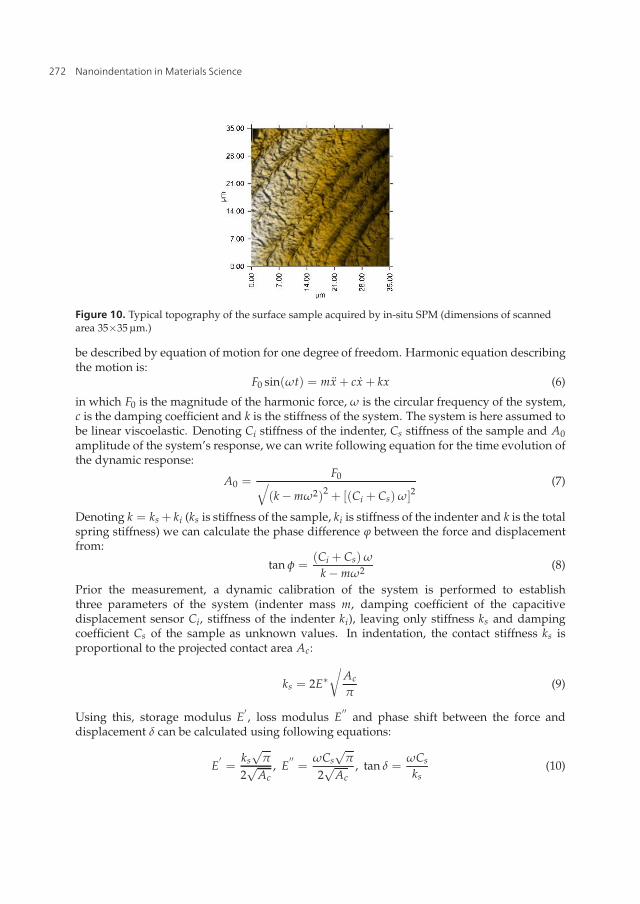
To measure elastic properties in a larger area (35×35 μm) of trabecula’s cross-section, modulusmapping technique (combination of nanoDMA and in-situ SPM) was used. In this process,the probe is sinusoidally oscillating over the polished surface with a given frequency andload. From the recorded displacement amplitude and phase lag storage and loss modulaeare determined. During MM a small sinusoidal force is superimposed on top of a largerquasi-static force. Motion of the vibrating system of indenter and the surface sample can
271Nanoindentation of Human Trabecular Bone –
Tissue Mechanical Properties Compared to Standard Engineering Test Methods
14 Will-be-set-by-IN-TECH
Figure 10. Typical topography of the surface sample acquired by in-situ SPM (dimensions of scannedarea 35×35 μm.)
be described by equation of motion for one degree of freedom. Harmonic equation describingthe motion is:
F0 sin(ωt) = mx + cx + kx (6)
in which F0 is the magnitude of the harmonic force, ω is the circular frequency of the system,c is the damping coefficient and k is the stiffness of the system. The system is here assumed tobe linear viscoelastic. Denoting Ci stiffness of the indenter, Cs stiffness of the sample and A0amplitude of the system’s response, we can write following equation for the time evolution ofthe dynamic response:
A0 =F0√
(k − mω2)2+ [(Ci + Cs) ω]2
(7)
Denoting k = ks + ki (ks is stiffness of the sample, ki is stiffness of the indenter and k is the totalspring stiffness) we can calculate the phase difference ϕ between the force and displacementfrom:
tan φ =(Ci + Cs) ω
k − mω2 (8)
Prior the measurement, a dynamic calibration of the system is performed to establishthree parameters of the system (indenter mass m, damping coefficient of the capacitivedisplacement sensor Ci, stiffness of the indenter ki), leaving only stiffness ks and dampingcoefficient Cs of the sample as unknown values. In indentation, the contact stiffness ks isproportional to the projected contact area Ac:
ks = 2E∗√
Ac
π(9)
Using this, storage modulus E′, loss modulus E
′′and phase shift between the force and
displacement δ can be calculated using following equations:
E′=
ks√
π
2√
Ac, E
′′=
ωCs√
π
2√
Ac, tan δ =
ωCs
ks(10)
272 Nanoindentation in Materials Science

Nanoindentation of Human Trabecular Bone – Tissue Mechanical Properties Compared to Standard Engineering Test Methods 15
From the storage and loss modulae, complex modulus E∗ can be computed using:
E∗ = E′+ iE
′′(11)
As a result of the MM technique, the stiffness is continuously measured in the pixel matrixand the modulus includes the real and imaginary part providing the storage (E
′) and loss (E
′′)
modulae of the material.
3.5. Comparison with quasi-static nanoindentation
In our experiments, the 256×256 square matrix represented physical area 35×35 μm. In eachpoint of the matrix storage and loss modulae were evaluated. To compare results from MMtechnique with quasi-static indentation, each sample was indented with a set of 9 indentsin the center of the area used for MM. In quasi-static indentation, maximal force 1000 μN wasapplied in 5 s loading part, which was followed by 5 s holding part, finished with 5 s unloadingpart.
Modulus mapping shows the trend of larger stiffness in core, smaller values are measuredin superficial areas. Both quasi-static nanoindentation and MM can be used to measure theelastic properties of extracted trabeculae, however, to identify material constants for morecomplex material model (e.g. von Mises plasticity with kinematic hardening) it is necessaryto use different experimental program, e.g. nanoindentation with various strain rates ormicromechanical testing as will be described in the following chapter.
4. Micromechanical testing of isolated trabeculae
Apart from nanoindentation, delicate tensile or bending tests can be performed withextracted trabeculae. The most important advantage of micromechanical testing is that itis well-developed and straightforwad technique. Moreover, using mechanical testing it ispossible not only to measure the Young’s modulus, but also yield properties or properties atdifferent strain rates can be assessed. In this section a method for measuring elastic modulusand yield stress using micromechanical testing of individual trabeculae will be described indetail.
4.1. Shape from silhouettes
The difficulty of performing mechanical tests with samples of such small dimensions(diameter of an average human trabecula from proximal femur is about 100 μm) lies not onlyin complicated manipulation with the samples, but also in precision of the measurement.The dimensions of the samples must be measured with micrometer precision and due to theirregularity in the samples’ shape it is necessary to measure the real shape of each sample. Toassess the precise shape of the trabeculae, every sample can be scanned in a micro-CT device(resolution of 1-5 μm is needed) and its geometry reconstructed with filtered backprojectionfor the cone beam scanning geometry.
Another option is to reconstruct the 3-D shape of the sample from its silhouettes. Thisis a method commonly used to obtain 3-D shapes from silhouettes captured by multiplecameras with the volume intersection method. The problem is stated as follows: Given aset of calibrated images of an object taken from different angles can we reconstruct its 3-D
273Nanoindentation of Human Trabecular Bone –
Tissue Mechanical Properties Compared to Standard Engineering Test Methods

16 Will-be-set-by-IN-TECH
model? The simplest method to perform this reconstruction is to use the so called visualhull which is the shape maximally consistent with the silhouettes. The visual hull is theintersection of the silhouette cones produced by images taken from different viewpoints (seeFig. 11). It can be easily shown that the visual hull cannot capture concavities not visible in thesilhouettes which can lead to reconstruction artifacts such as erroneous additional connectedcomponents. In the reconstruction, the foreground object is separated from the backgroundby binary thresholding and silhouette image is this binary foreground/background image.
Figure 11. The principle of visual hull. It is the intersection of silhouette cones (green), which is abounding geometry of the object
Figure 12. Reconstruction of the geometry of extracted trabeculae. Only middle part of the sample(between the supports) is needed.
It can be shown that for convex objects the reconstruction from images converges to the trueshape as more view angles are added. This technique has been used in our experiments withisolated trabeculae. Prior the testing, each sample was mounted on a rotational stage drivenby stepper motor and its shade was captured with a CCD camera attached to a microscope.The sample was rotated by 360◦ in 1◦ increments and its silhouettes captured with the camera.From the shade images the real geometry of each sample was reconstructed with error lessthan 4%.
The geometry of the trabecula is represented by its surface given as a set of connected triangles(see Fig. 12). The volume of the sample is discretized with tetrahedral elements using aconstrained Delaunay approach [50]. After shape optimization of the tetrahedral elements,
274 Nanoindentation in Materials Science

Nanoindentation of Human Trabecular Bone – Tissue Mechanical Properties Compared to Standard Engineering Test Methods 17
mid-side nodes are added for more accurately calculated gradients in deflections, strains andstresses in all FE calculations.
4.2. Displacement tracking using DIC
To measure the applied load and displacements with high accuracy a novel experimentaldevice (Fig. 13) has been developed which enables to control the displacement of the loadingtip with sub-micron positioning capability by means of differential micrometer with 0.1 μmsensitivity. Positioning of the supports and the sample is provided by precision double-rowball bearing linear stages with 1 μm sensitivity. This very high accuracy in positioning isnecessary for perfect loading and exact geometry of the experimental setup (see the close-upview in Fig. 15a and Fig. 15b).
Figure 13. Experimental setup for the optical measurement of extracted trabecula in three-pointbending.
Figure 14. Close-up view of the sample showing the loading tip attached to the miniature load cell.High magnification (12×) lens on right.
The deformation of the sample is measured optically using a high-resolution CCD camera.The strain field is evaluated with an image correlation algorithm [51] applied to the part ofthe sample between the supports.
DIC is based on the maximization of a correlation coefficient that is computed in subsets ofthe image surrounding the measurement points. Correlation between the pixel intensity in theimage subsets between two corresponding images (at time ti and ti+1) is computed for every
275Nanoindentation of Human Trabecular Bone –
Tissue Mechanical Properties Compared to Standard Engineering Test Methods

18 Will-be-set-by-IN-TECH
measured point with a non-linear optimization technique (inverse compositional algorithm).Coefficients of the affine transformation between the deformed and original position are usedto compute the deformation gradient tensor F. Green-Lagrange deformation tensor is thencomputed from: E = 1
2 (FTF − I).
In the bending tests, only displacements are evaluated with DIC. The displacements are usedto find the best fit between the experimental results and results computed using FE simulationof the bending test with real geometry of the sample. This procedure is described in thefollowing text.
a) b)Figure 15. Three-point bending of isolated trabecula. Straight sample resting on supports with spanlength equal to 1 mm (a). Principle of tracking "markers" on the sample using DIC (b).
4.3. Results from 3-point bending
To account for the real geometry of each irregularly shaped specimen, FE model reflectingthe true geometry is developed using the shape-from-silhouettes approach. Exact position ofthe supports and the loading tip is established from the high-resolution images. Boundaryconditions and loading of the FE model are prescribed to match exactly the experimentalconditions for each sample. Using similar fitting procedure as described for the FE modelof nanoindentation a set of material parameters is determined to find the best fit betweenthe experimental force–displacement curves and those determined from the numericalsimulation.
Because the displacements are actually measured in three distinct locations (using the imagecorrelation), the same positions are determined in the FE model and displacements in eachload increment are calculated in these points. Values from the FE simulation are comparedto the measured values. Example of the best-fit for selected “markers” in the FE model aredepicted (together with displacement field in the model) in Fig. 16.
276 Nanoindentation in Materials Science

Nanoindentation of Human Trabecular Bone – Tissue Mechanical Properties Compared to Standard Engineering Test Methods 19
Figure 16. Example of fitting the force-deflection curves calculated by the FE model to experimentallydetermined ones (left). Only part of the sample between the supports is considered by the FE model ofthe specimen’s real geometry(right).
4.4. Results from micromechanical testing compared to nanoindentation
To compare nanoindentation with micromechanical testing, only the elastic properties weredetermined by the two different methods. For the nanoindentation, only parts of thetrabeculae outside the supports were used. In this region, the bending moment is zero andthis part of the sample can be considered undamaged. After the bending test, each samplewas embedded in the upright position in the low shrinkage epoxy resin and polished toreveal the cross-section close to one of the ends of trabecula. After surface polishing thenanoindentation experiments described in section 3 were undertaken. Elastic propertiesobtained from nanoindentation and those assessed by the micromechanical bending tests arecompared in Tab. 4.
sample No. quasi-static nanoindentation [GPa] bending test [GPa]
1 12.04 11.07
2 15.93 13.26
3 16.22 13.87
4 17.82 14.52
5 17.91 14.70
6 12.07 10.51
Table 4. Average values of elastic modulae obtained by quasi-static indentation in the cross-section ofeach trabecula compared to the results of micromechanical tests with single trabecula (three-pointbending)
From Tab. 4 it is clear, that both methods give very similar results in terms of elastic properties.The values of elastic modulus measured by three-point bending are 10% - 20% lower thatthose assessed by nanoindentation. This can be explained by the fact that nanoindentationis not performed in the very outer part of the cross-section, thus giving more informationabout the core hardness, which is stiffer. Another reason might be in overestimation of
277Nanoindentation of Human Trabecular Bone –
Tissue Mechanical Properties Compared to Standard Engineering Test Methods

20 Will-be-set-by-IN-TECH
the cross-sectional area by the shape-from-silhouettes method. The overestimation of thecross-sectional area is well under 3%, however, the calculation of bending stiffness can lead tooverestimation over 5%.
5. Application to constitutive modeling of trabecular bone tissue
The importance of assessment of mechanical properties at the tissue level, i.e. at the levelof single trabeculae can be demonstrated using indirect determination of trabecular bonemechanical properties from high-resolution images of its internal architecture. These micro-FEmodels, i.e. models properly describing the geometry of the trabecular bone architecture arenowadays a common tool for assessment of mechanical properties of trabecular bone [52].The high-resolution images can be obtained from micro-CT images, peripheral quantitativecomputed tomography (pQCT) or, more recently with high-resolution magnetic resonance(MR) imaging.
These models can be used to study the relation between the microstructure, materialproperties at the tissue level and overall mechanical properties. It can be used to predictevolution of mechanical properties with osteoporotic changes to the microstructure and thusto assess evolution of osteoporotic fracture risk. Moreover, combined with experimental testswith small-scale samples of trabecular bone, these models can be used to verify the tissueconstitutive models. This can be achieved by comparing the response of micro-FE model withthe response of the real sample.
Additionally, microtomographic scanning of a sample can be performed in a time-lapsefashion, i.e. a sequence of a time-lapse micro-CT [53] of the specimen under graduallyincremented load is performed and the deformed microstructure is recorded. A custom,laboratory micro-radiographic system composed of micro-focus X-ray tube and a large flatpanel detector [54] can be used for such an experiment. Reconstruction of the internalstructure is provided using backprojection algorithm for equiangular cone-beam projectiondata [55] for each load increment.
To compare the strains in the loaded sample to the values calculated by the FE analysis aDigital Volume Correlation (DVC) [56, 57] method is used. DVC can be seen as a naturalextension of existing digital image correlation techniques [59] to three dimensions. Exampleof a comparison between the experimentally measured strain distribution in a loaded sampleand numerical simulation can be found in [58].
The bone microstructure can be discretized using a tetrahedral mesh. In the nodal pointsof the mesh the displacement vector is computed using X-ray digital volumetric correlationtechnique. For each of the tetrahedral element the Green-Lagrange strain tensor is calculatedfrom the displacements of its vertices. The overlaid tetrahedral mesh serves not only for thecalculation of the deformation tensor, but also for easy visualization of the vector and tensorfields and for fast and direct comparison with results of numerical simulations. The numericalsimulations can use the existing tetrahedral mesh or the mesh can be easily refined/coarsenedif needed. Illustrative example of the FE model and displacement field computed with DIC isshown in Fig. 18.
278 Nanoindentation in Materials Science

Nanoindentation of Human Trabecular Bone – Tissue Mechanical Properties Compared to Standard Engineering Test Methods 21
revolver with Al discsfor beam hardedningcorrection
X-ray source(1um spot)
trabecular bone sample(5mm diameter)
100N load cell
rotary table
X-ray detector
micrometer for loading
Figure 17. Experimental setup for time-lapse X-ray rentgenography. Sample is tested in three-pointbending and X-ray projections of the deformed state are captured using exposures with very small time(250 ms)
Figure 18. Small part of the micro-FE model of trabecular bone. FE mesh of the model (a) anddisplacement field (b). Illustrative image.
6. Conclusions
An overview of techniques used to determine material properties of trabecular bone atdifferent microstructural levels was presented in the chapter. The focus was paid ontwo important methods for measurement of mechanical properties at the tissue level: i)nanoindentation and ii) micromechanical testing. In the part focused on nanoindentation twomethods, i.e. quasi-static indentation and modulus mapping were compared. Apart frommeasurement of the elastic properties, a method based on fitting the response of FE model ofindentation to experimental curves was introduced.
Apart from nanoindentation, another approach to measure material properties of trabeculaewas described. This approach is based on precise micromechanical tests performed withindividual trabeculae. A methodology how to account for the imperfect shape of the
279Nanoindentation of Human Trabecular Bone –
Tissue Mechanical Properties Compared to Standard Engineering Test Methods

22 Will-be-set-by-IN-TECH
small-scale specimens was introduced. This methodology is based on developing exact FEmodel of each tested specimen using the shape-from-silhouettes approach. Discussion ofprecision of the measurements as well as precision of the geometry reconstruction was shortlygiven.
In the last part of the chapter, application of the tissue material properties to modeling oftrabecular bone was given. Short description of the development process of micro-FE models,i.e. FE models of the trabecular micro-architecture was described and utilization of microfocusComputed Tomography or other high-resolution imaging methods was outlined.
Precise and reliable measurement of tissue mechanical properties of trabecular bone as akey factor for the overall bone strength is important not only for reliable assessment ofosteoporotic fracture risk assessment but also for precise evaluation of the effects of treatmentprocedures, e.g. in animal studies. Although the term bone quality is poorly defined, it isclear that current diagnostic techniques for measuring the bone quality in vivo do not yieldreliable results. To improve the current diagnostic methods all the influencing factors, i.e.tissue properties, geometric, microarchitectural and connectivity factors, must be taken intoaccount and a combination of all described methods must be used.
Acknowledgements
Support of the Czech Science Foundation (P105/10/2305) is gratefully acknowledged.
Author details
Ondrej JiroušekInstitute of Theoretical and Applied MechanicsAcademy of Sciences of the Czech Republic, v.v.i.,Prague, Czech Republic
7. References
[1] Birkenhager-Frenkel DH, Nigg AL, Hens CJJ, Birkenhager JC. Changes of interstitialbone thickness with age in men and women. Bone 1993; 14(3) 211-216.
[2] Boyde A, Elliott JC, Jones SJ. Stereology and histogram analysis of backscattered electronimages: Age changes in bone. Bone 1993; 14(3) 205-210.
[3] van der Linden JC, Birkenhager-Frenkel DH, Verhaar JAN, Weinans H. Trabecularbone’s mechanical properties are affected by its non-uniform mineral distribution.Journal of Biomechanics 2001; 34(12) 1573-1580.
[4] Parfitt AM. The composition, structure and remodeling of bone a basis for theinterpretation of bonemineral measurements. In: Dequeker J, Geusens P, WahnerHW. (eds.) Bone Mineral Measurements by Photon Absorptiometry: MethodologicalProblems, 1988; Leuven University Press, Leuven, 9-28.
[5] Petersen MM, Gehrchen PM, Nielsen PK, Lund B. Loss of bone mineral of the hipassessed by DEXA following tibial shaft fractures. Bone 1997; 20(5), 491-495.
280 Nanoindentation in Materials Science

Nanoindentation of Human Trabecular Bone – Tissue Mechanical Properties Compared to Standard Engineering Test Methods 23
[6] Pafumi C, Chiarenza M, Zizza G. Role of DEXA and ultrasonometry in the evaluationof osteoporotic risk in postmenopausal women. Maturitas 2002; 42 113-117.
[7] Cummings SR, Bates D, Black DM. Clinical use of bone densitometry: scientific review.JAMA 2002; 288 1889-1897.
[8] Silva MJ, Gibson LJ. Modeling the mechanical behavior of vertebral trabecular bone:Effects of age-related changes in microstructure. Bone 1997; 21(2) 191-199.
[9] Sievanen H, Weynand LS, Wacker WK, Simonelli C, Burke PK, Ragi S, Del Rio L. A NovelDXA-Based Hip Failure Index Captures Hip Fragility Independent of BMD. Journal ofClinical Densitometry 2008; 11(3) 367-372.
[10] Wren TAL, Liu X, Pitukcheewanont P, Gilsanz V. Bone Densitometry in PediatricPopulations: Discrepancies in the Diagnosis of Osteoporosis by DXA and CT. TheJournal of Pediatrics 2005; 146(6) 776-779.
[11] Carte DR, Hayes WC. The compressive behavior of bone as a two-phase porousstructure. Journal of Bone and Joint Surgery - Series A 1977; 59 (7) 954-962.
[12] Goldstein SA. The mechanical properties of trabecular bone: Dependence on anatomiclocation and function. Journal of Biomechanics 1987; 20 (11-12) 1055-1061.
[13] Deligianni DD, Maris A, Missirlis YF. Stress relaxation behaviour of trabecular bonespecimens. Journal of Biomechanics 1994; 27 (12) 1469-1476.
[14] van Rietbergen B, Odgaard A, Kabel J, Huiskes R. Direct mechanics assessment of elasticsymmetries and properties of trabecular bone architecture. Journal of Biomechanics1996; 29 (12) 1653-1657.
[15] Wolfram U, Wilkea H, Zysset PK. Transverse isotropic elastic properties of vertebraltrabecular bone matrix measured using microindentation (effects of age, gender andvertebral level). Bone 2009; 44 S392–S393.
[16] Reisinger AG, Pahr DH, Zysset PK. Principal stiffness orientation and degree ofanisotropy of human osteons based on nanoindentation in three distinct planes Journalof the Mechanical Behavior of Biomedical Materials 2011; 4 (8) 2113-2127.
[17] Yamashita J, Li X, Furman BR, Rawls HR, Wang X, Agrawal CM. Collagen andbone viscoelasticity: A dynamic mechanical analysis. Journal of Biomedical MaterialsResearch 2002; 63 (1) 31-36.
[18] Wang X, Bank RA, Tekoppele JM and Agrawal CM. The role of collagen in determiningbone mechanical properties. Journal of Orthopaedic Research 2001; 19 1021–1026.
[19] Bembey AK, Bushby AJ, Boyde A, Ferguson VL, Oyen ML. Hydration effects onthe micro-mechanical properties of bone. Journal of Materials Research 2006; 21(8)1962-1968.
[20] Broz JJ, Simske SJ, Greenberg AR, Luttges MW. Effects of rehydration state on theflexural properties of whole mouse long bones. Journal of Biomechanical Engineering1993; 115 (4 A) 447-449.
[21] Bembey AK, Oyen ML, Bushby AJ, Boyde A. Viscoelastic properties of bone as a functionof hydration state determined by nanoindentation. Philosophical Magazine 2006; 86(33-35) 5691-5703.
[22] Oliver WC and Pharr GM. An improved technique for determining hardness and elasticmodulus using load and displacement sensing indentation experiments. Journal ofMaterials Research 1992; 7(6) 1564-1583.
281Nanoindentation of Human Trabecular Bone –
Tissue Mechanical Properties Compared to Standard Engineering Test Methods

24 Will-be-set-by-IN-TECH
[23] Pharr GM. Measurement of mechanical properties by ultra-low load indentation.Materials Science and Engineering A 1998; 253(1-2) 151-159.
[24] Pharr GM, Oliver WC, Brotzen FR. On the generality of the relationship among contactstiffness, contact area, and the elastic modulus during indentation. Journal of MaterialsResearch 1992; 7(3) 613–617.
[25] Dumas G, Baronet CN. Elastoplastic indentation of a half-space by an infinitely longrigid circular cylinder. International Journal of Mechanical Sciences 1971; 13 (6) 519-530.
[26] Hardy C, Baronet CN, Tordion GV. Indentation of an elastic-perfectly-plastic half-spaceby a hard sphere. Journal of Basic Engineering 1972; 94(1) 251-253.
[27] Cheng YT, Cheng CM. Scaling Relationships in Conical Indentation of Elastic PerfectlyPlastic Solids. International Journal of Solids Structures 1999; 36 1231–1243.
[28] Wang X, Allen MR, Burr DB, Lavernia EJ, Jeremic B, Fyhrie DP. Identification of materialparameters based on Mohr–Coulomb failure criterion for bisphosphonate treated caninevertebral cancellous bone. Bone 2008; 43 (4) 775-780.
[29] Jiroušek, O., Nemecek, J., Kytýr, D., Kunecký, J., Zlámal, P., Doktor, T., Nanoindentationof trabecular bone-comparison with uniaxial testing of single trabecula. Chemicke Listy2011; 105 (17) s668-s671.
[30] Rho JY, Tsui TY, Pharr GM. Elastic properties of human cortical and trabecular lamellarbone measured by nanoindentation. Biomaterials 1997; 18(20) 1325-1330.
[31] Zysset PK, Guo XE, Hoffler CE, Moore KE, Goldstein SA. Elastic modulus and hardnessof cortical and trabecular bone lamellae measured by nanoindentation in the humanfemur. Journal of Biomechanics 1999; 32(10) 1005-1012.
[32] Turner CH, Rho J, Takano Y, Tsui TY, Pharr GM. The elastic properties of trabecular andcortical bone tissues are similar: Results from two microscopic measurement techniques.Journal of Biomechanics 1999; 32(4) 437-441.
[33] Rho JY, Roy ME 2nd, Tsui TY, Pharr GM. Elastic properties of microstructuralcomponents of human bone tissue as measured by nanoindentation. Journal ofBiomedical Materials Research 1999; 45(1) 48-54.
[34] Hoffler CE, Moore KE, Kozloff K, Zysset PK, Brown MB, Goldstein SA. Heterogeneityof bone lamellar-level elastic moduli. Bone 2000; 26(6) 603-609.
[35] Hengsberger S, Kulik A, Zysset P. Nanoindentation discriminates the elastic propertiesof individual human bone lamellae under dry and physiological conditions. Bone 2002;30(1) 178-184.
[36] Roschger P, Paschalis EP, Fratzl P, Klaushofer K. Bone mineralization densitydistribution in health and disease. Bone 2008; 42(3) 456-466.
[37] Zhang J, Michalenko MM, Kuhl E. Characterization of indentation response andstiffness reduction of bone using a continuum damage model. Journal of the mechanicalbehavior of biomedical materials 2010; 3(2), 189-202.
[38] Zlámal P, Jiroušek O, Kytýr D, Doktor T. Indirect determination of materialmodelparameters for single trabecula based o nanoindentation and three-point bendingtest. Proceedings of the 18th international conference Engineering Mechanics 2012; 1394-395.
[39] Brennan O, Kennedy OD, Lee TC, Rackard SM, O’Brien FO Biomechanical propertiesacross trabeculae from the proximal femur of normal and ovariectomised sheep. Journalof Biomechanics 2009; 42(4) 498-503.
282 Nanoindentation in Materials Science

Nanoindentation of Human Trabecular Bone – Tissue Mechanical Properties Compared to Standard Engineering Test Methods 25
[40] Jiroušek O, Kytýr D, Zlámal P, Doktor T, Šepitka J, Lukeš J. Use of modulus mappingtechnique to investigate cross-sectional material properties of extracted single humantrabeculae. Chemické Listy 2012; accepted.
[41] Dudíková M, Kytýr D, Doktor T, Jiroušek O. Monitoring of material surface polishingprocedure using confocal microscope. Chemické Listy 2011; 105(17) 790-791.
[42] Tang B and Ngan AHW. Accurate measurement of tip–sample contact size duringnanoindentation of viscoelastic materials. Journal of Materials Research 2003; 181141-1148.
[43] Oyen ML, Cook RF. A practical guide for analysis of nanoindentation data. Journal ofthe Mechanical Behavior of Biomedical Materials 2009; 2(4) 396-407.
[44] Nemecek J. Creep effects in nanoindentation of hydrated phases of cement pastes.Materials Characterization 2009; 60(9) 1028–1034.
[45] Mencík J, He LH, Nemecek J. Characterization of viscoelastic-plastic properties of solidpolymers by instrumented indentation. Polymer Testing 2011; 30 101–109.
[46] Sneddon IN. The relation between load and penetration in the axisymmetric Boussinesqproblem for a punch of arbitrary profile. International Journal of Engineering Science1965; 3(1) 47-57.
[47] Asif SA, Wahl KJ, Colton RJ, Warren OL. Quantitative imaging of nanoscale mechanicalproperties using hybrid nanoindentation and force modulation. Journal of AppliedPhysics 2001; 90(3) 1192-1200.
[48] Khanna R, Katti SK, Katti DR. Bone Nodules on Chitosan-PolygalacturonicAcid-Hydroxyapatite Nanocomposite Films Mimic Hierarchy of Natural Bone. ActaBiomaterialia 2011; 7 1173-1183.
[49] Balooch G, Marshall GW, Marshall SJ, Warren OL, Asif SAS, Balooch M. Evaluation ofa new modulus mapping technique to investigate microstructural features of humanteeth. Journal of Biomechanics 2004; 37 1223-1232.
[50] Edelsbrunner H and Shah NR. Incremental Topological Flipping Works for RegularTriangulations. Algorithmica 1996; 15 223-241.
[51] Jandejsek I, Valach J, Vavrík D. Optimization and Calibration of Digital ImageCorrelation Method. In Experimentální analýza napetí 2010. Olomouc: UniverzitaPalackého v Olomouci, 121-126.
[52] Verhulp E, van Rietbergen B, Müller R, Huiskes R. Indirect determination oftrabecular bone effective tissue failure properties using micro-FE simulations. Journalof Biomechanics 2008; 41(7) 1479-1485.
[53] Nazarian A. and Müller R. Time-lapsed microstructural imaging of bone failurebehavior. Journal of Biomechanics 2004; 37(1) 55-65.
[54] Jakubek J, Holy T, Jakubek M, Vavrik D, Vykydal Z. Experimental system for highresolution X-ray transmission radiography. Nuclear Instruments and Methods inPhysics Research Section A: Accelerators, Spectrometers, Detectors and AssociatedEquipment 2006; 563(1), 278-281.
[55] Vavrík D, Soukup P. Metal grain structure resolved with table-top micro-tomographicsystem. Journal of Instrumentation 2011; 6 (11), art. no. C11034.
[56] Jiroušek O, Jandejsek I, Vavrík D. Evaluation of strain field in microstructures usingmicro-CT and digital volume correlation. Journal of Instrumentation 2011; 6 (1), art. no.C01039.
283Nanoindentation of Human Trabecular Bone –
Tissue Mechanical Properties Compared to Standard Engineering Test Methods

26 Will-be-set-by-IN-TECH
[57] Jandejsek I, Jiroušek O, Vavrík D. Precise strain measurement in complex materials usingdigital volumetric correlation and time lapse micro-CT data. Procedia Engineering 2011;10(1) 1730-1735.
[58] Jiroušek O, Zlámal P, Kytýr D, Kroupa M. Strain analysis of trabecular bone usingtime-resolved X-ray microtomography. Nuclear Instruments and Methods in PhysicsResearch, Section A: Accelerators, Spectrometers, Detectors and Associated Equipment2011; 633 (SUPPL. 1) S148-S151.
[59] Lucas BD and Kanade T. An iterative image registration technique with an application tostereo vision. Proceedings of the 1981 DARPA Image Understanding Workshop, April,1981 121-130.
284 Nanoindentation in Materials Science