Embed Size (px)
Citation preview

4
© 2018 GomSpace A/S
NanoCam C1U Datasheet Camera payload for nano-satellites
© 2018 GomSpace A/S All printed copies, and all electronic copies and versions except the one accessible on
the GomSpace A/S server, are considered uncontrolled copies used for reference only.
Datasheet NanoCam C1U
06 August 2018
DS 1010105 1.8
2
Product name: NanoCam C1U
Document No.: 1010105
Revision: 1.8
Author: KLK
Approved by: LMR
Approval date: 6 August 2018
Confidentiality Notice
This document is submitted for a specific purpose as agreed in writing and contains information,
which is confidential and proprietary. The recipient agrees by accepting this document, that this
material will not be used, transferred, reproduced, modified, copied or disclosed in whole or in
part, in any manner or to any third party, except own staff to meet the purpose for which it was
submitted without prior written consent.
GomSpace © 2018
© 2018 GomSpace A/S All printed copies, and all electronic copies and versions except the one accessible on
the GomSpace A/S server, are considered uncontrolled copies used for reference only.
Datasheet NanoCam C1U
06 August 2018
DS 1010105 1.8
3
1 Table of Contents
2 OVERVIEW ............................................................................................................................................... 4
2.1 Highlighted Features .................................................................................................................... 4
2.2 Configuration ............................................................................................................................... 5
2.3 Lens Table ................................................................................................................................... 5
2.4 Block Diagram ............................................................................................................................. 6
2.4.1 Processor ..................................................................................................................................... 6
2.4.2 Storage ........................................................................................................................................ 7
2.4.3 Image sensor ............................................................................................................................... 7
2.4.4 F-RAM & RTC .............................................................................................................................. 7
2.4.5 Interfaces ..................................................................................................................................... 7
2.4.6 GOSH .......................................................................................................................................... 7
2.4.7 Sensors ........................................................................................................................................ 7
2.5 Lenses ......................................................................................................................................... 8
3 HARDWARE LAYOUT ............................................................................................................................. 9
3.1 J1: USB Connector ...................................................................................................................... 9
3.2 J2: GOSH Connector ................................................................................................................. 10
3.3 J3: Main Connector .................................................................................................................... 10
4 DATA INTERFACE ................................................................................................................................. 11
4.1 CAN ........................................................................................................................................... 11
4.2 I2C .............................................................................................................................................. 11
4.3 RS-422 ....................................................................................................................................... 11
4.4 Serial Port .................................................................................................................................. 11
5 ABSOLUTE MAXIMUM RATINGS ......................................................................................................... 12
6 ELECTRICAL CHARACTERISTICS ...................................................................................................... 12
6.1 Power Usage ............................................................................................................................. 12
7 PHYSICAL CHARACTERISTICS ........................................................................................................... 12
8 MECHANICAL DRAWING ...................................................................................................................... 13
8.1 70 mm ........................................................................................................................................ 13
8.2 35 mm - 1U version ................................................................................................................... 14
9 DISCLAIMER .......................................................................................................................................... 14

© 2018 GomSpace A/S All printed copies, and all electronic copies and versions except the one accessible on
the GomSpace A/S server, are considered uncontrolled copies used for reference only.
Datasheet NanoCam C1U
06 August 2018
DS 1010105 1.8
4
2 Overview The NanoCam C1U system is a flexible and modular system to rapidly implement tailored imaging systems
based on customer requirements. It is an off-the-shelf configuration consisting off: lens, lens table, image
acquisition, processing board, and software.
NanoCam C1U has been designed to be implementable in a standard 1U CubeSat structure together with
GomSpace’s on-board computers, attitude control system, radio transceiver and power products to allow low
cost Earth observation using CubeSats.
This is the new upgraded version of the GomSpace NanoCam C1U, with upgraded image processing
capabilities.
2.1 Highlighted Features
Integrated System:
• Industrial Lens
• 3-megapixel color sensor
• Capable data processing and storage on-board
Image Acquisition:
• 1/2” (4:3) format color CMOS sensor
• 2048 x 1536 pixels
• 10-bit RGGB Bayer pattern
Lens Performance:
• Three high-end industrial lenses o 8 mm f/1.4 o 35 mm f/1.9 o 70 mm f/2.2
• 8 mm lens: <260 m/pixel from 650 km
• 35 mm lens: <60 m/pixel from 650 km
• 70 mm lens: <30 m/pixel from 650 km
• 400-750 nm spectral transmission
Data Processing:
• High-performance ARM processor
• 512 MB on-board DDR2 RAM
• 2 GB solid state image storage
• RAW, BMP and JPEG output formats
Interface:
• CSP-enabled CAN, I2C, RS-422 and TTL level serial interfaces
• Serial port with text-based console
Quality:
• Glass/Polyimide IPC 6012C cl. 3/A
• IPC-A-610 Class 3 assembly

© 2018 GomSpace A/S All printed copies, and all electronic copies and versions except the one accessible on
the GomSpace A/S server, are considered uncontrolled copies used for reference only.
Datasheet NanoCam C1U
06 August 2018
DS 1010105 1.8
5
2.2 Configuration The C1U is based on an industrial compact C-mount optical system from Schneider Optics. The lens mounts in
the lens table, which is the main load bearing part of the system. The image sensor is located at the topside of
the camera printed circuit board, beneath the lens table and interfaces to the image processor and memory
components on the bottom side of the board. A heat and EMI shield covers the bottom side of the camera PCB.
2.3 Lens Table The lens table can be mounted either pointing up or down (like in the drawing above). It is per default mounted
pointing down, except if it is to be mounted in a 1U satellite.
70 mm Lens
Lens table
Baffle
J1 connector
PCB
Heat / EMI shieldJ3 connector
J2 connector
© 2018 GomSpace A/S All printed copies, and all electronic copies and versions except the one accessible on
the GomSpace A/S server, are considered uncontrolled copies used for reference only.
Datasheet NanoCam C1U
06 August 2018
DS 1010105 1.8
6
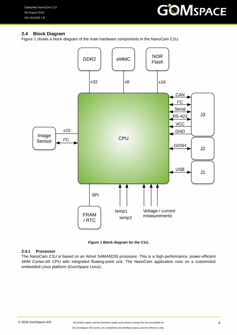
2.4 Block Diagram Figure 1 shows a block diagram of the main hardware components in the NanoCam C1U.
2.4.1 Processor
The NanoCam C1U is based on an Atmel SAMA5D35 processor. This is a high-performance, power-efficient
ARM Cortex-A5 CPU with integrated floating-point unit. The NanoCam application runs on a customized
embedded Linux platform (GomSpace Linux).
Figure 1 Block diagram for the C1U.
CPU
DDR2 eMMCNORFlash
ImageSensor
FRAM / RTC
J1
J3
USB
SPI
x32 x16x8
x10
I2C
temp1
temp2
Voltage / currentmeasurements
J2GOSH
CAN
I2C
Serial
RS-422
VCC
GND

© 2018 GomSpace A/S All printed copies, and all electronic copies and versions except the one accessible on
the GomSpace A/S server, are considered uncontrolled copies used for reference only.
Datasheet NanoCam C1U
06 August 2018
DS 1010105 1.8
7
2.4.2 Storage
The board includes 512 MB DDR2 memory for image storage and processing. A 4 GB eMMC flash is used for
the root file system and for persistent storage of captured images. 2 GB of the flash is available for image
storage. The system boots from a dedicated 64 MB NOR flash attached to the processors external bus interface.
2.4.3 Image sensor
A key component of the NanoCam is the Aptina MT9T031 digital image sensor. This 1/2“ CMOS sensor
produces color images up to 2048x1536 pixels resolution with 10-bit per pixel ADC resolution. It is connected
to the main processor with a 10-bit parallel interface for data and I2C for control of image parameters.
2.4.4 F-RAM & RTC
For storage of non-volatile configuration and telemetry data, the C1U board includes a 32 kB Ferroelectric RAM
(F-RAM) from Cypress Semiconductor. The stored data is accessible through the GomSpace parameter
system. The F-RAM provides virtually unlimited write-erase cycles and also includes a built-in capacitor-backed
Real-Time Clock (RTC) that is used to maintain system time across reboots and short periods without power.
2.4.5 Interfaces
The camera is controlled using the Cubesat Space Protocol (CSP) via CAN, I2C, RS-422 or TTL level serial
port. Multiple interfaces can be enabled simultaneously to use different interfaces to communicate with different
subsystems on the satellite bus.
2.4.6 GOSH
A serial console provides access to operation and debugging commands through the GomSpace shell (GOSH).
The serial console also allows access to the standard Linux shell.
2.4.7 Sensors
The NanoCam includes two analog temperature sensors, plus voltage and current sensors on the 3.3 V (VCC),
1.8 V (DDR2) and 1.2 V (CPU) power rails. These values can be read through the parameter system.

© 2018 GomSpace A/S All printed copies, and all electronic copies and versions except the one accessible on
the GomSpace A/S server, are considered uncontrolled copies used for reference only.
Datasheet NanoCam C1U
06 August 2018
DS 1010105 1.8
8
2.5 Lenses The C1U is designed to accommodate any lens that conforms to the C-mount interface. It has been tested with
the Schneider Optics Industrial Ruggedized 2/3” format lenses. The following features apply to all these lenses:
• 2/3” format
• 11 mm image circle
• 400-750 nm pass band
• Corrected and broadband coated
• Robust metal body
• Precise focusing via fine internal thread
• Unique, robust focus lock
• Click-stop free iris setting / Iris lock
• Integrated front thread to accept SN2 mount filters
The C1U is supplied with a (removable) Schneider Kreuznach BP 540-300 (486) HT UV/IR cut filter, that blocks
UV light below 390 nm and IR above 690 nm. Other filter options are available on request.
The following standard lenses from Schneider Optics have been tested with the C1U:
Cinegon 1.4/8-0902
F-number: 1.4
Focal length: 8,2 mm
Length from flange: 32.4 mm
Filter thread: M30.5x0.5
Mass: 90 g
XENOPLAN 1.9/35MM
COMPACT
F-number: 1.9
Focal length: 34.9 mm
Length from flange: 34.7 mm
Filter thread: M30.5x0.5
Mass: 92 g
TELE-XENAR 2.2/70MM
COMPACT
F-number: 2.2
Focal length: 70.5 mm
Length from flange: 74.0 mm
Filter thread: M40.5x0.5
Mass: 200 g

© 2018 GomSpace A/S All printed copies, and all electronic copies and versions except the one accessible on
the GomSpace A/S server, are considered uncontrolled copies used for reference only.
Datasheet NanoCam C1U
06 August 2018
DS 1010105 1.8
9
3 Hardware Layout The NanoCam C1U has three connectors on the topside of the PCB, labeled J1, J2, and J3. The connector
locations are highlighted in the figure below.
3.1 J1: USB Connector J1 is a standard USB Micro-B connector used for production and update of the system firmware. It is not possible
use USB for general operation of the NanoCam.
Figure 2 Topside hardware layout with connectors and pin numbers.

© 2018 GomSpace A/S All printed copies, and all electronic copies and versions except the one accessible on
the GomSpace A/S server, are considered uncontrolled copies used for reference only.
Datasheet NanoCam C1U
06 August 2018
DS 1010105 1.8
10
3.2 J2: GOSH Connector Picoblade. Right angle. Molex 53261-0471
J2 provides access to the GomSpace Shell (GOSH), which is used for integration and debugging purposes.
The interface uses 3.3 V UART levels.
Pin Description
1 GND
2 Not Connected
3 DRXD
4 DTXD
3.3 J3: Main Connector Picoblade. Right angle. Molex 53261-1571
This connector is used for supplying power to the C1U and for interfacing with other subsystems.
Pin Description
1 GND
2 I2C SCL (CSP I2C Clock)
3 I2C SDA (CSP I2C Data)
4 VCC (3.3 V)
5 CANL (CSP CAN Low)
6 CANH (CSP CAN High)
7 VCC (3.3 V)
8 UART-TXD0 (CSP via TTL Serial)
9 UART-RXD0 (CSP via TTL serial)
10 GND
11 RX P (CSP RS-422, positive receive)
12 TX N (CSP RS-422, negative transmit)
13 TX P (CSP RS-422, positive transmit)
14 RX N (CSP RS-422, negative receive)
15 GND

© 2018 GomSpace A/S All printed copies, and all electronic copies and versions except the one accessible on
the GomSpace A/S server, are considered uncontrolled copies used for reference only.
Datasheet NanoCam C1U
06 August 2018
DS 1010105 1.8
11
4 Data Interface The NanoCam C1U uses the CubeSat Space Protocol (CSP) to transfer data to and from other CSP nodes on
the main system bus. CSP is a routed network protocol that can be used to transmit data packets between
individual subsystems on the satellite bus and between the satellite and ground station. For more information
about CSP please read the documentation on http://www.libcsp.org and on Wikipedia:
http://en.wikipedia.org/wiki/Cubesat_Space_Protocol
The camera can be operated via CSP on four interfaces: CAN, I2C, RS422 and TTL level serial port. It is possible
to enable multiple interfaces simultaneously and use different interfaces for different subsystems on the satellite
bus.
4.1 CAN The CAN interface to the C1U can be used together with CAN Fragmentation Protocol (CFP), a data-link layer
protocol specially developed for CSP. CFP is a simple method to make CSP packets of up to 256 bytes span
multiple CAN frames of up to 8 bytes each. The CAN rate is configured to 1 Mb/s.
4.2 I2C The NanoCam can also be operated over multi-master I2C. The C1U uses the same I2C address as the CSP
network address per default. Please note that since the CSP router sends out an I2C message automatically
when data is ready for a subsystem residing on the I2C bus, the bus must be operated in I2C multi-master mode.
I2C slave mode is thus not supported. The I2C rate is set to 400 kb/s.
4.3 RS-422 The NanoCam also supports CSP over a RS-422 serial port using the KISS framing protocol. The default serial
port rate is 500 kb/s. (Note RS-422 and TTL level serial port cannot be used simultaneously)
4.4 Serial Port The NanoCam also supports CSP over TTL level serial port using the KISS framing protocol. The default serial
port rate is 500 kb/s. (Note RS-422 and TTL level serial port cannot be used simultaneously)
© 2018 GomSpace A/S All printed copies, and all electronic copies and versions except the one accessible on
the GomSpace A/S server, are considered uncontrolled copies used for reference only.
Datasheet NanoCam C1U
06 August 2018
DS 1010105 1.8
12
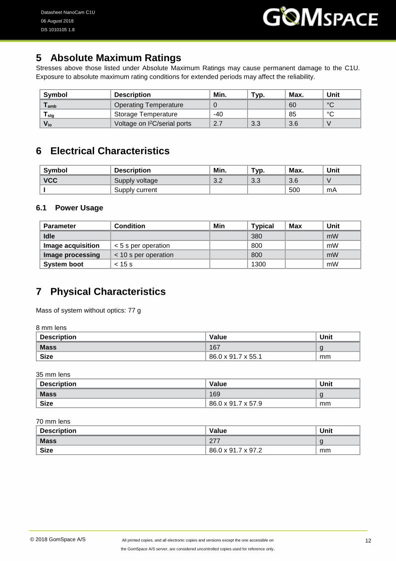
5 Absolute Maximum Ratings Stresses above those listed under Absolute Maximum Ratings may cause permanent damage to the C1U.
Exposure to absolute maximum rating conditions for extended periods may affect the reliability.
Symbol Description Min. Typ. Max. Unit
Tamb Operating Temperature 0 60 °C
Tstg Storage Temperature -40 85 °C
Vio Voltage on I2C/serial ports 2.7 3.3 3.6 V
6 Electrical Characteristics
Symbol Description Min. Typ. Max. Unit
VCC Supply voltage 3.2 3.3 3.6 V
I Supply current 500 mA
6.1 Power Usage
Parameter Condition Min Typical Max Unit
Idle 380 mW
Image acquisition < 5 s per operation 800 mW
Image processing < 10 s per operation 800 mW
System boot < 15 s 1300 mW
7 Physical Characteristics
Mass of system without optics: 77 g
8 mm lens
Description Value Unit
Mass 167 g
Size 86.0 x 91.7 x 55.1 mm
35 mm lens
Description Value Unit
Mass 169 g
Size 86.0 x 91.7 x 57.9 mm
70 mm lens
Description Value Unit
Mass 277 g
Size 86.0 x 91.7 x 97.2 mm
© 2018 GomSpace A/S All printed copies, and all electronic copies and versions except the one accessible on
the GomSpace A/S server, are considered uncontrolled copies used for reference only.
Datasheet NanoCam C1U
06 August 2018
DS 1010105 1.8
13
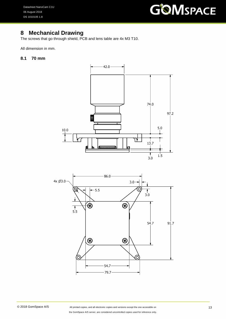
8 Mechanical Drawing The screws that go through shield, PCB and lens table are 4x M3 T10.
All dimension in mm.
8.1 70 mm

© 2018 GomSpace A/S All printed copies, and all electronic copies and versions except the one accessible on
the GomSpace A/S server, are considered uncontrolled copies used for reference only.
Datasheet NanoCam C1U
06 August 2018
DS 1010105 1.8
14
8.2 35 mm - 1U version
9 Disclaimer The information in this document is subject to change without notice and should not be construed as a
commitment by GomSpace. GomSpace assumes no responsibility for any errors that may appear in this
document.
In no event shall GomSpace be liable for incidental or consequential damages arising from use of this document
or the software and hardware described in this document.