Embed Size (px)
Citation preview

1
Nancy Nesky
From: Ben King <[email protected]>Sent: Monday, September 24, 2012 6:08 PMTo: '[email protected]'; Nancy Nesky; '[email protected]';
'[email protected]'; '[email protected]'; '[email protected]'; '[email protected]'; '[email protected]'; '[email protected]'; '[email protected]'; '[email protected]'; '[email protected]'; '[email protected]'; '[email protected]'; [email protected]; '[email protected]'; Sandra Rode ([email protected]); [email protected]; PGAN; Ailiang Gu; Douglas Fisher; Dave Becker ([email protected]) ([email protected]); Jeff Littell
Cc: Koehne, Stephanie; '[email protected]'; '[email protected]'; Daus, Tony; 'Abilzi' ([email protected]); Dennis Petrocelli; Harry Brenton; Minnier, Gwen E; Panday, Sorab; Patel, Nimisha; Tom Demichele; Zoe McCraw; Jody Lee Mack; Patrick Hunnewell; Corkery, Emily; Richards, Kate; Yang, Gao; [email protected]; Cindy Pries; Michele Rogers
Subject: PGA-N Final EA-08 Construction Completion Report for the Augmentation of Subunit A Plume Containment in the North Central Area
Attachments: EA08 GTS CCR_09242012.pdf; Fig 1 - EA-08 GTS Site Location Map.pdf; Fig 2 - Site Plan.pdf; Fig 3 - Extraction Well and Piezometer Well Construction Diagram.pdf
Follow Up Flag: Follow upFlag Status: Flagged
Dear Ms. Brown, Please find attached the Final Construction Completion Report for the Augmentation of Subunit A Plume Containment in the North Central Area for the Phoenix-Goodyear Airport-North Superfund Site located in Goodyear, Arizona. Due to size considerations, the Appendices for this document have not been included with this email but will be available for download from the project website and submitted in the final hardcopies. The document is referenced as item #17A on the most recent PGA-North Action Items and Deliverables List. If you have any questions or comments, please do not hesitate to contact me. Regards, Ben King, P.E. Senior Engineer Matrix New World Engineering, Inc. 250 N. Litchfield Rd. Suite 201 Goodyear AZ, 85338 P.480.389.7197 F.973.240.1818
www.matrixneworld.com Certified WBE, DBE, SBE Business
SDMS DOCID#1142247

2

CONSTRUCTION COMPLETION REPORT
FOR THE AUGMENTATION OF SUBUNIT A PLUME CONTAINMENT IN THE NORTH CENTRAL AREA
PHOENIX-GOODYEAR AIRPORT-NORTH SUPERFUND SITE GOODYEAR, MARICOPA COUNTY, ARIZONA
Prepared for: Crane Co. 100 First Stamford Place, Suite 400 Stamford, CT 06902
Prepared by: Matrix New World Engineering, Inc.
250 Litchfield Road, Suite 201 Goodyear, AZ 85338
September 24, 2012 Matrix No. 12-100E

F:\2011\11-100E Crane Co. PGA North\GTS\EA-08\Construction Completion\EA08 GTS CCR_09242012.doc i
CONSTRUCTION COMPLETION REPORT FOR THE AUGMENTATION OF SUBUNIT A PLUME CONTAINMENT
IN THE NORTH CENTRAL AREA PHOENIX-GOODYEAR AIRPORT-NORTH SUPERFUND SITE
GOODYEAR, MARICOPA COUNTY, ARIZONA September 24, 2012 Brian D. Stabile Date Geologist Matrix New World Engineering, Inc. September 24, 2012 Michele Rogers, E.I.T Date Civil Engineer Matrix New World Engineering, Inc. September 24, 2012 Benjamin King, P.E. Date Senior Engineer Matrix New World Engineering, Inc. September 24, 2012 Harry Brenton, R.G. Date Principal Hydrogeologist Matrix New World Engineering, Inc.

F:\2011\11-100E Crane Co. PGA North\GTS\EA-08\Construction Completion\EA08 GTS CCR_09242012.doc ii
TABLE OF CONTENTS
1.0 Introduction and Background ........................................................................................................ 1 2.0 General Geology and Hydrogeology ............................................................................................. 2 3.0 Pre-construction Access Agreement and Permitting Activities ..................................................... 4
3.1 Arizona Department of Water Resources Permit ................................................................. 4 3.2 Maricopa County Dust Control Permit .................................................................................. 4 3.3 Roosevelt Irrigation District Canal Access Agreement ......................................................... 4 3.4 Pre-Construction Survey ...................................................................................................... 4 3.5 Utility Clearance ................................................................................................................... 5 3.6 City of Goodyear Traffic Control Permit ............................................................................... 5 3.7 City of Goodyear Construction Permit .................................................................................. 5 3.8 City of Goodyear Fire, Building and Life Safety Permit ........................................................ 5 3.9 City of Goodyear Site Plan Approval .................................................................................... 5
4.0 Extraction Well EA-08 Construction Activities ............................................................................... 6 4.1 Pre-Field Activities................................................................................................................ 6 4.2 Borehole Drilling and Soil Sampling ..................................................................................... 6 4.3 Well Construction ................................................................................................................. 7 4.4 Well Development ................................................................................................................ 8 4.5 Well Performance and Aquifer Testing ............................................................................... 10 4.6 Piezometer Well PZ-15 ...................................................................................................... 11
5.0 Interim Groundwater Treatment System Construction Activities ................................................. 12 5.1 Process Description ........................................................................................................... 12 5.2 Process Components ......................................................................................................... 13
5.2.1 Liquid Phase GAC System ..................................................................................... 13 5.2.2 Pre-Treatment System ........................................................................................... 13 5.2.3 System Tie-ins and Piping ...................................................................................... 14 5.2.4 Process Instrumentation and Controls ................................................................... 15 5.2.5 Well Pump .............................................................................................................. 15 5.2.6 Electrical Service .................................................................................................... 16 5.2.7 Treatment Structure ................................................................................................ 16 5.2.8 Hydrostatic Testing ................................................................................................. 17
5.3 Liquid Phase GAC Monitoring ............................................................................................ 18 5.4 EA-08 System Operation and Maintenance ....................................................................... 19 5.5 EA-08 Discharge ................................................................................................................ 19
6.0 References .................................................................................................................................. 21 List of Figures
1 EA-08 GTS Site Location Map 2 Site Plan 3 Extraction Well and Piezometer Well Construction Diagram

F:\2011\11-100E Crane Co. PGA North\GTS\EA-08\Construction Completion\EA08 GTS CCR_09242012.doc iii
Table of Contents, Cont. List of Appendices Appendix A ADWR Permit Application Package
Appendix B Maricopa County Dust Control Permit Appendix C RID Access Agreement Appendix D COG Traffic Control Permits Appendix E COG Construction Permit Appendix F COG Fire, Building and Life Safety Permit Appendix G COG Site Plan Approval Notice Appendix H Well Construction Photo Log Appendix I EA-08 Lithologic Log Appendix J Grain Size Analysis for Filter Pack and Screen Design Appendix K Well and Sounding Tube Pipe Tally Sheets Appendix L Annular Material Records Appendix M Performance Sample Analytical Results Appendix N Well Development Records Appendix O PZ-15 Lithologic Log Appendix P As-Built Drawings Appendix Q LGAC Vessel Information Appendix R Siemens LGAC Media Information Appendix S Hayward Multi-bag Filter Vessel Information Appendix T Badger Flow Meter Manual Appendix U Presidio Systems Schematic Drawings Appendix V Barksdale Pressure Transmitter Information Appendix W Sierra Wireless Raven X Cellular Modem Information
Appendix X Grundfos 475S400-5B Pump Technical Data Appendix Y Geotechnical Memorandum Appendix Z Geomembrane Installation Specifications Appendix AA ATL, Inc. Materials Testing Laboratory Report Appendix BB Field Documentation of Hydrostatic Testing Appendix CC EA-08 GTS Startup Analytical Data Reports

F:\2011\11-100E Crane Co. PGA North\GTS\EA-08\Construction Completion\EA08 GTS CCR_09242012.doc 1
1.0 INTRODUCTION AND BACKGROUND
Matrix New World Engineering, Inc. (Matrix), on behalf of Crane Co., has prepared this Construction
Completion Report for the Augmentation of Subunit A Plume Containment in the North Central Area
(Report) to document construction activities associated with the EA-08 Groundwater Treatment System
(EA-08 GTS), located at 3112 North Litchfield Road, Goodyear Arizona (Site [Figure 1]). The EA-08
GTS included the drilling and installation of one groundwater extraction well (EA-08), the drilling and
installation of one piezometer well (PZ-15) and the construction of one interim liquid granular activated
carbon (LGAC) groundwater treatment system (Figure 2) as part of the overall approach to contain the
northwest portion of the Subunit A plume of trichloroethene (TCE) in the northern plume. All activities
summarized herein were conducted in general accordance with the Work Plan for Augmentation of
Subunit A Plume Containment in the North Central Area dated February 28, 2011 (Matrix 2011a [Work
Plan]) that was approved by the United States Environmental Protection Agency (USEPA) on March
31, 2011. An Addendum – Work Plan for Augmentation of Subunit A Plume Containment in the North
Central Area (Matrix 2011b [Work Plan Addendum]), was submitted to the USEPA on May 13, 2011 to
document alternative pad construction techniques that deviated from the EA-08 concrete pad and
secondary containment construction methods outlined in the approved Work Plan.
The EA-08 GTS was installed based on technical evaluation of available monitoring data from monitor
wells EPA MW-38A and EPA MW-50A, which indicate TCE concentrations that exceed the Federal
Maximum Contaminant Level (MCL) of 5 micrograms per liter (μg/L), and the lack of hydraulic capture
between extraction wells 33A and EA-06 identified in the Draft Subunit A Capture Zone Report (AMEC
2011). The objectives, rationale, and design concepts for extraction well EA-08 were anticipated to
provide the following:
Complete capture of the Subunit A TCE plume in the north central area, Reduce TCE concentrations in monitor well EPA MW-50A, and Provide an interim/temporary treatment system for rapid construction and implementation.
All interim treatment system concepts and designs were also reviewed with USEPA and stakeholder
personnel during a conference call held on September 30, 2010 and at the quarterly technical meeting
on November 3, 2010.

F:\2011\11-100E Crane Co. PGA North\GTS\EA-08\Construction Completion\EA08 GTS CCR_09242012.doc 2
2.0 GENERAL GEOLOGY AND HYDROGEOLOGY
The Phoenix-Goodyear Airport – North (PGA-North) Site is located in the West Salt River Valley
(WSRV) basin, which is part of the Basin and Range physiographic province (Basin & Range). The
Basin & Range is characterized by deep alluvial basins separated by generally north to northwest
trending mountain ranges. Locally, the WSRV alluvial deposits are subdivided into three hydrogeologic
units. These three units are designated as the Upper Alluvial Unit (UAU), the Middle Alluvial Unit
(MAU), and the Lower Alluvial Unit (LAU). The UAU is further subdivided near the PGA-North Site into
three subunits, which are designated Subunit A, Subunit B, and Subunit C.
Upper Alluvial Unit
This section summarizes the composition of Subunits A, B, and C of the UAU.
Subunit A
Subunit A is generally composed of interbedded sands, silty sands, and clayey sands that can locally
contain sequences of gravel and cobbles suggesting high energy deposits from the ancestral Agua Fria
River. Subunit A typically extends from ground surface to approximately 150 to 160 feet below ground
surface (bgs) in the vicinity of the PGA-North Site and generally deepens to the north in the vicinity of
the EA-08 GTS, to depths of approximately 190 to 220 feet bgs. Approximately one-third to one-half of
the lower portion of Subunit A is saturated and is considered an unconfined aquifer.
Subunit B
Subunit B is primarily composed of interbedded silts and clays with lenses of fine to coarse sand
suggesting distal facies of an alluvial fan sequence. It is generally 50 to 70 feet thick near the PGA-
North Site extending from about 160 to 230 feet bgs and is fully saturated. The deposits in Subunit B
are suggested to be a combination of distal facies of regressive alluvial fan sequences and/or over
bank flood deposits from the Ancestral Agua Fria River. Field data collected from the groundwater
investigations suggest that the thickness and surface topography is variable. It deepens and thins (20
to 70 feet thick) north of Interstate-10 and it may not be laterally continuous near the Agua Fria River
channel. However, where Subunit B is present, the finer-grained deposits appear to impede the vertical
movement of groundwater from Subunit A into Subunit C.

F:\2011\11-100E Crane Co. PGA North\GTS\EA-08\Construction Completion\EA08 GTS CCR_09242012.doc 3
Subunit C
Subunit C is composed of interbedded mixtures of silty sands, sandy silts, and gravelly sands
suggesting mid-fan facies of a regressive alluvial fan sequence with braided channels. On average
Subunit C is approximately 130 feet thick and extends from about 230 to 350 feet bgs. Subunit C is
fully saturated and is considered to be a leaky to confined aquifer.
Middle Alluvial Unit
The UAU grades into the MAU at approximately 350 to 360 feet bgs. The MAU primarily consists of
clay, silt, mudstone, and gypsiferous mudstone with interbedded sand and gravel deposits. In the
central portions of the WSRV, the MAU may be up to 1,600 feet thick (Corell and Corkhill 1994).
Lower Alluvial Unit
The LAU is the deepest alluvial unit within the WSRV and overlies or is in fault contact with the
underlying bedrock. Regionally, the LAU is composed of conglomerate and gravel near the basin
margins, grading to mudstone and some local evaporites in the central areas of the basin. No wells
within the PGA-North Site are completed within the LAU. Hydraulic conductivity of the LAU is variable
ranging from 5 to 60 feet/day (Corell and Corkhill, 1994).
F:\2011\11-100E Crane Co. PGA North\GTS\EA-08\Construction Completion\EA08 GTS CCR_09242012.doc 4
3.0 PRE-CONSTRUCTION ACCESS AGREEMENT AND PERMITTING ACTIVITIES
Before drilling or construction activities related to the EA-08 GTS commenced, pre-construction permits
were applied for and approved by the responsible local, state and federal regulatory agencies, and an
access agreement between the Roosevelt Irrigation District (RID) and Crane Co. was established. A
summary of the RID access agreement and permits obtained for drilling and construction of the EA-08
GTS are provided in the subsections below.
3.1 Arizona Department of Water Resources Permit
Prior to the installation of the well, a Notice of Intent (NOI) to Drill permit application package was
submitted, to the Arizona Department of Water Resources (ADWR). The package included the NOI to
Drill application, the proposed well design diagram, specifications, and the permit application fee. A
copy of the ADWR permit application package is located in Appendix A.
3.2 Maricopa County Dust Control Permit
A dust control permit package was submitted to the Maricopa County Air Quality Department on March
15, 2011. The Maricopa County Air Quality Department approved the application and issued Dust
Control Permit number E110370. A copy of the Maricopa County Dust Control Permit is located in
Appendix B.
3.3 Roosevelt Irrigation District Canal Access Agreement
In order to discharge treated effluent into the RID Canal, an access agreement was reached with the
RID. Treated groundwater from the EA-08 GTS is discharged to the RID Canal in accordance with the
signed Agreement and Perpetual Easement to Construct, Maintain, and Remove Conveyance
Infrastructure on the Roosevelt Irrigation District Right-of-Way dated August 30, 2011, and notarized on
September 1, 2011. Additionally, per the RID Canal Access Agreement, Matrix submitted a legal
description of the EA-08 GTS to the RID on November 7, 2011. Permit number 181300155-22 was
issued to Crane Co. by the RID in the Right-of-Way Crossing Permit on September 14, 2011. Copies
of the RID Access Agreement, legal description, and Right-of-Way crossing permit are included in
Appendix C.
3.4 Pre-Construction Survey
On April 8, 2011, a preconstruction survey of the Site was performed at the request of the City of
Goodyear (COG). Representatives from Matrix and the COG surveyed the Site for preexisting
F:\2011\11-100E Crane Co. PGA North\GTS\EA-08\Construction Completion\EA08 GTS CCR_09242012.doc 5
conditions. This included an inspection of the condition of the adjacent sidewalk and all landscaping
within the COG Right-of-Way.
3.5 Utility Clearance
Prior to mobilization, Arizona Blue Stake was contacted to locate existing underground utilities in the
Site vicinity. Visible color-coordinated paint markings were made in the vicinity of utilities before the
pre-construction survey to ensure that the well drilling and treatment system construction would not
interfere with existing utilities.
3.6 City of Goodyear Traffic Control Permit
A pedestrian traffic control permit associated with sidewalk closure was required to detour pedestrian
traffic from the sidewalk adjacent to the Site in order to ensure the safety of the public. An approved
traffic control permit (Number 11-792) was issued on April 13, 2011 and was extended on June 3, 2011
by the COG. Copies of the Traffic Control Permits are located in Appendix D.
3.7 City of Goodyear Construction Permit
The COG approved Construction Permit number 11-1147 on July 28, 2011. A copy of the COG
Construction Permit is located in Appendix E.
3.8 City of Goodyear Fire, Building and Life Safety Permit
A permit application package was submitted on May 18, 2011, to the COG Fire Department. The COG
approved of Fire, Building and Life Safety Permit number 11-1271 on July 28, 2011. A copy of the Fire,
Building and Life Safety Permit and the legal description are located in Appendix F.
3.9 City of Goodyear Site Plan Approval
The COG approved the EA-08 GTS site plan, case number 11-600-00003, on March 30, 2011. A copy
of the Site Plan Approval Notice is located in Appendix G.

F:\2011\11-100E Crane Co. PGA North\GTS\EA-08\Construction Completion\EA08 GTS CCR_09242012.doc 6
4.0 EXTRACTION WELL EA-08 CONSTRUCTION ACTIVITIES
Drilling and installation of extraction well EA-08 was conducted by Yellow Jacket Drilling (YJD) (ADWR
License Number 78) from April 11 through June 21, 2011 using a Foremost DR24 HD Dual Rotary drill
rig. Prior to mobilization, the well was permitted through the ADWR by filing a NOI to Drill permit
(Section 3.1). The ADWR assigned well registration number for the EA-08 well is 55-913204. EA-08
well installation and construction activities are summarized in the following sections. A well
construction photo log, including photographs of well drilling, installation, and testing is presented in
Appendix H.
The general chronology of the drilling and well construction is presented below:
April 11, 2011 – Drill Rig mobilization April 14, 2011 – Drilling began May 26, 2011 – Reached a total depth tagged at 229.75 feet bgs and began well construction May 27, 2011 – Annular material placement began June 17, 2011 – Well Construction Complete June 20, 2011 – Initial swab and airlift well development June 21, 2011 – Drill Rig demobilization
4.1 Pre-Field Activities
Prior to initiating field activities, the following pre-field activities were performed:
Submitted a Notification of Initiation of Fieldwork to the USEPA 15 days prior to the initiation of field activities;
Obtained the necessary permits from the ADWR and procured right-of-access agreements from the COG (Section 3.1);
Obtained traffic control permits for side walk closure and utility permits from COG (Section 3.6);
Contacted Arizona Blue Stake to clear the proposed extraction well EA-08 location for public
utilities (Section 3.5); and
Distributed the COG approved resident advisory notice to the residents of the neighborhood where field activities were to be performed.
4.2 Borehole Drilling and Soil Sampling
A 24-inch diameter borehole was drilled using dual rotary drilling methodologies from April 14 through
May 26, 2011 to a total depth of 229.75 feet bgs. Soil lithologic logging activities were performed by a
Matrix field geologist under the supervision of an Arizona licensed Registered Geologist. Lithology was
assessed from the drill cuttings and logged using the United Soil Classification System (USCS) as
described in American Society for Testing and Materials (ASTM) International Standard D 2488-09a

F:\2011\11-100E Crane Co. PGA North\GTS\EA-08\Construction Completion\EA08 GTS CCR_09242012.doc 7
(ASTM 2009). Visual grain-size distribution, color, and other pertinent characteristics were also
included on the lithologic log presented as Appendix I.
Representative samples were collected from cuttings at 5-foot intervals or at major lithologic changes.
The materials encountered during drilling consisted of unconsolidated mixtures of clay, silt, sand, and
gravel. Initial groundwater was encountered at approximately 135 feet bgs. The lithology is generally
consistent with basin fill deposits in the WSRV Sub-basin of the Phoenix Active Management Area
(AMA) and other Subunit A wells within the PGA-North area. Depth specific grab samples collected
from the drill cuttings from 145 feet bgs, 155 feet bgs, 165 feet bgs, 175 feet bgs, 185 feet bgs and 190
feet bgs, along with a bulk sample from 150 feet bgs to 190 feet bgs, were submitted to a Roscoe-Moss
Materials Testing Laboratory in Los Angeles, California, for grain size analysis to determine the filter
pack size and slot size of the screen material. The grain size distribution curve and a copy of the
geotechnical lab results are presented in Appendix J.
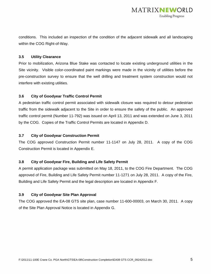
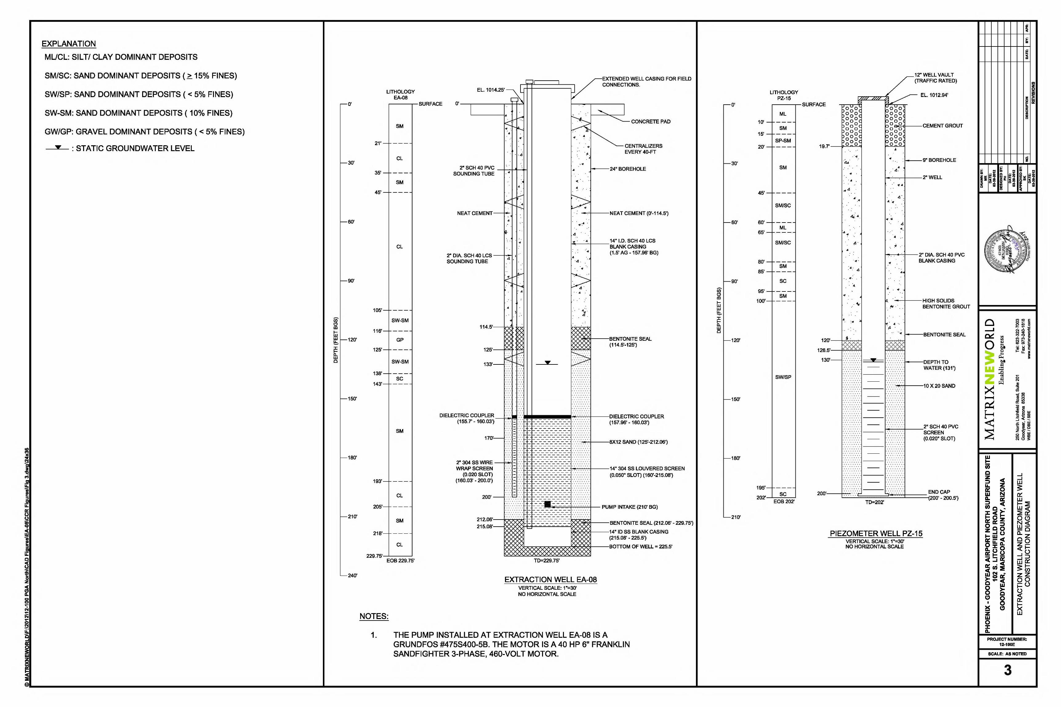
4.3 Well Construction
Well construction activities were performed from May 26 through June 17, 2011. Based on the results
of the grain size analysis and estimated flow rate of 250 to 400 gallons per minute (gpm), extraction
well EA-08 was constructed using 14-inch diameter casing with louvered screen (slot size 0.050-inch)
with an 8x12 gravel pack. A 2-inch sounding tube was constructed within the annulus between the well
casing and the formation. The extraction well construction diagram is presented in Figure 3. Prior to
construction, the grain size analysis and well design specifications were reviewed and agreed upon by
the USEPA and other Stakeholders.
After approval and acceptance of well design by the USEPA during a conference call, the final
proposed well design was submitted to the drillers to order the materials. During construction, well pipe
tally sheets were used to record each piece of well and sounding tube that was placed in the borehole
(Appendix K). A summary of the well and sounding tube materials is presented below:
Well:
14-inch diameter low carbon steel (LCS) blank casing stickup from 0-feet to approximately 1.5-feet above grade,
14-inch diameter LCS blank riser pipe from 0 feet to 157.96 feet bgs, 14-inch diameter dielectric coupler from 157.96 feet to 160.0 feet bgs, 14-inch diameter stainless steel louvered screen (0.050-inch) from 160 feet to 215.08 feet bgs, and 14-inch diameter stainless steel blank casing from 215.08 feet to 225.5 feet bgs.

F:\2011\11-100E Crane Co. PGA North\GTS\EA-08\Construction Completion\EA08 GTS CCR_09242012.doc 8
Sounding Tube:
2-inch diameter LCS blank riser pipe from 0 feet bgs to 158.7 feet bgs, 2-inch diameter dielectric coupler from 158.7 feet bgs to 160.03 feet bgs, and 2-inch diameter stainless steel wire-wrap screen (0.030-inch slot) from 160.03 feet bgs to 200 feet
bgs.
The well and sounding tube were constructed by welding together sections of the LCS casing, the
dielectric coupler, and stainless steel screen while hanging the casing string in the borehole. On the
well, centralizers were welded at approximately 40-foot intervals. After all sections were welded, the
casing remained hanging five feet off of the bottom of the borehole until the annular materials were
added.
Once the well casing and sounding tube were installed to the depths listed above, emplacement of
annular materials began on May 27, 2011 using a Tremie pipe. The calculated values for the annular
materials were checked against actual soundings within the annulus during emplacement to determine
the geometry of the pipe. Chlorine powder was added periodically during gravel pack emplacement as
a disinfectant. The well screen was swabbed periodically during placement of the gravel pack to settle
the gravel pack around the well screen and reduce the potential for bridging. A copy of annular
material records can be found in Appendix L. A summary of annular material construction from top to
bottom is as follows:
Grout was placed from 0 feet to 114.5 feet bgs, An upper bentonite seal was placed from 114.5 feet bgs to 125 feet bgs, An 8x12 Colorado silica sand filter pack was placed from 125 feet bgs to 212.06 feet bgs, and A lower bentonite seal was placed from 212.06 feet bgs to 229.75 feet bgs.
4.4 Well Development
Upon completion of the well on June 17, 2011, including placement of all annular materials, the well
was initially developed by YJD by swabbing and airlifting using a 10-foot double-flanged perforated
swabbing tool. Prior to the initial development, Aquaclear phosphate free detergent (PFD) was added
to the well to help breakdown the drilling fluid and borehole wall cake. Frac tanks were used to
separate the solids from the water prior to treatment using a temporary LGAC unit and discharge to the
RID Canal. Swabbing and airlifting was conducted in 10-foot sections within the screen interval of the
well. Water parameters (pH, temperature, and conductivity) were collected at appropriate intervals
during airlifting to monitor the progress of development. On June 21, 2011, once swabbing and
airlifting was complete, the drill rig and equipment were demobilized from the Site.

F:\2011\11-100E Crane Co. PGA North\GTS\EA-08\Construction Completion\EA08 GTS CCR_09242012.doc 9
Upon completion of the LGAC treatment system, additional well development was conducted on the
well to continue to remove fines, drilling mud and additives from the gravel pack and borehole wall.
During this process, all development water was containerized in a vertical 6,000-gallon above ground
polyethylene holding tank. Containerized water was pumped through a temporary treatment system
consisting of a transfer pump, two multi-bag filter housings plumbed in parallel, and two 2,000-pound
(lb) LGAC adsorbers plumbed in series to remove any volatile organic compounds (VOCs). All treated
effluent was finally pumped to the RID Canal and discharged. Matrix obtained the required approval
from the RID before discharging treated water to the RID Canal. Performance samples of the treated
water were collected prior to discharge to the RID Canal and analyzed for VOCs. The results of the
sample analysis were non-detect for VOCs. The results of the laboratory analysis are included in
Appendix M.
On September 19, 2011, Empire Pump Corporation, doing business as (dba) Duncan Pump (Duncan)
mobilized a Smeal 5T Pump rig to conduct swabbing and bailing of the well. The swabbing procedure
consisted of working the well screen in 10-foot intervals from the bottom of the well toward the top.
Generally, swabbing continued for approximately 10 minutes per foot of well screen or for a total of 9
hours. The well was then bailed to remove the fine grained sediment and drilling mud that was
liberated by the swabbing process. Swabbing activities liberated approximately nine cubic feet of
material.
On September 26, 2011, Duncan installed a temporary test pump to further develop the well using
pump and surge methodologies and to get a general knowledge of the specific capacity and efficiency
of the well. Pump and surge activities were conducted at pumping rates starting at 100 gpm, followed
by rates of 150 gpm and 200 gpm. The pump and surge process consisted of cycles of 20 minutes of
pumping, followed by surging the well five times in succession by shutting the pump off and allowing
water in the column pipe to flow back into the well and into the gravel pack and formation. At the end of
each 20 minute pumping cycle, measurements of sand content, turbidity, and depth to water were
collected. However, at a flow rate of approximately 200 gpm, the specific capacity values were lower
than expected [3.35 gpm/foot (ft)] and it was noticed that air entrainment was occurring in the
discharge. This suggested that more aggressive development was necessary to improve the well
efficiency and specific capacity. As such, the temporary pump was removed and additional Aquaclear
PFD was added to prepare the well for more aggressive swabbing with concurrent airlifting.

F:\2011\11-100E Crane Co. PGA North\GTS\EA-08\Construction Completion\EA08 GTS CCR_09242012.doc 10
From September 29 through October 3, 2011, Duncan performed additional swabbing and airlifting
using a Smeal 5T Pump rig. The swabbing was conducted using similar processes described above
with concurrent airlifting to immediately remove the liberated fine grained sediment, drilling fluid and
additives. It is estimated that airlifting occurred at a rate of approximately 20 to 30 gpm. During this
process sand content was measured using an Imhoff cone. It is estimated that approximately 10 cubic
feet of material was removed during this stage of development.
From October 11 through November 4, 2011, well development continued using both swab and pump
and surge methodologies. Duncan used a cable tool rig to conduct the swabbing and pumping of the
well using a submersible pump. This allowed for more aggressive swabbing than the Smeal 5T rig
could accommodate. The pump and surge was conducted similar to the procedures described above
at flow rates of 200 gpm, 250 gpm, and 300 gpm. During these processes depth to water was
measured within the gravel pack and well to monitor improvement in drawdown and subsequent
specific capacity. Sand and sediment content were monitored using an Imhoff cone and Rossum Sand
Tester. At the conclusion of the development activities specific capacity values improved and ranged
from 6.91 gpm/ft to 7.32 gpm/ft. However, air entrainment was still observed at flow rates near 300
gpm due to excessive drawdown in the well and a steep cone of depression.
A summary of the well development records are included in Appendix N.
4.5 Well Performance and Aquifer Testing
Aquifer testing will be conducted once the final flow rate of EA-08 is achieved. Although aquifer testing
has not been performed, well performance and pumping status at EA-08 has been closely monitored
since pumping began in December 2011. The pumping rates have been incrementally increased from
150 gpm to 380 gpm as of April 10, 2012. This was accomplished by stepping up pump rates at 10
gpm increments on a weekly basis. During this process, well drawdown and air entrainment has been
closely monitored and results indicate an improvement in performance with no signs of air entrainment.
For example, on December 19, 2011, the pumping rate was 190 gpm with an in well drawdown of 38.15
feet bgs and a specific capacity measured at 4.98 gpm/ft. On April 10, 2012, the pumping rate was 380
gpm with an in well drawdown of 38.45 feet bgs and the specific capacity was measured at 9.88 gpm/ft.
Using the Theis analytical solution, an estimate of hydraulic conductivity was calculated to be
approximately 29.3 feet/day based on March 23, 2012 data and the well efficiency was calculated to be
approximately 83%. Once the final flow rate from EA-08 is achieved, a 72-hour aquifer test and 48-

F:\2011\11-100E Crane Co. PGA North\GTS\EA-08\Construction Completion\EA08 GTS CCR_09242012.doc 11
hour recovery test will be conducted. This will allow for a more accurate determination of hydraulic
conductivity.
4.6 Piezometer Well PZ-15
Following the installation of extraction well EA-08, a Subunit A piezometer well (PZ-15) was installed
approximately 125 feet to the east of EA-08 (Figure 2) to provide drawdown data to estimate hydraulic
conductivity of the aquifer, estimate hydraulic capture, and estimate well efficiency. On September 13
and 14, 2011, AMEC oversaw the drilling of PZ-15 by Layne Christensen using a percussion hammer
drill rig (AP-1000). The piezometer was installed to a depth of 200 feet bgs and was constructed of 2-
inch diameter Schedule (Sch) 40 polyvinyl chloride (PVC) pipe. The piezometer was screened from
130 feet bgs to 200 feet bgs. The final design for PZ-15 is illustrated on Figure 3 and the lithologic log
is included in Appendix O.

F:\2011\11-100E Crane Co. PGA North\GTS\EA-08\Construction Completion\EA08 GTS CCR_09242012.doc 12
5.0 INTERIM GROUNDWATER TREATMENT SYSTEM CONSTRUCTION ACTIVITIES
Construction of the EA-08 GTS was initiated on August 15, 2011, and system startup occurred on
December 7, 2011. The EA-08 GTS is located at 3112 North Litchfield Road, Goodyear Arizona, along
the RID Canal, within the COG Right-of-Way, adjacent to and just east of the EA-08 well (Figure 2).
The EA-08 GTS was constructed to remove VOCs, targeting TCE, from the EA-08 north central Subunit
A groundwater capture zone.
Extracted groundwater from EA-08 is treated at the EA-08 GTS compound using a Hayward Maxiline
mulit-bag filter for pretreatment and an LGAC system for VOC treatment. The LGAC System is
comprised of two 10,000-lb vessels connected in a lead/lag configuration. Treated effluent from the
EA-08 GTS is discharged to the RID Canal in accordance with the RID access agreement (Section
3.3). Details on the EA-08 GTS are provided in the subsections below.
5.1 Process Description
The process description for the EA-08 extraction and treatment system is as follows:
A 40-horsepower (Hp) submersible groundwater pump was sized and installed to extract up to 400 gpm of contaminated groundwater through the EA-08 GTS.
Groundwater is pre-filtered to remove particulate matter by a six bag multi-bag filter housing. The
filters are sized to remove particulate matter greater than 10 microns. Groundwater is then pumped through two 10,000-lb LGAC treatment vessels arranged in a series
treatment format. Following treatment, the treated groundwater is discharged to the RID Canal via temporary 6-inch
ductile iron pipe (DIP) below ground and 6-inch Sch 80 PVC above ground. At the actual discharge into the RID Canal, the exposed piping is also 6-inch DIP per RID requirements.
As-built figures are provided in Appendix P to illustrate the design and final construction of the EA-08
GTS. These include a Process and Instrumentation Diagram (P&ID), Facility Plan and Profile, and
Facility Profile and Details, including the RID outfall design (Appendix P). In addition, vendor supplied
information for the major process equipment has been provided in Appendices Q through X. As
integrated, these items result in a system that is capable of meeting the performance and design
specifications the USEPA approved in the EA-08 Work Plan and Work Plan Addendum. Additional
details for these items are included below.

F:\2011\11-100E Crane Co. PGA North\GTS\EA-08\Construction Completion\EA08 GTS CCR_09242012.doc 13
5.2 Process Components
Process components are explained in detail in the sub-sections below.
5.2.1 Liquid Phase GAC System
Based on the estimated extraction flow for EA-08, a two vessel series configuration was selected to
optimize LGAC utilization while providing a reliable system to continuously reduce TCE concentrations
below the USEPA MCL of 5 µg/L. The LGAC vessels were mounted to 1-inch thick steel plates to
distribute the loading within the system containment. Additional details are provided below:
LGAC Vessels: Crane Co. PV 10,000 System (two vessels and inter-connecting piping manifold
assembly). These vessels were chosen because they allow sufficient hydraulic loading (in excess of
the design flow rate of 400 gpm) and they allow sufficient volume of LGAC to maximize time between
LGAC change-outs and minimize treatment costs. LGAC vessel information is provided in Appendix Q.
LGAC Operation: Lead/Lag series configuration. Consistent with the other PGA-North GTSs where
liquid phase carbon is utilized, Matrix operates the EA-08 LGAC vessels in a lead/lag series
configuration to allow for the efficient utilization of the LGAC, and to maintain high effluent water quality.
The vessels are supplied with a valve manifold that allows for simple change-outs of the spent carbon
and changing the order of the lead and lag vessel configuration.
LGAC Media: Siemens Reactivated Coconut Carbon– Aquacarb S. The LGAC selected for this project
is Siemens reactivated coconut carbon, Aquacarb S. The decision to use the reactivated carbon was
based on the low concentrations of TCE and the operation and maintenance (O&M) cost savings over
virgin coconut shell carbon. This LGAC media has been successfully used at the EA-05 GTS, EA-06
GTS and 33A GTS since each was brought on-line. Siemens LGAC media information is provided in
Appendix R.
5.2.2 Pre-Treatment System
Based on historical concentrations of total suspended solids (TSS) in the influent groundwater
observed at other PGA-North area treatment systems, a pre-filtration system was installed in-line
between the extraction well and LGAC vessels to prevent and/or limit plugging of the LGAC and reduce
the need for backwashing. Matrix utilized a Hayward Maxiline MBF HE series, Model MBF0602-AB10-
060A-US-11HE multi-bag filter vessel for the EA-08 GTS to remove TSS prior to the LGAC vessels.

F:\2011\11-100E Crane Co. PGA North\GTS\EA-08\Construction Completion\EA08 GTS CCR_09242012.doc 14
The Hayward bag filter housing utilizes six bag filters and is designed to handle a maximum flow rate of
900 gpm.
Based on Site experience, filtration to 10 microns was utilized at the EA-08 GTS to remove particulates
before the LGAC vessels. The bag filter housing was mounted to a ¼-inch steel plate to distribute the
loading within the system containment area. The bag filters in the housing are replaced when the
differential pressure across the filter housing increases to approximately 10 to 14 pounds per square
inch (psi). The system control logic to shut down the system at a high differential pressure is field
adjustable and is currently set at 15 psi similar to other PGA-North GTSs. In the event a high
differential pressure condition is realized by the programmable logic control (PLC), an alarm will be
triggered, shutting down the GTS, and the operators will be notified of the alarm condition. The
Hayward multi bag filter vessel information is provided in Appendix S.
5.2.3 System Tie-ins and Piping
The EA-08 GTS includes the following influent and effluent connections:
6-inch Sch 80 PVC pipe and fittings from the wellhead to the bag filter housing, the bag filter housing by-pass, and to the influent connection on the carbon adsorber manifold, and from the effluent connection on the adsorber manifold to the RID discharge line.
The Sch 80 PVC transitions to Class 53 DIP and fittings, per RID requirements, immediately
outside of the EA-08 GTS compound. The transition was completed using a 6-inch Sch 80 PVC van stone flange mated to a 6-inch DIP flange adapter. The above ground discharge pipe at the RID Canal is also 6-inch DIP.
The DIP fittings and pipe were provided with a factory applied asphaltic material coating.
On the 6-inch influent and effluent pipe to and from the manifold, a Sch 80 PVC tee with a van
stone flange and blind flange mated together were provided. These connections were included to facilitate possible future system augmentation or reconfiguration. These connections were installed as shown in Appendix P.
Crane ductile iron butterfly valves, installed to control flow and isolate process equipment for
maintenance purposes, were installed in the Sch 80 PVC process piping (using van stone flanges to connect in line), and also included in the Crane Co. carbon adsorber manifold.
A 6-inch flow meter is installed after the multi-bag filter unit but before the LGAC vessels to
provide real time flow rate and totalized flow information to the operator. The flow meter is a Badger Meter M2000. The Badger Flow Meter Manual is included in Appendix T.
5.2.4 Process Instrumentation and Controls

F:\2011\11-100E Crane Co. PGA North\GTS\EA-08\Construction Completion\EA08 GTS CCR_09242012.doc 15
The instrumentation and controls for the EA-08 GTS were integrated into a process control system
similar to those in use at the EA-05 GTS and EA-06 GTS. The process control system was developed
by Presidio Systems, Inc. The Presidio Systems schematic drawings for the process control system
are provided in Appendix U. A PLC was installed with inputs and outputs to accommodate
communication and control of key components of the EA-08 GTS. The inputs that are monitored by the
PLC are the decision logic process parameters (i.e. system flow rates and pressures) that are used to
determine and control the operation of the entire treatment system. The outputs are used to control
specific process parameters (e.g., flow rate by controlling the groundwater extraction pump's variable
frequency drive [VFD]), record operational data, and allow the system to be monitored remotely.
The following instrumentation and controls are in use by the EA-08 GTS:
A Badger direct read magnetic flow meter model M2000 (Appendix T) with a signal output to the PLC is located after the multi-bag filter unit but before the LGAC vessels as shown in Appendix P. This flow meter is of a similar type and manufacture as those used on the EA-05 GTS and EA-06 GTS; and
Pressure gauges and a Barksdale Model No. 425N1-05-P2 pressure transmitter with a signal output to communicate with the PLC was installed to monitor system pressures throughout the process, including differential pressure across the multi-bag filter unit and both LGAC vessels. Pressure gauges and transmitters are located at the influent and effluent of the multi-bag filter unit, the LGAC vessels mid-point on the manifold and the system effluent. Barksdale pressure transmitter information is included in Appendix V.
A Sierra Wireless Raven-X Broadband Cellular Modem (CDMA channel configuration, network using
Verizon Wireless) was installed inside the motor circuit protector (MCP) enclosure. Matrix can access
the trend data (alarms, flow rate, flow totals to date, pressure) remotely through the internet using the
modem, and download the data remotely when necessary. The control panel vendor can also access
the PLC remotely through the modem in the event trouble-shooting is required, or
updates/modifications are required. The PLC provides the data logging capability and trend data for
the 40-Hp submersible well pump run time, logging of influent flow meter instantaneous rate and
totalizing function, alarm conditions, pressure transmitter readings, etc. Information related to the
Sierra Wireless Raven-X Broadband Modem is included in Appendix W
5.2.5 Well Pump
A 6-inch diameter Grundfos Model 475S400-5B, 40-Hp, electric, submersible, stainless steel pump is
installed in well EA-08 to extract groundwater. The pump is equipped with a PVC shroud to force
extracted water around the pump motor and promote cooling. The pump intake was installed to

F:\2011\11-100E Crane Co. PGA North\GTS\EA-08\Construction Completion\EA08 GTS CCR_09242012.doc 16
approximately 210 feet bgs and is supported by a 6-inch Sch 80 threaded and coupled carbon steel
vertical discharge pipe. The carbon steel discharge pipe has been electrically isolated from the
stainless steel pump with a dielectric coupler in order to prevent galvanic corrosion caused by dissimilar
metals contact. The well seal was completed with 2-inch access ports for installation of a sounding
tube and pressure transducer. The pump was sized to carry the water through the entire EA-08 GTS
system to the RID discharge location. The Grundfos 475S400-5B Pump technical data is provided in
Appendix X.
5.2.6 Electrical Service
The EA-08 GTS electrical power is provided by Arizona Public Service Co. (APS). In order to supply
the necessary 200 amp, 277/480 volt service entrance section (SES), APS installed electrical
transformers on a utility pole adjacent to the EA-08 GTS and a single 3-inch underground Sch 40 PVC
conduit was installed from the adjacent APS utility pole to the SES. The conduit and transformer were
installed on July 20, 2011 in compliance with APS installation and safety protocols. See Appendix P for
the on-site electrical as built.
5.2.7 Treatment Structure
The EA 08 GTS was built following the USEPA Superfund Green Remedial Strategy (USEPA 2010),
effectively reducing the environmental footprint of the construction effort by reducing the amount of
concrete placed and by using alternative construction materials in the design. Before construction of
the treatment system, four geotechnical borings were advanced in the area where the structure would
be located. A geotechnical memorandum dated September 1, 2011 is included as Appendix Y and
outlined the results of the geotechnical testing. The geotechnical memorandum indicated that the soils
underneath the EA-08 GTS provided sufficient bearing capacity to support the LGAC vessels and
related equipment and cleared the way for the use of the alternative construction techniques, which
utilized a containment area constructed out of a high density polyethylene (HDPE) geomembrane and
pressure treated 8-inch by 8-inch timbers.
To construct the EA-08 GTS containment pad, the footprint of the Site was graded level with an area
excavated in the northwest corner for use as the containment sump. Next, a layer of aggregate base
course (ABC) stone was placed and compacted and graded to slope to the northwest towards the
sump. On top of the compacted ABC stone, a layer of 12-ounce non-woven geo-fabric was placed, and
then a 60-millimeter HDPE geomembrane liner was placed across the entire footprint of the treatment

F:\2011\11-100E Crane Co. PGA North\GTS\EA-08\Construction Completion\EA08 GTS CCR_09242012.doc 17
structure. A second layer of non-woven geo-fabric was installed on top of the HDPE geomembrane to
provide a layer of protection. Steel plates were placed over the geo-fabric to distribute the loading from
the LGAC and bag filter vessels. Eight-inch by 8-inch pressure treated timbers were installed around
the perimeter of the containment area and the HDPE geomembrane and nonwoven geo-fabric were
wrapped around the timbers to form a watertight containment area with sump for collection of rainwater
or other liquids that may collect within the containment area (see Appendix P). A sump pump was
installed in the sump, and is automatically controlled with a float mechanism that activates the pump if
the high level float switch is triggered and shuts off the sump pump once the water level recedes to the
low level float switch. All water removed from the sump is pumped back into the system influent, prior
to the bag filter, for treatment. The sump and containment area contain two additional high-high level
shut-off switches, as shown on the P&ID presented in Figure 3, that will deactivate the entire treatment
system, including the well pump, in the event of a high level condition in the sump. The containment
was sized to provide approximately 9,000 gallons of containment. To provide this containment volume,
the berm was constructed at a continuous elevation of 18 inches above grade at the base of the GTS
‘floor.’
The HDPE geomembrane liner was installed in accordance with the International Association of
Geosynthetic Installers HDPE and LLDPE Geomembrane Installation Specification, Rev. May 2007
included as Appendix Z.
A 12-foot by 12-foot concrete pad was placed on grade around the EA-08 extraction well to form the
well pad and also support the SES, VFD and main control panels. Laboratory testing of a concrete
sample was performed by ATL, Inc. A copy of the ATL, Inc. Materials Testing Laboratory Report is
included as Appendix AA.
The system is surrounded by a permanent chain link fence with access gates appropriately placed for
carbon change-outs and general access for O&M activities. See Appendix P for fence details.
5.2.8 Hydrostatic Testing
As part of the EA-08 GTS installation activities, hydrostatic testing was performed on the sump, carbon
adsorbers, manifold, and system piping.

F:\2011\11-100E Crane Co. PGA North\GTS\EA-08\Construction Completion\EA08 GTS CCR_09242012.doc 18
A hydrostatic test of the new sump was satisfactorily completed on August 25, 2011. The test
consisted of filling the sump with non-potable water to within six inches of the top of sump and
measuring the depth of water at various intervals. After two hours, the water level in the sump was
measured and no drop from the initial measurement (six inches from the top of sump) was observed.
After sitting overnight, the water level in the sump was measured first thing in the morning and again,
the water level did not drop from the initial measurement (six inches from the top of sump). Therefore,
it was documented that no leaks were present within the sump.
The carbon adsorbers, manifold, and system piping were hydrostatically tested at the same time. The
test consisted of filling the carbon adsorbers, manifold, and system piping with non-potable water, and
applying approximately 50 psi of pressure to the system for a 24-hour period. The system was checked
for leaks at different points across the EA-08 GTS and corrected if found. After 24-hours, the pressure
was checked to verify the carbon adsorbers, manifold, and system piping were free of any leaks. The
testing was satisfactorily completed the week of September 22, 2011. In preparation for carbon loading
and after completion of the hydrostatic testing, the water level in the carbon adsorbers was emptied to
an elevation of two feet above the internals. Following carbon loading, non-potable water was pumped
back into the carbon adsorbers to ensure hydration of the fresh carbon. Additional non potable water to
complete hydration of the adsorbers after loading of the carbon was brought to the Site in a 2,000-
gallon water truck. The water truck was filled at the PGA-North Main Treatment System using the
treated effluent from the system.
Field documentation of the hydrostatic testing is included in Appendix BB.
5.3 Liquid Phase GAC Monitoring
The EA-08 GTS came online on December 7, 2011. In order to provide an additional factor of safety
and to assess actual system performance versus predicted performance, an expanded monitoring
program was utilized during the first two weeks of operation. The expanded monitoring approach
included collecting weekly influent, mid-point (between lead and lag vessels), and effluent samples
during the first two weeks of operation. In addition, the samples collected during the first two weeks
were analyzed on an expedited turn around basis (24 hours) so the data was available for immediate
review and analysis. The results of the effluent samples taken on December 9, 2011 and December
12, 2011 were non-detect. A copy of the EA-08 GTS startup analytical data for each set of samples is
provided in Appendix CC. All samples collected were analyzed for TCE (USEPA Method 624/8260)

F:\2011\11-100E Crane Co. PGA North\GTS\EA-08\Construction Completion\EA08 GTS CCR_09242012.doc 19
according to the procedures outlined in the existing EA-05 Groundwater Treatment System Operations
and Maintenance Plan (Matrix 2011c).
5.4 EA-08 System Operation and Maintenance
It is anticipated that the O&M activities required to operate the proposed LGAC system will be similar to
the existing O&M activities performed at the EA-05 treatment system as outlined in the existing EA-05
Groundwater Treatment System Operations and Maintenance Plan. Minor changes to the system
design may result in changes to these previously described O&M activities following start-up and
shake-down of the system. It is proposed that the O&M procedures for this new system will be
formalized, following start-up of the system, in a separate document. It is estimated that the draft O&M
plan will be provided to USEPA by third quarter 2012. In summary, the primary activities associated
with O&M of the EA-08 GTS are:
Weekly inspection of the system, documentation of pressure and flow readings for process equipment, flow meters, etc. at the EA-08 GTS;
Monthly compliance sampling of the LGAC system and associated reporting; Change-outs of bag filters on the system influent, prior to discharge of treated groundwater to the
RID Canal, on an as-needed basis; Change-outs of spent carbon as required, and changing the lead/lag configuration of the adsorbers
as needed; Maintenance of the extraction well pump in accordance with manufacturer specific procedures and
guidelines or as needed; and Maintenance and upgrades of all process equipment, instrumentation, valves and piping as needed
and/or in accordance with manufacturer specific procedures and guidelines. Operation and maintenance activities are conducted by Operations and Maintenance Services, LLC
under direction of AMEC and Matrix.
5.5 EA-08 Discharge
Following treatment, the groundwater is discharged to the RID Canal. Effluent piping is routed from the
treatment compound area, below grade, and travels under the RID access road as shown in Appendix
P. As discussed in Section 5.2.3, prior to crossing the RID access road, the Sch 80 PVC transitions to
Class 53 DIP and fittings. The transition was accomplished using a 6-inch Sch 80 PVC van stone
flange mated to a 6-inch DIP flanged 90 degree elbow. The horizontal extension from the elbow out

F:\2011\11-100E Crane Co. PGA North\GTS\EA-08\Construction Completion\EA08 GTS CCR_09242012.doc 20
above the RID was completed with a flange by plain end spool piece. The final discharge design and
construction was subject to an RID engineering review, approval and inspection process.
MATRIX E ORLD Enabling Progress

F:\2011\11-100E Crane Co. PGA North\GTS\EA-08\Construction Completion\EA08 GTS CCR_09242012.doc 21
6.0 REFERENCES
AMEC Geomatrix, Inc. 2011, Draft Subunit A Capture Zone Report, Phoenix-Goodyear Airport-North Superfund Site, Goodyear, Arizona. September 23, 2011. ASTM Standard D 2488 – 09a, 2009, Standard Practice for Description and Identification of Soils (Visual-Manual Procedure), ASTM International, West Conshohocken, PA, 2009, DOI: 10.1520/D2488-09A, www.astm.org. Corell, S. W., and E.F. Corkhill, 1994. A Regional Groundwater Flow Model of the Salt River Valley –
Phase II, Phoenix Active Management Area, Numerical Model, Calibration, and Recommendations.
Arizona Department of Water Resources – Hydrology Division, Modeling Report No. 8.
Matrix New World Engineering, Inc. 2011a, Work Plan for Augmentation of Subunit A Plume Containment in the North Central Area, Phoenix-Goodyear Airport-North Superfund Site, Goodyear, Arizona. February 28, 2011. Matrix New World Engineering, Inc. 2011b, Addendum – Work Plan for Augmentation of Subunit A Plume Containment in the North Central Area, Dated February 20, 2011, Phoenix-Goodyear Airport-North Superfund Site, Goodyear, Arizona. May 13, 2011. Matrix New World Engineering, Inc. 2011c, EA-05 Groundwater Treatment System Operations and Maintenance Plan, Dated October, 2011, Phoenix-Goodyear Airport-North Superfund Site, Goodyear, Arizona. October, 2011. United States Environmental Protection Agency 2010, Superfund Green Remediation Strategy. September 2010.

z m "' --fD -
PHOENIX- GOODYEAR AIRPORT NORTH SUPERFUND SITE 102 S. LITCHFIELD ROAD
GOODYEAR MARICOPA COUNTY, ARIZONA
MATRIXNIWORLD
- N.lld'ltiM...-, .....
~--'-1-
EA-08 GTS SITE LOCATION MAP
Avondale
1

I
R
R
I
G
A
T
I
O
N
D
I
S
T
R
I
C
T
(
R
I
D
)
C
A
N
A
L
P
R
O
P
E
R
T
Y
C
I
T
Y
O
F
G
O
O
D
Y
E
A
R
P
R
O
P
E
R
T
Y
COLUMBIA / PALM VALLEY
MARKET PLACE PROPERTY
501-70-959
501-76-653
501-76-652
501-76-651
501-76-650
PZ-15 WELL
LOCATION
DISCHARGE
LOCATION
SUMP LOCATION
LGAC VESSELS
TREATMENT SYSTEM
BOUNDARY (FENCE)
BAG FILTER
LOCATION
EA-08 WELL
LOCATION
-FOOTPRINT OF TREATMENT SYSTEM
LEGEND:
- EA-08 LOCATION
SITE PLAN
- DISCHARGE PIPELINE LOCATION
- PROPERTY BOUNDARY
DRAWN BY:
SCALE:
Goodyear, Arizona 85338 Fax: 973-240-1818
250 N. Litchfield Road, Suite 201 Tel: 623-322-7003
WBE / DBE / SBE www.matrixneworld.com
Fax: 973-240-1818
WBE / DBE / SBE www.matrixneworld.com
DESIGNED BY: APPROVED BY: PROJECT NUMBER:
DATE: DATE: DATE:
PHOENIX - GOODYEAR AIRPORT
NORTH SUPERFUND SITE
102 S. LITCHFIELD ROAD
GOODYEAR
MARICOPA COUNTY, ARIZONA
FIGURE NUMBER:
MR BK HB 12-100E
4-12-2012
AS NOTED
4-12-2012 4-12-2012
2
- PZ-15 LOCATION
s --' a::
~
;
EXPLANATION
MUCL: SILT/ CLAY DOMINANT DEPOSITS
SM/SC: SAND DOMINANT DEPOSITS ( > 15% FINES)
SW/SP: SAND DOMINANT DEPOSITS ( < 5% FINES)
SW-SM: SAND DOMINANT DEPOSITS ( 10% FINES)
GW/GP: GRAVEL DOMINANT DEPOSITS ( < 5% FINES)
..,. : STATIC GROUNDWATER LEVEL
r-0'
f-30'
f--60'
f-90'
~ m
tu w f--120' "-~
~ w 0
r--150'
f-180'
r--210'
L_240'
LITHOLOGY EA-08
.-----.-SURFACE
SM
21'------
CL
35' -----
SM
45'------
CL
105'-----
SW-SM
116'- --
GP
125'- ---
SW-SM
138'-----sc
143'- ---
~:S~==~::::;-1 ~-ElC:TEI~DE:D WELL CASING FOR FIELD
EL. 1014.25' L f-l. V CONNECTIONS.
0' -,------,--+r--+J\.....>i I .. ' I
. ,·
~ ~CONCRETEPAD f:-:"'1!-~ • •
••
• CENTRALIZERS EVERY 40-FT
··. 2" SCH 40 PVC --t-::t+-'+1
SOUNDING TUBE · • I----24" BOREHOLE •
.•
o:( ? . . -.:::
.. ~- .· .
t> NEATCEMENT-+,., .. --"t---NE:ATCEMENT (0'-114.5')
. ~ . g.
" .> . ~ 1-"1 .. ._: ------:· ., __ E114L'A' IIN.DK. SCH 40 LCS I. "'""" CASING
• .· 2" DIA. SCH 40 LCS -t-<4-l
SOUNDING TUBE • ., . . . ..
•
<: . . . • : . '
• .
I« .. · K. p~· < .•.·. .... i>>./. ow33'--L·: .. J '-, ~ ........ .
. . ::. . .... :: . . . · . . . .... .
·.·.< <·•· I ••• >•< . . ::. . .... ::. .. · . . . .... .
·.·.< <·•· I ••• >•< . . ::. . .... ::. .. · . . . .... .
·.·.< <·•· I ••• >•<
(1.5' AG -157.96' BG)
II UN Ill:: SEAL (114.5'-125')
. ·. ::. . .... ::.
DIELECTRIC COUPLER --+~t· •·••• ~~~~~~7· :~.-:~.-:~··. ·t---"~'1~.,,~~~:,~· "~"'~'-'COUPLER (155.7'- 160.03') . . :._-_-, ••••• >•< (157.96'- 160.03')
SM
193'- ---
CL
205'-
SM
218'-----
CL
229. 75'--'-----' EOB229.75'
NOTES:
1
2" 304 SS WIRE WRAP SCREEN
(0.020 SLOT) (160.03'- 200.0')
1- ----------:-_:..:: . <<·>•<·>
:._-_-, ••••• >•< 1- ----- ,-_:..:: ·: ·-.·~ ·,.,.: ·+---8.X.o1L2SAND (125'-212.06')
:._-_-, ••••• >•< 1- ----------:-_:..:: . <<·>•<·>
:._-_-, ••••• >•<
l l~fj::J::~1
=-=~-=~--==--==-==-=- -.. :._-_-, ........ .. 304 SS LOUVERED SCREEN
(0.050" SLOT) (160'-215.08')
... 1- ----------:-_:..:: . <<·>•<·>
_-_-, ••••• >•< 200' -i>< L=:l> t 1r::t
1-=::-=::--;:--;:--::-::-_:..:: · .... »>> ••.•••• 1---- •>»>»•
212.\.u 215.uu
. . . . . 1- ..
··•·•. ...... . -- ••.... ·>• PUMP INTAKE (210' BG)
. . . . . . . 1- ------- . ::::::.
>Q< ?Q< t-_-_ · :_--lA. 11 UNlit: SEAL (212.06'- 229.75')
X (X; ~0.~'2'~---1"4"" ID SS BLANK CASING 0¢¢< 10<: ~ (215.08' - 225.5')
:X:O< lXXX ~ ~ IIIUM0FWELL=225.5'
TD=229.75'
EXTRACTION WELL EA-08 VERTICAL SCALE: 1"=30' NO HORIZONTAL SCALE
1. THE PUMP INSTALLED AT EXTRACTION WELL EA-08 IS A GRUNDFOS #475S400-5B. THE MOTOR IS A 40 HP 6" FRANKLIN SANDFIGHTER 3-PHASE, 460-VOL T MOTOR.
iii (!) m
tu w "-~ ::t:
b: w 0
-0'
-30'
-60'
-90'
-120'
-150'
-180'
-210'
LITHOLOGY PZ-15
12"WELLVAULT (TRAFFIC RATED)
.-----.-SURFACE
ML
10' -----SM
15' -----SP-SM
20'- ---
SM
45'- ---
SM/SC
60'- --ML
65' ------
SM/SC
80' -----SM
85'- ---
sc
95'- --SM
100'------
SW/SP
195'- ---
202'---'-:::-::':sc=:-:-::' EOB 202'
CEMENT GROUT
--~ • 1---9" BOREHOLE
• .. 1--~-+---2" WELL
.. • •
.. .. 4; ....
...
. . .. • ••
" ..
... . .. 1--. ~ . ..__._,1--- 2" DIA. SCH 40 PVC ...
• BLANK CASING
• .. ~-
• .. -+--HIGH SOLIDS
. ~- .. BENTONITE GROUT
., 4 • • . ,. 120'-~·>?:· 500 ~
126.5'
.. . .•. I--BENTONITE SEAL
130'-<<·>•<·>•<· ... ::::::::.1---DEPTH TO WATER (131')
·:::::::: --- ::::::::.
<<·>•<·>•<· ___ >>•<·.>"'>"".<·+• --10 X 20 SAND
.. . .. . .. . . ..... .. ::::::::. -- ·::::::::
::::::::. --- ·::::::::
«<«·».· -- ,_·:-::.,.,..-:.,.,.::-+: __ 2" SCH 40 PVC ·:::::::: ---':':· ·::. ·: SCREEN
(0.020" SLOT) ·:::::::: --- ::::::::.
::::::::. -- ·::::::::
<<·>•<·>•<· --- >>•<·>>>•<
200' ;: --- ··<·>•<<·•·•· END CAP '---t=.:::.S==~==±::==f:200'- 200.5')
TD=202'
PIEZOMETER WELL PZ-15 VERTICAL SCALE: 1"=30' NO HORIZONTAL SCALE
! !!!
z ili ~ ..
...J
...J w 3= 0::
I
w 1-::2:
~~ OC!l N<( w-o c...z oo z<(1-...Ju ...J::J wa:: 3=t) zz oo I-()
~ s
PROJECT NUMBER: 12-100E
SCALE: AS NOTED
3 @·._--------------------------------------------------------------------~--------------------------------------------------------------------------------------------------------------------------------------------------------------_. ____________ _.