Embed Size (px)
Citation preview

VITAL SIGNS MONITORPC-900
M35120-GB-Rev.3-09.21
PROFESSIONAL MEDICAL PRODUCTS
Gima S.p.A.Via Marconi, 1 - 20060 Gessate (MI) [email protected] - [email protected] in China
047635120

User Manual for Vital Signs Monitor
I
This Manual is written and compiled in accordance with the IEC 60601-1(Medical electrical equipment Part1:General requirements for safety)and MDD 93/42/EEC. It complies with both international and enterprise standardsand is also approved by State Technological Supervision Bureau. The Manual is written for the current PC-900 VitalSigns Monitor.
The Manual describes, in accordance with the Vital Signs Monitor’s features and requirements, main structure,functions, specifications, correct methods for transportation, installation, usage, operation, repair, maintenance andstorage, etc. as well as the safety procedures to protect both the user and equipment. Refer to the respective chaptersfor details.
The Manual is published in English and we have the ultimate right to explain the Manual. No part of this manualmay be photocopied, reproduced or translated into another language without the prior written consent. We reserve theright to improve and amend it any time without prior notice. Amendments will however be published in a newedition of this manual.
Version of This Manual: Ver 1.7
June 18, 2016
Copyright © 2012 Shenzhen Creative Industry Co., Ltd.
All rights reserved.
Marks in the Manual:
Warning: must be followed to avoid endangering the operator and the patient.
Attention: must be followed to avoid causing damage to the monitor.
Note: some important information and tips about operations and application.
3502-2530004

User Manual for Vital Signs Monitor
II
Instructions to UserDear Users,
Thank you very much for purchasing our product. Please read the following information verycarefully before using this device.
Read these instructions carefully before using this monitor. These instructions describe theoperating procedures to be followed strictly. Failure to follow these instructions can causemonitoring abnormity, equipment damage and personal injury. The manufacturer is NOTresponsible for the safety, reliability and performance issues and any monitoring abnormality,personal injury and equipment damage due to user’s negligence of the operation instructions.The manufacturer’s warranty service does not cover such faults.
WARNING-PACEMAKER PATIENTS. This monitor may continue to count thepacemaker rate during occurrences of cardiac arrest or some arrhythmias. Do notrely entirely upon this monitor ALARMS. Keep pacemaker patients under closesurveillance.
Monitoring a single person at a time.
The monitor is defibrillator proof. Verify that the accessories can function safely andnormally and the monitor is grounded properly before conducting defibrillation.
Disconnect the monitor and sensors before MRI scanning. Use during MRI couldcause burns or adversely affect the MRI image or the monitor’s accuracy.
If you have any doubt to the grounding layout and its performance, you must use thebuilt-in battery to power the monitor.
All combinations of equipment must be in compliance with standard of IEC 60601-1-1for medical electric system requirements.
Check SpO2 probe application site periodically (every 30 minutes) to determinecirculation, positioning and skin sensitivity.
The SpO2 measurement of this monitor may not work for all testees. If stable readingscan not be obtained at any time, discontinue use.
Do not immerse the monitor or its accessories in liquid to clean.
Do not use accessories other than those provided/recommended by the manufacturer.
Each time the monitor is used, check the alarm limits to ensure that they areappropriate for the patient being monitored.
The monitor is intended only as an adjunct in patient assessment. It must be used inconjunction with clinical signs and symptoms.
When taking the measure of an infant or neonate’s (less than 10 years old) blood pressure, do NOToperate in the adult mode. The high inflation pressure may cause lesion or even body putrescence.
The monitor is prohibited from applying to those who have severe hemorrhagic tendency or whoare with sickle cell disease for they may develop partial bleeding when this monitor is used to take

User Manual for Vital Signs Monitor
III
the blood pressure measurement.
DO NOT take blood pressure measurement from a limb receiving ongoing transfusion orintubations or skin lesion area, otherwise, damages may be caused to the limb.
Continuous use of SpO2 sensor may result in discomfort or pain, especially for those withmicrocirculatory problem. It is recommended that the sensor should NOT be applied to the sameplace for over two hours, change the measuring site periodically if necessary.
SpO2 measuring position must be examined more carefully for some special patient. Do NOTinstall the SpO2 sensor on the finger with edema or vulnerable tissue.
To prevent the risk of the short circuit and to ensure the ECG signal quality, the equipment mustbe properly grounded.
Although biocompatibility tests have been performed on all the applied parts, some exceptionalallergic patients may still have anaphylaxis. Do NOT apply to those who have anaphylaxis.
All the connecting cables and rubber tubes of the applying parts should be kept away from thepatient’ s cervix to prevent any possible suffocation of the patient.
All the parts of the monitor should NOT be replaced at will. If necessary, please use thecomponents provided by the manufacturer or those that are of the same model and standards asthe accessories along with the monitor which are provided by the same factory, otherwise,negative effects concerning safety and biocompatibility etc. may be caused.
DO NOT stare at the infrared light of SpO2 sensor when switch it on, for the infrared may doharm to the eye.
If the monitor falls off accidentally, please do NOT operate it before its safety and technicalindexes have been tested minutely and positive testing results obtained.
It is recommended to take the blood pressure measurement manually. The automatic orcontinuous mode should be used at the presence of a doctor/nurse.
Please peruse the relative content about the clinical restrictions and contraindication.
When disposing of the monitor and its accessories, the local law should be followed.

User Manual for Vital Signs Monitor
IV
Table of Contents
CHAPTER 1 OVERVIEW......................................................................................1
1.1 FEATURES................................................................................................................................ 11.2 PRODUCT NAME AND MODEL................................................................................................. 11.3 INTENDED USE.........................................................................................................................11.4 SAFETY.................................................................................................................................... 11.5 SYMBOLS ON THE MONITOR....................................................................................................2
CHAPTER 2 OPERATING PRINCIPLE..............................................................3
2.1 OVERALL STRUCTURE.............................................................................................................. 32.2 CONFORMATION.......................................................................................................................3
CHAPTER 3 INSTALLATION AND CONNECTION........................................ 4
3.1 APPEARANCE........................................................................................................................... 43.1.1 Front Panel............................................................................................................................................ 4
3.1.2 Side Panel.............................................................................................................................................. 6
3.1.3 Rear Panel............................................................................................................................................. 7
3.2 INSTALLATION..........................................................................................................................83.2.1 Opening the Package and Check........................................................................................................... 8
3.2.2 Connecting the Power Supply............................................................................................................... 8
3.2.3 Starting the Monitor.............................................................................................................................. 8
3.3 SENSOR PLACEMENT AND CONNECTION................................................................................. 93.3.1 ECG Cable Connection......................................................................................................................... 9
3.3.2 Blood Pressure Cuff Connection......................................................................................................... 11
3.3.3 SpO2 Sensor Connection..................................................................................................................... 14
3.3.4 TEMP Transducer Connection............................................................................................................ 16
3.3.5 Loading printing paper........................................................................................................................ 16
3.3.6 Battery Installation.............................................................................................................................. 18
CHAPTER 4 OPERATIONS.................................................................................19
4.1 INITIAL MONITORING SCREEN............................................................................................... 194.1.1 Default Display Screen Description.................................................................................................... 19
4.1.2 Operation Instructions......................................................................................................................... 20
4.2 ECG MONITORING SCREEN...................................................................................................224.2.1 Display Screen Description................................................................................................................. 22
4.2.2 Operation Instructions......................................................................................................................... 22
4.3 TREND GRAPH DISPLAY.........................................................................................................234.3.1 Screen Description.............................................................................................................................. 23

User Manual for Vital Signs Monitor
V
4.3.2 Operation Instructions......................................................................................................................... 23
4.4 NIBP LIST SCREEN................................................................................................................244.4.1 Operation Instructions......................................................................................................................... 24
4.5 SPO2 LIST SCREEN.................................................................................................................254.5.1 Operation Instructions......................................................................................................................... 25
4.6 ECG RECALL SCREEN........................................................................................................... 254.6.1 Operation Instructions......................................................................................................................... 26
4.7 SETUPMENU SCREEN............................................................................................................264.7.1 ECG and Temperature Setup............................................................................................................... 27
4.7.2 SpO2 Setup.......................................................................................................................................... 28
4.7.3 NIBP Setup.......................................................................................................................................... 29
4.7.4 Nurse Call............................................................................................................................................ 32
4.7.5 System Setup....................................................................................................................................... 32
4.7.6 Patient Info.......................................................................................................................................... 33
4.7.7 Date/Time............................................................................................................................................ 34
4.7.8 Recover Default Settings..................................................................................................................... 34
4.8 POWER SAVING MODE........................................................................................................... 34
CHAPTER 5ALARM............................................................................................35
5.1 ALARM PRIORITY...................................................................................................................355.2 ALARM MODES.......................................................................................................................355.3 ALARM SILENCE.................................................................................................................... 365.4 ALARM SETTING.................................................................................................................... 365.5 VERIFYADJUSTABLE ALARM FUNCTION............................................................................... 36
CHAPTER 6 TECHNICAL SPECIFICATIONS................................................ 37
6.1 ECG MONITORING.................................................................................................................376.2 TEMPMONITORING.............................................................................................................. 386.3 NIBPMONITORING................................................................................................................386.4 SPO2 MONITORING................................................................................................................ 396.5 PULSE RATE MONITORING......................................................................................................396.6 DATARECORDING..................................................................................................................396.7 OTHER TECHNICAL SPECIFICATIONS......................................................................................396.8 OPERATING ENVIRONMENT................................................................................................... 396.9 CLASSIFICATION.................................................................................................................... 40
CHAPTER 7 PACKAGING AND ACCESSORIES........................................... 41

User Manual for Vital Signs Monitor
VI
7.1 PACKAGING........................................................................................................................... 417.2 ACCESSORIES......................................................................................................................... 41
CHAPTER 8 MONITORING PARAMETER..................................................... 42
8.1 ECG MONITORING.................................................................................................................428.1.1 How to Obtain High Quality ECG and Accurate Heart Rate Value.................................................... 42
8.1.2 Factors affecting ECG signal.............................................................................................................. 43
8.2 NIBP MONITORING................................................................................................................438.2.1 Measuring Principle............................................................................................................................ 43
8.2.2 Factors affecting NIBP measuring...................................................................................................... 44
8.2.3 Clinical Limitations............................................................................................................................. 45
8.3 SPO2 MONITORING................................................................................................................ 458.3.1 Measuring Principle............................................................................................................................ 45
8.3.2 SpO2 Measurement Restrictions (interference reason)........................................................................ 46
8.3.3 Low SpO2 measuring value caused by pathology reason.................................................................... 46
8.3.4 Clinical Limitations............................................................................................................................. 46
8.3.5 Points to be noted in SpO2 and Pulse Measuring................................................................................ 47
8.4 TEMPERATURE MONITORING................................................................................................. 47
CHAPTER 9 TROUBLESHOOTING..................................................................48
9.1 NO DISPLAY ON THE SCREEN................................................................................................ 489.2 EXCESSIVE ECG SIGNAL INTERFERENCE OR TOO THICK BASELINE..................................... 489.3 NO BLOOD PRESSURE AND PULSE OXYGEN MEASURES.......................................................489.4 BLANK PRINTING PAPER........................................................................................................489.5 SYSTEM ALARM..................................................................................................................... 48
CHAPTER 10 MAINTENANCE...........................................................................49
10.1 SERVICE AND EXAMINATION............................................................................................... 4910.1.1 Daily Examination............................................................................................................................. 49
10.1.2 Routine Maintenance......................................................................................................................... 49
10.1.3 Battery Maintenance......................................................................................................................... 49
10.1.4 Service............................................................................................................................................... 50
10.2 CLEANING, S TERILIZATION AND DISINFECTION..................................................................5010.3 CLEANING, S TERILIZATION AND DISINFECTION OF ACCESSORIES......................................5110.4 STORAGE................................................................................................................................5110.5 TRANSPORTATION................................................................................................................ 51
CHAPTER 11 APPENDIX.....................................................................................52

User Manual for Vital Signs Monitor
VII
11.1 PROMPT INFORMATION EXPLANATIONS............................................................................... 5211.2 DEFAULT ALARMING VALUES AND SETUP RANGE.............................................................. 5311.3 ABBREVIATION OF ARRHYTHMIA......................................................................................... 5411.4 ACCESSORIES LIST...............................................................................................................5511.5 INSTRUCTIONS FOR SPO2 PROBE..........................................................................................5611.6 EMC ....................................................................................................................................61
User Manual for Vital Signs Monitor
1
Chapter 1 Overview
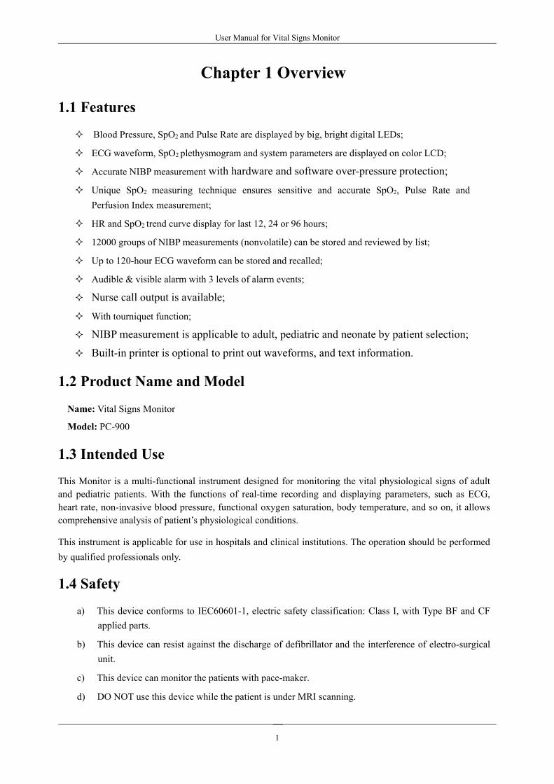
1.1 Features
Blood Pressure, SpO2 and Pulse Rate are displayed by big, bright digital LEDs;
ECG waveform, SpO2 plethysmogram and system parameters are displayed on color LCD;
Accurate NIBP measurement with hardware and software over-pressure protection;
Unique SpO2 measuring technique ensures sensitive and accurate SpO2, Pulse Rate andPerfusion Index measurement;
HR and SpO2 trend curve display for last 12, 24 or 96 hours;
12000 groups of NIBP measurements (nonvolatile) can be stored and reviewed by list;
Up to 120-hour ECG waveform can be stored and recalled;
Audible & visible alarm with 3 levels of alarm events;
Nurse call output is available;
With tourniquet function;
NIBP measurement is applicable to adult, pediatric and neonate by patient selection;
Built-in printer is optional to print out waveforms, and text information.
1.2 Product Name and Model
Name: Vital Signs Monitor
Model: PC-900
1.3 Intended Use
This Monitor is a multi-functional instrument designed for monitoring the vital physiological signs of adultand pediatric patients. With the functions of real-time recording and displaying parameters, such as ECG,heart rate, non-invasive blood pressure, functional oxygen saturation, body temperature, and so on, it allowscomprehensive analysis of patient’s physiological conditions.
This instrument is applicable for use in hospitals and clinical institutions. The operation should be performedby qualified professionals only.
1.4 Safety
a) This device conforms to IEC60601-1, electric safety classification: Class I, with Type BF and CFapplied parts.
b) This device can resist against the discharge of defibrillator and the interference of electro-surgicalunit.
c) This device can monitor the patients with pace-maker.
d) DO NOT use this device while the patient is under MRI scanning.

User Manual for Vital Signs Monitor
2
1.5 Symbols on the Monitor
Adult Patient Waveform Freeze
Pediatric Patient Pulse sync indicator
Neonatal Patient Setup Menu
NIBP Start/Cancel ~ AC Power
Alarm Silence DC Power
Print Type BF applied part
Up Type CF applied part withdefibrillator protection
OK Warning, refer to User Manual.
Down Equal potential terminal
ECG Lead Selection Nurse call output

User Manual for Vital Signs Monitor
3
Chapter 2 Operating Principle
2.1 Overall Structure
The overall structure of the monitor is shown in Fig. 2.1.
Figure 2.1
2.2 Conformation
PC-900 Vital Signs Monitor is module designed product; it consists of ECG/TEMP module (optional), NIBPmodule (optional), SpO2 module (optional), main control unit, printer module (optional), display panel, andpower supply block etc. and the related accessories for ECG, NIBP, SpO2 and Temperature measurement.
According to different needs, you can customize the module configuration by choosing necessarymodules. Therefore, your monitor may not have all the monitoring functions and accessories.
1. ECG/TEMP module measures ECG signal and detects heart rate with ECG lead wires and electrodes,it also measures temperature with temperature probe.
2. The SpO2 module detects and calculates pulse rate and oxygen saturation (SpO2), and providesplethysmogram and perfusion index as well.
3. The NIBP module performs the measurement of blood pressure by non-invasive way of oscillometrictechnology, including the diastolic, systolic and mean arterial pressure. The cuffs are designed foradult, pediatric and neonate respectively.
4. The main control unit is in charge of LED and LCD display, keyboard input, data storage, printingand networking function.

User Manual for Vital Signs Monitor
4
Chapter 3 Installation and Connection
3.1 Appearance
3.1.1 Front Panel
Figure 3.1 Front panel illustration
Description:1 Alarm indicator
Indicator Alarm Level Alarm Event
Red flashing High priority alarm Exceeding the limits, low battery voltage
Orange flashing Medium priority alarm Leads or probe off
Green light Normal

User Manual for Vital Signs Monitor
5
2 SYS: display systolic pressure value.
3 DIA: display diastolic pressure value.
4 MAP: When NIBP measurement mode is set to “manual” and “STAT”: Display mean arterialpressure or measuring time of the latest group of NIBP measurement; they will be displayedalternately. The format of NIBP measuring time is “hh:mm”. If the tourniquet is in use, the cuffpressure will be displayed here; When NIBP measurement mode is set to “AUTO”: Displayreal-time pressure value during measurement. Countdown time will be displayed in the MAP whenthe measurement finishes. Countdown time has two formats (>1 hour HH: mm; <1 hour mm: ss).
Note: two formats to display NIBP value: “×××mmHg” and “××.×kPa”. Refer to section “4.4.2 NIBPSetup” to set the unit of NIBP value; the conversion relation between “mmHg” and “kPa”:1mmHg=0.133kPa.
5 HR(priority indicator): if HR indicator is on, it indicates that the numerical value beside is HRmeasuring value;
6 Display HR or PR value: when the set of “Setup Menu→ System→priority” is “HR”, it shows HRvalue here preferentially; if the set is “PR”, PR value will be shown preferentially.
7 PR(priority indicator): if PR indicator is on, it indicates that the numerical value beside is pulserate value; Unit: “bpm (beats per minute)”.
If SpO2 and NIBP are monitoring at the same time, only the PR value measured through SpO2 probeis displayed here and the PR measuring by NIBP measurement is undergoing and recorded in NIBPlist.
8 SpO2: Display SpO2 value; Unit: “%”.
9 “ ”: Bar-graph of pulse intensity.
10 LCD panel
11 Pulse sync indicator patient category indicator: “ ” for adult; “ ” for pediatric; “ ” forneonate; Patient category is selected under sub-menu “Patient Info” within the setup menu.
12 Pulse sync indicator: Cardio-pulse/pulse sync indicator. When HR priority indicator is on, itsflashing is synchronized with heart beat; When PR priority indicator is on, its flashing issynchronized with pulse.
13 NIBP: start/cancel NIBP measurement.
14 Alarm silence key: Enable/disable alarm silence function. When the alarm silence indicatoron the left of keys is on, it means the system is in alarm silence status and it lasts this status for 2minutes. When finishing counting down, the system will resume normal alarm status automatically,if alarm event occurs at this time the alarm sound will be effective again.
DO NOT silence the audible alarm or decrease its volume if patient safety could becompromised.

User Manual for Vital Signs Monitor
6
15 Alarm silence indicator:When it is on, it indicates that the monitor stays in alarm silence status.
16 Print: the internal printer is optional, press this key to print the current measuring data;
17 Up: shift cursor forward/upward
18 OK: to confirm selection or modification
19 Down: shift cursor backward/downward
20 Display: short time pressing to shift LCD display modes; longtime pressing to enter into SetupMenu display screen.
21 Waveform Freeze: freeze the current displayed waveform.
22 ECG Lead Selection: select ECG leads among I, II, III, aVR, aVL, aVF and V.
23 ~:AC Power indicator
24 : DC Power indicator
AC Power indicator DC Power indicator Descriptions
Status
ON (green) ON (green) this device is using mains power supply
ON (green) ON (orange)this device is using mains power supply andthe battery is being recharged.
OFF ON (green) the battery is being used
OFF ON (orange, blinking)the battery is being used, but battery voltageis low, the beeper also gives warning.
ON (green) OFFthe battery is being recharged while thedevice is off
25 : Power button: Press power button for 3 seconds to start the monitor or shut off the monitor.
Note: Short time pressing power button for entering the Power Saving Mode screen, then according toyour need to make the device stay in the power saving mode or exit from power saving mode (thisfunction is optional and needs hardware support).
26 SpO2: SpO2 sensor connector
27 NIBP: NIBP hose connector
28 TEMP: TEMP probe connector
29 ECG: ECG cable connector
3.1.2 Side Panel
The built-in thermal printer is in the left panel. It is easy for user to print waveform and data.

User Manual for Vital Signs Monitor
7
3.1.3 Rear Panel
Figure 3.2 Rear Panel
Introduction to the rear panel:
1 Handle
2 Fan
3 Nameplate
CE mark
Serial number
Date of manufacture
Authorised representative in the European community
Manufacturer (including address and date)
Disposal of this device according to WEEE regulations
4 “FUSE T3.15 A”: Fuse holder. Fuse specification: T3.15AL/250VΦ5 20mm.
5 “AC100~240V” : AC power supply socket
6 Loudspeaker
7 Mounting hole for hanging the monitor
8 NET: serial communication port which is used to network with central monitoring system (optional);
9 Nurse-call connector
10 : Equipotential ground terminal

User Manual for Vital Signs Monitor
8
3.2 Installation
3.2.1 Opening the Package and Check
1. Open the package, take out the monitor accessories from the box carefully and place it in a safestable and easy to watch position.
2. Open the accompanying document to sort the accessories according to the packing list.
Inspect the monitor for any mechanical damages
Check all the accessories for any scratch or deformity, especially on connector, wire and probeparts
You can customize the module configuration by choosing necessary modules to meet your ownneeds. Therefore, your monitor may not have all the monitoring functions and accessories.
If in doubt, please contact the local dealer or our company in case of any problems. We are to offeryou the best solution for your satisfaction.
3.2.2 Connecting the Power Supply1. When powered by AC mains power supply:
Make sure that the AC power supply is 100-240VAC, 50/60Hz.
Use the power cable prepared by the manufacturer. Insert one end of it to the power port ofthe monitor and the other end to the grounded three-phase power jack.
To eliminate potential differences, the monitor has a separate connection to the equipotentialgrounding system. Connect one end of the provided ground cable to equipotential groundingport on the rear of the monitor, and connect the other end to one point of the equipotentialgrounding system.
Caution: ensure that the monitor is grounded correctly.After the supply mains has been interrupted when power switch remains in the “on” position and isrestored after a period of time that is longer than 30 seconds, the monitor will run by the lastsettings when restarting the monitor.
2. When powered by built-in battery
Caution: it’s better to recharge the battery after it is used up, the charging time should be13~15 hours long.
The provided battery of the monitor must be recharged after transportation or storage. So ifthe monitor is switch on without being connected to the AC power socket, it may not workproperly due to insufficient power supply.
3.2.3 Starting the Monitor
The system performs self-test and enters initial display after switching on the monitor, and the orange alarmindicator blinks to inform that the user can begin operating it.
Check all the applicable functions to make sure that the monitor works normally.
If the battery is applied please recharge it after using the monitor to ensure sufficient powerstorage. It will take minimal 8 hours to charge battery from depletion to 90% charge.

User Manual for Vital Signs Monitor
9
Do not use the device to monitor the patient if there are indications of damage or reminders of
error. Please contact the local dealer or our company.
It’s recommended to delay 1 minute to start it again.
3.3 Sensor Placement and Connection
3.3.1 ECG Cable Connection
ECG measurement is to collect the ECG signal via the ECG electrodes. Electrode connects the patient and the
lead. The lead connects the monitor. The locations of the electrodes are very important for obtaining
accurate ECG signals.
1. Connect the cable to the right-panel connector marked with the ECG icon.
2. Select electrodes to be used. Use only one type of electrode on the same patient to avoid variations
in electrical resistance. For ECG monitoring, it is strongly recommended to use silver/silver chloride
electrodes. When dissimilar metals are used for different electrodes, the electrodes may be subject
to large offset potentials due to polarization. Using dissimilar metals may also increase recovery
time after defibrillation.
3. Prepare the electrode sites according to the electrode manufacturer’s instructions.
4. Skin clean
Clean and dry-abrade skin to ensure low sensor impedance. Mild soap and Water is
recommended as a skin cleanser.
Note: Alcohol is not recommended as a skin cleanser; it leaves a film layer that may cause high
sensor impedance. If alcohol is used, ensure 30-second dry time.
Dry-abrading the skin gently with a dry wash cloth, gauze, or skin preparation product is helpful
to remove the non-conductive skin layer.
The symbol indicates that the cable accessories are designed to have special protection against
electric shocks, and is defibrillator proof.
The locations of the electrode are in the following Figure:
Figure 3.3 Electrode Location
Note: If skin rash or other unusual symptoms develop, remove electrodes from patient.
5. After starting the monitor, if the electrodes become loose or disconnected during monitoring, the
system will display “LEAD OFF” on the screen to alarm the operator.
It might not display ECG wave with 3 leads. The 5 leads should be used to have ECG wave.

User Manual for Vital Signs Monitor
10
6 The ECG leads and their corresponding locations are as follows:
Electrode connection 1
(IEC Standard)
Electrode connection 2
(AHA Standard) Electrode position on body
surface Color code
Label on lead wire connection
Color code Label on lead
wire connection
Red R White RA Right Arm: The intersection between the centerline of the right clavicle and Rib 2
Yellow L Black LA Left Arm: The intersection between the centerline of the left clavicle and Rib 2
Green F Red LL Left Leg: Left part of the upper abdomen
Black N/RF Green RL Right Leg: Right part of the upper abdomen
White C Brown V Any of the following location (C1-C6 or V1-V6) on chest
White/red C1 Brown V1 4th Intercostal (IC) space at right border of sternum
White/Yellow C2 Brown/Yellow V2 4th IC space at left border of sternum
White/Green C3 Brown/Green V3 Midway between V2 and V4
White/Brown
(blue)
C4 Brown/Blue V4 5th IC space on left midclavicular line
White/Black C5 Brown/Red V5 Left anterior axillary line at the horizontal level of V4
White/Purple C6 Brown/Purple V6 Left midaxillary line at the horizontal level of V4
Table 3-1
Safety Instructions for ECG Monitoring
Use the same type electrode on a patient. If skin rash or other unusual symptom occurs, remove
electrodes from patient. Do not attach electrodes on the patient with an inflammation of the skin
or scores on skin.
PC-900 Vital Signs Monitor can only be equipped with ECG leads provided by our company; using
ECG leads supplied by other companies may cause improper performance or poor protection
while using defibrillator.
Electric parts of electrodes, leads and cable are forbidden to contact any other conductive parts
(including ground).

User Manual for Vital Signs Monitor
11
Figure 3.4 Cuff Placement
PC-900 Vital Signs Monitor can resist against defibrillator and electrosurgical unit. Readings may be
inaccurate for a short time after or during using defibrillator or electrosurgical unit.
Transient caused by cable circuitry blocks while monitoring may be similar to the real heartbeat
waveform, as a result resistance heart rate alarm rings. If you put the electrodes and cable in
proper places according to this manual’s instructions and the instructions for using electrode, the
chance of this transient occurring will be decreased.
Besides the improper connection with electrosurgical unit may cause burns, the monitor may be
damaged or arouse deviations of measurement. You can take some steps to avoid this situation,
such as do NOT use small ECG electrodes, choosing the position which is far away from the
estimated Hertzian waves route, using larger electrosurgical return electrodes and connecting with
the patient properly.
ECG leads may be damaged while using defibrillator. If the leads are used again, please do the
functional check first.
When removing the ECG cable, hold the head of the connector and pull it out.
When the monitor is inoperable due to an overload or saturation of any part of the amplifier, it
will prompt “Lead off” to remind operator.
No predictable hazard will be caused by the summation of leakage currents when several item of
monitor are interconnected.
3.3.2 Blood Pressure Cuff Connection
1. Connect the cable to the right-panel connector marked with the NIBP icon.
2. Unveil and wrap the cuff around patient’s upper arm.
Requirements of the cuff:
1) Appropriate cuff should be selected according to the age of the subject. Its width should be 2/3 of the
length of the upper arm. The cuff inflation part should be long enough to permit wrapping 50-80% of
the limb concerned.
Note: The size of the cuff selected should suit the subjects while measuring.
When putting on the cuff, unveil and wrap it around the upper arm evenly to appropriate
tightness.
2) Remember to empty the residual air in the cuff before the measurement is commenced.
3) Locate the cuff in such a way that the “φ” mark is at a location where the clearest pulsation of
brachial artery is observed.
4) The cuff should be tightened to a degree where insertion of one finger is allowed.
5) The lower end of the cuff should be 2cm above the elbow joint.

User Manual for Vital Signs Monitor
12
Pressure Accuracy VerificationPressure Accuracy Verification is a function to inspect the accuracy of pressure measurement by the NIBPmodule inside the device. Technician or equipment manager should do pressure accuracy verificationevery half year or year in order to check if the pressure measurement still conforms to the requirement ofproduct performance. If the deviation is beyond the declared specification, it is permitted to return it tofactory for repair or calibration.Before verification, please connect the monitor to a standard pressure meter as the referenceequipment like a mercury pressure meter
Figure 3.5 Connection of Pressure calibration fixtureMode 1: The inflation can be activated by Monitor so the pressure will increase automatically untilit exceeds the limit value specified in table A. This pressure limit value depends on the patient typeselection as shown in table A:
Adult 240mmHg
Child 200mmHg
Neonate 120mmHgTable A
During the inflation, the Monitor will close the deflating valve, and the pressure value will be shownduring the process. If there is no manual deflation operation, the pressure will persist until deflationby manual operation, so it is necessary to use a manual valve for doing adequate deflation in severalsteps to verify the pressure accuracy in the full scale of measurement range.Mode 2: No automatic inflation by Monitor during the pressure accuracy verification.Increase the pressure manually by the pumping balloon, and the verification can be done by applyingdifferent pressure value manually. If the increased pressure exceeds the given limit as shown in tableB, the Monitor will deflate automatically because of over-pressure protection.

User Manual for Vital Signs Monitor
13
Adult 300mmHg
Child 240mmHg
Neonate 140mmHg
Table BAfter the verification, do press the button again to return to normal working mode, thencontinue other operation, or the NIBP key will be invalid.
Pressure accuracy verification must be operated by technician or equipment manager. Doctoror nurse is not allowed to do the verification, it is very dangerous especially when the pressurecuff is still on patients.
Air Leakage CheckIn order to avoid significant error of blood pressure measurement or even no measurement result causedby air leakage in the pneumatic system including the cuff during measuring, it is recommended to check ifthere is leak in the pneumatic system as well.
Please remove the cuff from patient while performing the leakage check.
Safety Instructions for NIBPMonitoring
When taking the measurement of a pediatric or an infant or neonate’s (less than 10 years old)blood pressure, do NOT operate in the adult mode. The high inflation pressure may causelesion or even body putrescence.
It is recommended to take the blood pressure measurement manually. Automaticmeasurement should be used at the presence of a doctor/nurse.
NIBP monitoring is prohibited to those who have severe hemorrhagic tendency or with sicklecell disease, or partial bleeding will appear.
Pay attention to the color and sensitivity of the limb when measuring NIBP; make sure theblood circulation is not blocked. If blocked, the limb will discolor, please stop measuring orremove the cuff to other positions. Doctor should examine this timely.
Confirm your patient category (adult, pediatric or neonate) before measurement.
Do NOT bind NIBP cuff on limbs with transfusion tube or intubations or skin lesion area,otherwise, damages may be caused to the limbs.
If the time of the automatic pattern noninvasive blood pressure measurement is too long, thebody connected with the cuff will possibly occur the purpura, lack the blood and theneuralgia. In order to protect patient, it is requested to inspect the luster, the warmth and thesensitivity of the body far-end frequently. Once observes any abnormity, please immediatelystop the blood pressure measurement.
The patient should lie on the back so that the cuff and the heart are in a horizontal positionand the most accurate measure is taken. Other postures may lead to inaccurate measurement.
Do not speak or move before or during the measurement. Ensure that the cuff will not be hitor touched by other objects.

User Manual for Vital Signs Monitor
14
The measures should be taken at appropriate intervals. Continuous measurement at too shortintervals may lead to pressed arm, reduced blood flow and lower blood pressure, andresulting inaccurate measure of blood pressure. It is recommended to take measurement atintervals of more than two minutes.
When an adult is monitored, the machine may fail in giving the blood pressure measure if theinfant mode is selected.
Prior to use of the cuff, empty the cuff until there is no residual air inside it to ensureaccurate measurement.
Do NOT twist the cuff tube or put heavy things on it.
When unplugging the cuff, hold the head of the connector and pull it out.
The symbol indicates that the cable and accessories are designed to have special protection against
electric shocks, and is defibrillator proof.
3.3.3 SpO2 Sensor Connection
SpO2 sensor is a very delicate part. Please follow the steps and procedures in operating it. Failure to operate itcorrectly can cause damage to the SpO2 sensor.
Operation procedure:1. Connect the SpO2 sensor to the connector labeled “SpO2”. When unplugging the probe, be
sure to hold the head of the connector and pull it out.
2. If the finger clip SpO2 sensor is used, insert one finger into the sensor (index finger, middlefinger or ring finger with short nail length) as shown in the figure below.
Figure 3.6 Finger clip SpO2 sensor placementWhen selecting a sensor, consider the patient’s category, adequacy of perfusion, availability of probe site andanticipated monitoring duration. Use only SpO2 probes provided by our company with this monitor. Read thefollowing table for SpO2 probe information. Refer to Chapter 11.5 for the detailed instructions of each SpO2probe.
SpO2 Probe Patient Category
SpO2 Finger clip Sensor (reusable) Pediatric
SpO2 Finger rubber Sensor(reusable) Adult
SpO2 Finger clip Sensor(reusable) Adult

User Manual for Vital Signs Monitor
15
3. If the neonate SpO2 sensor is used, please follow Figure 3.7 to connect.
Figure 3.7 Neonate SpO2 sensor placementHigh ambient light sources such as surgical lights (especially those with a xenon light source), bilirubinlamps, fluorescent lights, infrared heating lamps, and direct sunlight can interfere with the performance of anSpO2 sensor. To prevent interference from ambient light, ensure that the sensor is properly applied, and coverthe sensor site with opaque material.Failure to take this action in high ambient light conditions may result in inaccurate measurements.If patient movement presents a problem, verify that the sensor is properly and securely applied; move thesensor to a less active site; use an adhesive sensor that tolerates some patient motion; or use a new sensorwith fresh adhesive backing.For reusable sensors, follow the sensor directions for use for cleaning and reuse. For single-patient usesensors, use a new sensor for each patient. Do not sterilize any sensor by irradiation, steam, or ethyleneoxide.Safety Introductions for SpO2 Monitoring
Continuous use of SpO2 sensor may result in discomfort or pain, especially for those withmicrocirculatory problem. It is recommended that the sensor should NOT be applied to thesame place for over two hours, change the measuring site periodically if necessary.SpO2 measuring position must be examined more carefully for some special patient. Do NOTplace the SpO2 sensor on the finger with edema or fragile tissue.If sterile packaging of SpO2 sensor is damaged, do not use it any more.Check the SpO2 sensor and cable before use. Do NOT use the damaged SpO2 sensor.When the temperature of SpO2 sensor is abnormal, do not use it any more.
Please do not allow the cable to be twisted or bended.
Do NOT put the SpO2 sensor and pressure cuff on the same limb, otherwise the NIBPmeasuring will affect SpO2 measuring and cause the alarm error.
Using nail polisher or other cosmetic product on the nail may affect the accuracy ofmeasurement.
The fingernail should be of normal length.
The SpO2 sensor can not be immerged into water, liquor or cleanser completely, because thesensor has no capability to resist the harmful ingress of water
Y type sensor
Sensor adapter: wrapper

User Manual for Vital Signs Monitor
16
3.3.4 TEMPTransducer Connection
Connecting methods:
1. Attach the transducers to the patient firmly;
2. Connect the cable to TEMP probe connector in the front panel.
Note: When unplugging the probe, be sure to hold the head of the connector and pull it out.
3.3.5 Loading printing paper
Operation procedures for loading printing paper:
1. Press both “OPEN” notches with force on printer shield with two thumbs to open it.
2. Move the tab of rubber roller lock at the left 90°upwards to unlock it, refer to the followingfigure with mark①.
3. Cut one end of the paper into triangle, and load the paper from the underside of the rubber roller.
4. Turn the roller clockwise to get the paper rolled, and put the paper roll into the compartment.
5. Pull the paper out of paper slot on the shield.
6. Move the tab of the rubber roller lock 90° downwards to lock it.
7. Put the shield back in position and secure it.
Operation procedures for taking out printing paper roll:
1~2 steps are the same with the 1~2 steps mentioned above for loading printing paper.
3. Roll the loading roller anti-clockwise and pull the paper out.
4~5 steps are the same with the 6~7 steps mentioned above for loading printing paper.
Figure 3.8 Loading and taking out printing paper
P8 printer may be used due to the different configuration.P8 printer operation instruction:
Power indicator: green light shows the power is on, while the monitor is out of power, the green light is off.
Error indicator: red light is constant which shows the printer is out of paper, or the printing paper does notinstall well. When the printer installs normally, the red light is off.

User Manual for Vital Signs Monitor
17
Figure 3.9 P8 printerLoading printing paper:
Step 1: press and hold down the cartridge button to open the paper cartridge;
Step 2: Install the paper to the printer properly, pull the paper out of the printer for 2 cm, as shown in figure3.10.
Step 3: Close the printer cover along the direction of arrow, as shown in figure 3.10.
Figure 3.10 printing paper
Power IndicatorOpen button
Error Indicator
Paper cartridge

User Manual for Vital Signs Monitor
18
3.3.6 Battery Installation
1. Ensure that the monitor is not connected to AC power supply and the monitor is turned off.
2. Open the battery cover and place the battery in the direction as shown in Fig. 3.11 to insert thebattery into any one of battery compartments. Do not insert battery with their polarities reversed.
3. Move the battery baffle to secure battery.
4. Close the battery cover.
Figure 3.11 Battery InstallationNote:
Do not insert battery terminal with its polarities reversed, or the monitor can not be started.Please take out the battery before transport or storage.
Underside view
User Manual for Vital Signs Monitor
19
Chapter 4 Operations
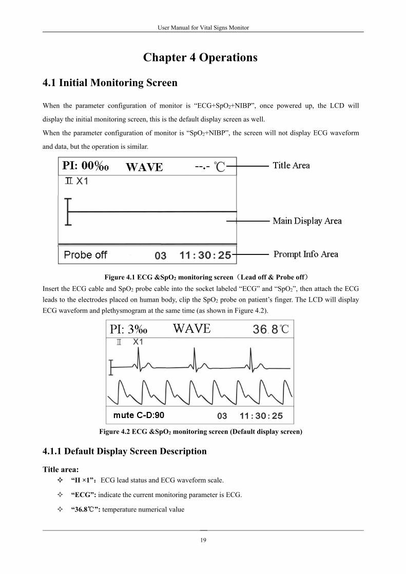
4.1 Initial Monitoring Screen
When the parameter configuration of monitor is “ECG+SpO2+NIBP”, once powered up, the LCD will
display the initial monitoring screen, this is the default display screen as well.
When the parameter configuration of monitor is “SpO2+NIBP”, the screen will not display ECG waveform
and data, but the operation is similar.
Figure 4.1 ECG &SpO2 monitoring screen(Lead off & Probe off)Insert the ECG cable and SpO2 probe cable into the socket labeled “ECG” and “SpO2”, then attach the ECGleads to the electrodes placed on human body, clip the SpO2 probe on patient’s finger. The LCD will displayECG waveform and plethysmogram at the same time (as shown in Figure 4.2).
Figure 4.2 ECG &SpO2 monitoring screen (Default display screen)
4.1.1 Default Display Screen Description
Title area:“II ×1”:ECG lead status and ECG waveform scale.
“ECG”: indicate the current monitoring parameter is ECG.
“36.8”: temperature numerical value

User Manual for Vital Signs Monitor
20
“PI: 3‰”: the perfusion index is 3‰; it displays only when “Setup Menu→SpO2→PI Display” isset as “ON”.
Note: PI display function is optional and it needs hardware support.
Main display area:
When ECG leads is attached on the patient and connected to the monitor well, ECG waveform willbe displayed in the main display area. Meanwhile HR value will show on digital LED.
When SpO2 probe is clipped on the patient and connected to the monitor well, SpO2plethysmogram will be displayed in the main display area.
Prompt Info:
Status or event indication segment:
This segment will display the ECG leads status, probe status, alarm silence counting-down timer,automatic NIBP measurement counting-down timer, over limit warning and other error messagesfor technical warning. If more than one event occurs or more status appears, the indication messagewill be displayed alternately at this segment.
“NIBP C-D: XXX”: the counting-down timer of NIBP measurement is XXX seconds. This promptmessage appears only when the NIBP measuring mode is set as “AUTO X”.
“mute C-D: XXX”: the counting-down timer of alarm silence is XXX seconds. This promptmessage appears only when the alarm silence is enabled.
Patient ID segment:
“03”: Patient ID number.
Real time clock segment:
“11:30:25”: the current time.
4.1.2 Operation Instructions
“ ” key: select ECG lead. When ECG is monitored, press this key to switch the ECG leadamongⅠ,Ⅱ,Ⅲ, aVR, aVL, aVF and V.
“ ” key: freeze ECG waveform or Plethysmogram on the screen.
“ ” key: shift display mode among 5 display views: ECG & SpO2 monitoring screen (defaultscreen), ECG monitoring screen, trend graph screen, NIBP list screen and ECG waveform recallscreen.
“ ” key: print ECG waveform. Press it again to stop printing.
“ ” key: start/cancel NIBP measurement.
“ ”/ “ ”key:change ECG waveform scale.

User Manual for Vital Signs Monitor
21
“ ” key: short press this key (about 1 second) to turn on or turn off the alarm sound
temporarily; Long time press it to enter into the alarm setup shortcut menu as shown in figure 4.3.If not turn off “ECG Lead off” and “SpO2 Probe off” manually after alarm lasts for 5 minutes,system will resume alarm silence status.
Figure 4.3 Alarm setup shortcut screen
Alarm setup operation description:
1. Press “” key or “” key to move cursor to select parameter.
2. Press “” key to confirm and enter into corresponding alarm parameter setup screen; Press “” key
or “” key again to turn off corresponding lead off alarm.
3. Press “ ” to exist from Setup Menu Screen.

User Manual for Vital Signs Monitor
22
4.2 ECG Monitoring Screen
Short pressing “ Display” key to shift the screen view to ECG monitoring screen, as shown in Figure 4.4.
Figure 4.4 ECG Monitoring Screen
Note: if you need to store the measuring data, please set the option of “store” as “on” on ECG TEMP settingscreen.
4.2.1 Display Screen DescriptionTitle area:
“Ⅱ ×1”: ECG lead status and ECG waveform scale.
“ECG”: indicate the current monitoring parameter is ECG.
“36.8”: temperature numerical value
Main display area:When ECG leads is attached on the patient and connected to the monitor well, ECG waveform willbe displayed in the main display area.
Prompt Info:“Probe off”: the SpO2 sensor is disconnected from the monitor or off from the patient.
“03”: Patient ID number.
“11:30:25”: the current time.
4.2.2 Operation Instructions
“ ” key: select ECG lead. When ECG is monitored, press this key to switch the ECG leadamongⅠ,Ⅱ,Ⅲ, aVR, aVL, aVF and V.
“ ” key: freeze ECG waveform or Plethysmogram on the screen.
“ ” key: shift display mode.
“ ” key: print ECG waveform. Press it again to stop printing.
“ ” key: start/cancel NIBP measurement.
“ ” key: Alarm silence switch, press it to enable/disable alarm silence.
“ ”/ “ ”key:change ECG waveform scale.

User Manual for Vital Signs Monitor
23
4.3 Trend Graph Display
Short pressing “ Display” key to shift the screen view to trend graph display screen, as shown in Figure4.5.
Figure 4.5 Trend Graph
4.3.1 Screen Description
“12 hours”: the trend length of trend graph; three options: “12”, “24” or “96” hours; when theselection is 12 hours, the upper trend graph will display SpO2 trend curve for last 12 hours.
“cursor on”: enable the display of cursor on trend graph, i.e. the vertical cursor line displayed in trendgraph, so the user can move the cursor to inspect the SpO2 value at the given time.
“SpO2”: indicate that the trend graph beside it is SpO2 trend. Let the cursor stay here and press“”key to confirm, then press “” key or “” key again to select trend graph type:
“SpO2”: SpO2 trend graph
“HR”: HR trend graph
4.3.2 Operation Instructions
1. Press “” key or “” key to highlight “trend length” or “cursor on” selection.
2. Press “” key to confirm.3. Press “” key or “” key again to select value of trend length (12/24/96 hours) if the selecting boxstays in “trend length” option, or to move the cursor if the selecting box stays in “cursor on” option.
Instructions for viewing the trend curve:
Select “cursor on” and press “” key to confirm, and “cursor on” becomes “cursor off” , then youcan press “” key or “” key to move the vertical cursor, the list box below will displaySpO2/HR value and the time value at the point where the cursor stays. Move cursor back and forththis way, you can view the SpO2/HR trend (12/24/96 hours long). Press “” key again to exit trendviewing.When pressing “” key or “” key to move cursor, the moving step is variable. The rule is thatthe initial step is 1 point, after pressing “” or “” key towards the same direction for 5 times,the step becomes 5 points, and with 5 more pressing the step becomes 10, then 20. No matter what
Trend length
Trend graph

User Manual for Vital Signs Monitor
24
step is, as long as you press “” or “” key towards the other direction, the step becomes 1 andtowards the other direction.
4. Press:
“ ” key: press this key to shift to next display view.
“ ” key: Press it to print the current displayed trend graph.
“ ” key: start/cancel NIBP measurement
“ ” key: alarm silence switch; press it to enable/disable alarm silence.
4.4 NIBP List ScreenShort pressing “ Display” key to shift the screen to NIBP List screen, as shown in Figure 4.6.
Figure 4.6 NIBP ListThe first column is the date, the second column is NIBP measuring time, the third column is NIBP value, andthe fourth column is pulse rate (measured by NIBP module). Up to 12000 groups of nonvolatile data can bestored in the monitor. “SYS/DIA/MAP” indicates the value of “systolic pressure/diastolic pressure/meanarterial pressure”.
4.4.1 Operation Instructions
On NIBP List screen, if NIBP measurement is more than 8 groups, press “” key or “” key to turn toprevious/next page for view other measurement values. If NIBP measurement is not more than 8 groups, thekeys “”or “” are not effective.
“ ” key: press this key to shift to next display view.
“ ” key: print NIBP list.
“ ” key: start/cancel measuring NIBP.
“ ” key: alarm silence switch; press it to enable/disable alarm silence.

User Manual for Vital Signs Monitor
25
4.5 SpO2 List ScreenShort pressing “ Display” key to shift the screen to SpO2 List screen, as shown in Figure 4.7
Figure 4.7 SpO2 List
The first column is the date, the second column is SpO2 measuring time, the third column is SpO2 value, andthe fourth column is pulse rate. Up to 2000 groups data which are lately measured can be stored in themonitor when it is out of power..
4.5.1 Operation Instructions
On SpO2 List screen, if SpO2 value measurement is more than 8 groups, press “” key or “” key to turn toprevious/next page for view other measurement values. If SpO2 measurement is not more than 8 groups, thekeys “”or “” are not effective.
“ ” key: short press this key to shift to next display view. Long press to enter the screen ofEmpty history records, the user can delete all SpO2 records according to prompt.
“ ” key: print SpO2 list if the monitor equips with built-in printer, press this key again to stop
printing
“ ” key: start/cancel measuring NIBP.
“ ” key: alarm silence switch; press it to enable/disable alarm silence.
4.6 ECG Recall ScreenShort pressing “ Display” key to shift the screen to Default ECG Recall screen, as shown in Figure 4.8.On this screen, the latest 120-hour ECG data stored in monitor can be reviewed.
Figure 4.8 Default ECG Recall Screen

User Manual for Vital Signs Monitor
26
4.6.1 Operation Instructions
1. Press “” key to confirm “view”.2. Then press “” key or “” key to shift yellow selecting box to choose a record. After pressing “”key to confirm, its recorded ECG waveform will display on screen.
Figure 4.9 Recalled ECGWaveform3. Press “” key or “” key to turn to the previous/next page to view recalled ECG waveform.4. Press “” to back to Default ECG Recall screen.
Note: If the setting of “store” on ECG TEMP setting screen is “off”, thereafter the ECG data measured willnot be stored.
4.7 Setup Menu Screen
At any display view screen, long time press “ Display” key to shift the screen to Setup Menu screen, asshown in Figure 4.10. All the functional parameters of the system can be set through Setup Menu.
Figure 4.10 Setup Menu ScreenThere are 8 functional groups for setting parameters: “ECG TEMP, SpO2, NIBP, Nurse Call, System, PatientInfo, Date/Time and Default” on the Setup Menu Screen.
1. Press“” key or “” key to shift cursor to corresponding functional group setting.
2. Pres “” key to confirm and enter into corresponding functional parameter setup screen.
3. Pres “ ” key under the setup menu will print ECG waveform.

User Manual for Vital Signs Monitor
27
4. Press “ ” to exist from Setup Menu Screen.
At Setup Menu Screen or its submenu screen, when pressing “ ” key, the default display screenwill be printed.
The following will cover each functional parameter’s setting up.
Note: If you disable Hi and Lo limit alarm function of parameter monitoring, all the alarms related toits parameter monitoring will be disabled as well.
4.7.1 ECG and Temperature Setup
Figure 4.11 ECG/TEMP Setup Screen
Screen Description:“Lead”: ECG lead selection:Ⅰ,Ⅱ,Ⅲ, AVR, AVL, AVF or V.
“Gain”: ECG waveform scale:
“×1/4”-Waveform scaled with 1/4 of the base gain
“×1/2”-Waveform scaled with half of the base gain
“×1”-Waveform scaled with base gain
“×2”-Waveform scaled with twice of the base gain
“1mV”: generating internal 1mV calibration signal. This signal is used to test the function of themachine. It is not used during normal operation. The default set is off.
“Enhancement mode”: the switch of ECG enhancement mode.
“HR ”: HRalarm switch; “ ” indicates HR alarm is on; “ ” indicates HR alarm is off.
“HR Hi/Lo”: high/low limit of HR alarm.
“TEMP ”: temperature alarm switch; “ ” indicates temperature alarm is on; “ ” indicatestemperature alarm is off.
“TEMPHi/Lo”: high/low limit of temperature alarm.
“Unit”: body temperature unit. Two options: “” or “”. Conversion relation: 1= (X1.8) +32.
User Manual for Vital Signs Monitor
28
“Store”: decide whether to store ECG data or not. If your selection is “off”, thereafter the ECG datameasured will not be stored.
“T probe”: the type of temperature probe “KRK”.
4.7.2 SpO2 Setup
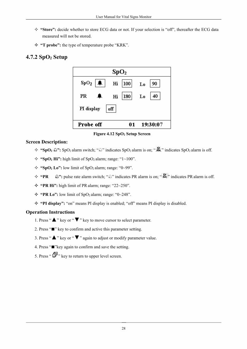
Figure 4.12 SpO2 Setup Screen
Screen Description:“SpO2 ”: SpO2 alarm switch; “ ” indicates SpO2 alarm is on; “ ” indicates SpO2 alarm is off.
“SpO2 Hi”: high limit of SpO2 alarm; range: “1~100”.
“SpO2 Lo”: low limit of SpO2 alarm; range: “0~99”.
“PR ”: pulse rate alarm switch; “ ” indicates PR alarm is on; “ ” indicates PR alarm is off.
“PR Hi”: high limit of PR alarm; range: “22~250”.
“PR Lo”: low limit of SpO2 alarm; range: “0~248”.
“PI display”: “on” means PI display is enabled; “off” means PI display is disabled.
Operation Instructions1. Press “” key or “” key to move cursor to select parameter.
2. Press “” key to confirm and active this parameter setting.3. Press “” key or “” again to adjust or modify parameter value.
4. Press “”key again to confirm and save the setting.5. Press “ ” key to return to upper level screen.
User Manual for Vital Signs Monitor
29
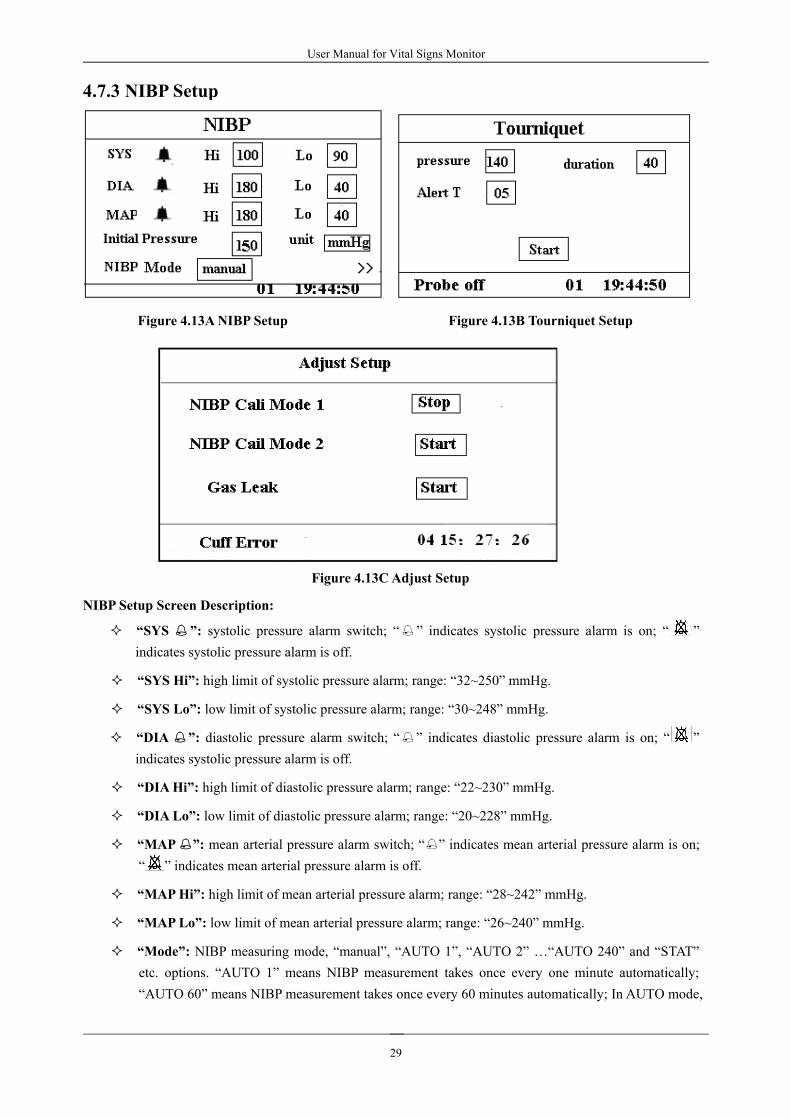
4.7.3 NIBP Setup
Figure 4.13ANIBP Setup Figure 4.13B Tourniquet Setup
Figure 4.13CAdjust Setup
NIBP Setup Screen Description:
“SYS ”: systolic pressure alarm switch; “ ” indicates systolic pressure alarm is on; “ ”indicates systolic pressure alarm is off.
“SYS Hi”: high limit of systolic pressure alarm; range: “32~250” mmHg.
“SYS Lo”: low limit of systolic pressure alarm; range: “30~248” mmHg.
“DIA ”: diastolic pressure alarm switch; “ ” indicates diastolic pressure alarm is on; “ ”indicates systolic pressure alarm is off.
“DIAHi”: high limit of diastolic pressure alarm; range: “22~230” mmHg.
“DIA Lo”: low limit of diastolic pressure alarm; range: “20~228” mmHg.
“MAP ”: mean arterial pressure alarm switch; “ ” indicates mean arterial pressure alarm is on;“ ” indicates mean arterial pressure alarm is off.
“MAPHi”: high limit of mean arterial pressure alarm; range: “28~242” mmHg.
“MAP Lo”: low limit of mean arterial pressure alarm; range: “26~240” mmHg.
“Mode”: NIBP measuring mode, “manual”, “AUTO 1”, “AUTO 2” …“AUTO 240” and “STAT”etc. options. “AUTO 1” means NIBP measurement takes once every one minute automatically;“AUTO 60” means NIBP measurement takes once every 60 minutes automatically; In AUTO mode,

User Manual for Vital Signs Monitor
30
the counting-down timer is displayed in the “Prompt Info” area.
“Initial pressure setup”: Cuff pre-inflation pressure value is default
for neonates: pre-inflation range: 60~80mmHg, default value: “70” mmHg;
for infants: pre-inflation range: 80~140 mmHg, default value: “100” mmHg;
for adults: pre-inflation range: 80~200mmHg, default value: “150” mmHg.
Note: In order to avoid inappropriate initial pressure value to do harm to patients, pre-inflationpressure value will resume the default value when measurement mode shifts or changing patienttype or rebuilding patients’ files. .
“unit”: unit of the blood pressure value;
“mmHg” or “kPa” can be selected. Conversion: 1kPa=7.5mmHg.
“>>”: Page down icon. When cursor stays in the “unit” filed, press “” key to enter TourniquetSetup.
Tourniquet Setup Screen Description:
“Pressure”: when you use Tourniquet function, you need to preset a cuff pressure for hemostasia.The pressure is adjustable, and its adjusting limit is different for different patient category:
for neonates: preset range: 70~100mmHg, default value: “90” mmHg;
for infants: preset range: 80~130 mmHg, default value: “110” mmHg;
for adults: preset range: 80~180mmHg, default value: “140” mmHg.
If the pressure drops down slowly under 10mmHg compared with the preset value due to little airleakage in the pneumatic system when time passes by, the monitor will re-inflate to maintain thecuff pressure close to the preset pressure value.
Note: the unit of cuff pressure is the same with the NIBP unit in NIBP Setup.
“Duration”: After presetting the cuff pressure, you need to set the time period for maintaining thepreset pressure after inflation. “5, 6, 7,…120” minutes adjustable. The default value is “40” minutes.
If the set value is “xx” minutes, the monitor will count down from “xx” minutes automaticallywhen starting cuff inflation. When time is up, it will deflate automatically.
“Alert T”: the alert time for reminding user that the operation of tourniquet is going to be end afterthis time period. 1 to 60 minutes adjusting range with 1 minute step, the default value is “5” minutes.If the set value is “xx” minutes, the monitor will produce alarm sound until ending deflation whencounting down time reaches to “xx” minutes. The alarm type is high priority alarm. (For example:the duration is 40 minutes, the alert time is 5 minutes, the alarm will ring for prompt when theduration counting down to 5 minutes. The Prompt Info area starts to prompt: TOUR C-D 300seconds. )
“Start”: shift cursor to “Start” and press “” key, “Start” becomes “Stop” and meanwhile the bloodcuff starts being inflated; Pressing “Stop” button can stop using this function. After deflation, it willchange to “Start” again.
NIBP Calibration Setup Descriptions:
NIBP Cali Mode 1: Inflating the Pump. Move the cursor to NIBP Cali Mode 1”Start” button, click
the OK button to begin the NIBP calibration. (Meanwhile, the “Start” shifts to “Stop”, after the

User Manual for Vital Signs Monitor
31
calibration the “Stop” shifts to “Start”)
NIBP Cali Mode 2:Receiving the exterior pressure. The exterior pressure source pressurize to the
module to proceed the pressure calibration. Move the cursor to NIBP calibration mode 2”Start” button,
click the OK button to begin the NIBP calibration.(Meanwhile, the “Start” shifts to “Stop”, after the
calibration the “Stop” shifts to “ Start”)
Gas leak: Move the cursor to Gas leak ”Start” button, click the OK button, the pump inflates to
certain pressure and then the valve will be closed for leak detection for ten seconds, then the blood
pressure module will deflate automatically and the screen displays measurements.
The NIBP calibration and Gas leak detection can only be carried on when the NIBP measurement isset to mode “Manual”.
Other buttons are disabled except “” OK button and “ ” Power button during NIBP calibration
and Gas leak detection.
Make sure the “” OK button is off after the test, or the user could not do other operations.
NIBPMode Setup Shortcut Screen Descriptions:
In waveform display screen or trend graphic screen or NIBP list screen longtime press “ ”key about
3 seconds can enter into the screen shown in Figure 4.13D. Please refer to “NIBP Setup Screen
Description” for more detailed information.
Figure 4.13D NIBPMode Setup Shortcut Screen

User Manual for Vital Signs Monitor
32
4.7.4 Nurse Call
Figure 4.14 Nurse Call Setup Screen
Screen Description:“Output level”: two options “low” or “high” output levels are available.
When the calling system in hospital works in “Normal Open” mode, “low level” should be selected.
When the calling system in hospital works in “Normal Close” mode, “high level” should be selected“Source”: three kinds of alarm sources can trig the nurse call: high level alarm, medium level alarmand low level alarm (multi-optional). If you don’t make choice, nurse call signal will not be sent out.
“Duration”: two options “pulse” or “continuous” output modes are available;
“continuous”: the continuous mode of output means the nurse call signal will keep until the selectedalarm source(es) disappear, i.e. the signal will last from starting alarm to stopping alarm.
“pulse”: the output nurse call signal is pulse signal which lasts for 1 second. When several alarmsoccur at the same time, only one pulse signal will be sent out.
Note: Nurse Call function can not be regarded as main alarm notice method, please do not
entirely relay on it. You should combine parameter values with alarm level and patient’s clinical
behavior and symptom to determine patient’s status.
4.7.5 System Setup
Figure 4.15 System Setup Screen

User Manual for Vital Signs Monitor
33
Screen Description:“Volume”: set beeper volume, “1~7” level adjustable, the factory default is 03. It is recommendedthat the alarm volume shouldn’t be adjusted lower than the factory default value unless the nursingpersonnel keeps close attention and surveillance on the patients and the device at all times.
“key beep”: to turn on/off key beep;
“Language”: language selection. “ENG” for English.
“priority”: priority of “PR” value or “HR” value display. The default set is “HR”.
“care mode”: “Demo” shows the demo waveforms and data. In the demo state, all the signals anddata are generated from the monitor for demonstration and testing purpose. When the mode “Demo” isselected, the user can test whether the visual and audible alarm system runs normally by raising orlowering the alarm limit to trigger the monitor to alarm.
“Real” shows the real time waveform, i.e. normal monitoring status;
BT sound: adjust the volume of pulse beeping sound. “0~7” level adjustable. “0” means switching offthe sound.
4.7.6 Patient Info
Figure 4.16 Patient Info Screen
Screen Description:“ID”: change or set current patient’s ID number, 0~100 adjustable;
“category”: change or set the category of current patient; three options “adult” ,“pediatric” and“neonate”, the default is “adult”.
Note: If the patient ID is changed, the history data (except NIBP list) will be cleared, that means SpO2trend graph and HR trend graph will become empty.
User Manual for Vital Signs Monitor
34
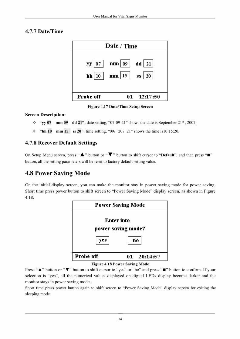
4.7.7 Date/Time
Figure 4.17 Data/Time Setup Screen
Screen Description:“yy 07 mm 09 dd 21”: date setting, “07-09-21” shows the date is September 21st , 2007.
“hh 10 mm 15 ss 20”: time setting, “09:20:21” shows the time is10:15:20.
4.7.8 Recover Default Settings
On Setup Menu screen, press “” button or “” button to shift cursor to “Default”, and then press “”button, all the setting parameters will be reset to factory default setting value.
4.8 Power Saving Mode
On the initial display screen, you can make the monitor stay in power saving mode for power saving.Short time press power button to shift screen to “Power Saving Mode” display screen, as shown in Figure4.18.
Figure 4.18 Power Saving ModePress “” button or “” button to shift cursor to “yes” or “no” and press “” button to confirm. If yourselection is “yes”, all the numerical values displayed on digital LEDs display become darker and themonitor stays in power saving mode.Short time press power button again to shift screen to “Power Saving Mode” display screen for exiting thesleeping mode.

User Manual for Vital Signs Monitor
35
Chapter 5 Alarm
5.1 Alarm Priority
High Priority:
TOUR C-D:XXX secondsPR Over limitSpO2 over limitSYS over limitDIA Over limitMAP Over limitNIBP error 1#NIBP error 2#NIBP error 3#NIBP error 4#NIBP error 5#Air leakCuff errorNIBP over rangeOver motionOver pressureNIBP timeoutMedium Priority:
Probe Off
5.2 Alarm modes
When an alarm occurs, the monitor responds with visual alarm indications (which are shown by two ways:
alarm indicator and alarm message description) and audible alarm indications.
Visual Alarm Indicators
The flashing rates for the three categories of alarms are shown in the table below.
Indicator Color Alarm Category Flashing Rate
Red flashing High priority alarm 2 Hz
Yellow flashing Medium priority alarm 0.5 Hz
Yellow light Low priority alarm Constant(on)(non-flashing)
Table 5.1
Refer to Chapter 11.2 Alarm Information for detailed alarm message descriptions.

User Manual for Vital Signs Monitor
36
Audible Alarm Indications
The audible alarm has different tone pitch and on-off beep patterns for each priority category. These are
summarized in the Table below.
Alarm Category Tone Pitch Beep Chain
High priority alarm ~400Hz 10 beeps pause 3 sec.
Medium priority alarm ~500Hz 3 beeps pause 5 sec.
Low priority alarm ~500Hz Single beep
Table 5.2
Note: Visual alarm indicators can not be suspended or removed. Audible alarms may be decreased in volumeor silenced as described.
5.3 Alarm Silence
Press key to set or activate the system alarm. In the monitoring screen, press “Alarm” to set the alarmtimer. There are four options of alarm silent time: 2 minutes, 5 minutes, 10 minutes and 20 minutes. The timeshows up on the upper left corner of the screen. When the alarm timer is activated, the system begins tocount down. If alarm occurs during that period, the system alarm will be activated automatically and themonitor will give alarm. If there is no alarm during that period, when the set time has passed the systemalarm will be activated as well.
When the monitor alarms, press key to suspend the alarm and set the alarm silence time.
DO NOT silence the audible alarm or decrease its volume if patient safety couldbe compromised.
zero value alarm occurs must be on the condition of probe not off. If SpO2 value iszero displayed on the screen instead of normal value, the zero value alarm will beautomatically activated if the state lasts for about 7 seconds.
5.4 Alarm SettingIn the Mode Selection screen, move the cursor to the “SETUP”, and press it to enter system setup screen.
Limits setup: Move the gray cursor to the High or Low limits of the alarm settings, and press the“Alarm” key to turn ON or OFF the alarm for the setting. Yellow color shows ON status, and gray colorshows the OFF status.
Refer to Chapter 11.2 for detailed Default Alarming Values of All Parameters and Setup Range.
Whenever the monitor is used, check the alarm limits to ensure that they areappropriate for the patient being monitored.
5.5 Verify Adjustable Alarm FunctionTo verify adjustable alarm function, select “Demo” for the item of Mode in system parameter settings menuand adjust alarm limits or change alarm setting, then pay a close attention to the alarm. If the alarm is sent outaccording to your setting, it means the alarm function is effective.

User Manual for Vital Signs Monitor
37
Chapter 6 Technical Specifications
6.1 ECGMonitoring
1. Input signals range in amplitude: ± (0.5 mVp ~ 5 mVp)
2. Heart rate display range: 15 bpm ~ 350 bpm
3. Heart rate display accuracy: ± 1% or ± 2 bpm, whichever is greater.
4. Heart rate averaging: Averages the recent eight beats having RR intervals falling within theacceptable limits.
5. Heart rate alarm delay time: ≤ 10s
6. Response time to change in heart rate:
Change from 80 bpm to 120 bpm: < 8 sec
Change from 80 bpm to 40 bpm: < 8 sec
7. Tall T-wave rejection: Rejects all T-wave less than or equal to 120% of 1mV QRS.
8. Sensitivity selection:
×1/4, 2.5mm/mV tolerance: ± 5%
×1/2, 5mm/mV tolerance: ± 5%
×1, 10mm/mV tolerance: ± 5%
×2, 20mm/mV tolerance: ± 5%
9. Sweeping speed: 25mm/s tolerance: ±10%
10. ECG noise level: ≤ 30μVP-P.
11. ECG input loop current: ≤ 0.1μA
12. Differential input impedance: ≥ 5MΩ
13. Common-mode rejection ratio (CMRR): ≥105dB
14. Time constant: ≥ 0.3s
15. Frequency response: 0.67 Hz~40 Hz (+0.4dB-3.0dB)

User Manual for Vital Signs Monitor
38
Additional declarations to conform the particular standard of IEC 60601-2-27 “Medicalelectrical equipment – Part 2-27: Particular requirements for the safety, including essentialperformance, of electrocardiographic monitoring equipment”
Direct current forrespiration, leads-offsensing, and active noisesuppression
Applied current less than 0.1 microamperes.
Response to irregular
rhythm
A1 Ventricular bigeminy-80BPMA2 Slow alternating ventricular bigeminy-60BPMA3 Rapid alternating ventricular bigeminy-120BPMA4 Bidirectional systoles-90BPM
Time to ALARM for
tachycardia
Waveform B1, Amplitude0.5 mV1 mV2mV
Average Time to Alarm<8 sec<8 sec<8 sec
Waveform B2, Amplitude1mV2mV4mV
Average Time to Alarm<8 sec<8 sec<8 sec
6.2 TEMPMonitoring
1. TEMPmeasuring range: 21.0~50.02. TEMPmeasuring accuracy: not greater than 0.2 oC for TEMP measuring range from 25.0oC~45.0 oC
3. TEMP responding time: ≤150s
6.3 NIBPMonitoring
1. Measuring method: Oscillometric Technique2. Pneumatic pressure measuring range: 0 mmHg~300mmHg3. Accuracy of pressure measurement: ±3 mmHg4. Cuff inflation time: <10 seconds (typical adult cuff)5. Measurement time on the average: < 90 seconds6. Air release time while the measurement is canceled: ≤2 seconds (typical adult cuff)7. Initial cuff inflation pressureAdult: 175 mmHg Infant: 135 mmHg Neonate: 65 mmHg8. Overpressure protection limitAdult: ≤ 300 mmHg Infant: ≤ 240mmHg Neonate: ≤ 150 mm9. NIBP measurement range:press(unit) Adult Infant NeonateSYS mmHg 40~255 40~200 40~135MAP mmHg 20~215 20~165 20~110DIA mmHg 10~195 10~150 10~9510. NIBP accuracy:Maximal mean difference: ±5 mmHgMaximal standard deviation: 8 mmHgMeasurement mode: Manual, Auto, STAT

User Manual for Vital Signs Monitor
39
6.4 SpO2 Monitoring
1. Transducer: dual-wavelength LED
Wavelength: Red light: 663 nm, Infrared light: 890 nm.
Maximal optical output power: less than 2mW maximum average
2. SpO2 measuring range: 35%~100%
3. SpO2measuring accuracy: Arms is not greater than 3% for SpO2 range from 70% to 100%
*NOTE: Arms is accuracy defined as root-mean-square value of deviation according to ISO 9919
4. Low perfusion performance: the declared accuracy is attained when the pulse amplitude modulationratio is as low as 0.4%.
6.5 Pulse Rate monitoring1. Pulse rate measuring range: 30bpm~240bpm
2. Pulse rate measuring accuracy: ±2bpm or ±2%, whichever is greater.
6.6 Data Recording
1. Sensitivity selection tolerance: ±5%
2. Recording speed: 25mm/s
3. Recording speed accuracy: ±10%
4. Hysteresis: ≤0.5mm
5. Frequency response: Monitoring mode: 0.5~40Hz
6. Time constant: Monitoring mode: ≥0.3s
6.7 Other Technical Specifications
1. AC power supply voltage: 100~240VAC
2. AC power frequency: 50/60 Hz
3. Fuse specification: T3.15AL/250V Φ5 20mm.
4. Internal power supply: 12VDC (rechargeable)
5. Battery specification: 12V 2.3AH (sealed lead-acid battery)
6.8 Operating Environment
Working Environment
Ambient temperature range: 5°C ~ 40°C
Relative humidity: 30 ~ 80%
Atmospheric pressure: 70kPa ~106kPa
Transport and Storage Environment
Ambient temperature range: -20°C ~ 60°C

User Manual for Vital Signs Monitor
40
Relative humidity: 10 ~ 95%
Atmospheric pressure: 50.0kPa ~107.4kPa
6.9 ClassificationSafety standard IEC 60601-1The type of protection against electric shock ClassⅠequipment.The degree of protection against electric shock Type BF, CF applied parts
Electro-Magnetic Compatibility: Group I, Class A

User Manual for Vital Signs Monitor
41
Chapter 7 Packaging and Accessories
7.1 Packaging
The product is packed in high quality corrugated cartons with foam inside to protect the equipment againstdamage in the shipping and handling process.
Weight: Details see the indication on the outer package.
Dimension: 360(L)×320(W)×410(H) (mm)
7.2 Accessorie
Adult SpO2 probe -- 15044074
Power cord - 2903-0100003
Grounding wire - 2911-0003032
Anti-dust cover - 3103-0100040
Lead-acid rechargeable battery - 2302-1224010
Note: The accessories are subject to change. Detailed items and quantity see the Packing List.

User Manual for Vital Signs Monitor
42
Chapter 8 Monitoring Parameter
8.1 ECGMonitoring
8.1.1 How to Obtain High Quality ECG and Accurate Heart Rate Value
The electrocardiogram (ECG or EKG) is primarily a tool for evaluating the electrical events within the heart.The action potentials of cardiac-muscle cells can be viewed as batteries that cause charge to move throughoutthe body fluids. These currents represent the sum of the action potentials occurring simultaneously in manyindividual cells and can be detected by recording electrodes at the surface of the skin. The figure below showsthe system of the heart.
First of all, the hospital should be equipped with a 100~240V power supply system with a typical groundingwire. If big interference in ECG continues, connect one end of the grounding wire provided with this equipmentto the grounding wire on the back panel of this monitor, and the other end to the special grounding wire, waterpipe or radiator.
A common ECG plate electrode used together with this monitor has short shelf life. Generally, the shelf life isonly one month after the package is opened. When outdated plate electrode is used, due to skin’s contactimpedance and big electrode potential, the chance of interference will be increased, and the ECG baseline willhave an unstable inclination. Therefore, always use valid plate electrodes.

User Manual for Vital Signs Monitor
43
8.1.2 Factors affecting ECG signal
Interference from Electrosurgical Unit;Doesn’t filter the interference waveform;Poor grounding;Electrodes are not placed properly;Use expired electrode or use disposable electrode repeatedly;The skin placed electrode is unclean or poor contract caused by scurf and hair;Electrode long-time used.
8.2 NIBP Monitoring
8.2.1 Measuring Principle
Blood pressure may be measured in an invasive way (whereby the sensor will be inserted into blood vesseldirectly) or a non-invasive way. The non-invasive way includes several methodologies, such as the KorotkoffSound Method and oscillating method. The Korotkoff Sound Method is used as a conventional way, wherebystethoscope is used to measure the blood pressure. By the oscillating method, an inflation pump will fill theair, and release it slowly. A computer will record change of the cuff pressure when the air is released. Withthis record, the blood pressure value will be determined. First of all, make sure the signal quality judgmentby computer meets the requirements of accurate calculation (such as sudden limb movement or cuff being hitduring the measurement). If the answer is negative, give up the calculation. If the answer is positive, proceedwith calculation of the blood pressure value.
As change of the blood pressure is recorded by electric sensor, which sensitivity is much higher than that ofhuman ears, the oscillating method uses different definitions for measurement of diastolic pressure, meanarterial pressure and systolic pressure from the Korotkoff Sound Method. When the oscillating method isused, the circuit in the measuring apparatus will separate the amplitude of the cuff pressure from its changewith pulsation. With the oscillating method, the blood pressure at the maximum amplitude of cuff pressure isdefined as the mean arterial pressure. The blood pressure at amplitude of cuff pressure forward reducedaccording to proper proportion is defined as systolic pressure, while the blood pressure at amplitude of cuffpressure backward reduced according to proper proportion is defined as diastolic pressure. The maximumchange of pulse pressure occurs at these two points. They are equivalent to the point with pulse sound andthe point without pulse sound respectively in the Korotkoff Sound Method.
When the risk of invasive monitoring method outweighs its advantage of accuracy, non-invasive monitoringmethod shall be used.
Comparison between blood pressure measuring methods
To overcome the effect of human hearing variation and air release speed on measurement accuracy when theconventional Korotkoff Sound Method is used to take measure of blood pressure, people have beendedicated to study of automatic measurement of blood pressure. By now, automatic blood pressuremeasuring system based on the principle of oscillating method is mature. In practice, however, variousproblems are encountered, such as why the measures taken by the oscillating method is lower or higher than

User Manual for Vital Signs Monitor
44
those taken by Korotkoff Sound Method? Why the measures are inclined to decline? Why, in some cases, noresult is obtained in spite of the inflation actions? Why the measure values have big discreteness and evenabnormal data in some cases? Why the SpO2 waveforms may disappear suddenly? ...and so on. Thefollowing explanations are devised to give the answers.
The Oscillating method vs. the Korotkoff Sound Method
Blood pressure measurement by the oscillating method and Korotkoff Sound Method has good correlationwith the invasive measurement. Notwithstanding, any of the non-invasive blood pressure measurements hasits one-sidedness when it is compared to the invasive measurement. The oscillating method has its advantagesover the Korotkoff Sound Method in less error, higher reliability and stability. Their differences may bereflected in the following aspects.
1.The measures by the Korotkoff Sound Method are liable to effect of human factors. For example,different people may have different sound judging ability, or different reactivity when listening to heartsound and reading mercury meter. The air release speed and subjectivity may also affect the judgment.By the oscillating method, the computation is accomplished by the computer, thus relieving thepossibility of effect due to human factor.
2.With the Korotkoff Sound Method, the measure is taken on the basis of appearance and disappearanceof heart sound. The air release speed and heart rate may have direct effect on the measurement accuracy.It also has the disadvantages of rapid air release and poor accuracy. In the contrast, with the oscillatingmethod, the determination is calculated on the basis of cuff pressure oscillatory waveform envelope,and the air release speed and heart rate has little effect on the measurement accuracy.
3.Statistics show that, when measuring the hypertension, the measure taken by the oscillating method islikely to be lower than that taken by the Korotkoff Sound Method. When measuring the hypotension,the measure taken by the oscillating method is likely to be higher than that by the Korotkoff SoundMethod. But, it doesn’t mean the advantages or disadvantages between the oscillating method and theKorotkoff Sound Method. Comparison with the results taken by more accurate method, let’s saycomparison of the invasive pressure result with the output value by the blood pressure measuringsimulator, will show which method has more accurate results. In addition, higher or lower value shouldbe a statistical concept. It is recommended those used to adopt the Korotkoff Sound Method usedifferent physiological calibration for values determined by the oscillating method.
4.The studies have shown that the Korotkoff Sound Method has the worst accuracy when it comes tomeasurement of hypotension, while the oscillating method has worse accuracy when it comes tomeasurement of controlled hypertension relief.
8.2.2 Factors affecting NIBP measuringSelect a cuff of appropriate size according to the age of the subject.
Its width should be 2/3 of the length of the upper arm. The cuff inflation part should be longenough to permit wrapping 50-80% of the limb concerned.
Prior to use of the cuff, empty the cuff until there is no residual air inside it to ensure accuratemeasurement.
Make the cuff mark φ in the position where artery pulsates obviously, the effect will be best.
The lower part of cuff shall 2cm above the elbow joint.
Do not wrap the cuff on too thick clothes(especially for cotton-padded clothes and sweater ) totake measurement;
The testee shall lie in bed or sit in chair, make the cuff and heart at the same level, the result willbe most accurate, other postures may have inaccurate result;

User Manual for Vital Signs Monitor
45
During measuring, do not move your arm or the cuff;
The measuring interval shall longer than 2 minutes, in continuous measurement, too short intervalmay cause arm extrusion, blood quantity increases, then cause blood pressure increases.
Keep the patient still and stop talking before and during measuring;
The patient’s mood also can affect the measuring result, when exciting, the blood pressure goes up.
The measuring result also affected by time, lower in the morning and higher in the evening;
8.2.3 Clinical Limitations
1. Serious angiospasm, vasoconstriction, or too weak pulse.
2. When extremely low or high heart rate or serious arrhythmia of the subject occurs. Especiallyauricular fibrillation will lead to unreliable or impossible measurement.
3. Do not take the measurement when the subject is connected with an artificial heart-lung machine.
4. Do not take the measurement when the subject uses diuresis or vasodilator.
5. When the subject is suffering from major hemorrhage, hypovolemic shock and other conditions withrapid blood pressure change or when the subject has too low body temperature, the reading will notbe reliable, for reduced peripheral blood flow will lead to reduced arterial pulsation.
6. Subject with hyperadiposis;
In addition, statistics show that 37% people report blood pressure difference of no less than0.80kPa(6mmHg) between the left and right arms, and 13% people report difference of no less than1.47kPa (11mmHg).
Note: Some practitioners may report big discreteness or abnormal value of the blood pressuremeasures when the oscillating method is used. As a matter of fact, the so-called “big discreteness”must be a term in the sense of statistical significance of mass data. Abnormal data may be observedin some individual cases. It is normal in the scientific experiments. It may be caused by an apparentreason, or by an unknown factor in some cases. Such individual doubtful experimental data may beidentified and eliminated using the special statistical technique. It is not a part of this manual. Thepractitioner may eliminate the apparently unreasonable data according to the experience.
8.3 SpO2 Monitoring
8.3.1 Measuring Principle
Based on Lamber-Beer law, the light absorbance of a given substance is directly proportional with its density orconcentration. When the light with certain wavelength emits on human tissue, the measured intensity of lightafter absorption, reflecting and attenuation in tissue can reflect the structure character of the tissue by which thelight passes. Due to that oxygenated hemoglobin (HbO2) and deoxygenated hemoglobin (Hb) have differentabsorption character in the spectrum range from red to infrared light (600nm~1000nm wavelength), by usingthese characteristics, SpO2 can be determined. SpO2 measured by this monitor is the functional oxygensaturation -- a percentage of the hemoglobin that can transport oxygen. In contrast, hemoximeters reportfractional oxygen saturation – a percentage of all measured hemoglobin, including dysfunctional hemoglobin,such as carboxyhemoglobin or metahemoglobin.
User Manual for Vital Signs Monitor
46
8.3.2 SpO2 Measurement Restrictions (interference reason)
Intravascular dyes such as indocyanine green or methylene blue
Exposure to excessive illumination, such as surgical lamps, bilirubin lamps, fluorescent lights,infrared heating lamps, or direct sunlight.
Vascular dyes or external used color-up product such as nail enamel or color skin care
Excessive patient movement
Placement of a sensor on an extremity with a blood pressure cuff, arterial catheter, or intravascularline
Exposure to the chamber with high pressure oxygen
There is an arterial occlusion proximal to the sensor
Blood vessel contraction caused by peripheral vessel hyperkinesias or body temperaturedecreasing
8.3.3 Low SpO2 measuring value caused by pathology reason
Hypoxemia disease, functional lack of HbO2
Pigmentation or abnormal oxyhemoglobin level
Abnormal oxyhemoglobin variation
Methemoglobin disease
Sulfhemoglobinemia or arterial occlusion exists near sensor
Obvious venous pulsations
Peripheral arterial pulsation becomes weak
Peripheral blood supply is not enough
8.3.4 Clinical Limitations
As the measure is taken on the basis of arteriole pulse, substantial pulsating blood stream ofsubject is required. For a subject with weak pulse due to shock, low ambient/body temperature,major bleeding, or use of vascular contracting drug, the SpO2 waveform (PLETH) will decrease. Inthis case, the measurement will be more sensitive to interference.
For those with a substantial amount of staining dilution drug (such as methylene blue, indigo greenand acid indigo blue), or carbon monoxide hemoglobin (COHb), or methionine (Me+Hb) orthiosalicylic hemoglobin, and some with icterus problem, the SpO2 determination by this monitormay be inaccurate.
The drugs such as dopamine, procaine, prilocaine, lidocaine and butacaine may also be a majorfactor blamed for serious error of SpO2 measurements.
As the SpO2 value serves as a reference value for judgment of anemic anoxia and toxic anoxia, themeasurement result of some patients with serious anemia may also present as good SpO2 value.

User Manual for Vital Signs Monitor
47
8.3.5 Points to be noted in SpO2 and Pulse Measuring
The finger should be properly placed (see the attached illustration of this instruction manual), orelse it may cause inaccurate measurement result.
Make sure that capillary arterial vessel beneath the finger is penetrated through by red and infraredlights.
The SpO2 sensor should not be used at a location or limb tied with arterial or blood pressure cuff orreceiving intravenous injection.
Do not fix the SpO2 sensor with adhesive tape, or else it may result in venous pulsation andconsequential inaccurate measurement result of SpO2.
Make sure the optical path is free from any optical obstacles like adhesive tape.
Excessive ambient light may affect the measuring result. It includes fluorescent lamp, dual rubylight, infrared heater, and direct sunlight etc.
Strenuous action of the subject or extreme electrosurgical interference may also affect theaccuracy.
Please do not use the SpO2 sensor when having the MRI, or burn may be caused by faradism.
Always observe the plethysmogram (waveform), which is auto-scaled within the range of 100. TheSpO2 reading may be unlikely true when the waveform is not smooth or irregular. If in doubt, relyon your clinical judgment, rather than the monitor readout.
A functional tester cannot be used to assess the accuracy of the pulse oximeter monitor or a SpO2sensor. However, a functional tester, such as SpO2 simulator can be used to check how accurately aparticular pulse oximeter is reproducing the given calibration curve. Before testing the oximeter bya functional tester, please firstly ask the manufacturer which calibration curve is used, if necessary,request the manufacturer for its dedicated calibration curve and download it into the tester.
8.4 Temperature Monitoring
The sensor is thermo-resistor type (25 5kΩ) and is supplied with constant micro current. Calculating thetemperature of measured part through measuring the voltage. There is a period responding time, so the accuratetemperature value display after a while. The temperature monitoring can be divided into two measuring method:measure through body surface temperature and through the temperature inside the body cavity (placed inmouth or anus).
Normal value: body surface: 36.5~37; inside body cavity: 36.5~37.7
Notes:
Attach the TEMP transducer to the patient; generally if the TEMP transducer and skin doesn’t contactclosely, the measured value becomes lower, so for those who have requirement for temperature, add aproper martial to transducer and fix it with adhesive tape to make them contact firmly.
Especially for pediatric patient, they like sports, pay more attention to the transducer fixing.

User Manual for Vital Signs Monitor
48
Chapter 9 Troubleshooting
9.1 No Display on the Screen
Shut down the machine and unplug the power. Use a universal meter to check if the outlet has proper voltage,if the power cable is in good condition, and if the power cable is properly connected with this apparatus oroutlet. Remove the fuse from the back cover of this machine, and make sure it is in good condition.
9.2 Excessive ECG Signal Interference or Too Thick Baseline
1. Check if the plate electrodes are properly located, and if valid plate electrodes are used.
2. Check whether the lead wires are inserted properly. If no ECG curve is displayed, check if the ECGlead wires are broken.
3. Make sure the mains outlet has standard grounding wire.
4. Check if the grounding wire of the apparatus is properly grounded.
9.3 No Blood Pressure and Pulse Oxygen Measures
1. Check if the blood pressure cuff is properly wrapped around the arm according to the operatinginstructions, if the cuff leaks, and if the inlet is closely connected with the NIBP jack on the sidepanel. Check if the indicator of the pulse oxygen probe flashes and if the pulse oxygen probe isproperly connected to the SpO2 jack on the side panel.
2. If the problems still exist, please contact the local dealer.
9.4 Blank Printing Paper
1. Check whether the printing paper is installed with its face reversed. Please reinstall it and let thesensitive page face upward.
2. If the problems still exist, please contact the local dealer.
9.5 SystemAlarm
1. When the parameter value is higher or lower than the alarm limits, the alarm will ring. Please checkwhether the alarm limit value is proper or the condition of the patient.
2. Probe off. Please check the connection of the probes.
Note: In case of trouble of this machine in the service, follow the instructions below to eliminate theproblem first. If the attempt fails, contact the dealer in your local area or the manufacturer. Do notopen the cabinet without permission.

User Manual for Vital Signs Monitor
49
Chapter 10 Maintenance
10.1 Service and Examination
10.1.1 Daily Examination
Before using the monitor, the checks below should be carried out:
Check the monitor for any mechanical damage;
Inspect the exposed parts and the inserted parts of all the leads, and the accessories;
Examine all the functions of the monitor that are likely to be used for patient monitoring, andensure that it is in good working condition;
Make sure that the monitor is grounded properly.
Pay close attention to the fluctuation of the local power supply voltage. A manostat isrecommended when necessary.
In case any indication of damage about the function of the monitor is detected and proven, it is notallowed to apply it to the patient for any monitoring.
10.1.2 Routine Maintenance
After each maintenance or the yearly maintenance, the monitor can be thoroughly inspected by qualifiedpersonnel, including function and safety examinations. The designed life of this monitor is 5 years. In orderto ensure its long service life, please pay attention to the maintenance.
If the hospital fails to carry out a satisfactory maintenance program about the monitor, it mayget disabled and harm the patient’s safety and health.
In case of ECG leads damage or aging, please replace the lead.
If there is any indication of cable and transducer damage or they deteriorate, they areprohibited from any further use.
The adjustable units in the monitor such as potentiometer are not allowed to adjust withoutpermission to avoid unnecessary failures that affect normal application.
10.1.3 Battery Maintenance
Please pay attention to the polarity of battery, do NOT insert it into battery compartment withreversed polarities;
Do NOT use the batteries manufactured by other companies, if being inserted, the device willmay be damaged;
In order to avoid damaging the battery, do NOT use other power supply device to charge thebattery;

User Manual for Vital Signs Monitor
50
After battery ageing phenomenon occurring, to avoid explosion risk do NOT throw thebattery into fire.
Do not hit or strike it with force;
Do not use this battery on other devices;
Do not use this battery below -10 or above 40;
Dispose of the battery, the local law should be followed.In order to maintain battery supply time and prolong battery lifetime, please charge thebattery every one or two months if don’t use battery for a long time. And do charge battery atleast 12-15 hours every time. Before connect to AC, do start monitor with battery’s powersupply, until battery power is used up and monitor turn off automatically, then connectmonitor to AC and have it charged for 12-15 hours continuously. The speed of charge will bethe same no matter whether the monitor is working or not. The reason why discharge thebattery before charge is to avoid the decrease of capacity caused by battery’s memory effect.If the monitor won’t be used for a long time, do have it charged fully before conservation.
When starting the monitor by battery power only which is short of supply, monitor will turnoff automatically. In order to avoid the damage to battery caused by excessive discharge,please pay attention to following. After monitor turns off automatically, there is still smalldrain current inside battery, so it is suggested that user should press the power button againto cut off the power supply. If battery keeps in a state of small drain current, battery will bedamaged and can’t be repaired because of excessive discharged.s recommended to use thebattery once a month to ensure its strong power supply capacity and long service life, andrecharge it after running out of the power.
If battery is damaged, please replace with same type and specification battery marked by“CCC” or “CE” in time, or contact the company directly
10.1.4 Service
If the monitor has functional malfunction or is not working, please contact the local dealer or our company,and we are to offer the best solution as soon as possible for your satisfaction. Only qualified service engineerspecified by the manufacture can perform the service. Users are not permitted to repair it by themselves.
10.2 Cleaning, Sterilization and Disinfection
Kept the monitor from dust.
It is recommended to clean the outer shell and screen of the monitor to keep it clean. Only non-corrosivecleanser such as clear water is permitted.
Use the cloth with alcohol to wipe the surface of the monitor and transducers, and dry it with dryand clean cloth or simply air-dry.
The monitor can be sterilized and disinfected, please clean it first.
Switch off the monitor and disconnect the power cable before cleaning.
Do not let the liquid cleanser flow into the connector jack of the monitor to avoid damage.

User Manual for Vital Signs Monitor
51
Clean the exterior of the connector only.
Dilute the cleanser.
Do not let any liquid flow into the shell or any parts of the monitor.
Do not let the cleanser and disinfectant stay on its surface.
Do not perform high pressure sterilization to the monitor.
Do not put any parts of the monitor or its accessories in the liquid.
If the monitor is accidentally wetted it should be thoroughly dried before use. The rear covercan be removed by qualified service technician to verify absence of water.
Do not pour the disinfector on its surface while sterilization.
10.3 Cleaning, Sterilization and Disinfection of Accessories
It is recommended to clean the accessories (including sensor, leads and plugs) with a piece of gauze whichhas been soaked in 75%Alcohol or 70% Ispropanol before use.
Do not use damaged accessories.
Accessories can not be entirely immerged into water, liquor or cleanser.
Do not use radial, steam or epoxyethane to disinfect accessories.
Do wipe off the remained alcohol or ispropanol on the accessories after disinfection, for goodmaintenance can extend the life of accessories.
10.4 Storage
If the equipment will not be used for long period of time, wipe it clean and keep it in the packaging, whichshall be kept in a dry and good ventilation place free from dust and corrosive gases.
Storage environment: ambient temperature: -20~60°C
relative humidity: 10%~95%
atmosphere: 50kPa~107.4kPa
10.5 Transportation
This monitor should be transported by land (vehicle or railway) or air in accordance with the contractualterms. Do not hit or drop it with force.

User Manual for Vital Signs Monitor
52
Chapter 11 Appendix
11.1 Prompt information explanations
Mute C-D: XXX seconds Alarm silence count down: XXX secondsNIBP C-D: XXX seconds NIBP auto measuring cycle count down: XXX secondsTOUR C-D: XXX seconds Tourniquet alert count down: XXX secondsProbe off SpO2 probe fells offPR over limit PR value exceeds the high/low alarm limitSpO2 over limit SpO2 value exceeds the high/low alarm limitSYS over limit Systolic pressure value exceeds the high/low alarm limitDIA over limit Diastolic pressure value exceeds the high/low alarm limitMAP over limit MAP value exceeds the high/low alarm limitNIBP error 1# Sensor or other hardware errorNIBP error 2# Very weak signal because of the cuff, or the patient has very weak pulseNIBP error 3# Blood pressure amplifier overflow due to excessive movementNIBP error 4# Leaking during the pneumatic device testingCuff error Cuff is not wrapped correctly, or is not connectedNIBP error 5# Abnormal condition of CPU, such as register overflow, divided by zeroAir leak Air moving part, tube or the cuff leak airNIBP over range The measurement range exceeds 255mmHg (for neonates: over 135 mmHg)
Over motionThe repeated measurement due to moving, excessive noise during thestepping inflation and measuring pressure and pulse, e.g. during patientshaking motion
Over pressureCuff press exceeds the safety limit value of software. Limit value for adult:290mmHg; Limit value for pediatric: 145mmHg;Or caused by cuff extrusion or flapping cuff with force.
NIBP timeoutAdult measurement is more than 120 seconds, neonate measurement is morethan 90 seconds.

User Manual for Vital Signs Monitor
53
11.2 Default Alarming Values and Setup Range
The default alarming value:
ModeParameter
Adult Pediatric Neonate
HRHigh limit 180bpm 200bpm 220bpmLow limit 40bpm 50bpm 50bpm
SYSHigh limit 180mmHg 130mmHg 110mmHgLow limit 60mmHg 50mmHg 50mmHg
DIAHigh limit 120mmHg 90mmHg 90mmHgLow limit 50mmHg 40mmHg 30mmHg
MAPHigh limit 160mmHg 110mmHg 100mmHgLow limit 50mmHg 40mmHg 30mmHg
SpO2High limit 100% 100% 100%Low limit 90% 85% 85%
Pulse rateHigh limit 180bpm 200bpm 220bpmLow limit 40bpm 50bpm 50bpm
TEMPHigh limit 39.0 39.0 39.0
Low limit 35.0 35.0 35.0
The high and low limits setting range:
ModeParameter
Adult Pediatric Neonate
HRHigh limit (1~350) bpm (1~350) bpm (1~350) bpmLow limit (0~349) bpm (0~349) bpm (0~349) bpm
SYSHigh limit (30~280) mmHg (30~200) mmHg (30~135) mmHgLow limit (29~279) mmHg (29~199) mmHg (29~134) mmHg
DIAHigh limit (11~232) mmHg (11~150) mmHg (11~100) mmHgLow limit (10~231) mmHg (10~149) mmHg (10~99)mmHg
MAPHigh limit (21~242) mmHg (21~165) mmHg (21~110) mmHgLow limit (20~241) mmHg (20~164) mmHg (20~109)mmHg
SpO2High limit 1~100% 1~100% 1~100%Low limit 0~99% 0~99% 0~99%
Pulse rateHigh limit (1~300) bpm (1~350) bpm (1~350) bpmLow limit (0~299) bpm (0~349) bpm (0~349) bpm
TEMPHigh limit (0.1~60) (0.1~60) (0.1~60)
Low limit (0~59.9) (0~59.9) (0~59.9)

User Manual for Vital Signs Monitor
54
11.3 Abbreviation of arrhythmia
Type Abbreviation Full name
1 ECG TACHY Tachycardia
2 ECG BRADY Bradycardia
3 ECGARREST Cardiac Arrest
4 MISS BEAT Missing Beat
5 VE EARLY Ventricular Premature Contraction (VPC)
6 SVE EARLY Supra-ventricular Premature Contraction (SVPC)
7 VE COUPLET Ventricular Couplet
8 SVE COUPLET Supra-ventricular Couplet
9 VE RUN Ventricular Run
10 SVE RUN Supra-ventricular Run
11 VE SHORT RUN Ventricular Short Run
12 SVE SHORT RUN Supra-ventricular Short Run
13 VE BIGEMINY Ventricular Bigeminy
14 SVE BIGEMINY Supra-ventricular Bigeminy
15 VE TRIGEMINY Ventricular Trigeminy
16 SVE TRIGEMINY Supra-ventricular Trigeminy
17 VE INSERT Ventricular Insert
18 SVE INSERT Supra-ventricular Insert
19 VE RONT Ventricular RonT
20 SVE RONT Supra-ventricular RonT

User Manual for Vital Signs Monitor
55
11.4 Accessories List
Part No. Part Name Remark15010513 ECG cable5101-0101310 ECG electrode15044051 Adult SpO2 Finger clip sensor15044061 Adult SpO2 Finger rubber sensor Optional15044041 Pediatric SpO2 Finger clip sensor Optional15044063 Neonate SpO2 Y-type sensor Optional15024402 Adult NIBP cuff(25~35cm)15021402 Small-sized Pediatric NIBP cuff Optional15022402 Middle-sized Pediatric NIBP cuff Optional15023402 Large-sized Pediatric NIBP cuff Optional15020400 Neonate NIBP cuff(5.4*9.1cm) Optional15084120 Skin TEMP probe5101-5236310 Thermal printer paper Optional2903-0000000 Power cord2911-0003032 Grounding wire900093 Net wire Optional
For more information regarding the accessories, please contact your local sales representative or themanufacturer.
Note: Part no. is subject to change without prior notice, please refer to the label of parts or packing
list.
StandardStandardStandard
Standard
Optional
Standard
Standard

User Manual for Vital Signs Monitor
56
11.5 Instructions for SpO2 Probe
Instructions for Neonate SpO2 Y-type SensorIntended Use
When used with a compatible patient monitor or a pulse oximeter device, this sensor is intended to beused for continuous, non-invasive functional arterial oxygen saturation (SpO2) and pulse rate monitoringfor neonates (1-3 kg).Contraindications
This sensor is contraindicated for use on active patients or for prolonged use.Instructions for Use
1) Insert the two sensor tips into the slots on the rubber wrap (A); place the sensor on the neonate’sfoot (B),wrap the rubber belt around the foot and tighten accordingly (C).
2) Plug the sensor into the oximeter and verify proper operation as described in the oximeter operator’smanual.
3) Inspect the monitoring site every 4 hours for skin integrity.
Cleaning & DisinfectionUnplug the sensor before cleaning or disinfecting. Surface-clean sensor and cable with a soft gauze padby saturating it with a solution such as 70% isopropyl alcohol. If low-level disinfection is required, use a1:10 bleach solution.Warnings1) Some factors may affect the accuracy of saturation measurements. Such factors include: excessive
2) patient motion, fingernail polish, use of intravascular dyes, excessive light, poorly perfused finger,extreme finger sizes or improper placement of the sensor.
3) The sensor must be checked for skin integrity at least every 4 hours. Because individual skincondition affects the ability of the skin to tolerate sensor placement, it may be necessary to changethe sensor site.
4) Do not use NIBP or other constructing instruments on same appendage as sensor for blood flowinterrupted by NIBP cuff or circulatory patient condition will result in no pulse found or loss ofpulse.
5) Do not use the sensor during MRI scanning. Carefully route cables to reduce the possibility ofpatient entanglement or strangulation.
6) Do not alter or modify the sensor. Alterations or modifications may affect performance or accuracy.
7) Do not use the sensor if the sensor or the sensor cable appears damaged.
Caution: Do not sterilize by irradiation steam, or ethylene oxide.

User Manual for Vital Signs Monitor
57
Instructions for Pediatric SpO2 Finger Clip Sensor
Intended Use
When used with a compatible patient monitor or a pulse oximeter device, the sensor is intended to be usedfor continuous, non-invasive functional arterial oxygen saturation (SpO2) and pulse rate monitoring forpediatric patients weighing between 10~40kg.
Contraindications
This sensor is contraindicated for use on active patients or for prolonged use.Instructions for Use
1) With the upper and lower jaws open, place an index finger evenly on the base of the clip. Push thefinger tip against the stop so that it is over the sensor window (A). If an index finger cannot bepositioned correctly, or is not available, other fingers can be used.
2) Note: When selecting a sensor site, priority should be given to an extremity free of an arterialcatheter, blood pressure cuff, or intravascular infusion line.
3) Spread open the rear tabs of the sensor to provide even force over the length of the pads (B).
4) The sensor should be oriented in such a way that the cable is positioned along the top of the hand(C).
5) Plug the sensor into theoximeter and verify properoperation as described inthe oximeter operator’smanual.
6) Inspect the monitoring site every 4 hours for skin integrity.
7) Before each use, surface-clean sensor and cable with a soft gauze pad by saturating it with a solutionsuch as 70% isopropyl alcohol. If low-level disinfection is required, use a 1:10 bleach solution.
Caution: Do not sterilize by irradiation steam, or ethylene oxide.Warnings
1) Some factors may affect the accuracy of saturation measurements. Such factors include: excessivepatient motion, fingernail polish, use of intravascular dyes, excessive light, poor blood perfusion inthe finger, extreme finger sizes or improper placement of the sensor.
2) Using the sensor in the presence of bright lights may result in inaccurate measurements. In suchcases, cover the sensor site with an opaque material.
3) The sensor must be moved to a new site at least every 4 hours. Because individual skin conditionaffects the ability of the skin to tolerate sensor placement, it may be necessary to change the sensorsite more frequently with some patients. If skin integrity changes, move the sensor to another site.
4) Do not apply tape to secure the sensor in place or to tape it shut; venous pulsation may lead toinaccurate saturation measurements.
5) Do not immerse sensor as it causes short.
6) Do not use NIBP or other constructing instruments on same appendage as sensor for blood flowinterrupted by NIBP cuff or circulatory patient condition will result in no pulse found or loss ofpulse.
7) Do not use the sensor or other oximetry sensors during MRI scanning.
8) Carefully route cables to reduce the possibility of patient entanglement or strangulation.
9) Do not alter or modify the sensor. Alterations or modifications may affect performance or accuracy.
10) Do not use the sensor if the sensor or the sensor cable appears damaged.

User Manual for Vital Signs Monitor
58
Instructions forAdult SpO2 Finger Rubber Sensor
Intended Use
When used with a compatible patient monitor or a pulse oximeter device, this SpO2 sensor is intended tobe used for continuous, non-invasive functional arterial oxygen saturation (SpO2) and pulse ratemonitoring for patients weighing greater than 50kg.
Contraindications
This sensor is contraindicated for use on active patients or for prolonged use.
Instructions for Use
1) Hold the sensor with its opening towards the patient’s index finger (A). The sensor should beoriented in such a way that the sensor side with a finger tip sign is positioned on the top.
2) Insert the patient’s index finger into the sensor until the fingernail tip rests against the stop at the endof the sensor. Adjust the finger to be placed evenly on the middle base of the sensor. Direct the cablealong the top of the patient’s hand. Apply adhesive tape to secure the cable (B). If an index fingercannot be positioned correctly, or is not available, other fingers can be used.
3) Plug the sensor into theoximeter and verify properoperation as described in theoximeter operator’s manual.
4) Inspect the monitoring siteevery 4 hours for skinintegrity.
Cleaning & Disinfection
Unplug the sensor before cleaning or disinfecting. Surface-clean sensor and cable with a soft gauze padby saturating it with a solution such as 70% isopropyl alcohol. If low-level disinfection is required, use a1:10 bleach solution.Caution: Do not sterilize by irradiation steam, or ethylene oxide.Warnings
1) This sensor is for use only with compatible patient monitors or pulse oximeter devices. Use of thissensor with instruments other than compatibles may result in improper performance.
2) Some factors may affect the accuracy of saturation measurements. Such factors include: excessivepatient motion, fingernail polish, use of intravascular dyes, excessive light, poorly perfused finger,extreme finger sizes or improper placement of the sensor.
3) The sensor site must be checked for skin integrity at least every 4 hours. Because individual skincondition affects the ability of the skin to tolerate sensor placement, it may be necessary to changethe sensor to another finger.
4) Do not use NIBP or other constructing instruments on same appendage as sensor for blood flowinterrupted by NIBP cuff or circulatory patient condition will result in no pulse found or loss of pulse.Do not use the sensor during MRI scanning.
5) Carefully route cables to reduce the possibility of patient entanglement or strangulation.
6) Do not alter or modify the sensor. Alterations or modifications may affect performance or accuracy.
7) Do not use the sensor if the sensor or the sensor cable appears damaged.
Instructions forAdult SpO2 Finger Clip Sensor

User Manual for Vital Signs Monitor
59
Intended Use
When used with a compatible patient monitor or a pulse oximeter device, the sensor is intended to be usedfor continuous, non-invasive functional arterial oxygen saturation (SpO2) and pulse rate monitoring forpatients weighing greater than 40kg.Contraindications
This sensor is contraindicated for use on active patients or for prolonged use.Instructions for Use
1) With the upper and lower jaws open, place an index finger evenly on the base of the clip. Push thefinger tip against the stop so that it is over the sensor window (A). If an index finger cannot bepositioned correctly, or is not available, other fingers can be used.
2) Note: When selecting a sensor site, priority should be given to an extremity free of an arterialcatheter, blood pressure cuff, or intravascular infusion line.
3) Spread open the rear tabs of the sensor to provide even force over the length of the pads (B).
4) The sensor should beoriented in such a waythat the cable ispositioned along the topof the hand (C).
5) Plug the sensor into the oximeter and verify proper operation as described in the oximeter operator’smanual.
6) Inspect the monitoring site every 4 hours for skin integrity.
7) Before each use, surface-clean sensor and cable with a soft gauze pad by saturating it with a solutionsuch as 70% isopropyl alcohol. If low-level disinfection is required, use a 1:10 bleach solution.
Caution: Do not sterilize by irradiation steam, or ethylene oxide.Warnings
1) Some factors may affect the accuracy of saturation measurements. Such factors include: excessivepatient motion, fingernail polish, use of intravascular dyes, excessive light, poorly perfused finger,extreme finger sizes or improper placement of the sensor.
2) Using the sensor in the presence of bright lights may result in inaccurate measurements. In suchcases, cover the sensor site with an opaque material.
3) The sensor must be moved to a new site at least every 4 hours. Because individual skin conditionaffects the ability of the skin to tolerate sensor placement, it may be necessary to change the sensorsite more frequently with some patients. If skin integrity changes, move the sensor to another site.
4) Do not apply tape to secure the sensor in place or to tape it shut; venous pulsation may lead toinaccurate saturation measurements.
5) Do not immerse sensor as it causes short.
6) Do not use NIBP or other constructing instruments on same appendage as sensor for blood flowinterrupted by NIBP cuff or circulatory patient condition will result in no pulse found or loss ofpulse.
7) Do not use the sensor or other oximetry sensors during MRI scanning.
8) Carefully route cables to reduce the possibility of patient entanglement or strangulation.
9) Do not alter or modify the sensor. Alterations or modifications may affect performance or accuracy.
10) Do not use the sensor if the sensor or the sensor cable appears damaged.

User Manual for Vital Signs Monitor
60
Creative offers a 6-month warranty against manufacturing defects for the SpO2
sensors mentioned above in its undamaged condition.
If you have any question regarding any of SpO2 sensor instructions, please contactinfo@ creative-sz.com, or your local dealer.

User Manual for Vital Signs Monitor
61
11.6 EMC Compliance
Note:
Warnings:
The instrument conforms to the requirements of IEC60601- 1 - 2 , EN 60601-1-2
standards for electromagnetic compatibility.
The user shall install and use the EMC information provided in the random file.
Portable and mobile RF communication equipment may affect the performance
of the instrument, avoid strong electromagnetic interference when using, such
as close to the mobile phone, microwave oven, etc .
The guidance and manufacturer's declaration are detailed in the table below .
The instrument should not be close to or stacked with other equipment. If it must
to be close to or stacked, it should be observed and verified to be able to operate
normally under its configuration.
In addition to the cables sold by the instrument manufacturer as spare parts for
internal components, the use of other accessories and cables may result in increased
emission or reduced immunity.
Table 1
Guidance and manufacturer’s declaration-electromagnetic emission
The Vital Signs Monitor is intended for use in the electromagnetic environment
specified below. The customer or the user of the Vital Signs Monitor should assure that
it is used in such an environment.
Emissions test Compliance Electromagnetic
environment-guidance
Conducted emissions
CISPR 11
Group 1
Class A
The Vital Signs Monitor uses RF
energy only for its internal
function. Therefore, its RF
emissions are very low and are
not likely to cause any
interference in nearby electronic
equipment.
Radiated emissions
CISPR 11 The Vital Signs Monitor suitable
for use in all establishments,
including domestic
establishments and those directly
network that supplies buildings
used for domestic purposes.
Harmonic emissions
IEC61000-3-2 Class A
Voltage
fluctuations/flicker
emissions
IEC61000-3-3
Complies
Table 2
Guidance and manufacturer’s declaration-electromagnetic emission
The Vital Signs Monitor is intended for use in the electromagnetic environment
specified below. The customer or the user of the Vital Signs Monitor should assure that
it is used in such an environment.

User Manual for Vital Signs Monitor
62
Immunity test IEC60601 test
level
Compliance
level
Electromagnetic
environment -guidance
Electrostatic
discharge(ESD)
IEC61000-4-2
±8 kV contact
±2 kV, ±4 kV, ±8
kV, ± 15 kV air
±8 kV contact
±2 kV, ±4 kV,
±8 kV, ± 15
kV air
Floors should be wood,
concrete or ceramic tile. If
floors are covered with
synthetic material, the
relative humidity should be
at least 30%
Electrical fast transient/
burst
IEC61000-4-4
±2kV for power
Supply lines
±1kV for Input
a.c. Power Ports
±2kV for
power
Supply lines
±1kV for
Input a.c.
Power Ports
Mains power quality should
be that of a typical
commercial or hospital
environment.
Surge
IEC 61000-4-5
±0.5 kV, 1kV line
(s) to line(s)
±0.5 kV, ± 1 kV,
±2kV line(s) to
earth
±0.5 kV, 1kV
line (s) to
line(s)
±0.5 kV, ± 1
kV, ±2kV
line(s) to
earth
Mains power quality should
be that of a typical
commercial or hospital
environment.
Voltage dips, short
interruptions and
voltage variations on
power supply input
lines
IEC61000-4-11
<5% UT
(>95% dip in UT)
for 0.5 cycle
<40% UT
(60% dip in UT)
for 5 cycles
<70% UT
(30% dip in UT)
for 25 cycles
<5% UT
(>95% dip in UT)
for 5 s
<5% UT
(>95% dip in
UT) for 0.5
cycle
<40% UT
(60% dip in
UT) for 5
cycles
<70% UT
(30% dip in
UT) for 25
cycles
<5% UT
(>95% dip in
UT) for 5 s
Mains power quality
should be that of a typical
commercial or hospital
Environment .If the user of
the monitor requires
continued operation during
power mains interruptions, it
is recommended that the
monitor should be powered
from an uninterruptible
power supply or a battery
Power frequency(
50Hz/60Hz) magnetic
field
IEC61000-4-8
30A/m 30A/m
Power frequency magnetic
fields should be at levels
characteristic of a typical
location in a typical
commercial or hospital
environment.
NOTE: UT is the a.c. mains voltage prior to application of the test level.

User Manual for Vital Signs Monitor
63
Table 3
Guidance and manufacturer’s declaration – electromagnetic immunity
The Vital Signs Monitor is intended for use in the electromagnetic environment
specified below. The customer or the user of The Vital Signs Monitor should assure that
it is used in such an electromagnetic environment.
Immunity test IEC60601 test
level
Compliance
level
Electromagnetic
environment -guidance
Conducted RF
IEC61000-4-6
Radiated RF
IEC61000-4-3
0,15MHz–80MHz
3 V RMS outside the
ISM band, 6 V RMS
in the ISM
80 MHz to 2.7
GHz
3V/m
0,15MHz–80M
Hz
3 V RMS
outside the ISM
band, 6 V RMS
in the ISM
80 MHz to
2.7 GHz
3V/m
Portable and mobile RF
communications equipment
should be used no closer to
any part of The Vital Signs
Monitor, including cables,
than the recommended
separation distance
calculated from the equation
applicable to the frequency
of the transmitter.
Recommended separation
distance
d=1.2 P
d=1.2 P 80MHz to 800MHz
d=2.3 P 800MHz to 2.5GHz
Where P is the maximum
output power rating of the
transmitter in watts (W)
according to the transmitter
manufacturer and d is the
recommended separation
distance in metres (m). b
Field strengths from fixed
RF transmitters, as
determined by an
electromagnetic site
survey ,a should be less than
the compliance level in each
frequency range .b
Interference may occur in
the vicinity of equipment
marked with the following
symbol.
NOTE 1: At 80 MHz and 800 MHz, the higher frequency range applies.
NOTE 2: These guidelines may not apply in all situations. Electromagnetic propagation

User Manual for Vital Signs Monitor
64
is affected by absorption and reflection from structures, objects and people.
a: Field strengths from fixed transmitters, such as base stations for radio (cellular /
cordless) telephones and land mobile radios, amateur radio, AM and FM radio
broadcast and TV broadcast cannot be predicted theoretically with accuracy. To assess
the electromagnetic environment due to fixed RF transmitters, and electromagnetic site
survey should be considered. If the measured field strength in the location in which The
Vital Signs Monitor is used exceeds the applicable RF compliance level above, The
Vital Signs Monitor should be observed to verify normal operation. If abnormal
performance is observed, additional measures may be necessary, such as re-orienting or
relocating The Vital Signs Monitor.
b: Over the frequency range 150 kHz to 80 MHz, field strengths should be less than
3V/m.
Table 4
Frequency Range and Level: RF wireless communication equipment
Test Frequency
(MHz) Modulation
Minimum
immunity
Level
(V/m)
immunity Level
Applied (V/m)
385 **Pulse Modulation: 18 Hz 27 27
450 *FM + 5 Hz deviation: 1
kHz sine
**Pulse Modulation: 18 Hz
28 28
710
745
780
**Pulse Modulation: 217 Hz 9 9
810
870
930
**Pulse Modulation: 18 Hz 28 28
1720
1845
1970
**Pulse Modulation: 217 Hz 28 28
2450 **Pulse Modulation: 217 Hz 28 28
5240
5500
5785
**Pulse Modulation: 217 Hz 9 9
ATTENTION:
If necessary to achieve the IMMUNITY TEST LEVEL, the distance between the transmitting
antenna and the ME EQUIPMENT or ME SYSTEM may be reduced to 1 m. The 1 m test distance
is permitted by IEC 61000-4-3.

User Manual for Vital Signs Monitor
65
a) For some services, only the uplink frequencies are included
b) The carrier shall be modulated using a 50 % duty cycle square wave signal.
c) As an alternative to FM modulation, 50 % pulse modulation at 18 Hz may be used because while
it does not represent actual modulation, it would be worst case.
Table 5
Recommended separation distances between portable and mobile RF communication
the equipment
The Vital Signs Monitor is intended for use in an electromagnetic environment in
which radiated RF disturbances are controlled. The customer or the user of The Vital
Signs Monitor can help prevent electromagnetic interference by maintaining a
minimum distance between portable and mobile RF communications equipment
(transmitters) and the Vital Signs Monitor as recommended below, according to the
maximum output power of the communications equipment.
Rated maximum
output power of
transmitter
W(Watts)
Separation distance according to frequency of transmitter
M(Meters)
150kHz to 80MHz
d=1.2 P
80MHz to 800MHz
d=1.2 P
80MHz to 2,5GHz
d=2.3 P
0,01 N/A 0.12 0.23
0,1 N/A 0.38 0.73
1 N/A 1.2 2.3
10 N/A 3.8 7.3
100 N/A 12 23
For transmitters rated at a maximum output power not listed above, the recommended
separation distance in metres (m) can be determined using the equation applicable to
the frequency of the transmitter, where P is the maximum output power rating of the
transmitter in watts (W) according to the transmitter manufacturer.
NOTE 1 : At 80 MHz and 800 MHz, the separation distance for the higher frequency
range applies.
NOTE 2 : These guidelines may not apply in all situations. Electromagnetic
propagation is affected by absorption and reflection from structures, objects and
people.

Caution: read instructions (warnings) carefully
Serial number
WEEE disposal
Keep in a cool, dry place
Manufacturer
Date of manufacture
Type BF applied part
Follow instructions for use
Defibrillation-proof type CF applied part
Medical Device complies with Directive 93/42/EEC
Product code
Keep away from sunlight
Lot number
Disposal: The product must not be disposed of along with other domestic waste. The users must dispose of this equipment by bringing it to a specific recycling point for electric and electronic equipment.
GIMA WARRANTY TERMSThe Gima 12-month standard B2B warranty applies.