Embed Size (px)
DESCRIPTION
Corrosion
Citation preview

ESSENTIAL INNOVATION FOR THE PETROLEUM INDUSTRY
Essential Expertise for Water, Energy and AirSM
VOLUME
04
What do Super heroes and Polymer have in Common?
Lightening the Load: Emulsification Enhancements Boost Heavy Oil Production
AReal-Time
Viewinto the
WindowCorrosion
An Ecolab Company
CUTTING EDGE 2
LETTER FROM EDITOROne of my favorite quotes that epitomizes the struggle that so many companies have in coming up with the next ‘Big Thing’ is from James Bertrand … “once we rid ourselves of traditional thinking we can get on with creating the future.” This
is exactly why so many companies struggle to meet their full potential. They are driven by ‘safe’ incrementalism that is the product of thinking within the perceived confines of the problem. They are not able to free themselves from the constraints of conventional thinking and challenge the status quo to get to the right answer, not simply the easy answer. Being able to rise above the trees, and navigate a path out of the forest is what distinguishes the leader from the follower.
The most innovative people have an incredible ability to draw upon their diverse backgrounds and experiences and connect the dots between challenge and potential solution. They see the connection between apparently disparate fields and mine the intersections for sources of innovation stimulus. The most successful companies provide the infrastructure to enable this process to go on as an inherent part of their innovation culture. This is the fundamental approach that Nalco has taken to drive innovation. This has enabled the launch of a suite of truly game-changing technologies in addition to delivering on some of the more conventional, incremental improvements.
In this issue of Cutting Edge, we take a closer look at how Nalco is significantly expanding its global R&D footprint in order to drive innovation. At its core, this expansion is focused on leveraging the deep-set culture of innovation that exists within Nalco across the new R&D centers globally to enable the development of the next ‘Big Thing’. The recent merger with Ecolab has also created a fertile portfolio of technologies and capabilities in which to mine for the solutions to the major challenges facing our industry today and tomorrow.
The new 3D TRASAR Technology for Crude Overhead systems is an example of a real game-changing technology. This patented innovation enables the real-time measurement and control of corrosion in an overhead system. It is well-known that typically 90% of all corrosion damage occurs in only 10% of the time. This breakthrough technology allows a real-time view into the corrosion window allowing for a proactive and reliable approach to corrosion mitigation.
Similarly, during the manufacture of butadiene, catastrophic failures can occur due to the rapid and uncontrolled formation of so-called ‘popcorn polymer’. This effect can lead to a dramatic breach of
the integrity of a system with environmental, safety and loss of production consequences. Traditional methods of control have limited effectiveness and typically have unfavorable environmental profiles. The new Nalco FORTIS® passivation program offers significant performance enhancements over current programs and minimal environmental impact.
Heavy oil production continues to make up an increasing portion of the global crude production slate. Due to the heavy and viscous nature of this crude, traditional production methods cannot be used, and in many cases, heat or diluents are needed to enable production. This significantly increases lifting costs and in the case of solvent use, can bring associated health, safety and environmental considerations. Nalco’s patented Biphasic Viscosity Reducer Technology was developed specifically to address these challenges. Using only water as the diluent, the technology enables the production of a meta-stable oil-in-water emulsion that exhibits a fraction of the viscosity of the crude and is readily broken when the emulsion reaches the separation train. This new technology is fast attracting the attention of many global heavy oil producers.
One of the major flow assurance challenges encountered during production operations is that of mineral scale formation. This can often build up rapidly either down-hole, in production tubing or on the topside resulting in production decreases and in some cases, corrosion and emulsion challenges. In many cases, monitoring scale inhibitor residuals does not paint a complete picture of what is actually occurring in the system. Nalco has recently pioneered the use of Electron Microscopy coupled with Electron Dispersive X-Ray Spectroscopy to truly probe what is actually happening in the system and assess the level of protection afforded by a scale control program. This is changing the way the industry thinks about scaling and subsequent mitigation strategies.
Delivering on our innovation promise is critical to the success of our customers’ operations and to Nalco. We are committed to focusing our resources on the right high-impact targets that provide the industry with differentiated, step-change technologies that enable the responsible and sustainable development of natural resources. Being able to rise about the trees and navigate a path to the next ‘Big Thing’ is our passion and it is this that drives us to remain the leader in this competitive market place.
David Horsup, Ph.D.
Vice President, Research Energy Services

CUTTING EDGE 3
COVER STORY
FEATURE STORIES
NEWS AND UPDATES
A REAL-TIME VIEW INTO THE CORROSION WINDOWIn refinery processing, the “corrosion window” refers to the relatively brief period of time in which an upset to normal operation causes rapid corrosion in the overhead condensing system of a crude atmospheric distillation unit. The corrosion window typically follows the empirical observation that 90% of crude-unit overhead corrosion occurs during only 10% of operating time.
15
SCALING NEW HEIGHTS: HIGH TECH MONITORING SOLUTIONS FOR BETTER SCALE MANAGEMENTThe presence of water in an oil field brings with it the potential for mineral scale formation. Scale deposition from many mineral sources... 7
LIGHTENING THE LOAD: EMULSIFICATION ENHANCEMENTS BOOST HEAVY OIL PRODUCTIONA commonly held opinion in the oil and gas industry is that the era of easy oil is over....
4
WHAT DO SUPERHEROES AND POLYMER HAVE IN COMMON?It’s not only Superman that can bend steel, polymer can too! What real harm can polymerization...
10
GROWING THE INNOVATION FOOTPRINTAs our thirst for hydrocarbon based products grows, new technology plays a critical role in enabling the continued production of...
13
DIAGNOSTIC SOLUTIONSThe Nalco global team of trained analytical scientists in the Diagnostic Solutions Group provides advanced problem solving and consulting to the petroleum industry. 18
For more information about the Nalco technologies featured in this issue, please call 1-281-263-7000 or email [email protected]
CUTTING EDGE 4
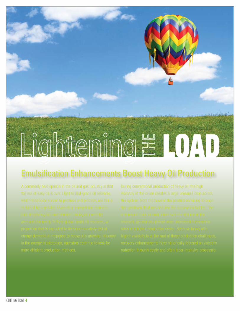
Emulsification Enhancements Boost Heavy Oil ProductionA commonly held opinion in the oil and gas industry is that
the era of easy oil is over. Light to mid-grade oil reserves,
which tend to be easier to produce and process, are being
replaced by a growing share of unconventional sources
including heavy oil and bitumen. Heavy oil currently
accounts for nearly 70% of global crude oil reserves , a
proportion that is expected to increase to satisfy global
energy demand. In response to heavy oil’s growing influence
in the energy marketplace, operators continue to look for
more efficient production methods.
During conventional production of heavy oil, the high
viscosity of the crude creates a large pressure drop across
the system, from the base of the production tubing through
the upstream flowlines and into the separation facility. The
end result? Loss of production over the lifetime of the
reservoir, greater equipment wear, increased intervention
rates and higher production costs. Because heavy oil’s
higher viscosity is at the root of these production challenges,
recovery enhancements have historically focused on viscosity
reduction through costly and often labor-intensive processes.
Lightening THE LOAD
CUTTING EDGE 5
For example, in situations where the oil is too viscous to flow in the reservoir, thermal recovery techniques such as steam-assisted gravity drainage (SAGD) and cyclic steam stimulation (CSS) have been used to heat and decrease the viscosity of the heavy oil to promote flow into the producing well. While both SAGD and CSS are incredibly efficient in terms of percent oil recovery, both require significant up-front capital investment and have come under intense scrutiny for the impact that their significant energy consumption and waste stream generation have on the environment.
Diluent injection represents a slightly more conventional approach to improving heavy oil production. Utilizing between five to twenty-five percent diluent based on the volume of produced oil, this method requires a relatively small capital investment for field-wide implementation. Although the diluent is partially recovered and recycled at downstream processing facilities, costs for continuous operation can be significant, as are the HS&E concerns around transportation, storage and handling of a highly flammable solvent.
Current production limitations have created opportunities for new innovation, particularly for technologies that require limited up-front capital expenditure and minimal modification to existing production facilities. The Biphasic Viscosity Reducer technology, or B-VR, is one such innovation that fills the technology gap by inducing the formation of a readily transported heavy oil-in-water emulsion using conventional production. The chemically induced emulsion does not require additional heat or diluent, is highly flow-able and stable under production conditions. Unlike conventional emulsion treatment programs, it will rapidly break to yield dry oil.
A Two Phase Solution
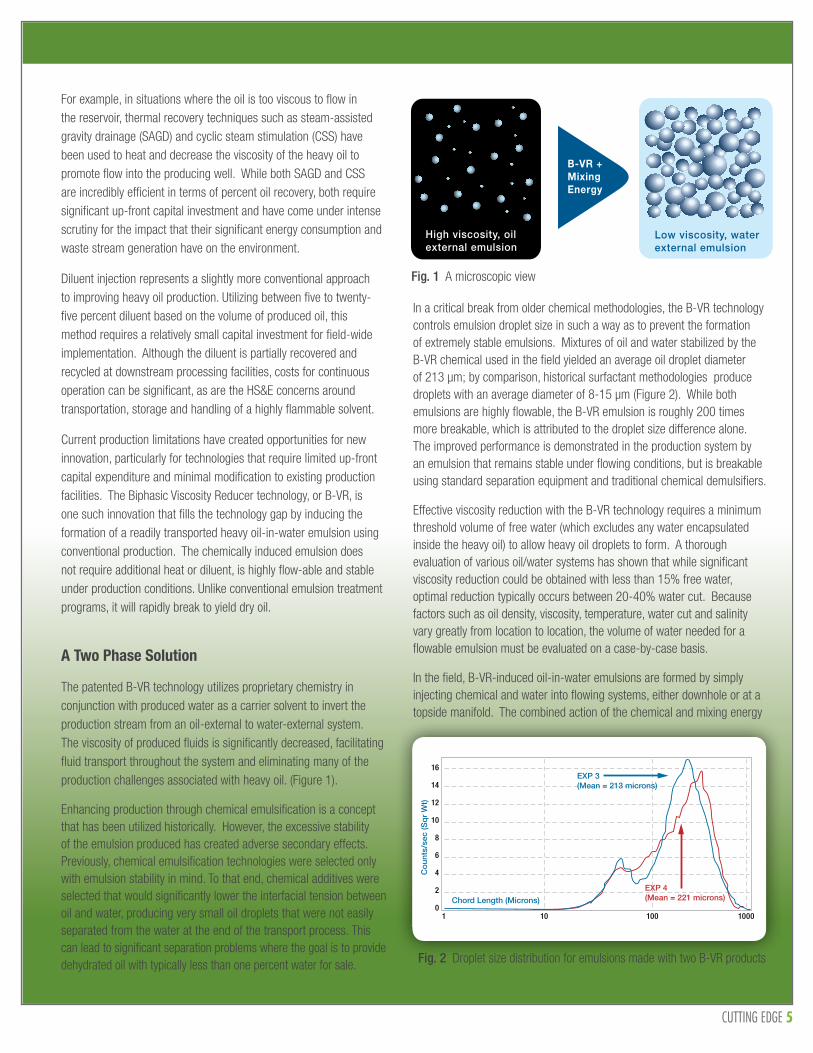
The patented B-VR technology utilizes proprietary chemistry in conjunction with produced water as a carrier solvent to invert the production stream from an oil-external to water-external system. The viscosity of produced fluids is significantly decreased, facilitating fluid transport throughout the system and eliminating many of the production challenges associated with heavy oil. (Figure 1).
Enhancing production through chemical emulsification is a concept that has been utilized historically. However, the excessive stability of the emulsion produced has created adverse secondary effects. Previously, chemical emulsification technologies were selected only with emulsion stability in mind. To that end, chemical additives were selected that would significantly lower the interfacial tension between oil and water, producing very small oil droplets that were not easily separated from the water at the end of the transport process. This can lead to significant separation problems where the goal is to provide dehydrated oil with typically less than one percent water for sale.
In a critical break from older chemical methodologies, the B-VR technology controls emulsion droplet size in such a way as to prevent the formation of extremely stable emulsions. Mixtures of oil and water stabilized by the B-VR chemical used in the field yielded an average oil droplet diameter of 213 µm; by comparison, historical surfactant methodologies produce droplets with an average diameter of 8-15 µm (Figure 2). While both emulsions are highly flowable, the B-VR emulsion is roughly 200 times more breakable, which is attributed to the droplet size difference alone. The improved performance is demonstrated in the production system by an emulsion that remains stable under flowing conditions, but is breakable using standard separation equipment and traditional chemical demulsifiers.
Effective viscosity reduction with the B-VR technology requires a minimum threshold volume of free water (which excludes any water encapsulated inside the heavy oil) to allow heavy oil droplets to form. A thorough evaluation of various oil/water systems has shown that while significant viscosity reduction could be obtained with less than 15% free water, optimal reduction typically occurs between 20-40% water cut. Because factors such as oil density, viscosity, temperature, water cut and salinity vary greatly from location to location, the volume of water needed for a flowable emulsion must be evaluated on a case-by-case basis.
In the field, B-VR-induced oil-in-water emulsions are formed by simply injecting chemical and water into flowing systems, either downhole or at a topside manifold. The combined action of the chemical and mixing energy
Fig. 1 A microscopic view
Fig. 2 Droplet size distribution for emulsions made with two B-VR products
High viscosity, oil external emulsion
Low viscosity, water external emulsion
B-VR +Mixing Energy
16
14
12
10
8
6
4
2
01 10 100 1000
Co
unts
/sec
(Sq
r W
t)
Chord Length (Microns)
EXP 3(Mean = 213 microns)
EXP 4(Mean = 221 microns)

CUTTING EDGE 6
(typically provided by the downhole pump) shears the oil into droplets that are suspended in the injected water, which acts as a carrier solvent for the droplets and isolates the oil from the pipe wall to reduce the drag effects of viscous fluids.
An Efficiency Boost
The B-VR technology platform’s operational value was evident in recent field trials in South America, where an 8° API gravity crude required naphtha to be injected as a diluent at a dosage of 35% by volume to facilitate production. A treatment consisting of 600 ppm of B-VR chemical and 25% by total volume of produced water was injected down the backside of the well and mixed with the heavy crude by an electric submersible pump (ESP) to form the water external emulsion.
As a result of this treatment, naphtha injection at the wellhead was cut from an average of 503 to 12 bpd—a reduction of nearly 98 percent—while production rates and system pressures remained relatively unchanged. Field operators determined that naphtha injection at the wellhead could be eliminated completely, but separation efficiency in the plant suffered slightly (Figure 3). Previous attempts to eliminate diluent during production resulted in a substantial increase in system pressure, ultimately shutting in the well (Figure 4).
Fig. 3. Tracking naphtha injection and wellhead pressure during B-VR injection
Fig. 4. Average pressures at the SW-4 wellhead based on production method
Total cost savings for the field trial, factoring in the total costs of chemical and water injection, resulted in a net savings of $6,446 (US) per day, per well based on reduced naphtha injection and handling costs. At this location, treatment with B-VR was estimated to generate a total savings of $2.3MM per year, in addition to minimizing operational risks to personnel and the environment .
Ultimately, the B-VR technology was successfully deployed with minimal capital investment and minor modification to system operations, and allowed the operator to optimize their heavy oil production potential in an environmentally sustainable way.
‘Field Study of Heavy Oil Viscosity Reduction for Production Transport.’ John Pinto, Giovanni Annichiaricco, Marcus Faust Jr., Magda Montanez, Ramon Parra, Thomas Weathers Jr., 2011 World Heavy Oil Congress.
‘Biphasic Viscosity Reducers as Production Aids for Viscous Oils.’ Marcus Faust Jr., Thomas Weathers Jr., 2011 SPE International Symposium on Oilfield Chemicals.
600
500
400
300
200
100
0
160
140
120
100
80
60
40
20
0
0 2 4 6 8
Day
10 12 14 16
PSI
Nap
thta
Inje
ctio
n (b
bl/
day
)
Wellhead Injection Rate
Wellhead Pressure
1000
900
800
700
600
500
400
300
200
100
0
B-VR Treatment ProgramNormal ProductionWith Diluent
Unassisted Production
Pressure (PSI)
Diluent Injection Volume (bbl/day)

CUTTING EDGE 7
High-Tech Monitoring Solutions for Better Scale Management
SCALING NEW HEIGHTS:
The presence of water in an oil field brings with it the potential
for mineral scale formation. Scale deposition from many mineral
sources, including calcium carbonate and sulfates of barium, calcium
and strontium, creates flow assurance challenges for operators
from the near wellbore to production tubing and topside processing
equipment. An ideal scale management program maximizes
hydrocarbon production and minimizes the cost of scale control,
thereby maintaining the economic viability of the operation.
SCALING NEW HEIGHTS:

CUTTING EDGE 8
Mitigation and prevention programs are critical for sustained production in oil and gas fields. Chemical methods of scale control include scale squeeze treatments, in which a scale inhibitor is pumped into the water-producing zone of a formation and returns with the produced fluid at sufficiently high concentrations to prevent scale precipitation. Continuous chemical injection is also an option. Monitoring for the presence of scale inhibitor chemical and the scaling ions in the produced fluid is a key part of a successful scale management program. Monitoring for suspended solids in terms of their concentration, mineral type, composition, and morphology is also recommended to improve the understanding and gauge the risk of scale formation.
Fig. 1 The cross section of a pipe that experienced scale build-up and flow assurance challenges
Fig. 2 Suspended solids analysis by SEM/EDS
Brine chemistry monitoringFrequent monitoring for changes in water chemistry is recommended for all water-producing wells, and becomes even more critical in the case of a seawater flood, a secondary recovery technique in which seawater is injected into the formation via an injection well to displace residual oil and sweep it to adjacent production wells. Because the compositions of the formation and injected waters can differ significantly, the use of preliminary modeling to predict scaling tendency and risks associated with well production fluids is common.
A laboratory-derived Minimum Inhibitor Concentration (MIC) is used to define whether a particular system is protected against predicted scale formation risks. If the scale inhibitor chemical is present at a concentration above the MIC, then it is assumed that the well is protected. It is often observed that the actual “field” MIC differs significantly from the laboratory-derived MIC; however, this approach works reasonably well if combined with monitoring of the scaling-ion concentrations (those present as well as those apparently missing in action).
Suspended-solids monitoringMonitoring for suspended solids is also often recommended, especially in relatively long-reach horizontal wells. It is useful to understand not only the amount of suspended solids recoverable from a given volume of produced water, but their composition and morphology as well. Figure 2 outlines a process to recover and characterize suspended solids contained in produced water.
A Scanning Electron Microscope equipped with Energy Dispersive X-Ray Spectroscopy (SEM/EDS) can be used to identify the chemical composition of the solids, in addition to their crystal morphology. This enables the operator to distinguish between scale particulates and drilling or completion additives containing barite or calcite. SEM/EDS systems equipped with a low-vacuum mode are recommended to reduce specimen changing and eliminate the need to apply a conductive coating to the specimen. In low-vacuum mode, the instrument introduces a small amount of air into the specimen chamber. These air molecules, oxygen and nitrogen, are ionized by the incident electrons. These ions neutralize electrons on the surface of the specimen and eliminate charging so that a non-conductive specimen can be observed.
Suspended Solids and Environmental Scanning Electron Microscopy (ESEM) Analysis Program
As part of the scale management program, suspended solids from the produced water can be analyzed for composition, amount and size to determine the effectiveness of the downhole and topside scale control program.
Produced fluid sample
SEM of suspended solids on filter surface
SEM of suspended solids on filter surface
Barium Sulphate Scale Crystals formed with no Scale Inhibitor
Barium Sulphate Drilling Mud
Barium Sulphate Scale formed in the presence of Scale Inhibitor (SI<MIC)
Calcium Carbonate Scale Crystals No Scale Inhibitor present
Whatman 0.45m SFCA Filter
50ml
H2O
H2O
OIL
Wax Crystals recovered from Produced Water
Fragment of Corrosion Resistant Alloy (CRA)
Essential Expertise for Water, Energy and AirSM

CUTTING EDGE 9
Suspended-solids monitoring is an effective tool to assess the frequency at which a scale squeeze must be repeated in production wells. It can also help the operator determine the root cause of overboard oil-in-water excursions. Of critical importance for long-reach wells, this monitoring identifies those areas in the formation where an inhibitor squeeze has not achieved optimal placement, (i.e., where high inhibitor residuals, well above MIC, are accompanied by high concentrations of suspended solids).
Suspended-solids monitoring also offers opportunities to simplify scale surveillance in complex subsea architectures, where the need for frequent sampling of individual wells can cause significant hydrocarbon deferment. It achieves this by the fact that, so long as suspended-particulates counts in a commingled flow stream are sufficiently low, all wells in this stream should—in principle—be under effective control. Only when counts begin to rise is frequent individual sampling of wells recommended. Of course, the risks associated with this reduced level of surveillance for much of the scaling lifecycle must be balanced against the benefits of reduced sampling.
SEM/EDS analysis can identify scale issues when traditional methods of monitoring (scaling ion concentration and scale inhibitor residuals) show no immediate concerns. For example, Figure 3 shows calcium carbonate grains observed in a well that also exhibited steady scaling ion concentrations. Based on these findings, a scale squeeze treatment was recommended and executed. SEM/EDS analysis after the squeeze confirmed that the treatment was necessary and successful (Figure 4).
Nalco widely employs a suspended-solids surveillance method in offshore and onshore operations around the world to support scale programs and optimize both continuous and batch inhibitor applications. The recent purchase of a new SEM/ EDS unit by the Diagnostic Solutions Group in Sugar Land, TX further strengthens Nalco’s capabilities to provide a more ‘real-time’ assessment of a scale control program’s efficacy. Ultimately, this will give the operator greater confidence in their flow assurance management strategies and their ability to optimize production.
Fig. 3 SEM micrographs coupled with elemental analysis using EDS confirmed calcium carbonate in a well, despite steady scaling ion concentrations
Fig. 4 SEM micrographs comparing suspended solids on a filter at 50X before the squeeze (left) and at 25X after the squeeze treatment (right)
Before Squeeze After Squeeze
Fig. 5 SEM/EDS systems are used to support scale management programs at Nalco Sugar Land, TX; Naperville, IL; Macae, Brazil; Leiden, The Netherlands; and Aberdeen, UK facilities.
Publications
1. Jordan, M.M, Mackin, K., Johnston, C.J and Feasey, N.D. “Control of Hydrogen Sulphide Scavenger Induced Scale and the Associated Challenge of Sulphide Scale Formation within North Sea High Temperature/High Salinity Fields Production Wells. Laboratory Evaluation to Field Application” SPE 87433. Presented at SPE International Symposium on Oilfield Scale, Aberdeen, 26-27 May 2004.
2. Jordan, M.M, Johnston, C.J. and Robb, M. “Evaluation Methods for Suspended solids and Produced Water as an aid in Determining Effectiveness of Scale Control both down-hole and Topside” SPE 92663. Presented at SPE International Symposium on Oilfield Chemistry 2-4th February 2005, Houston, Texas.

CUTTING EDGE 10
What do
have in common?
&SuperheroesSuperheroes
PolymerPolymer
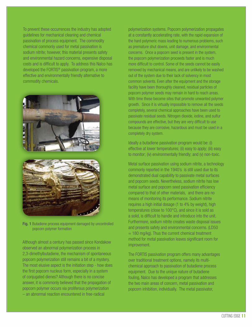
It’s not only Superman that can bend steel, polymer can too! What real harm can polymerization do? It can cause some unwanted by-products, increase viscosity, restrict flow, but the real burden is usually the clean-up and removal during a turn-around. This is not the case within the butadiene industry, where polymerization, if not properly controlled, can cause extensive system damage (Figure 1).
CUTTING EDGE 11
To prevent these occurrences the industry has adopted guidelines for mechanical cleaning and chemical passivation of process equipment. The commodity chemical commonly used for metal passivation is sodium nitrite; however, this material presents safety and environmental hazard concerns, expensive disposal costs and is difficult to apply. To address this Nalco has developed the FORTIS® passivation program, a more effective and environmentally friendly alternative to commodity chemicals.
Fig. 1 Butadiene process equipment damaged by uncontrolled popcorn polymer formation
Although almost a century has passed since Kondakow observed an abnormal polymerization process in 2,3-dimethylbutadiene, the mechanism of spontaneous popcorn polymerization still remains a bit of a mystery. The most elusive aspect is the initiation step - how does the first popcorn nucleus form, especially in a system of conjugated dienes? Although there is no concise answer, it is commonly believed that the propagation of popcorn polymer occurs via proliferous polymerization – an abnormal reaction encountered in free-radical
polymerization systems. Popcorn polymerization propagates at a constantly accelerating rate, with the rapid expansion of the hard polymeric mass leading to numerous problems, such as premature shut downs, unit damage, and environmental concerns. Once a popcorn seed is present in the system, the popcorn polymerization proceeds faster and is much more difficult to control. Some of the seeds cannot be easily removed by mechanical means, and are unlikely to be washed out of the system due to their lack of solvency in most common solvents. Even after the equipment and the storage facility have been thoroughly cleaned, residual particles of popcorn polymer seeds may remain in hard to reach areas. With time these become sites that promote unwanted polymer growth. Since it is virtually impossible to remove all the seeds completely, several chemical approaches have been used to passivate residual seeds. Nitrogen dioxide, iodine, and sulfur compounds are effective, but they are very difficult to use because they are corrosive, hazardous and must be used in a completely dry system.
Ideally a butadiene passivation program would be: (i) effective at lower temperatures; (ii) easy to apply; (iii) easy to monitor; (iv) environmentally friendly; and (v) non-toxic.
Metal surface passivation using sodium nitrite, a technology commonly reported in the 1940’s is still used due to its demonstrated dual capability to passivate metal surfaces and popcorn seeds. Nevertheless, sodium nitrite has low metal surface and popcorn seed passivation efficiency compared to that of other materials, and there are no means of monitoring its performance. Sodium nitrite requires a high initial dosage (1 to 4% by weight), high temperatures (close to 100°C), and since it is sold as a solid, is difficult to handle and introduce into the unit. Furthermore, sodium nitrite creates waste disposal issues and presents safety and environmental concerns. (LD50 = 180 mg/kg). Thus the current chemical treatment method for metal passivation leaves significant room for improvement.
The FORTIS passivation program offers many advantages over traditional treatment options, namely its multi-chemical approach to passivation of butadiene process equipment. Due to the unique nature of butadiene fouling, Nalco has developed a program that addresses the two main areas of concern, metal passivation and popcorn inhibition, individually. The metal passivator,

CUTTING EDGE 12
EC3243A, is effective at lower temperatures (ca. 80°C) and lower concentrations than the commodity chemical. In a similar fashion the popcorn passivator, EC3362B, effectively terminates radical sites, and has successfully passivated popcorn seeds in both laboratory studies and field tests.
EC3243A passivates a metal surface by changing the oxidation state of iron from hematite to magnetite. The effective conversion of a metal surface from hematite (brown-red) to magnetite (gray-black) results in a protective layer that will mitigate corrosion and reduce the rate of initiation of free-radical polymeric fouling. In the laboratory, the passivation efficiency of EC3243A relative to sodium nitrite was evaluated by treating previously corroded carbon steel coupons with aqueous solutions of the passivation chemicals.
Figure 2 shows the corroded coupons before and after treatment with a 4% solution of sodium nitrite or a 1% solution of EC3243A for 48 hours at 80°C. The coupon treated with EC3243A developed a magnetite protective layer, as indicated by the grey/black coloration. The coupon treated with sodium nitrite showed little change.
Fig. 2 Coupons before (left) and after (right) treatment with EC3234A and sodium nitrite solutions
Fig. 3 Passivated popcorn seeds grown in 2,3-dimethylbutadiene vapors for 3 weeks
The other component of the FORTIS program is the popcorn passivator, EC3362B. In the laboratory, experiments to evaluate the relative inhibitor performance were conducted to test the passivation effects over an extended period of time. Popcorn seeds previously immersed in aqueous solutions of the chemicals were allowed to grow in 2,3-dimethylbutadiene vapors for three weeks, and their growth was compared to that of an untreated seed. The impressive effect of EC3362B passivation is shown in Figure 3. While sodium nitrite was able to reduce the seed growth by a factor of 3 relative to the untreated seed, EC3362B was able to reduce the growth of the seed by a factor of 15, when compared to the untreated seed growth.
So although popcorn polymer may be able to bend steel, unlike Superman, there is a way to stop it. The Nalco FORTIS passivation program is effective at popcorn passivation, uses lower metal passivation temperatures, lower dosages, is easily applied and monitored, and is environmentally friendly.
4 wt% NaNO2 1 wt% EC3243A
CUTTING EDGE 13
As our thirst for hydrocarbon-based
products grows, new technology
plays a critical role in enabling the
continued production of hydrocarbons
and the manufacture of fuels and
petrochemical feedstocks. Having
a critical mass of R&D intellectual
capital coupled with a deep rooted
culture of innovation is vital in order
to succeed in this environment.
Over the past two years Nalco has
significantly expanded its innovation
footprint around the globe to
include new innovation centers in
Pune, India; Shanghai, China and
Campinas, Brazil. Furthermore, with
the acquisition of the enhanced oil
recovery company TIORCO, a new
state of the art research center was
commissioned in Denver, Colorado.
Recently in Sugar Land, Texas, the
Energy R&D center was further
expanded with the opening of a new
15,000 sq. foot laboratory to house
the Downstream R&D group.
FootprintGrowing
the innovation

CUTTING EDGE 14
The new Innovation Center in Pune, India, is Energy Services’ Eastern hemisphere R&D hub. The facility has over 50 scientists and engineers, 70% of whom have PhDs from premier institutes in India and around the world. Great attention has been paid to standardizing the equipment, processes and level of training in order to ensure the output from this facility is of the same high standard as our established laboratories.
The facility in Shanghai, China has over 60 scientists and engineers and is strategically located to service water and process needs across industries including downstream refining and petrochemical businesses. Similarly, the facility in Campinas, Brazil has approximately 15 scientists and engineers and supports our upstream business in addition to the paper and biofuels industries.
These innovation centers are chartered with developing new, differentiated technologies that will enable the future state of the petroleum industry. Research projects, which typically last from six months to three years, are directly aligned with industry needs. Projects are locally coordinated but typically involve an extended global team of scientists that collaborate to drive the work forward. Open, regular communication is critical to success. In addition to leading the development of new technologies,
the Nalco R&D team also works closely with customers, Nalco field engineers, and technologists at regional technical support centers to provide solutions to today’s high-value technical challenges. This may involve field support or being able to simulate process conditions in a laboratory environment. By having the research team exposed to real-world technical support projects in addition to research ensures that they gain a first-hand appreciation of operational challenges and that their research work remains focused on viable solutions that can be implemented rather than scientific curiosities.
“Do not go where the path may lead, go instead where there is no path and leave a trail.” – R. Emerson
In order to drive the creative process of developing the next breakthrough technology, the R&D team is continually challenged to think beyond the obvious and look outside their immediate fields for sources of innovation stimulus. Examples of this include recent collaborations with NASA and the Methodist Hospital in Houston to mine technologies in these fields that may have functionality that can be leveraged into the petroleum industry. Connecting with new sources of innovation stimulus, and collaborating both internally or externally to quickly bring to the marketplace differentiated, innovative solutions is the backbone to the Connect – Collaborate – Innovate strategy that was recently implemented throughout Energy Services R&D.
Looking ‘beyond the trees’ for sources of innovation stimulus and then ‘connecting the dots’ between technologies is the fundamental process of innovation. With the recently announced merger of Nalco and Ecolab, the world’s leading provider of cleaning and sanitization solutions, many opportunities now exist for doing exactly this within the new expanded company. Furthermore, the newly merged company has more than double the original number of scientists and engineers (total of 1400), in 10 innovation centers around the globe. With an active patent portfolio of over 5,800 patents there exists a wealth of knowledge that is a fertile resource for continued innovation.
The future of the petroleum industry is bright. However, it will take sustained, focused innovation to meet the continued challenges our industry poses us. Nalco has clearly made a commitment to innovation leadership and continues to invest heavily to ensure tomorrow’s challenges are being addressed today.
“Discovery consists of seeing what everybody has seen and thinking what nobody has thought.”– Albert von Szent-Gyorgy
Innovation CentersRegional Technical Support Centers

CUTTING EDGE 15
COVER STORY
WindowCorrosion
In refinery processing, the “corrosion window” refers to the relatively brief period of time in which an upset
to normal operation causes rapid corrosion in the overhead condensing system of a crude atmospheric
distillation unit. The corrosion window typically follows the empirical observation that 90% of crude-
unit overhead corrosion occurs during only 10% of operating time. This window normally opens during
interruptions to normal operation, such as crude tank switches and processing of slop oils or opportunity
crudes. Because periods of unstable operation are infrequent and/or short-lived, traditional approaches to
corrosion monitoring tend to detect corrosion problems only after significant damage has already occurred.
AReal-Time
Viewinto the

CUTTING EDGE 16
A Break from Traditional Treatments
Traditional methods for controlling corrosion in the overhead condensing system include the installation of corrosion monitoring devices, the use of caustic, and other chemical solutions. Some refiners also elect to upgrade the metallurgy of the overhead condensing system and all associated piping, a relatively high-cost option.
When properly applied, traditional approaches provide acceptable corrosion control during periods of normal operation; however, these methods are neither sensitive enough nor employed with sufficient frequency, reliability and accuracy to facilitate a timely response within the corrosion window.
The refining industry is actively seeking new solutions that can instantaneously and accurately detect significant changes in the corrosive environment. Furthermore, the applied solution must proactively correct any corrosion issues in an effective and timely manner. The Nalco response to this challenge is the 3D TRASAR Crude Overhead Analyzer (Fig. 1), an automated, on-line analyzer that continuously measures pH, chlorides, and iron contents in refinery process water.
Monitoring Outside the Corrosion Window
Both refiners and chemical suppliers use a combination of wet chemistry tests and mechanical devices to monitor the corrosive environment in crude overhead condensing equipment. Wet chemistry tests, which often include measurements of pH, chloride, ammonia, sulfide, and iron contents in the overhead accumulator water, are limited in their effectiveness at monitoring and controlling corrosion by the frequency at which these test are performed. Sampling and testing of the overhead accumulator water is generally performed by refinery personnel or the chemical supplier as part of a routine service plan. The frequency of this sampling may vary from once per shift to once per week, and the test protocols may be limited to simple pH and chloride measurements.
The result is minimal data collection, with most of the sampling occurring during periods of stable operations. Although 90% of corrosion occurs during upsets in the crude unit, sampling and data collection during these periods are often neglected while refinery staff works to return the crude unit to stable operations.
The most frequently measured parameter in the crude unit overhead accumulator water stream is pH, which may be checked 4 to 10 times a day. While some refiners have installed online pH probes to monitor the process water, manual pH measurements remain the norm, primarily due to the low reliability of online probes and their need for frequent calibration. Chloride, iron, and ammonia contents in the process water are measured much less frequently—normally 1 to 5 times per week—due to the complexity and time required to complete these tests.
Manual wet chemistry results must be reported accurately and rapidly if corrosion issues are to be addressed proactively. Test accuracy is significantly affected by human error, variation in test methods, and the temptation to take shortcuts during analysis. Just as important, the length of time between sampling, testing, and reporting results impacts the value of the data. For example, a typical 4 to 6 hour turnaround
time may be adequate during normal operation or for comparison to performance metrics, but does not allow a timely response within the corrosion window.
Peering Inside the Corrosion Window
The ability to respond proactively to corrosion issues requires accurate, frequent, and timely testing. This suggests the need for effective, real-time monitoring solutions, which is precisely what the Nalco 3D TRASAR Crude Unit Overhead Analyzer provides.
Process water from the crude unit overhead is continuously sampled and fed through the 3D TRASAR Analyzer for automated, on-line analyses. Specially designed pH electrodes provide a real-time measure of the accumulator water pH. Chloride and total iron analyses are typically measured once per hour, depending on system conditions. The analyzer processes samples continuously, both during normal operation
Fig. 1 Photo of 3D TRASAR Crude Overhead Analyzer
CUTTING EDGE 17
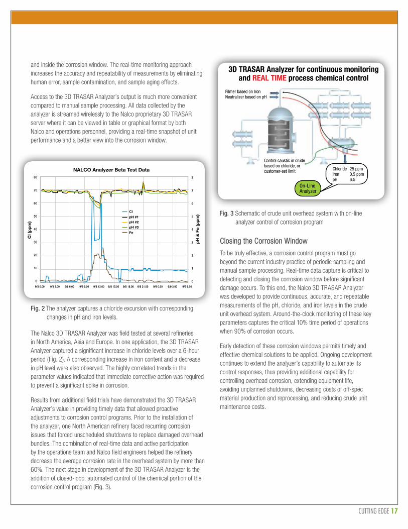
Fig. 2 The analyzer captures a chloride excursion with corresponding changes in pH and iron levels.
Fig. 3 Schematic of crude unit overhead system with on-line analyzer control of corrosion program
and inside the corrosion window. The real-time monitoring approach increases the accuracy and repeatability of measurements by eliminating human error, sample contamination, and sample aging effects.
Access to the 3D TRASAR Analyzer’s output is much more convenient compared to manual sample processing. All data collected by the analyzer is streamed wirelessly to the Nalco proprietary 3D TRASAR server where it can be viewed in table or graphical format by both Nalco and operations personnel, providing a real-time snapshot of unit performance and a better view into the corrosion window.
80
70
60
50
40
30
20
10
0
8
7
6
5
4
3
2
1
0
9/8 0.00 9/8 3.00 9/8 6.00 9/8 9.00 9/8 12.00 9/8 15.00 9/8 18.00 9/8 21.00 9/9 0.00 9/9 3.00 9/9 6.00
NALCO Analyzer Beta Test Data
Cl (
pp
m)
pH
& F
e (p
pm
)
Cl
Fe
pH #1pH #2
pH #3
The Nalco 3D TRASAR Analyzer was field tested at several refineries in North America, Asia and Europe. In one application, the 3D TRASAR Analyzer captured a significant increase in chloride levels over a 6-hour period (Fig. 2). A corresponding increase in iron content and a decrease in pH level were also observed. The highly correlated trends in the parameter values indicated that immediate corrective action was required to prevent a significant spike in corrosion.
Results from additional field trials have demonstrated the 3D TRASAR Analyzer’s value in providing timely data that allowed proactive adjustments to corrosion control programs. Prior to the installation of the analyzer, one North American refinery faced recurring corrosion issues that forced unscheduled shutdowns to replace damaged overhead bundles. The combination of real-time data and active participation by the operations team and Nalco field engineers helped the refinery decrease the average corrosion rate in the overhead system by more than 60%. The next stage in development of the 3D TRASAR Analyzer is the addition of closed-loop, automated control of the chemical portion of the corrosion control program (Fig. 3).
Closing the Corrosion Window
To be truly effective, a corrosion control program must go beyond the current industry practice of periodic sampling and manual sample processing. Real-time data capture is critical to detecting and closing the corrosion window before significant damage occurs. To this end, the Nalco 3D TRASAR Analyzer was developed to provide continuous, accurate, and repeatable measurements of the pH, chloride, and iron levels in the crude unit overhead system. Around-the-clock monitoring of these key parameters captures the critical 10% time period of operations when 90% of corrosion occurs.
Early detection of these corrosion windows permits timely and effective chemical solutions to be applied. Ongoing development continues to extend the analyzer’s capability to automate its control responses, thus providing additional capability for controlling overhead corrosion, extending equipment life, avoiding unplanned shutdowns, decreasing costs of off-spec material production and reprocessing, and reducing crude unit maintenance costs.
CUTTING EDGE 18
Publications & Industry Presentations
UPSTREAM ‘Optimization of a Microbial Control Program in an Aging Gulf of Mexico Asset to Minimize the Risk of Corrosion.’ Renato De Paula, Vic Keasler, Brian Bennett, Carrie Keller, and Robert C. Adams. NACE 2012.
‘Multi-Faceted Approach for Optimizing a Microbial Control Program.’ Vic Keasler, Brian Bennett, Carrie Keller. SPE International Conference on Oilfield Corrosion 2012. Paper # SPE-154645.
‘Development and Application of MEG Reclamation Process Compatible Corrosion Inhibitors for Upstream Oil and Gas Developments.’ Ryan Harrington, Mark Gough, Steve Davoren, 18th International Corrosion Congress 2011.
‘Separation of Produced Emulsions from Surfactant Enhanced Oil Recovery Processes.’ George J. Hirasaki, Clarence A. Millera, Olina G. Raneya, Michael K. Poindexter, Duy T. Nguyen, John Hera, Energy and Fuels, 2011.
‘Use of Foamer to Deliquify Natural Gas Wells with Dry-Gas-Lift System.’ Fenfen Huang, Duy Nguyen, Adam Rowe, Gas Well Deliquification Workshop, 2011.
‘Deliquification Strategy for North Everest.’ Sabina Rattan , Karl Stevens, Duy Nguyen, Gas Well Deliquification Workshop, 2011.
‘Selection of the Right Demulsifier for Chemical Enhanced Oil Recovery.’ Duy Nguyen, Nicholas Sadeghi, SPE-International Oil Chemicals, 2011.
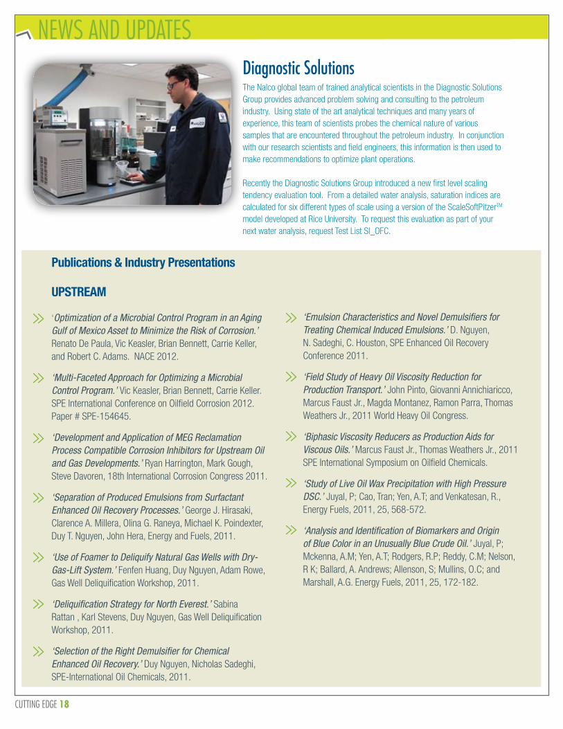
NEWS AND UPDATESDiagnostic SolutionsThe Nalco global team of trained analytical scientists in the Diagnostic Solutions Group provides advanced problem solving and consulting to the petroleum industry. Using state of the art analytical techniques and many years of experience, this team of scientists probes the chemical nature of various samples that are encountered throughout the petroleum industry. In conjunction with our research scientists and field engineers, this information is then used to make recommendations to optimize plant operations.
Recently the Diagnostic Solutions Group introduced a new first level scaling tendency evaluation tool. From a detailed water analysis, saturation indices are calculated for six different types of scale using a version of the ScaleSoftPitzerTM model developed at Rice University. To request this evaluation as part of your next water analysis, request Test List SI_OFC.
‘Emulsion Characteristics and Novel Demulsifiers for Treating Chemical Induced Emulsions.’ D. Nguyen, N. Sadeghi, C. Houston, SPE Enhanced Oil Recovery Conference 2011.
‘Field Study of Heavy Oil Viscosity Reduction for Production Transport.’ John Pinto, Giovanni Annichiaricco, Marcus Faust Jr., Magda Montanez, Ramon Parra, Thomas Weathers Jr., 2011 World Heavy Oil Congress.
‘Biphasic Viscosity Reducers as Production Aids for Viscous Oils.’ Marcus Faust Jr., Thomas Weathers Jr., 2011 SPE International Symposium on Oilfield Chemicals.
‘Study of Live Oil Wax Precipitation with High Pressure DSC.’ Juyal, P; Cao, Tran; Yen, A.T; and Venkatesan, R., Energy Fuels, 2011, 25, 568-572.
‘Analysis and Identification of Biomarkers and Origin of Blue Color in an Unusually Blue Crude Oil.’ Juyal, P; Mckenna, A.M; Yen, A.T; Rodgers, R.P; Reddy, C.M; Nelson, R K; Ballard, A. Andrews; Allenson, S; Mullins, O.C; and Marshall, A.G. Energy Fuels, 2011, 25, 172-182.

CUTTING EDGE 19
UPSTREAM ‘Effect of Aging on Asphaltene Inhibitor Product Recommendation.’ Juyal, P.; Le, V; Yen, Andrew, T; Allenson, S.J. Journal of Dispersion Science and Technology, (2011) 32:8, 1096-1104.
‘Application of Emulsion Viscosity Reducers to Lower Produced Fluid Viscosity.’ Stephan J Allenson, Andrew T Yen and Frank Lang. OTC 22443. Proceedings of Offshore Technology Conference, 4th – 6th October 2011, Rio de Janeiro, Brazil.
‘Analysis and Comparison of Paraffinic Field Deposits to Cold Finger Deposits on a Brazilian Campos Basin Crude Oil.’ Susan Garner, Priyanka Juyal, Crystal Hart, , David Podgorski, Amy M McKenna, Claudio Ziglio, Ryan P Rodgers, Stephan Allenson, Alan G Marshall. Paper OTC 22660. Proceedings of Offshore Technology Conference, 4th – 6th October 2011, Rio de Janeiro, Brazil. (Joint publication with Petrobras and Florida State University)
‘Evaluation of Kinetic Hydrate Inhibitor Performance by High Pressure Differential Scanning Calorimetry.’ Kevin McNamee. Paper OTC 21604. Proceedings of Offshore Technology Conference, May 3, 2011, Houston, TX.
‘Characterization of Crude Oil and Asphaltenes from an Elevated GOR Production Well in the Gulf of Mexico.’ Nikhil Joshi, Priyanka Juyal, Frank Lim, Amy M McKenna, David Podgorski, Vickie Ho, Andrew T Yen, Ryan P Rodgers, Stephan J Allenson, Alan G Marshall. 12th Int’l Conf. on Petroleum Phase Behavior & Fouling, London, UK, July 10th-14th (2011).
‘Combined Rheometry and Differential Scanning Calorimetry Study of Wax Precipitation in Live Fluids under Pressure.’ Priyanka Juyal, Tran Cao and Andrew Yen. 12th Int’l Conf. on Petroleum Phase Behavior & Fouling, London, UK, July 10th-14th (2011).
‘Reversibility of Asphaltene Flocculation with Chemical Inhibitors.’ Priyanka Juyal, Vickie Ho, Andrew Yen and Stephan Allenson. 12th Int’l Conf. on Petroleum Phase Behavior & Fouling, London, UK, July 10th-14th (2011).
DOWNSTREAM ‘Beyond the Desalter;’ Brad Mason; Hydrocarbon Engineering, v 16, n 10, October 2011.
‘Rise of European Ethanol;’ Tony O’Brien, Phil Bureman and Kim Peyton; Biofuels International, October 2011.
‘Peroxy Radical Activated Addition of tert-Butylcatechol to 2,6-Di-tert-butyl-7-Substituted Quinone Methide Polymerization Retarders;’ Andrew R. Neilson and Christopher F. Morrison; Organic Process Research & Development, November 11, 2011.
‘Green Retarder Technology for the Styrene Industry.’ Ana Guzman, Carmen Monfort and Ana Olivares (Repsol Química Tarragona); Lisheng Xu, Javier Florencio, Vincent E. Lewis, and Christopher F. Morrison (Nalco), EB/SM Technology Conference, San Francisco, CA, June 5- 7, 2011.
‘Flux Oil Stream Import to Quench Systems - Risks and Impacts.’ Andre Bernard, Thomas Pickett, Dan Frye, and Beata Manek, AIChE Spring Meeting, Chicago, IL, March 13-17, 2011.
‘Nalco - Your Partner in Delivering Improved Ethylene Plant Reliability.’ Andrew Neilson, 15th Annual ROPTC, Bali, Indonesia, January 2011.
Ecolab is a trademark of Ecolab USA, Inc. FORTIS and 3D TRASAR, Nalco, the logo and the tagline are trademarks of Nalco Company. All other trademarks are the property of their respective owners. ©2012 Nalco Company. All Rights Reserved. 02/12 ADV-1403
Energy Services Division: 7705 Highway 90-A • Sugar Land, Texas 77478 • USAEurope: A-One Business Center • Z.A. La Piéce 1 • Route de l’Etraz • 1180-Rolle • Switzerland Gulf Office: P.O. Box 17063 • Jebel Ali Free Zone • Dubai, United Arab EmiratesLatin America: Av. das Nações Unidas 17.891 • 6° Andar 04795-100 • São Paulo • SP • BrazilAsia Pacific: 2 International Business Park • #02-20 The Strategy Tower 2 • Singapore 609930 India: Kumar Planet IT • Magarpatta City Road • Hadapsar • Pune • India 411028
We rely on the diversity of our workforce to drive our growth and success. Our competitive salaries and benefits, as well as unlimited opportunities for professional growth and development, make Nalco a great place to work. EOE
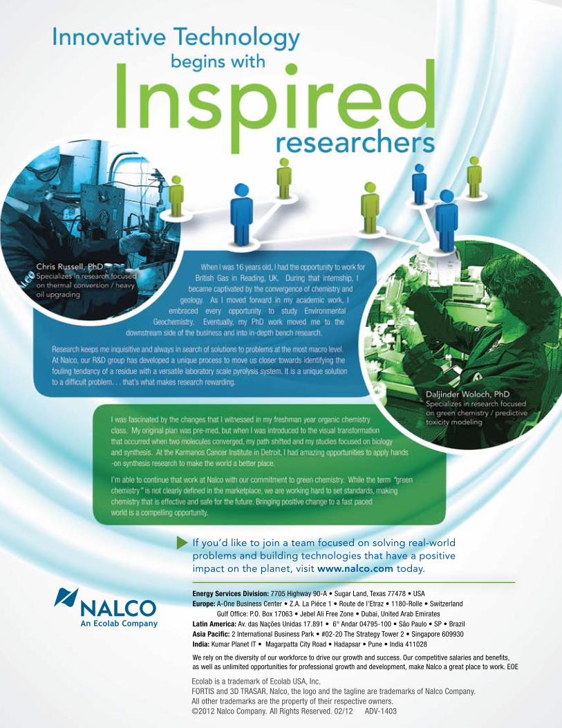
If you’d like to join a team focused on solving real-world problems and building technologies that have a positive impact on the planet, visit www.nalco.com today.Essential Expertise
for Water, Energy and AirSM
An Ecolab Company