Embed Size (px)
Citation preview
COMBUSTION IN POROUS MEDIA☼
BY Prof. Dr. Mohammed
Hamdan&
Eng. NABEEL ABO SHABAN
CONTENTSPART 1 : Theoretical background & Introduction Combustion = Chemical reactions Heating values of fuel fundamentals of combustion
PART 2 : Combustion in porous media Porous materials Porous burners Flame propagation Modeling of flame in porous media
Terminology
Fuel Flame Porous Media
Fuel
is a substance whose oxidation reaction is strongly exothermic.
FLAME Is the visible oxidation (combustion) of gaseous material There is no flame unless you have burning gases, therefore a liquid or solid material can only burn with a flame if it is converted into gaseous fuel.
POROUS MEDIA
Is presence of both a persistent solid matrix and avoid spacewhich is occupied by one or morefluid phases within porous media domain . Rocks,ceramics,Human tissue are examples of porous media.
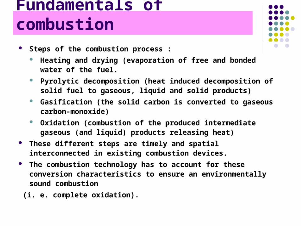
Fundamentals of combustion Steps of the combustion process :
Heating and drying (evaporation of free and bonded water of the fuel.
Pyrolytic decomposition (heat induced decomposition of solid fuel to gaseous, liquid and solid products)
Gasification (the solid carbon is converted to gaseous carbon-monoxide)
Oxidation (combustion of the produced intermediate gaseous (and liquid) products releasing heat)
These different steps are timely and spatial interconnected in existing combustion devices.
The combustion technology has to account for these conversion characteristics to ensure an environmentally sound combustion
(i. e. complete oxidation).
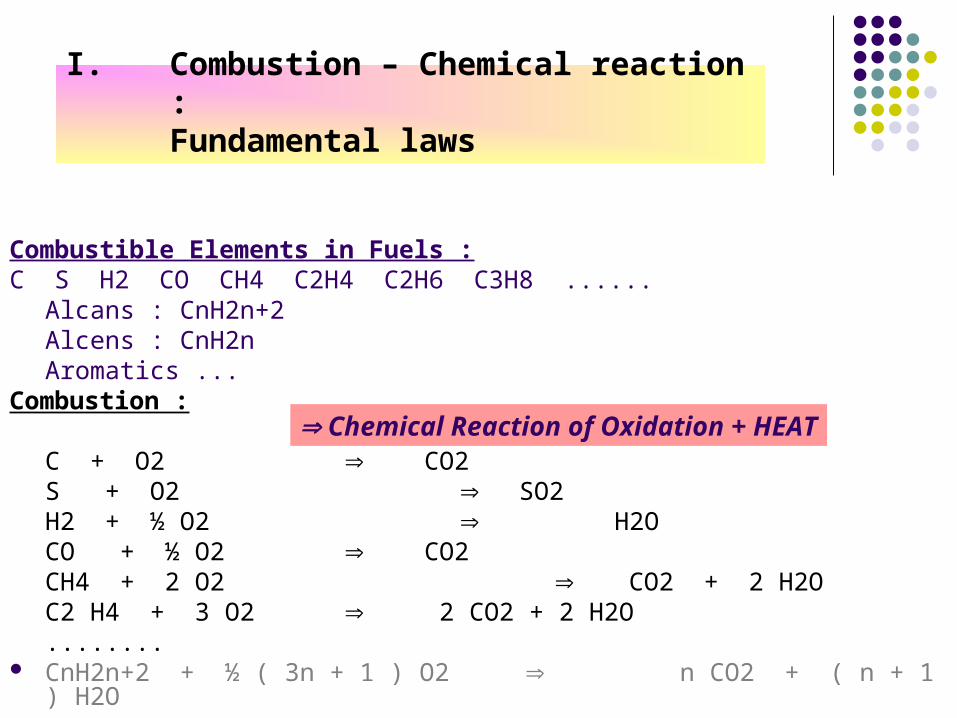
I. Combustion – Chemical reaction : Fundamental laws
Combustible Elements in Fuels :C S H2 CO CH4 C2H4 C2H6 C3H8 ......
Alcans : CnH2n+2Alcens : CnH2nAromatics ...
Combustion :
C + O2 CO2S + O2 SO2H2 + ½ O2 H2OCO + ½ O2 CO2CH4 + 2 O2 CO2 + 2 H2OC2 H4 + 3 O2 2 CO2 + 2 H2O........
CnH2n+2 + ½ ( 3n + 1 ) O2 n CO2 + ( n + 1 ) H2O
Chemical Reaction of Oxidation + HEAT

II. Heating values of fuelsCombustible Elements in Fuels :
C S H2 CO CH4 C2H4 C2H6 C3H8 ......Alcans : CnH2n+2
Alcens : CnH2n
Aromatics ... Combustion :
N° Chemical Reaction Ref. : Standard Conditions
Heat kJ/kmole
Heat kJ/kg
Heat kJ/m3
N 1 C + O2 CO2 404400 33700 - 2 C + ½ O2 CO 121400 10117 - 3 S + O2 SO2 296930 9279 - 4 CO + ½ O2 CO2 283000 10107 12626 5 C + 2 H2 CH4 85800 7140 6 H2 + ½ O2 H2O VAP 241800 120900 10790 7 H2 + ½ O2 H2O LIQ 285800 142900 12750 8 CH4 + 2 O2 CO2 + 2 H2OVAP 802200 50040 35790 9 CH4 + 2 O2 CO2 + 2 H2OLIQ 890200 55637 39710
/ / 22.414
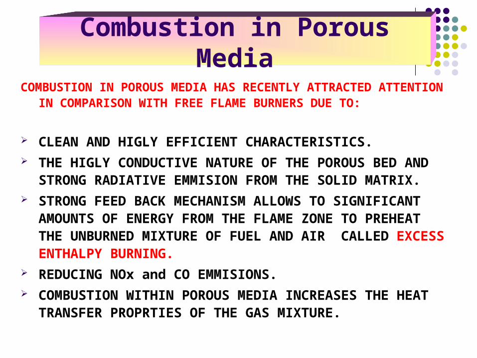
Combustion in Porous MediaCOMBUSTION IN POROUS MEDIA HAS RECENTLY ATTRACTED
ATTENTION IN COMPARISON WITH FREE FLAME BURNERS DUE TO:
CLEAN AND HIGLY EFFICIENT CHARACTERISTICS. THE HIGLY CONDUCTIVE NATURE OF THE POROUS BED AND
STRONG RADIATIVE EMMISION FROM THE SOLID MATRIX. STRONG FEED BACK MECHANISM ALLOWS TO SIGNIFICANT
AMOUNTS OF ENERGY FROM THE FLAME ZONE TO PREHEAT THE UNBURNED MIXTURE OF FUEL AND AIR CALLED EXCESS ENTHALPY BURNING.
REDUCING NOx and CO EMMISIONS. COMBUSTION WITHIN POROUS MEDIA INCREASES THE HEAT
TRANSFER PROPRTIES OF THE GAS MIXTURE.
•Inert porous media combustors may offer high modulation range, low emission and high compact very small scale sizes, which correspond to the desired characteristics of industrial applications or household heating combustion.
Classification of porous burners
MATRIX-STABILIZED BURNER(Inside the porous matrix)
SURFACE- STABILIZED BURNER(Near or on the porous material surface significant part of combustion taking place out side
the matrix).

• THE MAIN FACTOR THAT CONTROLS THE HEAT TRNSFER COEFFICIENT BETWEEN SOLID AND THE GAS IS THE PORE SIZE OF THE SOLID MATRIX WHICH IS USED IN THE POROUS BURNER.
• FLAME PROPAGATES WHEN THE RATE OF HEAT RELEASED FROM THE REACTION IS HIGER THAN THAT OF HEAT TRANSFER TO THE SURROUNDING MATERIAL.
• MODIFIED PECELT –NUMBER (Pe) BY WHICH CRITICAL PORE SIZE CAN BE ESTIMATED:
FLAME PROPAGATION IN POROUS CUMBUSTION
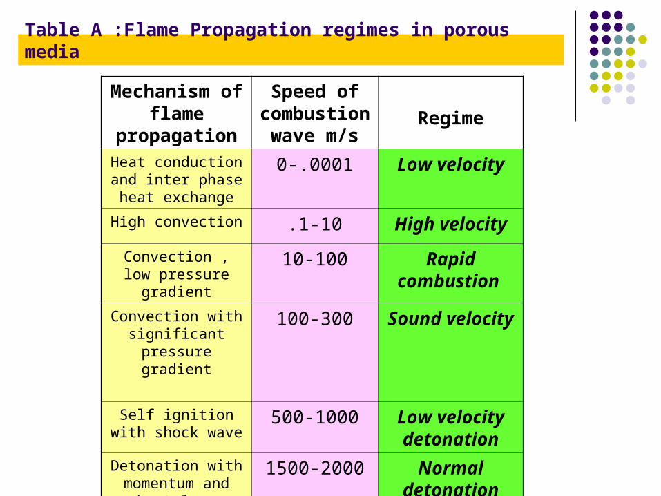
RegimeSpeed of
combustion wave m/s
Mechanism of flame
propagationLow velocity0-.0001Heat conduction and
inter phase heat exchange
High velocity.1-10High convection
Rapid combustion
10-100Convection , low pressure gradient
Sound velocity100-300Convection with significant pressure
gradient
Low velocity detonation
500-1000Self ignition with shock wave
Normal detonation
1500-2000Detonation with momentum and heat
loss
Table A :Flame Propagation regimes in porous media
Combustion in inert porous media is possible if:
•The modified Peclet-number defined with the typical diameter dmof the porous cavity size and the laminar flame velocity SL is highenough (>65), for methane /air mixtures.
•The combustion inside the porous medium is very intense and the reaction zone in the porous matrix has an elongated form with a length of several centimeters in the stream wise direction when using premixed natural gas with air under atmospheric pressure.
Possibilty Of Combustion In Porous Media

Materials for Porous Medium Combustion
It is a special feature of this technology that it is dependent on special high-temperature resistant porous components.
The most important material and forms for porous burners are:
SiC foams as well as mixer-like structures made of Al2O3 fibers, ZrO2 foams (can be used at temperatures above 1650°C). and C/SiC structures.
Iron-chromium-aluminum alloys and nickel-base alloys can be used. (Temperature resistant metal alloys may be used for temperatures below 1250°C).
Ceramic foams of different base materials are also used for porous burners. Independent on the base material such structures feature good conduction heat transport, a rather long start-up phase, low radiation heat transport properties, intermediate dispersion properties, and a relatively high pressure drop.
.
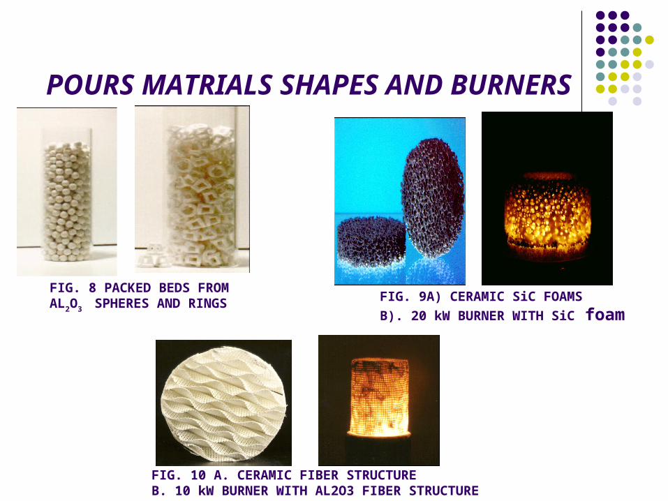
POURS MATRIALS SHAPES AND BURNERS
FIG. 8 PACKED BEDS FROM AL2O3 SPHERES AND RINGS FIG. 9A) CERAMIC SiC FOAMS
B). 20 kW BURNER WITH SiC foam
FIG. 10 A. CERAMIC FIBER STRUCTUREB. 10 kW BURNER WITH AL2O3 FIBER STRUCTURE
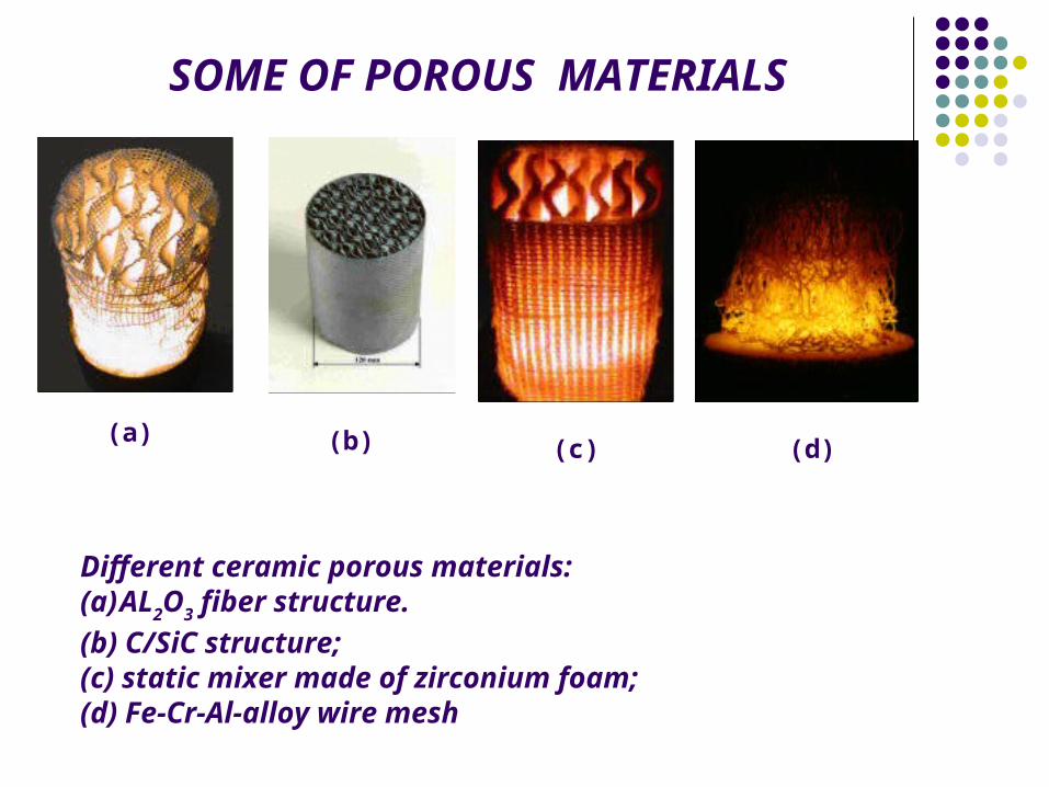
SOME OF POROUS MATERIALS
(a) (b) (c)
Different ceramic porous materials: (a)AL2O3 fiber structure.(b) C/SiC structure; (c) static mixer made of zirconium foam; (d) Fe-Cr-Al-alloy wire mesh
(d)
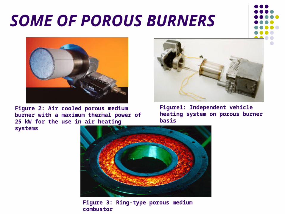
SOME OF POROUS BURNERS
Figure1: Independent vehicle heating system on porous burner basis
Figure 2: Air cooled porous medium burner with a maximum thermal power of 25 kW for the use in air heating systems
Figure 3: Ring-type porous medium combustor
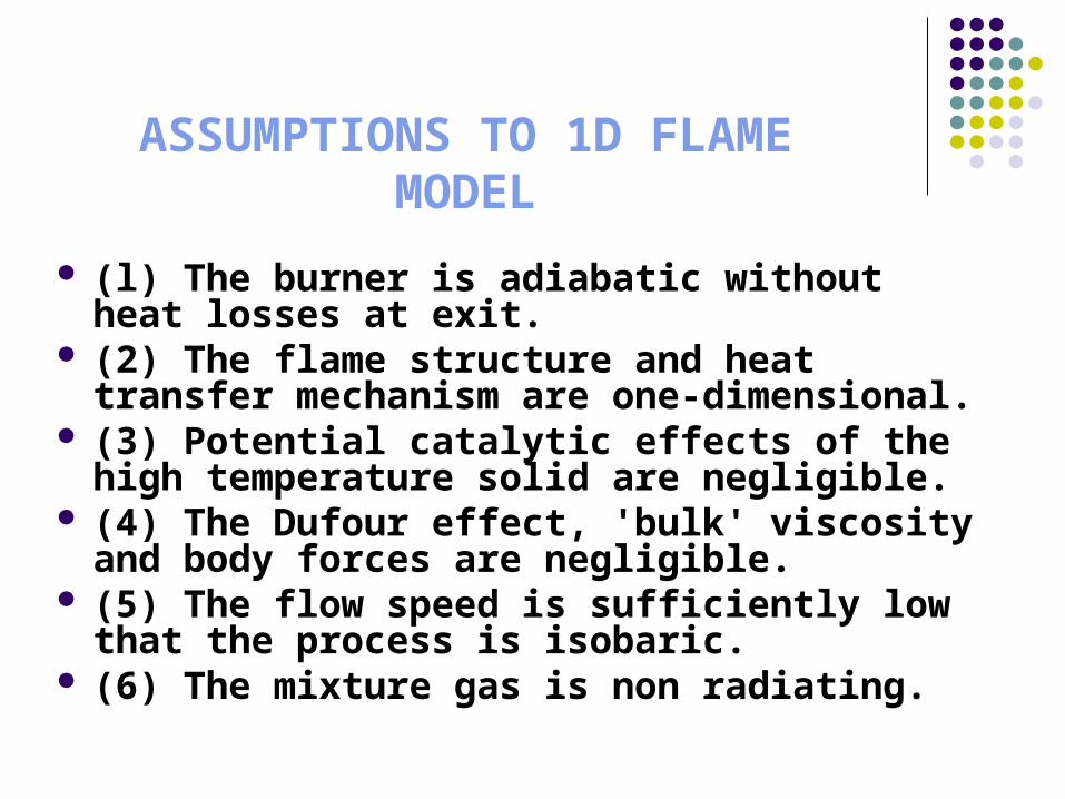
ASSUMPTIONS TO 1D FLAME MODEL
(l) The burner is adiabatic without heat losses at exit.
(2) The flame structure and heat transfer mechanism are one-dimensional.
(3) Potential catalytic effects of the high temperature solid are negligible.
(4) The Dufour effect, 'bulk' viscosity and body forces are negligible.
(5) The flow speed is sufficiently low that the process is isobaric.
(6) The mixture gas is non radiating.

PHYSICAL MODEL TO STUDY THE COMBUSTION IN NON HOMEGENOUS
POROUS MEDIA
Figure shows a schematic diagram of a one-dimensional physical model. It consisted of two porous ceramic cylinders stacked together and insulated around the circumference. The upstream and downstream ceramic cylinders were referred to as preheating region (PR) and the stable burning region (SBR).
The porous ceramic was a reticulated matrix that consisted ofalumina oxide (Al2O3). Pore densities as specified of l0 pores per
inch (PPI) was used for the SBR and the PR had 66 PPI. The unit porosity was 87% for l0 PPI and 83.4% for 66 PPI
The actual mean pore diameter was 1.52 mm for l0 PPI and 0.29 mm for 66 PPI length of PR was 5 cm, and the SBR was 10 cm.

THANK YOU VERY MUCH