Embed Size (px)
Citation preview

CO
REV
A F
YN -
FYHShell and tubes
Dry expansion evaporator
1HEAT PUMPS - AIR CONDITIONING - REFRIGERATION - AIR HANDLING - HEAT EXCHANGE - NA 13.584 A
Use
Description
QUick selection
This generation of shell and tubes evaporator has been designed for integration into high and medium power cooling systems.
Corrugated tubes for
enhanced heat transferRefrigerant grade components
range of optimised units
Cooling capacity : 50 to 3000 kW
Nota : The lubrification oil must be PERFECTLY MISCIBLE with the refrigerant fluid for the mentioned nominal conditions
To be used with all halogenised, zeotrope or azeotroperefrigerant fluids (R507, R134a, R404A, R407C...).The bundle tubes are of copper.
Low temperature : 316 L stainless steel shell
Adapted for the NH3 (R 717).The bundle tubes are of steel.
Low temperature and corrosive fluids : stainless steel 316 Lshell, tubular plates and tubes.
FYH
FYN bt FYH IN
FYN
WATER inlet Temp = 12 °CEvaporating temperature > 0 °C Superheating of gases 4 K
Temp. of fluid before expansion 35°C Fouling factor 0,00005 m2 °C/W
R404A NH3Power
kW FYNWaterflowm3/h
Water pressure dropkPa FYH
Waterflowm3/h
Water pressure dropkPa
100 168 20 4B 17 35 168 20 4B 16 34200 219 25 4B 39 45 219 25 4B 34 45300 273 20 4B 51 38 273 20 4B 51 50450 355 20 4B 77 23 273 30 4B 67 75600 355 25 4B 103 54 355 25 4B 103 32750 406 25 4B 129 50 406 25 4M 129 39
1000 457 30 4B 172 31 457 30 4B 172 281500 508 30 4B 257 47 558 40 4B 257 562000 660 40 4B 343 86 660 40 4B 343 67
HEAT PUMPS - AIR CONDITIONING - REFRIGERATION - AIR HANDLING - HEAT EXCHANGE - NA 13.584 A
COREVA FYN - FYH
2
Shell and tubesDry expansion evaporator
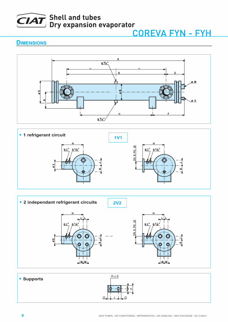
Dimensions
==
• 1 refrigerant circuit 1V1
2V2• 2 independant refrigerant circuits
R x S
O O
P
• Supports

CO
REV
A F
YN -
FYHShell and tubes
Dry expansion evaporator
3HEAT PUMPS - AIR CONDITIONING - REFRIGERATION - AIR HANDLING - HEAT EXCHANGE - NA 13.584 A
ModelsFYN - FYH
A B C D E F G H N I O P RXS 1V1 2V2J K J K L M
168 20 2128 168 240 1790 197 342 194 249 1500 70 35 60 8 x 17 52 60 − − − −219 20 2133 219 290 1780 204 344 220 275 1500 110 35 60 8 x17 65 75 65 76 40 40219 25 2633 219 290 2280 204 594 220 275 1500 110 35 60 8 x 17 65 75 65 76 40 40219 30 3133 219 290 2780 204 844 220 275 1500 110 35 60 8 x 17 65 75 65 76 40 40273 20 2144 273 355 1740 227 347 247 310 1500 110 35 60 8 x 17 72 97 78 100 48 40273 25 2644 273 355 2240 227 597 247 310 1500 110 35 60 8 x1 7 72 97 78 100 48 40273 30 3144 273 355 2740 227 847 247 310 1500 110 35 60 8 x 17 72 97 78 100 48 40355 20 2167 355 445 1720 244 354 288 355 1500 170 35 60 8 x1 7 100 135 89 126 62 62355 25 2667 355 445 2220 244 604 288 355 1500 170 35 60 8 x1 7 100 135 89 126 62 62355 30 3167 355 445 2720 244 854 288 355 1500 170 35 60 8 x1 7 100 135 89 126 62 62406 25 2672 406 495 2180 264 604 313 376 1500 230 35 60 8 x 17 − − 108 151 71 67406 30 3172 406 495 2680 264 854 313 376 1500 230 35 60 8 x 17 − − 108 151 71 67406 35 3672 406 495 3180 264 1104 313 376 1500 230 35 60 8 x 17 − − 108 151 71 67406 40 4172 406 495 3680 264 1354 313 376 1500 230 35 60 8 x 17 − − 108 151 71 67457 30 3217 457 550 2500 397 857 338 402 1500 230 35 60 8 x1 7 − − 125 175 100 55457 40 4217 457 550 3500 397 1107 338 402 2000 230 35 60 8 x 17 − − 125 175 100 55508 30 3242 508 610 2500 397 866 364 450 1500 230 35 60 8 x1 7 − − 130 190 95 70508 40 4242 508 610 3500 397 1116 364 450 2000 230 35 60 8 x1 7 − − 130 190 95 70558 30 3229 558 660 2594 343 888 425 475 1500 300 50 100 23 x 30 − − 150 210 105 75558 40 4229 558 660 3594 343 1138 425 475 2000 300 50 100 23 x 30 − − 150 210 105 75558 50 5229 558 660 4594 343 1138 425 475 3000 300 50 100 23 x 30 − − 150 210 105 75610 40 4315 610 715 3420 445 1155 455 530 2000 350 50 150 23 x 30 − − 178 210 110 105610 50 5315 610 715 4420 445 1155 455 530 3000 350 50 150 23 x 30 − − 178 210 110 105660 40 4325 660 765 3514 464 1123 474 520 2000 400 50 150 23x 30 − − 190 235 120 102660 50 5325 660 765 4514 464 1123 474 520 3000 400 50 150 23 x30 − − 190 235 120 102
711 40 4343 711 835 3444 503 1117 506 540 2000 400 50 150 23 x 30 − − 195 250 120 115
711 50 5343 711 835 4444 503 1117 506 540 3000 400 50 150 23 x 30 − − 195 250 120 115
Dimensions
Models
Connections FYN FYHRefrigerant dm3
WaterVolumes Weight Volumes Weight
1V1 2V2 Internal External Emptykg
Internal External Emptykgv w v w x dm3 dm3 dm3 dm3
168 20 7/8’’ 1’’5/8 − − G2’’1/2 16 19 93 14 21 110219 20 1’’1/8 2’’1/8 7/8’’ 1’’5/8 G3’’ 28 35 138 26 33 177219 25 1’’1/8 2’’1/8 7/8’’ 1’’5/8 G3’’ 35 44 159 33 41 208219 30 1’’1/8 2’’1/8 7/8’’ 1’’5/8 G3’’ 42 53 179 40 49 237273 20 1’’5/8 2’’5/8 1’’1/8 2’’1/8 DN100 47 55 228 42 51 285273 25 1’’5/8 2’’5/8 1’’1/8 2’’1/8 DN100 59 69 259 52 64 330273 30 1’’5/8 2’’5/8 1’’1/8 2’’1/8 DN100 71 83 287 62 77 373355 20 2’’1/8 3’’1/8 1’’5/8 2’’5/8 DN125 81 94 401 72 85 502355 25 2’’1/8 3’’1/8 1’’5/8 2’’5/8 DN125 102 117 452 90 106 577355 30 2’’1/8 3’’1/8 1’’5/8 2’’5/8 DN125 122 140 503 108 128 653406 25 − − 1’’5/8 3’’1/8 DN150 136 156 574 116 143 730406 30 − − 1’’5/8 3’’1/8 DN150 164 188 636 140 172 824406 35 − − 1’’5/8 3’’1/8 DN150 191 219 697 163 201 917406 40 − − 1’’5/8 3’’1/8 DN150 219 251 760 186 230 1010457 30 − − 1’’5/8 4’’1/8 DN200 206 231 845 156 222 1180457 40 − − 1’’5/8 4’’1/8 DN200 273 308 1125 208 299 1479508 30 − − 1’’5/8 4’’1/8 DN200 245 271 977 194 276 1475508 40 − − 1’’5/8 4’’1/8 DN200 327 374 1215 259 370 1836558 30 − − 1’’5/8 4’’1/8 DN200 309 331 1396 − − −558 40 − − 1’’5/8 4’’1/8 DN200 408 445 1694 314 427 2392558 50 − − 1’’5/8 4’’1/8 DN200 507 560 1992 393 536 2865610 40 − − 2’’1/8 4’’1/8 DN250 508 541 1905 380 531 2741610 50 − − 2’’1/8 4’’1/8 DN250 628 680 2203 475 667 3248660 40 − − 2’’1/8 168.3 DN250 586 625 2394 454 586 3422660 50 − − 2’’1/8 168.3 DN250 725 786 2783 568 737 4068711 40 − − 2’’1/8 168.3 DN300 718 694 2926 529 683 4089711 50 − − 2’’1/8 168.3 DN300 889 872 3377 661 859 4831
ConneCtions − CapaCities − weight

HEAT PUMPS - AIR CONDITIONING - REFRIGERATION - AIR HANDLING - HEAT EXCHANGE - NA 13.584 A
COREVA FYN - FYH
4
Shell and tubesDry expansion evaporator
teChniCal data
operating limits
(1) High performance corrugated tube bundle secured by flanging on 2 steel tubular plates (2).
(3) Casing equipped with :− External circuit inlet/outlet tubes (4) (5), each equipped with a 1” connector for instrumental devices− 3/4” connectors for drainage of the external circuit tubing− Support feet
(6) Set of gaskets between :− Plug (7) and insert (8),− Insert and tubular plate,NOTE : The refrigerant circuit connectors are fitted on the front plug.
(9) Anti-corrosion baffles.
UnitCircuit inside core Circuit outside core
Coolant PS Liquid PS
Evaporators COREVAFYN −40 / 50 °C
20 b
−20 / 50 °C
10 b
Evaporators COREVAFYH −16 / 50 °C −16 / 50 °C
Evaporators COREVAFYN “low T° ” −40 / 50 °C −40 / 50 °C
Evaporators COREVAFYH “low T° ” −40 / 50 °C −40 / 50 °C
PS : Maximum allowable pressure
Standard
On request
POSITION P11
POSITION P33
water inlet andoutlet at the leftside
water inlet andoutlet at theright side
This document is non-contractual. As part of its policy of continual product improvement, CIAT reserves the right to make any technical modification it feels appropriate without prior notification.
Head office Avenue Jean Falconnier - B.P. 1401350 - Culoz - FranceTel.: +33 (0)4 79 42 42 42Fax: +33 (0)4 79 42 42 [email protected] - www.ciat.com
Compagnie Industrielle d’Applications Thermiques - S.A. with a registered capital of 26 728 480 € - R.C.S. Bourg-en-Bresse B 545 620 114
CIAT ServiceTel. : 08 11 65 98 98 (0,15 € / mn)Fax : 08 26 10 13 63 (0,15 € / mn)