Embed Size (px)
Citation preview
A-A&07 454 NAVAL POSTGRADUATE SCHOOL. MONTEREY CA F/0 13/1DESIGN M DOEL FOR THE HEAT TRANSFER IN A SHORT STRAIGHT TUBE SOI-ETC(UJJUN31 81 L W VOLLMER
UNCLASSIFIED N6
I~o uIuuuoilumoIIIIIIIIIIIIllllllllllllIIIIIIIIIIIIIIIIm
1 401.0.8
111L25 ~ - 1162IIII _IIII liiIII
MICROCOPY RESOLUTION TEST CHART
NATIONAL URIA N Il I I ARO- '.bl A

... .. .. ..... . I .. .L - -IE I i. . .- , " -i
cPOONAVAL POSTGRADUATE SCHOOLMonterey, California LEVEL-
DTICELECTE
NOV 19 1981
THESIS DDESIGN MODEL FOR THE HEAT TRANSFER
IN A SHORT STRAIGHT TUBE BOILER
by
Leo W. Vollmer, Jr.
June 1981
Thesis Advisor: P.F. Pucci
Approved for public release; distribution unlimited.
L 03

UnclassifiedsECUmITy CLASSIICATIOW OP Toins PAGE I1 000 Be
REPORT DOCUMENTATION PAGE RAD COMPTIUCNG NSlawn --Ft. GOVT AG3SO NO 4. jitsNT S CATALOG NUMERn
- ~i ?sters esis( Design Model for the Heat Transfer in a Short,, :
Straight Tube Boiler ... Me" i6. PERFORMING 000. REPORNT NUMR
j* ~6. CONTRACT OR GRANT MUMS901(sI
Leo W. (Vollmer, Jr/
S. PerPORullN ORGANIZATION NAME ANO AOOnU 10. PROGRAM ELE"MENT. PRJET. TAlE
AREA A WORK UNIT NUSERleS
Naval Postgraduate SchoolMbnterey, California 93940
I,. CONTROLLING OFFICE NAME ANO AoRSS ,.#-- T
Naval Postgraduate School is UM Junso lr1Monterey, California 93940 iS , /2ME P- ., -
I4. MONITONING AGENY NAME & ACORCSNSIl 01"0001 "M Ce"I"lld *OO) IS. S9CUrrV*CLAwZwr M5W)
Unclassified-"a OECL ASI PICATIONIOOWNGRAOING
SCNEDULE
S. DISTRIBUTION STATEMENT (oe roj RQPeM)
Approved for public release; distribution unlimited.
I?. OISTRIBUTION STATEMENT (of to 4a9~ed eMJod g* Wgeek ". Ii 4001 h RepU)
IS. SUPPLEMENTARY NOTES
19. KE9Y WORDS (CUM - ,,On * ee ,jr W ee it 11 old 1.4NM11110 6y 680041 011160)
.aste heat recoveryShort straight tube boilerStagnation boilerBoiling heat transfer
20. ABSTRACT (COM10 40 POY Sie It R0""W da iPAify a? moo&1 MINO
,.A design model for the Short Straight Tube Boiler with a segmented fin-tubearrangement was developed. This model was integrated for a single tube appliedin a computer program written in BASIC for the Hewlett Packard 9845 model Bdesk-top computer.
Water-side Reynolds numbers were varied in order to investigate the per-formance of this boiler. For an overall tube length of 39.4 inches, a Reynoldsnumber of 840 (29.65 lbm/hr) resulted in obtaining 50* superheat for anO "o" 1473 am'noN of, Iol o is o00OOL-6?
,A , Unclassified/ 0SECUNITY CLAIFICATIOI OP TRIS P -- ,I-M-. -awe

" Incasified
- __
"-operating pressure of 600 psig. With these conditions, saturated boilingbegins at 11.45 inches and superheating at 21.88 along the tube length.
Acces sion Fo"r/ACOS~lFor / --
NTIS GRA&I -
DTIC TAB [lUnannounced QJustificat ion
Distribution/Availability Codes
Avail and/or -
Dist special
DD aorD 1403 Unclassifiedi - ... . . . . ." ". 2 4&&wP4 AYW .. . . P_6-U,,a. .PM$ ,U"#6-
Approved for public release; distribution unlimited.
Design Model for the Heat Transferin a Short Straight Tube Boiler
by
Leo W. Vollmer, Jr.Lieutenant, United States NavyB.S.E.E. Purdue University, 1974
Submitted in partial fulfillment of therequirements for the degree of
MASTER OF SCIENCE IN MECHANICAL ENGINEERING
from the
NAVAL POSTGRADUATE SCHOOL
June 1981
Author: & .Z
Approved by:
CO-Avisor/Second Re-a Xe-
Dean of Science and Engineering
.i3
ABSTRACT
A design model for the Short Straight Tube Boiler with a
segmented fin-tube arrangement was developed. This model
was integrated for a single tube and applied in a computer
program written in BASIC for the Hewlett Packard 9845 model
B desk-top computer.
Water-side Reynolds numbers were varied in order to in-
vestigate the performance of this boiler. For an overall
tube length of 39.4 inches, a Reynolds number of 840 (29.65
lbm/hr) resulted in obtaining 50 superheat for an operating
pressure of 600 psig. With these conditions, saturated boil-
ing begins at 11.45 inches and superheating at 21.88 along
the tube length.
4

TABLE OF CONTENTS
I. INTRODUCTION --------------------------------------15
A. BOILER -----------------------------------------1
1. An Overview ------------------------------- is
2. History ----------------------------------- 16
3. Boiler Types-------------------------------21
a. Fire-Tube Boilers----------------------22
b. Water-Tube Boilers---------------------31
4. Water Circulation ------------------------- 50
S. Heat Source--------------------------------527
B. RACER AND THE SST ----------------------------- 54
C. OBJECTIVE -------------------------------------- 8
I. MODEL DESCRIPTION ---------------------------------60
A. AN OVERVIEW -----------------------------------60
B. GEOMETRY --------------------------------------64
1. Segmented Fins-----------------------------65
2. Pin Fins-----------------------------------65
C. GAS-SIDE HEAT TRANSFER/PRESSURE DROP ---------- 70
D. WATER-SIDE HEAT TRANSFER -------------------- 7
E. OVER-ALL HEAT TRANSFER ------------------------ 84,
II.RESULTS AND CONCLUSIONS----------------------------90
A. BACKGROUND ------------------------------------90
B. DESIGN VARIABLES-------------------------------91
1. S.S.T. operating Pressure------------------92
S
2. Frontal Diminsions ---------------------- 92
3. Gas Flow Rate and Temperatures ---------- 92
4. Superheater Outlet Steam Temperature 92
5. Water Inlet Temperature ----------------- 92
6. Fin Geometry ----------------------------- 92
C. THE DATA SET -------------------------------- 93
D. CONCLUSION ---------------------------------- 108
IV. RECOMMENDATIONS FOR FURTHER RESEARCH ------------ 136
APPENDIX A: PROGRAM{ LISTING -------------------------- 138
LIST OF REFERENCES ----------------------------------- 178
INITIAL DISTRIBUTION LIST ------------------------------ 181
6

LIST OF FIGURES
FIGURE 1: BRONZE WATER-COOLED TUBES AND WATER-COOLEDFURNACE CHAMBER WALL ----------------------- 17
FIGURE 2: THOMAS SAVERY'S FIRST BOILER - 1698 -------- 22
FIGURE 3: THOMAS SAVERY'S IMPROVED BOILER - 1702 ----- 23
FIGURE 4: DR. DESAGULIER'S WINDING FLUE BOILER -1718 --------------------------------------- 24
FIGURE 5: HAYSTACK BOILER - 172S --------------------- 25
FIGURE 6: JAMES WATTS WAGON-TYPE BOILER - 1795 ------- 25
FIGURE 7: CYLINDRICAL BOILER - 1790 ------------------ 26
FIGURE 8: OLIVER EVAN'S RETURN-FLUE BOILER - 1800 27
FIGURE 9: RICHARD TREVITHICKS' CORNISH BOILER -------- 28
FIGURE 10: VERTICAL BOILER TYPES ---------------------- 29
FIGURE 11: FIRST WATER-TUBE BOILER - 1766 ------------- 32
FIGURE 12: BOX-SHAPE WATER-TUBE BOILER - 1793 --------- 33
FIGURE 13: JOHN STEVEN'S PORCUPINE BOILER - 1804 ------ 33
FIGURE 14: JOHN COX STEVENS' WATER-TUBE BOILER -
1805 - ---------------------------------------34
FIGURE 15: THE FIRST SECTIONAL WATER-TUBE BOILER -JOSEPH EVE - 1825 -------------------------- 35
FIGURE 16: GOLDWORTHY GURNEY'S CARRIAGE BOILER -
1826 --------------------------------------- 36
FIGURE 17: STEPHEN WILCOX'S BOILER WITH INCLINEDTUBES - 1856 ------------------------------- 37
FIGURE 18: FIRST SECTIONAL WATER-TUBE BOILER WITHINCLINED TUBES -TWBILL - 1865 -------------- 37
FIGURE 19: SIDE VIEW OF HEADER-TYPE BOILER ------------ 40
FIGURE 20: BASIC "A t TYPE BOILER ---------------------- 42
7
Adi-"-

FIGURE 21: YARROW TYPE BOILER ------------------------- 43
FIGURE 22: "A" TYPE BOILER WITH UNCONTROLLED INTEGRALSUPERHEAT ---------------------------------- 43
FIGURE 23: SECTIONAL EXPRESS TYPE BOILER - 1939 ------- 44
FIGURE 24: SEPARATELY FIRED SUPERHEATER BOILER -1930 --------------------------------------- 44
FIGURE 25: "A" TYPE BOILER FOR GENERATINGSUPERHEATED STEAM WITH CONTROLLED,INTEGRAL, INTERDECK SUPERHEAT -------------- 45
FIGURE 26: "M" TYPE BOILER WITH CONTROLLED,
INTEGRAL SUPERHEATER ----------------------- 46
FIGURE 27: MODIFIED "A" OR GUEST BOILER --------------- 47
FIGURE 28: "D" TYPE BOILER ---------------------------- 48
FIGURE 29: NEWER 1200 PSIG SINGLE-FURNACE BOILERFOR POST WORLD WAR II DESTROYERS ----------- 49
FIGURE 30: THE "BENSON" BOILER ------------------------ 51
FIGURE 31: SCHEMATIC DIAGRAM OF CONTROLLED
CIRCULATION BOILER ------------------------- 53
FIGURE 32: SHORT STRAIGHT-TUBE BOILER UNIT ------------ 57
FIGURE 33: SEGMENTED FIN PROFILE ---------------------- 66
FIGURE 34: PIN FIN PROFILE ---------------------------- 67
FIGURE 35: MODEL TUBE LAYOUT -------------------------- 69
FIGURE 36: HEAT TRANSFER CONSTANTS ---------------------- 71
FIGURE 37: SURFACE HEAT FLUX VS. INLET SUBCOOLING ----- 75
FIGURE 38: METHOD OF ROHSENOW ------------------------- 77
FIGURE 39: TWO-PHASE FLOW DEVELOPMENT ----------------- 79
FIGURE 40: SUPPRESSION FACTOR, S ---------------------- 91
FIGURE 41: WATER MASS FLOW VS. REYNOLDS NO. ------------- 94
FIGURE 42a: SUPERHEAT VS. REYNOLDS NO. ------------------ 96
FIGURE 42b: STEAM MASS FLOW VS. SUPERHEAT -------------- 97
8
FIGURE 43: REYNOLDS NO. = 310--------------------------- 98
FIGURE 44; REYNOLDS NO. - 300--------------------------- 99
FIGURE 45: REYNOLDS NO. - 310---------------------------- 100
FIGURE 46: REYNOLDS NO. = 380---------------------------- 101
FIGURE 47: REYNOLDS NO. = 310---------------------------- 102
FIGURE 48: REYNOLDS NO. = 380---------------------------- 103
FIGURE 49: LOCATION OF ZERO% QUALITY-------------------- 104
FIGURE 50" LOCATION OF 100% QUALITY--------------------- 105
FIGURE Sia: REYNOLDS NO. = 840---------------------------- 109
FIGURE Sib: REYNOLDS NO.= 840---------------------------- 110
FIGURE Sic: REYNOLDS NO. = 840---------------------------- 111
FIGURE 52a: REYNOLDS NO. = 840---------------------------- 112
FIGURE 52b: REYNOLDS NO. - 840---------------------------- 113
FIGURE 52c: REYNOLDS NO. = 840---------------------------- 114
FIGURE 53a: REYNOLDS NO. = 840---------------------------- 115
FIGURE 53b: REYNOLDS NO. = 840---------------------------- 116
FIGURE 53c: REYNOLDS NO. = 840---------------------------- 117
FIGURE 54a: REYNOLDS NO. = 840---------------------------- 118
FIGURE S4b: REYNOLDS NO. = 840---------------------------- 119
FIl;URE 54c: REYNOLDS NO. = 840---------------------------- 120
FIGURE 55a: REYNOLDS NO. - 840---------------------------- 121
FIGURE SSb: REYNOLDS NO. = 840---------------------------- 122
FIGURE 55c: REYNOLDS NO. = 840---------------------------- 123
FIGURE 55d: REYNOLDS NO. = 840---------------------------- 124
FIGURE 56a: REYNOLDS NO. - 840---------------------------- 125
FIGURE 56b: REYNOLDS NO. - 840---------------------------- 126
9
F IGU E S c : R YNO DS N .= 840 --- ---- --- ---- --- 1 2FIGURE 56d: REYNOLDS NO. - 840-------------------------- 127
FIGURE 57a: REYNOLDS NO. = 840-------------------------- 129
FIGURE S7a: REYNOLDS NO. - 840-------------------------- 129
FIGURE 57b: REYNOLDS NO. = 840-------------------------- 130
FIGURE 58a: REYNOLDS NO. = 840-------------------------- 131
FIGURE 58b: REYNOLDS NO. - 840-------------------------- 132
FIGURE 58b: REYNOLDS NO.= 840-------------------------- 133
FIGURE 59b: REYNOLDS NO.- 840-------------------------- 134
10
LIST OF TABLES
Table I. HEAT BALANCE RESULTS ----------------------- 106
Table 2. TUBE/FIN DIMENSIONS AND AREAS -------------- 107
11
- _ _ _ __- - 7

NOMENCLATURE
English Letter Symbols
A - Area (FT2)
Ab - Frontal Area Blocked by Tubes and Fins (FT2)
Abt - Bare Tube Area (FT2)
Af - Heat Exchanger Frontal Area (FT2)
Afin - Fin Area (FT2)
Aff - Cross-Sectional Area for Fluid Flow (FT2)
Amin - Minimum Cross-Sectional Area for Gas Flow (FT2)
As- Inside Heat Transfer Area (FT2 )
A - Outside Heat Transfer Area
Cmax Maximum Heat Capacity (BTU/Hr-F)
Cmin - Minimum Heat Capacity (BTU/Hr-F)
Cpf - Specific Heat of Water/Steam (BTU/lbm-F)
C - Specific Heat of Gas (BTU/lbm-F)pg
df - Fin Outside Diameter (FT)d - Inside Tube Diameter (FT)
d
d - Outside Tube Diameter (FT)
D - Pin Outside Diameter (FT)p
- Friction Factor
F - Reynolds Number Factor
Gmax - Maximum Gas Flow Rate Per Square Foot (lbm/hr-FT 2)
h - Heat Transfer Coefficient (BTU/Hr-FT 20 F)
Hps - Horizontal Pin Spacing (FT)
12

- Enthalpy (BTU/lbm)
If - Enthalpy of Saturated Water (BTU/lbm)
Ifs - Enthalpy of Vaporization (BTU/lbm)
j - Heat Transfer Colburn j-Factor
k - Thermal Conductivity of Gas (BTU-Hr-FT-F)
X - Fin Height (FT)
Zc - Length of Cut from Fin Tip (FT)
Lp - Average Pin Length (FT)
LT - Tube Length (FT)
N, NTU - Number of Transfer Units
Nf - Number of Fins Per Inch
Ns - Number of Segments in One Fin
OONB - Heat Flux to Initiate Boiling (BTU/Hr-FT2)
P - Pressure (psia)
Q - Heat Transfer Rate (BTU/Hr)
Ri - Heat Exchanger Inside Resistance (Hr-FT20 F/BTU)1
R0 - Heat Exchanger Outside Resistance (Hr-FT20F/BTU)
Rth - Thermal Resistance (Hr-FT2 -F/BTU)
T f - Fin Thickness (FT)
T - Gas Temperature (OF)
T sa - Temperature of Saturated Water (F)
TTO - Outside Tube Wall Temperature (OF)
TTi - Inside Tube Wall Temperature (*F)
Uoi, U0 - Overall Heat Transfer Coefficient (BTU/Hr-FT2 -F)
V - Vertical Pin Spacing (FT)
13
x - Steam Quality
Xe - Equilibrium Quality
XT - True Quality
XTT - Martinelli Parameter
Dimensionless Groups
Nu - Nusselt Number
Pr - Prandtl Number
Re - Reynolds Number
ReTp - Two-Phase Reynolds Number
St - Stanton Number
Greek Letter Symbols
a - Water Surface Tension (lbf/FT)
- Void Fraction
AP - Pressure Change (psia)
AT - Temperature Change (F)
C - Effectiveness
1b - Viscosity at Bulk Temperature (Ibm/FT-Hr)
Uw - Viscosity at Tube Wall Temperature (ibm/FT-Hr)
1 - Fin Efficiency
ns - Surface Efficiency
P - Density (lbm/FT 3)
- Density of Saturated Water (lbm/FT3)
- Density of Saturated Vapor (lbm/FT 3)
14
I. INTRODUCTION
A. BOILER
1. An Overview
A boiler is an apparatus in the form of a closed
vessel constructed for the continuous generation of vapor
under pressure through the transference of heat to the liquid
which is contained in it. The energy for most boilers is pro-
vided by the combustion of the fossil fuels - coal, oil, coke,
or gas. Coal is the major fuel, but most boilers are conver-
tible from one fuel to another. Other fuels such as wood,
waste gases from industrial processes, and solid wastes such
as bagasse (from sugarcane), sawdust, and even trash and gar-
bage serve as energy sources. An increasing number of large
steam plants built since 1960 for generating electricity are
designed to use nuclear fuel, which provides heat from nuclear
fission.
The simple term "boiler" ordinarily refers to the
steam boiler which utilizes available heat energy to convert
water into steam. Because a boiler produces saturated steam
only, it must be distinguished from the steam generator which
may include a superheater, economizer, and air preheater as
integral and necessary parts of the equipment. In their
simplest form, boilers are closed caldrons of water placed
over an open fire. Boilers range in size and function from
i5

the compact units in domestic heating systems to 20-story
complexes that drive giant steam turbines for electrical power
production. They are bu'ilt in many forms with rated steaming
capacities from 40 lbm/hr to 1,000,000 lbm/hr steam production
and operating pressures ranging from 2 psia to the critical
pressure of water, 3208 psia.
2. History
The development of the boiler was initiated and has
been sustained by the development of the steam engine and
steam turbine. Early versions of both, more toys than serious
inventions, are referred to in the writings of Hero of Alex-
andria during the third century B.C. Contrary to popular
belief, the principles used in boiler design are not recent
developments but are of ancient origin. As early as 200 B.C.,
boilers were employed for warming water, heating, and house-
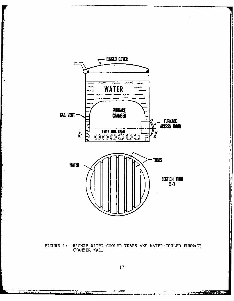
hold services. An example of this type of boiler is shown in
Fig. 1. In this boiler, found in the ruins of Pompeii, the
grate consisted of bronze water-cooled tubes and a water-cooled
furnace chamber wall. The boiler was internally fired, a
feature which did not appear again until the early 18th century.
Water-cooled furnaces and water tubes also were innovations
not incorporated in boiler design until recent.
However, basic principles for boiler construction,
comparable to those set down in 1769 by James Watt for the
steam engine, were not widely known until the 19th century.
Beginning with Hero, the caldron form of boiler was used.
16
HINGED wOB
TWATER
fooooo
WATER
SECTION ToRDX-X
FIGURE 1: BRONZE WATER-COOLED TUBES AND WATER-COOLED FURNACECHAMBER WALL
17
It was not until the latter part of the 17th century that
boilers in a real sense appeared on the scene. During this
period, the greatest potential use for power seemed to be
pumping water out of mines, and a number of engines were in-
vented for this purpose.
These pumping engines, from those first successfully
pioneered by Thomas Savery in 1699, to the engine patented
in 1769 by James Watt, were not true steam engines, but atmos-
pheric engines. Steam was used to fill a cylinder in which a
piston was mounted. When the steam was suddenly condensed by
a spray of water, a partial vacuum was created, and the piston
was forced down by atmospheric pressure. The steam pressure
that raised the piston, with the help of a counterweight on
each cycle of operation, was only slightly above atmospheric
pressure. The steam pressure was so low that without the
counterweight the piston would not have moved. Consequently,
the boilers for these engines were of relatively simple design.
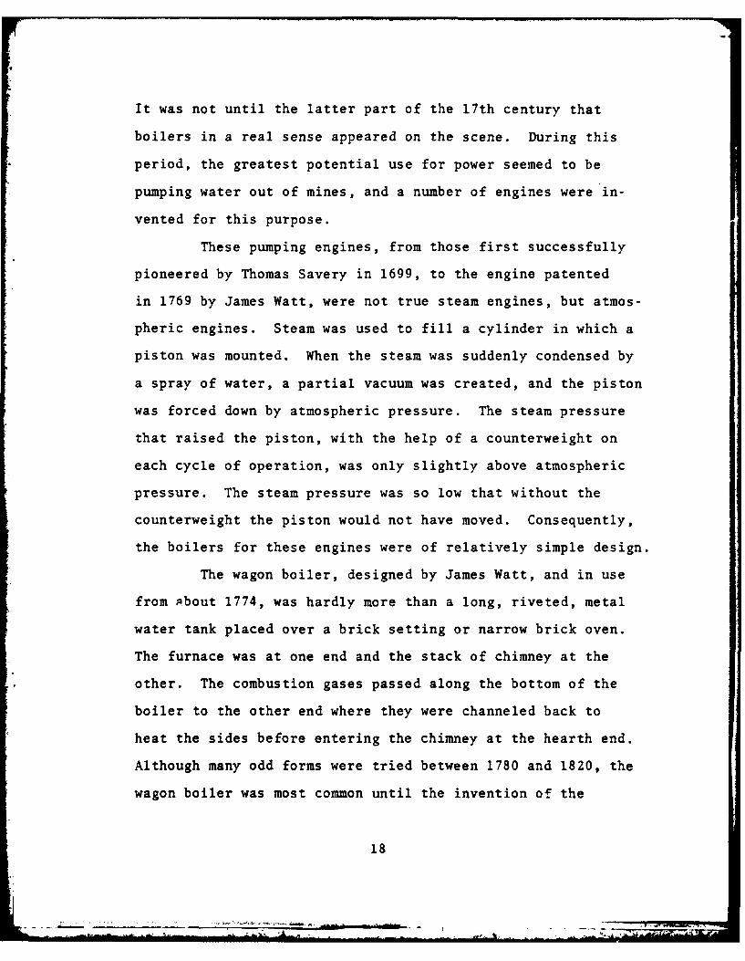
The wagon boiler, designed by James Watt, and in use
from about 1774, was hardly more than a long, riveted, metal
water tank placed over a brick setting or narrow brick oven.
The furnace was at one end and the stack of chimney at the
other. The combustion gases passed along the bottom of the
boiler to the other end where they were channeled back to
heat the sides before entering the chimney at the hearth end.
Although many odd forms were tried between 1780 and 1820, the
wagon boiler was most common until the invention of the
18

internal flue by Oliver Evans in the United States and, inde-
pendently, between 1800-1805 by Richard Trevithick in England.
In true steam engines, where steam does mechanical work,
it is advantageous to impart the highest pressure possible to
the steam before it is released into the pressure cylinder.
Both Evans and Trevithick saw the necessity of high pressure
engines for marine and locomotive applications and were chiefly
responsible for the adoption of higher steam pressures. Built
in two forms, the boiler was a long cylindrical shell with a
large internal cylindrical tube. In one form the flue contained
a furnace at one end and opened to a stack at the other. In
the second a brick setting was used. Hot gases from the fur-
naces were drawn through the setting, heating the lower surface
of the shell, and then returned through the internal flue to
the stack above the furnace.
With the addition of a number of small internal flues,
called fire tubes, operating pressures increased rapidly. The
usual pressure in the time of Watt was only S-7 psi above
atmospheric. Evans, Trevithick, and John Stevens of New York
early in the 19th century used pressures from 50-75 psia.
Jacob Perkins of Massachusetts, in work done between 1823 and
1827, actually obtained 1400 psia. But in general, fire-tube
boilers are limited to relatively low operating pressures
because of the difficulty of constructing a shell strong enough
to withstand the high pressure required for efficient operation.
As pressure demands of steam engines and turbines increased,
19

the fire-tube boiler was supplemented by the water-tube boiler.
During the 1820's, steam pressures on the Mississippi steam-
boats and elsewhere in the United States had been raised to
100 and 150 psia, but explosions were frequent.
It was early recognized that the strength requirements
for increased pressure could be met if the tubes contained the
water rather than the hot gases. Two problems impeded the
development of the water-tube boiler. First, adequate circu-
lation of the water within the tubes had to be maintained in
order to absorb the heat transferred through the tube wall.
Without this circulation the tube-wall temperature and the tube
would be burnt! out. A second difficulty was the explosion
hazard of higit pressure operation where relatively large
amounts of wr-ir are in contact with heating surfaces liable
to fail bicause of overheating. In the event of such failure,
liquid water, at the saturation temperature corresponding to
a high pressure, flashes to steam with explosive force. If,
however, the total amount of water in a boiler flows in a
sufficient number of parallel circuits, as in a sectioned
boiler, a failure in the heating surface will not be serious.
Although these problems were recognized by Joseph Eve and
Goldsworth Gurney in 1825 and 1826, the only successful water-
tube boiler prior to 1870 was that patented by Babcock and
Wilcox in 1867.
The period from 1870 to 1900 was one of improvements.
The multiple drum bent-tube (Stirling) boiler, successfully
20
introduced in 1893 is actually the most recent form of boiler
construction. Subsequent improvements in materials and methods
of construction increased the steaming capacity of the largest
central power plant boilers from 30,000 lbm/hr in 1905 to
1,000,000 lbm/hr by 1935. In 1926, Iving Moultrop was respon-
sible for the increase in operating pressures from 350 to 1200
psia. By 1935 this pressure had gone to 1600 psia. Modern
plants are built to operate above critical temperature at
4500 to 5000 psia. The steam generator superheat temperatures
have likewise increased from a maximum of 550*F in 1905 to
750*F in 1925 and 950*F in 1938. Moder'n plants are designed
to operate at 1050OF to 1100 0 F.
3. Boiler Types
There are basically two types of boilers: fire-tube
and water-tube boilers. All boilers that restrict the passage
of the hot gases through flues or tubes where they transfer
their heat to the surrounding liquid are called fire-tube
boilers. In the water-tube boiler the flue gases pass over
the exterior surface of the tubes while the water being heated
passes within the tube. Another distinguishing feature between
these two types of boilers is that the fire-tube boiler is
supported by the setting sidewalls or the fire box and the
water-tube boiler is usually suspended from the overhead steel
work and columns.
21
- z

a. Fire-Tube Boilers
Figures 2 to 10 show a historical development
of the fire-tube boiler from the first boiler used by Savery
in 1698 to the famous Cornish boiler designed by Trevithick.
FIGURE 2: THOMAS SAVERY'S FIRST BOILER - 1698
22
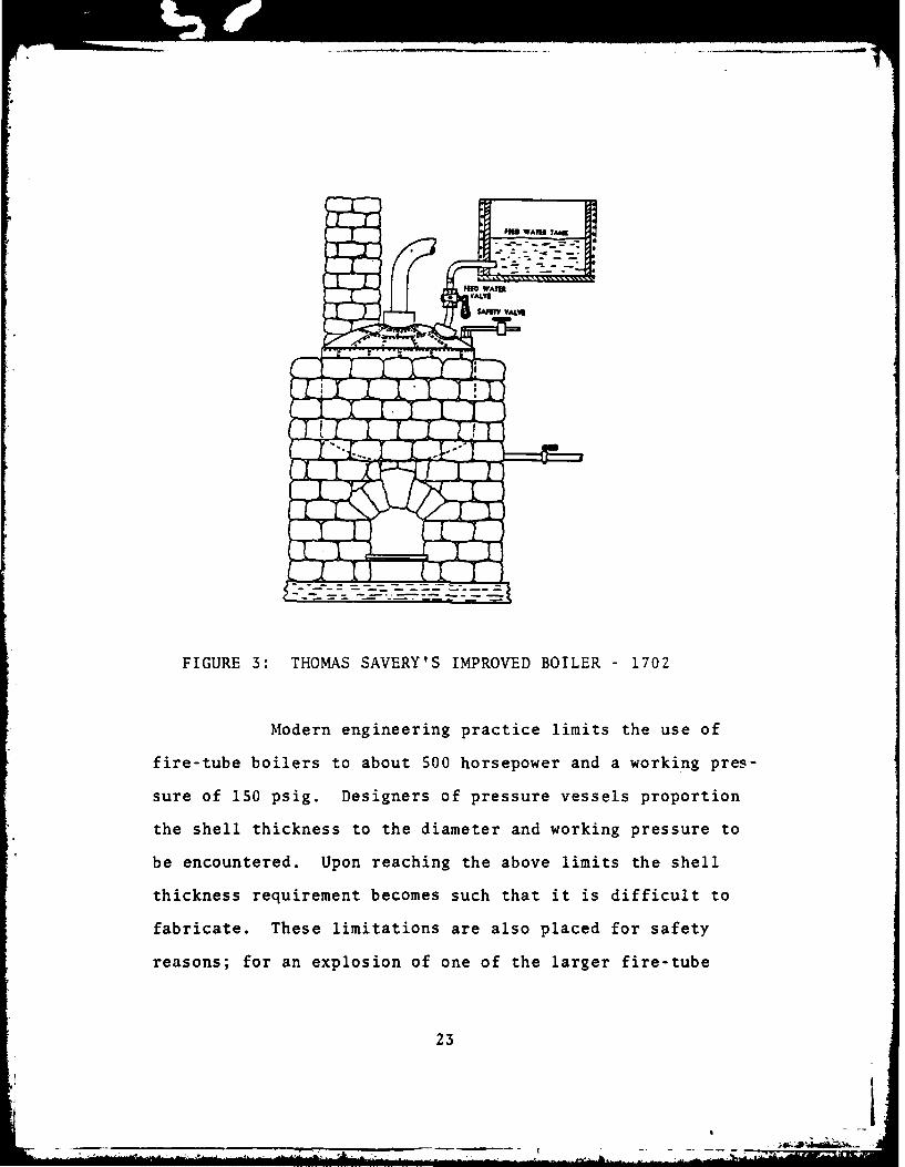
FIGURE 3: THOMAS SAVERY'S IMPROVED BOILER - 1702
Modern engineering practice limits the use of
fire-tube boilers to about 500 horsepower and a working pres-
sure of 150 psig. Designers of pressure vessels proportion
the shell thickness to the diameter and working pressure to
be encountered. Upon reaching the above limits the shell
thickness requirement becomes such that it is difficult to
fabricate. These limitations are also placed for safety
reasons; for an explosion of one of the larger fire-tube
23
AI
,~ ~ ~ ~ ~ ~ ~ ~ ~~ ~&R , -. .i .i .-- o o' .. -'''-
./
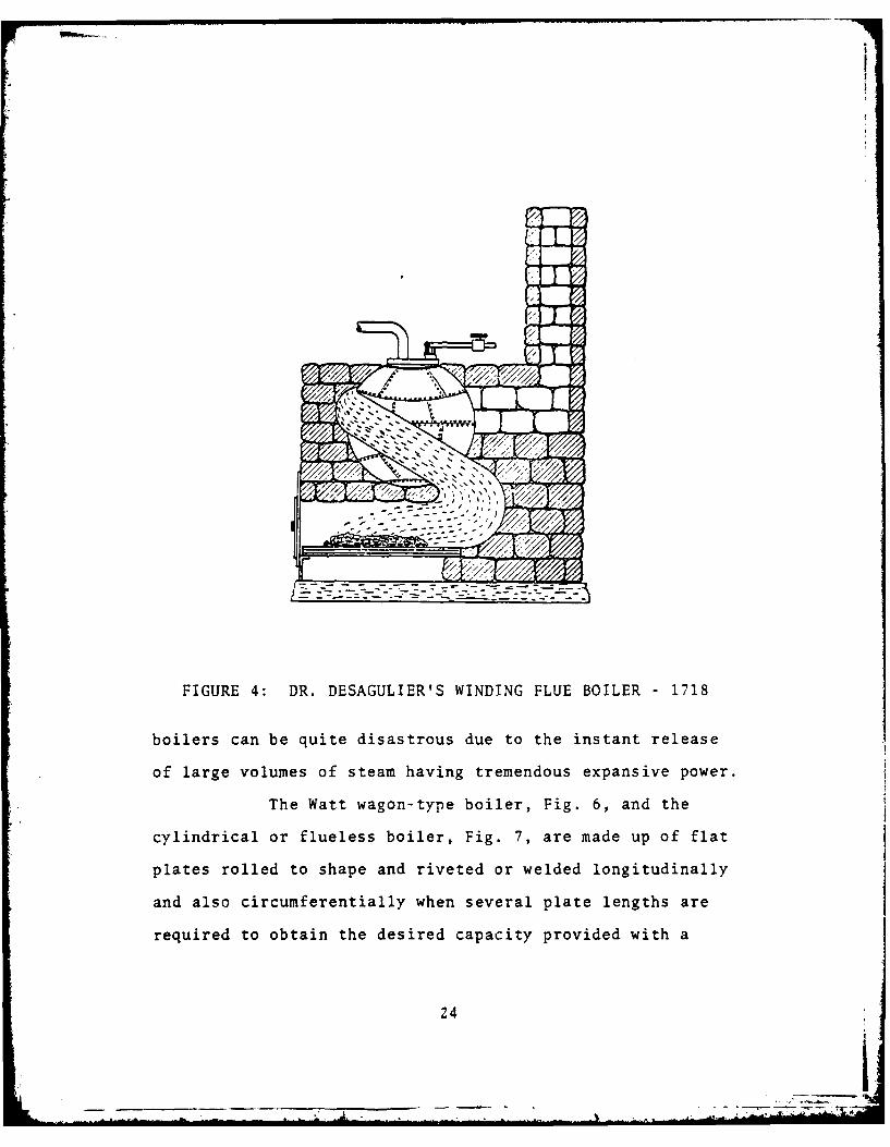
FIGURE 4: DR. DESAGULIER'S WINDING FLUE BOILER - 1718
boilers can be quite disastrous due to the instant release
of large volumes of steam having tremendous expansive power.
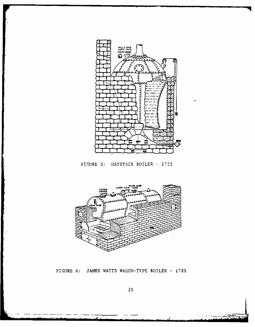
The Watt wagon-type boiler, Fig. 6, and the
cylindrical or flueless boiler, Fig. 7, are made up of flat
plates rolled to shape and riveted or welded longitudinally
and also circumferentially when several plate lengths are
required to obtain the desired capacity provided with a
24
__L
SAH'ITy VALVE
FIGURE 5: HAYSTACK BOILER - 1725
SFET YAL OOS _
FIGURE 6: JAMES WATTS WAGON-TYPE BOILER - 1785
25
water-inlet, a condensate return, a steam outlet, a gauge
glass for ascertaining the water level, and a safety valve
for the relief of excess pressure makes the simplest kind of
boiler when mounted over a suitable refractory combustion
box or chamber and entirely insulated against heat loss.
This elementary design is rather awkward and requires much
space since the tank or drum is limited in its pressure with-
standing capabilities. The use of this type of boiler is
restricted to a moderate working pressure and stationary
applications only.
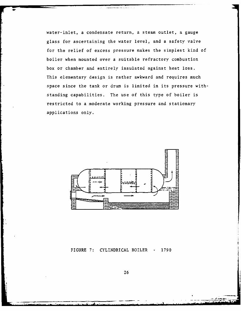
FIGURE 7: CYLINDRICAL BOILER - 1790
26

Cylindrical boilers function by burning fuel in
a refractory combustion chamber constructed under the cylin-
drical drum. The combustion products flow along the underside
of the drum from front to back and then exit through an uptake
to the chimney or stack. The heat in the flue gases must be
transmitted through the metal drum into the liquid in order
to preheat and vaporize it. Since the time element is short,
with the gases passing from front to back only once, then
exiting, the overall efficiency of this arrangement is low.
The boiler is a notorious slow steamer; however, once the
steaming action has started, it is a steady steamer. These
boilers are limited to 'small capacities, usually to 350 boiler
horsepower, because of their inherent tendency to explode.
FIGURE 8: OLIVER EVAN'S RETURN-FLUE BOILER - 1800
27
.. . . .
- *T
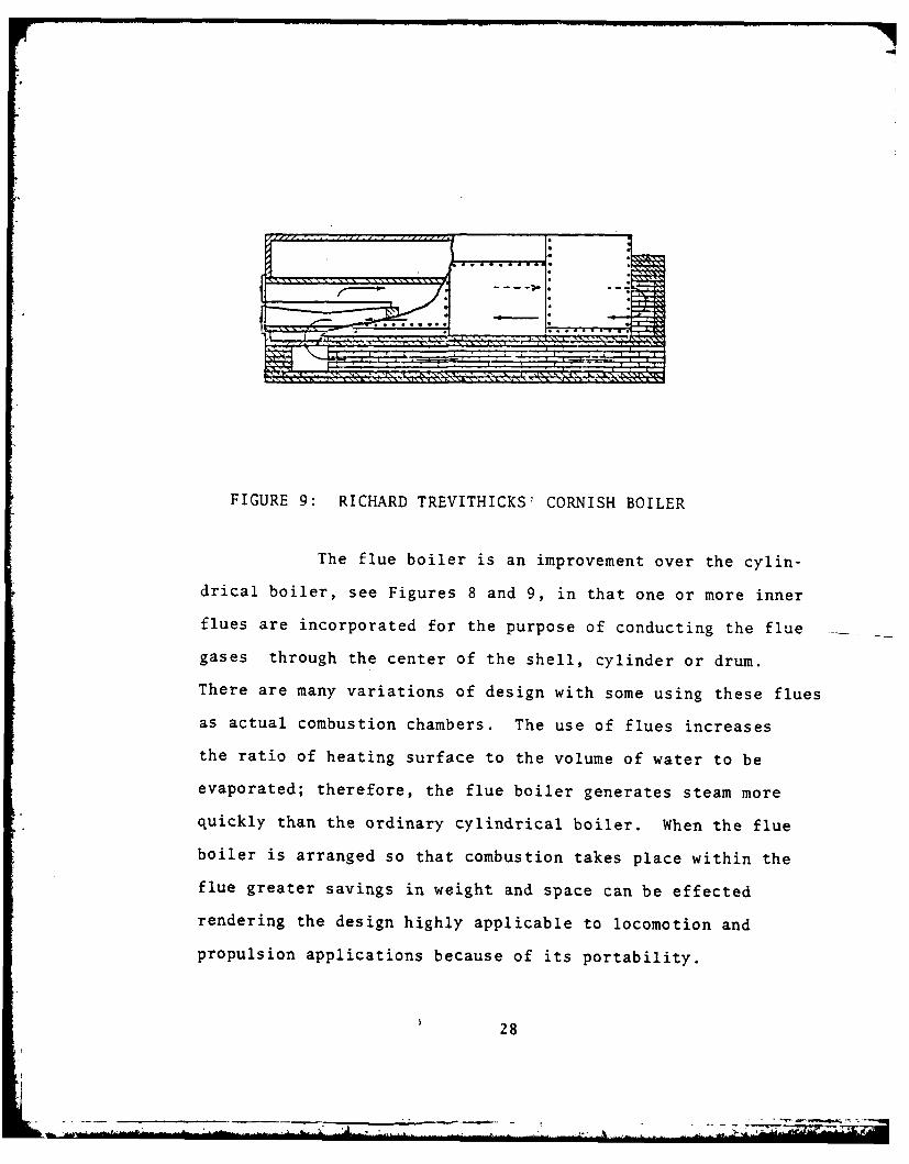
FIGURE 9: RICHARD TREVITHICKS CORNISH BOILER
The flue boiler is an improvement over the cylin-
drical boiler, see Figures 8 and 9, in that one or more inner
flues are incorporated for the purpose of conducting the flue
gases through the center of the shell, cylinder or drum.
There are many variations of design with some using these flues
as actual combustion chambers. The use of flues increases
the ratio of heating surface to the volume of water to be
evaporated; therefore, the flue boiler generates steam more
quickly than the ordinary cylindrical boiler. When the flue
boiler is arranged so that combustion takes place within the
flue greater savings in weight and space can be effected
rendering the design highly applicable to locomotion and
propulsion applications because of its portability.
28
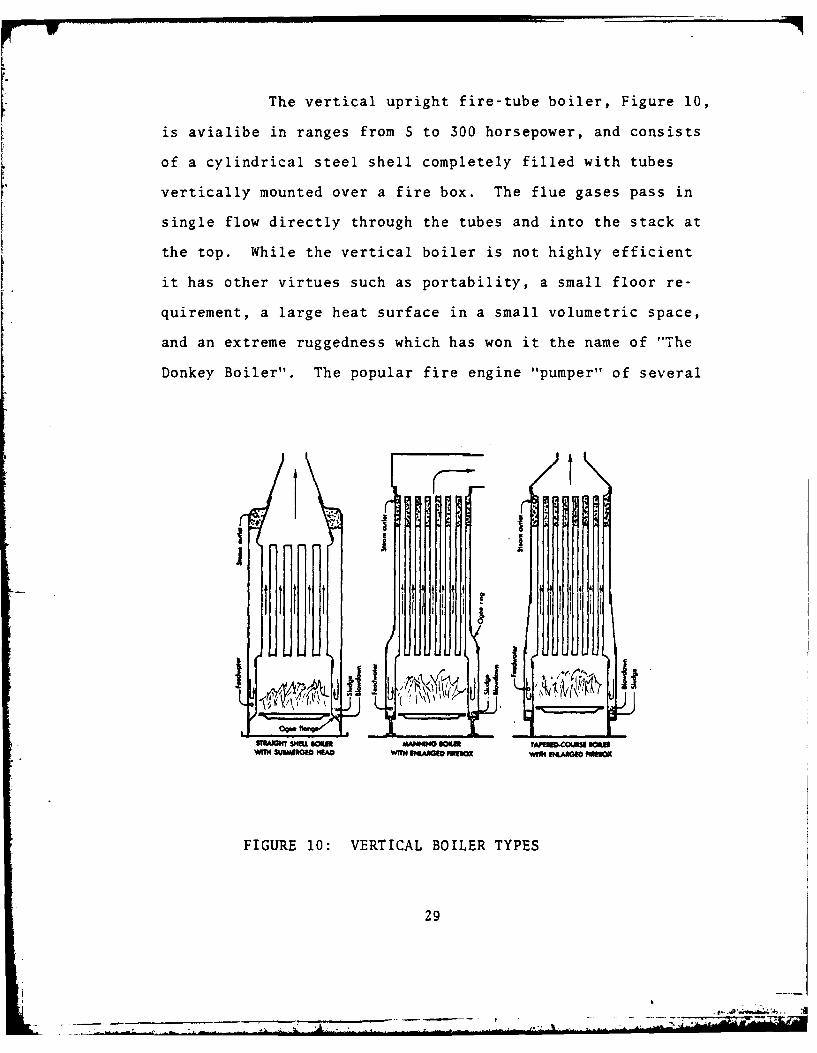
The vertical upright fire-tube boiler, Figure 10,
is avialibe in ranges from S to 300 horsepower, and consists
of a cylindrical steel shell completely filled with tubes
vertically mounted over a fire box. The flue gases pass in
single flow directly through the tubes and into the stack at
the top. While the vertical boiler is not highly efficient
it has other virtues such as portability, a small floor re-
quirement, a large heat surface in a small volumetric space,
and an extreme ruggedness which has won it the name of "The
Donkey Boiler". The popular fire engine "pumper" of several
I I
! ] I
1N41
- -
WRM 3U QR A Wff N DASO FM930Z WfH B4A*0 FOX=
FIGURE 10: VERTICAL BOILER TYPES
29

decades ago used this type of boiler to generate high pressure
steam in order to motivate a reciprocating piston plunger
pump. It also found wide use in the inaccessible, mountainous
terrain of the Pacific Northwest during the logging boom of
the late 1880's.
Fire-tube boilers become limited as capacity and
pressure requirements increase. Larger shell diameters re-
quire thicker plates to withstand the temperature and pres-
sure stresses. Temperature differentials in the boiler create
high stresses. These stresses combined with the effects of
precipitates and other deposits have caused many boiler
explosions (Ref. 2]. Other disadvantages include long warm-up
time requiring up to 15 hours to produce steam for propulsion,
unequal expansion of metal parts at an increased firing rate,
faster expanding fire tubes tend to pull loose from the boiler
shell, heavy weight, up to 15 lbs of boiler and water to pro-
duce 1 lb of saturated steam per hour and inefficiency
requiring large amounts of fuel to produce a relatively small
amount of steam.
Fire-tube boilers tend to be dangerous at high
steam pressures. This is partly due to inherent structural
problems and partly due to the relatively large quantity of
water and steam contained in the boiler. In the event of a
rupture in the boiler, the large amount of water and steam
releases great destructive energy. With this ever-increasing
demand for more and more steam at higher and higher pressure
30
. . . .. . , . . . . . , i, ,< I
the water-tube boiler was developed. When steam and water
at elevated pressure are confined within a tube of small or
moderate diameter the thickness requirement is reasonable and
practical.
b. Water-Tube Boilers
The water-tube boiler is composed of drums and
tubes which are external to the drums and serve as intercon-
nections for them. The drums store water and steam and con-
tain no tubular heating surface, thereby allowing for these
vessels to be much smaller in diameter than a fire-tube
boiler shell and resulting in resisting higher pressures.
This boiler may be a straight or bent-tube type, and in both
cases, the tubes possess the entire heating surface.
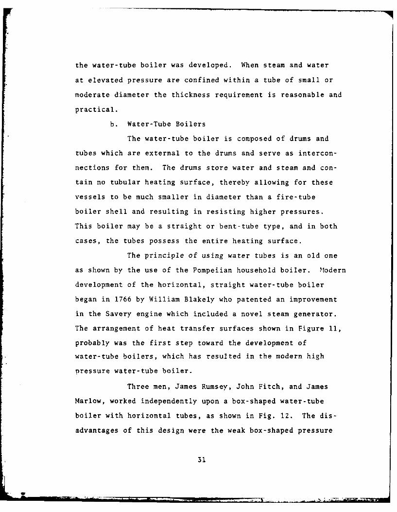
The principle of using water tubes is an old one
as shown by the use of the Pompeiian household boiler. Modern
development of the horizontal, straight water-tube boiler
began in 1766 by William Blakely who patented an improvement
in the Savery engine which included a novel steam generator.
The arrangement of heat transfer surfaces shown in Figure 11,
probably was the first step toward the development of
water-tube boilers, which has resulted in the modern high
pressure water-tube boiler.
Three men, James Rumsey, John Fitch, and James
Marlow, worked independently upon a box-shaped water-tube
boiler with horizontal tubes, as shown in Fig. 12. The dis-
advantages of this design were the weak box-shaped pressure
31
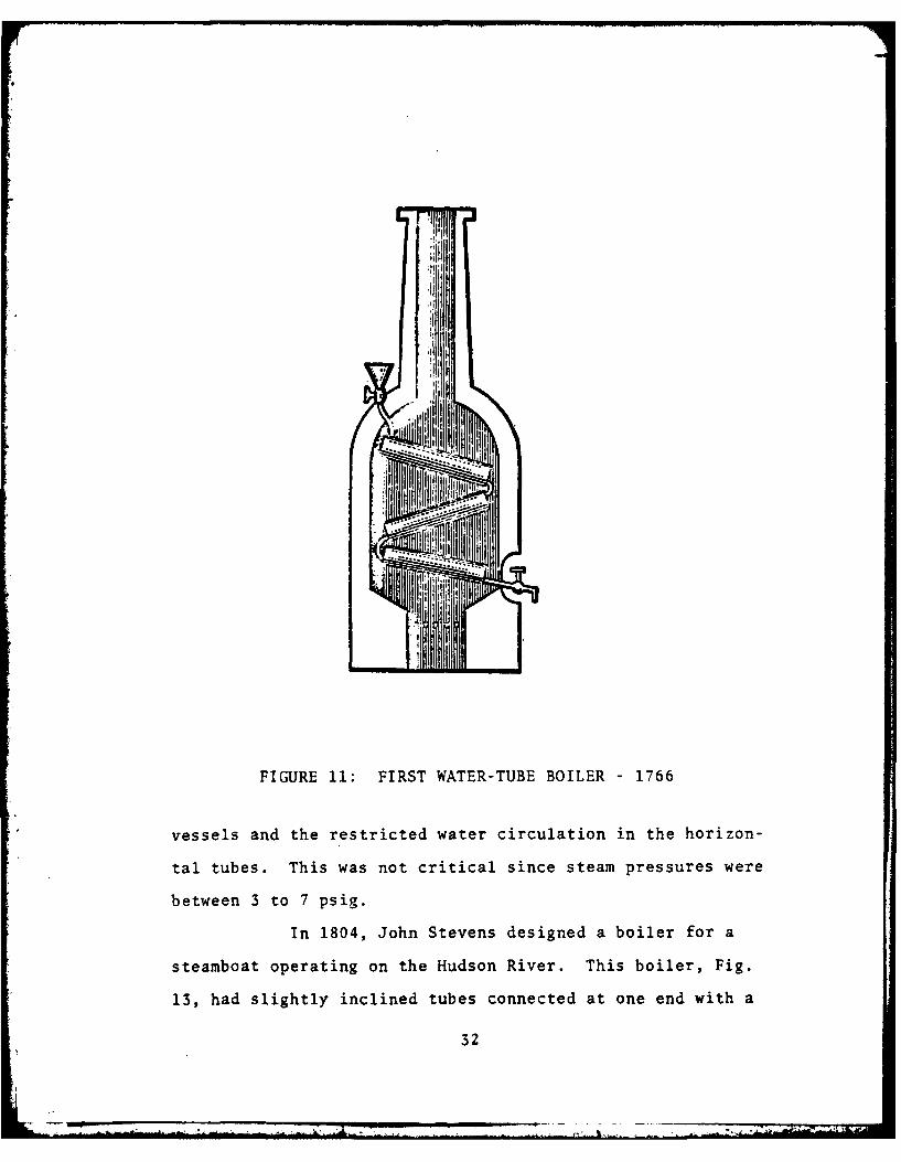
FIGURE 11: FIRST WATER-TUBE BOILER 1766
vessels and the restricted water circulation in the horizon-
tal tubes. This was not critical since steam pressures were
between 3 to 7 psig.
In 1804, John Stevens designed a boiler for a
steamboat operating on the Hudson River. This boiler, Fig.
13, had slightly inclined tubes connected at one end with a
32

reservoir. The Steven's Porcupine boiler, as it is known,
marked a definite advance in design of high pressure steam-
generating apparatus, as its working pressure was 50 psig.
Again, lack of proper water circulation in the tubes was a
________ * ooooooooI_________ -ooooooooo0(
_________ 000000000000oI_________ -000000000000I.
- ooooooo0Cooo________ - oooooooooo
_________ - o000ooo0oo1_________ 00oo1o00oo000I__________ -ooo0oo0oo 11__________ - oooooooo0oo
FIGURE 12 BOX-SHAP WATER-TUE BOILER-19
FIGURE 13: JOX-HNATEENS'APRCTUPIE BOILER -1804

serious defect. Stevens' son, John Cox Stevens, designed a
water-tube boiler in 1805. This boiler, shown in Fig. 14,
consisted of 20 vertical tubes arranged in a circle, connecting
a water space at the bottom and a steam space at the top.
The steam and water chambers were annular spaces of small
cross section and small volume.
4i
FIGURE 14: JOHN COX STEVENS' WATER-TUBE BOILER 1805
Figures 15, 16, 1' and 18 show the development of
the water-tube boiler in the next sixty years. The first
sectional water-tube boiler with well defined circulation was
built by Joseph Eve in 1825. Sectional boilers have the
34
R4
FIGURE 15: THE FIRST SECTIONAL WATER-TUBE BOILER - JOSEPHEVE - 1825
water-steam spaces divided into small sections, none of which
is subject to disastrous explosion. Basically all water-tube
boilers are sectional in character. Figure 15 shows the
sectional composed of small tubes, practically vertical but
with a slight double curve. The tubes were fixed in larger
horizontal tubes called headers, which, in turn, were connected
to a steam space above and a water space below. The steam and
water spaces were joined by outside pipes (down-comers) to
35
...... . t

secure a circulation of water up through the sections and down
through the external pipes. In 1826, Goldworthy Gurney built
a number of boilers for use on his steam carriages, one of
which is shown below. This boiler consisted of a number of
FIGURE 16: GOLDWORTHY GURNEY'S CARRIAGE BOILER - 1826
small "U" tubes, laid sidewise, with the ends connected to
larger horizontal pipes. These, in turn, were connected by
vertical pipes to permit circulation and also were connected
to vertical cylinders serving as steam and water reservoirs.
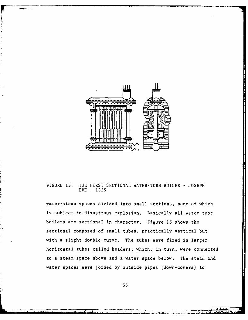
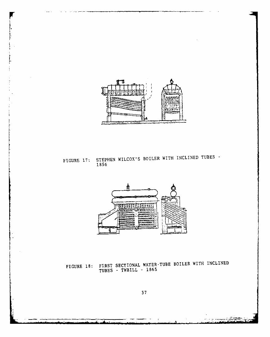
In 1856, Stephen Wilcox first used inclined water-tubes to
connect water spaces at the front and rear with a steam space
above, Fig. 17. The first to use inclined tubes in a sectional
form was George Twbill in 1865, Fig. 18. He used wrought iron
36
r
FIGURE 17'. STEPHEN WILCOX'S BOILER WITH INCLINED TUBES -
FIGURE 18: FIRST SECTIONAL WATER-TUBE BOILER WITH INCLINED
TUBES - TWILL - 1865
37

tubes connected at the front and rear to standpipes. These
standpipes carried the steam to horizontal cross-drums at the
top, the entrained water being separated and led to the rear
standpipe. In the following years, development of water-tube
boilers continued with great vigor. Steam drums soon were
substituted for the nest of cast iron tubes and pipes origi-
nally used for steam and water storage. Steel replaced cast
iron for the generating tubes. Large tubes were replaced by
small tubes to increase heat transfer areas. The transition
to water-tube boiler design didn't arrive until the end of the
19th century when the triple expansion reciprocating steam
engine was introduced to the navies of the world.
The head type boiler was the first form of water-
tube boiler to displace the fire-tube type for use in steam
vessels. A header type boiler was installed in the yacht
Reverie in 1889 with a designed pressure of 225 psig. The
success of this and other similar installations led to a
decision by the Admiralty to use this boiler in the British
Navy. In 1896, the U. S. Navy installed this type in three
vessels, Marietta, Annapolis, and Chicago.
Although the Reverie design was an outstanding
success and proved to be far more satisfactory in service than
other boilers previously used by the Navy, combustion was not
entirely satisfactory. The shape of the furnace made it
necessary to slope the grates down toward the rear to gain
furnace volume. At high ratings, this furnace was not suitable
38
for good combustion. Also, the fittings and water gages were
not readily accessible from the firing aisle because of the
steam drum location.
To overcome these difficulties, the design was
modified to permit firing from the opposite end. Combustion
conditions improved since the furnace was enlarged in the
direction in which combustion took place. The grates were
relocated and the accessibility of the tubes for cleaning from
the fireroom floor was improved greatly. The steam drum was
now at the firing end of the boiler, where the water gage could
be seen easily and all fittings were more accessible. These
modifications, seemingly very simple, revolutionized marine
water-tube boiler design. The many improvements throughout
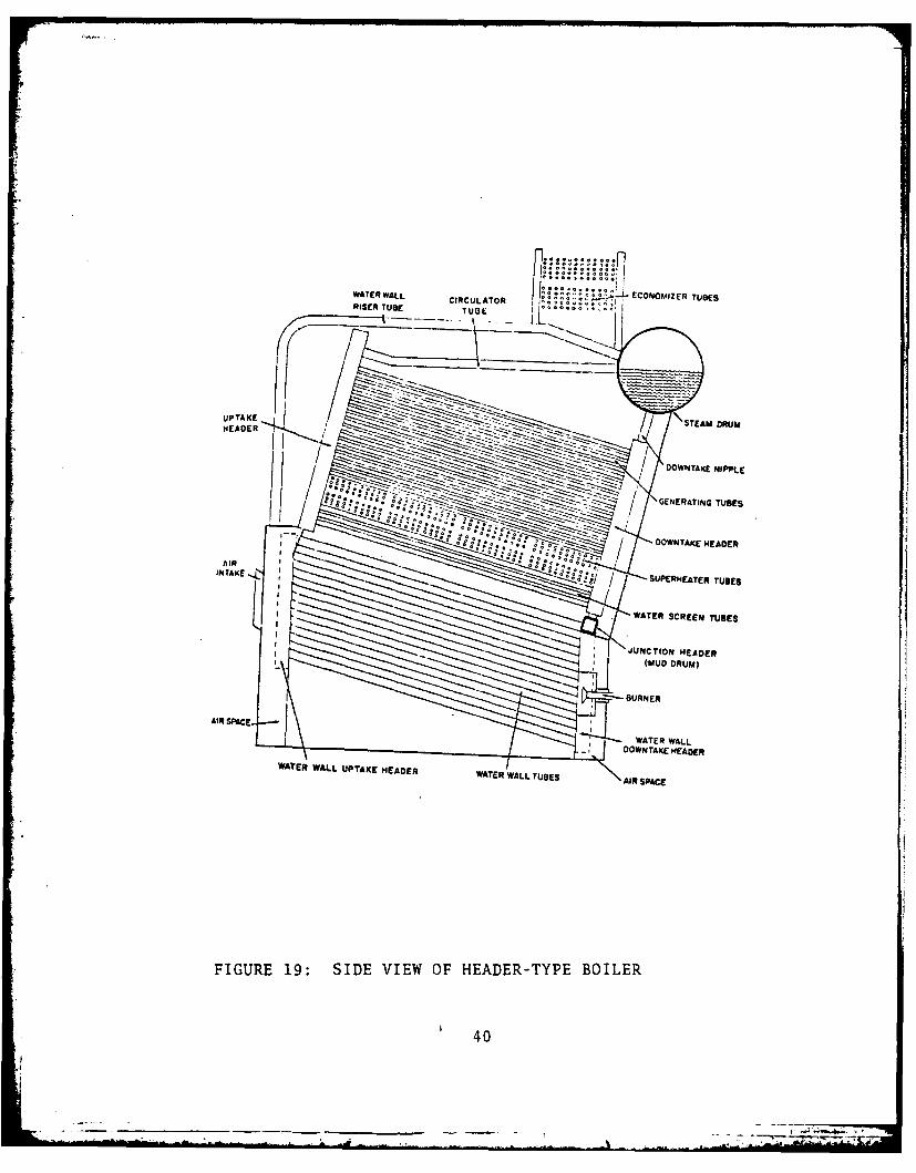
the years have resulted in the sectional header type boiler,
shown in Fig. 19, as we know it today.
The necessity for more steam brought on experi-
mentation with forced draft to accelerate combustion of marine
boilers. Although Robert Stevens tried in 1827 to supply air
by forced draft, it was not until 1880 before a successful
forced draft system was designed by James Howden. Interest-
ingly, his design also included means by which waste heat in
flue gases was used to heat the incoming air for combustion.
The increased steam pressures and rapidity of steam generation
led to serious trouble arising from overheating of tube ends
and tube-sheets, causing many breakdowns and explosions from
endeavors to work cylindrical fire-tube boilers under forced
39
-- - - - -- - - - - - - - --i- - - - ~" .. .... ' .. .. ... .... .. . II : " - ' -
WATER WALL CCUAO .......... ECONOMIZER TUBESRISER TUBE TU....
UPAE STEAM DRUM
~ / OOWP4TAKE 141PPLEI ~ / GENERATING TUBES
* * OOWNTAKE HEADER
AIRINTAE.~0:0./ / SUPERHEATER TUBES
WATER SCREEN TUBES
JNCTION HEADER
AIR SPACE
- OWN TAKE HEADER
WATER WALL UPTAKE HEADER WTRWLTBSARPC
FIGURE 19: SIDE VIEW OF HEADER-TYPE BOILER
40
draft. The proponents of this boiler type, satisfied with
the partial solution of installing tube inserts in the tube
ends, argued that the generated pressures were sufficient for
their needs.
Then in 1894, Charles A. Parsons developed and
proved the superiority of the steam turbine for marine propul-
sion. The advantages of the turbine were immediately apparent
and within a relatively short time (1894-1914) almost all
important ships of the world navies were driven by turbines.
Higher pressures, greater steam capacity and utilization of
propulsion turbines concurrently accelerated the development
of the water-tube boiler. A major contribution to higher
pressure and greater steam capacity was the evolution of
treating boiler water to prevent scale formation and boiler
corrosion.
From the days of the caldron boiler until well
into the turn of the 20th century there was very little im-
provement in steam generation except in the larger power-
generating stations operated by the greater public utilities.
At the end of the 19th century the new fast torpedo boats and
destroyers, demanding boilers of light and compact design,
brought forth the drum-type express boiler. The name "express"
is used in its sense "dispatched with special speed" and is
applied to this type boiler because of the "speed" with which
steam can be raised and with which this boiler can answer
steam demand changes.
41
- - - l'.r,

UPTAKCES
t _STEAM DRUMA
DOWNCOMERSGENERATINGAND CIRCU-
LATING TUBE BANK_/ , \_ FURNACE WAE DR oUMWTER DRUM
FIGURE 20: BASIC "A" TYPE BOILER
The development of drum-type boilers as applicable
to naval vessels to present time is shown in Figs. 20-29.
Figure 20 illustrates the basic design of A-type boilers (so
named because of the shape of the generating elements resem-
bling the letter "A") which evolved from such early designs as
the Yarrow express boiler shown in Fig. 21. The A-type boiler
was originally designed as a coal-fired boiler (converted from
coal to oil during the decade between 1905-1915) and was widely
used for many years with only minor changes and additions.
42

FIGURE 21: YARROW TYPE BOILER
/ PTAM
PROTECTION STEAM CCU'
IA1U DINM
FIGURE 22: "All TYPE BOILER WITH UNCONTROLLED INTERGRALSUPERHEAT
43

HEAI CIRCUIATDNI PIPES
REAR
~** SUFEMOETER
VERTI
SUPWIEATERBUNR DM
WATER SCREEN OEIG
FIGURE 23: SECTIONAL EXPRESS TYPE BOILER -1939
,/000 0 ol IN
00nmM aa 10
m. 0 a a
ma f
WL PN A LL OV41* 0 A~SP I* IWA1U T IV.PAM " M W ALYW
FIGUREHWM 24: SEPARATEL FIE UERETRBILR 13
44rm yuI"v

World War II created a huge demand for powerful,
packaged, compact steam generators simple to operate and easy
to maintain for use by the armed forces ashore and afloat.
Under this stimulus, designs were developed that are capable
of delivering two to three times the output of earlier boilers
containing the same heating surface. In some cases this can
be accomplished in one-quarter the previous volumetric space
requirement at great savings in weight and with efficiencies
running on the average of 80% [Ref. 3]. This was extremely
important to offset the increasingly congested space conditions
aboard destroyers.
...... .. O 0
TUBE GAS-TIGHT
SLIPrM0lEATED
SUPEREAT STEAMS SA T SID ETEMPERATURECONTROL FURNACE S PRESSURE
DIVISION WALL HEAOER FEOEM SION WAL HEADER CONTROL FUM E
FIGURE 25: "A" TYPE BOILER FOR GENERATING SUPERHEATED STEAMWITH CONTROLLED, INTEGRAL, INTERDECK SUPERHEAT
4S
* - ... ... .......- ,-.--------....----,., -
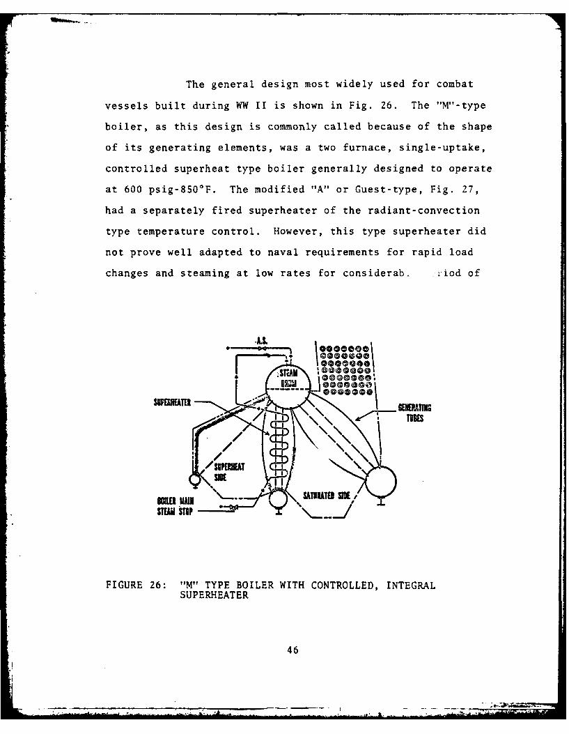
The general design most widely used for combat
vessels built during WW II is shown in Fig. 26. The "M"-type
boiler, as this design is commonly called because of the shape
of its generating elements, was a two furnace, single-uptake,
controlled superheat type boiler generally designed to operate
at 600 psig-8500 F. The modified "A" or Guest-type, Fig. 27,
had a separately fired superheater of the radiant-convection
type temperature control. However, this type superheater did
not prove well adapted to naval requirements for rapid load
changes and steaming at low rates for considerab,. :riod of
@000000
/ v/
um %\.! SATUATO SEIX/
FIGURE 26: "M" TYPE BOILER WITH CONTROLLED, INTEGRALSUPERHEATER
46

\oooo0\ man
. - ..... 0000%'
31ATSItEATE31Ult WAR
0 00
FIGURE 27: MODIFIED. "A ORGETBIE
il Ku a
t " W IE / "E -- -
FIGURE 27: MODIFIED "All OR GUEST BOTLER
time. Another boiler used mainly in WW II destroyer escorts
is the single furnace boiler shown in Fig. 28. The "D" boiler
is the progenitor of boilers used in post-World War II ship
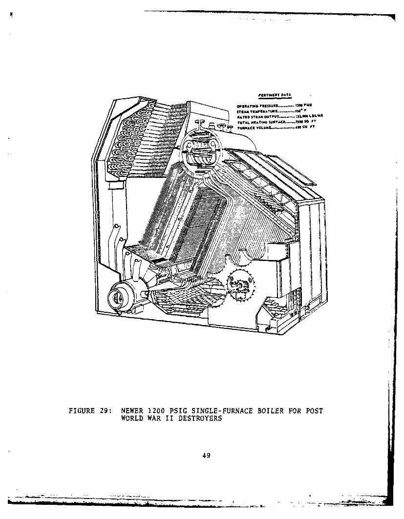
construction. Figure 29 shows the 1200 psig boiler which has
become the major naval fossil-fired steam generator.
47
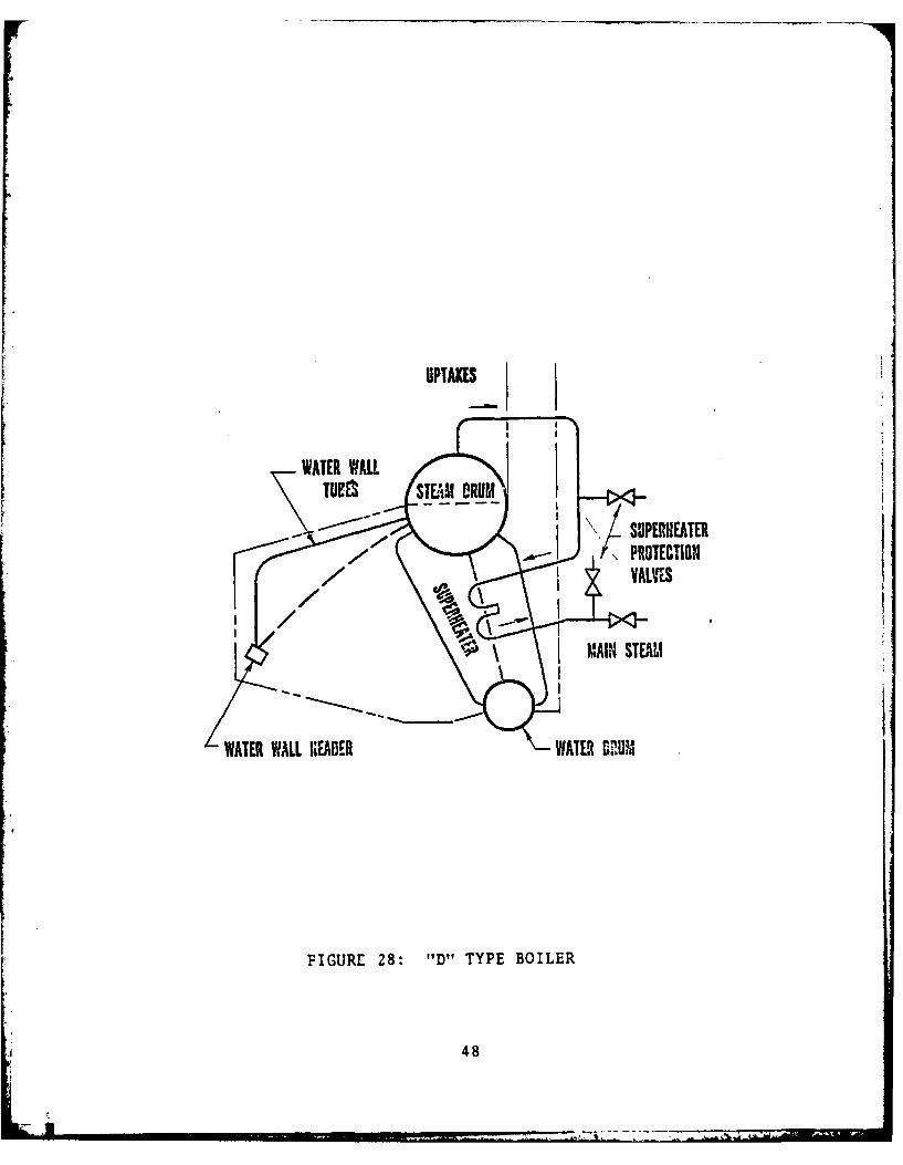
UPTAKES
TEI STAV DRUM
\S'JPERNEATER
T\PROTECTION
'*'MAIN STEAM
WATER WALL HIEADER WATER 611M?
FIGURE 28: I'D" TYPE BOILER
48
PERTMSgM? DATA
FIUR 2: EWR 20 PIGSIGL-F RAE BOI$UL ...OR 2 PSTWORLD WARA OUPU~~ DESTROYERSMl
To49TNG$*AL _.$ 0P
-~~~UMC V__________________ 4nCU P

4. Water Circulation
The majority of the previously discussed boilers have
depended upon natural convection for the water-side circula-
tion. That is, the difference in density between the water
near the combustion chamber being heated and the cooler water
in more remote parts of the boiler causes a natural flow away
from the combustion chamber which in many cases is adequate.
As boiler pressure increases, however, there is less difference
between the densities of water and steam. At pressures over
1000 psig the density of steam differs so little from the
density of water that natural circulation is harder to achieve
than it is at lower pressures [Ref. 61 . At high pressures
positive circulation boilers have a distinct advantage because
their circulation is controlled by pumps and is independent of
differences in density. The utilization of pumps to circulate
and agitate boiler water increases heat transference, thereby
increasing the output of a boiler without increasing the heat-
ing surface.
There are two main kinds of positive circulation
boilers; one type is known as a controlled circulation or
forced recirculation boiler and the other is known as a once-
through or forced-flow boiler. In both types of boilers
external pumps are used to force the water through the boiler
circuits; the essential difference between the two lies in
the amount of water supplied to the boiler.
so
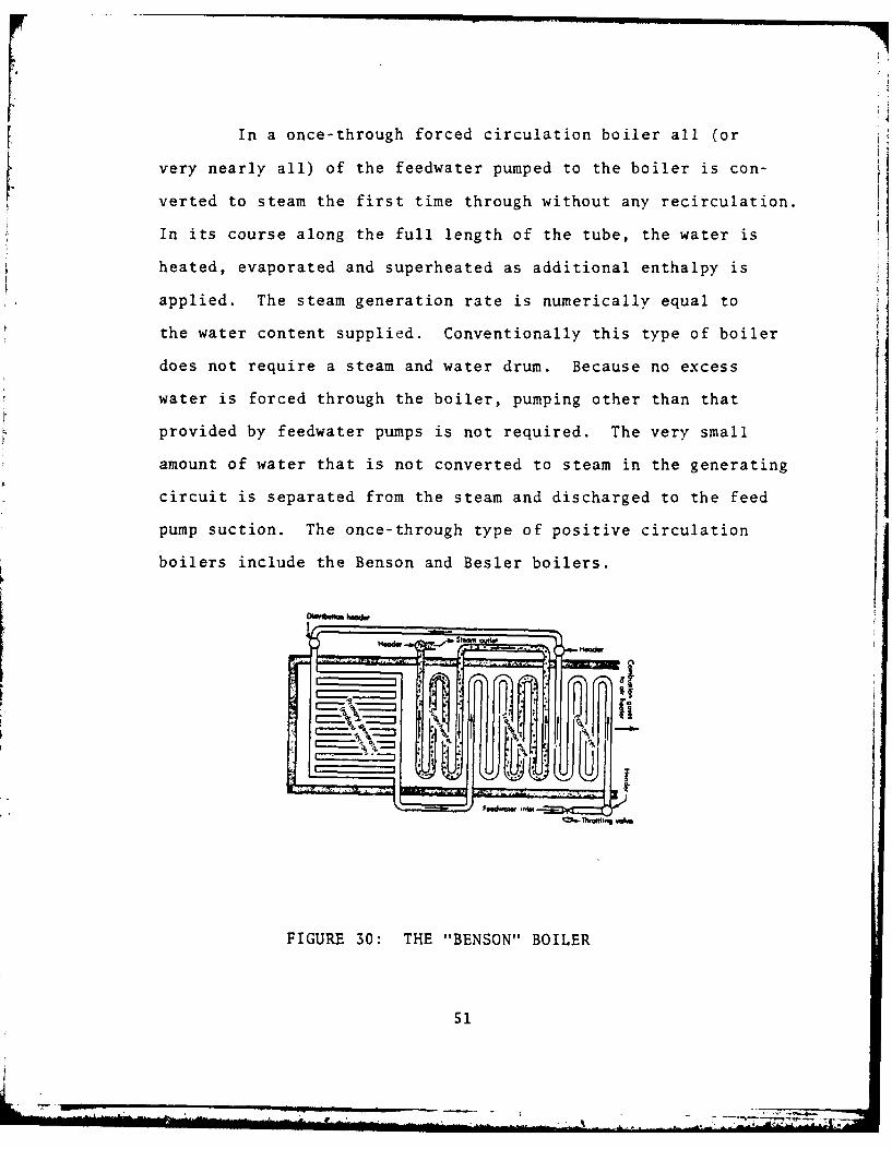
In a once-through forced circulation boiler all (or
very nearly all) of the feedwater pumped to the boiler is con-
verted to steam the first time through without any recirculation.
In its course along the full length of the tube, the water is
heated, evaporated and superheated as additional enthalpy is
applied. The steam generation rate is numerically equal to
the water content supplied. Conventionally this type of boiler
does not require a steam and water drum. Because no excess
water is forced through the boiler, pumping other than that
provided by feedwater pumps is not required. The very small
amount of water that is not converted to steam in the generating
circuit is separated from the steam and discharged to the feed
pump suction. The once-through type of positive circulation
boilers include the Benson and Besler boilers.
FIGURE 30: THE "BENSON" BOILER
51

The Benson Boiler, Fig. 30, is characterized by the
complete absence of steam separating drums. The unit responds
sensitively to combustion rate changes and is therefore well
adapted for use with a special turbine design in which variable
pressure is used tc accomodate a variable load. This boiler
was first built in England (1923) by Mark Benson, a Czechos-
lovakian, but was developed by Siemens, Inc., in Germany. It
has been built with capacities as large as 220,000 ibm/hr at
3200 psig.
Figure 31 shows the boiler circuit of a controlled
circulation (or forced recirculation) boiler. In this boiler
the water in the tubes is not evaporated to complete dryness
but only to the point at which dissolved salts and solids are
retained in solution. The mixture of water and steam passes
to the steam-and-water drum where the steam is separated. The
steam is passed through a separator where excess water is re-
moved, then passed to a superheater. The separated water,
along with feedwater, is returned to (or recirculated through)
the heating circuit through the downcomers. The quantity of
water passing through the boiler (circulation rate) is from
3 to 20 times the amount evaporated. This ratio requires
constant speed recirculating pumps in addition ta the boiler
feedwater pumps.
5. Heat Source
The heat may be derived from (1) the combustion of
fuel (solid, liquid, or gaseous); (2) the hot waste gases of
52

P
_ [JKZ Z
53
other chemical reactions; (3) the application of electrical
energy; or (4) the utilization of nuclear energy.
Items 1, 3, and 4 are the most prevelant methods of
supplying a heat source, but the increasing need for energy
conservation has necessitated increased utilization of waste
heat recovery. Wherever a process waste product or gas is
continuously discharged at a temperature of 1,000'F or higher,
heat recovery should be considered. In addition to producing
useful steam, the lowering of the flue gas temperature reduces
maintenance of flues, fans, and stacks. One proposal for
"by-product heat recovery" utilizes the hot exhaust gases from
a shipboard gas-turbine propulsion plant as the heat source
for a conventional Rankine cycle. This provides the means by
which useful work can be extracted from a once wasted energy
source.
B. RACER AND THE SST
The realization of finite petroleum resources has prompted
researchers to accelerate the development of alternative fuels
and energy sources, the employment energy conservation methods
for short term relief, and the investigation of long term con-
servation techniques. The Navy, having made a major commitment
to gas turbine propulsion systems, is currently investigating
a means of fuel conservation without a reduction in steaming
1Waste heat is a misnomer; a more appropriate term is "by-pro-duct heat."
54

time. The RAnkine Cycle Energy Recovery (RACER) system is being
developed to recover some of the heat contained in the gas tur-
bine exhaust gases.
The DD-963, FF6-7, and the DDG-47 class of ships are powered
by the General Electric LM 2500 Marine gas turbine engine. The
RACER system, an unfired waste heat recovery system, will func-
tion as a bottoming cycle for the LM 2500. Program requirements
specify the development of a high efficiency cruise engine that
utilizes hot exhaust gases to heat the working fluid (water)
and convert it to useful energy through a steam turbine. It
is intended that the design be compatible with the basic LM
2500 Marine gas turbine providing one shafts worth of power to
the DD-963 and FFG-7, U.S. Navy surface cambatants. Further,
specifications require provisions that will permit satisfactory
inspection and cleaning of watersides/steamsides. It is im-
portant that internal surfaces can be properly observed for
corrosion, scaling, defects, repairs, etc. Cleaning methods
and techniques should be simple, easy to use, and practical for
use with the proposed design.
The boiler, placed in the exhaust ducting, would by necessity
have to be compact and lightweight, have a high steam generation
rate and excellent response characteristics as well as simplicity
in design, installation, and maintenance. LCDR Combs [Ref. 71,
in his thesis conducted a feasibility study for propulsion
assistance on waste heat recovery as applied to the Spruance
class destroyers. Results of the study indicate that this
55
* -- ---- --- -.-- ---- - t

proposal provides for substantial fuel savings based upon
operational considerations. The proposed Rankine cycle in-
cluded a once-through (O.T.) boiler having an optimal operating
pressure of 600-800 psig.
For this application, the O.T. boiler is particularly
attractive due to its small size. A special class of once-
through boilers, which provides a possible design alternative,
is the Short Straight Tube (S.S.T.) boiler. Also known as
the "stagnation" (non-flow) boiler, it has excellent perfor-
mance as a steam generation unit. This boiler has the same
components as the O.T. boiler; however, in contrast, its
construction consists of short (1-2 meters) and straight tubes
with toroidal headers, Fig. 32. Due to boiler water level
control and water chemistry problems, the S.S.T. boiler all
but disappeared since the early 1900's. With the advancements
made in water chemistry procedures and with the development
of automatic boiler control systems, these problems should be
alleviated, allowing present day application.
When compared to the normal forced or natural convection
boilers, the once-through boiler is more desirable for waste
heat recovery on the Spruance class destroyer. The O.T.
boiler is lighter and safer, since no steam drum is required
and the total mass of water is substantially less. However,
a reveiw of its construction reveals, Fig. 33, a complicated
arrangement of headers and long "serpentine" tubes. This
leads one to question its applicability, especially in terms
56

STE.'AM OUT
TOPHEADER
TUBES
I
BOTTOM LHEADER
f JWATER IN
FIGURE 32: SHORT STRAIGHT-TUBE BOILER UNIT
S7

of simplicity. In contrast, the S.S.T. boiler has a charac-
teristic which makes it very attractive for this purpose. As
it is the simplest of boiler designs, it lends itself to lower
fabrication cost and simplified maintenance.
C. OBJECTIVE
The S.S.T. boiler is undergoing a resurgence in Japan for
industrial usage due to its performance and construction
(Ref. 81. These industrial applications are for steam supplied
up to 150 psig. In order to employ such a design at higher
pressures, it is necessary to obtain some essential information.
In general, this need for information arises from three
sources. First, the designerreauires detailed information in
order to provide for an optimal design. This entails a de-
tailed quantitative study, for example, of heat transfer co-
efficients and two phase pressure drop. Secondly, operational
conditions must be evaluated to ascertain the optimal steady
state and transient operating conditions. Inclusive is
casualty control data to diagnose faults due to the departure
from the optimal conditions. Finally, and most paramount, is
the requirement for the precise maximum safe operational limit.
For these reasons, experimental investigation to ascertain
design, operation and safety criteria is necessary. Firm
establishment of the characteristics unique to the Short-Straight
Tube Boiler is required to provide the means by which performance
evaluation and comparison with other evaporators can be made.
However, a lack of design and operational experience doesn't
58
allow the engineer to anticipate S.S.T. characteristics a
priori. Therefore, the logical beginning to experimentation
is having a model from which predictions can be made.
The objective of this thesis therefore, is the development
of a suitable model and computer program to provide the means
for analytic study of the S.S.T. principle.
59
II. MODEL DESCRIPTION
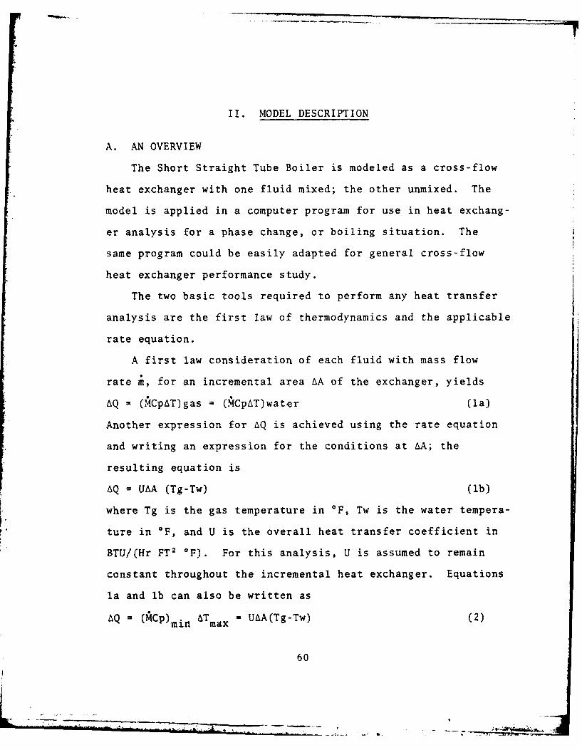
A. AN OVERVIEW
The Short Straight Tube Boiler is modeled as a cross-flow
heat exchanger with one fluid mixed; the other unmixed. The
model is applied in a computer program for use in heat exchang-
er analysis for a phase change, or boiling situation. The
same program could be easily adapted for general cross-flow
heat exchanger performance study.
The two basic tools required to perform any heat transfer
analysis are the first law of thermodynamics and the applicable
rate equation.
A first law consideration of each fluid with mass flow
rate i, for an incremental area AA of the exchanger, yields
AQ = (MCpAT)gas = (MCpAT)water (la)
Another expression for AQ is achieved using the rate equation
and writing an expression for the conditions at AA; the
resulting equation is
AQ = UAA (Tg-Tw) (lb)
where Tg is the gas temperature in OF, Tw is the water tempera-
ture in oF, and U is the overall heat transfer coefficient in
BTU/(Hr FT 2 OF). For this analysis, U is assumed to remain
constant throughout the incremental heat exchanger. Equations
la and lb can also be written as
AQ = (ACP) min ATmax - UAA(Tg-Tw) (2)
60
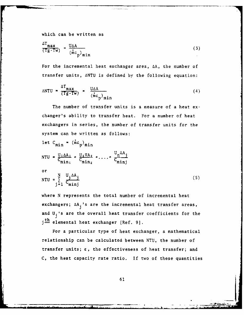
which can be written as
ATmax UAA
(Tg-T = - (c~m (3)(;Cp )min
For the incremental heat exchanger area, AA, the number of
transfer units, ANTU is defined by the following equation:
NTU - AT max UAA (4)T g- Tw) (mc p)min
The number of transfer units is a measure of a heat ex-
changer's ability to transfer heat. For a number of heat
exchangers in series, the number of transfer units for the
system can be written as follows:
let Cmin = (;cp)min
NTU -UiAAi + U2VAz .. U n A j
Cmin, C min2 .. C minj
or N U. AAU (NTU = U , U5)j = Cminj
where N represents the total number of incremental heat
exchangers; AAj's are the incremental heat transfer areas,
and U.'s are the overall heat transfer coefficients for theh
jth elemental heat exchanger [Ref. 9].
For a particular type of heat exchanger, a mathematical
relationship can be calculated between NTU, the number of
transfer units; e, the effectiveness of heat transfer; and
C, the heat capacity rate ratio. If two of these quantities
61
-j -A.- 4-.

are known, this mathematical relationship can be used to cal-
culate the unknown. Reference [10] lists this relationship
for cross-flow as follows:
C min N=NTU UACmax min
Cmax mixed, Cmin unmixed
= (1/C) I-EXP i-C(1-e'N) (6a)
Cmax unmixed, Cmin mixed
= -EXP [I(1/C 11-EXP(-NC)(J (6b)
If the hotter fluid is a condensing vapor or the cooler fluid
is a boiling liquid, the heat capacity ratio C = 0. For this
case, Kays and London [Ref. 11] show that equation 6 reduce
to
e = I-EXP(-NTU) (7)
The proposed model utilizes this procedure to determine the
overall heat transfer coefficient for the straight-vertical-
tube cross-flow heat exchanger used as a boiler.
In the development of the model, the following assumptions
were made:
1) A tube could be modeled as a group of N heat exchangers
connected in series. The value of N is determined from fin
geometry as the product of tube length times the number of
fins per inch.
62
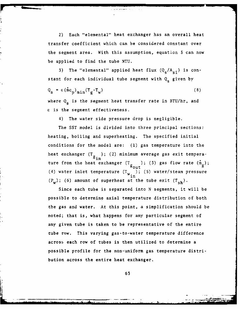
2) Each "elemental" heat exchanger has an overall heat
transfer coefficient which can be considered constant over
the segment area. With this assumption, equation 5 can now
be applied to find the tube NTU.
3) The "elemental" applied heat flux (Q s/A si) is con-
stant for each individual tube segment with Qs given byQs = E(;c p) min (T -T W) (8)
where Qs is the segment heat transfer rate in BTU/hr, and
e is the segment effectiveness.
4) The water side pressure drop is negligible.
The SST model is divided into three principal sections:
heating, boiling and superheating. The specified initial
conditions for the model are: (1) gas temperature into the
heat exchanger (T gin); (2) minimum average gas exit tempera-
ture from the heat exchanger (T ); (3) gas flow rate ( g);goug
(4) water inlet temperature (T w); (5) water/steam pressurein
(Pw); (6) amount of superheat at the tube exit (Tsh).
Since each tube is separated into N segments, it will be
possible to determine axial temperature distribution of both
the gas and water. At this point, a simplification should be
noted; that is, what happens for any particular segment of
any given tube is taken to be representative of the entire
tube row. This varying gas-to-water temperature difference
across each row of tubes is then utilized to determine a
possible profile for the non-uniform gas temperature distri-
bution across the entire heat exchanger.
63

B. GEOMETRY
Two different fin-tube configurations were selected for
this model. The fins can be either segmented or pin fins.
Tube banks can be arranged with either in-line or staggered
tube rows. From heat transfer and pressure drop measurements
made on in-line and staggered banks, Weierman [Ref. 12] stated
"it was seen that even tube rows in an in-line layout produced
about the same heat duty as four tube rows in a staggered
layout for the same pressure drop." He further stated "in-line
layouts should be reserved for those cases when a serious
justification exists. When cleaning lanes are required, a
staggered 450 layout should be considered." From this infor-
mation, the advantage of staggered layout is obvious, and it
is for these reasons that in-line banks are not considered.
The tube length, LT-' and the number of tubes per row, N tr
are chosen by the designer. For this model the tube length
and heat exchanger height are constrained to that associated
with the S.S.T. boiler, that is, 3.2808 to 6.5616 feet (1-2
meters) in length. Additionally, it should be noted that the
maximum width is limited by shipboard space to 12 feet.
Since this model dissects a tube into N "elemental" heat
exchangers, all heat transfer areas are those associated with
one tube segment. These areas are essentially entire tube
areas divided by N; therefore, the following equations repre-
sent "elemental" heat exchanger areas.

1. Segmented Fins
This fin profile is shown in Fig. 33 and the descrip-
tion of the segmented finned tubes is as follows:
d. = tube inside diameter =1.86 in.I
d = tube outside diameter =2.00 in.
N f =fins per inch -5.94
Z= fin height = 1.015 in.
i= length of cut from fin tip = 0.82 in.
d f = fin outside diameter = 4.03 in.
t f = fin thickness -0.048 in.
w= fin segment width = 0.17 in.
N s= number of segments in 360 degrees = 38
In order to establish the minimum gas flow cross-sectional
area the total "blocked" frontal area, A b9 of the "elemental"
heat exchanger must be calculated from.
L Tdo + 2LTN f it f
Ab N()
The fin surface area is
Afi [N (21 w + 2tf9X + w tf + (df2 }2-d 2)] (10)
and the bare tube area is
7rd oLTAbt N tffi(1
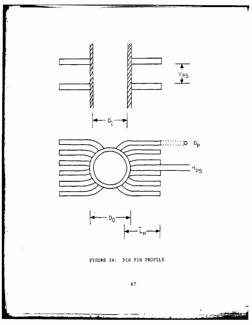
2. Pin Fins
This fin profile is shown in Fig. 34 and the descrip-
tion of the pin finned tubes is as follows:
d. =tube inside diameter -1.86 in.
65

ws
, -±
.<zc - I !D -
... -. Do
FIGURE 33: SEGMENTED FIN PROFILE
66
Vp 5
4- D0 DH
H PS
FIGURE 34: PIN FIN PROFILE
67

d = tube outside diameter = 2.00 in.0
d = fin root diameter - 2.00 in.r
Nf = pin groups per inch 2.00
Z. = average pin length = 1.015 in.P
d = pin diameter = .125 in.p
Ns = number of pins per group = 12
Vps = vertical pin spacing = .375 in.
hps = horizontal pin spacing = .20 in.
The "blocked" frontal area is
L Td 2LT N fd 1Ab = N (12)
The fin surface area is found from
Afi= (1 + dP/4) (13)
and the bare tube area is
doLT d- __Nf) . (14)
bt N ( Ns
The previously determined areas are those which are particu-
lar to the given fin profile. With this information, the
minimum gas flow area is
Ami n = Af -Ab (15)
where Af is the frontal area. The inside area available for
heat transfer per segment heat exchanger is
7wd LTA.i= iT'N- (16)si N
68
- -. . , . . .~- - --- ..- -, .
and the outside heat transfer area is
Aso Afin Ab (17)
Finally, the cross-sectional fluid flow area is calculated
from
Aff - 2[di (18)
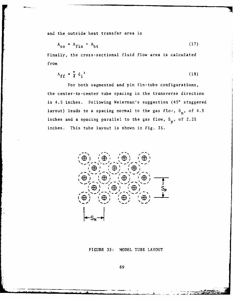
For both segmented and pin fin-tube configurations,
the center-to-center tube spacing in the transverse direction
is 4.5 inches. Following Weierman's suggestion (450 staggered
layout) leads to a spacing normal to the gas flow, Sn, of 4.5
inches and a spacing parallel to the gas flow, Sp, of 2.25
inches. This tube layout is shown in Fig. 35.
E (9) (. I
FIGURE 35: MODEL TUBE LAYOUT
69
-E - M UM

With the mass flow rates, terminal temperatures and
heat exchanger geometry established, the remainder of the
model may be solved for the number of tube rows or passes,
actual iterim temperatures, and gas side pressure drop.
C. GAS-SIDE HEAT TRANSFER/PRESSURE DROP
For both the segmented and pinned-tube profiles, the gas-
side Reynolds number is calculated initially using the gas
bulk temperature to find the gas properties. With this Reynolds
number, the segmented fin, j-factor, is obtained from a poly-
nomial fit to the data for tube layout number 5 in Ref. [12].
The j-factor is related to the heat transfer coefficient hg
by the following relationship.
j = StPr2
By introducing
= NuRePr
the previous expression can be written asNu 2/3 Nu
Reg Pr Re Pr 1/3
and
Nu = j Re Pr /3
gg
wherehd
Nu = KoKg
Therefore, a relationship may be written for the heat transfer
coefficient as follows:K 1/3
hg -j K RegPrg (19)
70
70i

For this equation all gas properties are evaluated at the film
temperature.
For the pin fin, the gas-side heat transfer coefficient
has contributions from the pins and bare tube, Equation 6-14
of Ref. [10], supplies the pin heat transfer coefficient_kf 1/3 (O
h -f- C Re Pr (20)
where the constants C and n are listed in Fig. 36.
Re C ng
0.4-4 0.989 0.3304-40 0.911 0.385
40-4000 0.683 0.4664000-40,000 0.193 0.618
40,000-400,000 0.0266 0.805
FIGURE 36: HEAT TRANSFER CONSTANTS
Properties for use with the above equation are evaluated at
the film temperature.
Eckert and Drake [Ref. 13] recommend the following rela-
tions for heat transfer from tubes in cross-flow:
o 5 0 . 38 Prf '2
Nu (0.43 + 0.50 Re )Pr (21)
for l<Re<103
71

-r- -.. .. . ..... . ... . .. .. ..
0.6 038Pr 0.25
Nu 0 .2SRe Pr P 1 (22)
for 10 3<Re<2 x 10s
For gases the Prandtl number ratio may be dropped, and fluid
properties are evaluated at the film temperature. The presure
drop for flow of gases over a bank of tubes may be calculated
from1 4
333.4 f'(G max) 2 N T UwApb (23)
Ap = pressure drop = inches H20
Gma x = mass velocity - lbm/(FT 2-s)
p = free-stream density = lbm/FT3
NT = number of transverse rows
The emperical friction factor f' is given by Jakob [Ref. 14]
as 0.18 0 *1f' = 0.25 + 0.18 ]Remax (24a)
[(Sn - d)/d jmx2
for staggered tube arrangements and
S0.08S /d o _0.15
fl = 0.044 + pRe (24b)I (.43 + 1. 1d/Sp I max
[(n - d)/d] dS
for in-line tube arrangements. For pin fins both friction
factor expressions are required. Although the tubes are
arranged in the staggered tube arrangements, the pins are
essentially an in-line configuration.
The same equation is used for the segmented fin profile
with the friction factor, f', obtained from a polynomial fit
to the data for tube layout Number 5 in Ref. [12], (Fig. 5).
72
" --

D. WATER-SIDE HEAT TRANSFER
Water-side heat transfer involved the heating, boiling and
superheating of water or steam. A multitude of correlations
are currently available to describe each individual mode.
Although not prohibitive, a literature review resulted in
several being chosen to represent the S.S.T. model.
With little known about this boiler type, four heat transfer
correlations were candidates to represent the heating mode.
One could reasonably surmise that the laminar situation is the
most probable; turbulent correlations however, are also con-
sidered. An empirical correlation based on experimental data
that takes into account the effect of varying physical proper-
ties and free convection is listed below [Ref. 15]:
kf 33 4 /Prf, ji~ 3 2go,~T.
hH 0 = .17 k4/( " 2g-- B AT (25)
This relationship is valid for heating in vertical upflow for
Re<2000. Water properties are evaluated at the film tempera-
ture; Prw, at the wall temperature.
The work done by Sieder and Tate [Ref. 16], resulted in
two simple empirical relationships which take into account
fluid property variations. For laminar heat transfer in tubes,
use the following equation
hH0 - 1.86 k (RePr) () ( (26)
ford.
RePr --I >10T
73

and for turbulent heat transfer
hH20 M .027 k Re Pr (27)
for
7<Pr<16.700
Re>10,000
For both situations, all fluid properties are evaluated at the
mean bulk temperature of the fluid, except w , which is evalua-
ted at the wall temperature. Recommended by Dittus and Poelter
[Ref. 17] for turbulent flow is
3k Re Pr (28)hH20 02 - Re Pr
The properties in this equation are evaluated at the fluid bulk
temperature. This variety of expressions allows the designer
to study a greater range of possibilities.
Consider now the conditions under which boiling will be
initiated in the vertical heated tube. No boiling can occur
while the temperature of the heating surface remains below the
saturation temperature of the fluid at that particular location.
It should be realized that fully developed subcooled boiling
is not initiated whenever the heated surface first exceeds
the saturation temperature. As shown in Fig. 37, a region of
"partial boiling" exists between the subsaturation zone, A,
and fully developed subcooled boiling, B. This "partial boil-
ing" zone consists of comparatively few nucleation sites and
in this zone, a proportion of the heat would be transferred
by normal single-phase convection between patcher or bubbles.
74

F"' do w - ,Od
%% (Rgion )
%
F
A////
Partial iing
FIGURE 37: SURFACE HEAT FLUX VS. INLET SUBCOOLING
For forced convective flow, Bergles and Rohsenow (Ref. 18]
developed a criterion based on analysis by Hsu [Ref. 19] and
Han [Ref. 20] for the incipience of boiling. In this work,
Bergles proposed a convenient numerical expression to determine
the wall superheat required to initiate boiling. This expres-
sion is for the steam-water system in the 15-2000 psia pres-
Oonb - 15.60 p (T wall - Tsat) P ) (29)
75

where 0 onb (Btu/hr.ft2 ) is the heat flux to cause nucleation
at a wall superheat T wall Tsa t and at a system pressure p
(psia).
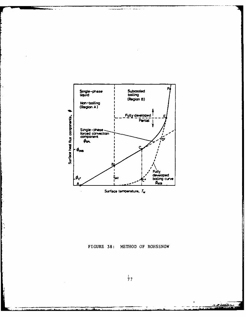
As the surface temperature is increased further, the whole
surface is covered by bubble sites, boiling is "fully developed"
and the single-phase component reduces to zero. In the "fully
developed" boiling region, velocity and subcooling have little
or no effect on the surface temperature as observed experimen-
tally. Throughout the partial boiling region Rohsenow [Ref.
21] suggests that
0Total = OSPL + 0SCB
where 0Total is the total average surface heat flux, 0 SPL is
the average surface heat flux transferred by single-phase
convection, and 0SCB is the average surface heat flux trans-
ferred by boiling. This method of superposition, shown in
Fig. 38, utilizes the single-phase component given by
OSPL ' hc (Twall - Tbulk)
where h is found by the familiar Dittus-Poelter equation.
The boiling contribution was successfully correlated with
the experimental data using the equation suggested by Rohsenow
[Ref. 22] for staturated nucleate pool boiling
0SCB I g(f - )1Tall Tsatd] 3 (30)
SfgPr Csf Ifg
where Csf is a constant described by the liquid surface com-
bination. The data reduced and correlation used a value of
Csf - .006. The surface-tension is calculated from (Ref. 23].
76
Single-phase I SubcooledLiquid I boiling
(Region 8)
Non-boboiinging
I- - Oc
forcedc tm iraueT
FIUEC8OMTOMOMOHEO
OW77
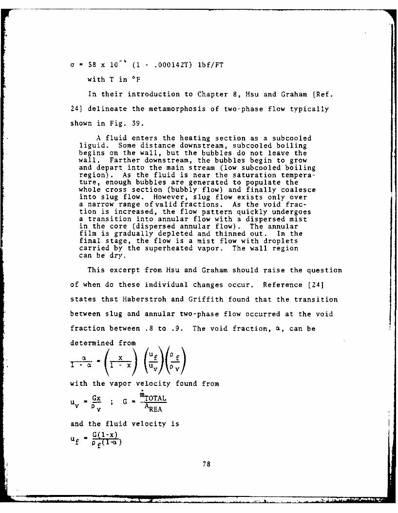
a = 58 x 10 (1 .000142T) lbf/FT
with T in *F
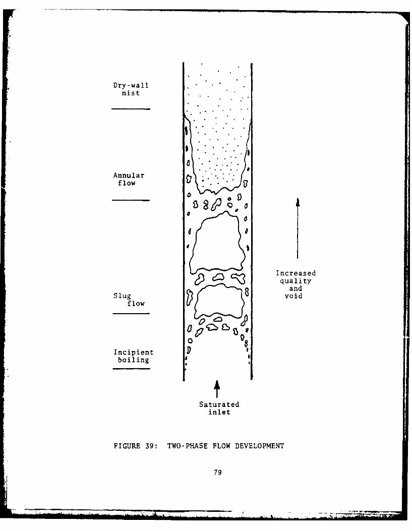
In their introduction to Chapter 8, Hsu and Graham [Ref.
24] delineate the metamorphosis of two-phase flow typically
shown in Fig. 39.
A fluid enters the heating section as a subcooledliguid. Some distance downstream, subcooled boilingbegins on the wall, but the bubbles do not leave thewall. Farther downstream, the bubbles begin to growand depart into the main stream (low subcooled boilingregion). As the fluid is near the saturation tempera-ture, enough bubbles are generated to populate thewhole cross section (bubbly flow) and finally coalesceinto slug flow. However, slug flow exists only overa narrow range of valid fractions. As the void frac-tion is increased, the flow pattern quickly undergoesa transition into annular flow with a dispersed mistin the core (dispersed annular flow). The annularfilm is gradually depleted and thinned out. In thefinal stage, the flow is a mist flow with dropletscarried by the superheated vapor. The wall regioncan be dry.
This excerpt from Hsu and Graham should raise the question
of when do these individual changes occur. Reference [24]
states that Haberstroh and Griffith found that the transition
between slug and annular two-phase flow occurred at the void
fraction between .8 to .9. The void fraction, a, can be
determined from
with the vapor velocity found from
u Gx G mTOTALv v AREA
and the fluid velocity isuf G(l-x)
f78
78
....... ......
Dry-wallmist
Annularflow
Increasedcz 3 quality• ,and
Slug voidflow
o d08Incipientboiling 0
Saturatedinlet
FIGURE 39: TWO-PHASE FLOW DEVELOPMENT
79
4 _ . . . _ l m . .
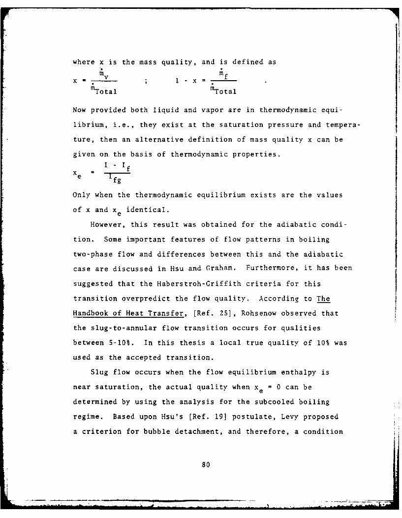
where x is the mass quality, and is defined asm vv mfxl-xmTotal mTotal
Now provided both liquid and vapor are in thermodynamic equi-
librium, i.e., they exist at the saturation pressure and tempera-
ture, then an alternative definition of mass quality x can be
given on the basis of thermodynamic properties.
I - fe I
fg
Only when the thermodynamic equilibrium exists are the values
of x and x e identical.
However, this result was obtained for the adiabatic condi-
tion. Some important features of flow patterns in boiling
two-phase flow and differences between this and the adiabatic
case are discussed in Hsu and Graham. Furthermore, it has been
suggested that the Haberstroh-Griffith criteria for this
transition overpredict the flow quality. According to The
Handbook of Heat Transfer, [Ref. 25], Rohsenow observed that
the slug-to-annular flow transition occurs for qualities
between 5-10%. In this thesis a local true quality of 10% was
used as the accepted transition.
Slug flow occurs when the flow equilibrium enthalpy is
near saturation, the actual quality when xe = 0 can be
determined by using the analysis for the subcooled boiling
regime. Based upon Hsu's [Ref. 19] postulate, Levy proposed
a criterion for bubble detachment, and therefore, a condition
80
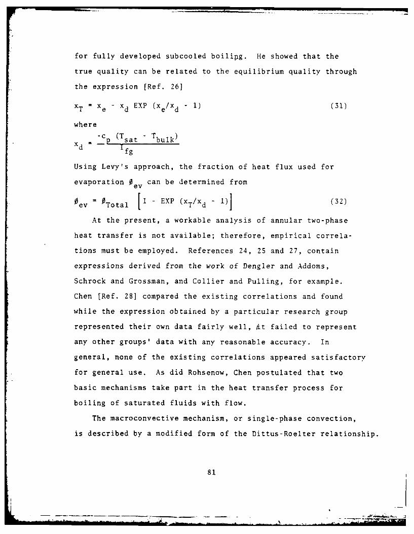
for fully developed subcooled boilipg. He showed that the
true quality can be related to the equilibrium quality through
the expression [Ref. 26]
X T = X e - xd EXP (x e/Xd - 1) (31)
where
xd = -c P (Tsat - Tbulk)Ifg
Using Levy's approach, the fraction of heat flux used for
evaporation 0ev can be determined from
0 = Total [1 - EXP (xT/Xd - 1)1 (32)
At the present, a workable analysis of annular two-phase
heat transfer is not available; therefore, empirical correla-
tions must be employed. References 24, 25 and 27, contain
expressions derived from the work of Dengler and Addoms,
Schrock and Grossman, and Collier and Pulling, for example.
Chen [Ref. 28] compared the existing correlations and found
while the expression obtained by a particular research group
represented their own data fairly well, 4t failed to represent
any other groups' data with any reasonable accuracy. In
general, none of the existing correlations appeared satisfactory
for general use. As did Rohsenow, Chen postulated that two
basic mechanisms take part in the heat transfer process for
boiling of saturated fluids with flow.
The macroconvective mechanism, or single-phase convection,
is described by a modified form of the Dittus-Roelter relationship.
81
- -
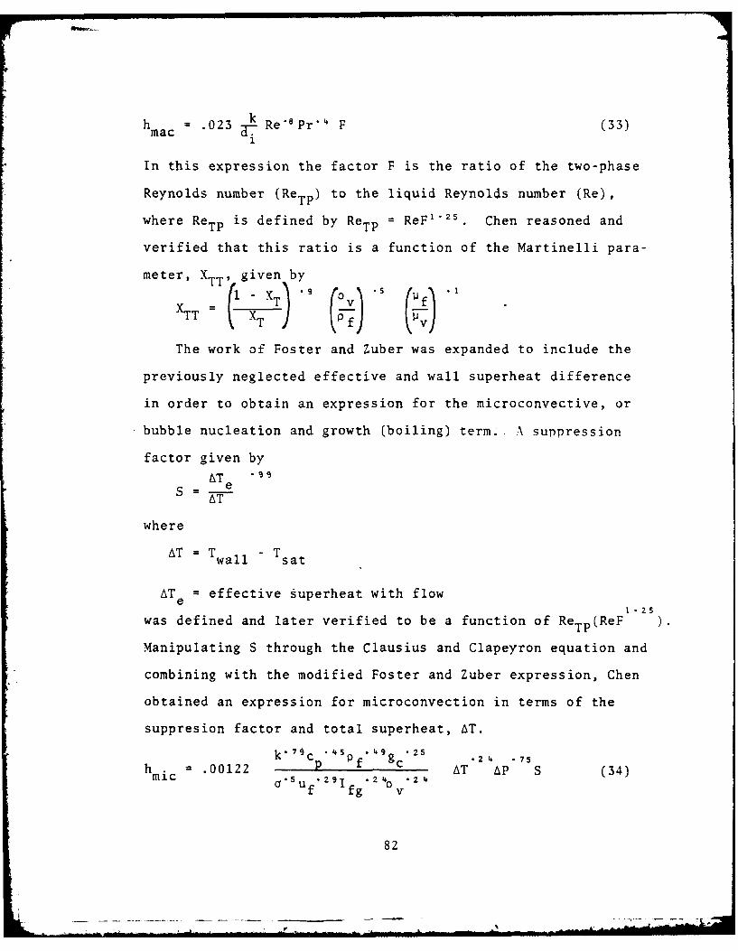
h a 023 k Re'Pr" F (33)1
In this expression the factor F is the ratio of the two-phase
Reynolds number (ReTP) to the liquid Reynolds number (Re),
where ReTP is defined by ReTP = ReF '25 . Chen reasoned and
verified that this ratio is a function of the Martinelli para-
meter, X TV given by. )T . .9 S.I
xTT = T
The work of Foster and Zuber was expanded to include the
previously neglected effective and wall superheat difference
in order to obtain an expression for the microconvective, or
bubble nucleation and growth (boiling) term.. A surpression
factor given by
AT e
AT
where
AT = Twall T sat
ATe - effective uperheat with flow1 . 25
was defined and later verified to be a function of ReTP(ReF
Manipulating S through the Clausius and Clapeyron equation and
combining with the modified Foster and Zuber expression, Chen
obtained an expression for microconvection in terms of the
suppresion factor and total superheat, AT.
kmc . 0 2 p " g .2' , .75
= 00122 k '.4 P('.g 2 5 AT AP S (34)i auf 29Ifg 2 4O v.2 4
82
tl~ u. . . -'- k, -' - i - ' J . .. . . ... : .. . . .. ' - l - l . . .. V
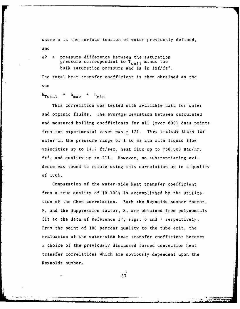
where a is the surface tension of water previously defined,
and
AP pressure difference between the saturationpressure correspondint to T wall minus the
bulk saturation pressure and is in lbf/ft2.
The total heat transfer coefficient is then obtained as the
h Total h ha i
This correlation was tested with available data for water
and organic fluids. The average deviation between calculated
and measured boiling coefficients for all (over 600) data points
from ten experimental cases was + 12%. They include those for
water in the pressure range of 1 to 35 atm with liquid flow
velocities up to 14.7 ft/sec, heat flux up to 760,000 Btu/hr.
ft2 , and quality up to 71%. However, no substantiating evi-
dence was found to refute using this correlation up to a quality
of 100%.
Computation of the water-side heat transfer coefficient
from a true quality of 10-100% is accomplished by the utiliza-
tion of the Chen correlation. Both the Reynolds number factor,
F, and the Suppression factor, S, are obtained from polynomials
fit to the data of Reference 27, Figs. 6 and 7 respectively.
From the point of 100 percent quality to the tube exit, the
evaluation of the water-side heat transfer coefficient becomes
a choice of the previously discussed forced convection heat
transfer correlations which are obviously dependent upon the
Reynolds number.
83
E. OVER-ALL HEAT TRANSFER
Newton's law of cooling may be written as
Q =hAAT
It is often convenient to express the heat transfer rate for
a combined conductive-convective problem in this form with h
replaced by an overall heat transfer coefficient U.
The primary objective in the thermal design of heat ex-
changers is to determine the necessary surface area required
to transfer heat at a given rate for given fluid temperatures
and flow rates. The utilization of U facilitates this procedure
in the above fundamental heat transfer relation
Q = UAATLM
where ATLM is the average effective temperature difference
known as the log-mean temperature difference.
It is well known that the primary purpose of fins is to
increase the effective heat transfer surface area exposed to
a fluid in a heat exchanger. The performance of fins is often
expressed in terms of the fin efficiency, nf
[actual heat transfer]heat transfer if entire fin wereat the base temperature
Analytical expressions for nf are readily obtained for several
common fin configurations.
For this model, both segmented and pin fins are considered
to have ends that are at the free-stream temperature. Using
a corrected length L (as was suggested by Harper and Brown)c
the insulated tip fin equation can be utilized, as follows
84
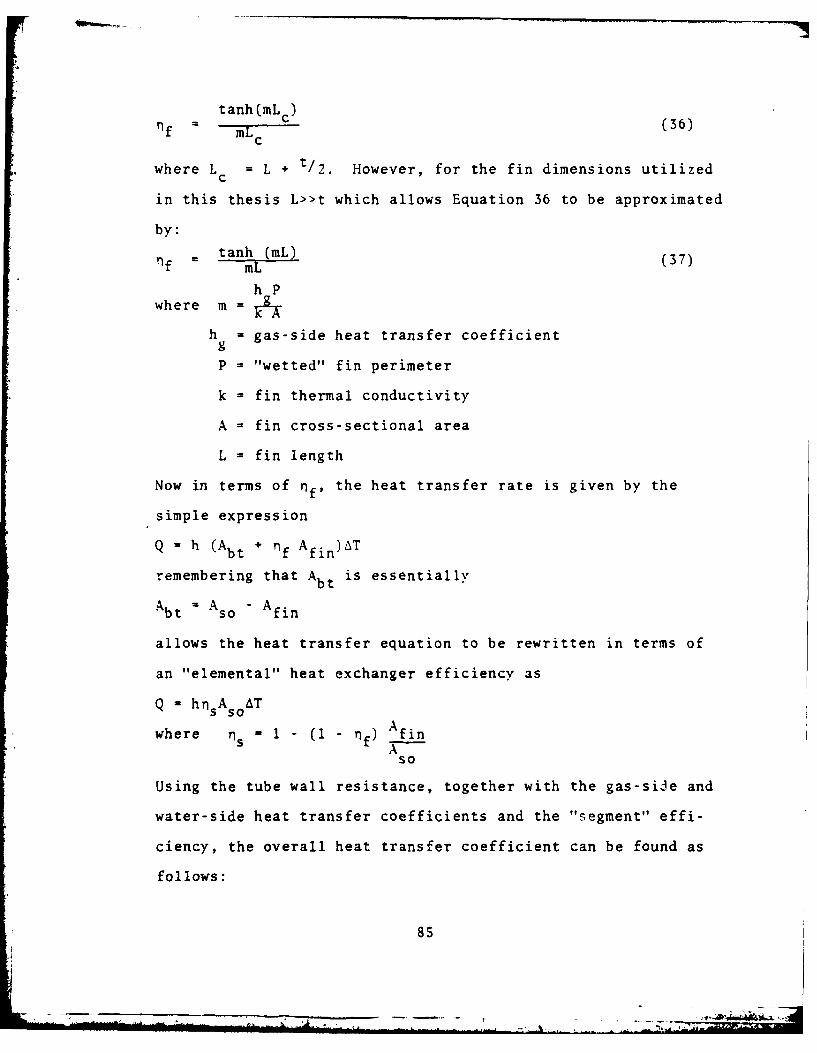
tanh (mLC) (36)qf = mL c 6
where L = L + t/2. However, for the fin dimensions utilized
in this thesis L>>t which allows Equation 36 to be approximated
by:
- tanh (mL) (37)- mL
h Pwhere m =
h = gas-side heat transfer coefficientg
P = "wetted" fin perimeter
k = fin thermal conductivity
A = fin cross-sectional area
L = fin length
Now in terms of ff, the heat transfer rate is given by the
simple expression
Q - hi (Abt +lf Afi)AT
remembering that Abt is essentially
Abt = Aso - A fin
allows the heat transfer equation to be rewritten in terms of
an "elemental" heat exchanger efficiency as
Q = hns A soAT
where ns M 1 - (1 - nf) fin
so
Using the tube wall resistance, together with the gas-side and
water-side heat transfer coefficients and the "segment" effi-
ciency, the overall heat transfer coefficient can be found as
follows:
85
-7=277.

(a) in terms of the inside area
Uo. A 1 (38)1 +Asi 01n(d/d si+ +
hH20 27ktube Ls so sh g
(b) in terms of the outside area
Uo 1 (39)o Aso A ln(do/d.)+ +
sihH20 2ktube s
Using the effectiveness - NTU method, an average "segment"
effectiveness is calculated from equations 7a or 7b; if a
phase change is occurring, equation 8. The expression for e
is now used in an iterative fashion. Each time an effective-
ness is calculated it is compared to the previously found £
until a difference of less than .001 is obtained. This differ-
ence represents the convergence of the "elemental" heat exchanger
effectiveness. During each iteration, the gas and water
temperatures are determined in the following way. The total
heat transfer rate is, per segment,
Qs 0c ATmin max
then the outlet gas temperature is
Tgou t 0 Tgin - Qs/Cgas (40a)
and for the water/steam temperature
Twouy a TWin + Qs/CH20 (40b)
or if boiling is present, the outlet enthalpy of water is
found from
out in + QS/H 2 0 (40c)
86
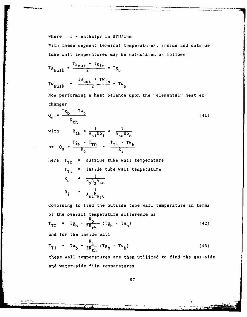
where I * enthalpy in BTU/lbm
With these segment terminal temperatures, inside and outside
tube wall temperatures may be calculated as follows:
Tgou t + Tg in .Tg
TW out ' TWinTWbulk 2 b TWb
Now performing a heat balance upon the "elemental" heat ex-
changerTgb, Twb (1IQs gbRthw (41)
Rth
iwith Rt Ai~ AsoUo
or Tgb TT = TTi - TwbR0
i
here TTO outside tube wall temperature
TTi - inside tube wall temperature
R 0 nsh 1Ag so
R1Ri A Asi hH2 0
Combining to find the outside tube wall temperature in terms
of the overall temperature difference asRo
TTOa Tgb - t (Tgb Twb) (42)
and for the inside wall
R.T Ti = w Tb + r)h ( T g b -TVb (43)
th
these wall temperatures are then utilized to find the gas-side
and water-side film temperatures
87
- - ---- " . ... . --- - -. ----1

Tgb + TToTgf 2
Twb + TTiand Twf = b2T
which are used in calculations requiring fluid property evalua-
tion of the film temperature.
This completes the required calculations for the "elemental"
heat exchanger. The final values of the water-side variables
are used as the inlet conditions for the next segment, and the
whole of the aforementioned procedure is repeated N (total
number of elemental heat exchangers per tube) times. This re-
presents the end of the tube.
At this point an overall tube heat balance is written based
upon enthalpy considerations. The total heat transfer rate is
found fromN
QTotal j*i Qs.
and QTotal = mH20 (exit - inlet
solving for the water mass flow rate yields
QTotal ibm
HO I exit Iinlet r-
Obviously as the gas transverses the rows of tubes in the
heat exchanger, its temperature decreases, producing a corres-
ponding decrease in the gas-to-water temperature difference.
The heat transfer rate being a function of this temperature
difference also becomes less, however, the inlet and exit
conditions are specified design parameters which remain con-
stant. Since one of the assumed parameters was a water-side
88
- - ~- ----- ---- - - .-

Reynolds number, this step allows for the actual mass flow
rate, and Reynolds number to be compared with the original.
If the relative error defined here as
H20 calc -1 20 INITIALE
r "~H20 calc
is greater than 5%, the entire set of calculations is repeated
using the calculated mass flow rate as the initial m H20 In
this manner, a profile of the water mass flow rates is found
on a row basis for this type of heat exchanger.
A matrix of the segment outlet gas temperatures is utilized
at the inlet of the next row. The total number of rows is
obtained when the following condition is satisfied
T0 * ~ ou Tg i Design outlet gas temperature
89

III. RESULTS AND CONCLUSIONS
A. BACKGROUND
The foregoing model was applied in a computer simulation
program witten in BASIC for the Hewlett Packard 9845 model B
desktop computer. Inclusive are a set of supporting subpro-
grams for the determination of water, steam and air properties.
Finally, one subprogram was included to provide a choice for
the thermal conductivity of both the selected fin and tube
metal. With the establishment of the design variables to test
the model and to develop an understanding of the behavior of
the S.S.T., the program was activated to produce a heat ex-
changer design.
A review of the initial results revealed that the proposed
model required modification in order to produce more realistic
simulated data. The problem arose from the attempt to match
Rohsenow's and Chens correlation at 10% steam quality. It is
well known that boiling heat transfer is associated with rather
high heat transfer -coefficients, and these results reflected
this fact up to the 10% quality point. The heat transfer co-
efficients were of the order of 20,000 BTU/HR FT2 OF. However,
upon program transfer to the Chen correlation for the
determination of the water-side heat transfer coefficient, these
values were of the order of 6-20 BTU/HR FT2 OF. Obviously,
this tremendous diference in magnitudes is definitely not a
90
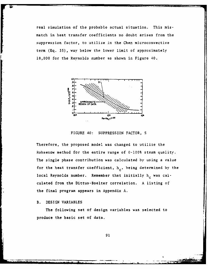
real simulation of the probable actual situation. This mis-
match in heat transfer coefficients no doubt arises from the
suppression factor, to utilize in the Chen microconvective
term (Eq. 35), way below the lower limit of approximately
18,000 for the Reynolds number as shown in Figure 40.
1.0 1 T I m I I 'SA-
.6
2-
REGIO OFt FDATA
0
.5
FIGURE 40: SUPPRESSION FACTOR, S
Therefore, the proposed model was changed to utilize the
Rohsenow method for the entire range of 0-100% steam quality.
The single phase contribution was calculated by using a value
for the heat transfer coefficient, h c , being determined by the
local Reynolds number. Remember that initially h c was cal-
culated from the Dittus-Boelter correlation. A listing of
the final program appears in Appendix A.
B. DESIGN VARIABLES
The following set of design variables was selected to
produce the basic set of data.
91
1. S.S.T. Operating Pressure
The previous work of Combs [Ref. 7] indicated that the
optimal operating pressure ranged from 600-800 psig. For this
simulation, 600 psig was selected.
2. Frontal Diminsions
Space constraints for a DD-963- type engineroom limits
the maximum heat exchanger width to 12 feet. To be consistent
with this constraint, the frontal dimension of 3.658 m x lm
(12'x3.2808') was selected for the design.
3. Gas Flow Rate and Temperatures
The outlet from the gas turbine was taken to be 145
lbm/sec (522,000 lbm/hr) at 900'F under steady state and steady
flow conditions.
4. Superheater Outlet Steam Temperature
The target superheat at the outlet was specified to be
S0OF. At 600 psig this corresponds to 536*F. This amount of
superheat will vary with water-side mass flow rate.
S. Water Inlet Temperature
The water inlet temperature was fixed at 50'F subcooling
or 4360F.
6. Fin Geometry
The segmented fin profile was selected for the gas-side
heat transfer.
92
C. THE DATA SET
A set of data was produced for the combination of design
variables just discussed. This data was generated by varying
the inlet Reynolds number, or if one prefers, the inlet mass
flow rate, and was the result from the investigation of 60
different such numbers. The following set of output variables
was considered.
1. Gas bulk temperature variation
2. Gas-side heat transfer coefficient
3. Overall heat transfer coefficient based upon the out-
side area
4. Tube wall temperature variation
S. Water/steam mass flow rate
6. Water-side heat transfer coefficient
7. Overall heat transfer coefficient based upon the inside
area
8. Inside surface heat flux
9. Water-bulk temperature variation
10. Thermodynamic quality variation
This investigation included a Reynolds number range of
75 to 1650. Figure 41, shows graphically the water/steam mass
flow rate corresponding to each Reynolds number in order to
provide information concerning the range of mass flow rates
involved. It should be re-emphasized that these Reynolds
numbers are those associated with the water properties at the
tube inlet temperature of 436 0F. The outlet Reynolds number
93
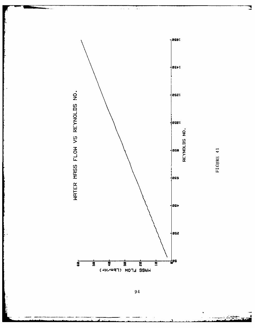
0zM
z
00 z
U) U
0 -
LAI
U) -
949

becomes simply Reout = Re. in INLET
in"EXIT
A logical expectation is the decreas~e in outlet superheat
with an increase in mass flow rate. This trend is displayed
in figure 42a. Point A corresponds to a Reynolds number of
310 and a superheat of 610; d.,hereas, point B, 380 and 91.
Figures 43 and 44 show that there is very little difference in
the water-side heat transfer coefficient for these two values
of Reynolds numbers during the preheating of the water toward
the saturation temperature. However, the value of h represen-
tative during superheating for Re = 380 is approximately twice
the value of h for Re 310 (Figures 45 and 46).
The logical question to be raised at this point is why
this difference e.,ists. Outwardly, there definitely appears
no logical explanation. Although not a specific part of the
data set, the Reynolds number variation with axial position
should have been plotted. It was observed on the CRT of the
computer that in this "transition" region the Reynolds number
gradient steadily increased along the tube for the inlet
values of 310 and 380. This observation revealed the greatest
magnitude of the Reynolds number was obtained at the point of
100% steam quality inside the tube.
For a Reynolds number of 310 the maximum value obtained
was approximately 2100, whereas a Reynolds number of 380 the
maximum value obtained was approximately 3300. The effect on
heat transfer is observed as the water-side tube flow trans-
verses from the laminar to turbulent regime, with the steam
95
AD-AL07 454 NAVAL POSTGRADUATE SCHOOL. MONTEREY CA F/S 13/1DESIGN MODEL FOR THE HEAT TRANSFER ZN A SHORT STRAIGHT Tuft BOI- ETC(U)JUN 81 L W VOLLMERUNLASSIFIED LIIIIIIIIIII
I2lflflflflflflflflflflflEllllllEEE~llEEIIIIIIIIIIIIlEIIIIIIIIIIIIuEIIIIIIIIIIIIlEIEEIIh hh
III I1.0 2IIIII8 B.5
mmmli1111111112.* 0
fL- 25 1.4'~ .
MICROCOPY RESOLUTION TEST CHARTNATIONAL BURIAU 01 TAN[IARDr 16 A

0z C
ag 0> z
II
a:,
a.4
(4.) lW3HH3dfls
96

aw
a.
0 w
CL
a:
I--.
.9.
-28
(4/)l M-JSW
U97

9
(7 C
2011
(J,/%J-bS/JH/ni., H aS-~W
777

g*9
0
CW) go
0zz
>_ 0
o 'go
U , /%d-SJHn.e 0 Cl-~W
99.

zz
z~ I-
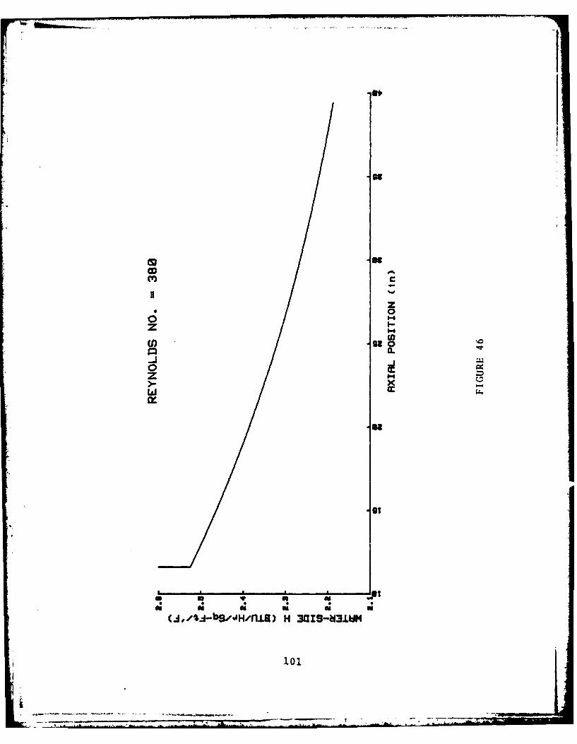
cww
zz
0z I
-2
1011

tnt
gm8
0' CC
z m-
>--J
ixx
(Ca,~ 3HflbM3dW3 WI S >flfl 3JM
102
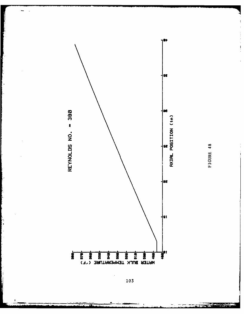
St0
zz>--
oo
103

BOOT
-0-8
cr.
-AJ
00
o
L))0
Nu)NII~ WX
104g

-eggs
1-4
-j
zS) 0
-68
o w
z
0
Cut) N111S ~ SOX
105
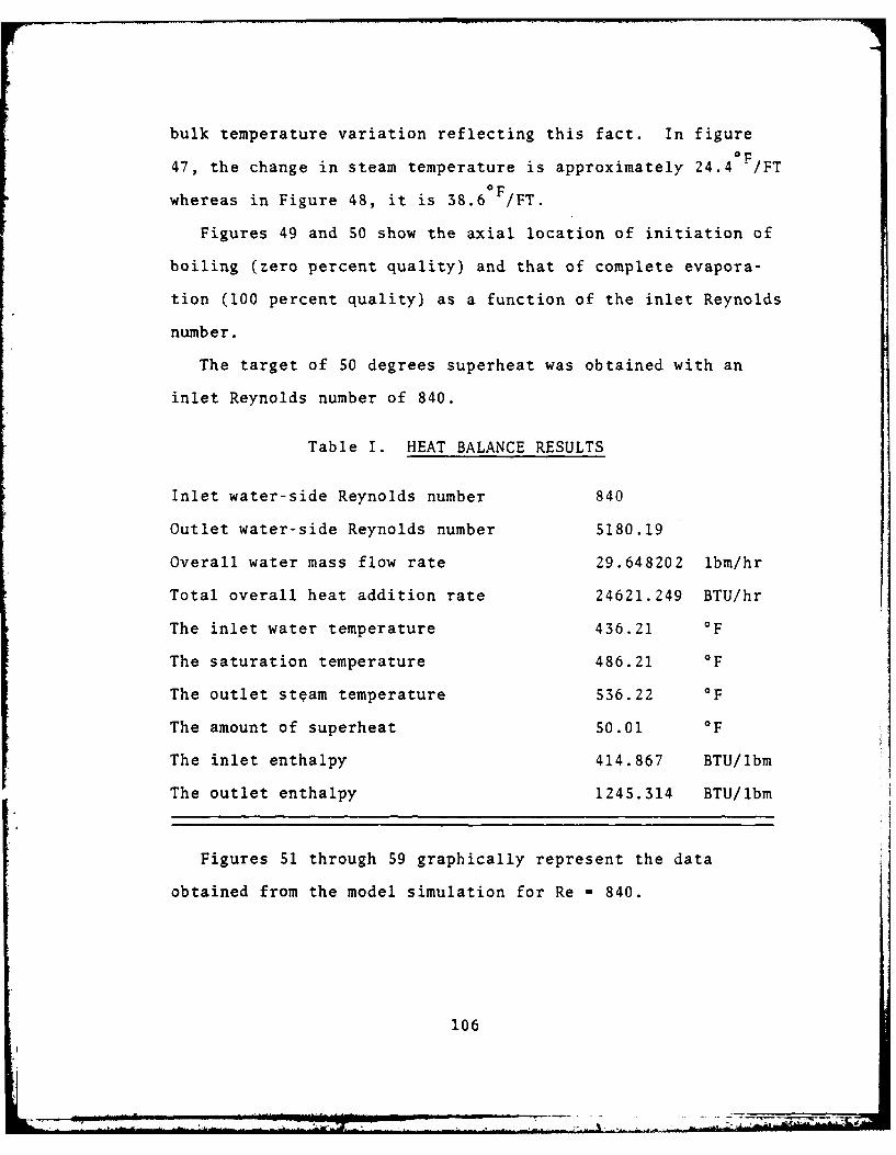
bulk temperature variation reflecting this fact. In figure
47, the change in steam temperature is approximately 24 .4 OP FT
whereas in Figure 48, it is 38.60 F /FT.
Figures 49 and 50 show the axial location of initiation of
boiling (zero percent quality) and that of complete evapora-
tion (100 percent quality) as a function of the inlet Reynolds
number.
The target of 50 degrees superheat was obtained with an
inlet Reynolds number of 840.
Table I. HEAT BALANCE RESULTS
Inlet water-side Reynolds number 840
Outlet water-side Reynolds number 5180.19
Overall water mass flow rate 29.648202 lbm/hr
Total overall heat addition rate 24621.249 BTU/hr
The inlet water temperature 436.21 OF
The saturation temperature 486.21 O
The outlet steam temperature 536.22 O
The amount of superheat 50.01 OF
The inlet enthalpy 414.867 BTU/lbm
The outlet enthalpy 1245.314 BTU/lbm
Figures 51 through 59 graphically represent the data
obtained from the model simulation for Re =840.
106

These figures show the axial distribution of the associated
variables under the prescribed design conditions for the seg-
mented fin profile.
Table 2: TUBE/FIN DIMENSIONS AND AREAS
The selected fin profile is the segmented-fin
The outside tube diameter 2 Inches
The inside tube diameter 1.86 Inches
The tube length 39.37 Inches
The total outside tube area 1.71889 Square Feet
The total inside tube area 1.59857 Square Feet
The fin root diameter 2 Inches
The number of 'fins' per inch 5.94
The number of 'segments' per fin 38
The fin height 1.015 Inches
The fin thickness .048 Inches
The transverse tube pitch 4.5 Inches
The longitudinal tube pitch 2.25 Inches
The fin outside diameter 4.03 Inches
The fin segment width .17 Inches
The length of cut from fin tip .82 Inches
The total integer number of fins 234 Fins
Actual tube length will be 39.394 Inches
The fin thermal conductivity 144 BTU/Hr.Ft./F
The tube thermal conductivity 20 BTU/Hr.Ft./F
107*.

Calculated heat transfer areas in square feet:
Total heat exchanger frontal area 39.394
Total fin area 26.9509S1
Total bare tube area 1.228802
Total outside tube area 28.179753
Single fin area .115175
Outside 'elemental' area .120426
Inside 'elemental' area .006831
'Elemental' frontal area .005261
'Elemental' blocked area .003015
'Elemental' minimum gas-flow area .002246
This data shows what would reasonably be expected. That
is, relatively low values for heat transfer coefficients and
heat flux for the preheat and superheating sections and high
values for the boiling section.
D. CONCLUSION
The short straight tube model and the accompanying graphi-
cal data provide the basic framework for additional study of
the stagnation, or S.S.T boiler. This model, as formulated,
provides a fairly reasonable estimate of the possible perfor-
mance for the fin-tube configuration considered. Performance
estimates are encouraging even considering the assumptions
involved.
108
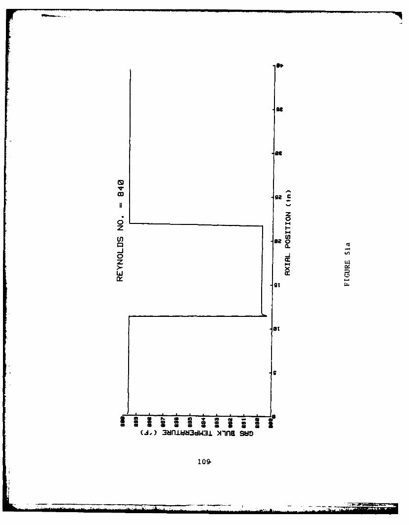
zz
'-'A
0l
zL'-
ra
colon Z(J,)3mnlM~dW1 mie s,
loo.-
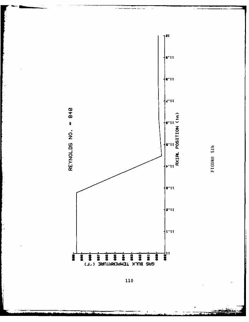
CDC
zzc*21 0
0 T.
U, 6*11
La.IT
1101

IOD
U."u
0 0rz I
gso t(J,)3unIN~dW1 mia su
7-J
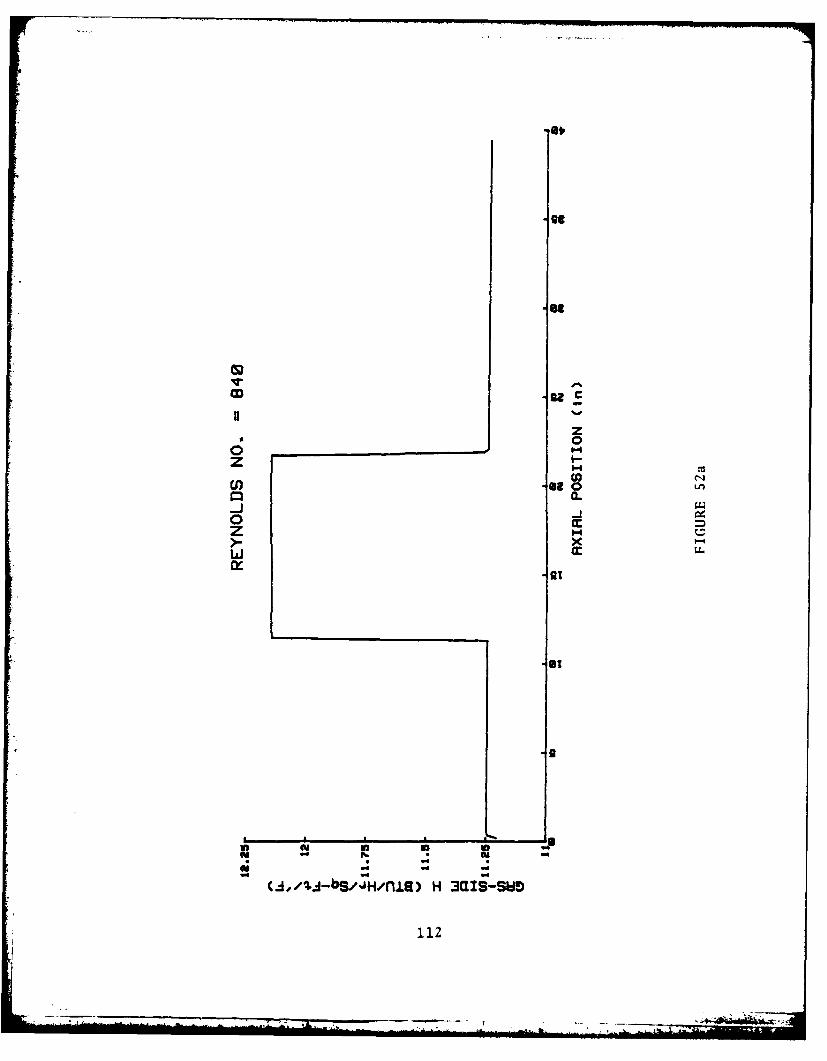
z0
z I
0 0m
x -x
Liin
Hc3k:SW
112:

CL
0 . -
zz>- 0
U) /U-SJHna H 90-w
113.

CDC
u
0z I
LI-4
Va.
-9,1
o1 l L 6 A 6 "z j/+-SQ/i)H3i-w
114

i
(J,/J-b/JH/iR)n 3asiz
*110
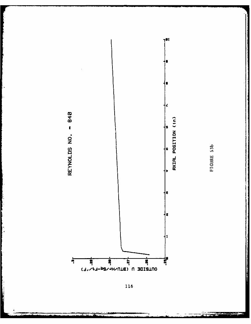
ca:
z6 0
z I
-J1-
LLI
(4,/%4A-bS/JH/fl±) nl 3UisiLfo
116
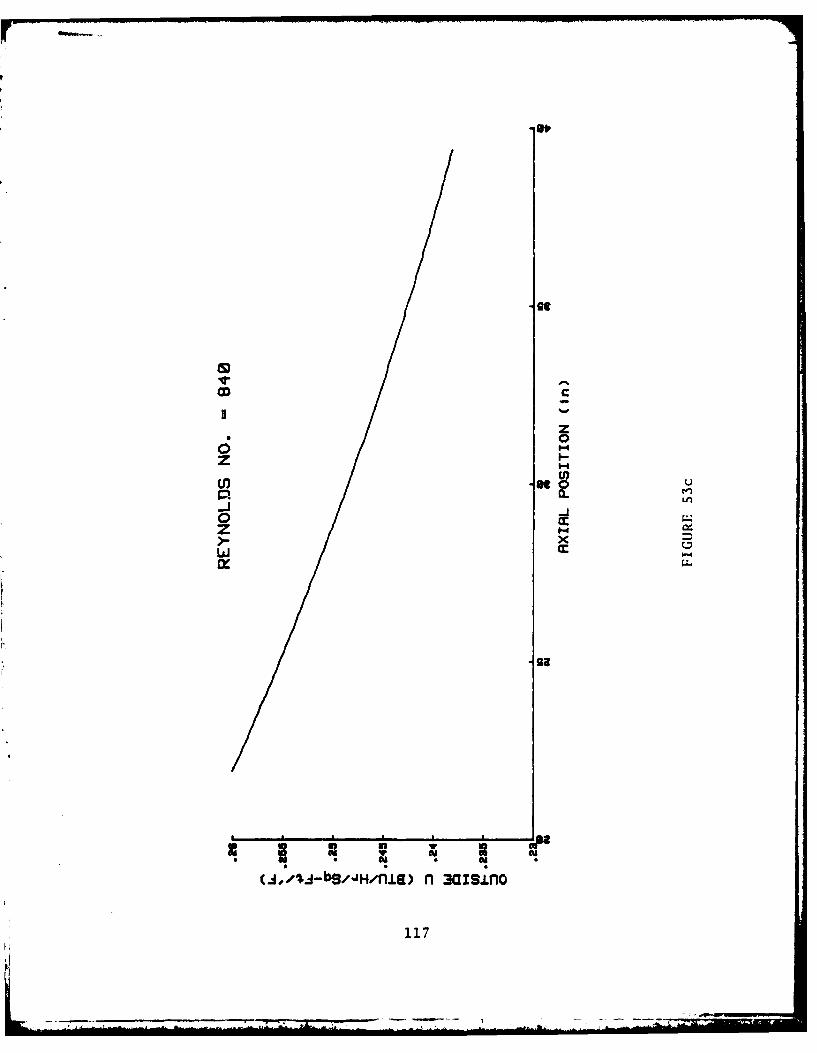
CDC
zz-B 0
0 ccz I
-J9
0 -u
z .,s-sj/na asn
117
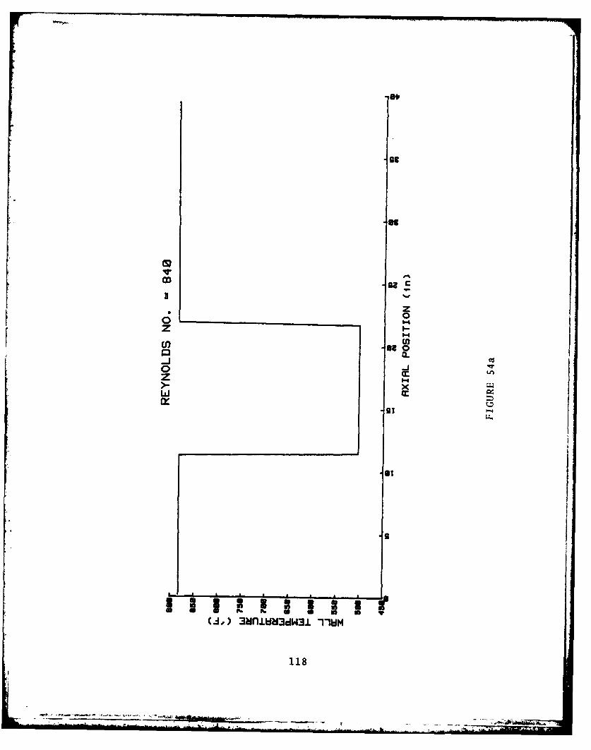
OD 93NZ
z
z I
0-JM Lfn
>- x
118

-9
CL
'Kn
c
(A. 3blbU,31IW
119'
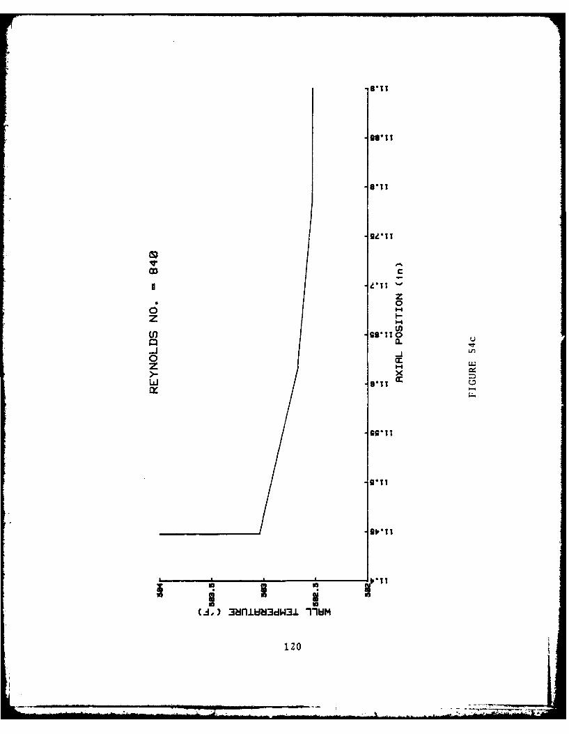
Wl *IT
CD cVI Z
z*00
z I>-'-4
(A. 3uiUW1 mu
120I0
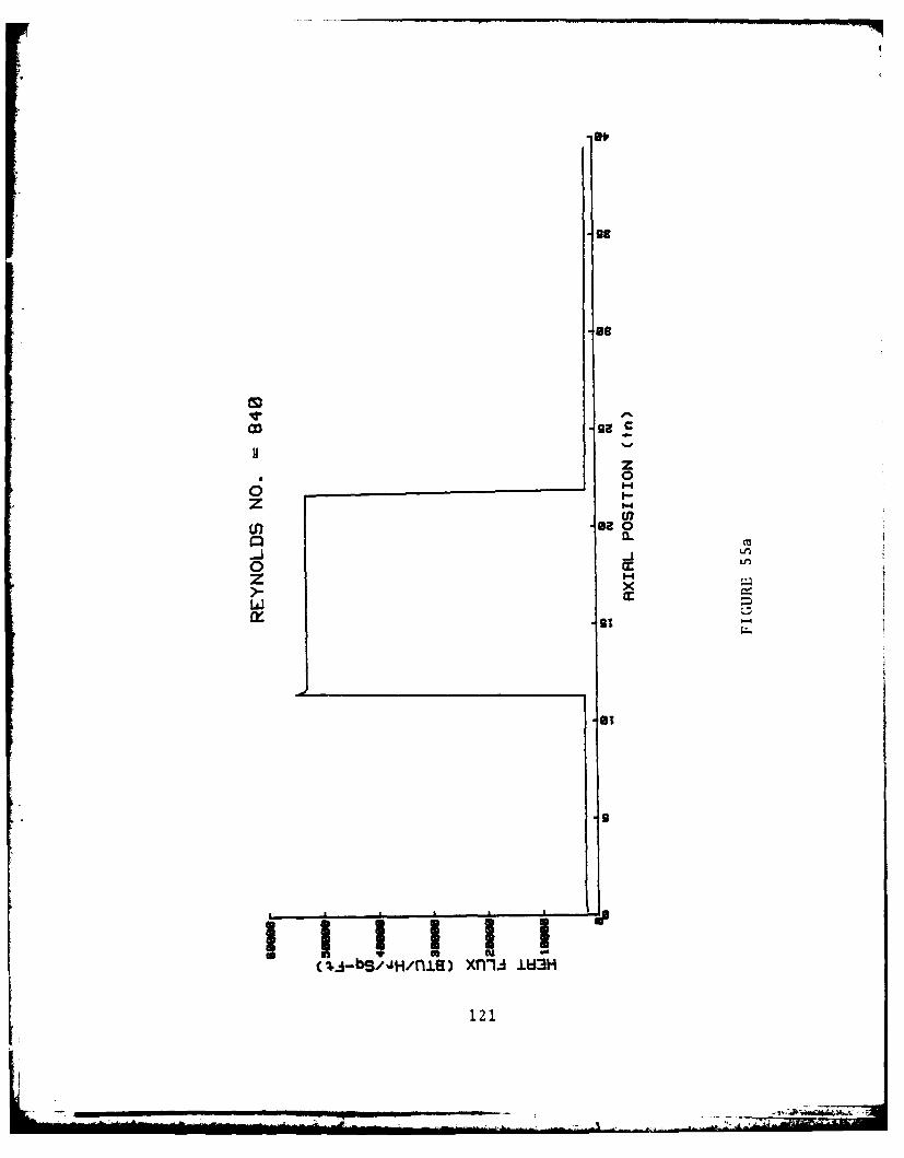
z* 0
z 1-4
o Lf
z -wx
al
121

CDC
-9 0
a.o LA
0 mw
>_ +I
%.j-s/jmn.Lg xnn IW3
122I

-8,*11
CDC
z* 0
z I
rn-I
0.
zx
123
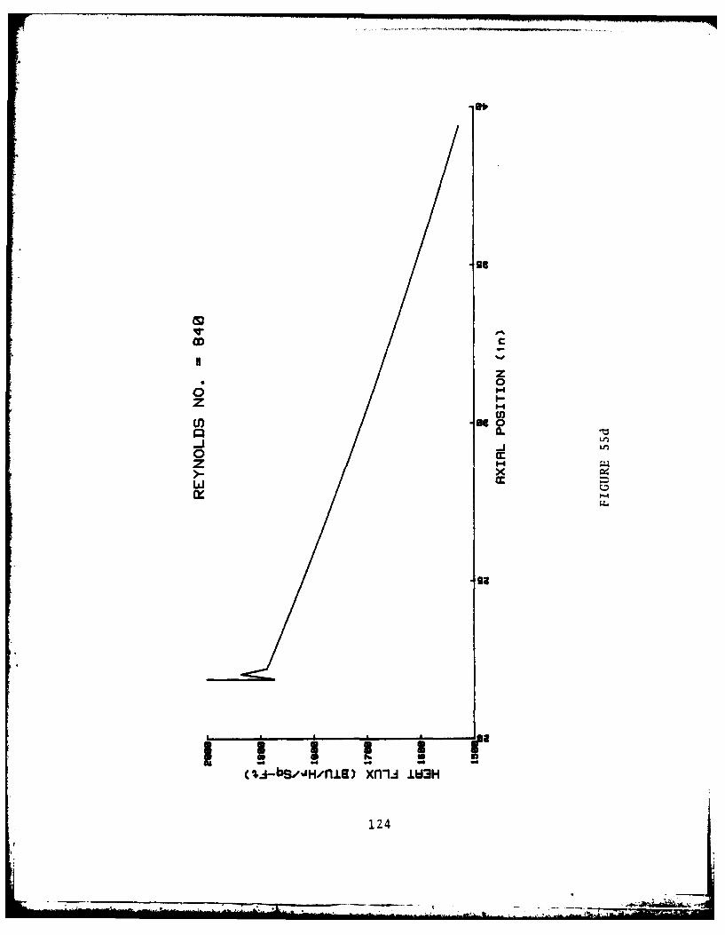
C;C
zz
InnJU)00
x
LLI
(q.4-bS,/JH/flJ.) xfill4.3H
124

ODE
-Be0
Im~B CLn
zz* 0o_ m__ _ _ _ _ u-
z Ii-
r 3a IS-831U
U) 12S

OD:
8I
J 0n
z I30 .9
L.L
(4j.1dj-bs,~jH~fl±) H 3azs-3wmM
126

C;C
zz
0 0r
z
x
3s99,11
3* 11
bS/JH1nl) H 3aI9-d~iM
127
. '
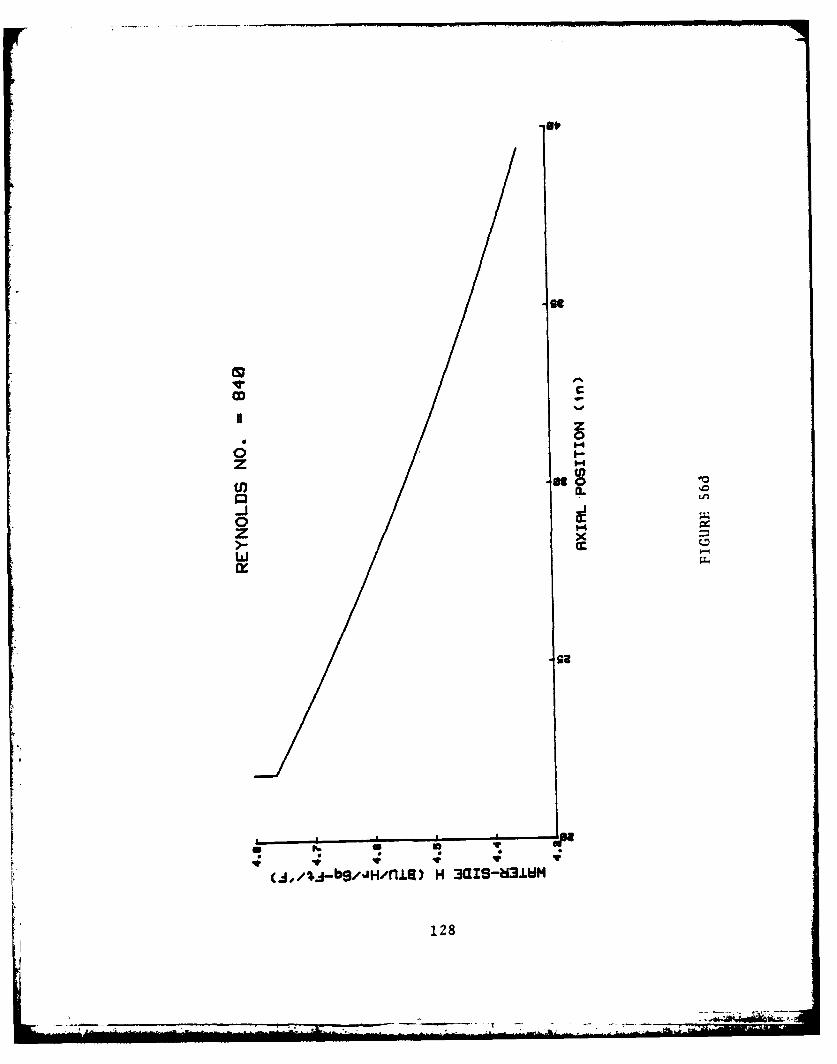
sp
CDC
z0
0 t-4o I-Z '.4
LseI
(j,/t-bS/J/nIR)H 3al0MIlW
128j
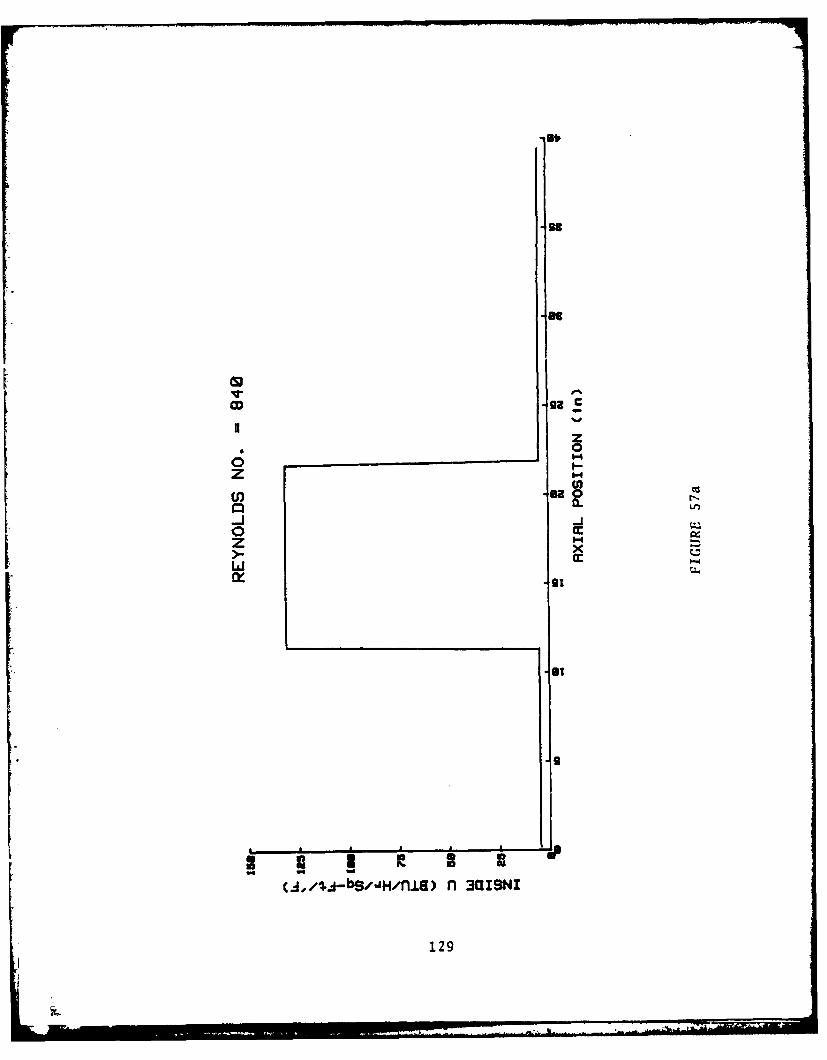
.0
uB zU0zz
CL a
00
z -x ,
w
1r BO
(.d,,i,4-bS'JH/fl±s) nl 3aISNI
129

CD:
C;t
zS
0 I-4z X.
LL'I
(j,/;.A-S/JHnlil n 3ISN
130
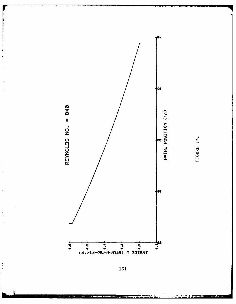
z* 0
U) u
00
z'- x
131

IS.,
UU* 00
z P-'4
-a
.i ridlzlg"
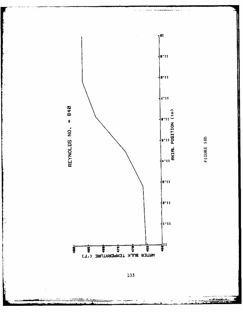
CDC
zz00
0 Cc4
z x-
(.0i
3a.W343 miaS3U
1331
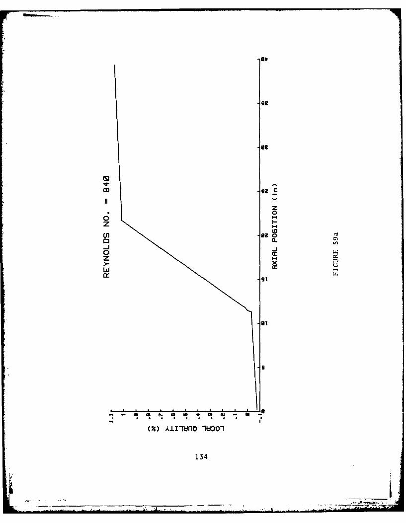
alp
CD ga C
z* 0
zU) U)
0 cc0
zLU -
cr -91 NUS
134

-CD.
zU
CLn
Ittzz
-9-
-3
in cT
135
IV. RECOMMENDATIONS FOR FURTHER RESEARCH
Investigation of the Short Straight Tube Boiler model in
this thesis was essentially the adjustments of the water/
steam mass flow rate to determine some possible operating
conditions and heat transfer characteristics. This investi-
gation was conducted upon only one tube under steady state
steady flow operation. Additionally, the model consisted of
preheat, boiling, and superheat with accompanying single
phase flow.
In order to increase the precision of the model and lead
to greater insight into the possible performance of the S.S.T.,
consideration must be given to the inclusion of two phase
heat transfer; in particular to "frothy" flow correlations.
Possible sources of this information may exist in research
and experimentation conducted in "flash-type"' water distilla-
tion systems.
Secondly, consideration should be given to apply enhanced
heat transfer configurations to the inside af the tubes;
helical wire inserts or helical vane inserts. This enhance-
ment would be required to increase the heat t-ansfer in the
preheat and superheat sections and would be very important
especially as gas temperatures decreased.
FFinally, the program should be transferred to the IBM
3033 computer in order to more efficiently process an expanded
136
program to determine actual heat exchanger size. Although a
powerful tool the HP 9845-B lacks the storage capability,
especially, disk storage, to handle a complete heat exchanger
design analysis that would be required in order to make a
reasonable comparison with other heat exchangers.
With the aforementioned analytic changes implemented, the
calculated heat transfer coefficients should be compared with
those coefficients obtained experimentally. The single tube
experiment should also include the capability for the obser-
vation of the boiling regime in order to gain possible greater
qualitative insight into the most probable flow patterns in
existence in the boiling regions within the tube.
137
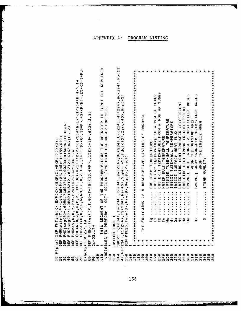
APPENDIX A: PROGRAM LISTING
i-=l
(0whi C4 N
I~7 N '41 s
0< WO W W
V' w. LL. - U -T Q'') Ix- = w W) L -W - T 4
LL' v x 0 LLW =. LL L
* -. lf 0 SOXr-: LQ '-L. mL LX :4*lL n ( r N if -t c -M cc W 'mUEJ4
.4 - n y r * a cc 9 cc xWL Q-4W-C 4'c1 'u. - *nr - r ncc OLLL.L 4'WX )w Q*c '-'') < r C ^ .#j wc N'I C Er -i w wr 40)- _ 4'"' a C ccw '-' nO CZCLxcctoW O
+ i-c co*wccn l 'Lw w o * Lw wU*- o t'T < a. n-J r x 0 w~aw.Lc -1 LL
--- Co.. \c a. *nr 0T -in w 0=aL~nwc~c =4'U) Ef)EDV 'C W E ./s "anccXixT-i -ixC ixLTnAT *
.4' *-c V U' Q)t. 0CA 0o'.l. *x -i ni-n - c co . *+ ~iaTr W a= -M =.S * E.A) EcEW .4 cEEW w *
-r W ~I- V* 4 arI' -- p LL -ILL W I SLJ w wP- P-. .V- * Iflx'- * W SW -W I C x T -i-- I-- :4'
X*fr. * K .4 i-C * > W F- W ~WLL WEZC 4' T0W I)O- .gil1 a. E5w ce- * - I-- I- 4:)Mcc W MW. Wa. *L+ 'TI - < \ - *L CA NLa 0- -1 =- m4-nl p fZD x *
-c * E-i _j. * - 4---E W Qf)~ Q 4 -) -.-C) .* > fZ z. *ZE% :4' cc =z X WWI-. _ 4 *i
CL OW W- Id * W -3A ( ) 4W W c- -w c Qc IM *z(W\N- "\ Z a4 a. w &U * W WOA) iiCO .- CW W Wx *
CL -a.CC'N- - u 0 a. - C') p T XCTCC3ZCC=x> > I\*4OD In * 11~ 'U 0 "ii- V * U L2 .--= It0 0 CU) *
OGq -+ wc 4 *1 c T
,<I-tODCOl 11 C LA-CA (0 ..................W iOiDtLa a 0 (n Y) ItLL * u....................
U ii G il:J - aL C. . . . . . . . . .
*L aQ a. a (V) zs~C
a SiXX a3 a -A 00.0 Z af-j.LsS ab - -V.- Dz W LA ?", * 0 N 3 0 V-O0 X *i- ho .114 W0s~ Q) WC(Y'TrI-- * LA. -i-- -IC m x x
wW w- - W Y CfN M- **L0 A ' S- - -- %t Y 'a T.s-(%Ir-l * U
-C-,)c .O4O0< O N md"- *f N
WzZzzzE'NJ * -- zi- **PLA.LLLLLLL C N 0 1- a- *
> MO CO -a.~ ** L.LL LA.LL.LLL. \ LL II - t ****** t * *- * *r *z
a. w ww-w 0j C A X C)* Q 4--4
138

-M LA-U
x :rT
w Q. -I .- C 0
N-L us V)-Lw T'1 PQ . L
-I I,- - _-.- ' -44 =l-c). 04 -'w W ty .- '= - 'N - IWIXI- M *L
-M z-LX:TW' i
kil -AD
Wo- *-L.. LL0 414 14
OD -it - .m T iT'-Qj 10l
f. -I o W it.A.a
Wi M i- W _j X-) l-'- '.QII o
w 0 ". -' Ci-1
n, 4= -Im a. N (1 '- w II-LI
W 4 - =' F.- - -NG
I-L. Ix FS Q A0 (14 MU -t III O' 1c40 -o toUJ' U) .= L T .
1-7 ix '- 1- 3ixI.. Z it- 1- 0 A -4i- COA..
oNF- . _j i-'s Ch dl 'i ( ai-1g If _jl.- 01 LU (0. F-' *.tF.
W C : 0 CJ M7 -- M*. XWX(EO ~XML L L -- iX .
-- -- -- W 0- X- X L( L. J LIL L( XX' AL L L n C -s,
M MZ Ma4I V V V V-(f VN WW0WWW k Df
0) i)- a~ : L.. LL0 bi~ C139a

LI C'w
x cw X IIC'
X ~~ 2-=W )U'WC) W U '. c - - Li. )
- = =3 Is Lii Q 'P04 ) n
-r U) .- 2
1 i W 'E0 - CA ) X n -4 10 It-
- A I ' aQ LJ : i -' -- a .
U. N U)J C' trs~) T Cr- I--
l-'L2It -1-'4I.1-'T-flj
CA* .. a to~l0 a. .at i.- '
4 0 - 0 0 C-' - --
C') I- Ml V)a. (nC0 X1L C...V'(h
w . a -r -r fl0 L. N ac E aPJ -i
LLt 7 tL)-0t-.(l-t~ .L U-r
0).W T..))-"' WL M..PUV-/ULLC- W L ..I...0 0 W.1 . .
-r Wx: : l C'0 l- = - m 0
-j-w 04 - wCO'1- '- IL-III- I-.1wI-c(r Ii-inQ.-- I-- P04
La. SWI-efl CLnXX-- 11.W W IO ' Xa0 T f WI' WI Z OI fl
,O-I SW~ fC) 12l-Cgo - Inxif ItO w Q W'STaw(O0-W I-4_ DW w P1- I 04 I'-X II'I M 111 'J0
Ui. a a ZIIC,.. -Zn iZ WnC')aa - Li -Cj) w Y. 0 '-I w w 4~~ .4.4 fl==I-00OJr~ O '
W 4. wa 0-3 -Zi'iL -LiI- 0.- 1411 - olaXWIA >I-DInI m 3D
=- O W 0 0 4J WlC,'. W-.J _jIn)* ( W't 00 T.3 'm P4 -c
m 4- i-oi-i-=rmzx2Zz xIn 0.0 ( l30 Z.-C0-'I04
C.'. NC'CiN'O )'s 0 1---sZ).i*-aUWt..Z~ M----- W i
K ' -\\\\ C n2 WWWWwWWWWWWWWWWWI-Cfl\ XW
-. \r.^ r artrM I.- II.- I S I I II '.
0\C'-CCCCC C.0 W X.CL0 .. U. .ILL ULL ZZ Z 0 - Z Z Z zzzz =22 2 Sf=12=ItIf Ii fil If of If Iti 1 It &i - - - - al '- - - -' ' ' 6. .6 -i
a a =l II .. CL Q(L 'A6 (L Cr Cr IM CrCr CL (r C Lr C C Cr C Lr (r Cr C (r C C 0 C Cra C
O0 0( OM0 0 M0M0 0 W0 000 D0C00 00 0 WO 00 00 0 ' 0D -N ('1 ' ' '..f OD 0%0!-C') ?r ID' W N (D000 - (M M' ' V tO ' N 0D0 (0 - CV (') 'T Ill 'O N 00 0% 0 CD Q 0 0 0D 0 0 0D (D
140
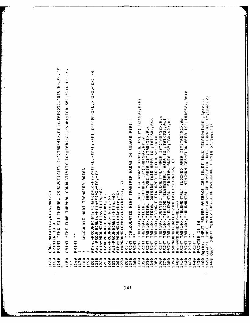
LA.
i4
Li. ~Q* I
L' li N.
-D - 0 r'-, In (n .4
10 Wfl (" 10 ) -Ii aT. it N' - - " T(0 Q
V Y y C-A .14k -M IX C& A-U11 T~ T. 10 T fr-
- 4: L I-* - - .*-* W y L
IL T .- = II.C-I) K
-~~I -l it TI) '~f'' - X Q0 + 0 l X I C - iT- 'SI CLXcc)
,Jr - W X it-inr.M.W TiW- 1-i SJ -
U- w~ fl w U-i.-I. = wLmw L ILT it -x T oxtW~ a: Ia -M 0
it xI- Cc it- T ~ ( (0 LU- I- mZ IO--f .- i :: L. .
>'.0q W I '(i Uit ~W) ix. Ta.D
*. it it IX-iIxt itr M T z0'--->x I-- m LU IX -ti0 it -M
=0 (04 X - tD CA aL : .4C CIE .4LiLX- it *- it IJ:IXLUT(0.= I.- LU =
- N- I -I I IX it T i Z-t~ X CJWT-*I- i It -- W - TLUL I U -t -0 05 (0 It(-j aT Ix * i- co :C~LZU.LC. car '0 IX - wU
= LU l i* I m ILUIIX-I= W W I- W W>T .
-x 0- I (0 .D = \ 0 I-- I.-C.- LU.4.J.4 X .4. 1- LU* C) C* \ r' *~, I.- =Z X -.. = ~ t 'Si it == j ==Cd 4 it .- '-4a.Or(CO.I. .-.t.l .. 1- II FX--
.4 i I-- *a(.i 4- Za _ Z4 -j toaC =U -- 55L(
(X M- S L M OO~ z I- Ca \0. LU I-I- -I-(0-'--M =at ' - - CLE LU L 1 4.0C\-*\O. 00. :::::J:
Cmi~~ I- '"fi4 .- l.C .4 11~r~r r ..r"' :Ixob Ix K- it (i''tii''.W kMWMMiXXXW42(KQ fl O W00 0 Q~ 0 -q L
'A. 5'0. i --- -1 -- - ' 0 -. - -

-~ ~~ ~ w ' :w -a
I- W. ON 0 QU CO r'. C C$i. S - '
b W NW Uw I - - C T - UOa. a. '-C- 'A .. if = -,')3 ) D upW a - C: 0
M Q 0U. '2I0- '9 - FCC '4) - c u- T ~*-a a
L&. Wj -a : *- 0 'ii -*: WQS (v" QC CO PO V) -C 0 -0
QW COO - C.) ~ .0'a - w w C* -W i 9 '0
-' = T -E C U) M = PQ U~L' TW'1 0 AU -n D - CC C C .1IXa J) C')- 'J= '.' M x - uQiW CC CC
a w f- W &'L u *- *CC) WL W I_ - LLS Co a x : a-s = - Q- C
a) :D Li.L W CO W. 0 ) Q%-W = = AMCO 4 WE > - = - -- to W LL
al'- LL - =- :1- - CotY LL.w AMCX - CC - C M "'j - = C LX Ix M
= W0 t W CO AM m- C0O mM XAM= IT = 4 =c = a CC TU9 C C w
- CM w '3 0 z Cm .. = 'aQLA u. 'a5 x x j) = a.- 0 f-2C W -x
0-. 0 0i1-- -- a7 -.1 *-0O) AM Cl-T X Q) Wl AM 1j = - I. x x 5
x CO (.0 1& W IllA a: -: MC CO CQ-.4. -. 'k- L.~ L .... U. J U) -' W U) S.
W 0T~I-.. 0 - 9- '-co CC " wIlCC - U0 MM CNI = 0 C) 0CWl If)II
fl - qi' x W 1- CO W C ISz CA 2 z0O - -C M l- xl~ cc 0. W - fL- -= C)CO) a & -. j Ix ') (.. - YOW r' .m
CC 0 X aW W US = =M WXMrI WL1. U) :9---t-- - to CC X .CL Ia
= = a I-.jCM w I. - C-I-- 0..C 'U:' AAM f- OW CO W C- Q- a TW C Ma AM -: 0 COl zA a CC Li.l.u AM avA A-CC U I- f-
- j I22 -- w W 1.DI- 0 0 ..J am 1COC CfOi
C O z I - - C- La. r C -0 ix wllI2- C O -
Cc .4-a > CCUC AM W =s lAM " 0 -' O IlAM CCOCOL - =51 -A LL i fi TO 9 C TT C LI- CCN) AM x -a- -WO CO 9- fiCJ -i. W 4 LL C MC CC.: .1. 0 =
C ~ ~ -4 9-Uf 0 CO COa. CA: CQ:)U 's-.
CC 0O O4 U. -.1 xIW -L 'fi Ot 45 -AM~~i l'IIZI AMI w-.S . ra 2 ae
S~ U =Wcc Z LL ~ r 'rTto k ' 55AMi - 9 MC C 1-I-'UEOaCCWIllC G ~CD CCtC0.a C IIWI
- ) CO AM: I.- wrX. - a- ---- ' :CO 1 111 = I- MZ f- l- '-.5- '-''-'llI '-':CMCC.o.j
9- 0 w wM* AM ZfC -Z ='U.1 : fl' 'U'UC= * 0. 4* ' /'.CL a. W. > WaQU =HIAW- T2 C' TC 1-C-.O. C:..
C 21 Op - 22 2 c z ^.. - ixI. -I-- I-OF f- -C C C
-j '- -c -a CL0.---L---L o U
u 0.mm~ 4=-1 .C0 .MXZOw o i- AM-'--
S 4 \-A I- I- l'-
142

0 3 3 0-
3 Q)
.0: *" . 0 0
l~tit
o U 3 3- . II .I L " I .L
- -'a t\- *II J L
3 _ Q-. 3 0.
I.- 3) 300wc CCwI&
-f I S -- =X
a. 3 U. I. -
.c v , - -- ' r 0
14v i3 "i \aC'
0 QI ,,> 3 tI C)C)O )
.... L LL,"" " I . . _ W... C * W W W
MI ua'.-3 - S x if x *- zxxxar ix apo-. bZitr ( 0.r al---Ofr( 0 - a W ( ( 3 Itllfr4F-M- 0
CW - L9. b0 -4C 1 0 i 11-i 'a If1-3 - 11o 1 - -~ ON
(A) Itr I - --- U 0. a. l- Wr ' :LCCI . f I I- C : Cs 3 #X4 CCC -t
o- If c- I I-t01 t LC)tl' Ih W- * -i -a ** ** CU * C .1 - 1 1I-'A-----v- 4 -- 00' I - uIt a- 0.-3 0 a a 0 -r a a aC
L rY 0 - rIIIC uu'00. aa3 . OGS A 3 .3 3-v3-3 3 LO ( 3l04p40b. O 0L
F WM.Ch4IzeLxQIQ-lllI3-h~~-~h(D1 Q0-9( ClI-ID -*-OhtDea0 M( D(0 W(. i m0i Z.'f0C I a CD fl-CCC3I0 0 aCCCI-I-
uSC Ii lii OaiiflO..JU.I i 14.3 Z(.I---- N t H I

p.i
FS
,-1
-, a+
m0 .1 Xzki.
X (r
3-. OQ CmII=M j .
I-- : = Z I -
Q= +1 4. ,J U -- , lip eq
-A '
a- I , I t- D :1,
, ~ ~ .T "- : Q m. X' c'- #A "0 0 .1 " - I "., U,) 0" -. I,Ca _-j X !.X M 0. .. .- 1-- "0 : - -(3 - W I-, .. j * -\ Z .=. 0
Q. -+ i-x =0 Ill; -a' M3 Wr Mr + -. L 0 '" -I X Z TO 0 1
a,. 3, C " X - 5 i* . . -1,- - i L)" CL X 11 1. 0., X v.- 3 1 a I lb :)
ex= x to Q o 0 :D U: o" I= c . . L L 00 I , to a U - . a a .., cr: . " I - ( U0 M a = .-- , . Q. a =,-0- * -3 r .1 I "-. X X ,p v -\ =
0 -" I > D' - - 3 S -. 1-- ,-,a (9, ~. 0 € -- Q llk 4I L Q. i -0 0 W QI II 4- A + I I- CQ"" = I -+ - Z 44.,I
aJ -J U. (9 A- *4 6*Ixi f1 x3 a 9 1 Qg-= : . si3. LLX i 1 a % CC -C XE ' L0 A 0t* 3 -
U_ H- OF Ch I to '<L a= Q. .- 11 G2 D ,. = -M-- 11 3w M L) 0 0 .0 ="" 0 0 0 * I M Q'+ 1\.• .l. 1 a X C & 44 1 N. 3 f= a a ,, I = -, 3 LL ,, ,, ," A 0 ,. --
(o -c 0" w0 i" ., . z C- I-- : 300 .- XQ L) ) Z W I -I " I- 1m
II (L. . 00 0: 0 ( 0 I oCC 0 .- a a., 0 II .- If II I I _1 Ia-- a-C
- '0" LLL * A00 aU.L ACh 3( U- LL -. " i. *X - a c, X -r.L
I. - = Oh U C U Q -- t C.L == h 'A- L 3 -- - - ,
SaaL I
(a Ix e4. a - -- a.o
00 3 3~v . iO I -ra'~ 3w
N C) Id N 'SI-N(4 t 9 W e nk Y I t I\ V V '2VItI 'rv~1 ItIffl.W41 1
C USC: C '-14 v on-WX .-

pr
w
It'
w4
LI
0= .4
.0 --
.iI-- Q =
-J ,. '-4)i ~ = ~
o LA o-
,j 2j --
. .- w 7
\ I\ I I v -
I-I-- I .'O,. C - ... ."
a, N D M 0 U fm 1 - Q
4 , I -IN N Q 0 0 It . C .- ,e 0 .11 0 .).
, 3 : .- , -,. f . .. 1 ^ ^- . ,,.,"..,/ ,.a 1 - , , I,- ,. '1 I ,M, ../ - i /,J .-
W ~ ~ ~ ~ ~ .' 1. 0. 3i3x003 A -)U ,
.,. + + X++ l Ch r, ,. 4p. V ap I= Q1 Q. $01 CL, kA l ,, : -0 1,- - .- ,0 4, = -- I - - ' IX = I.- v -- k-10 3 Z + + U.L e' =- X =- %/ ., ",. ,- v L .,v v i =. X lZ =- I_ w', I 1--!U 0 0 Z .3 I <. W v z (- n 0" . w M w. k 0
3 - I--.-- IC I - -D C A L - I-- 1 2. L 3
o w, to .- f a( a U 1, ) V D 0 " v a 33 L b1 -- I I (m1 M > ; A #-- Z --. , CD D 0 U u-I, U" , v2 aL I1Ca N N- A
* ZI *-- Llb ---- N -'' 4* a&ZQ 1 C4 t D 3 L A3-
i ) f' - CC I 1 I u Nt- a ( ). R -i 'Q-mN
,N I ICX Ix 0 It 0 _l 3
WZ \ 03 I 's --. C fC O l' LL.UU.LLL .LL 'A-L CC wI vL<--L - LQ( CX 3r 0.I.- ~'~ I-O1- Y CL3 a C I-a m ' ua 3 >3I ( U Q 0 *- C
N IL5\ \.a.-+
3O~rL Ol4-bt\& '.- -'- 4 04 x a f.l 'Wb-b0 I-~"Q333 43s4.A O~fl~ 4 3.03 I-'
0 iJ(D+DaaCI (D (Da -ni (DC D( D0( D(D1 D0C 000O Q '4:-1 (D(D( <-D'4D DCIN0aaI-I DZ04''nIn o l- 0 A- MI n O %Q JMI In oNO cr'-'- .Zim ~ '- N'M'a'
~ 't~3'.sr~ ~ z~z -- 145I

71, 3 3 3 Q. Q
a lia0
o. .- M 3 3 ,- 0 3-~
3-' W > A ' - 0 az 3w -A a~ .I-f 3. * Cii 3 a >a -- L L3 LI
-I-S 03 X~ '-~' u0 '- A -3 30 - -- w J)
*u u - * 4a (D do' 3( ' 3 5L l q A u vi i- '.' a 40 5 3 '- "- 3 5 ) 30- m 'A' -. 0 N (.- ..j vi u uic .Z 3 Q.C 'A A 'A '-' S O NI .- C.) ci q 3 5 %J U E .I-C 'AS3 0NLf: 'AciCA E 9t1a. J .- C'A >13 N L:2 'AA UU CiC 5114
l 3s Vit 'r 3Z=ULtaw *u.1a . St3 Cm ix LL-.lJJL _-... j.Jf- II3 0 51-1 (11.J .O3 l' .- .lI-.1- n 31 -
114

I:,I
I .
- Lk
, w = C11."'' "
i -:3 .
a -. 3 1-... k
. " MC' lip '1 '
Of Ix i
LL a j Ac
i .. 0 £ 7 o-, i ,.,
44~~- w- lp40i
0310 CL -L LL0 () I X C
,, -e - u. u = X. a. L)U. 9. , I-I- kN .0 0 W tz w "II
0 0 0 . 0CN (t b II F 1 3) (A ) o.
,a, -.- .- If, - - " 0 0 0 Of %I2
W to -I- > -xA ur
XI A* Z > 2- ) L .h- .- C L 1104
If 11 LL
L T L
L .1.L, 9 ' I It 1 1 IT al" -A u. . , 'L) 40 . ,,U ",4Y1 V 4! 4* Z If ;P ',, III if -- -. 1-- J 11 0 ZII 3 1 11, iL L = = - -I I- 1, ( cc -- QV- -It'
3 ( _S. '. "- , .I Xc 0
*w'l --- " - " *0 - -' ~ L- "' > 'W C - u -uK U. 3: a w
'.,C, 01, .l . -3. . ~i.. .4'C.--i ii I , F .. 'p- II -0 Si 0 ', 0 'C.'
-" -
. ( .)0)0 , )0, , L, e C,'3 ,, 0), , 0.0 ) CL " 0, u'C.- I- fi ¢'s 'U)~.C ca3 Qc.- 1r X (A
3. r0aj- -N 'b 3 l. ..
m* 0M s" ') -. '03.Wi- Cc MW S 0 i (y)~i ii
aa~b *rr~3'' 3(.~~' '1* "147 C

CIt 'J 'i.
il.-. I- -1,4'C4
- c ,- I. C,
= 44 ii.-
*7 .' c' I (-: ,t " 3 .k - I I X----". -- W' ".. ,- if z.. Q ,I.- -
,- CL :- I .-
+ w w 70C
- ci I
i f .- L 1 T I,-. L , i I - w , -, C X = .,- ,
i. w'. 11
,I 0 . )I W 4.-- -.- -
c I + C4$I'= a 3 a Z"i ,.- I- I- o'- . , =
-r =0 CI .- Z -J) M *- C 0ar 3 -+W1 W- 11 LL Itb'-- : C
k .I .. o1 - I-I-* I i ,-
,.- '1.._ h - U.- ' 4 :r :jd '.. .. U),",. ' h "z' 0 (J.- A'4 K' pa\ I .11.
'.j W II 0n-.1 f I kVto " = W4" W a ---
* .4' W 4' a (-'f Ir Q-a _jW
~~~~J 1I W. C ' ~ - 4 fl l + f Z
c . X W W-.. U. a.- - =. . , .
+ " 'C * ' i C0 A II---: " ( I ,"
If I ait a ^f OjIII TN : QQQQC
'3 * "4 I v- LL .a, 1-- WU I 0 W 0 . I I t r= II = I= -
X 'A i - W '-W -- P It l'- I- I . .. - a I IT Iz , I "a - .'-
-A ZrW- A\ If 1 0Q WC Cc *q -* 11 W zf- SI 0-3Z'<000WA a L)c -L) A kA ImIWW (A4 a *4C WL l I xIxi
Z (AO - -- I 4 a"., ,I 4 LL LL rI C , ,L LLCL
o 3 em I 11 i x 40 ki 11v". I ,.' = 11 L. 11 ~, I ft, OI. :X 1,1 Q1 . . - - Ir-
I'- LL. ,It 11 - 11 . 11-
41* r p(mC0c2 A I-o 44 u - 1,.--a'
L) I o c m g t o. * a it .v ,3 I Offa.a I: iiXi .0 eII II IiII ,oZ1uO ,--fII it" ''-- ' 'S -- ---------- .. " Iv,'",,.- --o XuIILaL. 0.Csds\ lt ) SLL. LL. LL LLL LL O L L .LU-I-.-- I-- -- -- ---=0 LG -L) U u a\-W hC3 Wo L ' -11 If 1 X X- XXX X X
ZI a 4f- Z -,' av '--0-- -,
Y)o £htLC C.0e a.m 0 (2u 0m
N .N Nr'N NI'N -NCO OD00)iD))0 D O D0 DCS0(%a T 0 N0 N(N()0( S
148
--- ---.- --i-- -- ---,--i- --i--,- --,,-

17 (
(1) 'LA 'u
aQ 'a'.~C 0 ' '
CL
- a: W )
.Z '.'*4 - f4 iiA
a ai
c3 - 1r ZtCL C
w
a3 a 0 0i w> - - I r
a 42- sa I= i c I- xc
_- - W W LQXt C.. w Ix r t- C
LL L u0-0-3 0 1 I SL j cO
D w1 *33 a *1-E00W -1I~~I I-wI '~C) t l 0 I U) W W
Q......c'.0.a )I(" --. 3W a1 3 =11 I XC> W QU) 's-W'ZU) 1a3'p 11 -i 1.S - (
4p .a - 41 -0 03 LL LA. W J 1 0 XiCCiiI.U0'a'(a A. SZWjf~ -"0 11 1I S '_ LU--0A,.-.-flW xT 3.3' SO s 31 LL CL. 1 ( fl3 43( iix 'x Ix IxI I-*xa L L 40OZ(a .)Qv- C3F- F- x l0 0Ix 0 a.L a (L I OI a.) =La xa
L c
0 -M 0 0m 0m . 0 00 0! (D . (D C0 0(0 0 2 0D -V 0 0D 0D -v 0 0 0D m 0 0m 0D C0 03 em 0 (D 0 (D 0nN CO as 0D - N MO 1 W) W~ r,-Z 3%,' 0 N '. 0 1? WO N 0X 0% 0 - N C' v W0'. N CC Q% 0 N 0 0% V 10
149

o x.
I- D N
-w CS a
C *l cc w 0
C- zI H C
L CC LL 1U I-
3 ~ ~ C 0 c r~:
L LU a C H H f
.. =j LrU LU .4 j
0 Z cc ' LU It LU) H
Q4 c. LU w W cc +Sx CL H cc mn U
(0 wtH L CL I - -IT LU 3Ia
xC .4 H C y CC L LL 3 L) toLU .4 Ix - CL H LU
H Xt = -. 1 lx '- ::.t CX x = LU a - - - - - - - - - -
3 > w LU hf cf H; Zfl) In3 0. 0 0 0 O 30-o_j 0 z4 H 0-lx a a i.a..aa.i. r. S 0atx .4 _j Y1) -r (I &X0 L~ZL '.3O-'0 - OO-C0'cC CC C CC.40 z 11 -L If 1, a - =Xc.Z.cc_ :cc 1 t 'I .\ W ) 0 CL II HI ZOXf~ X3Z ixL>l H xU LU c xa cr ( .. ~ :, m . .
3: LL 2 (i. C.. :. vc wc, Oh HH I HI H - 55555500 P00.1. LL LaLr X iL LLNH- CLC -L
- N -D - - - - - V -f -WQNOD % - N 0I hr :) kD r- -D - --- )VU)W D0-T -rchchh ru VV. hrrU)rCL U)InU) f)U IIr 0 0in(0hrWhDr0 ( WWN NNN NP rNN hDODCLCLCLCLVCITLCLOrCVLV . - 'Tti VrrV CLLflLLC'L ItJVU'JItIJUUUL2CtL"CLCItVLtCLCI
ISO- -- --
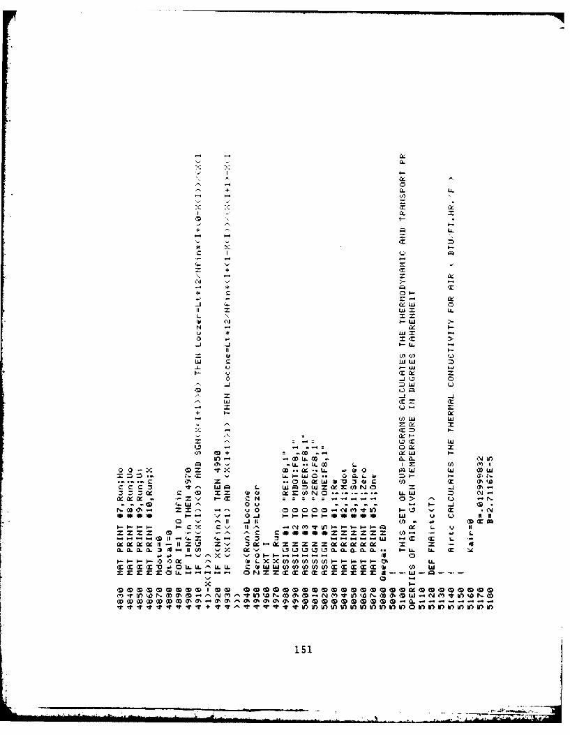
CL
CL LL
C.1 w
LL
-L u' I- -
:44 x I-
J, 0 I O C CaII F
U' OD U.O L L
z '' w 14 L '5 Q 00
3 t x= ( pI. W M Cix IX WI .LL- x
NND0 - CL 0 0 0IN V -1--0
so* -. a I0aa SQ.-. I 0) I- 0 cc
0 t- I-(EX T.M4-OU. -LL Cw ww 00 A 0(A C m C ( G (0 CD
wI '5 , U a%00000000000-CL =

LL
D +
LL. + i C
11 2 +++ .. 7)
+ --
'3 -N I +- - It A Ir -Nf. * W N J I IW I I <I IIII < k
Oa V' Ni W r 0-CNWNWUII w o v **0 toi WdNNQ0 00 0 + P
NN+ L ~ My .3>,0-WIW0)N (T IN mwI
. :I- "; *, 0) * t . .- .Fit N ~ it mu AB 0 101+ LL -' 0M It.j*
IfIf1N If + L.Jc ( taI I f I X-(C'JI aO ItNI-toC a-i Qw U i(C a -10\J ML 2 -W IW 1 Ifj IMQ WIK +
WI W N<L NCJW1JWI 0 11UNi 'AnCWN l w 1.OCJDtL W xit0I amO**cOIO VNC -x U. T 1...'. t C. CL C'x >t fN x
d~~~j.-.N~~~~')Cj+~~ L..U )-5 -0- N I 7 *D4slN.0.50.1- II 0 w.1 .. 4 I D d N.C
LL .UN0~. ' . J ;4
0 I D mkv00(D0( < DmD() D0( lw .2ii Q (D i- D DCDM OD CD 00 mj*1
IIIIIEI+ . OINININIC A C 101N115200
ceN
wwCl-4
w v?
I-CLIII
CL
La.
.4 I
I-U) La.
I-L
* w
ft UN Wf
L. .4c Ix l
1± C) OD*NI(LI t - Na
'TW I IW I- w ' 0 <4 LC) W N W +NrD* ftDLL +4V O N 0 5LJ)kD.- %( .
.-. l'..- U)N MiL U) -- ) M N to z(04 U
tW O V W) Im * . 'A Ia t-.CIDNVM1.- 0 5 UJ I * If) I M N 1 +_ -C0 l'- W) ' ' N 1O .
-i LO0CVJC'JWW+ to w *Nt t'-*- ~ = I- +jNe~r--. Sx If
S~~~ I.- Q- Q%* fi e+ I- X .= u I.- .a- C IN 0 -
ft in. Z' M. L.f = a = NC) -- r- a -) a- 3 -
(3) ow QC mD0 0 0 C C 0W SD (D o 'nI im00( (' DQCDC DOQ D00ft -7 C ) '0W9W- Oft I-ft (S C) N-' M -OW9-WMCI
La. 0 Ia La.
S S I-53
LA-
LUA
-
LU
w
w
- LU
+ -
* P*+ .0 .N
ODWVW+ -nW - NI
NN V M o * z +,N N X 0-V X
+-W) O -- 3D al -(4D - 1 M O OIr .. N *' -A w N oNto - X-CC
+l (j , W( - XW' -i +" -f 41l'
0 w4 =wc ' ji L
OLItW+ IL) 0-LUUX (L CL XU
If)UUInV) If) ' U# k' W 4Dt 10t DkOR kDMVJ'J D ADk 4 r.. k&4 %a to ko'.k o
154 -N N X C -tX

a.
LL Y
- C
T a.
W .- W?-L
u ~ 0+
o ix
0) Q L -j ILS=ill <
UU
L Zw +i wm L
'-'Eta
LU aIIu V -I W
CL , I- w LWIN V I * oV M 0 0 " ow :x4m f -a - m . is Q 4 - ().%-
flX - uL 0 L i- ( Q
CA + L I A L A
L) 4j'Lrow
o - - w
o ir0t 0e NMV0 oNM I 0%N0 '0 IN Mv0WNtoU us to W oWWWWWtoWW1 o oWW ot to Wt
C.. ~ ''.. ; ~ r hi - C.Cs
(00 0 '10--* ZIWC)'% SN W .t.

LiL
6rn
IIT
+ a C
Lu aLx 0- N -I - W
t: '4 W -W .1W 1
ol - * w IO O o~" N 1- CLuWW I+ w (0ov o w om
%0VV* 0 .- II"N(4()i 00W0 1.-
-k V . +a .. . . . .. It - 0 4 D C~
3 SN I I 0 07 9w - .D.- INI.+- 1- N
* ~ ~ ~ ~ I I.0 Iu Lu W D1 E( a I- 10 r0I WIN 1 N 9li l vt wII I I 3 ej s. 'w) 'AD U If I Ill N V " 'AD1 If 11_. i
01 PW&O 4 -A-C Lu ZC\ E I PWw C'P''AW-. Lu =,0O I I I) I- NO &NslW O I.-ON-
'P~OW:W I- = 31 u Z-C''jf' to0o00ULQ'PnNQ.0W1M-'A IL. k1P- N0A-.(CI-W T.3 IL
-~ Lu X..PISQC~o -~ wSN 0Q. C I. Q.. Q e P - Q ) . . . - ,.~
woolI II ' GOQ'OI-OM "QIGo 4GO C '-WO Co owwm
IIIIIII I I I 5 .JIQIIIIIIII'-IIIIIIII156.J 1

4w
LaL.
a +-
+ L01 - o
+l < ~ (J(
NOaMWV WWNM O MI-I
NO OW o owywo w ++4'OW W ncZ'N n If)1-
N N tr)N r-(W)qr I- 4 N~l~ wvN02~~~ ~ ~ ~ - (1 DW-r .J W oI (4( oI W oV M N Oe4D~ ~ ~ ~ oi, *o()u -v( ac i -q % v o Aw (. w
A' kal w *.0
= -*LLLa
NNNN :-
Y)C) II ()C' I C')'157

X
wU
I-
+ ~ 0+
w z
It nN () N L (
L N Lt I I--ZI
4.OON U -kN a ~ Q
w tooo w C I- aN M O 0+
IA VX '' 9()0 DM a( A-' ) V 0 '2. 4. G0()( D -t d+ r0 -V S + ko
Ls in (D -0 () ( C % -1 U) m 3 V
LL -1 ltoI -. 1 .
o w . . -Q . m k aO :u i A i a. +LMY 6Q
L- =. - - +--nL =k' LL
= 158
I-
L k
-I
---
I-- -.
'--w I
I- +
0I'~
1- 4"
OD: w %O )J DQ 13 Dq
::, I-
+: I-- f.+Z;--
I.- + OD L W TI n
I-- . V V S .DC) .(j D . .N .I D( a_
; ') G. Of - i~ 0 - ' li9 -~ (1" M N,= - ~ 1- N DN T) * -
,.1 X in a Ib I - I 0 I WO I Co (D .- I I . Iml 1 cyr I - I M Oa/ 04/ 1 M ItN N4 11/ 11 11 11 11 11 If I If +-I" W:3 if if NI 11 0f + (X tO 11 11 11 + 10 11 11 +i :3
11 11 110)t ix -. 1 'A k 'A -- 0 - OfA I-
.6 -Z" LL.- W~. ---0 4I. .- 0 lLi. .- 0 .- 3 LilJ I=
LL w
w~~ .. .. .. -
o15 9
... . . .. .. ". . . " ' - ," . . . . . . .. ... , ,..) ...... . . . ... . .* :4..1 .i -

ILL
-J LX
LI-
A.AAr w
LL
Li.I
to (DG - -
0< OD AD - - Dk
L) (v I r DU)i
(A~~~6 -M if) 02 LL Q2 em (NI20 p Q N2V >
to 0 t - u N Q~ vD W)O 0 NCtgI N(1 OD er - - ND U ') ID '30 Ni 02 0. Cm
V.I
..
-
W+ + x Nt,
"t" O rI--
< <.N
= ~ 6" w= 3
WI14111141 O o m+ll~ c, w 4.I. r- (P. W'A MA I . If N M I O O. "") , NI SI
W i2 (30 ir 10 - OD *. 0 0MM- k., -4
N - CD - 0 . . L - . Ma 0% • Q = (w) + - a v w . . 0 .*OD(d -- .' C- L I- 4 . . .- oe) ' . I-- O V11 -
I 1 04 1 N2 1 11 11 ,. T. If .NA I -' I M.' I U1 II kit (E (D O -. I - I'.If I I II if to 1 11 1 0 $ 0 z" 'AJl If U 11 11 11 I .11 '1
" " 0- X .1 11 " 11 U I t I.
I" , '- S- ,.i: C.'..- :E .
+ A W. M k
I- I -.- . ..1 -A .. ..
LA. ILL
+ +
L- Q. U. 9
W N 0 .- '- .4) V , W N , - -
:4W'wN N- *N N o OOM000 %0%C07 0
La Sr1La

X-
I4LL
1k+
+ +
ir- 4-- YjA +wr W z I N1D 0
.r+ xIt- r Dt + X0D-M+ - 0w X 3 I--o f-- 4'-N 0 0 0 1- 1- %()-I- t C JC -(* 0 L 9O n oM* O D -W M M V
N --- M .t 4- P-' +- +20 %+-' MM0( S
- f DNMC b 0 -~ 0%0-TI)V-C 0 Y. 0 (S DI
11% (A-. I-1 ( I N No 1(N I to 11 V. If* D I-P
1< Om 0.MMW ^0A'"QS'Xm0 (4) ix 7'0 4NQWw
u-A aA I a LA -A" .L0 - AII . -U
= C')4W S 1I* N.O-' >. =, N C- IN4(3~ ~~~ ~~~~~~~ LU -O'D' La-OW) N'U ~U 0 a
4+ ~ ~ ~ ~ ~ ~ ~ ~ ~ ~ L Q1)~ D 0.'+ * O ' L ',0a--
CI- 4-~~')i~- C'..~- tfQJfl I- S -tU1C62.

I.-
L
I-
LLLU ) I 'D 1 -
C") CA -D P)-0O M I) ,I 1 0 AC)I
kA -M 0 - f) - it - N
N1 IA t1)N I I 0~.f V0 Wo -r0WNO I
-IliwN wcl i -w w
NO M O - 0± WWW.- (A' IX (D'% IIf T
'S LI
Z't* W S L>' = Q-~ 3 Q-00t') ('D C ~ ttf0
NoNt0ta, 0 -C aN0 (AIC In V.17%o N 00 *it stO *" N*r0 NMC
'N, 0% 0 1%a 0 C'OS + 7 -7 01 ei- 0%0 J %0%0 0 0 0~r r ~.3 % % .*% a% r. a% C '. -0 ,11% .. .- (P% M.
ON CO *t *-- a LU 'S- ~ *- C)i~f-Ci()i~f-Nt163%If

N m I ) I(AI N I'4DII If )1N
W - W- W N I wIhJ wlIw Iw Iw IwgIw IwJI w Iw- wIwi' ir WIl v 1W' 11lo WN i.W rW10)W-WDW 4ttW'OWCD~ I OD 11) owr'- W N W0IO W OO)W 1?0Ot10'tUNO'~ O Is'N(Vn I0 'D I Q)N NWOC -V a- NnDO'')YUU1WNU''7'DNWA W)NG'NW)1
'o000'DOt 0N kD 0Cl)ACOCO0tC 100vNNNON O NtOCNO 0 0 ()N0%)N
w ) wa0 -.- C k 0% ZNN V- OD *CONI . -i .0 *OD *N W *I)N - 0% *1 D I r )
(Dit - (.% = )N 0 N. c') - N 4 ) - N C' OD - N ) - N W ) CO ITN 0) ODaN.aa 4 . an .' a (a a a(4 .. (
4V' I' U) I) U) I) X I0 -- - N Nl I ' N ' I ' V ) 1 ' - 4 ' 4 1 ' 4' I I IT) 1 ) N t 0 - - -
oAM M IL 0 0' a.
164

LI.
L-
ce0-L
w CwC-) W" OWW, W D , W LD"W, WDO -w i wn iW, W O-
-)D .3 co t 17 -4Da16- 17 ODv c M - NItW
M La.
+ w
Ci .7v Cw C') "0, U, N7 G.
W W W )uI I Y)IWkdII-rI JIW I- I1o1W^ 1 0. I-
m 1 C 'v *lWqIn In In 0fm )cW- 0 - qx if)
.- P'.D.z-U OO NCJN ),'0N''7fl OO ', x *.
UN00-- N- ,')c0 'I-N 0 - M (7~)N U, t0 Nca0N Q S i
CD IV0. ODU,. ')Q.OGC') 0 0 0 D( D(DI D( 0 WD Q
It~IUW~ hI hhIt~lhf~hI hl~fl b165

U') ,I ' 00a.
ifN (1N N7Ot N-D I-- *D - N 0011 61 I)v~ I f1- I) Ir III A a0N IwIN ID I
InIM -N X 0 O 9 -U D N()k *mO N N O W W O I% N - If l I Dl C N --
t(J0% -1 NIO11 0JN NNItt-'0t O f
r *S I-- ~ aa MUJw 'I.-
NU x x 0 eNS xaO W O 0 NtDyz N 0z - NSLfd.' V0- *00) I* *N * 0
hI * a 1 C---------------------------------------- ------
N05 .N~n O I -. NNN00)00)tt~fIAf166X
C5"C C'-.~ oxmmm m~~mmmm mmm m~-t =

Li.
I-
w
Q-Itin(
U-kj () 0
^3 QoInk l O-J V v 11c DID-
000
* *D
aa '3 9k WW (1 0 CL- tJ) . IQ
* go 0 CL) NO .C ) L) Q U.0 -oW
'3 -Q. 0-.~tQ% so 00N0167
LA.
LA.O
nj rN -w
WLWWaW WW -M i %N- A(2 O
w r0) - (
- xd (Me 3 ()1-C 0.(). (D . -C .-tNJI O1) N -No I- t DQ a -.f . (D ) -3 Ic V -- 1 W -( -11
O D(D W *1 W ~ t tDNINrINNI III IWI 1 11
w- ((flI WlUW.)D.10 IWflWNOWWIS-
S ~ i '0 I.- at ItQ 0wc N~ t D p~-~ ~~~~~~ -0- 4 5 trNOlC)'Cvc..N
La -L QQQ 05 e. w0 Mf-) G..AGx LaL4 U .S 14(
r. - ~ Z~' mQ t- . Ot O ~ fU)16-8)
LLi
LLL
w-DJ0%1w
N~u9)
If'*C "A( C 'i
If In Co coI l7IN ia I N 0 I f 1 0 0 WW0)fWN~ IA
.I.- a m. '6 L) w
0 0 w -A LA T QQOQOQQT(T)t.OQL.WOO~I 0 Q 'A Mf U N ' O C WO ) .
I--N1j -- W -
IflWU) Ia f)~C I I- I *.1I69l

-* U NO 0 OD7G'.C- I - I - . I - I N (
I~~~~ W I I W I W)O L l t ' fl - N l I* W. I aaWW NWNC-ttQ)N%.N(WSD0Nl0- I NO
ND~-Inlw~~twtNN~%Nnn< ' tNU)
t ~ ~ ~ ~ ~ ~ ~ ~ ~ g 13D OD.U .%W-Wt U V~UU M N - (.D Vl
*r~f7.1
) O % v. )~..7.eUr - W! + -Z aWQ .
-. %l.N. ).IA Q%.N. C).iD.-Nd t-11 0 ItZXWQ G-1 IN 1 flI uItVI tolI V)I N IN II I a Ii) 96 .I-. . . I
- 1 a t a a it a a a as a a as a as a a1 as as a a a1 L) to Is 's 11 IsI'Q
I- I- LU 0.Ix xtQ xgon--o WO 1 CC .
170ZA Z E
ION (m to CdIL2- 7..
i~J W W-I -WI lW 1-1 lw-IlOhICO%'OIWCIfWWWIWIWW~diWW I I--W Nd
0 4 - tq
Q.Q.tlQ(D. . ' Q %...C)0 M Q.C() C (C 10C ) C
I T 7 ; (4 '16 (Ij '1 1 1w ta r Ai - 14 I I - Io a LaIl
11 '.. It If 11 's Ns 1s 's '., Hs 's 's s 1 '.s 11 '. I 0) W) 11 0. N "4 1' s - - ' -
f- Iw
U. ZLA. UI z
171

Ofmn(
L a OL -ly 3D l N1-0 0 N f) (V)ko %j
1 C4 (n I - -0 " 1 %N -J
Nw -u NW I I O I II - I I < U I.
C-i io i, + .i
(C)
o1 1- (o+ 4?
a a L E I
. . . .. . . . . . . .. a -a . I
NW 10 W W.1 Il-Ill-SI L) I- N.It~ t tW I WW WW I a L LI in
WiSWW~fNU5Wt~wt~ttN~t- 172b

CoL
C'
CTd
IC'
1k
+ * 0
to U
ifL)•- 0 t1- .
-I .01--
k.D 1 + WC
0i N. I-. + I ILl
+ -)L Lo L-
C. a J3- is)
0.1 0 0 ,3
< *to v CaC." N .r iCa I *.',
,." LI- .' -. :t'it
Co I-- O . Wi .0 IT N
,.w kD 'L~L 1 0 w ) >~. v) - 0 ) 0 dO N0 .C D0
m.- 13) (4/x
.\ 4 * .* l I qr 0Q w J OD (Y I0/ p I- w w0 w N D w - I N 0 (Nl N. *€ ..,,.,, ( ,0, - + 04c + *- ' ,. U) In - tN. )(n(D MN" V(D O D
WD 1 0 D D M1-- IX kitP I CD CD I--0% C• w 1. ODl N£ (D G0 In C1 Nl, -".v- t. (%j N-
I \ * 1 C M * - \ ND -M I D . .
U') Tr 10 O, 0% IL CA 0% I) I4 0 (9 "I- 11 0 +3 00: vql 0 (D W 11 It 1I II II
. ~ ~ ~ t Calr W0 OD*\O W -# L - ,C D . ,,
,(%j ka (14 (v 0 -0 ) 0 *1% II -0 4"
itl 11 kI :5 nL T., N If 11 N v 11 Wv v (M,, DI'- M 1 11 A) ...
It ~ ~ d~ t1a It I f 1 1N 0 1g ,- 0 . 4 -
173
Cd. s* rl'
-L X
CID0
ck r)
0 OD k4 d a,i.. c1i
0%~~~~~~ ~ ~ ~ ~ ~ ka 10 t 0 D0I h C N CD 0 J
M ~ ~ ~ ~ ~ ~ ~ ~ ~ ~ ~ ~ ~ ~ I 0 WV O )' ' D' 0MMW()W V
. Os I' I- I I-
I- <W-' --O I- ma( 1 .
0 O%(D(D Ma D s) ) 3 'DYIOlm D0()(DWQ7( 0( sC 0 N'C L 0 'S Z 0 0)
0) OfU~lN G~l~DIi~~wn0C'tD)n * -' C' +1)04

r
:4c .
4*
,o r'-:41 LA. ,
* 0 .w
4' ='
I - :4 - 'a
- -- 4 -I I-
.- - -
tI-
-v ,. . w Q 4' ,'.
*0
419 I I - ,I " ,I - w . . .3. 4' .-
" (A, : .- ' , , I- . . ,-I- -- I- --- 4-- I- - - -- --
2. . : . . , . ,"" ,: , . ,,,- - ,,-,,,- La. W- -,,.
137
Z'~~ 4±. C' ' . .I- ' _4' *
2.2 L)'C) 'a C
I. .4 . a
'Z Zhi S *
I. x: IX *l -
I-.. 9' .. 0- .
'W -A z: 4' I- --- Xie - hi *0 11 a l --
14 L - .'4 I- If (0 3 Ifl 1o. mI Ck *w a I-C'*I-)4-1 P-l-I-I. . - ' -
m u-i -D * 0 . .a . .a
3 CA * in 'aC LL ( L( L . 0
.~~~1 '5V 0. 'AC 4z as u aas * r
o s e.j .4* 175

* . -. co - - SD J ,-' I, - -CJ f '- ef'D *
4c ir-.j rj -
3-- a LL 1 - --
• ,", T 1 ," U-). uL u-. - -.. I- .-
-c • - a -. -M * .1 T "
N _- .. r- :'r .T :1 I-- C,'
4 4 ,W T:4 N ~ -. S-4 M r .
PQ -7e- ." .j ,-71,1 "
4' ~ ~ ~ ~ - Vt' u - pi
I ,-, - r, - - - - rai It C4 a4 -Za~.1 -m a Va: ~ ' 50-* - 0) .- N, - - -D
.4 •j- L :. . ":." -\J "- - ,r'- a: -
* Z .'S-• i . : - aT T-
T . : 4- --, N 0, - M I - .- -4' 40I T' ?r T -t -m X:
04 '. Ttc n 4 N 4 ix -M* ,.01 F- '- $" m M U- _ P. - ,, ?--4' 'N 1- oo xl r I: *a -. T =-,
: ,I[ I-- "' . "-- : .- : - , - t- ;ZI (n ,- "-,1) Mr--- ,
* - U * = . ) I a , . .. - -. Q "0 '
. * -- ,.- -r" '" I- I2 '-M -T -
* ". 0) - 64 ,'J "- :3,-, ,* -
:•' . a • I, .- = .. a .. ^ -
, ,) .x ' , -: --: : : ,. . =S : - . -
:-v i.W kAD .- a W Ma -. . ., ien. -SJ "- W TV - " Q = - -
4' Q -N W~ a a M N W N% l ) P - h- a
* ,1 Q 1,- 1 -T - - M M M I-- n - aa M N Q 0 11 W .
• .1- "-. I.-. , ; - 1- I.-- I.- . = - T:-/,- x. 1 I-- m '-" ,-, 0 , -.'"
* - ------- . ,' ,: h PQ.- , ,
UL
N ,
* = . ' -- a .4 G . . . .. : i. = -a- . . :. . ..- , . -Z
LL~~, Pill. - .a- SJJ M 1M 1- I-m ~L I.C .J. . ' I : ..a: E '2. D 3-. *a Z lr:€iC H=
Si.. f) -:1- : I* a = C-~ 'S
: * -. i I- I- 1- I. --I- I- I- --I-- I-- I-- . I-- I- I.- I-- I-- I1-- ,T I -- Z- I- -I,.,,
-. -,-^ - -*'0,: N:- S..-l -tO N:- - 1- 10 'S ) .- - -5 j: --.rm- .- -.--
,.* ":' Q.,.
'- ,." CL - -"L -0- I C.. LX. Ch, L , 06 N',' ( . N ,' a. . a .. 0.. aI.I V l,. a. a . P'Q1 LL LL
r.- W)) a aN
in- D ! Q0wOD-00Q( 0WCD PQ NW'S'SS0-W' vMt(D D CC (S . ( 0 H -M
V W)- ND N'. OD . '.7%J T-- 0 ' PQ - M D N I M IV I , IX DW 0k] O dM I I-- If) k N O Dv -. 'D,'D ONI'. -M
V 4 V' T V- "t V1- T0 iU)n) ni)n) nwfl)-WCM 0WC rP 0N N C . - 1,0 W W 5N
r-* ' ," " It VL r ' n -: ,- V .,., : -. -- I-- H: H- M-V- ,. .,-V ac- --V ', W a V
* ~~~~ Tjura T.aw .- - - - -aJ& ,, - Nw
176
* £1S0(lCJ :: NSf.-.J aS OI NN.4...r.OJ NSS C4.
..... . " .. . ' "r:' -Iaa aIII ~aa a a - " a: a: a: .... a a ....... a a a ain "* ~ ~ ~ ~ ~ ~ ~ ~ ~ I iN -llr ' ' %ll%/ \' ~' a a a' N'SCN' - ~.

- IN
-D r r(of1p0 k -1 Q - - Z
V - -
. - = - fl XalW w 4 - k9
U) 134 .
D _N .- - X N A
_j W 0 0 v - 4 -M
LX : ' i - M I- - X
0 0 * N a * - -W
. . .7 . . . . -
mo om o M- -0 M I--* a * -0 a '7 - C.
- - - - *-. - ri z'.JT% T ~ ox T7 * Cr ac X =3 -
7%'7~ ~~~ '7w.i- N.
- - -- ----
x- m .x'7 Ix ' ocY m xN K XQLL(LOLL' C I - 0. C-( LLLw I
r~~rzz~ -M- -n ~ ~ ~ I Q)~a' .sa
I flO'AS -a77
LIST OF REFERENCES
1. Babcock and Wilcox Co., Steam, Its Generation and Use,Babcock a.zd Wilcox Co., New York, 1963.
2. Shields, Carl D., Boilers: Types, Characteristics, andFunctions, F.W. Dodge Corporation, New York, 1961.
3. Latham, Robert F., Introduction to Marine Engineering,U.S. Naval Institute, Anapolis, Maryland, 1955.
4. Croft, Terrel, Steam Boilers, McGraw-Hill Book Co., Inc.New York, 1937.
5. Fryling, Glenn R., Combustion Engineering, CombustionEngineering Co., Inc. New York, 1966.
6. Principles of Naval Engineering, 3rd ed., NAVPERS10788-B, p. 255, Training Publications Division, NavalPersonnel Program Support Activity, Washinton, DC, 1970.
7. Combs, R.M., LCDR, U.S.N., Waste Heat Recovery UnitDesign for Gas Turbine Propulsion Systems, M.S. Thesis,Naval Postgraduate School, Monterey, California, 1979.
8. Egusa, Tatsuo, Short Straight Tube Boiler - S.S.T.,Lectures presented at Naval Postgraduate School, Monte-rey, California, 23-27 June 1980.
9. Holland, F.A., Moores, R.M., Watson, F.A., and Wilkinson,J.K., Heat Transfer, American Elsevier Publishing Co.,Inc., New York, 1970.
10. Holman, J.P., Heat Transfer, 4th ed., McGraw-Hill BookCo., Inc., New York, 1976.
11. Kays, W.M. and London, A.L., Compact Heat Exchangers,McGraw-Hill Book Co., Inc., New York, 1964.
12. Weierman, C., Taborek, J., and Marner, W.J., Comparisonof In-Line and Staggered Banks of Tubes with SegmentedFins, paper presented at the 15th National Heat Trans-fer Conference, AIChE-ASME, San Francisco, California,i9"5.
Skert. E.R.G., and Drake, R.M., AnalZsis of Heat and,.: rjnqfer, VzGraw-Hill Book Co., New York, 1972
A

14. Jakob, M., Heat Transfer and Flow Resistance in CrossFlow of Gases over Tube Banks, Trans. ASMR, vol. 60,p. 384, 1938.
15. Collier, J.G., Convective Boiling and Condensation,McGraw-Hill Book Co., New York, 1972.
16. Sieder, E.N., and Tate, C.E., Heat Transfer and PressureDrop of Liquids in Tubes, Inc. Eng. Chem., vol. 28,p. 1429, 1936.
17. Dittus, F.W., and Boelter, L.N.K., Heat Transfer in Auto-mobile Radiators of Tubular Type, Publications inEngineering, University of California, p. 443, 1930.
18. Bergles, A.E., and Rohsenow, W.M., The Determination ofForced Convection Surface-Boiling Heat Transfer, J. HeatTrans. vol. 86, pp. 365-372, 1964.
19. Hsu, Y.Y., On the Size Range of Active Nucleation Cavitieson a Heating Surface, J. Heat Trans., 843(3), pp. 207-216,1962.
20. Han, C.Y., and Griffith, P., The Mechanism of Heat Trans-fer in Nucleate Pool Boiling, Part I, Bubble InitiationGrowth and Departure, Int. J. Heat Mass Trans. 8(6),pp. 887-904, 1965.
21. Rohsenow, W.M., A Method of Correlating Heat TransferData for Surface Boiling of Liquids, Trans., ASME, 74,p. 969, 1952.
22. Rohsenow, W.M., Heat Transfer with Evaporation, Universityof Michigan Press, p. 101-150, 1953.
23. Sucec, J., Heat Transfer, Simon and Schuster TechnicalOutline, Simon and Schuster, Inc., New York, 1975.
24. Hsu, Y.Y., and Graham, R.W., Transport Processes inBoiling and Two-Phase Systems, McGraw-Hill Book Co.,New York, 1976.
25. Rohsenow, W.M., and Harnett, J/P., Editors, Handbook ofHeat Transfer, McGraw-Hill Book Co., New York, 1973.
26. Levy, S., Forced Convection Sbucooled Boiling-Predictionof Vapor Volumetric Fraction, Int. J. Heat Mass Trans.,10, pp. 951-965, 1967.
27. Tong, L.S., Boiling Heat Transfer and Two-Phase Flow,John Wiley and Sons, Inc., New York, 1965.
179

28. Chen, J. A Correlation for Boiling Heat Transfer toSaturated Fluid's in Convective Flow, ASME, 63-HT-34, 1963.
29. Afimiwala, K.A., Interactive Computer Methods for DesignOptimization, Ph.D. Thesis. State University of New York,BuiititalNew York, 1976.
180
INITIAL DISTRIBUTION LIST
No. Copies
1. Defense Technical Information Center 2Cameron StationAlexandria, Virginia 22314
2. Library, Code 0142 2Naval Postgraduate SchoolMonterey, California 93940
3. Department Chairman, Code 69 2Department of Mechanical EngineeringNaval Postgraduate SchoolMonterey, California 39340
4. Professor Paul F. Pucci, Code 69Pc 3Department of Mechanical Engineering iNaval Postgraduate School
Monterey, California 93940
S. Professor Jack Stodghill 1IIDept. of MathematicsDickenson CollegeCarlisle, Pennsylvania 17013
6. Lt. Leo W. Vollmer, Jr.1Rural Route $4Vincennes, Indiana 47591
181