Embed Size (px)
Citation preview
N Committed to Nuclear Excellence
Prairie lsland Nuclear Generating Plant Operated by Nuclear Management Company, LLC
U S Nuclear Regulatory Commission ATTN: Document Control Desk Washington, DC 20555-0001
Prairie lsland Nuclear Generating Plant Unit 2 Docket 50-306 License No. DPR-60
Core Operating Limits Report (COLR) for Prairie lsland Unit 2 Cvcle 24, Revision 1
Pursuant to the requirements of Technical Specification 5.6.5.d1 the COLR for Prairie lsland Nuclear Generating Plant Unit 2, Cycle 24, Revision 1 is attached. The limits specified in the attached COLR have been established using Nuclear Regulatory Commission (NRC) approved methodologies.
The Unit 2 COLR has been revised for Cycle 24, Modes 1 - 6, to incorporate the following changes:
Revised Section 3.2.1 to state the W(Z) values and F ~ ~ ( z ) Penalty Factors are provided in Tables 2 and 3. Revised the Reference section to correct a minor typographical error in reference #24, WCAP-16009-P-A, "Realistic Large-Break LOCA Evaluation Methodology Using the Automated Statistical Treatment of Uncertainty Method (ASTRUM)," March 2005. The reference previously stated "Marck 2005" versus "March 2005". Deleted reference #26 since this was only applicable for Cycle 24 COLR, Revision 0. Revised Table 1 to include values for Modes 1 through 6. Added Table 2, W(Z) Values, and Table 3, F ~ ~ ( z ) Penalty Factor.
1717 Wakonade Drive East Welch, Minnesota 55089-9642 Telephone: 651.388.1 121

Document Control Desk Page 2
Summary of Commitments
This letter contains no new commitments and no revisions to existing commitments.
~ h o m a s J. Palmisano Site Vice President, Prairie Island Nuclear Generating Plant Nuclear Management Company, LLC
Enclosure (1 )
cc: Administrator, Region Ill, USNRC Project Manager, Prairie Island, USNRC Resident Inspector, Prairie Island, USNRC
ENCLOSURE 1
PRAIRIE ISLAND NUCLEAR GENERATING PLANT CORE OPERATING LIMITS REPORT
UNIT 2 - CYCLE 24 REVISION 1
16 pages follow

Core Operating Limits Report Unit 2, Cycle 24
Revision 1
PRAIRIE ISLAND NUCLEAR GENERATING PLANT
CORE OPERATING LIMITS REPORT
UNIT 2 - CYCLE 24
REVISION 1
Reviewed By: Am> ~ate:-
Supervisor, NSSS
Date: (L/ 4 /0 b Supervisor, PWR Analyses
Approved By: @ Date: l c ~ ' ~ o ' MikeC lson Director, Site Engineering
Note: This report is not part of the Technical Specifications
This report is referenced in the Technical Specifications
Page 1 of 16
Core Operating Limits Report Unit 2, Cycle 24
Revision 1
PRAIRIE ISLAND NUCLEAR GENERATING PLANT
CORE OPERATING LIMITS REPORT
UNIT 2 - CYCLE 24
REVISION 1
This report provides the values of the limits for Unit 2 Cycle 24 as required by Technical Specification Section 5.6.5. These values have been established using NRC approved methodology and are established such that all applicable limits of the plant safety analysis are met. The Technical Specifications affected by this report are listed below:
Reactor Core SLs Shutdown Margin (SDM) Isothermal Temperature Coefficient (ITC) Shutdown Bank Insertion Limits Control Bank Insertion Limits Physics Tests Exceptions - MODE 2 Heat Flux Hot Channel Factor (FQ(z)) Nuclear Enthalpy Rise Hot Channel Factor (F& ) Axial Flux Difference (AFD) Reactor Trip System (RTS) Instrumentation Overtemperature AT and Overpower AT Parameter Values for Table 3.3.1 - 1 RCS Pressure, Temperature, and Flow - Departure from Nucleate Boiling (DNB) Limits Boron Concentration
1. 2.1.1 Reactor Core Safety Limits
Reactor Core Safety Limits are shown in Figure 1.
Reference Technical Specification section 2.1.1.
2. 3.1.1 Shutdown Margin Requirements Minimum Shutdown Margin requirements are shown in Table 1.
Reference Technical Specification section 3.1.1
Page 2 of 16

Core Operating Limits Report Unit 2, Cycle 24
Revision 1
3. 3.1.3 Isothermal Temperature Coefficient (ITC) ITC Upper limit:
a. < 5 pcrnI0F for power levels < 70% RTP; and b. less than a line which slopes linearly from
i) 0 pcmPF at power level = 70% RTP to ii) - 1 .SpcrnPF at power level = 100% RTP
ITC Lower limit: a. -32.7 pcm/"F
Reference Technical Specification section 3.1.3.
4. 3.1.5 Shutdown Bank Insertion Limits
The shutdown rods shall be fully withdrawn.
Reference Technical Specification section 3.1.5.
5. 3.1.6 Control Bank Insertion Limits
The control rod banks shall be limited in physical insertion as shown in Figures 2, 3, and 4.
The control rod banks withdrawal sequence shall be Bank A, Bank B, Bank C, and finally Bank D.
The control rod banks shall be withdrawn maintaining 128 step tip-to-tip distance.
Reference Technical Specification section 3.1.6.
6. 3.1.8 Physics Tests Exceptions - MODE 2
Minimum Shutdown Margin requirements during physics testing are shown in Table 1.
Reference Technical Specification section 3.1.8.

Core Operating Limits Report Unit 2, Cycle 24
Revision 1
7. 3.2.1 Heat Flux Hot Channel Factor ( F Q a
The Heat Flux Hot Channel Factor shall be within the following limits:
CFQ = 2.50
K(Z) is a constant value = 1.0 at all elevations.
W(Z) values are provided in Table 2.
F ~ ~ ( z ) Penalty Factors are provided in Table 3.
Applicability: MODE 1.
Reference Technical Specification section 3.2.1
8. 3.2.2 Nuclear Enthalvv Rise Hot Channel Factor (F~AH
The Nuclear Enthalpy Rise Hot Channel Factor shall be within the following limit:
Fm I 1.77 x [ l + 0.3(1- P)]
where: P is the fraction of RATED THERMAL POWER at which
the core is operating.
Applicability: MODE I.
Reference Technical Specification section 3.2.2
9. 3.2.3 Axial Flux Difference (AFD)
The indicated axial flux difference, in % flux difference units, shall be maintained within
the allowed operational space defined by Figure 5.
Applicability: MODE 1 with RATED THERMAL POWER 2 50% RTP.
Reference Technical Specification sections 3.2.3.
Page 4 of 16
Core Operating Limits Report Unit 2, Cycle 24
Revision 1
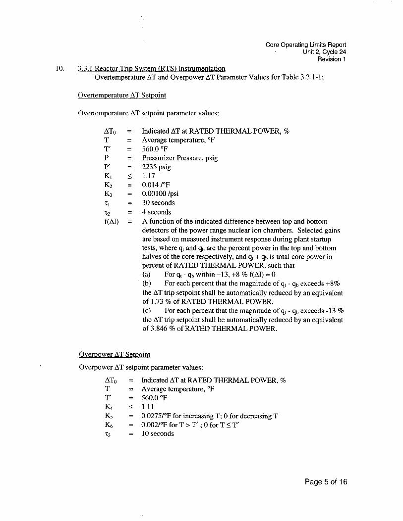
10. 3.3.1 Reactor Trip System (RTS) Instrumentation Overtemperature AT and Overpower AT Parameter Values for Table 3.3.1-1;
Overtemperature AT Setpoint
Overtemperature AT setpoint parameter values:
ATo = Indicated AT at RATED THERMAL POWER, % Average temperature, OF 560.0 OF Pressurizer Pressure, psig 2235 psig 1.17 0.014 1°F 0.00100 /psi 30 seconds
x2 = 4 seconds f(A1) = A function of the indicated difference between top and bottom
detectors of the power range nuclear ion chambers. Selected gains are based on measured instrument response during plant startup tests, where q, and qb are the percent power in the top and bottom halves of the core respectively, and qt + qb is total core power in percent of RATED THERMAL POWER, such that (a) For qt - qb within -1 3, +8 % f(AI) = 0 (b) For each percent that the magnitude of qt - qb exceeds +8% the AT trip setpoint shall be automatically reduced by an equivalent of 1.73 % of RATED THERMAL POWER. (c) For each percent that the magnitude of q, - qb exceeds - 13 % the AT trip setpoint shall be automatically reduced by an equivalent of 3.846 % of RATED THERMAL POWER.
Overpower AT Setvoint
Overpower AT setpoint parameter values:
AT0 = Indicated AT at RATED THERMAL POWER, % T = Average temperature, OF T' = 560.0 OF Kq 5 1.11 K5 = 0.0275I0F for increasing T; 0 for decreasing T & = 0.002I0F for T > T' ; 0 for T I T' 7 3 = 10 seconds

Core Operating Limits Report Unit 2, Cycle 24
Revision 1
1 1. 3.4.1 RCS Pressure, Temperature, and Flow - Departure from Nucleate Boiling (DNB) Limits -
I'ressurizer pressure limit = 2205 psia RCS average temperature limit = 564OF RCS total flow rate limit = 178,000 gpm
Reference Technical Specification section 3.4.1.
12. 3.9.1 Refueling Boron Concentration.
The boron concentration of the reactor coolant system and the refueling cavity shall be sufficient to ensure that the more restrictive of the following conditions is met: a) Kff 10.95 b) :!000 ppm c) 'The Shutdown Margin specified in Table 1
Reference Technical Specification section 3.9.1.

Core Operating Limits Report Unit 2, Cycle 24
Revision 1
REFERENCES
NSPNAD-8101-A, "Qualification of Reactor Physics Methods for Application to Prairie Island," Revision 2, October 2000.
NSPNAD-8102-PA, "Prairie Island Nuclear Power Plant Reload Safety Evaluation Method,s for Application to PI Units," Revision 7, July 1999.
NSPNA.D-97002-PA, "Northern States Power Company's "Steam Line Break Methodology," Revision 1, October 2000.
WCAP-9272-P-A, "Westinghouse Reload Safety Evaluation Methodology," July, 1985.
WCAP-,10054-P-A, "Westinghouse Small Break ECCS Evaluation Model using the NOTRIJMP Code," August, 1985.
WCAP-,10054-P-A, "Westinghouse Small Break ECCS Evaluation Model using the NOTRIJMP Code," Addendum 2 Revision 1, July 1997.
WCAP--10924-P-A, "Westinghouse Large Break LOCA Best Estimate Methodology," Revision 1, Volume 1 Addendum 1,2,3, December 1988.
WCAP--10924-P-A, "Westinghouse Large Break LOCA Best Estimate Methodology," Revision 2 , Volume 2 Addendum 1, December 1988.
WCAP-10924-P-A, "Westinghouse Large Break LOCA Best Estimate Methodology," Revision 1, Volume 1 Addendum 4, March 199 1.
XN-NF-77-57-(A), XN-NF-77-57, Supplement 1 (A), "Exxon Nuclear Power Distribution Control for Pressurized Water Reactors Phase 11," May 198 1.
WCAP.-13677-P-A, "10 CFR 50.46 Evaluation Model Report: W-COBRMRAC 2-Loop Upper Plenum Injection Model Update to Support z I R L o ~ ~ Cladding Options," Februaly 1994.
NSPNAD-93003-A, "Prairie Island Units 1 and 2 Transient Power Distribution Methoclology," Revision 0, April 1993.
WCAP-10216-P-A, Revision lA, "Relaxation of Constant Axial Offset Control/ FQ Surveillance Technical Specification," February 1994.
WCAP-8745-P-A, "Design Bases for the Thermal Overpower AT and Thermal Overternperature AT Trip Functions," September 1986.
WCAP-11397-P-A, "Revised Thermal Design Procedure," April 1989.

Core Operating Limits Report Unit 2, Cycle 24
Revision 1
WCAP- 14483-A, "Generic Methodology for Expanded Core Operating Limits Report," January 1999.
WCAP-'7588 Rev. 1-A, "An Evaluation of the Rod Ejection Accident in Westinghouse Pressurized Water Reactors Using Spatial Kinetics Methods," January 1975.
WCAP-7908-A, "FACTRAN - A FORTRAN IV Code for Thermal Transients in a UO:! Fuel Rod," December 1989.
WCAP-'7907-P-A, "LOFTRAN Code Description," April 1984.
WCAP-7979-P-A, "TWINKLE - A Multidimensional Neutron Kinetics Computer Code," January 1975.
WCAP-10965-P-A, "ANC: A Westinghouse Advanced Nodal Computer Code," December 1985.
WCAP-11394-P-A, "Methodology for the Analysis of the Dropped Rod Event," January 1990.
WCAP- 11596-P-A, "Qualification of the PHOENIX-P/ANC Nuclear Design System for Pressurized Water Reactor Cores," June 1988.
WCAP- 12910 Rev. 1 -A, "Pressurizer Safety Valve Set Pressure Shift," May 1993.
WCAP- 14565-P-A, "VIPRE-01 Modeling and Qualification for Pressurized Water Reactor Non-LOCA Thermal-Hydraulic Safety Analysis," October 1999.
WCAP-,14882-P-A, "RETRAN-02 Modeling and Qualification for Westinghouse Pressuri.zed Water Reactor Non-LOCA Safety Analyses," April 1999.
WCAP--16009-P-A, "Realistic Large-Break LOCA Evaluation Methodology Using the Automated Statistical Treatment of Uncertainty Method (ASTRUM)," March 2005.
50.59 Evaluation 1055, "Unit 2 Cycle 24 Core Reload."
Page 8 of 16

Core Operating Limits Report Unit 2, Cycle 24
Revision 1
Table 1
Minimum Required Shutdown Margin
I Mode 1 * I -
Plant Conditions Number of 0-1 Pump
I Mode 5***, TaVe~20OoF I 2.5%
Mode 2*
Mode 3, Tave ? 520°F Mode 3,35OoF 5 T,,, < 520°F Mode 4
2.0% 2.0% 2.0% 2.0%
I Physics Testing in Mode 2 I 0.5% Operational Mode Definitions, as per TS Table
Mode 6, ARI***, T,,, 3 68°F Mode 6, ARO***, Tav, > 68°F
* For Mode 1 and Mode 2 with Keff 2 1 .O, the minimum shutdown margin requirements are provided by the Rod Insertion Limits.
5.129%
** Charging pump(s) in service only pertains to steady state operations. It does not include transito~y operations. For example, operations such as starting a second charging pump in order to secure the operating pump would fall under the one pump in service column.
k 5.129%
*** These v,alues are also applicable for the Unit 2 Cycle 23 end of cycle.
Page 9 of 16

Core Operating Limits Report Unit 2, Cycle 24
Revision 1
Table 2 - W(z) Values(Top 10% and Bottom 8% excluded)
Page 10 of 16

Core Operating Limits Report Unit 2, Cycle 24
Revision 1
Table 3
F ~ ~ ( z ) Penalty Factor
F ~ ~ ( z ) = 1.020 for all burnups except those listed above. Linear interpolation is adequate for intermediate cycle burnups.
Cycle Burnup (MWDMTU) 0
12983 13134 13285 13436 13587 13738 13889 14040 14191 14342 14493 14644 14795 14946
Page 11 of 16
FWo(z) Penalty Factor 1.020 1.020 1.021 1.028 1.03 1 1.029 1.029 1.028 1.027 1.025 1.024 1.022 1.02 1 1.021 1.020

Core Operating Limits Report Unit 2, Cycle 24
Revision 1
Figure 1
Reactor Core Safety Limits
0 0.2 0.4 0.6 0.8 1 1.2 1.4
Fraction of Rated Thermal Power
Page 1 2 of 16

Core Operating Limits Report Unit 2, Cycle 24
Revision 1
Figure 2 Rod Insertion Limit, 128 Step Tip-to-Tip
Bank Positions Given By:
Bank C = (150 I 63) * (P - 100) + 185 + 128
NOTE: The top of the active fuel height corresponds to 224 steps. The ARO parking position may be any position above 224 steps.
Page 13 of 16

Core Operating Limits Report Unit 2, Cycle 24
Revision 1
Figure 3 Rod Insertion Limit, 128 Step Tip-to-Tip, One Bottomed Rod
(Technical Specification 3.1.4 Condition B)
Power Level, % of Rated Thermal Power
Bank Positions Given By:
Bank D = (150 / 63) * (P - 90) + 224
Bank C = (150 / 63) * (P - 90) + 224 + 128
NOTE: The top of the active fuel height corresponds to 224 steps. The ARO parking position may be any position above 224 steps.
Page 14 of 16

Core Operating Limits Report Unit 2, Cycle 24
Revision 1
Figure 4 Rod Insertion Limit, 128 Step Tip-to-Tip, One Inoperable Rod
(Technical Specification 3.1.4 Condition A)
Power Level, % of Rated Thermal Power
Bank Positions Given By:
NOTE: The top of the active fuel height corresponds to 224 steps. The ARO parking position may be any position above 224 steps.
Page 15 of 16

Core Operating Limits Report Unit 2, Cycle 24
Revision 1
Figure 5 Flux Difference Operating Envelope
Page 16 of 16