Embed Size (px)
DESCRIPTION
N-bit Comparatorn in vhdl
Citation preview

Iterative Circuit for an N-Bit Comparator Mark Hughes
ECE 590-Hardware Description Languages April 24, 2006 Homework #1
M. Hughes-N Bit Comparator 1

Objective: Create a two input N-bit comparator. The comparator should be capable of comparing two input vectors of a variable length by means of the iterative circuit approach. Specification: The comparator under design accepts two input vectors of length specified by the user. Design compares the two vectors. The result of the function is observed on the output nodes “A < B,” “A + B” and “A > B.”
N-Bit Comparator
NN
A B
A<B
A=B
A>B
Figure 1: N-Bit Comparator Theory of Operations: The system compares the two bits (A and B) and deciphers what the relation is between the pair. If A is greater than B, the “A>B” output is driven high while the others are driven low. Only one output can be asserted high at a time. Therefore, the output is coded in one-hot form.
Condition: (A>B, A=B, A<B) State: A<B 001 S1 A=B 010 S2 A>B 100 S3
The design begins with the most significant bits of the two vectors of length “N” and deciphers the relation. The outputs of each component are cascaded into the next component, which deciphers the relation for the second most significant bits. The results ripple through the design until the last component completes its evaluation. The last component’s outputs are the final outputs for the system.
M. Hughes-N Bit Comparator 2
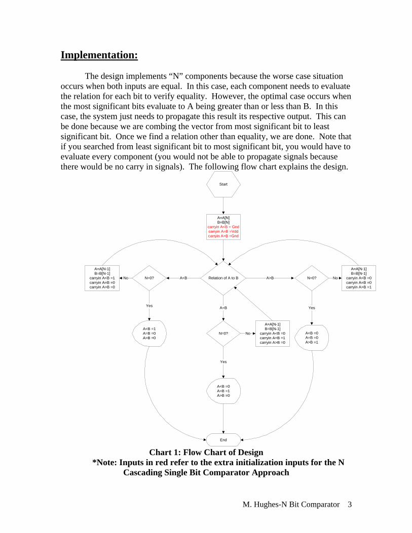
Implementation: The design implements “N” components because the worse case situation
occurs when both inputs are equal. In this case, each component needs to evaluate the relation for each bit to verify equality. However, the optimal case occurs when the most significant bits evaluate to A being greater than or less than B. In this case, the system just needs to propagate this result its respective output. This can be done because we are combing the vector from most significant bit to least significant bit. Once we find a relation other than equality, we are done. Note that if you searched from least significant bit to most significant bit, you would have to evaluate every component (you would not be able to propagate signals because there would be no carry in signals). The following flow chart explains the design.
A=A[N]B=B[N]
carryin A<B = Gndcarryin A=B =Vddcarryin A>B =Gnd
Start
Relation of A to BN=0?
A<B =1A=B =0A>B =0
A<B
Yes
A=A[N-1]B=B[N-1]
carryin A<B =1carryin A=B =0carryin A>B =0
N=0?
A<B =0A=B =0A>B =1
A>B
Yes
A=A[N-1]B=B[N-1]
carryin A<B =0carryin A=B =0carryin A>B =1
N=0?
A=B
A=A[N-1]B=B[N-1]
carryin A<B =0carryin A=B =1carryin A>B =0
No
No No
A<B =0A=B =1A>B =0
Yes
End
Chart 1: Flow Chart of Design *Note: Inputs in red refer to the extra initialization inputs for the N
Cascading Single Bit Comparator Approach
M. Hughes-N Bit Comparator 3
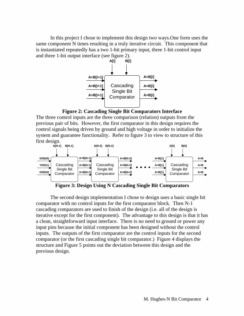
In this project I chose to implement this design two ways.One form uses the
same component N times resulting in a truly iterative circuit. This component that is instantiated repeatedly has a two 1-bit primary input, three 1-bit control input and three 1-bit output interface (see figure 2).
CascadingSingle Bit
Comparator
A[i] B[i]
A<B[i+1] A<B[i]
A>B[i+1] A>B[i]
A=B[i]A=B[i+1]
Figure 2: Cascading Single Bit Comparators Interface
The three control inputs are the three comparison (relation) outputs from the previous pair of bits. However, the first comparator in this design requires the control signals being driven by ground and high voltage in order to initialize the system and guarantee functionality. Refer to figure 3 to view to structure of this first design.
CascadingSingle Bit
Comparator
A[N-1] B[N-1]
CascadingSingle Bit
Comparator
A[N-2] B[N-2]
GND(0) A<B[N-1] A<B[N-2]
GND(0) A>B[N-1] A>B[N-2]
A=B[N-2]A=B[N-1]VDD(1) CascadingSingle Bit
Comparator
A[0] B[0]
A<B[1]
A>B[1]
A=B[1]
A<B
A>B
A=B
Figure 3: Design Using N Cascading Single Bit Comparators
The second design implementation I chose to design uses a basic single bit comparator with no control inputs for the first comparator block. Then N-1 cascading comparators are used to finish of the design (i.e. all of the design is iterative except for the first component). The advantage to this design is that it has a clean, straightforward input interface. There is no need to ground or power any input pins because the initial component has been designed without the control inputs. The outputs of the first comparator are the control inputs for the second comparator (or the first cascading single bit comparator.) Figure 4 displays the structure and Figure 5 points out the deviation between this design and the previous design.
M. Hughes-N Bit Comparator 4

Single BitComparator
A[N-1] B[N-1]
CascadingSingle Bit
Comparator
A[N-2] B[N-2]
A<B[N-1] A<B[N-2]
A>B[N-1] A>B[N-2]
A=B[N-2]A=B[N-1] CascadingSingle Bit
Comparator
A[0] B[0]
A<B[1]
A>B[1]
A=B[1]
A<B
A>B
A=B
Figure 4: Design Using Single Bit Comparator and N-1 Cascading Single Bit
Comparators
Single BitComparator
A[N-1] B[N-1]
CascadingSingle Bit
Comparator
A[N-2] B[N-2]
A<B[N-1] A<B[N-2]
A>B[N-1] A>B[N-2]
A=B[N-2]A=B[N-1]
No Cascade inputs because theN-1 index comparison is the first
comparison executed.Therefore, there are no inputscarrying in the relation of the
previous pair of bits.
Single BitComparator
A[N-1] B[N-1]
CascadingSingle Bit
Comparator
A[N-2] B[N-2]
CascadingSingle Bit
Comparator
A[N-3] B[N-3]
A<B[N-1] A<B[N-2] A<B[N-3]
A>B[N-1] A>B[N-2] A>B[N-3]
A=B[N-3]A=B[N-2]A=B[N-1]
From index N-2 to 0, thecascaded inputs are carrying inthe relation of the previous pair
of bits. Figure 5: Single Bit Comparator/N-1 Cascading Single Bit Comparator
Design Interface The completely iterative design is composed completely of the cascading
single bit comparator. In order to analyze the combinational design needed for this component, the following state diagram was developed.
Input Pattern Architecture
Bit: 4(MSB) 3 2 1 0
M. Hughes-N Bit Comparator 5
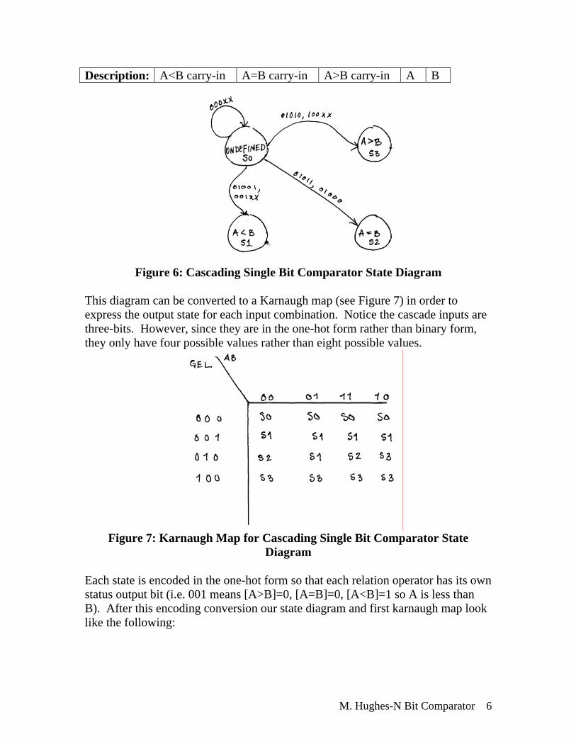
Description: A<B carry-in A=B carry-in A>B carry-in A B
Figure 6: Cascading Single Bit Comparator State Diagram
This diagram can be converted to a Karnaugh map (see Figure 7) in order to express the output state for each input combination. Notice the cascade inputs are three-bits. However, since they are in the one-hot form rather than binary form, they only have four possible values rather than eight possible values.
Figure 7: Karnaugh Map for Cascading Single Bit Comparator State
Diagram
Each state is encoded in the one-hot form so that each relation operator has its own status output bit (i.e. 001 means [A>B]=0, [A=B]=0, [A<B]=1 so A is less than B). After this encoding conversion our state diagram and first karnaugh map look like the following:
M. Hughes-N Bit Comparator 6

Figure 8: Encoded State Diagram of Cascaded Single Bit Comparator
Figure 9: Encoded State Karnaugh Map of Cascaded Single Bit Comparator
Next, the map is described for each of the output (next state) bits. The start notation refers to which next state bit is being described through the karnaugh map. The following explains the notation.
Notation: Description: A 1-bit primary input from vector A B 1-bit primary input from vector B G 1-bit cascaded input describing “greater
than” status of previous bits E 1-bit cascaded input describing “equal
to” status of previous bits L 1-bit cascaded input describing “less
than” status of previous bits *G 1-bit output describing “greater than”
status of the current primary and cascaded inputs
*E 1-bit output describing “equal to” status of the current primary and cascaded inputs
M. Hughes-N Bit Comparator 7

*L 1-bit output describing “less than” status of the current primary and cascaded inputs
Using this notation, the following explains the map for each individual
output.
Figure 10: Karnaugh Maps for each Output
From these maps, we can determine the logic equation for each ouput.
A less than B = L* =( L or (E and(not A) and B)) A equal to B = E* = (E and((not A) xor B))
A greater than B = G* = (G or (E and A and (not B))) Therefore, the cascading single bit comparator can be designed as the following:
M. Hughes-N Bit Comparator 8

CascadingSingle Bit
Comparator
A[i] B[i]
A<B[i+1] A<B[i]
A>B[i+1] A>B[i]
A=B[i]A=B[i+1]
A[i] B[i]
A<B[i]
A=B[i]
A>B[i]
A<B[i+1]
A=B[i+1]
A>B[i+1]
Figure 11: Combinational Circuitry for Cascading Single Bit
Comparator Now, the fully iterative N bit comparator can be implemented by cascading
this circuitry together “N” times (see Figure 3). However, a single bit comparator needs to be constructed in order to complete the second design. The following is the state diagram for single bit comparator (the component with 2 primary inputs and 3 outputs). Note that the inputs documented for the transitions are a concatenation of the A input (MSB) and B input (LSB). For example, the input values of A=1 and B=0 refer to the input “10” on the diagram.
M. Hughes-N Bit Comparator 9
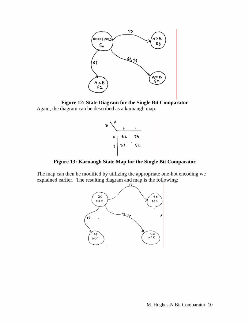
Figure 12: State Diagram for the Single Bit Comparator
Again, the diagram can be described as a karnaugh map.
Figure 13: Karnaugh State Map for the Single Bit Comparator
The map can then be modified by utilizing the appropriate one-hot encoding we explained earlier. The resulting diagram and map is the following:
M. Hughes-N Bit Comparator 10

Figure 14: Karnaugh Encoded State Diagram & Map for the Single Bit
Comparator Next, the map is described for each of the output (next state) bits. The start notation refers to which next state bit is being described through the karnaugh map. The following explains the notation. Notation: Description: A 1-bit primary input from vector A B 1-bit primary input from vector B *G 1-bit output describing “greater than”
status of the current primary and cascaded inputs
*E 1-bit output describing “equal to” status of the current primary and cascaded inputs
*L 1-bit output describing “less than” status of the current primary and cascaded inputs
Using this notation, the following explains the map for each individual output.
M. Hughes-N Bit Comparator 11
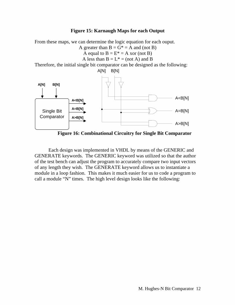
Figure 15: Karnaugh Maps for each Output
From these maps, we can determine the logic equation for each ouput. A greater than B = G* = A and (not B)
A equal to B = E* = A xor (not B) A less than B = L* = (not A) and B
Therefore, the initial single bit comparator can be designed as the following:
Single BitComparator
A[N] B[N]
A<B[N]
A>B[N]
A=B[N]
A[N] B[N]
A<B[N]
A=B[N]
A>B[N]
Figure 16: Combinational Circuitry for Single Bit Comparator
Each design was implemented in VHDL by means of the GENERIC and GENERATE keywords. The GENERIC keyword was utilized so that the author of the test bench can adjust the program to accurately compare two input vectors of any length they wish. The GENERATE keyword allows us to instantiate a module in a loop fashion. This makes it much easier for us to code a program to call a module “N” times. The high level design looks like the following:
M. Hughes-N Bit Comparator 12

Source Code(All Cascading
Single BitComparators)
Test Bench
Generic Specification
GndVdd
InputAB
N-bits
Gnd & Vdd Constants
A & B N-bit Vectors
A<B
A=B
A>B
Figure 17: High Level View of VHDL Implementation of Design with All
Cascading Single Bit Comparators with Test Bench
Source Code(1 Single Bit
Comparator and N-1Cascading SingleBit Comparators)
Test Bench
Generic Specification
InputAB
N-bits
A & B N-bit Vectors
A<B
A=B
A>B
M. Hughes-N Bit Comparator 13

Figure 18: High Level View of VHDL Implementation of Design with 1 Single Bit Comparator and N-1 Cascading Single Bit Comparators with Test Bench
Verification: Both designs were implemented and verified in ModelSim using VHDL. Each design approach was tested with the same specifications for N in the comparator as well as with the same test vectors for each test. The test was run for a 1-bit, 2-bit, 4-bit and 8-bit comparator. Please refer to the “Simulation Results” section for further evidence of verification. VHDL Implementation: Source Code: --This entity and architecture describes the cascading single bit comparator. This --comparator receives two 1-bit primary inputs as well as three cascaded control inputs --which refer to the relational status of the previous pair of bits. The design yields --three one bit outputs. If the three outputs are concatenated, the three-bit output is --expressed in one-hot form. ENTITY cascading_single_bit_comparator IS PORT (a, b, carryin_lessthan, carryin_equal, carryin_greaterthan: IN BIT; lessthan, equal, greaterthan: OUT BIT); END cascading_single_bit_comparator; ARCHITECTURE dataflow OF cascading_single_bit_comparator IS BEGIN --the following three statements are the implementation of the circuitry designed for the -- cascading single bit comparator earlier in the report --if A is 0 and B is 1 or if the carryin_lessthan signal is asserted then A is "less --than" B so the "lessthan" output is driven high lessthan<=(carryin_lessthan OR (carryin_equal AND (NOT a) AND b)); --if the carryin_equal signal is asserted and not A does not equal B then A is equal to B --and the "equal" output is driven high
equal<=(carryin_equal AND ((NOT a) XOR b)); --if A is 1 and B is 0 or if the carryin_greaterthan signal is asserted then A is --"greater than" B so the "greaterthan" output is driven high
greaterthan<=(carryin_greaterthan OR (carryin_equal AND a AND (NOT b))); END dataflow;
Code 1: Source Code for Cascading Single Bit Comparator
--This all iterative component uses N blocks of the cascading single bit comparators. --Receives two N-bit input vectors A and B for comparison. Since this design uses all --cascading single bit comparators, three control (carry-in) inputs are needed for the --first component. Component outputs three one-bit outputs. ENTITY n_bit_comparator_all_iterative IS
M. Hughes-N Bit Comparator 14
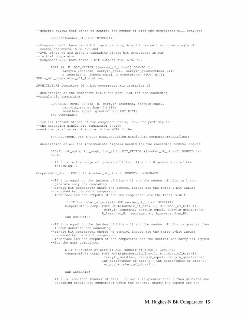
--generic allows test bench to control the number of bits the comparator will evaluate GENERIC(number_of_bits:INTEGER); --Component will have two N bit input vectors, A and B, as well as three single bit --conrol operators, A<B, A>B and --A=B, since we are using a cascading single bit comparator as our --initial comparator. --Component will have three 1-bit outputs A>B, A<B, A=B PORT (A, B: BIT_VECTOR ((number_of_bits-1) DOWNTO 0); carryin_lessthan, carryin_equal, carryin_greaterthan: BIT; A_lessthan_B, inputs_equal, A_greaterthan_B:OUT BIT); END n_bit_comparator_all_iterative; ARCHITECTURE iterative OF n_bit_comparator_all_iterative IS --declaration of the component title and port list for the cascading --single bit comparator
COMPONENT comp1 PORT(a, b, carryin_lessthan, carryin_equal, carryin_greaterthan: IN BIT;
lessthan, equal, greaterthan: OUT BIT); END COMPONENT; --for all instantiations of the component title, link the port map to --the cascading_single_bit_comparator entity --and the dataflow architecture in the WORK folder FOR ALL:comp1 USE ENTITY WORK.cascading_single_bit_comparator(dataflow); --declaration of all the intermediate signals needed for the cascading control inputs SIGNAL int_agtb, int_aeqb, int_altb: BIT_VECTOR ((number_of_bits-2) DOWNTO 0); BEGIN
--if i is in the range of (number of bits - 1) and ) 0 generate on of the --following...
CompareBitN_1to1: FOR i IN (number_of_bits-1) DOWNTO 0 GENERATE
--if i is equal to the (number of bits - 1) and the number of bits is 1 then --generate only one cascading --single bit comparator where the control inputs are the three 1-bit inputs --provided by the N-bit comparator
--interface and the outputs of the one comparator are the final result
i1:IF i=(number_of_bits-1) AND number_of_bits=1 GENERATE CompareBitN: comp1 PORT MAP(A(number_of_bits-1), B(number_of_bits-1), carryin_lessthan, carryin_equal, carryin_greaterthan, A_lessthan_B, inputs_equal, A_greaterthan_B); END GENERATE;
--if i is equal to the (number of bits - 1) and the number of bits is greater than --1 then generate one cascading --single bit comparator wheret he control inputs are the three 1-bit inputs --provided by the N-bit comparator --interface and the outputs of the comparator are the control (or carry-in) inputs --for the next comparator
N:IF i=(number_of_bits-1) AND (number_of_bits>1) GENERATE
CompareBitN: comp1 PORT MAP(A(number_of_bits-1), B(number_of_bits-1), carryin_lessthan, carryin_equal, carryin_greaterthan,
int_altb(number_of_bits-2), int_aeqb(number_of_bits-2), int_agtb(number_of_bits-2));
END GENERATE;
--if i is less than (number of bits - 1) but i is greater than 0 then generate one --cascading single bit comparator where the control (carry-in) inputs are the
M. Hughes-N Bit Comparator 15

--outputs of the previous comparator and the outputs of the current comparator are --the control (carry-in) inputs to the next comparator
Nto0:IF i>0 AND i<(number_of_bits-1) GENERATE CompaterBitN: comp1 PORT MAP (A(i-1), B(i-1), int_altb(i), int_aeqb(i), int_agtb(i), int_altb(i-1), int_aeqb(i-1), int_agtb(i-1)); END GENERATE;
--if i is equal to 0 and the number of bits is greater than 1 then generate only --one cascading single bit comparator where the control (carry-in) inputs are the --previous comparator's outputs and the outputs of the current comparator are the --final result
i2:IF i=0 AND (number_of_bits>1)GENERATE CompareBit0: comp1 PORT MAP(A(0), B(0), int_altb(0), int_aeqb(0), int_agtb(0), A_lessthan_B, inputs_equal, A_greaterthan_B); END GENERATE; END GENERATE; END iterative;
Code 2: Source Code for N-Bit Comparator Using N Cascading Single Bit Comparators (All Iterative Design)
*Note: Design One is Complete --Declaration of entity for component used when you do not want cascading inputs --on your first component. This components takes two 1-bit inputs and determine which --one is greater or if they are equal. System has three primary outputs. If the outputs --are taken as a --three bit output, the output is read in one-hot form. ENTITY initial_bit_comparator IS PORT (a, b: IN BIT; lessthan, equal, greaterthan: OUT BIT); END initial_bit_comparator; ARCHITECTURE dataflow OF initial_bit_comparator IS BEGIN --the following three statements are the implementation of the circuitry designed for the --cascading single bit comparator earlier in the report --if A is 0 and B is 1 then A is "less than" B so the "lessthan" output is driven high
lessthan<=((NOT a) AND b); --if not A does not equal B then A is "equal" to B so the "equal" output is driven high equal<=((NOT a) XOR b); --if A is 1 and B is 0 then A is "greater than" B so the "greaterthan" output is driven high greaterthan<=(a AND (NOT b)); END dataflow;
Code 3: Source Code for “initial” Single Bit Comparator
--This component uses an initial single bit comparator and N-1 blocks of the cascading --single bit comparators. Receives two N-bit input vectors A and B for comparison. --Component outputs three one-bit outputs ENTITY n_bit_comparator IS --generic allows test bench to control the number of bits the comparator will evaluate GENERIC(number_of_bits:INTEGER);
M. Hughes-N Bit Comparator 16

--Component will have two N bit input vectors, A and B, no single bit control inputs are --necessary since we are using the single bit comparator as our initial comparator --Component will have three 1-bit outputs A>B, A<B, A=B
PORT (A, B: BIT_VECTOR ((number_of_bits-1) DOWNTO 0); A_lessthan_B, inputs_equal, A_greaterthan_B:OUT BIT); END n_bit_comparator; ARCHITECTURE iterative OF n_bit_comparator IS --declaration of the component title and port list for the cascading single bit --comparator
COMPONENT comp1 PORT(a, b, carryin_lessthan, carryin_equal, carryin_greaterthan: IN BIT;
lessthan, equal, greaterthan: OUT BIT); END COMPONENT; --declaration of the component title and port list for the single bit comparator COMPONENT icomp PORT(a, b: IN BIT; lessthan, equal, greaterthan: OUT BIT); END COMPONENT; --for all instantiations of the component title comp1, link the port map to the --cascading_single_bit_comparator entity and the dataflow architecture in the WORK folder
FOR ALL:comp1 USE ENTITY WORK.cascading_single_bit_comparator(dataflow); --for all instantiations of the component title icomp, link the port map to the --initial_bit_comparator entity and the dataflow architecture in the WORK folder
FOR ALL:icomp USE ENTITY WORK.initial_bit_comparator(dataflow); --declare the intermediate signal necessary for the cascading of components SIGNAL int_agtb, int_aeqb, int_altb: BIT_VECTOR ((number_of_bits-2) DOWNTO 0); BEGIN
--if i is in the range of (number of bits - 1) and ) 0 generate on of the --following...
CompareBitN_1to1: FOR i IN (number_of_bits-1) DOWNTO 0 GENERATE
--if i is equal to the (number of bits - 1) and the number of bits is 1 then --generate only one single bit
--comparator where the outputs of the one comparator are the final result
i1:IF i=(number_of_bits-1) AND number_of_bits=1 GENERATE CompareBitN: icomp PORT MAP(A(number_of_bits-1), B(number_of_bits-1), A_lessthan_B, inputs_equal, A_greaterthan_B); END GENERATE;
--if i is equal to the (number of bits - 1) and the number of bits is greater than --1 then generate one single bit comparator where the outputs of the comparator --are the control (or carry-in) inputs for the next comparator
N:IF i=(number_of_bits-1) AND number_of_bits>1 GENERATE CompareBitN: icomp PORT MAP(A(number_of_bits-1), B(number_of_bits-1), int_altb(number_of_bits-2),
int_aeqb(number_of_bits-2), int_agtb(number_of_bits-2)); END GENERATE;
--if i is less than (number of bits - 1) but i is greater than 0 then generate one --cascading single bit comparator where the control (carry-in) inputs are the --outputs of the previous comparator and the outputs of the current comparator are --the control (carry-in) inputs to the next comparator
Nto0:IF i>0 AND i<(number_of_bits-1) GENERATE
CompaterBitN: comp1 PORT MAP (A(i-1), B(i-1), int_altb(i), int_aeqb(i), int_agtb(i), int_altb(i-1), int_aeqb(i-1), int_agtb(i-1));
M. Hughes-N Bit Comparator 17

END GENERATE;
--if i is equal to 0 and the number of bits is greater than 1 then generate only --one cascading single bit comparator where the control (carry-in) inputs are the --previous comparator's outputs and the outputs of the current comparator are the --final result
i2:IF i=0 AND (number_of_bits>1)GENERATE
CompareBit0: comp1 PORT MAP(A(0), B(0), int_altb(0), int_aeqb(0), int_agtb(0),
A_lessthan_B, inputs_equal, A_greaterthan_B); END GENERATE; END GENERATE; END iterative;
Code 4: Source Code for N-Bit Comparator Using Initial Single Bit Comparator and N-1 Cascading Single Bit Comparators
(Semi-Iterative Design) *Note: Design Two is Complete
Test Benches: --Test Bench created to instantiate the "all iterative" design using N cascading single --bit comparators In this test bench, N is equal to 1 (resulting in a 1 bit comparator) ENTITY test_bench_1_bit_all_iterative IS END test_bench_1_bit_all_iterative; ARCHITECTURE io OF test_bench_1_bit_all_iterative IS COMPONENT comparator GENERIC(number_of_bits:INTEGER:=1); PORT (A, B:IN BIT_VECTOR ((number_of_bits-1) DOWNTO 0); carryin_lessthan,
carryin_equal, carryin_greaterthan:IN BIT; A_lessthan_B, inputs_equal, A_greaterthan_B:OUT BIT); END COMPONENT; FOR ALL: comparator USE ENTITY WORK.n_bit_comparator_all_iterative(iterative); SIGNAL a, b: BIT_VECTOR (0 downto 0); SIGNAL agtrb, alssb, aeqb: BIT; SIGNAL gnd: BIT:='0'; SIGNAL vdd: BIT:='1'; BEGIN C1:comparator PORT MAP(a, b, gnd, vdd, gnd, alssb, aeqb, agtrb); a<="0", "1" AFTER 10 NS, "0" AFTER 20 NS; b<="0", "1" AFTER 5 NS, "0" AFTER 15 NS; END io;
Bench 1: Test Bench for 1 Bit Comparator Using the All Cascading Single Bit Comparator Approach
--Test Bench created to instantiate the "semi iterative" design using an initial single --bit comparator and N-1 cascading single bit comparators. --In this test bench, N is equal to 1 (resulting in a 1 bit comparator) ENTITY test_bench1 IS END test_bench1; ARCHITECTURE io OF test_bench1 IS COMPONENT comparator GENERIC(number_of_bits:INTEGER:=1);
M. Hughes-N Bit Comparator 18

PORT (A, B: BIT_VECTOR ((number_of_bits-1) DOWNTO 0); A_lessthan_B, inputs_equal, A_greaterthan_B:OUT BIT); END COMPONENT; FOR ALL: comparator USE ENTITY WORK.n_bit_comparator(iterative); SIGNAL a, b: BIT_VECTOR (0 downto 0); SIGNAL agtrb, alssb, aeqb: BIT; BEGIN C1:comparator PORT MAP(a, b, alssb, aeqb, agtrb); a<="0", "1" AFTER 10 NS, "0" AFTER 20 NS; b<="0", "1" AFTER 5 NS, "0" AFTER 15 NS; END io;
Bench 2: Test Bench for 1 Bit Comparator Using the Single Bit Comparator +
(N-1) Cascading Single Bit Comparators Approach --Test Bench created to instantiate the "all iterative" design using N cascading single --bit comparators. In this test bench, N is equal to 2 (resulting in a 2 bit comparator) ENTITY test_bench_2_bit_all_iterative IS END test_bench_2_bit_all_iterative; ARCHITECTURE io OF test_bench_2_bit_all_iterative IS COMPONENT comparator GENERIC(number_of_bits:INTEGER:=2); PORT (A, B:IN BIT_VECTOR ((number_of_bits-1) DOWNTO 0); carryin_lessthan, carryin_equal, carryin_greaterthan:IN BIT; A_lessthan_B, inputs_equal, A_greaterthan_B:OUT BIT); END COMPONENT; FOR ALL: comparator USE ENTITY WORK.n_bit_comparator_all_iterative(iterative); SIGNAL a, b: BIT_VECTOR (1 downto 0); SIGNAL agtrb, alssb, aeqb: BIT; SIGNAL gnd: BIT:='0'; SIGNAL vdd: BIT:='1'; BEGIN C1:comparator PORT MAP(a, b, gnd, vdd, gnd, alssb, aeqb, agtrb); a<="00", "10" AFTER 10 NS, "11" AFTER 20 NS, "01" AFTER 30 NS, "01" AFTER 35 NS; b<="01", "00" AFTER 5 NS, "10" AFTER 15 NS, "11" AFTER 25 NS; END io;
Bench 3: Test Bench for 2 Bit Comparator Using the All Cascading Single Bit Comparator Approach
--Test Bench created to instantiate the "semi iterative" design using an initial single --bit comparator and N-1 cascading single bit comparators. --In this test bench, N is equal to 2 (resulting in a 2 bit comparator) ENTITY test_bench_2_bit IS END test_bench_2_bit; ARCHITECTURE io OF test_bench_2_bit IS COMPONENT comparator GENERIC(number_of_bits:INTEGER:=2); PORT (A, B: BIT_VECTOR ((number_of_bits-1) DOWNTO 0); A_lessthan_B, inputs_equal, A_greaterthan_B:OUT BIT); END COMPONENT; FOR ALL: comparator USE ENTITY WORK.n_bit_comparator(iterative);
M. Hughes-N Bit Comparator 19

SIGNAL a, b: BIT_VECTOR(1 DOWNTO 0); SIGNAL agtrb, alssb, aeqb: BIT; --SIGNAL gnd: BIT:='0'; --SIGNAL vdd: BIT:='1'; BEGIN C1:comparator PORT MAP(a, b, alssb, aeqb, agtrb); a<="00", "10" AFTER 10 NS, "11" AFTER 20 NS, "01" AFTER 30 NS, "01" AFTER 35 NS; b<="01", "00" AFTER 5 NS, "10" AFTER 15 NS, "11" AFTER 25 NS; END io;
Bench 4: Test Bench for 2 Bit Comparator Using the Single Bit Comparator + (N-1) Cascading Single Bit Comparators Approach
--Test Bench created to instantiate the "all iterative" design using N cascading single --bit comparators. In this test bench, N is equal to 4 (resulting in a 4 bit comparator) ENTITY test_bench_4_bit_all_iterative IS END test_bench_4_bit_all_iterative; ARCHITECTURE io OF test_bench_4_bit_all_iterative IS COMPONENT comparator GENERIC(number_of_bits:INTEGER:=4); PORT (A, B:IN BIT_VECTOR ((number_of_bits-1) DOWNTO 0); carryin_lessthan, carryin_equal, carryin_greaterthan:IN BIT; A_lessthan_B, inputs_equal, A_greaterthan_B:OUT BIT); END COMPONENT; FOR ALL: comparator USE ENTITY WORK.n_bit_comparator_all_iterative(iterative); SIGNAL a, b: BIT_VECTOR(3 DOWNTO 0); SIGNAL agtrb, alssb, aeqb: BIT; SIGNAL gnd: BIT:='0'; SIGNAL vdd: BIT:='1'; BEGIN C1:comparator PORT MAP(a, b, gnd, vdd, gnd, alssb, aeqb, agtrb); a<="0000", "1000" AFTER 10 NS, "1111" AFTER 20 NS, "0001" AFTER 30 NS, "0111" AFTER 40 NS; b<="1100", "0000" AFTER 5 NS, "1111" AFTER 15 NS, "0010" AFTER 25 NS, "1010" AFTER 35 NS, "1010" AFTER 40 NS; END io;
Bench 5: Test Bench for 4 Bit Comparator Using the All Cascading Single Bit Comparator Approach
--Test Bench created to instantiate the "semi iterative" design using an initial single --bit comparator and N-1 cascading single bit comparators. --In this test bench, N is equal to 4 (resulting in a 4 bit comparator) ENTITY test_bench IS END test_bench; ARCHITECTURE io OF test_bench IS COMPONENT comparator GENERIC(number_of_bits:INTEGER:=4); PORT (A, B: BIT_VECTOR ((number_of_bits-1) DOWNTO 0); A_lessthan_B, inputs_equal, A_greaterthan_B:OUT BIT);
M. Hughes-N Bit Comparator 20

END COMPONENT; FOR ALL: comparator USE ENTITY WORK.n_bit_comparator(iterative); SIGNAL a, b: BIT_VECTOR(3 DOWNTO 0); SIGNAL agtrb, alssb, aeqb: BIT; --SIGNAL gnd: BIT:='0'; --SIGNAL vdd: BIT:='1'; BEGIN C1:comparator PORT MAP(a, b, alssb, aeqb, agtrb); a<="0000", "1000" AFTER 10 NS, "1111" AFTER 20 NS, "0001" AFTER 30 NS, "0111" AFTER 40 NS; b<="1100", "0000" AFTER 5 NS, "1111" AFTER 15 NS, "0010" AFTER 25 NS, "1010" AFTER 35 NS, "1010" AFTER 40 NS; END io;
Bench 6: Test Bench for 4 Bit Comparator Using the Single Bit Comparator + (N-1) Cascading Single Bit Comparators Approach
--Test Bench created to instantiate the "all iterative" design using N cascading single --bit comparators. In this test bench, N is equal to 8 (resulting in a 8 bit comparator) ENTITY test_bench_8_bit_all_iterative IS END test_bench_8_bit_all_iterative; ARCHITECTURE io OF test_bench_8_bit_all_iterative IS COMPONENT comparator GENERIC(number_of_bits:INTEGER:=8); PORT (A, B:IN BIT_VECTOR ((number_of_bits-1) DOWNTO 0); carryin_lessthan, carryin_equal, carryin_greaterthan:IN BIT; A_lessthan_B, inputs_equal, A_greaterthan_B:OUT BIT); END COMPONENT; FOR ALL: comparator USE ENTITY WORK.n_bit_comparator_all_iterative(iterative); SIGNAL a, b: BIT_VECTOR(7 DOWNTO 0); SIGNAL agtrb, alssb, aeqb: BIT; SIGNAL gnd: BIT:='0'; SIGNAL vdd: BIT:='1'; BEGIN C1:comparator PORT MAP(a, b, gnd, vdd, gnd, alssb, aeqb, agtrb); a<="01010000", "11010000" AFTER 10 NS, "00001101" AFTER 20 NS, "00100101" AFTER 30 NS, "10000111" AFTER 40 NS; b<="11010100", "11010000" AFTER 5 NS, "11000000" AFTER 15 NS, "00101111" AFTER 25 NS, "00101000" AFTER 35 NS, "10101000" AFTER 45 NS; END io;
Bench 7: Test Bench for 8 Bit Comparator Using the All Cascading Single Bit
Comparator Approach
--Test Bench created to instantiate the "semi iterative" design using an initial single --bit comparator and N-1 cascading single bit comparators. --In this test bench, N is equal to 8 (resulting in a 8 bit comparator) ENTITY test_bench_8_bit IS END test_bench_8_bit;
M. Hughes-N Bit Comparator 21

ARCHITECTURE io OF test_bench_8_bit IS COMPONENT comparator GENERIC(number_of_bits:INTEGER:=8); PORT (A, B: BIT_VECTOR ((number_of_bits-1) DOWNTO 0); A_lessthan_B, inputs_equal, A_greaterthan_B:OUT BIT); END COMPONENT; FOR ALL: comparator USE ENTITY WORK.n_bit_comparator(iterative); SIGNAL a, b: BIT_VECTOR(7 DOWNTO 0); SIGNAL agtrb, alssb, aeqb: BIT; --SIGNAL gnd: BIT:='0'; --SIGNAL vdd: BIT:='1'; BEGIN C1:comparator PORT MAP(a, b, alssb, aeqb, agtrb); a<="01010000", "11010000" AFTER 10 NS, "00001101" AFTER 20 NS, "00100101" AFTER 30 NS, "10000111" AFTER 40 NS; b<="11010100", "11010000" AFTER 5 NS, "11000000" AFTER 15 NS, "00101111" AFTER 25 NS, "00101000" AFTER 35 NS, "10101000" AFTER 45 NS; END io;
Bench 8: Test Bench for 8 Bit Comparator Using the Single Bit Comparator + (N-1) Cascading Single Bit Comparators Approach
Simulation:
Figure 19: Waveform Results for test_bench_1_bit_all_iterative (All Cascading Single Bit Comparator Approach)
M. Hughes-N Bit Comparator 22

Figure 20: Waveform Results for test_bench_1_bit (Single Bit Comparator + (N-1) Cascading Single Bit Comparators
Approach)
Figure 21: Waveform Results for test_bench_2_bit_all_iterative (All Cascading Single Bit Comparator Approach)
Figure 22: Waveform Results for test_bench_2_bit (Single Bit Comparator + (N-1) Cascading Single Bit Comparators
Approach)
M. Hughes-N Bit Comparator 23

Figure 23: Waveform Results for test_bench_4_bit_all_iterative (All Cascading Single Bit Comparator Approach)
Figure 24: Waveform Results for test_bench_4_bit (Single Bit Comparator + (N-1) Cascading Single Bit Comparators
Approach)
Figure 25: Waveform Results for test_bench_8_bit_all_iterative (All Cascading Single Bit Comparator Approach)
M. Hughes-N Bit Comparator 24

Figure 26: Waveform Results for test_bench_8_bit (Single Bit Comparator + (N-1) Cascading Single Bit Comparators
Approach)
Limitations & Improvements: The design obviously is implemented to only support two N-bit inputs. Further design could include resolving this limitation. The design could be implemented to compare “M” inputs of size “N.” The input could be a 2 dimensional array specified by the two generic statements (M and N). If this were to be implemented, the “generate” statements could prove tricky and tedious. Also, another improvement could be translating the current circuitry to all NAND gates since NAND gates are the least costly 2-input devices in terms of delay and resistance digital design (due to P-fets in parallel rather than series).
M. Hughes-N Bit Comparator 25


![A High-Speed 64-Bit Binary Comparator€¦ · A high-speed 64-bit binary comparator 39 | Page III. EXISTING 64-BIT BINARY COMPARATOR DESIGN 64-bit comparator in reference [8], [9],](https://img.dokumen.tips/doc/110x75/5eac1a458d19873e777698b4/a-high-speed-64-bit-binary-comparator-a-high-speed-64-bit-binary-comparator-39-.jpg)


