Embed Size (px)
Citation preview


A - 1 A - 1
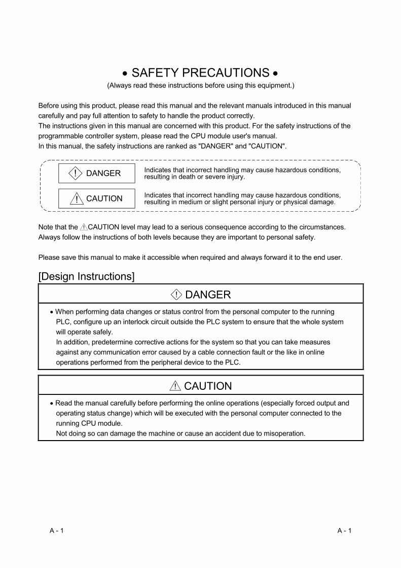
• SAFETY PRECAUTIONS • (Always read these instructions before using this equipment.)
Before using this product, please read this manual and the relevant manuals introduced in this manual carefully and pay full attention to safety to handle the product correctly. The instructions given in this manual are concerned with this product. For the safety instructions of the programmable controller system, please read the CPU module user's manual. In this manual, the safety instructions are ranked as "DANGER" and "CAUTION".
! DANGER
CAUTION!
Indicates that incorrect handling may cause hazardous conditions,resulting in death or severe injury.
Indicates that incorrect handling may cause hazardous conditions, resulting in medium or slight personal injury or physical damage.
Note that the ! CAUTION level may lead to a serious consequence according to the circumstances. Always follow the instructions of both levels because they are important to personal safety. Please save this manual to make it accessible when required and always forward it to the end user. [Design Instructions]
! DANGER • When performing data changes or status control from the personal computer to the running
PLC, configure up an interlock circuit outside the PLC system to ensure that the whole system will operate safely. In addition, predetermine corrective actions for the system so that you can take measures against any communication error caused by a cable connection fault or the like in online operations performed from the peripheral device to the PLC.
! CAUTION • Read the manual carefully before performing the online operations (especially forced output and
operating status change) which will be executed with the personal computer connected to the running CPU module. Not doing so can damage the machine or cause an accident due to misoperation.

A - 2 A - 2
REVISIONS
* The manual number is given on the bottom left of the back cover.
Print Date * Manual Number Revision Apr., 2002 SH (NA)-080272-A First edition Jun., 2002 SH (NA)-080272-B Correction
Operating Instructions Dec., 2003 SH (NA)-080272-C Correction
Operating Instructions, Section 3.2, Section 3.3, Section 4.1, Section 6.1
Addition Generic Terms and Abbreviations, Section 1.1, Subsection 1.2.1, Section 3.1, Subsection 3.3.17, Subsection 4.2.9, Subsection 4.2.10, Subsection 4.2.11, Subsection 4.2.12, Subsection 4.2.14, Appendix 3.1
Jun., 2004 SH (NA)-080272-D Model Addition Q12PRHCPU, Q25PRHCPU, FX3UCCPU
New Addition Subsection 2.1.5, Subsection 5.1.3, Section 5.6, Section 5.7
Correction Subsection 4.3.17
Addition Generic Terms and Abbreviations, Section 2.2, Section 3.2, Section 3.3, Section 4.1, Section 4.2, Chapter 5, Section 6.1
Aug., 2004 SH (NA)-080272-E Correction Operating Instructions
Addition Section 2.3, Section 3.2, Subsection 3.3.26
Aug., 2005 SH (NA)-080272-F Model Addition FX3UCPU
Addition Generic Terms and Abbreviations, Section 3.2, Subsection 3.3.2, Subsection 3.3.3, Subsection 3.3.22, Subsection 3.3.23, Subsection 4.2.9, Subsection 4.2.10, Subsection 4.2.11, Subsection 4.2.12, Subsection 4.2.13, Subsection 4.2.14, Section 6.1
Nov., 2006 SH (NA)-080272-G Correction Section 1.1, Section 4.1

A - 3 A - 3
Print Date * Manual Number Revision Oct., 2007 SH (NA)-080272-H Model Addition
Q02UCPU, Q03UDCPU, Q04UDHCPU, Q06UDHCPU
New Addition Subsection 3.3.25, Subsection 5.8, Subsection 5.9
Addition Operating Instructions, Manuals, Generic Terms and Abbreviations, Section 1.1, Section 1.2, Subsection 2.1.5, Chapter 3, Subsection 4.2.9, Subsection 4.2.10, Subsection 4.2.11, Subsection 4.2.12, Subsection 4.2.13, Subsection 4.2.14, Chapter 5, Section 6.1, Section 6.2, Appendix 3
Jun., 2008 SH (NA)-080272-I Model Addition Q13UDHCPU, Q26UDHCPU
Correction Operating Instructions, Manuals, Generic Terms and Abbreviations, Section 1.1, Section 3.1, Section 3.2, Subsection 3.3.2 to Subsection 3.3.26, Subsection 3.3.29 to Subsection 3.3.33, Subsection 4.2.13, Section 6.2, Appendix 3.1, Appendix 3.2, Appendix 3.3
Sep., 2008 SH (NA)-080272-J Model Addition Q03UDECPU, Q04UDEHCPU, Q06UEDHCPU, Q13UDEHCPU, Q26UDEHCPU, QS001CPU, Q02PHCPU, Q06PHCPU
New Addition Subsection 3.3.8, Subsection 3.3.9
Addition Operating Instructions, Generic Terms and Abbreviations, Section 1.1, Subsection 1.2.1, Section 2.3, Section 3.1, Section 3.2, Subsection 3.3.1, Subsection 4.2.9 to Subsection 4.2.14, Section 6.1, Appendix 3
Dec., 2008 SH (NA)-080272-K Model Addition Q00UJCPU, Q00UCPU, Q01UCPU, Q10UDHCPU, Q10UDEHCPU, Q20UDHCPU, Q20UDEHCPU, FX3GCPU
New Addition Subsection 3.3.20
Addition Operating Instructions, Section 1.1, Subsection 1.2.1, Section 3.1, Section 3.2, Subsection 3.3.10,Subsection 3.3.14, Subsection 3.3.15, Subsection 3.3.21, Subsection 4.2.9 to Subsection 4.2.14, Appendix 3
Japanese Manual Version SH-080275-K
This manual confers no industrial property rights or any rights of any other kind, nor does it confer any patent licenses. Mitsubishi Electric Corporation cannot be held responsible for any problems involving industrial property rights which may occur as a result of using the contents noted in this manual.
© 2002 MITSUBISHI ELECTRIC CORPORATION

A - 4 A - 4
Operating Instructions
This section gives explanation of instructions in the following order. 1) Instructions for used OS and personal computer 2) Instructions for installation and uninstallation 3) PLC CPU-related instructions 4) Instructions for use of other MELSOFT products 5) Instructions for use of Ethernet modules 6) Instructions for use of CC-Link modules 7) Instructions for use of MELSECNET(II), MELSECNET/10 and MELSECNET/H 8) Instructions for use of computer link and serial communication modules 9) Instructions for modem communication 10) Instructions for programming 11) Instructions for use of Microsoft R Excel 12) Instructions for use of Microsoft R Access 13) Instructions for use of VBScript and ASP function
Instructions for used OS and personal computer
(1) When using Microsoft R Windows NT R Workstation Operating System Version 4.0,
Microsoft R Windows R 2000 Professional Operating System, Microsoft R Windows R XP Professional and Microsoft R Windows R XP Home Edition, Microsoft R Windows Vista R Home Basic Operating System, Microsoft R Windows Vista R Home Premium Operating System, Microsoft R Windows Vista R Business Operating System, Microsoft R Windows Vista R Ultimate Operating System or Microsoft R Windows Vista R Enterprise Operating System
Note that the following restrictions apply when a user without Administrator’s authority operates MX Component. (a) Communication Setup Utility
• The logical station number cannot be created, changed or deleted. • Target settings cannot be imported. • This utility cannot be started up if the communication settings have been
made using MX Component earlier than Version3.00A. *1 (b) PLC Monitor Utility
• This utility cannot be started up if the communication settings have been made using MX Component earlier than Version3.00A. *1
• Device registration cannot be performed on "Entry Device" tab. (c) Communication board
• Various settings cannot be made on the CC-Link IE Controller Network, MELSECNET/H, MELSECNET/10, MELSECNET(II), CC-Link, AF and CPU board utilities.
*1: If the following error message appears, start up and close the utility as a user with Administrator’s authority, once. This operation enables a user without Administrator’s authority to start up the utility.
(2) About Ethernet communication, computer link communication and CPU COM
communication on Microsoft R Windows R 95 Operating System (a) Making Ethernet communication using TCP/IP and UDP/IP on Windows R 95
of the version older than OSR2 will cause a memory leak. When performing continuous operation on Windows R 95, use Window R 95 OSR2 or later.

A - 5 A - 5
(b) On Windows R 95, communication using the COM port, e.g. computer link
communication or CPU COM communication, will cause a memory leak. Therefore, do not perform continuous operation.
(3) Precautions for use of Microsoft R Windows R Millennium Edition Operating System
It is not recommended to use MX Component with the "system restoring function" made invalid by the operating system. If the free space of the system drive becomes less than 200MB, the "system restoring function" is made invalid by the operating system. When using Windows R Me, reserve a 200MB or more free space for the system drive.
(4) About the resume and other functions of personal computer
A communications error may occur if communications are made with the PLC CPU after setting the resume function, suspend setting, power-saving function and/or standby mode of the personal computer. Therefore, do not set the above functions when making communications with the PLC CPU.
(5) Restrictions by DEP (Data Execution Prevention)
Note that restrictions by DEP may apply when using Microsoft R Windows R XP Service Pack2 or later, or Microsoft R Windows Vista R . For restrictions by DEP, refer to the following manual. MX Component Version 3 Operating Manual
Instructions for installation and uninstallation
(1) About installation
(a) When performing overwrite installation, install the software in the folder where it had already been installed.
(b) If you install the MELSEC board driver or GX Developer into the personal computer where MX Component has already been installed, communication using a specific path (e.g. ASCII packet of the AJ71E71) may result in a receive, device number or other error. If any of these phenomena has occurred, perform overwrite installation of MX Component again.
(2) Precautions for performing installation and uninstallation on a dual boot machine
where two different operating systems are installed in a single IBM-PC/AT compatible personal computer
On a dual boot machine having Windows NT R Workstation 4.0 (hereafter referred to as OS1) and Windows R 95 or Windows R 98 (hereafter referred to as OS2), note the following points when MX Component was installed on OS1 first and MX Component was then installed over the same folder on OS2. (a) If MX Component is uninstalled first on the OS2 side, uninstallation does not
delete the control DLLs and ACT folders, and they remain within the IBM-PC/AT compatible. To delete the control DLLs and ACT folders, perform uninstallation also on the OS1 side.
(b) If MX Component is uninstalled first on the OS1 side, the control DLLs and ACT folders are deleted. In this case, MX Component may not operate properly or cannot be uninstalled on the OS2 side. Install MX Component again on the OS2 side to operate MX Component properly or uninstall it on the OS2 side.
A - 6 A - 6
(3) About start menu
When you have uninstalled MX Component, the item may remain in the start menu. In that case, restart the IBM-PC/AT compatible personal computer.
PLC CPU-related instructions
(1) About transmission speed
As the transmission speed of the QCPU(Q mode) and QCPU(A mode), you can set 9600bps, 19200bps, 38400bps, 57600bps or 11520bps. For the QnACPU of version 9707B or later, you can set the transmission speed of 9600bps, 19200bps or 38400bps. For the QnACPU of other versions, you can set 9600bps or 19200bps. The transmission speeds of the ACPU (except A2USHCPU-S1), FXCPU and motion controller CPU are fixed to 9600bps. (The A2USHCPU-S1 may be set to 19200bps.)
(2) Precautions for USB communication
Frequently disconnecting/reconnecting the USB cable or resetting or powering ON/OFF the PLC CPU during communications with the PLC CPU may cause a communications error which cannot be recovered. If it is not recovered, completely disconnect the USB cable once and then reconnect it after 5 or more seconds have elapsed. (If this error occurs at the initial communication after the above operation, the function will be performed properly in and after the second communications.)
(3) About clock data of the PLC CPU
(a) For the ACPU (including the motion controller CPU), clock data setting may be made only when the PLC CPU is in the STOP status. For the QCPU (Q mode), QCPU (A mode), QnACPU and FXCPU, clock data setting may be made if the PLC CPU is in the RUN status.
(b) For the A0J2HCPU, A2CCPU and A2CJCPU, setting cannot be made as they do not have the clock function.
(c) For the ACPU, setting can be made independently of whether the clock setting special relay "M9028" is ON or OFF. (Note that the special relay "M9028" turns OFF after execution.) For the QCPU (Q mode), QCPU (A mode) and QnACPU, setting can be made independently of whether the clock setting device "SM1028" is ON or OFF.
(d) Among the FXCPUs, setting may be made for only the FX1N (clock built-in), FX1NC (clock built-in), FX1S (clock built-in), FX2N (clock built-in), FX2NC (when RTC cassette is fitted), FX2 (when RTC cassette is fitted) and FX2C (when RTC cassette is fitted). FX3G (clock built-in).
(e) Note that an error for transfer time will be produced in clock setting.
(4) Precautions for use of Q4ARCPU The duplexing function cannot be used.
A - 7 A - 7
(5) Restrictions on use of the FXCPU
(a) When the FXCPU is used, access to the TN devices (timer present values) or CN devices (counter present values) is not permitted if the device numbers specified are split across 199 or earlier and 200 or later.
(b) As the FXCPU does not have a PAUSE switch as the PLC CPU, an error is returned if remote pause is specified in SetCpuStatus.
(c) Note that specifying the first I/O number of a nonexisting module and executing the WriteBuffer( ) method will not return an error.
(d) For the index registers (Z, V) of the FXCPU, data cannot be written to 2 or more consecutive points using WriteDeviceBlock(). (Data may be written to only one point.)
(6) Serial communication function of Q00UJ/Q00/Q00U/Q01/Q01U/Q02U/CPU*1
*1: In this paragraph, "serial communication function compatible CPU" indicates Q00UJ/Q00/Q00U/Q01/Q01U/Q02UCPU.
When the following conditions are all satisfied, communication between the personal computer and the serial communication function compatible CPU is made at 9600bps speed.
1) The serial communication function of the connected CPU is valid. 2) The personal computer side transmission speed setting differs from the
serial communication function compatible CPU side transmission speed setting.
To increase the communication speed, match the personal computer side transmission speed with the serial communication function compatible CPU side transmission speed.
(7) Precautions for use of Built-in Ethernet port QCPU
If you reset the PLC CPU during TCP/IP connection setting (during opening) using MX Component, a communication or receive error will occur at the time of communication after that. In that case, close the application that uses MX Component and then perform open processing again.
(8) Precautions for use of QSCPU
In order to protect the safety PLC system, functions writing to buffer memory, writing and setting devices and writing clock data cannot be executed.
Instructions for use of other MELSOFT products
(1) About simultaneous use of MX Component and GX Developer
When using GX Developer and MX Component together for the same E71 module to make Ethernet communication, make the following settings. (a) Set the protocol of the communication setting wizard screen to "UDP/IP". (b) Set "SW2" of the communications setting switches of the E71 module to
OFF (binary). (2) Precautions for GX Simulator communication
Before executing the monitor utility, communication setting utility or user program, make sure that GX Simulator and GX Developer are operating. In addition, do not terminate the GX Simulator and GX Developer while the user program is running. If you do so, you will not be able to terminate the user program normally.
A - 8 A - 8
Instructions for use of Ethernet modules
(1) Resetting PLC CPU during TCP/IP connection setting
If you reset the PLC CPU during TCP/IP connection setting (during opening) using MX Component, a communication or receive error will occur at the time of communication after that. In that case, close the application that uses MX Component and then perform open processing again.
(2) About target existence check starting interval*1 of Ethernet module
If close processing (Close) is executed from the IBM-PC/AT compatible, the Ethernet module may not perform close processing (Close). One of its causes is the open cable. If open processing (Open) is executed from the IBM-PC/AT compatible with the Ethernet module not performing close processing (Close), open processing (Open) from the IBM-PC/AT compatible is not terminated normally until the Ethernet module makes a target existence check and executes close processing (Close). If you want to terminate open processing (Open) early from the IBM-PC/AT compatible, shorten the target existence check starting interval setting of the Ethernet module. (The target existence check starting interval setting of the Ethernet module defaults to 10 minutes.) *1: It can be set for the E71 of AJ71E71-S3 or later.
(3) Replacement of Ethernet module
If you changed the Ethernet module during Ethernet communication due to debugging, failure or like, the other node (IBM-PC/AT compatible) must be restarted. (Since the Ethernet addresses (MAC addresses) differ between devices)
(4) Simultaneous access when using Q series-compatible Ethernet module
The following conditions should be satisfied when communication is to be made simultaneously from multiple IBM-PC/AT compatibles to the same module using the TCP/IP protocol. • Q series-compatible E71 module (except QJ71E71-100) whose first five digits
of the serial number is "02122" or later and whose function version is B or later.
• Using GX Developer Version 6.05F or later, set "MELSOFT connection" in the Ethernet parameter "open system".

A - 9 A - 9
(5) Unlocking password when using QJ71E71
The range where the password can be unlocked by remote operation is up to the connection target station. If the password is set also on the lower layer, communication cannot be made with the PLC CPU on the lower layer.
AAAA
Startingsource
1)QJ71E71
QCPU(Qmode)
2)QJ71E71
5)QJ71E71
4)QJ71E71
QCPU(Qmode)
3)QJ71E71
1)2)3)4)5)
Ethernet
Ethernet
Without setting
1) Unlocking QJ71E71 password enables access to PLC CPUs in this range.
: Accessible: Inaccessible
Enter password tounlock.
QCPU(Qmode)
QCPU(Qmode)
No. Remote PasswordWith setting (AAAA)Without settingWith setting (AAAA)With setting (BBBB)
(6) About use of the Q4ARCPU When using the UDP/IP protocol of Ethernet communication, use the Q4ARCPU whose year and month of manufacture is "0012" or later and whose function version is B or later.
(7) About Ethernet communication
(a) When access is made to the QnACPU, AnUCPU, QCPU (A mode) or motion controller CPU via the E71, the device range is equivalent to that of the AnACPU.
(b) When making access to the PLC CPU through Ethernet communication, the functions may not be executed depending on the PLC CPU status. 1) When the protocol is TCP/IP (target module: E71, QE71)
The functions can be executed only when the communication target PLC CPU is in the RUN mode. An error is returned if the PLC CPU is in other than the RUN mode.
2) When the protocol is UDP/IP (target module: E71, QE71) The functions cannot be executed until the communication target PLC CPU is RUN once. An error is returned if the PLC CPU has not been RUN once.

A - 10 A - 10
(c) The communication line is broken if the CPU becomes faulty or the Ethernet
module is reset during Ethernet communication (when the protocol is TCP/IP). In that case, perform line close processing (Close) and then execute reopen processing (Open).
(d) When two different communication systems (protocols) are used to make access from one IBM-PC/AT compatible to one Q series-compatible E71, two station numbers, i.e. for TCP/IP and for UDP/IP, must be set. However, it is not required to set different station numbers for TCP/IP and UDP/IP when using MX Component Version 3 or later and Q series-compatible E71 with serial No. 05051 or later.
(Example) When MX Component uses TCP/IP and GX Developer uses
UDP/IP
Q series-compatible E71(Station number: 1)
(TCP/IP) station number for MX Component: 2(UDP/IP) station number for GX Developer : 3
IBM-PC/AT compatible
GX Developer(UDP/IP)
MX Component(TCP/IP)
Set different station numbers as the (TCP/IP) station number for MX Componentand (UDP/IP) station number for GX Developer. If they are set to the same stationnumber, an error will occur on the Ethernet module side.
(8) About switch settings of E71 and QE71
If the four lower digits of the error code that occurred during Ethernet communication using the E71 or QE71 is not indicated in the E71 or QE71 manual, check the DIP switch (SW2) setting of the E71 or QE71. If the DIP switch is not set correctly, a difference has occurred in the packet format (ASCII/binary) and therefore the error code returned from the module cannot be recognized correctly.
Instructions for use of CC-Link modules
(1) Software version of CC-Link master/local module
As the CC-Link master/local module used in CC-Link communication or CC-Link G4 communication(only when the AJ65BT-G4 is used), use the module of software version "N" or later. The module of software version "M" or earlier will not operate properly.
(2) Software version of CC-Link G4 module
As the CC-Link G4 module used in CC-Link G4 communication(only when the AJ65BT-G4 is used), use the module of software version "D" or later. The module of software version "C" or earlier will not operate properly.
A - 11 A - 11
Instructions for use of MELSECNET(II), MELSECNET/10 and MELSECNET/H
(1) About relaying from the MELSECNET/10 loaded station
When the module is loaded to the AnNCPU or AnACPU, it is recognized as a MELSECNET(II) module. When the connected station is the AnNCPU or AnACPU, set the relayed network as MELSECNET(II). In addition, set the station number to "0" when making access to the control station.
(2) Instructions for relaying the MELSECNET(II)
When access is made to the QnACPU, AnUCPU, QCPU (A mode) or motion controller CPU via the MELSECNET(II), the device range is equivalent to that of the AnACPU.
Instructions for use of computer link and serial communication modules
(1) About computer link communication
(a) If the connected station CPU is the AnUCPU and the computer link module is the UC24 for computer link connection, remote operation will result in an error when access is made to the AnNCPU, AnACPU or QnACPU via the MELSECNET/10.
(b) On any computer link modules other than the UC24 and C24, remote "PAUSE" operation will result in an error for all connections.
(c) For the QC24, note that the illegal case of specifying the first I/O number of a nonexisting module and reading/writing U \G will not return an error if the software version of the module is "k" or earlier.
(d) In any connection form (direct coupling, relaying) where the target station of the UC24 or C24 is the QnACPU, an error is returned if clock data read/write is executed.
(e) The FX extended port is required when performing the computer link communication using FX0N, FX1S, FX1N(C), FX2N(C), FX3G, FX3U(C) CPU.
(2) Precautions for connecting personal computer and serial communication module
(a) When QJ71C24-R2 of function version A is used An MX Component application can use only either of CH1 and CH2. When the MELSOFT product, such as GX Developer or GOT, is using one channel, the application cannot use the other channel. When the QJ71C24-R2 of function version B is used, the application can use both channels.
(b) When AJ71QC24-R2 or A1SJ71QC4-R2 or AJ71QC24N-R2 or A1SJ71QC24N-R2 is used The MX Component application can use only CH1. It cannot use CH2.
A - 12 A - 12
Instructions for modem communication
(1) Simultaneous modem communications
It is not allowed to simultaneously perform modem communications using MX Component and other application such as GX Developer. Do not perform a modem communication using other applications during a modem communication using MX Component. If modem communications are simultaneously performed using MX Component and other application, this will result in a communication error, disconnection of telephone line or similar problem.
(2) Instructions for use of telephone line
(a) Do not use the call-waiting phone line. On the call-waiting phone line, data corruption, telephone line disconnection or similar may occur due to interrupt reading sounds.
(b) Do not connect the line to master/slave phones. If the handset of the slave phone is lifted while the telephone line is connecting to the master/slave phones, the telephone line may be disconnected.
(c) Use an analog 2 wire type telephone line. When using a digital line, use a terminal adaptor. When the telephone line is of 4 wire type, the line may not be connected depending on the wiring type of the modular jack. For the 4 wire type, conduct connection tests in advance to check for connection.
(3) Instructions for use of cellular phone
(a) Modem for radio communication using a cellular phone Although the modem name is different depending on the maker, the modem is generically referred to as the cellular phone communication unit in this manual. Select the model of the cellular phone communication unit according to the cellular phone used. For details, contact the company of your cellular phone.
(b) Cellular phone without auto answer function For the cellular phone without auto answer function, use a cellular phone communication unit that has the ANS/ORG/TEL select switch. If the cellular phone communication unit does not have the ANS/ORG/TEL select switch, it is impossible to connect the line. The line connection procedure is different depending on the cellular phone company and cellular phone model. For details, contact the maker of your cellular phone.
A - 13 A - 13
Instructions for programming
(1) About sample programs, test programs and sample sequence programs
(a) Sample programs, test programs The sample programs are attached for your reference to create user programs. The test programs are attached to conduct communication tests. Use these programs on your own responsibility.
(b) Sample sequence programs The sample sequence programs attached to MX Component must be modified depending on the system configuration and parameter settings. Modify them to be best for the system. Please note that it is user’s responsibility to use the same sequence programs.
(2) About forced termination of processes during communication
If communication is being made with the same type of control open for multiple processes, forcing one process to be terminated by Task Manager or the like may stop the other processes at the communication function execution area.
(3) About error at communication start
A communication error may occur within the preset time-out period at a communication start, e.g. when the communication diagnostic button is pressed, at a monitor start, or at the execution of any function. These errors are assumed to be detected before a time-out error. (Example: Connection cable not connected, at PLC power-off)
(4) CheckDeviceString
Do not use the CheckDeviceString method of each ACT control. (5) About ActUMsg control, ActUWzd control, ActMnet2BD control and ActAFBD
control Installing MX Component registers the ActUMsg control, ActUWzd control, ActMnet2BD control and ActAFBD control, but do not use them.
(6) Precautions for use of Act(ML)QJ71E71TCP, Act(ML)AJ71QE71TCP and
Act(ML)AJ71E71TCP controls (a) Provide an interval longer than the sequence scan time of the Ethernet
module loaded station from when the Open method is executed until the Close method is executed.
(b) Provide an interval of at least 500ms from when the Close method is executed until the Open method is executed again.
(7) Instructions for execution of Disconnect
If execution of Disconnect cannot disconnect the telephone line for some reason, power off the modem used to make a call to forcibly disconnect the telephone line.

A - 14 A - 14
Instructions for use of Microsoft R Excel
(1) Precautions for starting multiple Excel files on Windows R Me
Note that Windows R Me has been confirmed to stop if you run multiple Excel files which use many control objects. * This phenomenon is not attributable to this product. (a) Conditions on which this phenomenon has been confirmed to occur
Graphic driver : Matrox make MGA Mystique display driver OS : Windows R Me (English version) Number of controls pasted to Excel files : A total of 150 or more controls used in the whole BOOK
<Other devices checked by Mitsubishi (reference)> CPU : Pentium R 166MHz Memory : 64MB Hard disk : 8GB (free space 6GB)
(b) Cause The phenomenon has been confirmed to occur when the Matrox make MGA Mystique graphic card display driver is used. This is because Version 4.12 of the MGA Mystique graphic card display driver is not compatible with Windows R Me.
(c) How to judge whether the phenomenon is the same or not After changing the used graphic driver for the standard VGA driver, delete the temporary data (*.emf) left in the temporary folder. After that, try starting multiple Excel files. The phenomenon seems to be the same if it does not occur by changing the driver for the standard VGA driver.
(d) Corrective action If this phenomenon occurs, the temporary data (*.emf) will be left in the temporary folder of the system. You have to delete the remaining temporary data (*.emf) manually. The temporary folder of the system is normally in C:\Temp. After that, take either of the following actions. 1) Use the graphic card and display driver which support Windows R Me. 2) Reduce the number of control objects pasted to the Excel files.
(2) Precautions for use of EXCEL VBA
Do not set the page feed preview function in the application that uses EXCEL VBA. Doing so can cause a memory leak or OS basic operation (file operation, printing or other) fault.
(3) Precautions for use of Microsoft R Excel
(a) If you paste the control to Excel, it may sometimes not be pasted. This phenomenon occurs if the cache file (temporary file) of Excel remains. In such a case, perform operation in the following procedure. 1) Close Excel. 2) Delete *.exd in the Excel 8.0 folder of the temp folders. 1, 2 3) Restart Excel.
1: The temp folder is located depending on the OS. 2: When the corresponding folder and file are not displayed, Make the
settings in folder option setting. So that all files and folders will be displayed.
(b) Excel allows ACT control resizing, which does not affect the operation of MX Component. To restore the size, set the Height and Width properties of ACT control to "24" again.
A - 15 A - 15
Instructions for use of Microsoft R Access
(1) Precautions for use of Microsoft R Access
(a) When you paste the ACT control to an Access form and double-click the ACT control or choose the custom control in the property, the following error message will appear but this does not affect the operation of ACT control. (Other error message may appear.)
(b) When you paste the ACT control and display the properties, the property names displayed may be broken. As this phenomenon occurs for only the property indication, there will be no problem in the property functions.
(c) Access allows ACT control resizing, which does not affect the operation of
MX Component. To restore the size, set the Height and Width properties of ACT control to "24" again.
Instructions for use of VBScript and ASP function
(1) Security of the Internet/intranet when using VBScript
MX Component does not have the Internet/intranet security function. When you need the security function, make setting on the user side.
(2) Precautions for making CPU COM communication, computer link communication, CC-Link G4 communication or Ethernet (TCP/IP) communication on ASP page and application*1 when Windows R 2000 Professional is used. If the ASP page opens CPU COM, computer link, CC-Link G4 or Ethernet (TCP/IP) communication earlier than the application, communication in the same path cannot be made on the application until the ASP page is closed. Therefore, note the following points. (a) CPU COM, computer link, CC-Link G4 or Ethernet (TCP/IP) communication
should be opened on the application earlier. After it has been opened on the application, communication can be made on both the application and ASP page until it is closed.
(b) When CPU COM, computer link, CC-Link G4 or Ethernet (TCP/IP) communication has been opened on the ASP page, always close the communication.
*1: The application indicates any of the user applications created using the MX series and MELSOFT products.

A - 16 A - 16
INTRODUCTION
Thank you for choosing the Mitsubishi MELSOFT series comprehensive Factory Automation software. Read this manual and make sure you understand the functions and performance of MELSOFT series thoroughly in advance to ensure correct use.
CONTENTS
SAFETY PRECAUTIONS..............................................................................................................................A- 1 REVISIONS....................................................................................................................................................A- 2 Operating Instructions ....................................................................................................................................A- 4 INTRODUCTION............................................................................................................................................A-16 CONTENTS....................................................................................................................................................A-16 Manuals ..........................................................................................................................................................A-20 How to Use This Manual................................................................................................................................A-21 Generic Terms and Abbreviations .................................................................................................................A-22
1 OVERVIEW 1- 1 to 1- 4
1.1 Outline of ACT Controls ........................................................................................................................... 1- 1 1.2 ACT control and Function Lists ............................................................................................................... 1- 2
1.2.1 ACT control list .................................................................................................................................. 1- 2 1.2.2 Function list........................................................................................................................................ 1- 3
2 ABOUT THE ACT CONTROLS 2- 1 to 2-24
2.1 Settings Made for Use of the ACT Controls............................................................................................ 2- 1 2.1.1 When using Visual Basic R 6.0 .......................................................................................................... 2- 1 2.1.2 When using Visual C++ R 6.0 ............................................................................................................ 2- 3 2.1.3 When using VBA ............................................................................................................................... 2- 7 2.1.4 When using VBScript ........................................................................................................................ 2- 8 2.1.5 When using Visual Studio R .NET...................................................................................................... 2- 9
2.2 Programming Procedures........................................................................................................................ 2-18 2.2.1 When using Visual Basic R 6.0 or Visual Basic R .NET...................................................................... 2-18 2.2.2 When using Visual C++ R 6.0 or Visual C++ R .NET.......................................................................... 2-19 2.2.3 When using VBA ............................................................................................................................... 2-20 2.2.4 When using VBScript ........................................................................................................................ 2-21
2.3 Device Types............................................................................................................................................ 2-22 2.4 Accessible Devices and Ranges ............................................................................................................. 2-24
3 DETAILS OF THE ACT CONTROLS 3- 1 to 3-83
3.1 Details of the ACT Controls ..................................................................................................................... 3- 1 3.2 Details of the Properties........................................................................................................................... 3- 3 3.3 Lists of Properties Possessed by the ACT Controls............................................................................... 3-10
3.3.1 ActEasyIF, ActMLEasyIF control ...................................................................................................... 3-11 3.3.2 ActQJ71E71TCP, ActMLQJ71E71TCP control ............................................................................... 3-12 3.3.3 ActQJ71E71UDP, ActMLQJ71E71UDP control .............................................................................. 3-14 3.3.4 ActAJ71QE71TCP, ActMLAJ71QE71TCP control .......................................................................... 3-16 3.3.5 ActAJ71QE71UDP, ActMLAJ71QE71UDP control ......................................................................... 3-17

A - 17 A - 17
3.3.6 ActAJ71E71TCP, ActMLAJ71E71TCP control ................................................................................ 3-18 3.3.7 ActAJ71E71UDP, ActMLAJ71E71UDP control ............................................................................... 3-19 3.3.8 ActQNUDECPUTCP, ActMLQNUDECPUTCP control.................................................................... 3-20 3.3.9 ActQNUDECPUUDP, ActMLQNUDECPUUDP control................................................................... 3-22 3.3.10 ActQCPUQ, ActMLQCPUQ control................................................................................................ 3-24 3.3.11 ActQCPUA, ActMLQCPUA control................................................................................................. 3-26 3.3.12 ActQnACPU, ActMLQnACPU control ............................................................................................ 3-27 3.3.13 ActACPU, ActMLACPU control ...................................................................................................... 3-28 3.3.14 ActFXCPU, ActMLFXCPU control.................................................................................................. 3-29 3.3.15 ActQJ71C24, ActMLQJ71C24 control............................................................................................ 3-30 3.3.16 ActAJ71QC24, ActMLAJ71QC24 control....................................................................................... 3-34 3.3.17 ActAJ71UC24, ActMLAJ71UC24 control ....................................................................................... 3-36 3.3.18 ActAJ71C24, ActMLAJ71C24 control ............................................................................................ 3-38 3.3.19 ActFX485BD, ActMLFX485BD control........................................................................................... 3-40 3.3.20 ActFXCPUUSB, ActMLFXCPUUSB control .................................................................................. 3-41 3.3.21 ActQCPUQUSB, ActMLQCPUQUSB control ................................................................................ 3-42 3.3.22 ActCCG4Q, ActMLCCG4Q control................................................................................................. 3-44 3.3.23 ActCCG4QnA, ActMLCCG4QnA control ....................................................................................... 3-46 3.3.24 ActCCG4A, ActMLCCG4A control ................................................................................................. 3-48 3.3.25 ActMnet10BD, ActMLMnet10BD control ........................................................................................ 3-49 3.3.26 ActMnetHBD, ActMLMnetHBD control........................................................................................... 3-53 3.3.27 ActMnetGBD, ActMLMnetGBD control .......................................................................................... 3-60 3.3.28 ActCCBD, ActMLCCBD control ...................................................................................................... 3-62 3.3.29 ActAnUBD, ActMLAnUBD control .................................................................................................. 3-66 3.3.30 ActLLT, ActMLLLT control .............................................................................................................. 3-67 3.3.31 ActQCPUQBus, ActMLQCPUQBus control................................................................................... 3-68 3.3.32 ActA6TEL control ............................................................................................................................ 3-69 3.3.33 ActQ6TEL control............................................................................................................................ 3-70 3.3.34 ActFXCPUTEL control .................................................................................................................... 3-72 3.3.35 ActQJ71C24TEL control ................................................................................................................. 3-73 3.3.367ActAJ71QC24TEL control.............................................................................................................. 3-78 3.3.37ActGOT, ActMLGOT control ............................................................................................................ 3-82
4 FUNCTIONS 4- 1 to 4-71
4.1 Programming Instructions........................................................................................................................ 4- 1 4.2 Details of the Functions (Dispatch Interface) .......................................................................................... 4- 6
4.2.1 Open (Communication line opening)................................................................................................ 4- 6 4.2.2 Close (Communication line closing) ................................................................................................. 4- 7 4.2.3 ReadDeviceBlock (Device batch-read) ............................................................................................ 4- 8 4.2.4 WriteDeviceBlock (Device batch-write) ............................................................................................ 4-10 4.2.5 ReadDeviceRandom (Device random-read).................................................................................... 4-12 4.2.6 WriteDeviceRandom (Device random-write).................................................................................... 4-14 4.2.7 SetDevice (Device data setting) ....................................................................................................... 4-16 4.2.8 GetDevice (Device data acquisition) ................................................................................................ 4-18 4.2.9 ReadBuffer (Buffer memory read) .................................................................................................... 4-20 4.2.10 WriteBuffer (Buffer memory write) .................................................................................................. 4-23 4.2.11 GetClockData (Clock data read)..................................................................................................... 4-26

A - 18 A - 18
4.2.12 SetClockData (Clock data write)..................................................................................................... 4-29 4.2.13 GetCpuType (PLC CPU type read) ................................................................................................ 4-32 4.2.14 SetCpuStatus (Remote control)...................................................................................................... 4-37 4.2.15 EntryDeviceStatus (Device status monitor registration) ................................................................ 4-39 4.2.16 FreeDeviceStatus (Device status monitor deregistration) ............................................................. 4-43 4.2.17 OnDeviceStatus (Announces event) .............................................................................................. 4-44 4.2.18 ReadDeviceBlock2 (Device batch-read) ........................................................................................ 4-46 4.2.19 WriteDeviceBlock2 (Device batch-write) ........................................................................................ 4-48 4.2.20 ReadDeviceRandom2 (Device random-read)................................................................................ 4-50 4.2.21 WriteDeviceRandom2 (Device random-write)................................................................................ 4-53 4.2.22 SetDevice2 (Device data setting) ................................................................................................... 4-56 4.2.23 GetDevice2 (Device data acquisition) ............................................................................................ 4-58 4.2.24 Connect (Telephone line connection)............................................................................................. 4-60 4.2.25 Disconnect (Disconnects telephone line) ....................................................................................... 4-62 4.2.26 GetErrorMessage (Gets error message)........................................................................................ 4-64
4.3 Details of the Functions (Custom Interface)............................................................................................ 4-65 4.3.1 Open (Communication line opening)................................................................................................ 4-65 4.3.2 Close (Communication line closing) ................................................................................................. 4-65 4.3.3 ReadDeviceBlock (Device batch-read) ............................................................................................ 4-65 4.3.4 WriteDeviceBlock (Device batch-write) ............................................................................................ 4-65 4.3.5 ReadDeviceRandom (Device random-read).................................................................................... 4-66 4.3.6 WriteDeviceRandom (Device random-write).................................................................................... 4-66 4.3.7 SetDevice (Device data setting) ....................................................................................................... 4-66 4.3.8 GetDevice (Device data acquisition) ................................................................................................ 4-66 4.3.9 ReadBuffer (Buffer memory read) .................................................................................................... 4-67 4.3.10 WriteBuffer (Buffer memory write) .................................................................................................. 4-67 4.3.11 GetClockDSata (Clock data read) .................................................................................................. 4-67 4.3.12 SetClockData (Clock data write)..................................................................................................... 4-68 4.3.13 GetCpuType (PLC CPU type read) ................................................................................................ 4-68 4.3.14 SetCpuStatus (Remote control)...................................................................................................... 4-68 4.3.15 EntryDeviceStatus (Device status monitor registration) ................................................................ 4-69 4.3.16 FreeDeviceStatus (Device status monitor deregistration) ............................................................. 4-69 4.3.17 OnDeviceStatus (Announces event) .............................................................................................. 4-69 4.3.18 ReadDeviceBlock2 (Device batch-read) ........................................................................................ 4-69 4.3.19 WriteDeviceBlock2 (Device batch-write) ........................................................................................ 4-69 4.3.20 ReadDeviceRandom2 (Device random-read)................................................................................ 4-70 4.3.21 WriteDeviceRandom2 (Device random-write)................................................................................ 4-70 4.3.22 SetDevice2 (Device data setting) ................................................................................................... 4-70 4.3.23 GetDevice2 (Device data acquisition) ............................................................................................ 4-70 4.3.24 Connect (Telephone line connection)............................................................................................. 4-70 4.3.25 Disconnect (Disconnects telephone line) ....................................................................................... 4-71 4.3.26 GetErrorMessage (Gets error message)........................................................................................ 4-71
5 SAMPLE PROGRAMS 5- 1 to 5-34
5.1 Visual Basic R 6.0 Sample Program......................................................................................................... 5- 3 5.1.1 Sample program for ActEasyIF control and ActACPU control ........................................................ 5- 3 5.1.2 Sample program for modem communication ................................................................................... 5- 5

A - 19 A - 19
5.1.3 Type conversion sample program .................................................................................................... 5- 7
5.2 Visual C++ R 6.0 Sample Programs ......................................................................................................... 5-10 5.2.1 Dispatch interface.............................................................................................................................. 5-10 5.2.2 Custom interface ............................................................................................................................... 5-12 5.2.3 Troubleshooting function sample program....................................................................................... 5-13
5.3 VBA Sample Programs............................................................................................................................ 5-15 5.3.1 Excel sample program ...................................................................................................................... 5-15 5.3.2 Excel sample program (Device read/write) ...................................................................................... 5-17 5.3.3 Access sample program ................................................................................................................... 5-19
5.4 VBScript Sample Program....................................................................................................................... 5-21 5.5 ASP Sample Program.............................................................................................................................. 5-23 5.6 Visual Basic R .NET(Visual Studio R .NET 2003) Sample Program......................................................... 5-26
5.6.1 Type conversion sample program .................................................................................................... 5-26 5.6.2 Read/Write sample program............................................................................................................. 5-28
5.7 Visual C++ R .NET(Visual Studio R .NET 2003) Sample Programs......................................................... 5-32 5.7.1 Read/Write sample program............................................................................................................. 5-32
5.8 Visual Basic R .NET(Visual Studio R 2005) Sample Programs................................................................ 5-33 5.9 Visual C++ R .NET(Visual Studio R 2005) Sample Programs.................................................................. 5-33
5.9.1 Read/Write Sample Programs.......................................................................................................... 5-33
6 ERROR CODES 6- 1 to 6-47
6.1 Error Codes Returned by the ACT Controls ........................................................................................... 6- 1 6.2 Error Codes Returned by the CPUs, Modules and Network Boards ..................................................... 6-46 6.3 HRESULT Type Error Codes .................................................................................................................. 6-47
APPENDICES APP- 1 to APP-23
Appendix 1 Connection System of the Callback Function.......................................................................APP- 1 Appendix 2 Programming Example for Checking the Word Device Status ............................................APP- 3 Appendix 3 Time-Out Periods...................................................................................................................APP- 7
Appendix 3.1 When retries are to be made at occurrence of time-out error .......................................APP- 7 Appendix 3.2 When retries are to be made at occurrence of receive data error ................................APP-17 Appendix 3.3 When time-out occurs at fixed time in ACT control .......................................................APP-18

A - 20 A - 20
Manuals
The following lists the manuals for this software package. Refer to the following table when ordering manuals.
Related Manuals
Manual Name Manual Number (Model Code)
MX Component Version 3 Operating Manual (Startup) Provides procedures for installing and uninstalling MX Component and for browsing the operating manual. (Sold separately)
SH-080270 (13JU31)
MX Component Version 3 Operating Manual Gives how to perform setting and operation of each utility on MX Component. (Sold separately)
SH-080271 (13JU32)
Type A70BDE-J71QLP23/A70BDE-J71QLP23GE/A70BDE-J71QBR13/A70BDE-J71QLR23 MELSECNET/10 Interface Board User's Manual (For SW3DNF-MNET10)
Describes the features, specifications, part names and setting of the MELSECNET/10 board, and the installation, uninstallation and others of the driver. (Sold separately)
IB-0800035 (13JL93)
Type A80BDE-J61BT11 Control & Communication Link System Master/Local Interface Board User's Manual (For SW4DNF-CCLINK-B)
Describes the features, specifications, part names and setting of the CC-Link master board, and the installation, uninstallation and others of the driver. (Sold separately)
IB-0800175 (13JR28)
Type A80BDE-J61BT13 Control & Communication Link System Local Interface Board User's Manual (For SW4DNF-CCLINK-B)
Describes the features, specifications, part names and setting of the CC-Link local board, and the installation, uninstallation and others of the driver. (Sold separately)
IB-0800176 (13JR29)
Type A80BDE-A2USH-S1 PLC CPU Board User's Manual (For SW1DNF-ANU-B) Describes the features, specifications, part names and setting of the CPU board, and the installation, uninstallation and others of the driver. (Sold separately)
IB-0800174 (13JR27)
MELSECNET/H Interface Board User's Manual (For SW0DNC-MNETH-B) Describes the features, specifications, part names and setting of the MELSECNET/H board, and the installation, uninstallation and others of the driver. (Sold separately)
SH-080128 (13JR24)
CC-Link IE Controller Network Interface Board User's Manual (For SW1DNC-MNETG-B) Describes the system configuration, software package installation and uninstallation, operating method for utilities, accessible ranges and devices, and troubleshooting of the CC-Link IE Controller Network board. (Sold separately)
SH-080691ENG (13JZ02)
Note: The MX Component Version 3 Operating Manual (Startup) and MX Component Version 3 Operating
Manual are contained in the CD-ROM together with the software package as a set. When you want to purchase the manual alone, it is optionally available as the printed matter of the manual number (Model code) in the above table.

A - 21 A - 21
How to Use This Manual
"How to Use This Manual" is given purpose-by-purpose for use of MX Component. Refer to the following outlines and use this manual. (1) To know the feature and ACT control lists (Chapter 1)
Chapter 1 gives the ACT control outline and ACT control lists.
(2) To use the ACT controls on Visual Basic R 6.0 or Visual C++ R 6.0 (Section 2.1) Section 2.1 provides how to make settings on Visual Basic R 6.0 and Visual C++ R 6.0 to use the ACT controls.
(3) To know the programming procedure (Section 2.2) Section 2.2 contains programming procedures.
(4) To know the device types to be specified in the functions (Section 2.3) Section 2.3 lists the device types.
(5) To know the details of the ACT controls (Chapter 3) Chapter 3 provides the details of the ACT controls. Read this chapter when creating a program.
(6) To know the details of the functions (Chapter 4) Chapter 4 gives the details of the functions. Read this chapter when creating a program.
(7) To know how to use the sample programs (Chapter 5) Chapter 5 provides the sample programs and how to use them. Use them as reference when creating a program.
(8) To know the definitions of the error codes (Chapter 6) Chapter 6 lists the error codes returned by the ACT controls and the error codes returned by the CPUs, modules and network boards.
(9) To know the accessible devices and ranges The MX Component operating manual contains the accessible devices and ranges. Refer to the MX Component operating manual.

A - 22 A - 22
Generic Terms and Abbreviations
Unless otherwise started, this manual uses the following abbreviations and terms for the explanation of MX Component.
Generic Term/Abbreviation Description
MX Component Generic product name of the product types SWnD5C-ACT-E and SWnD5C-ACT-EA. (n denotes any versions 0 or later.) -EA means a volume-license product.
IBM-PC/AT compatible Abbreviation of the IBM PC/AT or its compatible personal computer
PC CPU module Abbreviation of the MELSEC-Q series compatible PC CPU module (CONTEC CO., LTD. make).
GX Developer
Generic product name of the product types SWnD5C-GPPW-E, SWnD5C-GPPW-EA, SWnD5C-GPPW-EV and SWnD5C-GPPW-EVA. (n denotes any of versions 0 or later.) -EA means a volume-license product, and -EV an updated product.
GX Simulator Generic product name of the product types SWnD5C-LLT-E, SWnD5C-LLT-EA, SWnD5C-LLT-EV and SWnD5C-LLT-EVA. (n denotes any of versions 0 or later.) -EA means a volume-license product, and -EV an updated product.
MELSECNET/10 board Abbreviation of Type A70BDE-J71QLP23/A70BDE-J71QLP23GE/A70BDE-J71QBR13/ A70BDE-J71QLR23 MELSECNET/10 interface board.
MELSECNET/H board Abbreviation of Type Q80BD-J71LP21-25/Q81BD-J71LP21-25/ Q80BD-J71LP21S-25/Q80BD-J71LP21G/Q80BD-J71BR11 MELSECNET/H board.
CC-Link IE Controller Network board
Abbreviation of Type Q80BD-J71GP21-SX and Q80BD-J71GP21S-SX CC-Link IE Controller Network board.
CC-Link board Abbreviation of Type A80BDE-J61BT11 CC-Link system master/local interface board, Type A80BDE-J61BT13 CC-Link interface board, and Type Q80BD-J61BT11N/ Q81BD-J61BT11 CC-Link system master/local interface board.
CPU board Abbreviation of Type A80BDE-A2USH-S1 PLC CPU board.
AnNCPU
Generic term of the A0J2HCPU, A1SCPU, A1SCPU-S1, A1SCPUC24-R2, A1SHCPU, A1SJCPU, A1SJHCPU, A1NCPU, A2CCPU, A2CCPUC24, A2CCPUC24-PRF, A2CJCPU, A2NCPU, A2NCPU-S1, A2SCPU, A2SCPU-S1, A2SHCPU, A2SHCPU-S1, A3NCPU and A1FXCPU.
AnACPU Generic term of the A2ACPU, A2ACPU-S1, A2ACPUP21/R21, A2ACPUP21-S1, A3ACPU and A3ACPUP21/R21.
AnUCPU Generic term of the A2UCPU, A2UCPU-S1, A2USCPU, A2USCPU-S1, A2ASCPU, A2ASCPU-S1, A2ASCPU-S30, A2USHCPU-S1, A3UCPU and A4UCPU.
QnACPU Generic term of the Q2ACPU, Q2ACPU-S1, Q2ASCPU, Q2ASCPU-S1, Q2ASHCPU, Q2ASHCPU-S1, Q3ACPU, Q4ACPU and Q4ARCPU.
ACPU Generic term of the AnNCPU, AnACPU and AnUCPU. QCPU (A mode) Generic term of the Q02CPU-A, Q02HCPU-A and Q06HCPU-A.
QCPU (Q mode)
Generic term for Q00JCPU, Q00UJCPU, Q00CPU, Q00UCPU, Q01CPU, Q01UCPU, Q02CPU, Q02HCPU, Q02PHCPU, Q02UCPU, Q03UDCPU, Q03UDECPU, Q04UDHCPU, Q04UDEHCPU, Q06HCPU, Q06PHCPU, Q06UDHCPU, Q06UDEHCPU, Q10UDHCPU, Q10UDEHCPU, Q12HCPU, Q12PHCPU, Q12PRHCPU, Q13UDHCPU, Q13UDEHCPU, Q20UDHCPU, Q20UDEHCPU, Q25HCPU, Q25PHCPU, Q25PRHCPU, Q26UDHCPU and Q26UDEHCPU.
Built-in Ethernet port QCPU Generic term for Q03UDECPU, Q04UDEHCPU, Q06UDEHCPU, Q10UDEHCPU, Q13UDEHCPU, Q26UDEHCPU and Q20UDEHCPU.
QSCPU Stands for a safety CPU module (QS001CPU).

A - 23 A - 23
Generic Term/Abbreviation Description
FXCPU Generic term of the FX0CPU, FX0SCPU, FX0NCPU, FX1CPU, FX1NCPU, FX1NCCPU, FX1SCPU, FX2CPU, FX2CCPU, FX2NCPU, FX2NCCPU, FX3GCPU, FX3UCPU and FX3UCCPU series.
Motion controller CPU Generic term of the A171SHCPU, A172SHCPU, A173UHCPU, A173UHCPU-S1, A273UHCPU and A273UHCPU-S3.
PLC CPU Generic term of the QCPU(Q mode), QSCPU, QCPU(A mode), QnACPU, ACPU, FXCPU and motion controller CPU.
C24 Generic term of the A1SCPUC24-R2, A1SJ71C24-PRF, A1SJ71C24-R2, A1SJ71C24-R4, A2CCPUC24, A2CCPUC24-PRF, AJ71C24-S6 and AJ71C24-S8.
UC24 Generic term of the AJ71UC24, A1SJ71UC24-R2, A1SJ71UC24-R4 and A1SJ71UC24-PRF.
QC24 Generic term of the AJ71QC24, AJ71QC24-R2, AJ71QC24-R4, A1SJ71QC24-R2 and A1SJ71QC24-R2.
QC24N Generic term of the AJ71QC24N, AJ71QC24N-R2, AJ71QC24N-R4, A1SJ71QC24N and A1SJ71QC24N-R2.
QC24(N) Generic term of the QC24 and QC24N. Q series-compatible C24 Generic term of the QJ71C24 and QJ71C24-R2.
FX extended port Generic term of the FX0N-485ADP, FX2NC-485ADP, FX1N-485-BD, FX2N-485-BD, FX3G-485-BD, FX3U-485-BD and FX3U-485ADP.
Computer link module (Serial communication module)
Generic term of the C24, UC24, QC24(N), Q series-compatible C24 and FX extended port. Described as the serial communication module especially to indicate the QC24(N) or Q series-compatible C24.
E71 Generic term of the AJ71E71, AJ71E71-S3, A1SJ71E71-B2, A1SJ71E71-B5, A1SJ71E71-B2-S3, A1SJ71E71-B5-S3, AJ71E71N-B2, AJ71E71N-B5T, AJ71E71N3-T, A1SJ71E71N-B2, A1SJ71E71N-B5T and A1SJ71E71N3-T.
QE71 Generic term of the AJ71QE71, AJ71QE71N3-T, AJ71QE71-B5, A1SJ71QE71-B2, A1SJ71QE71-B5, AJ71QE71N-B2, AJ71QE71N-B5T, A1SJ71QE71N3-T, A1SJ71QE71N-B2 and A1SJ71QE71N-B5T.
Q series-compatible E71 Generic term of the QJ71E71, QJ71E71-B2 and QJ71E71-100. Ethernet module Generic term of the E71, QE71 and Q series-compatible E71.
CC-Link G4 module Generic term of the AJ65BT-G4 GPP function peripheral connection module and the AJ65BT-G4-S3 GPP function peripheral connection module.
A6TEL Abbreviation of A6TEL modem interface module. Q6TEL Abbreviation of Q6TEL modem interface module. GOT Abbreviation of Graphic Operation Terminal.
Computer link communication (Serial communication)
Abbreviation of communication made with the PLC CPU using the computer link module. Described as serial communication especially in communication that uses the QC24(N) or Q series-compatible C24.
Ethernet communication Abbreviation of communication made with the PLC CPU using the Ethernet module or the built-in Ethernet part QCPU.
CPU COM communication Abbreviation of communication made by connecting the IBM-PC/AT compatible to the RS-232 or RS-422 connector of the PLC CPU.
CPU USB communication Abbreviation of communication made by connecting the IBM-PC/AT compatible to the USB connector of the QCPU (Q mode).
MELSECNET/10 communication Abbreviation of communication made with the PLC CPU using the MELSECNET/10 board.
MELSECNET/H communication Abbreviation of communication made with the PLC CPU using the MELSECNET/H board.

A - 24 A - 24
Generic Term/Abbreviation Description
CC-Link IE Controller Network communication
Abbreviation of communication made with the PLC CPU using the CC-Link IE Controller Network board.
CC-Link communication Abbreviation of communication made with the PLC CPU using the CC-Link board. CC-Link G4 communication Abbreviation of communication made with the PLC CPU using the CC-Link G4 module.CPU board communication Abbreviation of communication made with the PLC CPU using the CPU board.
Q series bus communication Abbreviation of communication made with the PLC CPU on the same base using the PC CPU module.
GX Simulator communication Abbreviation of communication made with the GX Simulator.
Modem communication Abbreviation of communication made with the PLC CPU via modems using the QC24N (except the AJ71QC24N-R4), Q series-compatible C24, A6TEL, Q6TEL or FXCPU.
Gateway function communication Abbreviation of communication made with the PLC CPU and third-party PLCs using the gateway functions of the GOT.
Utility setting type Abbreviation of user program creation using the communication settings utility. Program setting type Abbreviation of user program creation without using the communication settings utility. ACT controls Generic term of the ActiveX controls offered by MX Component. Redundant type extension base unit
Abbreviation of Q65WRB extension base unit for redundant system.
Redundant CPU The Generic term of Q12PRHCPU and Q25PRHCPU. Visual C++ R .NET (MFC) Abbreviation for creation of an application using MC/ATL/Win32. Visual C++ R .NET Abbreviation for creation of an application using .NET Framework. Visual Basic R .NET Generic term of Visual Basic version Visual Studio R . NET 2003, 2005 and 2008.
1 - 1 1 - 1
MELSOFT1 OVERVIEW
1 OVERVIEW
This chapter provides the function outline of the ACT controls offered by MX Component.
1.1 Outline of ACT Controls
These controls are used to create user programs for communication with a PLC CPU. This enables the user to make communication without being aware of the hardware and communication protocol on the other end.
GX Developer + GX Simulator
(offline debugging)
CPU board equivalentto A2USHCPU-S1
IBM-PC/AT compatible
Computer link communication
Ethernet communication
CPU COM communication
RS-232 Computer link module(Serial communication module)
Ethernetboard
EthernetEthernet module
RS-232, RS-232/RS-422 conversion ACPU, QnACPU, QCPU(Q mode), QCPU(A mode), FXCPU, motion controller CPU
CPU USB communication
USBQCPU (Q mode), FX3GCPU
MELSECNET/10 communication
CC-Link communication
CC-Link G4 communication
CPU board communication
GX Simulator communication
MELSECNET/10 moduleMELSECNET/H module(MELSECNET/10 mode)
MELSECNET/10
CC-Link CC-Link module(Software version "N" or later)
CC-Link G4module
RS-232/RS-422conversion
(Software version "D" or later)
CC-Link module(Software version "N" or later)
MELSECNET/10board
CC-Linkboard
MELSECNET/H communication
MELSECNET/H moduleMELSECNET/HMELSECNET/Hboard
GX Developer Version5 (SW5D5C-GPPW-E) or later GX Simulator (SW5D5C-LLT-E 10B) or laterMust be purchased separately.
PC CPU moduleQ series bus communication
On the same base(Q mode)
Modem communication
Gateway function communication
A6TEL,Q6TEL,FXCPU,QC24N,Q series-compatible C24
Modem ModemTelephone line
Ethernetboard
EthernetGOT
FXCPU(FX0/FX0S/FX1S/FX0N/FX1N/FX2N/ FX1NC/FX2NC/FX3G/FX3U/FX3UC)
Converter/cable
FX extended port(FX***-485-BD,FX***-485ADP)
RS-232/RS-485 conversion
(MELSECNET/H board (MELSECNET/10 mode))
You can make communication with the specified PLC easily without being aware of the communication protocol.
(Serial communication)
CC-Link
CC-Link IEController Networkcommunication
CC-Link IE ControllerNetwork module
CC-Link IE Controller Network
CC-Link IE Controller Network board
Built-in Ethernet port QCPU
1
1 - 2 1 - 2
MELSOFT1 OVERVIEW
1.2 ACT control and Function Lists
The following sections give the lists of ACT controls and functions. 1.2.1 ACT control list
The following table lists the ACT controls included in each DLL offered by MX Component.
Included Control Name DLL Name
For VB, VC++, VBA For VBScript Application
ActMulti.dll ActEasyIF ActMLEasyIF Used to make communication settings easily on the communication settings utility to make communication.
ActQCPUQ ActMLQCPUQ ActQCPUA ActMLQCPUA ActQnACPU ActMLQnACPU ActACPU ActMLACPU
ActPcCom.dll
ActFXCPU ActMLFXCPU
Used to make communication via the serial port of the corresponding PLC CPU.
ActQJ71C24 ActMLQJ71C24 ActAJ71QC24 ActMLAJ71QC24 ActAJ71UC24 ActMLAJ71UC24 ActAJ71C24 ActMLAJ71C24
ActComLk.dll
ActFX485BD ActMLFX485BD
Used to make communication via the computer link module (serial communication module).
ActQJ71E71TCP ActMLQJ71E71TCP ActQJ71E71UDP ActMLQJ71E71UDP ActAJ71QE71TCP ActMLAJ71QE71TCP ActAJ71QE71UDP ActMLAJ71QE71UDP ActAJ71E71TCP ActMLAJ71E71TCP ActAJ71E71UDP ActMLAJ71E71UDP
Used to make communication via the Ethernet module.
ActQNUDECPUTCP ActMLQNUDECPUTCP
ActEther.dll
ActQNUDECPUUDP ActMLQNUDECPUUDPUsed to make communication via the Built-in Ethernet port QCPU.
ActPcUsb.dll ActQCPUQUSB ActMLQCPUQUSB Used to make communication via the USB port of the PLC CPU.
ActA6TEL ActQ6TEL ActFXCPUTEL ActAJ71QC24TEL
ActModem.dll
ActQJ71C24TEL
— Used to make communication via a subscriber phone or private phone.
ActCCG4QnA ActMLCCG4QnA ActCCG4A ActMLCCG4A ActCcG4.dll ActCCG4Q ActMLCCG4Q
Used to make communication via the CC-Link G4 module.
ActMnet10BD ActMLMnet10BD ActMnetHBD ActMLMnetHBD ActMnetGBD ActMLMnetGBD ActCCBD ActMLCCBD
ActBoard.dll
ActAnUBD ActMLAnUBD
Used to make communication with or via the network board.
ActLlT.dll ActLLT ActMLLLT Used to make communication with the GX Simulator.
ActPcModule.dll ActQCPUQBus ActMLQCPUQBus Used to make Q series bus communication with the PC CPU module.
ActGOT.dll ActGOT ActMLGOT Used to perform communication with the GOT or to read/write data from/to the GOT internal devices.
ActSupport.dll ActSupport ActMLSupport Used with the troubleshooting function.
ActUsb.dll ActFXCPUUSB ActMLFXCPUUSB Used to make communication via the USB port of the FX CPU.
1

1 - 3 1 - 3
MELSOFT1 OVERVIEW
1.2.2 Function list
The following table lists the features of the functions and the functions available for the ACT controls.
(1) Function list
Refer to "CHAPTER 4 FUNCTIONS" for full information on the functions.
Function Name Feature
Connect Connects a telephone line. Open Opens a communication line. Close Closes a communication line. Disconnect Disconnects a telephone line. GetErrorMessage Displays error definition and corrective action. ReadDeviceBlock Batch-reads data from devices. (LONG type) WriteDeviceBlock Batch-writes data to devices. (LONG type) ReadDeviceBlock2 Batch-reads data from devices. (SHORT type/INT type) WriteDeviceBlock2 Batch-writes data to devices. (SHORT type/INT type) ReadDeviceRandom Randomly reads data from devices. (LONG type) WriteDeviceRandom Randomly writes data to devices. (LONG type) ReadDeviceRandom2 Randomly reads data from devices. (SHORT type/INT type) WriteDeviceRandom2 Randomly writes data to devices. (SHORT type/INT type) SetDevice Sets one device. (LONG type) GetDevice Acquires the data of one device. (LONG type) SetDevice2 Sets one device. (SHORT type/INT type) GetDevice2 Acquires the data of one device. (SHORT type/INT type) ReadBuffer Reads data from buffer memory. WriteBuffer Writes data to buffer memory. GetClockData Reads clock data from PLC CPU. SetClockData Writes clock data to PLC CPU. GetCpuType Reads PLC CPU type. SetCpuStatus Remote RUN/STOP/PAUSE of PLC CPU. EntryDeviceStatus Registers device status monitor. FreeDeviceStatus Deregisters device status monitor. OnDeviceStatus Announces event.
(2) Functions available for the ACT controls
Refer to "CHAPTER 4 FUNCTIONS" for full information on the functions available for the ACT controls.
(3) Precautions for use of QSCPU In order to protect the safety PLC system, error codes may be returned when functions writing to buffer memory, writing and setting devices and writing clock data cannot be executed.

1 - 4 1 - 4
MELSOFT1 OVERVIEW
MEMO

2 - 1 2 - 1
MELSOFT2 ABOUT THE ACT CONTROLS
2 ABOUT THE ACT CONTROLS
This chapter explains the settings made for use of the ACT controls, the programming procedures, the device types and the accessible ranges.
2.1 Settings Made for Use of the ACT Controls
This section describes the setting operation performed for use of the ACT controls.
POINT Note that restrictions by DEP may apply when using Microsoft R Windows R XP Service Pack2 or later, or Microsoft R Windows Vista R . For restrictions by DEP, refer to the following manual. MX Component Version 3 Operating Manual
2.1.1 When using Microsoft R Visual Basic R 6.0
Perform the following setting operation when using Visual Basic R 6.0.
(1) Setting the include file
1) Start Visual Basic R 6.0 and choose the [Project]-[Add Module] menu.
2) Choose the <<Existing>> tab and select "ActDefine.bas".
"ActDefine.bas" is stored in <User specified folder>-<Act>-<Include> at the time of installation.
(To next page.)
2

2 - 2 2 - 2
MELSOFT2 ABOUT THE ACT CONTROLS
(From previous page)
3) Registering "ActDefine.bas" adds it to Modules.
(2) Registering the ACT controls
1) Choose the [Project]-[Components] menu.
2) Select the <<Controls>> tab and choose the DLL which includes the ACT controls you want to use.
3) The ACT controls included in the selected DLL are added to the toolbox.
2

2 - 3 2 - 3
MELSOFT2 ABOUT THE ACT CONTROLS
2.1.2 When using Microsoft R Visual C++ R 6.0
Perform the following setting operation when using Visual C++ R 6.0. (1) Setting the include file
1) Start Visual C++ R 6.0 and choose the [Tools]-[Options] menu.
2) Choose the <<Directories>> tab and set "Include files" in "Show directories for:".
3) Double-click the item to be set, and browse the include file.
"ActDefine.H" is stored in <User specified folder>-<Act>-<Include> at the time of installation.

2 - 4 2 - 4
MELSOFT2 ABOUT THE ACT CONTROLS
(2) Registering the ACT control
1) Right-click the form to choose "Insert ActiveX Control".
2) Select the ACT control you want to use.
3) The selected ACT control is pasted to the form.
2 - 5 2 - 5
MELSOFT2 ABOUT THE ACT CONTROLS
(3) Adding the member variable
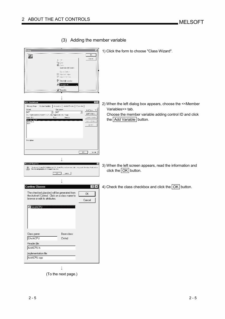
1) Click the form to choose "Class Wizard".
2) When the left dialog box appears, choose the <<Member Variables>> tab. Choose the member variable adding control ID and click the Add Variable button.
3) When the left screen appears, read the information and click the OK button.
4) Check the class checkbox and click the OK button.
(To the next page.)
2 - 6 2 - 6
MELSOFT2 ABOUT THE ACT CONTROLS
(From the previous page)
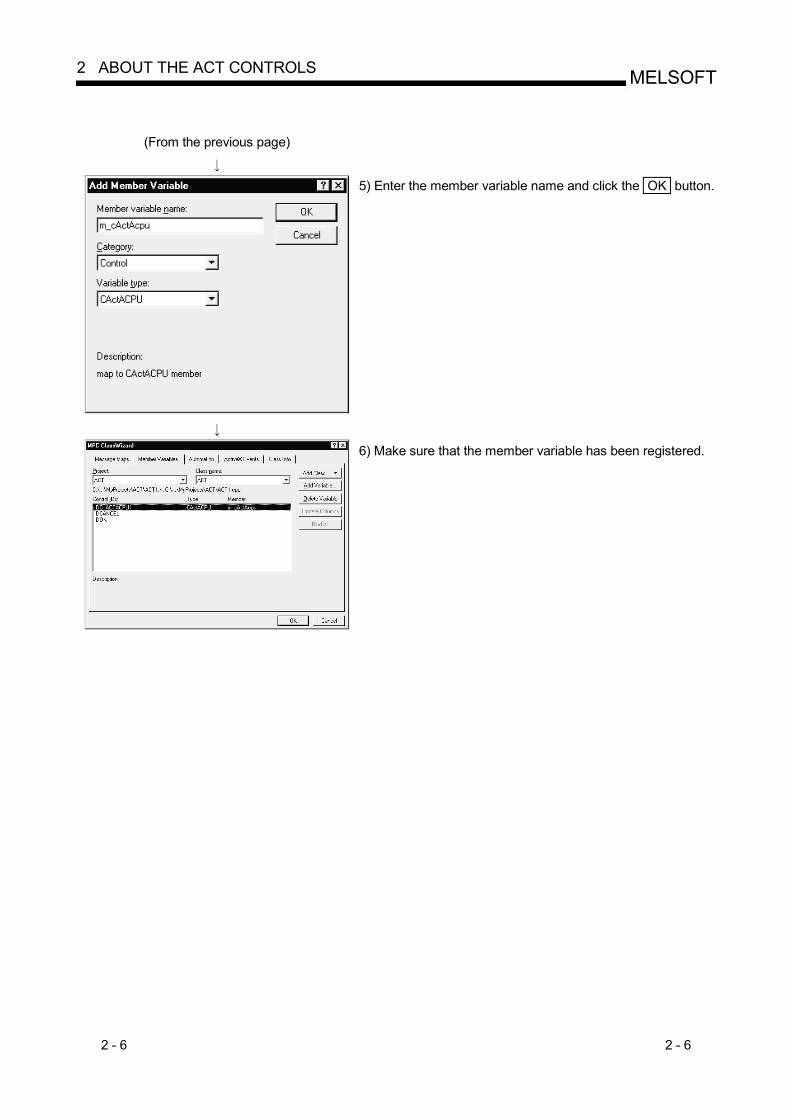
5) Enter the member variable name and click the OK button.
6) Make sure that the member variable has been registered.
2 - 7 2 - 7
MELSOFT2 ABOUT THE ACT CONTROLS
2.1.3 When using VBA
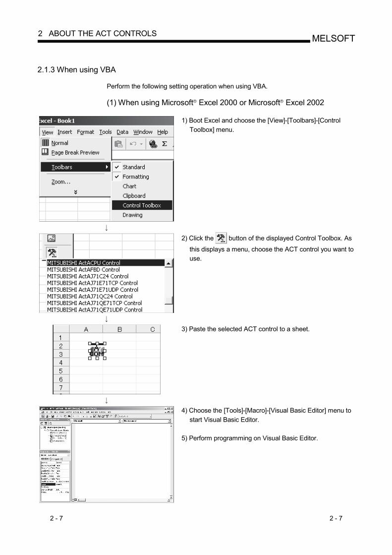
Perform the following setting operation when using VBA. (1) When using Microsoft R Excel 2000 or Microsoft R Excel 2002
1) Boot Excel and choose the [View]-[Toolbars]-[Control Toolbox] menu.
2) Click the button of the displayed Control Toolbox. As
this displays a menu, choose the ACT control you want to use.
3) Paste the selected ACT control to a sheet.
4) Choose the [Tools]-[Macro]-[Visual Basic Editor] menu to start Visual Basic Editor.
5) Perform programming on Visual Basic Editor.

2 - 8 2 - 8
MELSOFT2 ABOUT THE ACT CONTROLS
(2) When using Microsoft R Access 2000 or Microsoft R Access 2002
1) Boot Access and make the database form active.
2) Click the button of the toolbox. As this displays a
menu, choose the ACT control you want to use.
3) Paste the selected ACT control to a sheet.
4) Choose the [Tools]-[Macro]-[Visual Basic Editor] menu to start Visual Basic Editor.
5) Perform programming on Visual Basic Editor.
2.1.4 When using VBScript
Create HTML or ASP using the notepad, commercially available text editor, HTML creation tool or like. Refer to the commercially available references and so on for the grammars of HTML and ASP. Also refer to the HTML and ASP sample programs installed in MX Component.

2 - 9 2 - 9
MELSOFT2 ABOUT THE ACT CONTROLS
2.1.5 When Using Visual Studio R .NET
Perform the following setting operation when using Visual Studio R .NET.
(1) Setting the include file (for Visual Basic R .NET)
1) Start the project and choose the [Project] - [Add Existing Item] menu.
2) Refer to the ActDefine.vb file and click the Open button.At the time of installation, the ActDefine.vb file is in <User-specified folder>-<Act>-<Include>.
3) The "ActDefine.vb" file appears in the Solution Explorer window.
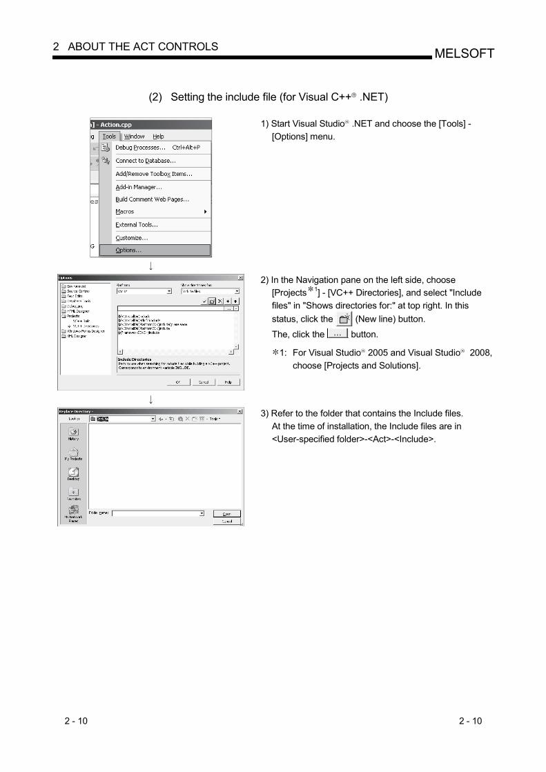
2 - 10 2 - 10
MELSOFT2 ABOUT THE ACT CONTROLS
(2) Setting the include file (for Visual C++ R .NET)
1) Start Visual Studio R .NET and choose the [Tools] - [Options] menu.
2) In the Navigation pane on the left side, choose [Projects 1] - [VC++ Directories], and select "Include files" in "Shows directories for:" at top right. In this status, click the (New line) button.
The, click the button.
1: For Visual Studio R 2005 and Visual Studio R 2008, choose [Projects and Solutions].
3) Refer to the folder that contains the Include files. At the time of installation, the Include files are in <User-specified folder>-<Act>-<Include>.

2 - 11 2 - 11
MELSOFT2 ABOUT THE ACT CONTROLS
(3) When pasting ACT control to form for use
(Common to Visual C++ R .NET and Visual Basic R .NET projects)
1) Choose the [Tools] - [Add/Remove Toolbox Items 2] menu.
2: For Visual Studio R 2005 and Visual Studio R 2008, choose [Choose Toolbox Items].
2) Choose the <<COM Components>> tab, check the ACT control to be used, and click the OK button.
3) The ACT control is added to the bottom of the tab selected in "Toolbox".

2 - 12 2 - 12
MELSOFT2 ABOUT THE ACT CONTROLS
(4) When using ACT control without pasting it to a form (Reference)
(Common to Visual Studio R .NET 2003 projects)
1) Choose [View] - [Solution Explorer] menu to display "Solution Explorer", and right-click "Reference" to select "Add Reference".
2) Choose the <<COM>> tab and select the ACT control to be used. In this state, click the Select button. By keepping the [Ctrl] key pressed, multiple ACT controls can be selected simultaneously.
3) When all the components to be used are displayed in "Selected Components", click the OK button.
4) The library of the components used for "Solution Explorer" is set to Reference.
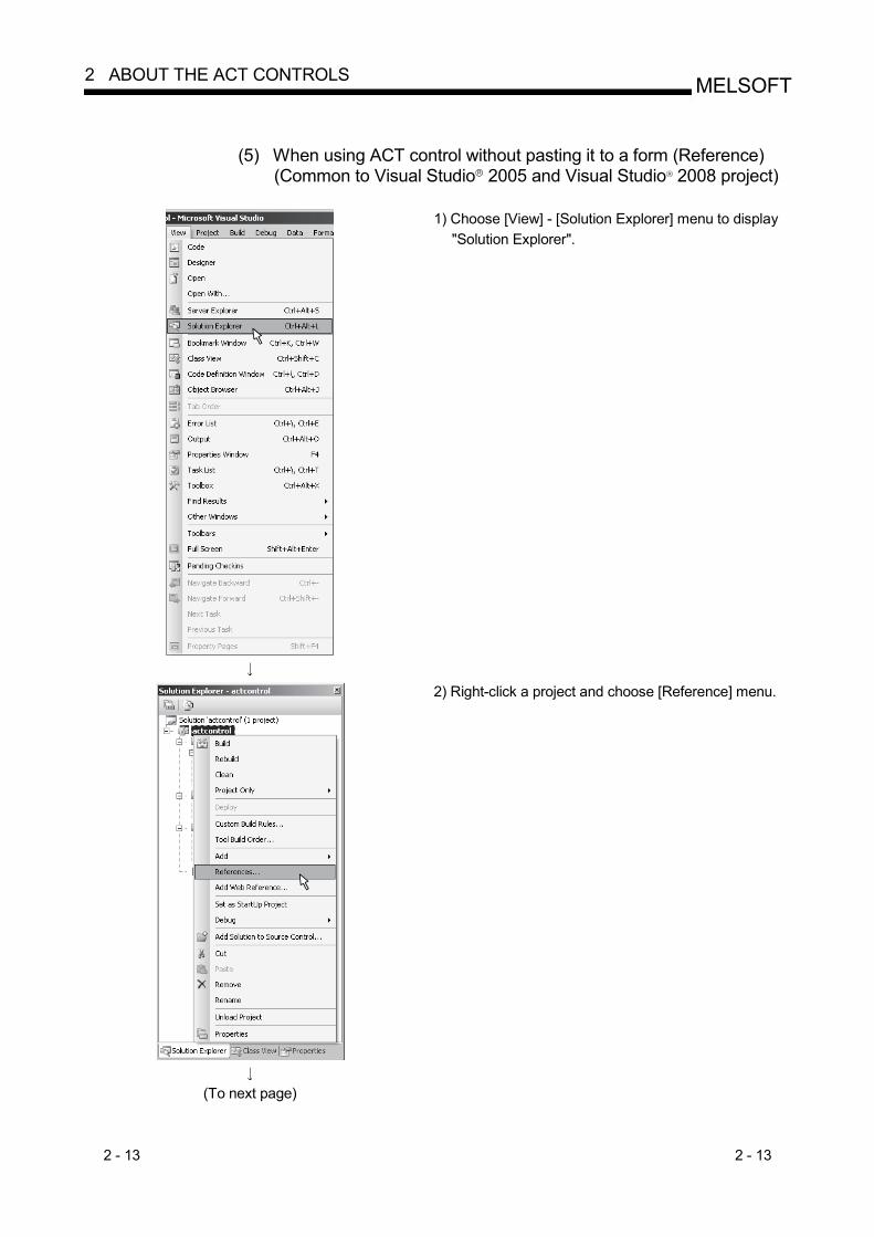
2 - 13 2 - 13
MELSOFT2 ABOUT THE ACT CONTROLS
(5) When using ACT control without pasting it to a form (Reference)
(Common to Visual Studio R 2005 and Visual Studio R 2008 project)
1) Choose [View] - [Solution Explorer] menu to display "Solution Explorer".
(To next page)
2) Right-click a project and choose [Reference] menu.

2 - 14 2 - 14
MELSOFT2 ABOUT THE ACT CONTROLS
(From previous page)
3) Click the Add New Reference… button. (The figure is in Visual Studio R 2008.)
(To next page)
4) Choose the <<COM>> tab and click the OK button while ACT control to be used is selected.

2 - 15 2 - 15
MELSOFT2 ABOUT THE ACT CONTROLS
(From previous page)
5) The library of the component to be used for "References:" is set to "References". (The figure is in Visual Studio R 2008.)
The library of the component to be used can be checked in "References" on "Class View". (In Visual Studio R 2008, enable "Show Project Reference" in the "Class View Settings".)
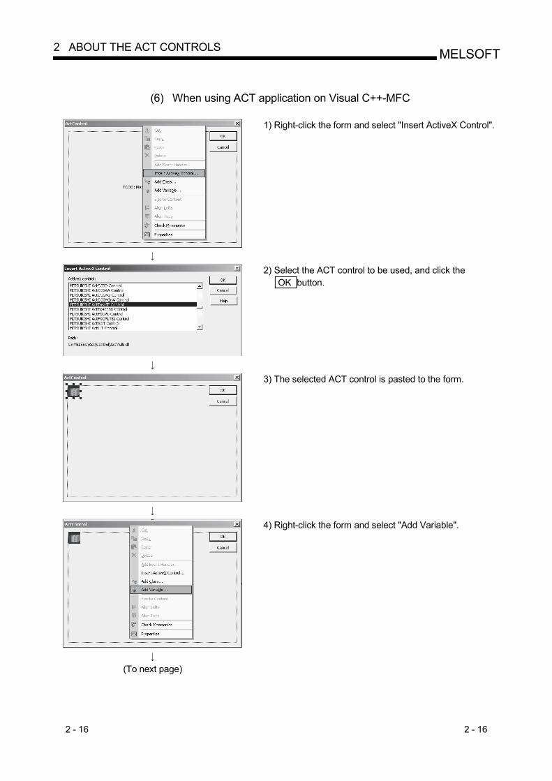
2 - 16 2 - 16
MELSOFT2 ABOUT THE ACT CONTROLS
(6) When using ACT application on Visual C++-MFC
1) Right-click the form and select "Insert ActiveX Control".
2) Select the ACT control to be used, and click the OK button.
3) The selected ACT control is pasted to the form.
(To next page)
4) Right-click the form and select "Add Variable".

2 - 17 2 - 17
MELSOFT2 ABOUT THE ACT CONTROLS
(From previous page)
5) After checking "Control variable", select the ID of the ACT control in "Control ID", enter the variable name, and click the Finish button.
6) Make sure that the member variable set in Step 5) has been created.
• In form class of Class View • In header file of form class
<The figure is in Visual Studio R 2005.>
<The figure is in Visual Studio R 2008.>

2 - 18 2 - 18
MELSOFT2 ABOUT THE ACT CONTROLS
2.2 Programming Procedures
This section gives the procedures of creating a user application. 2.2.1 When using Visual Basic R 6.0 or Visual Basic R .NET
When using Visual Basic R 6.0 or Visual Basic R .NET, create a user application in the following procedure.
Make settings using the utility setting type?
Yes
No
<Utility setting type>
Start the communication settings utility and make communication settings in accordance with the wizard.
Refer to theoperating manual.
<Program setting type>
Create a form and paste the ACT controls for corresponding communication.
Set the properties of the pasted ACT controls.
Refer to Section 2.1.1andSection 2.1.5.
Perform programming using the functions offered by the corresponding ACT control.
Refer to the operating manual.
Perform debugging usingthe PLC monitor utility?
No
Yes
Completion of user application
Create a form and paste the ACT control to the form. (ActEasyIF control)
Set the property of the pasted control. (Set only the logical station number)
Refer to Section 2.1.1andSection 2.1.5.
Refer to the operating manual.
Refer to the operating manual.
Refer to the operating manual (startup).Install MX Component.
Power on the IBM-PC/AT compatible and start Windows .
Register the ACT control to Visual Basic 6.0 or Visual Basic .NET.
Refer to Chapters 3, 4.
Add the ACT controls to Visual Basic 6.0 or Visual Basic .NET.
Start Visual Basic 6.0 or Visual Basic .NET.
Start Visual Basic 6.0 or Visual Basic .NET.

2 - 19 2 - 19
MELSOFT2 ABOUT THE ACT CONTROLS
2.2.2 When using Visual C++ R 6.0 or Visual C++ R .NET
When using Visual C++ R 6.0 or Visual C++ R .NET, create a user application in the following procedure.
Make settings using the utility setting type?
Yes
No
<Utility setting type>
Start the communication settings utility and make communication settings in accordance with the wizard.
Refer to the operating manual.
<Program setting type>
Refer to the operating manual (startup).Install MX Component.
Power on the IBM-PC/AT compatible and start Windows .
Create a form and paste the ACT control for corresponding communication.
Set the properties of the pasted ACT control.
Refer to Section 2.1.2andSection 2.1.5.
Perform programming using the functions offered by the corresponding ACT control.
Refer to the operating manual.
Perform debugging using the PLC monitor utility?
No
Yes
Completion of user application
Using Class Wizard, define the pasted ACT control as a dialog member.Create a form and paste the ACT
control to the form. (ActEasyIF control)
Set the property of the pasted control. (Set only the logical station number)
Refer to Section 2.1.2andSection 2.1.5.
Using Class Wizard, define the pasted ACT control as a dialog member.
Refer to the operating manual.
Refer to the operating manual.
Refer to Chapters 3, 4.
Start Visual C++ 6.0 or Visual C++ .NET.
Register the ACT control to Visual C++ 6.0 or Visual C++ .NET.
Start Visual C++ 6.0 or Visual C++ .NET.
Add the ACT control to Visual C++ 6.0 or Visual C++ .NET.

2 - 20 2 - 20
MELSOFT2 ABOUT THE ACT CONTROLS
2.2.3 When using VBA
When using VBA, create a user application in the following procedure.
Make settings using the utility setting type?
Yes
No
<Utility setting type>
Start the communication settings utility and make communication settings in accordance with the wizard.
Refer to the operating manual.
<Program setting type>
Set the properties of the pasted ACT control.
Perform programming using the functions offered by the corresponding ACT control.
Refer to the operating manual.
Perform debugging using the PLC monitor utility?
No
Yes
Completion of user application
Set the property of the pasted control. (Set only the logical station number)
Refer to Section 2.1.3.
Refer to the operating manual.
Refer to the operating manual.
Refer to the operating manual (startup).Install MX Component.
Power on the IBM-PC/AT compatible and start Windows .
Refer to Chapters 3, 4.
Start Excel or Access.
Start Visual Basic Editor and createapplications.
Generate the ActEasyIF control so thatMX Component may be utilized on VBA.
Refer to Section 2.1.3.
Start Excel or Access.
Start Visual Basic Editor and createapplications.
Generate the correspondingcommunication control so that MXComponent may be utilized on VBA.
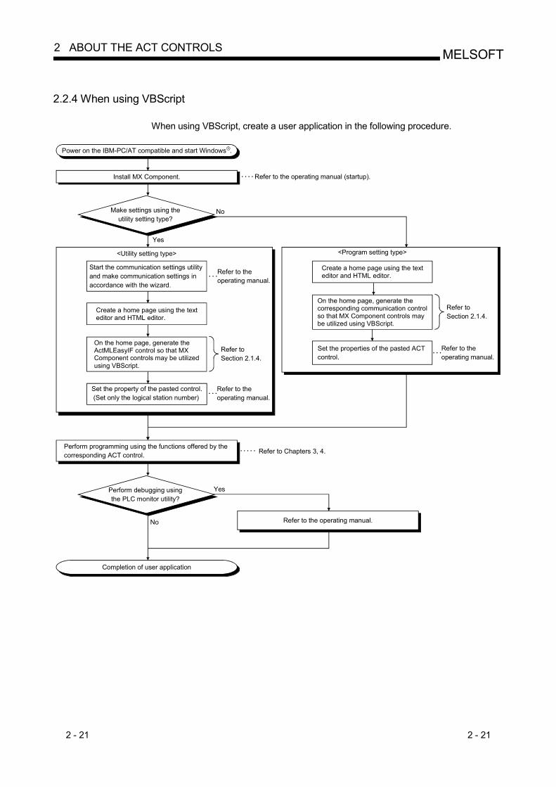
2 - 21 2 - 21
MELSOFT2 ABOUT THE ACT CONTROLS
2.2.4 When using VBScript
When using VBScript, create a user application in the following procedure.
Make settings using the utility setting type?
Yes
No
<Utility setting type>
Start the communication settings utility and make communication settings in accordance with the wizard.
Refer to the operating manual.
<Program setting type>
Perform programming using the functions offered by the corresponding ACT control.
Refer to the operating manual.
Perform debugging using the PLC monitor utility?
No
Yes
Completion of user application
Set the property of the pasted control. (Set only the logical station number)
Refer to Section 2.1.4.
Refer to the operating manual.
Refer to the operating manual (startup).Install MX Component.
Power on the IBM-PC/AT compatible and start Windows .
Refer to Chapters 3, 4.
Create a home page using the texteditor and HTML editor.
On the home page, generate theActMLEasyIF control so that MXComponent controls may be utilizedusing VBScript.
Set the properties of the pasted ACT control.
Refer to the operating manual.
Refer to Section 2.1.4.
Create a home page using the texteditor and HTML editor.
On the home page, generate thecorresponding communication controlso that MX Component controls maybe utilized using VBScript.
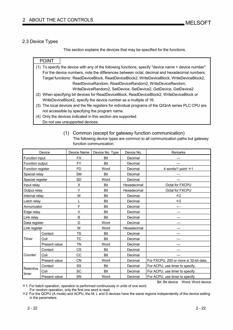
2 - 22 2 - 22
MELSOFT2 ABOUT THE ACT CONTROLS
2.3 Device Types
This section explains the devices that may be specified for the functions.
POINT (1) To specify the device with any of the following functions, specify "device name + device number".
For the device numbers, note the differences between octal, decimal and hexadecimal numbers. Target functions: ReadDeviceBlock, ReadDeviceBlock2, WriteDeviceBlock, WriteDeviceBlock2,
ReadDeviceRandom, ReadDeviceRandom2, WriteDeviceRandom, WriteDeviceRandom2, SetDevice, SetDevice2, GetDevice, GetDevice2
(2) When specifying bit devices for ReadDeviceBlock, ReadDeviceBlock2, WriteDeviceBlock or WriteDeviceBlock2, specify the device number as a multiple of 16.
(3) The local devices and the file registers for individual programs of the Q/QnA series PLC CPU are not accessible by specifying the program name.
(4) Only the devices indicated in this section are supported. Do not use unsupported devices.
(1) Common (except for gateway function communication)
The following device types are common to all communication paths but gateway function communication.
Device Device Name Device No. Type Device No. Remarks
Function input FX Bit Decimal — Function output FY Bit Decimal — Function register FD Word Decimal 4 words/1 point 1 Special relay SM Bit Decimal — Special register SD Word Decimal — Input relay X Bit Hexadecimal Octal for FXCPU Output relay Y Bit Hexadecimal Octal for FXCPU Internal relay M Bit Decimal 2 Latch relay L Bit Decimal 2 Annunciator F Bit Decimal — Edge relay V Bit Decimal — Link relay B Bit Decimal — Data register D Word Decimal — Link register W Word Hexadecimal —
Contact TS Bit Decimal — Coil TC Bit Decimal — Timer Present value TN Word Decimal — Contact CS Bit Decimal — Coil CC Bit Decimal — Counter Present value CN Word Decimal For FXCPU, 200 or more is 32-bit data. Contact SS Bit Decimal For ACPU, use timer to specify. Coil SC Bit Decimal For ACPU, use timer to specify.
Retentive timer
Present value SN Word Decimal For ACPU, use timer to specify. Bit: Bit device Word: Word device
1: For batch operation, operation is performed continuously in units of one word. For random operation, only the first one word is read.
2: For the QCPU (A mode) and ACPU, the M, L and S devices have the same regions independently of the device setting in the parameters.
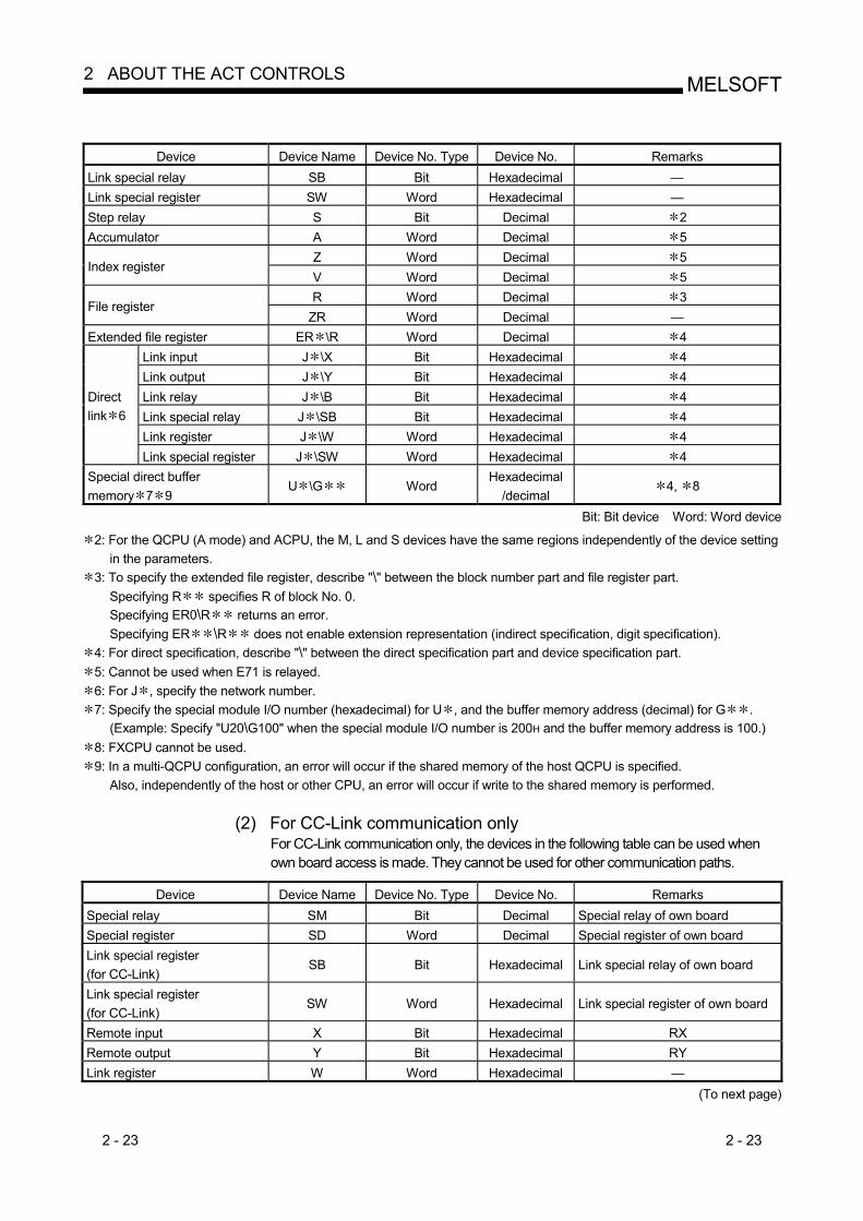
2 - 23 2 - 23
MELSOFT2 ABOUT THE ACT CONTROLS
Device Device Name Device No. Type Device No. Remarks
Link special relay SB Bit Hexadecimal — Link special register SW Word Hexadecimal — Step relay S Bit Decimal 2 Accumulator A Word Decimal 5
Z Word Decimal 5 Index register
V Word Decimal 5 R Word Decimal 3
File register ZR Word Decimal —
Extended file register ER \R Word Decimal 4 Link input J \X Bit Hexadecimal 4 Link output J \Y Bit Hexadecimal 4 Link relay J \B Bit Hexadecimal 4 Link special relay J \SB Bit Hexadecimal 4 Link register J \W Word Hexadecimal 4
Direct link 6
Link special register J \SW Word Hexadecimal 4 Special direct buffer memory 7 9
U \G Word Hexadecimal
/decimal 4, 8
Bit: Bit device Word: Word device
2: For the QCPU (A mode) and ACPU, the M, L and S devices have the same regions independently of the device setting in the parameters.
3: To specify the extended file register, describe "\" between the block number part and file register part. Specifying R specifies R of block No. 0. Specifying ER0\R returns an error. Specifying ER \R does not enable extension representation (indirect specification, digit specification).
4: For direct specification, describe "\" between the direct specification part and device specification part. 5: Cannot be used when E71 is relayed. 6: For J , specify the network number. 7: Specify the special module I/O number (hexadecimal) for U , and the buffer memory address (decimal) for G .
(Example: Specify "U20\G100" when the special module I/O number is 200H and the buffer memory address is 100.) 8: FXCPU cannot be used. 9: In a multi-QCPU configuration, an error will occur if the shared memory of the host QCPU is specified.
Also, independently of the host or other CPU, an error will occur if write to the shared memory is performed.
(2) For CC-Link communication only For CC-Link communication only, the devices in the following table can be used when own board access is made. They cannot be used for other communication paths.
Device Device Name Device No. Type Device No. Remarks
Special relay SM Bit Decimal Special relay of own board Special register SD Word Decimal Special register of own board Link special register (for CC-Link)
SB Bit Hexadecimal Link special relay of own board
Link special register (for CC-Link)
SW Word Hexadecimal Link special register of own board
Remote input X Bit Hexadecimal RX Remote output Y Bit Hexadecimal RY Link register W Word Hexadecimal —
(To next page)

2 - 24 2 - 24
MELSOFT2 ABOUT THE ACT CONTROLS
Device Device Name Device No. Type Device No. Remarks
Remote register (write area for CC-Link)
WW Word Hexadecimal RWw
Remote register (read area for CC-Link)
WR Word Hexadecimal RWr
Buffer memory ML Word Hexadecimal Buffer memory of own station CC-Link module
Random access buffer MC Word Hexadecimal Random access buffer in buffer memory of own station CC-Link module
Automatic refresh buffer MF Bit Hexadecimal Automatic refresh buffer of own station CC-Link module
(3) For gateway function communication only
This section gives how to specify the device name used for gateway function communication. For the way to specify the devices used in the methods of the other controls, refer to the MX Component Operating Manual.
Device Device Name Device No. Type Device No. Remarks
Gateway device 1 EG Word Decimal —
1: If data is read from the gateway device where the PLC CPU device has not been assigned, the read data is 0.
(4) About device extension representation The device extension representation usability table is given below. They cannot be used with ReadDeviceBlock and WriteDeviceBlock. When the ActAJ71E71TCP, ActMLAJ71E71TCP, ActAJ71QE71TCP or ActMLAJ71QE71TCP control is used, device expansion representation is unusable.
Target CPU
Device Extension Representation QCPU
(Q mode) QSCPU
QCPU (A mode)
QnACPU ACPU FXCPU Motion controller CPU GOT
Digit specification (example: K4M0) 2
Bit specification (example: D0.1)
3 3 3 3 3 3 3
Index qualification (example: M100Z0) 4 1
: Usable : Unusable 1: Unusable when QE71 is relayed. 2: FX/FX, DX/DY and T/C/ST (contact, coil) cannot be specified. 3: Z, V, T/C/ST (present value) cannot be specified. 4: FX/FX, DX/DY, T/C/ST (contact, coil), Z and S cannot be specified.
2.4 Accessible Devices and Ranges
Refer to the MX Component operating manual for the accessible devices and ranges for corresponding communication.
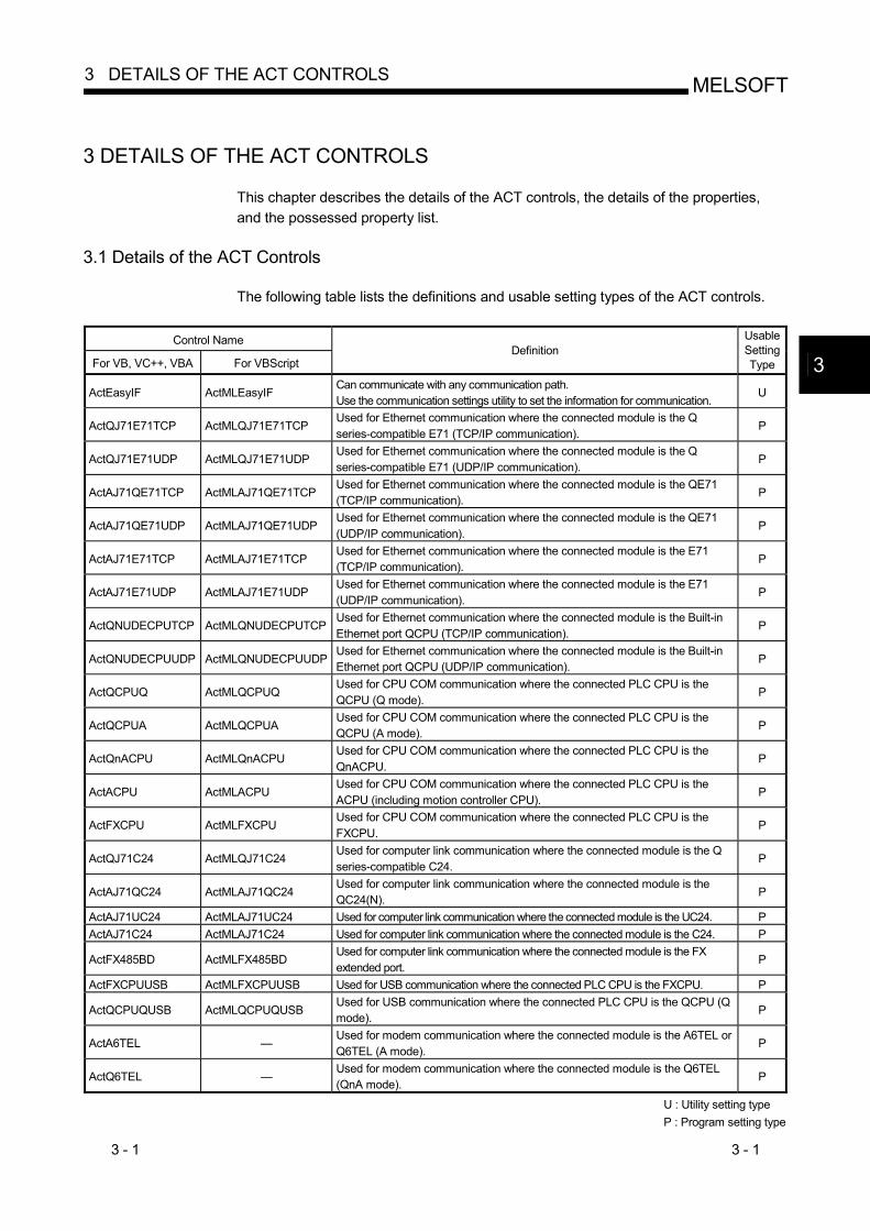
3 - 1 3 - 1
MELSOFT3 DETAILS OF THE ACT CONTROLS
3 DETAILS OF THE ACT CONTROLS
This chapter describes the details of the ACT controls, the details of the properties, and the possessed property list.
3.1 Details of the ACT Controls
The following table lists the definitions and usable setting types of the ACT controls.
Control Name
For VB, VC++, VBA For VBScript Definition
UsableSettingType
ActEasyIF ActMLEasyIF Can communicate with any communication path. Use the communication settings utility to set the information for communication.
U
ActQJ71E71TCP ActMLQJ71E71TCP Used for Ethernet communication where the connected module is the Q series-compatible E71 (TCP/IP communication).
P
ActQJ71E71UDP ActMLQJ71E71UDP Used for Ethernet communication where the connected module is the Q series-compatible E71 (UDP/IP communication).
P
ActAJ71QE71TCP ActMLAJ71QE71TCP Used for Ethernet communication where the connected module is the QE71 (TCP/IP communication).
P
ActAJ71QE71UDP ActMLAJ71QE71UDP Used for Ethernet communication where the connected module is the QE71 (UDP/IP communication).
P
ActAJ71E71TCP ActMLAJ71E71TCP Used for Ethernet communication where the connected module is the E71 (TCP/IP communication).
P
ActAJ71E71UDP ActMLAJ71E71UDP Used for Ethernet communication where the connected module is the E71 (UDP/IP communication).
P
ActQNUDECPUTCP ActMLQNUDECPUTCP Used for Ethernet communication where the connected module is the Built-in Ethernet port QCPU (TCP/IP communication).
P
ActQNUDECPUUDP ActMLQNUDECPUUDP Used for Ethernet communication where the connected module is the Built-in Ethernet port QCPU (UDP/IP communication).
P
ActQCPUQ ActMLQCPUQ Used for CPU COM communication where the connected PLC CPU is the QCPU (Q mode).
P
ActQCPUA ActMLQCPUA Used for CPU COM communication where the connected PLC CPU is the QCPU (A mode).
P
ActQnACPU ActMLQnACPU Used for CPU COM communication where the connected PLC CPU is the QnACPU.
P
ActACPU ActMLACPU Used for CPU COM communication where the connected PLC CPU is the ACPU (including motion controller CPU).
P
ActFXCPU ActMLFXCPU Used for CPU COM communication where the connected PLC CPU is the FXCPU.
P
ActQJ71C24 ActMLQJ71C24 Used for computer link communication where the connected module is the Q series-compatible C24.
P
ActAJ71QC24 ActMLAJ71QC24 Used for computer link communication where the connected module is the QC24(N).
P
ActAJ71UC24 ActMLAJ71UC24 Used for computer link communication where the connected module is the UC24. P ActAJ71C24 ActMLAJ71C24 Used for computer link communication where the connected module is the C24. P
ActFX485BD ActMLFX485BD Used for computer link communication where the connected module is the FX extended port.
P
ActFXCPUUSB ActMLFXCPUUSB Used for USB communication where the connected PLC CPU is the FXCPU. P
ActQCPUQUSB ActMLQCPUQUSB Used for USB communication where the connected PLC CPU is the QCPU (Q mode).
P
ActA6TEL — Used for modem communication where the connected module is the A6TEL or Q6TEL (A mode).
P
ActQ6TEL — Used for modem communication where the connected module is the Q6TEL (QnA mode).
P
U : Utility setting type P : Program setting type
3
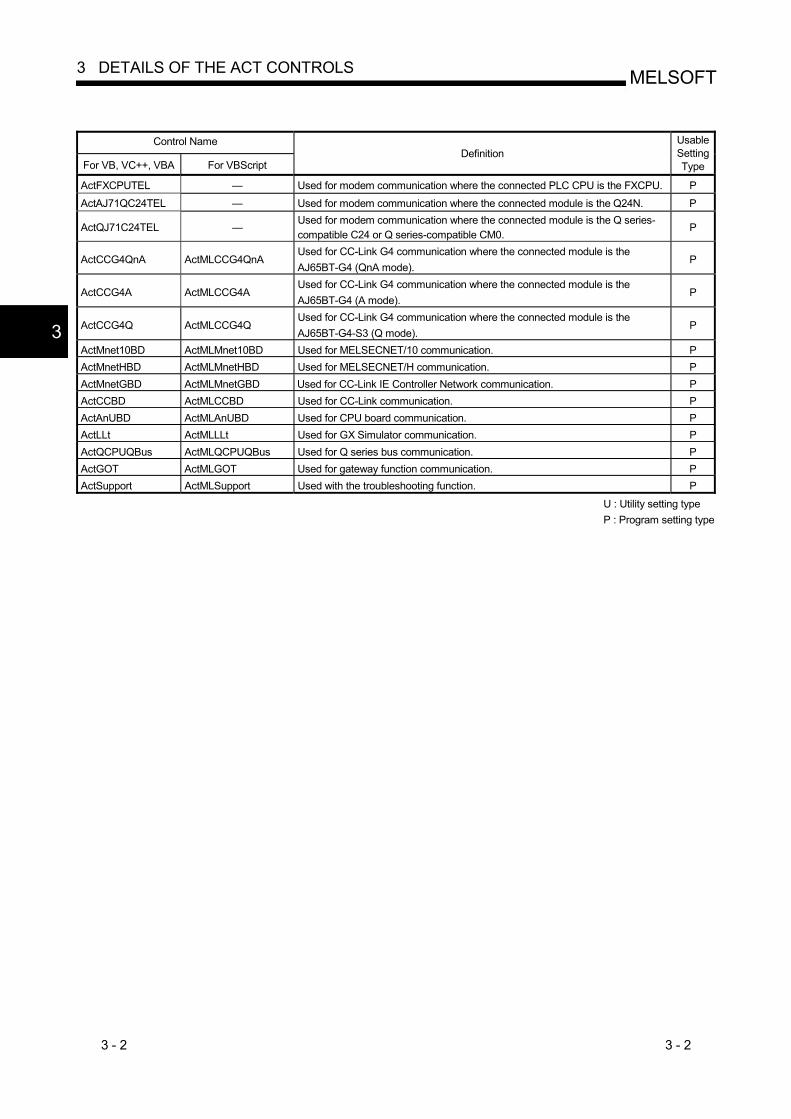
3 - 2 3 - 2
MELSOFT3 DETAILS OF THE ACT CONTROLS
Control Name
For VB, VC++, VBA For VBScript Definition
UsableSettingType
ActFXCPUTEL — Used for modem communication where the connected PLC CPU is the FXCPU. P
ActAJ71QC24TEL — Used for modem communication where the connected module is the Q24N. P
ActQJ71C24TEL — Used for modem communication where the connected module is the Q series-compatible C24 or Q series-compatible CM0.
P
ActCCG4QnA ActMLCCG4QnA Used for CC-Link G4 communication where the connected module is the AJ65BT-G4 (QnA mode).
P
ActCCG4A ActMLCCG4A Used for CC-Link G4 communication where the connected module is the AJ65BT-G4 (A mode).
P
ActCCG4Q ActMLCCG4Q Used for CC-Link G4 communication where the connected module is the AJ65BT-G4-S3 (Q mode).
P
ActMnet10BD ActMLMnet10BD Used for MELSECNET/10 communication. P ActMnetHBD ActMLMnetHBD Used for MELSECNET/H communication. P ActMnetGBD ActMLMnetGBD Used for CC-Link IE Controller Network communication. P ActCCBD ActMLCCBD Used for CC-Link communication. P ActAnUBD ActMLAnUBD Used for CPU board communication. P ActLLt ActMLLLt Used for GX Simulator communication. P ActQCPUQBus ActMLQCPUQBus Used for Q series bus communication. P ActGOT ActMLGOT Used for gateway function communication. P ActSupport ActMLSupport Used with the troubleshooting function. P
U : Utility setting type P : Program setting type
3

3 - 3 3 - 3
MELSOFT3 DETAILS OF THE ACT CONTROLS
3.2 Details of the Properties
The following tables give the details of the properties which must be set to create a user application.
POINT When entering a property value directly into the property window of Visual Basic R 6.0 or Visual C++ R 6.0, change a character string such as a hexadecimal number or CPU type into a decimal property value.
Property Name (Type) Description
ActLogicalStationNumber (LONG)
Logical station number set on the communication settings utility. (Setting range: 0 to 1023)
Specify the network number on the MELSECNET/10(H). (Specify "0x00" when specifying the own station.) Specify the network number for accessing other station by GX Simulator. Specify as follows for multidrop connection (via Q series-compatible C24, QJ61BT11).
ActIntelligentPreferenceBit value Description 0x00 Specify the own network. 0x01 Specify another network of multidrop destination.
ActNetworkNumber (LONG)
Specify the station number for MELSECNET/10(H) or CC-Link. (Specify "0x00" when specifying the own station.) Specify the station number for accessing other station by GX Simulator. Handled as the own station when access to the CPU of the CPU board is made. Specify as follows for multidrop connection (via Q series-compatible C24, QJ61BT11).
ActIntelligentPreferenceBit value Description 0x00 Specify the own network. 0x01 Specify another network of multidrop destination.
ActStationNumber (LONG)
ActUnitNumber (LONG)
Specify the module number of the computer link module or the station number when the target is the Q series-compatible intelligent special function module. However, specify "00x0" when setting the QnA series own station (module loaded to the own station CPU). Invalid when the target is not the computer link communication or Q series-compatible intelligent special function module. For multidrop link, specify the module number of the target computer link module.
ActConnectUnitNumber (LONG)
Specify the module number of the computer link module, QE71 or Q series-compatible E71. For multidrop link, specify the module number of the requesting computer link module. For multidrop link via CPU COM communication, however, the module number of the requesting station is not needed (specify "00x0"). Specify "0x00" for other than multidrop link. For the QE71 and Q series-compatible E71, specify the relay target station number (fixed to "0x00" for access within the own network). For access to another network via MELSECNET/10, specify the station number set in the parameter of the connected Ethernet module.
ActIONumber (LONG)
Specify the module I/O number. For multidrop link or intelligent special function module access, specify the actual I/O number (first I/O number 16) of the target computer link module or intelligent special function module (specify the I/O number of the relayed or requesting station for multidrop link). Specify "0x3FF" when making access to another station via the own station CPU or network.

3 - 4 3 - 4
MELSOFT3 DETAILS OF THE ACT CONTROLS
Property Name
(Type) Description
ActCpuType (LONG)
Specify the target CPU to communicate with. In the parameter, specify any of the CPU types in the following table.
Property value (Property window input
value) Target CPU
Property value (Property window input
value) Target CPU
CPU_Q00JCPU (0x30) Q00JCPU CPU_Q00UJCPU (0x80) Q00UJCPU CPU_Q00CPU (0x31) Q00CPU
CPU_A2CCPU (0x107) A2CCPU, A2CCPUC24( PRF), A2CJCPU
CPU_Q00UCPU (0x81) Q00UCPU CPU_Q01CPU (0x32) Q01CPU
CPU_A2NCPU (0x108) A2NCPU( S1), A2SCPU( S1)
CPU_Q01UCPU (0x82) Q01UCPU CPU_A2SHCPU(0x109) A2SHCPU( S1) CPU_Q02CPU (0x22) Q02(H)CPU CPU_A3NCPU (0x10A) A3NCPU CPU_Q06CPU (0x23) Q06HCPU CPU_Q12CPU (0x24) Q12HCPU
CPU_A2ACPU (0x10C) A2ACPU( S1), A2ACPUP21/R21( S1)
CPU_Q25CPU (0x25) Q25HCPU CPU_Q02PHCPU(0x45) Q02PHCPU
CPU_A3ACPU (0x10D) A3ACPU, A3ACPUP21/R21
CPU_Q06PHCPU(0x46) Q06PHCPU CPU_Q12PHCPU (0x41) Q12PHCPU CPU_Q25PHCPU (0x42) Q25PHCPU
CPU_A2UCPU (0x10E) A2UCPU( S1), A2USCPU( S1), A2ASCPU( S1)
CPU_Q02CPU_A (0x141) Q02(H)CPU-A CPU_Q06CPU_A (0x142) Q06HCPU-A
CPU_A2USHS1CPU (0x10F)
A2USHCPU-S1CPU, CPU board
CPU_Q12PRHCPU (0x43) Q12PRHCPU CPU_Q25PRHCPU (0x44) Q25PRHCPU
CPU_A3UCPU (0x110) A3UCPU, A2ASCPU-S30
CPU_Q02UCPU(0x83) Q02UCPU CPU_A4UCPU (0x111) A4UCPU CPU_Q03UDCPU(0x70) Q03UDCPU CPU_FX0CPU (0x201) FX0CPU, FX0SCPU CPU_Q04UDHCPU(0x71) Q04UDHCPU CPU_FX0NCPU (0x202) FX0NCPU CPU_Q06UDHCPU(0x72) Q06UDHCPU CPU_FX1CPU (0x203) FX1CPU CPU_Q10UDHCPU(0x75) Q10UDHCPU CPU_FX2CPU (0x204) FX2CPU, FX2CCPU CPU_Q13UDHCPU(0x73) Q13UDHCPU CPU_FX2NCPU (0x205) FX2NCPU, FX2NCCPU CPU_Q20UDHCPU(0x76) Q20UDHCPU CPU_FX1SCPU (0x206) FX1SCPU CPU_Q26UDHCPU(0x74) Q26UDHCPU CPU_FX1NCPU (0x207) FX1NCPU, FX1NCCPU CPU_Q03UDECPU(0x90) Q03UDECPU CPU_FX3GCPU (0x209) FX3GCPU CPU_Q04UDEHCPU(0x91) Q04UDEHCPU CPU_FX3UCCPU (0x208) FX3UCPU, FX3UCCPU CPU_Q06UDEHCPU(0x92) Q06UDEHCPU CPU_A171SHCPU (0x601) A171SHCPU CPU_Q10UDEHCPU(0x95) Q10UDEHCPU CPU_A172SHCPU (0x602) A172SHCPU CPU_Q13UDEHCPU(0x93) Q13UDEHCPU CPU_A273UHCPU (0x603) A273UHCPU( S3) CPU_Q20UDEHCPU(0x96) Q20UDEHCPU CPU_A173UHCPU (0x604) A173UHCPU( S1) CPU_Q26UDEHCPU(0x94) Q26UDEHCPU CPU_BOARD (0x401) For own board access 1
CPU_QS001CPU(0x60) QS001CPU 1: Except CPU board CPU_Q2ACPU (0x11) Q2ACPU, Q2ASCPU,
Q2ASHCPU CPU_Q2AS1CPU (0x12)
Q2ACPU-S1, Q2ASCPU( S1), Q2ASHCPU( S1)
CPU_Q3ACPU (0x13) Q3ACPU CPU_Q4ACPU (0x14) Q4ACPU, Q4ARCPU CPU_A0J2HCPU (0x102) A0J2HCPU CPU_A1FXCPU (0x103) A1FXCPU
CPU_A1SCPU (0x104)
A1SCPU( S1), A1SCPUC24-R2, A1SJCPU
CPU_A1SHCPU (0x105) A1SHCPU, A1SJHCPU CPU_A1NCPU (0x106) A1NCPU

3 - 5 3 - 5
MELSOFT3 DETAILS OF THE ACT CONTROLS
Property Name(Type) Description
Specify the connection port number of the IBM-PC/AT compatible. When the Ethernet module is connected, set any value as the port number of the requesting source (IBM-PC/AT compatible). When "=0" was specified as the port number, the Station No. IP information system should be the automatic response system. (When the system selected is other than the automatic response system via QE71, you should set the fixed value "5001".) Also, when the control for network board is used, specify the first board as PORT_1, and the second and subsequent boards as PORT_2, PORT_3 ...
Property value (Property window input value)
Description
PORT_1 (0x01) Communication port 1 PORT_2 (0x02) Communication port 2 PORT_3 (0x03) Communication port 3 PORT_4 (0x04) Communication port 4 PORT_5 (0x05) Communication port 5 PORT_6 (0x06) Communication port 6 PORT_7 (0x07) Communication port 7 PORT_8 (0x08) Communication port 8 PORT_9 (0x09) Communication port 9 PORT_10 (0x0A) Communication port 10
ActPortNumber (LONG)
Specify the baudrate for computer link communication.
Property value (Property window input value)
Description Property value
(Property window input value) Description
BAUDRATE_300 (300)
300bps BAUDRATE_9600
(9600) 9600bps
BAUDRATE_600 (600)
600bps BAUDRATE_19200
(19200) 19200bps
BAUDRATE_1200 (1200)
1200bps BAUDRATE_38400
(38400) 38400bps
BAUDRATE_2400 (2400)
2400bps BAUDRATE_57600
(57600) 57600bps
BAUDRATE_4800 (4800)
4800bps BAUDRATE_115200
(115200) 115200bps
ActBaudRate (LONG)
ActDataBit(LONG) Specify the number of bits (7 or 8) of the byte data sent and received for computer link communication. Specify the parity system used for computer link communication.
Property value (Property window input value)
Description
NO_PARITY (0) No parity ODD_PARITY (1) Odd EVEN_PARITY (2) Even
ActParity (LONG)

3 - 6 3 - 6
MELSOFT3 DETAILS OF THE ACT CONTROLS
Property Name(Type) Description
Specify the number of stop bits used for computer link communication
Property value (Property window input value)
Description
STOPBIT_ONE (0) 1 stop bit STOPBITS_TWO (2) 2 stop bits
ActStopBit (LONG)
Specify the control setting of the signal line.
Property value (Property window input value)
Description
TRC_DTR (0x01) DTR control TRC_RTS (0x02) RTS control TRC_DRT_AND_RTS (0x07) DTR control and RTS control TRC_DTR_OR_RTS (0x08) DTR control or RTS control
ActControl (LONG)
ActHostAddress(BSTR) Pointer which indicates the connection host name (IP address) for Ethernet communication.
ActCpuTimeOut(LONG) Specify the CPU watchdog timer for Ethernet communication. (Unit = " 250ms") Specify the transmission waiting time for computer link communication of FX. (Unit = " 10ms")
ActTimeOut(LONG) Set the time-out value of communication between the IBM-PC/AT compatible and PLC. (Unit = "ms")MX Component may perform time-out processing internally depending on the communication path. For details, refer to "Appendix 3 About Time-Out Periods". Specify whether sumcheck is made or not. Valid only via computer link module.
Property value (Property window input value)
Description
NO_SUM_CHECK (0) Without sumcheck SUM_CHECK (1) With sumcheck
ActSumCheck (LONG)
ActSourceNetworkNumber (LONG)
Specify the requesting network number when the QE71 or Q series-compatible E71 is specified.Specify the same network number as for the connected QE71 or Q series-compatible E71 (network number specified in the network parameter).
ActSourceStationNumber (LONG)
Specify the requesting station number (IBM-PC/AT compatible side station number) when the QE71 or Q series-compatible E71 is specified. Make setting to avoid setting the same station number as that of the QE71 set within the same Ethernet loop. Specify the port number of the target when Ethernet communication is specified. For access to another network, specify the relay destination port number. For other than the automatic response system, make setting as indicated in the following table.
Communication Setting
QE71(UDP/IP) Fixed to "5001"
Other than Redundant PLC Fixed to "5002"
MELSOFT connection 1 Fixed to "5002"
Q series-compatible E71(TCP/IP)
OPS connection 1 Depending on network parameter
Q series-compatible E71(UDP/IP) Fixed to "5001"
1: For details, refer to the "Q Corresponding Ethernet Interface Module User's Manual (Basic)".
ActDestinationPort Number (LONG)
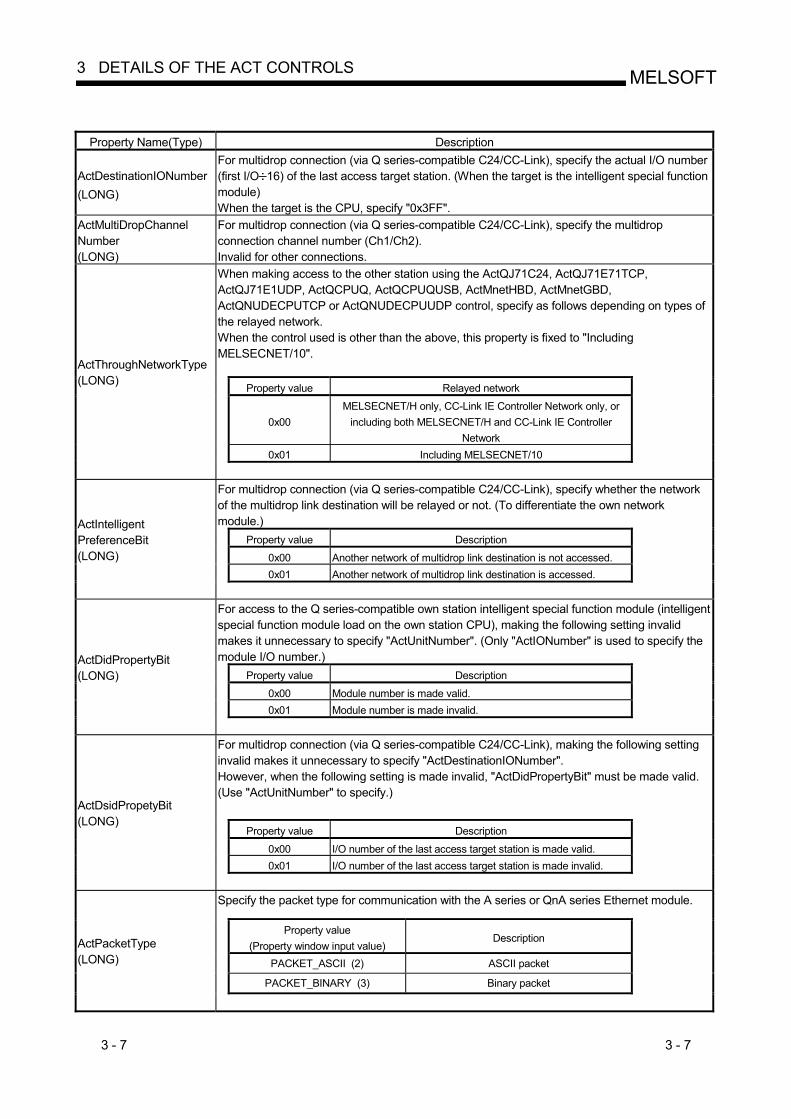
3 - 7 3 - 7
MELSOFT3 DETAILS OF THE ACT CONTROLS
Property Name(Type) Description
ActDestinationIONumber (LONG)
For multidrop connection (via Q series-compatible C24/CC-Link), specify the actual I/O number (first I/O 16) of the last access target station. (When the target is the intelligent special function module) When the target is the CPU, specify "0x3FF".
ActMultiDropChannel Number (LONG)
For multidrop connection (via Q series-compatible C24/CC-Link), specify the multidrop connection channel number (Ch1/Ch2). Invalid for other connections. When making access to the other station using the ActQJ71C24, ActQJ71E71TCP, ActQJ71E1UDP, ActQCPUQ, ActQCPUQUSB, ActMnetHBD, ActMnetGBD, ActQNUDECPUTCP or ActQNUDECPUUDP control, specify as follows depending on types of the relayed network. When the control used is other than the above, this property is fixed to "Including MELSECNET/10". Property value Relayed network
0x00 MELSECNET/H only, CC-Link IE Controller Network only, or
including both MELSECNET/H and CC-Link IE Controller Network
0x01 Including MELSECNET/10
ActThroughNetworkType (LONG)
For multidrop connection (via Q series-compatible C24/CC-Link), specify whether the network of the multidrop link destination will be relayed or not. (To differentiate the own network module.) Property value Description 0x00 Another network of multidrop link destination is not accessed. 0x01 Another network of multidrop link destination is accessed.
ActIntelligent PreferenceBit (LONG)
For access to the Q series-compatible own station intelligent special function module (intelligent special function module load on the own station CPU), making the following setting invalid makes it unnecessary to specify "ActUnitNumber". (Only "ActIONumber" is used to specify the module I/O number.) Property value Description 0x00 Module number is made valid. 0x01 Module number is made invalid.
ActDidPropertyBit (LONG)
For multidrop connection (via Q series-compatible C24/CC-Link), making the following setting invalid makes it unnecessary to specify "ActDestinationIONumber". However, when the following setting is made invalid, "ActDidPropertyBit" must be made valid. (Use "ActUnitNumber" to specify.)
Property value Description 0x00 I/O number of the last access target station is made valid. 0x01 I/O number of the last access target station is made invalid.
ActDsidPropetyBit (LONG)
Specify the packet type for communication with the A series or QnA series Ethernet module.
Property value (Property window input value)
Description
PACKET_ASCII (2) ASCII packet PACKET_BINARY (3) Binary packet
ActPacketType (LONG)

3 - 8 3 - 8
MELSOFT3 DETAILS OF THE ACT CONTROLS
Property Name(Type) Description
ActPassword (BSTR)
Specify a password to unlock the password lock set to a module that can be password locked such as the A6TEL, Q6TEL, Q series-compatible C24, Q series-compatible CMO, Q series-compatible E71 and Built-in Ethernet port QCPU. 1 2 If the characters specified are other than alphanumeric, a character code conversion error (0xF1000001) occurs at execution of Open. This setting is ignored when ActEasyIF or ActMLEasyIF control is used and a module that can be password locked is not used. Set the connection system. Property value
(Property window input value) Connection system 3
TEL_AUTO_CONNECT (0x00) Auto line connect TEL_AUTO_CALLBACK (0x01) Auto line connect (Callback fixation) TEL_AUTO_CALLBACK_NUMBER
(0x02) Auto line connect (Callback number specification)
TEL_CALLBACK (0x03) Callback connect (Fixation) TEL_CALLBACKNUMBER (0x04) Callback connect (Number specification) TEL_CALLBACK_REQUEST (0x05) Callback request (Fixation) TEL_CALLBACK_REQUEST_NUMBER
(0x06) Callback request (Number specification)
TEL_CALLBACK_WAIT (0x07) Callback reception waiting
ActConnectWay (LONG)
ActATCommand (BSTR)
Specify the AT command that initializes the modem. If you set no value (do not enter the property value), the modem-standard AT command is used. You can set up to 70 characters 2.
ActDialNumber (BSTR) Specify the telephone number. You can set up to 50 characters 2. (Characters that can be set: 0, 1, 2, 3, 4, 5, 6, 7, 8, 9, -, , #)
ActOutsideLineNumber (BSTR)
Specify the number to access the outside line. You can set up to 10 characters 2. (Characters that can be set: 0, 1, 2, 3, 4, 5, 6, 7, 8, 9, -, , #)
ActCallbackNumber (BSTR)
Specify the callback telephone number. You can set up to 62 characters 2. (Characters that can be set: 0, 1, 2, 3, 4, 5, 6, 7, 8, 9, -, , #) You need not set any value when the connection system (ActConnectWay) is other than auto line connect (callback number specification), callback connect (number specification) or callback request (number specification). Recognizes the line type. Property value
(Property window input value) Description
LINETYPE_PULSE (0x00)) Pulse (rotary dialing line) LINETYPE_TONE (0x01) Tone (pushbutton dialing line) LINETYPE_ISDN (0x02) ISDN (ISDN line)
ActLineType (LONG)
1: You need not set ActPassword if a password has not been set. 2: If the characters entered exceed the limit of set characters, the characters outside the setting range are ignored. 3: Only "Auto line connect" can be selected for the ActA6TEL, ActQ6TEL, ActFXCPUTEL and ActAJ71QC24TEL controls.
For details of the connection system for use of the ActAJ71QC24TEL control, refer to "Appendix 1 About the Connection System of the Callback Function".
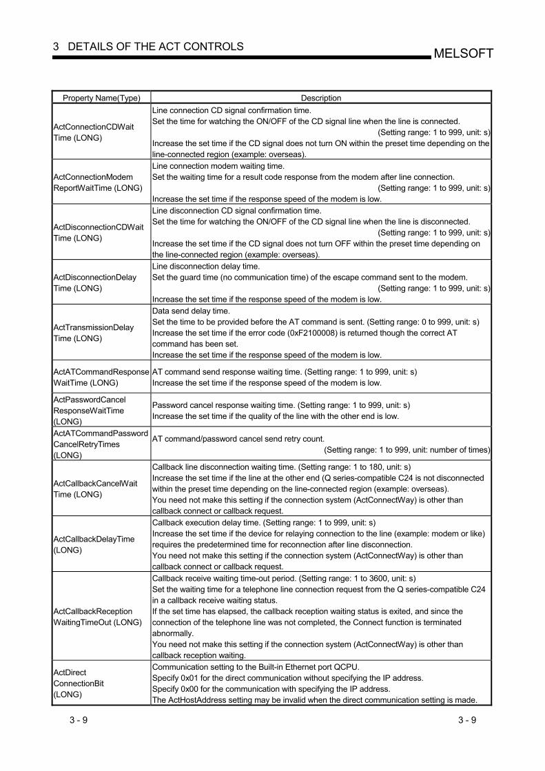
3 - 9 3 - 9
MELSOFT3 DETAILS OF THE ACT CONTROLS
Property Name(Type) Description
ActConnectionCDWait Time (LONG)
Line connection CD signal confirmation time. Set the time for watching the ON/OFF of the CD signal line when the line is connected.
(Setting range: 1 to 999, unit: s)Increase the set time if the CD signal does not turn ON within the preset time depending on the line-connected region (example: overseas).
ActConnectionModem ReportWaitTime (LONG)
Line connection modem waiting time. Set the waiting time for a result code response from the modem after line connection.
(Setting range: 1 to 999, unit: s)Increase the set time if the response speed of the modem is low.
ActDisconnectionCDWait Time (LONG)
Line disconnection CD signal confirmation time. Set the time for watching the ON/OFF of the CD signal line when the line is disconnected.
(Setting range: 1 to 999, unit: s)Increase the set time if the CD signal does not turn OFF within the preset time depending on the line-connected region (example: overseas).
ActDisconnectionDelay Time (LONG)
Line disconnection delay time. Set the guard time (no communication time) of the escape command sent to the modem.
(Setting range: 1 to 999, unit: s)Increase the set time if the response speed of the modem is low.
ActTransmissionDelay Time (LONG)
Data send delay time. Set the time to be provided before the AT command is sent. (Setting range: 0 to 999, unit: s) Increase the set time if the error code (0xF2100008) is returned though the correct AT command has been set. Increase the set time if the response speed of the modem is low.
ActATCommandResponse WaitTime (LONG)
AT command send response waiting time. (Setting range: 1 to 999, unit: s) Increase the set time if the response speed of the modem is low.
ActPasswordCancel ResponseWaitTime (LONG)
Password cancel response waiting time. (Setting range: 1 to 999, unit: s) Increase the set time if the quality of the line with the other end is low.
ActATCommandPasswordCancelRetryTimes (LONG)
AT command/password cancel send retry count. (Setting range: 1 to 999, unit: number of times)
ActCallbackCancelWait Time (LONG)
Callback line disconnection waiting time. (Setting range: 1 to 180, unit: s) Increase the set time if the line at the other end (Q series-compatible C24 is not disconnected within the preset time depending on the line-connected region (example: overseas). You need not make this setting if the connection system (ActConnectWay) is other than callback connect or callback request.
ActCallbackDelayTime (LONG)
Callback execution delay time. (Setting range: 1 to 999, unit: s) Increase the set time if the device for relaying connection to the line (example: modem or like) requires the predetermined time for reconnection after line disconnection. You need not make this setting if the connection system (ActConnectWay) is other than callback connect or callback request.
ActCallbackReception WaitingTimeOut (LONG)
Callback receive waiting time-out period. (Setting range: 1 to 3600, unit: s) Set the waiting time for a telephone line connection request from the Q series-compatible C24 in a callback receive waiting status. If the set time has elapsed, the callback reception waiting status is exited, and since the connection of the telephone line was not completed, the Connect function is terminated abnormally. You need not make this setting if the connection system (ActConnectWay) is other than callback reception waiting.
ActDirect ConnectionBit (LONG)
Communication setting to the Built-in Ethernet port QCPU. Specify 0x01 for the direct communication without specifying the IP address. Specify 0x00 for the communication with specifying the IP address. The ActHostAddress setting may be invalid when the direct communication setting is made.
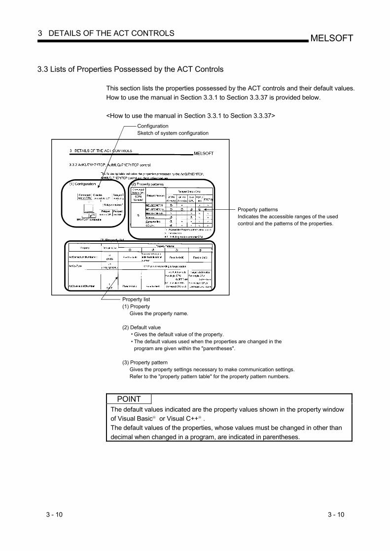
3 - 10 3 - 10
MELSOFT3 DETAILS OF THE ACT CONTROLS
3.3 Lists of Properties Possessed by the ACT Controls
This section lists the properties possessed by the ACT controls and their default values. How to use the manual in Section 3.3.1 to Section 3.3.37 is provided below.
<How to use the manual in Section 3.3.1 to Section 3.3.37>
ConfigurationSketch of system configuration
Property patternsIndicates the accessible ranges of the used control and the patterns of the properties.
Property list(1) Property Gives the property name.
(2) Default value Gives the default value of the property. The default values used when the properties are changed in the program are given within the "parentheses".
(3) Property pattern Gives the property settings necessary to make communication settings. Refer to the "property pattern table" for the property pattern numbers.
POINT
The default values indicated are the property values shown in the property window of Visual Basic R or Visual C++ R . The default values of the properties, whose values must be changed in other than decimal when changed in a program, are indicated in parentheses.

3 - 11 3 - 11
MELSOFT3 DETAILS OF THE ACT CONTROLS
3.3.1 ActEasyIF, ActMLEasyIF control
The following table indicates the property possessed by the ActEasyIF, ActMLEasyIF control and its default value.
Property Default Value Property Pattern
ActLogicalStationNumber 0 Logical station number set on the communication settings utility
ActPassword 1 Empty Password set to the A6TEL, Q6TEL, Q series-compatible C24, Q series-compatible E71 and Built-in Ethernet port QCPU on the connected station side
1: When you did not set the password, you need not set ActPassword.
POINT Depending on the communication path (Ethernet communication, MELSECNET/10 communication, etc.), there will be restrictions as placed on the corresponding communication path controls. For restrictions, refer to the corresponding communication path controls (Sections 3.3.2 to 3.3.37).
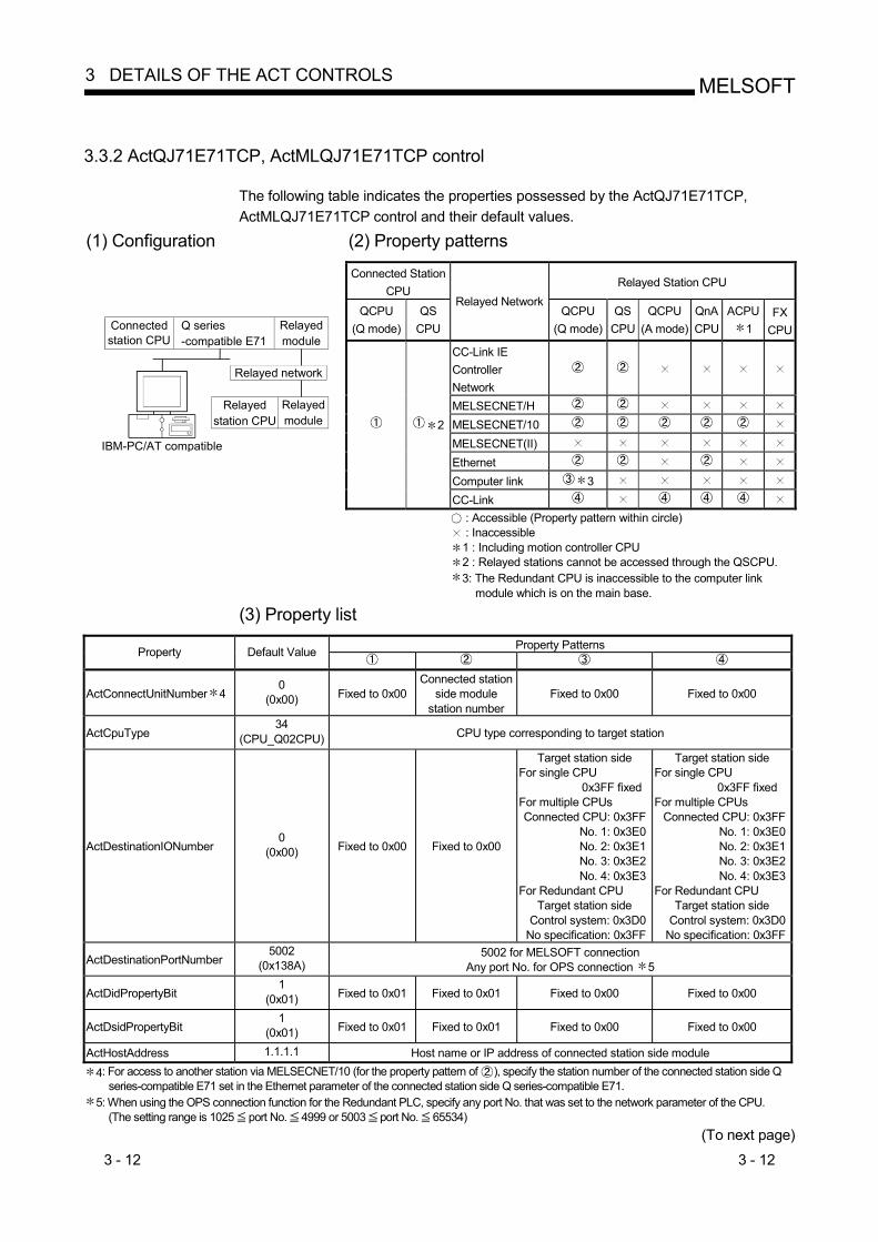
3 - 12 3 - 12
MELSOFT3 DETAILS OF THE ACT CONTROLS
3.3.2 ActQJ71E71TCP, ActMLQJ71E71TCP control
The following table indicates the properties possessed by the ActQJ71E71TCP, ActMLQJ71E71TCP control and their default values.
(1) Configuration (2) Property patterns Connected Station
CPU Relayed Station CPU
QCPU (Q mode)
QS CPU
Relayed NetworkQCPU
(Q mode)QS
CPU QCPU
(A mode) QnA CPU
ACPU1
FX CPU
CC-Link IE Controller Network
MELSECNET/H MELSECNET/10 MELSECNET(II) Ethernet Computer link 3
IBM-PC/AT compatible
Connected station CPU
Q series-compatible E71
Relayedmodule
Relayed network
Relayed station CPU
Relayedmodule
2
CC-Link : Accessible (Property pattern within circle) : Inaccessible 1 : Including motion controller CPU 2 : Relayed stations cannot be accessed through the QSCPU. 3: The Redundant CPU is inaccessible to the computer link
module which is on the main base. (3) Property list
Property Patterns Property Default Value
ActConnectUnitNumber 4 0
(0x00) Fixed to 0x00 Connected station
side module station number
Fixed to 0x00 Fixed to 0x00
ActCpuType 34
(CPU_Q02CPU) CPU type corresponding to target station
ActDestinationIONumber 0
(0x00) Fixed to 0x00 Fixed to 0x00
Target station side For single CPU
0x3FF fixed For multiple CPUs Connected CPU: 0x3FF
No. 1: 0x3E0 No. 2: 0x3E1 No. 3: 0x3E2 No. 4: 0x3E3
For Redundant CPU Target station side
Control system: 0x3D0 No specification: 0x3FF
Target station side For single CPU
0x3FF fixed For multiple CPUs
Connected CPU: 0x3FFNo. 1: 0x3E0No. 2: 0x3E1No. 3: 0x3E2No. 4: 0x3E3
For Redundant CPU Target station side
Control system: 0x3D0No specification: 0x3FF
ActDestinationPortNumber 5002
(0x138A) 5002 for MELSOFT connection
Any port No. for OPS connection 5
ActDidPropertyBit 1
(0x01) Fixed to 0x01 Fixed to 0x01 Fixed to 0x00 Fixed to 0x00
ActDsidPropertyBit 1
(0x01) Fixed to 0x01 Fixed to 0x01 Fixed to 0x00 Fixed to 0x00
ActHostAddress 1.1.1.1 Host name or IP address of connected station side module
4: For access to another station via MELSECNET/10 (for the property pattern of ), specify the station number of the connected station side Q series-compatible E71 set in the Ethernet parameter of the connected station side Q series-compatible E71.
5: When using the OPS connection function for the Redundant PLC, specify any port No. that was set to the network parameter of the CPU. (The setting range is 1025 port No. 4999 or 5003 port No. 65534)
(To next page)

3 - 13 3 - 13
MELSOFT3 DETAILS OF THE ACT CONTROLS
Property Patterns
Property Default Value
ActIONumber 6 1023
(0x3FF)
For single CPU 0x3FF fixed
For multiple CPUs Connected CPU: 0x3FF
No. 1: 0x3E0No. 2: 0x3E1No. 3: 0x3E2No. 4: 0x3E3
For Redundant CPU Control system: 0x3D0
No specification: 0x3FF
Target station side For single CPU
0x3FF fixed For multiple CPUs
Connected CPU: 0x3FFNo. 1: 0x3E0No. 2: 0x3E1No. 3: 0x3E2No. 4: 0x3E3
For Redundant CPU Target station side Control system: 0x3D0
No specification: 0x3FF
Connected station side relayed module I/O address
Connected station side relayed module I/O address
ActMultiDropChannelNumber7
0 (0x00) Fixed to 0x00 Fixed to 0x00
Multidrop channel number
Fixed to 0x00
ActNetworkNumber 8 1
(0x01) Network number of target
station side module Network number of target
station side module
Connected station side Q series-
compatible E71 network number
Connected station side Q series-
compatible E71 network number
ActPassword Empty Password set to the Q series-compatible E71 on the connected station side
ActSourceNetworkNumber 9 1
(0x01) IBM-PC/AT compatible side network number
ActSourceStationNumber 10 2
(0x02) IBM-PC/AT compatible side station number
ActStationNumber 6 1
(0x01) Connected station side module station number
Connected station side module station number
Connected station side Q series-
compatible E71 station number
Connected station side Q series-
compatible E71 station number
ActThroughNetworkType 0
(0x00) Refer to the property [ActThroughNetworkType] in Section 3.2.
ActTimeOut 10000 Any value specified by user in ms units.
ActUnitNumber 0
(0x00) Fixed to 0x00 Fixed to 0x00 Target station side
module station number
Target station side module station number (valid)
6 : As the I/O address, specify the value found by dividing the actual first I/O number by 16. 7 : Specify the following as the channel No. to be multidrop-linked.
0: Use default channel of module. 1: Channel 1 2: Channel 2
8 : For the property pattern of or , specify the value set in the target station side parameter for ActNetworkNumber and ActStationNumber. 9 : Specify the same network number as the MELSECNET/10 network number set to the Q series-compatible E71 in the Ethernet parameter
setting of the target station side Q series-compatible E71. 10: Specify the station number on the IBM-PC/AT compatible side to avoid setting the same station number as set to the Q series-compatible E71
within the same Ethernet loop.

3 - 14 3 - 14
MELSOFT3 DETAILS OF THE ACT CONTROLS
3.3.3 ActQJ71E71UDP, ActMLQJ71E71UDP control
The following table indicates the properties possessed by the ActQJ71E71UDP, ActMLQJ71E71UDP control and their default values.
(1) Configuration (2) Property patterns
Connected Station CPU
Relayed Station CPU
QCPU (Q mode)
QS CPU
Relayed Network QCPU
(Q mode)QS
CPU QCPU
(A mode) QnA CPU
ACPU1
FX CPU
CC-Link IE Controller Network
MELSECNET/H MELSECNET/10 MELSECNET(II) Ethernet Computer link 3
IBM-PC/AT compatible
Connected station CPU
Q series-compatible E71
Relayedmodule
Relayed network
Relayed station CPU
Relayedmodule
2
CC-Link
: Accessible (Property pattern within circle) : Inaccessible 1 : Including motion controller CPU 2 : Relayed stations cannot be accessed through the QSCPU. 3: The Redundant CPU is inaccessible to the computer link
module which is on the main base.
(3) Property list
Property Patterns Property Default Value
ActConnectUnitNumber 4 0
(0x00) Fixed to 0x00 Connected station
side module station number
Fixed to 0x00 Fixed to 0x00
ActCpuType 34
(CPU_Q02CPU) CPU type corresponding to target station
ActDestinationIONumber 0
(0x00) Fixed to 0x00 Fixed to 0x00
Target station side For single CPU
0x3FF fixed For multiple CPUs Connected CPU: 0x3FF
No. 1: 0x3E0 No. 2: 0x3E1 No. 3: 0x3E2 No. 4: 0x3E3
For Redundant CPU Target station side
Control system: 0x3D0 No specification: 0x3FF
Target station side For single CPU
0x3FF fixed For multiple CPUs
Connected CPU: 0x3FFNo. 1: 0x3E0No. 2: 0x3E1No. 3: 0x3E2No. 4: 0x3E3
For Redundant CPU Target station side
Control system: 0x3D0No specification: 0x3FF
ActDidPropertyBit 1
(0x01) Fixed to 0x01 Fixed to 0x01 Fixed to 0x00 Fixed to 0x00
ActDsidPropertyBit 1
(0x01) Fixed to 0x01 Fixed to 0x01 Fixed to 0x00 Fixed to 0x00
ActHostAddress 1.1.1.1 Host name or IP address of connected station side module
4: For access to another station via MELSECNET/10 (for the property pattern of ), specify the station number of the connected station side Q series-compatible E71 set in the Ethernet parameter of the connected station side Q series-compatible E71.
(To next page)
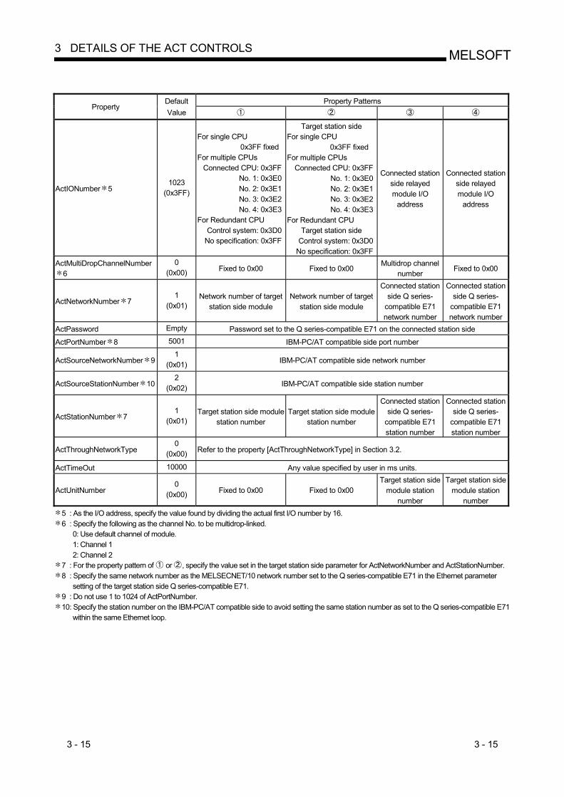
3 - 15 3 - 15
MELSOFT3 DETAILS OF THE ACT CONTROLS
Property Patterns
Property Default Value
ActIONumber 5 1023
(0x3FF)
For single CPU 0x3FF fixed
For multiple CPUs Connected CPU: 0x3FF
No. 1: 0x3E0No. 2: 0x3E1No. 3: 0x3E2No. 4: 0x3E3
For Redundant CPU Control system: 0x3D0
No specification: 0x3FF
Target station side For single CPU
0x3FF fixed For multiple CPUs
Connected CPU: 0x3FFNo. 1: 0x3E0No. 2: 0x3E1No. 3: 0x3E2No. 4: 0x3E3
For Redundant CPU Target station side
Control system: 0x3D0No specification: 0x3FF
Connected station side relayed module I/O
address
Connected station side relayed module I/O
address
ActMultiDropChannelNumber6
0 (0x00) Fixed to 0x00 Fixed to 0x00
Multidrop channel number
Fixed to 0x00
ActNetworkNumber 7 1
(0x01) Network number of target
station side module Network number of target
station side module
Connected station side Q series-
compatible E71 network number
Connected station side Q series-
compatible E71 network number
ActPassword Empty Password set to the Q series-compatible E71 on the connected station side
ActPortNumber 8 5001 IBM-PC/AT compatible side port number
ActSourceNetworkNumber 9 1
(0x01) IBM-PC/AT compatible side network number
ActSourceStationNumber 10 2
(0x02) IBM-PC/AT compatible side station number
ActStationNumber 7 1
(0x01) Target station side module
station number Target station side module
station number
Connected station side Q series-
compatible E71 station number
Connected station side Q series-
compatible E71 station number
ActThroughNetworkType 0
(0x00) Refer to the property [ActThroughNetworkType] in Section 3.2.
ActTimeOut 10000 Any value specified by user in ms units.
ActUnitNumber 0
(0x00) Fixed to 0x00 Fixed to 0x00 Target station side
module station number
Target station side module station
number 5 : As the I/O address, specify the value found by dividing the actual first I/O number by 16. 6 : Specify the following as the channel No. to be multidrop-linked.
0: Use default channel of module. 1: Channel 1 2: Channel 2
7 : For the property pattern of or , specify the value set in the target station side parameter for ActNetworkNumber and ActStationNumber. 8 : Specify the same network number as the MELSECNET/10 network number set to the Q series-compatible E71 in the Ethernet parameter
setting of the target station side Q series-compatible E71. 9 : Do not use 1 to 1024 of ActPortNumber. 10: Specify the station number on the IBM-PC/AT compatible side to avoid setting the same station number as set to the Q series-compatible E71
within the same Ethernet loop.

3 - 16 3 - 16
MELSOFT3 DETAILS OF THE ACT CONTROLS
3.3.4 ActAJ71QE71TCP, ActMLAJ71QE71TCP control
The following table indicates the properties possessed by the ActAJ71QE71TCP, ActMLAJ71QE71TCP control and their default values.
(1) Configuration (2) Property patterns Connected
Station CPURelayed Station CPU
QnACPU
Relayed NetworkQCPU
(Q mode)QS
CPU QCPU
(A mode) QnA CPU
ACPU1
FX CPU
CC-Link IE Controller Network
MELSECNET/H MELSECNET/10 MELSECNET(II) Ethernet Computer link
IBM-PC/AT compatible
Connected station CPU QE71
Relayedmodule
Relayed network
Relayed station CPU
Relayedmodule
CC-Link
: Accessible (Property pattern within circle) : Inaccessible 1 : Including motion controller CPU
(3) Property list
Property Patterns
Property Default Value
ActCpuTimeOut 40 Any value specified by user in 250ms units
ActCpuType 17
(CPU_Q2ACPU) CPU type corresponding to target station
ActDestinationPortNumber 1280
(0x500) Port number of connected station side module
ActHostAddress 1.1.1.1 Host name or IP address of connected station side module
ActNetworkNumber 0
(0x00) 0x00 Target station side module
network number
ActPacketType 2
(PACKET_ASCII) PACKET_BINARY or PACKET_ASCII
ActStationNumber 255
(0xFF) 0xFF Target station side module
station number
ActTimeOut 10000 Any value specified by user in ms units

3 - 17 3 - 17
MELSOFT3 DETAILS OF THE ACT CONTROLS
3.3.5 ActAJ71QE71UDP, ActMLAJ71QE71UDP control
The following table indicates the properties possessed by the ActAJ71QE71UDP, ActMLAJ71QE71UDP control and their default values.
(1) Configuration (2) Property patterns Connected
Station CPURelayed Station CPU
QnACPU Relayed Network
QCPU (Q mode)
QS CPU
QCPU (A mode)
QnA CPU
ACPU1
FX CPU
CC-Link IE Controller Network
MELSECNET/H MELSECNET/10 MELSECNET(II) Ethernet Computer link
IBM-PC/AT compatible
Connected station CPU QE71
Relayedmodule
Relayed network
Relayed station CPU
Relayedmodule
CC-Link
: Accessible (Property pattern within circle) : Inaccessible 1 : Including motion controller CPU
(3) Property list
Property Patterns Property Default Value
ActConnectUnitNumber 1 0
(0x00) Fixed to 0x00 Connected station side module station number Fixed to 0x00
ActCpuType 17
(CPU_Q2ACPU) CPU type corresponding to target station
ActHostAddress 1.1.1.1 Host name or IP address of connected station side module
ActIONumber 7 1023
(0x3FF) Fixed to 0x3FF Fixed to 0x3FF Connected station side relayed module I/O address
ActNetworkNumber 2 1
(0x01) Target station side module
network number Target station side module
network number Connected station side QE71
network number ActPortNumber 3 6 5001 IBM-PC/AT compatible side port number
ActSourceNetworkNumber 4 1
(0x01) IBM-PC/AT compatible side network number
ActSourceStationNumber 5 2
(0x02) IBM-PC/AT compatible side station number
ActStationNumber 2 1
(0x01) Target station side module
station number Target station side module
station number Connected station side QE71
station number ActHostAddress 1.1.1.1 Host name or IP address of connected station side module ActTimeOut 10000 Any value specified by user in ms units
ActUnitNumber 0
(0x00) Fixed to 0x00 Fixed to 0x00 Target station side module station number
1: For access to another station via MELSECNET/10 (for the property pattern of ), specify the station number of the connected station side QE71 set in the Ethernet parameter of the connected station side QE71.
2: For the property pattern of or , specify the value set in the target station side parameter for ActNetworkNumber and ActStationNumber. 3: Specify fixed "5001" when the Ethernet parameter setting of the connected station side QE71 is other than the "automatic response system".
Specify fixed "0" when the Ethernet parameter setting of the connected station side QE71 is the "automatic response system". 4: Specify the same network number as the MELSECNET/10 network number set to the QE71 in the Ethernet parameter setting of the target
station side QE71. 5: Specify the station number on the IBM-PC/AT compatible side to avoid setting the same station number as set to the QE71 within the same
Ethernet loop. 6: Do not use 1 to 1024 of ActPortNumber. 7: As the I/O address, specify the value found by dividing the actual first I/O number by 16.
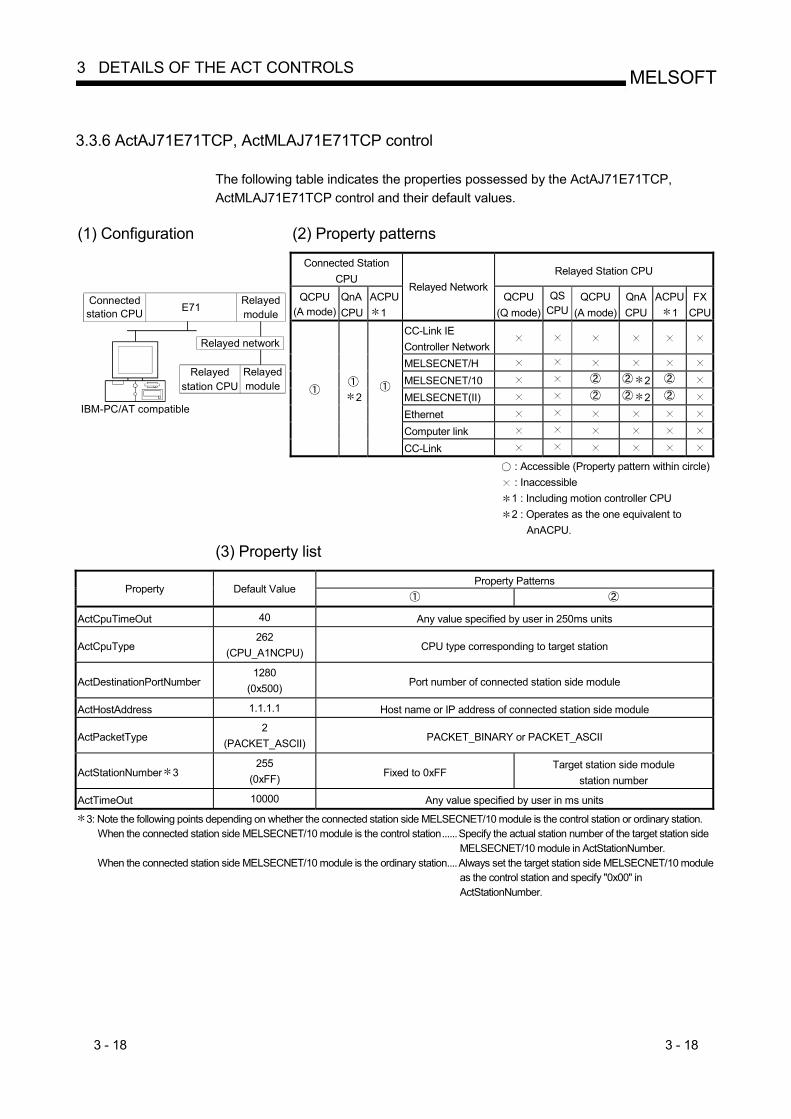
3 - 18 3 - 18
MELSOFT3 DETAILS OF THE ACT CONTROLS
3.3.6 ActAJ71E71TCP, ActMLAJ71E71TCP control
The following table indicates the properties possessed by the ActAJ71E71TCP, ActMLAJ71E71TCP control and their default values.
(1) Configuration (2) Property patterns
Connected Station CPU
Relayed Station CPU
QCPU(A mode)
QnACPU
ACPU1
Relayed Network QCPU
(Q mode)QS
CPU QCPU
(A mode) QnA CPU
ACPU1
FX CPU
CC-Link IE Controller Network
MELSECNET/H MELSECNET/10 2 MELSECNET(II) 2 Ethernet Computer link
IBM-PC/AT compatible
Connected station CPU E71
Relayedmodule
Relayed network
Relayed station CPU
Relayedmodule
2
CC-Link
: Accessible (Property pattern within circle) : Inaccessible 1 : Including motion controller CPU 2 : Operates as the one equivalent to
AnACPU. (3) Property list
Property Patterns
Property Default Value
ActCpuTimeOut 40 Any value specified by user in 250ms units
ActCpuType 262
(CPU_A1NCPU) CPU type corresponding to target station
ActDestinationPortNumber 1280
(0x500) Port number of connected station side module
ActHostAddress 1.1.1.1 Host name or IP address of connected station side module
ActPacketType 2
(PACKET_ASCII) PACKET_BINARY or PACKET_ASCII
ActStationNumber 3 255
(0xFF) Fixed to 0xFF Target station side module
station number
ActTimeOut 10000 Any value specified by user in ms units
3: Note the following points depending on whether the connected station side MELSECNET/10 module is the control station or ordinary station. When the connected station side MELSECNET/10 module is the control station......Specify the actual station number of the target station side
MELSECNET/10 module in ActStationNumber. When the connected station side MELSECNET/10 module is the ordinary station....Always set the target station side MELSECNET/10 module
as the control station and specify "0x00" in ActStationNumber.
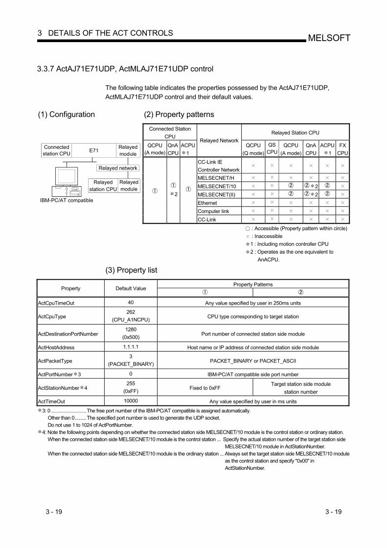
3 - 19 3 - 19
MELSOFT3 DETAILS OF THE ACT CONTROLS
3.3.7 ActAJ71E71UDP, ActMLAJ71E71UDP control
The following table indicates the properties possessed by the ActAJ71E71UDP, ActMLAJ71E71UDP control and their default values.
(1) Configuration (2) Property patterns
Connected Station CPU
Relayed Station CPU
QCPU(A mode)
QnACPU
ACPU1
Relayed Network QCPU
(Q mode)QS
CPU QCPU
(A mode) QnA CPU
ACPU1
FX CPU
CC-Link IE Controller Network
MELSECNET/H MELSECNET/10 2 MELSECNET(II) 2 Ethernet Computer link
IBM-PC/AT compatible
Connected station CPU E71
Relayedmodule
Relayed network
Relayed station CPU
Relayedmodule
2
CC-Link
: Accessible (Property pattern within circle) : Inaccessible 1 : Including motion controller CPU 2 : Operates as the one equivalent to
AnACPU. (3) Property list
Property Patterns
Property Default Value
ActCpuTimeOut 40 Any value specified by user in 250ms units
ActCpuType 262
(CPU_A1NCPU) CPU type corresponding to target station
ActDestinationPortNumber 1280
(0x500) Port number of connected station side module
ActHostAddress 1.1.1.1 Host name or IP address of connected station side module
ActPacketType 3
(PACKET_BINARY) PACKET_BINARY or PACKET_ASCII
ActPortNumber 3 0 IBM-PC/AT compatible side port number
ActStationNumber 4 255
(0xFF) Fixed to 0xFF Target station side module
station number
ActTimeOut 10000 Any value specified by user in ms units
3: 0 ............................The free port number of the IBM-PC/AT compatible is assigned automatically. Other than 0.........The specified port number is used to generate the UDP socket. Do not use 1 to 1024 of ActPortNumber.
4: Note the following points depending on whether the connected station side MELSECNET/10 module is the control station or ordinary station. When the connected station side MELSECNET/10 module is the control station ... Specify the actual station number of the target station side
MELSECNET/10 module in ActStationNumber. When the connected station side MELSECNET/10 module is the ordinary station ... Always set the target station side MELSECNET/10 module
as the control station and specify "0x00" in ActStationNumber.

3 - 20 3 - 20
MELSOFT3 DETAILS OF THE ACT CONTROLS
3.3.8 ActQNUDECPUTCP, ActMLQNUDECPUTCP control
The following table indicates the properties possessed by the ActQNUDECPUTCP, ActMLQNUDECPUTCP control and their default values.
(1) Configuration (2) Property patterns
Connected Station CPU
Relayed Station CPU
QnUDE(H)
Relayed Network QCPU
(Q mode)QS
CPU QCPU
(A mode) QnA CPU
ACPU1
FX CPU
CC-Link IE Controller Network
MELSECNET/H MELSECNET/10 MELSECNET(II) Ethernet Computer link 2
IBM-PC/AT compatible
Connectedstation CPU
Relayedmodule
Relayed network
Relayedstation CPU
Relayedmodule
CC-Link
: Accessible (Property pattern within circle) : Inaccessible 1 : Including motion controller CPU 2: The Redundant CPU is inaccessible to
the computer link module which is on the main base.
(3) Property list
Property Patterns Property Default Value
ActCpuType 144
(CPU_Q03UDECPU) CPU type corresponding to target station
ActDestinationIONumber 0
(0x00) Fixed to
0x00 Fixed to 0x00
Target station side For single CPU
0x3FF fixed For multiple CPUs Connected CPU: 0x3FF
No. 1: 0x3E0 No. 2: 0x3E1 No. 3: 0x3E2 No. 4: 0x3E3
For Redundant CPU Target station side
Control system: 0x3D0 No specification: 0x3FF
Target station side For single CPU
0x3FF fixed For multiple CPUs
Connected CPU: 0x3FFNo. 1: 0x3E0No. 2: 0x3E1No. 3: 0x3E2No. 4: 0x3E3
For Redundant CPU Target station side
Control system: 0x3D0No specification: 0x3FF
ActDidPropertyBit 1
(0x01) Fixed to
0x01 Fixed to 0x01 Fixed to 0x00 Fixed to 0x00
ActDsidPropertyBit 1
(0x01) Fixed to
0x01 Fixed to 0x01 Fixed to 0x00 Fixed to 0x00
ActHostAddress 1.1.1.1 Host name or IP address of connected station side module
ActIntelligentPreferenceBit 0
(0x00) Fixed to
0x00 Fixed to 0x00 Target station
Q mode : 0x01 Not Q mode : 0x00
Target station Q mode : 0x01
Not Q mode : 0x00
(To next page)

3 - 21 3 - 21
MELSOFT3 DETAILS OF THE ACT CONTROLS
Property Patterns Property
Default Value
ActIONumber 3 1023
(0x3FF)
For single CPU 0x3FF fixed
For multiple CPUs Connected CPU: 0x3FF
No. 1: 0x3E0No. 2: 0x3E1No. 3: 0x3E2No. 4: 0x3E3
Target station side For single CPU
0x3FF fixed For multiple CPUs
Connected CPU: 0x3FFNo. 1: 0x3E0No. 2: 0x3E1No. 3: 0x3E2No. 4: 0x3E3
For Redundant CPU Target station side Control system: 0x3D0
No specification: 0x3FF
Connected station side relayed module I/O address
Connected station side relayed module I/O address
ActMultiDropChannelNumber4
0 (0x00) Fixed to 0x00 Fixed to 0x00
Multidrop channel number
Fixed to 0x00
ActNetworkNumber 5 0
(0x00) Fixed to 0x00 Network number of target
station side module Fixed to 0x00 Fixed to 0x00
ActPassword Empty Password set to the connected station side
ActStationNumber 5 0
(0x00) Fixed to 0xFF Target station side module
station number Fixed to 0xFF Fixed to 0xFF
ActThroughNetworkType 0
(0x00) Refer to the property [ActThroughNetworkType] in Section 3.2.
ActTimeOut 10000 Any value specified by user in ms units.
ActUnitNumber 0
(0x00) Fixed to 0x00 Fixed to 0x00 Target station side
module station number
Target station side module station
number 3: As the I/O address, specify the value found by dividing the actual first I/O number by 16. 4: Specify the following as the channel No. to be multidrop-linked.
0: Use default channel of module. 1: Channel 1 2: Channel 2
5: For the property pattern of or , specify the value set in the target station side parameter for ActNetworkNumber and ActStationNumber.

3 - 22 3 - 22
MELSOFT3 DETAILS OF THE ACT CONTROLS
3.3.9 ActQNUDECPUUDP, ActMLQNUDECPUUDP control
The following table indicates the properties possessed by the ActQNUDECPUUDP, ActMLQNUDECPUUDP control and their default values.
POINT
This control can also make direct communication without specifying the IP address of the connected station (Built-in Ethernet port QCPU).
(1) Configuration (2) Property patterns
Connected
Station CPU Relayed Station CPU
QnUDE(H)
Relayed Network QCPU
(Q mode)QS
CPU QCPU
(A mode) QnA CPU
ACPU1
FX CPU
CC-Link IE Controller Network
MELSECNET/H MELSECNET/10 MELSECNET(II) Ethernet Computer link 2
IBM-PC/AT compatible
Connectedstation CPU
Relayedmodule
Relayed network
Relayedstation CPU
Relayedmodule
CC-Link : Accessible (Property pattern within circle) : Inaccessible 1 :Including motion controller CPU 2: The Redundant CPU is inaccessible to
the computer link module which is on the main base.
(3) Property list
Property Patterns Property Default Value
ActCpuType 144
(CPU_Q03UDECPU) CPU type corresponding to target station
ActDestinationIONumber 0
(0x00) Fixed to
0x00 Fixed to 0x00
Target station side For single CPU
0x3FF fixed For multiple CPUs Connected CPU: 0x3FF
No. 1: 0x3E0 No. 2: 0x3E1 No. 3: 0x3E2 No. 4: 0x3E3
For Redundant CPU Target station side
Control system: 0x3D0 No specification: 0x3FF
Target station side For single CPU
0x3FF fixed For multiple CPUs
Connected CPU: 0x3FFNo. 1: 0x3E0No. 2: 0x3E1No. 3: 0x3E2No. 4: 0x3E3
For Redundant CPU Target station side
Control system: 0x3D0No specification: 0x3FF
ActDidPropertyBit 1
(0x01) Fixed to
0x01 Fixed to 0x01 Fixed to 0x00 Fixed to 0x00
ActDsidPropertyBit 1
(0x01) Fixed to
0x01 Fixed to 0x01 Fixed to 0x00 Fixed to 0x00
ActHostAddress 1.1.1.1 Host name or IP address of connected station side CPU 3
ActIntelligentPreferenceBit 0
(0x00) Fixed to
0x00 Fixed to 0x00 Target station
Q mode : 0x01 Not Q mode : 0x00
Target station Q mode : 0x01
Not Q mode : 0x003: Invalid with direct communication without specifying the IP address.
(To next page)
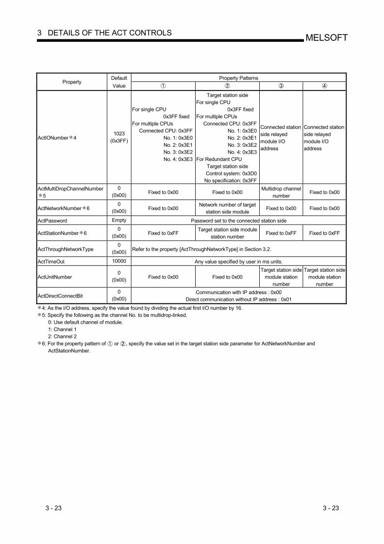
3 - 23 3 - 23
MELSOFT3 DETAILS OF THE ACT CONTROLS
Property Patterns Property
Default Value
ActIONumber 4 1023
(0x3FF)
For single CPU 0x3FF fixed
For multiple CPUs Connected CPU: 0x3FF
No. 1: 0x3E0No. 2: 0x3E1No. 3: 0x3E2No. 4: 0x3E3
Target station side For single CPU
0x3FF fixed For multiple CPUs
Connected CPU: 0x3FFNo. 1: 0x3E0No. 2: 0x3E1No. 3: 0x3E2No. 4: 0x3E3
For Redundant CPU Target station side Control system: 0x3D0
No specification: 0x3FF
Connected station side relayed module I/O address
Connected station side relayed module I/O address
ActMultiDropChannelNumber5
0 (0x00) Fixed to 0x00 Fixed to 0x00
Multidrop channel number
Fixed to 0x00
ActNetworkNumber 6 0
(0x00) Fixed to 0x00 Network number of target
station side module Fixed to 0x00 Fixed to 0x00
ActPassword Empty Password set to the connected station side
ActStationNumber 6 0
(0x00) Fixed to 0xFF Target station side module
station number Fixed to 0xFF Fixed to 0xFF
ActThroughNetworkType 0
(0x00) Refer to the property [ActThroughNetworkType] in Section 3.2.
ActTimeOut 10000 Any value specified by user in ms units.
ActUnitNumber 0
(0x00) Fixed to 0x00 Fixed to 0x00 Target station side
module station number
Target station side module station
number
ActDirectConnectBit 0
(0x00) Communication with IP address : 0x00
Direct communication without IP address : 0x01 4: As the I/O address, specify the value found by dividing the actual first I/O number by 16. 5: Specify the following as the channel No. to be multidrop-linked.
0: Use default channel of module. 1: Channel 1 2: Channel 2
6: For the property pattern of or , specify the value set in the target station side parameter for ActNetworkNumber and ActStationNumber.
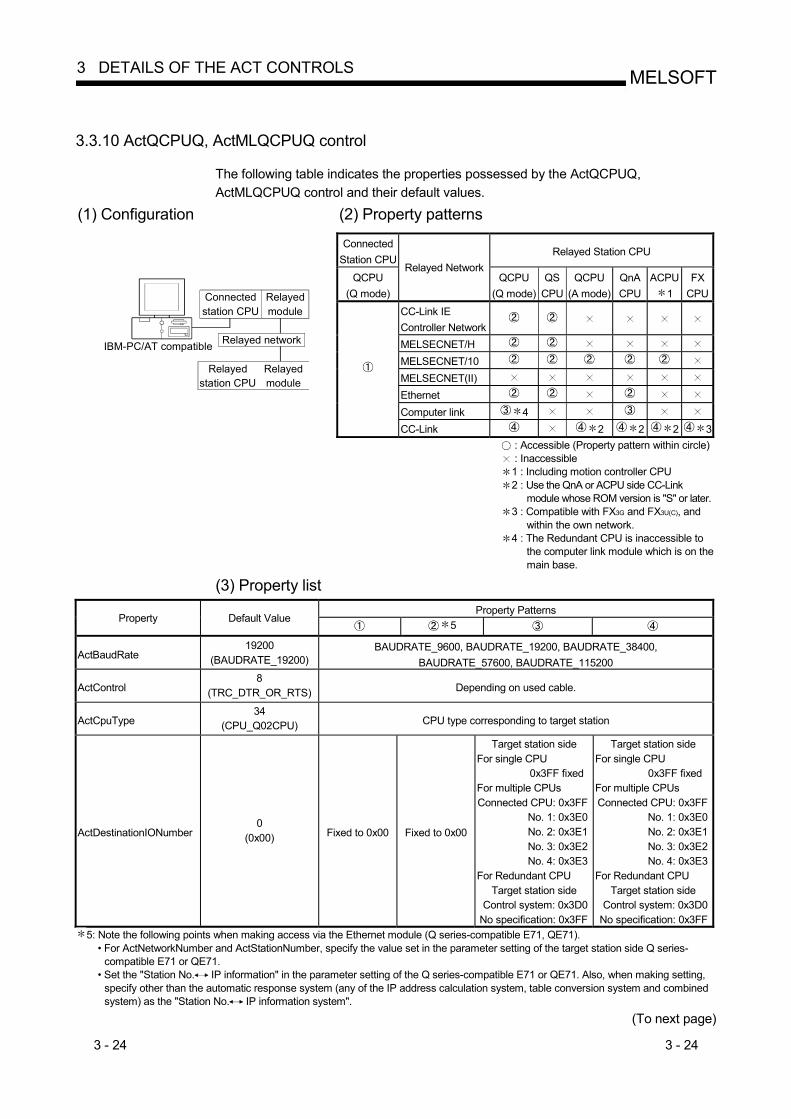
3 - 24 3 - 24
MELSOFT3 DETAILS OF THE ACT CONTROLS
3.3.10 ActQCPUQ, ActMLQCPUQ control
The following table indicates the properties possessed by the ActQCPUQ, ActMLQCPUQ control and their default values.
(1) Configuration (2) Property patterns Connected
Station CPURelayed Station CPU
QCPU (Q mode)
Relayed NetworkQCPU
(Q mode)QS
CPU QCPU
(A mode) QnA CPU
ACPU1
FX CPU
CC-Link IE Controller Network
MELSECNET/H MELSECNET/10 MELSECNET(II) Ethernet Computer link 4
IBM-PC/AT compatible
Connectedstation CPU
Relayedmodule
Relayed network
Relayedstation CPU
Relayedmodule
CC-Link 2 2 2 3 : Accessible (Property pattern within circle) : Inaccessible 1 : Including motion controller CPU 2 : Use the QnA or ACPU side CC-Link
module whose ROM version is "S" or later. 3 : Compatible with FX3G and FX3U(C), and
within the own network. 4 : The Redundant CPU is inaccessible to
the computer link module which is on the main base.
(3) Property list Property Patterns
Property Default Value 5
ActBaudRate 19200
(BAUDRATE_19200) BAUDRATE_9600, BAUDRATE_19200, BAUDRATE_38400,
BAUDRATE_57600, BAUDRATE_115200
ActControl 8
(TRC_DTR_OR_RTS) Depending on used cable.
ActCpuType 34
(CPU_Q02CPU) CPU type corresponding to target station
ActDestinationIONumber 0
(0x00) Fixed to 0x00 Fixed to 0x00
Target station side For single CPU
0x3FF fixed For multiple CPUs Connected CPU: 0x3FF
No. 1: 0x3E0 No. 2: 0x3E1 No. 3: 0x3E2 No. 4: 0x3E3
For Redundant CPU Target station side
Control system: 0x3D0 No specification: 0x3FF
Target station side For single CPU
0x3FF fixed For multiple CPUs Connected CPU: 0x3FF
No. 1: 0x3E0No. 2: 0x3E1No. 3: 0x3E2No. 4: 0x3E3
For Redundant CPU Target station side
Control system: 0x3D0No specification: 0x3FF
5: Note the following points when making access via the Ethernet module (Q series-compatible E71, QE71). • For ActNetworkNumber and ActStationNumber, specify the value set in the parameter setting of the target station side Q series-
compatible E71 or QE71. • Set the "Station No. IP information" in the parameter setting of the Q series-compatible E71 or QE71. Also, when making setting,
specify other than the automatic response system (any of the IP address calculation system, table conversion system and combined system) as the "Station No. IP information system".
(To next page)

3 - 25 3 - 25
MELSOFT3 DETAILS OF THE ACT CONTROLS
Property Patterns
Property Default Value 7
ActDidPropertyBit 1
(0x01) Fixed to 0x01 Fixed to 0x01 Fixed to 0x00 Fixed to 0x00
ActDisdPropertyBit 1
(0x01) Fixed to 0x01 Fixed to 0x01 Fixed to 0x00 Fixed to 0x00
ActIntelligentPreferenceBit 0
(0x00) Fixed to 0x00 Fixed to 0x00
0x01 (target station is QCPU (Q mode), 0x00 (target station is other than QCPU
(Q mode))
0x01 (target station is QCPU (Q mode), 0x00 (target station is other than QCPU
(Q mode))
ActIONumber 6 1023
(0x3FF)
For single CPU 0x3FF fixed
For multiple CPUs Connected CPU: 0x3FF
No. 1: 0x3E0No. 2: 0x3E1No. 3: 0x3E2No. 4: 0x3E3
For Redundant CPU Control system: 0x3D0
No specification: 0x3FF
Target station side For single CPU
0x3FF fixed For multiple CPUs Connected CPU: 0x3FF
No. 1: 0x3E0No. 2: 0x3E1No. 3: 0x3E2No. 4: 0x3E3
For Redundant CPU Target station side
Control system: 0x3D0No specification: 0x3FF
Connected station side module I/O
address
Connected station side module I/O
address
ActMultiDropChannelNumber8
0 (0x00) Fixed to 0x00 Fixed to 0x00
Multidrop channel number
Fixed to 0x02
ActNetworkNumber 0
(0x00) Fixed to 0x00 Target station side
module network number Fixed to 0x00 Fixed to 0x00
ActPortNumber 1
(PORT_1) IBM-PC/AT compatible side COM port number
ActStationNumber 255
(0xFF) Fixed to 0xFF Target station side
module station number Fixed to 0xFF Fixed to 0xFF
ActThroughNetworkType 0
(0x00) Refer to the property [ActThroughNetworkType] in Section 3.2.
ActTimeOut 10000 Any value specified by user in ms units
ActUnitNumber 0
(0x00) Fixed to 0x00 Fixed to 0x00 Target station side
module station number
Target station side module station
number 6: As the I/O address, specify the value found by dividing the actual first I/O number by 16. 7: Note the following points when making access via the Ethernet module (Q series-compatible E71, QE71).
• For ActNetworkNumber and ActStationNumber, specify the value set in the parameter setting of the target station side Q series-compatible E71 or QE71.
• Set the "Station No. IP information" in the parameter setting of the Q series-compatible E71 or QE71. Also, when making setting, specify other than the automatic response system (any of the IP address calculation system, table conversion system and combined system) as the "Station No. IP information system".
8: Specify the following as the channel No. to be multidrop-linked. 0: Use default channel of module. 1: Channel 1 2: Channel 2

3 - 26 3 - 26
MELSOFT3 DETAILS OF THE ACT CONTROLS
3.3.11 ActQCPUA, ActMLQCPUA control
The following table indicates the properties possessed by the ActQCPUA, ActMLQCPUA control and their default values.
(1) Configuration (2) Property patterns Connected
Station CPURelayed Station CPU
QCPU (A mode)
Relayed Network QCPU
(Q mode)QS
CPU QCPU
(A mode) QnA CPU
ACPU1
FX CPU
CC-Link IE Controller Network
MELSECNET/H MELSECNET/10 MELSECNET(II) Ethernet Computer link
IBM-PC/AT compatible
Connectedstation CPU
Relayedmodule
Relayed network
Relayedstation CPU
Relayedmodule
CC-Link
: Accessible (Property pattern within circle) : Inaccessible 1 : Including motion controller CPU
(3) Property list
Property Patterns Property Default Value
ActBaudRate 9600
(BAUDRATE_9600) BAUDRATE_9600, BAUDRATE_19200, BAUDRATE_38400,
BAUDRATE_57600, BAUDRATE_115200
ActControl 8
(TRC_DTR_OR_RTS) Depending on used cable.
ActCpuType 321
(CPU_Q02CPU_A) CPU type corresponding to target station
ActNetworkNumber 0
(0x00) Fixed to 0x00 Target station side module
network number Fixed to 0x00
ActPortNumber 1
(PORT_1) IBM-PC/AT compatible side COM port number
ActStationNumber 255
(0xFF) Fixed to 0xFF Target station side module
station number Target station side module
station number
ActTimeOut 10000 Any value specified by user in ms units.

3 - 27 3 - 27
MELSOFT3 DETAILS OF THE ACT CONTROLS
3.3.12 ActQnACPU, ActMLQnACPU control
The following table indicates the properties possessed by the ActQnACPU, ActMLQnACPU control and their default values.
(1) Configuration (2) Property patterns
Connected Station CPU
Relayed Station CPU
QnACPU
Relayed NetworkQCPU
(Q mode)QS
CPU QCPU
(A mode) QnA CPU
ACPU1
FX CPU
CC-Link IE Controller Network
MELSECNET/H MELSECNET/10 MELSECNET(II) Ethernet Computer link
IBM-PC/AT compatible
Connectedstation CPU
Relayedmodule
Relayed network
Relayedstation CPU
Relayedmodule
CC-Link
: Accessible (Property pattern within circle) : Inaccessible 1 : Including motion controller CPU
(3) Property list
Property Patterns Property Default Value
3
ActBaudRate 19200
(BAUDRATE_19200) BAUDRATE_9600, BAUDRATE_19200, BAUDRATE_38400 4
ActControl 8
(TRC_DTR_OR_RTS) Depending on used cable.
ActCpuType 17
(CPU_Q2ACPU) CPU type corresponding to target station
ActIONumber 2 1023
(0x3FF) Fixed to 0x3FF Fixed to 0x3FF Fixed to 0x3FF Connected station side
module I/O address
ActNetworkNumber 0
(0x00) Fixed to 0x00 Target station side
module network numberFixed to 0x00 Fixed to 0x00
ActPortNumber 1
(PORT_1) IBM-PC/AT compatible side COM port number
ActStationNumber 255
(0xFF) Fixed to 0xFF Target station side
module station numberTarget station side
module station number Fixed to 0xFF
ActTimeOut 10000 Any value specified by user in ms units.
ActUnitNumber 0
(0x00) Fixed to 0x00 Fixed to 0x00 Fixed to 0x00 Target station side
module station number2: As the I/O address, specify the value found by dividing the actual first I/O number by 16. 3: Note the following points when making access via the Ethernet module (QE71).
• For ActNetworkNumber and ActStationNumber, specify the value set in the parameter setting of the target station side QE71. • Set the "Station No. IP information" in the parameter setting of the QE71. Also, when making setting, specify other than the
automatic response system (any of the IP address calculation system, table conversion system and combined system) as the "Station No. IP information system".
4: Usable for only the QnACPU version 9707B or later.

3 - 28 3 - 28
MELSOFT3 DETAILS OF THE ACT CONTROLS
3.3.13 ActACPU, ActMLACPU control
The following table indicates the properties possessed by the ActACPU, ActMLACPU control and their default values.
(1) Configuration (2) Property patterns
Connected Station CPU Relayed Station CPU
ACPU 1 Relayed Network
QCPU (Q mode)
QS CPU
QCPU (A mode)
QnA CPU
ACPU1
FX CPU
CC-Link IE Controller Network
MELSECNET/H MELSECNET/10 MELSECNET(II) Ethernet Computer link
IBM-PC/AT compatible
Connectedstation CPU
Relayedmodule
Relayed network
Relayedstation CPU
Relayedmodule
CC-Link : Accessible (Property pattern within circle) : Inaccessible 1 : Including motion controller CPU
(3) Property list Property Patterns
Property Default Value
ActBaudRate 9600
(BAUDRATE_9600) Fixed to BAUDRATE_9600 2
ActControl 8
(TRC_DTR_OR_RTS) Depending on used cable.
ActCpuType 262
(CPU_A1NCPU) CPU type corresponding to target station
ActNetworkNumber 0
(0x00) Fixed to 0x00
Target station side module network number
Fixed to 0x00
ActPortNumber 1
(PORT_1) IBM-PC/AT compatible side COM port number
ActStationNumber 255
(0xFF) Fixed to 0xFF
Target station side module station number
Target station side module station number
ActTimeOut 10000 Any value specified by user in ms units. 2: BAUDRATE_9600 may be used only when the connected station CPU is the A2USHCPU-S1.

3 - 29 3 - 29
MELSOFT3 DETAILS OF THE ACT CONTROLS
3.3.14 ActFXCPU, ActMLFXCPU control
The following table indicates the properties possessed by the ActFXCPU, ActMLFXCPU control and their default values.
(1) Configuration (2) Property patterns Connected
Station CPURelayed Station CPU
FXCPU
Relayed NetworkQCPU
(Q mode)QS
CPU QCPU
(A mode) QnA CPU
ACPU1
FX CPU
CC-Link IE Controller Network
MELSECNET/H MELSECNET/10 MELSECNET(II) Ethernet Computer link
IBM-PC/AT compatible
Connectedstation CPU
Relayedmodule
Relayed network
Relayedstation CPU
Relayedmodule
CC-Link
: Accessible (Property pattern within circle) : Inaccessible 1 : Including motion controller CPU
(3) Property list
Property Patterns Property Default Value
FX0(S), FX0N, FX1, FX1S, FX2(C) Fixed to CBR_9600 FX1N(C), FX2N(C) CBR_9600, CBR_19200 ActBaudRate
9600 (CBR _9600)
FX3UC, FX3G CBR_9600, CBR_19200, CBR_38400, CBR_57600, CBR_115200
ActControl 8
(TRC_DTR_OR_RTS) Depending on used cable.
ActCpuType 513
(CPU_FX0CPU) CPU type corresponding to target station
ActPortNumber 1
(PORT_1) IBM-PC/AT compatible side COM port number
ActTimeOut 10000 Any value specified by user in ms units.
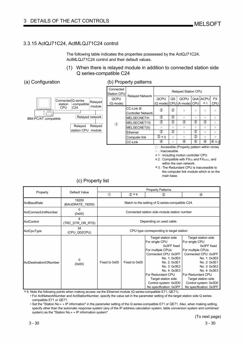
3 - 30 3 - 30
MELSOFT3 DETAILS OF THE ACT CONTROLS
3.3.15 ActQJ71C24, ActMLQJ71C24 control
The following table indicates the properties possessed by the ActQJ71C24, ActMLQJ71C24 control and their default values.
(1) When there is relayed module in addition to connected station side
Q series-compatible C24 (a) Configuration (b) Property patterns
Connected Station CPU
Relayed Station CPU
QCPU (Q mode)
Relayed NetworkQCPU
(Q mode)QS
CPU QCPU
(A mode) QnA CPU
ACPU1
FX CPU
CC-Link IE Controller Network
MELSECNET/H MELSECNET/10 MELSECNET(II) Ethernet Computer link 3
IBM-PC/AT compatible
Connected stationCPU
Q series-compatibleC24
Relayedmodule
Relayed network
Relayed station CPU
Relayedmodule
CC-Link 2 : Accessible (Property pattern within circle) : Inaccessible 1 : Including motion controller CPU 2 : Compatible with FX3G and FX3U(C), and
within the own network. 3 : The Redundant CPU is inaccessible to
the computer link module which is on the main base.
(c) Property list
Property Patterns Property Default Value
4
ActBaudRate 19200
(BAUDRATE_19200) Match to the setting of Q series-compatible C24.
ActConnectUnitNumber 0
(0x00) Connected station side module station number
ActControl 8
(TRC_DTR_OR_RTS) Depending on used cable.
ActCpuType 34
(CPU_Q02CPU) CPU type corresponding to target station
ActDestinationIONumber 0
(0x00) Fixed to 0x00 Fixed to 0x00
Target station side For single CPU
0x3FF fixed For multiple CPUs Connected CPU: 0x3FF
No. 1: 0x3E0 No. 2: 0x3E1 No. 3: 0x3E2 No. 4: 0x3E3
For Redundant CPU Target station side
Control system: 0x3D0 No specification: 0x3FF
Target station side For single CPU
0x3FF fixed For multiple CPUs Connected CPU: 0x3FF
No. 1: 0x3E0No. 2: 0x3E1No. 3: 0x3E2No. 4: 0x3E3
For Redundant CPU Target station side
Control system: 0x3D0No specification: 0x3FF
4: Note the following points when making access via the Ethernet module (Q series-compatible E71, QE71). • For ActNetworkNumber and ActStationNumber, specify the value set in the parameter setting of the target station side Q series-
compatible E71 or QE71. • Set the "Station No. IP information" in the parameter setting of the Q series-compatible E71 or QE71. Also, when making setting,
specify other than the automatic response system (any of the IP address calculation system, table conversion system and combined system) as the "Station No. IP information system".
(To next page)

3 - 31 3 - 31
MELSOFT3 DETAILS OF THE ACT CONTROLS
Property Patterns
Property Default Value 6
ActDidPropertyBit 1
(0x01) Fixed to 0x01 Fixed to 0x01 Fixed to 0x00 Fixed to 0x00
ActDisdPropertyBit 1
(0x01) Fixed to 0x01 Fixed to 0x01 Fixed to 0x00 Fixed to 0x00
ActIntelligentPreferenceBit 0
(0x00) Fixed to 0x00 Fixed to 0x00 Fixed to 0x00 Fixed to 0x00
ActIONumber 5 1023
(0x3FF)
For single CPU 0x3FF fixed
For multiple CPUs Connected CPU: 0x3FF
No. 1: 0x3E0No. 2: 0x3E1No. 3: 0x3E2No. 4: 0x3E3
For Redundant CPU Control system: 0x3D0No specification: 0x3FF
Target station side For single CPU
0x3FF fixed For multiple CPUs Connected CPU: 0x3FF
No. 1: 0x3E0No. 2: 0x3E1No. 3: 0x3E2No. 4: 0x3E3
For Redundant CPU Target station side
Control system: 0x3D0 No specification: 0x3FF
Connected station side module I/O
address
Connected station side module I/O
address
ActMultiDropChannelNumber7
0 (0x00) Fixed to 0x00 Fixed to 0x00
Multidrop channel number
Fixed to 0x00
ActNetworkNumber 0
(0x00) Fixed to 0x00 Target station side
module network numberFixed to 0x00 Fixed to 0x00
ActParity 1
(ODD_PARITY) Match to the setting of Q series-compatible C24.
ActPortNumber 1
(PORT_1) IBM-PC/AT compatible side COM port number
ActStationNumber 255
(0xFF) Fixed to 0xFF Target station side
module station numberFixed to 0xFF Fixed to 0xFF
ActThroughNetworkType 0
(0x00) Refer to the property [ActThroughNetworkType] in Section 3.2.
ActTimeOut 10000 Any value specified by user in ms units
ActUnitNumber 0
(0x00) Fixed to 0x00 Fixed to 0x00 Target station side module
station number
Target station side module
station number 5: As the I/O address, specify the value found by dividing the actual first I/O number by 16. 6: Note the following points when making access via the Ethernet module (Q series-compatible E71, QE71).
• For ActNetworkNumber and ActStationNumber, specify the value set in the parameter setting of the target station side Q series-compatible E71 or QE71.
• Set the "Station No. IP information" in the parameter setting of the Q series-compatible E71 or QE71. Also, when making setting, specify other than the automatic response system (any of the IP address calculation system, table conversion system and combined system) as the "Station No. IP information system".
7: Specify the following as the channel No. to be multidrop-linked. 0: Use default channel of module. 1: Channel 1 2: Channel 2

3 - 32 3 - 32
MELSOFT3 DETAILS OF THE ACT CONTROLS
(2) When connected station side Q series-compatible C24 is used for
multidrop link with relayed module
(a) Configuration (b) Property patterns Connected Station
CPU Relayed Station CPU
QCPU (Q mode)
Relayed Network QCPU
(Q mode)QS
CPU QCPU
(A mode) QnA CPU
ACPU1
FX CPU
Independent mode 2
IBM-PC/AT compatible
Connected stationCPU
Q series-compatibleC24
Relayed network
Relayed station CPU
Relayedmodule
Multidrop link
Synchronous mode 2
Computer link
: Accessible (Property pattern within circle) : Inaccessible 1 : Including motion controller CPU 2 : Indicates the CH2 side setting (CH1 side
fixed to independent mode) (c) Property list
Property Patterns
Property Default Value
ActBaudRate 19200
(BAUDRATE_19200) Match to the setting of Q series-compatible C24.
ActConnectUnitNumber 0
(0x00) Connected station side module station number
ActControl 8
(TRC_DTR_OR_RTS) Depending on used cable.
ActCpuType 34
(CPU_Q02CPU) CPU type corresponding to target station
ActDestinationIONumber 0
(0x00) Fixed to 0x00
Target station side For single CPU
0x3FF fixed For multiple CPUs
Connected CPU: 0x3FF No. 1: 0x3E0 No. 2: 0x3E1 No. 3: 0x3E2 No. 4: 0x3E3
Fixed to 0x00
ActDidPropertyBit 1
(0x01) Fixed to 0x01 Fixed to 0x00 Fixed to 0x01
ActDsidPropertyBit 1
(0x01) Fixed to 0x01 Fixed to 0x00 Fixed to 0x01
ActIntelligentPreferenceBit 0
(0x00) Fixed to 0x00 Fixed to 0x00 Fixed to 0x00
(To next page)
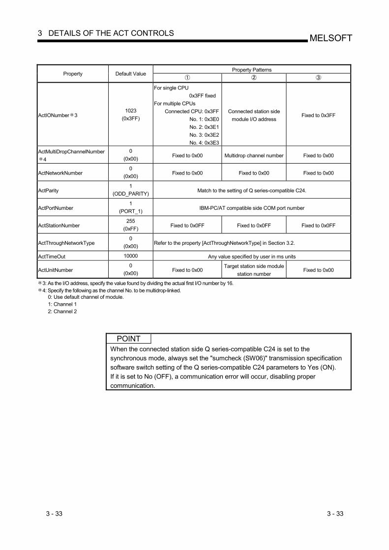
3 - 33 3 - 33
MELSOFT3 DETAILS OF THE ACT CONTROLS
Property Patterns
Property Default Value
ActIONumber 3 1023
(0x3FF)
For single CPU 0x3FF fixed
For multiple CPUs Connected CPU: 0x3FF
No. 1: 0x3E0No. 2: 0x3E1No. 3: 0x3E2No. 4: 0x3E3
Connected station side module I/O address
Fixed to 0x3FF
ActMultiDropChannelNumber 4
0 (0x00) Fixed to 0x00 Multidrop channel number Fixed to 0x00
ActNetworkNumber 0
(0x00) Fixed to 0x00 Fixed to 0x00 Fixed to 0x00
ActParity 1
(ODD_PARITY) Match to the setting of Q series-compatible C24.
ActPortNumber 1
(PORT_1) IBM-PC/AT compatible side COM port number
ActStationNumber 255
(0xFF) Fixed to 0x0FF Fixed to 0x0FF Fixed to 0x0FF
ActThroughNetworkType 0
(0x00) Refer to the property [ActThroughNetworkType] in Section 3.2.
ActTimeOut 10000 Any value specified by user in ms units
ActUnitNumber 0
(0x00) Fixed to 0x00 Target station side module
station number Fixed to 0x00
3: As the I/O address, specify the value found by dividing the actual first I/O number by 16. 4: Specify the following as the channel No. to be multidrop-linked.
0: Use default channel of module. 1: Channel 1 2: Channel 2
POINT When the connected station side Q series-compatible C24 is set to the synchronous mode, always set the "sumcheck (SW06)" transmission specification software switch setting of the Q series-compatible C24 parameters to Yes (ON). If it is set to No (OFF), a communication error will occur, disabling proper communication.

3 - 34 3 - 34
MELSOFT3 DETAILS OF THE ACT CONTROLS
3.3.16 ActAJ71QC24, ActMLAJ71QC24 control
The following table indicates the properties possessed by the ActAJ71QC24, ActMLAJ71QC24 control and their default values. (1) When there is relayed module in addition to connected station side
QC24(N)
(a) Configuration (b) Property patterns Connected
Station CPU Relayed Station CPU
QnACPU Relayed Network
QCPU (Q mode)
QS CPU
QCPU (A mode)
QnA CPU
ACPU1
FXCPU
CC-Link IE Controller Network
MELSECNET/H MELSECNET/10 MELSECNET(II) Ethernet Computer link
IBM-PC/AT compatible
Connected stationCPU
QC24(N)Relayedmodule
Relayed network
Relayed station CPU
Relayedmodule
CC-Link : Accessible (Property pattern within circle) : Inaccessible 1 : Including motion controller CPU
(c) Property list
Property Patterns Property Default Value
3
ActBaudRate 19200
(BAUDRATE_19200) Match to the setting of QC24(N).
ActConnectUnitNumber 0
(0x00) Connected station side module station number
ActControl 8
(TRC_DTR_OR_RTS) Depending on used cable.
ActCpuType 17
(CPU_Q2ACPU) CPU type corresponding to target station
ActIONumber 2 1023
(0x3FF) Fixed to 0x3FF Fixed to 0x3FF Fixed to 0x3FF Connected station side module I/O
address
ActNetworkNumber 0
(0x00) Fixed to 0x00 Target station side module network
number Fixed to 0x00 Fixed to 0x00
ActParity 1
(ODD_PARITY) Match to the setting of QC24(N).
ActPortNumber 1
(PORT_1) IBM-PC/AT compatible side COM port number
ActStationNumber 255
(0xFF) Fixed to 0xFF Target station side
module station number
Target station side module station
number Fixed to 0xFF
ActTimeOut 10000 Any value specified by user in ms units
ActUnitNumber 0
(0x00) Fixed to 0x00 Fixed to 0x00 Fixed to 0x00 Target station side
module station number
2: As the I/O address, specify the value found by dividing the actual first I/O number by 16. 3: Note the following points when making access via the Ethernet module (QE71).
• For ActNetworkNumber and ActStationNumber, specify the value set in the parameter setting of the target station side QE71. • Set the "Station No. IP information" in the parameter setting of the QE71. Also, when making setting, specify other than the
automatic response system (any of the IP address calculation system, table conversion system and combined system) as the "Station No. IP information system".
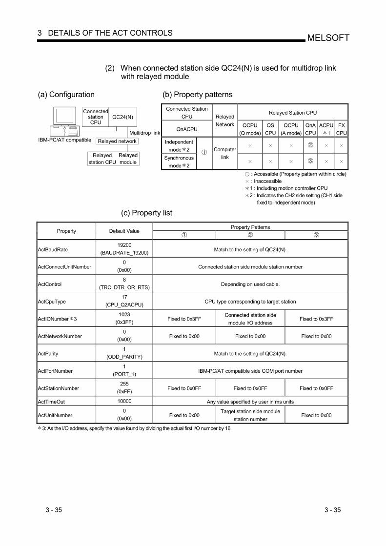
3 - 35 3 - 35
MELSOFT3 DETAILS OF THE ACT CONTROLS
(2) When connected station side QC24(N) is used for multidrop link
with relayed module
(a) Configuration (b) Property patterns
Connected Station CPU
Relayed Station CPU
QnACPU
Relayed Network QCPU
(Q mode)QS
CPU QCPU
(A mode) QnA CPU
ACPU1
FX CPU
Independent mode 2
IBM-PC/AT compatible
Connected stationCPU
QC24(N)
Relayed network
Relayed station CPU
Relayedmodule
Multidrop link
Synchronous mode 2
Computer
link
: Accessible (Property pattern within circle) : Inaccessible 1 : Including motion controller CPU 2 : Indicates the CH2 side setting (CH1 side
fixed to independent mode) (c) Property list
Property Patterns
Property Default Value
ActBaudRate 19200
(BAUDRATE_19200) Match to the setting of QC24(N).
ActConnectUnitNumber 0
(0x00) Connected station side module station number
ActControl 8
(TRC_DTR_OR_RTS) Depending on used cable.
ActCpuType 17
(CPU_Q2ACPU) CPU type corresponding to target station
ActIONumber 3 1023
(0x3FF) Fixed to 0x3FF Connected station side
module I/O address Fixed to 0x3FF
ActNetworkNumber 0
(0x00) Fixed to 0x00 Fixed to 0x00 Fixed to 0x00
ActParity 1
(ODD_PARITY) Match to the setting of QC24(N).
ActPortNumber 1
(PORT_1) IBM-PC/AT compatible side COM port number
ActStationNumber 255
(0xFF) Fixed to 0x0FF Fixed to 0x0FF Fixed to 0x0FF
ActTimeOut 10000 Any value specified by user in ms units
ActUnitNumber 0
(0x00) Fixed to 0x00 Target station side module
station number Fixed to 0x00
3: As the I/O address, specify the value found by dividing the actual first I/O number by 16.

3 - 36 3 - 36
MELSOFT3 DETAILS OF THE ACT CONTROLS
3.3.17 ActAJ71UC24, ActMLAJ71UC24 control
The following table indicates the properties possessed by the ActAJ71UC24, ActMLAJ71UC24 control and their default values. (1) When there is relayed module in addition to connected station side
UC24
(a) Configuration (b) Property patterns Connected Station CPU Relayed Station CPU
QCPU(A mode)
QnACPU
ACPU1
Relayed Network QCPU (Q mode)
QS CPU
QCPU (A mode)
QnA CPU
ACPU1
FX CPU
CC-Link IE Controller Network
MELSECNET/H MELSECNET/10 2 MELSECNET(II) 2 Ethernet Computer link
IBM-PC/ATcompatible
Connected stationCPU
UC24Relayedmodule
Relayed network
Relayed station CPU
Relayedmodule
2
CC-Link
: Accessible (Property pattern within circle) : Inaccessible 1 : Including motion controller CPU 2 : Operates as the one equivalent to AnACPU.
(c) Property list
Property Patterns Property Default Value
ActBaudRate 19200
(BAUDRATE_19200) Match to the setting of UC24.
ActControl 8
(TRC_DTR_OR_RTS) Depending on used cable.
ActCpuType 262
(CPU_A1NCPU) CPU type corresponding to target station
ActDataBits 8
(DATABIT_8) Match to the setting of UC24.
ActNetworkNumber 0
(0x00) Fixed to 0x00 Target station side module
network number Fixed to 0x00
ActParity 1
(ODD_PARITY) Match to the setting of UC24.
ActPortNumber 1
(PORT_1) IBM-PC/AT compatible side COM port number
ActStationNumber 255
(0xFF) Fixed to 0xFF Target station side module
station number Target station side module
station number
ActStopBits 0
(STOPBIT_ONE) Match to the setting of UC24.
ActSumCheck 1
(SUM_CHECK) Match to the setting of UC24.
ActTimeOut 10000 Any value specified by user in ms units
ActUnitNumber 0
(0x00) Target station side module
station number Connected station side module station number
Connected station side module station number
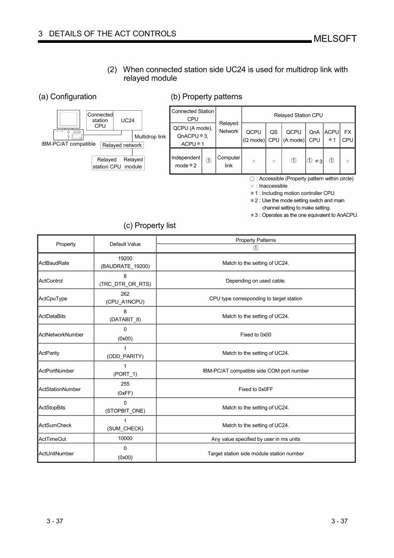
3 - 37 3 - 37
MELSOFT3 DETAILS OF THE ACT CONTROLS
(2) When connected station side UC24 is used for multidrop link with
relayed module
(a) Configuration (b) Property patterns Connected Station
CPU Relayed Station CPU
QCPU (A mode), QnACPU 3,
ACPU 1
Relayed Network QCPU
(Q mode)QS
CPU QCPU
(A mode) QnA CPU
ACPU1
FX CPU
IBM-PC/AT compatible
Connected stationCPU
UC24
Relayed network
Relayed station CPU
Relayedmodule
Multidrop link
Independent mode 2
Computer
link 3
: Accessible (Property pattern within circle) : Inaccessible 1 : Including motion controller CPU 2 : Use the mode setting switch and main
channel setting to make setting. 3 : Operates as the one equivalent to AnACPU.
(c) Property list
Property Patterns Property Default Value
ActBaudRate 19200
(BAUDRATE_19200) Match to the setting of UC24.
ActControl 8
(TRC_DTR_OR_RTS) Depending on used cable.
ActCpuType 262
(CPU_A1NCPU) CPU type corresponding to target station
ActDataBits 8
(DATABIT_8) Match to the setting of UC24.
ActNetworkNumber 0
(0x00) Fixed to 0x00
ActParity 1
(ODD_PARITY) Match to the setting of UC24.
ActPortNumber 1
(PORT_1) IBM-PC/AT compatible side COM port number
ActStationNumber 255
(0xFF) Fixed to 0x0FF
ActStopBits 0
(STOPBIT_ONE) Match to the setting of UC24.
ActSumCheck 1
(SUM_CHECK) Match to the setting of UC24.
ActTimeOut 10000 Any value specified by user in ms units
ActUnitNumber 0
(0x00) Target station side module station number

3 - 38 3 - 38
MELSOFT3 DETAILS OF THE ACT CONTROLS
3.3.18 ActAJ71C24, ActMLAJ71C24 control
The following table indicates the properties possessed by the ActAJ71C24, ActMLAJ71C24 control and their default values. (1) When there is relayed module in addition to connected station side C24
(a) Configuration (b) Property patterns
Connected Station CPU Relayed Station CPU QCPU
(A mode)QnACPU
ACPU1
Relayed Network QCPU (Q mode)
QS CPU
QCPU (A mode)
QnA CPU
ACPU1
FX CPU
CC-Link IE Controller Network
MELSECNET/H MELSECNET/10 2 MELSECNET(II) 2 Ethernet Computer link
IBM-PC/ATcompatible
Connected stationCPU
C24Relayedmodule
Relayed network
Relayed station CPU
Relayedmodule
2
CC-Link
: Accessible (Property pattern within circle) : Inaccessible 1 : Including motion controller CPU 2 : Operates as the one equivalent to AnACPU.
(c) Property list
Property Patterns Property Default Value
4
ActBaudRate 19200
(BAUDRATE_19200) Match to the setting of C24.
ActControl 8
(TRC_DTR_OR_RTS) Depending on used cable.
ActCpuType 262
(CPU_A1NCPU) CPU type corresponding to target station
ActDataBits 8
(DATABIT_8) Match to the setting of C24.
ActParity 1
(ODD_PARITY) Match to the setting of C24.
ActPortNumber 1
(PORT_1) IBM-PC/AT compatible side COM port number
ActStationNumber 3 255
(0xFF) Fixed to 0xFF Target station side module station number
ActStopBits 0
(STOPBIT_ONE) Match to the setting of C24.
ActSumCheck 1
(SUM_CHECK) Match to the setting of C24.
ActTimeOut 10000 Any value specified by user in ms units
ActUnitNumebr 0
(0x00) Target station side module
station number Connected station side module
station number
3: Note the following points depending on whether the connected station side MELSECNET/10 module is the control station or ordinary station. When the connected station side MELSECNET/10 module is the control station... Specify the actual station number of the target station side
MELSECNET/10 module in ActStationNumber. When the connected station side MELSECNET/10 module is the ordinary station... Always set the target station side MELSECNET/10 module
as the control station and specify "0x00" in ActStationNumber.
4: Access via network is enabled only to the network on the side specified in "valid module for another station access" in the connected station side network parameters.

3 - 39 3 - 39
MELSOFT3 DETAILS OF THE ACT CONTROLS
(2) When connected station side C24 is used for multidrop link with
relayed module
(a) Configuration (b) Property patterns Connected Station
CPU Relayed Station CPU
QCPU (A mode), QnACPU 3,
ACPU 1
Relayed Network QCPU
(Q mode)QS
CPU QCPU
(A mode) QnA CPU
ACPU1
FX CPU
IBM-PC/AT compatible
Connected stationCPU
C24
Relayed network
Relayed station CPU
Relayedmodule
Multidrop link
Independent mode 2
Computer
link
3
: Accessible (Property pattern within circle) : Inaccessible 1 : Including motion controller CPU 2 : Use the mode setting switch and main
channel setting to make setting. 3 : Operates as the one equivalent to AnACPU.
(c) Property list
Property Patterns Property Default Value
ActBaudRate 19200
(BAUDRATE_19200) Match to the setting of C24.
ActControl 8
(TRC_DTR_OR_RTS) Depending on used cable.
ActCpuType 262
(CPU_A1NCPU) CPU type corresponding to target station
ActDataBits 8
(DATABIT_8) Match to the setting of C24.
ActParity 1
(ODD_PARITY) Match to the setting of C24.
ActPortNumber 1
(PORT_1) IBM-PC/AT compatible side COM port number
ActStationNumber 255
(0xFF) Fixed to 0x0FF
ActStopBits 0
(STOPBIT_ONE) Match to the setting of C24.
ActSumCheck 1
(SUM_CHECK) Match to the setting of C24.
ActTimeOut 10000 Any value specified by user in ms units
ActUnitNumebr 0
(0x00) Target station side module station number

3 - 40 3 - 40
MELSOFT3 DETAILS OF THE ACT CONTROLS
3.3.19 ActFX485BD, ActMLFX485BD control
The following table indicates the properties possessed by the ActFX485BD, ActMLFX485BD control and their default values.
(1) Configuration
(2) Property patterns
Connected Station CPU
Relayed Station CPU
FXCPU Relayed Network
QCPU(Q mode)
QS CPU
QCPU (A mode)
QnA CPU
ACPU1
FX CPU
CC-Link IE Controller Network
MELSECNET/H MELSECNET/10 MELSECNET(II) Ethernet Computer link
IBM-PC/AT compatible
Connected stationCPU
FX extendedport
Relayed network
Relayed station CPU
Relayedmodule
Multidrop link
CC-Link
: Accessible (Property pattern within circle) : Inaccessible 1 : Including motion controller CPU
(3) Property list
Property Patterns Property Default Value
ActBaudRate 19200
(BAUDRATE_19200) Match to the setting of FX extended port
ActControl 8
(TRC_DTR_OR_RTS) Depending on used cable
ActCpuTimeOut 4 Any value specified by user in 10ms units
ActCpuType 0x205
(CPU_FX2NCPU) CPU type corresponding to target station
ActDataBits 8
(DATABIT_8) Match to the setting of FX extended port
ActParity 1
(ODD_PARITY) Match to the setting of FX extended port
ActPortNumber 0x01
(PORT_1) IBM-PC/AT compatible side COM port number
ActStopBits 0
(STOPBIT_ONE) Match to the setting of FX extended port
ActSumCheck 1(SUM_CHECK) Match to the setting of FX extended port
ActTimeOut 10000 Any value specified by user in ms units
ActUnitNumber 0x00 Target station side module station number

3 - 41 3 - 41
MELSOFT3 DETAILS OF THE ACT CONTROLS
3.3.20 ActFXCPUUSB, ActMLFXCPUUSB control
The following table indicates the properties possessed by the ActFXCPUUSB, ActMLFXCPUUSB control and their default values.
(1) Configuration
(2) Property patterns
Connected Station CPU
Relayed Station CPU
FXCPU Relayed Network
QCPU(Q mode)
QS CPU
QCPU (A mode)
QnA CPU
ACPU1
FX CPU
CC-Link IE Controller Network
MELSECNET/H MELSECNET/10 MELSECNET(II) Ethernet Computer link
IBM-PC/AT compatible
Connected stationCPU
Relayedmodule
Relayed network
Relayed station CPU
Relayedmodule
CC-Link
: Accessible (Property pattern within circle) : Inaccessible 1 : Including motion controller CPU
(3) Property list
Property Patterns Property Default Value
ActCpuType 0x209
(CPU_FX3GCPU) CPU type corresponding to target station
ActTimeOut 10000 Any value specified by user in ms units
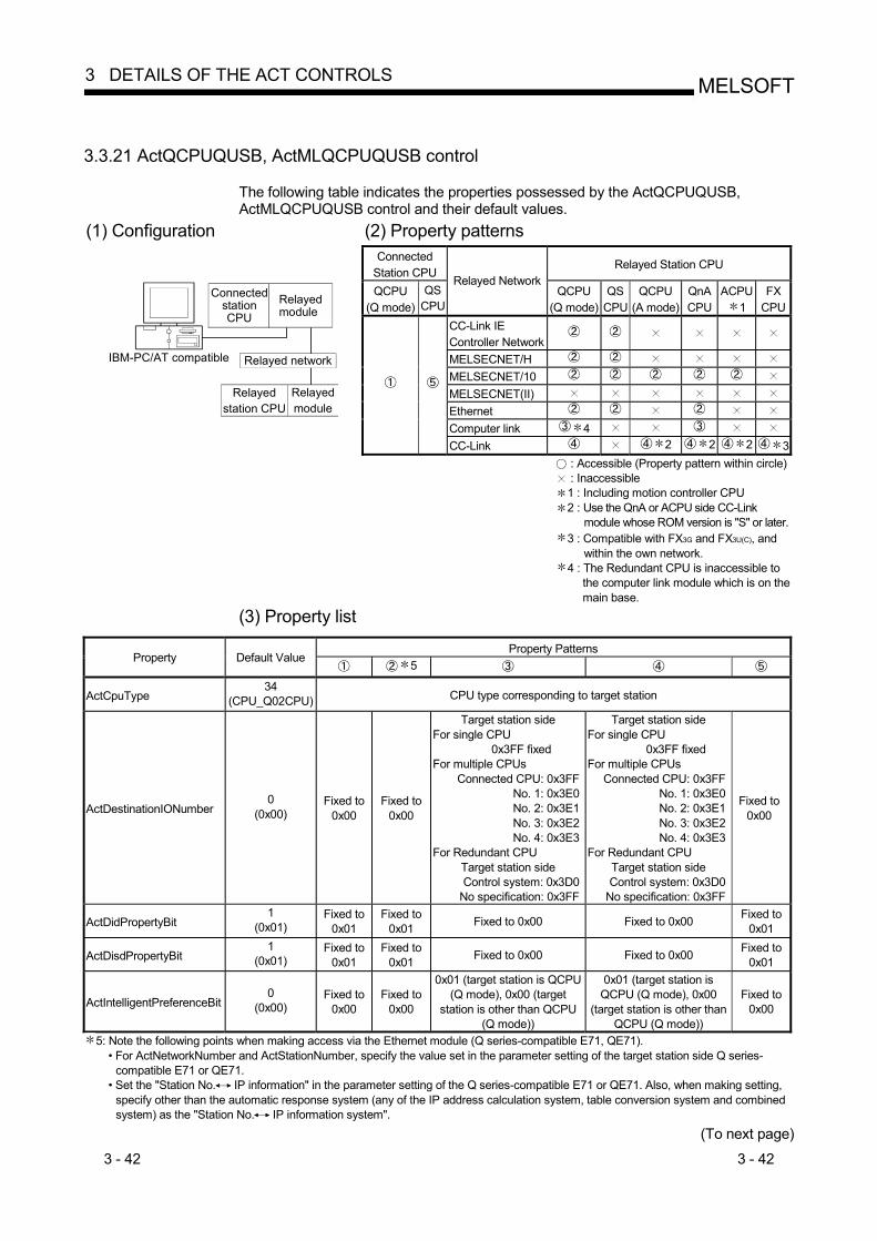
3 - 42 3 - 42
MELSOFT3 DETAILS OF THE ACT CONTROLS
3.3.21 ActQCPUQUSB, ActMLQCPUQUSB control
The following table indicates the properties possessed by the ActQCPUQUSB, ActMLQCPUQUSB control and their default values.
(1) Configuration (2) Property patterns Connected
Station CPU Relayed Station CPU
QCPU (Q mode)
QSCPU
Relayed NetworkQCPU
(Q mode)QS
CPU QCPU
(A mode) QnA CPU
ACPU1
FX CPU
CC-Link IE Controller Network
MELSECNET/H MELSECNET/10 MELSECNET(II) Ethernet Computer link 4
IBM-PC/AT compatible
Connected stationCPU
Relayedmodule
Relayed network
Relayed station CPU
Relayedmodule
CC-Link 2 2 2 3 : Accessible (Property pattern within circle) : Inaccessible 1 : Including motion controller CPU 2 : Use the QnA or ACPU side CC-Link
module whose ROM version is "S" or later. 3 : Compatible with FX3G and FX3U(C), and
within the own network. 4 : The Redundant CPU is inaccessible to
the computer link module which is on the main base.
(3) Property list
Property Patterns Property Default Value
5
ActCpuType 34
(CPU_Q02CPU) CPU type corresponding to target station
ActDestinationIONumber 0
(0x00) Fixed to
0x00 Fixed to
0x00
Target station side For single CPU
0x3FF fixed For multiple CPUs
Connected CPU: 0x3FFNo. 1: 0x3E0No. 2: 0x3E1No. 3: 0x3E2No. 4: 0x3E3
For Redundant CPU Target station side Control system: 0x3D0
No specification: 0x3FF
Target station side For single CPU
0x3FF fixed For multiple CPUs
Connected CPU: 0x3FFNo. 1: 0x3E0No. 2: 0x3E1No. 3: 0x3E2No. 4: 0x3E3
For Redundant CPU Target station side Control system: 0x3D0
No specification: 0x3FF
Fixed to 0x00
ActDidPropertyBit 1
(0x01) Fixed to
0x01 Fixed to
0x01 Fixed to 0x00 Fixed to 0x00 Fixed to 0x01
ActDisdPropertyBit 1
(0x01) Fixed to
0x01 Fixed to
0x01 Fixed to 0x00 Fixed to 0x00 Fixed to 0x01
ActIntelligentPreferenceBit 0
(0x00) Fixed to
0x00 Fixed to
0x00
0x01 (target station is QCPU (Q mode), 0x00 (target
station is other than QCPU (Q mode))
0x01 (target station is QCPU (Q mode), 0x00
(target station is other than QCPU (Q mode))
Fixed to 0x00
5: Note the following points when making access via the Ethernet module (Q series-compatible E71, QE71). • For ActNetworkNumber and ActStationNumber, specify the value set in the parameter setting of the target station side Q series-
compatible E71 or QE71. • Set the "Station No. IP information" in the parameter setting of the Q series-compatible E71 or QE71. Also, when making setting,
specify other than the automatic response system (any of the IP address calculation system, table conversion system and combined system) as the "Station No. IP information system".
(To next page)

3 - 43 3 - 43
MELSOFT3 DETAILS OF THE ACT CONTROLS
Property Patterns
Property Default Value 7
ActIONumber 6 1023
(0x3FF)
For single CPU
0x3FF fixed For multiple CPUs Connected CPU: 0x3FF
No. 1: 0x3E0No. 2: 0x3E1No. 3: 0x3E2No. 4: 0x3E3
For Redundant CPU Target station side
Control system: 0x3D0No specification: 0x3FF
Target station side For single CPU
0x3FF fixed For multiple CPUs Connected CPU: 0x3FF
No. 1: 0x3E0No. 2: 0x3E1No. 3: 0x3E2No. 4: 0x3E3
For Redundant CPU Target station side
Control system: 0x3D0No specification: 0x3FF
Connected station side module I/O
address
Connected station side module I/O
address
Connected CPU: 0x3FF
ActMultiDropChannelNumber8
0 (0x00) Fixed to 0x00 Fixed to 0x00
Multidrop channel number
Fixed to 0x00 Fixed to 0x00
ActNetworkNumber 0
(0x00) Fixed to 0x00 Target station side
module network numberFixed to 0x00 Fixed to 0x00 Fixed to 0x00
ActStationNumber 255
(0xFF) Fixed to 0xFF Target station side
module station number Fixed to 0xFF Fixed to 0xFF Fixed to 0xFF
ActThroughNetworkType 0
(0x00) Refer to the property [ActThroughNetworkType] in Section 3.2. Fixed to 0x00
ActTimeOut 10000 Any value specified by user in ms units
ActUnitNumber 0
(0x00) Fixed to 0x00 Fixed to 0x00 Target station side module
station number
Target station side module
station number Fixed to 0x00
6: As the I/O address, specify the value found by dividing the actual first I/O number by 16. 7: Note the following points when making access via the Ethernet module (Q series-compatible E71, QE71).
• For ActNetworkNumber and ActStationNumber, specify the value set in the parameter setting of the target station side Q series-compatible E71 or QE71.
• Set the "Station No. IP information" in the parameter setting of the Q series-compatible E71 or QE71. Also, when making setting, specify other than the automatic response system (any of the IP address calculation system, table conversion system and combined system) as the "Station No. IP information system".
8: Specify the following as the channel No. to be multidrop-linked. 0: Use default channel of module. 1: Channel 1 2: Channel 2

3 - 44 3 - 44
MELSOFT3 DETAILS OF THE ACT CONTROLS
3.3.22 ActCCG4Q, ActMLCCG4Q control
The following table indicates the properties possessed by the ActCCG4Q, ActMLCCG4Q control and their default values. (1) Configuration
CC-Link G4 module
(QnA mode)IBM-PC/ATcompatible
Connected station CPU CC-Link module
Relayedmodule
Relayed network
Relayed station CPU
Relayedmodule
(2) Property patterns Connected
Station CPU Relayed Station CPU
QCPU (Q mode)
Relayed NetworkQCPU
(Q mode)QS
CPUQCPU
(A mode)QnACPU
ACPU1
FX CPU
CC-Link IE Controller Network
MELSECNET/H MELSECNET/10 MELSECNET(II) Ethernet Computer link
CC-Link : Accessible (Property pattern within circle) : Inaccessible 1 : Including motion controller CPU

3 - 45 3 - 45
MELSOFT3 DETAILS OF THE ACT CONTROLS
(3) Property list
Property Patterns Property Default Value
3
ActBaudRate 19200
(BAUDRATE_19200) BAUDRATE_9600, BAUDRATE_19200, BAUDRATE_38400,
BAUDRATE_57600, BAUDRATE_115200
ActConnectUnitNumber 0
(0x00) Connected station side module station number
ActControl 8
(TRC_DTR_OR_RTS) Depending on used cable.
ActCpuType 34
(CPU_Q2CPU) CPU type corresponding to target station
ActIONumber 2 1023
(0x3FF)
Target station side For single CPU
0x3FF fixed For multiple CPUs
Connected CPU: 0x3FFNo. 1: 0x3E0No. 2: 0x3E1No. 3: 0x3E2No. 4: 0x3E3
For Redundant CPU Control system: 0x3D0
No specification: 0x3FF
Target station side For single CPU
0x3FF fixed For multiple CPUs
Connected CPU: 0x3FF No. 1: 0x3E0 No. 2: 0x3E1 No. 3: 0x3E2 No. 4: 0x3E3
For Redundant CPU Target station side Control system: 0x3D0
No specification: 0x3FF
Connected station side relayed module I/O
address
ActNetworkNumber 0
(0x00) Fixed to 0x00 Target station side module network number Fixed to 0x00
ActPortNumber 1
(PORT_1) IBM-PC/AT compatible side COM port number
ActStationNumber 255
(0xFF) Fixed to 0xFF Target station side module station number Fixed to 0xFF
ActThroughNetworkType 0
(0x00) Refer to the property [ActThroughNetworkType] in Section 3.2.
ActTimeOut 10000 Any value specified by user in ms units
ActUnitNumber 0
(0x00) Fixed to 0x00 Fixed to 0x00 Target station side module station number
2: As the I/O address, specify the value found by dividing the actual first I/O number by 16. 3: Note the following points when making access via the Ethernet module (QE71).
• For ActNetworkNumber and ActStationNumber, specify the value set in the parameter setting of the target station side QE71. • Set the "Station No. IP information" in the parameter setting of the QE71. Also, when making setting, specify other than the
automatic response system (any of the IP address calculation system, table conversion system and combined system) as the "Station No. IP information system".

3 - 46 3 - 46
MELSOFT3 DETAILS OF THE ACT CONTROLS
3.3.23 ActCCG4QnA, ActMLCCG4QnA control
The following table indicates the properties possessed by the ActCCG4QnA, ActMLCCG4QnA control and their default values.
(1) Configuration
CC-Link G4 module
(QnA mode)IBM-PC/ATcompatible
Connected station CPU CC-Link module
Relayedmodule
Relayed network
Relayed station CPU
Relayedmodule
(2) Property patterns Connected
Station CPU Relayed Station CPU
QnACPU
Relayed Network QCPU
(Q mode) QS
CPU QCPU
(A mode) QnA CPU
ACPU 1
FX CPU
CC-Link IE Controller Network
MELSECNET/H MELSECNET/10 MELSECNET(II) Ethernet Computer link
CC-Link
: Accessible (Property pattern within circle) : Inaccessible 1 : Including motion controller CPU
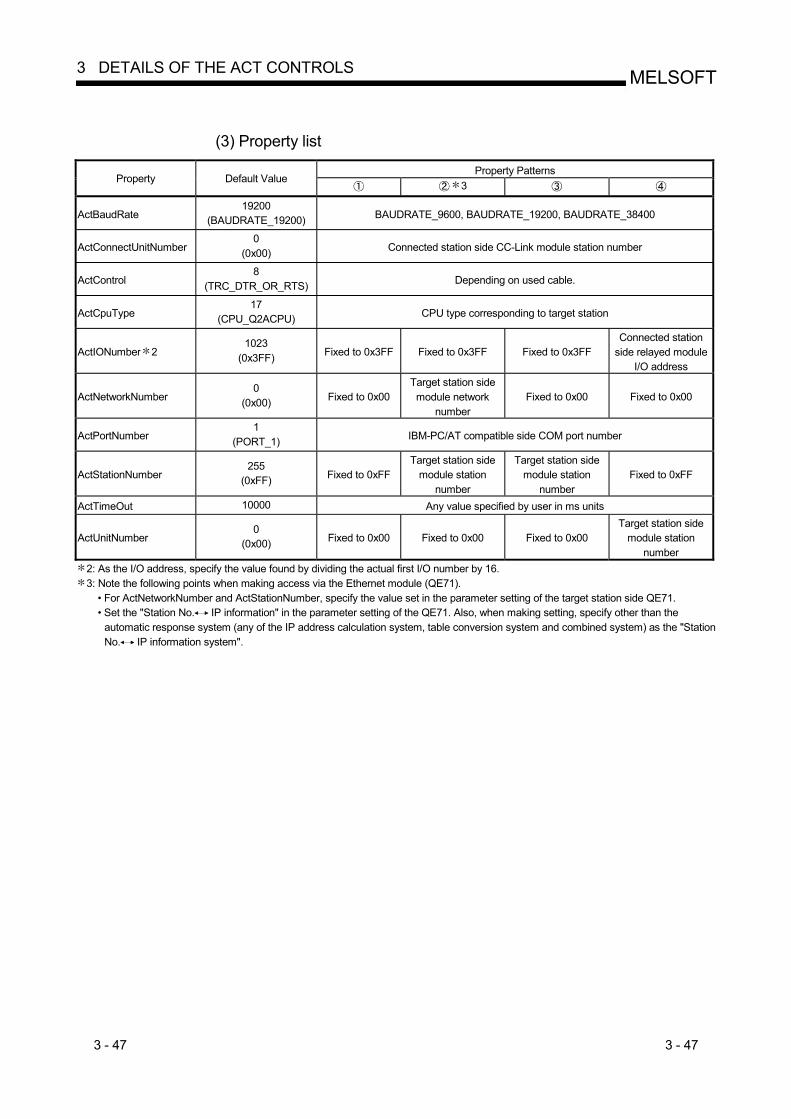
3 - 47 3 - 47
MELSOFT3 DETAILS OF THE ACT CONTROLS
(3) Property list
Property Patterns
Property Default Value 3
ActBaudRate 19200
(BAUDRATE_19200) BAUDRATE_9600, BAUDRATE_19200, BAUDRATE_38400
ActConnectUnitNumber 0
(0x00) Connected station side CC-Link module station number
ActControl 8
(TRC_DTR_OR_RTS) Depending on used cable.
ActCpuType 17
(CPU_Q2ACPU) CPU type corresponding to target station
ActIONumber 2 1023
(0x3FF) Fixed to 0x3FF Fixed to 0x3FF Fixed to 0x3FF Connected station
side relayed module I/O address
ActNetworkNumber 0
(0x00) Fixed to 0x00 Target station side module network
number Fixed to 0x00 Fixed to 0x00
ActPortNumber 1
(PORT_1) IBM-PC/AT compatible side COM port number
ActStationNumber 255
(0xFF) Fixed to 0xFF Target station side
module station number
Target station side module station
number Fixed to 0xFF
ActTimeOut 10000 Any value specified by user in ms units
ActUnitNumber 0
(0x00) Fixed to 0x00 Fixed to 0x00 Fixed to 0x00 Target station side
module station number
2: As the I/O address, specify the value found by dividing the actual first I/O number by 16. 3: Note the following points when making access via the Ethernet module (QE71).
• For ActNetworkNumber and ActStationNumber, specify the value set in the parameter setting of the target station side QE71. • Set the "Station No. IP information" in the parameter setting of the QE71. Also, when making setting, specify other than the
automatic response system (any of the IP address calculation system, table conversion system and combined system) as the "Station No. IP information system".
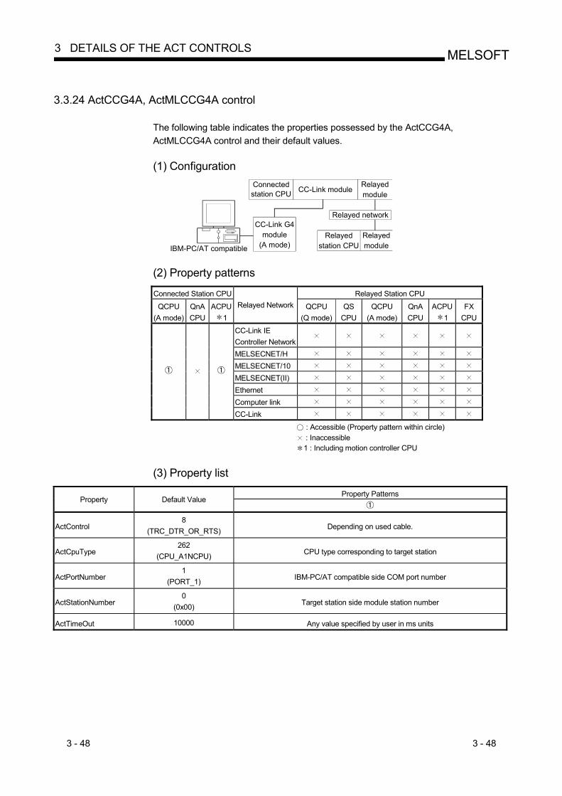
3 - 48 3 - 48
MELSOFT3 DETAILS OF THE ACT CONTROLS
3.3.24 ActCCG4A, ActMLCCG4A control
The following table indicates the properties possessed by the ActCCG4A, ActMLCCG4A control and their default values.
(1) Configuration
CC-Link G4 module
(A mode)IBM-PC/AT compatible
Connected station CPU CC-Link module
Relayedmodule
Relayed network
Relayed station CPU
Relayedmodule
(2) Property patterns
Connected Station CPU Relayed Station CPU
QCPU (A mode)
QnA CPU
ACPU1
Relayed Network QCPU (Q mode)
QS CPU
QCPU (A mode)
QnA CPU
ACPU 1
FX CPU
CC-Link IE Controller Network
MELSECNET/H MELSECNET/10 MELSECNET(II) Ethernet Computer link
CC-Link
: Accessible (Property pattern within circle) : Inaccessible 1 : Including motion controller CPU
(3) Property list
Property Patterns
Property Default Value
ActControl 8
(TRC_DTR_OR_RTS) Depending on used cable.
ActCpuType 262
(CPU_A1NCPU) CPU type corresponding to target station
ActPortNumber 1
(PORT_1) IBM-PC/AT compatible side COM port number
ActStationNumber 0
(0x00) Target station side module station number
ActTimeOut 10000 Any value specified by user in ms units

3 - 49 3 - 49
MELSOFT3 DETAILS OF THE ACT CONTROLS
3.3.25 ActMnet10BD, ActMLMnet10BD control
The following table indicates the properties possessed by the ActMnet10BD, ActMLMnet10BD control and their default values. (1) When connected station CPU is QCPU (Q mode)
(a) Configuration
IBM-PC/AT compatible
Connected station CPU
MELSECNET/10module
Relayedmodule
Relayed network
Relayed station CPU
Relayedmodule
(b) Property patterns
Connected
Station CPURelayed Station CPU
Own Board QCPU
(Q mode)
Relayed NetworkQCPU
(Q mode)QS
CPUQCPU
(A mode) QnA CPU
ACPU1
FX CPU
CC-Link IE Controller Network
MELSECNET/H MELSECNET/10 MELSECNET(II) Ethernet Computer link 2
CC-Link : Accessible (Property pattern within circle) : Inaccessible 1 : Including motion controller CPU 2 : The Redundant CPU is inaccessible to the computer
link module which is on the main base. (c) Property list
Property Patterns Property Default Value
ActCpuType 1025
(CPU_BOARD) CPU type corresponding to target station
ActDestinationIONumber 0
(0x00) Fixed to 0x00 Fixed to 0x00
Target station side For single CPU
0x3FF fixed For multiple CPUs Connected CPU: 0x3FF
No. 1: 0x3E0 No. 2: 0x3E1 No. 3: 0x3E2 No. 4: 0x3E3
For Redundant CPU 0x3FF fixed
Target station side For single CPU
0x3FF fixed For multiple CPUs
Connected CPU: 0x3FFNo. 1: 0x3E0No. 2: 0x3E1No. 3: 0x3E2No. 4: 0x3E3
For Redundant CPU 0x3FF fixed
ActDidPropertyBit 0
(0x00) Fixed to 0x00 Fixed to 0x01 Fixed to 0x00 Fixed to 0x00
(To next page)

3 - 50 3 - 50
MELSOFT3 DETAILS OF THE ACT CONTROLS
Property Patterns
Property Default Value
ActDsidPropertyBit 0
(0x00) Fixed to 0x00 Fixed to 0x01 Fixed to 0x00 Fixed to 0x00
ActIONumber 3 0
(0x00) Fixed to 0x00
For single CPU 0x3FF fixed
For multiple CPUs Connected CPU: 0x3FF
No. 1: 0x3E0No. 2: 0x3E1No. 3: 0x3E2No. 4: 0x3E3
For Redundant CPU 0x3FF fixed
Connected station side relayed module I/O
address
Connected station side relayed module I/O
address
ActMultiDropChannelNumber 4
0 (0x00) Fixed to 0x00 Fixed to 0x00
Multidrop channel number
Fixed to 0x00
ActNetworkNumber 0
(0x00) Fixed to 0x00 Target station side
module network number
Connected station side module network
number
Connected station side module network
number
ActPortNumber 1
(PORT_1) Board No. of IBM-PC/AT compatible side MELSECNET/10 board,
PORT 1 to PORT 4 (first to fourth boards)
ActStationNumber 255
(0xFF) Fixed to 0xFF Target station side
module station number Connected station side module station number
Connected station side module station number
ActUnitNumber 0
(0x00) Fixed to 0x00 Fixed to 0x00 Target station side
module station number Target station side
module station number
3 : As the I/O address, specify the value found by dividing the actual first I/O number by 16. 4 : Specify the following as the channel No. to be multidrop-linked.
0: Use default channel of module. 1: Channel 1 2: Channel 2

3 - 51 3 - 51
MELSOFT3 DETAILS OF THE ACT CONTROLS
(2) When connected station CPU is QCPU (A mode) or ACPU
(a) Configuration
IBM-PC/AT compatible
Connected station CPU
MELSECNET/10module
Relayedmodule
Relayed network
Relayed station CPU
Relayedmodule
(b) Property patterns
Connected Station CPU Relayed Station CPU Own Board QCPU (A mode) ACPU 1
Relayed NetworkQCPU (Q mode) QSCPU QCPU (A mode) QnACPU ACPU 1 FXCPU
CC-Link IE Controller Network
MELSECNET/H MELSECNET/10 MELSECNET(II) Ethernet Computer link
CC-Link : Accessible (Property pattern within circle) : Inaccessible 1 : Including motion controller CPU
(c) Property list
Property Patterns Property Default Value
ActCpuType 1025
(CPU_BOARD) CPU type corresponding to target station
ActDestinationIONumber 0
(0x00) Fixed to 0x00
ActDidPropertyBit 0
(0x00) Fixed to 0x00 Fixed to 0x01 Fixed to 0x00
ActDsidPropertyBit 0
(0x00) Fixed to 0x00 Fixed to 0x01 Fixed to 0x00
ActIONumber 2 0
(0x00) Fixed to 0x00
Target station side For single CPU
0x3FF fixed For multiple CPUs
Connected CPU: 0x3FF No. 1: 0x3E0 No. 2: 0x3E1 No. 3: 0x3E2 No. 4: 0x3E3
For Redundant CPU 0x3FF fixed
Fixed to 0x3FF
ActMultiDropChannelNumber 0
(0x00) Fixed to 0x00
ActNetworkNumber 0
(0x00) Fixed to 0x00 Target station side module network number
ActPortNumber 1
(PORT_1) Board No. of IBM-PC/AT compatible side MELSECNET/10 board,
PORT 1 to PORT 4 (first to fourth boards)
ActStationNumber 255
(0xFF) Fixed to 0xFF Target station side module station number
ActUnitNumber 0
(0x00) Fixed to 0x00
2: As the I/O address, specify the value found by dividing the actual first I/O number by 16.

3 - 52 3 - 52
MELSOFT3 DETAILS OF THE ACT CONTROLS
(3) When connected station CPU is QnACPU
(a) Configuration
IBM-PC/AT compatible
Connected station CPU
MELSECNET/10module
Relayedmodule
Relayed network
Relayed station CPU
Relayedmodule
(b) Property patterns
Connected Station CPU Relayed Station CPU Own Board QnACPU
Relayed Network QCPU (Q mode) QSCPU QCPU (A mode) QnACPU ACPU 1 FXCPU
CC-Link IE Controller Network
MELSECNET/H MELSECNET/10 MELSECNET(II) Ethernet Computer link
CC-Link : Accessible (Property pattern within circle) : Inaccessible 1 : Including motion controller CPU
(c) Property list
Property Patterns Property Default Value
ActCpuType 1025
(CPU_BOARD) CPU type corresponding to target station
ActDestinationIONumber 0
(0x00) Fixed to 0x00
ActDidPropertyBit 0
(0x00) Fixed to 0x00 Fixed to 0x01 Fixed to 0x00
ActDsidPropertyBit 0
(0x00) Fixed to 0x00 Fixed to 0x01 Fixed to 0x00
ActIONumber 2 0
(0x00) Fixed to 0x00 Fixed to 0x3FF
Target station side For single CPU
0x3FF fixed For multiple CPUs
Connected CPU: 0x3FF No. 1: 0x3E0 No. 2: 0x3E1 No. 3: 0x3E2 No. 4: 0x3E3
For Redundant CPU 0x3FF fixed
Connected station side relayed module
I/O address
ActMultiDropChannelNumber 0
(0x00) Fixed to 0x00 Multidrop channel number
ActNetworkNumber 0
(0x00) Fixed to 0x00 Target station side
module network number
Target station side module network number
Connected station side module network
number
ActPortNumber 1
(PORT_1) Board No. of IBM-PC/AT compatible side MELSECNET/10 board,
PORT 1 to PORT 4 (first to fourth boards)
ActStationNumber 255
(0xFF) Fixed to 0xFF Target station side
module station number
Target station side module station number
Connected station side module station
number
ActUnitNumber 0
(0x00) Fixed to 0x00 Fixed to 0x00 Fixed to 0x00 Target station side
module station number
2: As the I/O address, specify the value found by dividing the actual first I/O number by 16.

3 - 53 3 - 53
MELSOFT3 DETAILS OF THE ACT CONTROLS
3.3.26 ActMnetHBD, ActMLMnetHBD control
The following table indicates the properties possessed by the ActMnetHBD, ActMLMnetHBD control and their default values. (1) When access is made via MELSECNET/H mode using QCPU (Q
mode) as connected station CPU (a) Configuration
IBM-PC/AT compatible
Connected station CPU
MELSECNET/Hmodule
Relayedmodule
Relayed network
Relayed station CPU
Relayedmodule
(b) Property patterns
Connected Station CPU Relayed Station CPU Own Board QCPU (Q mode) QSCPU
Relayed Network QCPU (Q mode) QSCPU QCPU (A mode) QnACPU ACPU 1 FXCPU
CC-Link IE Controller Network
MELSECNET/H MELSECNET/10 MELSECNET(II) Ethernet Computer link 3
2
CC-Link : Accessible (Property pattern within circle) : Inaccessible 1 : Including motion controller CPU 2 : Relayed stations cannot be accessed through the QSCPU. 3 : The Redundant CPU is inaccessible to the computer link
module which is on the main base. (c) Property list
Property Patterns Property Default Value
ActCpuType 1025
(CPU_BOARD) CPU type corresponding to target station
ActDestinationIONumber 0
(0x00) Fixed to 0x00 Fixed to 0x00
Target station side For single CPU
0x3FF fixed For multiple CPUs
Connected CPU: 0x3FF No. 1: 0x3E0 No. 2: 0x3E1 No. 3: 0x3E2 No. 4: 0x3E3
For Redundant CPU Target station side
Control system: 0x3D0 No specification: 0x3FF
Target station side For single CPU
0x3FF fixed For multiple CPUs
Connected CPU: 0x3FFNo. 1: 0x3E0No. 2: 0x3E1No. 3: 0x3E2No. 4: 0x3E3
For Redundant CPU Target station side
Control system: 0x3D0No specification: 0x3FF
(To next page)
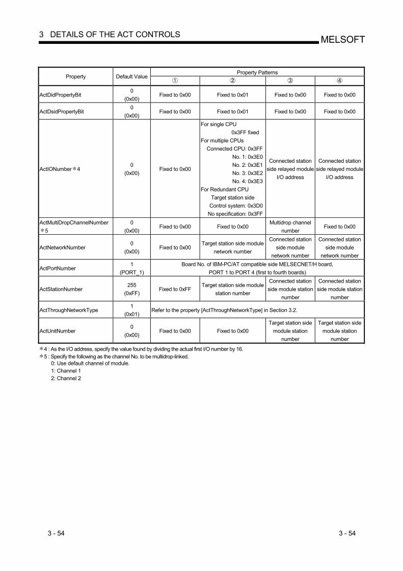
3 - 54 3 - 54
MELSOFT3 DETAILS OF THE ACT CONTROLS
Property Patterns
Property Default Value
ActDidPropertyBit 0
(0x00) Fixed to 0x00 Fixed to 0x01 Fixed to 0x00 Fixed to 0x00
ActDsidPropertyBit 0
(0x00) Fixed to 0x00 Fixed to 0x01 Fixed to 0x00 Fixed to 0x00
ActIONumber 4 0
(0x00) Fixed to 0x00
For single CPU 0x3FF fixed
For multiple CPUs Connected CPU: 0x3FF
No. 1: 0x3E0No. 2: 0x3E1No. 3: 0x3E2No. 4: 0x3E3
For Redundant CPU Target station side
Control system: 0x3D0No specification: 0x3FF
Connected station side relayed module
I/O address
Connected station side relayed module
I/O address
ActMultiDropChannelNumber 5
0 (0x00)
Fixed to 0x00 Fixed to 0x00 Multidrop channel
number Fixed to 0x00
ActNetworkNumber 0
(0x00) Fixed to 0x00
Target station side module network number
Connected station side module
network number
Connected station side module
network number
ActPortNumber 1
(PORT_1) Board No. of IBM-PC/AT compatible side MELSECNET/H board,
PORT 1 to PORT 4 (first to fourth boards)
ActStationNumber 255
(0xFF) Fixed to 0xFF
Target station side module station number
Connected station side module station
number
Connected station side module station
number
ActThroughNetworkType 1
(0x01) Refer to the property [ActThroughNetworkType] in Section 3.2.
ActUnitNumber 0
(0x00) Fixed to 0x00 Fixed to 0x00
Target station side module station
number
Target station side module station
number 4 : As the I/O address, specify the value found by dividing the actual first I/O number by 16. 5 : Specify the following as the channel No. to be multidrop-linked.
0: Use default channel of module. 1: Channel 1 2: Channel 2

3 - 55 3 - 55
MELSOFT3 DETAILS OF THE ACT CONTROLS
(2) When access is made via MELSECNET/10 mode using QCPU (Q
mode) as connected station CPU Operates when both the MELSECNET/H board and relayed module are in the MELSECNET/10 mode.
(a) Configuration
IBM-PC/AT compatible
Connected station CPU
MELSECNET/Hmodule
Relayedmodule
Relayed network
Relayed station CPU
Relayedmodule
(b) Property patterns
Connected Station CPU Relayed Station CPU Own
Board QCPU (Q mode) QSCPURelayed Network
QCPU (Q mode) QSCPU QCPU (A mode) QnACPU ACPU 1 FXCPU
CC-Link IE Controller Network
MELSECNET/H MELSECNET/10 MELSECNET(II) Ethernet Computer link 3
2
CC-Link : Accessible (Property pattern within circle) : Inaccessible 1 : Including motion controller CPU 2 : Relayed stations cannot be accessed through the QSCPU. 3 : The Redundant CPU is inaccessible to the computer link
module which is on the main base.
(c) Property list
Property Patterns Property Default Value
ActCpuType 1025
(CPU_BOARD) CPU type corresponding to target station
ActDestinationIONumber 0
(0x00) Fixed to 0x00 Fixed to 0x00
Target station side For single CPU
0x3FF fixed For multiple CPUs
Connected CPU: 0x3FF No. 1: 0x3E0 No. 2: 0x3E1 No. 3: 0x3E2 No. 4: 0x3E3
For Redundant CPU Target station side
Control system: 0x3D0 No specification: 0x3FF
Target station side For single CPU
0x3FF fixed For multiple CPUs
Connected CPU: 0x3FFNo. 1: 0x3E0No. 2: 0x3E1No. 3: 0x3E2No. 4: 0x3E3
For Redundant CPU Target station side
Control system: 0x3D0No specification: 0x3FF
(To next page)

3 - 56 3 - 56
MELSOFT3 DETAILS OF THE ACT CONTROLS
Property Patterns
Property Default Value
ActDidPropertyBit 0
(0x00) Fixed to 0x00 Fixed to 0x01 Fixed to 0x00 Fixed to 0x00
ActDsidPropertyBit 0
(0x00) Fixed to 0x00 Fixed to 0x01 Fixed to 0x00 Fixed to 0x00
ActIONumber 4 0
(0x00) Fixed to 0x00
For single CPU 0x3FF fixed
For multiple CPUs Connected CPU: 0x3FF
No. 1: 0x3E0No. 2: 0x3E1No. 3: 0x3E2No. 4: 0x3E3
For Redundant CPU Target station side Control system: 0x3D0
No specification: 0x3FF
Connected station side relayed
module I/O address
Connected station side relayed
module I/O address
ActMultiDropChannelNumber5
0 (0x00) Fixed to 0x00 Fixed to 0x00
Multidrop channel number
Fixed to 0x00
ActNetworkNumber 0
(0x00) Fixed to 0x00 Target station side module
network number
Connected station side module
network number
Connected station side module
network number
ActPortNumber 1
(PORT_1) Board No. of IBM-PC/AT compatible side MELSECNET/H board,
PORT 1 to PORT 4 (first to fourth boards)
ActStationNumber 255
(0xFF) Fixed to 0xFF Target station side module
station number
Connected station side module station
number
Connected station side module station
number
ActThroughNetworkType 1
(0x01) Fixed to 0x01
ActUnitNumber 0
(0x00) Fixed to 0x00 Fixed to 0x00 Target station side
module station number
Target station side module station
number 4 : As the I/O address, specify the value found by dividing the actual first I/O number by 16. 5 : Specify the following as the channel No. to be multidrop-linked.
0: Use default channel of module. 1: Channel 1 2: Channel 2

3 - 57 3 - 57
MELSOFT3 DETAILS OF THE ACT CONTROLS
(3) When access is made via MELSECNET/10 mode using QCPU (A
mode) or ACPU as connected station CPU Operates when the MELSECNET/H board is in the MELSECNET/10 mode. (a) Configuration
IBM-PC/AT compatible
Connected station CPU
MELSECNET/Hmodule
Relayedmodule
Relayed network
Relayed station CPU
Relayedmodule
(b) Property patterns
Connected Station CPU Relayed Station CPU Own Board QCPU (A mode) ACPU 1
Relayed Network QCPU (Q mode) QSCPU QCPU (A mode) QnACPU ACPU 1 FXCPU
CC-Link IE Controller Network
MELSECNET/H MELSECNET/10 MELSECNET(II) Ethernet Computer link
CC-Link : Accessible (Property pattern within circle) : Inaccessible 1 : Including motion controller CPU
(c) Property list Property Patterns Property Default Value
ActCpuType 1025 (CPU_BOARD) CPU type corresponding to target station
ActDestinationIONumber 0 (0x00) Fixed to 0x00
ActDidPropertyBit 0 (0x00) Fixed to 0x00 Fixed to 0x01 Fixed to 0x00
ActDsidPropertyBit 0 (0x00) Fixed to 0x00 Fixed to 0x01 Fixed to 0x00
ActIONumber 0 (0x00) Fixed to 0x00
Target station side For single CPU
0x3FF fixed For multiple CPUs
Connected CPU: 0x3FF No. 1: 0x3E0 No. 2: 0x3E1 No. 3: 0x3E2 No. 4: 0x3E3
For Redundant CPU Target station side Control system: 0x3D0
No specification: 0x3FF
Fixed to 0x3FF
ActMultiDropChannelNumber 0 (0x00) Fixed to 0x00
ActNetworkNumber 0 (0x00) Fixed to 0x00 Target station side module network number
ActPortNumber 1 (PORT_1)
Board No. of IBM-PC/AT compatible side MELSECNET/H board, PORT 1 to PORT 4 (first to fourth boards)
ActStationNumber 255 (0xFF) Fixed to 0xFF Target station side module station number
ActThroughNetworkType 1 (0x01) Fixed to 0x01
ActUnitNumber 0 (0x00) Fixed to 0x00

3 - 58 3 - 58
MELSOFT3 DETAILS OF THE ACT CONTROLS
(4) When access is made via MELSECNET/10 mode using QnACPU
as connected station CPU Operates when the MELSECNET/H board is in the MELSECNET/10 mode. (a) Configuration
IBM-PC/AT compatible
Connected station CPU
MELSECNET/Hmodule
Relayedmodule
Relayed network
Relayed station CPU
Relayedmodule
(b) Property patterns
Connected Station CPU Relayed Station CPU Own Board QnACPU
Relayed Network QCPU (Q mode) QSCPU QCPU (A mode) QnACPU ACPU 1 FXCPU
CC-Link IE Controller Network
MELSECNET/H MELSECNET/10 MELSECNET(II) Ethernet Computer link
CC-Link : Accessible (Property pattern within circle) : Inaccessible 1 : Including motion controller CPU
(c) Property list
Property Patterns Property Default Value 2
ActCpuType 1025
(CPU_BOARD) CPU type corresponding to target station
ActDestinationIONumber 0
(0x00) Fixed to 0x00
ActDidPropertyBit 0
(0x00) Fixed to 0x00 Fixed to 0x01 Fixed to 0x00
ActDsidPropertyBit 0
(0x00) Fixed to 0x00 Fixed to 0x01 Fixed to 0x00
ActIONumber 3 0
(0x00) Fixed to 0x00 Fixed to 0x3FF
Target station side For single CPU
0x3FF fixed For multiple CPUs
Connected CPU: 0x3FF No. 1: 0x3E0 No. 2: 0x3E1 No. 3: 0x3E2 No. 4: 0x3E3
For Redundant CPU Target station side Control system: 0x3D0
No specification: 0x3FF
Connected station side relayed
module I/O address
2: Note the following for access to be made via the Ethernet module (Q series-compatible E71, QE71). • Specify ActNetworkNumber and ActStationNumber using the values set in the target station side Q series-compatible E71 or QE71. • Set "Station No. IP information" in the Q series-compatible E71 or QE71 parameter setting. When making setting, specify other
than the automatic response system (any of the IP address calculation system, table conversion system and combined system) as the "Station No. IP information system".
3: As the I/O address, specify the value found by dividing the actual first I/O number by 16. (To next page)

3 - 59 3 - 59
MELSOFT3 DETAILS OF THE ACT CONTROLS
Property Patterns
Property Default Value 4
ActMultiDropChannelNumber5
0 (0x00) Fixed to 0x00
Multidrop channel number
ActNetworkNumber 0
(0x00) Fixed to 0x00 Target station side module network
number
Target station side module network
number
Connected station side module network
number
ActPortNumber 1
(PORT_1) Board No. of IBM-PC/AT compatible side MELSECNET/H board,
PORT 1 to PORT 4 (first to fourth boards)
ActStationNumber 255
(0xFF) Fixed to 0xFF Target station side
module station number
Target station side module station
number
Connected station side module station
number
ActThroughNetworkType 1
(0x01) Fixed to 0x01
ActUnitNumber 0
(0x00) Fixed to 0x00 Fixed to 0x00 Fixed to 0x00 Target station side
module station number
4: Note the following for access to be made via the Ethernet module (Q series-compatible E71, QE71). • Specify ActNetworkNumber and ActStationNumber using the values set in the target station side Q series-compatible E71 or QE71. • Set "Station No. IP information" in the Q series-compatible E71 or QE71 parameter setting. When making setting, specify other
than the automatic response system (any of the IP address calculation system, table conversion system and combined system) as the "Station No. IP information system".
5: Specify the following as the channel No. to be multidrop-linked. 0: Use default channel of module. 1: Channel 1 2: Channel 2
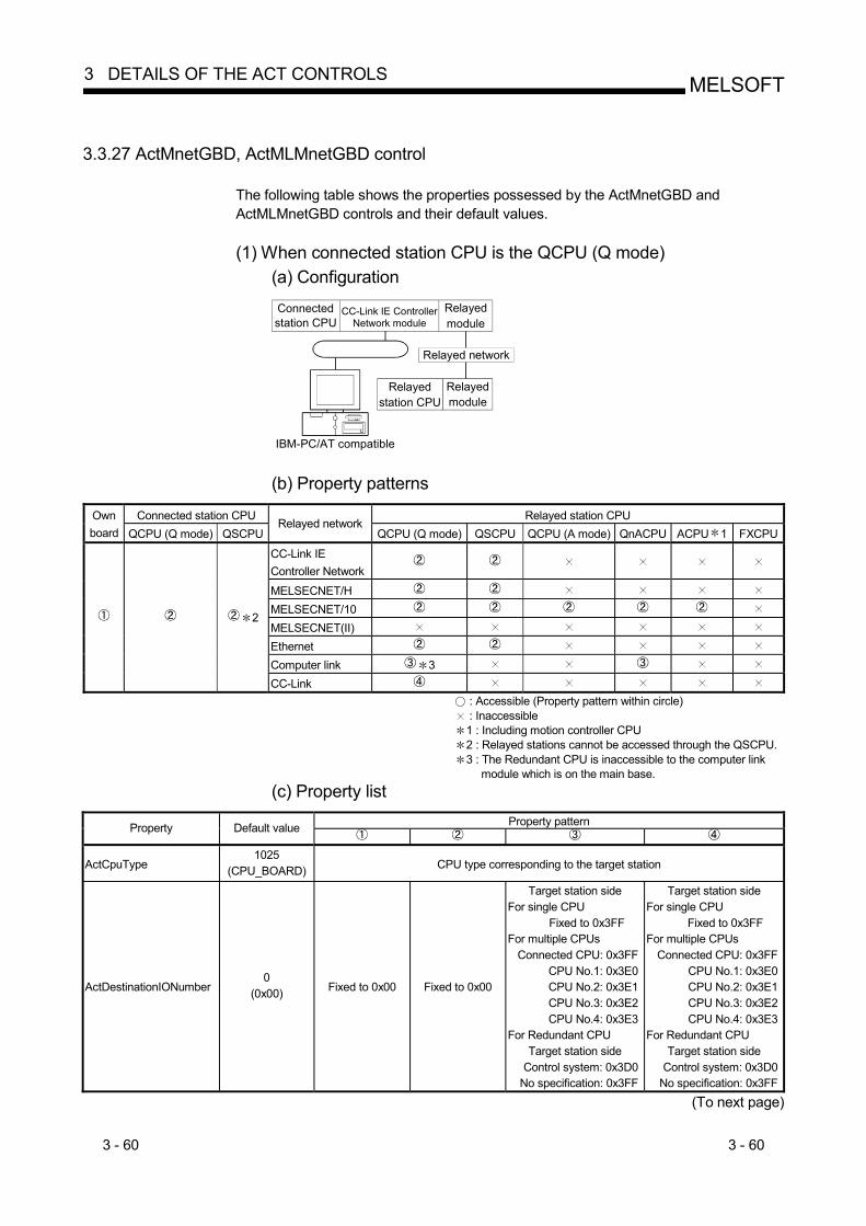
3 - 60 3 - 60
MELSOFT3 DETAILS OF THE ACT CONTROLS
3.3.27 ActMnetGBD, ActMLMnetGBD control
The following table shows the properties possessed by the ActMnetGBD and ActMLMnetGBD controls and their default values. (1) When connected station CPU is the QCPU (Q mode)
(a) Configuration
IBM-PC/AT compatible
Connected station CPU
CC-Link IE ControllerNetwork module
Relayedmodule
Relayed network
Relayed station CPU
Relayedmodule
(b) Property patterns
Connected station CPU Relayed station CPU Own
board QCPU (Q mode) QSCPURelayed network
QCPU (Q mode) QSCPU QCPU (A mode) QnACPU ACPU 1 FXCPU
CC-Link IE Controller Network
MELSECNET/H MELSECNET/10 MELSECNET(II) Ethernet Computer link 3
2
CC-Link : Accessible (Property pattern within circle) : Inaccessible 1 : Including motion controller CPU 2 : Relayed stations cannot be accessed through the QSCPU. 3 : The Redundant CPU is inaccessible to the computer link
module which is on the main base. (c) Property list
Property pattern Property Default value
ActCpuType 1025
(CPU_BOARD) CPU type corresponding to the target station
ActDestinationIONumber 0
(0x00) Fixed to 0x00 Fixed to 0x00
Target station side For single CPU
Fixed to 0x3FF For multiple CPUs
Connected CPU: 0x3FF CPU No.1: 0x3E0 CPU No.2: 0x3E1 CPU No.3: 0x3E2 CPU No.4: 0x3E3
For Redundant CPU Target station side
Control system: 0x3D0 No specification: 0x3FF
Target station side For single CPU
Fixed to 0x3FF For multiple CPUs
Connected CPU: 0x3FFCPU No.1: 0x3E0CPU No.2: 0x3E1CPU No.3: 0x3E2CPU No.4: 0x3E3
For Redundant CPU Target station side
Control system: 0x3D0No specification: 0x3FF
(To next page)

3 - 61 3 - 61
MELSOFT3 DETAILS OF THE ACT CONTROLS
Property pattern
Property Default value
ActDidPropertyBit 0
(0x00) Fixed to 0x01 Fixed to 0x01 Fixed to 0x00 Fixed to 0x00
ActDsidPropertyBit 0
(0x00) Fixed to 0x01 Fixed to 0x01 Fixed to 0x00 Fixed to 0x00
ActIONumber 4 0
(0x00) Fixed to 0x3FF
For single CPU Fixed to 0x3FF
For multiple CPUs Connected CPU: 0x3FF
CPU No.1: 0x3E0CPU No.2: 0x3E1CPU No.3: 0x3E2CPU No.4: 0x3E3
For Redundant CPU Target station side Control system: 0x3D0
No specification: 0x3FF
Relayed module I/O address on
connected station side
Relayed module I/Oaddress on
connected station side
ActMultiDropChannelNumber 5 0
(0x00) Fixed to 0x00 Fixed to 0x00 Multidrop channel
number Fixed to 0x00
ActNetworkNumber 0
(0x00) Fixed to 0x00 Module network number on
target station side
Module network number on
connected station side
Module network number on
connected station side
ActPortNumber 1
(PORT_1) CC-Link IE Controller Network board on IBM-PC/AT-compatible personal computer side,
whose board number is any of PORT1 to PORT4 (First to fourth)
ActStationNumber 255
(0xFF) Fixed to 0xFF Module station number on
target station side
Module station number on
connected station side
Module station number on
connected station side
ActThroughNetworkType 1
(0x01) Refer to the property [ActThroughNetworkType] in Section 3.2.
ActUnitNumber 0
(0x00) Fixed to 0x00 Fixed to 0x00 Module station
number on target station side
Module station number on target
station side 4: As the I/O address, specify the value found by dividing the actual first I/O number by 16. 5: Specify the following as the channel No. to be multidrop-linked.
0: Use default channel of module. 1: Channel 1 2: Channel 2

3 - 62 3 - 62
MELSOFT3 DETAILS OF THE ACT CONTROLS
3.3.28 ActCCBD, ActMLCCBD control
The following table indicates the properties possessed by the ActCCBD, ActMLCCBD control and their default values. (1) When connected station CPU is QCPU (Q mode)
(a) Configuration
IBM-PC/AT compatible
Connected station CPU CC-Link module
Relayedmodule
Relayed network
Relayed station CPU
Relayedmodule
(b) Property patterns Connected Station CPU Relayed Station CPU Own
Board QCPU (Q mode) Relayed Network
QCPU (Q mode) QSCPU QCPU (A mode) QnACPU ACPU 1 FXCPUCC-Link IE Controller Network
MELSECNET/H MELSECNET/10 MELSECNET(II) Ethernet Computer link
CC-Link : Accessible (Property pattern within circle) : Inaccessible 1 : Including motion controller CPU
(c) Property list Property Patterns Property Default Value
ActCpuType 1025
(CPU_BOARD) CPU type corresponding to target station
ActDestinationIONumber 0
(0x00) Fixed to 0x00
Target station side For single CPU
0x3FF fixedFor multiple CPUs
Connected CPU: 0x3FFNo. 1: 0x3E0No. 2: 0x3E1No. 3: 0x3E2No. 4: 0x3E3
For Redundant CPU Target station side
Control system: 0x3D0No specification: 0x3FF
Target station side For single CPU
0x3FF fixedFor multiple CPUs
Connected CPU: 0x3FFNo. 1: 0x3E0No. 2: 0x3E1No. 3: 0x3E2No. 4: 0x3E3
For redundant CPU Target station side
Control system: 0x3D0No specification: 0x3FF
ActIONumber 0
(0x00) Fixed to 0x00 Fixed to 0x3FF Fixed to 0x3FF
ActNetworkNumber 0
(0x00) Fixed to 0x00 Fixed to 0x00 Target station side module network number
ActPortNumber 1
(PORT_1) Board No. of IBM-PC/AT compatible side CC-Link board,
PORT 1 to PORT 4 (first to fourth boards)
ActStationNumber 255
(0xFF) Fixed to 0xFF Target station side CC-Link module station number
Target station side module station number
ActUnitNumber 0
(0x00) Fixed to 0x00 Fixed to 0x00 Connected station side module station number

3 - 63 3 - 63
MELSOFT3 DETAILS OF THE ACT CONTROLS
(2) When connected station CPU is QCPU (A mode)
(a) Configuration
IBM-PC/AT compatible
Connected station CPU CC-Link module
Relayedmodule
Relayed network
Relayed station CPU
Relayedmodule
(b) Property patterns
Connected Station CPU Relayed Station CPU Own
Board QCPU (A mode) Relayed Network
QCPU (Q mode) QSCPU QCPU (A mode) QnACPU ACPU 1 FXCPU
CC-Link IE Controller Network
MELSECNET/H MELSECNET/10 MELSECNET(II) Ethernet Computer link
CC-Link : Accessible (Property pattern within circle) : Inaccessible 1 : Including motion controller CPU
(c) Property list
Property Patterns Property Default Value
ActCpuType 1025
(CPU_BOARD) CPU type corresponding to target station
ActDestinationIONumber 0
(0x00) Fixed to 0x00
ActIONumber 0
(0x00) Fixed to 0x00
ActNetworkNumber 0
(0x00) Fixed to 0x00
ActPortNumber 1
(PORT_1) Board No. of IBM-PC/AT compatible side CC-Link board,
PORT 1 to PORT 4 (first to fourth boards)
ActStationNumber 255
(0xFF) Fixed to 0xFF Target station side CC-Link module
station number
ActUnitNumber 0
(0x00) Fixed to 0x00

3 - 64 3 - 64
MELSOFT3 DETAILS OF THE ACT CONTROLS
(3) When connected station CPU is QnACPU
(a) Configuration
IBM-PC/AT compatible
Connected station CPU CC-Link module
Relayedmodule
Relayed network
Relayed station CPU
Relayedmodule
(b) Property patterns
Connected Station CPU Relayed Station CPU Own
Board QnACPU Relayed Network
QCPU (Q mode) QSCPU QCPU (A mode) QnACPU ACPU 1 FXCPU
CC-Link IE Controller Network
MELSECNET/H MELSECNET/10 MELSECNET(II) Ethernet Computer link
CC-Link : Accessible (Property pattern within circle) : Inaccessible 1 : Including motion controller CPU
(c) Property list
Property Patterns Property Default Value
ActCpuType 1025
(CPU_BOARD) CPU type corresponding to target station
ActDestinationIONumber 0
(0x00) Fixed to 0x00
ActIONumber 0
(0x00) Fixed to 0x3FF
ActNetworkNumber 0
(0x00) Fixed to 0x00 Fixed to 0x00 Target station side module
network number
ActPortNumber 1
(PORT_1) Board No. of IBM-PC/AT compatible side CC-Link board,
PORT 1 to PORT 4 (first to fourth boards)
ActStationNumber 255
(0xFF) Fixed to 0xFF Target station side CC-Link
module station number Target station side module
station number
ActUnitNumber 0
(0x00) Fixed to 0x00 Fixed to 0x00 Target station side CC-Link
module station number
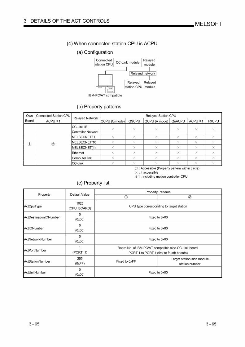
3 - 65 3 - 65
MELSOFT3 DETAILS OF THE ACT CONTROLS
(4) When connected station CPU is ACPU
(a) Configuration
IBM-PC/AT compatible
Connected station CPU CC-Link module
Relayedmodule
Relayed network
Relayed station CPU
Relayedmodule
(b) Property patterns
Connected Station CPU Relayed Station CPU Own
Board ACPU 1 Relayed Network
QCPU (Q mode) QSCPU QCPU (A mode) QnACPU ACPU 1 FXCPU
CC-Link IE Controller Network
MELSECNET/H MELSECNET/10 MELSECNET(II) Ethernet Computer link
CC-Link : Accessible (Property pattern within circle) : Inaccessible 1 : Including motion controller CPU
(c) Property list
Property Patterns Property Default Value
ActCpuType 1025
(CPU_BOARD) CPU type corresponding to target station
ActDestinationIONumber 0
(0x00) Fixed to 0x00
ActIONumber 0
(0x00) Fixed to 0x00
ActNetworkNumber 0
(0x00) Fixed to 0x00
ActPortNumber 1
(PORT_1) Board No. of IBM-PC/AT compatible side CC-Link board,
PORT 1 to PORT 4 (first to fourth boards)
ActStationNumber 255
(0xFF) Fixed to 0xFF Target station side module
station number
ActUnitNumber 0
(0x00) Fixed to 0x00

3 - 66 3 - 66
MELSOFT3 DETAILS OF THE ACT CONTROLS
3.3.29 ActAnUBD, ActMLAnUBD control
The following table indicates the properties possessed by the ActAnUBD, ActMLAnUBD control and their default values.
(1) Configuration (2) Property patterns
Connected Station CPU
Relayed Station CPU
Own Board
Relayed Network QCPU
(Q mode)QSCPU
QCPU (A mode)
QnA CPU
ACPU1
FXCPU
CC-Link IE Controller Network
MELSECNET/H MELSECNET/10 2 MELSECNET(II) 2 Ethernet Computer link
IBM-PC/AT compatible
Relayedmodule
Relayed network
Relayedstation CPU
Relayedmodule
Extension base unit
CC-Link
: Accessible (Property pattern within circle) : Inaccessible 1 : Including motion controller CPU 2 : Operates as the one equivalent to AnACPU.
(3) Property list
Property Patterns
Property Default Value
ActCpuType 271
(CPU_A2USHS1CPU) CPU type corresponding to target station
ActNetworkNumber 0
(0x00) Fixed to 0x00 Target station side module
network number Fixed to 0x00
ActStationNumber 255
(0xFF) Fixed to 0xFF Target station side module
station number Target station side module
station number

3 - 67 3 - 67
MELSOFT3 DETAILS OF THE ACT CONTROLS
3.3.30 ActLLT, ActMLLLT control
The following table indicates the properties possessed by the ActLLT, ActMLLLT control and their default values.
Property Pattern Property Default Value
Own station Other station
ActCpuType 34
(CPU_Q02CPU) CPU type corresponding to target station
ActNetworkNumber 0
(0x00) Fixed to 0x00
Target station side network number
ActStationNumber 255
(0xFF) Fixed to 0xFF
Target station side station number
ActTimeOut 10000 Any value specified by user in ms units
POINT
When any of the following settings has been included in the property settings, the access destination will be own station. • ActNetworkNumber: The number outside the range 1 to 255 has been set. • ActStationNumber: The number outside the range 0 to 64 has been set.
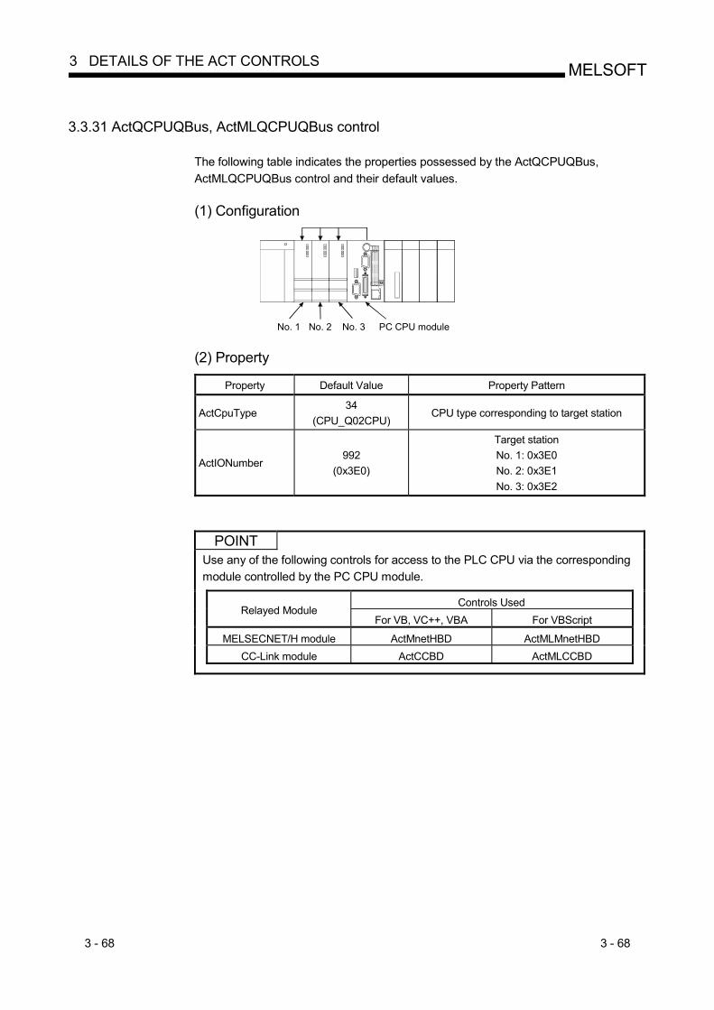
3 - 68 3 - 68
MELSOFT3 DETAILS OF THE ACT CONTROLS
3.3.31 ActQCPUQBus, ActMLQCPUQBus control
The following table indicates the properties possessed by the ActQCPUQBus, ActMLQCPUQBus control and their default values. (1) Configuration
No. 1 No. 2 No. 3 PC CPU module (2) Property
Property Default Value Property Pattern
ActCpuType 34
(CPU_Q02CPU) CPU type corresponding to target station
ActIONumber 992
(0x3E0)
Target station No. 1: 0x3E0 No. 2: 0x3E1 No. 3: 0x3E2
POINT Use any of the following controls for access to the PLC CPU via the corresponding module controlled by the PC CPU module.
Controls Used Relayed Module
For VB, VC++, VBA For VBScript
MELSECNET/H module ActMnetHBD ActMLMnetHBD
CC-Link module ActCCBD ActMLCCBD

3 - 69 3 - 69
MELSOFT3 DETAILS OF THE ACT CONTROLS
3.3.32 ActA6TEL control
The following table indicates the properties possessed by the ActA6TEL control and their default values. (1) Configuration
Connected station CPU
Relayedmodule
Relayed network
Relayed station CPU
Relayedmodule
IBM-PC/AT compatible
Modem
Subscriber line
Modem
(2) Property patterns Connected Station CPU Relayed Station CPU
ACPU 1 Relayed Network
QCPU (Q mode) QSCPU QCPU (A mode) QnACPU ACPU 1 FXCPU CC-Link IE Controller Network
MELSECNET/H MELSECNET/10 MELSECNET(II) Ethernet Computer link
CC-Link : Accessible (Property pattern within circle) : Inaccessible 1 : Including motion controller CPU
(3) Property list Property Patterns Property Default Value
ActATCommand Empty Any value specified by user ActATCommandPasswordCancelRetryTimes 3 Any value specified by user ActATCommandResponseWaitTime 1 Any value specified by user (unit s) ActConnectionCDWaitTime 90 Any value specified by user (unit s) ActConnectionModemReportWaitTime 5 Any value specified by user (unit s)
ActCpuType 262
(CPU_A1NCPU) CPU type corresponding to target station
ActDialNumber Empty Telephone number of any value specified by user ActDisconnectionCDWaitTime 5 Any value specified by user (unit s) ActDisconnectionDelayTime 3 Any value specified by user (unit s)
ActLineType 1
(LINETYPE_TONE) LINETYPE_PULSE, LINETYPE_TONE, LINETYPE_ISDN
ActNetworkNumber 0
(0x00) Fixed to 0x00 Target station side module network number Fixed to 0x00
ActOutsideLineNumber Empty Outside line access number of any value specified by user ActPassword Empty Password set to the Q6TEL and A6TEL ActPasswordCancelResponseWaitTime 5 Any value specified by user (unit s)
ActPortNumber 1
(PORT_1) IBM-PC/AT compatible side COM port number
ActStationNumber 255
(0xFF) Fixed to 0xFF Target station side module station number
Target station side module station number
ActTimeOut 10000 Any value specified by user in ms units ActTransmissionDelayTime 0 Any value specified by user (unit s)

3 - 70 3 - 70
MELSOFT3 DETAILS OF THE ACT CONTROLS
3.3.33 ActQ6TEL control
The following table indicates the properties possessed by the ActQ6TEL control and their default values. (1) Configuration
Connected station CPU
Relayedmodule
Relayed network
Relayed station CPU
Relayedmodule
IBM-PC/AT compatible
Modem
Subscriber line
Modem
(2) Property patterns
Connected Station CPU Relayed Station CPU QnACPU
Relayed Network QCPU (Q mode) QSCPU QCPU (A mode) QnACPU ACPU 1 FXCPU
CC-Link IE Controller Network
MELSECNET/H MELSECNET/10 MELSECNET(II) Ethernet Computer link
CC-Link : Accessible (Property pattern within circle) : Inaccessible 1 : Including motion controller CPU
(3) Property list Property Patterns
Property Default Value 3
ActATCommand Empty Any value specified by user
ActATCommandPasswordCancelRetryTimes 3 Any value specified by user
ActATCommandResponseWaitTime 1 Any value specified by user (unit s)
ActConnectionCDWaitTime 90 Any value specified by user (unit s)
ActConnectionModemReportWaitTime 5 Any value specified by user (unit s)
ActCpuType 17
(CPU_Q2ACPU) CPU type corresponding to target station
ActDialNumber Empty Telephone number of any value specified by user
ActDisconnectionCDWaitTime 5 Any value specified by user (unit s)
ActDisconnectionDelayTime 3 Any value specified by user (unit s)
ActIONumber 2 1023
(0x3FF) Fixed to 0x3FF
Fixed to 0x3FF
Fixed to 0x3FF
Connected station side module I/O address
ActLineType 1
(LINETYPE_TONE) LINETYPE_PULSE, LINETYPE_TONE, LINETYPE_ISDN
2 : As the I/O address, specify the value found by dividing the actual first I/O number by 16. 3 : Note the following points when making access via the Ethernet module (QE71).
• For ActNetworkNumber and ActStationNumber, specify the value set in the parameter setting of the target station side QE71. • Set the "Station No. IP information" in the parameter setting of the QE71. Also, when making setting, specify other than the
automatic response system (any of the IP address calculation system, table conversion system and combined system) as the "Station No. IP information system".
(To next page)
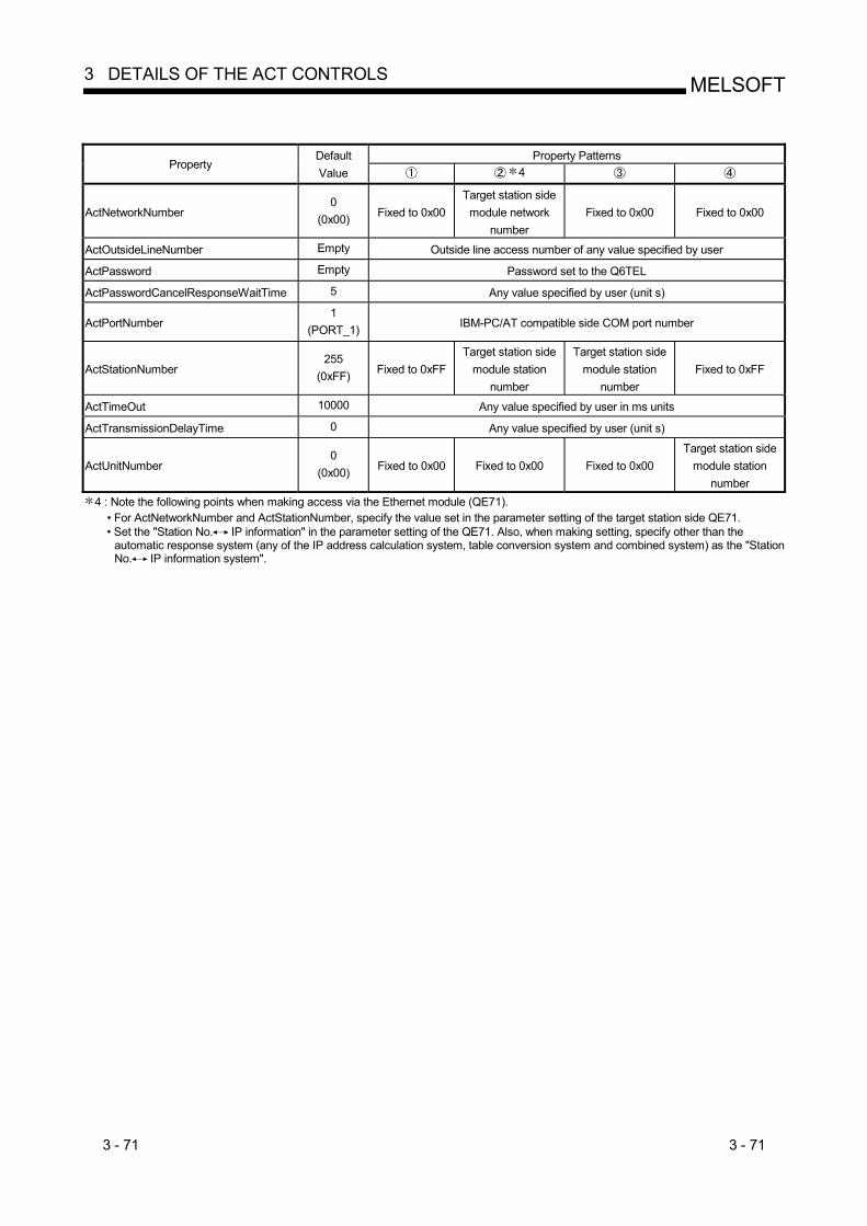
3 - 71 3 - 71
MELSOFT3 DETAILS OF THE ACT CONTROLS
Property Patterns
Property Default Value 4
ActNetworkNumber 0
(0x00) Fixed to 0x00 Target station side
module network number
Fixed to 0x00 Fixed to 0x00
ActOutsideLineNumber Empty Outside line access number of any value specified by user
ActPassword Empty Password set to the Q6TEL
ActPasswordCancelResponseWaitTime 5 Any value specified by user (unit s)
ActPortNumber 1
(PORT_1) IBM-PC/AT compatible side COM port number
ActStationNumber 255
(0xFF) Fixed to 0xFF Target station side
module station number
Target station side module station
number Fixed to 0xFF
ActTimeOut 10000 Any value specified by user in ms units
ActTransmissionDelayTime 0 Any value specified by user (unit s)
ActUnitNumber 0
(0x00) Fixed to 0x00 Fixed to 0x00 Fixed to 0x00 Target station side
module station number
4 : Note the following points when making access via the Ethernet module (QE71). • For ActNetworkNumber and ActStationNumber, specify the value set in the parameter setting of the target station side QE71. • Set the "Station No. IP information" in the parameter setting of the QE71. Also, when making setting, specify other than the
automatic response system (any of the IP address calculation system, table conversion system and combined system) as the "Station No. IP information system".
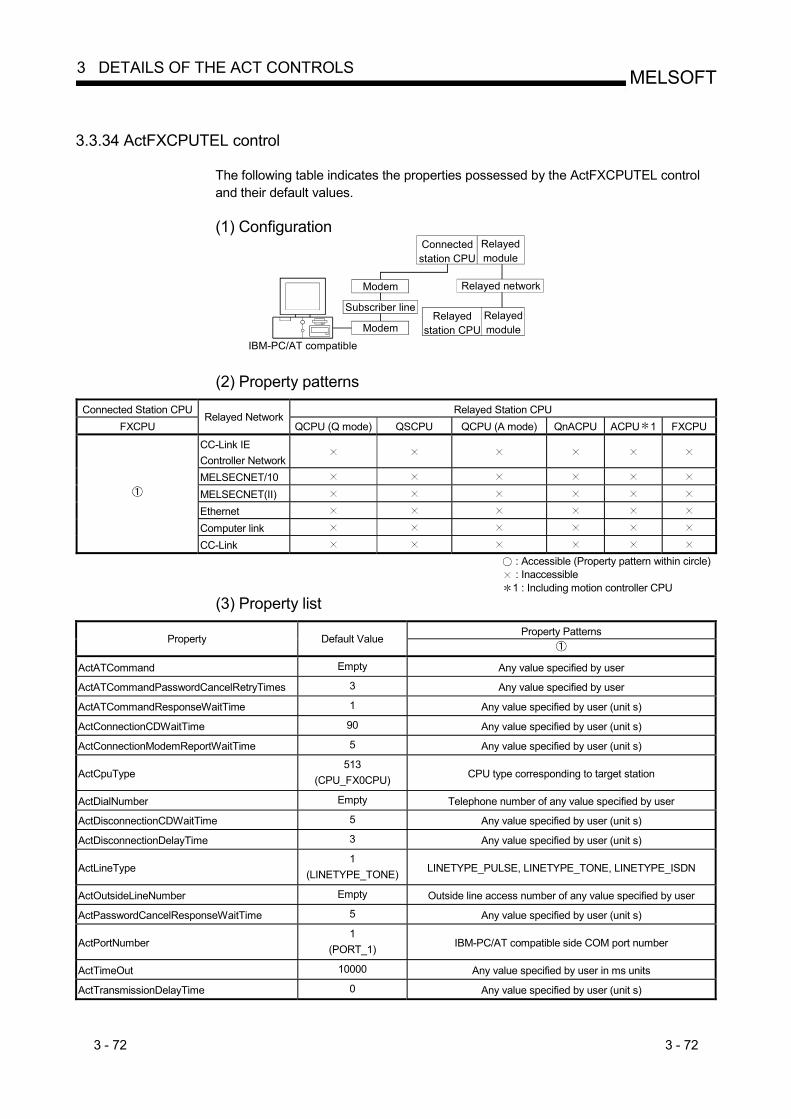
3 - 72 3 - 72
MELSOFT3 DETAILS OF THE ACT CONTROLS
3.3.34 ActFXCPUTEL control
The following table indicates the properties possessed by the ActFXCPUTEL control and their default values. (1) Configuration
Connected station CPU
Relayedmodule
Relayed network
Relayed station CPU
Relayedmodule
IBM-PC/AT compatible
Modem
Subscriber line
Modem
(2) Property patterns
Connected Station CPU Relayed Station CPU FXCPU
Relayed Network QCPU (Q mode) QSCPU QCPU (A mode) QnACPU ACPU 1 FXCPU
CC-Link IE Controller Network
MELSECNET/10 MELSECNET(II) Ethernet Computer link
CC-Link : Accessible (Property pattern within circle) : Inaccessible 1 : Including motion controller CPU
(3) Property list Property Patterns
Property Default Value
ActATCommand Empty Any value specified by user
ActATCommandPasswordCancelRetryTimes 3 Any value specified by user
ActATCommandResponseWaitTime 1 Any value specified by user (unit s)
ActConnectionCDWaitTime 90 Any value specified by user (unit s)
ActConnectionModemReportWaitTime 5 Any value specified by user (unit s)
ActCpuType 513
(CPU_FX0CPU) CPU type corresponding to target station
ActDialNumber Empty Telephone number of any value specified by user
ActDisconnectionCDWaitTime 5 Any value specified by user (unit s)
ActDisconnectionDelayTime 3 Any value specified by user (unit s)
ActLineType 1
(LINETYPE_TONE) LINETYPE_PULSE, LINETYPE_TONE, LINETYPE_ISDN
ActOutsideLineNumber Empty Outside line access number of any value specified by user
ActPasswordCancelResponseWaitTime 5 Any value specified by user (unit s)
ActPortNumber 1
(PORT_1) IBM-PC/AT compatible side COM port number
ActTimeOut 10000 Any value specified by user in ms units
ActTransmissionDelayTime 0 Any value specified by user (unit s)

3 - 73 3 - 73
MELSOFT3 DETAILS OF THE ACT CONTROLS
3.3.35 ActQJ71C24TEL control
The following table indicates the properties possessed by the ActQJ71C24TEL control and their default values. (1) When there is relayed module in addition to connected station side
Q series-compatible C24 (a) Configuration
Connected station CPU
Relayedmodule
Relayed network
Relayed station CPU
Relayedmodule
IBM-PC/AT compatible
Modem
Subscriber line
Modem
Q series-compatible C24
(b) Property patterns
Connected Station CPU Relayed Station CPU QCPU (Q mode)
Relayed Network QCPU (Q mode) QSCPU QCPU (A mode) QnACPU ACPU 1 FXCPU
CC-Link IE Controller Network
MELSECNET/H MELSECNET/10 MELSECNET(II) Ethernet Computer link 2
CC-Link : Accessible (Property pattern within circle) : Inaccessible 1 : Including motion controller CPU 2 : The Redundant CPU is inaccessible to
the computer link module which is on the main base.
(c) Property list Property Patterns
Property Default Value 3
ActATCommand Empty Any value specified by user
ActATCommandPasswordCancelRetryTimes 3 Any value specified by user
ActATCommandResponseWaitTime 1 Any value specified by user (unit s)
ActBaudRate 19200
(BAUDRATE_19200)
BAUDRATE_9600, BAUDRATE_19200, BAUDRATE_38400, BAUDRATE_5700, BAUDRATE_115200
(Match to the setting of Q series-compatible C24)
ActCallbackCancelWaitTime 90 Any value specified by user (unit s)
ActCallbackDelayTime 20 Any value specified by user (unit s)
ActCallbackNumber Empty Telephone number of any value specified by user
ActCallbackReceptionWaitingTimeOut 120 Any value specified by user (unit s)
ActConnectionCDWaitTime 90 Any value specified by user (unit s) 3 : Note the following points when making access via the Ethernet module (QE71).
• For ActNetworkNumber and ActStationNumber, specify the value set in the parameter setting of the target station side QE71. • Set the "Station No. IP information" in the parameter setting of the QE71. Also, when making setting, specify other than the
automatic response system (any of the IP address calculation system, table conversion system and combined system) as the "Station No. IP information system".
(To next page)

3 - 74 3 - 74
MELSOFT3 DETAILS OF THE ACT CONTROLS
Property Patterns
Property Default Value 5
ActConnectionModemReport WaitTime
5 Any value specified by user (unit s)
ActConnectUnitNumber 0
(0x00) Connected station side module station number
ActConnectWay 0
(TEL_AUTO_ CONNECT)
TEL_AUTO_CONNECT, TEL_AUTO_CALLBACK, TEL_AUTO_CALLBACK_NUMBER, TEL_CALLBACK, TEL_CALLBACK_NUMBER,
TEL_CALLBACK_REQUEST, TEL_CALLBACK_REQUEST_NUMBER, TEL_CALLBACK_WAIT (Depending on callback function setting)
ActCpuType 34
(CPU_Q02CPU) CPU type corresponding to target station
ActDestinationIONumber 0
(0x00) Fixed to 0x00 Fixed to 0x00
Target station side For single CPU
0x3FF fixed For multiple CPUs
Connected CPU: 0x3FF
No. 1: 0x3E0 No. 2: 0x3E1 No. 3: 0x3E2 No. 4: 0x3E3
For Redundant CPU Target station side Control system:
0x3D0 No specification:
0x3FF
Target station side For single CPU
0x3FF fixedFor multiple CPUs
Connected CPU: 0x3FF
No. 1: 0x3E0No. 2: 0x3E1No. 3: 0x3E2No. 4: 0x3E3
For Redundant CPUControl system:
0x3D0No specification:
0x3FF
ActDialNumber Empty Telephone number of any value specified by user
ActDidpropertyBit 1
(0x01) 0x01 0x01 0x00 0x00
ActDisconnectionCDWaitTime 5 Any value specified by user (unit s)
ActDisconnectionDelayTime 3 Any value specified by user (unit s)
ActDsidPropertyBit 1
(0x01) 0x01 0x01 0x00 0x00
ActIntelligentPreferenceBit 0
(0x00) Fixed to 0x00 Fixed to 0x00 Fixed to 0x00 Fixed to 0x00
ActIONumber 4 1023
(0x3FF)
Target station side For single CPU
0x3FF fixedFor multiple CPUs
Connected CPU: 0x3FF
No. 1: 0x3E0No. 2: 0x3E1No. 3: 0x3E2No. 4: 0x3E3
For Redundant CPUControl system:
0x3D0No specification:
0x3FF
Target station side For single CPU
0x3FF fixedFor multiple CPUs
Connected CPU: 0x3FF
No. 1: 0x3E0No. 2: 0x3E1No. 3: 0x3E2No. 4: 0x3E3
For Redundant CPUControl system:
0x3D0No specification:
0x3FF
Connected station side relayed module
I/O address
Connected station side relayed module
I/O address
4: As the I/O address, specify the value found by dividing the actual first I/O number by 16. 5: Note the following points when making access via the Ethernet module (QE71).
• For ActNetworkNumber and ActStationNumber, specify the value set in the parameter setting of the target station side QE71. • Set the "Station No. IP information" in the parameter setting of the QE71. Also, when making setting, specify other than the
automatic response system (any of the IP address calculation system, table conversion system and combined system) as the "Station No. IP information system".
(To next page)
3 - 75 3 - 75
MELSOFT3 DETAILS OF THE ACT CONTROLS
Property Patterns
Property Default Value 7
ActLineType 1
(LINETYPE_TONE) LINETYPE_PULSE, LINETYPE_TONE, LINETYPE_ISDN
ActMultiDropChannelNumber 6 0
(0x00) Fixed to 0x00 Fixed to 0x00 Multidrop channel
number Fixed to 0x00
ActNetworkNumber 0
(0x00) Fixed to 0x00 Target station side module network
number Fixed to 0x00 Fixed to 0x00
ActOutsideLineNumber Empty Outside line access number of any value specified by user
ActPassword Empty Password set to the Q series-compatible C24
ActPasswordCancelResponse WaitTime
5 Any value specified by user (unit s)
ActPortNumber 1
(PORT_1) IBM-PC/AT compatible side COM port number
ActStationNumber 255
(0xFF) Fixed to 0xFF Target station side
module station number
Fixed to 0xFF Fixed to 0xFF
ActThroughNetworkType 0
(0x00) Refer to the property [ActThroughNetworkType] in Section 3.2.
ActTimeOut 10000 Any value specified by user in ms units
ActTransmissionDelayTime 0 Any value specified by user (unit s)
ActUnitNumber 0
(0x00) Fixed to 0x00 Fixed to 0x00 Target station side
module station number
Target station side module station
number 6: Specify the following as the channel No. to be multidrop-linked.
0: Use default channel of module. 1: Channel 1 2: Channel 2
7: Note the following points when making access via the Ethernet module (QE71). • For ActNetworkNumber and ActStationNumber, specify the value set in the parameter setting of the target station side QE71. • Set the "Station No. IP information" in the parameter setting of the QE71. Also, when making setting, specify other than the
automatic response system (any of the IP address calculation system, table conversion system and combined system) as the "Station No. IP information system".

3 - 76 3 - 76
MELSOFT3 DETAILS OF THE ACT CONTROLS
(2) When connected station side Q series-compatible C24 is used for
multidrop link with relayed module (a) Configuration
Connected station CPU
Relayed station CPU
Relayedmodule
IBM-PC/AT compatible
Modem
Subscriber line
Modem
Q series-compatible C24
Multidrop link
(b) Property patterns
Connected Station CPU Relayed Station CPU QCPU (Q mode)
Relayed Network QCPU (Q mode) QSCPU QCPU (A mode) QnACPU ACPU 1 FXCPU
Independent mode 2 Computer link : Accessible (Property pattern within circle) : Inaccessible 1 : Including motion controller CPU 2 : The independent mode indicates that the parameters
have been set as indicated below. CH1 side: Operation setting for transmission setting =
independent (0), communication protocol setting = 0
CH2 side: Operation setting for transmission setting = independent (0)
(c) Property list Property Patterns
Property Default Value
ActATCommand Empty Any value specified by user
ActATCommandPasswordCancelRetryTimes 3 Any value specified by user
ActATCommandResponseWaitTime 1 Any value specified by user (unit s)
ActBaudRate 19200
(BAUDRATE_19200)
BAUDRATE_9600, BAUDRATE_19200, BAUDRATE_38400, BAUDRATE_57600, BAUDRATE_115200
(Match to the setting of Q series-compatible C24) ActCallbackCancelWaitTime 90 Any value specified by user (unit s)
ActCallbackDelayTime 20 Any value specified by user (unit s)
ActCallbackNumber Empty Telephone number of any value specified by user
ActCallbackReceptionWaitingTimeOut 120 Any value specified by user (unit s)
ActConnectionCDWaitTime 90 Any value specified by user (unit s)
ActConnectionModemReportWaitTime 5 Any value specified by user (unit s)
ActConnectUnitNumber 0
(0x00) Connected station side module station number
Connected station side module station number
ActConnectWay 0
(TEL_AUTO_CONNECT)
TEL_AUTO_CONNECT, TEL_AUTO_CALLBACK, TEL_CALLBACK, TEL_CALLBACK_NUMBER,
TEL_CALLBACK_REQUEST, TEL_CALLBACK_REQUEST_NUMBER,
TEL_CALLBACK_WAIT (Depending on callback function setting)
ActCpuType 34
(CPU_Q02CPU) CPU type corresponding to target station
(To next page)

3 - 77 3 - 77
MELSOFT3 DETAILS OF THE ACT CONTROLS
Property Patterns
Property Default Value
ActDestinationIONumber 0
(0x00) Fixed to 0x00
Target station side For single CPU
0x3FF fixedFor multiple CPUs
Connected CPU: 0x3FFNo. 1: 0x3E0No. 2: 0x3E1No. 3: 0x3E2No. 4: 0x3E3
ActDialNumber Empty Telephone number of any value specified by user
ActDidpropertyBit 1
(0x01) 0x01 0x00
ActDisconnectionCDWaitTime 5 Any value specified by user (unit s)
ActDisconnectionDelayTime 3 Any value specified by user (unit s)
ActDsidPropertyBit 1
(0x01) 0x01 0x00
ActIntelligentPreferenceBit 0
(0x00) Fixed to 0x00 Fixed to 0x00
ActIONumber 3 1023
(0x3FF)
Target station side For single CPU
0x3FF fixedFor multiple CPUs
Connected CPU: 0x3FFNo. 1: 0x3E0No. 2: 0x3E1No. 3: 0x3E2No. 4: 0x3E3
Connected station side relayed module I/O address
ActLineType 1
(LINETYPE_TONE) LINETYPE_PULSE, LINETYPE_TONE, LINETYPE_ISDN
ActMultiDropChannelNumber 4 0
(0x00) Fixed to 0x00 Multidrop channel number
ActNetworkNumber 0
(0x00) Fixed to 0x00 Fixed to 0x00
ActOutsideLineNumber Empty Outside line access number of any value specified by user
ActPassword Empty Password set to the Q series-compatible C24
ActPasswordCancelResponseWaitTime 5 Any value specified by user (unit s)
ActPortNumber 1
(PORT_1) IBM-PC/AT compatible side COM port number
ActStationNumber 255
(0xFF) Fixed to 0xFF Fixed to 0xFF
ActThroughNetworkType 0
(0x00) Refer to the property [ActThroughNetworkType] in Section 3.2.
ActTimeOut 10000 Any value specified by user in ms units
ActTransmissionDelayTime 0 Any value specified by user (unit s)
ActUnitNumber 0
(0x00) Fixed to 0x00 Target station side module
station number 3 : As the I/O address, specify the value found by dividing the actual first I/O number by 16. 4 : Specify the following as the channel No. to be multidrop-linked.
0: Use default channel of module. 1: Channel 1 2: Channel 2

3 - 78 3 - 78
MELSOFT3 DETAILS OF THE ACT CONTROLS
3.3.36 ActAJ71QC24TEL control
The following table indicates the properties possessed by the ActAJ71QC24TEL control and their default values. (1) When there is relayed module in addition to connected station side
QC24 (a) Configuration
Connected station CPU
Relayedmodule
Relayed network
Relayed station CPU
Relayedmodule
IBM-PC/AT compatible
Modem
Subscriber line
Modem
QC24N
(b) Property patterns Connected Station CPU Relayed Station CPU
QnACPU Relayed Network
QCPU (Q mode) QSCPU QCPU (A mode) QnACPU ACPU 1 FXCPU
CC-Link IE Controller Network
MELSECNET/H MELSECNET/10 MELSECNET(II) Ethernet Computer link
CC-Link : Accessible (Property pattern within circle) : Inaccessible 1 : Including motion controller CPU
(c) Property list Property Patterns
Property Default Value 2
ActATCommand Empty Any value specified by user
ActATCommandPasswordCancelRetryTimes 3 Any value specified by user
ActATCommandResponseWaitTime 1 Any value specified by user (unit s)
ActBaudRate 19200
(BAUDRATE_19200) Match to the setting of QC24N.
ActConnectionCDWaitTime 90 Any value specified by user (unit s)
ActConnectionModemReportWaitTime 5 Any value specified by user (unit s)
ActConnectUnitNumber 0
(0x00) Connected station side module station number
ActCpuType 17
(CPU_Q2ACPU) CPU type corresponding to target station
ActDialNumber Empty Telephone number of any value specified by user
2 : Note the following points when making access via the Ethernet module (QE71). • For ActNetworkNumber and ActStationNumber, specify the value set in the parameter setting of the target station side QE71. • Set the "Station No. IP information" in the parameter setting of the QE71. Also, when making setting, specify other than the
automatic response system (any of the IP address calculation system, table conversion system and combined system) as the "Station No. IP information system".
(To next page)

3 - 79 3 - 79
MELSOFT3 DETAILS OF THE ACT CONTROLS
Property Patterns
Property Default Value 4
ActDisconnectionCDWaitTime 5 Any value specified by user (unit s) ActDisconnectionDelayTime 3 Any value specified by user (unit s)
ActIONumber 3 1023
(0x3FF) Fixed to 0x3FF
Fixed to 0x3FF Fixed to 0x3FF Connected station
side relayed module I/O address
ActLineType 1
(LINETYPE_TONE)LINETYPE_PULSE, LINETYPE_TONE, LINETYPE_ISDN
ActNetworkNumber 0
(0x00) Fixed to 0x00
Target station side module
network numberFixed to 0x00 Fixed to 0x00
ActOutsideLineNumber Empty Outside line access number of any value specified by user ActPasswordCancelResponseWaitTime 5 Any value specified by user (unit s)
ActPortNumber 1
(PORT_1) IBM-PC/AT compatible side COM port number
ActStationNumber 255
(0xFF) Fixed to 0xFF
Target station side module
station number
Target station side module
station number Fixed to 0xFF
ActTimeOut 10000 Any value specified by user in ms units ActTransmissionDelayTime 0 Any value specified by user (unit s)
ActUnitNumber 0
(0x00) Fixed to 0x00 Fixed to 0x00 Fixed to 0x00
Target station side module station
number 3 : As the I/O address, specify the value found by dividing the actual first I/O number by 16. 4 : Note the following points when making access via the Ethernet module (QE71).
• For ActNetworkNumber and ActStationNumber, specify the value set in the parameter setting of the target station side QE71. • Set the "Station No. IP information" in the parameter setting of the QE71. Also, when making setting, specify other than the
automatic response system (any of the IP address calculation system, table conversion system and combined system) as the "Station No. IP information system".

3 - 80 3 - 80
MELSOFT3 DETAILS OF THE ACT CONTROLS
(2) When connected station side QC24 is used for multidrop link with
relayed module (a) Configuration
Connected station CPU
Relayed station CPU
Relayedmodule
IBM-PC/AT compatible
Modem
Subscriber line
Modem
QC24N
Multidrop link
(b) Property patterns
Connected Station CPU Relayed Station CPU QCPU (Q mode)
Relayed Network QCPU (Q mode) QSCPU QCPU (A mode) QnACPU ACPU 1 FXCPU
Independent mode 2 Computer link : Accessible (Property pattern within circle) : Inaccessible 1 : Including motion controller CPU 2 : The independent mode indicates that the module switch
have been set as indicated below. CH1 side: Mode setting switch = 5, SW01 of operation setting switch = OFF
(c) Property list Property Patterns
Property Default Value
ActATCommand Empty Any value specified by user
ActATCommandPasswordCancelRetryTimes 3 Any value specified by user
ActATCommandResponseWaitTime 1 Any value specified by user (unit s)
ActBaudRate 19200
(BAUDRATE_19200) Match to the setting of QC24N.
ActConnectionCDWaitTime 90 Any value specified by user (unit s)
ActConnectionModemReportWaitTime 5 Any value specified by user (unit s)
ActConnectUnitNumber 0
(0x00) Connected station side module station number
Connected station side module station number
ActCpuType 17
(CPU_Q2ACPU) CPU type corresponding to target station
ActDialNumber Empty Telephone number of any value specified by user
ActDisconnectionCDWaitTime 5 Any value specified by user (unit s)
ActDisconnectionDelayTime 3 Any value specified by user (unit s)
ActIONumber 3 1023
(0x3FF) Fixed to 0x3FF Connected station side relayed
module I/O address
ActLineType 1
(LINETYPE_TONE) LINETYPE_PULSE, LINETYPE_TONE, LINETYPE_ISDN
ActNetworkNumber 0
(0x00) Fixed to 0x00 Fixed to 0x00
ActOutsideLineNumber Empty Outside line access number of any value specified by user 3 : As the I/O address, specify the value found by dividing the actual first I/O number by 16.
(To next page)

3 - 81 3 - 81
MELSOFT3 DETAILS OF THE ACT CONTROLS
Property Patterns
Property Default Value
ActPasswordCancelResponseWaitTime 5 Any value specified by user (unit s)
ActPortNumber 1
(PORT_1) IBM-PC/AT compatible side COM port number
ActStationNumber 255
(0xFF) Fixed to 0xFF Fixed to 0xFF
ActTimeOut 10000 Any value specified by user in ms units
ActTransmissionDelayTime 0 Any value specified by user (unit s)
ActUnitNumber 0
(0x00) Fixed to 0xFF Target station side module station
number

3 - 82 3 - 82
MELSOFT3 DETAILS OF THE ACT CONTROLS
3.3.37 ActGOT, ActMLGOT control
The following table indicates the properties possessed by the ActGOT, ActMLGOT control and their default values. (1) Configuration
IBM-PC/AT compatible
GOT
(2) Property patterns
Property patterns
Property Default value
ActHostAddress 1.1.1.1 Host name or IP address of connected GOT
ActPortNumber 5011 IBM-PC/AT compatible side COM port number
ActTimeOut 10000 Any value specified by user in ms units

3 - 83 3 - 83
MELSOFT3 DETAILS OF THE ACT CONTROLS
MEMO

4 - 1 4 - 1
MELSOFT4 FUNCTIONS
4 FUNCTIONS
This chapter provides the programming instructions and function details (dispatch interface 1, custom interface 2).
1 : The dispatch interface is a method in which the ActiveX controls are pasted onto
Visual Basic R , Visual C++ R or VBA (Excel, Access) to use the ActiveX controls. You need not program interface acquirement and object generation. (You can also create a program that will create an object without pasting the ActiveX control to a form.) The dispatch interface is easier in programming than the customer interface. For MX Component, it is recommended to use the dispatch interface to create user applications.
2 : The custom interface gets the interface using the interface getting function when
using the ActiveX controls. It also uses the object generation function when generating objects. Though the custom interface is more complicated in program than the dispatch interface, it can perform fine control of object generation/elimination.
POINT
For programming, refer to "Section 4.1 Programming Instructions". 4.1 Programming Instructions
This section gives the instructions for programming.
(1) Instructions for multithread programming When performing multithread programming, follow the rules of COM and ActiveX controls. For details, refer to the rules and reference books of COM and ActiveX controls.
POINT
(1) The ActiveX controls used on MX Component are those of the STA model. (2) When passed to another apartment, the interface pointer must be marshaled.
Provide synchronization using the CoMarshalInterThreadInterfaceInStream or CoGetInterfaceAndReleaseStream COM function.
(2) Instructions for use of Visual Basic R 6.0
Only the dispatch interface is usable.
4

4 - 2 4 - 2
MELSOFT4 FUNCTIONS
(3) Instructions for use of Visual C++ R 6.0 (dispatch interface, custom
interface) (a) Both the dispatch interface and custom interface are usable.
(b) BSTR type
In the functions which acquire the methods and properties using the BSTR pointer type, memory must be secured inside the ActiveX controls and released in user programs. (This is based on the rules of COM and ActiveX controls.) (Example)
BSTR szCpuName; LONG lCpuCode; Obj.GetCpuType(&szCpuName, &lCpuCode ); MessgBox( “CpuName = %s, CpuCode = %d”, szCpuName, lCpuCode ); SysFreeString( szCpuName );
(4) Instructions for use of Visual C++ R 6.0 (custom interface) (a) HRESULT type
Use the SUCCEEDED or FAILED macro to check whether the HRESULT type, i.e. returned value of COM, resulted in normal or abnormal termination. (Example) HRESULT hResult; LONG lRet; hResult = Obj.Open( &lRet ); if( SUCCEEDE( hResult ) ) {
if( lRet = SUCCESS ) {
} else { MessgeBox( “Communication Error = %x”, lRet ); }
} else { MessgeBox( “COM ERROR Occurd” );
}
4

4 - 3 4 - 3
MELSOFT4 FUNCTIONS
(5) About Open (opening the communication line)
Since the Open function performs processing, e.g. establishes a communication path or gets the PLC internal information, the processing time may become long. An efficient program must be created to enhance the speed performance of the user application. The following flowcharts provide procedures for creating efficient and inefficient user applications.
Do you end the userapplication?
Start
Open the communication line. (Open)
Using the function(e.g. GetDevice),make access to the PLC CPU or module.
Close the communication line. (Close)
End
No
Yes
<Efficient User Application>
Do you end the userapplication?
Start
Open the communication line. (Open)
Using the function(e.g. GetDevice),make access to the PLC CPU or module.
Close the communication line. (Close)
End
No
Yes
<Inefficient User Application>
(6) Precautions for use of QSCPU The following function cannot be uded for the QSCPU. The error code "0x010a42a0" (The CPU access password is mismatched.) may be returned if they are used.
Function Name Function WriteDeviceBlock Device batch-write WriteDeviceRandom Device random-write SetDevice Device data setting WriteBuffer Buffer memory write SetClockData Clock data write SetCpuStatus Remote control WriteDeviceBlock2 Device batch-write WriteDeviceRandom2 Device random-write SetDevice2 Device data setting

4 - 4 4 - 4
MELSOFT4 FUNCTIONS
(7) Differences between LONG type functions and SHORT type/INT
type functions As functions for performing "device batch-read", "device batch-write", "device random-read", "device random-write", "device data setting" and "device data acquisition", MX Component has two different functions: LONG type functions and SHORT type/INT type functions. The following describes the differences between the LONG type functions and SHORT type/INT type functions.
(a) LONG type functions (Reference sections: Section 4.2.3 to Section 4.2.8)
When writing/reading a negative device value, by using the LONG type function the data must be converted into the SHORT type/INT type data within the user application. Write/read negative device values using the SHORT type/INT type functions indicated in (b).
Target functions : ReadDeviceBlock, WriteDeviceBlock, ReadDeviceRandom,
WriteDeviceRandom, SetDevice, GetDevice
D0 data is read usingReadDeviceBlock.
D0 = -1 (0xFFFF)
lplData = 65535 (0x0000FFFF)
Stored as LONG type (4-byte)data within user application.
Conversion intoSHORT type/INTtype
lpsData = (SHORT)lplData;lpsData = -1 (0xFFFF)
Data must be converted intoSHORT type/INT type (2-byte)data within user application.
Conversion operation
<Example> When reading device data that include negative value by using ReadDeviceBlock

4 - 5 4 - 5
MELSOFT4 FUNCTIONS
(b) SHORT type/INT type functions (Reference sections: Section 4.2.18 to
Section 4.2.23) When reading/writing a negative device value by using the SHORT type/INT type function, it is not required to convert the device value in advance. When handling a double word device or like, use any of the LONG type functions indicated in (a).
Target functions : ReadDeviceBlock2, WriteDeviceBlock2,
ReadDeviceRandom2, WriteDeviceRandom2, SetDevice2, GetDevice2
D0 data is read usingReadDeviceBlock2.
D0 = -1 (0xFFFF)
lpsData = -1 (0xFFFF)
Stored as SHORT type/INTtype (2-byte) data within userapplication.
<Example> When using ReadDeviceBlock2 to read device data of negative value

4 - 6 4 - 6
MELSOFT4 FUNCTIONS
4.2 Details of the Functions (Dispatch Interface)
This section explains the details of the functions. The details of the functions in this section assume that the dispatch interface is used. For the custom interface, refer to "Section 4.3 Details of the Functions (Custom Interface)".
4.2.1 Open (Communication line opening)
(1) Applicable ACT controls This function is available for all ACT controls but the ActSupoort and ActMLSupport controls.
(2) Feature
Opens the communication line.
(3) Format Visual Basic R 6.0, Visual C++ R 6.0, Visual C++ R .NET(MFC), VBA : lRet = object.Open()
Long lRet Returned value Output VBScript : varRet = object.Open()
VARIANT varRet Returned value (LONG type) Output Visual Basic R .NET : IRet = object.Open()
Integer IRet Returned value Output Visual C++ R .NET : iRet = object.Open()
int iRet Returned value Output
(4) Explanation The line is connected on the basis of the value set to the property for Open function.
(5) Returned value
Normal termination : 0 is returned. Abnormal termination : A value other than 0 is returned.
(Refer to Chapter 6 ERROR CODES.)
POINT (1) When modem communication is used, Open cannot be executed after
execution of Connect. (2) If the property for Open function is changed after completion of Open, the other
end of communication is not changed. To change the communication settings, close the communication line once, then set the other end of communication, and open the communication line again.
(3) When any ACT control other than the ActEasyIF or ActMLEasyIF control is used at the time of Open, Open may terminate normally if the CPU type entered into the ActCpuType property differs from the CPU to communicate with. In such a case, the connection range, usable method and device range may be narrowed, for example. When executing Open, set the correct CPU type to the ActCpuType property.

4 - 7 4 - 7
MELSOFT4 FUNCTIONS
4.2.2 Close (Communication line closing)
(1) Applicable ACT controls
This function is available for all ACT controls but the ActSupoort and ActMLSupport controls.
(2) Feature
Closes the communication line.
(3) Format Visual Basic R 6.0, Visual C++ R 6.0, Visual C++ R .NET(MFC), VBA : lRet = object.Close ()
Long lRet Returned value Output VBScript : varRet = object.Close()
VARIANT varRet Returned value (LONG type) Output Visual Basic R .NET : IRet = object.Close()
Integer IRet Returned value Output Visual C++ R .NET : iRet = object.Close()
int iRet Returned value Output
(4) Explanation The line connected using the Open function is closed.
(5) Returned value
Normal termination : 0 is returned. Abnormal termination : A value other than 0 is returned.
(Refer to Chapter 6 ERROR CODES.)

4 - 8 4 - 8
MELSOFT4 FUNCTIONS
4.2.3 ReadDeviceBlock (Device batch-read)
(1) Applicable ACT controls This function is available for all ACT controls but the ActSupoort and ActMLSupport controls.
(2) Feature
Batch-reads data from devices. (3) Format
Visual Basic R 6.0, VBA : lRet = object.ReadDeviceBlock(szDevice, lSize, lData(0))
Long lRet Returned value Output String szDevice Device name Input Long lSize Number of read points Input Long lData(n) Read device values Output
Visual C++ R 6.0, Visual C++ R .NET(MFC) : lRet = object.ReadDeviceBlock
(szDevice, lSize, lplData) Long lRet Returned value Output CString szDevice Device name Input Long lSize Number of read points Input Long lplData Read device values Output
VBScript : varRet = object.ReadDeviceBlock(varDevice, varSize, lpvarData)
VARIANT varRet Returned value (LONG type) Output VARIANT varDevice Device name(character string type) Input VARIANT varSize Number of read points(LONG type) Input VARIANT lpvarData Read device values(LONG array type) Output
Visual Basic R .NET : IRet = object.ReadDeviceBlock(szDevice, iSize, iData(0))
Integer IRet Returned value Output String szDevice Device name Input Integer iSize Number of read points Input Integer iData(n) Read device values Output
Visual C++ R .NET : iRet = object.ReadDeviceBlock( szDevice, iSize, iplData)
int iRet Returned value Output String szDevice Device name Input int iSize Number of read points Input int iplData Read device values Output
(4) Explanation
(a) The device values for lSize(varSize) are batch-read from the devices, beginning with the device specified in szDevice(varDevice).
(b) The read device values are stored in lData (lplData or lpvarData). (c) Reserve an array of lSize (varSize) or more for lData (lplData or lpvarData).

4 - 9 4 - 9
MELSOFT4 FUNCTIONS
(5) Device specifying methods
Specify the devices in the following methods. <When bit device is specified> <When word device is specified> (Example) Data are read from 3 points
(3 words) on a 16 point basis, starting from M0.
(Example) 3 points from D0
2 Upper Bytes 2 Lower Bytes 2 Upper Bytes 2 Lower Bytes 1 M0 to M15 2 1 D0 1 M16 to M31 2 1 D1 1 M32 to M47 2 1 D2
<When CN200 and later of FXCPU are specified>
<When FD device is specified (4-word device)>
(Example) 6 points from CN200 3: (Example) 6 points from FD0 2 Upper Bytes 2 Lower Bytes 2 Upper Bytes 2 Lower Bytes
1 L of CN200 1 LL of FD0 1 H of CN200 1 LH of FD0 1 L of CN201 1 HL of FD0 1 H of CN201 1 HH of FD0 1 L of CN202 1 LL of FD1 1 H of CN202 1 LH of FD1
<8-bit devices assigned to gateway devices>
(Example) When 8-bit devices (E0000 to E0007 of SHARP PLC) have been assigned to 4 points, starting from EG0 (EG0 - EG3).
2 Upper Bytes 2 Lower Bytes EG0 1
(E0001) (E0000) EG1
1 (E0003) (E0002)
EG2 1
(E0005) (E0004) EG3
1 (E0007) (E0006)
1: Not used. (0 is stored.) 2: Lower bits are stored in device number order. 3: For CN200 or later of FXCPU, 2 words are read from 2 points. Read from 1 point will result in an error.
(6) Returned value
Normal termination : 0 is returned. Abnormal termination : Any value other than 0 is returned.
(Refer to Chapter 6 ERROR CODES.) POINT
(1) The maximum number of read points that may be specified in lSize(varSize) should satisfy the following range. Read starting device number + number of read points last device number
(2) When the bit device is specified, a multiple of 16 may be specified as the device number.
(3) For lData (lplData or lpvarData), prepare a memory area having the number of points specified in lSize (varSize). If there is no memory area, a critical phenomenon such as an application error may occur.
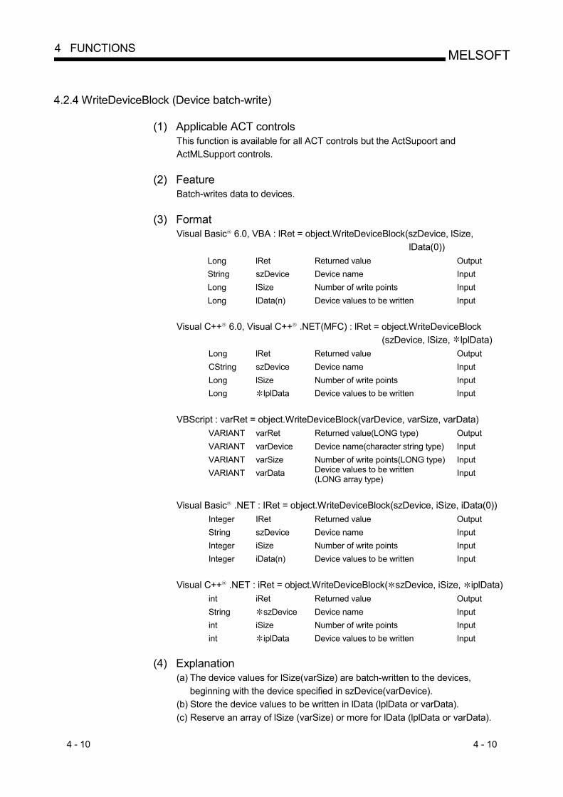
4 - 10 4 - 10
MELSOFT4 FUNCTIONS
4.2.4 WriteDeviceBlock (Device batch-write)
(1) Applicable ACT controls This function is available for all ACT controls but the ActSupoort and ActMLSupport controls.
(2) Feature
Batch-writes data to devices. (3) Format
Visual Basic R 6.0, VBA : lRet = object.WriteDeviceBlock(szDevice, lSize, lData(0))
Long lRet Returned value Output String szDevice Device name Input Long lSize Number of write points Input Long lData(n) Device values to be written Input
Visual C++ R 6.0, Visual C++ R .NET(MFC) : lRet = object.WriteDeviceBlock
(szDevice, lSize, lplData) Long lRet Returned value Output CString szDevice Device name Input Long lSize Number of write points Input Long lplData Device values to be written Input
VBScript : varRet = object.WriteDeviceBlock(varDevice, varSize, varData)
VARIANT varRet Returned value(LONG type) Output VARIANT varDevice Device name(character string type) Input VARIANT varSize Number of write points(LONG type) Input VARIANT varData Device values to be written
(LONG array type) Input
Visual Basic R .NET : IRet = object.WriteDeviceBlock(szDevice, iSize, iData(0))
Integer IRet Returned value Output String szDevice Device name Input Integer iSize Number of write points Input Integer iData(n) Device values to be written Input
Visual C++ R .NET : iRet = object.WriteDeviceBlock( szDevice, iSize, iplData)
int iRet Returned value Output String szDevice Device name Input int iSize Number of write points Input int iplData Device values to be written Input
(4) Explanation
(a) The device values for lSize(varSize) are batch-written to the devices, beginning with the device specified in szDevice(varDevice).
(b) Store the device values to be written in lData (lplData or varData). (c) Reserve an array of lSize (varSize) or more for lData (lplData or varData).

4 - 11 4 - 11
MELSOFT4 FUNCTIONS
(5) Device specifying methods
Specify the devices in the following methods. <When bit device is specified> <When word device is specified> (Example) Data are written to 3 points (3 words)
on a 16 point basis, starting from M0. (Example) 3 points from D0
2 Upper Bytes 2 Lower Bytes 2 Upper Bytes 2 Lower Bytes 1 M0 to M15 2 1 D0 1 M16 to M31 2 1 D1 1 M32 to M47 2 1 D2
<When CN200 and later of FXCPU are specified>
<When FD device is specified (4-word device)>
(Example) 6 points from CN200 3: (Example) 6 points from FD0 2 Upper Bytes 2 Lower Bytes 2 Upper Bytes 2 Lower Bytes
1 L of CN200 1 LL of FD0 1 H of CN200 1 LH of FD0 1 L of CN201 1 HL of FD0 1 H of CN201 1 HH of FD0 1 L of CN202 1 LL of FD1 1 H of CN202 1 LH of FD1
<8-bit devices assigned to gateway devices>
(Example) When 8-bit devices (E0000 to E0007 of SHARP PLC) have been assigned to 4 points, starting from EG0 (EG0 - EG3).
2 Upper Bytes 2 Lower Bytes EG0 1
(E0001) (E0000) EG1
1 (E0003) (E0002)
EG2 1
(E0005) (E0004) EG3
1 (E0007) (E0006)
1: Not used. (0 is stored.) 2: Lower bits are stored in device number order. 3: For CN200 or later of FXCPU, 2 words are written from 2 points. Write from 1 point will result in an error.
(6) Returned value
Normal termination : 0 is returned. Abnormal termination : Any value other than 0 is returned.
(Refer to Chapter 6 ERROR CODES.)
POINT (1) The maximum number of write points that may be specified in lSize(varSize)
should satisfy the following range. Write starting device number + number of write points last device number
(2) When the bit device is specified, a multiple of 16 may be specified as the device number.
(3) For lData (lplData or varData), prepare a memory area having the number of points specified in lSize (varSize). If there is no memory area, a critical phenomenon such as an application error may occur.

4 - 12 4 - 12
MELSOFT4 FUNCTIONS
4.2.5 ReadDeviceRandom (Device random-read)
(1) Applicable ACT controls This function is available for all ACT controls but the ActSupoort and ActMLSupport controls.
(2) Feature
Reads data randomly from devices.
(3) Format Visual Basic R 6.0, VBA : lRet = object.ReadDeviceRandom(szDeviceList, lSize,
lData(0)) Long lRet Returned value Output String szDeviceList Device name Input Long lSize Number of read points Input Long lData(n) Read device values Output
Visual C++ R 6.0, Visual C++ R .NET(MFC) : lRet = object.ReadDeviceRandom
(szDeviceList, lSize, lplData) Long lRet Returned value Output CString szDeviceList Device name Input Long lSize Number of read points Input Long lplData Read device values Output
VBScript : varRet = object.ReadDeviceRandom(varDeviceList, varSize,
lpvarData) VARIANT varRet Returned value(LONG type) Output VARIANT varDeviceList Device name(character string type) Input VARIANT varSize Number of read points(LONG type) Input VARIANT lpvarData Read device values
(LONG array type) Output
Visual Basic R .NET : IRet = object.ReadDeviceRandom(szDeviceList, iSize,
iData(0)) Integer IRet Returned value Output String szDeviceList Device name Input Integer iSize Number of read points Input Integer iData(n) Read device values Output
Visual C++ R .NET : iRet = object.ReadDeviceRandom( szDeviceList, iSize,
iplData) int iRet Returned value Output String szDeviceList Device name Input int iSize Number of read points Input int iplData Read device values Output
(4) Explanation
(a) The device values for lSize(varSize) are read from the device group specified in szDeviceList(varDeviceList).
(b) The read device values are stored in lData (lplData or lpvarData). (c) Using the line feed symbol, separate the devices in the character string
specified in the device list. The last device need not be followed by the line feed symbol. (Example) Visual Basic R , VBA, VBScript : "D0" & vbLf & "D1" & vbLf & "D2" Visual C++ R : D0\nD1\nD2
(d) Reserve an array of lSize (varSize) or more for lData (lplData or lpvarData).

4 - 13 4 - 13
MELSOFT4 FUNCTIONS
(5) Device specifying methods
Specify the devices in the following methods. (Example 1) When devices are specified as follows (3 points)
When using Visual Basic R , VBA, VBScript : M0 & vbLf & D0 & vbLf & K8M0 When using Visual C++ R : M0\nD0\nK8M0
2 Upper Bytes 2 Lower Bytes 1 M0 1 D0
M16 to M31 2 M0 to M15 2 (Example 2) When devices including CN200 and later of FXCPU are specified
(3 points in all) 3 When using Visual Basic R , VBA, VBScript : D0 & vbLf & CN200 & vbLf & D1 When using Visual C++ R : D0\nCN200\nD1
2 Upper Bytes 2 Lower Bytes 1 D0
H of CN200 L of CN200 1 D1
(Example 3) When devices including FD are specified (3 points in all) When using Visual Basic R , VBA, VBScript : D0 & vbLf & FD0 & vbLf & D1 When using Visual C++ R : D0\nFD0\nD1
2 Upper Bytes 2 Lower Bytes 1 D0 1 LL of FD0 1 D1
(Example 4) When 8-bit devices including EG have been specified (a total of 3 points) The following example assumes that 8-bit devices (E0000, E0001 of SHARP PLC) have been assigned to EG0.
When using Visual Basic R , VBA, VBScript : D0 & vbLf & EG0 & vbLf & D1 When using Visual C++ R : D0\nEG0\nD1
2 Upper Bytes 2 Lower Bytes 1 D0
EG0 1 (E0001) (E0000)
1 D1 1: Not used. (0 is stored.) 2: Lower bits are stored in device number order. 3: For CN200 or later of FXCPU, 2 words are read from 1 point by random read.
(6) Returned value
Normal termination : 0 is returned. Abnormal termination : Any value other than 0 is returned.
(Refer to Chapter 6 ERROR CODES.)
POINT (1) The maximum number of read points that may be specified in lSize(varSize) is
up to 0x7FFFFFFF points. (2) For lData(lplData or lpvarData), prepare a memory area having the number of
points specified in lSize(varSize). If there is no memory area, a critical phenomenon such as an application error may occur.
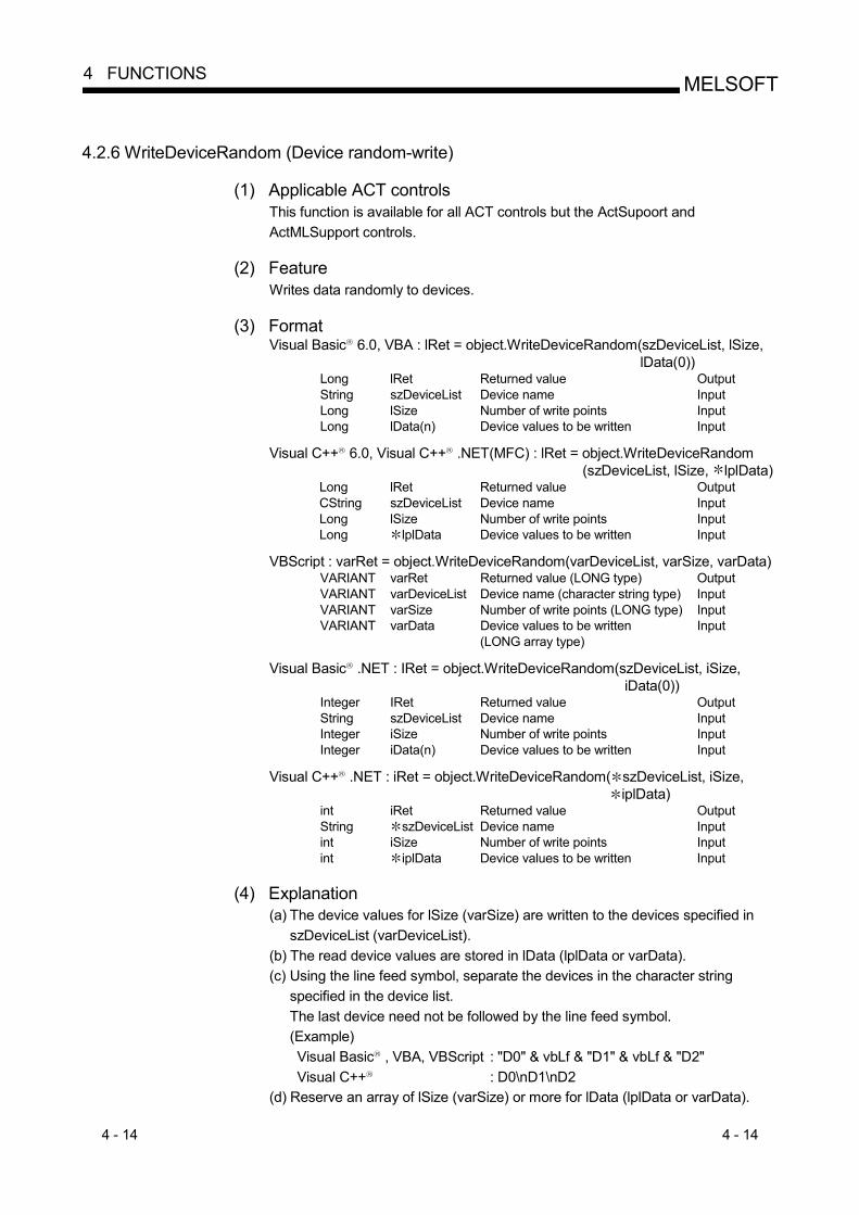
4 - 14 4 - 14
MELSOFT4 FUNCTIONS
4.2.6 WriteDeviceRandom (Device random-write)
(1) Applicable ACT controls This function is available for all ACT controls but the ActSupoort and ActMLSupport controls.
(2) Feature
Writes data randomly to devices.
(3) Format Visual Basic R 6.0, VBA : lRet = object.WriteDeviceRandom(szDeviceList, lSize,
lData(0)) Long lRet Returned value Output String szDeviceList Device name Input Long lSize Number of write points Input Long lData(n) Device values to be written Input
Visual C++ R 6.0, Visual C++ R .NET(MFC) : lRet = object.WriteDeviceRandom
(szDeviceList, lSize, lplData) Long lRet Returned value Output CString szDeviceList Device name Input Long lSize Number of write points Input Long lplData Device values to be written Input
VBScript : varRet = object.WriteDeviceRandom(varDeviceList, varSize, varData)
VARIANT varRet Returned value (LONG type) Output VARIANT varDeviceList Device name (character string type) Input VARIANT varSize Number of write points (LONG type) Input VARIANT varData Device values to be written
(LONG array type) Input
Visual Basic R .NET : IRet = object.WriteDeviceRandom(szDeviceList, iSize,
iData(0)) Integer IRet Returned value Output String szDeviceList Device name Input Integer iSize Number of write points Input Integer iData(n) Device values to be written Input
Visual C++ R .NET : iRet = object.WriteDeviceRandom( szDeviceList, iSize,
iplData) int iRet Returned value Output String szDeviceList Device name Input int iSize Number of write points Input int iplData Device values to be written Input
(4) Explanation
(a) The device values for lSize (varSize) are written to the devices specified in szDeviceList (varDeviceList).
(b) The read device values are stored in lData (lplData or varData). (c) Using the line feed symbol, separate the devices in the character string
specified in the device list. The last device need not be followed by the line feed symbol. (Example) Visual Basic R , VBA, VBScript : "D0" & vbLf & "D1" & vbLf & "D2" Visual C++ R : D0\nD1\nD2
(d) Reserve an array of lSize (varSize) or more for lData (lplData or varData).
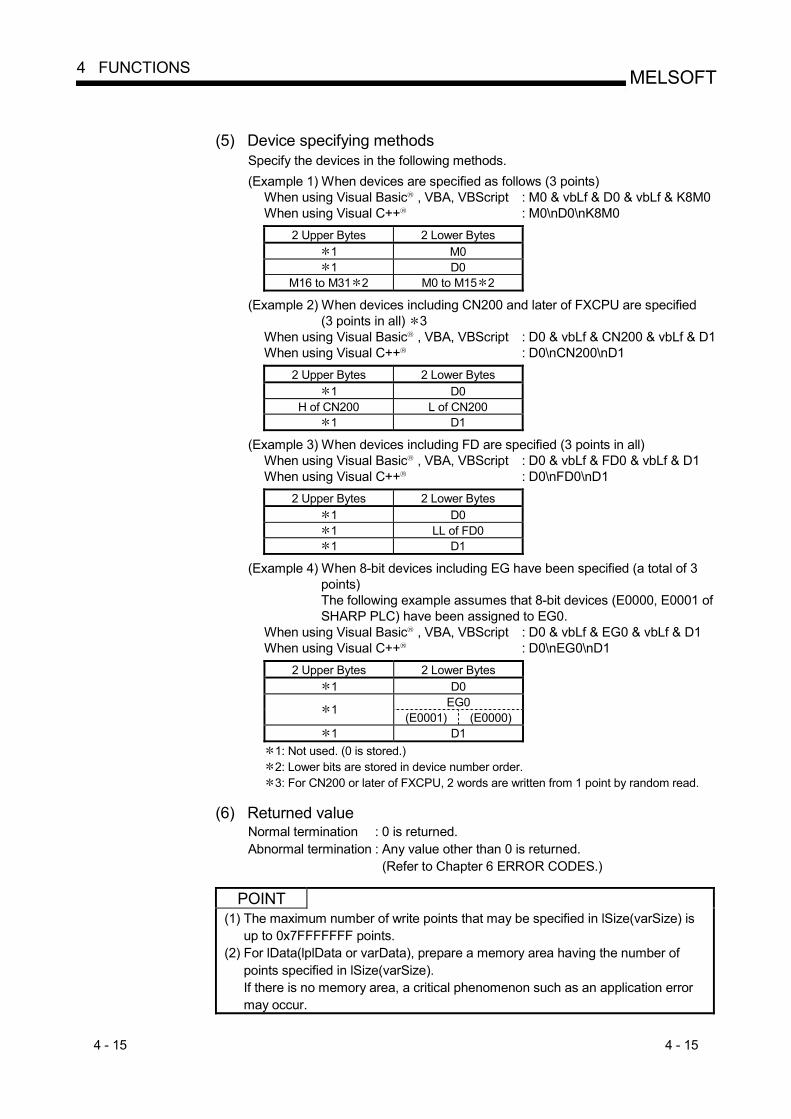
4 - 15 4 - 15
MELSOFT4 FUNCTIONS
(5) Device specifying methods
Specify the devices in the following methods. (Example 1) When devices are specified as follows (3 points)
When using Visual Basic R , VBA, VBScript : M0 & vbLf & D0 & vbLf & K8M0 When using Visual C++ R : M0\nD0\nK8M0
2 Upper Bytes 2 Lower Bytes 1 M0 1 D0
M16 to M31 2 M0 to M15 2 (Example 2) When devices including CN200 and later of FXCPU are specified
(3 points in all) 3 When using Visual Basic R , VBA, VBScript : D0 & vbLf & CN200 & vbLf & D1 When using Visual C++ R : D0\nCN200\nD1
2 Upper Bytes 2 Lower Bytes 1 D0
H of CN200 L of CN200 1 D1
(Example 3) When devices including FD are specified (3 points in all) When using Visual Basic R , VBA, VBScript : D0 & vbLf & FD0 & vbLf & D1 When using Visual C++ R : D0\nFD0\nD1
2 Upper Bytes 2 Lower Bytes 1 D0 1 LL of FD0 1 D1
(Example 4) When 8-bit devices including EG have been specified (a total of 3 points) The following example assumes that 8-bit devices (E0000, E0001 of SHARP PLC) have been assigned to EG0.
When using Visual Basic R , VBA, VBScript : D0 & vbLf & EG0 & vbLf & D1 When using Visual C++ R : D0\nEG0\nD1
2 Upper Bytes 2 Lower Bytes 1 D0
EG0 1 (E0001) (E0000)
1 D1 1: Not used. (0 is stored.) 2: Lower bits are stored in device number order. 3: For CN200 or later of FXCPU, 2 words are written from 1 point by random read.
(6) Returned value
Normal termination : 0 is returned. Abnormal termination : Any value other than 0 is returned.
(Refer to Chapter 6 ERROR CODES.)
POINT (1) The maximum number of write points that may be specified in lSize(varSize) is
up to 0x7FFFFFFF points. (2) For lData(lplData or varData), prepare a memory area having the number of
points specified in lSize(varSize). If there is no memory area, a critical phenomenon such as an application error may occur.

4 - 16 4 - 16
MELSOFT4 FUNCTIONS
4.2.7 SetDevice (Device data setting)
(1) Applicable ACT controls This function is available for all ACT controls but the ActSupoort and ActMLSupport controls.
(2) Feature
Sets one point of device.
(3) Format Visual Basic R 6.0, VBA : lRet = object.SetDevice(Device, lData)
Long lRet Returned value Output String szDevice Device name Input Long lData Set data Input
Visual C++ R 6.0, Visual C++ R .NET(MFC) : lRet = object.SetDevice(szDevice,
lData) Long lRet Returned value Output CString szDevice Device name Input Long lData Set data Input
VBScript : varRet = object.SetDevice(varDevice, lpvarData)
VARIANT varRet Returned value (LONG type) Output VARIANT varDevice Device name
(character string type) Input
VARIANT varData Set data (LONG type) Input
Visual Basic R .NET : IRet = object.SetDevice(szDevice, iData) Integer IRet Returned value Output String szDevice Device name Input Integer iData Set Data Input
Visual C++ R .NET : iRet = object.SetDevice( szDevice, iData)
int iRet Returned value Output String szDevice Device name Input int iData Set Data Input
(4) Explanation
(a) The operation specified in lData(varData) is performed for one point of device specified in szDevice(varDevice).
(b) When the bit device is specified, the least significant bit of the lData value (varData value) becomes valid.

4 - 17 4 - 17
MELSOFT4 FUNCTIONS
(5) Device specifying methods
Specify the devices in the following methods.
<When bit device is specified> <When word device is specified> (Example) M0 (Example) D0
2 Upper Bytes 2 Lower Bytes 2 Upper Bytes 2 Lower Bytes 1 M0 1 D0
<When double-word device is specified> <When CN200 or later of FXCPU is specified>
(Example) K8M0 (Example) CN200 2 Upper Bytes 2 Lower Bytes 2 Upper Bytes 2 Lower Bytes M16 to M31 2 M0 to M15 2 H of CN200 L of CN200
<When gateway device is specified>
(Example) When 8-bit devices (E0000, E0001 of SHARP PLC) have been assigned to EG0 2 Upper Bytes 2 Lower Bytes
EG0 1 (E0001) (E0000)
1: Not used. (0 is stored.) 2: Lower bits are stored in device number order.
(6) Returned value
Normal termination : 0 is returned. Abnormal termination : Any value other than 0 is returned.
(Refer to Chapter 6 ERROR CODES.)
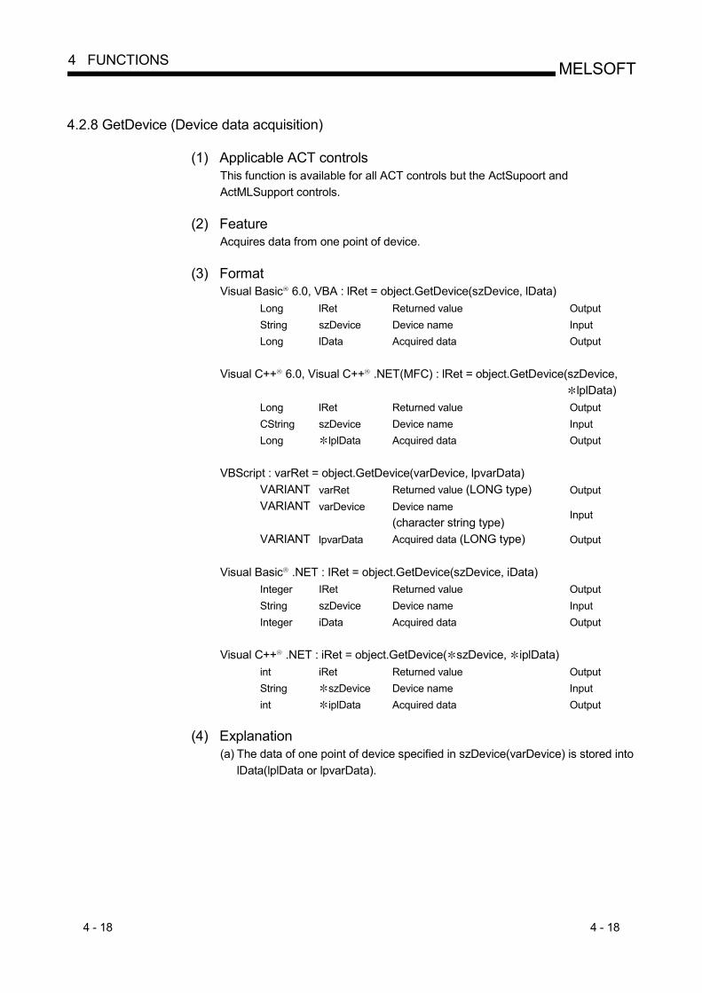
4 - 18 4 - 18
MELSOFT4 FUNCTIONS
4.2.8 GetDevice (Device data acquisition)
(1) Applicable ACT controls This function is available for all ACT controls but the ActSupoort and ActMLSupport controls.
(2) Feature
Acquires data from one point of device.
(3) Format Visual Basic R 6.0, VBA : lRet = object.GetDevice(szDevice, lData)
Long lRet Returned value Output String szDevice Device name Input Long lData Acquired data Output
Visual C++ R 6.0, Visual C++ R .NET(MFC) : lRet = object.GetDevice(szDevice,
lplData) Long lRet Returned value Output CString szDevice Device name Input Long lplData Acquired data Output
VBScript : varRet = object.GetDevice(varDevice, lpvarData)
VARIANT varRet Returned value (LONG type) Output VARIANT varDevice Device name
(character string type) Input
VARIANT lpvarData Acquired data (LONG type) Output
Visual Basic R .NET : IRet = object.GetDevice(szDevice, iData) Integer IRet Returned value Output String szDevice Device name Input Integer iData Acquired data Output
Visual C++ R .NET : iRet = object.GetDevice( szDevice, iplData)
int iRet Returned value Output String szDevice Device name Input int iplData Acquired data Output
(4) Explanation
(a) The data of one point of device specified in szDevice(varDevice) is stored into lData(lplData or lpvarData).

4 - 19 4 - 19
MELSOFT4 FUNCTIONS
(5) Device specifying methods
Specify the devices in the following methods.
<When bit device is specified> <When word device is specified> (Example) M0 (Example) D0
2 Upper Bytes 2 Lower Bytes 2 Upper Bytes 2 Lower Bytes 1 M0 1 D0
<When double-word device is specified> <When CN200 or later of FXCPU is specified>
(Example) K8M0 (Example) CN200 2 Upper Bytes 2 Lower Bytes 2 Upper Bytes 2 Lower Bytes M16 to M31 2 M0 to M15 2 H of CN200 L of CN200
<When gateway device is specified>
(Example) When 8-bit devices (E0000, E0001 of SHARP PLC) have been assigned to EG0 2 Upper Bytes 2 Lower Bytes
EG0 1 (E0001) (E0000)
1: Not used. (0 is stored.) 2: Lower bits are stored in device number order.
(6) Returned value
Normal termination : 0 is returned. Abnormal termination : Any value other than 0 is returned.
(Refer to Chapter 6 ERROR CODES.)
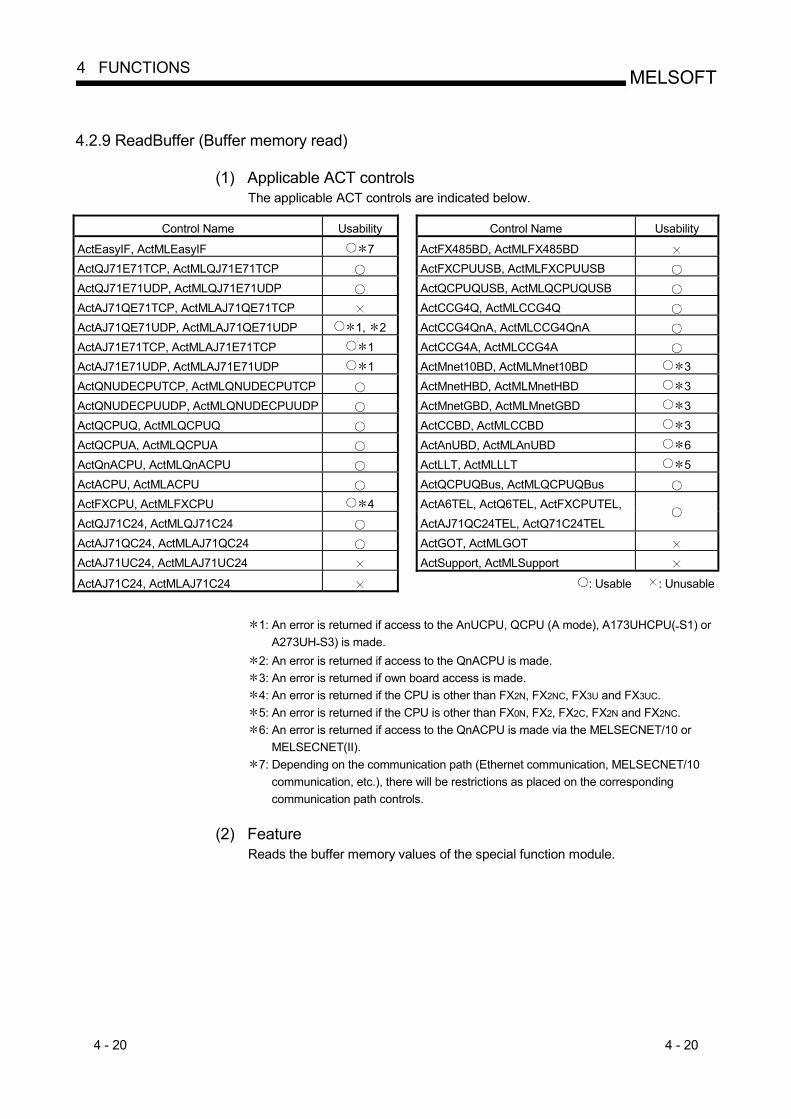
4 - 20 4 - 20
MELSOFT4 FUNCTIONS
4.2.9 ReadBuffer (Buffer memory read)
(1) Applicable ACT controls The applicable ACT controls are indicated below.
Control Name Usability Control Name Usability
ActEasyIF, ActMLEasyIF 7 ActFX485BD, ActMLFX485BD ActQJ71E71TCP, ActMLQJ71E71TCP ActFXCPUUSB, ActMLFXCPUUSB ActQJ71E71UDP, ActMLQJ71E71UDP ActQCPUQUSB, ActMLQCPUQUSB ActAJ71QE71TCP, ActMLAJ71QE71TCP ActCCG4Q, ActMLCCG4Q ActAJ71QE71UDP, ActMLAJ71QE71UDP 1, 2 ActCCG4QnA, ActMLCCG4QnA ActAJ71E71TCP, ActMLAJ71E71TCP 1 ActCCG4A, ActMLCCG4A ActAJ71E71UDP, ActMLAJ71E71UDP 1 ActMnet10BD, ActMLMnet10BD 3 ActQNUDECPUTCP, ActMLQNUDECPUTCP ActMnetHBD, ActMLMnetHBD 3 ActQNUDECPUUDP, ActMLQNUDECPUUDP ActMnetGBD, ActMLMnetGBD 3 ActQCPUQ, ActMLQCPUQ ActCCBD, ActMLCCBD 3 ActQCPUA, ActMLQCPUA ActAnUBD, ActMLAnUBD 6 ActQnACPU, ActMLQnACPU ActLLT, ActMLLLT 5 ActACPU, ActMLACPU ActQCPUQBus, ActMLQCPUQBus ActFXCPU, ActMLFXCPU 4 ActA6TEL, ActQ6TEL, ActFXCPUTEL, ActQJ71C24, ActMLQJ71C24 ActAJ71QC24TEL, ActQ71C24TEL
ActAJ71QC24, ActMLAJ71QC24 ActGOT, ActMLGOT ActAJ71UC24, ActMLAJ71UC24 ActSupport, ActMLSupport ActAJ71C24, ActMLAJ71C24 : Usable : Unusable
1: An error is returned if access to the AnUCPU, QCPU (A mode), A173UHCPU(-S1) or
A273UH-S3) is made. 2: An error is returned if access to the QnACPU is made. 3: An error is returned if own board access is made. 4: An error is returned if the CPU is other than FX2N, FX2NC, FX3U and FX3UC. 5: An error is returned if the CPU is other than FX0N, FX2, FX2C, FX2N and FX2NC. 6: An error is returned if access to the QnACPU is made via the MELSECNET/10 or
MELSECNET(II). 7: Depending on the communication path (Ethernet communication, MELSECNET/10
communication, etc.), there will be restrictions as placed on the corresponding communication path controls.
(2) Feature
Reads the buffer memory values of the special function module.

4 - 21 4 - 21
MELSOFT4 FUNCTIONS
(3) Format
Visual Basic R 6.0, VBA :lRet = object.ReadBuffer(lStartIO, lAddress, lReadSize, iData(0))
Long lRet Returned value Output Long lStartIO First I/O number of module from
where values will be read Input
Long lAddress Buffer memory address Input Long lReadSize Read size Input Integer iData(n) Values read from buffer memory Output
Visual C++ R 6.0, Visual C++ R .NET(MFC) :lRet = object.ReadBuffer
(lStartIO, lAddress, lReadSize lpsData)
Long lRet Returned value Output Long lStartIO First I/O number of module from
where values will be read Input
Long lAddress Buffer memory address Input Long lReadSize Read size Input Short lpsData Values read from buffer memory Output
VBScript :varRet = object.ReadBuffer(varStartIO, varAddress, varReadSize,
lpvarData) VARIANT varRet Returned value(LONG type) Output VARIANT varStartIO First I/O number of module from
where values will be read (LONG type)
Input
VARIANT varAddress Buffer memory address(LONG type) Input VARIANT varReadSize Read size(LONG type) Input VARIANT lpvarData Values read from buffer memory
(SHORT array type) Output
Visual Basic R .NET : IRet = object.ReadBuffer(iStartIO, iAddress, iReadSize,
iData(0)) Integer IRet Returned value Output Integer iStartIO First I/O number of module form Input Integer iAddress Buffer memory address Input Integer iReadSize Read size Input short iData(n) Values read from buffer memory Output
Visual C++ R .NET : iRet = object.ReadBuffer(iStartIO, iAddress, iReadSize,
ipsData) int iRet Returned value Output int iStartIO First I/O number of module form Input int iAddress Buffer memory address Input int iReadSize Read size Input short ipsData Values read from buffer memory Output

4 - 22 4 - 22
MELSOFT4 FUNCTIONS
(4) Explanation
(a) As the module I/O number specified in lStartIO(varStartIO), specify a value found by dividing the actual I/O number by 16.
(b) The buffer values for lReadSize(varReadSize) at the buffer memory address specified in lAddress(varAddress) in the special function module located at the first I/O number specified in lStartIO(varStartIO) are read.
(c) When using the Act(ML)FXCPU control or Act(ML)LLT control, specify the block number (0 to 7) of the special expansion equipment as the module's first I/O number and any of 0 to 32767 as the buffer memory address.
(d) Reserve an array of lReadSize (varReadSize) or more for iData (lplData or lpvarData).
(5) Returned value
Normal termination : 0 is returned. Abnormal termination : Any value other than 0 is returned.
(Refer to Chapter 6 ERROR CODES.)
(6) Instructions for read/write of data from/to buffer memory in multiple PLC system configuration The following phenomena will occur when the function is executed if the actually configured multiple PLC system differs from the I/O assignment set using GX Developer. Execute the function after checking the I/O assignment on GX Developer and checking the I/O numbers of the module from/to where the value will be read/written. (a) An error occurs if the function is executed after the correct I/O numbers have
been specified. (b) When the specific I/O numbers (I/O numbers whose I/O assignment is
actually wrong) are specified, read from buffer memory can be performed properly, but write to buffer memory results in an error (error code: 0x010A4030, 0x010A4042, etc.).
(c) Though a PLC CPU error (parameter error, SP. UNIT LAY ERR, etc.) does not occur in the multiple PLC system, execution of the function results in an error in the user application.
POINT
(1) An error is returned if access to the motion controller CPU is made. (2) For iData (lpsData or lpvarData), prepare a memory area having the number of
points specified in lReadSize(varReadSize). If there is no memory area, a critical phenomenon such as an application error may occur.
(3) When buffer memory read (ReadBuffer) is performed for the QCPU (Q mode), read operation may be performed for only the Q series-dedicated module. Read from the shared memory of the QCPU (Q mode) cannot be performed, either.
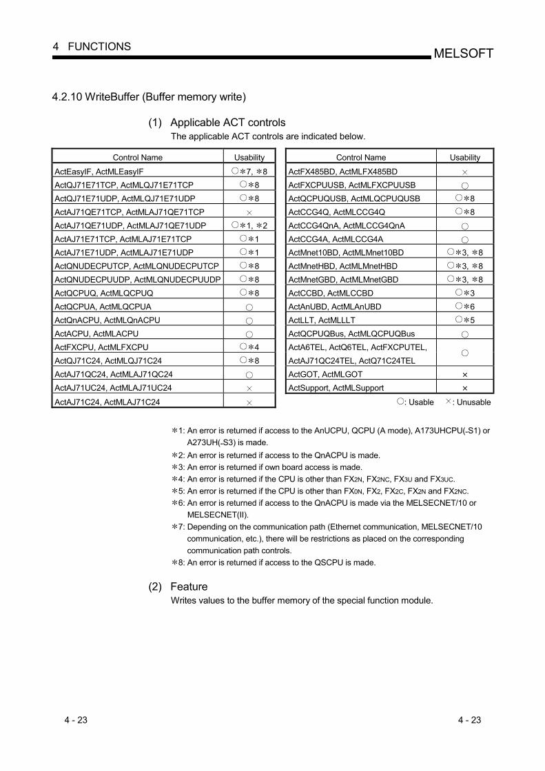
4 - 23 4 - 23
MELSOFT4 FUNCTIONS
4.2.10 WriteBuffer (Buffer memory write)
(1) Applicable ACT controls The applicable ACT controls are indicated below.
Control Name Usability Control Name Usability
ActEasyIF, ActMLEasyIF 7, 8 ActFX485BD, ActMLFX485BD ActQJ71E71TCP, ActMLQJ71E71TCP 8 ActFXCPUUSB, ActMLFXCPUUSB ActQJ71E71UDP, ActMLQJ71E71UDP 8 ActQCPUQUSB, ActMLQCPUQUSB 8 ActAJ71QE71TCP, ActMLAJ71QE71TCP ActCCG4Q, ActMLCCG4Q 8 ActAJ71QE71UDP, ActMLAJ71QE71UDP 1, 2 ActCCG4QnA, ActMLCCG4QnA ActAJ71E71TCP, ActMLAJ71E71TCP 1 ActCCG4A, ActMLCCG4A ActAJ71E71UDP, ActMLAJ71E71UDP 1 ActMnet10BD, ActMLMnet10BD 3, 8 ActQNUDECPUTCP, ActMLQNUDECPUTCP 8 ActMnetHBD, ActMLMnetHBD 3, 8 ActQNUDECPUUDP, ActMLQNUDECPUUDP 8 ActMnetGBD, ActMLMnetGBD 3, 8 ActQCPUQ, ActMLQCPUQ 8 ActCCBD, ActMLCCBD 3 ActQCPUA, ActMLQCPUA ActAnUBD, ActMLAnUBD 6 ActQnACPU, ActMLQnACPU ActLLT, ActMLLLT 5 ActACPU, ActMLACPU ActQCPUQBus, ActMLQCPUQBus ActFXCPU, ActMLFXCPU 4 ActA6TEL, ActQ6TEL, ActFXCPUTEL, ActQJ71C24, ActMLQJ71C24 8 ActAJ71QC24TEL, ActQ71C24TEL
ActAJ71QC24, ActMLAJ71QC24 ActGOT, ActMLGOT ActAJ71UC24, ActMLAJ71UC24 ActSupport, ActMLSupport ActAJ71C24, ActMLAJ71C24 : Usable : Unusable
1: An error is returned if access to the AnUCPU, QCPU (A mode), A173UHCPU(-S1) or
A273UH(-S3) is made. 2: An error is returned if access to the QnACPU is made. 3: An error is returned if own board access is made. 4: An error is returned if the CPU is other than FX2N, FX2NC, FX3U and FX3UC. 5: An error is returned if the CPU is other than FX0N, FX2, FX2C, FX2N and FX2NC. 6: An error is returned if access to the QnACPU is made via the MELSECNET/10 or
MELSECNET(II). 7: Depending on the communication path (Ethernet communication, MELSECNET/10
communication, etc.), there will be restrictions as placed on the corresponding communication path controls.
8: An error is returned if access to the QSCPU is made.
(2) Feature Writes values to the buffer memory of the special function module.
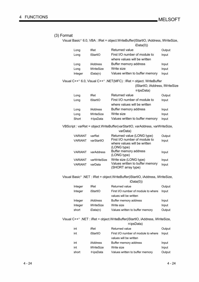
4 - 24 4 - 24
MELSOFT4 FUNCTIONS
(3) Format
Visual Basic R 6.0, VBA : lRet = object.WriteBuffer(lStartIO, lAddress, lWriteSize, iData(0))
Long lRet Returned value Output Long lStartIO First I/O number of module to
where values will be written Input
Long lAddress Buffer memory address Input Long lWriteSize Write size Input Integer iData(n) Values written to buffer memory Input
Visual C++ R 6.0, Visual C++ R .NET(MFC) : lRet = object. WriteBuffer
(lStartIO, lAddress, lWriteSize lpsData)
Long lRet Returned value Output Long lStartIO First I/O number of module to
where values will be written Input
Long lAddress Buffer memory address Input Long lWriteSize Write size Input Short lpsData Values written to buffer memory Input
VBScript : varRet = object.WriteBuffer(varStartIO, varAddress, varWriteSize,
varData) VARIANT varRet Returned value (LONG type) Output VARIANT varStartIO First I/O number of module to
where values will be written (LONG type)
Input
VARIANT varAddress Buffer memory address (LONG type)
Input
VARIANT varWriteSize Write size (LONG type) Input VARIANT varData Values written to buffer memory
(SHORT array type) Input
Visual Basic R .NET : IRet = object.WriteBuffer(iStartIO, iAddress, iWriteSize,
iData(0)) Integer IRet Returned value Output Integer iStartIO First I/O number of module to where
values will be written Input
Integer iAddress Buffer memory address Input Integer iWriteSize Write size Input short iData(n) Values written to buffer memory Output
Visual C++ R .NET : iRet = object.WriteBuffer(iStartIO, iAddress, iWriteSize,
ipsData) int iRet Returned value Output int iStartIO First I/O number of module to where
values will be written Input
int iAddress Buffer memory address Input int iWriteSize Write size Input short ipsData Values written to buffer memory Output
4 - 25 4 - 25
MELSOFT4 FUNCTIONS
(4) Explanation
(a) As the module I/O number specified in lStartIO(varStartIO), specify a value found by dividing the actual I/O number by 16.
(b) The buffer values for lWriteSize(varWriteSize) at the buffer memory address specified in lAddress(varAddress) in the special function module located at the first I/O number specified in lStartIO(varStartIO) are written.
(c) When using the Act(ML)FXCPU control or Act(ML)LLT control, specify the block number (0 to 7) of the special expansion equipment as the module's first I/O number and any of 0 to 32767 as the buffer memory address.
(d) Reserve an array of lWriteSize (varWriteSize) or more for iData (lpsData or varData).
(5) Returned value
Normal termination : 0 is returned. Abnormal termination : Any value other than 0 is returned.
(Refer to Chapter 6 ERROR CODES.)
(6) Instructions for read/write of data from/to buffer memory in multiple PLC system configuration The following phenomena will occur when the function is executed if the actually configured multiple PLC system differs from the I/O assignment set using GX Developer. Execute the function after checking the I/O assignment on GX Developer and checking the I/O numbers of the module from/to where the value will be read/written. (a) An error occurs if the function is executed after the correct I/O numbers have
been specified. (b) When the specific I/O numbers (I/O numbers whose I/O assignment is
actually wrong) are specified, read from buffer memory can be performed properly, but write to buffer memory results in an error (error code: 0x010A4030, 0x010A4042, etc.).
(c) Though a PLC CPU error (parameter error, SP. UNIT LAY ERR, etc.) does not occur in the multiple PLC system, execution of the function results in an error in the user application.
POINT
(1) An error is returned if access to the motion controller CPU is made. (2) For iData(lpsData,varData), prepare a memory area having the number of
points specified in lWriteSize(varWriteSize). If there is no memory area, a critical phenomenon such as an application error may occur.
(3) When buffer memory write (WriteBuffer) is performed for the QCPU (Q mode), write operation may be performed for only the Q series-dedicated module. Write to the shared memory of the QCPU (Q mode) cannot be performed, either.

4 - 26 4 - 26
MELSOFT4 FUNCTIONS
4.2.11 GetClockData (Clock data read)
(1) Applicable ACT controls The applicable ACT controls are indicated below.
Control Name Usability Control Name Usability
ActEasyIF, ActMLEasyIF 4 ActFX485BD, ActMLFX485BD ActQJ71E71TCP, ActMLQJ71E71TCP ActFXCPUUSB, ActMLFXCPUUSB ActQJ71E71UDP, ActMLQJ71E71UDP ActQCPUQUSB, ActMLQCPUQUSB ActAJ71QE71TCP, ActMLAJ71QE71TCP ActCCG4Q, ActMLCCG4Q ActAJ71QE71UDP, ActMLAJ71QE71UDP ActCCG4QnA, ActMLCCG4QnA ActAJ71E71TCP, ActMLAJ71E71TCP 2 ActCCG4A, ActMLCCG4A ActAJ71E71UDP, ActMLAJ71E71UDP 2 ActMnet10BD, ActMLMnet10BD 1 ActQNUDECPUTCP, ActMLQNUDECPUTCP ActMnetHBD, ActMLMnetHBD 1 ActQNUDECPUUDP, ActMLQNUDECPUUDP ActMnetGBD, ActMLMnetGBD 1 ActQCPUQ, ActMLQCPUQ ActCCBD, ActMLCCBD 1 ActQCPUA, ActMLQCPUA ActAnUBD, ActMLAnUBD 3 ActQnACPU, ActMLQnACPU ActLLT, ActMLLLT ActACPU, ActMLACPU ActQCPUQBus, ActMLQCPUQBus ActFXCPU, ActMLFXCPU ActA6TEL, ActQ6TEL, ActFXCPUTEL, ActQJ71C24, ActMLQJ71C24 ActAJ71QC24TEL, ActQ71C24TEL
ActAJ71QC24, ActMLAJ71QC24 2 ActGOT, ActMLGOT ActAJ71UC24, ActMLAJ71UC24 2 ActSupport, ActMLSupport ActAJ71C24, ActMLAJ71C24 : Usable : Unusable
1: An error is returned if own board access is made. 2: An error is returned if access to the QnACPU is made. 3: An error is returned if access to the QnACPU is made via the MELSECNET/10 or
MELSECNET(II). 4: Depending on the communication path (Ethernet communication, MELSECNET/10
communication, etc.), there will be restrictions as placed on the corresponding communication path controls.
(2) Feature
Reads time from the clock data of the PLC CPU.
(3) Format Visual Basic R 6.0, VBA : lRet = object.GetClockData(iYear, iMonth, iDay,
iDayOfWeek, iHour, iMinute, iSecond) Long lRet Returned value Output Integer iYear Read year value Output Integer iManth Read month value Output Integer iDay Read day value Output Integer iDayOfWeek Read day-of-week value Output Integer iHour Read hour value Output Integer iMinute Read minute value Output Integer iSecond Read second value Output
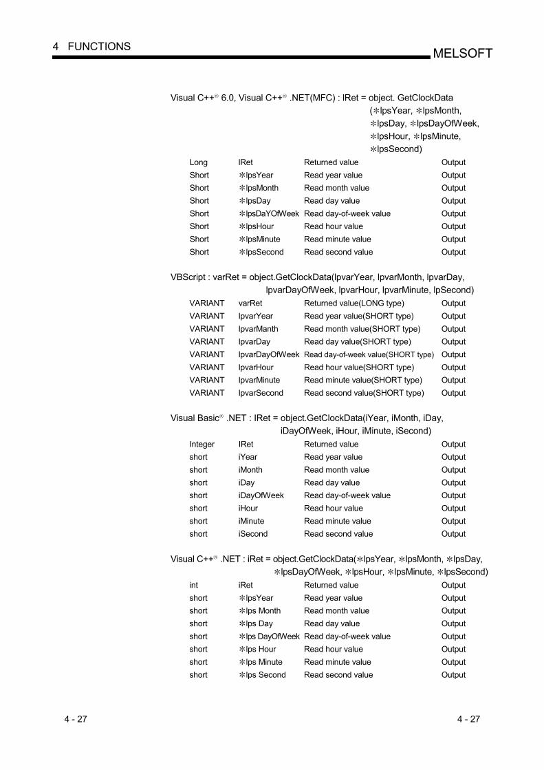
4 - 27 4 - 27
MELSOFT4 FUNCTIONS
Visual C++ R 6.0, Visual C++ R .NET(MFC) : lRet = object. GetClockData
( lpsYear, lpsMonth, lpsDay, lpsDayOfWeek, lpsHour, lpsMinute, lpsSecond)
Long lRet Returned value Output Short lpsYear Read year value Output Short lpsMonth Read month value Output Short lpsDay Read day value Output Short lpsDaYOfWeek Read day-of-week value Output Short lpsHour Read hour value Output Short lpsMinute Read minute value Output Short lpsSecond Read second value Output
VBScript : varRet = object.GetClockData(lpvarYear, lpvarMonth, lpvarDay,
lpvarDayOfWeek, lpvarHour, lpvarMinute, lpSecond) VARIANT varRet Returned value(LONG type) Output VARIANT lpvarYear Read year value(SHORT type) Output VARIANT lpvarManth Read month value(SHORT type) Output VARIANT lpvarDay Read day value(SHORT type) Output VARIANT lpvarDayOfWeek Read day-of-week value(SHORT type) Output VARIANT lpvarHour Read hour value(SHORT type) Output VARIANT lpvarMinute Read minute value(SHORT type) Output VARIANT lpvarSecond Read second value(SHORT type) Output
Visual Basic R .NET : IRet = object.GetClockData(iYear, iMonth, iDay,
iDayOfWeek, iHour, iMinute, iSecond) Integer IRet Returned value Output short iYear Read year value Output short iMonth Read month value Output short iDay Read day value Output short iDayOfWeek Read day-of-week value Output short iHour Read hour value Output short iMinute Read minute value Output short iSecond Read second value Output
Visual C++ R .NET : iRet = object.GetClockData( lpsYear, lpsMonth, lpsDay,
lpsDayOfWeek, lpsHour, lpsMinute, lpsSecond) int iRet Returned value Output short lpsYear Read year value Output short lps Month Read month value Output short lps Day Read day value Output short lps DayOfWeek Read day-of-week value Output short lps Hour Read hour value Output short lps Minute Read minute value Output short lps Second Read second value Output
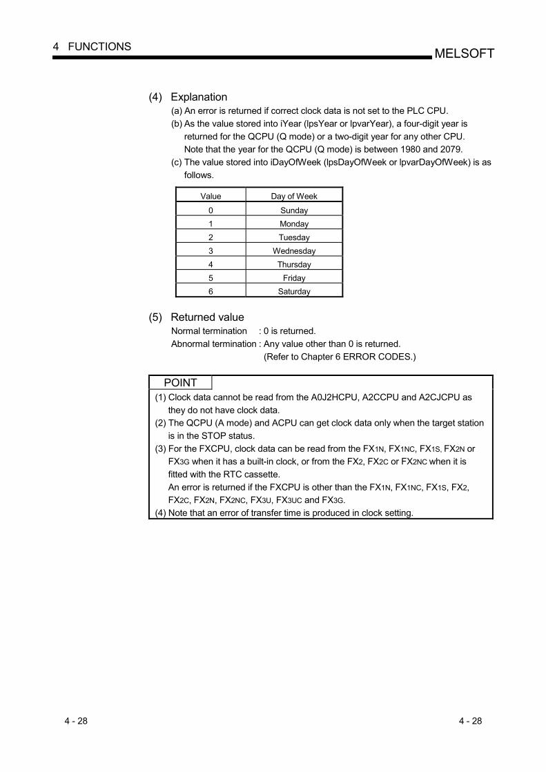
4 - 28 4 - 28
MELSOFT4 FUNCTIONS
(4) Explanation
(a) An error is returned if correct clock data is not set to the PLC CPU. (b) As the value stored into iYear (lpsYear or lpvarYear), a four-digit year is
returned for the QCPU (Q mode) or a two-digit year for any other CPU. Note that the year for the QCPU (Q mode) is between 1980 and 2079.
(c) The value stored into iDayOfWeek (lpsDayOfWeek or lpvarDayOfWeek) is as follows.
Value Day of Week
0 Sunday 1 Monday 2 Tuesday 3 Wednesday 4 Thursday 5 Friday 6 Saturday
(5) Returned value
Normal termination : 0 is returned. Abnormal termination : Any value other than 0 is returned.
(Refer to Chapter 6 ERROR CODES.)
POINT (1) Clock data cannot be read from the A0J2HCPU, A2CCPU and A2CJCPU as
they do not have clock data. (2) The QCPU (A mode) and ACPU can get clock data only when the target station
is in the STOP status. (3) For the FXCPU, clock data can be read from the FX1N, FX1NC, FX1S, FX2N or
FX3G when it has a built-in clock, or from the FX2, FX2C or FX2NC when it is fitted with the RTC cassette. An error is returned if the FXCPU is other than the FX1N, FX1NC, FX1S, FX2, FX2C, FX2N, FX2NC, FX3U, FX3UC and FX3G.
(4) Note that an error of transfer time is produced in clock setting.

4 - 29 4 - 29
MELSOFT4 FUNCTIONS
4.2.12 SetClockData (Clock data write)
(1) Applicable ACT controls The applicable ACT controls are indicated below.
Control Name Usability Control Name Usability
ActEasyIF, ActMLEasyIF 4, 5 ActFX485BD, ActMLFX485BD ActQJ71E71TCP, ActMLQJ71E71TCP 5 ActFXCPUUSB, ActMLFXCPUUSB ActQJ71E71UDP, ActMLQJ71E71UDP 5 ActQCPUQUSB, ActMLQCPUQUSB 5 ActAJ71QE71TCP, ActMLAJ71QE71TCP ActCCG4Q, ActMLCCG4Q 5 ActAJ71QE71UDP, ActMLAJ71QE71UDP ActCCG4QnA, ActMLCCG4QnA ActAJ71E71TCP, ActMLAJ71E71TCP 2 ActCCG4A, ActMLCCG4A ActAJ71E71UDP, ActMLAJ71E71UDP 2 ActMnet10BD, ActMLMnet10BD 1, 5 ActQNUDECPUTCP, ActMLQNUDECPUTCP 5 ActMnetHBD, ActMLMnetHBD 1, 5 ActQNUDECPUUDP, ActMLQNUDECPUUDP 5 ActMnetGBD, ActMLMnetGBD 1, 5 ActQCPUQ, ActMLQCPUQ 5 ActCCBD, ActMLCCBD 1, 5 ActQCPUA, ActMLQCPUA ActAnUBD, ActMLAnUBD 3 ActQnACPU, ActMLQnACPU ActLLT, ActMLLLT ActACPU, ActMLACPU ActQCPUQBus, ActMLQCPUQBus ActFXCPU, ActMLFXCPU ActA6TEL, ActQ6TEL, ActFXCPUTEL, ActQJ71C24, ActMLQJ71C24 5 ActAJ71QC24TEL, ActQ71C24TEL
ActAJ71QC24, ActMLAJ71QC24 2 ActGOT, ActMLGOT ActAJ71UC24, ActMLAJ71UC24 2 ActSupport, ActMLSupport ActAJ71C24, ActMLAJ71C24 : Usable : Unusable
1: An error is returned if own board access is made. 2: An error is returned if access to the QnACPU is made. 3: An error is returned if access to the QnACPU is made via the MELSECNET/10 or
MELSECNET(II). 4: Depending on the communication path (Ethernet communication, MELSECNET/10
communication, etc.), there will be restrictions as placed on the corresponding communication path controls.
5: An error is returned if access to the QSCPU is made.
(2) Feature Writes time to the clock data of the PLC CPU.
(3) Format
Visual Basic R 6.0, VBA : lRet = object.SetClockData(iYear, iMonth, iDay, iDayOfWeek, iHour, iMinute, iSecond)
Long lRet Returned value Output Integer iYear Year value to be written Input Integer iManth Month value to be written Input Integer iDay Day value to be written Input Integer iDayOfWeek Day-of-week value to be written Input Integer iHour Hour value to be written Input Integer iMinute Minute value to be written Input Integer iSecond Second value to be written Input
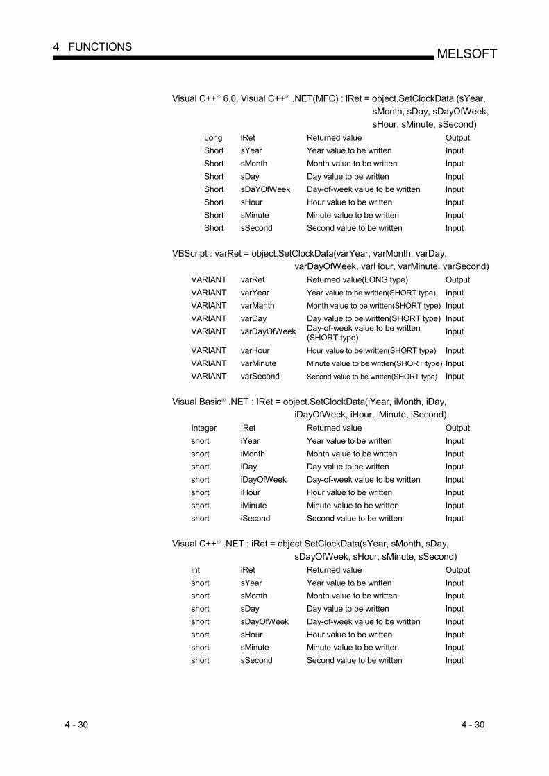
4 - 30 4 - 30
MELSOFT4 FUNCTIONS
Visual C++ R 6.0, Visual C++ R .NET(MFC) : lRet = object.SetClockData (sYear,
sMonth, sDay, sDayOfWeek, sHour, sMinute, sSecond)
Long lRet Returned value Output Short sYear Year value to be written Input Short sMonth Month value to be written Input Short sDay Day value to be written Input Short sDaYOfWeek Day-of-week value to be written Input Short sHour Hour value to be written Input Short sMinute Minute value to be written Input Short sSecond Second value to be written Input
VBScript : varRet = object.SetClockData(varYear, varMonth, varDay,
varDayOfWeek, varHour, varMinute, varSecond) VARIANT varRet Returned value(LONG type) Output VARIANT varYear Year value to be written(SHORT type) Input VARIANT varManth Month value to be written(SHORT type) Input VARIANT varDay Day value to be written(SHORT type) Input VARIANT varDayOfWeek Day-of-week value to be written
(SHORT type) Input
VARIANT varHour Hour value to be written(SHORT type) Input VARIANT varMinute Minute value to be written(SHORT type) Input VARIANT varSecond Second value to be written(SHORT type) Input
Visual Basic R .NET : IRet = object.SetClockData(iYear, iMonth, iDay,
iDayOfWeek, iHour, iMinute, iSecond) Integer IRet Returned value Output short iYear Year value to be written Input short iMonth Month value to be written Input short iDay Day value to be written Input short iDayOfWeek Day-of-week value to be written Input short iHour Hour value to be written Input short iMinute Minute value to be written Input short iSecond Second value to be written Input
Visual C++ R .NET : iRet = object.SetClockData(sYear, sMonth, sDay,
sDayOfWeek, sHour, sMinute, sSecond) int iRet Returned value Output short sYear Year value to be written Input short sMonth Month value to be written Input short sDay Day value to be written Input short sDayOfWeek Day-of-week value to be written Input short sHour Hour value to be written Input short sMinute Minute value to be written Input short sSecond Second value to be written Input

4 - 31 4 - 31
MELSOFT4 FUNCTIONS
(4) Explanation
(a) An error is returned if the clock data to be set are not correct values. (b) As to the value specified in iYear (sYear or varYear), a four-digit year is valid
for the QCPU (Q mode) or a two-digit year for any other CPU. Note that the year valid for the QCPU (Q mode) is between 1980 and 2079. An error will occur if a four-digit year is set to any CPU other than the QCPU (Q mode).
(c) The value to be specified in iDayOfWeek (sDayOfWeek or varDayOfWeek) is as follows.
Value Day of Week
0 Sunday 1 Monday 2 Tuesday 3 Wednesday 4 Thursday 5 Friday 6 Saturday
(5) Returned value
Normal termination : 0 is returned. Abnormal termination : Any value other than 0 is returned.
(Refer to Chapter 6 ERROR CODES.)
POINT (1) Clock data cannot be read from the A0J2HCPU, A2CCPU and A2CJCPU as
they do not have clock data. (2) For the QCPU (A mode) and ACPU, clock data can be set only when the target
station is in the STOP status. (3) For the QCPU (A mode) and ACPU, the clock setting special relay "M9028"
changes to OFF after clock data setting. (4) For the FXCPU, clock setting can be made to the FX1N, FX1NC, FX1S, FX2N or
FX3G when it has a built-in clock, or to the FX2, FX2C or FX2NC when it is fitted with the RTC cassette. An error is returned if the FXCPU is other than the FX1N, FX1NC, FX1S, FX2, FX2C, FX2N, FX2NC, FX3U, FX3UC and FX3G.
(5) Note that an error of transfer time is produced in clock setting.
4 - 32 4 - 32
MELSOFT4 FUNCTIONS
4.2.13 GetCpuType (PLC CPU type read)
(1) Applicable ACT controls This function is available for all ACT controls 1 but the ActSupoort and ActMLSupport controls.
1: MELSECNET/10 board will result in an error if own board access is made.
(2) Feature Reds the type character string and type code of the PLC CPU, Network Board and GOT.
(3) Format
Visual Basic R 6.0, VBA : lRet = object.GetCpuType(szCpuName, lCpuType) Long lRet Returned value Output String szCpuName PLC CPU type character string Output Long lCpuType PLC CPU type code Output
Visual C++ R 6.0, Visual C++ R .NET(MFC) : lRet = object.GetCpuType
( szCpuType, lplCpuType) Long lRet Returned value Output BSTR szCpuName PLC CPU type character string Output Long lplCpuType PLC CPU type code Output
VBScript : varRet = object.GetCpuType(varCpuName, lpvarCpuCode)
VARIANT varRet Returned value(LONG type) Output VARIANT lpvarCpuName PLC CPU type character string
(character string type) Output
VARIANT lpvarCpuCode PLC CPU type code(LONG type) Output
Visual Basic R .NET : IRet = object.GetCpuType(szCpuName, ICpuType) Integer IRet Returned value Output String szCpuName PLC CPU type character string Output Integer ICpuType PLC CPU type code Output
Visual C++ R .NET : iRet = object.GetCpuType ( szCpuName, iplCpuType)
int iRet Returned value Output String szCpuName PLC CPU type character string Output int iplCpuType PLC CPU type code Output
(4) Explanation
(a) The type of the PLC which is making communication is stored into szCpuName (lpvarCpuName) and its type code into lCpuType (lplCpuType or lpvarCpuCode).
(b) The PLC CPU type character string is returned in UNICODE.

4 - 33 4 - 33
MELSOFT4 FUNCTIONS
(5) CPU type character string and type code
The following table lists the CPU, Network Board and GOT type character strings and type codes read using GetCpuType. (a) Type character string list
Type Character String Type Character String CPU/Network Board/GOT Type CPU/Network
Board Type When GX Simulator
is connected
CPU/Network Board/ GOT Type CPU/Network
Board Type When GX Simulator
is connected Q00JCPU Q00JCPU Q00JCPU A2NCPU A2N A2N Q00UJCPU Q00UJCPU Q00UJCPU A2NCPU-S1 A2N A2N Q00CPU Q00CPU Q00CPU A2SCPU A2S A2N Q00UCPU Q00UCPU Q00UCPU A2SCPU-S1 A2S A2N Q01CPU Q01CPU Q01CPU A2SHCPU A2SH A2SH Q01UCPU Q01UCPU Q01UCPU A2SHCPU-S1 A2SH A2SH Q02CPU Q02CPU Q02CPU A2ACPU A2A A2AS1 Q02HCPU Q02HCPU Q02CPU A2ACPU-S1 A2AS1 A2AS1 Q06HCPU Q06HCPU Q06HCPU A2ACPUP21/R21 A2AS1 A2AS1 Q12HCPU Q12HCPU Q12HCPU A2ACPUP21/R21-S1 A2AS1 A2AS1 Q25HCPU Q25HCPU Q25HCPU A2UCPU A2U A2U Q02PHCPU Q02PHCPU Q02PHCPU A2UCPU-S1 A2US1 A2U Q06PHCPU Q06PHCPU Q06PHCPU A2USCPU A2U A2U Q12PHCPU Q12HCPU Q12HCPU A2USCPU-S1 A2US1 A2U Q25PHCPU Q25HCPU Q25HCPU A2ASCPU A2U A2U Q12PRHCPU Q12PRHCPU Q12PRHCPU A2ASCPU-S1 A2US1 A2U Q25PRHCPU Q25PRHCPU Q25PRHCPU A2ASCPU-S30 A3U A3U Q02UCPU Q02UCPU Q02UCPU A2USHCPU-S1 A2USH A2USH Q03UDCPU Q03UDCPU Q03UDCPU A3NCPU A3N A3N Q04UDHCPU Q04UDHCPU Q04UDHCPU A3ACPU A3A A3A Q06UDHCPU Q06UDHCPU Q06UDHCPU A3ACPUP21/R21 A3A A3A Q10UDHCPU Q10UDHCPU Q10UDHCPU A3UCPU A3U A3U Q13UDHCPU Q13UDHCPU Q13UDHCPU A4UCPU A4U A4U Q20UDHCPU Q20UDHCPU Q20UDHCPU A1FXCPU A1FX A1FX Q26UDHCPU Q26UDHCPU Q26UDHCPU FX0 FX0/FX0S FX0/FX0S Q03UDECPU Q03UDECPU Q03UDECPU FX0S FX0/FX0S FX0/FX0S Q04UDEHCPU Q04UDEHCPU Q04UDEHCPU FX0N FX0N FX0N Q06UDEHCPU Q06UDEHCPU Q06UDEHCPU FX1 FX1 FX1 Q10UDEHCPU Q10UEDHCPU Q10UEDHCPU FX1S FX1S FX1S Q13UDEHCPU Q13UDEHCPU Q13UDEHCPU FX1N FX1N FX1N Q20UDEHCPU Q20UDEHCPU Q20UDEHCPU FX1NC FX1N FX1N Q26UDEHCPU Q26UDEHCPU Q26UDEHCPU FX2 FX2/FX2C FX2/FX2C QS001CPU QS001CPU — FX2C FX2/FX2C FX2/FX2C Q02CPU-A Q02CPU Q02CPU-A FX2N FX2N/FX2NC FX2N/FX2NC Q02HCPU-A Q02HCPU Q02CPU-A FX2NC FX2N/FX2NC FX2N/FX2NC Q06HCPU-A Q06HCPU Q06HCPU-A FX3G FX3G FX3G Q2ACPU Q2ACPU Q2ACPU FX3U FX3UC FX3UC Q2ACPU-S1 Q2ACPU-S1 Q2ACPU-S1 FX3UC FX3UC FX3UC Q2ASCPU Q2ACPU Q2ACPU A171SHCPU A171SH A171SH Q2ASCPU-S1 Q2ACPU-S1 Q2ACPU-S1 A172SHCPU A172SH A172SH Q2ASHCPU Q2ACPU Q2ACPU A173UHCPU A173UHCPU A173UH Q2ASHCPU-S1 Q2ACPU-S1 Q2ACPU-S1 A173UHCPU-S1 A173UHCPU-S1 A173UH Q3ACPU Q3ACPU Q3ACPU A273UHCPU A273UH A273UH Q4ACPU Q4ACPU Q4ACPU A273UHCPU-S3 A273UH A273UH Q4ARCPU Q4ACPU Q4ACPU A70BDE-J71QLP23(GE) A70BDE-J71QLP23 — A0J2HCPU A0J2H A0J2H A70BDE-J71QBR13 A70BDE-J71QBR13 — A1SCPU A1S A1S A70BDE-J71QLR23 A70BDE-J71QLR23 — A1SCPU-S1 A1S A1S A80BDE-J61BT11 A80BDE-J61BT11 — A1SCPUC24-R2 A1S A1S A80BDE-J61BT13 A80BDE-J61BT13 — A1SHCPU A1SH A1SH A80BDE-A2USH-S1 A2USH-S1 — A1SJCPU A1S A1S Q80BD-J71LP21-25 Q80BD-J71LP21-25 — A1SJHCPU A1SH A1SH Q80BD-J71LP21G Q80BD-J71LP21G — A1NCPU A1N A1N Q80BD-J71BR11 Q80BD-J71BR11 — A2CCPU A2C A2C GOT 1 — A2CCPUC24 A2C A2C 1: Display the product model number of the GOTA2CCPUC24-PRF A2C A2C A2CJCPU A2C A2C

4 - 34 4 - 34
MELSOFT4 FUNCTIONS
1) When access is made from the C24, E71 or MELSECNET(II) board to
the AnUCPU, QnACPU, QCPU (A mode) or A273UHCPU(-S3), the AnACPU-equivalent model name character string (A2A, A3A) is returned.
2) When access is made from the C24, UC24 or E71 to the AnNCPU, the
AnNCPU-equivalent model name character string (A1N, A2N, A3N) is returned. However, this does not apply to the following two cases. • When access is made from the C24 or E71 to the A1S or A1SJ, the
model name character string of the A0J2H is returned. • When access is made from the UC24 to the A1S or A1SJ, the model
name character string of the A1S is returned. 3) When access is made from the UC24 to the Q4ACPU, the model name
character string of the Q3ACPU is returned. 4) When access is made from the QE71 to the QnACPU, the model name
character string of the Q4ACPU is returned. 1) When access is made from the C24, E71 or MELSECNET(II) board to the AnUCPU, QnACPU, QCPU (A mode) or A273UHCPU(-S3), the AnACPU-equivalent model name character string (A2A, A3A) is returned.

4 - 35 4 - 35
MELSOFT4 FUNCTIONS
(b) Type code list Type Code Type Code
CPU/Network Board/GOT Type When CPU/own
board is connected When GX Simulator
is connected
CPU/Network Board/GOT Type When CPU/own
board is connected When GX Simulator
is connected Q00JCPU 250H 250H A2CJCPU 9AH 9AH Q00UJCPU 260H — A2NCPU A2H A2H Q00CPU 251H 251H A2NCPU-S1 A2H A2H Q00UCPU 261H — A2SCPU A2H A2H Q01CPU 252H 252H A2SCPU-S1 A2H A2H Q01UCPU 262H — A2SHCPU A3H A3H Q02CPU 41H 41H A2SHCPU-S1 A3H A3H Q02HCPU 41H 41H A2ACPU 92H 92H Q06HCPU 42H 42H A2ACPU-S1 93H 93H Q12HCPU 43H 43H A2ACPUP21/R21 92H 93H Q25HCPU 44H 44H A2ACPUP21/R21-S1 93H 93H Q02PHCPU 41H — A2UCPU 82H 82H Q06PHCPU 42H — A2UCPU-S1 83H 83H Q12PHCPU 43H 43H A2USCPU 82H 82H Q25PHCPU 44H 44H A2USCPU-S1 83H 82H Q12PRHCPU 4BH 4BH A2ASCPU 82H 82H Q25PRHCPU 4CH 4CH A2ASCPU-S1 82H 82H Q02UCPU 263H — A2ASCPU-S30 94H 84H Q03UDCPU 268H — A2USHCPU-S1 84H 84H Q04UDHCPU 269H — A3NCPU A3H A3H Q06UDHCPU 26AH — A3ACPU 94H 94H Q10UDHCPU 266H — A3ACPUP21/R21 94H 94H Q13UDHCPU 26BH — A3UCPU 84H 84H Q20UDHCPU 267H — A4UCPU 85H 85H Q26UDHCPU 26CH — A1FXCPU A2H A2H Q03UDECPU 268H — FX0 F0H F0H Q04UDEHCPU 269H — FX0S F0H F0H Q06UDEHCPU 26AH — FX0N 8EH 8EH Q10UDEHCPU 266H — FX1 F1H F1H Q13UDEHCPU 26BH — FX1S F2H F2H Q20UDEHCPU 267H — FX1N 9EH 9EH Q26UDEHCPU 26CH — FX1NC 9EH 9EH QS001CPU 230H — FX2 8DH 8DH Q02CPU-A 141H 141H FX2C 8DH 8DH Q02HCPU-A 141H 141H FX2N 9DH 9DH Q06HCPU-A 142H 142H FX2NC 9DH 9DH Q2ACPU 21H 21H FX3G F4H — Q2ACPU-S1 22H 22H FX3U F3H F3H Q2ASCPU 21H 21H FX3UC F3H F3H Q2ASCPU-S1 22H 22H A171SHCPU A3H A3H Q2ASHCPU 21H 21H A172SHCPU A3H A3H Q2ASHCPU-S1 22H 22H A173UHCPU 84H 84H Q3ACPU 23H 23H A173UHCPU-S1 84H 84H Q4ACPU 24H 24H A273UHCPU 84H 84H Q4ARCPU 24H 24H A273UHCPU-S3 84H 84H A0J2HCPU 98H 98H A70BDE-J71QLP23(GE) 90H — A1SCPU 98H 98H A70BDE-J71QBR13 90H — A1SCPU-S1 98H 98H A70BDE-J71QLR23 90H — A1SCPUC24-R2 98H 98H A80BDE-J61BT11 90H — A1SHCPU A3H A3H A80BDE-J61BT13 90H — A1SJCPU 98H 98H A80BDE-A2USH-S1 84H — A1SJHCPU A3H A3H Q80BD-J71LP21-25 90H — A1NCPU A1H A1H Q80BD-J71LP21G 90H — A2CCPU 9AH 9AH Q80BD-J71BR11 90H — A2CCPUC24 9AH 9AH GOT E340H — A2CCPUC24-PRF 9AH 9AH

4 - 36 4 - 36
MELSOFT4 FUNCTIONS
1) When using the TCP/IP of the E71 or QE71, refer to the manual of the
corresponding module. 2) When access to the AnUCPU, QnACPU, QCPU (A mode) or
A273UHCPU(-S3) is made from the C24 or E71, the type code equivalent to that of the AnACPU is returned. (92H, 93H, 94H)
3) When access to the AnUCPU, QnACPU, QCPU (A mode) or
A273UHCPU(-S3) is made from the C24, E71 or UC24 via the network, the type code equivalent to that of the AnACPU is returned. (92H, 93H, 94H)
4) When access to the AnUCPU, QCPU (A mode) or A273UHCPU(-S3) is
made from the AnNCPU or AnACPU via the network by CPU COM communication, the type code equivalent to that of the AnACPU is returned. (92H, 93H, 94H)
5) When access to the QnACPU or QCPU (A mode) is made from the CPU
board, the type code equivalent to that of the AnACPU (92H, 93H, 94H) is returned for the QnACPU or the type code equivalent to that of the A4UCPU (85H) is returned for the QCPU (A mode).
6) When access to the QCPU (A mode) is made from the UC24, the type
code equivalent to that of the A4UCPU (85H) is returned. 7) When access to the QCPU (A mode) is made from the CC-Link G4
module, the type code equivalent to that of the A4UCPU (85H) is returned.
(6) Returned value
Normal termination : 0 is returned. Normal termination : Abnormal termination: A value other than 0 is returned.
(Refer to Chapter 6 ERROR CODES.)

4 - 37 4 - 37
MELSOFT4 FUNCTIONS
4.2.14 SetCpuStatus (Remote control)
(1) Applicable ACT controls The applicable ACT controls are indicated below.
Control Name Usability Control Name Usability
ActEasyIF, ActMLEasyIF 5, 7 ActFX485BD, ActMLFX485BD 4 6 ActQJ71E71TCP, ActMLQJ71E71TCP 7 ActFXCPUUSB, ActMLFXCPUUSB ActQJ71E71UDP, ActMLQJ71E71UDP 7 ActQCPUQUSB, ActMLQCPUQUSB 7 ActAJ71QE71TCP, ActMLAJ71QE71TCP 1 ActCCG4Q, ActMLCCG4Q 7 ActAJ71QE71UDP, ActMLAJ71QE71UDP ActCCG4QnA, ActMLCCG4QnA ActAJ71E71TCP, ActMLAJ71E71TCP 1 ActCCG4A, ActMLCCG4A ActAJ71E71UDP, ActMLAJ71E71UDP ActMnet10BD, ActMLMnet10BD 2, 7 ActQNUDECPUTCP, ActMLQNUDECPUTCP 7 ActMnetHBD, ActMLMnetHBD 2, 7 ActQNUDECPUUDP, ActMLQNUDECPUUDP 7 ActMnetGBD, ActMLMnetGBD 2, 7 ActQCPUQ, ActMLQCPUQ 7 ActCCBD, ActMLCCBD 2, 7 ActQCPUA, ActMLQCPUA ActAnUBD, ActMLAnUBD 3 ActQnACPU, ActMLQnACPU ActLLT, ActMLLLT ActACPU, ActMLACPU ActQCPUQBus, ActMLQCPUQBus ActFXCPU, ActMLFXCPU 4 6 ActA6TEL, ActQ6TEL, ActFXCPUTEL ActQJ71C24, ActMLQJ71C24 7 ActAJ71QC24TEL, ActQ71C24TEL
ActAJ71QC24, ActMLAJ71QC24 ActGOT, ActMLGOT ActAJ71UC24, ActMLAJ71UC24 4 ActSupport, ActMLSupport ActAJ71C24, ActMLAJ71C24 4 : Usable : Unusable
1: An error is returned when remote operation is performed for the own station. 2: An error is returned when own board access is made. 3: When access to the QnACPU is made via the MELSECNET/10 or MELSECNET(II),
making PAUSE specification for the QnACPU results in an error. 4: An error is returned if PAUSE specification is made. 5: Depending on the communication path (Ethernet communication, MELSECNET/10
communication, etc.), there will be restrictions as placed on the corresponding communication path controls.
6: An error is returned if the CPU is other than FX1N, FX1NC, FX2N, FX2NC, FX3U and FX3UC.
7: An error is returned if access to the QSCPU is made.
(2) Feature Performs remote operation of the PLC CPU.
(3) Format
Visual Basic R 6.0, VBA : lRet = object.SetCpuStatus(lOperation) Long lRet Returned value Output Long lOperation Remote RUN/STOP/PAUSE Input
Visual C++ R 6.0, Visual C++ R .NET(MFC) : lRet = object.SetCpuStatus (lOperation)
Long lRet Returned value Output Long lOperation Remote RUN/STOP/PAUSE Input
VBScript : varRet = object.SetCpuStatus(varOperation) VARIANT varRet Returned value(LONG type) Output VARIANT varOperation Remote RUN/STOP/PAUSE
(LONG type) Input
Visual Basic R .NET : IRet = object.SetCpuStatus(IOperation)
Integer IRet Returned value Output Integer IOperation Remote RUN/STOP/PAUSE Input
Visual C++ R .NET : iRet = object.SetCpuStatus (iOperation) int iRet Returned value Output int iOperation Remote RUN/STOP/PAUSE Input
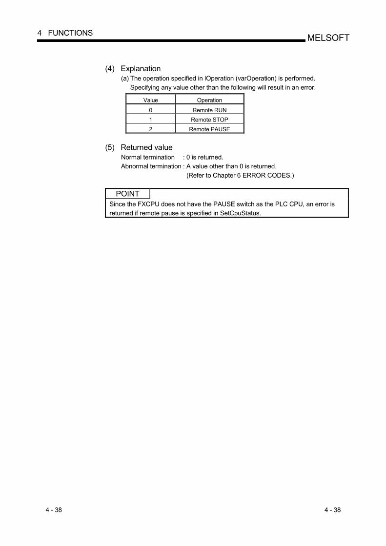
4 - 38 4 - 38
MELSOFT4 FUNCTIONS
(4) Explanation
(a) The operation specified in lOperation (varOperation) is performed. Specifying any value other than the following will result in an error.
Value Operation
0 Remote RUN 1 Remote STOP 2 Remote PAUSE
(5) Returned value
Normal termination : 0 is returned. Abnormal termination : A value other than 0 is returned.
(Refer to Chapter 6 ERROR CODES.)
POINT Since the FXCPU does not have the PAUSE switch as the PLC CPU, an error is returned if remote pause is specified in SetCpuStatus.

4 - 39 4 - 39
MELSOFT4 FUNCTIONS
4.2.15 EntryDeviceStatus (Device status monitor registration)
(1) Applicable ACT controls This function is available for all ACT controls but the ActSupoort and ActMLSupport controls.
(2) Feature
Registers devices whose statuses will be monitored. (3) Format
Visual Basic R 6.0, VBA : lRet = object.EntryDeviceStatus(szDeviceList, lSize, lMonitorCycle, lData(0))
Long lRet Returned value Output String szDeviceList Registered device name list Input Long lSize Number of registered device points Input Long lMonitorCycle Status monitor time interval Input Long lData(n) Registered device value list Input
Visual C++ R 6.0, Visual C++ R .NET(MFC) : lRet = object.EntryDeviceStatus
(szDeviceList, lSize, lMonitorCycle, lplData)
Long lRet Returned value Output CString szDeviceList Registered device name list Input Long lSize Number of registered device points Input Long lMonitorCycle Status monitor time interval Input Long lplData Registered device value list Input
VBScript: varRet = object.EntryDeviceStatus(varDeviceList, varSize,
varMonitorCycle, varData) VARIANT varRet Returned value(LONG type) Output VARIANT varDeviceList Registered device name list
(BSTR type) Input
VARIANT varSize Number of registered device points (LONG type)
Input
VARIANT varMonitorCycle Status monitor time interval (LONG type)
Input
VARIANT varData Registered device value list (LONG type)
Input
Visual Basic R .NET : IRet = object.EntryDeviceStatus(szDeviceList, ISize,
IMonitorCycle, IData(0)) Integer IRet Returned value Output String szDeviceList Registered device name list Input Integer ISize Number of registered device points Input Integer IMonitorCycle Status moniter time interval Input Integer IData(n) Registered device value list Input
Visual C++ R .NET : iRet = object.EntryDeviceStatus(szDeviceList, iSize,
iMonitorCycle, iplData) int iRet Returned value Output String szDeviceList Registered device name list Input int iSize Number of registered device points Input int iMonitorCycle Status moniter time interval Input int iplData Registered device value list Input

4 - 40 4 - 40
MELSOFT4 FUNCTIONS
(4) Explanation
(a) Check whether lSize (varSize) of the device group specified in szDeviceList (varDeviceList) is in the status specified in lData (lplData or varData). Specify the check time in lMonitorCycle (varMonitorCycle). When the status is established, the OnDeviceStatus function of the user application is executed.
(b) Using the line feed symbol, separate the devices in the character string specified in the device list. The last device need not be followed by the line feed symbol. (Example) Visual Basic R , VBA, VBScript : "D0" & vbLf & "D1" & vbLf & "D2" Visual C++ R : D0\nD1\nD2
(c) The maximum number of device points that may be specified in lSize (varSize) is 20 points.
(d) In lMonitorCycle (varMonitorCycle), specify a value within the range 1 second to 1 hour (set between 1 to 3600 in seconds). Specifying any other value outside the above range will result in an error.
(e) Store the registered device value list in lData (lplData or varData).
(5) Device specifying methods Specify the devices in the following methods. (Example 1) When devices are specified as follows (3 points)
When using Visual Basic R , VBA, VBScript : M0 & vbLf & D0 & vbLf & K8M0 When using Visual C++ R : M0\nD0\nK8M0
2 Upper Bytes 2 Lower Bytes 1 M0 1 D0
M16 to M31 2 M0 to M15 2 (Example 2) When devices including CN200 and later of FXCPU are specified
(3 points in all) 3 When using Visual Basic R , VBA, VBScript : D0 & vbLf & CN200 & vbLf & D1 When using Visual C++ R : D0\nCN200\nD1
2 Upper Bytes 2 Lower Bytes 1 D0
H of CN200 L of CN200 1 D1
(Example 3) When devices including FD are specified (3 points in all) When using Visual Basic R , VBA, VBScript : D0 & vbLf & FD0 & vbLf & D1 When using Visual C++ R : D0\nFD0\nD1
2 Upper Bytes 2 Lower Bytes 1 D0 1 LL of FD0 1 D1
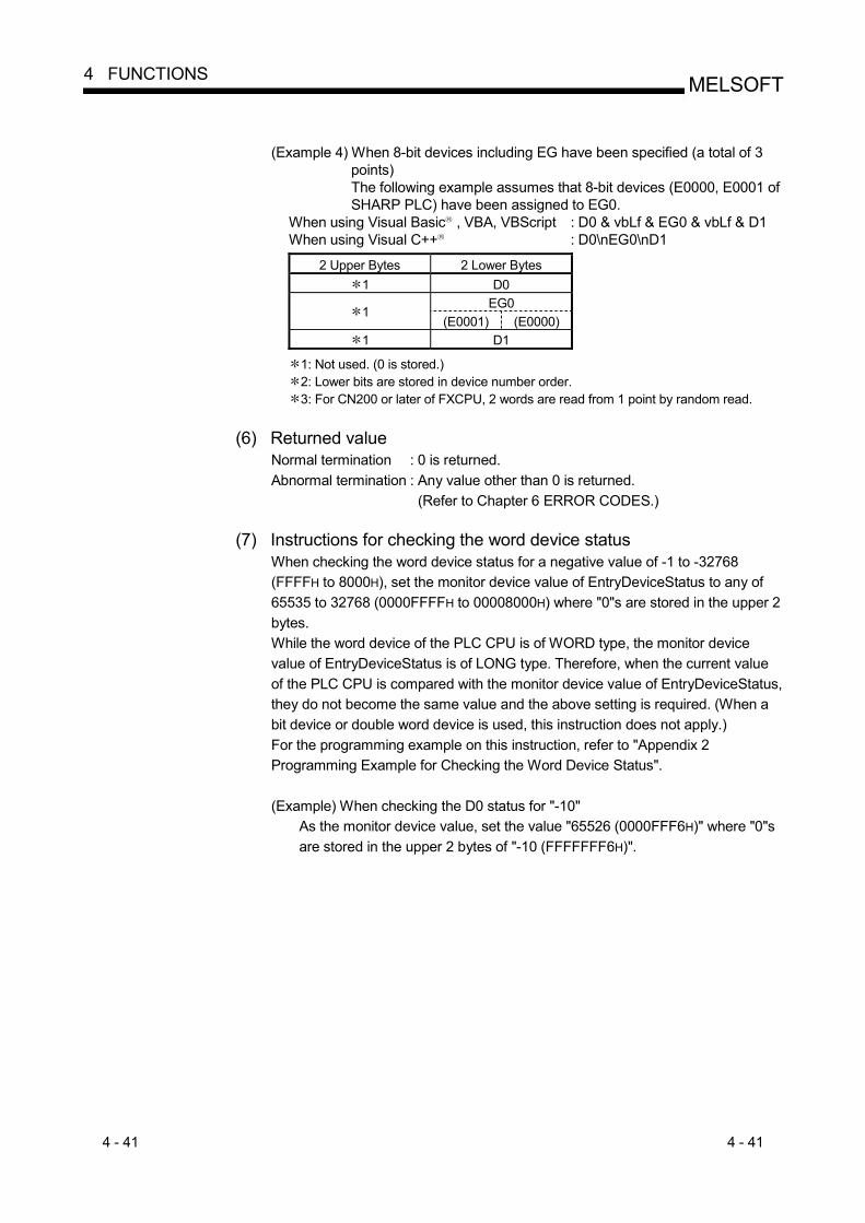
4 - 41 4 - 41
MELSOFT4 FUNCTIONS
(Example 4) When 8-bit devices including EG have been specified (a total of 3
points) The following example assumes that 8-bit devices (E0000, E0001 of SHARP PLC) have been assigned to EG0.
When using Visual Basic R , VBA, VBScript : D0 & vbLf & EG0 & vbLf & D1 When using Visual C++ R : D0\nEG0\nD1
2 Upper Bytes 2 Lower Bytes 1 D0
EG0 1
(E0001) (E0000) 1 D1
1: Not used. (0 is stored.) 2: Lower bits are stored in device number order. 3: For CN200 or later of FXCPU, 2 words are read from 1 point by random read.
(6) Returned value
Normal termination : 0 is returned. Abnormal termination : Any value other than 0 is returned.
(Refer to Chapter 6 ERROR CODES.)
(7) Instructions for checking the word device status When checking the word device status for a negative value of -1 to -32768 (FFFFH to 8000H), set the monitor device value of EntryDeviceStatus to any of 65535 to 32768 (0000FFFFH to 00008000H) where "0"s are stored in the upper 2 bytes. While the word device of the PLC CPU is of WORD type, the monitor device value of EntryDeviceStatus is of LONG type. Therefore, when the current value of the PLC CPU is compared with the monitor device value of EntryDeviceStatus, they do not become the same value and the above setting is required. (When a bit device or double word device is used, this instruction does not apply.) For the programming example on this instruction, refer to "Appendix 2 Programming Example for Checking the Word Device Status". (Example) When checking the D0 status for "-10"
As the monitor device value, set the value "65526 (0000FFF6H)" where "0"s are stored in the upper 2 bytes of "-10 (FFFFFFF6H)".
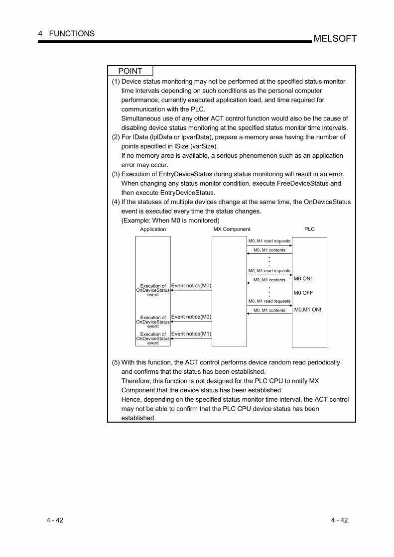
4 - 42 4 - 42
MELSOFT4 FUNCTIONS
POINT
(1) Device status monitoring may not be performed at the specified status monitor time intervals depending on such conditions as the personal computer performance, currently executed application load, and time required for communication with the PLC. Simultaneous use of any other ACT control function would also be the cause of disabling device status monitoring at the specified status monitor time intervals.
(2) For lData (lplData or lpvarData), prepare a memory area having the number of points specified in lSize (varSize). If no memory area is available, a serious phenomenon such as an application error may occur.
(3) Execution of EntryDeviceStatus during status monitoring will result in an error. When changing any status monitor condition, execute FreeDeviceStatus and then execute EntryDeviceStatus.
(4) If the statuses of multiple devices change at the same time, the OnDeviceStatus event is executed every time the status changes. (Example: When M0 is monitored)
MX Component
M0 ON!
M0,M1 ON!
M0 OFF
Application PLC
Execution ofOnDeviceStatus
event
Execution ofOnDeviceStatus
event
Execution ofOnDeviceStatus
event
Event notice(M0)
Event notice(M0)
Event notice(M1)
M0, M1 read requests
M0, M1 contents
M0, M1 read requests
M0, M1 contents
M0, M1 read requests
M0, M1 contents
(5) With this function, the ACT control performs device random read periodically
and confirms that the status has been established. Therefore, this function is not designed for the PLC CPU to notify MX Component that the device status has been established. Hence, depending on the specified status monitor time interval, the ACT control may not be able to confirm that the PLC CPU device status has been established.

4 - 43 4 - 43
MELSOFT4 FUNCTIONS
4.2.16 FreeDeviceStatus (Device status monitor deregistration)
(1) Applicable ACT controls This function is available for all ACT controls but the ActSupoort and ActMLSupport controls.
(2) Feature
Deregisters the devices that have been registered in EntryDeviceStatus to monitor statuses.
(3) Format
Visual Basic R 6.0, Visual C++ R 6.0, Visual C++ R .NET(MFC), VBA : lRet = object.FreeDeviceStatus()
Long lRet Returned value Output
VBScript : varRet = object.FreeDeviceStatus() VARIANT varRet Returned value (LONG type) Output
Visual Basic R .NET : IRet = object.FreeDeviceStatus()
Integer IRet Returned value Output
Visual C++ R .NET : iRet = object. FreeDeviceStatus() int iRet Returned value Output
(4) Explanation
The devices that have been set by the EntryDeviceStatus function to monitor statuses are deregistered.
(5) Returned value
Normal termination : 0 is returned. Abnormal termination : Any value other than 0 is returned.
(Refer to Chapter 6 ERROR CODES.)

4 - 44 4 - 44
MELSOFT4 FUNCTIONS
4.2.17 OnDeviceStatus (Announces event)
(1) Applicable ACT controls This function is available for all ACT controls but the ActSupoort and ActMLSupport controls.
(2) Feature
Gives event notice when the device condition registered with the EntryDeviceStatus function holds.
(3) Format
Visual Basic R 6.0,VBA : object.OnDeviceStatus(szDevice, lData, lReturnCode) String szDevice Name of device whose condition
has held Input
Long lData Value of device whose condition has held
Input
Long lReturnCode Returned value of condition check processing
Input
Visual C++ R 6.0, Visual C++ R .NET(MFC) : object.OnDeviceStatus( szDevice, lData, lReturnCode)
LPCTSTR szDevice Name of device whose condition has held
Input
Long lData Value of device whose condition has held
Input
Long lReturnCode Returned value of condition check processing
Input
VBScript : object.OnDeviceStatus(varDevice, varData, varReturnCode) VARIANT varDevice Name of device whose condition
has held(BSTR type) Input
VARIANT varData Value of device whose condition has held(LONG type)
Input
VARIANT varReturnCode Returned value of condition check processing(LONG type)
Input
Visual Basic R .NET : Private Sub AxActEasyIF1_OnDeviceStatus(ByVal sender As System.Object, ByVal e As AxACTMULTILib. _IActEasyIFEvents_OnDeviceStatusEvent)
ByVal sender As System.Object Event occurrence source Input ByVal e As AxACTMULTILib._IActEasyIFEvents_OnDeviceStatusEvent
OnDeviceStatus Event data Input The data e members of the OnDeviceStatus event are as follows.
e.szDevice Name of device whose condition has held e.lReturnCode Value of device whose condition has held e.lData Returned value of condition check processing
Visual C++ R .NET : private: System::Void axActEasyIF1_OnDeviceStatus (System::Object sender, AxInterop::ACTMULTILib:: _IActEasyIFEvents_OnDeviceStatusEvent e)
System::Object sender Event occurrence source Input AxInterop::ACTMULTILib::_IActEasyIFEvents_OnDeviceStatusEvent e
OnDeviceStatus Event data Input The data e members of the OnDeviceStatus event are as follows.
e->szDevice Name of device whose condition has held e->lReturnCode Value of device whose condition has held e->lData Returned value of condition check processing

4 - 45 4 - 45
MELSOFT4 FUNCTIONS
(4) Explanation
(a) The application is notified of an event when the device condition registered with the EntryDeviceStatus function holds. Placing this function in the user application allows the application to receive the event when the registered device condition holds.
(b) The device value registered to EntryDeviceStatus enters lData (varData). (Example) When the word device is checked for the value "-1"
Set 65535 (0000FFFFH) in EntryDeviceStatus as a registered device value. When the value of the target word device of the PLC CPU becomes "-1 (FFFFH), OnDeviceStatus is executed and (0000FFFFH) enters lData (varData).
(5) Returned value
None
POINT • When the following setting has been made in the user application, the event of
OnDeviceStatus does not occur if the condition of the device registered to the EntryDeviceStatus function is established. Note that when the user application is put in an event occurrence waiting state, control will not return to the ACT control and device management processing will stop until the following setting is terminated. (1) User application created using Visual Basic R or VBA (Excel)
(a) The message box is displayed in the user application. (b) The InputBox/OutputBox is displayed in the user application.
(2) User application created using Visual Basic R , Visual C++ R , VBA (Excel Access) or VBScript (a) The Sleep processing, WaitForSingleObject function, or similar standby
function is used in the user application. • For how to install Reference, refer to the sample programs for Reference of
VB .NET/VC .NET (Section 5.6, Section 5.7).

4 - 46 4 - 46
MELSOFT4 FUNCTIONS
4.2.18 ReadDeviceBlock2 (Device batch-read)
(1) Applicable ACT controls This function is available for all ACT controls but the ActSupoort and ActMLSupport controls.
(2) Feature
Batch-reads 2-byte data from devices. (3) Format
Visual Basic R 6.0, VBA : lRet = object.ReadDeviceBlock2(szDevice, lSize, iData(0))
Long lRet Returned value Output String szDevice Device name Input Long lSize Number of read points Input Integer iData(n) Read device values Output
Visual C++ R 6.0, Visual C++ R .NET(MFC) : lRet = object.ReadDeviceBlock2
(szDevice, lSize, lpsData) Long lRet Returned value Output CString szDevice Device name Input Long lSize Number of read points Input Short lpsData Read device values Output
VBScript : varRet = object.ReadDeviceBlock2(varDevice, varSize, lpvarData)
VARIANT varRet Returned value (LONG type) Output VARIANT varDevice Device name(character string type) Input VARIANT varSize Number of read points(LONG type) Input VARIANT lpvarData Read device values (SHORT type) Output
Visual Basic R .NET : IRet = object.ReadDeviceBlock2(szDevice, ISize, sData(0))
Integer IRet Returned value Output String szDevice Device name Input Integer ISize Number of read points Input short sData(n) Read device values Output
Visual C++ R .NET : iRet = object.ReadDeviceBlock2( szDevice, iSize,
lpsData) int iRet Returned value Output String szDevice Device name Input int iSize Number of read points Input short lpsData Read device values Output
(4) Explanation
(a) Batch-reads lSize (varSize) of device values as SHORT type data from the devices, starting from the one specified in szDevice (varDevice).
(b) The read device values are stored in iData (lpsData or lpvarData). (c) Reserve an array of lSize (varSize) or more for iData (lpsData or lpvarData).

4 - 47 4 - 47
MELSOFT4 FUNCTIONS
(5) Device specifying methods
Specify the devices in the following methods. <When bit device is specified> <When word device is specified> (Example) Data are read from 3 points
(3 words) on a 16 point basis, starting from M0.
(Example) 3 points from D0
2 Bytes 2 Bytes M0 to M15 1 D0 M16 to M31 1 D1 M32 to M47 1 D2
<When CN200 and later of FXCPU are specified>
<When FD device is specified (4-word device)>
(Example) 6 points from CN200 2: (Example) 6 points from FD0 2 Bytes 2 Bytes
L of CN200 (2 Lower Bytes) LL of FD0 H of CN200 (2 Upper Bytes) LH of FD0 L of CN201 (2 Lower Bytes) HL of FD0 H of CN201(2 Upper Bytes) HH of FD0 L of CN202 (2 Lower Bytes) LL of FD1 H of CN202(2 Upper Bytes) LH of FD1
<8-bit devices assigned to gateway devices>
(Example) When 8-bit devices (E0000 to E0007 of SHARP PLC) have been assigned to 4 points, starting from EG0 (EG0 - EG3).
2 Bytes EG0
(E0001) (E0000) EG1
(E0003) (E0002) EG2
(E0005) (E0004) EG3
(E0007) (E0006) 1: Lower bits are stored in device number order. 2: For CN200 or later of FXCPU, 2 words are read from 2 points. Read from 1 point will result in an error.
(6) Returned value
Normal termination : 0 is returned. Abnormal termination : Any value other than 0 is returned.
(Refer to Chapter 6 ERROR CODES.)
POINT (1) The maximum number of read points that may be specified in lSize(varSize)
should satisfy the following range. Read starting device number + number of read points last device number
(2) When the bit device is specified, a multiple of 16 may be specified as the device number.
(3) For iData (lpsData or lpvarData), prepare a memory area having the number of points specified in lSize (varSize). If there is no memory area, a critical phenomenon such as an application error may occur.
4 - 48 4 - 48
MELSOFT4 FUNCTIONS
4.2.19 WriteDeviceBlock2 (Device batch-write)
(1) Applicable ACT controls This function is available for all ACT controls but the ActSupoort and ActMLSupport controls.
(2) Feature
Batch-writes 2-byte data to devices. (3) Format
Visual Basic R 6.0, VBA : lRet = object.WriteDeviceBlock2(szDevice, lSize, iData(0))
Long lRet Returned value Output String szDevice Device name Input Long lSize Number of write points Input Integer iData(n) Device values to be written Input
Visual C++ R 6.0, Visual C++ R .NET(MFC) : lRet = object.WriteDeviceBlock2
(szDevice, lSize, lpsData) Long lRet Returned value Output CString szDevice Device name Input Long lSize Number of write points Input Short lpsData Device values to be written Input
VBScript : varRet = object.WriteDeviceBlock2(varDevice, varSize, varData)
VARIANT varRet Returned value(LONG type) Output VARIANT varDevice Device name(character string type) Input VARIANT varSize Number of write points(LONG type) Input VARIANT varData Device values to be written (SHORT type) Input
Visual Basic R .NET : IRet = object.WriteDeviceBlock2(szDevice, ISize, sData(0))
Integer IRet Returned value Output String szDevice Device name Input Integer ISize Number of write points Input short sData(n) Device values to be written Input
Visual C++ R .NET : iRet = object.WriteDeviceBlock2( szDevice, iSize,
lpsData) int iRet Returned value Output String szDevice Device name Input int iSize Number of write points Input short lpsData Device values to be written Input
(4) Explanation
(a) Batch-writes lSize (varSize) of device values to the devices, starting from the one specified in szDevice (varDevice).
(b) Store the device values to be written in iData (lpsData or varData). (c) Reserve an array of lSize (varSize) or more for iData (lpsData or varData).

4 - 49 4 - 49
MELSOFT4 FUNCTIONS
(5) Device specifying methods
Specify the devices in the following methods. <When bit device is specified> <When word device is specified> (Example) Data are written to 3 points
(3 words) on a 16 point basis, starting from M0.
(Example) 3 points from D0
2 Bytes 2 Bytes M0 to M15 1 D0 M16 to M31 1 D1 M32 to M47 1 D2
<When CN200 and later of FXCPU are specified>
<When FD device is specified (4-word device)>
(Example) 6 points from CN200 2 (Example) 6 points from FD0 2 Bytes 2 Bytes
L of CN200 (2 Lower Bytes) LL of FD0 H of CN200 (2 Upper Bytes) LH of FD0 L of CN201 (2 Lower Bytes) HL of FD0 H of CN201(2 Upper Bytes) HH of FD0 L of CN202 (2 Lower Bytes) LL of FD1 H of CN202(2 Upper Bytes) LH of FD1
<8-bit devices assigned to gateway devices>
(Example) When 8-bit devices (E0000 to E0007 of SHARP PLC) have been assigned to 4 points, starting from EG0 (EG0 - EG3).
2 Bytes EG0
(E0001) (E0000) EG1
(E0003) (E0002) EG2
(E0005) (E0004) EG3
(E0007) (E0006) 1: Lower bits are stored in device number order. 2: For CN200 or later of FXCPU, 2 words are written from 2 points. Write from 1 point will result in an error.
(6) Returned value
Normal termination : 0 is returned. Abnormal termination : Any value other than 0 is returned.
(Refer to Chapter 6 ERROR CODES.)
POINT (1) The maximum number of write points that may be specified in lSize(varSize)
should satisfy the following range. Write starting device number + number of write points last device number
(2) When the bit device is specified, a multiple of 16 may be specified as the device number.
(3) For iData (lpsData or varData), prepare a memory area having the number of points specified in lSize (varSize). If there is no memory area, a critical phenomenon such as an application error may occur.
4 - 50 4 - 50
MELSOFT4 FUNCTIONS
4.2.20 ReadDeviceRandom2 (Device random-read)
(1) Applicable ACT controls This function is available for all ACT controls but the ActSupoort and ActMLSupport controls.
(2) Feature
Randomly reads 2-byte data from devices.
(3) Format Visual Basic R 6.0, VBA : lRet = object.ReadDeviceRandom2(szDeviceList, lSize,
iData(0)) Long lRet Returned value Output String szDeviceList Device name Input Long lSize Number of read points Input Integer iData(n) Read device values Output
Visual C++ R 6.0, Visual C++ R .NET(MFC) : lRet = object.ReadDeviceRandom2
(szDeviceList, lSize, lpsData) Long lRet Returned value Output CString szDeviceList Device name Input Long lSize Number of read points Input Short lpsData Read device values Output
VBScript : varRet = object.ReadDeviceRandom2(varDeviceList, varSize,
lpvarData) VARIANT varRet Returned value(LONG type) Output VARIANT varDeviceList Device name(character string type) Input VARIANT varSize Number of read points(LONG type) Input VARIANT lpvarData Read device values (SHORT type) Output
Visual Basic R .NET : IRet = object.ReadDeviceRandom2(szDeviceList, ISize,
sData(0)) Integer IRet Returned value Output String szDeviceList Device name Input Integer ISize Number of read points Input short sData(n) Read device values Output
Visual C++ R .NET : iRet = object.ReadDeviceRandom2( szDeviceList, iSize,
lpsData) int iRet Returned value Output String szDeviceList Device name Input int iSize Number of read points Input short lpsData Read device values Output
(4) Explanation
(a) Randomly reads only lSize (varSize) of device values from the device group specified in szDeviceList (varDeviceList).
(b) The read device values are stored in iData (lpsData or lpvarData). (c) Using the line feed symbol, separate the devices in the character string
specified in the device list. The last device need not be followed by the line feed symbol. (Example) Visual Basic R , VBA, VBScript : "D0" & vbLf & "D1" & vbLf & "D2" Visual C++ R : D0\nD1\nD2
(d) Reserve an array of lSize (varSize) or more for iData (lpsData or lpvarData).

4 - 51 4 - 51
MELSOFT4 FUNCTIONS
(5) Device specifying methods
Specify the devices in the following methods.
(Example 1) When devices are specified as follows (3 points) When using Visual Basic R , VBA, VBScript : M0 & vbLf & D0 & vbLf & K8M0 When using Visual C++ R : M0\nD0\nK8M0
2 Bytes
M0 1 D0
M0 to M15 2 (Example 2) When devices including CN200 and later of FXCPU are specified
(3 points in all) 3 When using Visual Basic R , VBA, VBScript : D0 & vbLf & CN200 & vbLf & D1 When using Visual C++ R : D0\nCN200\nD1
2 Bytes
D0 L of CN200 (2 Lower Bytes)
D1 (Example 3) When devices including FD are specified (3 points in all)
When using Visual Basic R , VBA, VBScript : D0 & vbLf & FD0 & vbLf & D1 When using Visual C++ R : D0\nFD0\nD1
2 Bytes
D0 LL of FD0 (2 Lower Bytes)
D1 (Example4) When 8-bit devices including EG have been specified
(a total of 3 points) The following example assumes that 8-bit devices (E0000, E0001 of SHARP PLC) have been assigned to EG0.
When using Visual Basic R , VBA, VBScript : D0 & vbLf & EG0 & vbLf & D1 When using Visual C++ R : D0\nEG0\nD1
2 Bytes
D0 EG0
(E0001) (E0000)
D1 1: The device from where data will be read is only one point of "M0", and "0" or "1" is
stored as the device value. 2: Lower bits are stored in device number order.
Data are not read from the upper 2 bytes, M16 to M31. 3: For CN200 and later of the FXCPU, specifying 1 point for ReadDeviceRandom2
reads data from the L (lower 2 bytes) of the specified device. Data are not read from the H (upper 2 bytes) of the specified device.

4 - 52 4 - 52
MELSOFT4 FUNCTIONS
(6) Returned value
Normal termination : 0 is returned. Abnormal termination : Any value other than 0 is returned.
(Refer to Chapter 6 ERROR CODES.)
POINT (1) The maximum number of read points that may be specified in lSize(varSize) is
up to 0x7FFFFFFF points. (2) For iData(lpsData or lpvarData), prepare a memory area having the number of
points specified in lSize(varSize). If there is no memory area, a critical phenomenon such as an application error may occur.
(3) When a double word device is specified, only the data of the lower 1 word (2 bytes) are stored in ReadDeviceRandom2. (An error will not occur.) When reading data from a double word device, use ReadDeviceRandom or GetDevice.

4 - 53 4 - 53
MELSOFT4 FUNCTIONS
4.2.21 WriteDeviceRandom2 (Device random-write)
(1) Applicable ACT controls This function is available for all ACT controls but the ActSupoort and ActMLSupport controls.
(2) Feature
Randomly writes 2-byte data to devices.
(3) Format Visual Basic R 6.0, VBA : lRet = object.WriteDeviceRandom2(szDeviceList, lSize,
iData(0)) Long lRet Returned value Output String szDeviceList Device name Input Long lSize Number of write points Input Integer iData(n) Device values to be written Input
Visual C++ R 6.0, Visual C++ R .NET(MFC) : lRet = object.WriteDeviceRandom2
(szDeviceList, lSize, lpsData) Long lRet Returned value Output CString szDeviceList Device name Input Long lSize Number of write points Input Short lpsData Device values to be written Input
VBScript : varRet = object.WriteDeviceRandom2(varDeviceList, varSize,
varData) VARIANT varRet Returned value (LONG type) Output VARIANT varDeviceList Device name (character string type) Input VARIANT varSize Number of write points (LONG type) Input VARIANT varData Device values to be written (SHORT type) Input
Visual Basic R .NET : IRet = object.WriteDeviceRandom2(szDeviceList, ISize,
sData(0)) Integer IRet Returned value Output String szDeviceList Device name Input Integer ISize Number of write points Input short sData(n) Device values to be written Input
Visual C++ R .NET : iRet = object.WriteDeviceRandom2( szDeviceList, iSize,
lpsData) int iRet Returned value Output String szDseviceList Device name Input int iSize Number of write points Input short lpsData Device values to be written Input
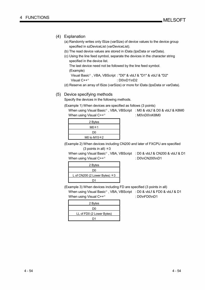
4 - 54 4 - 54
MELSOFT4 FUNCTIONS
(4) Explanation
(a) Randomly writes only lSize (varSize) of device values to the device group specified in szDeviceList (varDeviceList).
(b) The read device values are stored in iData (lpsData or varData). (c) Using the line feed symbol, separate the devices in the character string
specified in the device list. The last device need not be followed by the line feed symbol. (Example) Visual Basic R , VBA, VBScript : "D0" & vbLf & "D1" & vbLf & "D2" Visual C++ R : D0\nD1\nD2
(d) Reserve an array of lSize (varSize) or more for iData (lpsData or varData).
(5) Device specifying methods Specify the devices in the following methods. (Example 1) When devices are specified as follows (3 points)
When using Visual Basic R , VBA, VBScript : M0 & vbLf & D0 & vbLf & K8M0 When using Visual C++ R : M0\nD0\nK8M0
2 Bytes
M0 1 D0
M0 to M15 2 (Example 2) When devices including CN200 and later of FXCPU are specified
(3 points in all) 3 When using Visual Basic R , VBA, VBScript : D0 & vbLf & CN200 & vbLf & D1 When using Visual C++ R : D0\nCN200\nD1
2 Bytes
D0 L of CN200 (2 Lower Bytes) 3
D1 (Example 3) When devices including FD are specified (3 points in all)
When using Visual Basic R , VBA, VBScript : D0 & vbLf & FD0 & vbLf & D1 When using Visual C++ R : D0\nFD0\nD1
2 Bytes
D0 LL of FD0 (2 Lower Bytes)
D1

4 - 55 4 - 55
MELSOFT4 FUNCTIONS
(Example4) When 8-bit devices including EG have been specified
(a total of 3 points) The following example assumes that 8-bit devices (E0000, E0001 of SHARP PLC) have been assigned to EG0.
When using Visual Basic R , VBA, VBScript : D0 & vbLf & EG0 & vbLf & D1 When using Visual C++ R : D0\nEG0\nD1
2 Bytes
D0 EG0
(E0001) (E0000)
D1 1: The device to where data will be written is only one point of "M0", and the lowest
bit of the set 2-byte data is written as the device value. 2: Lower bits are stored in device number order.
"0"s are written to the upper 2 bytes, M16 to M31. 3: For CN200 and later of the FXCPU, specifying 1 point for WriteDeviceRandom2
writes data to the L (lower 2 bytes) of the specified device. "0"s are written to the H (upper 2 bytes) of the specified device.
(6) Returned value
Normal termination : 0 is returned. Abnormal termination : Any value other than 0 is returned.
(Refer to Chapter 6 ERROR CODES.)
POINT (1) The maximum number of write points that may be specified in lSize(varSize) is
up to 0x7FFFFFFF points. (2) For iData(lpsData or varData), prepare a memory area having the number of
points specified in lSize(varSize). If there is no memory area, a critical phenomenon such as an application error may occur.
(3) When a double word device is specified, data are written to the data area of the lower 1 word (2 bytes) in WriteDeviceRandom2, and "0"s are written to the data area of the upper 1 word (2 bytes). When writing data to a double word device, use WriteDeviceRandom or SetDevice.
4 - 56 4 - 56
MELSOFT4 FUNCTIONS
4.2.22 SetDevice2 (Device data setting)
(1) Applicable ACT controls This function is available for all ACT controls but the ActSupoort and ActMLSupport controls.
(2) Feature
Sets 2-byte data to one device point.
(3) Format Visual Basic R 6.0, VBA : lRet = object.SetDevice2(szDevice, iData)
Long lRet Returned value Output String szDevice Device name Input Integer iData Set data Input
Visual C++ R 6.0, Visual C++ R .NET(MFC) : lRet = object.SetDevice2(szDevice,
sData) Long lRet Returned value Output CString szDevice Device name Input Short sData Set data Input
VBScript : varRet = object.SetDevice2(varDevice, varData)
VARIANT varRet Returned value (LONG type) Output VARIANT varDevice Device name
(character string type) Input
VARIANT varData Set data (SHORT type) Input
Visual Basic R .NET : IRet = object.SetDevice2(szDevice, sData) Integer IRet Returned value Output String szDevice Device name Input short sData Set data Input
Visual C++ R .NET : iRet = object.SetDevice2( szDevice, sData)
int iRet Returned value Output String szDevice Device name Input short sData Set data Input
(4) Explanation
(a) The operation specified in iData(sData or varData) is performed for one point of device specified in szDevice(varDevice).
(b) When the bit device is specified, the least significant bit of the iData value (sData value or varData value) becomes valid.
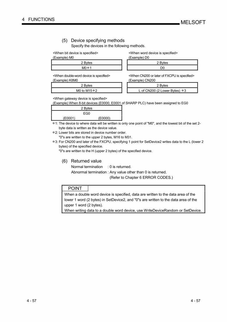
4 - 57 4 - 57
MELSOFT4 FUNCTIONS
(5) Device specifying methods
Specify the devices in the following methods.
<When bit device is specified> <When word device is specified> (Example) M0 (Example) D0
2 Bytes 2 Bytes M0 1 D0
<When double-word device is specified>
<When CN200 or later of FXCPU is specified>
(Example) K8M0 (Example) CN200 2 Bytes 2 Bytes
M0 to M15 2 L of CN200 (2 Lower Bytes) 3 <When gateway device is specified>
(Example) When 8-bit devices (E0000, E0001 of SHARP PLC) have been assigned to EG0 2 Bytes
EG0 (E0001) (E0000)
1: The device to where data will be written is only one point of "M0", and the lowest bit of the set 2-byte data is written as the device value.
2: Lower bits are stored in device number order. "0"s are written to the upper 2 bytes, M16 to M31.
3: For CN200 and later of the FXCPU, specifying 1 point for SetDevice2 writes data to the L (lower 2 bytes) of the specified device. "0"s are written to the H (upper 2 bytes) of the specified device.
(6) Returned value
Normal termination : 0 is returned. Abnormal termination : Any value other than 0 is returned.
(Refer to Chapter 6 ERROR CODES.)
POINT When a double word device is specified, data are written to the data area of the lower 1 word (2 bytes) in SetDevice2, and "0"s are written to the data area of the upper 1 word (2 bytes). When writing data to a double word device, use WriteDeviceRandom or SetDevice.

4 - 58 4 - 58
MELSOFT4 FUNCTIONS
4.2.23 GetDevice2 (Device data acquisition)
(1) Applicable ACT controls This function is available for all ACT controls but the ActSupoort and ActMLSupport controls.
(2) Feature
Gets 2-byte data from one device point.
(3) Format Visual Basic R 6.0, VBA : lRet = object.GetDevice2(szDevice, iData)
Long lRet Returned value Output String szDevice Device name Input Integer iData Acquired data Output
Visual C++ R 6.0, Visual C++ R .NET(MFC) : lRet = object.GetDevice2(szDevice,
lpsData) Long lRet Returned value Output CString szDevice Device name Input Short lpsData Acquired data Output
VBScript : varRet = object.GetDevice2(varDevice, lpvarData)
VARIANT varRet Returned value (LONG type) Output VARIANT varDevice Device name
(character string type) Input
VARIANT lpvarData Acquired data (SHORT type) Output
Visual Basic R .NET : IRet = object.GetDevice2(szDevice, sData) Integer IRet Returned value Output String szDevice Device name Input short sData Acquired data Output
Visual C++ R .NET : iRet = object.GetDevice2( szDevice, spsData)
int iRet Returned value Output String szDevice Device name Input short spsData Acquired data Output
(4) Explanation
(a) Stores the data of the one device point specified in szDevice (varDevice) into iData (lpsData or lpvarData).
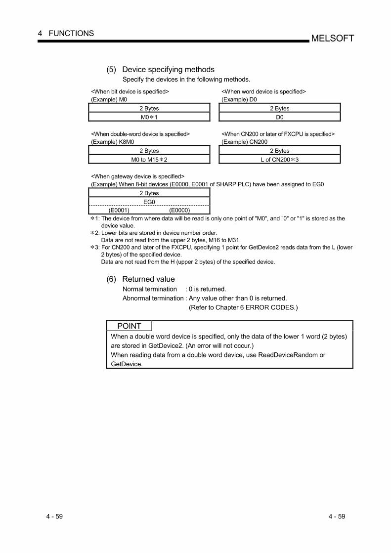
4 - 59 4 - 59
MELSOFT4 FUNCTIONS
(5) Device specifying methods
Specify the devices in the following methods.
<When bit device is specified> <When word device is specified> (Example) M0 (Example) D0
2 Bytes 2 Bytes M0 1 D0
<When double-word device is specified>
<When CN200 or later of FXCPU is specified>
(Example) K8M0 (Example) CN200 2 Bytes 2 Bytes
M0 to M15 2 L of CN200 3 <When gateway device is specified>
(Example) When 8-bit devices (E0000, E0001 of SHARP PLC) have been assigned to EG0 2 Bytes
EG0 (E0001) (E0000)
1: The device from where data will be read is only one point of "M0", and "0" or "1" is stored as the device value.
2: Lower bits are stored in device number order. Data are not read from the upper 2 bytes, M16 to M31.
3: For CN200 and later of the FXCPU, specifying 1 point for GetDevice2 reads data from the L (lower 2 bytes) of the specified device. Data are not read from the H (upper 2 bytes) of the specified device.
(6) Returned value
Normal termination : 0 is returned. Abnormal termination : Any value other than 0 is returned.
(Refer to Chapter 6 ERROR CODES.)
POINT When a double word device is specified, only the data of the lower 1 word (2 bytes) are stored in GetDevice2. (An error will not occur.) When reading data from a double word device, use ReadDeviceRandom or GetDevice.
4 - 60 4 - 60
MELSOFT4 FUNCTIONS
4.2.24 Connect (Telephone line connection)
(1) Applicable ACT controls This function is available for the ActEasyIF, ActA6TEL, ActQ6TEL, ActFXCPUTEL, ActAJ71QC24TEL and ActQJ71C24TEL controls.
(2) Feature
Connects the telephone line.
(3) Format Visual Basic R 6.0, Visual C++ R 6.0, Visual C++ R .NET(MFC), VBA : lRet = object.Connect()
Long lRet Returned value Output
Visual Basic R .NET : IRet = object.Connect() Integer IRet Returned value Output
Visual C++ R .NET : iRet = object.Connect()
int iRet Returned value Output
(4) Explanation (a) Connects the telephone line on the basis of the property settings of the
modem communication control. (b) For the ActQJ71C24TEL control, the telephone line is connected in the
connection system that has been set in the ActConnectWay property. When Auto line connect (callback number specification), callback connect (number specification) or callback request (number specification) has been set in the ActConnectWay property, an error will occur if a number is not set in the ActCallbackNumber property.
(5) Returned value
Normal termination : 0 is returned. Abnormal termination : Any value other than 0 is returned.
(Refer to Chapter 6 ERROR CODES.)
(6) Instructions for execution of Connect (a) Always connect the telephone line before execution of Open. (b) When disconnecting the telephone line, execute Disconnect.
During Connect, the telephone line remains connected if Open and Close are repeated many times.
(c) If the telephone line is disconnected in the Open status for some reason, always execute Close before reconnecting the telephone line.

4 - 61 4 - 61
MELSOFT4 FUNCTIONS
(7) Instructions for use of multiple telephone line connection objects
(a) When the control types, port numbers and telephone numbers of the controls are different When the control types, port numbers and telephone numbers set to multiple controls differ from each other, an error (error code: 0xF1000016) will occur if Connect is executed by the control with port number and telephone number different from those of the control that executed Connect first.
(b) When the port numbers and telephone numbers of the controls are the same
When the control types, port numbers and telephone numbers set to multiple controls are the same, the termination status changes depending on the connection system of the callback function. The following table indicates the relations between the callback function connection system and the termination status.
Connection System of Control That Executes Connect Second or Later
Connection System of Control That has Executed Connect First
Auto line connect Auto line connect (Callback fixation) Auto line connect (Callback number specification)
Callback connect (Fixation) Callback connect (Number specification)
Callback request (Fixation) Callback request (Number specification)
Callback reception waiting
Auto line connect Auto line connect (Callback fixation) Auto line connect (Callback number specification)
Callback connect (Fixation) Callback connect (Number specification)
Callback request (Fixation) Callback request (Number specification)
Callback reception waiting
: Normal termination : Abnormal termination (Error occurrence)

4 - 62 4 - 62
MELSOFT4 FUNCTIONS
4.2.25 Disconnect (Disconnects telephone line)
(1) Applicable ACT controls This function is available for the ActEasyIF, ActA6TEL, ActQ6TEL, ActFXCPUTEL, ActAJ71QC24TEL and ActQJ71C24TEL controls.
(2) Feature
Disconnects the telephone line.
(3) Format Visual Basic R 6.0, Visual C++ R 6.0, Visual C++ R .NET(MFC), VBA : lRet = object.Disconnect()
Long lRet Returned value Output
Visual Basic R .NET : IRet = object.Disconnect() Integer IRet Returned value Output
Visual C++ R .NET : iRet = object.Disconnect()
int iRet Returned value Output
(4) Explanation (a) Disconnects the telephone line that was connected using the Connect
function.
(5) Returned value Normal termination : 0 is returned. Abnormal termination : Any value other than 0 is returned.
(Refer to Chapter 6 ERROR CODES.)

4 - 63 4 - 63
MELSOFT4 FUNCTIONS
(6) Instructions for Disconnect execution
(a) When executing Disconnect during Open, execute Close before executing Disconnect.
(b) If the telephone line is disconnected in the Open status for some reason, always execute Close before reconnecting the telephone line.
(c) When multiple telephone line connection objects are used, Disconnect should be executed by the object that executed Connect first after another object has executed Disconnect. When multiple telephone line connection objects are used, the telephone line is not disconnected if the object that executed Connect first does not execute Disconnect. The following example gives how to use multiple objects together.
<Object A>
Connection start
End
Execution of Connect
Execution of Open
Execution of ReadDeviceBlock or like
Execution of Close
*1 : The actual telephone line is disconnected. Disconnect of the object A does not terminate normally until after Disconnect of the object B is executed.
<Object B>
Connection start
End
Execution of Connect
Execution of Open
Execution of ReadDeviceBlock or like
Execution of Close
Execution of Disconnect
Tele
phon
e lin
e be
ing
conn
ecte
d
Execution of Disconnect *1
<Example> When using two controls together (Including the case where the objects A and B are operated by different applications)
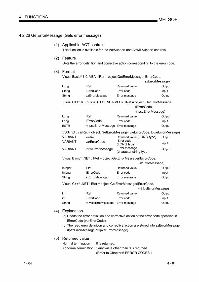
4 - 64 4 - 64
MELSOFT4 FUNCTIONS
4.2.26 GetErrorMessage (Gets error message)
(1) Applicable ACT controls This function is available for the ActSupport and ActMLSupport controls.
(2) Feature
Gets the error definition and corrective action corresponding to the error code.
(3) Format Visual Basic R 6.0, VBA : lRet = object.GetErrorMessage(lErrorCode,
szErrorMessage) Long lRet Returned value Output String lErrorCode Error code Input String szErrorMessage Error message Output
Visual C++ R 6.0, Visual C++ R .NET(MFC) : lRet = object. GetErrorMessage
(lErrorCode, lpszErrorMessage)
Long lRet Returned value Output Long lErrorCode Error code Input BSTR lpszErrorMessage Error message Output
VBScript : varRet = object. GetErrorMessage (varErrorCode, lpvarErrorMessage) VARIANT varRet Returned value (LONG type) Output VARIANT varErrorCode Error code
(LONG type) Input
VARIANT lpvarErrorMessage Error message (character string type)
Output
Visual Basic R .NET : IRet = object.GetErrorMessage(IErrorCode, szErrorMessage)
Integer IRet Returned value Output Integer IErrorCode Error code Input String szErrorMessage Error message Output
Visual C++ R .NET : iRet = object.GetErrorMessage(iErrorCode,
lpsErrorMessage) int iRet Returned value Output int iErrorCode Error code Input String lpsErrorMessage Error message Output
(4) Explanation
(a) Reads the error definition and corrective action of the error code specified in lErrorCode (varErrorCode).
(b) The read error definition and corrective action are stored into szErrorMessage (lpszErrorMessage or lpvarErrorMessage).
(5) Returned value
Normal termination : 0 is returned. Abnormal termination : Any value other than 0 is returned.
(Refer to Chapter 6 ERROR CODES.)

4 - 65 4 - 65
MELSOFT4 FUNCTIONS
4.3 Details of the Functions (Custom Interface)
This section explains the details of the functions. The details of the functions in this section assume that the custom interface is used. The custom interface may be used on only Visual C++ R . For the dispatch interface, refer to "Section 4.2 Details of the Functions (Dispatch Interface)". This section describes only the formats of the functions. For details of other than the formats, refer to "Section 4.2 Details of the Functions (Dispatch Interface)".
4.3.1 Open (Communication line opening)
hResult = object.Open( lplRetCode ) HRESULT hResult Returned value of COM Output LONG lplRetCode Returned value of communication function Output
4.3.2 Close (Communication line closing)
hResult = object.Close( lplRetCode ) HRESULT hResult Returned value of COM Output LONG lplRetCode Returned value of communication function Output
4.3.3 ReadDeviceBlock (Device batch-read)
hResult = object.ReadDeviceBlock( szDevice, lSize, lplData, lplRetCode ) HRESULT hResult Returned value of COM Output BSTR szDevice Device name Input LONG lSize Number of read points Input LONG lplData Read device values Output LONG lplRetCode Returned value of communication function Output
4.3.4 WriteDeviceBlock (Device batch-write)
hResult = object.WriteDeviceBlock( szDevice, lSize, lplData, lplRetCode ) HRESULT hResult Returned value of COM Output BSTR szDevice Device name Input LONG lSize Number of write points Input LONG lplData Written device values Input LONG lplRetCode Returned value of communication
function Output

4 - 66 4 - 66
MELSOFT4 FUNCTIONS
4.3.5 ReadDeviceRandom (Device random-read)
hResult = object.ReadDeviceBlock(szDeviceList, lSize, lplData, lplRetCode ) HRESULT hResult Returned value of COM Output BSTR szDeviceList Device name Input LONG lSize Number of read points Input LONG lplData Read device values Output LONG lplRetCode Returned value of communication function Output
4.3.6 WriteDeviceRandom (Device random-write)
hResult = object.WriteDeviceRandom( szDeviceList, lSize, lplData, lplRetCode )
HRESULT hResult Returned value of COM Output BSTR szDeviceList Device name Input LONG lSize Number of write points Input LONG lplData Written device values Input LONG lplRetCode Returned value of communication function Output
4.3.7 SetDevice (Device data setting)
hResult = object.SetDevice( szDevice, lData, lplRetCode ) HRESULT hResult Returned value of COM Output BSTR szDevice Device name Input LONG lData Set data Input LONG lplRetCode Returned value of communication function Output
4.3.8 GetDevice (Device data acquisition)
hResult = object.GetDevice( szDevice, lplData, lplRetCode ) HRESULT hResult Returned value of COM Output BSTR szDevice Device name Input LONG lplData Set data Output LONG lplRetCode Returned value of communication function Output

4 - 67 4 - 67
MELSOFT4 FUNCTIONS
4.3.9 ReadBuffer (Buffer memory read)
hResult = object.ReadBuffer( lStartIO, lAddress, lReadSize, lpsData, lplRetCode )
HRESULT hResult Returned value of COM Output LONG lStartIO First I/O number of module from where
values will be read Input
LONG lAddress Buffer memory address Input LONG lReadSize Read size Input SHORT lpsData Values read from buffer memory Output LONG lplRetCode Returned value of communication function Output
4.3.10 WriteBuffer (Buffer memory write)
hResult = object.WriteBuffer( lStartIO, lAddress, lWriteSize, lpsData, lplRetCode )
HRESULT hResult Returned value of COM Output LONG lStartIO First I/O number of module to where
values will be written Input
LONG lAddress Buffer memory address Input LONG lWriteSize Write size Input SHORT lpsData Values written to buffer memory Input LONG lplRetCode Returned value of communication function Output
4.3.11 GetClockDSata (Clock data read)
hResult = object.GetClockData( lpsYear, lpsMonth, lpsDay, lpsDayOfWeek, lpsHour, lpsMinute, lpsSecond, lplRetCode )
HRESULT hResult Returned value of COM Output SHORT lpsYear Read year value Output SHORT lpsMonth Read month value Output SHORT lpsDay Read day value Output SHORT lpsDayOfWeek Read day-of-week value Output SHORT lpsHour Read hour value Output SHORT lpsMinute Read minute value Output SHORT lpsSecond Read second value Output LONG lplRetCode Returned value of communication function Output

4 - 68 4 - 68
MELSOFT4 FUNCTIONS
4.3.12 SetClockData (Clock data write)
hResult = object.SetClockData( sYear, sMonth, sDay, sDayOfWeek, sHour, sMinute, sSecond, lplRetCode )
HRESULT hResult Returned value of COM Output SHORT sYear Year value to be written Input SHORT sMonth Month value to be written Input SHORT sDay Day value to be written Input SHORT sDayOfWeek Day-of-week value to be written Input SHORT sHour Hour value to be written Input SHORT sMinute Minute value to be written Input SHORT sSecond Second value to be written Input LONG lplRetCode Returned value of communication function Output
4.3.13 GetCpuType (PLC CPU type read)
hResult = object.GetDevice( szDeviceList, lplData, lplRetCode ) HRESULT hResult Returned value of COM Output BSTR szCpuName PLC CPU type character string Output LONG lplCpuType PLC CPU type code Output LONG lplRetCode Returned value of communication function Output
4.3.14 SetCpuStatus (Remote control)
hResult = object.SetCpuStatus( lOperation, lplRetCode ) HRESULT hResult Returned value of COM Output LONG lOperation Remote RUN/STOP/PAUSE Input LONG lplRetCode Returned value of communication function Output
4 - 69 4 - 69
MELSOFT4 FUNCTIONS
4.3.15 EntryDeviceStatus (Device status monitor registration)
hResult = object.EntryDeviceStatus(szDeviceList, lSize, lMonitorCycle, lplData, lplRetCode)
HRESULT hResult Returned value of COM Output BSTR szDeviceList Registered device name list Input LONG lSize Number of registered device points Input LONG lMonitorCycle Status monitor time interval Input LONG lplData Registered device value list Input LONG lplRetCode Returned value of communication function Output
4.3.16 FreeDeviceStatus (Device status monitor deregistration)
hResult = object.FreeDeviceStatus( lplRetCode) HRESULT hResult Returned value of COM Output LONG lplRetCode Returned value of communication function Output
4.3.17 OnDeviceStatus (Announces event)
hResult = object. OnDeviceStatus(szDevice, lData, lReturnCode, lplRetCode) LPCTSTR szDevice Name of device whose condition has held Input LONG lData Value of device whose condition has held Input LONG lReturnCode Returned value of condition check
processing Input
LONG lplRetCode Returned value of communication function Output 4.3.18 ReadDeviceBlock2 (Device batch-read)
hResult = object.ReadDeviceBlock2(szDevice, lSize, lpsData, lplRetCode) HRESULT hResult Returned value of COM Output BSTR szDevice Device name Input LONG lSize Number of read points Input SHORT lpsData Read device values Output LONG lplRetCode Returned value of communication function Output
4.3.19 WriteDeviceBlock2 (Device batch-write)
hResult = object.WriteDeviceBlock2(szDevice, lSize, lpsData, lplRetCode) HRESULT hResult Returned value of COM Output BSTR szDevice Device name Input LONG lSize Number of write points Input SHORT lpsData Written device values Input LONG lplRetCode Returned value of communication function Output

4 - 70 4 - 70
MELSOFT4 FUNCTIONS
4.3.20 ReadDeviceRandom2 (Device random-read)
hResult = object.ReadDeviceRandom2(szDeviceList, lSize, lpsData, lplRetCode)
HRESULT hResult Returned value of COM Output BSTR szDeviceList Device name Input LONG lSize Number of read points Input SHORT lpsData Read device values Output LONG lplRetCode Returned value of communication function Output
4.3.21 WriteDeviceRandom2 (Device random-write)
hResult = object.WriteDeviceRandom2(szDeviceList, lSize, lpsData, lplRetCode)
HRESULT hResult Returned value of COM Output BSTR szDeviceList Device name Input LONG lSize Number of write points Input SHORT lpsData Written device values Input LONG lplRetCode Returned value of communication function Output
4.3.22 SetDevice2 (Device data setting)
hResult = object.SetDevice2(szDevice, sData, lplRetCode) HRESULT hResult Returned value of COM Output BSTR szDevice Device name Input SHORT sData Set data Input LONG lplRetCode Returned value of communication function Output
4.3.23 GetDevice2 (Device data acquisition)
hResult = object.GetDevice2(szDevice, lpsData, lplRetCode) HRESULT hResult Returned value of COM Output BSTR szDevice Device name Input SHORT lpsData Acquired data Output LONG lplRetCode Returned value of communication function Output
4.3.24 Connect (Telephone line connection)
hResult = object.Connect( lplRetCode) HRESULT hResult Returned value of COM Output LONG lplRetCode Returned value of communication function Output

4 - 71 4 - 71
MELSOFT4 FUNCTIONS
4.3.25 Disconnect (Disconnects telephone line)
hResult = object.Disconnect( lplRetCode) HRESULT hResult Returned value of COM Output LONG lplRetCode Returned value of communication function Output
4.3.26 GetErrorMessage (Gets error message)
hResult = object.GetErrorMessage(lErrorCode, lpszErrorMessage, lplRetCode)
HRESULT hResult Returned value of COM Output LONG lErrorCode Error code Input BSTR lpszErrorMessage Error message Output LONG lplRetCode Returned value of communication
function Output
5 - 1 5 - 1
MELSOFT5 SAMPLE PROGRAMS
5 SAMPLE PROGRAMS
This chapter describes the sample program registered at installation of MX Component. (1) Sample programs, test programs and sample sequence programs
(a) Sample programs, test programs The sample programs are attached for your reference when creating a user program. The test programs are attached for conducting communication tests. Please use these programs on the customer's own responsibility.
(b) Sample sequence programs The sample sequence programs attached to MX Component must be modified depending on the system configuration and parameter settings. Modify them to be best for the system. Please note that it is user’s responsibility to use the same sequence programs.
(2) Sample program, test program, sample sequence program list
The following table gives a sample program list that is registered to [User specified folder] - [Act] - [Sample] when MX Component Version 3 is installed.
Folder name Sample Program Details Compatible Language
Reference Section
Sample Sample program for ActEasyIF control 5.3.3 AccessVBA
TestPro Test program compatible with each control VBA (Access)
1
Sample Sample program for ActEasyIF control 5.3.1
Sample_DeviceRW Sample program using the ActEasyIF control to read/write values from/to D0 - D9
5.3.2 ExelVBA
TestPro Test program compatible with each control
VBA (Excel)
1
ModemSample Sample program for modem communication 5.1.2
Sample Sample program for ActEasyIF control and ActACPU control
5.1.1 Vb
Sample_TypeConv Type conversion sample program
Visual Basic R
5.1.3
SampleASP Sample program for ActMLEasyIF control HTML
(ASP function) 5.5
SampleHTML Sample program for ActMLEasyIF control 5.4 VBScript
TestPro Test program for all controls compatible with VBScript
HTML 1
CustomSample Sample program for ActEasyIF control and ActAJ71QE71UDP control
Visual C++ (Custom interface)
5.2.2
Sample Sample program for ActEasyIF control and ActAJ71QE71UDP control
5.2.1 Vc
Sample_Support Sample program for troubleshooting function (ActSupport control)
Visual C++ (Dispatch interface)
5.2.3
1: Test program for operation checking. Use it to check operation.
(To next page)
5

5 - 2 5 - 2
MELSOFT5 SAMPLE PROGRAMS
Folder name Sample Program Details Compatible Language Reference
Section
Sample_TypeConv Type conversion sample program 5.6.1 Vb.NET Sample
Sample_References Read/Write sample program
Visual Basic.NET 5.6.2
Vc.NET Sample Sample_References
Read/Write sample program Visual C++.NET (Visual Studio R
.NET 2003) 5.7.1
Vc.NET Sample2005 Sample_References2005
Read/Write sample program Visual C++.NET
(Visual Studio R 2005) 5.9.1
AJ71QC24NTEL Sample ladder for modem communication (QC24N)
Ccg4a Sample ladder for CC-Link G4 (A mode) communication
E71_tcp Sample ladder for Ethernet communication (E71 TCP/IP)
E71_udp Sample ladder for Ethernet communication (E71 UDP/IP)
Fxcputel Sample ladder for modem communication (FXCPU)
Qe71_tcp Sample ladder for Ethernet communication (QE71 TCP/IP)
QJ71C24Callback Sample ladder for modem communication (Q series-compatible C24) that uses setting 1 to specify the callback function
QJ71C24Callback_Number Sample ladder for modem communication (Q series-compatible C24) that uses setting 3 to specify the callback function
GppW
QJ71C24TEL Sample ladder for modem communication (Q series-compatible C24)
Sequence program (GX Developer)
2
2: Refer to the MX Component Version 3 Operating Manual.
5

5 - 3 5 - 3
MELSOFT5 SAMPLE PROGRAMS
5.1 Visual Basic R 6.0 Sample Program
This section explains the sample program for Visual Basic R 6.0 created using the Act controls.
5.1.1 Sample program for ActEasyIF control and ActACPU control
This sample program reads data from the PLC CPU and reads/writes device values using the ActEasyIF control and ActACPU control.
(1) Using method
Load the form and choose the control to be used. Click the Open button to open the communication line.
When you selected the ActEasyIF control, type the logical number, which was specified in communication settings on the communication setting utility, in the "LogicalStationNumber" text box before clicking the Open button.
Click the Close button to close the communication line.
When you click the GetCpuType button, the type and type code of the PLC
CPU to which the line is currently connected appear in the "Data" list box. Typing the device names from where you want to read data and the number of points in the "DeviceName" and "DeviceSize" text boxes, respectively, and clicking the ReadDeviceRandom button displays the device data in the "Data"
list box. Typing the device names to where you want to write data and the number of points in the "DeviceName" and "DeviceSize" text boxes, respectively, and the device values to be written in the "DeviceData" text box and clicking the WriteDeviceRandom button writes the device values to the PLC CPU.
If an error occurs during execution, the error code appears in the "ReturnCode" text box. If an error has occurred, refer to "6 ERROR CODES" and remove the error cause.
(2) Precautions for use of the sample program (a) When using the ActEasyIF control, make communication settings on the
communication setting utility before running this sample program.
(b) When the ActACPU control is used, this sample program is designed to use the PLC CPU as "A1N" and the COM port as "COM1" exclusively.
(c) When changing the control to be used, click the Close button to close the
communication line once, then change the control, and click the Open
button to reopen the communication line.
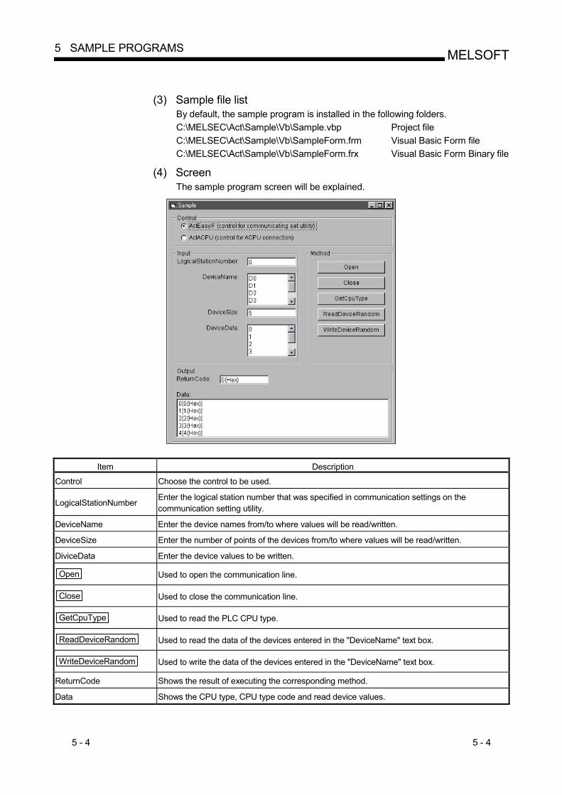
5 - 4 5 - 4
MELSOFT5 SAMPLE PROGRAMS
(3) Sample file list
By default, the sample program is installed in the following folders. C:\MELSEC\Act\Sample\Vb\Sample.vbp Project file C:\MELSEC\Act\Sample\Vb\SampleForm.frm Visual Basic Form file C:\MELSEC\Act\Sample\Vb\SampleForm.frx Visual Basic Form Binary file
(4) Screen
The sample program screen will be explained.
Item Description
Control Choose the control to be used.
LogicalStationNumber Enter the logical station number that was specified in communication settings on the communication setting utility.
DeviceName Enter the device names from/to where values will be read/written.
DeviceSize Enter the number of points of the devices from/to where values will be read/written.
DiviceData Enter the device values to be written.
Open Used to open the communication line.
Close Used to close the communication line.
GetCpuType Used to read the PLC CPU type.
ReadDeviceRandom Used to read the data of the devices entered in the "DeviceName" text box.
WriteDeviceRandom Used to write the data of the devices entered in the "DeviceName" text box.
ReturnCode Shows the result of executing the corresponding method.
Data Shows the CPU type, CPU type code and read device values.

5 - 5 5 - 5
MELSOFT5 SAMPLE PROGRAMS
5.1.2 Sample program for modem communication
This sample program monitors the devices of the PLC CPU corresponding to the specified logical station number using the ActEasyIF control. (1) Using method
Enter the value of the logical station number, to which modem communication settings have been made within the communication settings utility, into the "LogicalStationNumber" text box. If the password has been set to the module to be connected, enter the password into the "Password" text box. Enter the monitoring interval into the "MonitorInterval" text box. Enter the device name to be monitored into the "DeviceName" text box, and the number of device points into the "Size" text box. Clicking the MonitorStart button opens the communication line after connection
of the telephone line and reads the device values at the intervals specified with the RedDeviceBlock function. (For the logical station number that does not need connection of the telephone line, only the communication line is opened and the telephone line is not connected.) Clicking the MonitorStop button disconnects the telephone line after closing of
the communication line. If an error occurs during execution of this sample program, an error code appears in the "ReturnValue" text box. If the error code is displayed in the "ReturnValue" text box, click the GetErrorMessage button to display the error definition and corrective action
corresponding to the displayed error code. If an error occurs, confirm the error definition and remove the error cause.
(2) Instructions for use of the sample program (a) To use the ActEasyIF control, set the logical station number within the
communication settings utility before execution of this sample program. (b) When changing the logical station number, monitoring interval, device name
and number of read points, click the MonitorStop button to close the
communication line once, and click the MonitorStart button to resume
communication.
(3) Sample file list The sample program is installed into the following folders at the default installation.
C:\MELSEC\Act\Sample\Vb\ModemSample\ModemSample.vbp project file C: \MELSEC\Act\Sample\Vb\ModemSample\ModemSample.frm Visual Basic Form file C: \MELSEC\Act\Sample\Vb\ModemSample\ModemSample.frx Visual Basic Form Binary file

5 - 6 5 - 6
MELSOFT5 SAMPLE PROGRAMS
(4) Screen
The sample program screen will be explained.
Item Description
LogicalStationNumber Enter the logical station number set in the communication settings utility.
Password Enter the password when it is required.
MonitorInterval Set the monitoring interval. (Unit: s)
DeviceName Enter the device name to be monitored.
Size Enter the number of read points.
ReturnValue Displays the returned value of the executed method.
MonitorStart Used to open the communication line and start monitoring after connection of the telephone line.
MonitorStop Used to disconnect the telephone line and stop monitoring after closing of the communication line.
GetErrorMessage Used to get and display the error definition and corrective action for the error code in
"ReturnValue".

5 - 7 5 - 7
MELSOFT5 SAMPLE PROGRAMS
5.1.3 Type conversion sample program
This sample program reads/writes ASCII character string, 32-bit integer or real number data from/to the PLC CPU devices in the corresponding data format using the ActEasyIF control, and if an error occurs during execution, displays the error message using the ActSupport control.
(1) Using method
Load the form, type the logical number, which was specified in communication settings on the communication setting utility, in the "LogicalStationNumber" text box, and then click the Open button to open the communication line.
To write ASCII characters to the PLC CPU, type ASCII character data in the upper text box inside the "ASCII character" frame, and then click the Write
button inside that frame. (Write is executed within the range D0 to D9, regardless of the number of typed characters. When the number of characters is insufficient, the blanks are filled with 0 (Hex).) To read the ASCII characters, click the Read button in the "ASCII character"
frame. Data from the PLC CPU is displayed in the lower text box inside that frame. (Read is executed within the range D0 to D9.) To write a 32-bit integer to the PLC CPU, type 32-bit integer data in the upper text box inside the "32bit integer" frame, and then click the Write button inside
that frame. (Write is executed within the range D10 to D11.) To read the 32-bit integer, click the Read button in the "32bit integer" frame.
Data from the PLC CPU is displayed in the lower text box inside that frame. (Read is executed within the range D10 to D11.) To write a real number to the PLC CPU, type real number data in the upper text box inside the "Real number" frame, and then click the Write button inside that
frame. (Write is executed within the range D12 to D13.) To read the real number, click the Read button in the "Real number" frame.
Data from the PLC CPU is displayed in the lower text box inside that frame. (Read is executed within the range D12 to D13.) If an error occurs during execution, the error message and error code appear in the message box. If an error has occurred, refer to "6 ERROR CODES" and remove the error cause. Click the Close button to close the communication line.
5 - 8 5 - 8
MELSOFT5 SAMPLE PROGRAMS
(2) Precautions for use of the sample program
(a) When using the ActEasyIF control, make communication settings on the communication setting utility before running this sample program.
(b) If an error occurs due to other than the ActEasyIF control (e.g. a character
string or out-of-range value is typed as a 32-bit integer or real number), the corresponding error is displayed in the message box and then the program terminates.
(3) Sample file list
When installed on the default path, the sample program is installed into the following folder.
C:\MELSEC\Act\Sample\Vb\Sample_TypeConv\Sample_TypeConv.vbp Project file C:\MELSEC\Act\Sample\Vb\Sample_TypeConv\frm_Sample_TypeConv.frm Visual Basic Form file C:\MELSEC\Act\Sample\Vb\Sample_TypeConv\frm_Sample_TypeConv.frx Visual Basic Form Binary file

5 - 9 5 - 9
MELSOFT5 SAMPLE PROGRAMS
(4) Screen
The screen for the sample program will be explained.
Item Description
LogicalStationNumber Type the logical station number that was specified in communication settings on the communication setting utility.
Open Opens the communication line.
Close Closes the communication line.
Write Writes the ASCII character data, which was typed in the upper text box inside the frame, to the PLC CPU. "ASII character"
frame Read Displays the ASCII character data, which was read from the PLC CPU, in the lower text box inside the frame.
Write Writes the 32-bit integer data, which was typed in the upper text box inside the frame, to the PLC CPU. "32bit integer"
frame Read Displays the 32-bit integer data, which was read from the PLC CPU, in the lower text box inside the frame.
Write Writes the real number data, which was typed in the upper text box inside the frame, to the PLC CPU. "Real number"
frame Read Displays the real number data, which was read from the PLC CPU, in the lower text box inside the frame.

5 - 10 5 - 10
MELSOFT5 SAMPLE PROGRAMS
5.2 Visual C++ R 6.0 Sample Programs
This section explains the sample programs for Visual C++ R 6.0 which were created using the dispatch interface and custom interface.
5.2.1 Dispatch interface
This sample program is designed to read the type of the connection destination CPU and read/write device values using the ActAJ71QE71UDP control or ActEasyIF control on the dispatch interface. (1) Using method
Load the form and choose the control to be used. Clicking the Open Communication button opens the communication line
through Ethernet communication. By clicking the GetCpuType button, the type code of the PLC CPU which is
currently connecting the line appears in the "Output Data" text box (top) and the CPU type in the "Output Data" text box (bottom). Entering the device from where you want to read a value into the "Device Name" text box and clicking the GetDevice button shows the device data in the
"Output Data" text box (top). To write a device value, enter the device where you want to write a value into the "Device Name" text box and the device value to be written into the "Device Value" text box and click the SetDevice button.
Clicking the Close Communication button closes the communication line.
If an error occurs at the execution of any function, an error code appears in the "Return Value" text box. If an error has occurred, refer to "CHAPTER 6 ERROR CODES" and eliminate the error cause.
(2) Precautions for use of the sample program (a) When using the ActEasyIF control, set the Ethernet communication
information to the logical station number "2" on the communication settings utility before starting the sample program running.
(b) When changing the control used, click the Close Communication button to
close the communication line once, then change the control, and open the line again.

5 - 11 5 - 11
MELSOFT5 SAMPLE PROGRAMS
(3) Sample file list
The sample files are installed into the following folders at default installation. C:\MELSEC\Act\Sample\Vc\SampleEng\sampleEng.rc Resource file C:\MELSEC\Act\Sample\Vc\SampleEng\sampleEng.dsw Project work space C:\MELSEC\Act\Sample\Vc\SampleEng\sampleEng.dsp Project file C:\MELSEC\Act\Sample\Vc\SampleEng\sampleEng.cpp Class define file C:\MELSEC\Act\Sample\Vc\SampleEng\sampleEngDlg.cpp Dialog Implementation source file C:\MELSEC\Act\Sample\Vc\SampleEng\actaj71qe71udp.cpp ActAJ71QE71UDP Control source file C:\MELSEC\Act\Sample\Vc\SampleEng\actaj71qe71udp.h ActAJ71QE71UDP Control header file C:\MELSEC\Act\Sample\Vc\SampleEng\acteasyif.cpp ActEasyIF Control source file C:\MELSEC\Act\Sample\Vc\SampleEng\acteasyif.h ActEasyIF Control header file
(4) Screen The sample program screen will be explained.
Item Description
Control Used to choose the control to be used.
Open Communication Used to open the communication line.
GetCpuType Used to read the PLC CPU type.
Device Name Enter the device from/to where a value will be read/written.
Device Value Enter the device value to be written.
Close Communication Used to close the communication line.
GetDevice Used to read the data of the device entered into the "Device Name" text box.
SetDevice Used to write the data of the device entered into the "Device Name" text box.
Return Shows the result of executing the function.
Top Shows the CPU type code and read device value. Output
Bottom Shows the CPU type.

5 - 12 5 - 12
MELSOFT5 SAMPLE PROGRAMS
5.2.2 Custom interface
This sample program is designed to read the type of the connection destination CPU and read/write device values using the ActAJ71QE71UDP control or ActEasyIF control on the custom interface. (1) Using method
The using method is the same as that of the sample program for dispatch interface. Refer to "Section 5.2.1 Dispatch interface, (1) Using method".
(2) Precautions for use of the sample program The precautions are the same as those of the sample program for dispatch interface. Refer to "Section 5.2.1 Dispatch interface, (2) Precautions for use of the sample program".
(3) Sample file list The sample files are installed into the following folders at default installation.
C:\MELSEC\Act\Sample\Vc\CustomSampleEng\CustomSampleEng.rc Resource file C:\MELSEC\Act\Sample\Vc\CustomSampleEng\CustomSampleEng.dsw Project work space C:\MELSEC\Act\Sample\Vc\CustomSampleEng\CustomSampleEng.dsp Project file C:\MELSEC\Act\Sample\Vc\CustomSampleEng\CustomSampleDlgEng.cpp Dialog implementation source file
(4) Screen
The screen is the same as that of the the sample program for dispatch interface. Refer to "Section 5.2.1 Dispatch interface, (4) Screen".

5 - 13 5 - 13
MELSOFT5 SAMPLE PROGRAMS
5.2.3 Troubleshooting function sample program
This sample program performs the troubleshooting function using the ActSupport control with the dispatch interface. (1) Using method
Load the form. In the "ErrorCode" text box, enter the error code of which error definition you want to know. Clicking the GetErrorMessage button displays the error definition and corrective
action in the error definition displaying text box. The displayed error definitions and corrective actions are as indicated in "6.1 Error Codes Returned by the ACT Controls". Click the Exit button to exit from the sample program.
(2) Instructions for use of the sample program
(a) Enter the error codes in the "ErrorCode" text box with any of the error codes given in "6.1 Error Codes Returned by the ACT Controls" (0x********) or decimal numbers.
(3) Sample file list
The sample files are installed into the following folders at the time of default installation.
C:\MELSEC\Act\Sample\Vc\Sample_SupportEng\actsupport3.cpp Source file of ActSupport control C:\MELSEC\Act\Sample\Vc\Sample_SupportEng\ actsupport3.h Header file of ActSupport control C:\MELSEC\Act\Sample\Vc\Sample_SupportEng\resource.h Resource file C:\MELSEC\Act\Sample\Vc\Sample_SupportEng\Sample_Support.cpp Source file for class definition C:\MELSEC\Act\Sample\Vc\Sample_SupporEng\Sample_Support.dsp Project file C:\MELSEC\Act\Sample\Vc\Sample_SupportEng\Sample_Support.dsw Project work space C:\MELSEC\Act\Sample\Vc\Sample_SupportEng\Sample_Support.h Header file for class definition C:\MELSEC\Act\Sample\Vc\Sample_SupportEng\Sample_Support.rc Resource file C:\MELSEC\Act\Sample\Vc\Sample_SupportEng\Sample_SupportDlg.cpp Source file for dialog implementation C:\MELSEC\Act\Sample\Vc\Sample_SupportEng\Sample_SupportDlg.h Header file for dialog implementation

5 - 14 5 - 14
MELSOFT5 SAMPLE PROGRAMS
(4) Screen
The sample program screen will be explained.
Item Description
ErrorCode Enter the error code.
GetErrorMessage Used to read the error definition and corrective action of the error code entered in the "ErrorCode" text box.
Exit Used to exit from the sample program.
(Error definition displaying text box)
Displays the error definition and corrective action of the error code entered in the "ErrorCode" text box.
5 - 15 5 - 15
MELSOFT5 SAMPLE PROGRAMS
5.3 VBA Sample Programs
This section explains the sample programs for Excel and Access.
5.3.1 Excel sample program
This sample program is designed to log and graph the device values of the PLC CPU using the ActEasyIF control. This sample program was created on Excel 2000. (1) Using method
Open the sample sheet. Type the logical station number, which was specified in communication settings on the communication setting utility, in the "LogicalStationNumber" input cell. Type the first device of the devices whose data you want to read in the "DeviceName" input cell. Type the logging interval in the "LoggingTiming" input cell. Clicking the LoggingStart button starts logging.
When logging starts, the past 10 device values and line graphs appear on the graph. Clicking the LoggingStop button stops logging.
Note that the logging data on the screen are not cleared. If an error occurs during execution, the error message appears in the "Message" output cell and the error code appears in the "Return Code" output cell. If an error has occurred, refer to "6 ERROR CODES" and remove the error cause.
(2) Precautions for use of the sample program (a) Before running this sample program, make communication settings on the
communication setting utility.
(b) When changing the input value, click the LoggingStop button to stop logging
once, then change the input value, and click the LoggingStart button to start
logging.
(c) In this sample program, the number of device points to be logged is preset to 10 and the number of logging times to 10.
(3) Sample file
By default, the sample program is installed into the following folder. C:\MELSEC\Act\Sample\ExcelVBA\Sample\Sample.xls Excel file
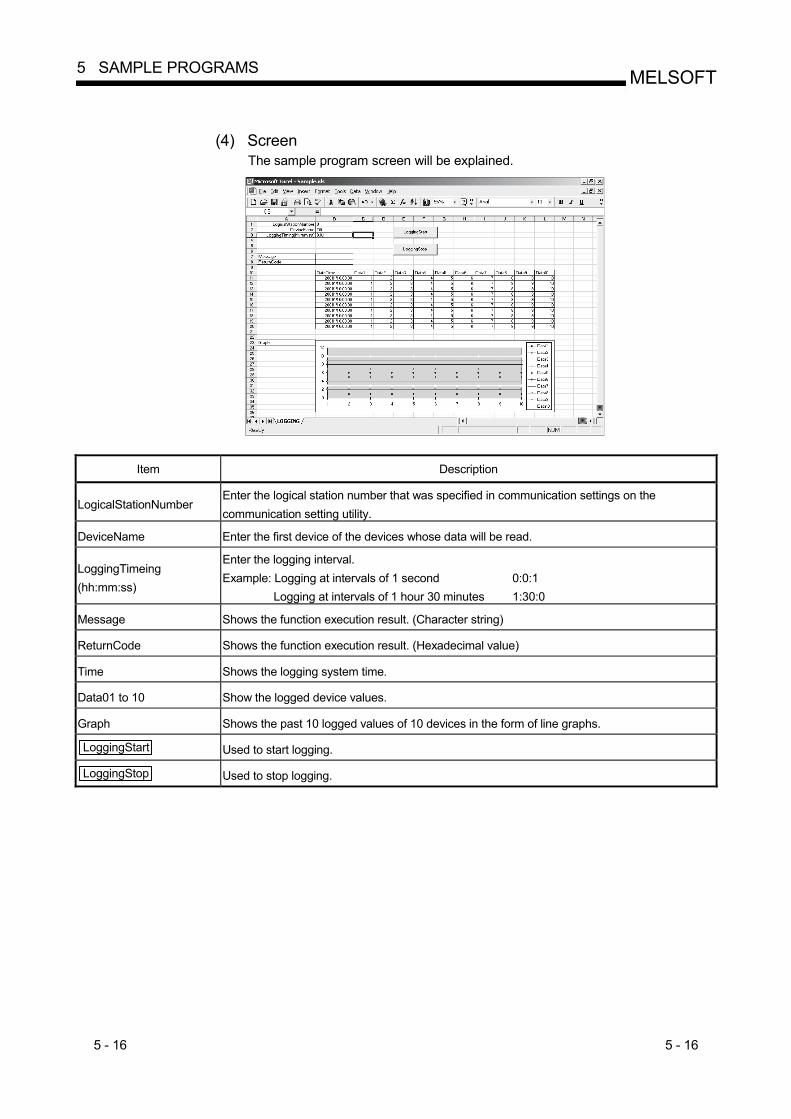
5 - 16 5 - 16
MELSOFT5 SAMPLE PROGRAMS
(4) Screen
The sample program screen will be explained.
Item Description
LogicalStationNumber Enter the logical station number that was specified in communication settings on the communication setting utility.
DeviceName Enter the first device of the devices whose data will be read.
LoggingTimeing (hh:mm:ss)
Enter the logging interval. Example: Logging at intervals of 1 second 0:0:1
Logging at intervals of 1 hour 30 minutes 1:30:0
Message Shows the function execution result. (Character string)
ReturnCode Shows the function execution result. (Hexadecimal value)
Time Shows the logging system time.
Data01 to 10 Show the logged device values.
Graph Shows the past 10 logged values of 10 devices in the form of line graphs.
LoggingStart Used to start logging.
LoggingStop Used to stop logging.
5 - 17 5 - 17
MELSOFT5 SAMPLE PROGRAMS
5.3.2 Excel sample program (Device read/write)
This sample program performs read/write the PLC CPU devices (D0 to D9) using the ActEasyIF control. Also, this program displays the error code and error message in the dialog box by using ActSupport control at an error occurrence. This sample program was created using Excel 2000. (1) Using method
Open the sample sheet. Enter the logical station number, to which communication settings have been made in the communication settings utility, into the "LogicalStationNumber" input cell. Clicking the DeviceRead button reads the D0 to D9 device values of the PLC
CPU and displays them in the DeviceRead area. Entering values into D0 to D9 in the DeviceWrite area and clicking the DeviceWrite button writes the values to D0 - D9 of the PLC CPU.
If read/write of the D0 - D9 devices fails, the error message corresponding to the error code is displayed in the dialog box.
(2) Precautions for use of the sample program (a) Before executing this sample program, make communication settings within
the communication settings utility.
(3) Sample file The sample program is installed into the following folder at the default installation. C:\MELSEC\Act\Sample\ExcelVBA\Sample\Sample_DeviceRW.xls Excel file

5 - 18 5 - 18
MELSOFT5 SAMPLE PROGRAMS
(4) Screen
The sample program screen will be explained.
Item Description
LogicalStationNumber Enter the logical station number to which communication settings have been made in the communication settings utility.
(DeviceRead area) Displays the D0 to D9 device values of the PLC CPU.
(DeviceWrite area) Enter the values to be written to D0 - D9 of the PLC CPU.
DeviceRead Used to read the D0 to D9 device values of the PLC CPU and display them in the DeviceRead area.
DeviceWrite Used to write the device values entered into D0 - D9 of the DeviceWrite area to D0 - D9 of the PLC CPU.

5 - 19 5 - 19
MELSOFT5 SAMPLE PROGRAMS
5.3.3 Access sample program
This sample program is designed to log and monitor the device values of the PLC CPU using the ActEasyIF control. This sample program was created on Access 2000. (1) Using method
Open the database. Type the logical station number, which was specified in communication settings on the communication setting utility, in the "LogicalStationNumber" text box. Type the logging interval in the "LoggingTiming" text box. Clicking the LoggingStart button starts logging.
Clicking the LoggingStop button stops logging.
Note that the logging data on the screen are not cleared. If an error occurs during execution, the error message and error code appear in the message box. If an error has occurred, refer to "6 ERROR CODES" and remove the error cause.
(2) Precautions for use of the sample program (a) Before running this sample program, make communication settings on the
communication setting utility.
(b) When changing the input value, click the LoggingStop button to stop logging
once, then change the input value, and click the LoggingStart button to start
logging.
(c) In this sample program, devices "D0" to "D4" are preset as the devices to be monitored, and "D10" to "17" as the devices to be logged. Also, monitoring is designed to occur at 1-second intervals.
(d) This sample program logs device values up to 100 times.
If the number of logging times exceeds 100, the oldest logging data is deleted and the newest logging data is registered.
(3) Sample file
By default, the sample program is installed into the following folder. C:\MELSEC\Act\Sample\AccessVBA\Sample\Sample.mdb Access file

5 - 20 5 - 20
MELSOFT5 SAMPLE PROGRAMS
(4) Screen
The sample program screen will be explained.
Item Description
LogicalStationNumber Enter the logical station number that was specified in communication settings on the communication setting utility.
LoggingTimeing Enter the logging interval. (Unit: Seconds)
LoggingData Shows the logged data.
OnDeviceStatus Shows the devices whose conditions held among the devices being monitored.
LoggingStart Used to start logging.
LoggingStop Used to stop logging.

5 - 21 5 - 21
MELSOFT5 SAMPLE PROGRAMS
5.4 VBScript Sample Program
This section describes the VBScript sample program. This sample program is designed to define the device values of the PLC CPU as the capacity and status of a tank and monitor their values using the ActMLEasyIF control. This sample program was created on Microsoft R FrontPage R 2000. (1) Using method
Opening the sample file opens the communication line to the PLC CPU used. After that, the device values of the PLC CPU are acquired at intervals of 1 second and are used to display the capacity and status of the tank. If an error occurs during execution, the error message and error code appear in the message box. If an error has occurred, refer to "6 ERROR CODES" and remove the error cause.
(2) Precautions for use of the sample program (a) Before running this sample program, make communication settings on the
communication setting utility to set the logical station number to "0".
(b) In this sample program, device "D100" is used to denote the tank capacity, and device "D101" to denote the tank status.
(3) Sample file
By default, the sample program is installed into the following folders. C:\MELSEC\Act\Sample\VBScript\SampleHTML\Sample.html HTML file C:\MELSEC\Act\Sample\VBScript\SampleHTML\Pics\Fill.gif Image file C:\MELSEC\Act\Sample\VBScript\SampleHTML\Pics\Frame.gif Image file C:\MELSEC\Act\Sample\VBScript\SampleHTML\Pics\LampERR.gif Image file C:\MELSEC\Act\Sample\VBScript\SampleHTML\Pics\LampOFF.gif Image file C:\MELSEC\Act\Sample\VBScript\SampleHTML\Pics\Tank.gif Image file

5 - 22 5 - 22
MELSOFT5 SAMPLE PROGRAMS
(4) Screen
The sample program screens will be explained. (a) Tank capacity : Empty
Tank status : Normal (b) Tank capacity : Full
Tank status : Error
Item Description remark
Tank capacity Indicates the tank capacity. (Within the range 0 < device value < 200)
Linked with device "D100"
Tank status Indicates the tank status. Normal (device value = 0) : Blue lamp lit Error (device value <> 0) : Red lamp lit
Linked with device "D101"

5 - 23 5 - 23
MELSOFT5 SAMPLE PROGRAMS
5.5 ASP Sample Program
This sample program is designed to read PLC CPU data and read device values using the ActMLEasyIF control.
(1) File structure
(a) Sample.asp (data input screen) Initial display screen used to set data for monitoring.
(b) SampleControl.asp (data getting screen)
Used to get the input data of Sample.asp, store them into the global variables, and check them for errors.
(c) SampleMon.asp (data display screen)
Displays data in accordance with the input data of Sample.asp. Displays a message if an error occurs.
(2) Using method
Store Sample.asp, SampleControl.asp and SampleMon.asp in the same folder on the WWW server. Browse the URL of Sample.asp on the Microsoft R Internet Explorer and display the initial screen. Entering "MonitorTiming", "LogicalStationNumber", "DeviceName" and "DeviceSize" on the initial screen and pressing the MonitorStart button start
Open processing, ReadDeviceBlock processing, GetCpuType processing and Close processing. The input data appear in "MonitorTiming:", "LogicalStationNumber:", "DeviceName:" and "DeviceSize:" on the data display screen. "Message:" displays error occurrence processing when an error occurs in the corresponding processing. "Return Code:" shows the result of the corresponding processing. "CpuType:" shows the type of the PLC CPU connected. "ReadData(Hex)" displays the device data of the PLC CPU connected. If an error has occurred, refer to "6 ERROR CODES" and remove the error cause. The data display screen repeats updating at the intervals of "MonitorTiming:". Pressing the Back button returns to the initial screen.
(3) Precautions for use of the sample program
Before running this sample program, make communication settings on the communication setting utility.
(4) Sample file list
By default, the sample program is installed in the following folders. C:\MELSEC\Act\Sample\VBScript\SampleASP\Sample-E.asp ASP file C:\MELSEC\Act\Sample\VBScript\SampleASP\SampleControl-E.asp ASP file C:\MELSEC\Act\Sample\VBScript\SampleASP\SampleMon-E.asp ASP file

5 - 24 5 - 24
MELSOFT5 SAMPLE PROGRAMS
(5) Screen
The sample program screens will be explained.
(a) Data input screen (Sample-E.asp)
Item Description
MonitorTiming Enter the monitoring intervals.
LogicalStationNumber Enter the logical station number.
DeviceName Enter the device name from where data will be read.
DeviceSize Enter the number of points of the devices from where data will be read.
MonitorStart Used to start monitor processing.
(b) Data getting screen (SampleControl.asp)
The data getting screen is a page used to store the data entered on the data input screen into the global variables and check them for errors. This screen is not displayed on the Internet Explorer screen.

5 - 25 5 - 25
MELSOFT5 SAMPLE PROGRAMS
(c) Data display screen (SampleMon-E.asp)
Item Description
MonitorTiming : Shows the monitoring intervals.
LogicalStationNumber : Shows the logical station number.
DeviceName : Shows the device name from where data will be read.
DeviceSize : Shows the number of points of the devices from where data will be read.
Message : Shows a message at error occurrence.
Return Code : Shows the execution result of the corresponding processing.
CpuType Shows the CPU type.
ReadData(Hex) Shows the read device values.
Back Used to return to the initial screen.

5 - 26 5 - 26
MELSOFT5 SAMPLE PROGRAMS
5.6 Visual Basic R .NET(Visual Studio R .NET 2003)Sample Programs
This section explains the sample programs for Visual Basic R .NET (Visual Studio R .NET 2003) that were created using the Act controls.
5.6.1 Type conversion sample program
This sample program reads/writes ASCII character string, 32-bit integer or real number data from/to the PLC CPU devices in the corresponding data format using the ActEasyIF control, and if an error occurs during execution, displays the error message using the ActSupport control.
(1) Using method
The using method is the same as for Visual Basic. Refer to Section 5.1.3.
(2) Precautions for use of the sample program The precautions are the same as for Visual Basic. Refer to Section 5.1.3.
(3) Sample file list
When installed on the default path, the sample program is installed into the following folder.
C:\MELSEC\Act\Sample\Vb.NET\Sample_TypeConv\AssemblyInfo.vb Assembly information file C:\MELSEC\Act\Sample\Vb.NET\Sample_TypeConv\Sample_TypeConv.resx Resource file C:\MELSEC\Act\Sample\Vb.NET\Sample_TypeConv\Sample_TypeConv.sln Visual Studio Solution file C:\MELSEC\Act\Sample\Vb.NET\Sample_TypeConv\Sample_TypeConv.vb VB file C:\MELSEC\Act\Sample\Vb.NET\Sample_TypeConv\Sample_TypeConv.vbproj VB main project file

5 - 27 5 - 27
MELSOFT5 SAMPLE PROGRAMS
(4) Screen
The screen for the sample program will be explained.
Item Description
LogicalStationNumber Type the logical station number that was specified in communication settings on the communication setting utility.
Open Opens the communication line.
Close Closes the communication line.
Write Writes the ASCII character data, which was typed in the upper text box inside the frame, to the PLC CPU. "ASII character"
frame Read Displays the ASCII character data, which was read from the PLC CPU, in the lower text box inside the frame.
Write Writes the 32-bit integer data, which was typed in the upper text box inside the frame, to the PLC CPU. "32bit integer"
frame Read Displays the 32-bit integer data, which was read from the PLC CPU, in the lower text box inside the frame.
Write Writes the real number data, which was typed in the upper text box inside the frame, to the PLC CPU. "Real number"
frame Read Displays the real number data, which was read from the PLC CPU, in the lower text box inside the frame.

5 - 28 5 - 28
MELSOFT5 SAMPLE PROGRAMS
5.6.2 Read/Write sample program
This sample program reads/writes the device values of the PLC CPU and monitors the device status using the ActEasyIF control or ActQCPUQ control.
(1) Using method
Load the form and choose the control to be used. Click the Open button to open the communication line.
When using the ActEasy IF control, type the logical number, which was specified in communication settings on the communication setting utility, in the "LogicalStationNumber" text box before clicking the Open button.
To execute random read, type the source device name and number of points, in the "DeviceName" and "DeviceSize" text boxes inside the "Random Read/Write" frame, and click the ReadDeviceRandom2 button. This displays the device
data in the "Data" text box inside the "Output" frame. To execute random write, type the destination device name and number of points, in the "DeviceName" and "DeviceSize" text boxes inside the "Random Read/Write" frame, and also type the device value, which will be written, in the "DeviceData" text box inside that frame, and click the WriteDeviceRandom2
button. This writes the device value to the PLC CPU. To execute block read, type the source device name and number of points, in the "DeviceName" and "DeviceSize" text boxes inside the "Block Read/Write" frame, and click the ReadDeviceBlock2 button. This displays the device data in the
"Data" text box inside the "Output" frame. To execute block write, type the destination device name and number of points, in the "DeviceName" and "DeviceSize" text boxes inside the "Block Read/Write" frame, and also type the device value, which will be written, in the "DeviceData" text box inside that frame, and click the WriteDeviceBlock2 button. This writes
the device value to the PLC CPU. To register the device status monitor, type the device name, number of points, device value and status monitor cycle in the "DeviceName", "DeviceSize", "DeviceData" and "MonitorCycle" text boxes inside the "Status Entry/Free" frame as the event occurrence conditions, and click the EntryDeviceStatus button.
When the registered event occurrence conditions are satisfied, the event data are displayed in the "Data" text box inside the "Output" frame. To cancel the already registered device status monitor, click the FreeDeviceStatus button.
If an error occurs during execution, the error code appears in the "Return Code" box inside the "Output" frame. If an error has occurred, refer to "6 ERROR CODES" and remove the error cause. Click the Close button to close the communication line.

5 - 29 5 - 29
MELSOFT5 SAMPLE PROGRAMS
(2) Precautions for use of the sample program
(a) When using the ActEasyIF control, make communication settings on the communication setting utility before running this sample program.
(b) When the ActQCPUQ control is used, this sample program is designed to use
the PLC CPU as "Q02(H)", the COM port as "COM1", and the transmission speed as 19200bps fixed. The specification can be changed by changing values of the corresponding property.
(c) When changing the control to be used, click the Close button to close the
communication line once, then change the control, and click the Open
button to reopen the line.
(3) Sample file list When installed on the default path, the sample program is installed into the following folder.
C:\MELSEC\Act\Sample\Vb.NET\Sample\AssemblyInfo.vb Assembly information file C:\MELSEC\Act\Sample\Vb.NET\Sample\Sample.resx Resource file C:\MELSEC\Act\Sample\Vb.NET\Sample\Sample.sln Visual Studio Solution file C:\MELSEC\Act\Sample\Vb.NET\Sample\Sample.vb VB file C:\MELSEC\Act\Sample\Vb.NET\Sample\Sample.vbproj VB main project file
C:\MELSEC\Act\Sample\Vb.NET\Sample_References\AssemblyInfo.vb Assembly information file C:\MELSEC\Act\Sample\Vb.NET\Sample_References\Sample_References.resx Resource file C:\MELSEC\Act\Sample\Vb.NET\Sample_References\Sample_References.sln Visual Studio Solution file C:\MELSEC\Act\Sample\Vb.NET\Sample_References\Sample_References.vb VB file C:\MELSEC\Act\Sample\Vb.NET\Sample_References\Sample_References.vbproj VB main project file
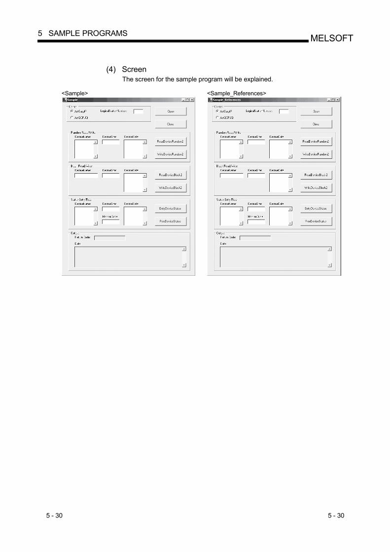
5 - 30 5 - 30
MELSOFT5 SAMPLE PROGRAMS
(4) Screen
The screen for the sample program will be explained.
<Sample> <Sample_References>

5 - 31 5 - 31
MELSOFT5 SAMPLE PROGRAMS
Item Description
ActEasyIF, ActQCPUQ
Choose the control to be used. "Control" frame
LogicalStationNumber Type the logical station number that was specified in communication settings on the communication setting utility.
Open Opens the communication line.
Close Closes the communication line.
DeviceName Type the device name for which random read/write will be executed.
DeviceSize Type the number of device points for which random read/write will be executed.
DeviceData Type the device value that will be written randomly.
ReadDeviceRandom2 Randomly reads device data from the PLC CPU to the data source typed in the "DeviceName" and "DeviceSize" text boxes inside the frame, and displays the data in the "Data" text box inside the "Output" frame.
"Random Read/Write" frame
WriteDeviceRandom2 Randomly writes device data to the PLC CPU from the data source typed in the "DeviceName", "DeviceSize" and "DeviceData" text boxes inside the frame.
DeviceName Type the device name for which block read/write will be executed.
DeviceSize Type the number of device points for which block read/write will be executed.
DeviceData Type the device values that will be block-written.
ReadDeviceBlock2 Block-reads device data from the PLC CPU to the data source typed in the "DeviceName" and "DeviceSize" text boxes inside the frame, and displays the data in the "Data" text box inside the "Output" frame.
"Block Read/Write" frame
WriteDeviceBlock2 Block-writes device data to the PLC CPU from the data source typed in the "DeviceName", "DeviceSize" and "DeviceData" text boxes inside the frame.
DeviceName Type the device name as an event occurrence condition.
DeviceSize Type the number of device points as an event occurrence condition.
MonitorCycle Type the event monitor cycle.
DeviceData Type the device value as an event occurrence condition.
EntryDeviceStatus
Registers the ON device status/event to the data source typed in the "DeviceName", "DeviceSize", "MonitorCycle" and "DeviceData" text boxes inside the frame. When the registered event occurrence conditions is satisfied, the event data is displayed in the "Data" text box of the "Output" frame.
"Status Entry/Free" frame
FreeDeviceStatus Deletes the ON device status/event already registered.
Return Code Displays the execution result of each method. "Output" frame
Data Displays the read device values.

5 - 32 5 - 32
MELSOFT5 SAMPLE PROGRAMS
5.7 Visual C++ R .NET(Visual Studio R .NET 2003) Sample Programs
This section explains the sample programs for Visual C++ R .NET (Visual Studio R .NET 2003) that were created using the Act controls.
5.7.1 Read/Write sample program
This sample program reads/writes the device values of the PLC CPU and monitors the device status using the ActEasyIF control or ActQCPUQ control.
(1) Using method
The using method is the same as for Visual Basic R .NET (Visual Studio R .NET 2003). Refer to Section 5.6.2.
(2) Precautions for use of the sample program
The precautions are the same as for Visual Basic R .NET (Visual Studio R .NET 2003). Refer to Section 5.6.2.
(3) Sample file list
When installed on the default path, the sample program is installed into the following folder.
C:\MELSEC\Act\Sample\Vc.NET\Sample\app.ico Icon file C:\MELSEC\Act\Sample\Vc.NET\Sample\app.rc Resource file C:\MELSEC\Act\Sample\Vc.NET\Sample\AssemblyInfo.cpp Assembly information file C:\MELSEC\Act\Sample\Vc.NET\Sample\Form1.cpp C++ source file C:\MELSEC\Act\Sample\Vc.NET\Sample\Form1.h C header file C:\MELSEC\Act\Sample\Vc.NET\Sample\Form1.resX Resource file C:\MELSEC\Act\Sample\Vc.NET\Sample\resource.h C header file C:\MELSEC\Act\Sample\Vc.NET\Sample\Sample.sln Visual Studio Solution file C:\MELSEC\Act\Sample\Vc.NET\Sample\Sample.vcproj VC++ main project file C:\MELSEC\Act\Sample\Vc.NET\Sample\stdafx.cpp C++ source file C:\MELSEC\Act\Sample\Vc.NET\Sample\stdafx.h C header file
C:\MELSEC\Act\Sample\Vc.NET\Sample_References\app.ico Icon file C:\MELSEC\Act\Sample\Vc.NET\Sample_References\app.rc Resource file C:\MELSEC\Act\Sample\Vc.NET\Sample_References\AssemblyInfo.cpp Assembly information file C:\MELSEC\Act\Sample\Vc.NET\Sample_References\Form1.cpp C++ source file C:\MELSEC\Act\Sample\Vc.NET\Sample_References\Form1.h C header file C:\MELSEC\Act\Sample\Vc.NET\Sample_References\Form1.resX Resource file C:\MELSEC\Act\Sample\Vc.NET\Sample_References\resource.h C header file C:\MELSEC\Act\Sample\Vc.NET\Sample_References\Sample_References.sln Visual Studio Solution file C:\MELSEC\Act\Sample\Vc.NET\Sample_References\Sample_References.vcproj VC++ main project file C:\MELSEC\Act\Sample\Vc.NET\Sample_References\stdafx.cpp C++ source file C:\MELSEC\Act\Sample\Vc.NET\Sample_References\stdafx.h C header file
(4) Screen
The screen is the same as for Visual Basic R .NET (Visual Studio R .NET 2003). Refer to Section 5.6.2.
5 - 33 5 - 33
MELSOFT5 SAMPLE PROGRAMS
5.8 Visual Basic R .NET (Visual Studio R 2005) Sample Program
In Visual Basic R .NET (Visual Studio R 2005), use converted sample program for Visual Basic R .NET (Visual Studio R .NET 2003). For a sample program for Visual Basic R .NET (Visual Studio R .NET 2003), refer to Section 5.6.
5.9 Visual C++ R .NET (Visual Studio R 2005) Sample Program
This section explains a sample program for Visual C++ R .NET (Visual Studio R 2005), created using Act control.
5.9.1 Read/Write sample program
This sample program reads/writes the device values of the PLC CPU and monitors the device status using the ActEasyIF control or ActQCPUQ control. (1) Using method
The using method is the same as for Visual Basic R .NET (Visual Studio R .NET 2003). Refer to Section 5.6.2.
(2) Precautions for use of the sample program The precautions are the same as for Visual Basic R .NET (Visual Studio R .NET 2003). Refer to Section 5.6.2.
(3) Sample file list When installed on the default path, the sample program is installed into the following folder.
C:\MELSEC\Act\Sample\Vc.NET\Sample2005\Sample2005.sln Visual Studio Solution file C:\MELSEC\Act\Sample\Vc.NET\Sample2005\Sample2005\app.ico Icon file C:\MELSEC\Act\Sample\Vc.NET\Sample2005\Sample2005\app.rc Resource file C:\MELSEC\Act\Sample\Vc.NET\Sample2005\Sample2005\AssemblyInfo.cpp Assembly information file C:\MELSEC\Act\Sample\Vc.NET\Sample2005\Sample2005\Form1.h C header file C:\MELSEC\Act\Sample\Vc.NET\Sample2005\Sample2005\Form1.resx Resource file C:\MELSEC\Act\Sample\Vc.NET\Sample2005\Sample2005\resource.h C header file C:\MELSEC\Act\Sample\Vc.NET\Sample2005\Sample2005\Sample2005.cpp C++ source file C:\MELSEC\Act\Sample\Vc.NET\Sample2005\Sample2005\Sample2005.vcproj VC++ main project file C:\MELSEC\Act\Sample\Vc.NET\Sample2005\Sample2005\stdafx.cpp C++ source file C:\MELSEC\Act\Sample\Vc.NET\Sample2005\Sample2005\stdafx.h C header file

5 - 34 5 - 34
MELSOFT5 SAMPLE PROGRAMS
C:\MELSEC\Act\Sample\Vc.NET\Sample_References2005\Sample_References2005.sln
Visual Studio Solution file C:\MELSEC\Act\Sample\Vc.NET\Sample_References2005\Sample_References2005\app.ico
Icon file C:\MELSEC\Act\Sample\Vc.NET\Sample_References2005\Sample_References2005\app.rc
Resource file C:\MELSEC\Act\Sample\Vc.NET\Sample_References2005\Sample_References2005\AssemblyInfo.cpp
Assembly information file C:\MELSEC\Act\Sample\Vc.NET\Sample_References2005\Sample_References2005\Form1.h
C header file C:\MELSEC\Act\Sample\Vc.NET\Sample_References2005\Sample_References2005\Form1.resx
Resource file C:\MELSEC\Act\Sample\Vc.NET\Sample_References2005\Sample_References2005\resource.h
C header file C:\MELSEC\Act\Sample\Vc.NET\Sample_References2005\Sample_References2005\Sample_References2005.cpp
C++ source file C:\MELSEC\Act\Sample\Vc.NET\Sample_References2005\Sample_References2005\Sample_References2005.vcproj
VC++ main project file C:\MELSEC\Act\Sample\Vc.NET\Sample_References2005\Sample_References2005\stdafx.cpp
C++ source file C:\MELSEC\Act\Sample\Vc.NET\Sample_References2005\Sample_References2005\stdafx.h
C header file (4) Screen
The screen is the same as for Visual Basic R .NET (Visual Studio R .NET 2003). Refer to Section 5.6.2.
6 - 1 6 - 1
MELSOFT6 ERROR CODES
6 ERROR CODES
This chapter describes the error codes returned by the ACT controls and the error codes returned by the CPUs, modules and network boards.
6.1 Error Codes Returned by the ACT Controls
The following table gives the error codes returned by the ACT controls.
Error Code Error Definition Corrective action 0x00000000 Normal end —————
0x01010002 Timeout error
Check the property timeout value. Check the settings in the communication settings utility. Check the PLC, Unit settings, state of the cable, etc. Close and Open again. Exit the program and restart the IBM-PC/AT compatible.
0x01010005 Message error.
Check the system noise. Check the property timeout value. Check the settings in the communication settings utility. Check the PLC, unit settings, status of the cable, etc. Close and Open again. Exit the program, restart the IBM-PC/AT compatible.
0x01010010 PLC No. error Communication could not be made with the specified station number.
Check the station number set on the communication setup utility. Check the station number set to ActStationNumber.
0x01010011 Mode Error Command not supported.
Check if the correct PLC type setting is done. Check the PLC, Unit settings, status of the cable, etc. Exit the program and restart the IBM-PC/AT compatible. Reinstall MX Component. Inform the telephone center of our company.
0x01010012 Special Unit Specification error. Check the specified address of the special unit.
0x01010013 Other data error Communication cannot be made for some cause.
Check that the system configuration is not an unsupported configuration. Check that the CPU type setting is correct. Exit the program and restart the IBM-PC/AT compatible. Contact our telephone center.
0x01010018 Remote request error Remote operation is being performed in the path different from the communicating path.
Cancel the remote operation being performed in the other path.
0x01010020 Link error Link communications could not be made.
Check that reset operation is not performed for the other end of communication, the control station (master station) or the station passed through by routing. Check that the network parameter setting is correct.
0x01010021 Special Unit Bus Error. There is no response from the special unit under consideration.
Repair or exchange the special unit under consideration. Exit the program and restart the IBM-PC/AT compatible. Reinstall MX Component. Inform the telephone center of our company.
0x01800001 No command error The method does not support. The corresponding method does not support.
0x01800002 Memory lock error Exit the program and restart the IBM-PC/AT compatible.
0x01800003 Memory securing error Exit the program and restart the IBM-PC/AT compatible. Exit other programs and secure free memory area.
0x01800004 DLL load error Exit the program and restart the IBM-PC/AT compatible. Exit other programs and secure free memory area. Reinstall MX Component.
6
6 - 2 6 - 2
MELSOFT6 ERROR CODES
Error Code Error Definition Corrective action
0x01800005 Resource securing error Exit the program and restart the IBM-PC/AT compatible. Exit other programs and secure free memory area.
0x01801001 Resource Timeout Error. The resource could not be retrieved within the specified time.
Execute again after the other object completes the communication. Execute again after increasing the timeout value. Exit the program and restart the IBM-PC/AT compatible. Reinstall MX Component.
0x01801002 Multi-line open error Exit the program and restart the IBM-PC/AT compatible. 0x01801003 Open not yet executed Exit the program and restart the IBM-PC/AT compatible.
0x01801004 Open Type error Exit the program and restart the IBM-PC/AT compatible. Reinstall MX Component. Inform the telephone center of our company.
0x01801005 Specified port error Exit the program and restart the IBM-PC/AT compatible. Reinstall MX Component.
0x01801006 Specified module error Exit the program and restart the IBM-PC/AT compatible. Reinstall MX Component.
0x01801007 Specified CPU error
Check the CPU type set to ActCpuType. Check that the system configuration is not an unsupported configuration. Exit the program and restart the IBM-PC/AT compatible. Reinstall MX Component. Check the packet type set to ActPacketType.
0x01801008 Target station access error Review the target station.
0x01801009 Registry open failure. Failed while opening data key of the registry.
Exit the program and restart the IBM-PC/AT compatible. Reinstall MX Component. Inform the telephone center of our company.
0x0180100A Packet Type Error. The packet type specified is incorrect.
Recheck the ActPacketType. Exit the program and restart the IBM-PC/AT compatible. Reinstall MX Component.
0x0180100B Protocol Type Error. The protocol specified is incorrect.
Exit the program and restart the IBM-PC/AT compatible. Reinstall MX Component. Inform the telephone center of our company.
0x0180100C Registry search failure Exit the program and restart the IBM-PC/AT compatible. Reinstall MX Component.
0x0180100D GetProcAddress failure Exit the program and restart the IBM-PC/AT compatible. Reinstall MX Component.
0x0180100E DLL non-load error Exit the program and restart the IBM-PC/AT compatible. Reinstall MX Component.
0x0180100F Another Object in execution Method cannot be executed because of exclusive control in progress
Execute again after some time.
0x01802001
Device error The device character string specified in the method is an unauthorised device character string.
Review the device name.
6

6 - 3 6 - 3
MELSOFT6 ERROR CODES
Error Code Error Definition Corrective action
0x01802002 Device number error The device character string number specified in the method is an unauthorised device number.
Review the device number.
0x01802003 Program Type Error Exit the program and restart the IBM-PC/AT compatible. Reinstall MX Component. Inform the telephone center of our company.
0x01802004 Sumcheck error The sumcheck value of the received data is abnormal.
Check the module side sumcheck setting. Check the sumcheck property of the control. Check the cable. Exit the program and restart the IBM-PC/AT compatible. Reinstall MX Component.
0x01802005 Size error The number of points specified in the method is unauthorised.
Check the number of points specified in the method. Review the system, e.g. PLC CPU, module setting and cable status. Exit the program and restart the IBM-PC/AT compatible. Reinstall MX Component.
0x01802006
Block number error The block specifying number in the device character string specified in the method is unauthorised.
Review the block specifying number in the device character string specified in the method.
0x01802007 Receive data error The data received is abnormal.
Review the system, e.g. PLC CPU, module setting and cable status. Check the cable. Exit the program and restart the IBM-PC/AT compatible.
0x01802008 Write Protect Error Exit the program and restart the IBM-PC/AT compatible. Reinstall MX Component. Inform the telephone center of our company.
0x01802009 Reading Parameters error Exit the program and restart the IBM-PC/AT compatible. Reinstall MX Component. Inform the telephone center of our company.
0x0180200A Writing Parameters error Exit the program and restart the IBM-PC/AT compatible. Reinstall MX Component. Inform the telephone center of our company.
0x0180200B
PLC type mismatch The CPU type set to the property and the CPU type set on the communication settings utility do not match the CPU type on the other end of communication.
Set the correct CPU type as the CPU type of the property.Set the correct CPU type on the communication settings utility. Review the system, e.g. PLC CPU, module setting and cable status.
0x0180200C Request Cancel Error The request was cancelled while being processed.
Exit the program and restart the IBM-PC/AT compatible. Reinstall MX Component. Inform the telephone center of our company.
0x0180200D Drive Name Error The specified drive name is incorrect.
Exit the program and restart the IBM-PC/AT compatible. Reinstall MX Component. Inform the telephone center of our company.
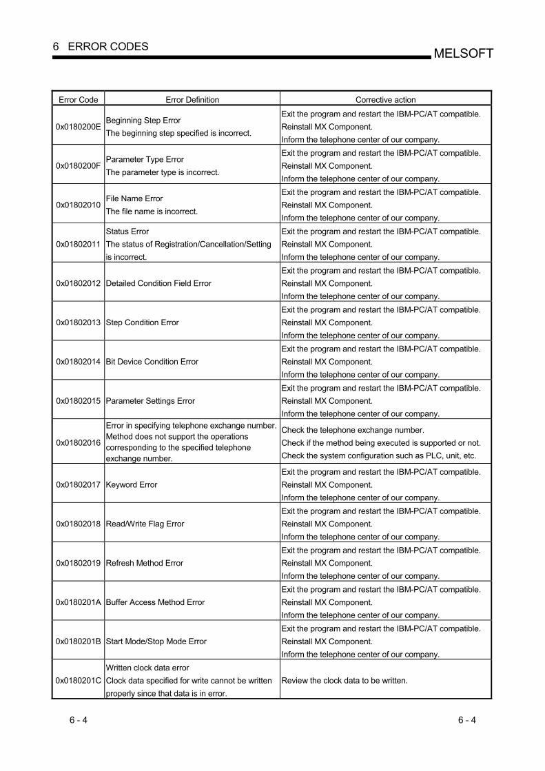
6 - 4 6 - 4
MELSOFT6 ERROR CODES
Error Code Error Definition Corrective action
0x0180200E Beginning Step Error The beginning step specified is incorrect.
Exit the program and restart the IBM-PC/AT compatible. Reinstall MX Component. Inform the telephone center of our company.
0x0180200F Parameter Type Error The parameter type is incorrect.
Exit the program and restart the IBM-PC/AT compatible. Reinstall MX Component. Inform the telephone center of our company.
0x01802010 File Name Error The file name is incorrect.
Exit the program and restart the IBM-PC/AT compatible. Reinstall MX Component. Inform the telephone center of our company.
0x01802011 Status Error The status of Registration/Cancellation/Setting is incorrect.
Exit the program and restart the IBM-PC/AT compatible. Reinstall MX Component. Inform the telephone center of our company.
0x01802012 Detailed Condition Field Error Exit the program and restart the IBM-PC/AT compatible. Reinstall MX Component. Inform the telephone center of our company.
0x01802013 Step Condition Error Exit the program and restart the IBM-PC/AT compatible. Reinstall MX Component. Inform the telephone center of our company.
0x01802014 Bit Device Condition Error Exit the program and restart the IBM-PC/AT compatible. Reinstall MX Component. Inform the telephone center of our company.
0x01802015 Parameter Settings Error Exit the program and restart the IBM-PC/AT compatible. Reinstall MX Component. Inform the telephone center of our company.
0x01802016
Error in specifying telephone exchange number.Method does not support the operations corresponding to the specified telephone exchange number.
Check the telephone exchange number. Check if the method being executed is supported or not. Check the system configuration such as PLC, unit, etc.
0x01802017 Keyword Error Exit the program and restart the IBM-PC/AT compatible. Reinstall MX Component. Inform the telephone center of our company.
0x01802018 Read/Write Flag Error Exit the program and restart the IBM-PC/AT compatible. Reinstall MX Component. Inform the telephone center of our company.
0x01802019 Refresh Method Error Exit the program and restart the IBM-PC/AT compatible. Reinstall MX Component. Inform the telephone center of our company.
0x0180201A Buffer Access Method Error Exit the program and restart the IBM-PC/AT compatible. Reinstall MX Component. Inform the telephone center of our company.
0x0180201B Start Mode/Stop Mode Error Exit the program and restart the IBM-PC/AT compatible. Reinstall MX Component. Inform the telephone center of our company.
0x0180201C Written clock data error Clock data specified for write cannot be written properly since that data is in error.
Review the clock data to be written.

6 - 5 6 - 5
MELSOFT6 ERROR CODES
Error Code Error Definition Corrective action
0x0180201D
Online clock data write error Write of clock data failed. Clock data cannot be written since the PLC CPU is during RUN.
Place the PLC CPU in the STOP status.
0x0180201E ROM drive Error Exit the program and restart the IBM-PC/AT compatible. Reinstall MX Component. Inform the telephone center of our company.
0x0180201F While Tracing error Invalid operation was carried out during trace.
Exit the program and restart the IBM-PC/AT compatible. Reinstall MX Component. Inform the telephone center of our company.
0x01802020 First I/O number error The first I/O number specified in the method is an unauthorised value.
Check the value of the first I/O number specified in the method. Using the GPP function, check the PLC CPU parameters (I/O assignment). Exit the program and restart the IBM-PC/AT compatible.
0x01802021 First address error The buffer address specified in the method is an unauthorised value.
Check the value of the buffer address specified in the method. Exit the program and restart the IBM-PC/AT compatible.
0x01802022 Pattern Error Exit the program and restart the IBM-PC/AT compatible. Reinstall MX Component. Inform the telephone center of our company.
0x01802023 SFC Block No. Error Exit the program and restart the IBM-PC/AT compatible. Reinstall MX Component. Inform the telephone center of our company.
0x01802024 SFC Step No. Error Exit the program and restart the IBM-PC/AT compatible. Reinstall MX Component. Inform the telephone center of our company.
0x01802025 Step No. Error Exit the program and restart the IBM-PC/AT compatible. Reinstall MX Component. Inform the telephone center of our company.
0x01802026 Data Error Exit the program and restart the IBM-PC/AT compatible. Reinstall MX Component. Inform the telephone center of our company.
0x01802027 System Data Error Exit the program and restart the IBM-PC/AT compatible. Reinstall MX Component. Inform the telephone center of our company.
0x01802028 Error in number of TC settings Value Exit the program and restart the IBM-PC/AT compatible. Reinstall MX Component. Inform the telephone center of our company.
0x01802029 Clear Mode Error Exit the program and restart the IBM-PC/AT compatible. Reinstall MX Component. Inform the telephone center of our company.
0x0180202A Signal Flow Error Exit the program and restart the IBM-PC/AT compatible. Reinstall MX Component. Inform the telephone center of our company.

6 - 6 6 - 6
MELSOFT6 ERROR CODES
Error Code Error Definition Corrective action
0x0180202B Version Control Error Exit the program and restart the IBM-PC/AT compatible. Reinstall MX Component. Inform the telephone center of our company.
0x0180202C Monitor Not Registered error Exit the program and restart the IBM-PC/AT compatible. Reinstall MX Component. Inform the telephone center of our company.
0x0180202D PI Type Error Exit the program and restart the IBM-PC/AT compatible. Reinstall MX Component. Inform the telephone center of our company.
0x0180202E PI No Error Exit the program and restart the IBM-PC/AT compatible. Reinstall MX Component. Inform the telephone center of our company.
0x0180202F Error in Number of PIs Exit the program and restart the IBM-PC/AT compatible. Reinstall MX Component. Inform the telephone center of our company.
0x01802030 Shift Error Exit the program and restart the IBM-PC/AT compatible. Reinstall MX Component. Inform the telephone center of our company.
0x01802031 File Type Error Exit the program and restart the IBM-PC/AT compatible. Reinstall MX Component. Inform the telephone center of our company.
0x01802032 Specified Unit error Exit the program and restart the IBM-PC/AT compatible. Reinstall MX Component. Inform the telephone center of our company.
0x01802033 Error check flag Error Exit the program and restart the IBM-PC/AT compatible. Reinstall MX Component. Inform the telephone center of our company.
0x01802034 Step RUN operation error Exit the program and restart the IBM-PC/AT compatible. Reinstall MX Component. Inform the telephone center of our company.
0x01802035 Step RUN data error Exit the program and restart the IBM-PC/AT compatible. Reinstall MX Component. Inform the telephone center of our company.
0x01802036 During Step RUN error Exit the program and restart the IBM-PC/AT compatible. Reinstall MX Component. Inform the telephone center of our company.
0x01802037 Write error while running program corresponding to E2PROM
Exit the program and restart the IBM-PC/AT compatible. Reinstall MX Component. Inform the telephone center of our company.
0x01802038
Clock data read/write error The clock data read/write method was executed for the PLC CPU which does not have the clock devices.
Do not execute clock data read/write.
0x01802039 Trace not completed error Exit the program and restart the IBM-PC/AT compatible. Reinstall MX Component. Inform the telephone center of our company.

6 - 7 6 - 7
MELSOFT6 ERROR CODES
Error Code Error Definition Corrective action
0x0180203A Registration Clear Flag Error Exit the program and restart the IBM-PC/AT compatible. Reinstall MX Component. Inform the telephone center of our company.
0x0180203B Operation error Exit the program and restart the IBM-PC/AT compatible. Reinstall MX Component. Inform the telephone center of our company.
0x0180203C Error in the number of exchanges Exit the program and restart the IBM-PC/AT compatible. Reinstall MX Component. Inform the telephone center of our company.
0x0180203D Error in number of loops specified Exit the program and restart the IBM-PC/AT compatible. Reinstall MX Component. Inform the telephone center of our company.
0x0180203E Retrieve data selection Exit the program and restart the IBM-PC/AT compatible. Reinstall MX Component. Inform the telephone center of our company.
0x0180203F Error in number of SFC cycles Exit the program and restart the IBM-PC/AT compatible. Reinstall MX Component. Inform the telephone center of our company.
0x01802040 Motion PLC Error Exit the program and restart the IBM-PC/AT compatible. Reinstall MX Component. Inform the telephone center of our company.
0x01802041 Motion PLC Communication error Exit the program and restart the IBM-PC/AT compatible. Reinstall MX Component. Inform the telephone center of our company.
0x01802042 Fixed execution time setting error Exit the program and restart the IBM-PC/AT compatible. Reinstall MX Component. Inform the telephone center of our company.
0x01802043 Error in number of functions Exit the program and restart the IBM-PC/AT compatible. Reinstall MX Component. Inform the telephone center of our company.
0x01802044 System information specification error Exit the program and restart the IBM-PC/AT compatible. Reinstall MX Component. Inform the telephone center of our company.
0x01802045 Registration Condition Not Formed error Exit the program and restart the IBM-PC/AT compatible. Reinstall MX Component. Inform the telephone center of our company.
0x01802046 Function No. Error Exit the program and restart the IBM-PC/AT compatible. Reinstall MX Component. Inform the telephone center of our company.
0x01802047 RAM drive error Exit the program and restart the IBM-PC/AT compatible. Reinstall MX Component. Inform the telephone center of our company.
0x01802048 ROM drive error at the booting side Exit the program and restart the IBM-PC/AT compatible. Reinstall MX Component. Inform the telephone center of our company.

6 - 8 6 - 8
MELSOFT6 ERROR CODES
Error Code Error Definition Corrective action
0x01802049 Transfer mode specification error at the booting side
Exit the program and restart the IBM-PC/AT compatible. Reinstall MX Component. Inform the telephone center of our company.
0x0180204A Insufficient memory error Exit the program and restart the IBM-PC/AT compatible. Reinstall MX Component. Inform the telephone center of our company.
0x0180204B Back up drive ROM error Exit the program and restart the IBM-PC/AT compatible. Reinstall MX Component. Inform the telephone center of our company.
0x0180204C Block size error Exit the program and restart the IBM-PC/AT compatible. Reinstall MX Component. Inform the telephone center of our company.
0x0180204D Detached during RUN state error Exit the program and restart the IBM-PC/AT compatible. Reinstall MX Component. Inform the telephone center of our company.
0x0180204E Unit Already Registered error Exit the program and restart the IBM-PC/AT compatible. Reinstall MX Component. Inform the telephone center of our company.
0x0180204F Password Registration Data Full error Exit the program and restart the IBM-PC/AT compatible. Reinstall MX Component. Inform the telephone center of our company.
0x01802050 Password Not Registered error Exit the program and restart the IBM-PC/AT compatible. Reinstall MX Component. Inform the telephone center of our company.
0x01802051 Remote Password Error Exit the program and restart the IBM-PC/AT compatible. Reinstall MX Component. Inform the telephone center of our company.
0x01802052 IP Address Error Exit the program and restart the IBM-PC/AT compatible. Reinstall MX Component. Inform the telephone center of our company.
0x01802053 Timeout value out of range error Exit the program and restart the IBM-PC/AT compatible. Reinstall MX Component. Inform the telephone center of our company.
0x01802054 Command not detected error Exit the program and restart the IBM-PC/AT compatible. Reinstall MX Component. Inform the telephone center of our company.
0x01802055 Trace execution type error Exit the program and restart the IBM-PC/AT compatible. Reinstall MX Component. Inform the telephone center of our company.
0x01802056 Version error Exit the program and restart the IBM-PC/AT compatible. Reinstall MX Component. Inform the telephone center of our company.
0x01802057 Tracking cable error The tracking cable is faulty. The PLC CPU status is error.
Reexamine the system such as the PLC CPU, module setting and cable status.
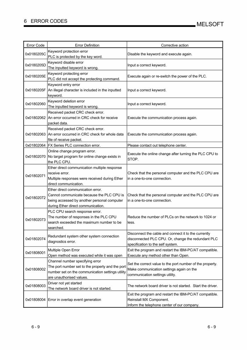
6 - 9 6 - 9
MELSOFT6 ERROR CODES
Error Code Error Definition Corrective action
0x0180205C Keyword protection error PLC is protected by the key word.
Disable the keyword and execute again.
0x0180205D Keyword disable error The inputted keyword is wrong.
Input a correct keyword.
0x0180205E Keyword protecting error PLC did not accept the protecting command.
Execute again or re-switch the power of the PLC.
0x0180205F Keyword entry error An illegal character is included in the inputted keyword.
Input a correct keyword.
0x01802060 Keyword deletion error The inputted keyword is wrong.
Input a correct keyword.
0x01802062 Received packet CRC check error. An error occurred in CRC check for receive packet data.
Execute the communication process again.
0x01802063 Received packet CRC check error. An error occurred in CRC check for whole data file of receive packet.
Execute the communication process again.
0x01802064 FX Series PLC connection error. Please contact out telephone center.
0x01802070 Online change program error. No target program for online change exists in the PLC CPU.
Execute the online change after turning the PLC CPU to STOP.
0x01802071
Ether direct communication multiple response receive error. Multiple responses were received during Ether direct communication.
Check that the personal computer and the PLC CPU are in a one-to-one connection.
0x01802072
Ether direct communication error. Cannot communicate because the PLC CPU is being accessed by another personal computer during Ether direct communication.
Check that the personal computer and the PLC CPU are in a one-to-one connection.
0x01802073
PLC CPU search response error. The number of responses in the PLC CPU search exceeded the maximum number to be searched.
Reduce the number of PLCs on the network to 1024 or less.
0x01802074 Redundant system other system connection diagnostics error.
Disconnect the cable and connect it to the currently disconnected PLC CPU. Or, change the redundant PLC specification to the self system.
0x01808001 Multiple Open Error Open method was executed while it was open
Exit the program and restart the IBM-PC/AT compatible. Execute any method other than Open.
0x01808002
Channel number specifying error The port number set to the property and the port number set on the communication settings utility are unauthorised values.
Set the correct value to the port number of the property. Make communication settings again on the communication settings utility.
0x01808003 Driver not yet started The network board driver is not started.
The network board driver is not started. Start the driver.
0x01808004 Error in overlap event generation Exit the program and restart the IBM-PC/AT compatible. Reinstall MX Component. Inform the telephone center of our company.

6 - 10 6 - 10
MELSOFT6 ERROR CODES
Error Code Error Definition Corrective action
0x01808005 MUTEX generation error Creation of MUTEX to exercise exclusive control failed.
Exit the program and restart the IBM-PC/AT compatible. Reinstall MX Component.
0x01808006 Error in socket object generation Socket object could not be created
Exit the program and restart the IBM-PC/AT compatible. Reinstall MX Component. Inform the telephone center of our company.
0x01808007 Socket object generation error Creation of the Socket object failed.
Check for a running application which uses the same port number. Retry after changing the port number value of the property. Retry after changing the port number value on the communication settings utility. Make Ethernet board and protocol settings on the control panel of the OS. Exit the program and restart the IBM-PC/AT compatible.
0x01808008 Port connection error Establishment of connection failed. The other end does not respond.
Review the IP address and port number values of the properties. Review the port number value on the communication settings utility. Review the system, e.g. PLC CPU, module setting and cable status. Exit the program and restart the IBM-PC/AT compatible.
0x01808009
COM port handle error The handle of the COM port cannot be acquired.The COM port objet cannot be copied. The SOCKET object cannot be copied.
Check for an application which uses the COM port. Exit the program and restart the IBM-PC/AT compatible.
0x0180800A Buffer size setting error Setting of the COM port buffer size failed.
Check for an application which uses the COM port. Make COM port setting on the control panel of the OS. Exit the program and restart the IBM-PC/AT compatible.
0x0180800B DCB value acquisition error Acquisition of the COM port DCB value failed.
Check for an application which uses the COM port. Make COM port setting on the control panel of the OS. Exit the program and restart the IBM-PC/AT compatible.
0x0180800C DCB setting error Setting of the COM port DCB value failed.
Check for an application which uses the COM port. Make COM port setting on the control panel of the OS. Exit the program and restart the IBM-PC/AT compatible.
0x0180800D Time-out value setting error Setting of the COM port time-out value failed.
Review the time-out value of the property. Review the time-out value on the communication settings utility. Check for an application which uses the COM port. Make COM port setting on the control panel of the OS. Exit the program and restart the IBM-PC/AT compatible.
0x0180800E Shared memory open error Open processing of shared memory failed.
Check whether the GX Simulator has started. Exit the program and restart the IBM-PC/AT compatible.
0x01808101 Duplex close error Exit the program and restart the IBM-PC/AT compatible.
0x01808102 Handle close error Closing of the COM port handle failed.
Exit the program and restart the IBM-PC/AT compatible.
0x01808103 Driver close error Closing of the driver handle failed.
Exit the program and restart the IBM-PC/AT compatible.
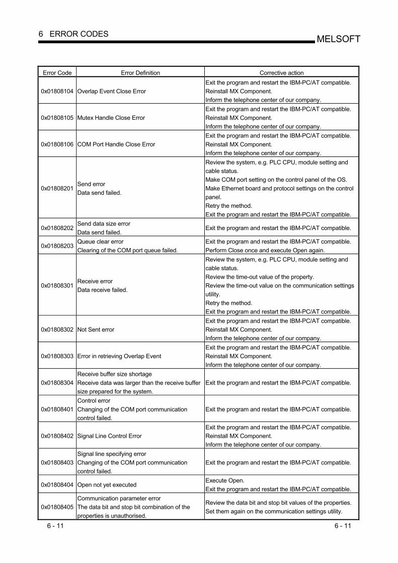
6 - 11 6 - 11
MELSOFT6 ERROR CODES
Error Code Error Definition Corrective action
0x01808104 Overlap Event Close Error Exit the program and restart the IBM-PC/AT compatible. Reinstall MX Component. Inform the telephone center of our company.
0x01808105 Mutex Handle Close Error Exit the program and restart the IBM-PC/AT compatible. Reinstall MX Component. Inform the telephone center of our company.
0x01808106 COM Port Handle Close Error Exit the program and restart the IBM-PC/AT compatible. Reinstall MX Component. Inform the telephone center of our company.
0x01808201 Send error Data send failed.
Review the system, e.g. PLC CPU, module setting and cable status. Make COM port setting on the control panel of the OS. Make Ethernet board and protocol settings on the control panel. Retry the method. Exit the program and restart the IBM-PC/AT compatible.
0x01808202 Send data size error Data send failed.
Exit the program and restart the IBM-PC/AT compatible.
0x01808203 Queue clear error Clearing of the COM port queue failed.
Exit the program and restart the IBM-PC/AT compatible. Perform Close once and execute Open again.
0x01808301 Receive error Data receive failed.
Review the system, e.g. PLC CPU, module setting and cable status. Review the time-out value of the property. Review the time-out value on the communication settings utility. Retry the method. Exit the program and restart the IBM-PC/AT compatible.
0x01808302 Not Sent error Exit the program and restart the IBM-PC/AT compatible. Reinstall MX Component. Inform the telephone center of our company.
0x01808303 Error in retrieving Overlap Event Exit the program and restart the IBM-PC/AT compatible. Reinstall MX Component. Inform the telephone center of our company.
0x01808304 Receive buffer size shortage Receive data was larger than the receive buffer size prepared for the system.
Exit the program and restart the IBM-PC/AT compatible.
0x01808401 Control error Changing of the COM port communication control failed.
Exit the program and restart the IBM-PC/AT compatible.
0x01808402 Signal Line Control Error Exit the program and restart the IBM-PC/AT compatible. Reinstall MX Component. Inform the telephone center of our company.
0x01808403 Signal line specifying error Changing of the COM port communication control failed.
Exit the program and restart the IBM-PC/AT compatible.
0x01808404 Open not yet executed Execute Open. Exit the program and restart the IBM-PC/AT compatible.
0x01808405 Communication parameter error The data bit and stop bit combination of the properties is unauthorised.
Review the data bit and stop bit values of the properties. Set them again on the communication settings utility.

6 - 12 6 - 12
MELSOFT6 ERROR CODES
Error Code Error Definition Corrective action
0x01808406 Transmission speed value specifying error The transmission speed of the property is unauthorised.
Review the transmission speed value of the property. Set it again on the communication settings utility.
0x01808407 Data length error The data bit value of the property is unauthorised.
Review the data bit value of the property. Set it again on the communication settings utility.
0x01808408 Parity specifying error The parity value of the property is unauthorised.
Review the parity value of the property. Set it again on the communication settings utility.
0x01808409 Stop bit specifying error The stop bit value of the property is unauthorised.
Review the stop bit value of the property. Set it again on the communication settings utility.
0x0180840A Communication control setting error The control value of the property is unauthorised.
Review the control value of the property. Set it again on the communication settings utility.
0x0180840B Time-out error Though the time-out period had elapsed, data could not be received.
Review the time-out value of the property. Set it again on the communication settings utility. Review the system, e.g. PLC CPU, module setting and cable status. Retry the method. Perform Close once and execute Open again. Exit the program and restart the IBM-PC/AT compatible.
0x0180840C Connect error Exit the program and restart the IBM-PC/AT compatible. 0x0180840D Duplex connect error Exit the program and restart the IBM-PC/AT compatible.
0x0180840E Attach failure Attaching of the socket object failed.
Exit the program and restart the IBM-PC/AT compatible.
0x0180840F Signal line status acquisition failure Acquisition of the COM port signal line status failed.
Exit the program and restart the IBM-PC/AT compatible.
0x01808410 CD signal line OFF The CD signal on the other end of communication is in the OFF status.
Review the system, e.g. PLC CPU, module setting and cable status. Exit the program and restart the IBM-PC/AT compatible.
0x01808411 Password mismatch error Check the remote password of the property.
0x01808412 TEL Communication Error Exit the program and restart the IBM-PC/AT compatible. Reinstall MX Component. Inform the telephone center of our company.
0x01808501 USB driver load error Loading of the USB driver failed.
Exit the program and restart the IBM-PC/AT compatible. Reinstall MX Component.
0x01808502 USB driver connect error Connection of the USB driver failed.
Exit the program and restart the IBM-PC/AT compatible. Reinstall MX Component.
0x01808503 USB driver send error Data send failed.
Review the system, e.g. PLC CPU, module setting and cable status. Make USB setting on the control panel (device manger) of the OS. Retry the method. Exit the program and restart the IBM-PC/AT compatible.

6 - 13 6 - 13
MELSOFT6 ERROR CODES
Error Code Error Definition Corrective action
0x01808504 USB driver receive error Data receive failed.
Review the system, e.g. PLC CPU, module setting and cable status. Make USB setting on the control panel (device manger) of the OS. Retry the method. Exit the program and restart the IBM-PC/AT compatible.
0x01808505 USB Driver Timeout Error
Recheck the timeout value. Exit the program and restart the IBM-PC/AT compatible. Reinstall MX Component. Inform the telephone center of our company.
0x01808506 USB driver initialisation error Initialisation of the USB driver failed.
Make USB setting on the control panel (device manger) of the OS. Exit the program and restart the IBM-PC/AT compatible.
0x01808507 Other USB error Error related to data send/receive occurred.
Disconnect the cable once, then reconnect. Exit the program and restart the IBM-PC/AT compatible. Reinstall MX Component.
0x02000001 Points Exceeded error The number of points registered in the monitoring server is very high.
Reduce the no. of points registered by the monitor. Exit the program and restart the IBM-PC/AT compatible. Reinstall MX Component. Inform the telephone center of our company.
0x02000002 Shared memory creation error Failed in creating shared memory.
Exit the program and restart the IBM-PC/AT compatible. Reinstall MX Component. Inform the telephone center of our company.
0x02000003 Shared memory access error Exit the program and restart the IBM-PC/AT compatible. Reinstall MX Component. Inform the telephone center of our company.
0x02000004 Memory Secure error Failed in securing memory for the monitoring server.
Close the other applications. Increase the system memory. Exit the program and restart the IBM-PC/AT compatible. Reinstall MX Component. Inform the telephone center of our company.
0x02000005 Device Not Registered error Monitor has not been registered
Register the monitor in the monitoring server. Exit the program and restart the IBM-PC/AT compatible. Reinstall MX Component. Inform the telephone center of our company.
0x02000006 Monitoring Server Startup Error Monitoring Server is not started.
Start the Monitoring Server. Exit the program and restart the IBM-PC/AT compatible. Reinstall MX Component. Inform the telephone center of our company.
0x02000010 Yet to retrieve Device Value error Monitoring is not yet completed
Try to retrieve the value again after waiting for a fixed amount of time. Exit the program and restart the IBM-PC/AT compatible. Reinstall MX Component. Inform the telephone center of our company.
0x03000001 Command not Supported. Command is not supported.
Exit the program and restart the IBM-PC/AT compatible. Reinstall MX Component. Inform the telephone center of our company.
0x03000002 Memory Lock Error Failed while locking memory.
Exit the program and restart the IBM-PC/AT compatible. Reinstall MX Component. Inform the telephone center of our company.

6 - 14 6 - 14
MELSOFT6 ERROR CODES
Error Code Error Definition Corrective action
0x03000003 Error Securing Memory Failed in securing the memory.
Exit the program and restart the IBM-PC/AT compatible. Reinstall MX Component. Inform the telephone center of our company.
0x03000004 DLL read error Failed in reading DLL.
Exit the program and restart the IBM-PC/AT compatible. Reinstall MX Component. Inform the telephone center of our company.
0x03000005 Error in securing Resources. Failed in securing the resources.
Exit the program and restart the IBM-PC/AT compatible. Reinstall MX Component. Inform the telephone center of our company.
0x03010001 File Creation Error Failed in creating the file.
Check if there is enough space on the hard disk. Exit the program and restart the IBM-PC/AT compatible. Reinstall MX Component. Inform the telephone center of our company.
0x03010002 File Open Error Failed to open the file.
Exit the program and restart the IBM-PC/AT compatible. Reinstall MX Component. Inform the telephone center of our company.
0x03010003 Buffer Size Error The buffer size specified is either incorrect or not enough.
Exit the program and restart the IBM-PC/AT compatible. Reinstall MX Component. Inform the telephone center of our company.
0x03010004 SIL Sentence formation error SIL sentence formation is incorrect.
Exit the program and restart the IBM-PC/AT compatible. Reinstall MX Component. Inform the telephone center of our company.
0x03010005 Filename Error The specified filename is too long.
Specify a shorter filename. Exit the program and restart the IBM-PC/AT compatible. Reinstall MX Component. Inform the telephone center of our company.
0x03010006 File does not exist error. The specified file does not exist.
Check the filename. Check if the file exists or not. Exit the program and restart the IBM-PC/AT compatible. Reinstall MX Component. Inform the telephone center of our company.
0x03010007 File Structure Error The data structure in the specified file is incorrect.
Exit the program and restart the IBM-PC/AT compatible. Reinstall MX Component. Inform the telephone center of our company.
0x03010008 File already exists error The specified file already exists.
Check the filename. Exit the program and restart the IBM-PC/AT compatible. Reinstall MX Component. Inform the telephone center of our company.
0x03010009 File does not exist error The specified file does not exist.
Check the filename. Exit the program and restart the IBM-PC/AT compatible. Reinstall MX Component. Inform the telephone center of our company.
0x0301000A File Deletion Error The specified file could not be deleted.
Exit the program and restart the IBM-PC/AT compatible. Reinstall MX Component. Inform the telephone center of our company.
0x0301000B Multiple Open Error The specified project has been opened twice.
Exit the program and restart the IBM-PC/AT compatible. Reinstall MX Component. Inform the telephone center of our company.
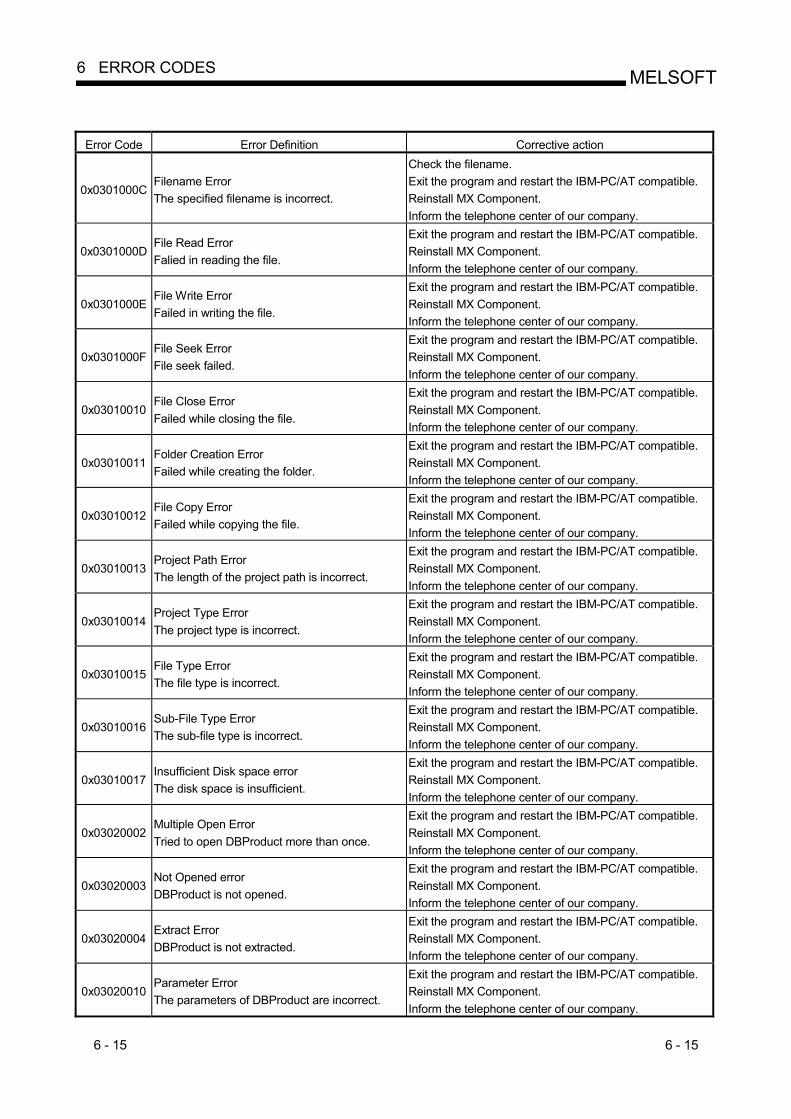
6 - 15 6 - 15
MELSOFT6 ERROR CODES
Error Code Error Definition Corrective action
0x0301000C Filename Error The specified filename is incorrect.
Check the filename. Exit the program and restart the IBM-PC/AT compatible. Reinstall MX Component. Inform the telephone center of our company.
0x0301000D File Read Error Falied in reading the file.
Exit the program and restart the IBM-PC/AT compatible. Reinstall MX Component. Inform the telephone center of our company.
0x0301000E File Write Error Failed in writing the file.
Exit the program and restart the IBM-PC/AT compatible. Reinstall MX Component. Inform the telephone center of our company.
0x0301000F File Seek Error File seek failed.
Exit the program and restart the IBM-PC/AT compatible. Reinstall MX Component. Inform the telephone center of our company.
0x03010010 File Close Error Failed while closing the file.
Exit the program and restart the IBM-PC/AT compatible. Reinstall MX Component. Inform the telephone center of our company.
0x03010011 Folder Creation Error Failed while creating the folder.
Exit the program and restart the IBM-PC/AT compatible. Reinstall MX Component. Inform the telephone center of our company.
0x03010012 File Copy Error Failed while copying the file.
Exit the program and restart the IBM-PC/AT compatible. Reinstall MX Component. Inform the telephone center of our company.
0x03010013 Project Path Error The length of the project path is incorrect.
Exit the program and restart the IBM-PC/AT compatible. Reinstall MX Component. Inform the telephone center of our company.
0x03010014 Project Type Error The project type is incorrect.
Exit the program and restart the IBM-PC/AT compatible. Reinstall MX Component. Inform the telephone center of our company.
0x03010015 File Type Error The file type is incorrect.
Exit the program and restart the IBM-PC/AT compatible. Reinstall MX Component. Inform the telephone center of our company.
0x03010016 Sub-File Type Error The sub-file type is incorrect.
Exit the program and restart the IBM-PC/AT compatible. Reinstall MX Component. Inform the telephone center of our company.
0x03010017 Insufficient Disk space error The disk space is insufficient.
Exit the program and restart the IBM-PC/AT compatible. Reinstall MX Component. Inform the telephone center of our company.
0x03020002 Multiple Open Error Tried to open DBProduct more than once.
Exit the program and restart the IBM-PC/AT compatible. Reinstall MX Component. Inform the telephone center of our company.
0x03020003 Not Opened error DBProduct is not opened.
Exit the program and restart the IBM-PC/AT compatible. Reinstall MX Component. Inform the telephone center of our company.
0x03020004 Extract Error DBProduct is not extracted.
Exit the program and restart the IBM-PC/AT compatible. Reinstall MX Component. Inform the telephone center of our company.
0x03020010 Parameter Error The parameters of DBProduct are incorrect.
Exit the program and restart the IBM-PC/AT compatible. Reinstall MX Component. Inform the telephone center of our company.

6 - 16 6 - 16
MELSOFT6 ERROR CODES
Error Code Error Definition Corrective action
0x03020011 Language Error The language parameter is incorrect.
Exit the program and restart the IBM-PC/AT compatible. Reinstall MX Component. Inform the telephone center of our company.
0x03020012 Error in specifying Maker The maker parameter is incorrect.
Exit the program and restart the IBM-PC/AT compatible. Reinstall MX Component. Inform the telephone center of our company.
0x03020013 Error in specifying Unit The unit parameter is incorrect.
Exit the program and restart the IBM-PC/AT compatible. Reinstall MX Component. Inform the telephone center of our company.
0x03020014 SQL Parameter Error SIL, SQL Parameter of DBProduct is incorrect.
Exit the program and restart the IBM-PC/AT compatible. Reinstall MX Component. Inform the telephone center of our company.
0x03020015 SIL Sentence formation error SIL sentence formation is incorrect.
Exit the program and restart the IBM-PC/AT compatible. Reinstall MX Component. Inform the telephone center of our company.
0x03020016 Field Key Input Error The field key entered is incorrect.
Exit the program and restart the IBM-PC/AT compatible. Reinstall MX Component. Inform the telephone center of our company.
0x03020050 Record Data Construction Error. Failed in reconstructing the record data of DBProduct.
Exit the program and restart the IBM-PC/AT compatible. Reinstall MX Component. Inform the telephone center of our company.
0x03020060 Error Retreiving Record Data Failed while retrieving DBProduct record data.
Exit the program and restart the IBM-PC/AT compatible. Reinstall MX Component. Inform the telephone center of our company.
0x03020061 Last Record error Cannot retrieve the next record since the current record is the last record.
Exit the program and restart the IBM-PC/AT compatible. Reinstall MX Component. Inform the telephone center of our company.
0x03FF0000 Initialization error Exit the program and restart the IBM-PC/AT compatible. Reinstall MX Component. Inform the telephone center of our company.
0x03FF0001 Not Initialized error Exit the program and restart the IBM-PC/AT compatible. Reinstall MX Component. Inform the telephone center of our company.
0x03FF0002 Multiple Initialization error Exit the program and restart the IBM-PC/AT compatible. Reinstall MX Component. Inform the telephone center of our company.
0x03FF0003 Workspace Initialization Error Exit the program and restart the IBM-PC/AT compatible. Reinstall MX Component. Inform the telephone center of our company.
0x03FF0004 Database Initialization Error Exit the program and restart the IBM-PC/AT compatible. Reinstall MX Component. Inform the telephone center of our company.
0x03FF0005 Recordset Initialization Error Exit the program and restart the IBM-PC/AT compatible. Reinstall MX Component. Inform the telephone center of our company.
0x03FF0006 Error Closing Database Exit the program and restart the IBM-PC/AT compatible. Reinstall MX Component. Inform the telephone center of our company.

6 - 17 6 - 17
MELSOFT6 ERROR CODES
Error Code Error Definition Corrective action
0x03FF0007 Error Closing Recordset Exit the program and restart the IBM-PC/AT compatible. Reinstall MX Component. Inform the telephone center of our company.
0x03FF0008 Database Not Opened error Database is not opened.
Exit the program and restart the IBM-PC/AT compatible. Reinstall MX Component. Inform the telephone center of our company.
0x03FF0009 Recordset Not Opened error Recordset is not opened.
Exit the program and restart the IBM-PC/AT compatible. Reinstall MX Component. Inform the telephone center of our company.
0x03FF000A Table Initialization Error Failed in initializing TtableInformation table
Exit the program and restart the IBM-PC/AT compatible. Reinstall MX Component. Inform the telephone center of our company.
0x03FF000B Table Initialization Error Failed in initializing TfieldInformation table
Exit the program and restart the IBM-PC/AT compatible. Reinstall MX Component. Inform the telephone center of our company.
0x03FF000C Table Initialization Error Failed in initializing TrelationInformation table
Exit the program and restart the IBM-PC/AT compatible. Reinstall MX Component. Inform the telephone center of our company.
0x03FF000D Table Initialization Error Failed in initializing Tlanguage table
Exit the program and restart the IBM-PC/AT compatible. Reinstall MX Component. Inform the telephone center of our company.
0x03FF000E Table Initialization Error Failed in initializing Tmaker table
Exit the program and restart the IBM-PC/AT compatible. Reinstall MX Component. Inform the telephone center of our company.
0x03FF000F Table Initialization Error Failed in initializing TOpenDatabase table
Exit the program and restart the IBM-PC/AT compatible. Reinstall MX Component. Inform the telephone center of our company.
0x03FF0010 Field Value Error Exit the program and restart the IBM-PC/AT compatible. Reinstall MX Component. Inform the telephone center of our company.
0x03FF0011 Field Value Error Exit the program and restart the IBM-PC/AT compatible. Reinstall MX Component. Inform the telephone center of our company.
0x03FF0012 Exit Error Failed to exit the database.
Exit the program and restart the IBM-PC/AT compatible. Reinstall MX Component. Inform the telephone center of our company.
0x03FF0100 Moving Record error Failed while moving the record.
Exit the program and restart the IBM-PC/AT compatible. Reinstall MX Component. Inform the telephone center of our company.
0x03FF0101 Retreiving Record Count Error Failed to retrieve the record count.
Exit the program and restart the IBM-PC/AT compatible. Reinstall MX Component. Inform the telephone center of our company.
0x03FF0110 Retreiving Field Value Error Failed in retrieving the field value.
Exit the program and restart the IBM-PC/AT compatible. Reinstall MX Component. Inform the telephone center of our company.
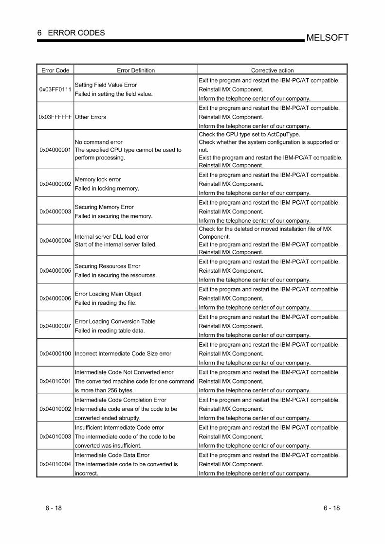
6 - 18 6 - 18
MELSOFT6 ERROR CODES
Error Code Error Definition Corrective action
0x03FF0111 Setting Field Value Error Failed in setting the field value.
Exit the program and restart the IBM-PC/AT compatible. Reinstall MX Component. Inform the telephone center of our company.
0x03FFFFFF Other Errors Exit the program and restart the IBM-PC/AT compatible. Reinstall MX Component. Inform the telephone center of our company.
0x04000001 No command error The specified CPU type cannot be used to perform processing.
Check the CPU type set to ActCpuType. Check whether the system configuration is supported or not. Exist the program and restart the IBM-PC/AT compatible. Reinstall MX Component.
0x04000002 Memory lock error Failed in locking memory.
Exit the program and restart the IBM-PC/AT compatible. Reinstall MX Component. Inform the telephone center of our company.
0x04000003 Securing Memory Error Failed in securing the memory.
Exit the program and restart the IBM-PC/AT compatible. Reinstall MX Component. Inform the telephone center of our company.
0x04000004 Internal server DLL load error Start of the internal server failed.
Check for the deleted or moved installation file of MX Component. Exit the program and restart the IBM-PC/AT compatible. Reinstall MX Component.
0x04000005 Securing Resources Error Failed in securing the resources.
Exit the program and restart the IBM-PC/AT compatible. Reinstall MX Component. Inform the telephone center of our company.
0x04000006 Error Loading Main Object Failed in reading the file.
Exit the program and restart the IBM-PC/AT compatible. Reinstall MX Component. Inform the telephone center of our company.
0x04000007 Error Loading Conversion Table Failed in reading table data.
Exit the program and restart the IBM-PC/AT compatible. Reinstall MX Component. Inform the telephone center of our company.
0x04000100 Incorrect Intermediate Code Size error Exit the program and restart the IBM-PC/AT compatible. Reinstall MX Component. Inform the telephone center of our company.
0x04010001 Intermediate Code Not Converted error The converted machine code for one command is more than 256 bytes.
Exit the program and restart the IBM-PC/AT compatible. Reinstall MX Component. Inform the telephone center of our company.
0x04010002 Intermediate Code Completion Error Intermediate code area of the code to be converted ended abruptly.
Exit the program and restart the IBM-PC/AT compatible. Reinstall MX Component. Inform the telephone center of our company.
0x04010003 Insufficient Intermediate Code error The intermediate code of the code to be converted was insufficient.
Exit the program and restart the IBM-PC/AT compatible. Reinstall MX Component. Inform the telephone center of our company.
0x04010004 Intermediate Code Data Error The intermediate code to be converted is incorrect.
Exit the program and restart the IBM-PC/AT compatible. Reinstall MX Component. Inform the telephone center of our company.

6 - 19 6 - 19
MELSOFT6 ERROR CODES
Error Code Error Definition Corrective action
0x04010005 Intermediate Code Structure Error The number of steps in the intermediate code is incorrect.
Exit the program and restart the IBM-PC/AT compatible. Reinstall MX Component. Inform the telephone center of our company.
0x04010006 Error in Number of Steps The number of steps in comment intermediate code is incorrect.
Exit the program and restart the IBM-PC/AT compatible. Reinstall MX Component. Inform the telephone center of our company.
0x04010007
Insufficient Storage Space for Machine Code error The storage space for machine code is insufficient.
Exit the program and restart the IBM-PC/AT compatible. Reinstall MX Component. Inform the telephone center of our company.
0x04010008 Other Errors (Other errors generated during the conversion of Intermediate code to machine code.)
Exit the program and restart the IBM-PC/AT compatible. Reinstall MX Component. Inform the telephone center of our company.
0x04011001 Machine Code Not Converted error The converted intermediate code for one command is more than 256 bytes.
Exit the program and restart the IBM-PC/AT compatible. Reinstall MX Component. Inform the telephone center of our company.
0x04011002 Machine Code Completion Error The machine code area to be converted ended abruptly.
Exit the program and restart the IBM-PC/AT compatible. Reinstall MX Component. Inform the telephone center of our company.
0x04011003 Abnormal Machine Code Could not convert since the machine code to be converted was abnormal.
Exit the program and restart the IBM-PC/AT compatible. Reinstall MX Component. Inform the telephone center of our company.
0x04011004
Insufficient Storage Space for Intermediate Code error The storage area for intermediate code is insufficient.
Exit the program and restart the IBM-PC/AT compatible. Reinstall MX Component. Inform the telephone center of our company.
0x04011005 Other Errors Other errors generated while converting machine code to Intermediate code.
Exit the program and restart the IBM-PC/AT compatible. Reinstall MX Component. Inform the telephone center of our company.
0x04020001 Text Code Not Converted error The converted intermediate code for one command is more than 256 bytes.
Exit the program and restart the IBM-PC/AT compatible. Reinstall MX Component. Inform the telephone center of our company.
0x04020002 No Input error The input list code is insufficient.
Exit the program and restart the IBM-PC/AT compatible. Reinstall MX Component. Inform the telephone center of our company.
0x04020003 Command Error The command name of list code to be converted is incorrect.
Exit the program and restart the IBM-PC/AT compatible. Reinstall MX Component. Inform the telephone center of our company.
0x04020004 Device Error The device name of list code to be converted is incorrect.
Exit the program and restart the IBM-PC/AT compatible. Reinstall MX Component. Inform the telephone center of our company.
0x04020005 Device Number Error The device number of the list code to be converted is out of range.
Exit the program and restart the IBM-PC/AT compatible. Reinstall MX Component. Inform the telephone center of our company.
0x04020006 Conversion Error The list code to be converted conversion could not be identified.
Exit the program and restart the IBM-PC/AT compatible. Reinstall MX Component. Inform the telephone center of our company.

6 - 20 6 - 20
MELSOFT6 ERROR CODES
Error Code Error Definition Corrective action
0x04020007 Text Data Error The list code to be converted is incorrect.
Exit the program and restart the IBM-PC/AT compatible. Reinstall MX Component. Inform the telephone center of our company.
0x04020008 Error in SFC Operation Output The output command of SFC operation is incorrect.
Exit the program and restart the IBM-PC/AT compatible. Reinstall MX Component. Inform the telephone center of our company.
0x04020009 SFC Shift Condition Error SFC shift condition command is incorrect.
Exit the program and restart the IBM-PC/AT compatible. Reinstall MX Component. Inform the telephone center of our company.
0x0402000A Error in Statements between lines The statements entered between lines are incorrect.
Exit the program and restart the IBM-PC/AT compatible. Reinstall MX Component. Inform the telephone center of our company.
0x0402000B P.I Statement Error The P.I statement entered is incorrect.
Exit the program and restart the IBM-PC/AT compatible. Reinstall MX Component. Inform the telephone center of our company.
0x0402000C Note Error The Note entered is incorrect.
Exit the program and restart the IBM-PC/AT compatible. Reinstall MX Component. Inform the telephone center of our company.
0x0402000D Comment Error The comment entered is incorrect.
Exit the program and restart the IBM-PC/AT compatible. Reinstall MX Component. Inform the telephone center of our company.
0x0402000E Other Errors (Other errors generated during the conversion of list to Intermediate code)
Exit the program and restart the IBM-PC/AT compatible. Reinstall MX Component. Inform the telephone center of our company.
0x04021001 Intermediate Code Not Converted error The converted list code for one command has exceeded 256 bytes.
Exit the program and restart the IBM-PC/AT compatible. Reinstall MX Component. Inform the telephone center of our company.
0x04021002 Intermediate Code Area Full error Intermediate code area to be converted is full.
Exit the program and restart the IBM-PC/AT compatible. Reinstall MX Component. Inform the telephone center of our company.
0x04021003 Command Error The command specified by the intermediate code to be converted is incorrect.
Exit the program and restart the IBM-PC/AT compatible. Reinstall MX Component. Inform the telephone center of our company.
0x04021004 Device Error The device specified in the intermediate code to be converted is incorrect.
Exit the program and restart the IBM-PC/AT compatible. Reinstall MX Component. Inform the telephone center of our company.
0x04021005 Intermediate Code Error The structure of intermediate code to be converted is incorrect.
Exit the program and restart the IBM-PC/AT compatible. Reinstall MX Component. Inform the telephone center of our company.
0x04021006 Insufficient List Storage Space error The space for storing the converted list code is insufficient.
Exit the program and restart the IBM-PC/AT compatible. Reinstall MX Component. Inform the telephone center of our company.
0x04021007 Other Errors (Other errors generated during the conversion of intermediate code to list)
Exit the program and restart the IBM-PC/AT compatible. Reinstall MX Component. Inform the telephone center of our company.

6 - 21 6 - 21
MELSOFT6 ERROR CODES
Error Code Error Definition Corrective action
0x04030001 Not Converted error The storage space for converted intermediate code is insufficient.
Exit the program and restart the IBM-PC/AT compatible. Reinstall MX Component. Inform the telephone center of our company.
0x04030002 Bad Circuit Creation error The character memory circuit is not completed in a sequence.
Exit the program and restart the IBM-PC/AT compatible. Reinstall MX Component. Inform the telephone center of our company.
0x04030003 Specified Circuit Size Exceeded Specified circuit size is too big.
Exit the program and restart the IBM-PC/AT compatible. Reinstall MX Component. Inform the telephone center of our company.
0x04030004
Incorrect Return Circuit error There is no consistency before and after the return circuit. The setting for the return circuit is too high.
Exit the program and restart the IBM-PC/AT compatible. Reinstall MX Component. Inform the telephone center of our company.
0x04030005 Other Errors (Other errors generated while converting from Character Memory to Intermediate Code)
Exit the program and restart the IBM-PC/AT compatible. Reinstall MX Component. Inform the telephone center of our company.
0x04031001 Not Converted error The size (vertical/horizontal) of the character memory specified is incorrect.
Exit the program and restart the IBM-PC/AT compatible. Reinstall MX Component. Inform the telephone center of our company.
0x04031002 Abnormal Command Code error The command intermediate code to be converted is incorrect.
Exit the program and restart the IBM-PC/AT compatible. Reinstall MX Component. Inform the telephone center of our company.
0x04031003 Bad Circuit Creation error Could not be converted to Sequence Circuit. There is no END command.
Exit the program and restart the IBM-PC/AT compatible. Reinstall MX Component. Inform the telephone center of our company.
0x04031004 Specified Circuit Size exceeded error Specified circuit size is too big.
Exit the program and restart the IBM-PC/AT compatible. Reinstall MX Component. Inform the telephone center of our company.
0x04031005 Fatal Error Fatal Error has occured.
Exit the program and restart the IBM-PC/AT compatible. Reinstall MX Component. Inform the telephone center of our company.
0x04031006 Insufficient number of storage blocks error The space to store the converted character memory circuit blocks is not sufficient.
Exit the program and restart the IBM-PC/AT compatible. Reinstall MX Component. Inform the telephone center of our company.
0x04031007 Circuit Block Search Error Data is broken off in the circuit block.
Exit the program and restart the IBM-PC/AT compatible. Reinstall MX Component. Inform the telephone center of our company.
0x04031008 Other Errors (Other errors generated during the conversion of intermediate code to character memory)
Exit the program and restart the IBM-PC/AT compatible. Reinstall MX Component. Inform the telephone center of our company.
0x04040001 CAD Data Error There is no CAD data to be converted. The CAD data format is incorrect.
Exit the program and restart the IBM-PC/AT compatible. Reinstall MX Component. Inform the telephone center of our company.
0x04040002 Output Data Error The input CAD data type and the output CAD data type are not matching.
Exit the program and restart the IBM-PC/AT compatible. Reinstall MX Component. Inform the telephone center of our company.

6 - 22 6 - 22
MELSOFT6 ERROR CODES
Error Code Error Definition Corrective action
0x04040003 Library Load Error Failed to load the library.
Exit the program and restart the IBM-PC/AT compatible. Reinstall MX Component. Inform the telephone center of our company.
0x04040004 Storage Space Secure Error The space secured to store the converted data is not sufficient.
Exit the program and restart the IBM-PC/AT compatible. Reinstall MX Component. Inform the telephone center of our company.
0x04040005 No END Command error There is no END command in the CAD data to be converted.
Exit the program and restart the IBM-PC/AT compatible. Reinstall MX Component. Inform the telephone center of our company.
0x04040006 Abnormal Command Code There is abnormal command code in the CAD data to be converted.
Exit the program and restart the IBM-PC/AT compatible. Reinstall MX Component. Inform the telephone center of our company.
0x04040007 Device No. Error The device number is out of range.
Exit the program and restart the IBM-PC/AT compatible. Reinstall MX Component. Inform the telephone center of our company.
0x04040008 Step No. Error The step number is out of range.
Exit the program and restart the IBM-PC/AT compatible. Reinstall MX Component. Inform the telephone center of our company.
0x04040009 The specified circuit size exceeded error. 1 circuit block is too big.
Exit the program and restart the IBM-PC/AT compatible. Reinstall MX Component. Inform the telephone center of our company.
0x0404000A Return Circuit Error The return circuit is incorrect.
Exit the program and restart the IBM-PC/AT compatible. Reinstall MX Component. Inform the telephone center of our company.
0x0404000B Bad Circuit Creation error The circuit data is incorrect.
Exit the program and restart the IBM-PC/AT compatible. Reinstall MX Component. Inform the telephone center of our company.
0x0404000C SFC Data Error The SFC data to be converted is incorrect.
Exit the program and restart the IBM-PC/AT compatible. Reinstall MX Component. Inform the telephone center of our company.
0x0404000D List Data Error The list data to be converted is incorrect.
Exit the program and restart the IBM-PC/AT compatible. Reinstall MX Component. Inform the telephone center of our company.
0x0404000E Comment Data Error The comment data to be converted is incorrect.
Exit the program and restart the IBM-PC/AT compatible. Reinstall MX Component. Inform the telephone center of our company.
0x0404000F Statement Error The statement data to be converted is incorrect.
Exit the program and restart the IBM-PC/AT compatible. Reinstall MX Component. Inform the telephone center of our company.
0x04040010 Other Errors (Other errors generated during the conversion of CAD code to Intermediate code.)
Exit the program and restart the IBM-PC/AT compatible. Reinstall MX Component. Inform the telephone center of our company.
0x04041001 Intermediate Code Data Error There is no intermediate code to be converted. The format of the intermediate code is incorrect.
Exit the program and restart the IBM-PC/AT compatible. Reinstall MX Component. Inform the telephone center of our company.

6 - 23 6 - 23
MELSOFT6 ERROR CODES
Error Code Error Definition Corrective action
0x04041002 CAD Data Type Error The input CAD data type and the output CAD data type are not matching.
Exit the program and restart the IBM-PC/AT compatible. Reinstall MX Component. Inform the telephone center of our company.
0x04041003 Library Error Failed to load the library.
Exit the program and restart the IBM-PC/AT compatible. Reinstall MX Component. Inform the telephone center of our company.
0x04041004 Insufficient Input Data error Data to be converted is insufficient.
Exit the program and restart the IBM-PC/AT compatible. Reinstall MX Component. Inform the telephone center of our company.
0x04041005 Insufficient Storage Space error There is not enough space to store the CAD data to be converted.
Exit the program and restart the IBM-PC/AT compatible. Reinstall MX Component. Inform the telephone center of our company.
0x04041006 No END Command error There is no END command in the CAD data to be converted.
Exit the program and restart the IBM-PC/AT compatible. Reinstall MX Component. Inform the telephone center of our company.
0x04041007 Abnormal Command Code There is abnormal command code in the CAD data to be converted.
Exit the program and restart the IBM-PC/AT compatible. Reinstall MX Component. Inform the telephone center of our company.
0x04041008 Device No. Error The device number is out of range.
Exit the program and restart the IBM-PC/AT compatible. Reinstall MX Component. Inform the telephone center of our company.
0x04041009 Step No. Error The step number is out of range.
Exit the program and restart the IBM-PC/AT compatible. Reinstall MX Component. Inform the telephone center of our company.
0x0404100A The specified circuit size exceeded error. 1 circuit block is too big.
Exit the program and restart the IBM-PC/AT compatible. Reinstall MX Component. Inform the telephone center of our company.
0x0404100B Return Circuit Error The return circuit is incorrect.
Exit the program and restart the IBM-PC/AT compatible. Reinstall MX Component. Inform the telephone center of our company.
0x0404100C Bad Circuit Creation error The circuit data is incorrect.
Exit the program and restart the IBM-PC/AT compatible. Reinstall MX Component. Inform the telephone center of our company.
0x0404100D SFC Data Error The SFC data to be converted is incorrect.
Exit the program and restart the IBM-PC/AT compatible. Reinstall MX Component. Inform the telephone center of our company.
0x0404100E List Data Error The list data to be converted is incorrect.
Exit the program and restart the IBM-PC/AT compatible. Reinstall MX Component. Inform the telephone center of our company.
0x0404100F Comment Data Error The comment data to be converted is incorrect.
Exit the program and restart the IBM-PC/AT compatible. Reinstall MX Component. Inform the telephone center of our company.
0x04041010 Statement Error The statement data to be converted is incorrect.
Exit the program and restart the IBM-PC/AT compatible. Reinstall MX Component. Inform the telephone center of our company.

6 - 24 6 - 24
MELSOFT6 ERROR CODES
Error Code Error Definition Corrective action
0x04041011 Other Errors (Other errors generated during the conversion of Intermediate code to CAD code.)
Exit the program and restart the IBM-PC/AT compatible. Reinstall MX Component. Inform the telephone center of our company.
0x040A0001 Insufficient Intermediate Code Storage Space The space to store the data after conversion is insufficient.
Exit the program and restart the IBM-PC/AT compatible. Reinstall MX Component. Inform the telephone center of our company.
0x040A0002 The space to store addition SFC information is not sufficient
Exit the program and restart the IBM-PC/AT compatible. Reinstall MX Component. Inform the telephone center of our company.
0x040A0003 Conversion Error Exit the program and restart the IBM-PC/AT compatible. Reinstall MX Component. Inform the telephone center of our company.
0x040A0004 Non-SFC Program Error Exit the program and restart the IBM-PC/AT compatible. Reinstall MX Component. Inform the telephone center of our company.
0x040A1001 Step Not Used / No Output error Exit the program and restart the IBM-PC/AT compatible. Reinstall MX Component. Inform the telephone center of our company.
0x040A1002 Step No out of range error Exit the program and restart the IBM-PC/AT compatible. Reinstall MX Component. Inform the telephone center of our company.
0x040A1003 Step Not Used / No Output error Exit the program and restart the IBM-PC/AT compatible. Reinstall MX Component. Inform the telephone center of our company.
0x040A1004 Transition No out of range. Exit the program and restart the IBM-PC/AT compatible. Reinstall MX Component. Inform the telephone center of our company.
0x040A1005 Maximum Number Exceeded error Exit the program and restart the IBM-PC/AT compatible. Reinstall MX Component. Inform the telephone center of our company.
0x040A1006 Microcontroller Program space Error Exit the program and restart the IBM-PC/AT compatible. Reinstall MX Component. Inform the telephone center of our company.
0x040A1007 Non-SFC Program Error Exit the program and restart the IBM-PC/AT compatible. Reinstall MX Component. Inform the telephone center of our company.
0x040B0001 Insufficient Intermediate Code Storage Space. The space to store the data after conversion is insufficient.
Exit the program and restart the IBM-PC/AT compatible. Reinstall MX Component. Inform the telephone center of our company.
0x040B0002 Conversion Error Exit the program and restart the IBM-PC/AT compatible. Reinstall MX Component. Inform the telephone center of our company.
0x040B1001 Failed in creating Step Start position table Exit the program and restart the IBM-PC/AT compatible. Reinstall MX Component. Inform the telephone center of our company.
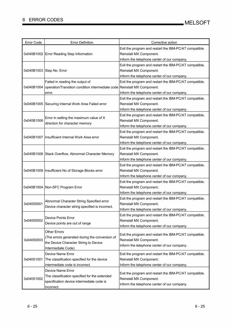
6 - 25 6 - 25
MELSOFT6 ERROR CODES
Error Code Error Definition Corrective action
0x040B1002 Error Reading Step Information Exit the program and restart the IBM-PC/AT compatible. Reinstall MX Component. Inform the telephone center of our company.
0x040B1003 Step No. Error Exit the program and restart the IBM-PC/AT compatible. Reinstall MX Component. Inform the telephone center of our company.
0x040B1004 Failed in reading the output of operation/Transition condition intermediate code error.
Exit the program and restart the IBM-PC/AT compatible. Reinstall MX Component. Inform the telephone center of our company.
0x040B1005 Securing Internal Work Area Failed error Exit the program and restart the IBM-PC/AT compatible. Reinstall MX Component. Inform the telephone center of our company.
0x040B1006 Error in setting the maximum value of X direction for character memory
Exit the program and restart the IBM-PC/AT compatible. Reinstall MX Component. Inform the telephone center of our company.
0x040B1007 Insufficient Internal Work Area error Exit the program and restart the IBM-PC/AT compatible. Reinstall MX Component. Inform the telephone center of our company.
0x040B1008 Stack Overflow, Abnormal Character Memory Exit the program and restart the IBM-PC/AT compatible. Reinstall MX Component. Inform the telephone center of our company.
0x040B1009 Insufficient No of Storage Blocks error Exit the program and restart the IBM-PC/AT compatible. Reinstall MX Component. Inform the telephone center of our company.
0x040B100A Non-SFC Program Error Exit the program and restart the IBM-PC/AT compatible. Reinstall MX Component. Inform the telephone center of our company.
0x04050001 Abnormal Character String Specified error Device character string specified is incorrect.
Exit the program and restart the IBM-PC/AT compatible. Reinstall MX Component. Inform the telephone center of our company.
0x04050002 Device Points Error Device points are out of range
Exit the program and restart the IBM-PC/AT compatible. Reinstall MX Component. Inform the telephone center of our company.
0x04050003
Other Errors (The errors generated during the conversion of the Device Character String to Device Intermediate Code)
Exit the program and restart the IBM-PC/AT compatible. Reinstall MX Component. Inform the telephone center of our company.
0x04051001 Device Name Error The classification specified for the device intermediate code is incorrect.
Exit the program and restart the IBM-PC/AT compatible. Reinstall MX Component. Inform the telephone center of our company.
0x04051002
Device Name Error The classification specified for the extended specification device intermediate code is incorrect.
Exit the program and restart the IBM-PC/AT compatible. Reinstall MX Component. Inform the telephone center of our company.

6 - 26 6 - 26
MELSOFT6 ERROR CODES
Error Code Error Definition Corrective action
0x04051003
Other Errors (The errors generated during the conversion of the Device Intermediate Code to Device Character String)
Exit the program and restart the IBM-PC/AT compatible. Reinstall MX Component. Inform the telephone center of our company.
0x04052001 Abnormal Character String Specified error Device character string specified is incorrect.
Exit the program and restart the IBM-PC/AT compatible. Reinstall MX Component. Inform the telephone center of our company.
0x04052002 Device Points Error Device points are out of range.
Exit the program and restart the IBM-PC/AT compatible. Reinstall MX Component. Inform the telephone center of our company.
0x04052003
Other Errors (The errors generated during the conversion of the Device Character String to Device Representation Code)
Exit the program and restart the IBM-PC/AT compatible. Reinstall MX Component. Inform the telephone center of our company.
0x04053001 Device Representation Error The classification specified for the device intermediate code is incorrect.
Exit the program and restart the IBM-PC/AT compatible. Reinstall MX Component. Inform the telephone center of our company.
0x04053002
Device Representation Error The classification specified for the extended specification device intermediate code is incorrect.
Exit the program and restart the IBM-PC/AT compatible. Reinstall MX Component. Inform the telephone center of our company.
0x04053003 Device Representation Error The rectification part specified for the device is incorrect.
Exit the program and restart the IBM-PC/AT compatible. Reinstall MX Component. Inform the telephone center of our company.
0x04053004 Device Representation Error The rectification part specified for the extended device is incorrect.
Exit the program and restart the IBM-PC/AT compatible. Reinstall MX Component. Inform the telephone center of our company.
0x04053005
Other Errors (The errors generated during the conversion of the Device Representation Code to Device Character String)
Exit the program and restart the IBM-PC/AT compatible. Reinstall MX Component. Inform the telephone center of our company.
0x04064001 Abnormal Device Intermediate Code error The intermediate code for the device is incorrect.
Exit the program and restart the IBM-PC/AT compatible. Reinstall MX Component. Inform the telephone center of our company.
0x04064002
Other Errors (Other errors generated during the conversion of the Intermediate code for the Device to Device Name)
Exit the program and restart the IBM-PC/AT compatible. Reinstall MX Component. Inform the telephone center of our company.
0x04065001 Abnormal Device Name error The classification specified for the intermediate code of the device is incorrect.
Exit the program and restart the IBM-PC/AT compatible. Reinstall MX Component. Inform the telephone center of our company.
0x04065002 Abnormal Device Name error The classification for the intermediate code of the extended specification device is incorrect.
Exit the program and restart the IBM-PC/AT compatible. Reinstall MX Component. Inform the telephone center of our company.

6 - 27 6 - 27
MELSOFT6 ERROR CODES
Error Code Error Definition Corrective action
0x04065003 Other Errors (Other errors generated during the conversion of the device name to Intermediate code)
Exit the program and restart the IBM-PC/AT compatible. Reinstall MX Component. Inform the telephone center of our company.
0x04066001 Device Intermediate Code Error The intermediate code for the device is incorrect.
Exit the program and restart the IBM-PC/AT compatible. Reinstall MX Component. Inform the telephone center of our company.
0x04066002
Other Errors (Other errors generated during the conversion of the device intermediate code to device representation code.)
Exit the program and restart the IBM-PC/AT compatible. Reinstall MX Component. Inform the telephone center of our company.
0x04067001 Device Representation Error The classification specified for the intermediate code of the device is incorrect.
Exit the program and restart the IBM-PC/AT compatible. Reinstall MX Component. Inform the telephone center of our company.
0x04067002 Device Representation Error The classification for the intermediate code of the extended specification device is incorrect.
Exit the program and restart the IBM-PC/AT compatible. Reinstall MX Component. Inform the telephone center of our company.
0x04067003 Device Representation Error The rectification part specified for the device is incorrect.
Exit the program and restart the IBM-PC/AT compatible. Reinstall MX Component. Inform the telephone center of our company.
0x04067004 Device Representation Error The rectification part specified for the extended device is incorrect.
Exit the program and restart the IBM-PC/AT compatible. Reinstall MX Component. Inform the telephone center of our company.
0x04067005
Other Errors (Other errors generated during the conversion of device representation code to the device intermediate code)
Exit the program and restart the IBM-PC/AT compatible. Reinstall MX Component. Inform the telephone center of our company.
0x04070001 Common Data Conversion Error The input data of the device comment conversion is incorrect.
Exit the program and restart the IBM-PC/AT compatible. Reinstall MX Component. Inform the telephone center of our company.
0x04070002 Insufficient Common Data The data to be converted is insufficient.
Exit the program and restart the IBM-PC/AT compatible. Reinstall MX Component. Inform the telephone center of our company.
0x04070003 Insufficient Storage Area The area where the conversion data is stored is insufficient.
Exit the program and restart the IBM-PC/AT compatible. Reinstall MX Component. Inform the telephone center of our company.
0x04071001 Error in PLC Data Conversion The input data of the device comment conversion is incorrect.
Exit the program and restart the IBM-PC/AT compatible. Reinstall MX Component. Inform the telephone center of our company.
0x04071002 Insufficient PLC Data error The data to be converted is insufficient.
Exit the program and restart the IBM-PC/AT compatible. Reinstall MX Component. Inform the telephone center of our company.
0x04071003 Insufficient Storage Area The area where the conversion data is stored is insufficient.
Exit the program and restart the IBM-PC/AT compatible. Reinstall MX Component. Inform the telephone center of our company.
0x04072001 Open Error Failed in creating conversion object
Exit the program and restart the IBM-PC/AT compatible. Reinstall MX Component. Inform the telephone center of our company.
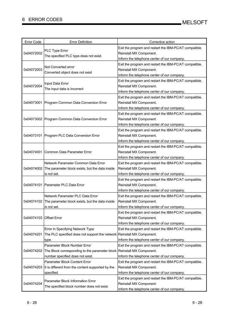
6 - 28 6 - 28
MELSOFT6 ERROR CODES
Error Code Error Definition Corrective action
0x04072002 PLC Type Error The specified PLC type does not exist.
Exit the program and restart the IBM-PC/AT compatible. Reinstall MX Component. Inform the telephone center of our company.
0x04072003 Not Converted error Converted object does not exist
Exit the program and restart the IBM-PC/AT compatible. Reinstall MX Component. Inform the telephone center of our company.
0x04072004 Input Data Error The input data is incorrect
Exit the program and restart the IBM-PC/AT compatible. Reinstall MX Component. Inform the telephone center of our company.
0x04073001 Program Common Data Conversion Error Exit the program and restart the IBM-PC/AT compatible. Reinstall MX Component. Inform the telephone center of our company.
0x04073002 Program Common Data Conversion Error Exit the program and restart the IBM-PC/AT compatible. Reinstall MX Component. Inform the telephone center of our company.
0x04073101 Program PLC Data Conversion Error Exit the program and restart the IBM-PC/AT compatible. Reinstall MX Component. Inform the telephone center of our company.
0x04074001 Common Data Parameter Error Exit the program and restart the IBM-PC/AT compatible. Reinstall MX Component. Inform the telephone center of our company.
0x04074002 Network Parameter Common Data Error The parameter block exists, but the data inside is not set.
Exit the program and restart the IBM-PC/AT compatible. Reinstall MX Component. Inform the telephone center of our company.
0x04074101 Parameter PLC Data Error Exit the program and restart the IBM-PC/AT compatible. Reinstall MX Component. Inform the telephone center of our company.
0x04074102 Network Parameter PLC Data Error The parameter block exists, but the data inside is not set.
Exit the program and restart the IBM-PC/AT compatible. Reinstall MX Component. Inform the telephone center of our company.
0x04074103 Offset Error Exit the program and restart the IBM-PC/AT compatible. Reinstall MX Component. Inform the telephone center of our company.
0x04074201 Error in Specifying Network Type The PLC specified does not support the network type.
Exit the program and restart the IBM-PC/AT compatible. Reinstall MX Component. Inform the telephone center of our company.
0x04074202 Parameter Block Number Error The Block corresponding to the parameter block number specified does not exist.
Exit the program and restart the IBM-PC/AT compatible. Reinstall MX Component. Inform the telephone center of our company.
0x04074203 Parameter Block Content Error It is different from the content supported by the specified.
Exit the program and restart the IBM-PC/AT compatible. Reinstall MX Component. Inform the telephone center of our company.
0x04074204 Parameter Block Information Error The specified block number does not exist.
Exit the program and restart the IBM-PC/AT compatible. Reinstall MX Component. Inform the telephone center of our company.

6 - 29 6 - 29
MELSOFT6 ERROR CODES
Error Code Error Definition Corrective action
0x04074205 Default Parameter Block is Abnormal The specified block number does not exist.
Exit the program and restart the IBM-PC/AT compatible. Reinstall MX Component. Inform the telephone center of our company.
0x04074301 Error in Conversion of the Common Parameter Block
Exit the program and restart the IBM-PC/AT compatible. Reinstall MX Component. Inform the telephone center of our company.
0x04074302 Error in Common Parameter Block No. 1001 The value of the RUN-PAUSE settings existence flag is incorrect.
Exit the program and restart the IBM-PC/AT compatible. Reinstall MX Component. Inform the telephone center of our company.
0x04074303 Error in Common Parameter Block No. 1003 Exit the program and restart the IBM-PC/AT compatible. Reinstall MX Component. Inform the telephone center of our company.
0x04074304 Error in Common Parameter Block No. 1008 Exit the program and restart the IBM-PC/AT compatible. Reinstall MX Component. Inform the telephone center of our company.
0x04074305 Error in Common Parameter Block No. 1100 Exit the program and restart the IBM-PC/AT compatible. Reinstall MX Component. Inform the telephone center of our company.
0x04074306 Error in Common Parameter Block No. 2001 The device intermediate code specified does not exist.
Exit the program and restart the IBM-PC/AT compatible. Reinstall MX Component. Inform the telephone center of our company.
0x04074307 Error in Common Parameter Block No. 3000 Exit the program and restart the IBM-PC/AT compatible. Reinstall MX Component. Inform the telephone center of our company.
0x04074308 Error in Common Parameter Block No. 3002 Exit the program and restart the IBM-PC/AT compatible. Reinstall MX Component. Inform the telephone center of our company.
0x04074309 Error in Common Parameter Block No. 3004 The settings for the annunciator display mode is incorrect.
Exit the program and restart the IBM-PC/AT compatible. Reinstall MX Component. Inform the telephone center of our company.
0x0407430A Error in Common Parameter Block No. 4000 I/O Allotment Data is not created.
Exit the program and restart the IBM-PC/AT compatible. Reinstall MX Component. Inform the telephone center of our company.
0x0407430B Error in Common Parameter Block No. 5000 The specified network is not supported.
Exit the program and restart the IBM-PC/AT compatible. Reinstall MX Component. Inform the telephone center of our company.
0x0407430C Error in Common Parameter Block No. 5001 Valid unit No is not set while accessing other exchange.
Exit the program and restart the IBM-PC/AT compatible. Reinstall MX Component. Inform the telephone center of our company.
0x0407430D Error in Common Parameter Block No. 5002 Exit the program and restart the IBM-PC/AT compatible. Reinstall MX Component. Inform the telephone center of our company.
0x0407430E Error in Common Parameter Block No. 5003 Exit the program and restart the IBM-PC/AT compatible. Reinstall MX Component. Inform the telephone center of our company.

6 - 30 6 - 30
MELSOFT6 ERROR CODES
Error Code Error Definition Corrective action
0x0407430F Error in Common Parameter Block No. 5NM0 Exit the program and restart the IBM-PC/AT compatible. Reinstall MX Component. Inform the telephone center of our company.
0x04074310 Error in Common Parameter Block No. 5NM1 Exit the program and restart the IBM-PC/AT compatible. Reinstall MX Component. Inform the telephone center of our company.
0x04074311 Error in Common Parameter Block No. 5NM2 Exit the program and restart the IBM-PC/AT compatible. Reinstall MX Component. Inform the telephone center of our company.
0x04074312 Error in Common Parameter Block No. 5NM3 Exit the program and restart the IBM-PC/AT compatible. Reinstall MX Component. Inform the telephone center of our company.
0x04074313 Error in Common Parameter Block No. 6000 Exit the program and restart the IBM-PC/AT compatible. Reinstall MX Component. Inform the telephone center of our company.
0x04074314 Error in Common Parameter Block No. FF18 Link parameter Capacity is not set.
Exit the program and restart the IBM-PC/AT compatible. Reinstall MX Component. Inform the telephone center of our company.
0x04074315 Error in Common Parameter Block No. FF25 Calculation circuit check is not set.
Exit the program and restart the IBM-PC/AT compatible. Reinstall MX Component. Inform the telephone center of our company.
0x04074316 Error in Common Parameter Block No. FF30 Sampling Trace Data is not created.
Exit the program and restart the IBM-PC/AT compatible. Reinstall MX Component. Inform the telephone center of our company.
0x04074317 Error in Common Parameter Block No. FF31 Status latch data is not created.
Exit the program and restart the IBM-PC/AT compatible. Reinstall MX Component. Inform the telephone center of our company.
0x04074318 Error in Common Parameter Block No. FF42 Timer processing points are not set.
Exit the program and restart the IBM-PC/AT compatible. Reinstall MX Component. Inform the telephone center of our company.
0x04074319 Error in Common Parameter Block No. FF30 Setting value device for specified extended timer does not exist.
Exit the program and restart the IBM-PC/AT compatible. Reinstall MX Component. Inform the telephone center of our company.
0x0407431A Error in Common Parameter Block No. FF44 Exit the program and restart the IBM-PC/AT compatible. Reinstall MX Component. Inform the telephone center of our company.
0x0407431B Error in Common Parameter Block No. FF45 Exit the program and restart the IBM-PC/AT compatible. Reinstall MX Component. Inform the telephone center of our company.
0x0407431C Error in Common Parameter Block No. FF60 Terminal Settings are not set.
Exit the program and restart the IBM-PC/AT compatible. Reinstall MX Component. Inform the telephone center of our company.
0x0407431D Error in Common Parameter Block No. FF70 User Release area is not set.
Exit the program and restart the IBM-PC/AT compatible. Reinstall MX Component. Inform the telephone center of our company.

6 - 31 6 - 31
MELSOFT6 ERROR CODES
Error Code Error Definition Corrective action
0x04074401 Error in Conversion of PLC Parameter Block Exit the program and restart the IBM-PC/AT compatible. Reinstall MX Component. Inform the telephone center of our company.
0x04074402 Error in PLC Parameter Block No.1001 Exit the program and restart the IBM-PC/AT compatible. Reinstall MX Component. Inform the telephone center of our company.
0x04074403 Error in PLC Parameter Block No.1003 Exit the program and restart the IBM-PC/AT compatible. Reinstall MX Component. Inform the telephone center of our company.
0x04074404 Error in PLC Parameter Block No.1008 Exit the program and restart the IBM-PC/AT compatible. Reinstall MX Component. Inform the telephone center of our company.
0x04074405 Error in PLC Parameter Block No.1100 Exit the program and restart the IBM-PC/AT compatible. Reinstall MX Component. Inform the telephone center of our company.
0x04074406 Error in PLC Parameter Block No.2001 Exit the program and restart the IBM-PC/AT compatible. Reinstall MX Component. Inform the telephone center of our company.
0x04074407 Error in PLC Parameter Block No.3000 Exit the program and restart the IBM-PC/AT compatible. Reinstall MX Component. Inform the telephone center of our company.
0x04074408 Error in PLC Parameter Block No.3002 Exit the program and restart the IBM-PC/AT compatible. Reinstall MX Component. Inform the telephone center of our company.
0x04074409 Error in PLC Parameter Block No.3004 Exit the program and restart the IBM-PC/AT compatible. Reinstall MX Component. Inform the telephone center of our company.
0x0407440A Error in PLC Parameter Block No.4000 Exit the program and restart the IBM-PC/AT compatible. Reinstall MX Component. Inform the telephone center of our company.
0x0407440B Error in PLC Parameter Block No.5000 The specified network type is not supported.
Exit the program and restart the IBM-PC/AT compatible. Reinstall MX Component. Inform the telephone center of our company.
0x0407440C Error in PLC Parameter Block No.5001 Exit the program and restart the IBM-PC/AT compatible. Reinstall MX Component. Inform the telephone center of our company.
0x0407440D Error in PLC Parameter Block No.5002 Exit the program and restart the IBM-PC/AT compatible. Reinstall MX Component. Inform the telephone center of our company.
0x0407440E Error in PLC Parameter Block No.5003 Exit the program and restart the IBM-PC/AT compatible. Reinstall MX Component. Inform the telephone center of our company.
0x0407440F Error in PLC Parameter Block No. 5NM0 The specified network type is not supported.
Exit the program and restart the IBM-PC/AT compatible. Reinstall MX Component. Inform the telephone center of our company.

6 - 32 6 - 32
MELSOFT6 ERROR CODES
Error Code Error Definition Corrective action
0x04074410 Error in PLC Parameter Block No. 5NM1 Exit the program and restart the IBM-PC/AT compatible. Reinstall MX Component. Inform the telephone center of our company.
0x04074411 Error in PLC Parameter Block No. 5NM2 The specified network type is not supported.
Exit the program and restart the IBM-PC/AT compatible. Reinstall MX Component. Inform the telephone center of our company.
0x04074412 Error in PLC Parameter Block No. 5NM3 Exit the program and restart the IBM-PC/AT compatible. Reinstall MX Component. Inform the telephone center of our company.
0x04074413 Error in PLC Parameter Block No. 6000 Exit the program and restart the IBM-PC/AT compatible. Reinstall MX Component. Inform the telephone center of our company.
0x04074414 Error in PLC Parameter Block No. FF18 Exit the program and restart the IBM-PC/AT compatible. Reinstall MX Component. Inform the telephone center of our company.
0x04074415 Error in PLC Parameter Block No. FF25 Exit the program and restart the IBM-PC/AT compatible. Reinstall MX Component. Inform the telephone center of our company.
0x04074416 Error in PLC Parameter Block No. FF30 Exit the program and restart the IBM-PC/AT compatible. Reinstall MX Component. Inform the telephone center of our company.
0x04074417 Error in PLC Parameter Block No. FF31 Exit the program and restart the IBM-PC/AT compatible. Reinstall MX Component. Inform the telephone center of our company.
0x04074418 Error in PLC Parameter Block No. FF42 Exit the program and restart the IBM-PC/AT compatible. Reinstall MX Component. Inform the telephone center of our company.
0x04074419 Error in PLC Parameter Block No. FF43 Exit the program and restart the IBM-PC/AT compatible. Reinstall MX Component. Inform the telephone center of our company.
0x0407441A Error in PLC Parameter Block No. FF44 Exit the program and restart the IBM-PC/AT compatible. Reinstall MX Component. Inform the telephone center of our company.
0x0407441B Error in PLC Parameter Block No. FF45 Exit the program and restart the IBM-PC/AT compatible. Reinstall MX Component. Inform the telephone center of our company.
0x0407441C Error in PLC Parameter Block No. FF60 Exit the program and restart the IBM-PC/AT compatible. Reinstall MX Component. Inform the telephone center of our company.
0x0407441D Error in PLC Parameter Block No. FF70 Exit the program and restart the IBM-PC/AT compatible. Reinstall MX Component. Inform the telephone center of our company.
0x04075001 Common Data Conversion Error Failed while converting the device memory settings portion.
Exit the program and restart the IBM-PC/AT compatible. Reinstall MX Component. Inform the telephone center of our company.
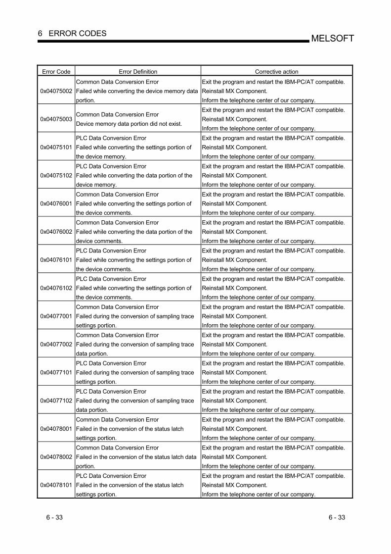
6 - 33 6 - 33
MELSOFT6 ERROR CODES
Error Code Error Definition Corrective action
0x04075002 Common Data Conversion Error Failed while converting the device memory data portion.
Exit the program and restart the IBM-PC/AT compatible. Reinstall MX Component. Inform the telephone center of our company.
0x04075003 Common Data Conversion Error Device memory data portion did not exist.
Exit the program and restart the IBM-PC/AT compatible. Reinstall MX Component. Inform the telephone center of our company.
0x04075101 PLC Data Conversion Error Failed while converting the settings portion of the device memory.
Exit the program and restart the IBM-PC/AT compatible. Reinstall MX Component. Inform the telephone center of our company.
0x04075102 PLC Data Conversion Error Failed while converting the data portion of the device memory.
Exit the program and restart the IBM-PC/AT compatible. Reinstall MX Component. Inform the telephone center of our company.
0x04076001 Common Data Conversion Error Failed while converting the settings portion of the device comments.
Exit the program and restart the IBM-PC/AT compatible. Reinstall MX Component. Inform the telephone center of our company.
0x04076002 Common Data Conversion Error Failed while converting the data portion of the device comments.
Exit the program and restart the IBM-PC/AT compatible. Reinstall MX Component. Inform the telephone center of our company.
0x04076101 PLC Data Conversion Error Failed while converting the settings portion of the device comments.
Exit the program and restart the IBM-PC/AT compatible. Reinstall MX Component. Inform the telephone center of our company.
0x04076102 PLC Data Conversion Error Failed while converting the settings portion of the device comments.
Exit the program and restart the IBM-PC/AT compatible. Reinstall MX Component. Inform the telephone center of our company.
0x04077001 Common Data Conversion Error Failed during the conversion of sampling trace settings portion.
Exit the program and restart the IBM-PC/AT compatible. Reinstall MX Component. Inform the telephone center of our company.
0x04077002 Common Data Conversion Error Failed during the conversion of sampling trace data portion.
Exit the program and restart the IBM-PC/AT compatible. Reinstall MX Component. Inform the telephone center of our company.
0x04077101 PLC Data Conversion Error Failed during the conversion of sampling trace settings portion.
Exit the program and restart the IBM-PC/AT compatible. Reinstall MX Component. Inform the telephone center of our company.
0x04077102 PLC Data Conversion Error Failed during the conversion of sampling trace data portion.
Exit the program and restart the IBM-PC/AT compatible. Reinstall MX Component. Inform the telephone center of our company.
0x04078001 Common Data Conversion Error Failed in the conversion of the status latch settings portion.
Exit the program and restart the IBM-PC/AT compatible. Reinstall MX Component. Inform the telephone center of our company.
0x04078002 Common Data Conversion Error Failed in the conversion of the status latch data portion.
Exit the program and restart the IBM-PC/AT compatible. Reinstall MX Component. Inform the telephone center of our company.
0x04078101 PLC Data Conversion Error Failed in the conversion of the status latch settings portion.
Exit the program and restart the IBM-PC/AT compatible. Reinstall MX Component. Inform the telephone center of our company.
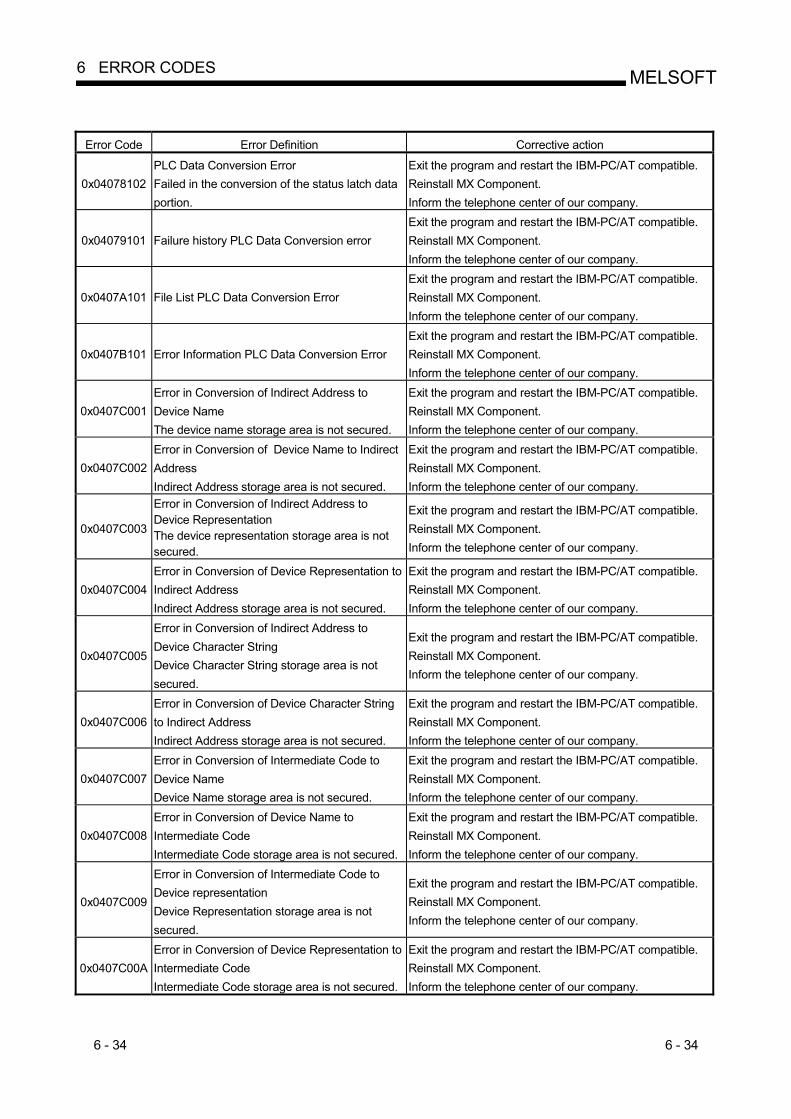
6 - 34 6 - 34
MELSOFT6 ERROR CODES
Error Code Error Definition Corrective action
0x04078102 PLC Data Conversion Error Failed in the conversion of the status latch data portion.
Exit the program and restart the IBM-PC/AT compatible. Reinstall MX Component. Inform the telephone center of our company.
0x04079101 Failure history PLC Data Conversion error Exit the program and restart the IBM-PC/AT compatible. Reinstall MX Component. Inform the telephone center of our company.
0x0407A101 File List PLC Data Conversion Error Exit the program and restart the IBM-PC/AT compatible. Reinstall MX Component. Inform the telephone center of our company.
0x0407B101 Error Information PLC Data Conversion Error Exit the program and restart the IBM-PC/AT compatible. Reinstall MX Component. Inform the telephone center of our company.
0x0407C001 Error in Conversion of Indirect Address to Device Name The device name storage area is not secured.
Exit the program and restart the IBM-PC/AT compatible. Reinstall MX Component. Inform the telephone center of our company.
0x0407C002 Error in Conversion of Device Name to Indirect Address Indirect Address storage area is not secured.
Exit the program and restart the IBM-PC/AT compatible. Reinstall MX Component. Inform the telephone center of our company.
0x0407C003
Error in Conversion of Indirect Address to Device Representation The device representation storage area is not secured.
Exit the program and restart the IBM-PC/AT compatible. Reinstall MX Component. Inform the telephone center of our company.
0x0407C004 Error in Conversion of Device Representation to Indirect Address Indirect Address storage area is not secured.
Exit the program and restart the IBM-PC/AT compatible. Reinstall MX Component. Inform the telephone center of our company.
0x0407C005
Error in Conversion of Indirect Address to Device Character String Device Character String storage area is not secured.
Exit the program and restart the IBM-PC/AT compatible. Reinstall MX Component. Inform the telephone center of our company.
0x0407C006 Error in Conversion of Device Character String to Indirect Address Indirect Address storage area is not secured.
Exit the program and restart the IBM-PC/AT compatible. Reinstall MX Component. Inform the telephone center of our company.
0x0407C007 Error in Conversion of Intermediate Code to Device Name Device Name storage area is not secured.
Exit the program and restart the IBM-PC/AT compatible. Reinstall MX Component. Inform the telephone center of our company.
0x0407C008 Error in Conversion of Device Name to Intermediate Code Intermediate Code storage area is not secured.
Exit the program and restart the IBM-PC/AT compatible. Reinstall MX Component. Inform the telephone center of our company.
0x0407C009
Error in Conversion of Intermediate Code to Device representation Device Representation storage area is not secured.
Exit the program and restart the IBM-PC/AT compatible. Reinstall MX Component. Inform the telephone center of our company.
0x0407C00A Error in Conversion of Device Representation to Intermediate Code Intermediate Code storage area is not secured.
Exit the program and restart the IBM-PC/AT compatible. Reinstall MX Component. Inform the telephone center of our company.
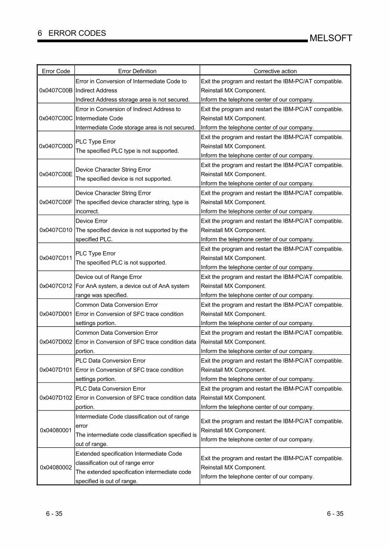
6 - 35 6 - 35
MELSOFT6 ERROR CODES
Error Code Error Definition Corrective action
0x0407C00B Error in Conversion of Intermediate Code to Indirect Address Indirect Address storage area is not secured.
Exit the program and restart the IBM-PC/AT compatible. Reinstall MX Component. Inform the telephone center of our company.
0x0407C00C Error in Conversion of Indirect Address to Intermediate Code Intermediate Code storage area is not secured.
Exit the program and restart the IBM-PC/AT compatible. Reinstall MX Component. Inform the telephone center of our company.
0x0407C00D PLC Type Error The specified PLC type is not supported.
Exit the program and restart the IBM-PC/AT compatible. Reinstall MX Component. Inform the telephone center of our company.
0x0407C00E Device Character String Error The specified device is not supported.
Exit the program and restart the IBM-PC/AT compatible. Reinstall MX Component. Inform the telephone center of our company.
0x0407C00F Device Character String Error The specified device character string, type is incorrect.
Exit the program and restart the IBM-PC/AT compatible. Reinstall MX Component. Inform the telephone center of our company.
0x0407C010 Device Error The specified device is not supported by the specified PLC.
Exit the program and restart the IBM-PC/AT compatible. Reinstall MX Component. Inform the telephone center of our company.
0x0407C011 PLC Type Error The specified PLC is not supported.
Exit the program and restart the IBM-PC/AT compatible. Reinstall MX Component. Inform the telephone center of our company.
0x0407C012 Device out of Range Error For AnA system, a device out of AnA system range was specified.
Exit the program and restart the IBM-PC/AT compatible. Reinstall MX Component. Inform the telephone center of our company.
0x0407D001 Common Data Conversion Error Error in Conversion of SFC trace condition settings portion.
Exit the program and restart the IBM-PC/AT compatible. Reinstall MX Component. Inform the telephone center of our company.
0x0407D002 Common Data Conversion Error Error in Conversion of SFC trace condition data portion.
Exit the program and restart the IBM-PC/AT compatible. Reinstall MX Component. Inform the telephone center of our company.
0x0407D101 PLC Data Conversion Error Error in Conversion of SFC trace condition settings portion.
Exit the program and restart the IBM-PC/AT compatible. Reinstall MX Component. Inform the telephone center of our company.
0x0407D102 PLC Data Conversion Error Error in Conversion of SFC trace condition data portion.
Exit the program and restart the IBM-PC/AT compatible. Reinstall MX Component. Inform the telephone center of our company.
0x04080001
Intermediate Code classification out of range error The intermediate code classification specified is out of range.
Exit the program and restart the IBM-PC/AT compatible. Reinstall MX Component. Inform the telephone center of our company.
0x04080002
Extended specification Intermediate Code classification out of range error The extended specification intermediate code specified is out of range.
Exit the program and restart the IBM-PC/AT compatible. Reinstall MX Component. Inform the telephone center of our company.

6 - 36 6 - 36
MELSOFT6 ERROR CODES
Error Code Error Definition Corrective action
0x04080003 Device Points check absent error The device does not check the device points.
Exit the program and restart the IBM-PC/AT compatible. Reinstall MX Component. Inform the telephone center of our company.
0x04090001 GPP Project Error The specified PLC type and GPP project type are not matching.
Exit the program and restart the IBM-PC/AT compatible. Reinstall MX Component. Inform the telephone center of our company.
0x04090002 File Type Error The specified GPP project type and file type are not matching.
Exit the program and restart the IBM-PC/AT compatible. Reinstall MX Component. Inform the telephone center of our company.
0x04090010 Insufficient GPP Data to be converted There is no data to be converted. The data size specified is incorrect.
Exit the program and restart the IBM-PC/AT compatible. Reinstall MX Component. Inform the telephone center of our company.
0x04090011 Insufficient Storage Space for Converted Data The space for storing converted data is insufficient.
Exit the program and restart the IBM-PC/AT compatible. Reinstall MX Component. Inform the telephone center of our company.
0x04090012 Error in GPP Data to be converted The GPP data to be converted is incorrect.
Exit the program and restart the IBM-PC/AT compatible. Reinstall MX Component. Inform the telephone center of our company.
0x04090110 Insufficient Data to be converted error There is no data to be converted. The data size specified is insufficient.
Exit the program and restart the IBM-PC/AT compatible. Reinstall MX Component. Inform the telephone center of our company.
0x04090111
Insufficient Storage Space for Converted Data error. The storage space for converted data is insufficient.
Exit the program and restart the IBM-PC/AT compatible. Reinstall MX Component. Inform the telephone center of our company.
0x04090112 Error in data to be converted The data to be converted is incorrect.
Exit the program and restart the IBM-PC/AT compatible. Reinstall MX Component. Inform the telephone center of our company.
0x04FFFFFF Other Errors Exit the program and restart the IBM-PC/AT compatible. Reinstall MX Component. Inform the telephone center of our company.
0x10000001 No Command error Exit the program and restart the IBM-PC/AT compatible. Reinstall MX Component. Inform the telephone center of our company.
0x10000002 Start of communication DLL of MX Component failed.
Exit the program and restart the IBM-PC/AT compatible. Reinstall MX Component.
0x10000003 Open failed. (DiskDrive) Exit the program and restart the IBM-PC/AT compatible. Reinstall MX Component.
0x10000004 Duplex open error Exit the program and restart the IBM-PC/AT compatible.
0x10000005 File Access Error Exit the program and restart the IBM-PC/AT compatible. Reinstall MX Component. Inform the telephone center of our company.
0x10000006 Incorrect Folder Name error Exit the program and restart the IBM-PC/AT compatible. Reinstall MX Component. Inform the telephone center of our company.

6 - 37 6 - 37
MELSOFT6 ERROR CODES
Error Code Error Definition Corrective action
0x10000007 File Access Denied error Exit the program and restart the IBM-PC/AT compatible. Reinstall MX Component. Inform the telephone center of our company.
0x10000008 Disk Full Error Exit the program and restart the IBM-PC/AT compatible. Reinstall MX Component. Inform the telephone center of our company.
0x10000009 File Delete Error Exit the program and restart the IBM-PC/AT compatible. Reinstall MX Component. Inform the telephone center of our company.
0x1000000A Incorrect File Name error Exit the program and restart the IBM-PC/AT compatible. Reinstall MX Component. Inform the telephone center of our company.
0x1000000C Execution failed since another application or thread is making a request.
Execute again after some time. Perform programming according to the multithread rules of COM and ActiveX. Exit the program and restart the IBM-PC/AT compatible.
0x1000000D Folder Creation Error Exit the program and restart the IBM-PC/AT compatible. Reinstall MX Component. Inform the telephone center of our company.
0x1000000E Folder/ File Type Error Exit the program and restart the IBM-PC/AT compatible. Reinstall MX Component. Inform the telephone center of our company.
0x1000000F Offset Address Error Exit the program and restart the IBM-PC/AT compatible. Reinstall MX Component. Inform the telephone center of our company.
0x10000010 Request Cancel Cancel Process has occurred.
Exit the program and restart the IBM-PC/AT compatible. Reinstall MX Component. Inform the telephone center of our company.
0x10000011 Memory securing error Exit the program and restart the IBM-PC/AT compatible. Reinstall MX Component.
0x10000012 Open not yet executed Exit the program and restart the IBM-PC/AT compatible.
0x10000013 Attach Not Executed error Exit the program and restart the IBM-PC/AT compatible. Reinstall MX Component. Inform the telephone center of our company.
0x10000014 Object Invalid error Exit the program and restart the IBM-PC/AT compatible. Reinstall MX Component. Inform the telephone center of our company.
0x10000015 Request Cancel Failed error Exit the program and restart the IBM-PC/AT compatible. Reinstall MX Component. Inform the telephone center of our company.
0x10000016 Failed in Reading Status error Exit the program and restart the IBM-PC/AT compatible. Reinstall MX Component. Inform the telephone center of our company.
0x10000017 The specified size (number of devices) is unauthorised.
Check the number of points specified in the method. Exit the program and restart the IBM-PC/AT compatible.
0x10000018 There is no registered device. Exit the program and restart the IBM-PC/AT compatible.

6 - 38 6 - 38
MELSOFT6 ERROR CODES
Error Code Error Definition Corrective action
0x10000019 Dataset Not Executed Exit the program and restart the IBM-PC/AT compatible. Reinstall MX Component. Inform the telephone center of our company.
0x1000001A Read Not Executed error Exit the program and restart the IBM-PC/AT compatible. Reinstall MX Component. Inform the telephone center of our company.
0x1000001B Incorrect Create Flag error Exit the program and restart the IBM-PC/AT compatible. Reinstall MX Component. Inform the telephone center of our company.
0x1000001C Operation Over Access Exit the program and restart the IBM-PC/AT compatible. Reinstall MX Component. Inform the telephone center of our company.
0x1000001D Redundant Device error Exit the program and restart the IBM-PC/AT compatible. Reinstall MX Component. Inform the telephone center of our company.
0x1000001E Registry search failed. Exit the program and restart the IBM-PC/AT compatible. Exit other programs and secure free memory area. Reinstall MX Component.
0x1000001F File Type Error Exit the program and restart the IBM-PC/AT compatible. Reinstall MX Component. Inform the telephone center of our company.
0x10000020 Device Memory Type Error Exit the program and restart the IBM-PC/AT compatible. Reinstall MX Component. Inform the telephone center of our company.
0x10000021 Program Range Error Exit the program and restart the IBM-PC/AT compatible. Reinstall MX Component. Inform the telephone center of our company.
0x10000022 TEL Type Error Exit the program and restart the IBM-PC/AT compatible. Reinstall MX Component. Inform the telephone center of our company.
0x10000023 TEL Access Error Exit the program and restart the IBM-PC/AT compatible. Reinstall MX Component. Inform the telephone center of our company.
0x10000024 Cancel Flag Type Error Exit the program and restart the IBM-PC/AT compatible. Reinstall MX Component. Inform the telephone center of our company.
0x10000030 Multiple Device Registration Error Exit the program and restart the IBM-PC/AT compatible. Reinstall MX Component. Inform the telephone center of our company.
0x10000031 Device Not Registered error Exit the program and restart the IBM-PC/AT compatible. Reinstall MX Component. Inform the telephone center of our company.
0x10000032 Specified device error Review the specified device data. Exit the program and restart the IBM-PC/AT compatible. Exit other programs and secure free memory area.

6 - 39 6 - 39
MELSOFT6 ERROR CODES
Error Code Error Definition Corrective action
0x10000033 Specified device range error Review the specified device data. Exit the program and restart the IBM-PC/AT compatible. Exit other programs and secure free memory area.
0x10000034 File Write Error Exit the program and restart the IBM-PC/AT compatible. Reinstall MX Component. Inform the telephone center of our company.
0x10000040 Server start failed. Exit the program and restart the IBM-PC/AT compatible. Reinstall MX Component. Inform the telephone center of our company.
0x10000041 Server Stop Error Failed while stopping the server
Exit the program and restart the IBM-PC/AT compatible. Reinstall MX Component. Inform the telephone center of our company.
0x10000042 Server Started Twice error Exit the program and restart the IBM-PC/AT compatible. Reinstall MX Component. Inform the telephone center of our company.
0x10000043 Server Not Started error Exit the program and restart the IBM-PC/AT compatible. Reinstall MX Component. Inform the telephone center of our company.
0x10000044 Resource Timeout Error Exit the program and restart the IBM-PC/AT compatible. Reinstall MX Component. Inform the telephone center of our company.
0x10000045 Server Type Error Exit the program and restart the IBM-PC/AT compatible. Reinstall MX Component. Inform the telephone center of our company.
0x10000046 Failed to Access Server error Exit the program and restart the IBM-PC/AT compatible. Reinstall MX Component. Inform the telephone center of our company.
0x10000047 Server Already Accessed error Exit the program and restart the IBM-PC/AT compatible. Reinstall MX Component. Inform the telephone center of our company.
0x10000048 Failed in Simulator Startup Exit the program and restart the IBM-PC/AT compatible. Reinstall MX Component. Inform the telephone center of our company.
0x10000049 Failed in exiting Simulator Exit the program and restart the IBM-PC/AT compatible. Reinstall MX Component. Inform the telephone center of our company.
0x1000004A Simulator Not Started error Exit the program and restart the IBM-PC/AT compatible. Reinstall MX Component. Inform the telephone center of our company.
0x1000004B Simulator Type Error Exit the program and restart the IBM-PC/AT compatible. Reinstall MX Component. Inform the telephone center of our company.
0x1000004C Simulator Not Supported error Exit the program and restart the IBM-PC/AT compatible. Reinstall MX Component. Inform the telephone center of our company.
0x1000004D Simulator Started Twice error Exit the program and restart the IBM-PC/AT compatible. Reinstall MX Component. Inform the telephone center of our company.

6 - 40 6 - 40
MELSOFT6 ERROR CODES
Error Code Error Definition Corrective action
0x1000004E Shared Memory Not Started error Exit the program and restart the IBM-PC/AT compatible. Reinstall MX Component. Inform the telephone center of our company.
0xF0000001 No-license error The license is not given to the IBM-PC/AT compatible.
Using the license FD, give the license to the IBM-PC/AT compatible.
0xF0000002 Set data read error Reading of the set data of the logical station number failed.
Specify the correct logical station number. Set the logical station number on the communication settings utility.
0xF0000003 Already open error The Open method was executed in the open status.
When changing the communication target CPU, execute the Open method after performing Close.
0xF0000004 Not yet open error The Open method is not yet executed.
After executing the Open method, execute the corresponding method.
0xF0000005 Initialisation error Initialisation of the object possessed internally in MX Component failed.
Exit the program and restart the IBM-PC/AT compatible. Reinstall MX Component.
0xF0000006 Memory securing error Securing of MX Component internal memory failed.
Exit the program and restart the IBM-PC/AT compatible. Exit other programs and secure free memory area.
0xF0000007 Function non-support error The method does not support.
Can not use because the corresponding method is not supported.
0xF1000001 Character code conversion error Character code conversion (UNICODE ASCII code or ASCII code UNICODE) failed.
Check the character string specified in the method. The ASCII character string acquired from the PLC CPU is abnormal. Review the system, e.g. PLC CPU, module setting and cable status. Exit the program and restart the IBM-PC/AT compatible. Retry the GetCpuType method.
0xF1000002
First I/O number error The first I/O number specified is an unauthorised value. A matching first I/O number does not exist.
Check the value of the first I/O number specified in the method. Using the GPP function, check the PLC CPU parameters (I/O assignment).
0xF1000003
Buffer address error The buffer address specified is an unauthorised value. The buffer address is outside the range.
Check the value of the buffer address specified in the method.
0xF1000004 Buffer read size error As a result of buffer read, the specified size could not be acquired.
Perform reopen processing. Review the system, e.g. PLC CPU, module setting and cable status. Retry. Exit the program.
0xF1000005
Size error The size specified in the read/write method is abnormal. The read/write first number plus size exceeds the device or buffer area.
Check the size specified in the method.

6 - 41 6 - 41
MELSOFT6 ERROR CODES
Error Code Error Definition Corrective action
0xF1000006 Operation error The operation specified for remote operation is an abnormal value.
Check the operation specifying value specified in the method.
0xF1000007 Clock data error The clock data is abnormal.
Check the clock data specified in the method. Set the correct clock data to the clock data of the PLC CPU.
0xF1000008
Monitored device registration count excess The number of device points registered in the EntryDeviceStatus method was 0 or less. The number of device points registered in the EntryDeviceStatus method was more than 20.
Register the device points between 1 and 20 in the EntryDeviceStaus method.
0xF1000009 Monitored device data registration error After making deregistration in the FreeDeviceStatus method, execute the EntryDeviceStatus method again.
0xF1000010 Device status monitor processing failed to start. Device status monitor processing failed to end.
Start/end the device status monitor processing again in the EntryDeviceStatus method.
0xF1000011 The VARIANT argument data type is wrong.
Reexamine the data type specified for the VARIANT argument. • Check whether the array variable size is large enough. • Check whether the data type specified in the corresponding method has been set.
0xF1000012 The device status monitoring time interval is a value outside the range 1 second to 1 hour (1 to 3600).
Specify the device status monitoring time between 1 and 3600.
0xF1000013 Already Connected error. Connect was executed again after it was executed for the same object.
Execute the Connect method after executing the Disconnect method.
0xF1000014 Invalid Telephone Number error. Characters other than “0123456789-*#” that are allowed for telephone numbers are included.
Rectify the Telephone number and try to Connect again.
0xF1000015
Exclusive Control Failure error. There was failure in the exclusive control process while executing the Connect and Disconnect method.
In case if Connect/Disconnect method is being executed for any other object, execute the failed method (Connect/Disconnect) again after the completion of the Connect/ Disconnect method of that object. If the Connect/Disconnect process is in progress only for the self object, perform the following. Exit the program. Restart the IBM-PC/AT compatible. Reinstall MX Component.
0xF1000016
While connecting to the telephone line error. The telephone line is connected to some other application, other than the one using MXComponent.
Try Connecting again after disconnecting the application that is using the telephone line.

6 - 42 6 - 42
MELSOFT6 ERROR CODES
Error Code Error Definition Corrective action
0xF1000017
Telephone line not connected error. Telephone line is not connected. Connect was executed and the telephone line was connected, but it got disconnected due to some reason.
(When Connect method has failed) Execute Connect again after executing Disconnect method. (When method other than Connect has failed) Execute Disconnect method, Execute Connect and connect to the telephone line. After connecting, execute the method that failed once again.
0xF1000018
No Telephone number error. The telephone No. is not set. The telephone No. or call back No. is not set,if the connection method is Automatic (when specifying the call back No.), call back connection (when specifying the number), or call back Request(when specifying the number).
In case of program settings type,set the telephone No. to the property ActDialNumber. (Set the telephone No. to the properties ActDialNumber and ActCallbackNumber, if the connection method is automatic (when specifying the call back No.), call back connection (when specifying the telephone No.), or call back request (when specifying the number).) In case of utility settings type,set the telephone No. using the wizard. (Set the telephone No. and call back No. , if the connection method is automatic (when specifying the call back No.), call back connection (when specifying the telephone No.), or call back request (when specifying the number).)
0xF1000019 Not Closed error. Disconnect was executed while in Open state.
Try Disconnect again after executing Close.
0xF100001A
Target telephone line connection mismatch error. Connect was tried for a different telephone number using the port which is already connected to a telephone line. (When the method of connection is a callback reception, it is considered that the telephone number is different from methods of connection in other than the callback reception.)
If you want to connect to a different telephone number, Execute Disconnect with respect to the telephone line that is already connected and executes Connect after it gets disconnected. In case of connecting the telephone line with callback reception, use the Connect of the connection method that is executed at the earliest in the same port as callback reception.
0xF100001B
Control Type Mismatch error. An object, whose control type is different from that of the object already connected to the telephone line, tried to Connect.
Execute Disconnect for the object currently connected to the telephone line and execute Connect once again after the telephone line gets disconnected.
0xF100001C
Not Disconnected error. When Disconnect method is executed for the object connected to the telephone line, it is found that other objects are in connected state.
Execute Disconnect for all the Connected objects. Try Disconnect again for the object that actually performed the telephone line connection.
0xF100001D Not Connected error. Open was executed before Connect Or, Disconnect was executed.
Execute Open again after executing Connect. Or execute Disconnect again after executing Connect.

6 - 43 6 - 43
MELSOFT6 ERROR CODES
Error Code Error Definition Corrective action
0xF100001E Fatal Error.
Exit the program. Restart the IBM-PC/AT compatible. Reinstall MX Component. Inform the telephone center of our company.
0xF100001F
Open time setting error There is some difference in telephone number and the port number settings used during Connect and Open.There is some error in Connect way.
Check the telephone numebr and the portnumebr. Check the Connect way.
0xF2000002
There is an error response from the target telephone. Causes can be the following. * Communication error has occurred.
Check the value of the properties set in case of program settings type and check the contents of the detailed settings that were set using the wizard in case of utility settings type.
0xF2000003
Invalid data was received. Causes can be the following. * Incorrect data packet received due to noise. * Communicated with a device other than
A(Q)6TEL/C24.
Retry. Check the communication device used at the other end.
0xF2000004
There is no response from the modem. Causes can be the following. Abnormality in the modem. Telephone number setting mistake.
Check the status of the modem. Check the telephone number. If the problem persists even after checking the above points, change the value of the properties set (Properties such as ActConnectionCDWaitTime etc. , which set the timings) in case of program settings type and change the contents of the detailed settings that were set using the wizard in case of utility settings type.
0xF2000005 There are chances that the line is not disconnected.
Check the line.
0xF2000006
The PC modem did not receive the AT command. Causes can be the following. * Invalid AT command was specified. * Abnormality in the modem.
Check the contents of the AT command. Check the status of the modem.
0xF2000007 Modem did not respond properly to the standard escape command.
Check the modem. Confirm whether the value of the time-out is too small. ( 5000ms or more is recommended. )
0xF2000009 Modem does not respond properly to the line Disconnect command.
Check the modem.
0xF200000A
Target did not receive the signal. * The Receive settings of the modem at the
other end may be incorrect. * The other end may be busy. * The telephone number may be incorrect.
Check the Receive settings of the modem at the other end. Check if the other end is busy. Check the telephone number.
0xF200000B Timeout reached for the call back receive waiting time.
Increase the call back receive waiting time ActCallbackReveptionWaitingTimeOut and execute connect again.

6 - 44 6 - 44
MELSOFT6 ERROR CODES
Error Code Error Definition Corrective action
0xF200000C Password of A6TEL, Q6TEL, QJ71C24 units could not be resolved.
Set the password to ActPassword property and execute the failed method again.
0xF2010001
The callback line disconnect wait time is other than 0 -180 Seconds. The callback execution delay time is other than 0 -1800 Seconds. The telephone number is more than 62 characters.
Check whether the callback line disconnect wait time is with in 0 – 180 Seconds. Check whether the callback execution delay time is with in 0 - 1800 Seconds. Check whether the telephone number is less than or equal to 62 characters. Exit the program and restart the IBM-PC/AT compatible. Reinstall MX Component. Inform the telephone center of our company.
0xF2010002
QJ71C24 did not receive the specified connection method. Causes can be the following. * Incorrect Connection method. * Incorrect telephone number for Call back.
Check whether the settings of QJ71C24 and the MXComponent are matching.
0xF2010003 QJ71C24 does not permit the automatic connection (during fixed Call back or when the number is specified.)
Check the settings of QJ71C24.
0xF2100005 There are chances that the line is not disconnected.
If there is no problem with the modem or the telephone line, change the value of the properties set (Properties like ActConnectionCDWaitTime etc. , which set the timings) in case of program settings type and change the contents of the detailed settings that were set using the wizard in case of utility settings type.
0xF2100008 There was no response from the modem for the data sent from the PC.
Change the value of the properties set (Properties such as ActConnectionCDWaitTime etc. , which set the timings) in case of program settings type and change the contents of the detailed settings that were set using the wizard in case of utility settings type.
0xF2100006 Modem did not receive the startup command AT.
Change the settings of the property ActATCommand. in case of program settings type and change the command AT that were set using the wizard in case of utility settings type.
0xF2100007 The PC modem does not respond to the Escape command.
If there is no problem with the modem or the telephone line, change the value of the properties set (Properties like ActConnectionCDWaitTime etc. , which set the timings) in case of program settings type and change the contents of the detailed settings that were set using the wizard in case of utility settings type.

6 - 45 6 - 45
MELSOFT6 ERROR CODES
Error Code Error Definition Corrective action
0xF21000
There is no response from the modem. Causes can be the following. Abnormality in the modem. Telephone number setting mistake.
Check the status of the modem. Check the telephone number. If the problem persists even after checking the above points, change the value of the properties set (Properties such as ActConnectionCDWaitTime etc. , which set the timings) in case of program settings type and change the contents of the detailed settings that were set using the wizard in case of utility settings type.
0xF21001
There is no response from A(Q)6TEL/C24. Causes can be the following. Setting mistake w.r.t. A(Q)6TEL/C24 A(Q)6TEL/C24 got connected to a non-existant modem.
Re-examine the settings of A(Q)6TEL/C24. Confirm whether the modem exists. If the problem persists even after checking the above points, change the value of the properties set (Properties such as ActConnectionCDWaitTime etc. , which set the timings) in case of program settings type and change the contents of the detailed settings that were set using the wizard in case of utility settings type.
0xF202
There was a communication failure. Following causes can be considered depending on the status. Communication time over (Break in cable, the specified port not supported, mistake in specifying the COM port) Modem’s power is switched OFF.
Check whether the cable is broken. Check whether the specified port is not supported. Check whether correct COM port is set. Check if the modem power is switched OFF. For detailed troubleshooting, please refer to the details of the error code got after replacing the first four digits with “0x0180”. eg In case of “0xF202480B”, please refer to the code “0x0180480B”.
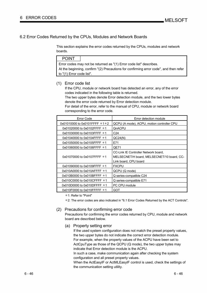
6 - 46 6 - 46
MELSOFT6 ERROR CODES
6.2 Error Codes Returned by the CPUs, Modules and Network Boards
This section explains the error codes returned by the CPUs, modules and network boards.
POINT
Error codes may not be returned as "(1) Error code list" describes. At the beginning, confirm "(2) Precautions for confirming error code", and then refer to "(1) Error code list".
(1) Error code list
If the CPU, module or network board has detected an error, any of the error codes indicated in the following table is returned. The two upper bytes denote Error detection module, and the two lower bytes denote the error code returned by Error detection module. For detail of the error, refer to the manual of CPU, module or network board corresponding to the error code.
Error Code Error detection module
0x01010000 to 0x0101FFFF 1 2 QCPU (A mode), ACPU, motion controller CPU 0x01020000 to 0x0102FFFF 1 QnACPU 0x01030000 to 0x0103FFFF 1 C24 0x01040000 to 0x0104FFFF 1 QC24(N) 0x01050000 to 0x0105FFFF 1 E71 0x01060000 to 0x0106FFFF 1 QE71
0x01070000 to 0x0107FFFF 1 CC-Link IE Controller Network board, MELSECNET/H board, MELSECNET/10 board, CC-Link board, CPU board
0x01090000 to 0x0109FFFF 1 FXCPU 0x010A0000 to 0x010AFFFF 1 QCPU (Q mode) 0x010B0000 to 0x010BFFFF 1 Q series-compatible C24 0x010C0000 to 0x010CFFFF 1 Q series-compatible E71 0x010D0000 to 0x010DFFFF 1 PC CPU module 0x010F0000 to 0x010FFFFF 1 GOT
1: Refer to "Point" 2: The error codes are also indicated in "6.1 Error Codes Returned by the ACT Controls".
(2) Precautions for confirming error code
Precautions for confirming the error codes returned by CPU, module and network board are described below.
(a) Property setting error
If the used system configuration does not match the preset property values, the two upper bytes do not indicate the correct error detection module. For example, when the property values of the ACPU have been set to ActCpuType as those of the QCPU (Q mode), the two upper bytes may indicate that Error detection module is the ACPU. In such a case, make communication again after checking the system configuration and all preset property values. When the ActEasyIF or ActMLEasyIF control is used, check the settings of the communication setting utility.
6 - 47 6 - 47
MELSOFT6 ERROR CODES
(b) When AJ71E71 or AJ71QE71 is used
If the two lower-byte error code that occurred during E71 or QE71 communication is not given in the E71 or QE71 manual, check whether the DIP switch (SW2) at the front of the E71 or QE71 module matches the value set to the ActPacketType property. If the DIP switch setting is incorrect, the packet format (ASCII/binary) is different, disabling correct recognition of the error code returned from the module.
(c) At access to another station
At access to another station, the error code of the relayed module used (CC-Link IE Controller Network, MELSECNET/H, MELSECNET/10, CC-Link, computer link, Ethernet module) may enter the two lower bytes. In such a case, the two upper bytes that indicate Error detection module may not always match the faulty module. Therefore, after checking the system configuration, also check the manuals of the used CPU, relayed network module and network board.
6.3 HRESULT Type Error Codes
Normally, the ActiveX control returns the HRESULT type returned value. So does the ACT control. When the custom interface is used, the returned value is equivalent to the returned value of method API. When the dispatch interface is used, the HRESULT type returned value can be acquired by performing exception processing. The following table indicates the HRESULT type returned values of the ACT controls.
Returned Value Termination Status Description
S_OK Normal termination Function processing terminated normally.
S_FALSE Normal termination Function processing (as ActiveX control) terminated normally, but operation (access to PLC) failed.
E_POINTER Abnormal termination The pointer passed to the function is abnormal.
E_OUTOFMEMORY Abnormal termination Memory securing or object creation failed.
E_FAIL Abnormal termination An indefinite error occurred.
POINT
If exception processing for acquiring the HRESULT type returned value has not been performed, the dispatch interface shows the error dialog box on the OS level when E_POINTER (E_XXXXX defined returned value) or the like is returned from the ACT control.

APP - 1 APP - 1
MELSOFTAPPENDICES
APPENDICES
Appendix 1 Connection System of the Callback Function
This section describes the connection system of the callback function for modem communication using the Q Series Corresponding C24. The callback function enables access from MX Component to the PLC CPU by line reconnection (callback) made from the Q Series Corresponding C24 after line connection from MX Component. For (1) to (3), telephone charges are born on the personal computer side. For (4) to (8), telephone charges are born on the Q Series Corresponding C24 side. Refer to the following manual for details of the callback function. • Q Corresponding Serial Communication Module User's Manual (Application) (1) Auto line connect
Select this when the callback function has not been set to the Q Series Corresponding C24.
(2) Auto line connect (Callback fixation) Connects the line without using the callback function when the callback function has been set to the Q Series Corresponding C24. It is allowed to connect to the only PC with telephone number registered in the buffer memory (2101H) of Q Series Corresponding C24.
(3) Auto line connect (Callback number specification) Connects the line without using the callback function when the callback function has been set to the Q Series Corresponding C24. It is allowed to connect to only the PC with telephone number specified by MX Component.
(4) Callback connect (Fixation) Callbacks only the personal computer with telephone number registered in the buffer memory (2101H) of the Q Series Corresponding C24.
(5) Callback connect (Number specification) Callbacks only the personal computer with telephone number specified by MX Component.
(6) Callback request (Fixation) Issues a callback request from any PC to callback the PCs with telephone numbers registered in the buffer memory (2101H) of Q Series Corresponding C24. (The PC that has issued the callback request will not be callbacked.)
APP

APP - 2 APP - 2
MELSOFTAPPENDICES
(7) Callback request (Number specification)
Issues a callback request from any PC to callback the PCs with telephone numbers specified by MX Component. (The PC that has issued the callback request will not be callbacked.)
(8) Callback reception waiting It is possible to connect the callback-target PC to the line during callback request (number fixation, number specification) by setting the PC to "Callback reception waiting".
APP

APP - 3 APP - 3
MELSOFTAPPENDICES
Appendix 2 Programming Example for Checking the Word Device Status
This section explains the programming example for EntryDeviceStatus to check word devices for negative values. (1) When using Visual Basic R 6.0
The following programming example checks D0 for -10, D1 for 0 and D2 for 10 using Visual Basic R 6.0.
Dim szDevice As String ´Checked device list Dim lInputData(2) As Long ´Set value Dim lEntryData(2) As Long ´Value set to argument of EntryDeviceStatus Dim lReturnCode(2) As Long ´Returned value to EntryDeviceStatus Dim lCount As Long ´Loop counter ´Sets D0, D1 and D2 to the checked device list. szDevice = "D0" + vbLf + "D1" + vbLf + "D2" ´Sets the checked device value "-10" for D0. lInputData(0) = -10 ´Sets the checked device value "0" for D1. lInputData(1) = 0 ´Sets the checked device value "10" for D2. lInputData(2) = 10 ´If the set value is negative, stores "0"s into the upper 2 bytes ´for conversion into the value to be set to EntryDeviceStatus. ´Loops through the number of device points. For lCount = 0 To 2 ´If the set value is negative If lInputData(lCount) < 0 Then
´Masks with 65535 (0000FFFF[hex]) to store ´"0"s into upper 2 bytes.
lEntryData(lCount) = lInputData(lCount) And 65535 Else ´If the set value is positive, assigns the value as-is to lEntryData. lEntryData(lCount) = lInputData(lCount)
End If Next ´Executes EntryDeviceStatus. lReturnCode = ActLLT1.EntryDeviceStatus(szDevice, 3, 5, lEntryData(0))
(To next page)

APP - 4 APP - 4
MELSOFTAPPENDICES
<When ldata = -1> Private Sub ActLLT1_OnDeviceStatus(ByVal szDevice As String, ByVal lData As Long, ByVal lReturnCode As Long)
Dim lCheckData As Long ´Value set to EntryDeviceStatus ´ (value before 0s are stored into the upper 2 bytes)
´If the device value whose condition was established is a WORD type negative value ´ (greater than 32767 (7FFF[Hex]) If lData > 32767 Then ´Since "0"s are stored in the upper 2 bytes, the device value is ORed
´with FFFF0000[Hex] to convert it into a LONG type negative value. lCheckData = lData Or &HFFFF0000
Else ´If the device value whose condition was established is positive,
´assigns the value as-is to lCheckData. lCheckData = lData End If
End Sub

APP - 5 APP - 5
MELSOFTAPPENDICES
(2) When using Visual C++ R 6.0
The following programming example checks D0 for -10, D1 for 0 and D2 for 10 using Visual C++ R 6.0.
CString szDevice; //Checked device list LONG lInputData[3]; //Set value LONG lEntryData[3]; //Value set to argument of EntryDeviceStatus LONG lReturnCode; //Returned value to EntryDeviceStatus LONG lCount; //Loop counter //Sets D0, D1 and D2 to the checked device list. szDevice = "D0\nD1\nD2"; //Sets the checked device value "-10" for D0. lInputData[0] = -10; //Sets the checked device value "0" for D1. lInputData[1] = 0; //Sets the checked device value "10" for D2. lInputData[2] = 10; //If the set value is negative, stores "0"s into the upper 2 bytes //for conversion into the value to be set to EntryDeviceStatus. //Loops through the number of device points. for(lCount = 0;lCount<=2; lCount++) { //If the set value is negative if (lInputData[lCount] < 0 ){
//Masks with 65535 (0000FFFF[hex]) to store //"0"s into upper 2 bytes.
lEntryData[lCount] = lInputData[lCount] & 0x0000FFFF; }else{ //If the set value is positive, assigns the value as-is to lEntryData. lEntryData[lCount] = lInputData[lCount];
} } //Executes EntryDeviceStatus. lReturnCode = m_ActLLT.EntryDeviceStatus(szDevice,3,5,lEntryData);
(To next page)
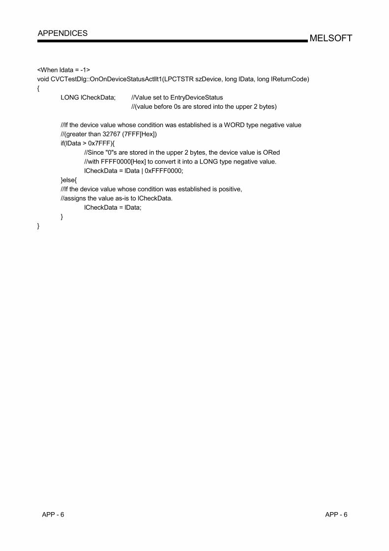
APP - 6 APP - 6
MELSOFTAPPENDICES
<When ldata = -1> void CVCTestDlg::OnOnDeviceStatusActllt1(LPCTSTR szDevice, long lData, long lReturnCode) {
LONG lCheckData; //Value set to EntryDeviceStatus //(value before 0s are stored into the upper 2 bytes)
//If the device value whose condition was established is a WORD type negative value //(greater than 32767 (7FFF[Hex]) if(lData > 0x7FFF){ //Since "0"s are stored in the upper 2 bytes, the device value is ORed
//with FFFF0000[Hex] to convert it into a LONG type negative value. lCheckData = lData | 0xFFFF0000;
}else{ //If the device value whose condition was established is positive,
//assigns the value as-is to lCheckData. lCheckData = lData; }
}

APP - 7 APP - 7
MELSOFTAPPENDICES
Appendix 3 Time-Out Periods
On MX Component, a time-out may occur for the period different from the value set to the ActTimeOut property within the ACT Control. This section explains the time-out periods in various status.
Appendix 3.1 When retries are to be made at occurrence of time-out error
If a time-out error occurs during communication, time-out processing may be repeated a maximum of three times within the ACT control. At that time, it will take a maximum of three times longer period than the set time-out value until a time-out occurs. The following shows a communication path to be retried at a time-out of error occurrence. (1) Computer link module communication
(a) Configuration
IBM-PC/AT compatible
Connected station CPU
Connected module
Relayedmodule
Relayed network
Relayed station CPU
Relayedmodule
1 2
34
(b) Target/non-target communication path
The following table indicates the communication paths to be retried at a time-out error occurrence. All the connected station CPUs can be the targets. Target/non-target relayed CPUs are indicated by (target) or (non-target).
Connected station 4. Relayed station CPU
1. CPU 2. Connected
module (Usable control name)
3. Relayed network QCPU (Q mode)
QSCPUQCPU
(A mode) QnACPU ACPU FXCPU
Motion controller
CPU CC-Link IE Controller Network
MELSECNET/H MELSECNET/10 MELSECNET(II) Ethernet Computer link CC-Link Multidrop (Independent mode)
QCPU (Q mode)
Q series-compatible C24 (ActQJ71C24,
ActMLQJ71C24)
Multidrop (Synchronous mode)
(To next page)

APP - 8 APP - 8
MELSOFTAPPENDICES
Connected station 4. Relayed station CPU
1. CPU 2. Connected
module (Usable control name)
3. Relayed network QCPU (Q mode)
QSCPUQCPU
(A mode)QnACPU ACPU FXCPU
Motion controller
CPU CC-Link IE Controller Network
MELSECNET/H MELSECNET/10 MELSECNET(II) Ethernet Computer link CC-Link Multidrop (Independent mode)
QnACPU QC24(N)
(ActAJ71QC24, ActMLAJ71QC24)
Multidrop (Synchronous mode)
CC-Link IE Controller Network
MELSECNET/H MELSECNET/10 MELSECNET(II) Ethernet Computer link CC-Link
QCPU (A mode), QnACPU,
ACPU, Motion
controller CPU
UC24 (ActAJ71UC24,
ActMLAJ71UC24)
Multidrop CC-Link IE Controller Network
MELSECNET/H MELSECNET/10 MELSECNET(II) Ethernet Computer link CC-Link
QCPU (A mode), QnACPU,
ACPU, Motion
controller CPU
C24 (ActAJ71C24,
ActMLAJ71C24)
Multidrop CC-Link IE Controller Network
MELSECNET/H MELSECNET/10 MELSECNET(II) Ethernet Computer link CC-Link
FXCPU FX extended port
(ActFX485BD, ActMLFX485BD)
Multidrop

APP - 9 APP - 9
MELSOFTAPPENDICES
(2) CPU COM communication
(a) Configuration
IBM-PC/AT compatible
Connected station CPU
Relayedmodule
Relayed network
Relayed station CPU
Relayedmodule
1
23
(b) Target/non-target communication path
The following table indicates the communication paths to be retried at a time-out error occurrence. All the connected station CPUs can be the targets. Target/non-target relayed CPUs are indicated by (target) or (non-target).
3. Relayed station CPU
1. Connected module (Usable control name)
2. Relayed network QCPU (Q mode)
QSCPUQCPU
(A mode)QnACPU ACPU FXCPU
Motion controller
CPU CC-Link IE Controller Network
MELSECNET/H MELSECNET/10 MELSECNET(II) Ethernet Computer link
QCPU (Q mode) (ActQCPUQ, ActMLQCPUQ)
CC-Link CC-Link IE Controller Network
MELSECNET/H MELSECNET/10 MELSECNET(II) Ethernet Computer link
QCPU (A mode) (ActQCPUA, ActMLQCPUA)
CC-Link CC-Link IE Controller Network
MELSECNET/H MELSECNET/10 MELSECNET(II) Ethernet Computer link
QnACPU (ActQnACPU,
ActMLQnACPU)
CC-Link
(To next page)

APP - 10 APP - 10
MELSOFTAPPENDICES
3. Relayed station CPU
1. Connected module (Usable control name)
2. Relayed network QCPU (Q mode)
QSCPUQCPU
(A mode)QnACPU ACPU FXCPU
Motion controller
CPU CC-Link IE Controller Network
MELSECNET/H MELSECNET/10 MELSECNET(II) Ethernet Computer link
ACPU, Motion controller CPU (ActACPU, ActMLACPU)
CC-Link CC-Link IE Controller Network
MELSECNET/H MELSECNET/10 MELSECNET(II) Ethernet Computer link
FXCPU (ActFXCPU, ActMLFXCPU)
CC-Link

APP - 11 APP - 11
MELSOFTAPPENDICES
(3) CPU USB communication
(a) Configuration
IBM-PC/AT compatible
Connected station CPU
Relayedmodule
Relayed network
Relayed station CPU
Relayedmodule
1
23
(b) Target/non-target communication path
The following table indicates the communication paths to be retried at a time-out error occurrence. All the connected station CPUs all become targets. Target/non-target relayed CPUs are indicated by (target) or (non-target).
3. Relayed station CPU
1. Connected module (Usable control name)
2. Relayed network QCPU (Q mode)
QSCPUQCPU
(A mode)QnACPU ACPU FXCPU
Motion controller
CPU CC-Link IE Controller Network
MELSECNET/H MELSECNET/10 MELSECNET(II) Ethernet Computer link
QCPU (Q mode) (ActQCPUQUSB,
ActMLQCPUQUSB)
CC-Link CC-Link IE Controller Network
MELSECNET/H MELSECNET/10 MELSECNET(II) Ethernet Computer link
FXCPU (ActFXCPUUSB,
ActMLFXCPUUSB)
CC-Link

APP - 12 APP - 12
MELSOFTAPPENDICES
(4) CC-Link G4 communication
(a) Configuration
2
Connected station CPU
CC-Linkmodule
Relayedmodule
Relayed network
Relayed station CPU
Relayedmodule
1
3
IBM-PC/AT compatible
CC-LinkG4module
(b) Target/non-target communication path
The following table indicates the communication paths to be retried at a time-out error occurrence. All the connected station CPUs can be the targets. Target/non-target relayed CPUs are indicated by (target) or (non-target).
1) When CC-Link G4-S3 module is in Q mode
3. Relayed station CPU 1. Connected module (Usable control name)
2. Relayed network QCPU (Q mode)
QSCPUQCPU
(A mode)QnACPU ACPU FXCPU
Motion controller
CPU CC-Link IE Controller Network
MELSECNET/H MELSECNET/10 MELSECNET(II) Ethernet Computer link
QCPU (Q mode) (ActCCG4Q, ActMLCCG4Q)
CC-Link
2) When CC-Link G4 module is in QnA mode
3. Relayed station CPU 1. Connected module (Usable control name)
2. Relayed network QCPU (Q mode)
QSCPUQCPU
(A mode)QnACPU ACPU FXCPU
Motion controller
CPU CC-Link IE Controller Network
MELSECNET/H MELSECNET/10 MELSECNET(II) Ethernet Computer link
QnACPU (ActCCG4QnA,
ActMLCCG4QnA)
CC-Link

APP - 13 APP - 13
MELSOFTAPPENDICES
3) When CC-Link G4 module is in A mode
3. Relayed station CPU 1. Connected module (Usable control name)
2. Relayed network QCPU (Q mode) QSCPU
QCPU (A mode)
QnACPU ACPU FXCPUMotion
controller CPU
CC-Link IE Controller Network
MELSECNET/H MELSECNET/10 MELSECNET(II) Ethernet Computer link
QCPU (A mode), ACPU, Motion controller CPU
(ActCCG4A, ActMLCCG4A)
CC-Link
(5) Modem communication
(a) When A6TEL is used 1) Configuration
Connected station CPU
Relayedmodule
Relayed network
Relayed station CPU
Relayedmodule
IBM-PC/AT compatible
Modem
Subscriber line
Modem
1
23
2) Target/non-target communication path
The following table indicates the communication paths to be retried at a time-out error occurrence. All the connected station CPUs can be the targets. Target/non-target relayed CPUs are indicated by (target) or (non-target).
Connected station 3. Relayed station CPU
1. CPU Connected
module (Usable control name)
2. Relayed network QCPU (Q mode) QSCPU
QCPU (A mode)
QnACPU ACPU FXCPUMotion
controller CPU
CC-Link IE Controller Network
MELSECNET/H MELSECNET/10 MELSECNET(II) Ethernet Computer link
ACPU, Motion
controller CPU
A6TEL, Q6TEL (A mode)
(ActA6TEL)
CC-Link

APP - 14 APP - 14
MELSOFTAPPENDICES
(b) When Q6TEL is used
1) Configuration
Connected station CPU
Relayedmodule
Relayed network
Relayed station CPU
Relayedmodule
IBM-PC/AT compatible
Modem
Subscriber line
Modem
1
23
2) Target/non-target communication path
The following table indicates the communication paths to be retried at a time-out error occurrence. All the connected station CPUs can be the targets. Target/non-target the relayed CPUs are indicated by (target) or (non-target).
Connected station 3. Relayed station CPU
1. CPU Connected
module (Usable control name)
2. Relayed network QCPU (Q mode) QSCPU
QCPU (A mode)
QnACPU ACPU FXCPUMotion
controller CPU
CC-Link IE Controller Network
MELSECNET/H MELSECNET/10 MELSECNET(II) Ethernet Computer link
QnACPU Q6TEL,
(QnA mode) (ActQ6TEL)
CC-Link

APP - 15 APP - 15
MELSOFTAPPENDICES
(c) When FXCPU is used
1) Configuration
Connected station CPU
Relayedmodule
Relayed network
Relayed station CPU
Relayedmodule
IBM-PC/AT compatible
Modem
Subscriber line
Modem
1
23
2) Target/non-target communication path
The following table indicates the communication paths to be retried at a time-out error occurrence. All the connected station CPUs can be the targets. Target/non-target relayed CPUs are indicated by (target) or (non-target).
3. Relayed station CPU
1. Connected module (Usable control name)
2. Relayed network QCPU (Q mode) QSCPU
QCPU (A mode)
QnACPU ACPU FXCPUMotion
controller CPU
CC-Link IE Controller Network
MELSECNET/H MELSECNET/10 MELSECNET(II) Ethernet Computer link
FXCPU (ActFXCPUTEL)
CC-Link
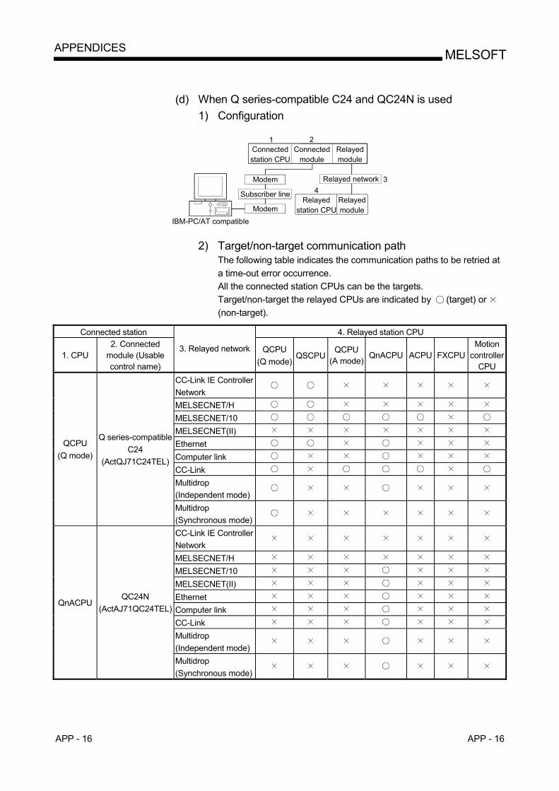
APP - 16 APP - 16
MELSOFTAPPENDICES
(d) When Q series-compatible C24 and QC24N is used
1) Configuration
Connected station CPU
Relayedmodule
Relayed network
Relayed station CPU
Relayedmodule
IBM-PC/AT compatible
Modem
Subscriber line
Modem
1
34
Connected module
2
2) Target/non-target communication path
The following table indicates the communication paths to be retried at a time-out error occurrence. All the connected station CPUs can be the targets. Target/non-target the relayed CPUs are indicated by (target) or (non-target).
Connected station 4. Relayed station CPU
1. CPU 2. Connected
module (Usable control name)
3. Relayed network QCPU (Q mode)
QSCPUQCPU
(A mode)QnACPU ACPU FXCPU
Motion controller
CPU CC-Link IE Controller Network
MELSECNET/H MELSECNET/10 MELSECNET(II) Ethernet Computer link CC-Link Multidrop (Independent mode)
QCPU (Q mode)
Q series-compatible C24
(ActQJ71C24TEL)
Multidrop (Synchronous mode)
CC-Link IE Controller Network
MELSECNET/H MELSECNET/10 MELSECNET(II) Ethernet Computer link CC-Link Multidrop (Independent mode)
QnACPU QC24N
(ActAJ71QC24TEL)
Multidrop (Synchronous mode)
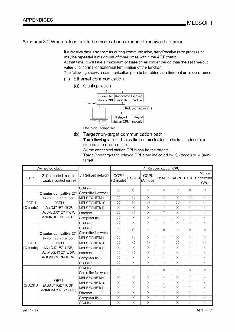
APP - 17 APP - 17
MELSOFTAPPENDICES
Appendix 3.2 When retries are to be made at occurrence of receive data error
If a receive data error occurs during communication, send/receive retry processing may be repeated a maximum of three times within the ACT control. At that time, it will take a maximum of three times longer period than the set time-out value until normal or abnormal termination of the function. The following shows a communication path to be retried at a time-out error occurrence. (1) Ethernet communication
(a) Configuration
IBM-PC/AT compatible
Connected station CPU
Connected module
Relayedmodule
Relayed network
Relayed station CPU
Relayedmodule
1 2
34
Ethernet
(b) Target/non-target communication path
The following table indicates the communication paths to be retried at a time-out error occurrence. All the connected station CPUs can be the targets. Target/non-target the relayed CPUs are indicated by (target) or (non-target).
Connected station 4. Relayed station CPU
1. CPU 2. Connected module (Usable control name)
3. Relayed network QCPU (Q mode)
QSCPUQCPU
(A mode)QnACPU ACPU FXCPU
Motion controller
CPU CC-Link IE Controller Network
MELSECNET/H MELSECNET/10 MELSECNET(II) Ethernet Computer link
QCPU (Q mode)
Q series-compatible E71 Built-in Ethernet port
QCPU (ActQJ71E71TCP,
ActMLQJ71E71TCP, ActQNUDECPUTCP)
CC-Link CC-Link IE Controller Network
MELSECNET/H MELSECNET/10 MELSECNET(II) Ethernet Computer link
QCPU (Q mode)
Q series-compatible E71 Built-in Ethernet port
QCPU (ActQJ71E71UDP,
ActMLQJ71E71UDP, ActQNUDECPUUDP)
CC-Link CC-Link IE Controller Network
MELSECNET/H MELSECNET/10 MELSECNET(II) Ethernet Computer link
QnACPU QE71
(ActAJ71QE71UDP, ActMLAJ71QE71UDP)
CC-Link
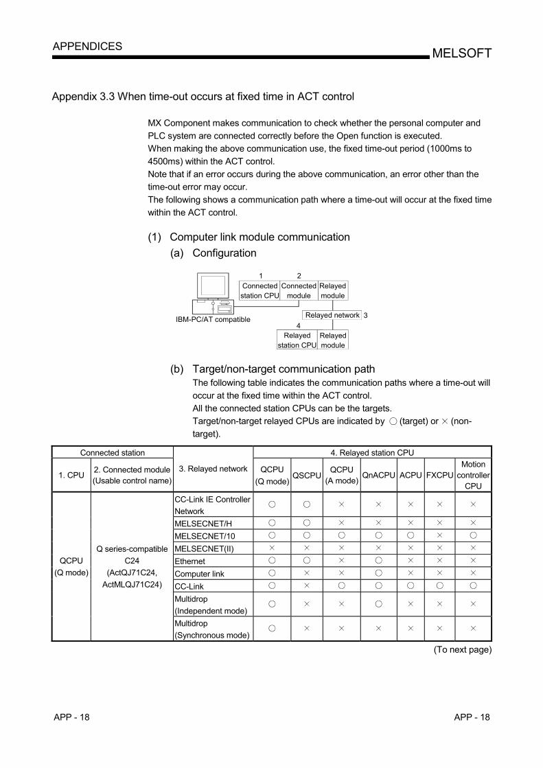
APP - 18 APP - 18
MELSOFTAPPENDICES
Appendix 3.3 When time-out occurs at fixed time in ACT control
MX Component makes communication to check whether the personal computer and PLC system are connected correctly before the Open function is executed. When making the above communication use, the fixed time-out period (1000ms to 4500ms) within the ACT control. Note that if an error occurs during the above communication, an error other than the time-out error may occur. The following shows a communication path where a time-out will occur at the fixed time within the ACT control. (1) Computer link module communication
(a) Configuration
IBM-PC/AT compatible
Connected station CPU
Connected module
Relayedmodule
Relayed network
Relayed station CPU
Relayedmodule
1 2
34
(b) Target/non-target communication path
The following table indicates the communication paths where a time-out will occur at the fixed time within the ACT control. All the connected station CPUs can be the targets. Target/non-target relayed CPUs are indicated by (target) or (non-target).
Connected station 4. Relayed station CPU
1. CPU 2. Connected module (Usable control name)
3. Relayed network QCPU (Q mode)
QSCPUQCPU
(A mode)QnACPU ACPU FXCPU
Motion controller
CPU CC-Link IE Controller Network
MELSECNET/H MELSECNET/10 MELSECNET(II) Ethernet Computer link CC-Link Multidrop (Independent mode)
QCPU (Q mode)
Q series-compatible C24
(ActQJ71C24, ActMLQJ71C24)
Multidrop (Synchronous mode)
(To next page)
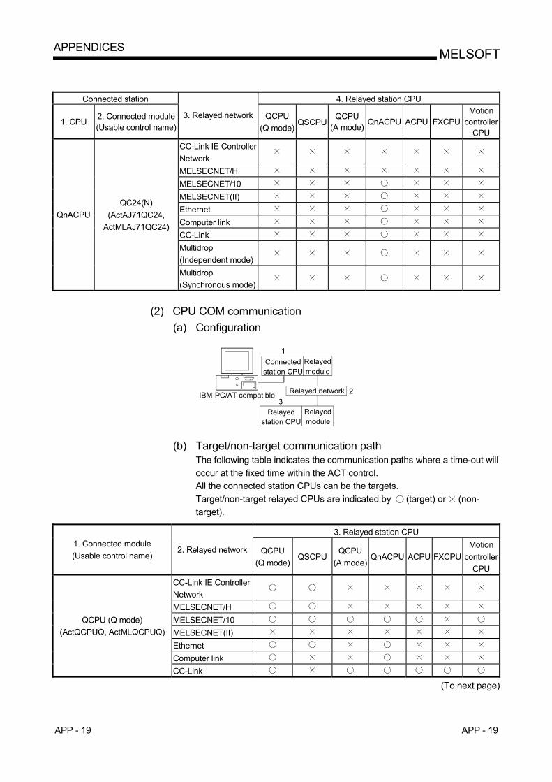
APP - 19 APP - 19
MELSOFTAPPENDICES
Connected station 4. Relayed station CPU
1. CPU 2. Connected module (Usable control name)
3. Relayed network QCPU (Q mode)
QSCPUQCPU
(A mode)QnACPU ACPU FXCPU
Motion controller
CPU CC-Link IE Controller Network
MELSECNET/H MELSECNET/10 MELSECNET(II) Ethernet Computer link CC-Link Multidrop (Independent mode)
QnACPU QC24(N)
(ActAJ71QC24, ActMLAJ71QC24)
Multidrop (Synchronous mode)
(2) CPU COM communication
(a) Configuration
IBM-PC/AT compatible
Connected station CPU
Relayedmodule
Relayed network
Relayed station CPU
Relayedmodule
1
23
(b) Target/non-target communication path
The following table indicates the communication paths where a time-out will occur at the fixed time within the ACT control. All the connected station CPUs can be the targets. Target/non-target relayed CPUs are indicated by (target) or (non-target).
3. Relayed station CPU
1. Connected module (Usable control name)
2. Relayed network QCPU (Q mode)
QSCPU QCPU
(A mode)QnACPU ACPU FXCPU
Motion controller
CPU CC-Link IE Controller Network
MELSECNET/H MELSECNET/10 MELSECNET(II) Ethernet Computer link
QCPU (Q mode) (ActQCPUQ, ActMLQCPUQ)
CC-Link
(To next page)

APP - 20 APP - 20
MELSOFTAPPENDICES
3. Relayed station CPU
1. Connected module (Usable control name)
2. Relayed network QCPU (Q mode)
QSCPUQCPU
(A mode)QnACPU ACPU FXCPU
Motion controller
CPU CC-Link IE Controller Network
MELSECNET/H MELSECNET/10 MELSECNET(II) Ethernet Computer link
QCPU (A mode) (ActQCPUA, ActMLQCPUA)
CC-Link CC-Link IE Controller Network
MELSECNET/H MELSECNET/10 MELSECNET(II) Ethernet Computer link
QnACPU (ActQnACPU, ActMLQnACPU)
CC-Link CC-Link IE Controller Network
MELSECNET/H MELSECNET/10 MELSECNET(II) Ethernet Computer link
ACPU, Motion controller CPU (ActACPU, ActMLACPU)
CC-Link CC-Link IE Controller Network
MELSECNET/H MELSECNET/10 MELSECNET(II) Ethernet Computer link
FXCPU (ActFXCPU, ActMLFXCPU)
CC-Link

APP - 21 APP - 21
MELSOFTAPPENDICES
(3) CC-Link G4 communication
(a) Configuration
2
Connected station CPU
CC-Linkmodule
Relayedmodule
Relayed network
Relayed station CPU
Relayedmodule
1
3
IBM-PC/AT compatible
CC-LinkG4module
(b) Target/non-target communication path
The following table indicates the communication paths where a time-out will occur at the fixed time within the ACT control. All the connected station CPUs can be the targets. Target/non-target relayed CPUs are indicated by (target) or (non-target).
1) When CC-Link G4-S3 module is in Q mode
3. Relayed station CPU 1. Connected module (Usable control name)
2. Relayed network QCPU (Q mode) QSCPU
QCPU (A mode)
QnACPU ACPU FXCPUMotion
controller CPU
CC-Link IE Controller Network
MELSECNET/H MELSECNET/10 MELSECNET(II) Ethernet Computer link
QCPU (Q mode) (ActCCG4Q, ActMLCCG4Q)
CC-Link
2) When CC-Link G4 module is in QnA mode
3. Relayed station CPU 1. Connected module (Usable control name)
2. Relayed network QCPU (Q mode) QSCPU
QCPU (A mode)
QnACPU ACPU FXCPUMotion
controller CPU
CC-Link IE Controller Network
MELSECNET/H MELSECNET/10 MELSECNET(II) Ethernet Computer link
QnACPU (ActCCG4QnA,
ActMLCCG4QnA)
CC-Link
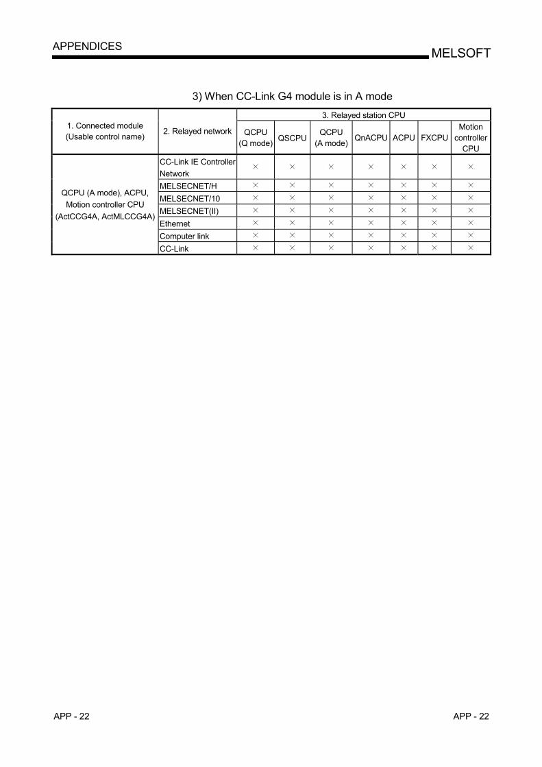
APP - 22 APP - 22
MELSOFTAPPENDICES
3) When CC-Link G4 module is in A mode
3. Relayed station CPU 1. Connected module (Usable control name)
2. Relayed network QCPU (Q mode) QSCPU
QCPU (A mode)
QnACPU ACPU FXCPUMotion
controller CPU
CC-Link IE Controller Network
MELSECNET/H MELSECNET/10 MELSECNET(II) Ethernet Computer link
QCPU (A mode), ACPU, Motion controller CPU
(ActCCG4A, ActMLCCG4A)
CC-Link

APP - 23 APP - 23
MELSOFTAPPENDICES
MEMO
WARRANTY
Please confirm the following product warranty details before using this product. 1. Gratis Warranty Term and Gratis Warranty Range
If any faults or defects (hereinafter "Failure") found to be the responsibility of Mitsubishi occurs during use of the product within the gratis warranty term, the product shall be repaired at no cost via the sales representative or Mitsubishi Service Company. However, if repairs are required onsite at domestic or overseas location, expenses to send an engineer will be solely at the customer’s discretion. Mitsubishi shall not be held responsible for any re-commissioning, maintenance, or testing on-site that involves replacement of the failed module. [Gratis Warranty Term]
The gratis warranty term of the product shall be for one year after the date of purchase or delivery to a designated place. Note that after manufacture and shipment from Mitsubishi, the maximum distribution period shall be six (6) months, and the longest gratis warranty term after manufacturing shall be eighteen (18) months. The gratis warranty term of repair parts shall not exceed the gratis warranty term before repairs.
[Gratis Warranty Range] (1) The range shall be limited to normal use within the usage state, usage methods and usage environment, etc.,
which follow the conditions and precautions, etc., given in the instruction manual, user's manual and caution labels on the product.
(2) Even within the gratis warranty term, repairs shall be charged for in the following cases. 1. Failure occurring from inappropriate storage or handling, carelessness or negligence by the user. Failure caused
by the user's hardware or software design. 2. Failure caused by unapproved modifications, etc., to the product by the user. 3. When the Mitsubishi product is assembled into a user's device, Failure that could have been avoided if functions
or structures, judged as necessary in the legal safety measures the user's device is subject to or as necessary by industry standards, had been provided.
4. Failure that could have been avoided if consumable parts (battery, backlight, fuse, etc.) designated in the instruction manual had been correctly serviced or replaced.
5. Failure caused by external irresistible forces such as fires or abnormal voltages, and Failure caused by force majeure such as earthquakes, lightning, wind and water damage.
6. Failure caused by reasons unpredictable by scientific technology standards at time of shipment from Mitsubishi. 7. Any other failure found not to be the responsibility of Mitsubishi or that admitted not to be so by the user.
2. Onerous repair term after discontinuation of production
(1) Mitsubishi shall accept onerous product repairs for seven (7) years after production of the product is discontinued. Discontinuation of production shall be notified with Mitsubishi Technical Bulletins, etc.
(2) Product supply (including repair parts) is not available after production is discontinued. 3. Overseas service
Overseas, repairs shall be accepted by Mitsubishi's local overseas FA Center. Note that the repair conditions at each FA Center may differ.
4. Exclusion of loss in opportunity and secondary loss from warranty liability
Regardless of the gratis warranty term, Mitsubishi shall not be liable for compensation of damages caused by any cause found not to be the responsibility of Mitsubishi, loss in opportunity, lost profits incurred to the user by Failures of Mitsubishi products, special damages and secondary damages whether foreseeable or not , compensation for accidents, and compensation for damages to products other than Mitsubishi products, replacement by the user, maintenance of on-site equipment, start-up test run and other tasks.
5. Changes in product specifications
The specifications given in the catalogs, manuals or technical documents are subject to change without prior notice. 6. Product application
(1) In using the Mitsubishi MELSEC programmable controller, the usage conditions shall be that the application will not lead to a major accident even if any problem or fault should occur in the programmable controller device, and that backup and fail-safe functions are systematically provided outside of the device for any problem or fault.
(2) The Mitsubishi programmable controller has been designed and manufactured for applications in general industries, etc. Thus, applications in which the public could be affected such as in nuclear power plants and other power plants operated by respective power companies, and applications in which a special quality assurance system is required, such as for Railway companies or Public service purposes shall be excluded from the programmable controller applications. In addition, applications in which human life or property that could be greatly affected, such as in aircraft, medical applications, incineration and fuel devices, manned transportation, equipment for recreation and amusement, and safety devices, shall also be excluded from the programmable controller range of applications. However, in certain cases, some applications may be possible, providing the user consults their local Mitsubishi representative outlining the special requirements of the project, and providing that all parties concerned agree to the special circumstances, solely at the users discretion.

Microsoft, Windows, Windows NT, Windows Vista, Visual Basic and Visual C++ are registered trademarks of Microsoft Corporation in the United States and other countries. Ethernet is the registered trademark of Xerox Corporation. Other company and product names herein are either trademarks of registered trademarks of their respective owners. SPREAD Copyright(C) 1999 Far Point Technologies, Inc.
SH (NA)-080272-K