Embed Size (px)
Citation preview
Thylacine-1
MWD – LWD End of Well Report

End of Well Report for Thylacine-1
Contents
• Logging Overview
• General Information
• Geomagnetic and Survey Reference Criteria
• Survey Report
• Motor Run Summary
• Bit Run Summary
• Failure Report

Logging Overview
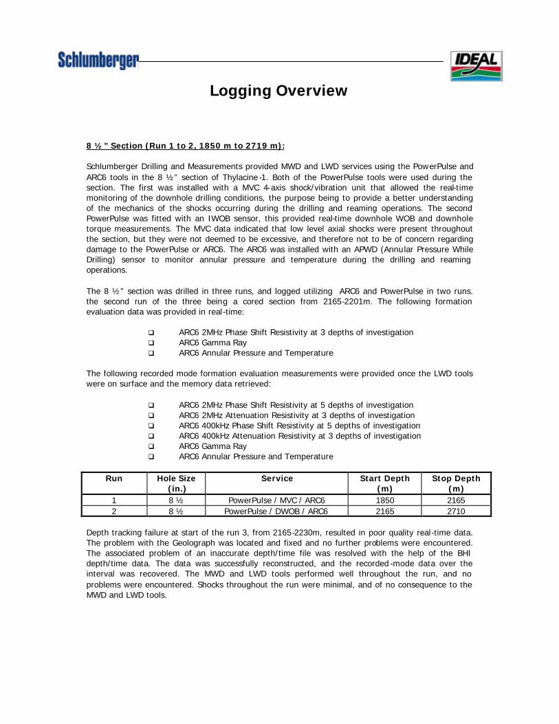
Logging Overview
8 ½” Section (Run 1 to 2, 1850 m to 2719 m): Schlumberger Drilling and Measurements provided MWD and LWD services using the PowerPulse and ARC6 tools in the 8 ½” section of Thylacine -1. Both of the PowerPulse tools were used during the section. The first was installed with a MVC 4-axis shock/vibration unit that allowed the real-time monitoring of the downhole drilling conditions, the purpose being to provide a better understanding of the mechanics of the shocks occurring during the drilling and reaming operations. The second PowerPulse was fitted with an IWOB sensor, this provided real-time downhole WOB and downhole torque measurements. The MVC data indicated that low level axial shocks were present throughout the section, but they were not deemed to be excessive, and therefore not to be of concern regarding damage to the PowerPulse or ARC6. The ARC6 was installed with an APWD (Annular Pressure While Drilling) sensor to monitor annular pressure and temperature during the drilling and reaming operations. The 8 ½” section was drilled in three runs, and logged utilizing ARC6 and PowerPulse in two runs. the second run of the three being a cored section from 2165-2201m. The following formation evaluation data was provided in real-time:
q ARC6 2MHz Phase Shift Resistivity at 3 depths of investigation q ARC6 Gamma Ray q ARC6 Annular Pressure and Temperature
The following recorded mode formation evaluation measurements were provided once the LWD tools were on surface and the memory data retrieved:
q ARC6 2MHz Phase Shift Resistivity at 5 depths of investigation q ARC6 2MHz Attenuation Resistivity at 3 depths of investigation q ARC6 400kHz Phase Shift Resistivity at 5 depths of investigation q ARC6 400kHz Attenuation Resistivity at 3 depths of investigation q ARC6 Gamma Ray q ARC6 Annular Pressure and Temperature
Run Hole Size
(in.) Service Start Depth
(m) Stop Depth
(m) 1 8 ½ PowerPulse / MVC / ARC6 1850 2165 2 8 ½ PowerPulse / DWOB / ARC6 2165 2710
Depth tracking failure at start of the run 3, from 2165-2230m, resulted in poor quality real-time data. The problem with the Geolograph was located and fixed and no further problems were encountered. The associated problem of an inaccurate depth/time file was resolved with the help of the BHI depth/time data. The data was successfully reconstructed, and the recorded -mode data over the interval was recovered. The MWD and LWD tools performed well throughout the run, and no problems were encountered. Shocks throughout the run were minimal, and of no consequence to the MWD and LWD tools.
General Information

General Information
Well Name: Thylacine-1 Rig: Diamond Offshore Ocean Bounty Field: Exploration / Permit T/30P Location: Otway Basin, Offshore Victoria Country: Australia Cell Members: Lee Muskett LWD Engineer
Anthony Strahan LWD Engineer Town Contacts: Ike Nitis Location Manager - Australia
Patrick Dassens Engineer In Charge - Victoria Company Representatives: Dennis Bell

Geomagnetic and Survey Reference Criteria
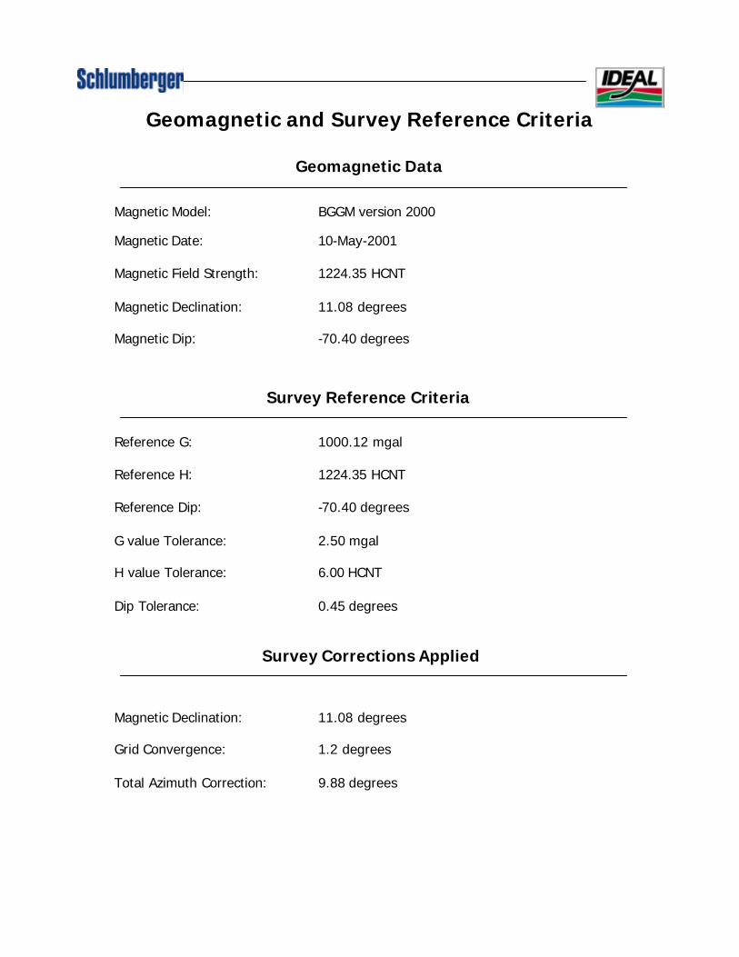
Geomagnetic and Survey Reference Criteria
Geomagnetic Data
Magnetic Model: BGGM version 2000 Magnetic Date: 10-May-2001 Magnetic Field Strength: 1224.35 HCNT Magnetic Declination: 11.08 degrees Magnetic Dip: -70.40 degrees
Survey Reference Criteria
Reference G: 1000.12 mgal Reference H: 1224.35 HCNT Reference Dip: -70.40 degrees G value Tolerance: 2.50 mgal H value Tolerance: 6.00 HCNT Dip Tolerance: 0.45 degrees
Survey Corrections Applied Magnetic Declination: 11.08 degrees Grid Convergence: 1.2 degrees Total Azimuth Correction: 9.88 degrees

Survey Report
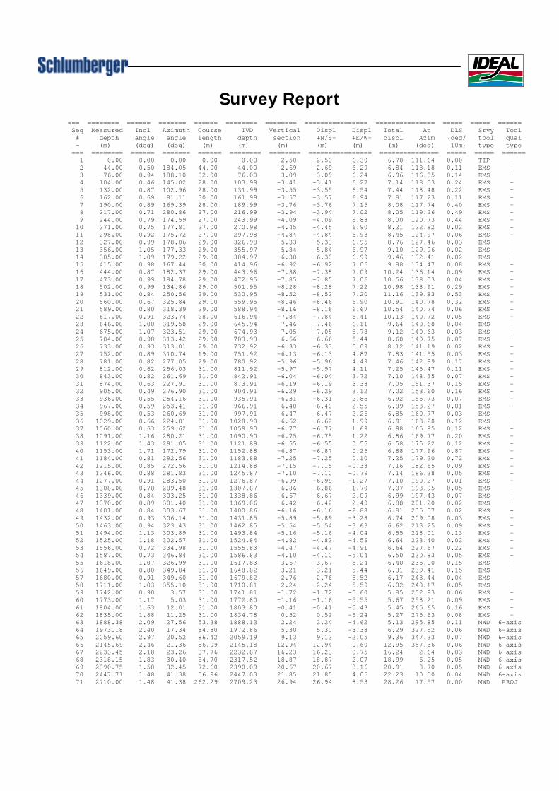
Survey Report=== ======== ====== ======= ====== ======== ======== ================ =============== ===== ===== ======Seq Measured Incl Azimuth Course TVD Vertical Displ Displ Total At DLS Srvy Tool# depth angle angle length depth section +N/S- +E/W- displ Azim (deg/ tool qual- (m) (deg) (deg) (m) (m) (m) (m) (m) (m) (deg) 10m) type type
=== ======== ====== ======= ====== ======== ======== ================ =============== ===== ===== ======1 0.00 0.00 0.00 0.00 0.00 -2.50 -2.50 6.30 6.78 111.64 0.00 TIP -2 44.00 0.50 184.05 44.00 44.00 -2.69 -2.69 6.29 6.84 113.18 0.11 EMS -3 76.00 0.94 188.10 32.00 76.00 -3.09 -3.09 6.24 6.96 116.35 0.14 EMS -4 104.00 0.46 145.02 28.00 103.99 -3.41 -3.41 6.27 7.14 118.53 0.24 EMS -5 132.00 0.87 102.96 28.00 131.99 -3.55 -3.55 6.54 7.44 118.48 0.22 EMS -6 162.00 0.69 81.11 30.00 161.99 -3.57 -3.57 6.94 7.81 117.23 0.11 EMS -7 190.00 0.89 169.39 28.00 189.99 -3.76 -3.76 7.15 8.08 117.74 0.40 EMS -8 217.00 0.71 280.86 27.00 216.99 -3.94 -3.94 7.02 8.05 119.26 0.49 EMS -9 244.00 0.79 174.59 27.00 243.99 -4.09 -4.09 6.88 8.00 120.73 0.44 EMS -
10 271.00 0.75 177.81 27.00 270.98 -4.45 -4.45 6.90 8.21 122.82 0.02 EMS -11 298.00 0.92 175.72 27.00 297.98 -4.84 -4.84 6.93 8.45 124.97 0.06 EMS -12 327.00 0.99 178.06 29.00 326.98 -5.33 -5.33 6.95 8.76 127.46 0.03 EMS -13 356.00 1.05 177.33 29.00 355.97 -5.84 -5.84 6.97 9.10 129.96 0.02 EMS -14 385.00 1.09 179.22 29.00 384.97 -6.38 -6.38 6.99 9.46 132.41 0.02 EMS -15 415.00 0.98 167.44 30.00 414.96 -6.92 -6.92 7.05 9.88 134.47 0.08 EMS -16 444.00 0.87 182.37 29.00 443.96 -7.38 -7.38 7.09 10.24 136.14 0.09 EMS -17 473.00 0.99 184.78 29.00 472.95 -7.85 -7.85 7.06 10.56 138.03 0.04 EMS -18 502.00 0.99 134.86 29.00 501.95 -8.28 -8.28 7.22 10.98 138.91 0.29 EMS -19 531.00 0.84 250.56 29.00 530.95 -8.52 -8.52 7.20 11.16 139.83 0.53 EMS -20 560.00 0.67 325.84 29.00 559.95 -8.46 -8.46 6.90 10.91 140.78 0.32 EMS -21 589.00 0.80 318.39 29.00 588.94 -8.16 -8.16 6.67 10.54 140.74 0.06 EMS -22 617.00 0.91 323.74 28.00 616.94 -7.84 -7.84 6.41 10.13 140.72 0.05 EMS -23 646.00 1.00 319.58 29.00 645.94 -7.46 -7.46 6.11 9.64 140.68 0.04 EMS -24 675.00 1.07 323.51 29.00 674.93 -7.05 -7.05 5.78 9.12 140.63 0.03 EMS -25 704.00 0.98 313.42 29.00 703.93 -6.66 -6.66 5.44 8.60 140.75 0.07 EMS -26 733.00 0.93 313.01 29.00 732.92 -6.33 -6.33 5.09 8.12 141.19 0.02 EMS -27 752.00 0.89 310.74 19.00 751.92 -6.13 -6.13 4.87 7.83 141.55 0.03 EMS -28 781.00 0.82 277.05 29.00 780.92 -5.96 -5.96 4.49 7.46 142.99 0.17 EMS -29 812.00 0.62 256.03 31.00 811.92 -5.97 -5.97 4.11 7.25 145.47 0.11 EMS -30 843.00 0.82 261.69 31.00 842.91 -6.04 -6.04 3.72 7.10 148.35 0.07 EMS -31 874.00 0.63 227.91 31.00 873.91 -6.19 -6.19 3.38 7.05 151.37 0.15 EMS -32 905.00 0.49 276.90 31.00 904.91 -6.29 -6.29 3.12 7.02 153.60 0.16 EMS -33 936.00 0.55 254.16 31.00 935.91 -6.31 -6.31 2.85 6.92 155.73 0.07 EMS -34 967.00 0.59 253.41 31.00 966.91 -6.40 -6.40 2.55 6.89 158.27 0.01 EMS -35 998.00 0.53 260.69 31.00 997.91 -6.47 -6.47 2.26 6.85 160.77 0.03 EMS -36 1029.00 0.66 224.81 31.00 1028.90 -6.62 -6.62 1.99 6.91 163.28 0.12 EMS -37 1060.00 0.63 259.62 31.00 1059.90 -6.77 -6.77 1.69 6.98 165.95 0.12 EMS -38 1091.00 1.16 280.21 31.00 1090.90 -6.75 -6.75 1.22 6.86 169.77 0.20 EMS -39 1122.00 1.43 291.05 31.00 1121.89 -6.55 -6.55 0.55 6.58 175.22 0.12 EMS -40 1153.00 1.71 172.79 31.00 1152.88 -6.87 -6.87 0.25 6.88 177.96 0.87 EMS -41 1184.00 0.81 292.56 31.00 1183.88 -7.25 -7.25 0.10 7.25 179.20 0.72 EMS -42 1215.00 0.85 272.56 31.00 1214.88 -7.15 -7.15 -0.33 7.16 182.65 0.09 EMS -43 1246.00 0.88 281.83 31.00 1245.87 -7.10 -7.10 -0.79 7.14 186.38 0.05 EMS -44 1277.00 0.91 283.50 31.00 1276.87 -6.99 -6.99 -1.27 7.10 190.27 0.01 EMS -45 1308.00 0.78 289.48 31.00 1307.87 -6.86 -6.86 -1.70 7.07 193.95 0.05 EMS -46 1339.00 0.84 303.25 31.00 1338.86 -6.67 -6.67 -2.09 6.99 197.43 0.07 EMS -47 1370.00 0.89 301.40 31.00 1369.86 -6.42 -6.42 -2.49 6.88 201.20 0.02 EMS -48 1401.00 0.84 303.67 31.00 1400.86 -6.16 -6.16 -2.88 6.81 205.07 0.02 EMS -49 1432.00 0.93 306.14 31.00 1431.85 -5.89 -5.89 -3.28 6.74 209.08 0.03 EMS -50 1463.00 0.94 323.43 31.00 1462.85 -5.54 -5.54 -3.63 6.62 213.25 0.09 EMS -51 1494.00 1.13 303.89 31.00 1493.84 -5.16 -5.16 -4.04 6.55 218.01 0.13 EMS -52 1525.00 1.18 302.57 31.00 1524.84 -4.82 -4.82 -4.56 6.64 223.40 0.02 EMS -53 1556.00 0.72 334.98 31.00 1555.83 -4.47 -4.47 -4.91 6.64 227.67 0.22 EMS -54 1587.00 0.73 346.84 31.00 1586.83 -4.10 -4.10 -5.04 6.50 230.83 0.05 EMS -55 1618.00 1.07 326.99 31.00 1617.83 -3.67 -3.67 -5.24 6.40 235.00 0.15 EMS -56 1649.00 0.80 349.84 31.00 1648.82 -3.21 -3.21 -5.44 6.31 239.41 0.15 EMS -57 1680.00 0.91 349.60 31.00 1679.82 -2.76 -2.76 -5.52 6.17 243.44 0.04 EMS -58 1711.00 1.03 355.10 31.00 1710.81 -2.24 -2.24 -5.59 6.02 248.17 0.05 EMS -59 1742.00 0.90 3.57 31.00 1741.81 -1.72 -1.72 -5.60 5.85 252.93 0.06 EMS -60 1773.00 1.17 5.03 31.00 1772.80 -1.16 -1.16 -5.55 5.67 258.21 0.09 EMS -61 1804.00 1.63 12.01 31.00 1803.80 -0.41 -0.41 -5.43 5.45 265.65 0.16 EMS -62 1835.00 1.88 11.25 31.00 1834.78 0.52 0.52 -5.24 5.27 275.63 0.08 EMS -63 1888.38 2.09 27.56 53.38 1888.13 2.24 2.24 -4.62 5.13 295.85 0.11 MWD 6-axis64 1973.18 2.40 17.34 84.80 1972.86 5.30 5.30 -3.38 6.29 327.52 0.06 MWD 6-axis65 2059.60 2.97 20.52 86.42 2059.19 9.13 9.13 -2.05 9.36 347.33 0.07 MWD 6-axis66 2145.69 2.46 21.36 86.09 2145.18 12.94 12.94 -0.60 12.95 357.36 0.06 MWD 6-axis67 2233.45 2.18 23.26 87.76 2232.87 16.23 16.23 0.75 16.24 2.64 0.03 MWD 6-axis68 2318.15 1.83 30.40 84.70 2317.52 18.87 18.87 2.07 18.99 6.25 0.05 MWD 6-axis69 2390.75 1.50 32.45 72.60 2390.09 20.67 20.67 3.16 20.91 8.70 0.05 MWD 6-axis70 2447.71 1.48 41.38 56.96 2447.03 21.85 21.85 4.05 22.23 10.50 0.04 MWD 6-axis71 2710.00 1.48 41.38 262.29 2709.23 26.94 26.94 8.53 28.26 17.57 0.00 MWD PROJ

Motor Run Summary

DOWN-HOLE MOTOR RUN REPORTFt, Mt
Motor Size : 9 5/8" Serial No : 03400 Run No : 1 BHA No: 3 Mt
Company Woodside 1 Otway Basin
Location Bass Strait Country Australia
Operator Diamond Offshore Ocean Bounty Joe Musial 8-May-01
Bit Size Make Type IADC Jets Jets Jets Jets TFA
12 1/4" Hughes BD535 7 x 12 #VALUE!o
IADC CUTTING STRUCTURE
Inner Row Outer Row Dull Char' Location Brg/Seals Gauge Others Reason for Trip
Motor Made By Size Model / Type Rotor/Stator Serial No Hsg Stab OD ° Bent Hsg ° Bent Sub
Anadrill 9 5/8" A962 GT 7:8 3400 12 1/8" n/a n/a
Type 1 = Straight; 2 = Steerable; Stator Ser Nº 3462 Rotor Ser Nº 2107 IADC Drlg Cmt, W & R 2.3
1 3 = Double Bend n/a n/a Total Motor Circ Hrs 44.6
Purpose of Run Performance drill 12.14" section to casing depth
BHA Surveys MD IN N/A Inclin - -
PDC Bit MD OUT N/A Inclin - -A962 Motor
Float Sub / XO
Roller Reamer Flow Rate Off Bttm PSI On Bttm PSI RPM WOB
Monel GPM Klbs
Roller Reamer 750-900 2900 3150 40-130 15-278 x8" DC's
1 x 8" Drilling Jars
2 x 8" DC's Aquadrill Plus Mud Wt 11.2 Mud Grad' 0.5824 Vis 59
XO
15 x HWDP PV 31 Filtrate 2.8 % Solids 12.0 Aniline Pt -
YP 43 % Oil n/a % Sand 0.25 Circ Temp 49 C
Depth In 752m Depth Out 1855m Inter'l Drld 1103m
Date In 8-May-01 Date Out 11-May-01 ROP 35.4m/hr
Time In 23:13 Time Out 3:00 Time BRT - Hrs
FAILURE? No - Previous Hrs 0.0 Cumulative Hrs 0.0
Remarks / Failure Report. Did Motor Bearing Play
1) Motor drained and checked at surface. Stall In 1mm
No Yes Out 2mm
Slide Rty Condition
NB : Top Drive Rig - 2 Good
Client Signature : Engineers Signature :
Engineer DateRig
Well Slot FieldThylacine-1
Azim
Azim
Slide Mts
IADC Circ HrsIADC Drlg Hrs
Mud Type

Bit Run Summary

MWD/LWD BIT RUN SUMMARYTA-1027-F PAGE 1 OF 2
M10 ARC ADN
SIZE DEPTH
yes no
.83 CONE LOCK GAUGE
TEETH YES NOIADC CUTTING STRUCTURE LOCATION B BRNG/SEALS G GAUGE 1/16" REMARKS
I.R. O.R. D.C. O.C.
ADV SPM IDEAL M-10 ARC ADN ISON
LWD PUMP HOURS REALTIME RECORDEDCODE PFIX SN CODE PFIX SN START CUM HRS FAIL FT/M HRS FAIL FT/M
MDC ARC6 ARC GR
MMA ARC RES
MEC APWD ARC APWD
MTA DWOB
DTOR
MVC MWD D&I
MVC
MEXD
CDR GR
CDR RES
NEUT
DENS
DSS DLS DRS ARC ADN
DSW DLW DRW DTS DTW GST
READ - OUT - PORT TO BIT
M-10 ARC ADN
CHECK SHOT TYPE:
DEPTH: INCL: AZI:
OPERATING CONDITIONS LCMAVG ROP AVG RPM AVG PP AVG GPM END VIS END MUD WT. END MUD RES. MUD ADDITIVES LCM
LCM HEMATITE TYPE:BIT/SEC / FREQ MAX CIRC TEMP AVG WOB AVG TORQ MAX MWD SHK MAX SHK DUR. TDH SHOCK BEADS GILSONITE SIZE:
NONE BARITE CONC: lb/bbl
MUD F-H2O L-LIG O-OIL% S-SALT H2O MUD CLEAN SAND % SOLID % BHA B-BUILD M-MOTOR S-STEERABLE
TYPE K-KCL M-LIM P-POLYMER X- HYDENS YES NO TYPE H-PACKED HOLEMILL P-PENDULUM X-LOGGING
TURBINE CONFIGURATION JAMMING TOOL JAMMING SYNC TIME BIT D-DIAMOND P-PDC A -PDC-A MOD IMPULSE M3
YES NO TIME: 0 MINS. TYPE I-INSERT M-MILL TOOTH X - TYPE S-SINUSOIDAL M10
COLLAR NOISE PROBLEMS PRES INC AT FLOAT SUB LOST RIG TIME SURFACE SYSTEM TRIP TERMINATION CLIENT SURFACE BHA SURFACE
NORMAL SURFACE NONE FAILURE YES DUE TO MWD FAILURE DUE DIRECTLY TO MWD INCONVENIENCE VIBRATION VIBRATION SCREEN
OTHER DOWNHOLE YES NO NO - HRS. YES NO YES NO YES NO YES NO YES NO YES NO
SUMMARY
42.5
-
27.6
losses while on bottom drilling due to surface noise (mud pumps). When this occurred the situation was easily resolved, pickup off bottom, cycle pumps and the signal
returned. The problem disappeared during the last 3 hours of the run, however, the company man request that we pickup the backup MWD tool for run 2.
74 4
1.5
Good signal from the MWD for real-time logging data, minimal shocks recorded and good quality recorded mode logging data. Plauged by intermittent and sudden signal
17.6 m 120 640
242424242424
3850
400 - 800 -
6.0/24 Hz Level 110
73 sec 1.26 sg 0.084
0N 0 N
N 0
00
N 0 00
310
206N24 45310N
310 45 N 310AA 098 24 N
BB 57031024 N 310 45198145 0 24
24 N 310 45BB 412 24BB 612
id6.1c_03 -
24 N087 0 24AB 066START CUM
24
MWD PUMP HOURS
310REAS. PULLED BOT HRS
CP 21.4
4.3gal. TRI
id6.1c_03
17.6PUMP OUTPUT/TYPE JETS/TFA LWD DRILL HOURS
4x16 / 0.785 in2
10.48 3.75/3.83/3.14 4726LWD DRILL FT/M
645 0.0 0.0630 4765TUR RPM/FLOW MAX
31023.9LWD REAM HOURS LWD REAM FT/M
12.83 0.08 n/aBIT TO MD RES/GR/APWD TUR RPM/FLOW MINBIT TO SLICK PIN
FT/M DRILLED
23.9 310BENT HOUSING ANGLE PUMPING HOURS
n/aRT TRANS FT/M
Rot.MVC/ARC/APWD 11.08 / 1.2 n/a n/aTRANS FAIL RT TRANS HOURSBIT-TO-SURVEY MODULATOR GAP BENT SUB ANGLE
FRAME FORMAT MAG DEC/GRID CONV: T/F ARC T/F ANGLE
Otway Basin Permit No. T/30P 8.5" 101.4/25.0 m n/aLOCATION HOLE SIZE WATER DEPTH/AIR GAP DOWNHOLE MOTOR TYPE/SIZE/SN
Thylacine-1 21.4 Hughes / MCH08 / 1905297
1849.5mWELL NAME AZIMUTH - FROM TO BIT MFG/MODEL/IADC CODE
Diamond Offshore Ocean Bounty 2.46 9 5/8"
-RIG NAME DRIFT - FROM TO LAST CASING
Woodside Energy Limited 21651855
2.09
ASQ-01 D.Bell 115-May-0113-May-01COMPANY HOLE DEPTH - FROM TO COLLAR SIZE
1 3
6 3/4"
A.Strahan
6 3/4"
CELL MGR.JOB NUMBER COMPANY REP. DATE IN DATE OUT MWD RUN NO. LWD RUN NO. RIG BIT RUN NO.
XA InWT11 2xCTSOFTWARE VERSION LWD BRT HRS.
- 6.1B 6.3B -
45 N 310
N 310
310
N
- 48
11.5
0
10.48 4.97
0
000
0

PAGE 2 OF 2
DOG Sub
STABILIZER DESCRIPTION DISTANCE BLADE BLADE BLADE GAUGE GAUGE GAUGE BHA DATA
MID PT. TO BIT TYPE LENGTH WIDTH LENGTH IN OUT PREDICTED BHA TENDENCY
FIELD PRESENT AVERAGE AVERAGE DESURGER TUR RPM AVERAGEDATE ROP S.P. PRS. CHG. (PSI) AT ROTARY SHOCK LOG
ENGR DEPTH (M/HR) (PSI) GPM (RPM) MAX
#1 #2 CY-1 TCY-1 SHOCK TDH
AVG/MAX AVG/MAX AVG/MAX AVG/MAX DRAG MUD MUD Rm SIGNAL NOISETIME DWOB SWOB DTOR STOR FRIC UP/ WEIGHT VIS OHM/M STRENGTH MARGIN
(K lbs) (K lbs) (K lbs) (K lbs) DOWN (SG) (SEC) @ TEMP (MV)(PSI)
3.5
3.5
3.5
4 1/2 Reg
4 1/2 IF
5 1/2 FH
5 1/2 FH
4 1/2 IF
8.5
6.75
2.25
X/O
PBL Sub
2x6 1/2 DC
0.18
MWD
Surface Makeup BHA.
14-May-01
1859m
Drilling new formation.
06:30 1859m
07:09
04:20
17:00
TIME
4 1/2 IF
6.5 4 1/2 IF
9.6718.75
3.5
harmonics. The effects were instant, but easily
Flowrate was 675gpm. Status word on MWD
Drilling new formation.
4 1/2 IF
6 1/2 DC
4 1/2 IF
6.75
6.75
6.75 3.5
2 13/16
n/a
136.78
12x6 1/2 DC
Jars
12FINAL
-
- -- -
1.261.26
- - -1.26
-3947 476514-May-01 LM 2042 43 1000 1000
4 1/2 IF
4 1/2 IF2 13/166.5
6.75
2.47 6.75
1.82 6.75
0.46 6.75
13:20 Surface
immediately cycled pumps and regained signal
Situation happened several more times, but
Lost 2m of RT data. SPT 1&2 signal strength
and ARC both zero. Drill ahead with 640gpm.
while drilling prior to demod . problems
Download ARC data while in RT, place magnet
fixed by picking up off bottom, cycle pumps.
21:00, 21:30, 22:10, 23:19, 1:20, 2:20, 3:16, 4:30.
quality before continuing ahead. Cause unknown
but suspect pumps/lines problem at surface.
problem at 14:30, 16:30, 17:00, 17:30, 20:00, 20:30,
Continue to pickup and cycle pumps due to
problems with demodulation. Occurences of
MWD RUN NO.
1LWD RUN NO.
1
ITEM
3.5
unable to decode on SPM due to massive uphole
MWD demod. (SPT1&2 signal strength 2.5 & 1psi)
Rm=0.084, Rmf=0.0724, Rmo=0.1286 at 28degC.
5.48
13-May-01
Circulate hole clean, conduct FIT.
Float
6.751.48
0.35SHT at 500gpm.
Drill out float and shoe.
DATE
-
LENGTH
TOTAL
6.2n/a 6.7n/a18 -
-23:00 -02:41 -
--
804
- -80
3
FINAL
4 8581.25 6213:45 - 8n/a -07:50 - 10 - 4
38-639 -11821125 - - -10
14-May-01 AS 1920 12 3805 1000 1000 4765 64580 - - -14-May-01 LM 1864 8.1
associated with reduction in pump harmonics
after a connection. No more demod. Problems.
Flowrate steady between 630-665gpm.
4072643 1000 1000 -
2030m22:10
12:00 1910m
is much stronger, on average 8psi and 3psi for
SPT1&2 respectively.
11:00 1891m
10:30 1880m
LENGTH ODBHA DESCRIPTION
Surface
1855m
00:30 1821m
ASQ-01
15:59
Surface18:15
DEPTH
4 1/2 IF
COMMENTS
-0.29 8.5
5 1/2 FH
5 1/2 FH
4 1/2 IF9.36
ID CONN4 1/2 Reg
309.66
6.75
3.5
3.5
3.5
3.5
4 1/2 IF
ARC6
X/O
0.92 6.5
3.5
JOB NO.
Roll.Reamer
ILS
6.757.49
112.05
15xHWDP
0.49
PDC Bit
Stab. 1.62 6.75
342 memory Fill hours.
ARC initilised. Config. GR/2MHz/400KHz 5secs.
XO
3.5
Bit Sub
Sudden improvement in signal quality. This was2131m05:1015-May-01
07:10 2165m
and POOH.
in ROP and rack back in derrick.
Reached coring point. Circulate bottoms up
15-May-01 LM 2088 24 3818 1000 1000 4726 - 48630 123 - -

MWD/LWD BIT RUN SUMMARYTA-1027-F PAGE 1 OF 2
M10 ARC ADN
SIZE DEPTH
yes no
.83 CONE LOCK GAUGE
TEETH YES NOIADC CUTTING STRUCTURE LOCATION B BRNG/SEALS G GAUGE 1/16" REMARKS
I.R. O.R. D.C. O.C.
ADV SPM IDEAL M-10 ARC ADN ISON
LWD PUMP HOURS REALTIME RECORDEDCODE PFIX SN CODE PFIX SN START CUM HRS FAIL FT/M HRS FAIL FT/M
MDC ARC6 ARC GR
ARC RES
MEC APWD ARC APWD
DWOB
MGD DTOR
MWD D&I
MEXD MVC
MWD D&I
CDR GR
CDR RES
NEUT
DENS
DSS DLS DRS ARC ADN
DSW DLW DRW DTS DTW GST
READ - OUT - PORT TO BIT
M-10 ARC ADN
CHECK SHOT TYPE:
DEPTH: INCL: AZI:
OPERATING CONDITIONS LCMAVG ROP AVG RPM AVG PP AVG GPM END VIS END MUD WT. END MUD RES. MUD ADDITIVES LCM
LCM HEMATITE TYPE:BIT/SEC / FREQ MAX CIRC TEMP AVG WOB AVG TORQ MAX MWD SHK MAX SHK DUR. TDH SHOCK BEADS GILSONITE SIZE:
NONE BARITE CONC: lb/bbl
MUD F-H2O L-LIG O-OIL% S-SALT H2O MUD CLEAN SAND % SOLID % BHA B-BUILD M-MOTOR S-STEERABLE
TYPE K-KCL M-LIM P-POLYMER X- HYDENS YES NO TYPE H-PACKED HOLEMILL P-PENDULUM X-LOGGING
TURBINE CONFIGURATION JAMMING TOOL JAMMING SYNC TIME BIT D-DIAMOND P-PDC A -PDC-A MOD IMPULSE M3
YES NO TIME: 0 MINS. TYPE I-INSERT M-MILL TOOTH X - TYPE S-SINUSOIDAL M10
COLLAR NOISE PROBLEMS PRES INC AT FLOAT SUB LOST RIG TIME SURFACE SYSTEM TRIP TERMINATION CLIENT SURFACE BHA SURFACE
NORMAL SURFACE NONE FAILURE YES DUE TO MWD FAILURE DUE DIRECTLY TO MWD INCONVENIENCE VIBRATION VIBRATION SCREEN
OTHER DOWNHOLE YES NO NO 0 HRS. YES NO YES NO YES NO YES NO YES NO YES NO
SUMMARY
MWD RUN NO. LWD RUN NO. RIG BIT RUN NO. CELL MGR.
2JOB NUMBER COMPANY REP. DATE IN DATE OUT
ASQ-01 D.BellCOMPANY
Woodside Energy LimitedRIG NAME
Diamond Offshore Ocean BountyWELL NAME
16-May-01 19-May-01 2 5 A.StrahanHOLE DEPTH - FROM TO COLLAR SIZE
N 31024 N 310 45
2201 2710 6 3/4" 6 3/4"
565
565
565
565
71
71
N
N
N
N
565
565
46
46
24 NN 310 45
N71565
0
0
0
10.47 4.96
15.00.0
-
Good signal from MWD for real-time logging data, minimal shocks recorded and good quality recorded mode logging data.
Depth tracking failure at the start of run (during reaming section and the start of drilling).
- 75
-LAST CASING
9 5/8" 1849.5mBIT MFG/MODEL/IADC CODE
Hughes / MCH08 / 1905297DOWNHOLE MOTOR TYPE/SIZE/SN
71 N 565
N
68.8
565
SOFTWARE VERSION LWD BRT HRS.
- 6.1B 6.3B -
N
WT22
DRIFT - FROM TO
2.46
Thylacine-1 41.4AZIMUTH - FROM TO
1.48
8.5" 101.4/25.0 m n/aLOCATION HOLE SIZE WATER DEPTH/AIR GAP
Otway Basin Permit No. T/30PFRAME FORMAT MAG DEC/GRID CONV: T/F ARC T/F ANGLE
RT TRANS FT/M
11.08 / 1.2 n/a n/aTRANS FAIL RT TRANS HOURSBIT-TO-SURVEY MODULATOR GAP BENT SUB ANGLE
Rot.IWOB/ARC/APWD
FT/M DRILLED
45.5 509BENT HOUSING ANGLE PUMPING HOURS
n/a
12.82 0.08 n/aBIT TO MD RES/GR/APWD TUR RPM/FLOW MINBIT TO SLICK PIN TUR RPM/FLOW MAX
56545.5LWD REAM HOURS LWD REAM FT/M
10.47 3.74/3.82/3.13 3101LWD DRILL FT/M
600 2.6 56580 3242PUMP OUTPUT/TYPE JETS/TFA LWD DRILL HOURS
4x12 / 0.442 in2
PUMP HOURS
4.3gal. TRI
id6.1c_03
XA 1/16
509REAS. PULLED BOT HRS
TD 25.0
26.7
No
46 N087 24 70
435
id6.1c_03 -
AC Y752START CUM
46
MWD
N 565 7146
198145 24 70 N 565 7146
46 N46 565
310
0
N 0 00
N
N 0
000 N 0
-
72 sec 1.33 sg 0.10219.1 m
400 - 800
Level 1186.0/24 Hz 81 6
21.4
464646
4646
4000120 600
PAGE 2 OF 2
DOG Sub
STABILIZER DESCRIPTION DISTANCE BLADE BLADE BLADE GAUGE GAUGE GAUGE BHA DATA
MID PT. TO BIT TYPE LENGTH WIDTH LENGTH IN OUT PREDICTED BHA TENDENCY
FIELD PRESENT AVERAGE AVERAGE DESURGER TUR RPM AVERAGEDATE ROP S.P. PRS. CHG. (PSI) AT ROTARY SHOCK LOG
ENGR DEPTH (M/HR) (PSI) GPM (RPM) MAX
#1 #2 CY-1 TCY-1 SHOCK TDH
AVG/MAX AVG/MAX AVG/MAX AVG/MAX DRAG MUD MUD Rm SIGNAL NOISE
TIME DWOB SWOB DTOR STOR FRIC UP/ WEIGHT VIS OHM/M STRENGTH MARGIN
(K lbs) (K lbs) (K lbs) (K lbs) DOWN (SG) (SEC) @ TEMP (MV)
(PSI)
TOTALLENGTH 309.66
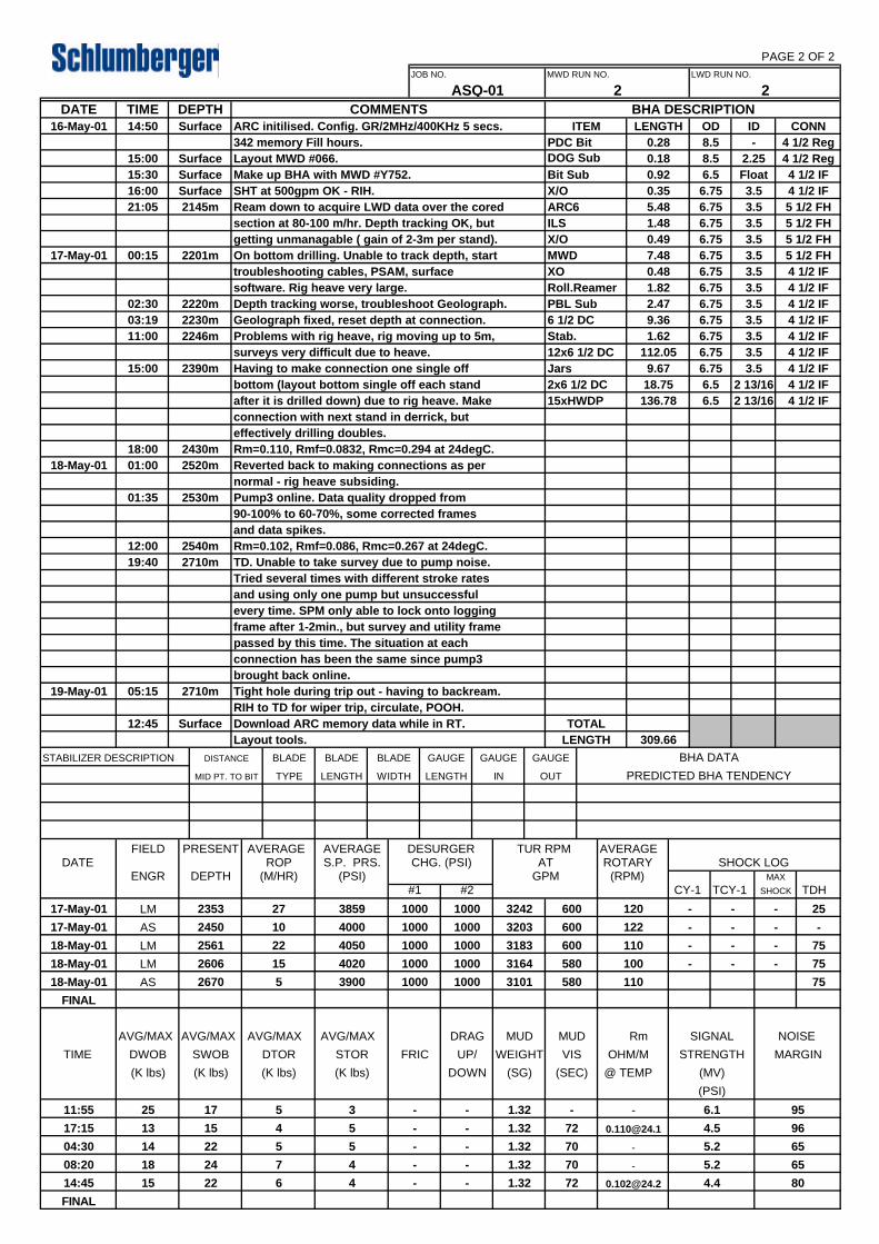
19-May-01 05:15 2710m Tight hole during trip out - having to backream.brought back online.connection has been the same since pump3
frame after 1-2min., but survey and utility framepassed by this time. The situation at each
and using only one pump but unsuccessfulevery time. SPM only able to lock onto logging
TD. Unable to take survey due to pump noise.Tried several times with different stroke rates
19:40 2710m
and data spikes.12:00 2540m Rm=0.102, Rmf=0.086, Rmc=0.267 at 24degC.
Pump3 online. Data quality dropped from 90-100% to 60-70%, some corrected frames
01:35 2530m
Reverted back to making connections as pernormal - rig heave subsiding.
18-May-01 01:00 2520m18:00 2430m
Layout tools.12:45 Surface Download ARC memory data while in RT.
RIH to TD for wiper trip, circulate, POOH.
ARC initilised. Config. GR/2MHz/400KHz 5 secs.
XO
3.5Bit Sub
342 memory Fill hours. PDC Bit
Stab. 1.62 6.75
ILS
6.757.480.49 6.75
136.78
12x6 1/2 DC
1.48 6.75
6.56.75
JOB NO. MWD RUN NO.
ARC6X/O
0.92
ASQ-01 2COMMENTS BHA DESCRIPTION
ITEM
3.53.53.53.53.5
6.756.75
ID CONN4 1/2 Reg
4 1/2 IF
-0.28 8.5
5 1/2 FH5 1/2 FH
4 1/2 IF9.36
2145m16:00 Surface
SurfaceSurface
LENGTH OD
17-May-01 00:15 2201m
2220m02:3003:19
2246m11:002230m
15:00 2390m
after it is drilled down) due to rig heave. Makeconnection with next stand in derrick, but
TIME DEPTH
6003859 1000 1000 324217-May-01 LM 2353 27 120 - - - 25
17-May-01 AS 2450 10 4000 1000 1000 3203 600 -122 - - -
75-600
580 - 75
110 - -
100
580 110 75
- -
FINAL
11:55 25 17 5
5 964.51.32 72 [email protected] -17:15 13 15 4
70
65
72 80
- 5.2 65
70 - 5.2
5
- -4
1.32
1.32
- -04:30 14
08:20 18
22 5
724
DATE
-
16-May-01 14:50
section at 80-100 m/hr. Depth tracking OK, but
Float0.35
Make up BHA with MWD #Y752.SHT at 500gpm OK - RIH.
Surface
15:30
software. Rig heave very large.troubleshooting cables, PSAM, surface
6.75
6.5
6.752.47 6.75
On bottom drilling. Unable to track depth, start
5.48
Geolograph fixed, reset depth at connection.
Having to make connection one single offsurveys very difficult due to heave.
bottom (layout bottom single off each stand
0.481.82
LWD RUN NO.
2
0.18 8.5 2.25
3.5112.05
15xHWDP
3.5Jars 9.67
15:00
21:05
Rm=0.110, Rmf=0.0832, Rmc=0.294 at 24degC.effectively drilling doubles.
Layout MWD #066.
Ream down to acquire LWD data over the cored
getting unmanagable ( gain of 2-3m per stand).
Depth tracking worse, troubleshoot Geolograph.
Problems with rig heave, rig moving up to 5m,
4 1/2 Reg4 1/2 IF4 1/2 IF
6.75 3.5 5 1/2 FH
4 1/2 IF
4 1/2 IF2 13/16
3.52 13/16 4 1/2 IF
18-May-01
4050 318318-May-01 LM
LM
2561 22
31642606 15 4020
1000 1000
1000 1000
18-May-01 AS 2670 5
951.32
3900 1000 1000 3101
3 - 6.1- -
1.3214:45 15 22 6 4 - -
3.5 5 1/2 FHX/O 3.5MWD
6.75 4 1/2 IFRoll.ReamerPBL Sub 4 1/2 IF6 1/2 DC
4 1/2 IF4 1/2 IF
2x6 1/2 DC 18.75 6.5
FINAL
Failure Reports

FAILURE REPORT Schlumberger Anadrill FR No. : 1 Company : Woodside Energy Ltd. Rig : Ocean Bounty Failure date : 14-5-2001 Well : Thycaline 1 District : ASQ Job No. : ASQ-01 Cell Mgr. : A.Strahan Service : MWD & ARC/APWD Run No. : 1 EQUIPMENT & SERIAL No. : Powerpulse MEC 612-BB, Dhsftware 6.1B08, Ideal 6.1C-03 FAILURE DESCRIPTION & SYMPTOMS (Include software version if applicable) Telemetry Mode: 24Hz / 6bps / BPSK While drilling formation the demodulation screen displayed a series of “zero’s” for the d-points within the rotary frame, this was then followed by zero demodulation. However, DSPScope continued to show a signal being transmitted from the tool, and the SPT’s also indicated this to be true. The SPM was unable to gain “sync”, this resulted in pulling off bottom and cycling the pumps. Immediately prior to the failure the flow rate was approx. 690 gpm, mud weight 1.26 sg, and SPT1 was demodulating at approx. 12 psi. However, the flow rate had been increased considerably to accommodate the required drilling parameters, and this was reflected by an increase in both the TRPM and signal strength. At the time of failure the TRPM remained constant and therefore removed the possibility of a washout above the MWD tool, however, the signal strength deteriorated down to approx. 3 psi. The cross-correlation plots indicate pump noise, and the pump harmonics did encroach into the bandwidth at the time of failure and in general there was considerable noise across the entire range of frequencies. Additionally, on more than one occasion the subsequent failures coincided with a loss of pressure on the rig floor. Failure Group : Failure Category : Completed by : Lee Muskett Date : 14-5-01 REMEDIAL ACTION ATTEMPTED ON LOCATION Initially forced retraining of the Equalizer Control was applied, but this failed to regain the sync. Therefore, the driller was instructed to pull off bottom and circulate the pumps, this instantly rectified the problem and the signal strength returned to normal. Additionally, the bandwidth was reduced to filter any pump harmonics that may develop on the lower side of the bandwidth, and the pressure of the Pulsation Dampeners was re-checked. Flow rates were also limited to 640 gpm. Periodically for the next 18 hours the same scenario would occur several times, each time it was corrected by cycling the pumps. At the end of the well Pump3 was given a service. It was found the pulsation dampener couldn’t hold pre-charge (750psi) and had to be replaced. Completed by : Lee Muskett Date : 14-5-01 FAILURE ANALYSIS (For completion during R&M repair) Incoming System Test performed upon receiving this tool: total pumping time=38.5 hours, total shocks=390 above 25G. No jamming recorded (physical or electronical) inside tool’s Repair & Maintenance memory Tool tested and is fully functional with no problems found. Failure Category : Completed by : Anthony Iemma Date : 25-5-01 ACTION FOLLOW UP (For completion by FSM / DTM) MWD worked OK throughout the run. Engineers recorded the pre ssure trace from the tool during the run showing that outside factors were influencing signal quality. Tests performed by technicians in the shop confirmed that tool is functioning OK. Tool’s memory did not record any problems: only small number of shocks was present, no jamming recorded throughout the run, either physical obstruction e.g. cement chunks or electrical problem. This would have been recorded in the tool’s memory as an anti-jamming operation when the tool attempts to restart. None of it was present, indicating that tool was operating OK throughout the run. Total operating time (tool operates only when pumps are on) agrees with the total circulating time recorded by Schlumberger and checked with mudloggers. This confirms that the tool was operational throughout the whole run without being off for more then the normal time during connections. Engineers to ensure that all surface rig equipment, mainly pumps and pump bladders are checked and operational and problems associated with nonconformity with this requirement communicated to Client and drilling contractor. Completed by : H. Spoljaric Date : 29-5-01 Always Distribute with BRS and/or BHA Summary : CELL File (Fax to town) R&M (R&M Diagnosis −> Maintenance file)
R&M (R&M Diagnosis −> CELL) FSM (Action plan −> UNIT) NOTE : Failure reports must also be sent in with failed equipment.
CHECK LIST: Anadrill Management notified ? Equipment marked RONG ? Full function test after repair ? History card filled in ? This FR returned to CELL ? Any calibra tion data to attach ?
Y
Y

MWD #1 NOISE PROBLEMS AFFECTING SIGNAL QUALITY MWD#2 NOISE PROBLEMS AFTER PUMP#3 WAS BROUGHT ONLINE TOWARDS END OF RUN

FAILURE REPORTSchlumberger Anadrill
FR No. : 2
Company : Woodside Energy Ltd. Rig : Ocean Bounty Failure date : 16/17-5-2001Well : Thycaline 1 District : ASQ Job No. : ASQ-01Cell Mgr. : A.Strahan Service : MWD & ARC/APWD Run No. : 2EQUIPMENT & SERIAL No. : GeolographFAILURE DESCRIPTION & SYMPTOMS (Include software version if applicable)Coring of the Upper Waare Formation was undertaken between 2165m and 2201m MD. BHA for the next run was thenpicked up and RIH, with the LWD tool being utilized to ream down through the cored section, and then to continuedrilling/logging to TD. The failure of the Geolograph resulted in the loss of accurate RT data, and possibly RM data,between 2162m and 2227m (65m).
The Geolograph was attached to the Top Drive, prior to the commencement of reaming. For the first 2 singles reamed thedepth was checked and found to be tracking well, only 0.39m ahead of the drillers pipe tally. However, from this pointonwards the depth, which was checked at each single, progressively became worse, tracking faster than the pipe tally(gaining depth). In addition to tracking fast, the problem was made seemingly more complex by the fact that the Geolographwould indicate stand lengths of 15-20m’s instead of approx. 29m.
Failure Group : Failure Category : Completed by : Lee Muskett Date : 17-5-01REMEDIAL ACTION ATTEMPTED ON LOCATIONThe Geolograph wire was checked and its operation was found to be smooth and seemingly in good working order. The highwinds were a concern, but similar conditions had previously been encountered and the unit had operated without anyproblems. Ideal was closed down and re-booted for the reason to check if the calibration file had become corrupted, but thishad no effect, and the rest of the system continued to work fine. The depth continued to increase at an accelerated rate. Theencoder emulator was attached to the UCS cable at the Geolograph; this worked without any problems and thereforeeliminated both Ideal, PSAM and the UCS cabling from the problem. The Geolograph covers were removed and the encoderremoved from revolving shaft that physically connects the pulley system to the encoder. The shaft that protrudes from theencoder was then rotated three times (3ft) and the distance noted on Ideal, this proved to be accurate and thereforeeliminated the encoder from the problem. It was noted that the grub screw that connects the two shafts together was loose,and therefore that the two may well be moving independently of each other. The screw was re-fitted with loctite, and theGeolograph re-assembled. This proved to be the only problem, and depth was tracked accurately from that point onwards.
Completed by : Lee Muskett Date : 17-5-01FAILURE ANALYSIS (For completion during R&M repair)N/A
Failure Category : Completed by : Date :ACTION FOLLOW UP (For completion by FSM / DTM)This was a one-off incident. Engineers to ensure pre-job checks are performed including verifying proper operation ofsensors. With this particular sensor, checks to include visual inspection to grab screw and applying fresh loctite to it asnecessary, checking the wire line, air motor and its operation, motor’s lubricant fluid levels, hoses and cables and mostimportantly, backup sensor and other critical parts (motor, line, air regulator) always to be available on site.
Completed by : H.Spoljaric Date : 25-5-01Always Distribute with BRS and/or BHA Summary :CELL File (Fax to town)R&M (R&M Diagnosis ✍✞ ✝Maintenance file)R&M (R&M Diagnosis ✍✞ ✝CELL)FSM (Action plan ✍✞ ✝UNIT)
NOTE : Failure reports must also be sent in with failed equipment.
CHECK LIST:Anadrill Management notified ?Equipment marked RONG ?Full function test after repair ?History card filled in ?This FR returned to CELL ?Any calibration data to attach ?