Embed Size (px)
Citation preview

Cat.No.R50E-14
MurataManufacturing Co., Ltd.
Trimmer Potentiometers/Rotary Position Sensors
• This PDF catalog is downloaded from the website of Murata Manufacturing co., ltd. Therefore, it’s specifications are subject to change or our products in it may be discontinued without advance notice. Please check with our sales representatives or product engineers before ordering.
• This PDF catalog has only typical specifications because there is no space for detailed specifications. Therefore, please approve our product specifications or transact the approval sheet for product specifications before ordering.
!Note R50E.pdf05.9.9

CONTENTS
!Note • Please read rating and !CAUTION (for storage, operating, rating, soldering, mounting and handling) in this catalog to prevent smoking and/or burning, etc.• This catalog has only typical specifications because there is no space for detailed specifications. Therefore, please approve our product specifications or transact the approval sheet for product specifications before ordering.
Recycled Paper
1
2
3
4
5
6
7
8
9
10
Part Numbering 2
Selection Guide of Trimmer Potentiometers 5
SMD Open Type 2mm Size PVZ2/PVA2 Series 6
PVZ2/PVA2 Series Notice 10
SMD Open Type 3mm Size PVZ3/PVS3/PVA3 Series 12
PVZ3/PVS3/PVA3 Series Notice 19
SMD Sealed Type 2mm Size PVF2 Series 22
PVF2 Series Notice 24
SMD Sealed Type 3mm Size PVG3 Series 26
PVG3 Series Notice 29
SMD Sealed Type 4mm Size PVM4 Series 31
PVM4 Series Notice 33
SMD Sealed Type Multi-turns PVG5/PV01 Series 36
PVG5/PV01 Series Notice 40
Lead Sealed Type Single-turn PVC6/PV32/PV34 Series 42
PVC6/PV32/PV34 Series Notice 52
Lead Sealed Type Multi-turns PV12/PV37/PV23/PV22/PV36 Series 54
PV12/PV37/PV23/PV22/PV36 Series Notice 67
Rotary Position Sensors SMD/Lead Dust-proof Type 12mm Size SV01 Series 69
SV01 Series Notice 71
Rotary Position Sensors Connector Dust-proof Type SV21 Series 73
SV21 Series Notice 74
SMD Open Type (PVZ2/A2/Z3/S3/A3)/SMD Sealed Type (PVM4A_C01 Series) Specifications and Test Methods 75
SMD Sealed Type (PVF2/G3/M4A_D01/G5/01)/Lead Sealed Type (PVC6/32/34/12/37/23/22/36) Specifications and Test Methods 77
Rortary Position Sensors SMD/Lead Dust-proof Type (SV01) Specifications and Test Methods 80
Rortary Position Sensors Connector Dust-proof Type (SV21) Specifications and Test Methods 81
Packaging 82
Recommended Adjustment Tools/Qualified Standards 87
1
2
3
4
5
6
7
8
9
10• The RoHS compliance means that we judge from EU Directive 2002/95/EC the products do not contain lead, cadmium, mercury, hexavalent
chromium, PBB and PBDE, except exemptions stated in EU Directive 2002/95/EC annex and impurities existing in natural world.• This statement does not insure the compliance of any of the listed parts with any laws or legal imperatives developed by any EU members
individually with regards to the RoHS Directive.
• This PDF catalog is downloaded from the website of Murata Manufacturing co., ltd. Therefore, it’s specifications are subject to change or our products in it may be discontinued without advance notice. Please check with our sales representatives or product engineers before ordering.
• This PDF catalog has only typical specifications because there is no space for detailed specifications. Therefore, please approve our product specifications or transact the approval sheet for product specifications before ordering.
!Note O63E.pdf05.9.9

!Note • Please read rating and !CAUTION (for storage, operating, rating, soldering, mounting and handling) in this catalog to prevent smoking and/or burning, etc.• This catalog has only typical specifications because there is no space for detailed specifications. Therefore, please approve our product specifications or transact the approval sheet for product specifications before ordering.
2
o Part Numbering
qProduct ID
Trimmer Potentiometers
PV Trimmer Potentiometers
Product ID
(Part Number)
wSeries
eAdjustment Direction /Lead Type
Code Series CodeAdjustment Direction/
Lead Type
Z2SMD Open 2mm Size
Carbon Resistive Element
A2 SMD Open 2mm Size
A
K
Top
A Top
Rear
R Rear
Z3
S3
G3
A3
F2
M4
01
C6
G5
SMD Open 3mm SizeCarbon Resistive Element
SMD Open 3mm Size
SMD Sealed 4mm Size
SMD Sealed 6mm Square12-turns
32Lead Sealed 6mm Round
Single-turn
34Lead Sealed 9mm Square
Single-turn
12Lead Sealed 7mm Round
4-turns
Lead Sealed 6mm SquareSingle-turn
SMD Sealed 5mm Square11-turns
SMD Sealed 3mm Size
SMD Sealed 2mm Size
SMD Open 3mm SizeStopper Low-profile
A
A
A
A
A
A
H
P
W
X
A
D
E
G
H
M
Q
H
P
R
N
T
S
F
P
H
X
W
H
P
T
S
G
K
A
Top
Top
Top
Top
Top
Side
Side
Top
Side
Top, Triangle
Top, Triangle
Side, Triangle
Side, Triangle
Side, Triangle
Top, Inline
Side, Inline
Top, Triangle
Top, Triangle
Top, Inline
Side, Triangle
Side, Triangle
Side, Triangle
Top, Triangle
Top, Triangle
Side, Triangle
Side, Triangle
Side, Inline
Top, Triangle
Top, Triangle
Side, Triangle
Side, Triangle
Top, J-hook
Top, Gull-wing
Rear
Top
K Rear
R Rear
23
36
37
Lead Sealed 19mmRectangular 15-turns
Lead Sealed 10mm Square25-turns
Lead Sealed 6mm Square12-turns
P
Y
W
Y
P
X
Z
W
Y
P
X
Z
Side, Triangle
Side, Triangle
Top, Inline
Top, Triangle
Side, Triangle
Side, Inline
Side, Triangle
Top, Triangle
Top, Inline
Side, Triangle
Side, Triangle
Side, Inline
rTotal Resistance
Expressed by three figures. The unit is ohm. The first and second figures are significant digits, and the third figure expresses the number of zeros which follow the two figures.
100
102
104
Ex.)
10Ω
1000Ω
100000Ω (=100kΩ)
Code Total Resistance
Y Side, Triangle
S Side, Inline
L SideLead Sealed31mm Rectangular
22-turns22
y
R00
e
A
t
A01
r
103PV
q w
Z3
Continued on the following page.
• This PDF catalog is downloaded from the website of Murata Manufacturing co., ltd. Therefore, it’s specifications are subject to change or our products in it may be discontinued without advance notice. Please check with our sales representatives or product engineers before ordering.
• This PDF catalog has only typical specifications because there is no space for detailed specifications. Therefore, please approve our product specifications or transact the approval sheet for product specifications before ordering.
!Note R50E.pdf05.9.9

!Note • Please read rating and !CAUTION (for storage, operating, rating, soldering, mounting and handling) in this catalog to prevent smoking and/or burning, etc.• This catalog has only typical specifications because there is no space for detailed specifications. Therefore, please approve our product specifications or transact the approval sheet for product specifications before ordering.
3
tIndividual Specification
Series Code Individual Specification Code
yPackaging
Ammo Pack
Bulk
Magazine
Reel
Standard Type
Standard Type
Ultra-thin Type
High-heat Resistance Type
High-heat Resistance Type (for Ultra-thin Type)
Code Packaging
A00
B00
M00*
R00
* M12 for PV36P Type and M15 for PV36W/Y/X/Z Type.
Continued from the preceding page.
PVA2/PVS3/PVA3
PVZ2
A01
A01
A04
C01
C04
Standard Type (for Top Adjustment)
High-heat Resistance Type (for Top Adjustment)
High-heat Resistance Type (for Rear Adjustment)
PVZ3
A01
C01
E01
Standard Type
High-liability TypePVM4
C01
D01
Standard Type (Resistance Change Characteristics: Linear)
Standard Type (Resistance Change Characteristics: Log Curve)
Standard Type (Resistance Change Characteristics: Log Curve)
Standard Type (Resistance Change Characteristics: Log-log Curve)
Standard Type (Resistance Change Characteristics: Log-log Curve)
PVF2
A11
A41
A81
A51
A91
Standard TypePV32/PV12 A01
Standard Type
Radial TapingPV36/PV37
C01
C31
Standard Type
Radial TapingPVC6
C01
C04
Standard TypeC01PVG3/PVG5/PV01/
PV22/PV23/PV34/PV36/PV37
• This PDF catalog is downloaded from the website of Murata Manufacturing co., ltd. Therefore, it’s specifications are subject to change or our products in it may be discontinued without advance notice. Please check with our sales representatives or product engineers before ordering.
• This PDF catalog has only typical specifications because there is no space for detailed specifications. Therefore, please approve our product specifications or transact the approval sheet for product specifications before ordering.
!Note R50E.pdf05.9.9

!Note • Please read rating and !CAUTION (for storage, operating, rating, soldering, mounting and handling) in this catalog to prevent smoking and/or burning, etc.• This catalog has only typical specifications because there is no space for detailed specifications. Therefore, please approve our product specifications or transact the approval sheet for product specifications before ordering.
4
Rotary Position Sensor
qProduct ID
(Part Number)
wSeries
eTerminal Shape
tRotor Hole Shape/Rotor Hole Size
rTotal Resistance
Expressed by three figures. The unit is ohm. The first and second figures are significant digits, and the third figure expresses the number of zeros which follow the two figures.
Ex.)
uPackaging
u
R00
e
A
y
A01
r
103SV
q
AE
tw
01
Product ID
SV Rotary Position Sensor
Code Series
01 Carbon Rotary Position Sensor
Code Terminal Shape
A SMD Type
L Lead Type
Code Total Resistance
103 10000Ω (=10kΩ)
Code Rotor Hole Shape/Rotor Hole Size
AD D Hole/3.5mm Dia.
AE D Hole/4.0mm Dia.
CE T Hole/4.0mm Dia.
yIndividual Specification Code
Code Individual Specification Code
A01 SMD Type Standard
A11 Lead Type Standard
Code Packaging
B00 Bulk
R00 Reel
T00 Tray
qProduct ID
(Part Number)
wSeries
eTerminal Shape
tShaft Shape/Shaft Size
rElectrical Effective Rotational Angle
Expressed by three figures. The unit is degree. The first and second figures are significant digits, and the third figure expresses the number of zeros which follow the two figures.
Ex.)
uPackaging
u
B00
e
C
y
A01
r
201SV
q
BJ
tw
21
Product ID
SV Rotary Position Sensor
Code Series
21 Hole IC Rotary Position Sensor
Code Terminal Shape
C Connector Type
Code Electrical Effective Rotational Angle
201 200°
Code Shaft Shape/Shaft Size
BJ D Shaft/6.0mm Dia.
yIndividual Specification Code
Code Individual Specification Code
A01 Connector Type Standard
Code Packaging
B00 Bulk
• This PDF catalog is downloaded from the website of Murata Manufacturing co., ltd. Therefore, it’s specifications are subject to change or our products in it may be discontinued without advance notice. Please check with our sales representatives or product engineers before ordering.
• This PDF catalog has only typical specifications because there is no space for detailed specifications. Therefore, please approve our product specifications or transact the approval sheet for product specifications before ordering.
!Note R50E.pdf05.9.9

!Note • Please read rating and !CAUTION (for storage, operating, rating, soldering, mounting and handling) in this catalog to prevent smoking and/or burning, etc.• This catalog has only typical specifications because there is no space for detailed specifications. Therefore, please approve our product specifications or transact the approval sheet for product specifications before ordering.
5
Start
3mm size Single Turn
PVA3
Mounting Method
Construction Adjustment
2mm size Single Turn
Surface Mount PCB Insertion
Sealed Construction
Top Side
Resistive Element Resistive Element
Cermet Resistive Element
SealedOpen
2mm size Single Turn
3mm size Single Turn
3mm size Single Turn
PVM4
4mm size Single Turn
PVG5
5mm size 11 Turns
6mm size Single Turn
PV12H/P
7mm size 4 Turns
PV37W/Y
6mm size 12 Turns
6mm size Single Turn
PV12T/S
7mm size 4 Turns
PV37P/X/Z
6mm size 12 Turns
PV23P/Y
19mm size 15 Turns
PV36W/Y
10mm size 25 Turns
PV36P/X/Z
10mm size 25 Turns
for Automatic Adjustmentwith Rotational Stop
PVS3
Low Height
(0.85mm max.)PVZ2A_C04(1.0mm max.)PVZ2A_C01
Rear Adjustment
PVZ2K
Rear AdjustmentLow Profile with Smaller Foot Print (0.9mm max.)
PVZ2R
with Rotational Stop
PVF2
2mm size Single Turn
for Automatic Adjustment
PVA2
for Automatic Adjustmentwith Rotational Stop
PVG3A
with Rotational Stop
PVG3G
Rear Adjustmentwith Rotational Stop
PVG3K
with Rotational Stop
PVC6A/D/M
with Rotational Stop
PVC6E/G/H/Q
for Automatic Adjustment
PVZ3A
Rear Adjustment
PVZ3K
Rear AdjustmentLow Profile (1.5mm max.)
PVZ3R
Carbon Cermet Carbon Cermet
Selection Guide of Trimmer Potentiometers
• This PDF catalog is downloaded from the website of Murata Manufacturing co., ltd. Therefore, it’s specifications are subject to change or our products in it may be discontinued without advance notice. Please check with our sales representatives or product engineers before ordering.
• This PDF catalog has only typical specifications because there is no space for detailed specifications. Therefore, please approve our product specifications or transact the approval sheet for product specifications before ordering.
!Note R50E.pdf05.9.9

6
1
!Note • Please read rating and !CAUTION (for storage, operating, rating, soldering, mounting and handling) in this catalog to prevent smoking and/or burning, etc.• This catalog has only typical specifications because there is no space for detailed specifications. Therefore, please approve our product specifications or transact the approval sheet for product specifications before ordering.
Trimmer PotentiometersSMD Open Type 2mm Size PVZ2/PVA2 Series
PVZ2 Series
Features1. Ultra-small and thin external dimensions of 2.1(W)x2.7(L)x0.85 max. (T)mm. (Top adjustment type: PVZ2A_A04/C04 Series)2. Ultra-small and thin external dimensions of 2.1(W)x4.8(L)x0.9 max. (T)mm. (Rear adjustment type: PVZ2R_C04 Series) Compact PCB design is possible by smaller a djustment hole (3.0mm dia.) due to short wing length (4.8mm).3. Au plated termination achieves a high density PCB mounting.4. Cross-shaped driver slot allows for in-process automatic adjustment and it provides superior adjustability.5. Two-piece parts construction achieves low cost and excellent quality.6. Special resin substrate allows high peak temperature for reflow soldering. (PVZ2_Cxx Series)
Applications1. Pick-up module 2. LCD3. Cellular-phone 4. PHS5. Pager 6. DVC7. Digital camera 8. Portable audio, etc.
2.1 ∗2
0.5
0.4
0.45
±0.1
0.8
2.4 Dia.
1.3
2.2
2.7±
0.3
#2
0.7#1 #3
∗1
∗1 Driver Plate Rotation Area:Please do not place any componentsmore than 0.5mm in height within this area.
∗2 PVZ2A_A01/C01: 0.9±0.1PVZ2A_A04/C04: 0.8±0.05
0.55 0.55
0.5
0.541
Soldering Part
(Tolerance: ±0.2)in mm
#2
#1 #3CLOCKWISE
PVZ2A
2.10.9
+0.1-0.20.8
#2
#30.65
1.3
2.2
5.4
(1.0
)(1
.0)
0.45
±0.1
#10.65 0.6
2.4 Dia.*1
∗1. Driver Plate Rotation Area
SolderingPart
( Tolerance : ±0.2)in mm
#2
#1 #3CLOCKWISEPVZ2K
( Tolerance : ±0.2)in mm
#2
#1 #3CLOCKWISE
2.1
2.2
4.8
0.6 0.650.65
(0.6
)(0
.6)
0.80.8
+0.10-0.15
1.3
0.45
±0.1
0
Soldering Part
#2
#1 #3
2.4 Dia.
∗1: Driver Plate Rotation Area
*1
PVZ2R
Part NumberPower Rating
(W)Soldering Method
Number of Turns(Effective Rotation Angle)
Total Resistance ValueTCR
(ppm/°C)
PVZ2p501C01 0.1(50°C) Reflow/Soldering Iron 1(240°±10°) 500ohm ±30% ±500
PVZ2p102C01 0.1(50°C) Reflow/Soldering Iron 1(240°±10°) 1k ohm ±30% ±500
PVZ2p202C01 0.1(50°C) Reflow/Soldering Iron 1(240°±10°) 2k ohm ±30% ±500
PVZ2p302C01 0.1(50°C) Reflow/Soldering Iron 1(240°±10°) 3k ohm ±30% ±500
PVZ2p502C01 0.1(50°C) Reflow/Soldering Iron 1(240°±10°) 5k ohm ±30% ±500
PVZ2p103C01 0.1(50°C) Reflow/Soldering Iron 1(240°±10°) 10k ohm ±30% ±500
PVZ2p203C01 0.1(50°C) Reflow/Soldering Iron 1(240°±10°) 20k ohm ±30% ±500
PVZ2p303C01 0.1(50°C) Reflow/Soldering Iron 1(240°±10°) 30k ohm ±30% ±500
PVZ2p503C01 0.1(50°C) Reflow/Soldering Iron 1(240°±10°) 50k ohm ±30% ±500
PVZ2p104C01 0.1(50°C) Reflow/Soldering Iron 1(240°±10°) 100k ohm ±30% ±500
Continued on the following page.
• This PDF catalog is downloaded from the website of Murata Manufacturing co., ltd. Therefore, it’s specifications are subject to change or our products in it may be discontinued without advance notice. Please check with our sales representatives or product engineers before ordering.
• This PDF catalog has only typical specifications because there is no space for detailed specifications. Therefore, please approve our product specifications or transact the approval sheet for product specifications before ordering.
!Note R50E.pdf05.9.9

7
1
!Note • Please read rating and !CAUTION (for storage, operating, rating, soldering, mounting and handling) in this catalog to prevent smoking and/or burning, etc.• This catalog has only typical specifications because there is no space for detailed specifications. Therefore, please approve our product specifications or transact the approval sheet for product specifications before ordering.
Part NumberPower Rating
(W)Soldering Method
Number of Turns(Effective Rotation Angle)
Total Resistance ValueTCR
(ppm/°C)
Continued from the preceding page.
PVZ2p204C01 0.1(50°C) Reflow/Soldering Iron 1(240°±10°) 200k ohm ±30% ±500
PVZ2p304C01 0.1(50°C) Reflow/Soldering Iron 1(240°±10°) 300k ohm ±30% ±500
PVZ2p504C01 0.1(50°C) Reflow/Soldering Iron 1(240°±10°) 500k ohm ±30% ±500
PVZ2p501C04 0.1(50°C) Reflow/Soldering Iron 1(240°±10°) 500ohm ±30% ±500
PVZ2p102C04 0.1(50°C) Reflow/Soldering Iron 1(240°±10°) 1k ohm ±30% ±500
PVZ2p202C04 0.1(50°C) Reflow/Soldering Iron 1(240°±10°) 2k ohm ±30% ±500
PVZ2p302C04 0.1(50°C) Reflow/Soldering Iron 1(240°±10°) 3k ohm ±30% ±500
PVZ2p502C04 0.1(50°C) Reflow/Soldering Iron 1(240°±10°) 5k ohm ±30% ±500
PVZ2p103C04 0.1(50°C) Reflow/Soldering Iron 1(240°±10°) 10k ohm ±30% ±500
PVZ2p203C04 0.1(50°C) Reflow/Soldering Iron 1(240°±10°) 20k ohm ±30% ±500
PVZ2p303C04 0.1(50°C) Reflow/Soldering Iron 1(240°±10°) 30k ohm ±30% ±500
PVZ2p503C04 0.1(50°C) Reflow/Soldering Iron 1(240°±10°) 50k ohm ±30% ±500
PVZ2p104C04 0.1(50°C) Reflow/Soldering Iron 1(240°±10°) 100k ohm ±30% ±500
PVZ2p204C04 0.1(50°C) Reflow/Soldering Iron 1(240°±10°) 200k ohm ±30% ±500
PVZ2p304C04 0.1(50°C) Reflow/Soldering Iron 1(240°±10°) 300k ohm ±30% ±500
PVZ2p504C04 0.1(50°C) Reflow/Soldering Iron 1(240°±10°) 500k ohm ±30% ±500
PVZ2p105C04 0.1(50°C) Reflow/Soldering Iron 1(240°±10°) 1M ohm ±30% ±500
Operating Temperature Range: -25 to 85 °CThe blank column is filled with the code of adjustment direction and lead type A (top), K (rear) or R (rear). R is only for C04.
ConstructionPVZ2A
Standard Land PatternPVZ2A
0.9
0.6 0.60.7
1.55
1.55
0.85
0.85
(Tolerance : ±0.1 in mm)
ConstructionPVZ2K
Driver Plate
Wiper
Resistive Element
Resin Substrate
#2-Terminal
#3-Terminal
#1-Terminal
Standard Land PatternPVZ2K
0.9
3.4 Dia.
0.70.60.7
2.9
2.9
0.7
0.7
(Tolerance : ±0.1 in mm)
Continued on the following page.
• This PDF catalog is downloaded from the website of Murata Manufacturing co., ltd. Therefore, it’s specifications are subject to change or our products in it may be discontinued without advance notice. Please check with our sales representatives or product engineers before ordering.
• This PDF catalog has only typical specifications because there is no space for detailed specifications. Therefore, please approve our product specifications or transact the approval sheet for product specifications before ordering.
!Note R50E.pdf05.9.9

8
1
!Note • Please read rating and !CAUTION (for storage, operating, rating, soldering, mounting and handling) in this catalog to prevent smoking and/or burning, etc.• This catalog has only typical specifications because there is no space for detailed specifications. Therefore, please approve our product specifications or transact the approval sheet for product specifications before ordering.
Continued from the preceding page.
ConstructionPVZ2R
Driver Plate
Wiper
Resistive Element
Resin Substrate
#2-Terminal
#3-Terminal
#1-Terminal
Standard Land PatternPVZ2R
3.0 Dia.
0.6
0.9
0.6
0.6
2.5
2.5
0.70.7
( Tolerance : ±0.1)in mm
CharacteristicsRes. Change : +10, -2%
Res. Change : R<50kohm···+2, -10%
50kohm<R···+2, -15%
Res. Change : ±10%
Res. Change : R<50kohm···+2, -10%
50kohm<R···+2, -15%
Res. Change : ±5%
±500ppm/˚C
Res. Change : ±10% (10 cycles)
Humidity Exposure
High Temperature
Exposure
Humidity Load Life
Load Life
Temperature Cycle
Temperature Coefficient
of Resistance
Rotational Life
=
=
PVA2 Series
Features1. Ultra-small and thin external dimensions of 2.2(W)x2.75(L)x0.90 max.(T)mm.2. For the terminal attachment method of construction which uses neithr solder nor adhesives, good solderability and terminal attachment intensity are realized.3. Beause of multi-contact wiper structure, PVA2 have a stable characteristics (low noise).4. PVA2 series don't use a solder, flux and cleaning solvent, so they are environmentally friendly products.5. Heat resistance performance enables high temperature peak re-flow soldering.6. PVA2 series comply with RoHS directive.
Applications1. Thin-model optical pick-up module 2. LCD module3. Optical communication module 4. Small sensor module5. Digital camera6. Small telecommunicaion equipment, etc.
2.2
1.3
0.45
±0.1 0.8
0.8±0.1
0.4
0.5 0.6
0.5
2.75
1.3
0.9 0.6
0.75
#1
#2
#3
Resin
2.4 Dia
#2 (Wiper Contact)
#1 #3
CIRCUIT
CLOCKWISE
(Tolerance: ±0.2)in mm
Part NumberPower Rating
(W)Soldering Method
Number of Turns(Effective Rotation Angle)
Total Resistance ValueTCR
(ppm/°C)
PVA2A101A01 0.1(70°C) Reflow/Soldering Iron 1(260°±10°) 100ohm ±25% ±250
PVA2A151A01 0.1(70°C) Reflow/Soldering Iron 1(260°±10°) 150ohm ±25% ±250
PVA2A221A01 0.1(70°C) Reflow/Soldering Iron 1(260°±10°) 220ohm ±25% ±250
PVA2A331A01 0.1(70°C) Reflow/Soldering Iron 1(260°±10°) 330ohm ±25% ±250
Continued on the following page.
• This PDF catalog is downloaded from the website of Murata Manufacturing co., ltd. Therefore, it’s specifications are subject to change or our products in it may be discontinued without advance notice. Please check with our sales representatives or product engineers before ordering.
• This PDF catalog has only typical specifications because there is no space for detailed specifications. Therefore, please approve our product specifications or transact the approval sheet for product specifications before ordering.
!Note R50E.pdf05.9.9

9
1
!Note • Please read rating and !CAUTION (for storage, operating, rating, soldering, mounting and handling) in this catalog to prevent smoking and/or burning, etc.• This catalog has only typical specifications because there is no space for detailed specifications. Therefore, please approve our product specifications or transact the approval sheet for product specifications before ordering.
Part NumberPower Rating
(W)Soldering Method
Number of Turns(Effective Rotation Angle)
Total Resistance ValueTCR
(ppm/°C)
Continued from the preceding page.
PVA2A471A01 0.1(70°C) Reflow/Soldering Iron 1(260°±10°) 470ohm ±25% ±250
PVA2A681A01 0.1(70°C) Reflow/Soldering Iron 1(260°±10°) 680ohm ±25% ±250
PVA2A102A01 0.1(70°C) Reflow/Soldering Iron 1(260°±10°) 1k ohm ±25% ±250
PVA2A152A01 0.1(70°C) Reflow/Soldering Iron 1(260°±10°) 1.5k ohm ±25% ±250
PVA2A222A01 0.1(70°C) Reflow/Soldering Iron 1(260°±10°) 2.2k ohm ±25% ±250
PVA2A332A01 0.1(70°C) Reflow/Soldering Iron 1(260°±10°) 3.3k ohm ±25% ±250
PVA2A472A01 0.1(70°C) Reflow/Soldering Iron 1(260°±10°) 4.7k ohm ±25% ±250
PVA2A682A01 0.1(70°C) Reflow/Soldering Iron 1(260°±10°) 6.8k ohm ±25% ±250
PVA2A103A01 0.1(70°C) Reflow/Soldering Iron 1(260°±10°) 10k ohm ±25% ±250
PVA2A153A01 0.1(70°C) Reflow/Soldering Iron 1(260°±10°) 15k ohm ±25% ±250
PVA2A223A01 0.1(70°C) Reflow/Soldering Iron 1(260°±10°) 22k ohm ±25% ±250
PVA2A333A01 0.1(70°C) Reflow/Soldering Iron 1(260°±10°) 33k ohm ±25% ±250
PVA2A473A01 0.1(70°C) Reflow/Soldering Iron 1(260°±10°) 47k ohm ±25% ±250
PVA2A683A01 0.1(70°C) Reflow/Soldering Iron 1(260°±10°) 68k ohm ±25% ±250
PVA2A104A01 0.1(70°C) Reflow/Soldering Iron 1(260°±10°) 100k ohm ±25% ±250
PVA2A154A01 0.1(70°C) Reflow/Soldering Iron 1(260°±10°) 150k ohm ±25% ±250
PVA2A224A01 0.1(70°C) Reflow/Soldering Iron 1(260°±10°) 220k ohm ±25% ±250
PVA2A334A01 0.1(70°C) Reflow/Soldering Iron 1(260°±10°) 330k ohm ±25% ±250
PVA2A474A01 0.1(70°C) Reflow/Soldering Iron 1(260°±10°) 470k ohm ±25% ±250
PVA2A684A01 0.1(70°C) Reflow/Soldering Iron 1(260°±10°) 680k ohm ±25% ±250
PVA2A105A01 0.1(70°C) Reflow/Soldering Iron 1(260°±10°) 1M ohm ±25% ±250
PVA2A155A01 0.1(70°C) Reflow/Soldering Iron 1(260°±10°) 1.5M ohm ±25% ±250
PVA2A225A01 0.1(70°C) Reflow/Soldering Iron 1(260°±10°) 2.2M ohm ±25% ±250
Operating Temperature Range: -55 to 125 °C
Construction
Driver Plate
Resistive Element
Ceramic Substrate#3-Terminal
#1-Terminal
Wiper
#2-Terminal
Standard Land Pattern
( Tolerance : ±0.1 ) in mm
1.1
0.70
1.90
0.85
0.90
1.55
1.70
Characteristics
Res. Change : ±3%
Res. Change : ±3%
Res. Change : ±3%
Res. Change : ±3%
Res. Change : ±3%
±250ppm/˚C
Res. Change : ±10% (10 cycles)
Humidity Exposure
High Temperature
Exposure
Humidity Load Life
Load Life
Temperature Cycle
Temperature Coefficient
of Resistance
Rotational Life
• This PDF catalog is downloaded from the website of Murata Manufacturing co., ltd. Therefore, it’s specifications are subject to change or our products in it may be discontinued without advance notice. Please check with our sales representatives or product engineers before ordering.
• This PDF catalog has only typical specifications because there is no space for detailed specifications. Therefore, please approve our product specifications or transact the approval sheet for product specifications before ordering.
!Note R50E.pdf05.9.9

PVZ2/PVA2 Series Notice
10
1
!Note • Please read rating and !CAUTION (for storage, operating, rating, soldering, mounting and handling) in this catalog to prevent smoking and/or burning, etc.• This catalog has only typical specifications because there is no space for detailed specifications. Therefore, please approve our product specifications or transact the approval sheet for product specifications before ordering.
Notice (Operating and Storage Conditions)1. Store in temperatures of -10 to +40 deg. C and relative humidity of 30-85%RH.2. Do not store in or near corrosive gases.3. Use within six months after delivery. 4. Open the package just before using.5. Do not store under direct sunlight.6. If you use the trimmer potentiometer in an environment other than listed below, please consult with a Murata factory representative prior to using. The trimmer potentiometer should not be used under the following environmental conditions:
(1) Corrosive gaseous atmosphere (Ex. Chlorine gas, Hydrogen sulfide gas, Ammonia gas, Sulfuric acid gas, Nitric oxide gas, etc.) (2) In liquid (Ex. Oil, Medical liquid, Organic solvent, etc.) (3) Dusty/dirty atmosphere (4) Direct sunlight (5) Static voltage nor electric/magnetic fields (6) Direct sea breeze (7) Other variations of the above
Notice (Rating)1. When using with partial load (rheostat), minimize the power depending on the resistance value.2. The maximum input voltage to a trimmer potentiometer should not exceed (P•R)^1/2 or the maximum operating voltage, whichever is smaller.3. If the trimmer potentiometer is used in DC and high humidity conditions, please connect wiper (#2) for plus and resistive element (#1 or #3) for minus. (PVZ Series only)
Notice (Soldering and Mounting)1. Soldering (1) Reflow soldering method and soldering iron are available. Cannot be soldered using the flow soldering method (dipping). If you use the flow soldering method, the trimmer potentiometer may not function. (2) Use our standard land dimension. Excessive land area causes displacement due to the effect of the surface tension of the solder. Insufficient land area leads to insufficient soldering strength of the chip. (3) Soldering condition Refer to the temperature profile. If the soldering conditions are not suitable, e.g., excessive time and/or excessive temperature, the trimmer potentiometer may deviate from the specified characteristics. (4) Apply the appropriate amount of solder paste. The thickness of solder paste should be printed from 100 micro m to 150 micro m and the dimension of land pattern used should be Murata's standard land pattern at reflow soldering. Insufficient amounts of solder can lead to insufficient soldering strength on PCB.
Excessive amounts of solder may cause bridging between the terminals. (5) The soldering iron should not come in contact with the case of the trimmer potentiometer. If such contact does occur, the trimmer potentiometer may be damaged.2. Mounting (1) Do not apply excessive force (preferably 4.9N (Ref.; 500gf) max.), when the trimmer potentiometer is mounted to the PCB. (2) Do not warp and/or bend PC board to prevent trimmer potentiometer from breakage. (3) In chip placers, the recommended size of the cylindrical pick-up nozzle should be outer dimension 1.5-1.8mm dia. and inner dimension 1.3mm dia.3. Cleaning (1) In case there is flux on the resistive element, clean sufficiently with cleaning solvents and completely remove all residual flux. (2) Isopropyl-alcohol and Ethyl-alcohol are applicable solvents for cleaning. If you use any other types of solvents, please evaluate performance by your product.
• This PDF catalog is downloaded from the website of Murata Manufacturing co., ltd. Therefore, it’s specifications are subject to change or our products in it may be discontinued without advance notice. Please check with our sales representatives or product engineers before ordering.
• This PDF catalog has only typical specifications because there is no space for detailed specifications. Therefore, please approve our product specifications or transact the approval sheet for product specifications before ordering.
!Note R50E.pdf05.9.9

PVZ2/PVA2 Series Notice
11
1
!Note • Please read rating and !CAUTION (for storage, operating, rating, soldering, mounting and handling) in this catalog to prevent smoking and/or burning, etc.• This catalog has only typical specifications because there is no space for detailed specifications. Therefore, please approve our product specifications or transact the approval sheet for product specifications before ordering.
Soldering Profile
Tem
pera
ture
(°C
)
t3
t2
T3T2
T5
T4
T1
Time (s)t1
1. Soldering profile for Lead-free solder (96.5Sn/3.0Ag/0.5Cu)
Standard Profile
Pre-heating Heating Cycle ofReflow
Time°C
Series
PVA2
PVZ2****A**
PVZ2****C**
Temp. (T1)
°C
Time (t1)
sec.
Temp. (T2)
°C
Time (t2)
sec.
Pre-heating Heating Cycle ofReflow
Time°C
Temp. (T1)
°C
Time (t1)
sec.
Temp. (T4)
°C
Time (t3)
sec.
Limit Profile
2
2
2
245±3
245±3
245±3
150 to 180
130 to 160
150 to 180
60 to 120
60 to 120
60 to 120
220
200
220
30 to 60
20 to 50
30 to 60
2
2
2
260 +5/-0
250
260
150 to 180
130 to 160
150 to 180
60 to 120
60 to 120
60 to 120
220
200
220
30 to 60
20 to 50
30 to 60
Limit Profile
Standard Profile
Standard Profile
Pre-heating Heating Cycle ofReflow
Time°C
Series
PVA2PVZ2****A**PVZ2****C**
Temp. (T1)
°C
Time (t1)
sec.
Temp. (T2)
°C
Time (t2)
sec.
1230150 60 to 120 183 30
Tem
pera
ture
(°C
)
time (s)
Standard Profile
t1
T1 t2
T3
T2
2. Soldering profile for Eutectic solder (63Sn/37Pb)
(Limit profile: refer to 1)
Standard Condition
Series
PVA2PVZ2****A**PVZ2****C**
Temperature of Soldering Iron Tip Soldering Time Soldering Iron Power Output
350±10 3 max. 30 max. 1
Cycle of Soldering Iron
°C sec. W Time
Reflow Soldering Profile
Soldering Iron
PeakTemperature
(T3)
PeakTemperature
(T5)
PeakTemperature
(T3)
Notice (Handling)1. Use suitable screwdrivers that fit comfortably in driver slot. We recommend the screwdriver below. * Recommended screwdriver for manual adjustment Murata P/N: KMDR1902. Don't apply more than 4.9N (Ref.; 500gf) of twist and stress after mounting onto PCB to prevent contact intermittence. If excessive force is applied, the trimmer potentiometer may not function.
3. Please use within the effective rotational angle. The trimmer potentiometer does not have a mechanical stop for over rotation. In cases out of effective rotational angle, the trimmer potentiometer may not function.4. When using a lock paint to fix slot position or cover the rotor, please evaluate performance by your product. Lock paint may cause corrosion or electrical contact problems.
Notice (Other)1. Please make sure that your product has been evaluated and confirmed against your specifications when our product is mounted to your product.
2. Murata cannot guarantee trimmer potentiometer integrity when used under conditions other than those specified in this document.
• This PDF catalog is downloaded from the website of Murata Manufacturing co., ltd. Therefore, it’s specifications are subject to change or our products in it may be discontinued without advance notice. Please check with our sales representatives or product engineers before ordering.
• This PDF catalog has only typical specifications because there is no space for detailed specifications. Therefore, please approve our product specifications or transact the approval sheet for product specifications before ordering.
!Note R50E.pdf05.9.9

12
2
!Note • Please read rating and !CAUTION (for storage, operating, rating, soldering, mounting and handling) in this catalog to prevent smoking and/or burning, etc.• This catalog has only typical specifications because there is no space for detailed specifications. Therefore, please approve our product specifications or transact the approval sheet for product specifications before ordering.
Trimmer PotentiometersSMD Open Type 3mm Size PVZ3/PVS3/PVA3 Series
PVZ3 Series
Features1. Excellent solderability characteristics are achieved via special plating techniques on each termination.2. Specially designed substrate prevents wicking of flux onto the top of the part body.3. Funnel shaped adjustment slot allows for in-process automatic adjustment.4. High-heat resistance type is available (PVZ3A_C01/PVZ3K_E01/PVZ3R_E01).5. Enlarged bottom termination enhance soldering strength while reducing the necessary land area required promoting high-density PCB mounting.6. Flat surface is provided for smooth pick and place. (for PVZ3K Series)7. Low profile rear adjustment type (PVZ3R Series) realizes 1.5mm max. height by infilling driver plate into through-hole of PCB.8. The standard position of driver plate is adjusted at the center normally, but another position is also available.9. This product meets Pb-free.
Applications1. Optical pick up 2. Cordless telephones3. CD players 4. FDD5. Motor 6. CD-ROMs7. Car stereos 8. TFT-LCD TV sets9. Headphone stereos
#2
#1 #3
CLOCKWISE
#1
#2
#3
3.1
1.0
0.75 1.0 0.75
2.4±
0.1
3.2
3.6
0.5±
0.1
1.15 Dia.
2.2 Dia.
3.0 Dia.
1.85±0.1
0.25±0.1 0.1 max.
0.7
0.7
(Tolerance: ±0.3)in mm
PVZ3A
#1#3
3.1 1.85±0.12.1
0.25±0.1
3.2
0.5±
0.1
5.4
4.4
2.4±
0.1
#2
0.85
1.1
0.9 0.85
1.15 Dia.
3.0 Dia.2.2 Dia.
Soldering Part
#2 (Wiper Contact)
#1 #3
CIRCUIT
CLOCKWISE
(Tolerance: ±0.3)in mm
PVZ3K
#1#3
3.1 1.4±0.1 0.5±0.1
3.2
0.5±
0.1
0.5
0.5
5.8
2.4±
0.1
#2
0.85
1.1
0.9 0.85
1.15 Dia.
3.0 Dia.2.2 Dia.
Soldering Part
#2 (Wiper Contact)
#1 #3
CIRCUIT
CLOCKWISE
(Tolerance: ±0.3)in mm
PVZ3R
Part NumberPower Rating
(W)Soldering Method
Number of Turns(Effective Rotation Angle)
Total Resistance ValueTCR
(ppm/°C)
PVZ3A201p 0.1(50°C) Reflow/Soldering Iron 1(230°±10°) 200ohm ±30% ±500
PVZ3A301p 0.1(50°C) Reflow/Soldering Iron 1(230°±10°) 300ohm ±30% ±500
PVZ3A501p 0.1(50°C) Reflow/Soldering Iron 1(230°±10°) 500ohm ±30% ±500
PVZ3A102p 0.1(50°C) Reflow/Soldering Iron 1(230°±10°) 1k ohm ±30% ±500
PVZ3A202p 0.1(50°C) Reflow/Soldering Iron 1(230°±10°) 2k ohm ±30% ±500
PVZ3A302p 0.1(50°C) Reflow/Soldering Iron 1(230°±10°) 3k ohm ±30% ±500
PVZ3A502p 0.1(50°C) Reflow/Soldering Iron 1(230°±10°) 5k ohm ±30% ±500
PVZ3A103p 0.1(50°C) Reflow/Soldering Iron 1(230°±10°) 10k ohm ±30% ±500
PVZ3A203p 0.1(50°C) Reflow/Soldering Iron 1(230°±10°) 20k ohm ±30% ±500
PVZ3A303p 0.1(50°C) Reflow/Soldering Iron 1(230°±10°) 30k ohm ±30% ±500
Continued on the following page.
• This PDF catalog is downloaded from the website of Murata Manufacturing co., ltd. Therefore, it’s specifications are subject to change or our products in it may be discontinued without advance notice. Please check with our sales representatives or product engineers before ordering.
• This PDF catalog has only typical specifications because there is no space for detailed specifications. Therefore, please approve our product specifications or transact the approval sheet for product specifications before ordering.
!Note R50E.pdf05.9.9

13
2
!Note • Please read rating and !CAUTION (for storage, operating, rating, soldering, mounting and handling) in this catalog to prevent smoking and/or burning, etc.• This catalog has only typical specifications because there is no space for detailed specifications. Therefore, please approve our product specifications or transact the approval sheet for product specifications before ordering.
Part NumberPower Rating
(W)Soldering Method
Number of Turns(Effective Rotation Angle)
Total Resistance ValueTCR
(ppm/°C)
Continued from the preceding page.
PVZ3A503p 0.1(50°C) Reflow/Soldering Iron 1(230°±10°) 50k ohm ±30% ±500
PVZ3A104p 0.1(50°C) Reflow/Soldering Iron 1(230°±10°) 100k ohm ±30% ±500
PVZ3A204p 0.1(50°C) Reflow/Soldering Iron 1(230°±10°) 200k ohm ±30% ±500
PVZ3A304p 0.1(50°C) Reflow/Soldering Iron 1(230°±10°) 300k ohm ±30% ±500
PVZ3A504p 0.1(50°C) Reflow/Soldering Iron 1(230°±10°) 500k ohm ±30% ±500
PVZ3A105p 0.1(50°C) Reflow/Soldering Iron 1(230°±10°) 1M ohm ±30% ±500
PVZ3A205p 0.1(50°C) Reflow/Soldering Iron 1(230°±10°) 2M ohm ±30% ±500
PVZ3K201E01 0.1(50°C) Reflow/Soldering Iron 1(230°±10°) 200ohm ±30% ±500
PVZ3K301E01 0.1(50°C) Reflow/Soldering Iron 1(230°±10°) 300ohm ±30% ±500
PVZ3K501E01 0.1(50°C) Reflow/Soldering Iron 1(230°±10°) 500ohm ±30% ±500
PVZ3K102E01 0.1(50°C) Reflow/Soldering Iron 1(230°±10°) 1k ohm ±30% ±500
PVZ3K202E01 0.1(50°C) Reflow/Soldering Iron 1(230°±10°) 2k ohm ±30% ±500
PVZ3K302E01 0.1(50°C) Reflow/Soldering Iron 1(230°±10°) 3k ohm ±30% ±500
PVZ3K502E01 0.1(50°C) Reflow/Soldering Iron 1(230°±10°) 5k ohm ±30% ±500
PVZ3K103E01 0.1(50°C) Reflow/Soldering Iron 1(230°±10°) 10k ohm ±30% ±500
PVZ3K203E01 0.1(50°C) Reflow/Soldering Iron 1(230°±10°) 20k ohm ±30% ±500
PVZ3K303E01 0.1(50°C) Reflow/Soldering Iron 1(230°±10°) 30k ohm ±30% ±500
PVZ3K503E01 0.1(50°C) Reflow/Soldering Iron 1(230°±10°) 50k ohm ±30% ±500
PVZ3K104E01 0.1(50°C) Reflow/Soldering Iron 1(230°±10°) 100k ohm ±30% ±500
PVZ3K204E01 0.1(50°C) Reflow/Soldering Iron 1(230°±10°) 200k ohm ±30% ±500
PVZ3K304E01 0.1(50°C) Reflow/Soldering Iron 1(230°±10°) 300k ohm ±30% ±500
PVZ3K504E01 0.1(50°C) Reflow/Soldering Iron 1(230°±10°) 500k ohm ±30% ±500
PVZ3K105E01 0.1(50°C) Reflow/Soldering Iron 1(230°±10°) 1M ohm ±30% ±500
PVZ3K205E01 0.1(50°C) Reflow/Soldering Iron 1(230°±10°) 2M ohm ±30% ±500
PVZ3R201E01 0.1(50°C) Reflow/Soldering Iron 1(230°±10°) 200ohm ±30% ±500
PVZ3R301E01 0.1(50°C) Reflow/Soldering Iron 1(230°±10°) 300ohm ±30% ±500
PVZ3R501E01 0.1(50°C) Reflow/Soldering Iron 1(230°±10°) 500ohm ±30% ±500
PVZ3R102E01 0.1(50°C) Reflow/Soldering Iron 1(230°±10°) 1k ohm ±30% ±500
PVZ3R202E01 0.1(50°C) Reflow/Soldering Iron 1(230°±10°) 2k ohm ±30% ±500
PVZ3R302E01 0.1(50°C) Reflow/Soldering Iron 1(230°±10°) 3k ohm ±30% ±500
PVZ3R502E01 0.1(50°C) Reflow/Soldering Iron 1(230°±10°) 5k ohm ±30% ±500
PVZ3R103E01 0.1(50°C) Reflow/Soldering Iron 1(230°±10°) 10k ohm ±30% ±500
PVZ3R203E01 0.1(50°C) Reflow/Soldering Iron 1(230°±10°) 20k ohm ±30% ±500
PVZ3R303E01 0.1(50°C) Reflow/Soldering Iron 1(230°±10°) 30k ohm ±30% ±500
PVZ3R503E01 0.1(50°C) Reflow/Soldering Iron 1(230°±10°) 50k ohm ±30% ±500
PVZ3R104E01 0.1(50°C) Reflow/Soldering Iron 1(230°±10°) 100k ohm ±30% ±500
PVZ3R204E01 0.1(50°C) Reflow/Soldering Iron 1(230°±10°) 200k ohm ±30% ±500
PVZ3R304E01 0.1(50°C) Reflow/Soldering Iron 1(230°±10°) 300k ohm ±30% ±500
PVZ3R504E01 0.1(50°C) Reflow/Soldering Iron 1(230°±10°) 500k ohm ±30% ±500
PVZ3R105E01 0.1(50°C) Reflow/Soldering Iron 1(230°±10°) 1M ohm ±30% ±500
PVZ3R205E01 0.1(50°C) Reflow/Soldering Iron 1(230°±10°) 2M ohm ±30% ±500
Operating Temperature Range: -25 to 85 °CThe blank column is filled with the code of individual specification A01 (standard type) and C01 (high-heat resistance type).
• This PDF catalog is downloaded from the website of Murata Manufacturing co., ltd. Therefore, it’s specifications are subject to change or our products in it may be discontinued without advance notice. Please check with our sales representatives or product engineers before ordering.
• This PDF catalog has only typical specifications because there is no space for detailed specifications. Therefore, please approve our product specifications or transact the approval sheet for product specifications before ordering.
!Note R50E.pdf05.9.9

14
2
!Note • Please read rating and !CAUTION (for storage, operating, rating, soldering, mounting and handling) in this catalog to prevent smoking and/or burning, etc.• This catalog has only typical specifications because there is no space for detailed specifications. Therefore, please approve our product specifications or transact the approval sheet for product specifications before ordering.
ConstructionPVZ3A
Standard Land PatternPVZ3A
1.1
0.9
1.9
1.9
0.9
1.0 0.7 1.0
Tolerance : ±0.1 ( in mm)
ConstructionPVZ3K
Driver Plate
WiperResistive Element
(Carbon)
Resin Substrate
#2-Terminal
#3-Terminal
#1-Terminal
Standard Land PatternPVZ3K
1.5
1.0
4.0
1.0
0.5
3.0
3.0 Dia
Tolerance : ±0.1 ( in mm)
ConstructionPVZ3R
Driver Plate
WiperResistive Element
(Carbon)
Resin Substrate
#2-Terminal
#3-Terminal
#1-Terminal
Standard Land PatternPVZ3R
1.25
4.0 Dia.
1.25
3.0
1.50.
70.
7
3.1
3.1
Tolerance : ±0.1 ( in mm)
CharacteristicsRes. Change : +10, -2%
Res. Change : R<100kohm···+2, -10%
100kohm<R···+2, -15%
Res. Change : ±10%
Res. Change : R<100kohm···+2, -10%
100kohm<R···+2, -15%
Res. Change : ±5%
±500ppm/˚C
Res. Change : ±10% (10 cycles)
Humidity Exposure
High Temperature
Exposure
Humidity Load Life
Load Life
Temperature Cycle
Temperature Coefficient
of Resistance
Rotational Life
=
=
• This PDF catalog is downloaded from the website of Murata Manufacturing co., ltd. Therefore, it’s specifications are subject to change or our products in it may be discontinued without advance notice. Please check with our sales representatives or product engineers before ordering.
• This PDF catalog has only typical specifications because there is no space for detailed specifications. Therefore, please approve our product specifications or transact the approval sheet for product specifications before ordering.
!Note R50E.pdf05.9.9

15
2
!Note • Please read rating and !CAUTION (for storage, operating, rating, soldering, mounting and handling) in this catalog to prevent smoking and/or burning, etc.• This catalog has only typical specifications because there is no space for detailed specifications. Therefore, please approve our product specifications or transact the approval sheet for product specifications before ordering.
PVS3 Series
Features1. Funnel shaped slot allows for in-process automatic adjustment and it provides superior adjustability.2. Easy insertion and operation of adjustment screwdriver.3. Low profile of 1.5mm height with stopper.4. Plated termination achieves high resistance to solder leaching.5. Screwdrivers for adjustment are available on the market.
Applications1. Camcorders 2. Video disk players3. TFT-LCD TV sets 4. Headphone stereos5. Cordless telephones 6. Micro-motors7. Optical cameras
1 2
3.9
1.02.3±0.1
3.0
1.25
1.5±0.1
3.0 Dia.
1.2 Dia.
0.5±
0.1
1.1 #3#1
#2
0.3±0.1
0.85
1.5
0.7 1.1 0.7
0.8
1.1
1.75
(0.3
)
#2 (Wiper Contact)
#1 #3
CLOCKWISE
CIRCUIT
∗1 Driver Plate Rotation Area: Please do not place any components more than 0.7mm in height within this area.
Soldering Part
4.1 Dia.∗1
(Tolerance: ±0.3)in mm
Part NumberPower Rating
(W)Soldering Method
Number of Turns(Effective Rotation Angle)
Total Resistance ValueTCR
(ppm/°C)
PVS3A101A01 0.1(70°C) Reflow/Soldering Iron 1(270°±10°) 100ohm ±25% ±250
PVS3A201A01 0.1(70°C) Reflow/Soldering Iron 1(270°±10°) 200ohm ±25% ±250
PVS3A301A01 0.1(70°C) Reflow/Soldering Iron 1(270°±10°) 300ohm ±25% ±250
PVS3A501A01 0.1(70°C) Reflow/Soldering Iron 1(270°±10°) 500ohm ±25% ±250
PVS3A102A01 0.1(70°C) Reflow/Soldering Iron 1(270°±10°) 1k ohm ±25% ±250
PVS3A202A01 0.1(70°C) Reflow/Soldering Iron 1(270°±10°) 2k ohm ±25% ±250
PVS3A302A01 0.1(70°C) Reflow/Soldering Iron 1(270°±10°) 3k ohm ±25% ±250
PVS3A502A01 0.1(70°C) Reflow/Soldering Iron 1(270°±10°) 5k ohm ±25% ±250
PVS3A103A01 0.1(70°C) Reflow/Soldering Iron 1(270°±10°) 10k ohm ±25% ±250
PVS3A203A01 0.1(70°C) Reflow/Soldering Iron 1(270°±10°) 20k ohm ±25% ±250
PVS3A303A01 0.1(70°C) Reflow/Soldering Iron 1(270°±10°) 30k ohm ±25% ±250
PVS3A503A01 0.1(70°C) Reflow/Soldering Iron 1(270°±10°) 50k ohm ±25% ±250
PVS3A104A01 0.1(70°C) Reflow/Soldering Iron 1(270°±10°) 100k ohm ±25% ±250
PVS3A204A01 0.1(70°C) Reflow/Soldering Iron 1(270°±10°) 200k ohm ±25% ±250
PVS3A304A01 0.1(70°C) Reflow/Soldering Iron 1(270°±10°) 300k ohm ±25% ±250
PVS3A504A01 0.1(70°C) Reflow/Soldering Iron 1(270°±10°) 500k ohm ±25% ±250
PVS3A105A01 0.1(70°C) Reflow/Soldering Iron 1(270°±10°) 1M ohm ±25% ±250
PVS3A205A01 0.1(70°C) Reflow/Soldering Iron 1(270°±10°) 2M ohm ±25% ±250
Operating Temperature Range: -55 to 125 °C
Construction
Driver Plate
Wiper
Stopper /#2 Terminal
Resistive Element
Ceramic Substrate#3 Terminal
#1 Terminal
Stopper
Standard Land Pattern
1.6
1.5
2.4
2.2
0.9
1.1 0.8 1.1Tolerance : ±0.1 ( in mm)
Continued on the following page.
• This PDF catalog is downloaded from the website of Murata Manufacturing co., ltd. Therefore, it’s specifications are subject to change or our products in it may be discontinued without advance notice. Please check with our sales representatives or product engineers before ordering.
• This PDF catalog has only typical specifications because there is no space for detailed specifications. Therefore, please approve our product specifications or transact the approval sheet for product specifications before ordering.
!Note R50E.pdf05.9.9

16
2
!Note • Please read rating and !CAUTION (for storage, operating, rating, soldering, mounting and handling) in this catalog to prevent smoking and/or burning, etc.• This catalog has only typical specifications because there is no space for detailed specifications. Therefore, please approve our product specifications or transact the approval sheet for product specifications before ordering.
Continued from the preceding page.
CharacteristicsRes. Change : ±3%
Res. Change : ±3%
Res. Change : ±3%
Res. Change : ±3%
Res. Change : ±3%
±250ppm/˚C
Res. Change : ±10% (10 cycles)
Humidity Exposure
High Temperature
Exposure
Humidity Load Life
Load Life
Temperature Cycle
Temperature Coefficient
of Resistance
Rotational Life
• This PDF catalog is downloaded from the website of Murata Manufacturing co., ltd. Therefore, it’s specifications are subject to change or our products in it may be discontinued without advance notice. Please check with our sales representatives or product engineers before ordering.
• This PDF catalog has only typical specifications because there is no space for detailed specifications. Therefore, please approve our product specifications or transact the approval sheet for product specifications before ordering.
!Note R50E.pdf05.9.9
17
2
!Note • Please read rating and !CAUTION (for storage, operating, rating, soldering, mounting and handling) in this catalog to prevent smoking and/or burning, etc.• This catalog has only typical specifications because there is no space for detailed specifications. Therefore, please approve our product specifications or transact the approval sheet for product specifications before ordering.
PVA3 Series
Features1. Funnel shaped slot allows for in-process automatic adjustment and it provides superior adjustability.2. Easy insertion and operation of adjustment screwdriver.3. Plated termination achieves high resistance to solder leaching.4. Screwdrivers for adjustment are available on the market.5. Recommended for both reflow and flow soldering method. (Need cleaning for flow soldering method)
Applications1. Camcorders 2. Video disk players3. TFT-LCD TV sets 4. Headphone stereos5. Cordless telephones 6. Micro-motors7. Optical cameras
#2
#1 #3
CLOCKWISE
#1
#2
#3
3.02.4±0.1
0.5±
0.1
3.5
1.2 Dia.
0.7 1.1 0.7
3.0 Dia.
2.2 Dia.1.85±0.1
0.3±0.1
1 4
0.7
90°
0.651.5
1.1
1.75
(0.3
)
0.6
0.7
(Tolerance: ±0.3)in mm
Part NumberPower Rating
(W)Soldering Method
Number of Turns(Effective Rotation Angle)
Total Resistance ValueTCR
(ppm/°C)
PVA3A101A01 0.1(70°C) Flow/Reflow/Soldering Iron 1(270°±10°) 100ohm ±25% ±250
PVA3A201A01 0.1(70°C) Flow/Reflow/Soldering Iron 1(270°±10°) 200ohm ±25% ±250
PVA3A301A01 0.1(70°C) Flow/Reflow/Soldering Iron 1(270°±10°) 300ohm ±25% ±250
PVA3A501A01 0.1(70°C) Flow/Reflow/Soldering Iron 1(270°±10°) 500ohm ±25% ±250
PVA3A102A01 0.1(70°C) Flow/Reflow/Soldering Iron 1(270°±10°) 1k ohm ±25% ±250
PVA3A202A01 0.1(70°C) Flow/Reflow/Soldering Iron 1(270°±10°) 2k ohm ±25% ±250
PVA3A302A01 0.1(70°C) Flow/Reflow/Soldering Iron 1(270°±10°) 3k ohm ±25% ±250
PVA3A502A01 0.1(70°C) Flow/Reflow/Soldering Iron 1(270°±10°) 5k ohm ±25% ±250
PVA3A103A01 0.1(70°C) Flow/Reflow/Soldering Iron 1(270°±10°) 10k ohm ±25% ±250
PVA3A203A01 0.1(70°C) Flow/Reflow/Soldering Iron 1(270°±10°) 20k ohm ±25% ±250
PVA3A303A01 0.1(70°C) Flow/Reflow/Soldering Iron 1(270°±10°) 30k ohm ±25% ±250
PVA3A503A01 0.1(70°C) Flow/Reflow/Soldering Iron 1(270°±10°) 50k ohm ±25% ±250
PVA3A104A01 0.1(70°C) Flow/Reflow/Soldering Iron 1(270°±10°) 100k ohm ±25% ±250
PVA3A204A01 0.1(70°C) Flow/Reflow/Soldering Iron 1(270°±10°) 200k ohm ±25% ±250
PVA3A304A01 0.1(70°C) Flow/Reflow/Soldering Iron 1(270°±10°) 300k ohm ±25% ±250
PVA3A504A01 0.1(70°C) Flow/Reflow/Soldering Iron 1(270°±10°) 500k ohm ±25% ±250
PVA3A105A01 0.1(70°C) Flow/Reflow/Soldering Iron 1(270°±10°) 1M ohm ±25% ±250
PVA3A205A01 0.1(70°C) Flow/Reflow/Soldering Iron 1(270°±10°) 2M ohm ±25% ±250
Operating Temperature Range: -55 to 125 °C
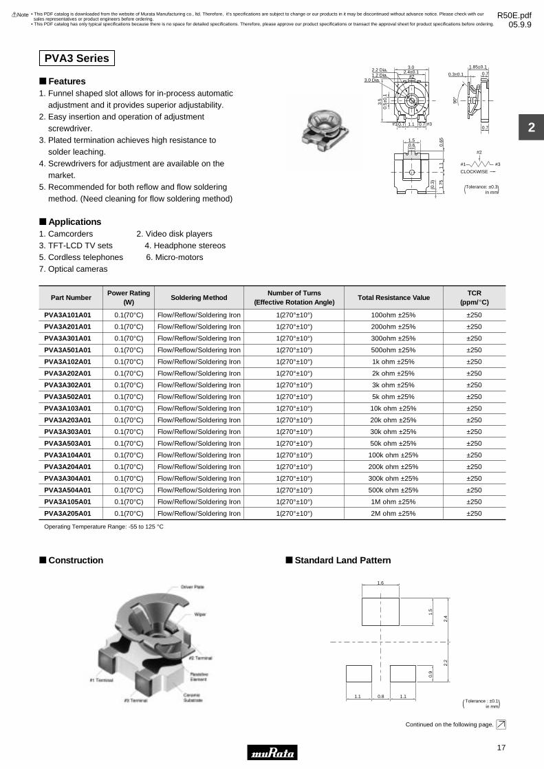
Construction Standard Land Pattern
1.6
1.5
2.4
2.2
0.9
1.1 0.8 1.1Tolerance : ±0.1 ( in mm)
Continued on the following page.
• This PDF catalog is downloaded from the website of Murata Manufacturing co., ltd. Therefore, it’s specifications are subject to change or our products in it may be discontinued without advance notice. Please check with our sales representatives or product engineers before ordering.
• This PDF catalog has only typical specifications because there is no space for detailed specifications. Therefore, please approve our product specifications or transact the approval sheet for product specifications before ordering.
!Note R50E.pdf05.9.9

18
2
!Note • Please read rating and !CAUTION (for storage, operating, rating, soldering, mounting and handling) in this catalog to prevent smoking and/or burning, etc.• This catalog has only typical specifications because there is no space for detailed specifications. Therefore, please approve our product specifications or transact the approval sheet for product specifications before ordering.
Continued from the preceding page.
CharacteristicsRes. Change : ±3%
Res. Change : ±3%
Res. Change : ±3%
Res. Change : ±3%
Res. Change : ±3%
±250ppm/˚C
Res. Change : ±10% (10 cycles)
Humidity Exposure
High Temperature
Exposure
Humidity Load Life
Load Life
Temperature Cycle
Temperature Coefficient
of Resistance
Rotational Life
• This PDF catalog is downloaded from the website of Murata Manufacturing co., ltd. Therefore, it’s specifications are subject to change or our products in it may be discontinued without advance notice. Please check with our sales representatives or product engineers before ordering.
• This PDF catalog has only typical specifications because there is no space for detailed specifications. Therefore, please approve our product specifications or transact the approval sheet for product specifications before ordering.
!Note R50E.pdf05.9.9

PVZ3/PVS3/PVA3 Series Notice
19
2
!Note • Please read rating and !CAUTION (for storage, operating, rating, soldering, mounting and handling) in this catalog to prevent smoking and/or burning, etc.• This catalog has only typical specifications because there is no space for detailed specifications. Therefore, please approve our product specifications or transact the approval sheet for product specifications before ordering.
Notice (Operating and Storage Conditions)1. Store in temperatures of -10 to +40 deg. C and relative humidity of 30-85%RH.2. Do not store in or near corrosive gases.3. Use within six months after delivery. 4. Open the package just before using.5. Do not store under direct sunlight.6. If you use the trimmer potentiometer in an environment other than listed below, please consult with a Murata factory representative prior to using. The trimmer potentiometer should not be used under the following environmental conditions:
(1) Corrosive gaseous atmosphere (Ex. Chlorine gas, Hydrogen sulfide gas, Ammonia gas, Sulfuric acid gas, Nitric oxide gas, etc.) (2) In liquid (Ex. Oil, Medical liquid, Organic solvent, etc.) (3) Dusty/dirty atmosphere (4) Direct sunlight (5) Static voltage nor electric/magnetic fields (6) Direct sea breeze (7) Other variations of the above
Notice (Rating)1. When using with partial load (rheostat), minimize the power depending on the resistance value.2. The maximum input voltage to a trimmer potentiometer should not exceed (P•R)^1/2 or the maximum operating voltage, whichever is smaller.3. If the trimmer potentiometer is used in DC and high humidity conditions, please connect wiper (#2) for plus and resistive element (#1 or #3) for minus. (PVZ Series only)
Notice (Soldering and Mounting)1. Soldering (1) Soldering condition Refer to the temperature profile. If the soldering conditions are not suitable, e.g., excessive time and/or excessive temperature, the trimmer potentiometer may deviate from the specified characteristics. (2) Flow soldering is available for PVA3 series. For PVZ3 and PVS3, do not use flow soldering method (dipping). If you use the flow soldering method, the trimmer potentiometer may not function. (3) Use our standard land dimension. Excessive land area causes displacement due to the effect of the surface tension of the solder. Insufficient land area leads to insufficient soldering strength of the chip. (4) Apply the appropriate amount of solder paste. The thickness of solder paste should be printed from 150 micro m to 200 micro m (PVZ3 series should be printed from 100 micro m to 150 micro m) and the dimension of land pattern used should be Murata's standard land pattern at reflow soldering. Insufficient amounts of solder can lead to insufficient soldering strength on PCB.
Excessive amounts of solder may cause bridging between the terminals. (5) The soldering iron should not come in contact with the case of the trimmer potentiometer. If such contact does occur, the trimmer potentiometer may be damaged. (PVZ Series only)2. Mounting (1) Do not apply excessive force (preferably 4.9N (Ref.; 500gf) max.), when the trimmer potentiometer is mounted to the PCB. (2) Do not warp and/or bend PC board to prevent trimmer potentiometer from breakage. (3) In chip placers, the recommended size of the cylindrical pick-up nozzle should be outer dimension 2.5-2.8mm dia. and inner dimension 2mm dia.3. Cleaning (1) In case there is flux on the resistive element, clean sufficiently with cleaning solvents and completely remove all residual flux. (2) Isopropyl-alcohol and Ethyl-alcohol are applicable solvents for cleaning. If you use any other types of solvents, please evaluate performance by your product.
• This PDF catalog is downloaded from the website of Murata Manufacturing co., ltd. Therefore, it’s specifications are subject to change or our products in it may be discontinued without advance notice. Please check with our sales representatives or product engineers before ordering.
• This PDF catalog has only typical specifications because there is no space for detailed specifications. Therefore, please approve our product specifications or transact the approval sheet for product specifications before ordering.
!Note R50E.pdf05.9.9

PVZ3/PVS3/PVA3 Series Notice
20
2
!Note • Please read rating and !CAUTION (for storage, operating, rating, soldering, mounting and handling) in this catalog to prevent smoking and/or burning, etc.• This catalog has only typical specifications because there is no space for detailed specifications. Therefore, please approve our product specifications or transact the approval sheet for product specifications before ordering.
Soldering Profile
Tem
pera
ture
(°C
)
t3
t2
T3T2
T5
T4
T1
Time (s)t1
1. Soldering profile for Lead-free solder (96.5Sn/3.0Ag/0.5Cu)
Soldering profile for Lead-free solder (96.5Sn/3.0Ag/0.5Cu), Eutectic solder (63Sn/37Pb)
Standard Profile
Pre-heating Heating Cycle ofReflow
Cycle ofReflow
Time°C
Series
PVA3
PVS3
PVZ3A***A01
PVZ3A***C01
PVZ3K***E01
PVZ3R***E01
Temp. (T1)
°C
Time (t1)
sec.
Temp. (T2)
°C
Time (t2)
sec.
Pre-heating Heating
Time°C
Temp. (T1)
°C
Time (t1)
sec.
Temp. (T4)
°C
Time (t3)
sec.
Limit Profile
2
2
1
2
2
2
245±3
245±3
240
245±3
245±3
245±3
150 to 180
150 to 180
130 to 160
150 to 180
150 to 180
150 to 180
60 to 120
60 to 120
60 to 120
60 to 120
60 to 120
60 to 120
220
220
200
220
220
220
30 to 60
30 to 60
20 to 50
30 to 60
30 to 60
30 to 60
2
2
2
2
2
2
260 +5/-0
260 +5/-0
240
260
260
260
150 to 180
150 to 180
130 to 160
150 to 180
150 to 180
150 to 180
60 to 120
60 to 120
60 to 120
60 to 120
60 to 120
60 to 120
230
220
200
220
220
220
30 to 50
30 to 60
20 to 50
30 to 60
30 to 60
30 to 60
Limit Profile
Standard Profile
Standard Profile
Pre-heating HeatingCycle of Flow
Time
Series
PVA3
Temp. (T1)
°C
Time (t1)
sec.
Temp. (T2)
°C
Time (t2)
sec.
Pre-heating HeatingCycle of Flow
Time
Temp. (T1)
°C
Time (t1)
sec.
Temp. (T3)
°C
Time (t2)
sec.
Limit Profile
1150 60 to 120 250 5 max. 2150 60 to 120 265±3 5 max.
Standard Profile
Pre-heating HeatingSeries
PVA3
PVS3
PVZ3A***A01
PVZ3A***C01
PVZ3K***E01
PVZ3R***E01
Temp. (T1)
°C
Time (t1)
sec.
Temp. (T2)
°C
Time (t2)
sec.
Tem
pera
ture
(°C
)
Time (s)
Standard Profile
t1
T1 t2
T3
T2
2. Soldering profile for Eutectic solder (63Sn/37Pb)
(Limit profile: refer to 1)
Standard Condition
Series
PVA3, PVS3, PVZ3A***A01, PVZ3A***C01, PVZ3K***E01, PVZ3R***E01
Temperatureof Soldering
Iron TipSoldering Time
Soldering IronPower Output
350±10 3 max. 30 max. 1
Cycle ofSoldering Iron
°C sec. W Time
Tem
pera
ture
(°C
)
t1
t2Heating
Pre-heating
T3T2
T1
Time (s)
Limit Profile
Standard Profile
Flow Soldering Profile
Reflow Soldering Profile
PeakTemperature
(T3)
PeakTemperature
(T5)
Cycle ofReflow
Time°C
1230150 60 to 120 183 30
PeakTemperature
(T3)
Soldering Iron
• This PDF catalog is downloaded from the website of Murata Manufacturing co., ltd. Therefore, it’s specifications are subject to change or our products in it may be discontinued without advance notice. Please check with our sales representatives or product engineers before ordering.
• This PDF catalog has only typical specifications because there is no space for detailed specifications. Therefore, please approve our product specifications or transact the approval sheet for product specifications before ordering.
!Note R50E.pdf05.9.9

PVZ3/PVS3/PVA3 Series Notice
21
2
!Note • Please read rating and !CAUTION (for storage, operating, rating, soldering, mounting and handling) in this catalog to prevent smoking and/or burning, etc.• This catalog has only typical specifications because there is no space for detailed specifications. Therefore, please approve our product specifications or transact the approval sheet for product specifications before ordering.
Notice (Handling)1. Use suitable screwdrivers that fit comfortably in driver slot. We recommend the screwdrivers below. * Recommended screwdriver for manual adjustment >VESSEL MFG.: NO.9000+1.7x30 (Murata P/N: KMDR080) >TORAY MFG.: SA-2225 (Murata P/N: KMDR070) * Recommended screwdriver for automatic adjustment >TORAY MFG.: JB-2225 (Murata P/N: KMBT070) 2. Don't apply more than 4.9N (Ref.; 500gf) of twist and stress after mounting onto PCB to prevent contact intermittence. If excessive force is applied, the trimmer potentiometer may not function.
3. Please use within the effective rotational angle. PVZ3/PVA3 Series do not have a mechanical stop for over rotation. In cases out of effective rotational angle, the trimmer potentiometer may not function.4. When using a lock paint to fix slot position or cover the rotor, please evaluate performance by your product. Lock paint may cause corrosion or electrical contact problems.
Notice (Other)1. Please make sure that your product has been evaluated and confirmed against your specifications when our product is mounted to your product.2. Murata cannot guarantee trimmer potentiometer integrity when used under conditions other than those specified in this document.
• This PDF catalog is downloaded from the website of Murata Manufacturing co., ltd. Therefore, it’s specifications are subject to change or our products in it may be discontinued without advance notice. Please check with our sales representatives or product engineers before ordering.
• This PDF catalog has only typical specifications because there is no space for detailed specifications. Therefore, please approve our product specifications or transact the approval sheet for product specifications before ordering.
!Note R50E.pdf05.9.9

22
3
!Note • Please read rating and !CAUTION (for storage, operating, rating, soldering, mounting and handling) in this catalog to prevent smoking and/or burning, etc.• This catalog has only typical specifications because there is no space for detailed specifications. Therefore, please approve our product specifications or transact the approval sheet for product specifications before ordering.
Trimmer PotentiometersSMD Sealed Type 2mm Size PVF2 Series
Features1. Ultra-compact size of "2x2x2.3mm" 2. A sealed structure prevents liquids (water, cleaning liquid, sweat, etc.) from entering.3. As for the resistance change characteristics, both a log curve type and linear type are available.4. A rotation service life of 100 cycles is guaranteed.5. Can be automatically mounted using a chip placer, as well as mounted using reflow soldering.
Applications1. Hearing aids2. Ultra-compact sensors or the like3. Applications requiring ultra-compactness, and a sealed structure
Marking 2.00#2
#1 #3
1.6dia.
2.00
0.30
2.15
max
.
2.30±0.15
0.70
±0.1
5
0.70
±0.1
5
0.30±0.15
0.500.30 0.50
0.30
0.50
#2 (Wiper contact)
#1 #3
Clockwise
CIRCUIT Tolerance : ±0.10 ( in mm )
Part NumberPower Rating
(W)Soldering Method
Number of Turns(Effective Rotation Angle)
Total Resistance ValueTCR
(ppm/°C)
PVF2A501A11 0.001(50°C) Reflow/Soldering Iron 1(210°±10°) 500ohm ±30% ±500
PVF2A102A11 0.001(50°C) Reflow/Soldering Iron 1(210°±10°) 1k ohm ±30% ±500
PVF2A202A11 0.001(50°C) Reflow/Soldering Iron 1(210°±10°) 2k ohm ±30% ±500
PVF2A502A11 0.001(50°C) Reflow/Soldering Iron 1(210°±10°) 5k ohm ±30% ±500
PVF2A103A11 0.001(50°C) Reflow/Soldering Iron 1(210°±10°) 10k ohm ±30% ±500
PVF2A203A11 0.001(50°C) Reflow/Soldering Iron 1(210°±10°) 20k ohm ±30% ±500
PVF2A503A11 0.001(50°C) Reflow/Soldering Iron 1(210°±10°) 50k ohm ±30% ±500
PVF2A104A11 0.001(50°C) Reflow/Soldering Iron 1(210°±10°) 100k ohm ±30% ±500
PVF2A204A11 0.001(50°C) Reflow/Soldering Iron 1(210°±10°) 200k ohm ±30% ±500
PVF2A504A11 0.001(50°C) Reflow/Soldering Iron 1(210°±10°) 500k ohm ±30% ±500
PVF2A105A11 0.001(50°C) Reflow/Soldering Iron 1(210°±10°) 1M ohm ±30% ±500
PVF2A102A41 0.001(50°C) Reflow/Soldering Iron 1(210°±10°) 1k ohm ±30% ±500
PVF2A202A41 0.001(50°C) Reflow/Soldering Iron 1(210°±10°) 2k ohm ±30% ±500
PVF2A502A41 0.001(50°C) Reflow/Soldering Iron 1(210°±10°) 5k ohm ±30% ±500
PVF2A103A41 0.001(50°C) Reflow/Soldering Iron 1(210°±10°) 10k ohm ±30% ±500
PVF2A203A41 0.001(50°C) Reflow/Soldering Iron 1(210°±10°) 20k ohm ±30% ±500
PVF2A503A41 0.001(50°C) Reflow/Soldering Iron 1(210°±10°) 50k ohm ±30% ±500
PVF2A104A41 0.001(50°C) Reflow/Soldering Iron 1(210°±10°) 100k ohm ±30% ±500
PVF2A204A41 0.001(50°C) Reflow/Soldering Iron 1(210°±10°) 200k ohm ±30% ±500
PVF2A504A41 0.001(50°C) Reflow/Soldering Iron 1(210°±10°) 500k ohm ±30% ±500
PVF2A102A51 0.001(50°C) Reflow/Soldering Iron 1(210°±10°) 1k ohm ±30% ±500
PVF2A202A51 0.001(50°C) Reflow/Soldering Iron 1(210°±10°) 2k ohm ±30% ±500
PVF2A502A51 0.001(50°C) Reflow/Soldering Iron 1(210°±10°) 5k ohm ±30% ±500
PVF2A103A51 0.001(50°C) Reflow/Soldering Iron 1(210°±10°) 10k ohm ±30% ±500
PVF2A203A51 0.001(50°C) Reflow/Soldering Iron 1(210°±10°) 20k ohm ±30% ±500
PVF2A503A51 0.001(50°C) Reflow/Soldering Iron 1(210°±10°) 50k ohm ±30% ±500
PVF2A104A51 0.001(50°C) Reflow/Soldering Iron 1(210°±10°) 100k ohm ±30% ±500
PVF2A204A51 0.001(50°C) Reflow/Soldering Iron 1(210°±10°) 200k ohm ±30% ±500
PVF2A504A51 0.001(50°C) Reflow/Soldering Iron 1(210°±10°) 500k ohm ±30% ±500
PVF2A102A81 0.001(50°C) Reflow/Soldering Iron 1(210°±10°) 1k ohm ±30% ±500
PVF2A202A81 0.001(50°C) Reflow/Soldering Iron 1(210°±10°) 2k ohm ±30% ±500
PVF2A502A81 0.001(50°C) Reflow/Soldering Iron 1(210°±10°) 5k ohm ±30% ±500
PVF2A103A81 0.001(50°C) Reflow/Soldering Iron 1(210°±10°) 10k ohm ±30% ±500
PVF2A203A81 0.001(50°C) Reflow/Soldering Iron 1(210°±10°) 20k ohm ±30% ±500
Continued on the following page.
• This PDF catalog is downloaded from the website of Murata Manufacturing co., ltd. Therefore, it’s specifications are subject to change or our products in it may be discontinued without advance notice. Please check with our sales representatives or product engineers before ordering.
• This PDF catalog has only typical specifications because there is no space for detailed specifications. Therefore, please approve our product specifications or transact the approval sheet for product specifications before ordering.
!Note R50E.pdf05.9.9

23
3
!Note • Please read rating and !CAUTION (for storage, operating, rating, soldering, mounting and handling) in this catalog to prevent smoking and/or burning, etc.• This catalog has only typical specifications because there is no space for detailed specifications. Therefore, please approve our product specifications or transact the approval sheet for product specifications before ordering.
Part NumberPower Rating
(W)Soldering Method
Number of Turns(Effective Rotation Angle)
Total Resistance ValueTCR
(ppm/°C)
Continued from the preceding page.
PVF2A503A81 0.001(50°C) Reflow/Soldering Iron 1(210°±10°) 50k ohm ±30% ±500
PVF2A104A81 0.001(50°C) Reflow/Soldering Iron 1(210°±10°) 100k ohm ±30% ±500
PVF2A204A81 0.001(50°C) Reflow/Soldering Iron 1(210°±10°) 200k ohm ±30% ±500
PVF2A504A81 0.001(50°C) Reflow/Soldering Iron 1(210°±10°) 500k ohm ±30% ±500
PVF2A102A91 0.001(50°C) Reflow/Soldering Iron 1(210°±10°) 1k ohm ±30% ±500
PVF2A202A91 0.001(50°C) Reflow/Soldering Iron 1(210°±10°) 2k ohm ±30% ±500
PVF2A502A91 0.001(50°C) Reflow/Soldering Iron 1(210°±10°) 5k ohm ±30% ±500
PVF2A103A91 0.001(50°C) Reflow/Soldering Iron 1(210°±10°) 10k ohm ±30% ±500
PVF2A203A91 0.001(50°C) Reflow/Soldering Iron 1(210°±10°) 20k ohm ±30% ±500
PVF2A503A91 0.001(50°C) Reflow/Soldering Iron 1(210°±10°) 50k ohm ±30% ±500
PVF2A104A91 0.001(50°C) Reflow/Soldering Iron 1(210°±10°) 100k ohm ±30% ±500
PVF2A204A91 0.001(50°C) Reflow/Soldering Iron 1(210°±10°) 200k ohm ±30% ±500
PVF2A504A91 0.001(50°C) Reflow/Soldering Iron 1(210°±10°) 500k ohm ±30% ±500
Operating Temperature Range: -25 to 60 °CThe last three digits express the individual specification codes for Resistant Curve. Please refer to Resistance Curve on the following page for characteristics.
Construction
O-ring
Rotor
Terminal
Shaft
Case
SubstrateWiper
Resistive Element
Standard Land Pattern
0.60
0.90
0.90
2.20
0.60 0.60
0.40
Tolerance : ±0.10 ( in mm )
Characteristics
Linear-log. curve (Measured from terminal 1 to 2)
100
90
80
70
60
50
40
30
20
10
00
#120 40 60 80 100
#3Percent clockwise rotation (%)
Per
cent
res
ista
nce
(%) A11
A81
A41
Linear-log. log. curve (Measured from terminal 2 to 3)
100
90
80
70
60
50
40
30
20
10
00
#120 40 60 80 100
#3Percent clockwise rotation (%)
Per
cent
res
ista
nce
(%) A11
A91
A51
∆TR ±5%
∆TR ±15, -2%
∆V.S.S. ±5%
∆V.S.S. ±5%
∆TR +2, -10%
∆TR ±3%
∆TR ±10%
Temperature Cycle
Humidity
Vibration
Shock (100G)
Temperature Load Life
Low Temperature Exposure
Rotational Life (100 cycles)∆TR: Total Resistance Change
∆V.S.S. : Voltage Setting Stability
Resistance Curve
• This PDF catalog is downloaded from the website of Murata Manufacturing co., ltd. Therefore, it’s specifications are subject to change or our products in it may be discontinued without advance notice. Please check with our sales representatives or product engineers before ordering.
• This PDF catalog has only typical specifications because there is no space for detailed specifications. Therefore, please approve our product specifications or transact the approval sheet for product specifications before ordering.
!Note R50E.pdf05.9.9

PVF2 Series Notice
24
3
!Note • Please read rating and !CAUTION (for storage, operating, rating, soldering, mounting and handling) in this catalog to prevent smoking and/or burning, etc.• This catalog has only typical specifications because there is no space for detailed specifications. Therefore, please approve our product specifications or transact the approval sheet for product specifications before ordering.
Notice (Operating and Storage Conditions)1. Store in temperatures of -10 to +40 deg. C and relative humidity of 30-85%RH.2. Do not store in or near corrosive gases.3. Use within six months after delivery. 4. Open the package just before using.5. Do not store under direct sunlight.6. If you use the trimmer potentiometer in an environment other than listed below, please consult with a Murata factory representative prior to using. The trimmer potentiometer should not be used under the following environmental conditions:
(1) Corrosive gaseous atmosphere (Ex. Chlorine gas, Hydrogen sulfide gas, Ammonia gas, Sulfuric acid gas, Nitric oxide gas, etc.) (2) In liquid (Ex. Oil, Medical liquid, Organic solvent, etc.) (3) Dusty/dirty atmosphere (4) Direct sunlight (5) Static voltage nor electric/magnetic fields (6) Direct sea breeze (7) Other variations of the above
Notice (Rating)1. When using with partial load (rheostat), minimize the power depending on the resistance value.2. The maximum input voltage to a trimmer potentiometer should not exceed (P•R)^1/2 or the maximum operating voltage, whichever is smaller.3. If the trimmer potentiometer is used in DC and high humidity conditions, please connect wiper (#2) for plus and resistive element (#1 or #3) for minus.
Notice (Soldering and Mounting)1. Soldering (1) Soldering condition Refer to the temperature profile. If the soldering conditions are not suitable, e.g., excessive time and/or excessive temperature, the trimmer potentiometer may deviate from the specified characteristics. (2) Use our standard land dimension. Excessive land area causes displacement due to the effect of the surface tension of the solder. Insufficient land area leads to insufficient soldering strength of the chip. (3) The soldering iron should not come in contact with the case of the trimmer potentiometer. If such contact does occur, the trimmer potentiometer may be damaged. (4) Cannot be soldered using the flow soldering method. If you use the flow soldering method, the trimmer potentiometer may not function.2. Mounting (1) Use our standard land dimension. Excessive land area causes displacement due to the effect of the surface tension of the solder. Insufficient land area leads to insufficient soldering strength of the chip.
(2) Do not apply excessive force (preferably 4.9N (Ref.; 500gf) max.), when the trimmer potentiometer is mounted to the PCB. (3) Do not warp and/or bend PC board to prevent trimmer potentiometer from breakage.3. Cleaning (1) Isopropyl-alcohol and Ethyl-alcohol are applicable solvents for cleaning. If you use any other types of solvents, please consult with a Murata factory representative prior to using. (2) The total cleaning time by cold dipping, vapor and ultrasonic washing (conditions as below) method should be less than 3 minutes. (3) For ultra-sonic cleaning, the available condition is as follows. >Power: 600W (67 liter) max. >Frequency: 28kHz >Temperature: Ambient temperature Due to the ultra-sonic cleaning equipment's peculiar self-resonance point and that the cleaning compatibility usually depends on the jig construction and/or the cleaning condition such as the depth of immersion, please check the cleaning equipment to determine the suitable conditions.If the trimmer potentiometer is cleaned by other conditions, the trimmer potentiometer may be damaged.
• This PDF catalog is downloaded from the website of Murata Manufacturing co., ltd. Therefore, it’s specifications are subject to change or our products in it may be discontinued without advance notice. Please check with our sales representatives or product engineers before ordering.
• This PDF catalog has only typical specifications because there is no space for detailed specifications. Therefore, please approve our product specifications or transact the approval sheet for product specifications before ordering.
!Note R50E.pdf05.9.9

PVF2 Series Notice
25
3
!Note • Please read rating and !CAUTION (for storage, operating, rating, soldering, mounting and handling) in this catalog to prevent smoking and/or burning, etc.• This catalog has only typical specifications because there is no space for detailed specifications. Therefore, please approve our product specifications or transact the approval sheet for product specifications before ordering.
Soldering Profile
Tem
pera
ture
(°C
)
t3
t2
T3T2
T5
T4
T1
Time (s)t1
1. Soldering profile for Lead-free solder (96.5Sn/3.0Ag/0.5Cu)
Standard Profile
Pre-heating Heating Cycleof Reflow
Time°C
Temp. (T1)
°C
Time (t1)
sec.
Temp. (T2)
°C
Time (t2)
sec.
1230150 to 180 60 to 120 200 30
Limit Profile
Standard Profile
Pre-heating Heating
Time°C
Temp. (T1)
°C
Time (t1)
sec.
Temp. (T4)
°C
Time (t3)
sec.
Limit Profile
1240150 to 180 60 to 120 200 40
Standard Profile
Pre-heating Heating
Time°C
Temp. (T1)
°C
Time (t1)
sec.
Temp. (T2)
°C
Time (t2)
sec.
1230150 60 to 120 183 30
Tem
pera
ture
(°C
)
Time (s)
Standard Profile
t1
T1 t2
T3
T2
2. Soldering profile for Eutectic solder (63Sn/37Pb)
(Limit profile: refer to 1)
Standard Condition
Temperature of Soldering Iron Tip
°C
Soldering Time
sec.
Soldering Iron Power Output
W
260 3 max. 30 max. 1
Cycle of Soldering Iron
Time
Reflow Soldering Profile
PeakTemperature
(T3)
PeakTemperature
(T3)
Cycleof Reflow
PeakTemperature
(T5)
Soldering Iron
Cycleof Reflow
Notice (Handling)1. Use suitable screwdrivers that fit comfortably in driver slot.2. Don't apply more than 4.9N (Ref.; 500gf) of twist and stress after mounting onto PCB to prevent contact intermittence. If excessive force is applied, the trimmer potentiometer may not function.3. The rotational torque at the position of the adjustment range should not exceed the stop strength.4. When using a lock paint to fix slot position, please use adhesive resin without chlorine or sulfur (Three-bond "1401 series").
Notice (Other)1. Please make sure that your product has been evaluated and confirmed against your specifications when our product is mounted to your product.2. Murata cannot guarantee trimmer potentiometer integrity when used under conditions other than those specified in this document.
• This PDF catalog is downloaded from the website of Murata Manufacturing co., ltd. Therefore, it’s specifications are subject to change or our products in it may be discontinued without advance notice. Please check with our sales representatives or product engineers before ordering.
• This PDF catalog has only typical specifications because there is no space for detailed specifications. Therefore, please approve our product specifications or transact the approval sheet for product specifications before ordering.
!Note R50E.pdf05.9.9

26
4
!Note • Please read rating and !CAUTION (for storage, operating, rating, soldering, mounting and handling) in this catalog to prevent smoking and/or burning, etc.• This catalog has only typical specifications because there is no space for detailed specifications. Therefore, please approve our product specifications or transact the approval sheet for product specifications before ordering.
Trimmer PotentiometersSMD Sealed Type 3mm Size PVG3 Series
Features1. Sealed construction protects the interior from dust and liquid, which achieves stable performance.2. Driver plate with cross-slot is suitable for automatic adjustment.3. Rotor with large diameter and deep groove improves driver insertion.4. J-hook, Gull wing terminal shape. Rear and through hole terminal shape. 5. 3mm and 4mm land pattern can be used without change. (Gull wing is suitable for 4mm size land pattern.)6. Heat resistance performance enables high temperature peak re-flow soldering.7. To be complied with RoHS directive by new Cd free cermet resistive material. Pb free terminals with Sn plating.
Applications1. Small sensors 2. Optical Transceiver Module3. Copier 4. Printer5. Compact Power Supply 6. Wireless Radio module
1.00±0.15
0.75±0.15
3.4
2.7
3.6
2.2
Dia
.
3.6
2.3
0.45
0.4 Depth
0.6#1
#2
#3
2.0
0.1 Min.
Tolerance : ±0.3 ( in mm )
#2
#1 #3CLOCKWISEPVG3A
1.00±0.15
0.75±0.15
3.4
2.7
4.5
2.2
Dia
.
3.6
2.3
0.45
0.4 Depth
2.0
#1
#2
#3
0.1 Min.
Tolerance : ±0.3 ( in mm )
#2
#1 #3CLOCKWISEPVG3G
3.6
2.8
2.8
5.6
3.4
2.2D
ia.
(2.5)
2.01.1
0.8±0.2 0.5
#2
#1#3
0.55 Depth0.5
0.5
0.5
0.1
min
.0.
1 m
in.
2.3
#2
#1 #3
CLOCKWISE
Tolerance : ±0.3 ( in mm )PVG3K
Part NumberPower Rating
(W)Soldering Method
Number of Turns(Effective Rotation Angle)
Total Resistance ValueTCR
(ppm/°C)
PVG3p100C01 0.25(70°C) Reflow/Soldering Iron 1(210°±10°) 10ohm ±20% ±150
PVG3p200C01 0.25(70°C) Reflow/Soldering Iron 1(210°±10) 20ohm ±20% ±150
PVG3p500C01 0.25(70°C) Reflow/Soldering Iron 1(210°±10°) 50ohm ±20% ±150
PVG3p101C01 0.25(70°C) Reflow/Soldering Iron 1(210°±10°) 100ohm ±20% ±150
PVG3p201C01 0.25(70°C) Reflow/Soldering Iron 1(210°±10°) 200ohm ±20% ±150
PVG3p501C01 0.25(70°C) Reflow/Soldering Iron 1(210°±10°) 500ohm ±20% ±150
PVG3p102C01 0.25(70°C) Reflow/Soldering Iron 1(210°±10°) 1k ohm ±20% ±150
PVG3p202C01 0.25(70°C) Reflow/Soldering Iron 1(210°±10°) 2k ohm ±20% ±150
PVG3p502C01 0.25(70°C) Reflow/Soldering Iron 1(210°±10°) 5k ohm ±20% ±150
PVG3p103C01 0.25(70°C) Reflow/Soldering Iron 1(210°±10°) 10k ohm ±20% ±150
PVG3p203C01 0.25(70°C) Reflow/Soldering Iron 1(210°±10°) 20k ohm ±20% ±150
PVG3p503C01 0.25(70°C) Reflow/Soldering Iron 1(210°±10°) 50k ohm ±20% ±150
Continued on the following page.
• This PDF catalog is downloaded from the website of Murata Manufacturing co., ltd. Therefore, it’s specifications are subject to change or our products in it may be discontinued without advance notice. Please check with our sales representatives or product engineers before ordering.
• This PDF catalog has only typical specifications because there is no space for detailed specifications. Therefore, please approve our product specifications or transact the approval sheet for product specifications before ordering.
!Note R50E.pdf05.9.9
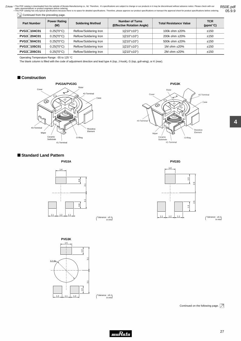
27
4
!Note • Please read rating and !CAUTION (for storage, operating, rating, soldering, mounting and handling) in this catalog to prevent smoking and/or burning, etc.• This catalog has only typical specifications because there is no space for detailed specifications. Therefore, please approve our product specifications or transact the approval sheet for product specifications before ordering.
Part NumberPower Rating
(W)Soldering Method
Number of Turns(Effective Rotation Angle)
Total Resistance ValueTCR
(ppm/°C)
Continued from the preceding page.
PVG3p104C01 0.25(70°C) Reflow/Soldering Iron 1(210°±10°) 100k ohm ±20% ±150
PVG3p204C01 0.25(70°C) Reflow/Soldering Iron 1(210°±10°) 200k ohm ±20% ±150
PVG3p504C01 0.25(70°C) Reflow/Soldering Iron 1(210°±10°) 500k ohm ±20% ±150
PVG3p105C01 0.25(70°C) Reflow/Soldering Iron 1(210°±10°) 1M ohm ±20% ±150
PVG3p205C01 0.25(70°C) Reflow/Soldering Iron 1(210°±10°) 2M ohm ±20% ±150
Operating Temperature Range: -55 to 125 °CThe blank column is filled with the code of adjustment direction and lead type A (top, J-hook), G (top, gull-wing), or K (rear).
ConstructionPVG3A/PVG3G
M
2CoverRotor
#2-Terminal
#1-Terminal
#3-Terminal
CeramicSubstrate
Wiper
Case
ResistiveElement
O-Ring
PVG3K
M
2Cover
Rotor
#2-Terminal
#1-Terminal
CeramicSubstrate
Wiper
Case
ResistiveElement
O-Ring
#3-Terminal
Standard Land PatternPVG3A
1.4
1.1 1.11.2
0.9
0.9
2.1
2.1
Tolerance : ±0.1 ( in mm)
PVG3G
1.4
1.1 1.11.2
1.3
2.5
2.5
1.3
Tolerance : ±0.1 ( in mm)
PVG3K
3.2 dia.
1.5
1.0
1.0
3.1
3.1
1.2 1.21.1 Tolerance : ±0.1 ( in mm)
Continued on the following page.
• This PDF catalog is downloaded from the website of Murata Manufacturing co., ltd. Therefore, it’s specifications are subject to change or our products in it may be discontinued without advance notice. Please check with our sales representatives or product engineers before ordering.
• This PDF catalog has only typical specifications because there is no space for detailed specifications. Therefore, please approve our product specifications or transact the approval sheet for product specifications before ordering.
!Note R50E.pdf05.9.9

28
4
!Note • Please read rating and !CAUTION (for storage, operating, rating, soldering, mounting and handling) in this catalog to prevent smoking and/or burning, etc.• This catalog has only typical specifications because there is no space for detailed specifications. Therefore, please approve our product specifications or transact the approval sheet for product specifications before ordering.
Continued from the preceding page.
Characteristics∆TR ±2%
∆V.S.S ±1%
∆TR ±2%
∆V.S.S ±1%
IR 10M ohm min.
∆TR ±1%
∆V.S.S ±1%
∆TR ±1%
∆V.S.S ±1%
∆TR ±3% or 3 ohm max., whichever is greater
∆V.S.S ±1%
∆TR ±2%
∆V.S.S ±2%
∆TR ±3%
∆V.S.S ±2%
∆TR RV100 kohm ... ±3% or 2 ohm max., whichever is greater
RG100 kohm ... +0/-10%
∆TR : Total Resistance Change
∆V.S.S : Voltage Setting Stability
IR : Insulation Resistance
R : Standard Total Resistance
Temperature Cycle
Humidity
Vibration (20G)
Shock (100G)
Temperature Load Life
Low Temperature Exposure
High Temperature Exposure
Rotational Life (50 cycles)
• This PDF catalog is downloaded from the website of Murata Manufacturing co., ltd. Therefore, it’s specifications are subject to change or our products in it may be discontinued without advance notice. Please check with our sales representatives or product engineers before ordering.
• This PDF catalog has only typical specifications because there is no space for detailed specifications. Therefore, please approve our product specifications or transact the approval sheet for product specifications before ordering.
!Note R50E.pdf05.9.9

PVG3 Series Notice
29
4
!Note • Please read rating and !CAUTION (for storage, operating, rating, soldering, mounting and handling) in this catalog to prevent smoking and/or burning, etc.• This catalog has only typical specifications because there is no space for detailed specifications. Therefore, please approve our product specifications or transact the approval sheet for product specifications before ordering.
Notice (Operating and Storage Conditions)1. Store in temperatures of -10 to +40 deg. C and relative humidity of 30-85%RH.2. Do not store in or near corrosive gases.3. Use within six months after delivery. 4. Open the package just before using.5. Do not store under direct sunlight.6. If you use the trimmer potentiometer in an environment other than listed below, please consult with a Murata factory representative prior to using. The trimmer potentiometer should not be used under the following environmental conditions:
(1) Corrosive gaseous atmosphere (Ex. Chlorine gas, Hydrogen sulfide gas, Ammonia gas, Sulfuric acid gas, Nitric oxide gas, etc.) (2) In liquid (Ex. Oil, Medical liquid, Organic solvent, etc.) (3) Dusty/dirty atmosphere (4) Direct sunlight (5) Static voltage nor electric/magnetic fields (6) Direct sea breeze (7) Other variations of the above
Notice (Rating)1. When using with partial load (rheostat), minimize the power depending on the resistance value.2. The maximum input voltage to a trimmer potentiometer should not exceed (P•R)^1/2 or the maximum operating voltage, whichever is smaller.3. The maximum input current to a trimmer potentiometer should not exceed (P/R)^1/2 or the allowable wiper current, whichever is smaller.
Notice (Soldering and Mounting)1. Soldering (1) Soldering condition Refer to the temperature profile. If the soldering conditions are not suitable, e.g., excessive time and/or excessive temperature, the trimmer potentiometer may deviate from the specified characteristics. (2) Cannot be soldered using the flow soldering method. If you use the flow soldering method, the trimmer potentiometer may not function. (3) The soldering iron should not come in contact with the case of the trimmer potentiometer. If such contact does occur, the trimmer potentiometer may be damaged. (4) Apply the appropriate amount of solder paste. If the amount of solder paste applied to the land is insufficient, the required adhesive strength cannot be obtained. If an excessive amount of solder paste is applied, solder bridging or flux overflow to the resistive element surface can occur.2. Mounting (1) Use our standard land dimension. Excessive land area causes displacement due to the effect of the surface tension of the solder. Insufficient land area leads to insufficient soldering strength of the chip. (2) Do not apply excessive force (preferably 4.9N (Ref.; 500gf) max.), when the trimmer potentiometer is mounted to the PCB.
(3) Do not warp and/or bend PC board to prevent trimmer potentiometer from breakage. (4) In chip placers, the size of the cylindrical pick-up nozzle should be outer dimension 2.5-3.0mm dia. and inner dimension 2.0-2.5mm dia.3. Cleaning (1) Isopropyl-alcohol and Ethyl-alcohol are applicable solvents for cleaning. If you use any other types of solvents, please consult with a Murata factory representative prior to using. (2) Less than 3 minutes of total cleaning time by dipping, vapor and ultra-sonic method. (3) In case of ultra-sonic cleaning method, cleaning conditions should be as follows. (a) Power: 600W (67lit.) max. (b) Frequency: 28kHz (c) Temperature: Ambient temperature Due to ultra-sonic cleaning equipment's peculiar self-resonance point and that cleaning compatibility usually depends on the jig construction and/or the cleaning condition such as the depth of immersion, please check the cleaning equipment to determine the suitable conditions. If the condition is not suitable, the trimmer potentiometer may deviate from specified characteristics.
• This PDF catalog is downloaded from the website of Murata Manufacturing co., ltd. Therefore, it’s specifications are subject to change or our products in it may be discontinued without advance notice. Please check with our sales representatives or product engineers before ordering.
• This PDF catalog has only typical specifications because there is no space for detailed specifications. Therefore, please approve our product specifications or transact the approval sheet for product specifications before ordering.
!Note R50E.pdf05.9.9

PVG3 Series Notice
30
4
!Note • Please read rating and !CAUTION (for storage, operating, rating, soldering, mounting and handling) in this catalog to prevent smoking and/or burning, etc.• This catalog has only typical specifications because there is no space for detailed specifications. Therefore, please approve our product specifications or transact the approval sheet for product specifications before ordering.
Soldering Profile
Tem
pera
ture
(°C
)
t3
t2
T3T2
T5
T4
T1
Time (s)t1
1. Soldering profile for Lead-free solder (96.5Sn/3.0Ag/0.5Cu)
Standard Profile
Pre-heating Heating Cycleof Reflow
Time°C
Temp. (T1)
°C
Time (t1)
sec.
Temp. (T2)
°C
Time (t2)
sec.
1245±3150 to 180 60 to 120 220 30 to 60
Limit Profile
Standard Profile
Pre-heating Heating
Time°C
Temp. (T1)
°C
Time (t1)
sec.
Temp. (T4)
°C
Time (t3)
sec.
Limit Profile
2260 +5/-0150 to 180 60 to 120 230 30 to 50
Standard Profile
Pre-heating Heating
Time°C
Temp. (T1)
°C
Time (t1)
sec.
Temp. (T2)
°C
Time (t2)
sec.
1230150 60 to 120 183 30
Tem
pera
ture
(°C
)
Time (s)
Standard Profile
t1
T1 t2
T3
T2
2. Soldering profile for Eutectic solder (63Sn/37Pb)
(Limit profile: refer to 1)
Standard Condition
Temperature of Soldering Iron Tip
°C
Soldering Time
sec.
Soldering Iron Power Output
W
350±10 3 max. 30 max. 1
Cycle of Soldering Iron
Time
Reflow Soldering Profile
PeakTemperature
(T3)
PeakTemperature
(T3)
Cycleof Reflow
PeakTemperature
(T5)
Soldering Iron
Cycleof Reflow
Notice (Handling)1. Use suitable screwdrivers that fit comfortably in driver slot. * Recommended screwdriver for manual adjustment TORAY INDUSTRIES, INC.: SA-2225 (Murata P/N: KMDR070) * Recommended screwdriver bit for automatic adjustment TORAY INDUSTRIES, INC.: JB-2225 (Mutata P/N: KMBT070) We can supply the screwdrivers above. If you place order, please specify the Murata P/N.2. Don't apply more than 9.8N (Ref.; 1kgf) of twist and stress after mounting onto PCB to prevent contact intermittence.
3. When adjusting with an adjustment tool, the applied force to the adjustment screw should not exceed 4.9N (Ref.; 500gf). If excessive force is applied, the trimmer potentiometer may not function due to damage.4. The rotational torque at the position of the adjustment range should not exceed the stop strength.5. When using a lock paint to fix slot position, please use adhesive resin without chlorine or sulfur (Three-bond "1401 series") and evaluate performance by your products. Lock paint may cause corrosion or electrical contact problems.
Notice (Other)1. Please make sure that your product has been evaluated and confirmed against your specifications when our product is mounted to your product.2. Murata cannot guarantee trimmer potentiometer integrity when used under conditions other than those specified in this document.
• This PDF catalog is downloaded from the website of Murata Manufacturing co., ltd. Therefore, it’s specifications are subject to change or our products in it may be discontinued without advance notice. Please check with our sales representatives or product engineers before ordering.
• This PDF catalog has only typical specifications because there is no space for detailed specifications. Therefore, please approve our product specifications or transact the approval sheet for product specifications before ordering.
!Note R50E.pdf05.9.9
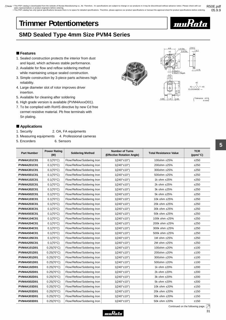
31
5
!Note • Please read rating and !CAUTION (for storage, operating, rating, soldering, mounting and handling) in this catalog to prevent smoking and/or burning, etc.• This catalog has only typical specifications because there is no space for detailed specifications. Therefore, please approve our product specifications or transact the approval sheet for product specifications before ordering.
Trimmer PotentiometersSMD Sealed Type 4mm Size PVM4 Series
Features1. Sealed construction protects the interior from dust and liquid, which achieves stable performance.2. Available for flow and reflow soldering method while maintaining unique sealed construction.3. Simple construction by 3-piece parts achieves high reliability.4. Large diameter slot of rotor improves driver insertion.5. Available for cleaning after soldering6. High grade version is available (PVM4AxxxD01).7. To be complied with RoHS directive by new Cd free cermet resistive material. Pb free terminals with Sn plating.
Applications1. Security 2. OA, FA equipments3. Measuring equipments 4. Professional cameras5. Encorders 6. Sensors
#2
#1 #3CLOCKWISE
#1
#2
#3
4.0
2.7±
0.1
(2.4
) 4.7
2.0±0.2
0.7
0.750.55±0.1
0.6
0.8
1.5
2.4
(0.3
)
0.85 1.8 0.85
0.35±0.1 Depth1.7
3.8 Dia.1.5 Dia.
Tolerance : ±0.3 ( in mm)
Part NumberPower Rating
(W)Soldering Method
Number of Turns(Effective Rotation Angle)
Total Resistance ValueTCR
(ppm/°C)
PVM4A101C01 0.1(70°C) Flow/Reflow/Soldering Iron 1(240°±10°) 100ohm ±25% ±250
PVM4A201C01 0.1(70°C) Flow/Reflow/Soldering Iron 1(240°±10°) 200ohm ±25% ±250
PVM4A301C01 0.1(70°C) Flow/Reflow/Soldering Iron 1(240°±10°) 300ohm ±25% ±250
PVM4A501C01 0.1(70°C) Flow/Reflow/Soldering Iron 1(240°±10°) 500ohm ±25% ±250
PVM4A102C01 0.1(70°C) Flow/Reflow/Soldering Iron 1(240°±10°) 1k ohm ±25% ±250
PVM4A202C01 0.1(70°C) Flow/Reflow/Soldering Iron 1(240°±10°) 2k ohm ±25% ±250
PVM4A302C01 0.1(70°C) Flow/Reflow/Soldering Iron 1(240°±10°) 3k ohm ±25% ±250
PVM4A502C01 0.1(70°C) Flow/Reflow/Soldering Iron 1(240°±10°) 5k ohm ±25% ±250
PVM4A103C01 0.1(70°C) Flow/Reflow/Soldering Iron 1(240°±10°) 10k ohm ±25% ±250
PVM4A203C01 0.1(70°C) Flow/Reflow/Soldering Iron 1(240°±10°) 20k ohm ±25% ±250
PVM4A303C01 0.1(70°C) Flow/Reflow/Soldering Iron 1(240°±10°) 30k ohm ±25% ±250
PVM4A503C01 0.1(70°C) Flow/Reflow/Soldering Iron 1(240°±10°) 50k ohm ±25% ±250
PVM4A104C01 0.1(70°C) Flow/Reflow/Soldering Iron 1(240°±10°) 100k ohm ±25% ±250
PVM4A204C01 0.1(70°C) Flow/Reflow/Soldering Iron 1(240°±10°) 200k ohm ±25% ±250
PVM4A304C01 0.1(70°C) Flow/Reflow/Soldering Iron 1(240°±10°) 300k ohm ±25% ±250
PVM4A504C01 0.1(70°C) Flow/Reflow/Soldering Iron 1(240°±10°) 500k ohm ±25% ±250
PVM4A105C01 0.1(70°C) Flow/Reflow/Soldering Iron 1(240°±10°) 1M ohm ±25% ±250
PVM4A205C01 0.1(70°C) Flow/Reflow/Soldering Iron 1(240°±10°) 2M ohm ±25% ±250
PVM4A101D01 0.25(70°C) Flow/Reflow/Soldering Iron 1(240°±10°) 100ohm ±20% ±100
PVM4A201D01 0.25(70°C) Flow/Reflow/Soldering Iron 1(240°±10°) 200ohm ±20% ±100
PVM4A301D01 0.25(70°C) Flow/Reflow/Soldering Iron 1(240°±10°) 300ohm ±20% ±100
PVM4A501D01 0.25(70°C) Flow/Reflow/Soldering Iron 1(240°±10°) 500ohm ±20% ±100
PVM4A102D01 0.25(70°C) Flow/Reflow/Soldering Iron 1(240°±10°) 1k ohm ±20% ±200
PVM4A202D01 0.25(70°C) Flow/Reflow/Soldering Iron 1(240°±10°) 2k ohm ±20% ±200
PVM4A302D01 0.25(70°C) Flow/Reflow/Soldering Iron 1(240°±10°) 3k ohm ±20% ±200
PVM4A502D01 0.25(70°C) Flow/Reflow/Soldering Iron 1(240°±10°) 5k ohm ±20% ±200
PVM4A103D01 0.25(70°C) Flow/Reflow/Soldering Iron 1(240°±10°) 10k ohm ±20% ±150
PVM4A203D01 0.25(70°C) Flow/Reflow/Soldering Iron 1(240°±10°) 20k ohm ±20% ±150
PVM4A303D01 0.25(70°C) Flow/Reflow/Soldering Iron 1(240°±10°) 30k ohm ±20% ±150
PVM4A503D01 0.25(70°C) Flow/Reflow/Soldering Iron 1(240°±10°) 50k ohm ±20% ±150
Continued on the following page.
• This PDF catalog is downloaded from the website of Murata Manufacturing co., ltd. Therefore, it’s specifications are subject to change or our products in it may be discontinued without advance notice. Please check with our sales representatives or product engineers before ordering.
• This PDF catalog has only typical specifications because there is no space for detailed specifications. Therefore, please approve our product specifications or transact the approval sheet for product specifications before ordering.
!Note R50E.pdf05.9.9

32
5
!Note • Please read rating and !CAUTION (for storage, operating, rating, soldering, mounting and handling) in this catalog to prevent smoking and/or burning, etc.• This catalog has only typical specifications because there is no space for detailed specifications. Therefore, please approve our product specifications or transact the approval sheet for product specifications before ordering.
Part NumberPower Rating
(W)Soldering Method
Number of Turns(Effective Rotation Angle)
Total Resistance ValueTCR
(ppm/°C)
Continued from the preceding page.
PVM4A104D01 0.25(70°C) Flow/Reflow/Soldering Iron 1(240°±10°) 100k ohm ±20% ±150
PVM4A204D01 0.25(70°C) Flow/Reflow/Soldering Iron 1(240°±10°) 200k ohm ±20% ±150
PVM4A304D01 0.25(70°C) Flow/Reflow/Soldering Iron 1(240°±10°) 300k ohm ±20% ±150
PVM4A504D01 0.25(70°C) Flow/Reflow/Soldering Iron 1(240°±10°) 500k ohm ±20% ±150
PVM4A105D01 0.25(70°C) Flow/Reflow/Soldering Iron 1(240°±10°) 1M ohm ±20% ±150
PVM4A205D01 0.25(70°C) Flow/Reflow/Soldering Iron 1(240°±10°) 2M ohm ±20% ±150
Operating Temperature Range: -55 to 125 °CThe last three digits express the individual specification codes. C01 for standard type and D01 for high-liability type.
Construction
Rotor
#1 Terminal
#3 Terminal
#2 Terminal
Wiper
ResistiveElement
CeramicSubstrate
Rubber
Standard Land Pattern
1.7
1.8
3.2
1.2
3.2
1.11.61.1 Tolerance : ±0.1 ( in mm)
CharacteristicsItem PVM4ApppC01 PVM4ApppD01
Res. Change : ±3%Humidity Exposure Res. Change : ±2%
Res. Change : ±3%High Temperature Exposure Res. Change : ±2%
Res. Change : ±3%Humidity Load Life Res. Change : ±3%
Res. Change : ±3%Temperature Load Life Res. Change : ±3%
Res. Change : ±3%Temperature Cycle Res. Change : ±2%
Res. Change : ±10% (20 cycles)Rotational Life Res. Change : ±5% (100 cycles)
• This PDF catalog is downloaded from the website of Murata Manufacturing co., ltd. Therefore, it’s specifications are subject to change or our products in it may be discontinued without advance notice. Please check with our sales representatives or product engineers before ordering.
• This PDF catalog has only typical specifications because there is no space for detailed specifications. Therefore, please approve our product specifications or transact the approval sheet for product specifications before ordering.
!Note R50E.pdf05.9.9

PVM4 Series Notice
33
5
!Note • Please read rating and !CAUTION (for storage, operating, rating, soldering, mounting and handling) in this catalog to prevent smoking and/or burning, etc.• This catalog has only typical specifications because there is no space for detailed specifications. Therefore, please approve our product specifications or transact the approval sheet for product specifications before ordering.
Notice (Operating and Storage Conditions)1. Store in temperatures of -10 to +40 deg. C and relative humidity of 30-85%RH.2. Do not store in or near corrosive gases.3. Use within six months after delivery. 4. Open the package just before using.5. Do not store under direct sunlight.6. If you use the trimmer potentiometer in an environment other than listed below, please consult with a Murata factory representative prior to using. The trimmer potentiometer should not be used under the following environmental conditions:
(1) Corrosive gaseous atmosphere (Ex. Chlorine gas, Hydrogen sulfide gas, Ammonia gas, Sulfuric acid gas, Nitric oxide gas, etc.) (2) In liquid (Ex. Oil, Medical liquid, Organic solvent, etc.) (3) Dusty/dirty atmosphere (4) Direct sunlight (5) Static voltage nor electric/magnetic fields (6) Direct sea breeze (7) Other variations of the above
Notice (Rating)1. When using with partial load (rheostat), minimize the power depending on the resistance value.2. The maximum input voltage to a trimmer potentiometer should not exceed (P•R)^1/2 or the maximum operating voltage, whichever is smaller.
3. The maximum input current to a trimmer potentiometer should not exceed (P/R)^1/2 or the allowable wiper current, whichever is smaller.
Notice (Soldering and Mounting)1. Soldering (1) Can be soldered by reflow soldering method, flow soldering method, and soldering iron. (In case of flow soldering, it is necessary to clean after soldering.) (2) Use our standard land dimension. Excessive land area causes displacement due to the effect of the surface tension of the solder. Insufficient land area leads to insufficient soldering strength of the chip. (3) Soldering condition Refer to the temperature profile. If the soldering conditions are not suitable, e.g., excessive time and/or excessive temperature, the trimmer potentiometer may deviate from the specified characteristics. (4) Apply the appropriate amount of solder paste. The thickness of solder paste should be printed from 100 micro m to 150 micro m and the dimension of land pattern used should be Murata's standard land pattern at reflow soldering. Insufficient amounts of solder can lead to insufficient soldering strength on PCB. Excessive amounts of solder may cause bridging between the terminals. (5) The soldering iron should not come in contact with the case of the trimmer potentiometer. If such contact does occur, the trimmer potentiometer may be damaged.2. Mounting (1) Do not apply excessive force (preferably 9.8N (Ref.; 1kgf) max.), when the trimmer potentiometer is mounted to the PCB. (2) Do not warp and/or bend PC board to prevent trimmer potentiometer from breakage.
(3) In chip placers, the recommended size of the cylindrical pick-up nozzle should be outer dimension 4.0mm dia. and inner dimension 2.0mm dia.3. Cleaning (1) Isopropyl alcohol and Ethyl alcohol are available materials for cleaning. For other materials, please consult with a Murata factory representative prior to using. (2) The following are the recommended cleaning conditions for the potentiometer. If this part is cleaned under any other conditions than these listed below, the sealing construction may be damaged. (Condition) Type1: Cold dipping/max. 5 min. Type2: Hot dipping/max. 2 min. Type3: Ultra-sonic washing/max. 1 min. (20W/litre or below) Type4: Hot dipping/max. 1 min.+ Ultra-sonic washing/max.1 min. (20W/litre or below) Type5: Hot dipping/max. 1 min.+ Ultra-sonic washing/max. 30 sec.+ (20W/litre or below)/ (Preferably max. 30 sec.) Vapor/max.30 sec. Due to ultra-sonic cleaning equipment's peculiar self-resonance point and that cleaning compatibility usually depends on the jig construction and/or the cleaning condition such as the depth of immersion, please check the cleaning equipment to determine the suitable conditions. If the condition is not suitable, the trimmer potentiometer may deviate from specified characteristics.
• This PDF catalog is downloaded from the website of Murata Manufacturing co., ltd. Therefore, it’s specifications are subject to change or our products in it may be discontinued without advance notice. Please check with our sales representatives or product engineers before ordering.
• This PDF catalog has only typical specifications because there is no space for detailed specifications. Therefore, please approve our product specifications or transact the approval sheet for product specifications before ordering.
!Note R50E.pdf05.9.9

PVM4 Series Notice
34
5
!Note • Please read rating and !CAUTION (for storage, operating, rating, soldering, mounting and handling) in this catalog to prevent smoking and/or burning, etc.• This catalog has only typical specifications because there is no space for detailed specifications. Therefore, please approve our product specifications or transact the approval sheet for product specifications before ordering.
Soldering Profile
Tem
pera
ture
(°C
)
t3
t2
T3T2
T5
T4
T1
Time (s)t1
1. Soldering profile for Lead-free solder (96.5Sn/3.0Ag/0.5Cu)
Standard Profile
Pre-heating Heating Cycleof Reflow
Time°C
Temp. (T1)
°C
Time (t1)
sec.
Temp. (T2)
°C
Time (t2)
sec.
2245±3150 to 180 60 to 120 220 30 to 60
Limit Profile
Standard Profile
Pre-heating Heating
Time°C
Temp. (T1)
°C
Time (t1)
sec.
Temp. (T4)
°C
Time (t3)
sec.
Limit Profile
2260 +5/-0150 to 180 60 to 120 230 30 to 50
Standard Profile
Pre-heating Heating
Time°C
Temp. (T1)
°C
Time (t1)
sec.
Temp. (T2)
°C
Time (t2)
sec.
1230150 60 to 120 183 30
Tem
pera
ture
(°C
)
Time (s)
Standard Profile
t1
T1 t2
T3
T2
2. Soldering profile for Eutectic solder (63Sn/37Pb)
(Limit profile: refer to 1)
Standard Condition
Temperature of Soldering Iron Tip
°C
Soldering Time
sec.
Soldering Iron Power Output
W
350±10 3 max. 30 max. 1
Cycle of Soldering Iron
Time
Reflow Soldering Profile
Flow Soldering Profile
PeakTemperature
(T3)
PeakTemperature
(T3)
Cycleof Reflow
PeakTemperature
(T5)
Soldering Iron
Cycleof Reflow
Soldering profile for Lead-free solder (96.5Sn/3.0Ag/0.5Cu), Eutectic solder (63Sn/37Pb)
Standard Profile
Pre-heating Heating
Temp. (T1)
°C
Time (t1)
sec.
Temp. (T2)
°C
Time (t2)
sec.
150 60 to 120 250 5 max. 1Tem
pera
ture
(°C
)
t1
t2
T3T2
T1
Time (s)
Limit Profile
Standard Profile
Cycle of Flow
Time
Limit Profile
Pre-heating Heating
Temp. (T1)
°C
Time (t1)
sec.
Temp. (T3)
°C
Time (t2)
sec.
150 60 to 120 265±3 5 max. 2
Cycle of Flow
Time
Heating
Pre-heating
• This PDF catalog is downloaded from the website of Murata Manufacturing co., ltd. Therefore, it’s specifications are subject to change or our products in it may be discontinued without advance notice. Please check with our sales representatives or product engineers before ordering.
• This PDF catalog has only typical specifications because there is no space for detailed specifications. Therefore, please approve our product specifications or transact the approval sheet for product specifications before ordering.
!Note R50E.pdf05.9.9

PVM4 Series Notice
35
5
!Note • Please read rating and !CAUTION (for storage, operating, rating, soldering, mounting and handling) in this catalog to prevent smoking and/or burning, etc.• This catalog has only typical specifications because there is no space for detailed specifications. Therefore, please approve our product specifications or transact the approval sheet for product specifications before ordering.
Notice (Handling)1. Use suitable screwdrivers that fit comfortably in driver slot. We recommend the screwdriver below. * Recommended screwdriver for manual adjustment VESSEL MFG.: NO. 9000-2.6x30 (Murata P/N: KMDR120) We can supply the screwdrivers above. If you place order, please specify the Murata P/N.2. Don't apply more than 4.9N (Ref.; 500gf) of twist and stress after mounting onto PCB to prevent contact intermittence. If excessive force is applied, the trimmer potentiometer may not function.
3. Please use within the effective rotational angle. The potentiometer does not have a mechanical stop for over rotation. In cases out of effective rotational angle, the trimmer potentiometer may not function.4. When using a lock paint to fix slot position, please use adhesive resin without chlorine or sulfur (Three-bond "1401 series") and evaluate performance by your products. Lock paint may cause corrosion or electrical contact problems.
Notice (Other)1. Please make sure that your product has been evaluated and confirmed against your specifications when our product is mounted to your product.2. Murata cannot guarantee trimmer potentiometer integrity when used under conditions other than those specified in this document.
• This PDF catalog is downloaded from the website of Murata Manufacturing co., ltd. Therefore, it’s specifications are subject to change or our products in it may be discontinued without advance notice. Please check with our sales representatives or product engineers before ordering.
• This PDF catalog has only typical specifications because there is no space for detailed specifications. Therefore, please approve our product specifications or transact the approval sheet for product specifications before ordering.
!Note R50E.pdf05.9.9

36
6
!Note • Please read rating and !CAUTION (for storage, operating, rating, soldering, mounting and handling) in this catalog to prevent smoking and/or burning, etc.• This catalog has only typical specifications because there is no space for detailed specifications. Therefore, please approve our product specifications or transact the approval sheet for product specifications before ordering.
Trimmer PotentiometersSMD Sealed Type Multi-turns PVG5/PV01 Series
PVG5 Series
Features1. Sealed construction protects the interior from dust and liquid, which achieves stable performance.2. Available with reflow soldering method3. Available for ultrasonic cleaning after soldering4. Clutch mechanism prevents excessive wiper rotation.5. Both Top and side adjustment directions6. Ultra smaller volume (1/5-1/2) than leaded multi-turn potentiometer. 7. To be complied with RoHS directive by new Cd free cermet resistive material. Pb free terminals with Sn plating.
Applications1. Measuring instruments 2. OA equipment3. Madical equipment 4. Power supply5. Sensors 6. Base station for cellular phone
4.8
5.0
3.5
3.9
3-0.8
0.2
2.41.2
2.6 3-
0.9
3-0.7
0.5
2.5
ADJ. SlotDIA 1.5Width 0.6Depth 0.5
#2
#3 #1
#2
#1 #3
CLOCKWISE
Schematic
Tolerance : ±0.3 ( in mm)
PVG5A
1.2
2.4
2.3
4.9
3.7
3-0.7
2.6
4.8
3-0.
8
3-0.9
0.5
#2
#1 #3
CLOCKWISE
#1
#2#3
Schematic
ADJ.SlotDIA 1.5Width 0.6Depth 0.5
Tolerance : ±0.3 ( in mm)
PVG5H
Part NumberPower Rating
(W)Soldering Method
Number of Turns(Effective Rotation Angle)
Total Resistance ValueTCR
(ppm/°C)
PVG5p100C01 0.25(70°C) Reflow/Soldering Iron 11 10ohm ±10% ±150
PVG5p200C01 0.25(70°C) Reflow/Soldering Iron 11 20ohm ±10% ±150
PVG5p500C01 0.25(70°C) Reflow/Soldering Iron 11 50ohm ±10% ±150
PVG5p101C01 0.25(70°C) Reflow/Soldering Iron 11 100ohm ±10% ±150
PVG5p201C01 0.25(70°C) Reflow/Soldering Iron 11 200ohm ±10% ±150
PVG5p501C01 0.25(70°C) Reflow/Soldering Iron 11 500ohm ±10% ±150
PVG5p102C01 0.25(70°C) Reflow/Soldering Iron 11 1k ohm ±10% ±150
PVG5p202C01 0.25(70°C) Reflow/Soldering Iron 11 2k ohm ±10% ±150
PVG5p502C01 0.25(70°C) Reflow/Soldering Iron 11 5k ohm ±10% ±150
PVG5p103C01 0.25(70°C) Reflow/Soldering Iron 11 10k ohm ±10% ±150
PVG5p203C01 0.25(70°C) Reflow/Soldering Iron 11 20k ohm ±10% ±150
PVG5p503C01 0.25(70°C) Reflow/Soldering Iron 11 50k ohm ±10% ±150
PVG5p104C01 0.25(70°C) Reflow/Soldering Iron 11 100k ohm ±10% ±150
PVG5p204C01 0.25(70°C) Reflow/Soldering Iron 11 200k ohm ±10% ±150
PVG5p504C01 0.25(70°C) Reflow/Soldering Iron 11 500k ohm ±10% ±150
PVG5p105C01 0.25(70°C) Reflow/Soldering Iron 11 1M ohm ±10% ±150
PVG5p205C01 0.25(70°C) Reflow/Soldering Iron 11 2M ohm ±10% ±150
Operating Temperature Range: -55 to 125 °CThe blank column is filled with the code of adjustment direction A (top) or H (side).
• This PDF catalog is downloaded from the website of Murata Manufacturing co., ltd. Therefore, it’s specifications are subject to change or our products in it may be discontinued without advance notice. Please check with our sales representatives or product engineers before ordering.
• This PDF catalog has only typical specifications because there is no space for detailed specifications. Therefore, please approve our product specifications or transact the approval sheet for product specifications before ordering.
!Note R50E.pdf05.9.9

37
6
!Note • Please read rating and !CAUTION (for storage, operating, rating, soldering, mounting and handling) in this catalog to prevent smoking and/or burning, etc.• This catalog has only typical specifications because there is no space for detailed specifications. Therefore, please approve our product specifications or transact the approval sheet for product specifications before ordering.
Construction
#2 Terminal
CaseGear
Adjustment Screw
Resistive ElementWiper
Ceramic Substrate#1, #3 Terminal
Standard Land PatternPVG5A
1.3
2.25
2.25
1.31.21.3
1.6
1.6
Tolerance : ±0.1 ( in mm)
PVG5H
2.8
2.8
1.31.01.3
1.6
1.6
1.3
Tolerance : ±0.1 ( in mm)
Characteristics∆TR ±2%
∆V.S.S. ±1%
∆TR ±2%
IR 10M ohm min.
∆TR ±1%
∆V.S.S. ±1%
∆TR ±1%
∆V.S.S. ±1%
∆TR ±3% or 3 ohm max.,
whichever is greater
∆V.S.S. ±1%
∆TR ±1%
∆V.S.S. ±1%
∆TR ±2%
∆V.S.S. ±1%
∆TR ±3% or 3 ohm max.,
whichever is greater
Temperature Cycle
Humidity
Vibration (20G)
Shock (100G)
Temperature Load Life
Low Temperature Exposure
High Temperature Exposure
Rotational Life (100 cycles)
∆TR : Total Resistance Change
∆V.S.S. : Voltage Setting Stability
IR : Insulation Resistance
• This PDF catalog is downloaded from the website of Murata Manufacturing co., ltd. Therefore, it’s specifications are subject to change or our products in it may be discontinued without advance notice. Please check with our sales representatives or product engineers before ordering.
• This PDF catalog has only typical specifications because there is no space for detailed specifications. Therefore, please approve our product specifications or transact the approval sheet for product specifications before ordering.
!Note R50E.pdf05.9.9

38
6
!Note • Please read rating and !CAUTION (for storage, operating, rating, soldering, mounting and handling) in this catalog to prevent smoking and/or burning, etc.• This catalog has only typical specifications because there is no space for detailed specifications. Therefore, please approve our product specifications or transact the approval sheet for product specifications before ordering.
PV01 Series
Features1. Small size (6.35x6.35x4.3mm)2. Sealed construction protects the interior from dust and liquid, which achieves stable performance.3. Available with reflow soldering method4. Available for ultrasonic cleaning after soldering5. Clutch mechanism prevents excessive wiper rotation.6. To be complied with RoHS directive by new Cd free cermet resistive material. Pb free terminals with Sn plating.
Applications1. Measuring instruments 2. FAX3. PPCs 4. Printers 5. Sensors
0.6±0.2
1.2
6.4
#2
#3#1
Clockwise
#2
1.1
4.0
6.7
1.8±0.2 DIA
1.0
0.6
3−1.
0
#1 #3
2.5 2.5
3−0.4±0.1 Dia.
Tolerance : ±0.3 ( in mm)
PV01P
0.6±0.2
1.2
6.4
#2
#3#1
Clockwise
#2
#1 #3
1.1
4.0
2.5 2.5
3−0.4±0.1 Dia.
6.7
1.8±0.2 Dia.
1.0
0.6
3−1.0
Tolerance : ±0.3 ( in mm)
PV01W
6.4
#2
#3#1
Clockwise
#2
#1 #3
4.0
2.5 2.5
3−0.4±0.1 Dia.
6.7
1.00.6
3−1.0
1.1
1.1
0.6±
0.2
1.8±
0.2
Dia
.
Tolerance : ±0.3 ( in mm)
PV01X
Part NumberPower Rating
(W)Soldering Method
Number of Turns(Effective Rotation Angle)
Total Resistance ValueTCR
(ppm/°C)
PV01p100C01 0.25(85°C) Reflow/Soldering Iron 12 10ohm ±10% ±150
PV01p200C01 0.25(85°C) Reflow/Soldering Iron 12 20ohm ±10% ±150
PV01p500C01 0.25(85°C) Reflow/Soldering Iron 12 50ohm ±10% ±150
PV01p101C01 0.25(85°C) Reflow/Soldering Iron 12 100ohm ±10% ±150
PV01p201C01 0.25(85°C) Reflow/Soldering Iron 12 200ohm ±10% ±150
PV01p501C01 0.25(85°C) Reflow/Soldering Iron 12 500ohm ±10% ±150
PV01p102C01 0.25(85°C) Reflow/Soldering Iron 12 1k ohm ±10% ±150
PV01p202C01 0.25(85°C) Reflow/Soldering Iron 12 2k ohm ±10% ±150
PV01p502C01 0.25(85°C) Reflow/Soldering Iron 12 5k ohm ±10% ±150
PV01p103C01 0.25(85°C) Reflow/Soldering Iron 12 10k ohm ±10% ±150
PV01p203C01 0.25(85°C) Reflow/Soldering Iron 12 20k ohm ±10% ±150
PV01p253C01 0.25(85°C) Reflow/Soldering Iron 12 25k ohm ±10% ±150
PV01p503C01 0.25(85°C) Reflow/Soldering Iron 12 50k ohm ±10% ±150
PV01p104C01 0.25(85°C) Reflow/Soldering Iron 12 100k ohm ±10% ±150
PV01p204C01 0.25(85°C) Reflow/Soldering Iron 12 200k ohm ±10% ±150
PV01p254C01 0.25(85°C) Reflow/Soldering Iron 12 250k ohm ±10% ±150
Continued on the following page.
• This PDF catalog is downloaded from the website of Murata Manufacturing co., ltd. Therefore, it’s specifications are subject to change or our products in it may be discontinued without advance notice. Please check with our sales representatives or product engineers before ordering.
• This PDF catalog has only typical specifications because there is no space for detailed specifications. Therefore, please approve our product specifications or transact the approval sheet for product specifications before ordering.
!Note R50E.pdf05.9.9

39
6
!Note • Please read rating and !CAUTION (for storage, operating, rating, soldering, mounting and handling) in this catalog to prevent smoking and/or burning, etc.• This catalog has only typical specifications because there is no space for detailed specifications. Therefore, please approve our product specifications or transact the approval sheet for product specifications before ordering.
Part NumberPower Rating
(W)Soldering Method
Number of Turns(Effective Rotation Angle)
Total Resistance ValueTCR
(ppm/°C)
Continued from the preceding page.
PV01p504C01 0.25(85°C) Reflow/Soldering Iron 12 500k ohm ±10% ±150
PV01p105C01 0.25(85°C) Reflow/Soldering Iron 12 1M ohm ±10% ±150
Operating Temperature Range: -55 to 125 °CThe blank column is filled with the code of adjustment direction P (side), W (top) or X (side).
Magazine packaging is standard for PV01 series.
ConstructionGear Case
Terminal
Adjustment Screw
Alumina Substrate
Wiper
Cermet ResistiveElement
Standard Land PatternPV01P
Tolerance : ±0.1 ( in mm)
1.6
1.6 1.6
1.8
1.8
3.4
4.85
4.85
PV01W/PV01X
1.6
1.6 1.6
1.8
1.8
3.4
3.8
3.8
Tolerance : ±0.1 ( in mm)
Characteristics∆TR ±1%
∆V.S.S. ±1%
∆TR ±2%
IR 100M ohm min.
∆TR ±1%
∆V.S.S. ±1%
∆TR ±1%
∆V.S.S. ±1%
∆TR ±2%
∆V.S.S. ±1%
∆TR ±1%
∆V.S.S. ±1%
∆TR ±2%
∆V.S.S. ±1%
∆TR RV100 ohm ... ±3%
RG100 ohm ... ±2%
Temperature Cycle
Humidity
Vibration (20G)
Shock (100G)
Temperature Load Life
Low Temperature Exposure
High Temperature Exposure
Rotational Life (200 cycles)
∆TR : Total Resistance Change
∆V.S.S. : Voltage Setting Stability
IR : Insulation Resistance
R : Standard Total Resistance
• This PDF catalog is downloaded from the website of Murata Manufacturing co., ltd. Therefore, it’s specifications are subject to change or our products in it may be discontinued without advance notice. Please check with our sales representatives or product engineers before ordering.
• This PDF catalog has only typical specifications because there is no space for detailed specifications. Therefore, please approve our product specifications or transact the approval sheet for product specifications before ordering.
!Note R50E.pdf05.9.9

PVG5/PV01 Series Notice
40
6
!Note • Please read rating and !CAUTION (for storage, operating, rating, soldering, mounting and handling) in this catalog to prevent smoking and/or burning, etc.• This catalog has only typical specifications because there is no space for detailed specifications. Therefore, please approve our product specifications or transact the approval sheet for product specifications before ordering.
Notice (Operating and Storage Conditions)1. Store in temperatures of -10 to +40 deg. C and relative humidity of 30-85%RH.2. Do not store in or near corrosive gases.3. Use within six months after delivery. 4. Open the package just before using.5. Do not store under direct sunlight.6. If you use the trimmer potentiometer in an environment other than listed below, please consult with a Murata factory representative prior to using. The trimmer potentiometer should not be used under the following environmental conditions:
(1) Corrosive gaseous atmosphere (Ex. Chlorine gas, Hydrogen sulfide gas, Ammonia gas, Sulfuric acid gas, Nitric oxide gas, etc.) (2) In liquid (Ex. Oil, Medical liquid, Organic solvent, etc.) (3) Dusty/dirty atmosphere (4) Direct sunlight (5) Static voltage nor electric/magnetic fields (6) Direct sea breeze (7) Other variations of the above
Notice (Rating)1. When using with partial load (rheostat), minimize the power depending on the resistance value.2. The maximum input voltage to a trimmer potentiometer should not exceed (P•R)^1/2 or the maximum operating voltage, whichever is smaller.3. The maximum input current to a trimmer potentiometer should not exceed (P/R)^1/2 or the allowable wiper current, whichever is smaller.
Notice (Soldering and Mounting)1. Soldering (1) Soldering condition Refer to the temperature profile. If the soldering conditions are not suitable, e.g., excessive time and/or excessive temperature, the trimmer capacitor may deviate from the specified characteristics. (2) Cannot be soldered using the flow soldering method. If you use the flow soldering method, the trimmer potentiometer may not function. (3) The soldering iron should not come in contact with the case of the trimmer potentiometer. If such contact does occur, the trimmer potentiometer may be damaged. (4) Insufficient amounts of solder can lead to insufficient soldering strength on PCB. Excessive amounts of solder may cause bridging between the terminals.2. Mounting (1) Use our standard land dimension. Excessive land area causes displacement due to the effect of the surface tension of the solder. Insufficient land area leads to insufficient soldering strength of the chip. (2) Do not apply excessive force (preferably 9.8N (Ref.; 1kgf) max.), when the trimmer potentiometer is mounted to the PCB. (3) Do not warp and/or bend PC board to prevent trimmer potentiometer from breakage.
(4) In chip placers, the recommended size of the cylindrical pick-up nozzle should be outer dimension 4.0mm dia. and inner dimension 2.0mm dia.3. Cleaning (1) Isopropyl-alcohol and Ethyl-alcohol are applicable solvents for cleaning. If you use any other types of solvents, please consult with a Murata factory representative prior to using. (2) The total cleaning time by cold dipping, vapor and ultrasonic washing (conditions as below) method should be less than 3 minutes. (3) For ultra-sonic cleaning, the available condition is as follows. >Power: 600W (67 liter) max. >Frequency: 28kHz >Temperature: Ambient temperature Due to the ultra-sonic cleaning equipment's peculiar self-resonance point and that the cleaning compatibility usually depends on the jig construction and/or the cleaning condition such as the depth of immersion, please check the cleaning equipment to determine the suitable conditions.If the trimmer potentiometer is cleaned by other conditions, the trimmer potentiometer may be damaged.
• This PDF catalog is downloaded from the website of Murata Manufacturing co., ltd. Therefore, it’s specifications are subject to change or our products in it may be discontinued without advance notice. Please check with our sales representatives or product engineers before ordering.
• This PDF catalog has only typical specifications because there is no space for detailed specifications. Therefore, please approve our product specifications or transact the approval sheet for product specifications before ordering.
!Note R50E.pdf05.9.9

PVG5/PV01 Series Notice
41
6
!Note • Please read rating and !CAUTION (for storage, operating, rating, soldering, mounting and handling) in this catalog to prevent smoking and/or burning, etc.• This catalog has only typical specifications because there is no space for detailed specifications. Therefore, please approve our product specifications or transact the approval sheet for product specifications before ordering.
Soldering ProfileT
empe
ratu
re (
°C)
t3
t2
T3T2
T5
T4
T1
Time (s)t1
1. Soldering profile for Lead-free solder (96.5Sn/3.0Ag/0.5Cu)
Standard Profile
Pre-heating Heating
Time°C
Series
PVG5
PV01
Temp. (T1)
°C
Time (t1)
sec.
Temp. (T2)
°C
Time (t2)
sec.
Pre-heating Heating
Time°C
Temp. (T1)
°C
Time (t1)
sec.
Temp. (T4)
°C
Time (t3)
sec.
Limit Profile
2
2
245±3
245±3
150 to 180
150 to 180
60 to 120
60 to 120
220
220
30 to 60
30 to 60
2
2
260 +5/-0
260
150 to 180
150 to 180
60 to 120
60 to 120
230
220
30 to 50
30 to 60
Limit Profile
Standard Profile
Tem
pera
ture
(°C
)
Time (s)
Standard Profile
t1
T1 t2
T3
T2
2. Soldering profile for Eutectic solder (63Sn/37Pb)
(Limit profile: refer to 1)
Standard Condition
Temperature of Soldering Iron Tip
°C
Soldering Time
sec.
Soldering Iron Power Output
W
350±10 3 max. 30 max. 1
Cycle of Soldering Iron
Time
Reflow Soldering Profile
Cycle ofReflow
Cycle ofReflow
PeakTemperature
(T3)
PeakTemperature
(T5)
Soldering Iron
Standard Profile
Pre-heating Heating
Time°C
Series
PVG5, PV01
Temp. (T1)
°C
Time (t1)
sec.
Temp. (T2)
°C
Time (t2)
sec.
Series
PVG5, PV01
1230150 60 to 120 183 30
Cycle ofReflow
PeakTemperature
(T3)
Notice (Handling)1. Use suitable screwdrivers that fit comfortably in driver slot. We recommend the screwdrivers below. * Recommended screwdrivers for manual adjustment <PVG5 series> VESSEL MFG.: NO.9000-1.3x30 (Murata P/N: KMDR130) <PV01 series> ENGINEER INC.: DA-40 (Murata P/N: KMDR180) We can supply the screwdrivers above. If you place order, please specify Murata P/N.
2. Don't apply more than 9.8N (Ref.; 1kgf) of twist and stress after mounting onto PCB to prevent contact intermittence. If excessive force is applied, the trimmer potentiometer may not function.3. When adjusting with a screwdriver, do not apply excessive force (preferable 4.9N (Ref; 500gf) max.)4. When using a lock paint to fix slot position, please use adhesive resin without chlorine or sulfur (Three-bond "1401 series") and evaluate performance by your products. Lock paint may cause corrosion or electrical problems.
Notice (Other)1. Please make sure that your product has been evaluated and confirmed against your specifications when our product is mounted to your product.
2. Murata cannot guarantee trimmer potentiometer integrity when used under conditions other than those specified in this document.
• This PDF catalog is downloaded from the website of Murata Manufacturing co., ltd. Therefore, it’s specifications are subject to change or our products in it may be discontinued without advance notice. Please check with our sales representatives or product engineers before ordering.
• This PDF catalog has only typical specifications because there is no space for detailed specifications. Therefore, please approve our product specifications or transact the approval sheet for product specifications before ordering.
!Note R50E.pdf05.9.9

42
7
!Note • Please read rating and !CAUTION (for storage, operating, rating, soldering, mounting and handling) in this catalog to prevent smoking and/or burning, etc.• This catalog has only typical specifications because there is no space for detailed specifications. Therefore, please approve our product specifications or transact the approval sheet for product specifications before ordering.
Trimmer PotentiometersLead Sealed Type Single-turn PVC6/PV32/PV34 Series
PVC6 Series
Features1. Enlarged and colored rotor provides superior adjustability.2. Cone-shaped rotor improves driver insertion during automatic adjustment.3. Available for "Zero" plus adjustment tool (taper head) use4. Easy to see 11-scales adjustment positions.5. Sealed construction protects the interior from dust and liquid, which achieves stable performance.6. Available for ultrasonic cleaning after soldering7. During cutting process by the inserter machine, the round shaped lead wire prevents clinch problems and realizes longer life of cutter than flat shaped lead wire.8. Flammability: UL94V-09. To be complied with RoHS directive by new Cd free cermet resistive material. Pb free terminals with Sn plating.
Applications1. DY 2. CRT display3. Power supply 4. Professional cameras5. CATV 6. FAX 7. Printers 8. OA Equipment9. Sensors
6.9
6.9
5.2
7.0
2.5
2.5
3-0.5 Dia.
2.5#3
#1
#2
3.2 Dia.
0.55W×3.2L×1.3D
Tolerance : ±0.3 ( in mm)
#2
#1 #3CLOCKWISEPVC6A
6.9
6.9
5.2
7.0
2.5
2.5
3-0.5 Dia.
2.5#3
#1
#2
3.2 Dia.
0.55W×3.2L×1.3D
Tolerance : ±0.3 ( in mm)
#2
#1 #3CLOCKWISEPVC6D
8.0
6.9
6.0
6.5
2.52.5
#1
3-0.5 Dia.
#2 #3
4.6
2-5.
5
7.5
0.75
2.5
3.2 Dia.
0.55W×3.2L×1.3D
Tolerance : ±0.3 ( in mm)
#2
#1 #3CLOCKWISEPVC6E
6.9
6.9
5.2
7.0
2.5
2.5
3-0.5 Dia.
#3
#1
#2
3.2 Dia.
0.55W×3.2L×1.3D
Tolerance : ±0.3 ( in mm)
#2
#1 #3CLOCKWISEPVC6M
8.0
6.9
6.0
6.5
2.52.5
#1
3-0.5 Dia.
#2 #3
4.6
5.5
2-7.
50.
752.
5
3.2 Dia.
0.55W×3.2L×1.3D
Tolerance : ±0.3 ( in mm)
#2
#1 #3CLOCKWISEPVC6H
Continued on the following page.
• This PDF catalog is downloaded from the website of Murata Manufacturing co., ltd. Therefore, it’s specifications are subject to change or our products in it may be discontinued without advance notice. Please check with our sales representatives or product engineers before ordering.
• This PDF catalog has only typical specifications because there is no space for detailed specifications. Therefore, please approve our product specifications or transact the approval sheet for product specifications before ordering.
!Note R50E.pdf05.9.9

43
7
!Note • Please read rating and !CAUTION (for storage, operating, rating, soldering, mounting and handling) in this catalog to prevent smoking and/or burning, etc.• This catalog has only typical specifications because there is no space for detailed specifications. Therefore, please approve our product specifications or transact the approval sheet for product specifications before ordering.
Continued from the preceding page.
8.0
6.9
6.0
6.5
2.52.5
#3
3-0.5 Dia.
#2 #1
4.6
5.5
2-7.
50.
752.
5
3.2 Dia.
0.55W×3.2L×1.3D
Tolerance : ±0.3 ( in mm)
#2
#1 #3CLOCKWISEPVC6G
8.0
6.9
6.0
6.5
2.52.5
#1
3-0.5 Dia.
#2 #3
4.6
3-5.
53.
25
3.2 Dia.
0.55W×3.2L×1.3D
Tolerance : ±0.3 ( in mm)
#2
#1 #3CLOCKWISEPVC6Q
Part NumberPower Rating
(W)Soldering Method
Number of Turns(Effective Rotation Angle)
Total Resistance ValueTCR
(ppm/°C)
PVC6p100C01 0.5(70°C) Flow/Soldering Iron 1(240°±5°) 10ohm ±10% ±100
PVC6p200C01 0.5(70°C) Flow/Soldering Iron 1(240°±5°) 20ohm ±10% ±100
PVC6p250C01 0.5(70°C) Flow/Soldering Iron 1(240°±5°) 25ohm ±10% ±100
PVC6p500C01 0.5(70°C) Flow/Soldering Iron 1(240°±5°) 50ohm ±10% ±100
PVC6p101C01 0.5(70°C) Flow/Soldering Iron 1(240°±5°) 100ohm ±10% ±100
PVC6p201C01 0.5(70°C) Flow/Soldering Iron 1(240°±5°) 200ohm ±10% ±100
PVC6p251C01 0.5(70°C) Flow/Soldering Iron 1(240°±5°) 250ohm ±10% ±100
PVC6p501C01 0.5(70°C) Flow/Soldering Iron 1(240°±5°) 500ohm ±10% ±100
PVC6p102C01 0.5(70°C) Flow/Soldering Iron 1(240°±5°) 1k ohm ±10% ±100
PVC6p202C01 0.5(70°C) Flow/Soldering Iron 1(240°±5°) 2k ohm ±10% ±100
PVC6p252C01 0.5(70°C) Flow/Soldering Iron 1(240°±5°) 2.5k ohm ±10% ±100
PVC6p502C01 0.5(70°C) Flow/Soldering Iron 1(240°±5°) 5k ohm ±10% ±100
PVC6p103C01 0.5(70°C) Flow/Soldering Iron 1(240°±5°) 10k ohm ±10% ±100
PVC6p203C01 0.5(70°C) Flow/Soldering Iron 1(240°±5°) 20k ohm ±10% ±100
PVC6p253C01 0.5(70°C) Flow/Soldering Iron 1(240°±5°) 25k ohm ±10% ±100
PVC6p503C01 0.5(70°C) Flow/Soldering Iron 1(240°±5°) 50k ohm ±10% ±100
PVC6p104C01 0.5(70°C) Flow/Soldering Iron 1(240°±5°) 100k ohm ±10% ±100
PVC6p204C01 0.5(70°C) Flow/Soldering Iron 1(240°±5°) 200k ohm ±10% ±100
PVC6p254C01 0.5(70°C) Flow/Soldering Iron 1(240°±5°) 250k ohm ±10% ±100
PVC6p504C01 0.5(70°C) Flow/Soldering Iron 1(240°±5°) 500k ohm ±10% ±100
PVC6p105C01 0.5(70°C) Flow/Soldering Iron 1(240°±5°) 1M ohm ±10% ±100
PVC6p205C01 0.5(70°C) Flow/Soldering Iron 1(240°±5°) 2M ohm ±10% ±100
PVC6p505C01 0.5(70°C) Flow/Soldering Iron 1(240°±5°) 5M ohm ±10% ±100
PVC6p100C04 0.5(70°C) Flow/Soldering Iron 1(240°±5°) 10ohm ±10% ±100
PVC6p200C04 0.5(70°C) Flow/Soldering Iron 1(240°±5°) 20ohm ±10% ±100
PVC6p250C04 0.5(70°C) Flow/Soldering Iron 1(240°±5°) 25ohm ±10% ±100
PVC6p500C04 0.5(70°C) Flow/Soldering Iron 1(240°±5°) 50ohm ±10% ±100
PVC6p101C04 0.5(70°C) Flow/Soldering Iron 1(240°±5°) 100ohm ±10% ±100
PVC6p201C04 0.5(70°C) Flow/Soldering Iron 1(240°±5°) 200ohm ±10% ±100
PVC6p251C04 0.5(70°C) Flow/Soldering Iron 1(240°±5°) 250ohm ±10% ±100
PVC6p501C04 0.5(70°C) Flow/Soldering Iron 1(240°±5°) 500ohm ±10% ±100
PVC6p102C04 0.5(70°C) Flow/Soldering Iron 1(240°±5°) 1k ohm ±10% ±100
PVC6p202C04 0.5(70°C) Flow/Soldering Iron 1(240°±5°) 2k ohm ±10% ±100
PVC6p252C04 0.5(70°C) Flow/Soldering Iron 1(240°±5°) 2.5k ohm ±10% ±100
PVC6p502C04 0.5(70°C) Flow/Soldering Iron 1(240°±5°) 5k ohm ±10% ±100
PVC6p103C04 0.5(70°C) Flow/Soldering Iron 1(240°±5°) 10k ohm ±10% ±100
PVC6p203C04 0.5(70°C) Flow/Soldering Iron 1(240°±5°) 20k ohm ±10% ±100
PVC6p253C04 0.5(70°C) Flow/Soldering Iron 1(240°±5°) 25k ohm ±10% ±100
PVC6p503C04 0.5(70°C) Flow/Soldering Iron 1(240°±5°) 50k ohm ±10% ±100
PVC6p104C04 0.5(70°C) Flow/Soldering Iron 1(240°±5°) 100k ohm ±10% ±100
PVC6p204C04 0.5(70°C) Flow/Soldering Iron 1(240°±5°) 200k ohm ±10% ±100
PVC6p254C04 0.5(70°C) Flow/Soldering Iron 1(240°±5°) 250k ohm ±10% ±100
PVC6p504C04 0.5(70°C) Flow/Soldering Iron 1(240°±5°) 500k ohm ±10% ±100
PVC6p105C04 0.5(70°C) Flow/Soldering Iron 1(240°±5°) 1M ohm ±10% ±100
Continued on the following page.
• This PDF catalog is downloaded from the website of Murata Manufacturing co., ltd. Therefore, it’s specifications are subject to change or our products in it may be discontinued without advance notice. Please check with our sales representatives or product engineers before ordering.
• This PDF catalog has only typical specifications because there is no space for detailed specifications. Therefore, please approve our product specifications or transact the approval sheet for product specifications before ordering.
!Note R50E.pdf05.9.9

44
7
!Note • Please read rating and !CAUTION (for storage, operating, rating, soldering, mounting and handling) in this catalog to prevent smoking and/or burning, etc.• This catalog has only typical specifications because there is no space for detailed specifications. Therefore, please approve our product specifications or transact the approval sheet for product specifications before ordering.
Part NumberPower Rating
(W)Soldering Method
Number of Turns(Effective Rotation Angle)
Total Resistance ValueTCR
(ppm/°C)
Continued from the preceding page.
PVC6p205C04 0.5(70°C) Flow/Soldering Iron 1(240°±5°) 2M ohm ±10% ±100
PVC6p505C04 0.5(70°C) Flow/Soldering Iron 1(240°±5°) 5M ohm ±10% ±100
Operating Temperature Range: -55 to 125 °CThe blank column is filled with the code of adjustment direction and lead type (A, D, E, G, H, M and Q).
The order quantity should be an integral multiple of the "Minimum Quantity" .
The last three digits express the individual specification codes. C01 for standard type and C04 for radial taping type (PVC6M/PVC6Q series only).
Construction
Cover
Terminal
CeramicSubstrate
Rotor
"O"-Ring
Wiper
Case
Standard Mounting HolesPVC6A/PVC6E
2.5 2.5
2.5
(2)
(1)
(3)
Tolerance: ±0.1in mm
PVC6D/PVC6H
2.5 2.5
2.5
(2)
(3)(1)
Tolerance: ±0.1in mm
PVC6M/PVC6Q
2.5 2.5
(2)(1) (3)
Tolerance: ±0.1in mm
PVC6G
(3) (1)
(2)
2.5
2.5
2.5
Tolerance: ±0.1in mm
Continued on the following page.
• This PDF catalog is downloaded from the website of Murata Manufacturing co., ltd. Therefore, it’s specifications are subject to change or our products in it may be discontinued without advance notice. Please check with our sales representatives or product engineers before ordering.
• This PDF catalog has only typical specifications because there is no space for detailed specifications. Therefore, please approve our product specifications or transact the approval sheet for product specifications before ordering.
!Note R50E.pdf05.9.9

45
7
!Note • Please read rating and !CAUTION (for storage, operating, rating, soldering, mounting and handling) in this catalog to prevent smoking and/or burning, etc.• This catalog has only typical specifications because there is no space for detailed specifications. Therefore, please approve our product specifications or transact the approval sheet for product specifications before ordering.
Continued from the preceding page.
Characteristics∆TR ±2%
∆V.S.S. ±1%
∆TR ±2%
∆V.S.S. ±1%
IR 100Mohm min.
∆TR ±1%
∆V.S.S. ±1%
∆TR ±1%
∆V.S.S. ±1%
∆TR ±2%
∆V.S.S. ±2%
∆TR ±2%
∆V.S.S. ±1%
∆TR ±2%
∆V.S.S. ±1%
∆TR ±4%
Temperature Cycle
Humidity
Vibration (20G)
Shock (100G)
Temperature Load Life
Low Temperature Exposure
High Temperature Exposure
Rotational Life (200 cycles)
∆TR : Total Resistance Change
∆V.S.S. : Voltage Setting Stability
IR : Insulation Resistance
• This PDF catalog is downloaded from the website of Murata Manufacturing co., ltd. Therefore, it’s specifications are subject to change or our products in it may be discontinued without advance notice. Please check with our sales representatives or product engineers before ordering.
• This PDF catalog has only typical specifications because there is no space for detailed specifications. Therefore, please approve our product specifications or transact the approval sheet for product specifications before ordering.
!Note R50E.pdf05.9.9

46
7
!Note • Please read rating and !CAUTION (for storage, operating, rating, soldering, mounting and handling) in this catalog to prevent smoking and/or burning, etc.• This catalog has only typical specifications because there is no space for detailed specifications. Therefore, please approve our product specifications or transact the approval sheet for product specifications before ordering.
PV32 Series
Features1. 6 standard terminal styles2. Round shaped body enables smaller area mount than same 6mm square potentiometer. 3. Sealed construction protects the interior from dust and liquid, which achieves stable performance.4. Available for ultrasonic cleaning after soldering5. Flammability: UL94V-0
Applications1. HDTVs 2. Professional cameras 3. CATV 4. FAX5. Printers 6. Sensors 7. Power supply
#1#2 #3
0.6
2.8
Dia
.4.
1±0.
34.
6±0.
30.
35 m
ax.
8.0±
1.0
0.4
CL
90°±6°
6.6±0.5 Dia.
2.5 2.5
1.0 Depth
3−0.5±0.1 Dia.
0.9 Dia. max.
( Tolerance : ±0.3)in mm
#2
#1 #3CLOCKWISE
PV32H
0.6
2.8
Dia
.1.0 Depth
#2
#1 #3CLOCKWISE
#1 #2 #3
2.5
6.6±0.5 Dia.
7.0±
1.0
5.5±
0.3
6.0±
0.3
0.2
3−0.5±0.1 Dia.
2.5 Tolerance : ±0.3 ( in mm)
PV32R
0.6
2.8
DIA
1.0 Depth
#2
#1 #3CLOCKWISE
#1 #2 #3
2.5
6.6±0.5 DIA.
7.0±
1.0
2.5
5.5±
0.3
6.0±
0.3
0.2
3−0.5±0.1 DIA.
2.5 Tolerance : ±0.3 ( in mm)
PV32P
#2
#1 #3CLOCKWISE
#1#2#3
6.95.9±0.4
5.0±
1.0
2.5
0.61.0 Depth
6.0±
1.0
4.7±
0.3
8.0±
0.3
0.2±
0.1
2.8
Dia
.
5.0
6.4±0.4
3−0.5±0.1 Dia.
2.52.5
1.0
Tolerance : ±0.3 ( in mm)
PV32N
#2
#1 #3CLOCKWISE
#1 #2 #3
6.95.9±0.4
6.5±
1.0
2.5
0.61.0 Depth
8.0±
1.0
4.7±
0.3
8.0±
0.3
0.2±
0.1
2.8
Dia
.
5.0
6.4±0.4
3−0.5±0.1 Dia.
2.52.5
1.0
Tolerance : ±0.3 ( in mm)
PV32S
#2
#1 #3CLOCKWISE
#1 #2 #3
6.95.9±0.4
5.5±
1.0
2.5
0.61.0 Depth
8.0±
1.0
4.7±
0.3
8.0±
0.3
0.2±
0.1
2.8
Dia
.
5.0
6.4±0.4
3−0.5±0.1 Dia.
2.52.5
1.0
Tolerance : ±0.3 ( in mm)
PV32T
Part NumberPower Rating
(W)Soldering Method
Number of Turns(Effective Rotation Angle)
Total Resistance ValueTCR
(ppm/°C)
PV32p100A01 0.5(70°C) Flow/Soldering Iron 1(230°±5°) 10ohm ±20% ±100
PV32p200A01 0.5(70°C) Flow/Soldering Iron 1(230°±5°) 20ohm ±20% ±100
PV32p250A01 0.5(70°C) Flow/Soldering Iron 1(230°±5°) 25ohm ±20% ±100
Continued on the following page.
• This PDF catalog is downloaded from the website of Murata Manufacturing co., ltd. Therefore, it’s specifications are subject to change or our products in it may be discontinued without advance notice. Please check with our sales representatives or product engineers before ordering.
• This PDF catalog has only typical specifications because there is no space for detailed specifications. Therefore, please approve our product specifications or transact the approval sheet for product specifications before ordering.
!Note R50E.pdf05.9.9
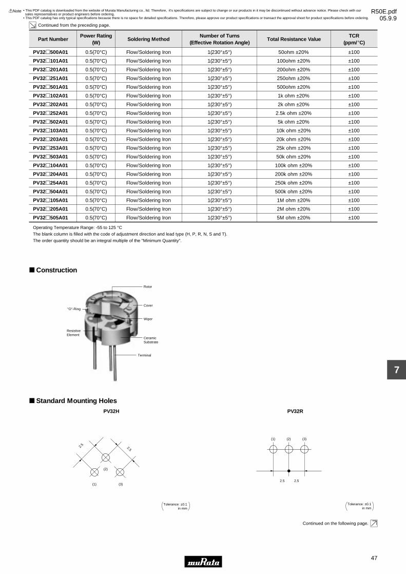
47
7
!Note • Please read rating and !CAUTION (for storage, operating, rating, soldering, mounting and handling) in this catalog to prevent smoking and/or burning, etc.• This catalog has only typical specifications because there is no space for detailed specifications. Therefore, please approve our product specifications or transact the approval sheet for product specifications before ordering.
Part NumberPower Rating
(W)Soldering Method
Number of Turns(Effective Rotation Angle)
Total Resistance ValueTCR
(ppm/°C)
Continued from the preceding page.
PV32p500A01 0.5(70°C) Flow/Soldering Iron 1(230°±5°) 50ohm ±20% ±100
PV32p101A01 0.5(70°C) Flow/Soldering Iron 1(230°±5°) 100ohm ±20% ±100
PV32p201A01 0.5(70°C) Flow/Soldering Iron 1(230°±5°) 200ohm ±20% ±100
PV32p251A01 0.5(70°C) Flow/Soldering Iron 1(230°±5°) 250ohm ±20% ±100
PV32p501A01 0.5(70°C) Flow/Soldering Iron 1(230°±5°) 500ohm ±20% ±100
PV32p102A01 0.5(70°C) Flow/Soldering Iron 1(230°±5°) 1k ohm ±20% ±100
PV32p202A01 0.5(70°C) Flow/Soldering Iron 1(230°±5°) 2k ohm ±20% ±100
PV32p252A01 0.5(70°C) Flow/Soldering Iron 1(230°±5°) 2.5k ohm ±20% ±100
PV32p502A01 0.5(70°C) Flow/Soldering Iron 1(230°±5°) 5k ohm ±20% ±100
PV32p103A01 0.5(70°C) Flow/Soldering Iron 1(230°±5°) 10k ohm ±20% ±100
PV32p203A01 0.5(70°C) Flow/Soldering Iron 1(230°±5°) 20k ohm ±20% ±100
PV32p253A01 0.5(70°C) Flow/Soldering Iron 1(230°±5°) 25k ohm ±20% ±100
PV32p503A01 0.5(70°C) Flow/Soldering Iron 1(230°±5°) 50k ohm ±20% ±100
PV32p104A01 0.5(70°C) Flow/Soldering Iron 1(230°±5°) 100k ohm ±20% ±100
PV32p204A01 0.5(70°C) Flow/Soldering Iron 1(230°±5°) 200k ohm ±20% ±100
PV32p254A01 0.5(70°C) Flow/Soldering Iron 1(230°±5°) 250k ohm ±20% ±100
PV32p504A01 0.5(70°C) Flow/Soldering Iron 1(230°±5°) 500k ohm ±20% ±100
PV32p105A01 0.5(70°C) Flow/Soldering Iron 1(230°±5°) 1M ohm ±20% ±100
PV32p205A01 0.5(70°C) Flow/Soldering Iron 1(230°±5°) 2M ohm ±20% ±100
PV32p505A01 0.5(70°C) Flow/Soldering Iron 1(230°±5°) 5M ohm ±20% ±100
Operating Temperature Range: -55 to 125 °CThe blank column is filled with the code of adjustment direction and lead type (H, P, R, N, S and T).
The order quantity should be an integral multiple of the "Minimum Quantity".
Construction
"O"-Ring
ResistiveElement
Rotor
Cover
Terminal
Wiper
CeramicSubstrate
Standard Mounting HolesPV32H
(1) (3)
(2)
2.52.
5
Tolerance: ±0.1in mm
PV32R
2.5 2.5
(2)(1) (3)
Tolerance: ±0.1in mm
Continued on the following page.
• This PDF catalog is downloaded from the website of Murata Manufacturing co., ltd. Therefore, it’s specifications are subject to change or our products in it may be discontinued without advance notice. Please check with our sales representatives or product engineers before ordering.
• This PDF catalog has only typical specifications because there is no space for detailed specifications. Therefore, please approve our product specifications or transact the approval sheet for product specifications before ordering.
!Note R50E.pdf05.9.9

48
7
!Note • Please read rating and !CAUTION (for storage, operating, rating, soldering, mounting and handling) in this catalog to prevent smoking and/or burning, etc.• This catalog has only typical specifications because there is no space for detailed specifications. Therefore, please approve our product specifications or transact the approval sheet for product specifications before ordering.
Continued from the preceding page.
Standard Mounting HolesPV32P/PV32S
2.5 2.5
2.5
(2)
(1)
(3)
Tolerance: ±0.1in mm
PV32N
(3) (1)
(2)
2.5
2.5
2.5
Tolerance: ±0.1in mm
PV32T
2.5 2.5
2.5
(2)
(3)(1)
Tolerance: ±0.1in mm
Characteristics∆TR ±2%
∆V.S.S. ±1%
∆TR ±2%
IR 100M ohm min.
∆TR ±1%
∆V.S.S. ±1%
∆TR ±1%
∆V.S.S. ±1%
∆TR ±2%
∆V.S.S. ±2%
∆TR ±2%
∆V.S.S. ±1%
∆TR ±2%
∆V.S.S. ±1%
∆TR ±4%
Temperature Cycle
Humidity
Vibration (20G)
Shock (100G)
Temperature Load Life
Low Temperature Exposure
High Temperature Exposure
Rotational Life (200 cycles)
∆TR : Total Resistance Change
∆V.S.S. : Voltage Setting Stability
IR : Insulation Resistance
• This PDF catalog is downloaded from the website of Murata Manufacturing co., ltd. Therefore, it’s specifications are subject to change or our products in it may be discontinued without advance notice. Please check with our sales representatives or product engineers before ordering.
• This PDF catalog has only typical specifications because there is no space for detailed specifications. Therefore, please approve our product specifications or transact the approval sheet for product specifications before ordering.
!Note R50E.pdf05.9.9

49
7
!Note • Please read rating and !CAUTION (for storage, operating, rating, soldering, mounting and handling) in this catalog to prevent smoking and/or burning, etc.• This catalog has only typical specifications because there is no space for detailed specifications. Therefore, please approve our product specifications or transact the approval sheet for product specifications before ordering.
PV34 Series
Features1. 5 standard terminal styles2. Sealed construction protects the interior from dust and liquid, which achieves stable performance.3. Available for ultrasonic cleaning after soldering4. Flammability: UL94V-05. To be complied with RoHS directive by new Cd free cermet resistive material. Pb free terminals with Sn plating.
Applications1. HDTVs 2. Professional cameras 3. CATV 4. Printers5. Sensors 6. Switching power supplies
#2
#1 #3
CLOCKWISE
#1
#2
#3
9.6
3−0.
5±0.
1 D
ia.
3.8
Dia
.
0.8
5.3
9.6
5.1
2.2±
0.4
4.9
0.3
5.5±0.5
2.5 2.5
1.0
Dep
th
Tolerance : ±0.3 ( in mm)
PV34F
#2
#1 #3
CLOCKWISE
#1 #2 #3
9.6
5.3
9.6
5.5±
0.5
4.9
2.5 2.5
2.5
1.4±
0.4
0.4
3.8
DIA
. 0.8
1.0
Dep
th
3−0.5±0.1 DIA.
Tolerance: ±0.3in mm( (
PV34H
#2
#1 #3
CLOCKWISE
#1
#2
#3
9.6
3−0.
5±0.
1 D
ia.
3.8
Dia
.
0.8
5.3
9.6
2.5
4.8±
0.4
4.9
0.3
5.5±0.5
2.5 2.5
1.0
Dep
th
Tolerance : ±0.3 ( in mm)PV34P
#1 #2 #3
9.6
5.3
9.6
5.5±
0.5
4.9
2.5 2.5
2.4±
0.4
0.4
3.8
Dia
. 0.8
1.0
Dep
th
3−0.5±0.1 Dia.
Tolerance : ±0.3 ( in mm)
#2
#1 #3
CLOCKWISEPV34W
#2
#1 #3
CLOCKWISE
#1#2#3
9.6
5.3
9.6
5.5±
0.5
4.9
2.5 2.5
2.5
1.4±
0.4
0.4
3.8
Dia
. 0.8
1.0
Dep
th
3−0.5±0.1 Dia.
Tolerance : ±0.3 ( in mm)PV34X
• This PDF catalog is downloaded from the website of Murata Manufacturing co., ltd. Therefore, it’s specifications are subject to change or our products in it may be discontinued without advance notice. Please check with our sales representatives or product engineers before ordering.
• This PDF catalog has only typical specifications because there is no space for detailed specifications. Therefore, please approve our product specifications or transact the approval sheet for product specifications before ordering.
!Note R50E.pdf05.9.9

50
7
!Note • Please read rating and !CAUTION (for storage, operating, rating, soldering, mounting and handling) in this catalog to prevent smoking and/or burning, etc.• This catalog has only typical specifications because there is no space for detailed specifications. Therefore, please approve our product specifications or transact the approval sheet for product specifications before ordering.
Part NumberPower Rating
(W)Soldering Method
Number of Turns(Effective Rotation Angle)
Total Resistance ValueTCR
(ppm/°C)
PV34p100C01 0.5(70°C) Flow/Soldering Iron 1(280°±15°) 10ohm ±10% ±150
PV34p200C01 0.5(70°C) Flow/Soldering Iron 1(280°±15°) 20ohm ±10% ±150
PV34p500C01 0.5(70°C) Flow/Soldering Iron 1(280°±15°) 50ohm ±10% ±150
PV34p101C01 0.5(70°C) Flow/Soldering Iron 1(280°±15°) 100ohm ±10% ±150
PV34p201C01 0.5(70°C) Flow/Soldering Iron 1(280°±15°) 200ohm ±10% ±100
PV34p501C01 0.5(70°C) Flow/Soldering Iron 1(280°±15°) 500ohm ±10% ±100
PV34p102C01 0.5(70°C) Flow/Soldering Iron 1(280°±15°) 1k ohm ±10% ±100
PV34p202C01 0.5(70°C) Flow/Soldering Iron 1(280°±15°) 2k ohm ±10% ±100
PV34p502C01 0.5(70°C) Flow/Soldering Iron 1(280°±15°) 5k ohm ±10% ±100
PV34p103C01 0.5(70°C) Flow/Soldering Iron 1(280°±15°) 10k ohm ±10% ±100
PV34p203C01 0.5(70°C) Flow/Soldering Iron 1(280°±15°) 20k ohm ±10% ±100
PV34p253C01 0.5(70°C) Flow/Soldering Iron 1(280°±15°) 25k ohm ±10% ±100
PV34p503C01 0.5(70°C) Flow/Soldering Iron 1(280°±15°) 50k ohm ±10% ±100
PV34p104C01 0.5(70°C) Flow/Soldering Iron 1(280°±15°) 100k ohm ±10% ±100
PV34p204C01 0.5(70°C) Flow/Soldering Iron 1(280°±15°) 200k ohm ±10% ±100
PV34p254C01 0.5(70°C) Flow/Soldering Iron 1(280°±15°) 250k ohm ±10% ±100
PV34p504C01 0.5(70°C) Flow/Soldering Iron 1(280°±15°) 500k ohm ±10% ±100
PV34p105C01 0.5(70°C) Flow/Soldering Iron 1(280°±15°) 1M ohm ±10% ±100
PV34p205C01 0.5(70°C) Flow/Soldering Iron 1(280°±15°) 2M ohm ±10% ±100
Operating Temperature Range: -55 to 125 °CThe blank column is filled with the code of adjustment direction and lead type (F, H, P, X and W).
The order quantity should be an integral multiple of the "Minimum Quantity".
Construction
Case
Rotor
"O"-Ring
Alumina Substrate
Terminal
Wiper
Cermet ResistiveElement
Standard Mounting HolesPV34F
2.5
5.1
(2)
(3)(1)
2.5
Tolerance: ±0.1in mm
PV34H/PV34P
2.5 2.5
2.5
(2)
(3)(1)
Tolerance: ±0.1in mm
Continued on the following page.
• This PDF catalog is downloaded from the website of Murata Manufacturing co., ltd. Therefore, it’s specifications are subject to change or our products in it may be discontinued without advance notice. Please check with our sales representatives or product engineers before ordering.
• This PDF catalog has only typical specifications because there is no space for detailed specifications. Therefore, please approve our product specifications or transact the approval sheet for product specifications before ordering.
!Note R50E.pdf05.9.9

51
7
!Note • Please read rating and !CAUTION (for storage, operating, rating, soldering, mounting and handling) in this catalog to prevent smoking and/or burning, etc.• This catalog has only typical specifications because there is no space for detailed specifications. Therefore, please approve our product specifications or transact the approval sheet for product specifications before ordering.
Continued from the preceding page.
Standard Mounting HolesPV34W
2.5 2.5
(2)(1) (3)
Tolerance: ±0.1in mm
PV34X
(3) (1)
(2)
2.5
2.5
2.5
Tolerance: ±0.1in mm
Characteristics∆TR ±2%
∆V.S.S. ±1%
∆TR ±2%
IR 100M ohm min.
∆TR ±1%
∆V.S.S. ±1%
∆TR ±1%
∆V.S.S. ±1%
∆TR ±2%
∆V.S.S. ±2%
∆TR ±1%
∆V.S.S. ±1%
∆TR ±2%
∆V.S.S. ±1%
∆TR RV100k ohm ... ±3%
RG100k ohm ... ±5%
Temperature Cycle
Humidity
Vibration (20G)
Shock (100G)
Temperature Load Life
Low Temperature Exposure
High Temperature Exposure
Rotational Life (200 cycles)
∆TR : Total Resistance Change
∆V.S.S. : Voltage Setting Stability
IR : Insulation Resistance
R : Standard Total Resistance
• This PDF catalog is downloaded from the website of Murata Manufacturing co., ltd. Therefore, it’s specifications are subject to change or our products in it may be discontinued without advance notice. Please check with our sales representatives or product engineers before ordering.
• This PDF catalog has only typical specifications because there is no space for detailed specifications. Therefore, please approve our product specifications or transact the approval sheet for product specifications before ordering.
!Note R50E.pdf05.9.9

PVC6/PV32/PV34 Series Notice
52
7
!Note • Please read rating and !CAUTION (for storage, operating, rating, soldering, mounting and handling) in this catalog to prevent smoking and/or burning, etc.• This catalog has only typical specifications because there is no space for detailed specifications. Therefore, please approve our product specifications or transact the approval sheet for product specifications before ordering.
Notice (Operating and Storage Conditions)1. Store in temperatures of -10 to +40 deg. C and relative humidity of 30-85%RH.2. Do not store in or near corrosive gases.3. Use within six months after delivery. 4. Open the package just before using.5. Do not store under direct sunlight.6. If you use the trimmer potentiometer in an environment other than listed below, please consult with a Murata factory representative prior to using. The trimmer potentiometer should not be used under the following environmental conditions:
(1) Corrosive gaseous atmosphere (Ex. Chlorine gas, Hydrogen sulfide gas, Ammonia gas, Sulfuric acid gas, Nitric oxide gas, etc.) (2) In liquid (Ex. Oil, Medical liquid, Organic solvent, etc.) (3) Dusty/dirty atmosphere (4) Direct sunlight (5) Static voltage nor electric/magnetic fields (6) Direct sea breeze (7) Other variations of the above
Notice (Rating)1. When using with partial load (rheostat), minimize the power depending on the resistance value.2. The maximum input voltage to a trimmer potentiometer should not exceed (P•R)^1/2 or the maximum operating voltage, whichever is smaller.3. The maximum input current to a trimmer potentiometer should not exceed (P/R)^1/2 or the allowable wiper current, whichever is smaller.
Notice (Soldering and Mounting)1. Soldering (1) Soldering condition Refer to the temperature profile. If the soldering conditions are not suitable, e.g., excessive time and/or excessive temperature, the trimmer potentiometer may deviate from the specified characteristics. (2) To minimize mechanical stress when adjusting, the trimmer potentiometer should be mounted onto PCB without gap. (3) The soldering iron should not come in contact with the case of the trimmer potentiometer. If such contact does occur, the trimmer potentiometer may be damaged.2. Mounting (1) Use PCB hole to meet the pin of the trimmer potentiometer. If the trimmer potentiometer installs into insufficient PCB hole, the trimmer potentimeter may be damaged by mechanical stress. (2) Do not apply excessive force (preferably 9.8N (Ref.; 1kgf) max.), when the trimmer potentiometer is mounted to the PCB.
3. Cleaning (1) Isopropyl-alcohol and Ethyl-alcohol are applicable solvents for cleaning. If you use any other types of solvents, please consult with a Murata factory representative prior to using. (2) The total cleaning time by cold dipping, vapor and ultrasonic washing (conditions as below) method should be less than 3 minutes. (3) For ultra-sonic cleaning, the available condition is as follows. >Power: 600W (67 liter) max. >Frequency: 28kHz >Temperature: Ambient temperature Due to the ultra-sonic cleaning equipment's peculiar self-resonance point and that the cleaning compatibility usually depends on the jig construction and/or the cleaning condition such as the depth of immersion, please check the cleaning equipment to determine the suitable conditions.If the trimmer potentiometer is cleaned by other conditions, the trimmer potentiometer may be damaged.
• This PDF catalog is downloaded from the website of Murata Manufacturing co., ltd. Therefore, it’s specifications are subject to change or our products in it may be discontinued without advance notice. Please check with our sales representatives or product engineers before ordering.
• This PDF catalog has only typical specifications because there is no space for detailed specifications. Therefore, please approve our product specifications or transact the approval sheet for product specifications before ordering.
!Note R50E.pdf05.9.9
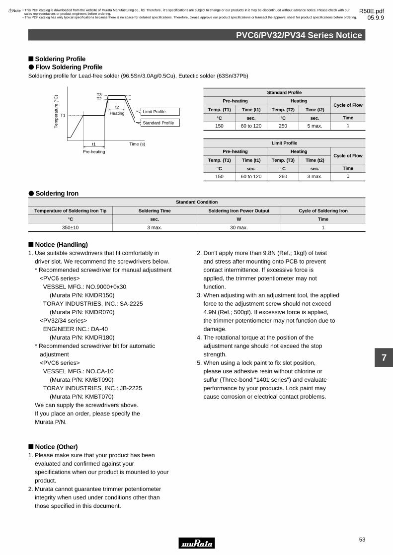
PVC6/PV32/PV34 Series Notice
53
7
!Note • Please read rating and !CAUTION (for storage, operating, rating, soldering, mounting and handling) in this catalog to prevent smoking and/or burning, etc.• This catalog has only typical specifications because there is no space for detailed specifications. Therefore, please approve our product specifications or transact the approval sheet for product specifications before ordering.
Soldering Profile Flow Soldering ProfileSoldering profile for Lead-free solder (96.5Sn/3.0Ag/0.5Cu), Eutectic solder (63Sn/37Pb)
Tem
pera
ture
(°C
)
t1
t2
T3T2
T1
Time (s)
Limit Profile
Standard Profile
Heating
Pre-heating
Standard Profile
Pre-heating Heating
Temp. (T1)
°C
Time (t1)
sec.
Temp. (T2)
°C
Time (t2)
sec.
150 60 to 120 250 5 max. 1
Cycle of Flow
Time
Limit Profile
Pre-heating Heating
Temp. (T1)
°C
Time (t1)
sec.
Temp. (T3)
°C
Time (t2)
sec.
150 60 to 120 260 3 max. 1
Cycle of Flow
Time
Standard Condition
Temperature of Soldering Iron Tip
°C
Soldering Time
sec.
Soldering Iron Power Output
W
350±10 3 max. 30 max. 1
Cycle of Soldering Iron
Time
Soldering Iron
Notice (Handling)1. Use suitable screwdrivers that fit comfortably in driver slot. We recommend the screwdrivers below. * Recommended screwdriver for manual adjustment <PVC6 series> VESSEL MFG.: NO.9000+0x30 (Murata P/N: KMDR150) TORAY INDUSTRIES, INC.: SA-2225 (Murata P/N: KMDR070) <PV32/34 series> ENGINEER INC.: DA-40 (Murata P/N: KMDR180) * Recommended screwdriver bit for automatic adjustment <PVC6 series> VESSEL MFG.: NO.CA-10 (Murata P/N: KMBT090) TORAY INDUSTRIES, INC.: JB-2225 (Murata P/N: KMBT070) We can supply the screwdrivers above. If you place an order, please specify the Murata P/N.
2. Don't apply more than 9.8N (Ref.; 1kgf) of twist and stress after mounting onto PCB to prevent contact intermittence. If excessive force is applied, the trimmer potentiometer may not function.3. When adjusting with an adjustment tool, the applied force to the adjustment screw should not exceed 4.9N (Ref.; 500gf). If excessive force is applied, the trimmer potentiometer may not function due to damage.4. The rotational torque at the position of the adjustment range should not exceed the stop strength.5. When using a lock paint to fix slot position, please use adhesive resin without chlorine or sulfur (Three-bond "1401 series") and evaluate performance by your products. Lock paint may cause corrosion or electrical contact problems.
Notice (Other)1. Please make sure that your product has been evaluated and confirmed against your specifications when our product is mounted to your product.2. Murata cannot guarantee trimmer potentiometer integrity when used under conditions other than those specified in this document.
• This PDF catalog is downloaded from the website of Murata Manufacturing co., ltd. Therefore, it’s specifications are subject to change or our products in it may be discontinued without advance notice. Please check with our sales representatives or product engineers before ordering.
• This PDF catalog has only typical specifications because there is no space for detailed specifications. Therefore, please approve our product specifications or transact the approval sheet for product specifications before ordering.
!Note R50E.pdf05.9.9

54
8
!Note • Please read rating and !CAUTION (for storage, operating, rating, soldering, mounting and handling) in this catalog to prevent smoking and/or burning, etc.• This catalog has only typical specifications because there is no space for detailed specifications. Therefore, please approve our product specifications or transact the approval sheet for product specifications before ordering.
Trimmer PotentiometersLead Sealed Type Multi-turns PV12/PV37/PV23/PV22/PV36 Series
PV12 Series
Features1. The unique inner gear system recognizes the position of the center of the shaft of the potentiometer.2. Sealed construction protects the interior from dust and liquid, which achieves stable performance.3. Available for ultrasonic cleaning after soldering4. Clutch mechanism prevents excessive wiper rotation.
Applications1. HDTVs 2. Professional cameras 3. CATV 4. FAX5. Printers 6. Sensors 7. Switching power supplies
#2
#1 #3
CLOCKWISE
#1
#2
#3
0.6±0.10.7±0.1 Depth
2.5±
0.1
7.6±
0.1
Dia
.
6.6±0.1 7.0±1.0
0.5
3−0.
5±0.
1 D
ia.
0.4±
0.1
90°±6°
2.5±0
.2 2.5±0.2
Tolerance : ±0.3 ( in mm)PV12H
#2
#1 #3
CLOCKWISE#1
#2
#3
0.6±0.10.7±0.1 Depth
2.5±
0.1
7.6±
0.1
Dia
.
6.6±0.1 7.0±1.0
0.5
3−0.
5±0.
1 D
ia.
2.5
2.5 2.5
Tolerance : ±0.3 ( in mm)PV12P
#2
#1 #3
CLOCKWISE
#1 #2 #37.6±0.3
0.6±0.1
9.0±
0.3
5.1±
0.3
7.7±0.3
6.3±0.3
3−0.5±0.1 Dia.7.0±
1.0
0.5
2.5±
0.1
3.6
2.5
2.5 2.5
0.7±0.1 Depth
Tolerance : ±0.3 ( in mm)
PV12S
#2
#1 #3
CLOCKWISE
#1 #2 #37.6±0.3
0.6±0.1
9.0±
0.3
5.1±
0.3
7.7±0.3
6.3±0.3
3−0.5±0.1 Dia.7.0±
1.0
0.5
2.5±
0.1
3.6
2.5
2.5 2.5
0.7±0.1 Depth
Tolerance : ±0.3 ( in mm)
PV12T
Part NumberPower Rating
(W)Soldering Method
Number of Turns(Effective Rotation Angle)
Total Resistance ValueTCR
(ppm/°C)
PV12p100A01 0.5(70°C) Flow/Soldering Iron 4 10ohm ±10% ±100
PV12p200A01 0.5(70°C) Flow/Soldering Iron 4 20ohm ±10% ±100
PV12p500A01 0.5(70°C) Flow/Soldering Iron 4 50ohm ±10% ±100
PV12p101A01 0.5(70°C) Flow/Soldering Iron 4 100ohm ±10% ±100
PV12p201A01 0.5(70°C) Flow/Soldering Iron 4 200ohm ±10% ±100
PV12p501A01 0.5(70°C) Flow/Soldering Iron 4 500ohm ±10% ±100
PV12p102A01 0.5(70°C) Flow/Soldering Iron 4 1k ohm ±10% ±100
PV12p202A01 0.5(70°C) Flow/Soldering Iron 4 2k ohm ±10% ±100
PV12p502A01 0.5(70°C) Flow/Soldering Iron 4 5k ohm ±10% ±100
PV12p103A01 0.5(70°C) Flow/Soldering Iron 4 10k ohm ±10% ±100
Continued on the following page.
• This PDF catalog is downloaded from the website of Murata Manufacturing co., ltd. Therefore, it’s specifications are subject to change or our products in it may be discontinued without advance notice. Please check with our sales representatives or product engineers before ordering.
• This PDF catalog has only typical specifications because there is no space for detailed specifications. Therefore, please approve our product specifications or transact the approval sheet for product specifications before ordering.
!Note R50E.pdf05.9.9

55
8
!Note • Please read rating and !CAUTION (for storage, operating, rating, soldering, mounting and handling) in this catalog to prevent smoking and/or burning, etc.• This catalog has only typical specifications because there is no space for detailed specifications. Therefore, please approve our product specifications or transact the approval sheet for product specifications before ordering.
Part NumberPower Rating
(W)Soldering Method
Number of Turns(Effective Rotation Angle)
Total Resistance ValueTCR
(ppm/°C)
Continued from the preceding page.
PV12p203A01 0.5(70°C) Flow/Soldering Iron 4 20k ohm ±10% ±100
PV12p503A01 0.5(70°C) Flow/Soldering Iron 4 50k ohm ±10% ±100
PV12p104A01 0.5(70°C) Flow/Soldering Iron 4 100k ohm ±10% ±100
PV12p204A01 0.5(70°C) Flow/Soldering Iron 4 200k ohm ±10% ±100
PV12p504A01 0.5(70°C) Flow/Soldering Iron 4 500k ohm ±10% ±100
PV12p105A01 0.5(70°C) Flow/Soldering Iron 4 1M ohm ±10% ±100
PV12p205A01 0.5(70°C) Flow/Soldering Iron 4 2M ohm ±10% ±100
Operating Temperature Range: -55 to 125 °CThe blank column is filled with the code of adjustment direction and lead type (H, P, T and S).
The order quantity should be an integral multiple of the "Minimum Quantity".
Construction
Gear
Rotor
Terminal
Wiper
Insert
"O"-Ring
Case
Shaft
Ceramic ResistiveElement
Alumina Substrate
Standard Mounting HolesPV12H
(1) (3)
(2)
2.52.
5
Tolerance: ±0.1in mm
PV12P/PV12S
2.5 2.5
2.5
(2)
(1)
(3)
Tolerance: ±0.1in mm
PV12T
2.5 2.5
2.5
(2)
(3)(1)
Tolerance: ±0.1in mm
• This PDF catalog is downloaded from the website of Murata Manufacturing co., ltd. Therefore, it’s specifications are subject to change or our products in it may be discontinued without advance notice. Please check with our sales representatives or product engineers before ordering.
• This PDF catalog has only typical specifications because there is no space for detailed specifications. Therefore, please approve our product specifications or transact the approval sheet for product specifications before ordering.
!Note R50E.pdf05.9.9

56
8
!Note • Please read rating and !CAUTION (for storage, operating, rating, soldering, mounting and handling) in this catalog to prevent smoking and/or burning, etc.• This catalog has only typical specifications because there is no space for detailed specifications. Therefore, please approve our product specifications or transact the approval sheet for product specifications before ordering.
Characteristics∆TR ±2%
∆V.S.S. ±1%
∆TR ±2%
IR 100M ohm min.
∆TR ±1%
∆V.S.S. ±1%
∆TR ±1%
∆V.S.S. ±1%
∆TR ±3%
∆V.S.S. ±2%
∆TR ±3%
∆V.S.S. ±1.5%
∆TR ±3%
∆V.S.S. ±1.5%
∆TR ±3%
Temperature Cycle
Humidity
Vibration (20G)
Shock (100G)
Temperature Load Life
Low Temperature Exposure
High Temperature Exposure
Rotational Life (200 cycles)
∆TR : Total Resistance Change
∆V.S.S. : Voltage Setting Stability
IR : Insulation Resistance
• This PDF catalog is downloaded from the website of Murata Manufacturing co., ltd. Therefore, it’s specifications are subject to change or our products in it may be discontinued without advance notice. Please check with our sales representatives or product engineers before ordering.
• This PDF catalog has only typical specifications because there is no space for detailed specifications. Therefore, please approve our product specifications or transact the approval sheet for product specifications before ordering.
!Note R50E.pdf05.9.9

57
8
!Note • Please read rating and !CAUTION (for storage, operating, rating, soldering, mounting and handling) in this catalog to prevent smoking and/or burning, etc.• This catalog has only typical specifications because there is no space for detailed specifications. Therefore, please approve our product specifications or transact the approval sheet for product specifications before ordering.
PV37 Series
Features1. Smaller volume (about one-third) than 25-turns potentiometer 2. Sealed construction protects the interior from dust and liquid, which achieves stable performance.3. Available for ultrasonic cleaning after soldering4. Clutch mechanism prevents excessive wiper rotation.5. 5 standard terminal styles6. Both top and side adjustment directions7. To be complied with RoHS directive by new Cd free cermet resistive material. Pb free terminals with Sn plating.
Applications1. Measuring instruments 2. OA equipment3. Medical equipment 4. Power supply5. Base station for cellular phone
#2
#1 #3
CLOCKWISE
#1 #2 #3
6.4
2.5
0.7
2.5
6.7
1.8±
0.2
Dia
.
1.2
1.1
5.0±
1.0
4.0
3−0.4±0.1 Dia.
0.6±
0.2
1.00.6
2.5
Marking
Tolerance : ±0.3 ( in mm)
PV37P
#1#2#3
6.41.2
2.5
0.7
2.5
6.7
1.8±0.2 Dia.1.1
5.0±
1.0
3−0.4±0.1 Dia.
0.6±0.2
1.00.6
2.5
4.0
#2
#1 #3
CLOCKWISE
Marking
Tolerance : ±0.3 ( in mm)
PV37W
#2
#1 #3
CLOCKWISE
#1#2#3
6.4
Marking
1.1
2.5
0.7
2.5
6.7
1.8±
0.2
Dia
.
1.1
5.0±
1.0
3−0.4±0.1 Dia.0.
6±0.
2
1.00.6
2.5
4.0
Tolerance : ±0.3 ( in mm)
PV37X
6.4
6.7
5.0±
1.0
1.2
3−0.4±0.1 Dia.
1.8±0.2 Dia.
0.6±0.2
#1#2#3
2.5 2.5
4.0
2.0
1.1
1.00.6
#2
#1 #3
CLOCKWISE
Marking
Tolerance : ±0.3 ( in mm)PV37Y
6.4
6.7
5.0±
1.0
3−0.4±0.1 Dia.
1.8±
0.2
Dia
.
0.6±
0.2
#1#2#32.5 2.5
4.0
2.0
1.1
1.1
0.6
1.0
#2
#1 #3
CLOCKWISE
Marking
Tolerance : ±0.3 ( in mm)
PV37Z
Part NumberPower Rating
(W)Soldering Method
Number of Turns(Effective Rotation Angle)
Total Resistance ValueTCR
(ppm/°C)
PV37p100C01 0.25(85°C) Flow/Soldering Iron 12 10ohm ±10% ±150
PV37p200C01 0.25(85°C) Flow/Soldering Iron 12 20ohm ±10% ±150
PV37p500C01 0.25(85°C) Flow/Soldering Iron 12 50ohm ±10% ±150
Continued on the following page.
• This PDF catalog is downloaded from the website of Murata Manufacturing co., ltd. Therefore, it’s specifications are subject to change or our products in it may be discontinued without advance notice. Please check with our sales representatives or product engineers before ordering.
• This PDF catalog has only typical specifications because there is no space for detailed specifications. Therefore, please approve our product specifications or transact the approval sheet for product specifications before ordering.
!Note R50E.pdf05.9.9

58
8
!Note • Please read rating and !CAUTION (for storage, operating, rating, soldering, mounting and handling) in this catalog to prevent smoking and/or burning, etc.• This catalog has only typical specifications because there is no space for detailed specifications. Therefore, please approve our product specifications or transact the approval sheet for product specifications before ordering.
Part NumberPower Rating
(W)Soldering Method
Number of Turns(Effective Rotation Angle)
Total Resistance ValueTCR
(ppm/°C)
Continued from the preceding page.
PV37p101C01 0.25(85°C) Flow/Soldering Iron 12 100ohm ±10% ±150
PV37p201C01 0.25(85°C) Flow/Soldering Iron 12 200ohm ±10% ±150
PV37p501C01 0.25(85°C) Flow/Soldering Iron 12 500ohm ±10% ±150
PV37p102C01 0.25(85°C) Flow/Soldering Iron 12 1k ohm ±10% ±150
PV37p202C01 0.25(85°C) Flow/Soldering Iron 12 2k ohm ±10% ±150
PV37p502C01 0.25(85°C) Flow/Soldering Iron 12 5k ohm ±10% ±150
PV37p103C01 0.25(85°C) Flow/Soldering Iron 12 10k ohm ±10% ±150
PV37p203C01 0.25(85°C) Flow/Soldering Iron 12 20k ohm ±10% ±150
PV37p253C01 0.25(85°C) Flow/Soldering Iron 12 25k ohm ±10% ±150
PV37p503C01 0.25(85°C) Flow/Soldering Iron 12 50k ohm ±10% ±150
PV37p104C01 0.25(85°C) Flow/Soldering Iron 12 100k ohm ±10% ±150
PV37p204C01 0.25(85°C) Flow/Soldering Iron 12 200k ohm ±10% ±150
PV37p254C01 0.25(85°C) Flow/Soldering Iron 12 250k ohm ±10% ±150
PV37p504C01 0.25(85°C) Flow/Soldering Iron 12 500k ohm ±10% ±150
PV37p105C01 0.25(85°C) Flow/Soldering Iron 12 1M ohm ±10% ±150
PV37p205C01 0.25(85°C) Flow/Soldering Iron 12 2M ohm ±10% ±150
PV37p100C31 0.25(85°C) Flow/Soldering Iron 12 10ohm ±10% ±150
PV37p200C31 0.25(85°C) Flow/Soldering Iron 12 20ohm ±10% ±150
PV37p500C31 0.25(85°C) Flow/Soldering Iron 12 50ohm ±10% ±150
PV37p101C31 0.25(85°C) Flow/Soldering Iron 12 100ohm ±10% ±150
PV37p201C31 0.25(85°C) Flow/Soldering Iron 12 200ohm ±10% ±150
PV37p501C31 0.25(85°C) Flow/Soldering Iron 12 500ohm ±10% ±150
PV37p102C31 0.25(85°C) Flow/Soldering Iron 12 1k ohm ±10% ±150
PV37p202C31 0.25(85°C) Flow/Soldering Iron 12 2k ohm ±10% ±150
PV37p502C31 0.25(85°C) Flow/Soldering Iron 12 5k ohm ±10% ±150
PV37p103C31 0.25(85°C) Flow/Soldering Iron 12 10k ohm ±10% ±150
PV37p203C31 0.25(85°C) Flow/Soldering Iron 12 20k ohm ±10% ±150
PV37p253C31 0.25(85°C) Flow/Soldering Iron 12 25k ohm ±10% ±150
PV37p503C31 0.25(85°C) Flow/Soldering Iron 12 50k ohm ±10% ±150
PV37p104C31 0.25(85°C) Flow/Soldering Iron 12 100k ohm ±10% ±150
PV37p204C31 0.25(85°C) Flow/Soldering Iron 12 200k ohm ±10% ±150
PV37p254C31 0.25(85°C) Flow/Soldering Iron 12 250k ohm ±10% ±150
PV37p504C31 0.25(85°C) Flow/Soldering Iron 12 500k ohm ±10% ±150
PV37p105C31 0.25(85°C) Flow/Soldering Iron 12 1M ohm ±10% ±150
PV37p205C31 0.25(85°C) Flow/Soldering Iron 12 2M ohm ±10% ±150
Operating Temperature Range: -55 to 125 °CThe blank column is filled with the code of adjustment direction and lead type (P, X, Y, W and Z).
The order quantity should be an integral multiple of the "Minimum Quantity".
The last three digits express the individual specification codes. C01 for standard type and C31 for radial taping type (PV37Y/PV37Z series only).
Construction
Gear Case
Terminal
Alumina Substrate
Wiper
Cermet ResistiveElement
Adjustment Screw
• This PDF catalog is downloaded from the website of Murata Manufacturing co., ltd. Therefore, it’s specifications are subject to change or our products in it may be discontinued without advance notice. Please check with our sales representatives or product engineers before ordering.
• This PDF catalog has only typical specifications because there is no space for detailed specifications. Therefore, please approve our product specifications or transact the approval sheet for product specifications before ordering.
!Note R50E.pdf05.9.9

59
8
!Note • Please read rating and !CAUTION (for storage, operating, rating, soldering, mounting and handling) in this catalog to prevent smoking and/or burning, etc.• This catalog has only typical specifications because there is no space for detailed specifications. Therefore, please approve our product specifications or transact the approval sheet for product specifications before ordering.
Standard Mounting HolesPV37P
2.5 2.5
2.5
(2)
(3)(1)
Tolerance: ±0.1in mm
PV37W/PV37X
(3) (1)
(2)
2.5
2.5
2.5
Tolerance: ±0.1in mm
PV37Y/PV37Z
2.5 2.5
(2)(3) (1)
Tolerance: ±0.1in mm
Characteristics∆TR ±1%
∆V.S.S. ±1%
∆TR ±2%
IR 100M ohm min.
∆TR ±1%
∆V.S.S. ±1%
∆TR ±1%
∆V.S.S. ±1%
∆TR ±2%
∆V.S.S. ±1%
∆TR ±1%
∆V.S.S. ±1%
∆TR ±2%
∆V.S.S. ±1%
∆TR RV100 ohm ... ±3%
RG100 ohm ... ±2%
Temperature Cycle
Humidity
Vibration (20G)
Shock (100G)
Temperature Load Life
Low Temperature Exposure
High Temperature Exposure
Rotational Life (200 cycles)
∆TR : Total Resistance Change
∆V.S.S. : Voltage Setting Stability
IR : Insulation Resistance
R : Standard Total Resistance
• This PDF catalog is downloaded from the website of Murata Manufacturing co., ltd. Therefore, it’s specifications are subject to change or our products in it may be discontinued without advance notice. Please check with our sales representatives or product engineers before ordering.
• This PDF catalog has only typical specifications because there is no space for detailed specifications. Therefore, please approve our product specifications or transact the approval sheet for product specifications before ordering.
!Note R50E.pdf05.9.9

60
8
!Note • Please read rating and !CAUTION (for storage, operating, rating, soldering, mounting and handling) in this catalog to prevent smoking and/or burning, etc.• This catalog has only typical specifications because there is no space for detailed specifications. Therefore, please approve our product specifications or transact the approval sheet for product specifications before ordering.
PV23 Series
Features1. Small size (4.6x6.4x19.1mm) and high power rating (0.75W at 70 degree C)2. Sealed construction protects the interior from dust and liquid, which achieves stable performance.3. Available for ultrasonic cleaning after soldering4. Clutch mechanism prevents excessive wiper rotation.5. To be complied with RoHS directive by new Cd free cermet resistive material. Pb free terminals with Sn plating.
Applications1. Measuring instruments 2. FAX3. Copier 4. Printers 5. Sensors
#2
#1 #3
CLOCKWISE
#1 #2 #3
19.1
1.5
0.8
0.6 2.35
Dia
.
4.6
4.9 6.4
5.0±
1.0
12.7 3.3
5.1
2.5
3−0.5±0.1 Dia.0.3
Tolerance : ±0.3 ( in mm)
PV23P
#3#1
#2
#1 #3
CLOCKWISE
#2
19.1
1.5
0.8
0.6 2.35
Dia
.
4.6
4.9 6.4
5.0±
1.0
17.8 0.6
7.6
2.5
3−0.5±0.1 Dia.0.3
Tolerance : ±0.3 ( in mm)PV23Y
Part NumberPower Rating
(W)Soldering Method
Number of Turns(Effective Rotation Angle)
Total Resistance ValueTCR
(ppm/°C)
PV23p100C01 0.75(70°C) Flow/Soldering Iron 15 10ohm ±10% ±150
PV23p200C01 0.75(70°C) Flow/Soldering Iron 15 20ohm ±10% ±150
PV23p500C01 0.75(70°C) Flow/Soldering Iron 15 50ohm ±10% ±150
PV23p101C01 0.75(70°C) Flow/Soldering Iron 15 100ohm ±10% ±150
PV23p201C01 0.75(70°C) Flow/Soldering Iron 15 200ohm ±10% ±100
PV23p501C01 0.75(70°C) Flow/Soldering Iron 15 500ohm ±10% ±100
PV23p102C01 0.75(70°C) Flow/Soldering Iron 15 1k ohm ±10% ±100
PV23p202C01 0.75(70°C) Flow/Soldering Iron 15 2k ohm ±10% ±100
PV23p502C01 0.75(70°C) Flow/Soldering Iron 15 5k ohm ±10% ±100
PV23p103C01 0.75(70°C) Flow/Soldering Iron 15 10k ohm ±10% ±100
PV23p203C01 0.75(70°C) Flow/Soldering Iron 15 20k ohm ±10% ±100
PV23p503C01 0.75(70°C) Flow/Soldering Iron 15 50k ohm ±10% ±100
PV23p104C01 0.75(70°C) Flow/Soldering Iron 15 100k ohm ±10% ±100
PV23p204C01 0.75(70°C) Flow/Soldering Iron 15 200k ohm ±10% ±100
PV23p504C01 0.75(70°C) Flow/Soldering Iron 15 500k ohm ±10% ±100
PV23p105C01 0.75(70°C) Flow/Soldering Iron 15 1M ohm ±10% ±100
PV23p205C01 0.75(70°C) Flow/Soldering Iron 15 2M ohm ±10% ±100
Operating Temperature Range: -55 to 125 °CThe blank column is filled with the code of adjustment direction and lead type (P and Y).
The order quantity should be an integral multiple of the "Minimum Quantity".
• This PDF catalog is downloaded from the website of Murata Manufacturing co., ltd. Therefore, it’s specifications are subject to change or our products in it may be discontinued without advance notice. Please check with our sales representatives or product engineers before ordering.
• This PDF catalog has only typical specifications because there is no space for detailed specifications. Therefore, please approve our product specifications or transact the approval sheet for product specifications before ordering.
!Note R50E.pdf05.9.9

61
8
!Note • Please read rating and !CAUTION (for storage, operating, rating, soldering, mounting and handling) in this catalog to prevent smoking and/or burning, etc.• This catalog has only typical specifications because there is no space for detailed specifications. Therefore, please approve our product specifications or transact the approval sheet for product specifications before ordering.
Construction
Alumina Substrate
Wiper
Post
Case
Terminal
CermetResistiveElement
AdjustmentScrew
Standard Mounting HolesPV23P
12.7
5.1
2.5
(2)
(3)(1)
Tolerance: ±0.1in mm
PV23Y
17.8
7.6
2.5
(2)
(3)(1)
Tolerance: ±0.1in mm
Characteristics∆TR ±2%
∆V.S.S. ±1%
∆TR ±2%
IR 100M ohm min.
∆TR ±1%
∆V.S.S. ±1%
∆TR ±1%
∆V.S.S. ±1%
∆TR ±3%
∆V.S.S. ±1%
∆TR ±1%
∆V.S.S. ±1%
∆TR ±2%
∆V.S.S. ±1%
∆TR ±3%
Temperature Cycle
Humidity
Vibration (20G)
Shock (50G)
Temperature Load Life
Low Temperature Exposure
High Temperature Exposure
Rotational Life (200 cycles)
∆TR : Total Resistance Change
∆V.S.S. : Voltage Setting Stability
IR : Insulation Resistance
• This PDF catalog is downloaded from the website of Murata Manufacturing co., ltd. Therefore, it’s specifications are subject to change or our products in it may be discontinued without advance notice. Please check with our sales representatives or product engineers before ordering.
• This PDF catalog has only typical specifications because there is no space for detailed specifications. Therefore, please approve our product specifications or transact the approval sheet for product specifications before ordering.
!Note R50E.pdf05.9.9

62
8
!Note • Please read rating and !CAUTION (for storage, operating, rating, soldering, mounting and handling) in this catalog to prevent smoking and/or burning, etc.• This catalog has only typical specifications because there is no space for detailed specifications. Therefore, please approve our product specifications or transact the approval sheet for product specifications before ordering.
PV22 Series
Features1. High power rating (1W at 70 degree C)2. Sealed construction protects the interior from dust and liquid, which achieves stable performance.3. Available for ultrasonic cleaning after soldering4. Clutch mechanism prevents excessive wiper rotation.5. To be complied with RoHS directive by new Cd free cermet resistive material. Pb free terminals with Sn plating.
Applications1. Measuring instruments 2. FAX3. Copier 4. Printers 5. Sensors
#2
#1 #3
CLOCKWISE
#1(Yellow)
#2(Red)
#3(Green)
31.8
25.4±0.2 3.2±0.2
1.7
3.0±
0.2
Dia
.
0.8±0.2
152 min.
6.0
4.7±
0.2
5.0
1.9
8.0±
0.4
Insulated standard wire
4.6
0.6±
0.2
6.0
0.6±
0.2
Mounting holes 2−2.5±0.2 Dia.
Tolerance : ±0.3 ( in mm)PV22L
#2
#1 #3
CLOCKWISE
#1#2 #3
31.8
25.4±0.2 3.2±0.2
1.7
3.0±
0.2
Dia
.
0.8±0.2
6.0
4.7±
0.2
5.0
1.9
4.6
0.6±
0.2
6.0
Mounting holes 2−2.5±0.2 Dia.
3−0.7±0.1 Dia.
17.8 6.6
22.9
8.0±
0.4
7.0±
1.0
Tolerance : ±0.3 ( in mm)PV22S
#2
#1 #3
CLOCKWISE
#1 #2 #3
31.8
25.4±0.2 3.2±0.2
1.7
3.0±
0.2
Dia
.
0.8±0.2
6.0
4.7±
0.2
5.0
1.9
8.0±
0.4
4.6
0.6±
0.2
6.0
Mounting holes 2−2.5±0.2 Dia.
3−0.7±0.1 Dia.
17.8
6.67.6
7.0±
1.0
2.5
Tolerance : ±0.3 ( in mm)PV22Y
Part NumberPower Rating
(W)Soldering Method
Number of Turns(Effective Rotation Angle)
Total Resistance ValueTCR
(ppm/°C)
PV22p100C01 1.0(70°C) Flow/Soldering Iron 22 10ohm ±10% ±100
PV22p200C01 1.0(70°C) Flow/Soldering Iron 22 20ohm ±10% ±100
PV22p500C01 1.0(70°C) Flow/Soldering Iron 22 50ohm ±10% ±100
PV22p101C01 1.0(70°C) Flow/Soldering Iron 22 100ohm ±10% ±100
PV22p201C01 1.0(70°C) Flow/Soldering Iron 22 200ohm ±10% ±100
PV22p501C01 1.0(70°C) Flow/Soldering Iron 22 500ohm ±10% ±100
PV22p102C01 1.0(70°C) Flow/Soldering Iron 22 1k ohm ±10% ±100
PV22p202C01 1.0(70°C) Flow/Soldering Iron 22 2k ohm ±10% ±100
PV22p502C01 1.0(70°C) Flow/Soldering Iron 22 5k ohm ±10% ±100
PV22p103C01 1.0(70°C) Flow/Soldering Iron 22 10k ohm ±10% ±100
PV22p203C01 1.0(70°C) Flow/Soldering Iron 22 20k ohm ±10% ±100
PV22p503C01 1.0(70°C) Flow/Soldering Iron 22 50k ohm ±10% ±100
PV22p104C01 1.0(70°C) Flow/Soldering Iron 22 100k ohm ±10% ±100
PV22p204C01 1.0(70°C) Flow/Soldering Iron 22 200k ohm ±10% ±100
PV22p504C01 1.0(70°C) Flow/Soldering Iron 22 500k ohm ±10% ±100
PV22p105C01 1.0(70°C) Flow/Soldering Iron 22 1M ohm ±10% ±100
Continued on the following page.
• This PDF catalog is downloaded from the website of Murata Manufacturing co., ltd. Therefore, it’s specifications are subject to change or our products in it may be discontinued without advance notice. Please check with our sales representatives or product engineers before ordering.
• This PDF catalog has only typical specifications because there is no space for detailed specifications. Therefore, please approve our product specifications or transact the approval sheet for product specifications before ordering.
!Note R50E.pdf05.9.9

63
8
!Note • Please read rating and !CAUTION (for storage, operating, rating, soldering, mounting and handling) in this catalog to prevent smoking and/or burning, etc.• This catalog has only typical specifications because there is no space for detailed specifications. Therefore, please approve our product specifications or transact the approval sheet for product specifications before ordering.
Part NumberPower Rating
(W)Soldering Method
Number of Turns(Effective Rotation Angle)
Total Resistance ValueTCR
(ppm/°C)
Continued from the preceding page.
PV22p205C01 1.0(70°C) Flow/Soldering Iron 22 2M ohm ±10% ±100
Operating Temperature Range: -55 to 150 °CThe blank column is filled with the code of adjustment direction and lead type (L, S and Y).
The order quantity should be an integral multiple of the "Minimum Quantity".
Construction
Case
AdjustmentScrew
Post
Wiper
AluminaSubstrate
Terminal
CermetResistiveElement
Standard Mounting HolesPV22S
17.8
22.9
(2) (1) (3)
Tolerance: ±0.1in mm
PV22Y
17.8
7.6
2.5
(2)
(3)(1)
Tolerance: ±0.1in mm
Characteristics∆TR ±2%
∆V.S.S. ±1%
∆TR ±2%
IR 100M ohm min.
∆TR ±1%
∆V.S.S. ±1%
∆TR ±1%
∆V.S.S. ±1%
∆TR ±3%
∆V.S.S. ±1%
∆TR ±1%
∆V.S.S. ±1%
∆TR ±2%
∆V.S.S. ±1%
∆TR ±2%
Temperature Cycle
Humidity
Vibration (20G)
Shock (50G)
Temperature Load Life
Low Temperature Exposure
High Temperature Exposure
Rotational Life (200 cycles)
∆TR : Total Resistance Change
∆V.S.S. : Voltage Setting Stability
IR : Insulation Resistance
• This PDF catalog is downloaded from the website of Murata Manufacturing co., ltd. Therefore, it’s specifications are subject to change or our products in it may be discontinued without advance notice. Please check with our sales representatives or product engineers before ordering.
• This PDF catalog has only typical specifications because there is no space for detailed specifications. Therefore, please approve our product specifications or transact the approval sheet for product specifications before ordering.
!Note R50E.pdf05.9.9

64
8
!Note • Please read rating and !CAUTION (for storage, operating, rating, soldering, mounting and handling) in this catalog to prevent smoking and/or burning, etc.• This catalog has only typical specifications because there is no space for detailed specifications. Therefore, please approve our product specifications or transact the approval sheet for product specifications before ordering.
PV36 Series
Features1. High resolution 25-turns enables precision adjustment easily. 2. Sealed construction protects the interior from dust and liquid, which achieves stable performance.3. Available for ultrasonic cleaning after soldering4. Clutch mechanism prevents excessive wiper rotation.5. 5 standard terminal styles6. Both top and side adjustment directions.7. To be complied with RoHS directive by new Cd free cermet resistive material. Pb free terminals with Sn plating.
Applications1. Measuring instruments 2. OA equipment3. Medical equipment 4. Power supply5. Base station for cellular phone
2.5 2.5
#2
#3#1
(Wiper)
Clockwise
Tolerance : ±0.3in mm
#1 #2
9.6
#3
1.3
1.2
3-0.5±0.1 Dia. 6.0±
1.0
5.0
Marking0.7
1.3
10.02.
55.
20.
5
2.0
Dia
.
0.6
( )PV36P
2.5 2.5
2.5
#1#2#3
9.6
1.3
10.0
0.5
3-0.5±0.1 Dia. 6.0±
1.0
2.0 Dia.
0.6
1.2
1.30.7
Marking
5.0
#2
#3#1
(Wiper)
Clockwise
Tolerance : ±0.3in mm( )
PV36W
#1#2#3
1.3
5.0
9.6
10.0
0.5
2.0
Dia
. 0.6
1.3
0.7
3-0.5±0.1 Dia. 6.0±
1.0
2.5 2.5
2.5
1.2 Marking
#2
#3#1
(Wiper)
Clockwise
Tolerance : ±0.3in mm( )
PV36X
#2
#3#1
(Wiper)
Clockwise
2.5 2.5
2.5
1.2
#1#2#3
9.6
10.0
0.5
3-0.5±0.1 Dia.
6.0±
1.0
2.0 Dia.
0.6
1.30.7
1.2
Marking
5.0
1.3
Tolerance : ±0.3in mm( )
PV36Y
1.3
9.6
2.0
Dia
. 0.6
1.3
0.71.2 Marking
10.0
0.5
6.0±
1.0
#1#2#3
3-0.5±0.1 Dia.
2.5 2.5
Clockwise 5.0
2.5
1.2
#2
#3#1
(Wiper)
Tolerance : ±0.3in mm( )
PV36Z
Part NumberPower Rating
(W)Soldering Method
Number of Turns(Effective Rotation Angle)
Total Resistance ValueTCR
(ppm/°C)
PV36p100C01 0.5(70°C) Flow/Soldering Iron 25 10ohm ±10% ±150
PV36p200C01 0.5(70°C) Flow/Soldering Iron 25 20ohm ±10% ±150
PV36p500C01 0.5(70°C) Flow/Soldering Iron 25 50ohm ±10% ±150
Continued on the following page.
• This PDF catalog is downloaded from the website of Murata Manufacturing co., ltd. Therefore, it’s specifications are subject to change or our products in it may be discontinued without advance notice. Please check with our sales representatives or product engineers before ordering.
• This PDF catalog has only typical specifications because there is no space for detailed specifications. Therefore, please approve our product specifications or transact the approval sheet for product specifications before ordering.
!Note R50E.pdf05.9.9

65
8
!Note • Please read rating and !CAUTION (for storage, operating, rating, soldering, mounting and handling) in this catalog to prevent smoking and/or burning, etc.• This catalog has only typical specifications because there is no space for detailed specifications. Therefore, please approve our product specifications or transact the approval sheet for product specifications before ordering.
Part NumberPower Rating
(W)Soldering Method
Number of Turns(Effective Rotation Angle)
Total Resistance ValueTCR
(ppm/°C)
Continued from the preceding page.
PV36p101C01 0.5(70°C) Flow/Soldering Iron 25 100ohm ±10% ±150
PV36p201C01 0.5(70°C) Flow/Soldering Iron 25 200ohm ±10% ±100
PV36p501C01 0.5(70°C) Flow/Soldering Iron 25 500ohm ±10% ±100
PV36p102C01 0.5(70°C) Flow/Soldering Iron 25 1k ohm ±10% ±100
PV36p202C01 0.5(70°C) Flow/Soldering Iron 25 2k ohm ±10% ±100
PV36p502C01 0.5(70°C) Flow/Soldering Iron 25 5k ohm ±10% ±100
PV36p103C01 0.5(70°C) Flow/Soldering Iron 25 10k ohm ±10% ±100
PV36p203C01 0.5(70°C) Flow/Soldering Iron 25 20k ohm ±10% ±100
PV36p253C01 0.5(70°C) Flow/Soldering Iron 25 25k ohm ±10% ±100
PV36p503C01 0.5(70°C) Flow/Soldering Iron 25 50k ohm ±10% ±100
PV36p104C01 0.5(70°C) Flow/Soldering Iron 25 100k ohm ±10% ±100
PV36p204C01 0.5(70°C) Flow/Soldering Iron 25 200k ohm ±10% ±100
PV36p254C01 0.5(70°C) Flow/Soldering Iron 25 250k ohm ±10% ±100
PV36p504C01 0.5(70°C) Flow/Soldering Iron 25 500k ohm ±10% ±100
PV36p105C01 0.5(70°C) Flow/Soldering Iron 25 1M ohm ±10% ±100
PV36p205C01 0.5(70°C) Flow/Soldering Iron 25 2M ohm ±10% ±100
PV36p100C31 0.5(70°C) Flow/Soldering Iron 25 10ohm ±10% ±150
PV36p200C31 0.5(70°C) Flow/Soldering Iron 25 20ohm ±10% ±150
PV36p500C31 0.5(70°C) Flow/Soldering Iron 25 50ohm ±10% ±150
PV36p101C31 0.5(70°C) Flow/Soldering Iron 25 100ohm ±10% ±150
PV36p201C31 0.5(70°C) Flow/Soldering Iron 25 200ohm ±10% ±100
PV36p501C31 0.5(70°C) Flow/Soldering Iron 25 500ohm ±10% ±100
PV36p102C31 0.5(70°C) Flow/Soldering Iron 25 1k ohm ±10% ±100
PV36p202C31 0.5(70°C) Flow/Soldering Iron 25 2k ohm ±10% ±100
PV36p502C31 0.5(70°C) Flow/Soldering Iron 25 5k ohm ±10% ±100
PV36p103C31 0.5(70°C) Flow/Soldering Iron 25 10k ohm ±10% ±100
PV36p203C31 0.5(70°C) Flow/Soldering Iron 25 20k ohm ±10% ±100
PV36p253C31 0.5(70°C) Flow/Soldering Iron 25 25k ohm ±10% ±100
PV36p503C31 0.5(70°C) Flow/Soldering Iron 25 50k ohm ±10% ±100
PV36p104C31 0.5(70°C) Flow/Soldering Iron 25 100k ohm ±10% ±100
PV36p204C31 0.5(70°C) Flow/Soldering Iron 25 200k ohm ±10% ±100
PV36p254C31 0.5(70°C) Flow/Soldering Iron 25 250k ohm ±10% ±100
PV36p504C31 0.5(70°C) Flow/Soldering Iron 25 500k ohm ±10% ±100
PV36p105C31 0.5(70°C) Flow/Soldering Iron 25 1M ohm ±10% ±100
PV36p205C31 0.5(70°C) Flow/Soldering Iron 25 2M ohm ±10% ±100
Operating Temperature Range: -55 to 125 °CThe blank column is filled with the code of adjustment direction and lead type (P, X, Y, W and Z).
The order quantity should be an integral multiple of the "Minimum Quantity".
The last three digits express the individual specification codes. C01 for standard type and C31 for radial taping type (PV36W/PV36X series only).
Construction
Adjustment Screw
Case
Alumina Substrate
Terminal
Wiper
Cermet Resistive Element
Gear
• This PDF catalog is downloaded from the website of Murata Manufacturing co., ltd. Therefore, it’s specifications are subject to change or our products in it may be discontinued without advance notice. Please check with our sales representatives or product engineers before ordering.
• This PDF catalog has only typical specifications because there is no space for detailed specifications. Therefore, please approve our product specifications or transact the approval sheet for product specifications before ordering.
!Note R50E.pdf05.9.9

66
8
!Note • Please read rating and !CAUTION (for storage, operating, rating, soldering, mounting and handling) in this catalog to prevent smoking and/or burning, etc.• This catalog has only typical specifications because there is no space for detailed specifications. Therefore, please approve our product specifications or transact the approval sheet for product specifications before ordering.
Standard Mounting HolesPV36P
2.5 2.5
2.5
(2)
(3)(1)
Tolerance: ±0.1in mm
PV36W/X
2.5 2.5
(2)(3) (1)
Tolerance: ±0.1in mm
PV36Y/Z
(3) (1)
(2)
2.5
2.5
2.5
Tolerance: ±0.1in mm
Characteristics∆TR ±2%
∆V.S.S. ±1%
∆TR ±2%
IR 100M ohm min.
∆TR ±1%
∆V.S.S. ±1%
∆TR ±1%
∆V.S.S. ±1%
∆TR ±3%
∆V.S.S. ±1%
∆TR ±2%
∆V.S.S. ±1%
∆TR ±3%
∆V.S.S. ±1%
∆TR RV1k ohm, RU500k ohm ... ±5%
1k ohmFRF500k ohm ... ±3%
Temperature Cycle
Humidity
Vibration (20G)
Shock (100G)
Temperature Load Life
Low Temperature Exposure
High Temperature Exposure
Rotational Life (200 cycles)
∆TR : Total Resistance Change
∆V.S.S. : Voltage Setting Stability
IR : Insulation Resistance
R : Standard Total Resistance
• This PDF catalog is downloaded from the website of Murata Manufacturing co., ltd. Therefore, it’s specifications are subject to change or our products in it may be discontinued without advance notice. Please check with our sales representatives or product engineers before ordering.
• This PDF catalog has only typical specifications because there is no space for detailed specifications. Therefore, please approve our product specifications or transact the approval sheet for product specifications before ordering.
!Note R50E.pdf05.9.9

PV12/PV37/PV23/PV22/PV36 Series Notice
67
8
!Note • Please read rating and !CAUTION (for storage, operating, rating, soldering, mounting and handling) in this catalog to prevent smoking and/or burning, etc.• This catalog has only typical specifications because there is no space for detailed specifications. Therefore, please approve our product specifications or transact the approval sheet for product specifications before ordering.
Notice (Operating and Storage Conditions)1. Store in temperatures of -10 to +40 deg. C and relative humidity of 30-85%RH.2. Do not store in or near corrosive gases.3. Use within six months after delivery. 4. Open the package just before using.5. Do not store under direct sunlight.6. If you use the trimmer potentiometer in an environment other than listed below, please consult with a Murata factory representative prior to using. The trimmer potentiometer should not be used under the following environmental conditions:
(1) Corrosive gaseous atmosphere (Ex. Chlorine gas, Hydrogen sulfide gas, Ammonia gas, Sulfuric acid gas, Nitric oxide gas, etc.) (2) In liquid (Ex. Oil, Medical liquid, Organic solvent, etc.) (3) Dusty/dirty atmosphere (4) Direct sunlight (5) Static voltage nor electric/magnetic fields (6) Direct sea breeze (7) Other variations of the above
Notice (Rating)1. When using with partial load (rheostat), minimize the power depending on the resistance value.2. The maximum input voltage to a trimmer potentiometer should not exceed (P•R)^1/2 or the maximum operating voltage, whichever is smaller.3. The maximum input current to a trimmer potentiometer should not exceed (P/R)^1/2 or the allowable wiper current, whichever is smaller.
Notice (Soldering and Mounting)1. Soldering (1) Soldering condition Refer to the temperature profile. If the soldering conditions are not suitable, e.g., excessive time and/or excessive temperature, the trimmer potentiometer may deviate from the specified characteristics. (2) To minimize mechanical stress when adjusting, the trimmer potentiometer should be mounted onto PCB without gap. (3) The soldering iron should not come in contact with the case of the trimmer potentiometer. If such contact does occur, the trimmer potentiometer may be damaged.2. Mounting (1) Use PCB hole to meet the pin of the trimmer potentiometer. If the trimmer potentiometer installs into insufficient PCB hole, the trimmer potentimeter may be damaged by mechanical stress. (2) Do not apply excessive force (preferably 9.8N (Ref.; 1kgf) max.), when the trimmer potentiometer is mounted to the PCB.
3. Cleaning (1) Isopropyl-alcohol and Ethyl-alcohol are applicable solvents for cleaning. If you use any other types of solvents, please consult with a Murata factory representative prior to using. (2) The total cleaning time by cold dipping, vapor and ultrasonic washing (conditions as below) method should be less than 3 minutes. (3) For ultra-sonic cleaning, the available condition is as follows. >Power: 600W (67 liter) max. >Frequency: 28kHz >Temperature: Ambient temperature Due to the ultra-sonic cleaning equipment's peculiar self-resonance point and that the cleaning compatibility usually depends on the jig construction and/or the cleaning condition such as the depth of immersion, please check the cleaning equipment to determine the suitable conditions.If the trimmer potentiometer is cleaned by other conditions, the trimmer potentiometer may be damaged.
• This PDF catalog is downloaded from the website of Murata Manufacturing co., ltd. Therefore, it’s specifications are subject to change or our products in it may be discontinued without advance notice. Please check with our sales representatives or product engineers before ordering.
• This PDF catalog has only typical specifications because there is no space for detailed specifications. Therefore, please approve our product specifications or transact the approval sheet for product specifications before ordering.
!Note R50E.pdf05.9.9

PV12/PV37/PV23/PV22/PV36 Series Notice
68
8
!Note • Please read rating and !CAUTION (for storage, operating, rating, soldering, mounting and handling) in this catalog to prevent smoking and/or burning, etc.• This catalog has only typical specifications because there is no space for detailed specifications. Therefore, please approve our product specifications or transact the approval sheet for product specifications before ordering.
Soldering Profile Flow Soldering ProfileSoldering profile for Lead-free solder (96.5Sn/3.0Ag/0.5Cu), Eutectic solder (63Sn/37Pb)
Tem
pera
ture
(°C
)
t1
t2
T3T2
T1
Time (s)
Limit Profile
Standard Profile
Heating
Pre-heating
Standard Profile
Pre-heating Heating
Temp. (T1)
°C
Time (t1)
sec.
Temp. (T2)
°C
Time (t2)
sec.
150 60 to 120 250 5 max. 1
Cycle of Flow
Time
Limit Profile
Pre-heating Heating
Temp. (T1)
°C
Time (t1)
sec.
Temp. (T3)
°C
Time (t2)
sec.
150 60 to 120 260 3 max. 1
Cycle of Flow
Time
Standard Condition
Temperature of Soldering Iron Tip
°C
Soldering Time
sec.
Soldering Iron Power Output
W
350±10 3 max. 30 max. 1
Cycle of Soldering Iron
Time
Soldering Iron
Notice (Handling)1. Use suitable screwdrivers that fit comfortably in driver slot. We recommend the screwdrivers below. * Recommended screwdriver for manual adjustment ENGINEER INC.: DA-40 (Murata P/N: KMDR180) We can supply the screwdrivers above. If you place order, please specify the Murata P/N.2. Don't apply more than 9.8N (Ref.; 1kgf) of twist and stress after mounting onto PCB to prevent contact intermittence. If excessive force is applied, the trimmer potentiometer may not function.
3. When adjusting with an adjustment tool, the applied force to the adjustment screw should not exceed 4.9N (Ref.; 500gf). If excessive force is applied, the trimmer potentiometer may not function due to damage.4. When using a lock paint to fix slot position, please use adhesive resin without chlorine or sulfur (Three-bond "1401 series") and evaluate performance by your products. Lock paint may cause corroison or electrical contact problems.
Notice (Other)1. Please make sure that your product has been evaluated and confirmed against your specifications when our product is mounted to your product.2. Murata cannot guarantee trimmer potentiometer integrity when used under conditions other than those specified in this document.
• This PDF catalog is downloaded from the website of Murata Manufacturing co., ltd. Therefore, it’s specifications are subject to change or our products in it may be discontinued without advance notice. Please check with our sales representatives or product engineers before ordering.
• This PDF catalog has only typical specifications because there is no space for detailed specifications. Therefore, please approve our product specifications or transact the approval sheet for product specifications before ordering.
!Note R50E.pdf05.9.9

69
9
!Note • Please read rating and !CAUTION (for storage, operating, rating, soldering, mounting and handling) in this catalog to prevent smoking and/or burning, etc.• This catalog has only typical specifications because there is no space for detailed specifications. Therefore, please approve our product specifications or transact the approval sheet for product specifications before ordering.
Rotary Position SensorsSMD/Lead Dust-proof Type 12mm Size SV01 Series
Features1. Dust-proof construction protects the interior from dust, which maintains stable characteristics.2. Compliant to high peak temperature lead free soldering.3. Excellent resistance materials and high reliability wiper achieves 1M cycles.4. D formation thru-hole rotor enables selection of any kind of gear shape.5. Both D formation thru-hole rotor and T formation thru-hole rotor are available.6. Leaded terminal type is available.7. Ultra-thin size (2.1mm height)8. Au plated terminals without Lead.
Applications1. Animal robot2. Switch for automotive3. Motor drive unit 4. Radio control equipment5. Electric motor-driven bicycle
5.5
8.2
14
.9
4-0.8±0.1
8.5±0.1
5.0
#2
12.0
3.0
+0.
1-0
5.0
Dia
.+
0-0
.12-
1.00
Dia
.+
0.05
-0.1
0
4.0 Dia.+0.1-0
2.10.6
11.0#2#1 #3 0.2
1.0
( Tolerance : ±0.3)in mm
SV01A
12
.0
#2#1 #3
11.0
4-0.8±0.2
#24.0 -0 Dia.+0.1
3.0
-0+0.
1
5.0
3.0
7.5
5.0
5.4±
0.5
0.20
±0.0
36.
9±0.
5
2.9 3.5
Mounting Face
4-1.
0 D
ia.
( Tolerance : ±0.3)in mm
SV01L
T formation Thru-hole rotor
4.0 -0 Dia.
1.2
+0.1
3.0
-0+0.
1
( Tolerance : ±0.3)in mm
Part NumberTotal Resistance Value
(k ohm)Linearity
(%)Effective Rotational Angle TCR Rotational Life
SV01A103pEA01 10 ±30% ±2 333.3° (Ref.) ±500ppm/°C 1M cycles
SV01L103pEA11 10 ±30% ±2 333.3° (Ref.) ±500ppm/°C 1M cycles
A blank column is filled with Rotor Formation Codes. (A: D formation thru-hole rotor C: T formation thru-hole rotor)
• This PDF catalog is downloaded from the website of Murata Manufacturing co., ltd. Therefore, it’s specifications are subject to change or our products in it may be discontinued without advance notice. Please check with our sales representatives or product engineers before ordering.
• This PDF catalog has only typical specifications because there is no space for detailed specifications. Therefore, please approve our product specifications or transact the approval sheet for product specifications before ordering.
!Note R50E.pdf05.9.9

70
9
!Note • Please read rating and !CAUTION (for storage, operating, rating, soldering, mounting and handling) in this catalog to prevent smoking and/or burning, etc.• This catalog has only typical specifications because there is no space for detailed specifications. Therefore, please approve our product specifications or transact the approval sheet for product specifications before ordering.
Construction
#3 Terminal
#2 Terminal
#1 TerminalWiperResistive Element
Resin Substrate
Rotor
#2 Terminal
Cover
Standard Land PatternSV01A
7.2
5.2
6.7
8.7
4-1.8
5.0
(8.5)
(5.5
)(1.1)
(5.8
Dia
.)
Tolerance: ±0.1in mm( )
Standard Mounting HolesSV01L
Tolerance: ±0.1in mm( )
2.52.5
5.0
5.5
7.0
4-1.0 Dia.+0.1-0
Characteristics∆TR ±20%
Linearity ±3%
∆TR ±20%
Linearity ±3%
∆TR ±10%
Linearity ±3%
∆TR ±10%
Linearity ±3%
∆TR ±20%
Linearity ±3%
∆TR +5/-30%
Linearity ±3%
∆TR ±20%
Linearity ±3%
∆TR ±20%
Linearity ±3%
∆TR: Total Resistance Change
Temperature Cycle
(Thermal Shock)
Humidity
Vibration
Shock (20G)
Humidity Load Life
High Temperature
Exposure
Low Temperature
Exposure
Rotational Life
(1M cycles)
• This PDF catalog is downloaded from the website of Murata Manufacturing co., ltd. Therefore, it’s specifications are subject to change or our products in it may be discontinued without advance notice. Please check with our sales representatives or product engineers before ordering.
• This PDF catalog has only typical specifications because there is no space for detailed specifications. Therefore, please approve our product specifications or transact the approval sheet for product specifications before ordering.
!Note R50E.pdf05.9.9

SV01 Series Notice
71
9
!Note • Please read rating and !CAUTION (for storage, operating, rating, soldering, mounting and handling) in this catalog to prevent smoking and/or burning, etc.• This catalog has only typical specifications because there is no space for detailed specifications. Therefore, please approve our product specifications or transact the approval sheet for product specifications before ordering.
Notice (Operating and Storage Conditions)1. Store in temperatures of -10 to +40deg. C and relative humidity of 30-85%RH.2. Do not store in or near corrosive gases.3. Use within six months after delivery. 4. Open the package just before using.5. Do not store under direct sunlight.6. Do not use the rotary position sensor under the following environmental conditions. If you use the rotary position sensor in an environment other these listed below, please consult with Murata factory representative prior to using.
(1) Corrosive gasses atmosphere (Ex. Chlorine gas, Hydrogen sulfide gas, Ammonia gas, Sulfuric acid gas, Nitric oxide gas, etc.) (2) In liquid (Ex. Water, Oil, Medical liquid, Organic solvent, etc.) (3) Dusty / dirty atmosphere (4) Direct sunlight (5) Static voltage nor electric/magnetic fields (6) Direct sea breeze (7) Other variations of the above
Notice (Soldering and Mounting)1. Soldering (1) SV01 series can be soldered by reflow soldering method and soldering iron. Do not use flow soldering method (dipping). (2) The dimension of land pattern used should be Murata's standard land pattern at reflow soldering. Excessive land area may cause displacement due to the effect of the surface tension of the solder. Insufficient land area may cause insufficient soldering strength on PCB. (SMD Type) (3) Soldering condition Refer to the temperature profile. If the soldering conditions are not suitable, e.g., excessive time and/or excessive temperature, the rotary position sensor may deviate from the specified characteristics. (4) The amount of solder is critical. Insufficient amounts of solder can lead to insufficient soldering strength on PCB. Excessive amounts of solder may cause bridging between the terminals.
(5) The soldering iron should not come in contact with the cover of the rotary position sensor. If such contact does occur, the rotary position sensor may be damaged.2. Mounting (1) Use PCB hole to meet the pin of the rotary position sensor. If the rotary position sensor is inserted into insufficient PCB hole, the rotary position sensor may be damaged by mechanical stress. (Lead type) (2) Do not apply excessive force (preferable 9.8N (Ref.; 1kgf) max.), when the rotary position sensor is mounted to the PCB. (3) Do not warp and/or bend PCB to prevent the rotary position sensor from breakage.3. Cleaning Cannot be cleaned because of open construction.
• This PDF catalog is downloaded from the website of Murata Manufacturing co., ltd. Therefore, it’s specifications are subject to change or our products in it may be discontinued without advance notice. Please check with our sales representatives or product engineers before ordering.
• This PDF catalog has only typical specifications because there is no space for detailed specifications. Therefore, please approve our product specifications or transact the approval sheet for product specifications before ordering.
!Note R50E.pdf05.9.9

SV01 Series Notice
72
9
!Note • Please read rating and !CAUTION (for storage, operating, rating, soldering, mounting and handling) in this catalog to prevent smoking and/or burning, etc.• This catalog has only typical specifications because there is no space for detailed specifications. Therefore, please approve our product specifications or transact the approval sheet for product specifications before ordering.
Soldering Profile
Tem
pera
ture
(°C
)
t3
t2
T3T2
T5
T4
T1
Time (s)t1
1. Soldering profile for Lead-free solder (96.5Sn/3.0Ag/0.5Cu)
Standard Profile
Pre-heating Heating Cycleof Reflow
Time°C
Temp. (T1)
°C
Time (t1)
sec.
Temp. (T2)
°C
Time (t2)
sec.
2245±3150 to 180 60 to 120 220 30 to 60
Limit Profile
Standard Profile
Pre-heating Heating
Time°C
Temp. (T1)
°C
Time (t1)
sec.
Temp. (T4)
°C
Time (t3)
sec.
Limit Profile
2260 +5/-0150 to 180 60 to 120 230 30 to 50
Standard Profile
Pre-heating Heating
Time°C
Temp. (T1)
°C
Time (t1)
sec.
Temp. (T2)
°C
Time (t2)
sec.
1230150 60 to 120 183 30
Tem
pera
ture
(°C
)
Time (s)
Standard Profile
t1
T1 t2
T3
T2
2. Soldering profile for Eutectic solder (63Sn/37Pb)
(Limit profile: refer to 1)
Standard Condition
Temperature of Soldering Iron Tip
°C
Soldering Time
sec.
Soldering Iron Power Output
W
350±10 3 max. 30 max. 1
Cycle of Soldering Iron
Time
Reflow Soldering Profile
PeakTemperature
(T3)
PeakTemperature
(T3)
Cycleof Reflow
PeakTemperature
(T5)
Soldering Iron
Cycleof Reflow
Notice (Handling)Uncontrolled mechanical force except usual rotation onthe hollow rotor of product, may cause big change ofelectrical characteristic, big increase of rotationaltorque or mechanical damage of product.Therefore, please pay your attention on the followingpoints for your design.
1. The fixing method of product must be soldering by the terminals of product. And please don't fix by screw cramping of supporting board which might cause mechanical deformation of product. 2. Your connecting shaft must be sustained by your bearing and any uncontrolled force should not apply on the hollow rotor of product.
Notice (Other)1. Please make sure the connecting impedance is not to be less than 10M ohm. The rotary position sensor is designed to connect the output terminal and A/D port of the microprocessor directly. Therefore, connecting impedance presupposes certain M ohm and the contact resistance is set high.2. To minimize the processing error and noise influence which occur in rare cases, when data is installed through the product, please note the following items and program your software.
(1) Data install should be done plural times and applied the mean value. (2) Data considered as error should be invalid. (3) If suspicious data is found, the data should be re-installed.3. Before using rotary position sensor, please test after assembly in your particular mass production system.4. MURATA cannot guarantee rotary position sensor integrity when used under conditions other than those specified in this document.
• This PDF catalog is downloaded from the website of Murata Manufacturing co., ltd. Therefore, it’s specifications are subject to change or our products in it may be discontinued without advance notice. Please check with our sales representatives or product engineers before ordering.
• This PDF catalog has only typical specifications because there is no space for detailed specifications. Therefore, please approve our product specifications or transact the approval sheet for product specifications before ordering.
!Note R50E.pdf05.9.9

73
10
!Note • Please read rating and !CAUTION (for storage, operating, rating, soldering, mounting and handling) in this catalog to prevent smoking and/or burning, etc.• This catalog has only typical specifications because there is no space for detailed specifications. Therefore, please approve our product specifications or transact the approval sheet for product specifications before ordering.
Rotary Position SensorsConnector Dust-proof Type SV21 Series
Features1. Available for 200 degrees max. of effective rotational angle.2. A programmable hole IC can be available for optional output voltage curve.3. Temperature compensate range -20 to +85 degree C4. 10M cycles rotational life5. Optimal connector: Connector socket and Bushing mount
Applications1. Valve actuator2. Measuring Equipment3. Farm Equipment4. Construction Equipment5. Mechatronics
SV21
Part Number Action Voltage Linearity Effective Rotational Angle Rotational Torque Rotational Life
SV21C201BJA01 5±0.5VDC ±2%FS/±100° 200° max. 5mN•m (Ref.; 50gf•cm) max. 10M cycles
10
ø2.8±0.1
11.0
8.0
23.0
16.0
ø6.
0±0.
14.
5±0.
1
32.410.0 12.59.0
8.5
2.0±0.1
M12 x 1.0
ø15
ø12
.2±0
.1
3 2 1
: Marking
321
1.5
1.5
5.2
123
GndOutput+5V DC Tolerance : ±0.3
in mm( )The shaft position in this drawing shows 0 deg. angle.Connector: J.S.T.Mfg Co.,Ltd. Model No.: S3B-ZR-SM2
Construction
Characteristics
Shaft
Hall IC
Printed Circuit Board
Case
Connector
Cover
Yoke
Magnet
Standard Mounting Holes
ø12.4
ø3.0+0
.1
–0.0
+0.1
–0.0
11.0
0±0.
05
(in mm)
-25 to +85°C
±4% / 25°C / Full Scale
10mA max.
Available to set In range :
10±4% (0.5±0.2V) to 90±4%
(4.5±0.2V) of input voltage range
Linearity: ±3% Full Scale
Linearity: ±3% Full Scale
Linearity: ±3% Full Scale
Operating Temperature Range
Temperature Characteristics
Input Current
Output Voltage Range
Rotational Life
Vibration
Shock 0.0-150 -100 -50 0 50 100 150
1.0
2.0
3.0
4.0
5.0
: Taper, Higher limit, Lower limit: Taper, Offset, Higher limit: Taper, Offset, Lower limit
Optional Output Voltage Curve
Out
put V
olta
ge (
V)
Angle (°)
SV21
• This PDF catalog is downloaded from the website of Murata Manufacturing co., ltd. Therefore, it’s specifications are subject to change or our products in it may be discontinued without advance notice. Please check with our sales representatives or product engineers before ordering.
• This PDF catalog has only typical specifications because there is no space for detailed specifications. Therefore, please approve our product specifications or transact the approval sheet for product specifications before ordering.
!Note R50E.pdf05.9.9

!Note • Please read rating and !CAUTION (for storage, operating, rating, soldering, mounting and handling) in this catalog to prevent smoking and/or burning, etc.• This catalog has only typical specifications because there is no space for detailed specifications. Therefore, please approve our product specifications or transact the approval sheet for product specifications before ordering.
Notice (Operating and Storage Conditions)1. Store in temperatures of -10 to +40 deg. C and relative humidity of 30-85%RH.2. Do not store in or near corrosive gases.3. Use within six months after delivery. 4. Open the package just before using.5. Do not store under direct sunlight.6. Do not use the rotary position sensor under the following environmental conditions. If you use the rotary position sensor in an environment other these listed below, please consult with Murata factory representative prior to using.
(1) Corrosive gasses atmosphere (Ex. Chlorine gas, Hydrogen sulfide gas, Ammonia gas, Sulfuric acid gas, Nitric oxide gas, etc.) (2) In liquid (Ex. Water, Oil, Medical liquid, Organic solvent, etc.) (3) Dusty / dirty atmosphere (4) Direct sunlight (5) Static voltage nor electric/magnetic fields (6) Direct sea breeze (7) Other variations of the above
Notice (Soldering and Mounting)1. When installing sensor, tighten the nut at the torque levels less than 1.0N.m (10kgf.cm as reference). The exceeded force might damage the screw thread of sensor. 2. When coupling to the shaft of sensor, handle within max. value of shaft force.3. Don't wire the sensor while the power supply is ON. Be careful during wiring.
4. Please design the cable wire to avoid the influence of the power line or high voltage line.5. Please use the recommended connector which is "ZHR-3 series / J.S.T. made". When using other connector, the contact problem might happen or the connector might be damaged. 6. Can not be cleaned by any solvents due to the open construction.
SV21 Series Notice
10
74
10
Notice (Handling)1. Uncontrolled mechanical force except usual rotation on the shaft of product, may cause big change of electrical characteristic, big increase of rotational torque or mechanical damage of product. Therefore, please pay your attention on the following points for your design. Please design your coupler by holding shaft bush to avoid exceeded radial or thrust shaft force of sensor.
2. The magnetic is installed inside of sensor. Please pay your attention as below. (1) If sensor closes magnetic storage (magnetic tape, floppy disc drive etc.), the magnetic memory might be damaged. (2) Don't close sensor to patient who is wearing electrical medical equipmets. The equipment might malfunction due to magnetic influence of sensor.
Notice (Other)1. Input voltage Please design the input voltage value of less deteriorated with age and smaller ripple because of direct influence for output voltage. Though the protection circuit of 8.5V is installed, the exceeded input voltage might damage inner circuit of sensor. 2. Influence of magnetic field Don't place another magnetic materials or magnetic generator. These might happen malfunction of your set due to changing the output voltage of sensor.
• This PDF catalog is downloaded from the website of Murata Manufacturing co., ltd. Therefore, it’s specifications are subject to change or our products in it may be discontinued without advance notice. Please check with our sales representatives or product engineers before ordering.
• This PDF catalog has only typical specifications because there is no space for detailed specifications. Therefore, please approve our product specifications or transact the approval sheet for product specifications before ordering.
!Note R50E.pdf05.9.9

No. Item Test Methods
Total Resistance1
Measure total resistance between the resistance element and terminals (terminals #1 and #3) .Use the test voltage specified in Table-1 for total resistance measurements. This voltage should be used whenever asubsequent total resistance measurement is made.
Specifications and Test Methods
Residual Resistance2
Position the contact arm at the extreme counterclockwise limit of mechanical travel and measure the resistancebetween the contact arm and the corresponding end terminal. Then, position the contact arm at the extreme clock-wise limit of mechanical travel and measure the resistance between the contact arm and the corresponding end ter-minal. During this test, take suitable precautions to ensure that the rated current of the resistance element is notexceeded.
Contact Resistance3
4
1
Total Resistance,Nominal (ohm)
10VRV100100FRV1k
1kFRV10k10kFRV100k
100kFR
1.0
Maximum TestVoltage (V)
Rx#1
#2
#3
ProofreadResistence AC
Amplifier
Oscilloscope
Rx : Trimmer PotentiometerOscilloscope bandwidth: 100Hz to 50kHz
Constant CurrentSource (Test current shown in Table 2)
Figure 1: CRV measuring circuit
Table 1: Total resistance test voltage
3.010.030.0
100.0
Contact resistance variation should be measured with the measuring circuit shown below, or its equivalent. Theoperating wiper should be rotated in both directions through 90% of the actual effective-electrical travel for a total of6 cycles.The rate of rotation of the operating wiper should be such that the wiper completes 1 count in determining whether ornot a contact resistance variation is observed at least twice in the same location. The test current should follow thevalue given in Table-2 unless otherwise limited by the power rating.
Standard TotalResistance R (ohm)
100VRF10k10kVRF100k
100kVR
10mA max.
Test Current
Table 2: Test current for CRV
1mA max.100µA max.
Humidity ExposureThe wiper contact point should be preset at about 50% position of effective rotational angle. After that, the poten-tiometer should be placed in a chamber at 40±2°C and 90 - 95% without loading for 500±12 hours.The resistance value should be measured after keeping the potentiometer in a room for 5±1/6 hours.
5High TemperatureExposure
The wiper contact point should be preset at about 50% position of effective rotational angle. After that, the poten-tiometer should be placed in a chamber at 70±2°C without loading for 500±12 hours. The resistance value should bemeasured after keeping the potentiometer in a room for 1.5±1/6 hours.
6 Humidity Load Life
The wiper contact point should be preset at about 50% position of effective rotational angle. After that, the poten-tiometer should be placed in a chamber at 40±2°C and 90 - 95% with loading the 1/2 rated voltage between #1 and#2 terminals, intermittently 1.5 hours ON and 0.5 hours OFF for 1000±12 hours. The resistance value should be measured after keeping the potentiometer in a room for 5±1/6 hours.
7 Load Life
The wiper contact point should be preset at about 50% position of effective rotational angle. After that, the poten-tiometer should be placed in a chamber at 70±2°C (50±2°C for PVZ) with loading the 1/2 rated voltage between #1and #2 terminals, intermittently 1.5 hours ON and 0.5 hours OFF for 1000±12 hours. The resistance value should bemeasured after keeping the potentiometer in a room for 1.5±1/6 hours.
The tests and measurements should be conducted under the condition of 15 to 35°C of temperature, 25 to 75% of relative humidity and 86 to 106 kpa ofatmospheric pressure unless otherwise specified. If questionable results occur that have been measured in accordance with the above mentioned conditions, the tests and measurements should be conducted under the condition of 25±2°C of temperature and, 45 to 55% of relative humidity and 86 to106 kpa of atmospheric pressure.
8 Temperature Cycle
The wiper contact point should be preset at about 50% position of effective rotational angle. After that, the poten-tiometer should be subjected to Table 3,Table 4 temperature for 5 cycles. The resistance value should be measuredafter keeping the potentiometer in a room for 1.5±10 minutes.
SequenceTemp. (°C) -25±3
1
Table 3: PVZ
Time (min.)+25±2
2 3+85±3 +25±2
4
30±3 10 max.
SequenceTemp. (°C) -55±3
1
Table 4: PVA2/PVA3/PVS3/PVM4A---C01
Time (min.) 30±3+25±2
2
10 max.
3+125±3 +25±2
4
30±3 10 max.
Continued on the following page.
10 max.30±3
SMD Open Type (PVZ2/A2/Z3/S3/A3)/SMD Sealed Type (PVM4A_C01 Series) Specifications and Test Methods
75
9
!Note • Please read rating and !CAUTION (for storage, operating, rating, soldering, mounting and handling) in this catalog to prevent smoking and/or burning, etc.• This catalog has only typical specifications because there is no space for detailed specifications. Therefore, please approve our product specifications or transact the approval sheet for product specifications before ordering.
• This PDF catalog is downloaded from the website of Murata Manufacturing co., ltd. Therefore, it’s specifications are subject to change or our products in it may be discontinued without advance notice. Please check with our sales representatives or product engineers before ordering.
• This PDF catalog has only typical specifications because there is no space for detailed specifications. Therefore, please approve our product specifications or transact the approval sheet for product specifications before ordering.
!Note R50E.pdf05.9.9

Specifications and Test Methods
The trimmer potentiometer should be subjected to each of the following temperatures (see Table 5, Table 6) for 30to 45 minutes. The resistance value should be measured in the chamber.
TCR= Z 106 (ppm/°C)
T1 : Reference temperature in degrees celsiusT2 : Test temperature in degrees celsiusR1 : Resistance at reference temperature in ohmR2 : Resistance at test temperature in ohm
R2 – R1
R1 (T2 – T1)
The wiper should be rotated over 90% of the effective rotational angle without loading at a speed of 10 cycles perminute, for 10 cycles continuously. The resistance value should be measured after keeping the potentiometer in aroom for 10±5 minutes.
SequenceTemp. (°C) +25±2
1*
Table 5: PVZ
-25±32 3*
+25±2 +85±34
No. Item Test Methods
Temperature Coefficient ofResistance
Rotational Life
9
10
SequenceTemp. (°C) +25±2
1*
Table 6: PVA2/PVA3/PVS3/PVM4A---C01
-55±32 3*
+25±2 +125±34
Continued from the preceding page.
Note*: Norm temp.
SMD Open Type (PVZ2/A2/Z3/S3/A3)/SMD Sealed Type (PVM4A_C01 Series) Specifications and Test Methods
76
9
!Note • Please read rating and !CAUTION (for storage, operating, rating, soldering, mounting and handling) in this catalog to prevent smoking and/or burning, etc.• This catalog has only typical specifications because there is no space for detailed specifications. Therefore, please approve our product specifications or transact the approval sheet for product specifications before ordering.
• This PDF catalog is downloaded from the website of Murata Manufacturing co., ltd. Therefore, it’s specifications are subject to change or our products in it may be discontinued without advance notice. Please check with our sales representatives or product engineers before ordering.
• This PDF catalog has only typical specifications because there is no space for detailed specifications. Therefore, please approve our product specifications or transact the approval sheet for product specifications before ordering.
!Note R50E.pdf05.9.9

No. Item Test Methods
Total Resistance1
Measure total resistance between the resistance element and terminals (#1 and #3) with the contact arm positionedagainst a stop. The positioning of the contact arm and terminal should be the same for subsequent total resistancemeasurements on the same device. Use the test voltage specified in Table 1 for total resistance measurements.This voltage should be used for all subsequent total resistance measurements.
Specifications and Test Methods
Residual Resistance2
Position the contact arm at the extreme counterclockwise limit of mechanical travel and measure the resistancebetween the contact arm and the corresponding end terminal. Then, position the contact arm at the extreme clock-wise limit of mechanical travel and measure the resistance between the contact arm and the corresponding end ter-minal. During this test, take suitable precautions to ensure that the rated current of the resistance element is notexceeded.
Contact ResistanceVariation
3
4
1
5
Rx#1
#2
#3
Constant Current Source(Test current shown in Table2)
ProofreadResistance AC
Amplifier
Oscilloscope
Oscilloscope bandwidth :100Hz to 50kHzRx : Trimmer Potentiometer
Figure 1: CRV measuring circuit
Contact resistance variation should be measured with the measuring circuit shown in Figure 1, or its equivalent. Theadjustment rotor (screw) should be rotated in both directions through 90% of the actual effective-electrical rotationalangle (number of turns) for a total of 6 cycles. Only the last 3 cycles should count in determining whether or not acontact resistance variation is observed at least twice in the same location, exclusive of the roll-on or roll-off pointswhere the contact arm moves from the termination, on or off, the resistance element. The rate of rotation of theadjustment rotor (screw) should be such that the adjustment rotor (screw) completes 1 cycle for 5 seconds minimumto 2 minutes maximum. The test current used should follow the value given in Table 2 unless otherwise limited bypower rating.
Standard Total ResistanceR (ohm)
RV100100FRF500500VRF1k
1kVRF2k2kVRF50k
50kVRF200k200kVRF1M
1MVRF2M2MVR
20mA
Test Current
Table 2: Test current for CRV
10mA4mA
Temperature Coefficient ofResistance
The trimmer potentiometer should be subjected to each of the following temperatures (see Table 3) for 30-45 min-utes. Temperature coefficient of resistance should be applied to the following formula.
TCR= Z 106 (ppm/°C)
T1 : Reference temperature in degrees celsiusT2 : Test temperature in degrees celsiusR1 : Resistance at reference temperature ohmR2 : Resistance at test temperature in ohm
R2 – R1
R1 (T2 – T1)
Voltage SettingStability
The wiper should be set at approximately 40% of the actual effective-electrical rotational angle (number of turns). Anadequate DC test potential should be applied between terminal #1 and terminal #3. The voltage between terminal #1and terminal #3, and the voltage between terminal #1 and terminal #2, should be measured and applied to the following formula.
Voltage setting stability= ( – ) Z100 (%)
e : Before test(The voltage between terminal #1 and terminal #2)
e': After test(The voltage between terminal #1 and terminal #2)
eE
e'E
The following describes trimmer potentiometer testing conducted by Murata Manufacturing Co., Ltd. in accordance with MIL-R-22097 (Military specificationfor variable resistors, non-wirewound) and MIL-STD-202 (Test methods for electronic and electrical component parts).
2mA1mA
200µA100µA50µA30µA
e
#2
#1 #3
E
Figure 2
Total Resistance,Nominal (ohm)
10VRV100100FRV1k
1kFRV10k10kFRV100k
100kFR
1.0
Maximum TestVoltage (V)
Table 1: Total resistance test voltage
3.010.030.0
100.0
Sequence
Temperature (°C) +25
1*
Table 3: Test temperatures
-15
2 3Min. operatingTemperature
+25
4*
Note*: Reference temperature
+65
5 6Max. operatingTemperature
Continued on the following page.
SMD Sealed Type (PVF2/G3/M4A_D01/G5/01)/Lead Sealed Type (PVC6/32/34/12/37/23/22/36) Specifications and Test Methods
77
9
!Note • Please read rating and !CAUTION (for storage, operating, rating, soldering, mounting and handling) in this catalog to prevent smoking and/or burning, etc.• This catalog has only typical specifications because there is no space for detailed specifications. Therefore, please approve our product specifications or transact the approval sheet for product specifications before ordering.
• This PDF catalog is downloaded from the website of Murata Manufacturing co., ltd. Therefore, it’s specifications are subject to change or our products in it may be discontinued without advance notice. Please check with our sales representatives or product engineers before ordering.
• This PDF catalog has only typical specifications because there is no space for detailed specifications. Therefore, please approve our product specifications or transact the approval sheet for product specifications before ordering.
!Note R50E.pdf05.9.9

No. Item Test Methods
Temperature Cycle6
The trimmer potentiometer should be subjected to Table 4 temperature for 5 cycles. The trimmer potentiometershould be removed from the chamber, and maintained at a temperature of 25±5°C for 1-2 hours.
Specifications and Test Methods
Humidity7
1) PVC6, PV12, PV32, PV34 PVM4A---D01 series The trimmer potentiometer should be placed in a chamber at a temperature of 40±2°C and a humidity of 90-95%without loading for 250±8 hours (500±12 hours for PVM4A---D01 series). The trimmer potentiometer should beremoved from the chamber, and maintained at a temperature of 25±5°C for 5±1/6 hours.2) PVF2 seriesThe trimmer potentiometer should be placed in a chamber at 60±2°C and 90-95% without loading for 1000±12hours. The trimmer potentiometer should be removed from the chamber, and maintained at a temperature of 25±5°Cfor 5±1/6 hours 2) PVG3, PVG5, PV01, PV22, PV23, PV36, PV37 seriesThe trimmer potentiometer should be subjected Figure-3 the programmed humidity environment for 10 cycle. The trim-mer potentiometer should be removed from the chamber, and maintained at a temperature of 25±5°C for 1.5±1/2hours.
1
Vibration8
1) PV-- seriesThe trimmer potentiometer should be vibrated throughout the frequency range at the 20G level. A complete frequen-cy range, 10Hz to 2000Hz and back, should be made within 15 minutes for a total of 4 sweeps in each of the threeaxis direction for a total of 12 sweeps.2) PVF2 seriesThe trimmer potentiometer should be subjected to vibration at 0.3 inch amplitude. The frequency should be varieduniformly between the approximate limits of 10Hz and 55Hz. This motion should be applied for period of 2 hours ineach of 3 mutually perpendicular directions (total of 6 hours).
Sequence
Temp.(°C)
PV-- seriesPV22 seriesPVF2 series
1
Table 4: One cycle of temperature cycle.
-55±3
-25±3
2
+25±2
Time (min.) 30 5 max.
3+125±3+150±3+60±3
30
4
+25±2
5 max.
Continued from the preceding page.
INITIAL CONDITIONINGIN A DRY OVEN
24 HOURS
INITIAL MEASUREMENTSAS SPECIFIED IN 3.2
CIRCULATION OF CONDITIONING AIR SHOULDBE AT A MINIMUM CUBIC RATE PER MINUTEEQUIVALENT TO 5 TIMES THE VOLUME OFTHE CHAMBER
22 23 242120191817161514131211109876543210
70
65
60
55
50
45
40
35
30
25
20
15
10
5
-5
-10
0
ONE CYCLE 24 HOURS. REPEAT AS SPECIFIED IN 3.3
PRIOR TO FIRST CYCLEUNLESS OTHERWISESPECIFIED
STEP 7STEP 6STEP 5STEP 4STEP 3STEP 2STEP 1
UNLESS OTHERWISE SPECIFIEDTEMPERATURE TOLERANCE IS,±2°C AT ALL POINTS WITHIN THECHAMBER EXCEPT THE IMMEDIATEVICINITY OF THE SPECIMENS ANDTHE CHAMBER SURFACES
STEP 7a
STEPS 7a AND 7b PERFORMED DURING ANY5 OF THE FIRST 9 CYCLES. HUMIDITYUNCONTROLLED DURING STEPS 7a AND 7bONLY
VOLTAGE APPLIED AS SPECIFIED IN 3.5
STEP 7b
END OF FINAL CYCLEMEASUREMENTS ASSPECIFIED IN 3.6
+10°C-2°C
HUMIDITYUNCONTROLLED
RATE OF CHANGE OF TEMPERATURE IS UNSPECIFIED.HOWEVER, SPECIMENS SHOULD NOT BE SUBJECTED TO RADIANT HEAT FROM CHAMBER-CONDITIONINGPROCESSES
90-98%RH
80-98%RH
90-98%RH
80-98%RH
90-98%RH
TE
MP
ER
AT
UR
E (
DE
GR
EE
S C
ELS
IUS
)
MIL-STD-202 METHOD 106
Figure 3
Shock9
1) PV-- seriesThe trimmer potentiometer should be shocked at the 100G (50G for PV22 and PV23 series) level and should besubjected to 4 shocks in each of the three axis directions for a total of 12 shocks.2) PVM4A---D01 seriesThe trimmer potentiometer should be shocked at the 100G level and should be subjected to 3 shocks in each of thesix axis directions for a total of 18 shocks.
Temperature Road Life10
Full rated continuous working voltage not exceeding the maximum rated voltage should be applied intermittentlybetween terminal #1 and terminal #3 of the trimmer potentiometer, 1.5 hours on and 0.5 hours off, for a total of1000±12 hours, at a temperature of 70±2°C (85±2°C for PV01 and PV37 series, 50±2°C for PVF2 series). The trim-mer potentiometer should be removed from the chamber, and maintained at a temperature of 25±5°C for 1 to 2 hours.
High Temperature Exposure(Except for PVF2)
11The trimmer potentiometer should be placed in a chamber at a temperature of 125±3°C (150±3°C for PV22 series)250±8 hours without loading. The trimmer potentiometer should be removed from the chamber, and maintained at atemperature of 25±5°C for 1 to 2 hours.
Low Temperature Exposure(Except for PVF2 andPVM4A---D01)
12
The trimmer potentiometer should be placed in a chamber at a temperature of -55±3°C for 1 hours without loading.Full rated continuous working voltage not exceeding the maximum rated voltage should be applied for 45 minutes.The trimmer potentiometer should be removed from the chamber, and maintained at a temperature of 25±5°C forapproximately 24 hours.
Continued on the following page.
SMD Sealed Type (PVF2/G3/M4A_D01/G5/01)/Lead Sealed Type (PVC6/32/34/12/37/23/22/36) Specifications and Test Methods
78
9
!Note • Please read rating and !CAUTION (for storage, operating, rating, soldering, mounting and handling) in this catalog to prevent smoking and/or burning, etc.• This catalog has only typical specifications because there is no space for detailed specifications. Therefore, please approve our product specifications or transact the approval sheet for product specifications before ordering.
• This PDF catalog is downloaded from the website of Murata Manufacturing co., ltd. Therefore, it’s specifications are subject to change or our products in it may be discontinued without advance notice. Please check with our sales representatives or product engineers before ordering.
• This PDF catalog has only typical specifications because there is no space for detailed specifications. Therefore, please approve our product specifications or transact the approval sheet for product specifications before ordering.
!Note R50E.pdf05.9.9

Specifications and Test Methods
Resistor 1End Terminal End Terminal Resistor 2 End TerminalEnd Terminal
DC supply
Figure 4
No. Item Test Methods
Low Temperature Operation(Only for PVF2 andPVM4A---D01)
13The trimmer potentiometer should be placed in a chamber at a temperature of -25±3°C (-55±3°C for PVM4A---D01 series) 48±4 hours without loading. The trimmer potentiometer should be removed from the chamber, and main-tained at a temperature of 25±5°C for 1-2 hours
Continued from the preceding page.
Rotational Life14
1)PV-- seriesFull rated continuous working voltage not exceeding the maximum rated voltage should be applied with the circuitshown in the figure. The adjustment rotor (screw) should be continuously cycled through not less than 90% of effec-tive-electrical rotational angle (number of turns), at the rate of 1 cycle for 5 seconds minimum to 2.5 minutes maxi-mum for total of 200 cycles.
2) PVG3, PVG5 seriesThe adjustment rotor (screw) should be continuously cycled though not less than 90% of effective-electrical rotation-al angle (number of turns), at the rate of 1 cycle for 5 seconds minimum to 2.5 minutes maximum for a total of 50(100 for PVG5) cycles, without loading.
3) PVF2, PVM4A---D01 seriesThe wiper should be rotated over 90% of the effective rotational angle without loading at a speed of 10 cycles perminute, for 100 cycles continuously.
SMD Sealed Type (PVF2/G3/M4A_D01/G5/01)/Lead Sealed Type (PVC6/32/34/12/37/23/22/36) Specifications and Test Methods
79
9
!Note • Please read rating and !CAUTION (for storage, operating, rating, soldering, mounting and handling) in this catalog to prevent smoking and/or burning, etc.• This catalog has only typical specifications because there is no space for detailed specifications. Therefore, please approve our product specifications or transact the approval sheet for product specifications before ordering.
• This PDF catalog is downloaded from the website of Murata Manufacturing co., ltd. Therefore, it’s specifications are subject to change or our products in it may be discontinued without advance notice. Please check with our sales representatives or product engineers before ordering.
• This PDF catalog has only typical specifications because there is no space for detailed specifications. Therefore, please approve our product specifications or transact the approval sheet for product specifications before ordering.
!Note R50E.pdf05.9.9
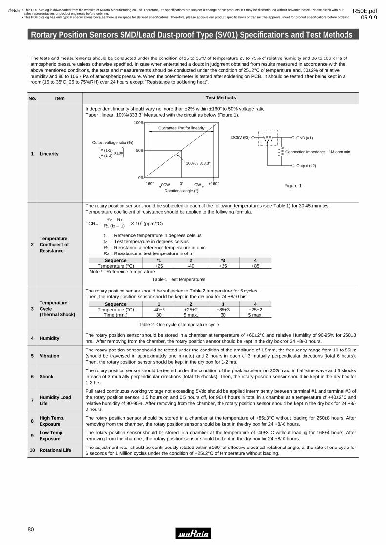
No. Item Test Methods
Independent linearity should vary no more than ±2% within ±160° to 50% voltage ratio.Taper : linear, 100%/333.3° Measured with the circuit as below (Figure 1).
Linearity1
The rotary position sensor should be subjected to each of the following temperatures (see Table 1) for 30-45 minutes.Temperature coefficient of resistance should be applied to the following formula.
TCR= Z 106 (ppm/°C)
t1 : Reference temperature in degrees celsiust2 : Test temperature in degrees celsiusR1 : Resistance at reference temperature in ohmR2 : Resistance at test temperature in ohm
Note * : Reference temperature
R2 – R1
R1 (t2 – t1)
TemperatureCoefficient ofResistance
2
Guarantee limit for linearity100%
50%
100% / 333.3°
-160° 0° +160°0%
CCW CW
Rotational angle (°)
Output voltage ratio (%)
V (1-2)V (1-3)
X100
GND (#1)
Connection Impedance : 1M ohm min.
DC5V (#3)
Output (#2)
Figure-1
SequenceTemperature (°C) +25
*1-402
+25*3
+854
The rotary position sensor should be subjected to Table 2 temperature for 5 cycles.Then, the rotary position sensor should be kept in the dry box for 24 +8/-0 hrs.
TemperatureCycle(Thermal Shock)
3
The rotary position sensor should be stored in a chamber at temperature of +60±2°C and relative Humidity of 90-95% for 250±8hrs. After removing from the chamber, the rotary position sensor should be kept in the dry box for 24 +8/-0 hours.
Humidity4
The rotary position sensor should be tested under the condition of the amplitude of 1.5mm, the frequency range from 10 to 55Hz(should be traversed in approximately one minute) and 2 hours in each of 3 mutually perpendicular directions (total 6 hours).Then, the rotary position sensor should be kept in the dry box for 1-2 hrs.
Vibration5
The rotary position sensor should be tested under the condition of the peak acceleration 20G max. in half-sine wave and 5 shocksin each of 3 mutually perpendicular directions (total 15 shocks). Then, the rotary position sensor should be kept in the dry box for1-2 hrs.
Shock6
Full rated continuous working voltage not exceeding 5Vdc should be applied intermittently between terminal #1 and terminal #3 ofthe rotary position sensor, 1.5 hours on and 0.5 hours off, for 96±4 hours in total in a chamber at a temperature of +40±2°C andrelative humidity of 90-95%. After removing from the chamber, the rotary position sensor should be kept in the dry box for 24 +8/-0 hours.
Humidity LoadLife
7
The rotary position sensor should be stored in a chamber at the temperature of +85±3°C without loading for 250±8 hours. Afterremoving from the chamber, the rotary position sensor should be kept in the dry box for 24 +8/-0 hours.
High Temp.Exposure
8
The rotary position sensor should be stored in a chamber at the temperature of -40±3°C without loading for 168±4 hours. Afterremoving from the chamber, the rotary position sensor should be kept in the dry box for 24 +8/-0 hours.
Low Temp.Exposure
9
The adjustment rotor should be continuously rotated within ±160° of effective electrical rotational angle, at the rate of one cycle for6 seconds for 1 Million cycles under the condition of +25±2°C of temperature without loading.
Rotational Life10
SequenceTemperature (°C)
Time (min.)-40±3
30
1+25±25 max.
2+85±3
30
3+25±25 max.
4
Table-1 Test temperatures
Table 2: One cycle of temperature cycle
The tests and measurements should be conducted under the condition of 15 to 35°C of temperature 25 to 75% of relative humidity and 86 to 106 k Pa ofatmospheric pressure unless otherwise specified. In case when entertained a doubt in judgment obtained from results measured in accordance with theabove mentioned conditions, the tests and measurements should be conducted under the condition of 25±2°C of temperature and, 50±2% of relative humidity and 86 to 106 k Pa of atmospheric pressure. When the potentiometer is tested after soldering on PCB., it should be tested after being kept in aroom (15 to 35°C, 25 to 75%RH) over 24 hours except "Resistance to soldering heat".
Rortary Position Sensors SMD/Lead Dust-proof Type (SV01) Specifications and Test Methods
80
9
!Note • Please read rating and !CAUTION (for storage, operating, rating, soldering, mounting and handling) in this catalog to prevent smoking and/or burning, etc.• This catalog has only typical specifications because there is no space for detailed specifications. Therefore, please approve our product specifications or transact the approval sheet for product specifications before ordering.
• This PDF catalog is downloaded from the website of Murata Manufacturing co., ltd. Therefore, it’s specifications are subject to change or our products in it may be discontinued without advance notice. Please check with our sales representatives or product engineers before ordering.
• This PDF catalog has only typical specifications because there is no space for detailed specifications. Therefore, please approve our product specifications or transact the approval sheet for product specifications before ordering.
!Note R50E.pdf05.9.9

Rortary Position Sensors Connector Dust-proof Type (SV21) Specifications and Test Methods
81
9
!Note • Please read rating and !CAUTION (for storage, operating, rating, soldering, mounting and handling) in this catalog to prevent smoking and/or burning, etc.• This catalog has only typical specifications because there is no space for detailed specifications. Therefore, please approve our product specifications or transact the approval sheet for product specifications before ordering.
No. Item Test Methods
1 Linearity
Rotational life
Temperaturecharacteristics
Shock
Vibration
2
3
4
5
Linearity is specified the following maximum deviation (C) as percentage of the output voltage (E) from the output voltage approximate straight-line (Y) in FS (full scale) within the electrical effective rotational angle. (Linearity = C/FS x 100%)Approximate straight-line (Y=mθ+b) is calculated by least square from measured output voltage curve.FS is specified the range from min. output voltage (Y min.) to max. output voltage (Y max.) of approximate straight-line within the electrical effective rotational angle.
Y= Approximate straight-line of output voltage (V)θ= Rotational angle (°)C= Maximum deviation of output voltage (E1) from output voltage approximate straight-line (Y1)
Temperature characteristics is specified as percentage the maximum deviation of output voltage from that at 25±2°C in FS (full scale).
The adjustment rotor should be continuously rotated within ±100° of effective electrical rotational angle, at the rate of one cycle for 1 seconds for 10 Million cycles under the condition of 25±2°C of temperature without loading.
The rotary position sensor should be tested under the condition of the amplitude of 1.5mm, the frequency range from 10 to 55Hz (should be traversed in approximately one minute) and 2 hours in each of 3 mutually perpendicular directions (total 6 hours).
The rotary position sensor should be tested under the condition of the peak acceleration 100G max. in half-sine wave and 4 shocks in each of 3 mutually perpendicular directions (total 12 shocks).
Electrical Effective Rotaitional Angle
Rotaitional Angle θ
0°
Out
put V
olta
ge E
E1(V)
Y1(V)
Y max.
FS
Y min.
Y=mX+b
C
• This PDF catalog is downloaded from the website of Murata Manufacturing co., ltd. Therefore, it’s specifications are subject to change or our products in it may be discontinued without advance notice. Please check with our sales representatives or product engineers before ordering.
• This PDF catalog has only typical specifications because there is no space for detailed specifications. Therefore, please approve our product specifications or transact the approval sheet for product specifications before ordering.
!Note R50E.pdf05.9.9

Packaging
82
9
!Note • Please read rating and !CAUTION (for storage, operating, rating, soldering, mounting and handling) in this catalog to prevent smoking and/or burning, etc.• This catalog has only typical specifications because there is no space for detailed specifications. Therefore, please approve our product specifications or transact the approval sheet for product specifications before ordering.
Minimum Quantity
Part NumberMinimum Quantity (pcs.)
PVZ2A
PVZ2K/R
PVA2
PVZ3A
PVZ3K/R
PVS3
PVA3
PVG3A/G
PVG3K
PVM4
PVF2A
PVG5A
PVG5H
PV01W/P/X
PVC6A/D/G/H/E
PVC6M/Q
PV34
PV32
PV23/12
PV22
PV36W
PV36Y
PV36X
PV36Z/P
PV37Y/Z
PV37W/X/P
SV01A
SV01L
SV21
3000
3000
3000
2000
1500
2500
2000
1000
500
500
500
250
500
—
—
—
—
—
—
—
—
—
—
—
—
—
—
—
—
ø180mm reel
12000
—
—
8000
—
8000
8000
—
—
3000
—
—
—
—
—
—
—
—
—
—
—
—
—
—
—
—
1000
—
—
ø330mm reel
—
—
—
—
—
—
—
—
—
—
—
—
—
—
—
1000
—
—
—
—
1000
—
1000
—
1000
—
—
—
—
Ammo Pack
—
—
—
—
—
—
—
—
—
—
—
—
—
50
50
50
—
—
—
—
50
50
40
40
—
—
—
—
—
Magazine
1000
1000
1000
1000
1000
1000
1000
500
—
500
100
50
50
—
50
50
100
100
50
30
50
50
50
50
50
50
50
—
10
Bulk
—
—
—
—
—
—
—
—
—
—
—
—
—
—
—
—
—
—
—
—
—
—
—
—
—
—
—
1000
—
Tray
Dimensions of ReelPVZ2A/PVA2/PVZ3A/PVS3/PVA3/PVF2
(in mm)
13.0±0.5 dia.
21.0±0.8 dia.
2.0±0.5
178±2 dia.
9.0±1.0
50 m
in.
13.0±1.0
PVZ2K/PVZ2R/PVZ3K/PVZ3R/PVM4/PVG3/PVG5H
(in mm)
13.0±0.5 dia.
21.0±0.8 dia.
2.0±0.5
178±2 dia.
13.0±1.0
50 m
in.
17.0±1.0
Continued on the following page.
• This PDF catalog is downloaded from the website of Murata Manufacturing co., ltd. Therefore, it’s specifications are subject to change or our products in it may be discontinued without advance notice. Please check with our sales representatives or product engineers before ordering.
• This PDF catalog has only typical specifications because there is no space for detailed specifications. Therefore, please approve our product specifications or transact the approval sheet for product specifications before ordering.
!Note R50E.pdf05.9.9

Packaging
83
9
!Note • Please read rating and !CAUTION (for storage, operating, rating, soldering, mounting and handling) in this catalog to prevent smoking and/or burning, etc.• This catalog has only typical specifications because there is no space for detailed specifications. Therefore, please approve our product specifications or transact the approval sheet for product specifications before ordering.
Continued from the preceding page.
Dimensions of ReelPVG5A
(in mm)
21.0±0.8 Dia.
50 D
ia. m
in.
178.0±2.0 Dia.
13.0±0.5 Dia.
2.0±0.5
17.0±1.0
19.4±1.0
SV01
(in mm)
13.0±0.5 dia.
21.0±0.8 dia.
2.0±0.5
330±2 dia.
25.5±1.0
80±1
dia
.
29.5±1.0
Dimensions of Plastic Tape
Part Number
PVZ2A
PVZ2K
PVZ2R
PVA2
PVZ3A/PVA3
PVZ3K
PVZ3R
PVS3
PVF2
2.4±0.2
3.3±0.2
2.3±0.2
(in mm)
A
3.1±0.1
5.7±0.2
5.1±0.2
3.1±0.1
3.8±0.2
5.8±0.2
6.5±0.2
4.1±0.2
2.3±0.2
B
8.0±0.2
12.0±0.2
8.0±0.2
12.0±0.2
8.0±0.2
C
3.5±0.1
5.5±0.1
3.5±0.1
5.5±0.1
3.5±0.1
D
1.1±0.1
1.0±0.1
1.1±0.1
1.95±0.1
2.3±0.1
2.1±0.1
1.6±0.1
2.3±0.1
I
0.2±0.1
0.3±0.1
0.2±0.1
0.3±0.1
0.2±0.1
0.3±0.1
J
a
a'
4.0±0.1
2.0±0.1
4.0±0.11.5 dia.+0.1
–0
1.75±0.1
D C
A
B
J
I
Across a – a'
Tape feeding direction
• The side containing terminals #1 and #3 faces the plastic tape pilot holes.
PVZ2 / PVA2 / PVZ3 / PVA3 / PVS3 / PVF2
Continued on the following page.
• This PDF catalog is downloaded from the website of Murata Manufacturing co., ltd. Therefore, it’s specifications are subject to change or our products in it may be discontinued without advance notice. Please check with our sales representatives or product engineers before ordering.
• This PDF catalog has only typical specifications because there is no space for detailed specifications. Therefore, please approve our product specifications or transact the approval sheet for product specifications before ordering.
!Note R50E.pdf05.9.9

Packaging
84
9
!Note • Please read rating and !CAUTION (for storage, operating, rating, soldering, mounting and handling) in this catalog to prevent smoking and/or burning, etc.• This catalog has only typical specifications because there is no space for detailed specifications. Therefore, please approve our product specifications or transact the approval sheet for product specifications before ordering.
Continued from the preceding page.
Dimensions of Plastic Tape
Part Number
PVG3A
PVG3G
PVM4
PVG5H
4.0±0.1
4.5±0.2
5.4±0.2
A
4.0±0.1
4.9±0.1
5.5±0.2
5.8±0.2
B
2.1±0.1
2.15±0.1
4.0±0.1
I
0.3±0.1
0.3±0.1
0.4±0.1
J
(in mm)
• The side containing terminals #1 and #3 faces the plastic tape pilot holes
(except PVG3).
PVG3A / PVG3G / PVM4 / PVG5H
J
I
Across a – a'
12.0
±0.2
5.5±
0.1
1.75
±0.1
2.0±0.1
8.0±0.1a
B
A
Tape feeding direction
a'
4.0±0.1 1.5 dia.+0.1–0
Part Number
PVG5A 4.3±0.2
A
5.4±0.2
B
5.4±0.1
I
0.4±0.1
J
(in mm)
PVG5A
J
I
Across a – a'
16.0
±0.3
7.5±
0.1
1.75
±0.1
Tape feeding direction
2.0±0.1
12.0±0.2a
B
Aa'
4.0±0.1 1.5 dia.+0.1–0
Continued on the following page.
• This PDF catalog is downloaded from the website of Murata Manufacturing co., ltd. Therefore, it’s specifications are subject to change or our products in it may be discontinued without advance notice. Please check with our sales representatives or product engineers before ordering.
• This PDF catalog has only typical specifications because there is no space for detailed specifications. Therefore, please approve our product specifications or transact the approval sheet for product specifications before ordering.
!Note R50E.pdf05.9.9

Packaging
85
9
!Note • Please read rating and !CAUTION (for storage, operating, rating, soldering, mounting and handling) in this catalog to prevent smoking and/or burning, etc.• This catalog has only typical specifications because there is no space for detailed specifications. Therefore, please approve our product specifications or transact the approval sheet for product specifications before ordering.
Continued from the preceding page.
Dimensions of Plastic TapePVG3K
(in mm)
4.0±0.1
2.8±0.14.0±0.1
2.0±0.1 0.3±0.1
8.0±0.1
1.5 dia.+0.1-0
12.0
±0.2
6.2±
0.1
5.5±
0.1
1.75
±0.1
0
Tape feeding direction
Across a-a'
a
a'
SV01
a2.0±0.05
a'
Tape feeding direction
4.0
16.0
11.4
11.5
24.0
16.3
1.75
Across a-a'
0.4±0.05
3.5
1.5 -0 Dia.+0.1
Tolerance: ±0.1in mm( )
Dimensions of Radial TapingPVC6M
0±2
6.35±0.70
12.7±0.3
#2
#3 #1
2.5 2.5
4.0±0.1 Dia.
#1 #2 #3
5.2
6.9
A A'
B B'
12.7±1.0
0.5±
0.2
Across A-A'
Across B-B'
6.0
min
.
9.0±
0.5
18.0
±0.5
3-0.5 Dia.
6.9
0.55W×3.2L×1.3D
3.2 Dia.
Tolerance : ±0.3 ( in mm)
2.5±0.5 2.5±0.518.5
- 0.
5+
1.0
PVC6Q
8.0
3.25
A A'
B'B
2.5±0.52.5±0.5
0±2
6.35±0.70
12.7±0.34.0±0.1 Dia.
#1 #2 #3
18.5
- 0.
5+
1.0
12.7±1.0
0.5±
0.2
Across A-A'
Across B-B'6.0
min
.
9.0±
0.5
18.0
±0.5
3-0.5 Dia.
6.9
0.55W×3.2L×1.3D
3.2 Dia.
Tolerance : ±0.3 ( in mm)
PV37Y12.7±1.0
0±2.06.4
6.7
2.5±0.5
12.7±0.36.35±0.70
3−0.4±0.1 Dia
18.0
±0.5
9.0±
0.5
2.5±0.5
0.5±
0.2
Across A-A'
A A'
Tolerance : ±0.3 ( in mm)
18.5
- 0.
5+
1.0
4.0±0.1 Dia.
B B'
#3#2#16.0
min
.
Across B-B'
2.52.5
2.0
4.0
PV37Z12.7±1.0
0±2.06.4
6.7
2.5±0.5
12.7±0.36.35±0.70
3–0.4±0.1 Dia
18.0
±0.5
9.0±
0.5
2.5±0.5
0.5±
0.2
Across A-A'
A A'
Tolerance : ±0.3 ( in mm)
18.5
- 0.
5+
1.0
4.0±0.1 Dia.
B B'
#3#2#16.0
min
.
Across B-B'
2.0
2.52.5
4.0
Continued on the following page.
• This PDF catalog is downloaded from the website of Murata Manufacturing co., ltd. Therefore, it’s specifications are subject to change or our products in it may be discontinued without advance notice. Please check with our sales representatives or product engineers before ordering.
• This PDF catalog has only typical specifications because there is no space for detailed specifications. Therefore, please approve our product specifications or transact the approval sheet for product specifications before ordering.
!Note R50E.pdf05.9.9

Packaging
86
9
!Note • Please read rating and !CAUTION (for storage, operating, rating, soldering, mounting and handling) in this catalog to prevent smoking and/or burning, etc.• This catalog has only typical specifications because there is no space for detailed specifications. Therefore, please approve our product specifications or transact the approval sheet for product specifications before ordering.
Continued from the preceding page.
Dimensions of Radial TapingPV36W
18.5
- 0.
5+
1.0
12.7±1.00±2.09.6
10.0
2.5±0.5
12.7±0.36.35±0.70
3–0.5±0.1 Dia
18.0
±0.5
9.0±
0.5
2.5±0.5
0.5±
0.2
Across A-A'
A A'
Tolerance : ±0.3 ( in mm)
4.0±0.1 Dia.
B B'
#3#2#16.0
min
.
Across B-B' 2.5
2.52.5
PV36X12.7±1.0
0±2.09.6
10.0
2.5±0.5
12.7±0.36.35±0.70
3–0.5±0.1 Dia
18.0
±0.5
9.0±
0.5
2.5±0.5
0.5±
0.2
Across A-A'
A A'
6.0
min
.
Tolerance : ±0.3 ( in mm)
18.5
- 0.
5+
1.0
4.0±0.1 Dia.
#3 #2 #1
B B'
Across B-B' 2.5
2.52.5
Dimensions of Ammo Pack
3T
1T330 max.46 m
ax.
305
max
.
(in mm)
Dimensions of Magazine Packaging
9.8±0.5
15.3
±0.5
9.0±0.5
18.8
±0.5
370 +0–1.0
(in mm)
PV01 PVC6
7.3±0.5
21.1
±0.5
508 +0–1.0 11.5±0.5
18.0
±0.5
508 +0–1.0
PV36W/Y/X/Z PV36P
413 +0–1.0
• This PDF catalog is downloaded from the website of Murata Manufacturing co., ltd. Therefore, it’s specifications are subject to change or our products in it may be discontinued without advance notice. Please check with our sales representatives or product engineers before ordering.
• This PDF catalog has only typical specifications because there is no space for detailed specifications. Therefore, please approve our product specifications or transact the approval sheet for product specifications before ordering.
!Note R50E.pdf05.9.9

Recommended Adjustment Tools/Qualified Standards
87
9
!Note • Please read rating and !CAUTION (for storage, operating, rating, soldering, mounting and handling) in this catalog to prevent smoking and/or burning, etc.• This catalog has only typical specifications because there is no space for detailed specifications. Therefore, please approve our product specifications or transact the approval sheet for product specifications before ordering.
Recommended Adjustment Tools
PVZ2/PVA2
PVZ3/PVA3
PVS3
PVG3
PVM4
PVG5
PVC6
others
MURATA MFG.
VESSEL MFG.
TORAY INDUSTRIES, INC.
TORAY INDUSTRIES, INC.
TORAY INDUSTRIES, INC.
VESSEL MFG.
VESSEL MFG.
ENGINEER INC.
VESSEL MFG.
TORAY INDUSTRIES, INC.
VESSEL MFG.
ENGINEER INC.
ManufacturersTrimmer Potentiometer Series
KMDR190
No.9000+1.7Z30
SA-2225
SA-2225
SA-2225
No.9000–2.6Z30
No.9000–1.3Z30
DA-54
No.9000+0Z30
SA-2225
No.9000–1.8Z30
DA-40
DA-55
Model Number
KMDR190
KMDR080
KMDR070
KMDR070
KMDR070
KMDR120
KMDR130
KMDR150
KMDR070
KMDR110
KMDR180
MURATA Model Number
+ Cross
+ Cross
– Minus (round edge)
– Minus (round edge)
– Minus (round edge)
– Minus
– Minus
– Minus
+ Cross
– Minus (round edge)
– Minus
– Minus (both ends)
– Minus
Blade
Trimmer Potentiometer Series
PVC6
PVZ3PVA3PVS3PVG3
TORAY INDUSTRIES, INC.
VESSEL MFG.
TORAY INDUSTRIES, INC.
Manufacturers
JB-2225
No.CA-10
JB-2225
Model Number
KMBT070
KMBT090
KMBT070
MURATA Model Number
– Minus (round edge)
+ Cross
– Minus (round edge)
Blade
For Automatic Adjustment
Qualified Standards
MURATA FACTORY
Sabae Murata Mfg.Co.,Ltd.
Qualified Date
August 14, 1997
Standard
UNDERWRITERS LABORATORIES INC.
Qualified Number
A5704
Wuxi Murata Electronis Co.,Ltd. May 12, 1999 UNDERWRITERS LABORATORIES INC. A7924
The products listed here have been produced by the ISO9001 and ISO/TS16949 certified factory.
∗ No ODCs (Ozone Depleting Chemicals) are used on all Murata's trimmer potentiometers.
• This PDF catalog is downloaded from the website of Murata Manufacturing co., ltd. Therefore, it’s specifications are subject to change or our products in it may be discontinued without advance notice. Please check with our sales representatives or product engineers before ordering.
• This PDF catalog has only typical specifications because there is no space for detailed specifications. Therefore, please approve our product specifications or transact the approval sheet for product specifications before ordering.
!Note R50E.pdf05.9.9

Note:1. Export Control
<For customers outside Japan>No muRata products should be used or sold, through any channels, for use in the design, development, production, utilization, maintenance or operation of, orotherwise contribution to (1) any weapons (Weapons of Mass Destruction (nuclear, chemical or biological weapons or missiles) or conventional weapons) or (2)goods or systems specially designed or intended for military end-use or utilization by military end-users.<For customers in Japan>For products which are controlled items subject to the “Foreign Exchange and Foreign Trade Law” of Japan, the export license specified by the law is requiredfor export.
2. Please contact our sales representatives or product engineers before using the products in this catalog for the applications listed below, which require especiallyhigh reliability for the prevention of defects which might directly damage a third party's life, body or property, or when one of our products is intended for use inapplications other than those specified in this catalog.q Aircraft equipment w Aerospace equipmente Undersea equipment r Power plant equipmentt Medical equipment y Transportation equipment (vehicles, trains, ships, etc.)u Traffic signal equipment i Disaster prevention / crime prevention equipmento Data-processing equipment !0 Application of similar complexity and/or reliability requirements to the applications listed above
3. Product specifications in this catalog are as of May 2005. They are subject to change or our products in it may be discontinued without advance notice. Pleasecheck with our sales representatives or product engineers before ordering. If there are any questions, please contact our sales representatives or productengineers.
4. Please read rating and CAUTION (for storage, operating, rating, soldering, mounting and handling) in this catalog to prevent smoking and/or burning, etc.
5. This catalog has only typical specifications because there is no space for detailed specifications. Therefore, please approve our product specifications ortransact the approval sheet for product specifications before ordering.
6. Please note that unless otherwise specified, we shall assume no responsibility whatsoever for any conflict or dispute that may occur in connection with the effectof our and/or a third party's intellectual property rights and other related rights in consideration of your use of our products and/or information described orcontained in our catalogs. In this connection, no representation shall be made to the effect that any third parties are authorized to use the rights mentionedabove under licenses without our consent.
7. No ozone depleting substances (ODS) under the Montreal Protocol are used in our manufacturing process.
International Division3-29-12, Shibuya, Shibuya-ku, Tokyo 150-0002, Japan Phone: 81-3-5469-6123 Fax: 81-3-5469-6155 E-mail: [email protected]
Head Office1-10-1, Higashi Kotari, Nagaokakyo-shi, Kyoto 617-8555, JapanPhone: 81-75-951-9111
http://www.murata.com/
• This PDF catalog is downloaded from the website of Murata Manufacturing co., ltd. Therefore, it’s specifications are subject to change or our products in it may be discontinued without advance notice. Please check with our sales representatives or product engineers before ordering.
• This PDF catalog has only typical specifications because there is no space for detailed specifications. Therefore, please approve our product specifications or transact the approval sheet for product specifications before ordering.
!Note R50E.pdf05.9.9