Embed Size (px)
Citation preview
International Journal of Solids and Structures 59 (2015) 46–57
Contents lists available at ScienceDirect
International Journal of Solids and Structures
journal homepage: www.elsevier .com/locate / i jsolst r
Multistable grid and honeycomb shells
http://dx.doi.org/10.1016/j.ijsolstr.2015.01.0020020-7683/� 2015 Elsevier Ltd. All rights reserved.
⇑ Corresponding author.E-mail addresses: [email protected] (E.G. Loukaides), [email protected]
(K.A. Seffen).
E.G. Loukaides, K.A. Seffen ⇑Department of Engineering, University of Cambridge, Trumpington Street, Cambridge CB2 1PZ, UK
a r t i c l e i n f o
Article history:Received 3 September 2014Received in revised form 17 December 2014Available online 10 January 2015
Keywords:MultistableShellGridHoneycombComposite
a b s t r a c t
The manufacturing of multistable shells has been dominated by the use of pre-stressed and compositematerials. Here we advocate the use of common materials through a simple design that requires nopre-stressing and has an initially developable geometry. A rudimentary demonstrator is constructedand serves as the starting point for further study. An existing homogenisation model for a lattice struc-ture is combined with an analytical strain energy model from the literature to show the mechanical prop-erties needed to construct an initially developable, bistable grid shell. The concept is also tested in acommercial finite element package, where a number of parametric studies are performed. Both the dem-onstrator and the FE model confirm the validity of the design while a series of parametric studies helpsestablish the limits of this behaviour with respect to local and global geometry of grid shell and honey-comb structures.
� 2015 Elsevier Ltd. All rights reserved.
1. Introduction
This work addresses the challenge of designing initially devel-opable, free-standing, multistable shells without the use of com-posite materials or pre-stressing. Multistable shells have beenthe focus of much recent work since they offer a basis for the con-struction of morphing structures. They are able to support loads indistinct geometries, without the need for elaborate mechanisms.The manufacturing of multistable shells has been dominated bythe use of pre-stressed materials and fibre-reinforced composites;in retrospect, this can be attributed to the work by Hyer (1981),which introduced unsymmetric laminates as viable candidatesfor engineering applications of bistable shells. Laminates areattractive because they offer control of material properties throughthe orienting of the distinct laminae. However, laminates also havea number of disadvantages, namely, they are relatively expensiveand they require skilled manual assembly and dedicated facilities.Perhaps most importantly, they are harder to employ in continu-ous large-scale (in the order of tens of metres and above) andsmall-scale (in the order of millimetres and below) structures.
At the same time, there has been a surge in the development of‘‘smart materials,’’ which often provide the basis for morphingstructural applications. These can be expensive, offer highly spec-ialised properties, and often are not straightforward to integratewithin the host structure; hence, there is clear motivation to find
alternative ways of controlling material properties. One attractiveapproach is to use the local geometry of a material; with suchmethods we can lower our dependence on more expensive andoften harder-to-manufacture composite materials. Some ways ofmanipulating the macro-mechanical properties of shells throughpatterning and texturing have been studied previously in this con-text. Recent examples of such concepts exist in the form of corru-gated shells (Norman et al., 2008; Norman et al., 2009) anddimpled sheets (Golabchi and Guest, 2009).
Although these methods have their respective motivations andapplications, here we seek as simple a technique as possible, tomake manufacturing straightforward and scalable. Taking inspira-tion from earlier laminate designs, we note that the major stiffnesscontribution comes from the fibres; the matrix mostly serves as abinder for those more essential structural components. Similarproperties can be obtained if we removed material from a solidplate of an isotropic material, in such a way that reproduces thestiffening action of the fibres along particular directions. The crea-tion of perforations is both a simple procedure and an easily scal-able one. This concept corresponds to grid shells, honeycombs andperforated shells, whose global material properties can be manip-ulated by variations in the local geometry. The correspondencebetween the mechanical properties of long fibre composites andgridshells is widely known, but the particular conditions thatwould enable multistability in gridshells have not been examinedbefore.
The theoretical treatment of multistable shells has most com-monly employed the Uniform Curvature (UC) assumption, firstused by Mansfield (1962). By considering ‘‘lenticular’’ sections,

E.G. Loukaides, K.A. Seffen / International Journal of Solids and Structures 59 (2015) 46–57 47
where the bending moment naturally diminishes at the periphery,he produced exact solutions of the Föppl–Von Kármán equations.The same author later justified the obvious weakness of the modelto describe a known variation of the curvature at the boundarylayer when constant thickness shells are considered. In Mansfield(2005), the approximate width of the boundary layer is calculatedfor an initially flat strip, thickness t, bent to a curvature j along itslength by end moments applied to its ends. The resulting width of0:77
ffiffiffiffiffiffiffiffit=j
pis very small for thin shells in large-deflection scenarios.
Hyer (1981) produced an even simpler model, using the sameUC assumption, and discretising the FVK equations with the Ray-leigh–Ritz method. The simplicity of this model proved powerfulin many instances and was used in various studies, especially relat-ing to composite plates under thermal loads (Salamon and Masters,1995; Dano and Hyer, 1998). At the same time, deficiencies of theUC assumption were noted, for example, Gigliotti et al. (2004)point out that the importance of planform aspect ratio is missedby both models. The failure of the UC assumption to exactly cap-ture the boundary condition was mentioned above and led to var-ious efforts to construct models with many more degrees offreedom (Aimmanee and Hyer, 2004; Pirrera et al., 2012). Thisappears to be so when stretching effects dominate behaviour, forexample, when the shell has initial Gaussian curvature. Coburnet al. (2013) show that the deformed shapes of spherical caps haveboundary layers wider than Mansfield’s approximation — becausethey possess significant Gaussian curvature, which can only becaptured accurately using higher-order curvature distributions.Our initial and deformed shapes of shell are close to being develop-able throughout: stretching (and boundary layer) effects are mini-mal, which enables us to proceed with a uniform curvatureassumption.
Bistable, developable shells are not new. In the context ofMEMS, for example, we have various examples (Gerson et al.,2012; Pham and Wang, 2011). These, however, contain the well-known clamped, bistable arch and effectively rely on initiallyloaded boundaries for bistability to proceed. The shells presentedhere are unloaded and only restrained at one central point to pre-vent rigid body motion.
A set of workers persisted in extending the Mansfield model,especially in association with multistable shells, producing variouspractical results along the way. Guest and Pellegrino (2006)focused on a developable formulation that described bistable cylin-drical shells, where bistability depends on the modular ratiobetween different orientations of the structure; Seffen (2007),accounting for both bending and stretching effects, showed thatmultistability is possible even for isotropic, pre-stressed shells;Vidoli and Maurini (2008) extended the scope of the examinationby Seffen to describe the feasibility of a shallow, tristable, orthotro-pic shell; Fernandes et al. (2010), again with the same formulation,gave a method of quasi-statically actuating a bistable, pre-stressedshell. The analytical model used in the present work — an exten-sion of the work in Seffen (2007) — clearly falls within this tradi-tion, and the corresponding symbols are employed whereappropriate.
The aim of the present study is to prove that grid shells andhoneycomb shells can be made to be (at the very least) bistablewhen initially free of stresses and singly curved. Both types of shellare connected networks of beam-like elements, but their elasticresponses differ because of relative differences in their local geo-metrical proportions. The cross-section of grid shell beams typi-cally have comparable width and depth and thus, they respondlocally as classical Euler–Bernoulli, or Timoshenko, beams. Honey-comb beams have a depth-to-width ratio greater than ten, andbehave as slender webs, which are more prone to local distortionsand instabilities when bending and torsion are locally applied; fun-damentally, the Euler–Bernoulli hypothesis that cross-sectional
shape remains conserved, is not guaranteed, and the beams haveto be treated as plate-like elements aligned to the through-thick-ness direction (Cote et al., 2004; Russell et al., 2011). On the otherhand, the elastic response of perforated plates, which are formedby drilling, or stamping out, holes in a thin homogenous plate,under simple in-plane loads can be found exactly by making useof the well-known solution for the stress-field around a hole(Slot and O’Donnell, 1971). This response is then cast as the setof effective orthotropic properties, offered by an equivalent uni-form plate without holes.
We address the feasibility of grid and honeycomb shells asbistable candidates by reversing the homogenisation process inthe context of the previous well-known models of multistability:these models reveal the required range of effective orthotropicproperties and initial uniform curvatures of the shell mid-surface.We assume from the outset that the effective properties of ourshells do not depend on the initial uniform curvatures: so thathomogenisation considers a flat shell, for simplicity and thus, wemay decouple the realisation of the global geometry from the siz-ing of the local beam elements. The latter is aided by well-estab-lished homogenisation models for grid and honeycomb shells,which in their majority, however, only deal with in-plane loading.Converting these results into out-of-plane bending and twistingmoduli for each type of shell usually follows the practice by whichthe so-called ABD matrices are obtained, by summing and integrat-ing effects though the thickness (Mansfield, 2005). Here, this isappropriate when the local behaviour is beam-like, as in gridshells, because integration assumes implicitly that the cross-sec-tional shape is conserved. To our knowledge, this has not beentested for the deeper local beams in honeycomb shells, so we usethe same process but treat the results with caution. In order to testand confirm our results, we resort to a complementary finite ele-ment analysis of both shells.
Section 2 presents a physical demonstrator constructed in thelaboratory, which acts as motivation for the investigation that fol-lows. Both grid shells and honeycomb shells can be defined by thesame geometrical terms, which are introduced in Section 3. Theoverall geometry is dictated by the planform outline, its size andits initial curvature. Locally, the beam network is a symmetricalsquare mesh made up of interconnected prismatic sections gov-erned by their length, width and height (or depth). Both sets ofproperties are hierarchically related in the relative senses of mag-nitude and orientation: the density of the grid network must behigh enough for homogenisation to be effective in practical terms,and we describe the orientation by the angles between the localbeam directions, the global axis of initial curvature and the globaledges of shell. From the outset, we stipulate globally symmetricallayouts, in order to reduce the number of independent parameters,and we focus on effective material properties for two such orienta-tions. These are chosen to avoid anisotropic coupling for furthersimplicity, and the generalised Hooke’s laws in extension andbending are expressed via the usual A and D matrices for orthotro-pic materials.
Using the earlier UC model (Section 4), we then show that mul-tistability is concomitant to the effective torsional rigidity, a, andPoisson’s ratio, m, alone in the original dimensionless framework,with both taking values as large as possible. Their expressionsare calculated from the Hooke’s laws explicitly in terms of theratios of the local geometrical parameters: we also calculate thestability landscape in terms of a range of values for each parameter,in order to identify the relative requirements between them forachieving bistability.
We then establish the set of geometrical parameters for ourfinite element ‘‘starting’’ model in Section 5, where we first focuson grid shells: we describe mesh generation, the choice ofelements, the boundary conditions, solution control and how to

48 E.G. Loukaides, K.A. Seffen / International Journal of Solids and Structures 59 (2015) 46–57
establish multistable behaviour from the simulations. We also con-sider the sensitivity of performance to element density and we dis-cuss the deviations in deformed equilibrium shape compared tothe UC model assumptions. Parametric studies on bistability arethen carried out by varying the initial radius of curvature and theheight-to-width ratio of constituent beam elements. The latterframes further study on the effective depth of the grid shell, wheredeeper shells are considered to be honeycomb shells but whichmust be constituted of shell elements for accurate computationalassessment. A parametric study follows, but not at the same levelof detail as before for the sake of brevity. Out of interest, we showthat a helically-curved honeycomb shell can also be bistable beforeconcluding with a summary of our findings.
2. Physical demonstrator
The design and construction of a hand-held physical model waspursued, where the planform dimensions are in the order of deci-metres. In terms of material, any isotropic material satisfies themechanical properties. However, the large deformations involvedin travelling from one stable state to the next need to be consid-ered. An intermediate flat state helps establish an upper ceilingfor the required strains. For example, let us consider a cylindricalshell with a square a� a planform, a thickness h and initial curva-ture radius of curvature qi. Considering a known symmetry forbistable cylindrical shells during the transition to a secondary state(Guest and Pellegrino, 2006), the originally curved direction of theshell ends up in an almost flat configuration. Hence an estimate forthe strain upper limit of the extreme fibres is given by:
� ¼ h2qi
ð1Þ
For h ¼ 10 mm and qi ¼ 160 mm, values of practical concern here,� � 3%, which is greater than typical maximum strains for metals;hence, we need to consider alternative materials. Thermoplastics fitthe strain requirement; they can withstand strains above 10%before yielding, depending on the type of the plastic (Biron,2012). In addition, they can be easily cut and drilled. Finally, theycan be bent and shaped at a low temperature — the so-called crys-talline melting point — below 200 �C in some cases (Tripathi, 2002).If the material goes beyond this temperature, deforms and thencools to below its recrystallisation temperature, it retains itsdeformed shape.
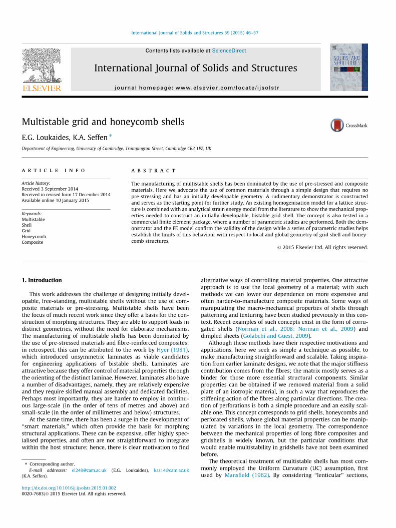
Fig. 1. A honeycomb structure carved out of a solid polypropylene sheet using a water-jeare 300 mm� 300 mm. The unit cell has a length of 10 mm while the ligament cross-sectoperation, and results in a few imperfections, seen more clearly on the right.
A demonstrator is constructed out of a 6 mm sheet of the ther-moplastic polypropylene (PP), which is cheap and widely available.A water-jet cutter is used to shape the desired local geometry,starting with a 300 mm� 300 mm square. The side-length of unitcell — the ‘‘ligament’’ length, is 10 mm, and the target ligamentthickness is 0.1 mm, which is very thin and leads to a few imper-fections as seen in Fig. 1. The sample is then constrained by a cylin-drical mould with a radius of 160 mm and heated to a temperatureof 160�.
After cooling the sample to room temperature and removing themould, we observe a spring-back effect — the demonstrator doesnot lose all residual stress during heating — but it remains cylindri-cally curved. There is also some local buckling of ligaments, sincethe sample was constrained to bend in the mould at room temper-ature. Nevertheless, bistable behaviour is ascertained as docu-mented in Fig. 2. The second state is almost cylindrical, with asmaller curvature orthogonal to the initial curvature but directedout-of-plane in the same sense, as predicted by both the simula-tions and the theoretical model; there is also a second, very mildprincipal curvature in the same direction. Repeated loading pro-duces a relaxing effect, eventually taking the curvature outsidethe bistable region: but despite its lack of robustness, this novelstructure proves the feasibility of almost developable multistablehoneycombs.
3. Characteristics of grid shells and honeycombs
Grid shells — also known as lattice shells and reticulated shells— are defined globally in the same way as conventional shell struc-tures but locally, we must account for their construction frombeam-like elements rigidly connected to each other; this is carriedout momentarily. There are numerous construction and cost bene-fits associated with grid shells, but here we note the following:they allow light through — at least much more so than a continu-ous structure; they allow the exchange of gases and fluids betweenthe spaces that they define, which can be a critical characteristic inengineering applications; they are generally lighter than their con-tinuous counterparts; and finally, in architectural terms, the partic-ular discrete topology can be aesthetically desirable (Malek, 2012).
We now proceed to define a local geometry for the constituentbeam-elements. We assume a rectangular cross-section for themembers or ligaments and that all members are identical indimensions: their exact dimensions are one subject of later
t cutter to produce a connected ligament network. The dimensions of the flat sheetion is 0:1 mm� 6 mm. The required small ligament thickness proves too delicate an

Fig. 2. A polypropylene demonstrator showing the two stable geometries for a honeycomb shell design. The left image shows the initially, perfectly cylindrical geometry,while the right image shows the secondary geometry, rotated by 90�. Although the second geometry is also approximately cylindrical, a mild curvature is also seen in theorthogonal direction. It is also clear that the radius of curvature in the second state is larger than in the initial geometry, as predicted by both the theoretical model and the FEsimulations. Due to creep effects, the success of this design — with this particular material — was short-lived.
E.G. Loukaides, K.A. Seffen / International Journal of Solids and Structures 59 (2015) 46–57 49
analysis. Both the global pattern and the local geometry are dis-played in Fig. 3, indicating a regular orthotropic grid and labellingof the beam-element geometry, specifically the length, height andwidth of the beam as d; h and b, respectively.
By considering different orientations for the grid shell, a dra-matic variation of the in-plane mechanical properties can beachieved. For example, there must be a reduction in stiffness ifwe compare the effective Young’s modulus in the X-direction vsthat in the x-direction. In the former, deformation originates inthe stretching of the beam-elements while in the latter, their bend-ing contributes the most. These effects are explained further in thenext section.
For grid shells, it is reasonable to assume that members behaveas beams provided the height-to-width ratio for the cross-section,h : b, remains small. Above a certain ratio, the structure becomeshoneycomb-like, with deep members that must be treated asplate-like elements. The in-plane properties of grid-shells and
Fig. 3. Detail of the square grid shell (left) and the local geometry with the relevant dimenprincipal stiffness directions (i.e. the network); x–y is a global coordinate system that iorientations are considered. Multistability is promoted by high Poisson’s ratio and highalign the diagonal of the grid with these directions (x–y). A diagram of a square unit cellexternal forces. Assuming rigid nodes, and accounting for symmetry, each beam-element(x–y) coordinate systems, are both displayed. When the two coordinate systems align, thedeformation is bending-dominated.
honeycombs for a given pattern should be the same, but we expectthe out-of-plane properties to vary significantly with the height ofthe elements, h. The distinction between them is quantifiedmomentarily.
3.1. Homogenisation of mechanical properties
A square grid shell can easily allow adjustment of the modularratio for an orthotropic shell by adjusting the cross-sectional areasof beam-elements in the two directions. At the same time, we canexpect the Poisson’s ratio to increase dramatically after the removalof material in such a pattern. An exaggerated effect can be visual-ised in the form of a square truss, with the nodes of the grid inour design corresponding to hinges in the truss and the strips ofmaterial corresponding to rod elements. Stresses in the diagonaldirection clearly affect the geometry in the principal direction moreintensely than on a solid plate. With this setup in mind, we can
sions (right). X–Y is a fixed coordinate system in the grid shell, always aligned to thes fixed in space and is either aligned or at 45� to the X–Y system. No intermediateshear modulus in the directions of the principal curvatures of the shell. Hence, weon a grid shell is shown in the centre, before and after the application of opposingis treated as an Euler–Bernoulli beam, fixed at both ends. The local (X–Y) and globaldeformation is stretching-dominated, while when they are at 45� to each other, the

Fig. 4. Plots of the variation of the Poisson’s ratio and the shear modulus-relatedparameter for grid shell structures with respect to the local geometry. Theseestimates are made in correspondence to A and D matrices.
50 E.G. Loukaides, K.A. Seffen / International Journal of Solids and Structures 59 (2015) 46–57
visualise the square pattern turning into a diamond-shaped patternto accommodate the applied loading. The effect of loading along theprincipal direction would be carried by the structure along thatsame direction, with the perpendicular rods remaining unstressed,and hence with no geometrical change in that direction, i.e. thePoisson’s ratio vanishes. In reality, there is some stiffness due tothe nodes, and a truss equivalent is not ideal; it is more appropriateto consider each beam-element as having fixed supports at bothends, since symmetry dictates no rotation at the nodes. Conse-quently, the resulting displacements for a unit cell rotated by 45�and in tension are primarily due to the bending of the beam-ele-ments. A diagram of expected deformation for a unit cell is shownin Fig. 3, overlaid on the original, unstressed square geometry.
For an elementary quantitative analysis, we turn to a model byLebée and Sab (2013), which assumes the grid elements to be iden-tical beams. While that work proceeds to describe a more elabo-rate, and more accurate formulation, we admit the simplerformulation for the purposes of this study. Here, the standardABD notation for the constitutive properties of shells is used. Thehomogeneity of the grid shell in the out-of-plane z-directionensures that the B matrix is zero. If we consider a square grid, aspictured in Fig. 3, then we have matrices A and D with respect tothe local coordinate system (1-2-3), where 3 is the out-of-planedirection, given by:
A ¼
ES1d 0 0
0 ES1d 0
0 0 dGS2þ d3
12EI3
� ��1
0BBB@
1CCCA; D ¼
EI2d 0 0
0 EI2d 0
0 0 GJd
0BB@
1CCA; ð2Þ
where S1 is the cross-sectional area of a beam (¼ bh) and S2 is itsshear area (¼ hd); I2 and I3 are moments of inertia about the 2and 3 axes, respectively; E and G are moduli of the homogeneousmaterial; and J is the torsion constant. An approximation for the lat-ter for a rectangular section is found in Young and Budynas (2002),to be equal to:
J ¼ hb3 13� 0:21
bh
1� b4
12h4
!" #; ð3Þ
when h > b. The formulation for D again assumes beam-like behav-iour for each element, with a neutral mid-surface of zero in-planestrains.
The A and D matrices noted above can be used to obtain the cor-responding matrices in different orientations with a rotationaltransformation. For example, if we want to obtain equivalent in-plane, homogenised moduli for a sheet in a direction 45� to thedirection of the beam-elements, we first apply a rotational trans-formation to A, producing:
Ad ¼ A45� ¼
Ehb d3þ2db2þ2b3ð1þmÞ½ �2d d3þ2b3ð1þmÞ½ �
Ehb d3�2db2þ2b3ð1þmÞ½ �2d d3þ2b3ð1þmÞ½ � 0
Ehb d3�2db2þ2b3ð1þmÞ½ �2d d3þ2b3ð1þmÞ½ �
Ehb d3þ2db2þ2b3ð1þmÞ½ �2d d3þ2b3ð1þmÞ½ � 0
0 0 Ehb2d
0BBBBB@
1CCCCCA; ð4Þ
where the d subscript refers to the diagonal (45�) orientation withrespect to the unit cell’s local geometry. From this, we can extractcorresponding homogenised parameters quite easily:
mA ¼Ad21
Ad11¼ d3 � 2db2 þ 2b3ð1þ mÞ
d3 þ 2db2 þ 2b3ð1þ mÞð5Þ
and
aA ¼Ad33
Ad11¼ d3 þ 2b3ð1þ mÞ
d3 þ 2db2 þ 2b3ð1þ mÞ: ð6Þ
The same procedure can produce corresponding parameters forbending by operating on the D matrix. These are:
mD ¼Ad21
Dd11¼ �400h5b2 þ 252h4b3 � 21b7 þ 100h7ð1þ mÞ
400h5b2 � 252h4b3 þ 21b7 þ 100h7ð1þ mÞ; ð7Þ
and
aD ¼Dd33
Dd11¼ 100h7ð1þ mÞ
400h5b2 � 252h4b3 þ 21b7 þ 100h7ð1þ mÞ: ð8Þ
We plot values of these parameters for different local dimensions inFig. 4. The values for the Poisson’s ratio and the shear modulusparameter, a, that correspond to the matrix A are almost unchangedby the variation of the geometry, where their values are very closeto unity for the entire range of geometry that we are examining. Thesame values, when estimated from the corresponding D matrix varysignificantly — in the range of 0 to 1 for m and 0.5 to 1 for a. Recallthat for our model to be valid h > b, hence we only plot the esti-mates for h=b > 1.
The homogenisation method becomes more accurate when thelocal dimensions are much smaller than the planform dimensionsof the shell. However, in the simulations that follow, we also haveto balance that theoretical requirement with practical consider-ations, such as the constructibility of the shell and computationalcost: we therefore choose the global dimensions to be more than25 times the width of the unit cell and we note that we are dealingwith elastic phenomena locally, where the properties reliablyscale.
4. Analytical model
An expression for the strain energy stored in the deformed shellwith components due to shallow bending and in-plane stretchingis taken from Seffen and Maurini (2013) and is, in turn, an exten-sion of previous work found in Seffen (2007) and Fernandes et al.

E.G. Loukaides, K.A. Seffen / International Journal of Solids and Structures 59 (2015) 46–57 51
(2010). We reproduce it here in its simplest dimensionless form, inthe absence of pre-stressing and for an initially cylindricalconfiguration:
U ¼ jxjy � j2xy
� �2þ ðjx � jx0Þ2 þ 2mDðjx � jx0Þjy þ j2
y þ aj2xy
h i;
ð9Þ
jx and jy are the dimensionless observed curvatures, jx0 is thedimensionless initial curvature of the shell, which is arbitrarilyassigned to the x direction, mD is the out-of-plane Poisson’s ratioand a is proportional to the in-plane shear modulus of the shell,and thus to aD from the previous section. Also recall the aA and mA
parameters from the previous section which would normally beused to solve the membranal problem. In Seffen and Maurini(2013) the curvatures are made dimensionless by multiplying bythe factor a2=t, where a is the planform dimension for the shelland t is the thickness. Equilibrium states are given by minimisingthe energy stored according to calculus of variations; since ourmodel exhibits no twisting curvature as observed in our demonstra-tor, we may assume solutions where jxy ¼ 0 is valid. It can then beshown after differentiating U that the remaining non-zero curva-tures are found by solving the coupled algebraic equations:
jx � jx0 þ jyðjxjy þ mDÞ ¼ 0; jy � jx0mD þ jxðjxjy þ mDÞ ¼ 0:
ð10Þ
Closed-form solutions are achievable, but too lengthy to be imme-diately useful, or presentable here; but it is clear from inspectingthem that they are a function of the initial curvature and the Pois-son’s ratio only. The stability of solutions is then assessed by theHessian of the same energy expression, specifically, for stability tobe guaranteed, it is sufficient to show that all eigenvalues of theHessian are positive for the equilibrium under consideration. Thegeneral form of the eigenvalues, k, can be found as:
k1 ¼a�2jxjy;
k2;3¼12
2þj2x þj2
y �ffiffiffiffiffiffiffiffiffiffiffiffiffiffiffiffiffiffiffiffiffiffiffiffiffiffiffiffiffiffiffiffiffiffiffiffiffiffiffiffiffiffiffiffiffiffiffiffiffiffiffiffiffiffiffiffiffiffiffiffiffiffiffiffiffiffiffiffiffiffiffiffiffiffiffiffij4
x þ14j2xj2
y þj4y þ16jxjymDþ4m2
D
q� �: ð11Þ
In k1; a does not cause instability for developable equilibria, but aminimum shear modulus is required for doubly curved equilibriato be stable. The second eigenvalue, k2, with a positive sign beforethe root, is always positive. The sign of the third eigenvalue dependson the relative magnitudes of jx; jy and m. A brief numerical inves-tigation proves the feasibility of bistability for such a structure, for arange of Poisson’s ratio and shear modulus values, where the rele-vant plot is given in Section 5.2.1 — with consideration for bothin-plane and out-of-plane properties.
Fig. 5. End view of the global initial geometry of the shell defined by the planformdimensions, ax and the initial curvature, qx; the apex height relative to the edgesis H.
5. Finite-element analysis
This concept for a bistable shell is tested through finite element(FE) simulations on the commercial software package ABAQUS(Abaqus, 2007). A number of parameters are required to fullydefine the geometry of such a structure. In this section we assumean initial cylindrical geometry for a shell with a rectangular plan-form. Double curvature facilitates multistability — i.e. isotropicmaterials can be used for constructing doubly curved, bistableshells — so omitting it here ensures that the effects we observeare the product of global material properties, and not only ofextensional effects. The set of required dimensions to fully defineeach geometry is as follows:
� Global geometry:– length of shell projection along x-direction (ax)– shell length along y-direction (ay)
– cylinder radius of curvature — along x-direction(qx)– global thickness. The global thickness for a grid shell is not a
directly accessible quantity. We can simply assume the valuegiven to the local beam-member height, or we can treat itwith various homogenisation methods.
� Local geometry (defined previously):– length of beam-members (d)– beam-member cross-section width (b)– beam-member cross-section height (h). We treat this as the
global shell thickness as mentioned above.
These are shown in detail in Figs. 3 and 5.ABAQUS has a graphical interface that facilitates defining the
geometry of the structure we are examining, the loads, the bound-ary conditions etc. However, the resulting structures cannot bemodified easily. In addition, the mesh-like, curved structure atthe basis of our study, cannot be drawn with any standard toolsand attempting to draw it manually (node by node) would beimpractical. An alternative exists for the user in the direct use ofinput (.INP) files that ABAQUS can read in simple text and whichdefine the entire simulation with appropriate commands. The writ-ing of a text file can be easily automated and, in this case, the .INPfile is written in the open source software language, PYTHON, as anexecutable script. In this script, the 3D coordinates of each nodeand member are defined in a parametric mathematical form, sothat the local and global geometry can be changed by adjustingonly the dimension(s) of interest — greatly assisting parametricstudies. Similarly, all remaining options for the simulation areinput as text commands.
The simulation is composed of two Dynamic Implicit steps, withquasi-static application — a method suitable for non-linear struc-tural problems (Dassault Systémes/Simulia, 2011). The node corre-sponding to the centre of the shell is held fixed for all degrees offreedom. In the first step we use displacement control on twonodes on opposite sides of the shell as shown in Fig. 6: all othernodes are unconstrained, allowing for the possibility of, for exam-ple, twisted shapes as well as ordinary curved deformations. Dur-ing the second step, displacement control is removed and theshell is allowed to return to a load-free equilibrium geometry. Ele-ments of type B31, a three-node linear beam element, are usedwith four elements per ligament after a brief mesh sensitivitystudy, see Fig. 7.
For a set of cases that follow, the global geometry is fixed andthe effects of local geometry variations are examined. The globaldimensions are fixed as follows: ax ¼ 520 mm; ay ¼ 520 mm;
qx ¼ 300 mm, thus mirroring a realistic design for a hand-helddemonstrator. Later, the effect of the global curvature on multista-bility is also examined.

Fig. 6. In a series of finite element simulations using the commercially available software package, ABAQUS, a cylindrical grid shell is modelled with displacement controlapplied in the pattern indicated by arrows. The shell is free at the boundaries, but is constrained in all directions at the centre node (marked with a dot). All other nodes arecompletely free.
0 4 8
144.4
144.6
144.8
145
n
w/mm
Fig. 7. Different resolutions for the mesh were tested for the basic geometry of theshell, with n noting the number of elements per beam. The chosen metric is thedisplacement of the midpoint of one of the sides of the shell. The results areconverging and four elements per beam are judged sufficient.
Fig. 8. Strain energy for the shell, plotted against time within two Implicit DynamicABAQUS steps, with a duration of 100 s for each step. During the first step, the shellis gradually loaded: we can distinguish a minimum for the energy conforming to asecond equilibrium geometry. In the second step, we remove the loading boundarycondition and the shell returns to the second state. The value of the final strainenergy is equal to the value at the minimum.
52 E.G. Loukaides, K.A. Seffen / International Journal of Solids and Structures 59 (2015) 46–57
5.1. Proof of concept
We begin with one case in detail, to establish that bistability isfeasible under these specifications. We fix the remaining spatialvariables such that d ¼ 10 mm; b ¼ 0:2 mm; h ¼ 0:8 mm. For thisligament length the total number of elements is equal to 5184.The ratio of the length of the beam-member to the beam cross-sectional dimensions is greater than 100 and large enough for anEuler-beam assumption to be reasonable. The corner node isdisplaced by 150 mm along the z-axis over the duration of the firststep, and both the loading and the relaxation steps have a durationof 100 s. The Young’s Modulus for the material is set to equalthose of aluminium at 69 GPa and the Poisson’s ratio at 0.32, to reflecta realistic material. The corresponding homogenised materialproperties can be found through Eqs. (5)–(8) which give mA and aA
approximately equal to unity (0.998 and 0.999 respectively), andmD ¼ 0:72 and aD ¼ 0:86.
We present a plot of the total strain energy in Fig. 8. Duringthe loading period we see a clear minimum; when we removethe displacement boundary condition at the corner node, thestrain energy settles at this value and does not return to anunstressed state. Both these observations confirm the existenceof a second stable geometry for this shell. The initial state, asnoted above, is perfectly cylindrical. The second state, on firstinspection, appears to be approximately cylindrical in the same
sense as the initial state, but with the two directions of curvaturereversed.
A detailed examination of the secondary stable geometry isshown in Fig. 9. The profiles of the shell in the x- and y-directionsare isolated and plotted in two separate sets of axes. The first pro-file, in the direction of initial zero curvature (y), appears almostuniformly curved, with a larger radius of curvature than the initialstate. A dotted, circular arc is also plotted in the same set of axesfor visual comparison, and we observe an almost perfect match.The profile in the x-direction is drawn exaggerated in the z-direc-tion. Although, the deviation from a flat profile is small, it is notice-able where, towards the centre, the shell is concave upwards. At anapproximate radial distance of two thirds of the total shell radius,the curvature changes sign and is maintained until a boundarylayer where the curvature is more pronounced. The deviation fromthe central node in the perpendicular direction does not exceed13 mm at any point (less than 4.3% of the shell’s half-width), whilethe maximum value is observed at the periphery. Given theseresults, it is appropriate to refer to the second stable configurationas almost cylindrical. Coburn et al. (2013) obtained similar resultswhen producing, through composites, a tristable shell. This varia-tion of curvatures was predicted in Vidoli (2013) using a coarsevon Kármán model with quadratically varying curvature.

Fig. 9. The geometry of the second state is presented here in more detail. We plotthe profile of the shell for x ¼ 0 and y ¼ 0 respectively (the coordinate system wasdefined in Fig. 5). In the former case, we contrast the plot with a circular arc of368 mm radius. The comparison shows an almost exact match. In the otherperspective — shown in an exaggerated aspect ratio, curvature is more subtle. They-profile is almost flat towards the centre, but with a more pronounced curvaturetowards the boundary. There is a switch in the sign of the curvature near the radialcentre.
Fig. 10. Comparison between force–displacement diagrams for different beam-member thicknesses. The vertical reaction force from the corner node of the shell, atwhich displacement control is applied, is P. Both the force and the displacement aremade dimensionless by appropriate coefficients, while the beam-member width isfixed at 0.2 mm. For a square cross-section we observe a prominent snap-througheffect, but not a second equilibrium. Increasing the thickness — and hence the ratiobetween beam height and width — we observe a second load-free equilibrium forratio approximately three and above. The irregularities in the plot for thinner localthickness can be attributed to local buckling effects. This induces a global rippling,detracting from the assumption of uniform deformation.
E.G. Loukaides, K.A. Seffen / International Journal of Solids and Structures 59 (2015) 46–57 53
5.2. Parametric studies
To the authors’ knowledge, this is the first time a grid shell hasbeen investigated in the context of multistability. Hence, almostevery parameter that we have treated as a constant in the basiccase is worthy of further investigation, including local and globaldimensions and their relative magnitudes. In this section, we limitour investigation to those parameters that appear the most criticalor to the local geometry parameters that are not directly assessedby our UC model, namely the cross-sectional dimensions of thebeam-elements. Later, the initial curvature and the moment ofinertia of the beam-element are also investigated with respect tomultistability.
Fig. 11. Results of homogenisation model for grid shell properties from Section 3.1showing the dependence of multistability on cross-sectional dimensions. Theparameter values are calculated through Eqs. (5)–(8) and then substituted into thedimensional energy expression from Eq. (9), allowing for numerical solutions forstable equilibria. We only plot values of h > b in accordance with our model’sassumption for Eq. (3), while the remaining variables match the values used in theFE simulations in this section. There is a cut-off point for bistability at a constantratio between h : b, approximately equal to five.
5.2.1. Ligament height-to-width ratioWe focus first on the influence of the cross-sectional height of
the member beams (h) on bistability. We fix all parameters excepth and perform a series of simulations as described in Section 5. Thecross-sectional width is set at 0.2 mm. The height is variedbetween that same value and increased by 0.2 mm up to a valueof 1.2 mm.
Results of this study are shown in Fig. 10, in the form of force–displacement diagrams. The value for the force is specific to thenode also used for displacement control and shown in Fig. 6, whiledisplacement, w, also refers to the same node. Both the force anddisplacement outputs are rendered dimensionless: the force is
multiplied by qx=ðEh3Þ and the displacement is divided by the apexheight, H, shown in Fig. 5.
The resulting force–displacement graphs show a characteristicsnap-through effect for all cases. As h is increased, the plot crossesthe displacement axis for the first time when h ¼ 0:8 mm. The caseof h ¼ 0:6 mm is almost tangential to the displacement axis at itslowest point. Thus in this scenario, a ratio of h : b greater than anapproximate value of three is needed for bistability, while addi-tional simulations for h > 0:8 mm are consistent.
We add to these conclusions by returning to the material prop-erties for the grid shell obtained in Section 3.1 in Fig. 11. We pro-duce a colourmap of the stability regimes for specific globaldimensions, matching the dimensions of the simulations, whilevarying the cross-sectional height and width, h and b respectively.This plot supports a constant minimum ratio of h : b for bistabilityto be possible, with a value close to five. Recall from earlier in thissection that this is in rough agreement with our simulations, whichshow an approximate value slightly above three for a similarscenario.
For larger h : b ratios our beam assumption becomes defunct.Once h and d have comparable values, and while b retains a smallrelative value (20b < h � d), it is reasonable to begin treating eachligament as a plate element. This results in a global honeycomb

Fig. 13. One of the notable results of our simulations is the scaling of the energywith respect to cross-sectional dimensions of the grid shell ligaments. In this plotwe compare the total strain energy for three grid shells undergoing the samedisplacement-controlled deformation. The three cross-sections examined are0:02 mm� 0:06 mm; 0:1 mm� 0:3 mm and 0:2 mm� 0:6 mm. The energy scalesproportionally to moment of inertia of the cross-section, or hb3, which indicates abending-dominated deformation.
54 E.G. Loukaides, K.A. Seffen / International Journal of Solids and Structures 59 (2015) 46–57
structure and is investigated further in Section 5.3. We should notethat repetition of this study with a change in cross-sectional widthshows that the ratio of the two cross-sectional dimensions is thecritical parameter and not the absolute value of one or the other.
5.2.2. Initial curvatureAnother critical parameter for bistability, is the initial curvature
of the shell, with respect to a planform of constant dimensions.Equivalently, we may consider the apex height of the shell as thecritical parameter, since the three parameters are related, withthe global geometry from Fig. 5. The relevant series of FE simula-tions fixes the planform dimensions, ax and ay, as all other simula-tions to be square: 520 mm� 520 mm. The ligament cross-sectionis 0:1 mm� 0:4 mm, the length of the ligaments is 10 mm and theinitial radius of curvature, qx, varies between 300 mm and 550 mmat 50 mm intervals.
The results of the parametric study are shown in Fig. 12, wheredimensionless force–displacement diagrams are plotted for all thetested values. The last case to be marginally bistable, for increasingvalues of the curvature, corresponds to a global radius of curvatureequal to 450 mm, with a depth-to-planform length ratio equal to0.16. Although this is a specific case with absolute dimensions,the trend observed can greatly inform future physical designs.
5.2.3. Cross-sectional scalingA notable observation regarding the strain energy of the shell is
obtained by scaling the dimensions of the cross-section: the ratioh : b is kept fixed (at a value of three) with the absolute values ofthe ðh; bÞ pair as (0.02 mm, 0.06 mm), (0.1 mm, 0.3 mm) and(0.2 mm, 0.6 mm). The strain energy from the simulations is pre-
multiplied by a factor hb3 and is plotted in Fig. 13, where all curvesmatch almost exactly. The scaling used matches the moment of
inertia of the cross-section, which takes the form hb3=12 for a rect-
angular cross-section; and a linear relationship between the strainenergy and the local moment of inertia indicates bending-domi-nated behaviour throughout the geometrical transition.
5.3. Honeycombs
Honeycombs are a natural extension of grid shells. We make thedistinction between the two to mainly signify a change in ourassumptions about the relative ratios of the parameters h; b andd. We use the same square pattern as for grid shells, and we usethe same symbols for the geometry as before.
Fig. 12. Multistability is also affected by the initial curvature of the shell. Startingwith the base grid shell case, the radius of curvature is gradually increased for aseries of simulations, and dimensionless force–displacement diagrams are pre-sented here. The last marginally bistable grid shell in this progression occurs for aradius of curvature equal to 450 mm.
A series of FE simulations are performed under the plateassumption for the ligament geometry. The model has the sameglobal parameters as the earlier grid shell model: locally, the dis-tance between nodes, or the ligament length (d) is initially set at10 mm, while the ligament thickness is fixed at 0.1 mm. The ratioof d : b is large enough to admit a plate geometry, as long as the hparameter is also sufficiently large. We only admit h values greaterthan 2 mm, or a ratio of h : b greater than 20.
The ABAQUS model extends the grid shell model using an addi-tional layer of nodes, which is added at a radial offset from the ori-ginal set. All nodes now define the corners of the connectingligaments shell-elements, whose middle surface is orthogonal tothe global shell’s middle surface. Four-noded quadrilateral S4Rshell elements are chosen to maintain a reasonably fast simulation,where the number of elements is fixed at 4� 4 per rectangularplate-ligament. With d ¼ 10 mm and planform dimensions520 mm� 520 mm, a total of approximately 80,000 elements areneeded.
One immediate goal is to establish the limit of bistable behav-iour with respect to large values of h. In Fig. 14 we plot the strainenergy for various values of h where only the early part containingpossible strain energy minima is required. For low values of h, theplots are consistent with the grid shell simulations and a clear min-imum for the strain energy appears during the loading phase. This
Fig. 14. Switching to a honeycomb model on ABAQUS allows for a new range ofligament geometries to be examined. An initially cylindrical shell is tested withplanform dimensions (520 mm� 520 mm), ligament length d ¼ 10 mm and liga-ment thickness b ¼ 0:1 mm. By varying the ligament height, h, the upper limit ofthe bistable behaviour is shown to be almost 30 mm.

Fig. 16. Comparison of the behaviour of the honeycomb structure for high values ofligament thickness — as shown in Fig. 14 — with the theoretical prediction. Thedimensional strain energy form of equation Eq. (9) is used to obtain the equilibriaand plot the stability regions for the corresponding homogeneous shell. The globaldimensions have the same values as all the simulations in this section, while for thisplot the Poisson’s ratio is set to a value of 0.95. Bistability is lost for values ofthickness between 20 and 25 mm, depending on the value of the shear modulus.
E.G. Loukaides, K.A. Seffen / International Journal of Solids and Structures 59 (2015) 46–57 55
minimum is eventually lost for values of h ¼ 30 mm and higher. Avalue of h ¼ 25 mm also allows bistability, but is omitted from theplot for clarity.
In Fig. 15 snapshots from one simulation are displayed for tworeasons: they help visualise the differences in local geometry of thehoneycomb model with the earlier grid shell model, and they givea clear image of the intermediate and final stable equilibria of thehoneycomb shell. With respect to the latter, the secondary stableconfiguration is extremely similar to the one obtained for gridshells, during the transition however, the honeycomb forms a sad-dle-shape, a behaviour that is not observed for grid shells to suchan extent.
A stability overview of the corresponding homogeneous shellwith the same global dimensions is also offered in Fig. 16 withrespect to the shear modulus, G, and the thickness of the shell, t.The material properties are arbitrarily chosen to roughly corre-spond to the analysis in Section 3.1; the Poisson’s ratio is set at0.95 — a high value that fits the theoretical requirement — andorthotropic behaviour is assumed. Fig. 16 shows that we cannotobtain bistability for a narrow band of low shear modulus, whenG=Giso is less than two. When the shear modulus is sufficientlylarge for bistable behaviour, bistability is lost at an approximatethickness of 22 mm, which increases marginally with the value
Fig. 15. The simulated transition of a honeycomb shell from an initial cylindrical geometry to a second stable configuration. The resulting shapes are similar to those for a gridshell, where the ligaments are modelled as beams. Here, the ligaments are modelled as shells and in this particular model, each ligament has dimensions10 mm� 10 mm� 0:1 mm, although thicknesses up to 25 mm achieved bistability for square shells of side 520 mm. The figure also displays the relevant thickness of thehoneycomb shell compared to global dimensions. The time represents the proportional displacement actuation for the first 100 s and the unloading phase for the final 100 s.

56 E.G. Loukaides, K.A. Seffen / International Journal of Solids and Structures 59 (2015) 46–57
of the shear modulus. The theoretical result is in rough agreementwith the results of the FE simulations.
The comparison with theory is expanded in Fig. 17, whichshows first in Fig. 17a contours of the strain energy across theðjx;jyÞ plane for a thickness of 10 mm. There are two distinct min-ima corresponding to two cylindrical geometries, and the curva-ture of the second state is slightly smaller. After connecting thetwo minima with a straight line, the strain energy is plotted alongthis profile. This sectioning allows for the theoretical result corre-sponding to Fig. 14 to be plotted in Fig. 17(b). The deformationpath during actuation is not explicitly plotted here, but can beextrapolated from Fig. 17(a) and is consistent with the hyperbolajxjy ¼ constant, i.e. the shell proves to be almost inextensible.The loss of the second energy minimum is the focus here, and forthis purpose this profile suffices. A rough agreement with the FEsimulations is again immediate.
Fig. 17. The contour plot at the top shows the variation of the predicteddimensional strain energy according to Eq. (9). The global geometry is the sameused throughout this section, but we assume a homogeneous shell with a Poisson’sratio of 0.95 and a shear modulus twice the isotropic value (0.5); the thickness is setat 10 mm. The secondary equilibrium appears at ðjx;jyÞ ¼ ð2:45� 10�6;0:00316Þor (almost) as a same-sense cylinder with a radius of 316 mm — slightly larger thanthe initial radius. At the bottom we plot the strain energy profile along the dashedline in the top diagram. This is done for various shell thicknesses to show thecorrespondence to the simulated honeycomb structure results in Fig. 14.
5.4. Helical grid shell
The geometrical possibilities for a bistable grid shell are notlimited to neither shallow shells nor square planforms. In orderto test matters, we arbitrarily chose a helicoidal shell with dimen-sions similar to earlier structures. The ABAQUS planform is a rhom-boid with sides of 300 mm and 900 mm with its largest internalangle equal to p
2 þ arctan 12
� �. The shortest side is parallel to the
x-direction, and the rhomboid is then wrapped along a cylindricalmathematical surface with its axis parallel to the x-direction. Theinitial geometry is displayed in Fig. 18(a), where the cross-sectionof the ligaments is once again assumed to be rectangular withdimensions 0:2 mm� 0:8 mm. The shell is loaded by displacementcontrol of the centre nodes on the two shorter sides, which are dis-placed along the y-direction, beyond the flattening of the grid shellin this direction, and then released. A two step, Dynamic Implicitmodel is setup in ABAQUS, as with earlier simulations. The strainenergy of the system is shown in Fig. 18(b).
A clear minimum is seen after a sudden dip during the loadingphase (0–100 s). After the relaxation phase, the strain energyreturns to the geometry of a secondary geometry, in agreementwith the earlier minimum value. The secondary stable geometryis also shown in Fig. 18(a) and closely matches a cylindrical sur-face, with an axis along the y-direction. Such a design potentiallyallows for more control of the stiffness in both directions contraryto the shallower, square design.
Fig. 18. An initially helical, bistable grid shell is shown at the top from an ABAQUSsimulation. On the left column we see the initial geometry, and on the right columnthe final geometry after actuation and relaxation. The top row shows a side view ofthe shell while the bottom row shows the shell viewed from above. At the bottomwe show strain energy vs time for the helical grid shell FE simulation. We can see aclear minimum during the actuation phase (0–100 s). The actuation in this case isnot optimised with respect to the second stable configuration; this might explainwhy the dip to the minimum is more sudden than in earlier simulations. Therelaxation phase concludes at the same strain energy, confirming the bistablecharacter of this structure.

E.G. Loukaides, K.A. Seffen / International Journal of Solids and Structures 59 (2015) 46–57 57
6. Summary and concluding remarks
This work has investigated a novel multistable shell withoutusing composite or prestressed materials. By taking advantage ofthe change in global material properties from the patterning of gridshells and honeycomb shells, suitable designs can produce multi-stability in relatively simple structures. In contrast to compositedesigns, this method is easily scalable — from the micro to thearchitectural scale. In addition, it facilitates light and fluid perme-able structures. The construction of a thermoplastic demonstratorhoneycomb confirmed the bistable nature of such a structure,albeit short-lived due to creep effects; there is considerable scopefor an improved model. A series of FE simulations helped us under-stand the necessary local patterning with respect to the globaldimensions. Specifically, developable shells were investigated.Parametric studies focused on the limits of multistability withrespect to the global thickness of the shells and to the global radiusof curvature. In addition the predicted initial and secondary globalgeometry for bistable grid shells were explored. Finally, the FE sim-ulations indicated that the deformation is bending dominated.
This study is not exhaustive but it establishes the feasibility ofmultistability in the context of grid shells and honeycomb shells.This discovery invites further examination of our assumptions formaterial homogenisation and motivates the investigation of moreelaborate patterns — potentially to increase the energy barrierbetween stable states and to address boundary effects. We lookforward to pursuing such work in the future.
Acknowledgments
EGL was supported by scholarships from the Alexander S. Onas-sis Public Benefit Foundation and the Cyprus State ScholarshipFoundation.
References
Abaqus, Inc., 2007. Abaqus/CAE user’s manual.Aimmanee, S., Hyer, M.W., 2004. Analysis of the manufactured shape of rectangular
thunder-type actuators. Smart Mater. Struct. 13, 1389.Biron, M., 2012. Thermoplastics and Thermoplastic Composites. Elsevier.Coburn, B.H., Pirrera, A., Weaver, P.M., Vidoli, S., 2013. Tristability of an orthotropic
doubly curved shell. Compos. Struct. 96, 446–454.Cote, F., Deshpande, V., Fleck, N., Evans, A., 2004. The out-of-plane compressive
behavior of metallic honeycombs. Mater. Sci. Eng.: A 380, 272–280.Dano, M.L., Hyer, M.W., 1998. Thermally-induced deformation behavior of
unsymmetric laminates. Int. J. Solids Struct. 35, 2101–2120.Dassault Systémes/Simulia, 2011. Getting started with Abaqus v6.11.
Fernandes, A., Maurini, C., Vidoli, S., 2010. Multiparameter actuation for shapecontrol of bistable composite plates. Int. J. Solids Struct. 47, 1449–1458.
Gerson, Y., Krylov, S., Ilic, B., Schreiber, D., 2012. Design considerations of a large-displacement multistable micro actuator with serially connected bistableelements. Finite Elem. Anal. Des. 49, 58–69.
Gigliotti, M., Wisnom, M.R., Potter, K.D., 2004. Loss of bifurcation and multipleshapes of thin 0/90 unsymmetric composite plates subject to thermal stress.Compos. Sci. Technol. 64, 109–128.
Golabchi, M.R., Guest, S.D., 2009. Morphing multiscale textured shells. In:Symposium of the International Association for Shell and Spatial Structures(50th. 2009. Valencia). Evolution and Trends in Design, Analysis andConstruction of Shell and Spatial Structures: Proceedings. Editorial de laUniversitat Politécnica de Valencia.
Guest, S.D., Pellegrino, S., 2006. Analytical models for bistable cylindrical shells.Proc. R. Soc. A: Math. Phys. Eng. Sci. 462, 839.
Hyer, M.W., 1981. Calculations of the room-temperature shapes of unsymmetriclaminates. J. Compos. Mater. 15, 296–310.
Hyer, M.W., 1981. Some observations on the cured shape of thin unsymmetriclaminates. J. Compos. Mater. 15, 175–194.
Lebée, A., Sab, K., 2013. Homogenization of a space frame as a thick plate:application of the bending-gradient theory to a beam lattice. Comput. Struct.127, 88–101.
Malek, S.R., 2012. The Effect of Geometry and Topology on the Mechanics of GridShells (Ph.D. thesis). Massachusetts Institute of Technology.
Mansfield, E.H., 1962. Bending, buckling and curling of a heated thin plate. Proc. R.Soc. London Ser. A, Math. Phys. Sci. 268, 316–327.
Mansfield, E.H., 2005. The Bending and Stretching of Plates. Cambridge UniversityPress.
Norman, A.D., Golabchi, M.R., Seffen, K.A., Guest, S.D., 2008. Multistable texturedshell structures. Adv. Sci. Technol. 54, 168–173.
Norman, A.D., Seffen, K.A., Guest, S.D., 2009. Morphing of curved corrugated shells.Int. J. Solids Struct. 46, 1624–1633.
Pham, H.T., Wang, D.A., 2011. A quadristable compliant mechanism with a bistablestructure embedded in a surrounding beam structure. Sens. Actuators A: Phys.167, 438–448.
Pirrera, A., Avitabile, D., Weaver, P.M., 2012. On the thermally induced bistability ofcomposite cylindrical shells for morphing structures. Int. J. Solids Struct. 49 (5),685–700
Russell, B., Liu, T., Fleck, N., Deshpande, V., 2011. Quasi-static three-point bending ofcarbon fiber sandwich beams with square honeycomb cores. J. Appl. Mech. 78,031008.
Salamon, N.J., Masters, C.B., 1995. Bifurcation in isotropic thinfilm/substrate plates.Int. J. Solids Struct. 32, 473–481.
Seffen, K.A., 2007. Morphing bistable orthotropic elliptical shallow shells. Proc. R.Soc. A: Math. Phys. Eng. Sci. 463, 67.
Seffen, K.A., Maurini, C., 2013. Growth and shape control of disks by bending andextension. J. Mech. Phys. Solids 61, 190–204.
Slot, T., O’Donnell, W., 1971. Effective elastic constants for thick perforated plateswith square and triangular penetration patterns. J. Eng. Ind. 93, 935.
Tripathi, D., 2002. Practical Guide to Polypropylene Electronic Resource. iSmithersRapra Publishing.
Vidoli, S., 2013. Discrete approximations of the Föppl–von Kármán shell model:from coarse to more refined models. Int. J. Solids Struct. 50, 1241–1252.
Vidoli, S., Maurini, C., 2008. Tristability of thin orthotropic shells with uniforminitial curvature. Proc. R. Soc. A: Math. Phys. Eng. Sci. 464, 2949.
Young, W.C., Budynas, R.G., 2002. Roark’s Formulas for Stress and Strain, vol. 6.McGraw-Hill, New York.