Embed Size (px)
Citation preview

Page 1 of 10 A997-0027RevC
Multi/Single Band 300mm & 370mm Profile Panel Antenna Installation and Operation Instructions
Including APM-F-042-GL-E, APM-T-080-GL-E APM-T-045-GL-E, APM-T-041-GL-E & APM-T-029-GL-E
Mounting Kits General This instruction sheet contains all necessary information required to assist in the correct installation of RFS Single and Multiband Band 300mm and 370mm Profile Panel Antennas. These antennas can be supplied with either manually adjustable electrical downtilt or AISG-compatible remotely controlled electrical downtilt. Mechanical downtilt is also available if required, depending on the type of mounting kit selected. The following symbols can be found next to text outlining important information.
Please follow the procedure marked with this symbol precisely. Non-compliance may lead to damage of the product.
Handy tips when installing product.
Unpacking Make sure that the antenna and the accessory items listed below are provided and have not been damaged during transport. • Antenna • Mounting kit (mounting kit components are given on mounting assembly drawing supplied). • Hex Key 6mm AF (supplied with adjustable downtilt antennas only). Mounting
Kits 0 – 800mm Antennas
800 – 1100mm Antennas
1100 – 1500mm Antennas
1500 – 2700mm Antennas
Fixed Downtilt APM-F-042-GL-E APM-F-042-GL-E APM-F-042-GL-E APM-F-042-GL-E
Mechanical Downtilt APM-T-080-GL-E APM-T-045-GL-E APM-T-041-GL-E APM-T-029-GL-E
Table 1: Mounting Kits Part Numbers for different Antennas
Installation Instructions
Ensure a torque spanner is used when tightening fasteners, see the mounting kit diagrams on the following pages for the correct torque recommendations.
Installation Instructions - Fixed Downtilt Mounting Kit for 800 – 2700mm Antennas
- (APM-F-042-GL-E)
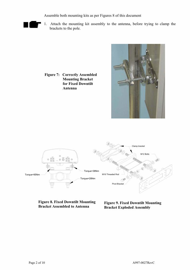
Assemble both mounting kits as per Figures 8 of this document
1. Attach the mounting kit assembly to the antenna, before trying to clamp the brackets to the pole.
Figure 7: Correctly Assembled Mounting Bracket for Fixed Downtilt Antenna
Torque=95NmTorque=28Nm
Torque=38Nm
Clamp bracket
M16 Threaded Rod
Pivot Bracket
M12 Bolts
Figure 8. Fixed Downtilt Mounting Bracket Assembled to Antenna
Page 2 of 10
Figure 9. Fixed Downtilt Mounting Bracket Exploded Assembly
A997-0027RevC

Installation Instructions – Mechanically Adjustable Downtilt Mounting Kit for 0-800mm Antennas - (APM-T-080-GL-E)
Assemble both mounting kits as per Figures 4 and 5 of this document.
1. Attach the upper and lower mounting kit assemblies to the antenna, before trying
to clamp the brackets to the pole.
2. Downtilt angles of 0°, 5°, 10° and 15° may be obtained with the correct adjustment of the tilt arm bracket. • For 0° downtilt the tilt arm may be stowed as show in Figure 6.
• 5°-15° downtilt can be achieved by aligning the corresponding hole in the tilt arm to the pivot bracket which mates against the mounting pole, as shown in Figure 5. The first hole is for 5° downtilt, with each consecutive hole resulting in an increased inclination of 5°.
Figure 4. Mechanically Adjustable Downtilt Figure 5. Mechanically Adjustable Downtilt B
Figure 6. Sample Antenna Positions Availa
Figure 5. Figure 4.
0ºDowntilt 5ºDowntilt tt
Figure
Page 3 of 10
10ºDowntil
Top Bracket Exploottom Bracket Explble With T-080-GL
6.
A997-002
15ºDowntil
ded View oded View -E Kit
7RevC
Installation Instructions - Mechanically Adjustable Downtilt Mounting Kits for 800
- 1100mm Antenna’s (APM-T-045-GL-E)
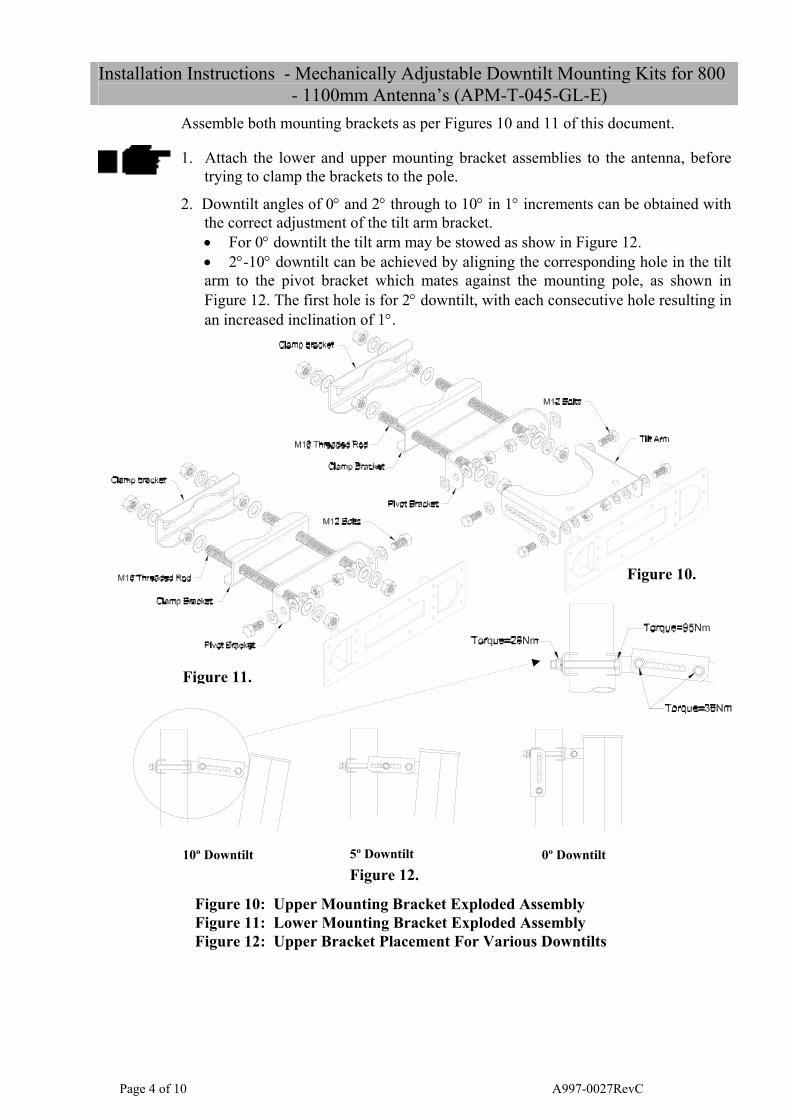
Assemble both mounting brackets as per Figures 10 and 11 of this document.
1. Attach the lower and upper mounting bracket assemblies to the antenna, before trying to clamp the brackets to the pole.
2. Downtilt angles of 0° and 2° through to 10° in 1° increments can be obtained with the correct adjustment of the tilt arm bracket. • For 0° downtilt the tilt arm may be stowed as show in Figure 12. • 2°-10° downtilt can be achieved by aligning the corresponding hole in the tilt arm to the pivot bracket which mates against the mounting pole, as shown in Figure 12. The first hole is for 2° downtilt, with each consecutive hole resulting in an increased inclination of 1°.
Figure 10.
Page 4 of
Figure 11.
t t
10º DowntilFigure 10: Upper MoFigure 11: Lower MoFigure 12: Upper Bra
10
5º Downtilt
unting Bracket Exploded Asunting Bracket Exploded Ascket Placement For Various
Figure 12.
0º Downtil
sembly sembly Downtilts
A997-0027RevC
Installation Instructions - Mechanically Adjustable Downtilt Mounting Kits for 1100-1500mm Antenna’s (APM-T-041-GL-E).
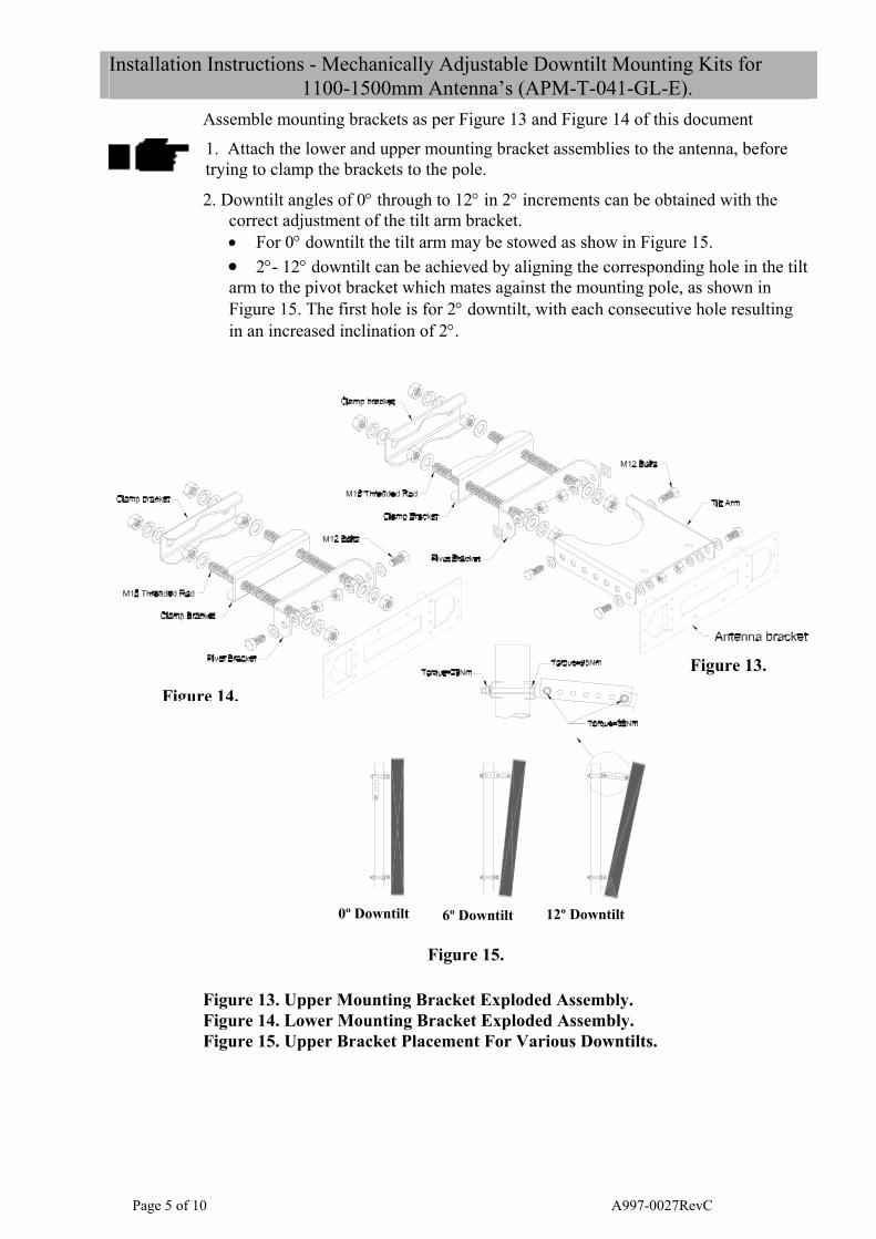
Assemble mounting brackets as per Figure 13 and Figure 14 of this document 1. Attach the lower and upper mounting bracket assemblies to the antenna, before trying to clamp the brackets to the pole.
2. Downtilt angles of 0° through to 12° in 2° increments can be obtained with the correct adjustment of the tilt arm bracket. • For 0° downtilt the tilt arm may be stowed as show in Figure 15. • 2°- 12° downtilt can be achieved by aligning the corresponding hole in the tilt arm to the pivot bracket which mates against the mounting pole, as shown in Figure 15. The first hole is for 2° downtilt, with each consecutive hole resulting in an increased inclination of 2°.
Figure 13.
.
Pag
Figure 14
Figure 13. UpperFigure 14. LowerFigure 15. Upper
t t t
e 5 of 10
0º Downtil
Mounting Br Mounting Br Bracket Plac
F
6º Downtil
acket Explodeacket Explodeement For Va
igure 15.
12º Downtil
d Assembly. d Assembly.
rious Downtilts.
A997-0027RevC

Installation Instructions - Mechanically Adjustable Downtilt Mounting Kits for 1500-2700mm Antenna’s (APM-T-029-GL-E).
Assemble mounting brackets as per Figure 17 and Figure 18 of this document
1. Attach the lower and upper mounting bracket assemblies to the antenna, before trying to clamp the brackets to the pole.
2. Downtilt angles of 0° through to 8° in 1° increments can be obtained with the correct adjustment of the tilt arm bracket. • For 0° downtilt the tilt arm may be stowed as show in Figure 19. • 1°- 8° downtilt can be achieved by aligning the corresponding hole in the tilt arm to the pivot bracket which mates against the mounting pole, as shown in Figure 19. The first hole is for 1° downtilt, with each consecutive hole resulting in an increased inclination of 1°.
Figure 16: Correctly Assembled Mounting Bracket for Mechanically Adjustable Downtilt Antenna
Clamp bracket
M16 Threaded Rod
Clamp Bracket
Pivot Bracket
M12 Bolts
Tilt Arm
Torque=38Nm
Torque=28NmTorque=95Nm
Fi bracket 0° tilt
Antenna bracket
Antenna Bracket
Pivot Bracket
Clamp Bracket
M16 Threaded Rod
Clamp bracket
M12 Bolts
Figure 17: Upper Mountin
Figure 18: Lower Mountin
Figure 17. Figure 18.
Figure 3. Upper
0º Downtilt Figure 4. Upper bracket 4° tilt
4º Downtilt gure 5. Upper bracket 8° tilt
8º Downtilt
Figure 19: Upper Bracket
Page 6 of 10
Figure 19.
g Brackets Exploded Assembly
g Bracket Exploded Assembly
Placement For Various Downtilts
A997-0027RevC

Operation of Antennas
Manual Electrically Adjustable Downtilt Antennas
The beam downtilt below the horizon is adjusted in the range of 0° to 10° by rotating the hex socket located at the bottom of the antenna (see Figure 20). Turning the hex socket in a clockwise direction increases the beam downtilt below the horizon. Turning the hex socket in an anti-clockwise direction decreases the beam downtilt below the horizon. Beam downtilt setting can be read off the scale at the base of the antenna.
AISG Compliant Adjustable Downtilt Antennas - Fitted with Remote Downtilt Adjustment
AISG Compliant antennas are compatible with AISG compliant control unit equipment, such as the RFS CNI-P2A20 AISG controller. For operation of downtilt using AISG compliant controllers see the controller documentation.
WARNING: During downtilt adjustment ensure the hex socket is not turned past the range of 0° to 10° as shown on the downtilt indicator scale. Forcing the hex adjustment beyond this point may lead to damage of the downtilt mechanism. Using power drills and electric screwdrivers to adjust downtilt may also lead to damage of the downtilt mechanism.
WARNING: Do not adjust the downtilt when the temperature is below -20º C. Adjustment below this temperature may lead to damage of the downtilt mechanism.
Figure 20: Single Band Antenna with connections labelled
Figure 21: Dual Band
2500 MHz / 2500 MHz
or
3500Mhz / 3500Mhz Antenna with connections labelled
Tilt adjust and scale
(Band 1)
AISG interface
+45° °
Tilt adj & s(Band 2
-45°
Page 7 of 10
-45
AISG Interface cale )
Tilt adj & scale (Band 1)
+45° +45° -45°
A997-0027RevC

Figure 22: Dual Band 900 MHz / 2000 MHz Antenna with connections
labelled
Figures 20, 21 and 22 show the configuration of the positive and negative slant polarization ports for single and multi band antennas. The tilt adjuster scale and port for remote interface is also highlighted.
Electrically Adjustable Downtilt Antennas – Indicator Scale
The downtilt angle in degrees below the horizon is read from the angle indicator scale. The downtilt scale is read from face of the antennas base plate at the point where the scale protrudes. As the downtilt is increased, the indicator scale protrudes further past the face, revealing further graduations of degrees.
Remote Electrical Tilt
AISG1.1: When using AISG1.1, a multiband antenna will report to the AISG1.1 controller as multiple antennas, each with a single band. Each band of the antenna will report a different serial number. For example, a tri band antenna with serial number 60051007 will report to the controller three individual antennas with serial numbers 600510071, 600510072, 600510073, where the last digit represents the band of the antenna. AISG2: When using AISG2.0, a multiband antenna will report to the AISG2.0 controller as a single antenna with multiple bands. Each band of the antenna is accessible through the controller. ANTENNA BANDS: In a dual band antenna, AISG band 1 is the RF low frequency band of the antenna. In a dual-band antenna with both RF bands operating in the same frequency spectrum, the antenna on the left when looking from behind the antenna is designated as AISG band 1. In a tri-band antenna, the RF low frequency band is designated as AISG band 1. The RF high frequency band closest to the base of the antenna is designated as AISG band 2 (as shown in Figure 25). The RF high frequency band closest to the top of the antenna is designated as AISG band 3.
AISG Interface
+45° 2000 MHz
-45° 2000 MHz
+45° 900 MHz
-45° 900 MHz
900 MHz tilt adj & scale (Band 1)
2000 MHz tilt adj & scale (Band 2)
Page 8 of 10 A997-0027RevC
SAFETY WARNING!
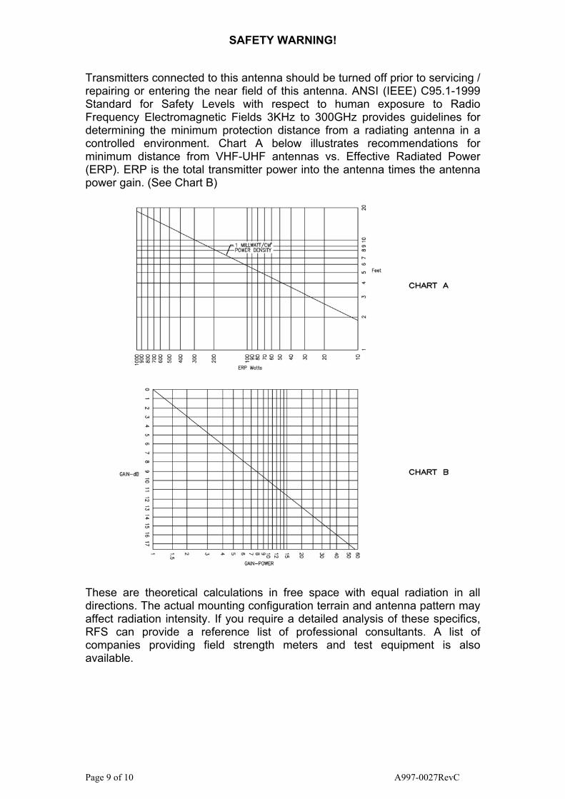
Transmitters connected to this antenna should be turned off prior to servicing / repairing or entering the near field of this antenna. ANSI (IEEE) C95.1-1999 Standard for Safety Levels with respect to human exposure to Radio Frequency Electromagnetic Fields 3KHz to 300GHz provides guidelines for determining the minimum protection distance from a radiating antenna in a controlled environment. Chart A below illustrates recommendations for minimum distance from VHF-UHF antennas vs. Effective Radiated Power (ERP). ERP is the total transmitter power into the antenna times the antenna power gain. (See Chart B)
These are theoretical calculations in free space with equal radiation in all directions. The actual mounting configuration terrain and antenna pattern may affect radiation intensity. If you require a detailed analysis of these specifics, RFS can provide a reference list of professional consultants. A list of companies providing field strength meters and test equipment is also available.
Page 9 of 10 A997-0027RevC

This product was designed and manufactured as a component of a professional communication system. It is intended to be installed by a professional installer. If you are not a professional installer, please contact your dealer for professional assistance.
WARNING! INSTALLATION
OF THIS PRODUCT NEAR POWER LINES
IS DANGEROUS FOR YOUR SAFETY;
FOLLOW THE GENERAL SAFETY DIRECTIONS
Each year, hundreds of people are killed, mutilated, or receive severe permanent injuries when attempting to install or remove an antenna. In many of these cases, the victim was aware of the danger of electrocution, but did not take adequate steps to avoid the hazard. For your safety, and a proper installation, please READ and FOLLOW the safety precautions that follow – THEY MAY SAVE YOUR LIFE. Save these instructions for future reference. The same precautions will apply when dismantling an antenna. GENERAL SAFETY DIRECTIONS
1. Select your installation site with safety, as well as performance, in mind. Remember: ELECTRIC POWER LINES, PHONE LINES AND GUY WIRES LOOK ALIKE. FOR YOUR SAFETY, ASSUME THAT ANY OVERHEAD LINES CAN KILL YOU.
2. Call your electric power company. Tell them your plans and ask them to come look at your proposed installation. This islittle inconvenience, considering YOUR LIFE IS AT STAKE.
3. Plan your installation procedure carefully and completely before you begin. Successful raising of a mast or tower is largely a matter of coordination. Each person should be assigned to a specific task, and should know what to do and when to do it. One person should be designated as the “boss” of the operation to call out instructions and watch for signs of trouble.
4. When installing your antenna, REMEMBER: DO NOT use a metal ladder. DO NOT work on a wet or windy day. especially during electrical storms or when there is thunder and lightning in the area. DO dress properly – shoes with rubber soles and heels, rubber gloves, long sleeve shirt or jacket.
5. If the assembly starts to drop, get away from it and let it fall. REMEMBER: The antenna, mast, cable, and metal guy lines are excellent conductors of electrical current. Even the slightest touch of any of these parts to a power line completes an electrical path through the antenna and the installer – THAT’S YOU!
6. If any part of the antenna system should come in contact with
a power line, DON’T TOUCH IT OR TRY TO REMOVE IT YOURSELF. CALL YOUR LOCAL POWER COMPANY. They will remove it safely.
7. If an accident should occur with the power lines: DON’T grab
hold of the person in contact with the antenna and power lineor you too will be electrocuted. Use a DRY board, stick or rope to push or pull the victim away from the antenna. If the victim has stopped breathing, administer artificial respiration – and stay with it. Have someone call for medical help.
A-44965 REV 4, 08-DEC-03
Page 10 of 10 A997-0027RevC