Embed Size (px)
Citation preview

EUROGRAPHICS ’2000 / M. Gross and F.R.A. Hopgood(Guest Editors)
Volume 19, (2000), Number 3
Multiresolution Shape Deformationsfor Meshes with Dynamic Vertex Connectivity
Leif P. Kobbelt
Thilo Bareuther Hans-Peter Seidel
AbstractMultiresolution shape representation is a very effective way to decompose surface geometry into several levels ofdetail. Geometric modeling with such representations enables flexible modifications of the global shape while pre-serving the detail information. Many schemes for modeling with multiresolution decompositions based on splines,polygonal meshes and subdivision surfaces have been proposed recently. In this paper we modify the classicalconcept of multiresolution representation by no longer requiring a global hierarchical structure that links the dif-ferent levels of detail. Instead we represent the detail information implicitly by the geometric difference betweenindependent meshes. The detail function is evaluated by shooting rays in normal direction from one surface tothe other without assuming a consistent tesselation. In the context of multiresolution shape deformation, we pro-pose a dynamic mesh representation which adapts the connectivity during the modification in order to maintaina prescribed mesh quality. Combining the two techniques leads to an efficient mechanism which enables extremedeformations of the global shape while preventing the mesh from degenerating. During the deformation, the detailis reconstructed in a natural and robust way. The key to the intuitive detail preservation is a transformation mapwhich associates points on the original and the modified geometry with minimum distortion. We show severalexamples which demonstrate the effectiveness and robustness of our approach including the editing of multireso-lution models and models with texture.
1. Introduction
With the increasing resolution and complexity of geomet-ric models in computer graphics applications, the necessityof hierarchical representations is getting more and more im-portant. Multiresolution decompositions for highly detailedsurface geometries are likely to become the future standardsince they enable the surface complexity to be adapted to theavailable (hardware) resources and the quality requirementsof a given application. In addition to complexity control,multiresolution representations enable intuitive and power-ful modeling operations since modifications can be appliedon any level of detail without affecting coarser levels andwith automatic adaption of the finer detail features.
A multiresolution representation consists of a sequence ofdifferently detailed approximations 0 m of an origi-nal surface m. Alternatively, m can also be decom-posed into a sequence of detail components i i 1 i.The efficient use of multiresolution representations requiresto find an appropriate mathematical description for the sur-faces i. For this purpose hierarchical splines have been
Max-Planck-Institute for Computer Sciences, Im Stadtwald,
66123 Saarbrücken, Germany, [email protected]
used in 9 10 where the displacement i between successivelevels i is defined by pasting tensor-product splines ontoeach other.
To get rid of the topological restrictions emerging fromthe use of tensor-product basis functions, wavelet techniqueshave been generalized to surfaces with arbitrary topology in25 30 32 39. Here, the surfaces i are represented by subdivi-sion schemes what can be considered as a compromise be-tween spline-surfaces and triangle meshes.
Subdivision schemes exploit the convergence of splinecontrol meshes to the associated surface under knot inser-tion. The corresponding algorithms apply a set of general-ized knot insertion operators (refinement rules) which gen-erate a sequence of finer and finer meshes eventually con-verging to a smooth limit surface. 2 6 24 17 38. Consequently,subdivision surfaces are in fact triangle meshes but with anadditional mechanism to change the mesh resolution. This isthe reason why subdivision techniques are very well suitedfor computer graphics applications where most of the data isrepresented by triangle meshes anyway.
In the context of subdivision schemes, the surfaces i nat-urally emerge from an i-times refined base mesh 0. Themajor drawback of this surface representation is that subdi-
c
The Eurographics Association and Blackwell Publishers 2000.Published by BlackwellPublishers, 108 Cowley Road, Oxford OX4 1JF, UK and 350 Main Street, Malden, MA02148, USA.

Kobbelt et al. / Multiresolution Deformations
vision connectivity is mandatory for the original (fine) mesh m m. As most of the mesh data sets do not come in thisform, remeshing is required as a preprocessing step 7 22 20.
In 19 and 13 multiresolution techniques have been gener-alized to meshes with arbitrary connectivity by exploitingfine-to-coarse hierarchies emerging from the application ofa mesh decimation algorithm 31 29 15 11 18. This enables mul-tiresolution functionality for arbitrary meshes. However, theprogressive mesh type multiresolution representations arestill associated with the structure of the given mesh. Thismeans that the techniques proposed there cannot be general-ized to modeling operations that change the mesh connectiv-ity.
What is common to all these approaches is the fact thatthe multiresolution representations always impose a globalhierarchical structure on the data. In the case of hierarchicalsplines and subdivision surfaces, this structure is provided bythe common domain Ω on which all surfaces i are param-eterized. For the fine-to-coarse mesh hierarchies this struc-ture is determined by the connectivity of the finest resolutionmesh.
The existence of a global structure implies that the repre-sentations of the different levels of detail i are not indepen-dent from each other. Hence, we cannot perform arbitrarychanges on each level. In the context of surface modelingthis is a severe restriction since drastic modifications of thegeometry cause strong changes in the surface metric. Hence,reparameterization (of the surface) or restructuring (of themesh) might be necessary to preserve the surface quality.
In this paper we therefore propose a new approach to mul-tiresolution representation and modeling which enables thedecomposition of arbitrary geometries and does not requireany compatibility condition between the levels i (other thanthat they are differently detailed approximations of the samesurface). The basic idea is to represent the detail informa-tion i between the levels by a displacement field withoutassuming any specific parameterization of the involved sur-faces i and i 1. This enables us to perform arbitrary mod-ifications on each level of a multiresolution decomposition.
The paper is organized as follows: In Section 2, we ex-plain the details of the multiresolution representation whichis the basis for the multiresolution shape deformation tech-nique explained in Section 3. Section 4 introduces mesheswith dynamic connectivity that enable arbitrary shape mod-ifications while preserving the quality of the tesselation. InSection 5 we explain a simple animation technique based oncontrol ellipsoids which span a membrane surface. In Sec-tion 6 we show how the multiresolution shape deformationscan be used to globally deform meshes with changing con-nectivity while the geometric detail is preserved. In Section 7we demonstrate that the same techniques can also be appliedto the deformation of textured models. Finally, we give somehints concerning the efficient implementation of the algo-rithm in Section 8.
2. Multiresolution Representation
Given an arbitrary surface m, a multiresolution decompo-sition consists of a sequence of topologically equivalent sur-faces m 1 0 that approximate m with decreasinglevel of detail. The difference i i 1 i between twosuccessive surfaces is the detail on level i which is added orremoved when switching between the two approximations.The reconstruction
m i i
m 1
of the original surface m can start on any level of detail i.
Multiresolution editing means that on some level of de-tail, the surface i is replaced by i . This operation does nothave any effect on 0 i 1. However i 1 and hence i 1 m change since the (unchanged) detail informa-tion i m 1 is now added to the modified base surface i for the reconstruction of m.
To guarantee the intuitive preservation of shape character-istics after a modification on some lower level of detail, thisbasic setting has to be extended in the sense that the detail in-formation i is encoded with respect to local frames. Theseframes are aligned to the surface geometry of i
9 10 19 39. Ifthe surfaces i are defined as parameteric functions over acommon parameter domain Ω, the use of local frame codingfor the details i makes the definition of a proper hierarchyof nested function spaces (multiresolution analysis) impossi-ble since the shape of i influences the structure of all higherfrequency subspaces.
A closely related concept to local frame coding is the rep-resentation of detail information i by a displacement mapon i
3 21 28. Let Ni be a continuous vector field defined onthe surface i which assigns a normal vector Ni
p to every
point p i. Then the detail information i can be repre-sented by a scalar function λi such that
i 1 q p i : q p λi
p Ni
p
From the continuity of the normal field Ni it follows that i and i 1 have the same topology. Nevertheless, self in-tersections of i 1 are possible if λi
p is larger than the
minimum curvature radius at p. As λip is unique, no point
of i can be mapped to several points on i 1. This impliessome restrictions on the geometric relation between i and i 1.
When i is transformed into i by some modeling oper-ation, the reconstruction of i 1 is done by using the un-changed detail function λi with respect to the new normalfield N i on i (cf. Fig. 2). Hence, to perform a multiresolu-tion modification, we need a (inverse) transformation map Twhich associates each point p on the new surface i to a lo-cation p T
p on the old surface i. The modified surface
i 1 is then given by
i 1 q p i : q p λ i p N i p with
λ i p λi T p c
The Eurographics Association and Blackwell Publishers 2000.

Kobbelt et al. / Multiresolution Deformations
Figure 1: The multiresolution shape deformation is evaluated from left to right: 1, 0,
, 0, and 1. First we have theoriginal geometry 1 and its low-frequency approximation 0. The displacement function λ is sampled by shooting rays from 0 in normal direction onto 1. The middle mesh is the linking mesh
between the original and the modified low frequency
meshes 0 and 0 respectively. The vertices of
are projected onto the geometry of 0. Hence, the detail function λ does notchange significantly if we replace 0 by
when sampling λ. On the other hand,
has the same connectivity as 0 (middle
right) which establishes a one-to-one correspondence between the points on both surfaces. Finally, the deformed surface 1with reconstructed detail is obtained by shifting the vertices of 0 in normal direction by the amount λ.
Figure 2: Left: The geometry i 1 (grey) is defined rela-tive to the circle i (black). For p cos
t sin
t T i we
have λp 1
4 cos5t . Right: When deforming the base ge-
ometry i i the modified geometry i 1 is reconstructedby using the same detail function λ with respect to the newnormal field N i on i . To evaluate λ at the correct location,the points on i and i must be linked by a transformationmap T .
This general definition for multiresolution representationsenables us to define the different levels of detail completelyindependent from each other. There is no need for a globalhierarchical structure like in the approaches that are basedon a nested sequence of spaces or grids 25 32 39. We do noteven have to use the same surface type (parametric, implicit,polygonal meshes) for all surfaces i. The only require-ments are that we have to be able to compute normal vectorsNi and find ray-intersections. Under these assumptions it isnot necessary to set up an explicit formulation for the detailfunctions λi since the evaluation of λi at some point p ican be accomplished by computing the intersection of theray p
λNip with the surface i 1 on demand.
3. Multiresolution shape deformation
In computer graphics and geometric modeling, we have sev-eral standard techniques for the definition of surface geome-try. Besides the implicit definition (iso-surfaces) and the pa-rameteric definition (spline-patches) we find the explicit def-
inition by polygonal meshes particularly useful. Especiallytriangle meshes can be considered the most versatile repre-sentation for general free-form surface geometry. Due to thesimplicity and robustness of algorithms operating on trianglemeshes, we can approximate arbitrarily complicated objectsby sufficiently refined tesselations. With increasing resolu-tion (refinement level) the non-smooth character of the piece-wise linear approximations is quickly vanishing and can beforced below any prescribed tolerance. The complexity ofexplicit representations can be reduced by efficient schemesto compress the mesh data 4 12 35.
In the sequel we will therefore focus on the use of trianglemeshes for the representation of the surfaces i in our mul-tiresolution decomposition. Notice that despite their discretenature, triangle meshes represent continuous surfaces. More-over, we can easily define a continuous normal field by linearinterpolation of vertex normals. Hence, given two meshes iand i 1, we can evaluate the detail function λi at arbitrarylocations on the mesh i. This means in particular that wecan arbitrarily super-sample the detail function without anyrestrictions imposed by the actual resolution of the under-lying tesselation. This is an important observation that weexploit when a multiresolution shape deformation stronglychanges (e.g., stretches) the global shape of an object.
For simplicity we restrict our explanation to a two-banddecomposition of the given geometry. The generalization tomulti-band decompositions is straightforward since the eval-uation/reconstruction procedure on the ith level of detail re-cursively calls the same evaluation procedure for the nextcoarser approximation level. Without loss of generality wefurther assume that a single multiresolution modeling oper-ation applies modifications only on one frequency band.
Let the two-band representation of a surface be given bytwo triangle meshes 0 and 1 with arbitrary connectivityeach. The multiresolution deformation replaces the mesh 0by 0 (again with a completely different connectivity). Wewant to reconstruct the result of the operation 1.
According to the multiresolution representation of the lastsection, we find points q on 1 by displacing points p 0
c
The Eurographics Association and Blackwell Publishers 2000.

Kobbelt et al. / Multiresolution Deformations
in normal direction. The distance λ p by which p ismoved, has to be sampled from the displacement map thatis implicitly defined by the geometries of the two originalsurfaces 0 and 1. Hence, suppose we know the transfor-mation map T , we can compute the point p T
p on 0
and shoot a ray p λN0
p . The distance to the first inter-
section point on 1 yields the value λp : λ p .
The remaining question is how to find an appropriate map
T : 0 0 This is not trivial since 0 and 0 can have different geom-etry and different connectivity. Yet, the quality of the detailreconstruction strongly depends on the distortion caused byT .
We propose to generate the map T by constructing an ad-ditional mesh
which has the same connectivity as 0 and
the same geometry as 0, i.e. whose vertices p lie onthe continuous surface 0. Due to the fact that
and 0 are
smooth tesselations (low frequency approximations) whichhave approximately the same geometry, the difference be-tween the displacement function λ sampled from either meshis neglectible. One the other hand, since
and 0 have the
same connectivity, it is trivial to establish a one-to-one cor-respondence between both by using a barycentric parameter-ization within each triangle. Hence, for a given point p on 0 we can compute the displacement value λ p by shoot-ing a ray in normal direction from the corresponding point pon
.
Fig. 1 shows all the meshes involved in this multiresolu-tion modeling operation. The distortion of the transforma-tion map T and hence the quality of the detail reconstructionis determined by the distribution of the vertices of
on the
surface 0. This distribution has to optimize two conflictingobjectives. First, the points should be distributed evenly over 0 in order to guarantee a uniform sampling densitiy for λ.On the other hand, the relative position of neighboring ver-tices should be similar to the corresponding configuration onthe mesh 0 in order to minimize local distortions (e.g. pre-serve the triangle’s aspect ratios). The degree of difficultyfor this optimization task depends on the geometric differ-ence between the shapes of 0 and 0.
Let us assume that the shape difference between 0 and 0 is small, i.e. both meshes have only a small Hausdorff-distance from each other. This assumption does not restrictthe set of possible modeling operations since we can de-compose every drastic shape deformation into a sequenceof small deformations (in the Hausdorff-sense). In order tocompute the transformation map T for a big deformation wesimply concatenate the corresponding maps for the small de-formations.
For the generation of
we start by copying the connectiv-ity of 0 and apply two operators that control the distributionof the vertices p on the surface 0. The first operator P(project) computes initial positions for each vertex p .The second operator D (distribute) then shifts the points pin order to distribute them more evenly over the surface 0.This operator reduces the global distortion of the map T .
In Sect. 8 we explain a simple and efficient method to findthe closest triangle F
A B C 0 to a vertex q 0.The P operator projects each vertex q 0 onto the nearestpoint q on F (this is not necessarily an orthogonal projec-tion) which yields the initial position for the correspondingvertex of
. After the application of the P operator, the dis-
tribution of the vertices in the initial mesh
are ”as similaras possible” to the distribution of the vertices in 0.
The D operator equalizes the density of the vertices q scattered over the surface 0. For this, we first estimate thelocal density d for each vertex q, e.g., by computing the av-erage length of the adjacent edges. We then update the vertexpositions for all q by the density weighted umbrella rule19 5
q 1
∑ j d j
n 1
∑j 0
d j q j (1)
where n is the valence of q and q j are its direct neighborswith their corresponding density d j . The effect of the weightcoefficients is that vertices with low point density (large av-erage edge length) pull harder. Hence, the density egalizationis performed more aggressively. On the other hand, neigh-boring vertices with high density have reduced attractionwhich avoids clustering effects (shrinking) known from theuniform umbrella operator 19 34.
After the application of (1) the vertices q are no longerlying on the surface 0. Hence, another projection P ontothe nearest triangle concludes the D operation. Usually, theD operator has to be applied several times to obtain a goodvertex distribution.
Fig. 1 shows a simple example for the detail reconstruc-tion based on the transformation map T after the shape de-formation. In Sect. 6 and 7 we will see more examples whichdemonstrate that this basic technique enables strong mul-tiresolution deformations while keeping the distortion of themap T minimal. However, before we go into the details ofmultiresolution animation, we have to define a triangle meshbased surface representation which is flexible enough to per-form arbitrary shape deformations.
4. Dynamic Connectivity Meshes
In general, a triangle mesh is defined by the position ofits vertices pi and their connectivity
pi p j . When modi-
fying the shape of an object (not its topology) it is oftenconsidered sufficient to merely change the position of thevertices but not to adapt their connectivity. Since the actualcontinuous surface of a triangle mesh is defined by piece-wise linear interpolation between the vertices, the modifica-tion of each control vertex p is equivalent to changing thevector valued coefficient of a locally supported fixed piece-wise linear basis function (hat-function) centered at p. Asglobal modifications usually require to update the positionsof many vertices, such modeling operations are controlledby coarse scale basis functions (shape functions) which aresuper-imposed over a whole subregion of the given mesh.
c
The Eurographics Association and Blackwell Publishers 2000.

Kobbelt et al. / Multiresolution Deformations
Figure 3: Moving a selection of vertices in a triangle mesh causes distortion of the adjacent triangles (far left). This effectcannot be removed by uniform subdivision (center left). However, dynamically restructuring the mesh yields better shapedtriangles (right). The resolution of the mesh can be controlled by prescribing the minimum and maximum edge length.
The major problem emerging from this kind of geomet-ric modification is that moving a selection of mesh verticescauses a distortion of the adjacent triangles and hence affectsthe quality of the mesh (cf. Fig. 3). Applying uniform 1-to-4splits in regions where the discrete curvature is above somethreshold or the length of the edges exceeds a prescribedbound 39 does not solve this problem since uniform splits donot improve the aspect ratio of the triangles. Moreover, weare interested in finding a surface representation where thenumber of triangles is proportional to the total surface area.However, when using uniform refinement (subdivision con-nectivity), the number of triangles increases quadratically ifthe mesh is streched in one direction (cf. Fig. 3).
We therefore prefer a mesh optimization technique similarto 16 33 37 which uses simple operations to improve the qual-ity of a given mesh by changing its connectivity. Our goalis to find a mesh representation which guarantees a certainmesh quality according to the following requirements 1:
No edge should be shorter than εmin No edge should be longer than εmax A vertex’ valence should be six. Long and thin triangles should be avoided
We call this representation dynamic triangle meshes sinceevery geometric modification (alteration of the vertices’ po-sition) is followed by a restructuring of the mesh, i.e., bythe application of simple operations which change the meshconnectivity in order to re-establish the above quality re-quirements. As the surface representation is not static any-way, it is not necessary to treat the quality requirements ashard limits. In order to avoid strong distortions in the mesh itis sufficient to at least reduce the number of violations withevery restructuring step. This guarantees that the mesh qual-ity stays sufficiently close to an optimal configuration.
The restructuring is performed in several stages. First alledges which are shorter than εmin are removed by collapsingthe two end-vertices. To avoid problems with ”chains” ofshort edges, we collapse that end-vertex with lower valence
Figure 4: Small edges are removed by edge collapses. Theaccumulation of edge collapses (middle) is prevented by col-lapsing into the vertex with higher valence (bottom). Thissimple heuristic works because high valence vertices stayfixed and every collapse reduces the number of adjacentshort edges. Moving a high valence vertex v, however, canlead to an unbounded accumulation of edge collapses sincenew short edges can become adjacent to v.
into the one with higher (cf. Fig. 4). Then, all edges whichare longer than εmax are split by inserting a new vertex at itsmid-point. The two adjacent triangles are bisected accord-ingly (cf. Fig. 5). Notice that the upper and the lower boundon the edge lengths are only compatible if εmax
2εminsince otherwise the edge split operation would generate twoinvalid edges.
After all edge lengths lie within the target interval εmin εmax we perform edge-flipping in order to regularize
c
The Eurographics Association and Blackwell Publishers 2000.
Kobbelt et al. / Multiresolution Deformations
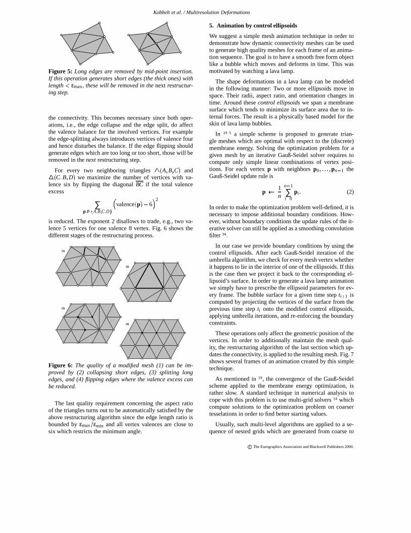
Figure 5: Long edges are removed by mid-point insertion.If this operation generates short edges (the thick ones) withlength εmax, these will be removed in the next restructur-ing step.
the connectivity. This becomes necessary since both oper-ations, i.e., the edge collapse and the edge split, do affectthe valence balance for the involved vertices. For examplethe edge-splitting always introduces vertices of valence fourand hence disturbes the balance. If the edge flipping shouldgenerate edges which are too long or too short, those will beremoved in the next restructuring step.
For every two neighboring triangles
A B C and C B D we maximize the number of vertices with va-
lence six by flipping the diagonal BC if the total valenceexcess
∑p A B C D
valencep 6 2
is reduced. The exponent 2 disallows to trade, e.g., two va-lence 5 vertices for one valence 8 vertex. Fig. 6 shows thedifferent stages of the restructuring process.
(1)
(2)
(3)
(4)
Figure 6: The quality of a modified mesh (1) can be im-proved by (2) collapsing short edges, (3) splitting longedges, and (4) flipping edges where the valence excess canbe reduced.
The last quality requirement concerning the aspect ratioof the triangles turns out to be automatically satisfied by theabove restructuring algorithm since the edge length ratio isbounded by εmax εmin and all vertex valences are close tosix which restricts the minimum angle.
5. Animation by control ellipsoids
We suggest a simple mesh animation technique in order todemonstrate how dynamic connectivity meshes can be usedto generate high quality meshes for each frame of an anima-tion sequence. The goal is to have a smooth free form objectlike a bubble which moves and deforms in time. This wasmotivated by watching a lava lamp.
The shape deformations in a lava lamp can be modeledin the following manner: Two or more ellipsoids move inspace. Their radii, aspect ratio, and orientation changes intime. Around these control ellipsoids we span a membranesurface which tends to minimize its surface area due to in-ternal forces. The result is a physically based model for theskin of lava lamp bubbles.
In 19 5 a simple scheme is proposed to generate trian-gle meshes which are optimal with respect to the (discrete)membrane energy. Solving the optimization problem for agiven mesh by an iterative Gauß-Seidel solver requires tocompute only simple linear combinations of vertex posi-tions. For each vertex p with neighbors p0 pn 1 theGauß-Seidel update rule is
p 1n
n 1
∑i 0
pi (2)
In order to make the optimization problem well-defined, it isnecessary to impose additional boundary conditions. How-ever, without boundary conditions the update rules of the it-erative solver can still be applied as a smoothing convolutionfilter 34.
In our case we provide boundary conditions by using thecontrol ellipsoids. After each Gauß-Seidel iteration of theumbrella algorithm, we check for every mesh vertex whetherit happens to lie in the interior of one of the ellipsoids. If thisis the case then we project it back to the corresponding el-lipsoid’s surface. In order to generate a lava lamp animationwe simply have to prescribe the ellipsoid parameters for ev-ery frame. The bubble surface for a given time step ti 1 iscomputed by projecting the vertices of the surface from theprevious time step ti onto the modified control ellipsoids,applying umbrella iterations, and re-enforcing the boundaryconstraints.
These operations only affect the geometric position of thevertices. In order to additionally maintain the mesh qual-ity, the restructuring algorithm of the last section which up-dates the connectivity, is applied to the resulting mesh. Fig. 7shows several frames of an animation created by this simpletechnique.
As mentioned in 19, the convergence of the Gauß-Seidelscheme applied to the membrane energy optimization, israther slow. A standard technique in numerical analysis tocope with this problem is to use multi-grid solvers 14 whichcompute solutions to the optimization problem on coarsertesselations in order to find better starting values.
Usually, such multi-level algorithms are applied to a se-quence of nested grids which are generated from coarse to
c
The Eurographics Association and Blackwell Publishers 2000.

Kobbelt et al. / Multiresolution Deformations
Figure 7: A bubble object can be animated by spanning a membrane skin around a set of control ellipsoids. Since the skin isrepresented by a dynamic connectivity mesh, the quality of the triangular faces is guaranteed by restructuring the mesh betweenthe frames.
fine by uniform refinement of a coarse base mesh. In 19 themethod is generalized to meshes with arbitrary connectiv-ity where a hierarchy of nested grids can be generated fromfine to coarse by incremental mesh decimation 11 15 18 29 31.In the case of dynamic connectivity meshes, however, wecannot generate a sequence of nested grids since the actualconnectivity is determined by the restructuring step and un-known a priori.
We therfore use a multi-level solver which controls thecoarseness of the tesselation by adapting the bounds for theedge lengths εmin and εmax. For every frame of the anima-tion sequence, we start with rather large values for εmin andεmax and apply several steps of alternating umbrella updatesand projection onto the control ellipsoids (inner loop). Thenwe slowly decrease the bounds by some factor q 1. In therestructuring step this triggers edge split operations whichrefine the mesh. The alternating mesh optimization and re-structuring is repeated until the target resolution is reached(outer loop). The following pseudo-code implements themulti-level solver.
for each frameinit εmin, εmaxwhile (εmax
τ)while not convergence
minimize energyproject to ellipsoid
εmin q, εmax
qrestructure
Fig. 8 shows several intermediate meshes of this process.The generalized multi-level version of the membrane energyminimization is significantly faster than plain Gauß-Seideliterations — especially for high target resolutions. For mod-erately complex models ( 104
) we can easily computeseveral frames per second on a standard graphics worksta-tion (SGI O2, R10K).
As demonstrated in 27, the control ellipsoid animationtechnique can also be applied to geometric modeling. Thedesigner can use control ellipsoids as modeling tools to pushor pull the surface. Even more general shapes are possiblefor the tool geometry as long as the inside test can be com-puted effectively and the projection onto the tool’s surface is
well-defined. Similar to 19 37 we could also use the thin-plateenergy instead of the membrane energy and we could restrictthe influence of a modification to a presribed sub-region ofthe mesh.
6. Animating a multiresolution object
We now apply the multiresolution shape deformation tech-nique to surface representations based on triangle mesheswith dynamic connectivity. This enables us to compute ani-mation sequences where the deformation of the global shapeis prescribed while the detail information is preserved in anatural fashion. The shape deformation during the animationmight require to dynamically adapt the connectivity fromframe to frame in order to maintain the mesh quality. Hence,we have to be able to resample the detail function λ at arbi-trary locations since we cannot tell a priori where additionaldetail information will be required.
The basic idea is to take an arbitrary triangle mesh 1and a low-frequency approximation 0 as a two-band mul-tiresolution representation of the input data. The mesh 0is then animated, e.g., by using the control ellipsoid tech-nique. For every frame, the detail will be reconstructed byshifting the vertices of the current mesh in normal directionaccording to the resampled detail function λ.
For the computation of the animation sequence we needfour different meshes. First we need the low-frequency ap-proximation of the current frame current and the linkingmesh
current which has the same connectivity as current
but with vertex positions lying on the surface 0. This meshrepresents the current transformation map Tcurrent that linksthe points p on current to locations T
p on 0 where the
detail function λ has to be sampled in order to compute thedisplacement for the detail reconstruction at p. For the firstframe, both meshes are indentical to 0 (starting configu-ration).
As the animation progresses to the next frame, the newlow-frequency shape of the animated object is stored in next. We do not assume any coherence between the con-nectivities of current and next. For the proper reconstruc-tion of the detail, we have to find the new transformation mapTnext : next 0 which is difficult to compute directly
c
The Eurographics Association and Blackwell Publishers 2000.
Kobbelt et al. / Multiresolution Deformations
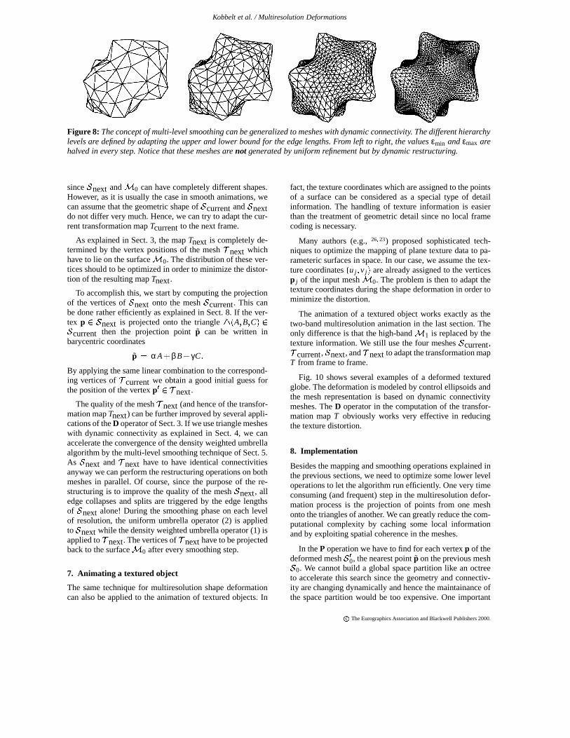
Figure 8: The concept of multi-level smoothing can be generalized to meshes with dynamic connectivity. The different hierarchylevels are defined by adapting the upper and lower bound for the edge lengths. From left to right, the values εmin and εmax arehalved in every step. Notice that these meshes are not generated by uniform refinement but by dynamic restructuring.
since next and 0 can have completely different shapes.However, as it is usually the case in smooth animations, wecan assume that the geometric shape of current and nextdo not differ very much. Hence, we can try to adapt the cur-rent transformation map Tcurrent to the next frame.
As explained in Sect. 3, the map Tnext is completely de-termined by the vertex positions of the mesh
next which
have to lie on the surface 0. The distribution of these ver-tices should to be optimized in order to minimize the distor-tion of the resulting map Tnext.
To accomplish this, we start by computing the projectionof the vertices of next onto the mesh current. This canbe done rather efficiently as explained in Sect. 8. If the ver-tex p next is projected onto the triangle
A B C
current then the projection point p can be written inbarycentric coordinates
p αA βB
γC By applying the same linear combination to the correspond-ing vertices of
current we obtain a good initial guess for
the position of the vertex p next.
The quality of the mesh
next (and hence of the transfor-mation map Tnext) can be further improved by several appli-cations of the D operator of Sect. 3. If we use triangle mesheswith dynamic connectivity as explained in Sect. 4, we canaccelerate the convergence of the density weighted umbrellaalgorithm by the multi-level smoothing technique of Sect. 5.As next and
next have to have identical connectivities
anyway we can perform the restructuring operations on bothmeshes in parallel. Of course, since the purpose of the re-structuring is to improve the quality of the mesh next, alledge collapses and splits are triggered by the edge lengthsof next alone! During the smoothing phase on each levelof resolution, the uniform umbrella operator (2) is appliedto next while the density weighted umbrella operator (1) isapplied to
next. The vertices of
next have to be projected
back to the surface 0 after every smoothing step.
7. Animating a textured object
The same technique for multiresolution shape deformationcan also be applied to the animation of textured objects. In
fact, the texture coordinates which are assigned to the pointsof a surface can be considered as a special type of detailinformation. The handling of texture information is easierthan the treatment of geometric detail since no local framecoding is necessary.
Many authors (e.g., 26 23) proposed sophisticated tech-niques to optimize the mapping of plane texture data to pa-rameteric surfaces in space. In our case, we assume the tex-ture coordinates
u j v j are already assigned to the vertices
p j of the input mesh 0. The problem is then to adapt thetexture coordinates during the shape deformation in order tominimize the distortion.
The animation of a textured object works exactly as thetwo-band multiresolution animation in the last section. Theonly difference is that the high-band 1 is replaced by thetexture information. We still use the four meshes current,
current, next, and
next to adapt the transformation mapT from frame to frame.
Fig. 10 shows several examples of a deformed texturedglobe. The deformation is modeled by control ellipsoids andthe mesh representation is based on dynamic connectivitymeshes. The D operator in the computation of the transfor-mation map T obviously works very effective in reducingthe texture distortion.
8. Implementation
Besides the mapping and smoothing operations explained inthe previous sections, we need to optimize some lower leveloperations to let the algorithm run efficiently. One very timeconsuming (and frequent) step in the multiresolution defor-mation process is the projection of points from one meshonto the triangles of another. We can greatly reduce the com-putational complexity by caching some local informationand by exploiting spatial coherence in the meshes.
In the P operation we have to find for each vertex p of thedeformed mesh 0, the nearest point p on the previous mesh 0. We cannot build a global space partition like an octreeto accelerate this search since the geometry and connectiv-ity are changing dynamically and hence the maintainance ofthe space partition would be too expensive. One important
c
The Eurographics Association and Blackwell Publishers 2000.

Kobbelt et al. / Multiresolution Deformations
observation, however, that leads to an efficient algorithm, isthat for two nearby vertices on 0 the corresponding clos-est points on 0 are very likely to be nearby as well. This istrue because 0 and 0 only have a rather small Hausdorff-distance (compared to their size).
As the P operation has to project all vertices of 0, wecan exploit this observation by enumerating the vertices in arecursive traversal algorithm such that the expected distancebetween successive vertices is small. In this case we can usethe projection point of the previous vertex as a starting pointfor finding the next projection point.
Suppose the vertex p 0 is projected onto p A B C 0 and q 0 is a vertex close to p then we
start with the triangle
A B C and compute
q A αN β
B A γ
C A
where N B A C A is the normal vector to
A B C . As we are only interested in the orthogonal pro-jection
1 β γ A βB
γC, it is sufficient to solve thesymmetric
2 2 -system
B A T B A C A T B A
B A T C A C A T C A β
γ P A T B A P A T C A
If the barycentric coordinates are positive, we have foundthe projected point q. Otherwise we proceed in any directionindicated by a negative barycentric coordinate. To terminatethe marching algorithm correctly we have to check for loops,i.e., for triangles that are visited twice. If this happens, thenthe closest point to q lies on an edge of 0. Once we detecta loop, we can easily compute the projected point by scal-ing the non-negative barycentric coordinates such that theysum to one. For sufficiently smooth meshes 0, this case isrelatively unlikely to occur.
The traversal by which the vertices of 0 are enumeratedis similar to algorithms that generate triangle strips 8. How-ever in our case we are not that much interested in long stripsbut more in avoiding far jumps during the traversal. Our al-gorithm starts with an arbitrary edge in the mesh. For thefirst vertex we have to find the projection point by brute-force testing. For the second and all subsequent vertices wecan use the above marching technique.
We recursively enumerate the vertices of 0 by depth-firsttraversal of a binary tree which is implicitly defined by theneighbor relation between the triangles (each node has threeneighbors, i.e., one parent and two children) 36. For everynew vertex q for which we have to compute the projection,we find at least one direct neighbor p that has already beenprocessed. Hence, we immediately find a nearby triangle on 0 to start the marching algorithm. Practical experimentsproved that the marching usually has to bridge only rathersmall distances. For example if both geometries 0 and 0have the same resolution we need less than two marchingsteps in average to reach the destination triangle.
In some rare cases, this procedure can fail to find the cor-rect projection point q. In these cases the wrongly reportedpoint typically lies quite far away on the opposite side ofthe mesh. This malfunction occurs if the starting triangle forthe marching procedure is too far from the actual projec-tion point. We can easily check the feasibility of a reportedprojection point q by testing its distance to the point q. Forexample in the animations controlled by moving ellipsoids,we know that the surface cannot move further than the max-imum shift of one of the ellipsoids plus its maximum changeof radius. Hence projection points which lie farther awaythan this distance must be wrong.
In practice, it turned out that the occurence of this error isvery rare. So we use a brute-force fall-back solution whichsimply tests the vertex agains all triangles of the mesh 0.This does not affect the overall performance of the algo-rithm.
9. Conclusions
In this paper we presented a new approach to multiresolutionfree-form deformations. Instead of defining a global hierar-chy across all levels of the multiresolution decomposition,we define detail information as the geometric difference be-tween two differently detailed approximations i and i 1of the same object with no further restrictions. The detail in-formation is implicitly represented as a displacement fieldwith respect to the normal vectors on i. The detail can besampled (evaluated) at arbitrary points by computing ray in-tersections with i 1. A global parameterization of the sur-faces i is not necessary.
The technique enables very general multiresolution defor-mations and animations with very stable reconstruction ofthe detail information. The underlying surface representa-tion is based on triangle meshes with dynamic connectivitywhich guarantees high mesh quality since the tesselation au-tomatically adapts to the deformation. Using multi-level al-gorithms for the mesh smoothing significantly acceleratesthe animation such that realtime editing with moderatelycomplex meshes is possible on standard graphics worksta-tions.
The technique has also been applied to the animation oftextured objects. In this case the low distortion of the trans-formation map which transfers the detail information fromthe original surface to the deformed one, generates realistictexture maps.
References
1. BERN, M., AND EPPSTEIN, D. Mesh generation and optimaltriangulation. Computing in Euclidean Geometry (1992), 23 –90. Lecture Notes on Computing, D. Du and F. Hwang (eds.).
2. CATMULL, E., AND CLARK, J. Recursively Generated B-Spline Surfaces on Arbitrary Topological Meshes. ComputerAided Design 10, 6 (Nov. 1978), 239–248.
3. COOK, R. Shade trees. In Computer Graphics (SIGGRAPH84 Proceedings) (1984), pp. 223–231.
c
The Eurographics Association and Blackwell Publishers 2000.

Kobbelt et al. / Multiresolution Deformations
4. DEERING, M. Geometry Compression. In Computer Graph-ics (SIGGRAPH 95 Proceedings) (1995), pp. 13–20.
5. DESBRUN, M., MEYER, M., SCHRÖDER, P., AND BARR, A.Implicit fairing of irregular meshes using diffusion and curva-ture flow. In Computer Graphics (SIGGRAPH 99 Proceed-ings) (1999), pp. 317 – 324.
6. DOO, D., AND SABIN, M. Behaviour of recursive divisionsurfaces near extraordinary points. Computer Aided Design10 (1978), 356–360.
7. ECK, M., DEROSE, T., DUCHAMP, T., HOPPE, H., LOUNS-BERY, M., AND STUETZLE, W. Multiresolution Analysis ofArbitrary Meshes. In Computer Graphics (SIGGRAPH 95Proceedings) (1995), pp. 173–182.
8. EVANS, F., SKIENA, S., AND VARSHNEY, A. Optimizingtriangle strips for fast rendering. Technical Report, State Uni-versity of New York, Stony Brook.
9. FORSEY, D., AND WONG, D. Multiresolution surface recon-struction for hierarchical B-splines. Tech. rep., University ofBritish Columbia, 1995.
10. FORSEY, D. R., AND BARTELS, R. H. Hierarchical B-splinerefinement. In Computer Graphics (SIGGRAPH 88 Proceed-ings) (1988), pp. 205–212.
11. GARLAND, M., AND HECKBERT, P. S. Surface Simplifi-cation Using Quadric Error Metrics. In Computer Graphics(SIGGRAPH 97 Proceedings) (1997), pp. 209–218.
12. GUMHOLD, S., AND STRASSER, W. Real time compressionof triangle mesh connectivity. In Computer Graphics (SIG-GRAPH 98 Proceedings) (1998), pp. 133 – 140.
13. GUSKOV, I., SWELDENS, W., AND SCHRÖDER, P. Multires-olution signal processing for meshes. In Computer Graphics(SIGGRAPH 99 Proceedings) (1999), pp. 325 – 334.
14. HACKBUSCH, W. Multi-Grid Methods and Applications.Springer Verlag, Berlin, 1985.
15. HOPPE, H. Progressive Meshes. In Computer Graphics (SIG-GRAPH 96 Proceedings) (1996), pp. 99–108.
16. HOPPE, H., DEROSE, T., DUCHAMP, T., MCDONALD, J.,AND STUETZLE, W. Mesh Optimization. In ComputerGraphics (SIGGRAPH 93 Proceedings) (1993), pp. 19–26.
17. KOBBELT, L. Interpolatory Subdivision on Open Quadrilat-eral Nets with Arbitrary Topology. In Computer GraphicsForum, Proceedings of Eurographics ’96 (1996), pp. C407–C420.
18. KOBBELT, L., CAMPAGNA, S., AND SEIDEL, H.-P. A gen-eral framework for mesh decimation. In Proceedings of theGraphics Interface conference ’98 (1998).
19. KOBBELT, L., CAMPAGNA, S., VORSATZ, J., AND SEI-DEL, H.-P. Interactive multi-resolution modeling on arbitrarymeshes. In Computer Graphics (SIGGRAPH 98 Proceedings)(1998), pp. 105 – 114.
20. KOBBELT, L., VORSATZ, J., LABSIK, U., AND SEIDEL, H.-P. A shrink wrapping approach to remeshing polygonal sur-faces. In Computer Graphics Forum 18 (1999), pp. 119 – 130.Eurographics ’99 issue.
21. KRISHNAMURTHY, V., AND LEVOY, M. Fitting smooth sur-faces to dense polygon meshes. In Computer Graphics (SIG-GRAPH 96 Proceedings) (1996), pp. 313–324.
22. LEE, A., SWELDENS, W., SCHRÖDER, P., COWSAR, L.,AND DOBKIN, D. Multiresolution adaptive parameterizationof surfaces. In Computer Graphics (SIGGRAPH 98 Proceed-ings) (1998), pp. 95 – 104.
23. LEVY, B., AND MALLET, J. Non-distorted texture mappingfor sheared triangulated meshes. In Computer Graphics (SIG-GRAPH 98 Proceedings) (1998), pp. 343 – 352.
24. LOOP, C. Smooth subdivision surfaces based on triangles,1987. Master’s thesis, Utah University, USA.
25. LOUNSBERY, M., DEROSE, T., AND WARREN, J. Multires-olution Analysis for Surfaces of Arbitrary Topological Type.ACM Transactions on Graphics 16, 1 (January 1997), 34–73.
26. MAILLOT, J., YAHIA, H., AND VERROUST, A. Interactivetexture mapping. In Computer Graphics (SIGGRAPH 93 Pro-ceedings) (1993), pp. 27 – 34.
27. MARKOSIAN, L., COHEN, J., CRULLI, T., AND HUGHES, J.Skin: A constructive approach to modeling free-form shapes.In Computer Graphics (SIGGRAPH 99 Proceedings) (1999),pp. 393 – 400.
28. PEDERSEN, H. Displacement mapping using flow fields.In Computer Graphics (SIGGRAPH 94 Proceedings) (1994),pp. 279–286.
29. RONFARD, R., AND ROSSIGNAC, J. Full-Range Approxima-tion of Triangulated Polyhedra. In Computer Graphics Forum,Proceedings of Eurographics ’96 (1996), pp. C67–C76.
30. SCHRÖDER, P., AND SWELDENS, W. Spherical wavelets: Ef-ficiently representing functions on the sphere. In ComputerGraphics (SIGGRAPH 95 Proceedings) (1995), pp. 161–172.
31. SCHROEDER, W. J., ZARGE, J. A., AND LORENSEN, W. E.Decimation of Triangle Meshes. In Computer Graphics (SIG-GRAPH 92 Proceedings) (1992), pp. 65–70.
32. STOLLNITZ, E., DEROSE, T., AND SALESIN, D. Waveletsfor Computer Graphics. Morgan Kaufmann Publishers, 1996.
33. SUZUKI, H., SAKURAI, Y., KANAI, T., AND KIMURA, F.Interactive mesh dragging with adaptive remeshing technique.In Pacific Graphics ’98 proceedings (1998), pp. 188 – 197.
34. TAUBIN, G. A signal processing approach to fair surface de-sign. In Computer Graphics (SIGGRAPH 95 Proceedings)(1995), pp. 351–358.
35. TAUBIN, G., GUÉZIEC, A., HORN, W., AND LAZARUS, F.Progressive forest split compression. In Computer Graphics(SIGGRAPH 98 Proceedings) (1998), pp. 123 – 132.
36. TAUBIN, G., AND ROSSIGNAC, J. Geometric Compressionthrough Topological Surgery. ACM Transaction on Graphics(1998).
37. WELCH, W., AND WITKIN, A. Free–Form shape design us-ing triangulated surfaces. In Computer Graphics (SIGGRAPH94 Proceedings) (1994), A. Glassner, Ed., pp. 247–256.
38. ZORIN, D., SCHRÖDER, P., AND SWELDENS, W. Inter-polating subdivision for meshes with arbitrary topology. InComputer Graphics (SIGGRAPH 96 Proceedings) (1996),pp. 189–192.
39. ZORIN, D., SCHRÖDER, P., AND SWELDENS, W. Interactivemultiresolution mesh editing. In Computer Graphics (SIG-GRAPH 97 Proceedings) (1997), pp. 259–268.
c
The Eurographics Association and Blackwell Publishers 2000.

Kobbelt et al. / Multiresolution Deformations
Figure 9: Examples for multiresolution deformations. The multiresolution decomposition of the input data uses the well-knownSpock-head model 1 and a sphere as its low-frequency approximation 0. We show the modified low-frequency geometriesafter applying a modeling operation based on control ellipsoids (wireframe) and the resulting reconstruction of the detailinformation (solid). The intuitive preservation of the detail is accomplished by constructing a transformation map T from themodified low-frequency geometry to the original mesh 0. This map is used for resampling the displacement function λ.
Figure 10: A textured sphere is deformed by the control ellipsoid technique. Again we show the deformed models together withtheir underlying triangle mesh whose dynamic connectivity guarantees high quality in terms of the triangular faces’ aspectratio. We super-imposed a longitude/latitude system in order to demonstrate the small local distortion of the texture. This is dueto the construction of the map T which associates points on the modified surface with points on the original sphere. A coloredversion of this figure can be found in the color section.
c
The Eurographics Association and Blackwell Publishers 2000.


![Real-Time Collision Deformations using Graphics Hardware · meshes and Rezk-Salama et al [2001] propose a way to use the GPU to speed up deformations in volume rendering applications](https://img.dokumen.tips/doc/110x75/5fa8760aaee61a25ec5d1f3e/real-time-collision-deformations-using-graphics-hardware-meshes-and-rezk-salama.jpg)