Embed Size (px)
Citation preview

PROJECT MANUAL
Multiple Warehouses Multiple Projects Volumes 1-4 Transmission Headquarters
Pryor, OK
DCS# ID12032-5 GRDA Contract # 34841
for
For Construction 28 February, 2013
ARCHITECT / ENGINEER
Cyntergy AEC, LLC 12th Floor
320 South Boston Avenue Tulsa, Oklahoma 74103
918 877 6000


GRDA MULTIPLE WAREHOUSES DCS#ID12032-5 MULTIPLE PROJECTS VOLUMES 1-4 PRYOR, OK
For Construction 000107 02/28/2013 Page 1 of 1
FIRE PROTECTION ENGINEER OF RECORD
Lance D. LaRue, PE Paradigm Building Science & Engineering, PLLC PO Box 204 Choctaw, OK 73020 405-306-1400 Oklahoma Certificate of Authorization #4532 Expires 06/30/2013
Fire Protection Engineer of Record Date


GRDA MULTIPLE WAREHOUSES DCS#ID12032-5 MULTIPLE PROJECTS VOLUMES 1-4 PRYOR, OK
For Construction 000110 02/28/13 Page 1 of 2
TABLE OF CONTENTS DIVISION 00 - PROCUREMENT AND CONTRACTING REQUIREMENTS
00 00 01 Project Title Page 00 01 07 Seals Page 00 01 10 Table of Contents BIDDING REQUIREMENTS Bidding Requirements (including Invitation to Bids, Instructions to Bidders, and Bid Forms) are issued by GRDA under separate cover and are not included in the Project Manual. CONTRACTING REQUIREMENTS Contracting Requirements (including Agreement, Bond, and Certificate Forms) are issued by GRDA un-der a separate cover and are not included in the Project Manual. DIVISION 01 - GENERAL REQUIREMENTS 011000 Summary 012500 Substitution Procedures 013300 Submittal Procedures 014000 Quality Requirements 017300 Execution 017419 Construction Waste Management And Disposal 017700 Closeout Procedures 017823 Operation And Maintenance Documentation 017839 Project Record Documents
DIVISION 03 033000 Cast-In-Place Concrete
DIVISION 07 079200 Joint Sealants
DIVISION 08 081113 Hollow Metal Doors and Frames 087100 Door Hardware 089116 Operable Wall Louvers
DIVISION 09 092216 Non-Structural Metal Framing 092900 Gypsum Board 097720 Decorative Fiberglass Reinforced Panels 099123 Interior Painting DIVISION 13 133419 Metal Building Systems DIVISION 21 211313 Wet-Pipe Sprinkler Systems

GRDA MULTIPLE WAREHOUSES DCS#ID12032-5 MULTIPLE PROJECTS VOLUMES 1-4 PRYOR, OK
For Construction 000110 02/28/13 Page 2 of 2
DIVISION 22 220500 Common Work Results for Plumbing 220553 Identification for Plumbing Piping and Equipment 221700 Plumbing Insulation 221116 Domestic Water Piping 221119 Domestic Water Piping Specialties 221316 Sanitary Waste and Vent Piping 221319 Sanitary Waste Piping Specialties 224000 Plumbing Fixtures DIVISION 23 230500 Common Work Results for HVAC 230513 Common Motor Requirements for HVAC Equipment 230529 Hangers and Supports for HVAC Piping and Equipment 230548 Vibration Controls For HVAC Piping and Equipment 230553 Identification for HVAC Piping and Equipment 230593 Testing, Adjusting, and Balancing for HVAC 233113 Metal Ducts 233300 Air Duct Accessories 233423 HVAC Power Ventilators 233713 Diffusers, Registers, and Grilles 237413 Packaged, Outdoor, Central-Station Air-Handling Units DIVISION 26 260500 Common Work Results for Electrical 260519 Low Voltage Electrical Power Conductors and Cables 260526 Grounding and Bonding for Electrical Systems 260529 Hangers and Supports for Electrical Systems 260533 Raceway and Boxes for Electrical Systems 260553 Identification for Electrical Systems 262416 Panelboards 262726 Wiring Devices 262813 Fuses 265100 Interior Lighting DIVISION 31 311000 Site Clearing 312000 Earth Moving EXHIBITS 000000 Geotechnical Report
GRDA MULTIPLE WAREHOUSES DCS#ID12032-5 MULTIPLE PROJECTS VOLUMES 1-4 PRYOR, OK
For Construction 011000 02/28/13 Page 1 of 4
SECTION 011000 - SUMMARY
PART 1 - GENERAL
1.1 SUMMARY
A. Section Includes:
1. Project information. 2. Work covered by Contract Documents. 3. Phased construction. 4. Work under separate contracts. 5. Access to site. 6. Coordination with occupants. 7. Work restrictions. 8. Specification and drawing conventions. 9. Miscellaneous provisions.
1.2 PROJECT INFORMATION
A. Project Identification: GRDA Multiple Warehouses – Vehicle Storage, Cushing, OK.
1. Project Location: Cushing, OK.
B. Owner: Grand River Dam Authority (GRDA).
1. Owner's Representative: Holly Moore.
C. Architect/Engineer: Cyntergy AEC.
1.3 WORK COVERED BY CONTRACT DOCUMENTS
A. The Work of Project is defined by the Contract Documents and consists of the following:
1. Construct a new metal building as shown in the project drawings and specifications.
B. Type of Contract.
1. Project will be constructed under a single prime contract.
1.4 ACCESS TO SITES
A. General: Contractor shall have full use of Project site for construction operations during construction period. Contractor's use of Project site is limited only by Owner's right to perform work or to retain other contractors on portions of Project.

GRDA MULTIPLE WAREHOUSES DCS#ID12032-5 MULTIPLE PROJECTS VOLUMES 1-4 PRYOR, OK
For Construction 011000 02/28/13 Page 2 of 4
B. General: Contractor shall have limited use of Project site for construction operations as indicated on Drawings by the Contract limits and as indicated by requirements of this Section.
C. Use of Site: Limit use of Project site to areas within the Contract limits indicated. Do not disturb portions of Project site beyond areas in which the Work is indicated.
1. Limits: Confine construction operations to areas shown on drawings. 2. Limits: Limit site disturbance, including earthwork and clearing of vegetation, to 40 feet
beyond building perimeter; 10 feet beyond surface walkways, patios, surface parking, and utilities less than 12 inches in diameter; 15 feet beyond primary roadway curbs and main utility branch trenches; and 25 feet beyond constructed areas with permeable surfaces (such as pervious paving areas, stormwater detention facilities, and playing fields) that require additional staging areas in order to limit compaction in the constructed area.
3. Driveways, Walkways and Entrances: Keep driveways loading areas, and entrances serving premises clear and available to Owner, Owner's employees, and emergency vehicles at all times. Do not use these areas for parking or storage of materials.
a. Schedule deliveries to minimize use of driveways and entrances by construction operations.
b. Schedule deliveries to minimize space and time requirements for storage of materials and equipment on-site.
D. Condition of Existing Building: Maintain portions of existing building affected by construction operations in a weathertight condition throughout construction period. Repair damage caused by construction operations.
1.5 COORDINATION WITH OCCUPANTS
A. Full Owner Occupancy: Owner may require access to site during entire construction period. Cooperate with Owner during construction operations to minimize conflicts and facilitate Owner usage. Perform the Work so as not to interfere with Owner's day-to-day operations. Maintain existing exits unless otherwise indicated.
1. Maintain access to existing walkways, corridors, and other adjacent occupied or used facilities. Do not close or obstruct walkways, corridors, or other occupied or used facilities without written permission from Owner and approval of authorities having jurisdiction.
2. Notify Owner not less than 72 hours in advance of activities that will affect Owner's operations.
B. Partial Owner Occupancy: Owner will occupy the premises during entire construction period, with the exception of areas under construction. Cooperate with Owner during construction operations to minimize conflicts and facilitate Owner usage. Perform the Work so as not to interfere with Owner's operations. Maintain existing exits unless otherwise indicated.
1. Maintain access to existing walkways, corridors, and other adjacent occupied or used facilities. Do not close or obstruct walkways, corridors, or other occupied or used facilities without written permission from Owner and authorities having jurisdiction.
2. Provide not less than 72 hours' notice to Owner of activities that will affect Owner's operations.

GRDA MULTIPLE WAREHOUSES DCS#ID12032-5 MULTIPLE PROJECTS VOLUMES 1-4 PRYOR, OK
For Construction 011000 02/28/13 Page 3 of 4
C. Owner Limited Occupancy of Completed Areas of Construction: Owner reserves the right to occupy and to place and install equipment in completed portions of the Work, prior to Substantial Completion of the Work, provided such occupancy does not interfere with completion of the Work. Such placement of equipment and limited occupancy shall not constitute acceptance of the total Work.
1. Architect will prepare a Certificate of Substantial Completion for each specific portion of the Work to be occupied prior to Owner acceptance of the completed Work.
2. Obtain a Certificate of Occupancy from authorities having jurisdiction before limited Owner occupancy.
3. Before limited Owner occupancy, mechanical and electrical systems shall be fully operational, and required tests and inspections shall be successfully completed. On occupancy, Owner will operate and maintain mechanical and electrical systems serving occupied portions of Work.
4. On occupancy, Owner will assume responsibility for maintenance and custodial service for occupied portions of Work.
1.6 WORK RESTRICTIONS
A. Work Restrictions, General: Comply with restrictions on construction operations.
1. Comply with limitations on use of public streets and with other requirements of authorities having jurisdiction.
B. On-Site Work Hours: Limit work in the existing building to normal business working hours of 7:00 a.m. to 6:00 p.m., Monday through Friday, unless otherwise indicated.
C. Existing Utility Interruptions: Do not interrupt utilities serving facilities occupied by Owner or others unless permitted under the following conditions and then only after providing temporary utility services according to requirements indicated:
1. Notify Owner not less than two days in advance of proposed utility interruptions. 2. Obtain Owner's written permission before proceeding with utility interruptions.
D. Controlled Substances: Use of tobacco products and other controlled substances on Project site is not permitted.
1.7 SPECIFICATION AND DRAWING CONVENTIONS
A. Specification Content: The Specifications use certain conventions for the style of language and the intended meaning of certain terms, words, and phrases when used in particular situations. These conventions are as follows:
1. Imperative mood and streamlined language are generally used in the Specifications. The words "shall," "shall be," or "shall comply with," depending on the context, are implied where a colon (:) is used within a sentence or phrase.
2. Specification requirements are to be performed by Contractor unless specifically stated otherwise.

GRDA MULTIPLE WAREHOUSES DCS#ID12032-5 MULTIPLE PROJECTS VOLUMES 1-4 PRYOR, OK
For Construction 011000 02/28/13 Page 4 of 4
B. Division 01 General Requirements: Requirements of Sections in Division 01 apply to the Work of all Sections in the Specifications.
C. Drawing Coordination: Requirements for materials and products identified on Drawings are described in detail in the Specifications. One or more of the following are used on Drawings to identify materials and products:
1. Terminology: Materials and products are identified by the typical generic terms used in the individual Specifications Sections.
2. Abbreviations: Materials and products are identified by abbreviations scheduled on Drawings.
3. Keynoting: Materials and products are identified by reference keynotes referencing Specification Section numbers found in this Project Manual.
PART 2 - PRODUCTS (Not Used)
PART 3 - EXECUTION (Not Used)
END OF SECTION 011000
GRDA MULTIPLE WAREHOUSES DCS#ID12032-5 MULTIPLE PROJECTS VOLUMES 1-4 PRYOR, OK
For Construction 012500 02/28/13 Page 1 of 3
SECTION 012500 - SUBSTITUTION PROCEDURES
PART 1 - GENERAL
1.1 SUMMARY
A. Section includes administrative and procedural requirements for substitutions.
1.2 DEFINITIONS
A. Substitutions: Changes in products, materials, equipment, and methods of construction from those required by the Contract Documents and proposed by Contractor.
1.3 ACTION SUBMITTALS
A. Substitution Requests: Submit three copies of each request for consideration. Identify product or fabrication or installation method to be replaced. Include Specification Section number and title and Drawing numbers and titles.
1. Substitution Request Form: Use CSI Form 13.1A . 2. Documentation: Show compliance with requirements for substitutions and the following,
as applicable:
a. Statement indicating why specified product or fabrication or installation cannot be provided, if applicable.
b. Coordination information, including a list of changes or revisions needed to other parts of the Work and to construction performed by Owner and separate contractors, that will be necessary to accommodate proposed substitution.
c. Detailed comparison of significant qualities of proposed substitution with those of the Work specified. Include annotated copy of applicable Specification Section. Significant qualities may include attributes such as performance, weight, size, durability, visual effect, sustainable design characteristics, warranties, and specific features and requirements indicated. Indicate deviations, if any, from the Work specified.
d. Product Data, including drawings and descriptions of products and fabrication and installation procedures.
e. Samples, where applicable or requested. f. Certificates and qualification data, where applicable or requested. g. List of similar installations for completed projects with project names and
addresses and names and addresses of architects and owners. h. Material test reports from a qualified testing agency indicating and interpreting test
results for compliance with requirements indicated. i. Research reports evidencing compliance with building code in effect for Project,
from ICC-ES . j. Detailed comparison of Contractor's construction schedule using proposed
substitution with products specified for the Work, including effect on the overall

GRDA MULTIPLE WAREHOUSES DCS#ID12032-5 MULTIPLE PROJECTS VOLUMES 1-4 PRYOR, OK
For Construction 012500 02/28/13 Page 2 of 3
Contract Time. If specified product or method of construction cannot be provided within the Contract Time, include letter from manufacturer, on manufacturer's letterhead, stating date of receipt of purchase order, lack of availability, or delays in delivery.
k. Cost information, including a proposal of change, if any, in the Contract Sum. l. Contractor's certification that proposed substitution complies with requirements in
the Contract Documents except as indicated in substitution request, is compatible with related materials, and is appropriate for applications indicated.
m. Contractor's waiver of rights to additional payment or time that may subsequently become necessary because of failure of proposed substitution to produce indicated results.
3. Architect's Action: If necessary, Architect will request additional information or documentation for evaluation within seven days of receipt of a request for substitution. Architect will notify Contractor of acceptance or rejection of proposed substitution within 15 days of receipt of request, or seven days of receipt of additional information or documentation, whichever is later.
a. Forms of Acceptance: Change Order, Construction Change Directive, or Architect's Supplemental Instructions for minor changes in the Work.
b. Use product specified if Architect does not issue a decision on use of a proposed substitution within time allocated.
1.4 QUALITY ASSURANCE
A. Compatibility of Substitutions: Investigate and document compatibility of proposed substitution with related products and materials. Engage a qualified testing agency to perform compatibility tests recommended by manufacturers.
PART 2 - PRODUCTS
2.1 SUBSTITUTIONS
A. Substitutions for Cause: Submit requests for substitution immediately on discovery of need for change, but not later than 15 days prior to time required for preparation and review of related submittals.
1. Conditions: Architect will consider Contractor's request for substitution when the following conditions are satisfied:
a. Requested substitution is consistent with the Contract Documents and will produce indicated results.
b. Requested substitution provides sustainable design characteristics that specified product provided.
c. Requested substitution will not adversely affect Contractor's construction schedule. d. Requested substitution has received necessary approvals of authorities having
jurisdiction. e. Requested substitution is compatible with other portions of the Work.

GRDA MULTIPLE WAREHOUSES DCS#ID12032-5 MULTIPLE PROJECTS VOLUMES 1-4 PRYOR, OK
For Construction 012500 02/28/13 Page 3 of 3
f. Requested substitution has been coordinated with other portions of the Work. g. Requested substitution provides specified warranty. h. If requested substitution involves more than one contractor, requested substitution
has been coordinated with other portions of the Work, is uniform and consistent, is compatible with other products, and is acceptable to all contractors involved.
B. Substitutions for Convenience: Not allowed.
PART 3 - EXECUTION (Not Used)
END OF SECTION 012500


GRDA MULTIPLE WAREHOUSES DCS#ID12032-5 MULTIPLE PROJECTS VOLUMES 1-4 PRYOR, OK
For Construction 013300 02/28/13 Page 1 of 8
SECTION 013300 - SUBMITTAL PROCEDURES
PART 1 - GENERAL
1.1 SUMMARY
A. Section includes requirements for the submittal schedule and administrative and procedural requirements for submitting Shop Drawings, Product Data, Samples, and other submittals.
B. Related Sections: 1. Division 01 Section "Operation and Maintenance Data" for submitting operation and
maintenance manuals.
1.2 DEFINITIONS
A. Action Submittals: Written and graphic information and physical samples that require Engineer's responsive action.
B. Informational Submittals: Written and graphic information and physical samples that do not require Engineer's responsive action. Submittals may be rejected for not complying with requirements.
1.3 ACTION SUBMITTALS
A. Submittal Schedule: Submit a schedule of submittals, arranged in chronological order by dates required by construction schedule. Include time required for review, ordering, manufacturing, fabrication, and delivery when establishing dates. Include additional time required for making corrections or modifications to submittals noted by the Engineer and additional time for handling and reviewing submittals required by those corrections.
1.4 SUBMITTAL ADMINISTRATIVE REQUIREMENTS
A. Engineer's Digital Data Files: Electronic copies of CAD Drawings of the Contract Drawings will be provided by Engineer for Contractor's use in preparing submittals.
1. Engineer will furnish Contractor one set of digital data drawing files of the Contract Drawings for use in preparing Shop Drawings and Project record drawings.
a. Engineer makes no representations as to the accuracy or completeness of digital data drawing files as they relate to the Contract Drawings.
b. Contractor shall execute a data licensing agreement in the form of Digital Data Licensing Agreement provided by Engineer.
B. Coordination: Coordinate preparation and processing of submittals with performance of construction activities.

GRDA MULTIPLE WAREHOUSES DCS#ID12032-5 MULTIPLE PROJECTS VOLUMES 1-4 PRYOR, OK
For Construction 013300 02/28/13 Page 2 of 8
1. Coordinate each submittal with fabrication, purchasing, testing, delivery, other submittals, and related activities that require sequential activity.
2. Coordinate transmittal of different types of submittals for related parts of the Work so processing will not be delayed because of need to review submittals concurrently for coordination.
a. Engineer reserves the right to withhold action on a submittal requiring coordination with other submittals until related submittals are received.
C. Processing Time: Allow time for submittal review, including time for resubmittals, as follows. Time for review shall commence on Engineer's receipt of submittal. No extension of the Contract Time will be authorized because of failure to transmit submittals enough in advance of the Work to permit processing, including resubmittals.
1. Initial Review: Allow 15 days for initial review of each submittal. Allow additional time if coordination with subsequent submittals is required. Engineer will advise Contractor when a submittal being processed must be delayed for coordination.
2. Intermediate Review: If intermediate submittal is necessary, process it in same manner as initial submittal.
3. Resubmittal Review: Allow 15 Insert number days for review of each resubmittal.
D. Identification and Information: Place a permanent label or title block on each paper copy submittal item for identification.
1. Indicate name of firm or entity that prepared each submittal on label or title block. 2. Provide a space approximately 6 by 8 inches Insert size on label or beside title block to
record Contractor's review and approval markings and action taken by Engineer. 3. Include the following information for processing and recording action taken:
a. Project name. b. Date. c. Name of Engineer. d. Name of Contractor. e. Name of subcontractor. f. Name of supplier. g. Name of manufacturer. h. Submittal number or other unique identifier, including revision identifier.
1) Submittal number shall use Specification Section number followed by a decimal point and then a sequential number (e.g., 061000.01). Resubmittals shall include an alphabetic suffix after another decimal point (e.g., 061000.01.A).
i. Number and title of appropriate Specification Section. j. Drawing number and detail references, as appropriate. k. Location(s) where product is to be installed, as appropriate. l. Other necessary identification.
E. Identification and Information: Identify and incorporate information in each electronic submittal file as follows:

GRDA MULTIPLE WAREHOUSES DCS#ID12032-5 MULTIPLE PROJECTS VOLUMES 1-4 PRYOR, OK
For Construction 013300 02/28/13 Page 3 of 8
1. Assemble complete submittal package into a single indexed file with links enabling navigation to each item.
2. Name file with submittal number or other unique identifier, including revision identifier.
a. File name shall use project identifier and Specification Section number followed by a decimal point and then a sequential number (e.g., LNHS-061000.01). Resubmittals shall include an alphabetic suffix after another decimal point (e.g., LNHS-061000.01.A).
3. Provide means for insertion to permanently record Contractor's review and approval markings and action taken by Engineer.
4. Include the following information on an inserted cover sheet:
a. Project name. b. Date. c. Name and address of Engineer. d. Name of Contractor. e. Name of firm or entity that prepared submittal. f. Name of subcontractor. g. Name of supplier. h. Name of manufacturer. i. Number and title of appropriate Specification Section. j. Drawing number and detail references, as appropriate. k. Location(s) where product is to be installed, as appropriate. l. Related physical samples submitted directly. m. Other necessary identification. n. Options: Identify options requiring selection by the Engineer.
F. Deviations: Identify deviations from the Contract Documents on submittals.
G. Additional Paper Copies: Unless additional copies are required for final submittal, and unless Engineer observes noncompliance with provisions in the Contract Documents, initial submittal may serve as final submittal.
1. Submit one copy of submittal to concurrent reviewer in addition to specified number of copies to Engineer.
H. Transmittal: Assemble each submittal individually and appropriately for transmittal and handling. Transmit each submittal using a transmittal form. Engineer will return submittals, without review, received from sources other than Contractor.
1. Transmittal Form: Use AIA Document G810, CSI Form 12.1A, or Contractor's transmittal form acceptable to Engineer.
I. Resubmittals: Make resubmittals in same form and number of copies as initial submittal.
1. Note date and content of previous submittal. 2. Note date and content of revision in label or title block and clearly indicate extent of
revision. 3. Resubmit submittals until they are marked with approval notation from Engineer's action
stamp.

GRDA MULTIPLE WAREHOUSES DCS#ID12032-5 MULTIPLE PROJECTS VOLUMES 1-4 PRYOR, OK
For Construction 013300 02/28/13 Page 4 of 8
J. Distribution: Furnish copies of final submittals to manufacturers, subcontractors, suppliers, fabricators, installers, authorities having jurisdiction, and others as necessary for performance of construction activities. Show distribution on transmittal forms.
K. Use for Construction: Use only final submittals that are marked with approval notation from Engineer's action stamp.
PART 2 - PRODUCTS
2.1 SUBMITTAL PROCEDURES
A. General Submittal Procedure Requirements:
1. Submit electronic submittals via email as PDF electronic files.
a. Engineer will return annotated file. Annotate and retain one copy of file as an electronic Project record document file.
2. Action Submittals: Submit three paper copies of each submittal, unless otherwise indicated. Engineer will return two copies.
3. Informational Submittals: Submit two paper copies of each submittal, unless otherwise indicated. Engineer will not return copies.
4. Closeout Submittals and Maintenance Material Submittals: Comply with requirements specified in Division 01 Section "Closeout Procedures."
5. Certificates and Certifications Submittals: Provide a statement that includes signature of entity responsible for preparing certification. Certificates and certifications shall be signed by an officer or other individual authorized to sign documents on behalf of that entity.
a. Provide a digital signature with digital certificate on electronically-submitted certificates and certifications where indicated.
b. Provide a notarized statement on original paper copy certificates and certifications where indicated.
6. Test and Inspection Reports Submittals: Comply with requirements specified in Division 01 Section "Quality Requirements."
B. Product Data: Collect information into a single submittal for each element of construction and type of product or equipment.
1. If information must be specially prepared for submittal because standard published data are not suitable for use, submit as Shop Drawings, not as Product Data.
2. Mark each copy of each submittal to show which products and options are applicable. 3. Include the following information, as applicable:
a. Manufacturer's catalog cuts. b. Manufacturer's product specifications. c. Standard color charts. d. Statement of compliance with specified referenced standards.

GRDA MULTIPLE WAREHOUSES DCS#ID12032-5 MULTIPLE PROJECTS VOLUMES 1-4 PRYOR, OK
For Construction 013300 02/28/13 Page 5 of 8
e. Testing by recognized testing agency. f. Application of testing agency labels and seals. g. Notation of coordination requirements. h. Availability and delivery time information.
4. For equipment, include the following in addition to the above, as applicable:
a. Wiring diagrams showing factory-installed wiring. b. Printed performance curves. c. Operational range diagrams. d. Clearances required to other construction, if not indicated on accompanying Shop
Drawings.
5. Submit Product Data before or concurrent with Samples. 6. Submit Product Data in the following format:
a. PDF electronic file. b. Three paper copies of Product Data, unless otherwise indicated. Engineer will
return two copies.
C. Shop Drawings: Prepare Project-specific information, drawn accurately to scale. Do not base Shop Drawings on reproductions of the Contract Documents or standard printed data, unless submittal based upon Engineer's digital data drawing files is otherwise permitted.
1. Preparation: Fully illustrate requirements in the Contract Documents. Include the following information, as applicable:
a. Identification of products. b. Schedules. c. Compliance with specified standards. d. Notation of coordination requirements. e. Notation of dimensions established by field measurement. f. Relationship and attachment to adjoining construction clearly indicated. g. Seal and signature of professional engineer if specified.
2. Sheet Size: Except for templates, patterns, and similar full-size drawings, submit Shop Drawings on sheets at least 8-1/2 by 11 inches but no larger than 30 by 42 inches Insert dimension.
3. Submit Shop Drawings in the following format:
a. AutoCad DWG files from versions 2000 through 2008. Files made by versions outside this range will be rejected.
b. Two opaque (bond) copies of each submittal. Engineer will return one copy. c. Three opaque copies of each submittal. Engineer will retain two Insert number
copies; remainder will be returned.
D. Samples: Submit Samples for review of kind, color, pattern, and texture for a check of these characteristics with other elements and for a comparison of these characteristics between submittal and actual component as delivered and installed.

GRDA MULTIPLE WAREHOUSES DCS#ID12032-5 MULTIPLE PROJECTS VOLUMES 1-4 PRYOR, OK
For Construction 013300 02/28/13 Page 6 of 8
1. Transmit Samples that contain multiple, related components such as accessories together in one submittal package.
2. Identification: Attach label on unexposed side of Samples that includes the following:
a. Generic description of Sample. b. Product name and name of manufacturer. c. Sample source. d. Number and title of applicable Specification Section.
3. Disposition: Maintain sets of approved Samples at Project site, available for quality-control comparisons throughout the course of construction activity. Sample sets may be used to determine final acceptance of construction associated with each set.
a. Samples that may be incorporated into the Work are indicated in individual Specification Sections. Such Samples must be in an undamaged condition at time of use.
b. Samples not incorporated into the Work, or otherwise designated as Owner's property, are the property of Contractor.
4. Samples for Verification: Submit full-size units or Samples of size indicated, prepared from same material to be used for the Work, cured and finished in manner specified, and physically identical with material or product proposed for use, and that show full range of color and texture variations expected. Samples include, but are not limited to, the following: partial sections of manufactured or fabricated components; small cuts or containers of materials; complete units of repetitively used materials; swatches showing color, texture, and pattern; color range sets; and components used for independent testing and inspection.
a. Number of Samples: Submit three sets of Samples. Engineer will retain two Sample sets; remainder will be returned approved or marked up.
1) If variation in color, pattern, texture, or other characteristic is inherent in material or product represented by a Sample, submit at least three sets of paired units that show approximate limits of variations.
E. Qualification Data: Prepare written information that demonstrates capabilities and experience of firm or person. Include lists of completed projects with project names and addresses, contact information of engineers and owners, and other information specified.
F. Welding Certificates: Prepare written certification that welding procedures and personnel comply with requirements in the Contract Documents. Submit record of Welding Procedure Specification and Procedure Qualification Record on American Welding Society (AWS) forms. Include names of firms and personnel certified.
G. Installer Certificates: Submit written statements on manufacturer's letterhead certifying that Installer complies with requirements in the Contract Documents and, where required, is authorized by manufacturer for this specific Project.
H. Manufacturer Certificates: Submit written statements on manufacturer's letterhead certifying that manufacturer complies with requirements in the Contract Documents. Include evidence of manufacturing experience where required.

GRDA MULTIPLE WAREHOUSES DCS#ID12032-5 MULTIPLE PROJECTS VOLUMES 1-4 PRYOR, OK
For Construction 013300 02/28/13 Page 7 of 8
I. Product Certificates: Submit written statements on manufacturer's letterhead certifying that product complies with requirements in the Contract Documents.
J. Material Certificates: Submit written statements on manufacturer's letterhead certifying that material complies with requirements in the Contract Documents.
K. Material Test Reports: Submit reports written by a qualified testing agency, on testing agency's standard form, indicating and interpreting test results of material for compliance with requirements in the Contract Documents.
L. Product Test Reports: Submit written reports indicating current product produced by manufacturer complies with requirements in the Contract Documents. Base reports on evaluation of tests performed by manufacturer and witnessed by a qualified testing agency, or on comprehensive tests performed by a qualified testing agency.
M. Schedule of Tests and Inspections: Comply with requirements specified in Division 01 Section "Quality Requirements."
N. Preconstruction Test Reports: Submit reports written by a qualified testing agency, on testing agency's standard form, indicating and interpreting results of tests performed before installation of product, for compliance with performance requirements in the Contract Documents.
O. Compatibility Test Reports: Submit reports written by a qualified testing agency, on testing agency's standard form, indicating and interpreting results of compatibility tests performed before installation of product. Include written recommendations for primers and substrate preparation needed for adhesion.
P. Field Test Reports: Submit reports indicating and interpreting results of field tests performed either during installation of product or after product is installed in its final location, for compliance with requirements in the Contract Documents.
Q. Maintenance Data: Comply with requirements specified in Division 01 Section "Operation and Maintenance Data."
R. Design Data: Prepare and submit written and graphic information, including, but not limited to, performance and design criteria, list of applicable codes and regulations, and calculations. Include list of assumptions and other performance and design criteria and a summary of loads. Include load diagrams if applicable. Provide name and version of software, if any, used for calculations. Include page numbers.
2.2 DELEGATED-DESIGN SERVICES
A. Performance and Design Criteria: Where professional design services or certifications by a design professional are specifically required of Contractor by the Contract Documents, provide products and systems complying with specific performance and design criteria indicated.
1. If criteria indicated are not sufficient to perform services or certification required, submit a written request for additional information to Engineer.

GRDA MULTIPLE WAREHOUSES DCS#ID12032-5 MULTIPLE PROJECTS VOLUMES 1-4 PRYOR, OK
For Construction 013300 02/28/13 Page 8 of 8
B. Delegated-Design Services Certification: In addition to Shop Drawings, Product Data, and other required submittals, submit three paper copies of certificate, signed and sealed by the responsible design professional, for each product and system specifically assigned to Contractor to be designed or certified by a design professional.
1. Indicate that products and systems comply with performance and design criteria in the Contract Documents. Include list of codes, loads, and other factors used in performing these services.
PART 3 - EXECUTION
3.1 CONTRACTOR'S REVIEW
A. Action and Informational Submittals: Review each submittal and check for coordination with other Work of the Contract and for compliance with the Contract Documents. Note corrections and field dimensions. Mark with approval stamp before submitting to Engineer.
B. Project Closeout and Maintenance/Material Submittals: Refer to requirements in Division 01 Section "Closeout Procedures."
C. Approval Stamp: Stamp each submittal with a uniform, approval stamp. Include Project name and location, submittal number, specification section title and number, name of reviewer, date of Contractor's approval, and statement certifying that submittal has been reviewed, checked, and approved for compliance with the Contract Documents.
3.2 ENGINEER'S ACTION
A. General: Engineer will not review submittals that do not bear Contractor's approval stamp and will return them without action.
B. Action Submittals: Engineer will review each submittal, make marks to indicate corrections or modifications required, and return it. Engineer will stamp each submittal with an action stamp and will mark stamp appropriately to indicate action.
C. Informational Submittals: Engineer will review each submittal and will not return it, or will return it if it does not comply with requirements. Engineer will forward each submittal to appropriate party.
D. Incomplete submittals are not acceptable, will be considered nonresponsive, and will be returned without review.
E. Submittals not required by the Contract Documents may not be reviewed and may be discarded.
END OF SECTION 01 33 00

GRDA MULTIPLE WAREHOUSES DCS#ID12032-5 MULTIPLE PROJECTS VOLUMES 1-4 PRYOR, OK
For Construction 014000 02/28/13 Page 1 of 6
SECTION 014000 - QUALITY REQUIREMENTS
PART 1 - GENERAL
1.1 SUMMARY
A. Section includes administrative and procedural requirements for quality assurance and quality control.
B. Testing and inspecting services are required to verify compliance with requirements specified or indicated. These services do not relieve Contractor of responsibility for compliance with the Contract Document requirements.
1. Specified tests, inspections, and related actions do not limit Contractor's other quality-assurance and -control procedures that facilitate compliance with the Contract Document requirements.
2. Requirements for Contractor to provide quality-assurance and -control services required by Engineer, Owner, or authorities having jurisdiction are not limited by provisions of this Section.
C. Related Sections:
1. Divisions 02 through 49 Sections for specific test and inspection requirements.
1.2 DEFINITIONS
A. Quality-Assurance Services: Activities, actions, and procedures performed before and during execution of the Work to guard against defects and deficiencies and substantiate that proposed construction will comply with requirements.
B. Quality-Control Services: Tests, inspections, procedures, and related actions during and after execution of the Work to evaluate that actual products incorporated into the Work and completed construction comply with requirements. Services do not include contract enforcement activities performed by Engineer.
C. Preconstruction Testing: Tests and inspections performed specifically for the Project before products and materials are incorporated into the Work to verify performance or compliance with specified criteria.
D. Product Testing: Tests and inspections that are performed by an NRTL, an NVLAP, or a testing agency qualified to conduct product testing and acceptable to authorities having jurisdiction, to establish product performance and compliance with specified requirements.
E. Source Quality-Control Testing: Tests and inspections that are performed at the source, i.e., plant, mill, factory, or shop.
F. Field Quality-Control Testing: Tests and inspections that are performed on-site for installation of the Work and for completed Work.

GRDA MULTIPLE WAREHOUSES DCS#ID12032-5 MULTIPLE PROJECTS VOLUMES 1-4 PRYOR, OK
For Construction 014000 02/28/13 Page 2 of 6
G. Testing Agency: An entity engaged to perform specific tests, inspections, or both. Testing laboratory shall mean the same as testing agency.
H. Installer/Applicator/Erector: Contractor or another entity engaged by Contractor as an employee, Subcontractor, or Sub-subcontractor, to perform a particular construction operation, including installation, erection, application, and similar operations.
1. Use of trade-specific terminology in referring to a trade or entity does not require that certain construction activities be performed by accredited or unionized individuals, or that requirements specified apply exclusively to specific trade or trades.
I. Experienced: When used with an entity or individual, "experienced" means having successfully completed a minimum of five previous projects similar in nature, size, and extent to this Project; being familiar with special requirements indicated; and having complied with requirements of authorities having jurisdiction.
1.3 CONFLICTING REQUIREMENTS
A. Referenced Standards: If compliance with two or more standards is specified and the standards establish different or conflicting requirements for minimum quantities or quality levels, comply with the most stringent requirement. Refer conflicting requirements that are different, but apparently equal, to Engineer for a decision before proceeding.
B. Minimum Quantity or Quality Levels: The quantity or quality level shown or specified shall be the minimum provided or performed. The actual installation may comply exactly with the minimum quantity or quality specified, or it may exceed the minimum within reasonable limits. To comply with these requirements, indicated numeric values are minimum or maximum, as appropriate, for the context of requirements. Refer uncertainties to Engineer for a decision before proceeding.
1.4 REPORTS AND DOCUMENTS
A. Test and Inspection Reports: Prepare and submit certified written reports specified in other Sections. Include the following:
1. Date of issue. 2. Project title and number. 3. Name, address, and telephone number of testing agency. 4. Dates and locations of samples and tests or inspections. 5. Names of individuals making tests and inspections. 6. Description of the Work and test and inspection method. 7. Identification of product and Specification Section. 8. Complete test or inspection data. 9. Test and inspection results and an interpretation of test results. 10. Record of temperature and weather conditions at time of sample taking and testing and
inspecting. 11. Comments or professional opinion on whether tested or inspected Work complies with
the Contract Document requirements. 12. Name and signature of laboratory inspector.

GRDA MULTIPLE WAREHOUSES DCS#ID12032-5 MULTIPLE PROJECTS VOLUMES 1-4 PRYOR, OK
For Construction 014000 02/28/13 Page 3 of 6
13. Recommendations on retesting and re-inspecting.
B. Manufacturer's Field Reports: Prepare written information documenting tests and inspections specified in other Sections. Include the following:
1. Name, address, and telephone number of representative making report. 2. Statement on condition of substrates and their acceptability for installation of product. 3. Summary of installation procedures being followed, whether they comply with
requirements and, if not, what corrective action was taken. 4. Results of operational and other tests and a statement of whether observed performance
complies with requirements. 5. Other required items indicated in individual Specification Sections.
C. Permits, Licenses, and Certificates: For Owner's records, submit copies of permits, licenses, certifications, inspection reports, releases, jurisdictional settlements, notices, receipts for fee payments, judgments, correspondence, records, and similar documents, established for compliance with standards and regulations bearing on performance of the Work.
1.5 QUALITY ASSURANCE
A. General: Qualifications paragraphs in this article establish the minimum qualification levels required; individual Specification Sections specify additional requirements.
B. Manufacturer Qualifications: A firm experienced in manufacturing products or systems similar to those indicated for this Project and with a record of successful in-service performance, as well as sufficient production capacity to produce required units.
C. Fabricator Qualifications: A firm experienced in producing products similar to those indicated for this Project and with a record of successful in-service performance, as well as sufficient production capacity to produce required units.
D. Installer Qualifications: A firm or individual experienced in installing, erecting, or assembling work similar in material, design, and extent to that indicated for this Project, whose work has resulted in construction with a record of successful in-service performance.
E. Professional Engineer Qualifications: A professional engineer who is legally qualified to practice in jurisdiction where Project is located and who is experienced in providing engineering services of the kind indicated. Engineering services are defined as those performed for installations of the system, assembly, or product that are similar to those indicated for this Project in material, design, and extent.
F. Specialists: Certain Specification Sections require that specific construction activities shall be performed by entities who are recognized experts in those operations. Specialists shall satisfy qualification requirements indicated and shall be engaged for the activities indicated.
1. Requirements of authorities having jurisdiction shall supersede requirements for specialists.
G. Testing Agency Qualifications: An NRTL, an NVLAP, or an independent agency with the experience and capability to conduct testing and inspecting indicated, as documented according

GRDA MULTIPLE WAREHOUSES DCS#ID12032-5 MULTIPLE PROJECTS VOLUMES 1-4 PRYOR, OK
For Construction 014000 02/28/13 Page 4 of 6
to ASTM E 329; and with additional qualifications specified in individual Sections; and where required by authorities having jurisdiction, that is acceptable to authorities.
1. NRTL: A nationally recognized testing laboratory according to 29 CFR 1910.7. 2. NVLAP: A testing agency accredited according to NIST's National Voluntary
Laboratory Accreditation Program.
H. Manufacturer's Representative Qualifications: An authorized representative of manufacturer who is trained and approved by manufacturer to observe and inspect installation of manufacturer's products that are similar in material, design, and extent to those indicated for this Project.
I. Preconstruction Testing: Where testing agency is indicated to perform preconstruction testing for compliance with specified requirements for performance and test methods, comply with the following:
1. Contractor responsibilities include the following:
a. Provide test specimens representative of proposed products and construction. b. Submit specimens in a timely manner with sufficient time for testing and analyzing
results to prevent delaying the Work. c. Build laboratory mockups at testing facility using personnel, products, and
methods of construction indicated for the completed Work. d. When testing is complete, remove test specimens, assemblies, mockups, and
laboratory mockups; do not reuse products on Project.
2. Testing Agency Responsibilities: Submit a certified written report of each test, inspection, and similar quality-assurance service to Engineer, with copy to Contractor. Interpret tests and inspections and state in each report whether tested and inspected work complies with or deviates from the Contract Documents.
1.6 QUALITY CONTROL
A. Owner Responsibilities: Where quality-control services are indicated as Owner's responsibility, Owner will engage a qualified testing agency to perform these services.
1. Owner will furnish Contractor with names, addresses, and telephone numbers of testing agencies engaged and a description of types of testing and inspecting they are engaged to perform.
2. Costs for retesting and re-inspecting construction that replaces or is necessitated by work that failed to comply with the Contract Documents will be charged to Contractor, and the Contract Sum will be adjusted by Change Order.
B. Contractor Responsibilities: Tests and inspections not explicitly assigned to Owner are Contractor's responsibility. Perform additional quality-control activities required to verify that the Work complies with requirements, whether specified or not.
1. Where services are indicated as Contractor's responsibility, engage a qualified testing agency to perform these quality-control services.

GRDA MULTIPLE WAREHOUSES DCS#ID12032-5 MULTIPLE PROJECTS VOLUMES 1-4 PRYOR, OK
For Construction 014000 02/28/13 Page 5 of 6
a. Contractor shall not employ same entity engaged by Owner, unless agreed to in writing by Owner.
2. Notify testing agencies at least 24 hours in advance of time when Work that requires testing or inspecting will be performed.
3. Where quality-control services are indicated as Contractor's responsibility, submit a certified written report, in duplicate, of each quality-control service.
4. Testing and inspecting requested by Contractor and not required by the Contract Documents are Contractor's responsibility.
5. Submit additional copies of each written report directly to authorities having jurisdiction, when they so direct.
C. Manufacturer's Field Services: Where indicated, engage a manufacturer's representative to observe and inspect the Work. Manufacturer's representative's services include examination of substrates and conditions, verification of materials, inspection of completed portions of the Work, and submittal of written reports.
D. Retesting/Re-inspecting: Regardless of whether original tests or inspections were Contractor's responsibility, provide quality-control services, including retesting and re-inspecting, for construction that replaced Work that failed to comply with the Contract Documents.
E. Testing Agency Responsibilities: Cooperate with Engineer and Contractor in performance of duties. Provide qualified personnel to perform required tests and inspections.
1. Notify Engineer and Contractor promptly of irregularities or deficiencies observed in the Work during performance of its services.
2. Determine the location from which test samples will be taken and in which in-situ tests are conducted.
3. Conduct and interpret tests and inspections and state in each report whether tested and inspected work complies with or deviates from requirements.
4. Submit a certified written report, in duplicate, of each test, inspection, and similar quality-control service through Contractor.
5. Does not release, revoke, alter, or increase the Contract Document requirements or approve or accept any portion of the Work.
6. Do not perform any duties of Contractor.
F. Associated Services: Cooperate with agencies performing required tests, inspections, and similar quality-control services, and provide reasonable auxiliary services as requested. Notify agency sufficiently in advance of operations to permit assignment of personnel. Provide the following:
1. Access to the Work. 2. Incidental labor and facilities necessary to facilitate tests and inspections. 3. Adequate quantities of representative samples of materials that require testing and
inspecting. Assist agency in obtaining samples. 4. Facilities for storage and field curing of test samples. 5. Delivery of samples to testing agencies. 6. Preliminary design mix proposed for use for material mixes that require control by testing
agency. 7. Security and protection for samples and for testing and inspecting equipment at Project
site.

GRDA MULTIPLE WAREHOUSES DCS#ID12032-5 MULTIPLE PROJECTS VOLUMES 1-4 PRYOR, OK
For Construction 014000 02/28/13 Page 6 of 6
G. Coordination: Coordinate sequence of activities to accommodate required quality-assurance and -control services with a minimum of delay and to avoid necessity of removing and replacing construction to accommodate testing and inspecting.
1. Schedule times for tests, inspections, obtaining samples, and similar activities.
1.7 SPECIAL TESTS AND INSPECTIONS
PART 2 - PRODUCTS (Not Used)
PART 3 - EXECUTION
3.1 REPAIR AND PROTECTION
A. General: On completion of testing, inspecting, sample taking, and similar services, repair damaged construction and restore substrates and finishes.
1. Provide materials and comply with installation requirements specified in other Specification Sections or matching existing substrates and finishes. Restore patched areas and extend restoration into adjoining areas with durable seams that are as invisible as possible.
B. Protect construction exposed by or for quality-control service activities.
C. Repair and protection are Contractor's responsibility, regardless of the assignment of responsibility for quality-control services.
END OF SECTION 014000

GRDA MULTIPLE WAREHOUSES DCS#ID12032-5 MULTIPLE PROJECTS VOLUMES 1-4 PRYOR, OK
For Construction 017300 02/28/13 Page 1 of 7
SECTION 017300 - EXECUTION
PART 1 - GENERAL
1.1 SUMMARY
A. Section includes general administrative and procedural requirements governing execution of the Work including, but not limited to, the following: 1. Installation of the Work. 2. Cutting and patching. 3. Progress cleaning. 4. Starting and adjusting. 5. Protection of installed construction. 6. Correction of the Work.
B. Related Sections:
1. Division 01 Section "Closeout Procedures" for submitting final property survey with Project Record Documents, recording of Owner-accepted deviations from indicated lines and levels, and final cleaning.
1.2 QUALITY ASSURANCE
A. Cutting and Patching: Comply with requirements for and limitations on cutting and patching of construction elements.
1. Structural Elements: When cutting and patching structural elements, notify Architect of locations and details of cutting and await directions from the Architect before proceeding. Shore, brace, and support structural element during cutting and patching. Do not cut and patch structural elements in a manner that could change their load-carrying capacity or increase deflection
a. Operational Elements: Do not cut and patch operating elements and related components in a manner that results in reducing their capacity to perform as intended or that results in increased maintenance or decreased operational life or safety.
b. Other Construction Elements: Do not cut and patch other construction elements or components in a manner that could change their load-carrying capacity, that results in reducing their capacity to perform as intended, or that results in increased maintenance or decreased operational life or safety.
2. Visual Elements: Do not cut and patch construction in a manner that results in visual evidence of cutting and patching. Do not cut and patch exposed construction in a manner that would, in Architect's opinion, reduce the building's aesthetic qualities. Remove and replace construction that has been cut and patched in a visually unsatisfactory manner.

GRDA MULTIPLE WAREHOUSES DCS#ID12032-5 MULTIPLE PROJECTS VOLUMES 1-4 PRYOR, OK
For Construction 017300 02/28/13 Page 2 of 7
1.3 WARRANTY
A. Existing Warranties: Remove, replace, patch, and repair materials and surfaces cut or damaged during installation or cutting and patching operations, by methods and with materials so as not to void existing warranties.
PART 2 - PRODUCTS
2.1 MATERIALS
A. General: Comply with requirements specified in other Sections.
1. For projects requiring compliance with sustainable design and construction practices and procedures, utilize products for patching that comply with requirements of Division 01 Section "Sustainable Design Requirements."
B. In-Place Materials: Use materials for patching identical to in-place materials. For exposed surfaces, use materials that visually match in-place adjacent surfaces to the fullest extent possible.
1. If identical materials are unavailable or cannot be used, use materials that, when installed, will provide a match acceptable to the Architect for the visual and functional performance of in-place materials.
PART 3 - EXECUTION
3.1 EXAMINATION
A. Examination and Acceptance of Conditions: Before proceeding with each component of the Work, examine substrates, areas, and conditions, with Installer or Applicator present where indicated, for compliance with requirements, for installation tolerances, and other conditions affecting performance. Record observations.
1. Verify compatibility with and suitability of substrates, including compatibility with existing finishes or primers.
2. Examine roughing-in for mechanical and electrical systems to verify actual locations of connections before equipment and fixture installation.
3. Examine walls, floors, and roofs for suitable conditions where products and systems are to be installed.
4. Proceed with installation only after unsatisfactory conditions have been corrected. Proceeding with the Work indicates acceptance of surfaces and conditions.
3.2 PREPARATION
A. Field Measurements: Take field measurements as required to fit the Work properly. Recheck measurements before installing each product. Where portions of the Work are indicated to fit to other construction, verify dimensions of other construction by field measurements before

GRDA MULTIPLE WAREHOUSES DCS#ID12032-5 MULTIPLE PROJECTS VOLUMES 1-4 PRYOR, OK
For Construction 017300 02/28/13 Page 3 of 7
fabrication. Coordinate fabrication schedule with construction progress to avoid delaying the Work.
B. Space Requirements: Verify space requirements and dimensions of items shown diagrammatically on Drawings.
C. Review of Contract Documents and Field Conditions: Immediately on discovery of the need for clarification of the Contract Documents caused by differing field conditions outside the control of the Contractor, submit a request for information to Architect."
3.3 CONSTRUCTION LAYOUT
A. Verification: Before proceeding to lay out the Work, verify layout information shown on Drawings, in relation to the property survey and existing benchmarks. If discrepancies are discovered, notify Architect promptly.
1. General: a. Establish dimensions within tolerances indicated. Do not scale Drawings to obtain
required dimensions. b. Inform installers of lines and levels to which they must comply. c. Check the location, level and plumb, of every major element as the Work
progresses. d. Notify Architect when deviations from required lines and levels exceed allowable
tolerances.
3.4 INSTALLATION
A. General: Locate the Work and components of the Work accurately, in correct alignment and elevation, as indicated.
1. Make vertical work plumb and make horizontal work level. 2. Where space is limited, install components to maximize space available for maintenance
and ease of removal for replacement. 3. Conceal pipes, ducts, and wiring in finished areas, unless otherwise indicated.
B. Comply with manufacturer's written instructions and recommendations for installing products in applications indicated.
C. Install products at the time and under conditions that will ensure the best possible results. Maintain conditions required for product performance until Substantial Completion.
D. Conduct construction operations so no part of the Work is subjected to damaging operations or loading in excess of that expected during normal conditions of occupancy.
E. Tools and Equipment: Do not use tools or equipment that produce harmful noise levels.
F. Templates: Obtain and distribute to the parties involved templates for work specified to be factory prepared and field installed. Check Shop Drawings of other work to confirm that

GRDA MULTIPLE WAREHOUSES DCS#ID12032-5 MULTIPLE PROJECTS VOLUMES 1-4 PRYOR, OK
For Construction 017300 02/28/13 Page 4 of 7
adequate provisions are made for locating and installing products to comply with indicated requirements.
G. Attachment: Provide blocking and attachment plates and anchors and fasteners of adequate size and number to securely anchor each component in place, accurately located and aligned with other portions of the Work. Where size and type of attachments are not indicated, verify size and type required for load conditions.
1. Mounting Heights: Where mounting heights are not indicated, mount components at heights directed by Architect.
2. Allow for building movement, including thermal expansion and contraction. 3. Coordinate installation of anchorages. Furnish setting drawings, templates, and
directions for installing anchorages, including sleeves, concrete inserts, anchor bolts, and items with integral anchors, that are to be embedded in concrete or masonry. Deliver such items to Project site in time for installation.
H. Joints: Make joints of uniform width. Where joint locations in exposed work are not indicated, arrange joints for the best visual effect. Fit exposed connections together to form hairline joints.
I. Hazardous Materials: Use products, cleaners, and installation materials that are not considered hazardous.
3.5 CUTTING AND PATCHING
A. Cutting and Patching, General: Employ skilled workers to perform cutting and patching. Proceed with cutting and patching at the earliest feasible time, and complete without delay.
1. Cut in-place construction to provide for installation of other components or performance of other construction, and subsequently patch as required to restore surfaces to their original condition.
B. Temporary Support: Provide temporary support of work to be cut.
C. Protection: Protect in-place construction during cutting and patching to prevent damage. Provide protection from adverse weather conditions for portions of Project that might be exposed during cutting and patching operations.
D. Adjacent Occupied Areas: Avoid interference with use of adjoining areas or interruption of free passage to adjoining areas.
E. Existing Utility Services and Mechanical/Electrical Systems: Where existing services/systems are required to be removed, relocated, or abandoned, bypass such services/systems before cutting to minimize interruption to occupied areas.
F. Cutting: Cut in-place construction by sawing, drilling, breaking, chipping, grinding, and similar operations, including excavation, using methods least likely to damage elements retained or adjoining construction. If possible, review proposed procedures with original Installer; comply with original Installer's written recommendations.

GRDA MULTIPLE WAREHOUSES DCS#ID12032-5 MULTIPLE PROJECTS VOLUMES 1-4 PRYOR, OK
For Construction 017300 02/28/13 Page 5 of 7
1. In general, use hand or small power tools designed for sawing and grinding, not hammering and chopping. Cut holes and slots neatly to minimum size required, and with minimum disturbance of adjacent surfaces. Temporarily cover openings when not in use.
2. Finished Surfaces: Cut or drill from the exposed or finished side into concealed surfaces. 3. Concrete: Cut using a cutting machine, such as an abrasive saw or a diamond-core drill. 4. Mechanical and Electrical Services: Cut off pipe or conduit in walls or partitions to be
removed. Cap, valve, or plug and seal remaining portion of pipe or conduit to prevent entrance of moisture or other foreign matter after cutting.
5. Proceed with patching after construction operations requiring cutting are complete.
G. Patching: Patch construction by filling, repairing, refinishing, closing up, and similar operations following performance of other work. Patch with durable seams that are as invisible as practicable. Provide materials and comply with installation requirements specified in other Sections, where applicable.
1. Inspection: Where feasible, test and inspect patched areas after completion to demonstrate physical integrity of installation.
2. Exposed Finishes: Restore exposed finishes of patched areas and extend finish restoration into retained adjoining construction in a manner that will minimize evidence of patching and refinishing.
3. Walls: Where walls or partitions that are removed extend one finished area into another, patch and repair floor and wall surfaces in the new space. Provide an even surface of uniform finish, color, texture, and appearance. Remove in-place floor and wall coverings and replace with new materials, if necessary, to achieve uniform color and appearance.
H. Cleaning: Clean areas and spaces where cutting and patching are performed. Remove paint, mortar, oils, putty, and similar materials from adjacent finished surfaces.
3.6 PROGRESS CLEANING
A. General: Clean Project site and work areas daily, including common areas. Enforce requirements strictly. Dispose of materials lawfully.
1. Comply with requirements in NFPA 241 for removal of combustible waste materials and debris.
2. Do not hold waste materials more than seven days during normal weather or three days if the temperature is expected to rise above 80 deg F.
3. Containerize hazardous and unsanitary waste materials separately from other waste. Mark containers appropriately and dispose of legally, according to regulations.
B. Work Areas: Clean areas where work is in progress to the level of cleanliness necessary for proper execution of the Work.
1. Remove liquid spills promptly. 2. Where dust would impair proper execution of the Work, broom-clean or vacuum the
entire work area, as appropriate.
C. Installed Work: Keep installed work clean. Clean installed surfaces according to written instructions of manufacturer or fabricator of product installed, using only cleaning materials

GRDA MULTIPLE WAREHOUSES DCS#ID12032-5 MULTIPLE PROJECTS VOLUMES 1-4 PRYOR, OK
For Construction 017300 02/28/13 Page 6 of 7
specifically recommended. If specific cleaning materials are not recommended, use cleaning materials that are not hazardous to health or property and that will not damage exposed surfaces.
D. Concealed Spaces: Remove debris from concealed spaces before enclosing the space.
E. Exposed Surfaces in Finished Areas: Clean exposed surfaces and protect as necessary to ensure freedom from damage and deterioration at time of Substantial Completion.
F. Waste Disposal: Do not bury or burn waste materials on-site. Do not wash waste materials down sewers or into waterways.
G. During handling and installation, clean and protect construction in progress and adjoining materials already in place. Apply protective covering where required to ensure protection from damage or deterioration at Substantial Completion.
H. Clean and provide maintenance on completed construction as frequently as necessary through the remainder of the construction period. Adjust and lubricate operable components to ensure operability without damaging effects.
I. Limiting Exposures: Supervise construction operations to assure that no part of the construction, completed or in progress, is subject to harmful, dangerous, damaging, or otherwise deleterious exposure during the construction period.
3.7 STARTING AND ADJUSTING
A. Start equipment and operating components to confirm proper operation. Remove malfunctioning units, replace with new units, and retest.
B. Adjust equipment for proper operation. Adjust operating components for proper operation without binding.
C. Test each piece of equipment to verify proper operation. Test and adjust controls and safeties. Replace damaged and malfunctioning controls and equipment.
D. Manufacturer's Field Service: Comply with qualification requirements in Division 01 Section "Quality Requirements."
3.8 PROTECTION OF INSTALLED CONSTRUCTION
A. Provide final protection and maintain conditions that ensure installed Work is without damage or deterioration at time of Substantial Completion.
B. Comply with manufacturer's written instructions for temperature and relative humidity.
3.9 CORRECTION OF THE WORK
A. Repair or remove and replace defective construction. Restore damaged substrates and finishes.

GRDA MULTIPLE WAREHOUSES DCS#ID12032-5 MULTIPLE PROJECTS VOLUMES 1-4 PRYOR, OK
For Construction 017300 02/28/13 Page 7 of 7
1. Repairing includes replacing defective parts, refinishing damaged surfaces, touching up with matching materials, and properly adjusting operating equipment.
B. Restore permanent facilities used during construction to their specified condition.
C. Remove and replace damaged surfaces that are exposed to view if surfaces cannot be repaired without visible evidence of repair.
D. Repair components that do not operate properly. Remove and replace operating components that cannot be repaired.
E. Remove and replace chipped, scratched, and broken glass or reflective surfaces.
END OF SECTION 017300


GRDA MULTIPLE WAREHOUSES DCS#ID12032-5 MULTIPLE PROJECTS VOLUMES 1-4 PRYOR, OK
For Construction 017419 02/28/13 Page 1 of 2
SECTION 017419 - CONSTRUCTION WASTE MANAGEMENT AND DISPOSAL
PART 1 - GENERAL
1.1 SUMMARY
A. This Section includes administrative and procedural requirements for the following: 1. Disposing of nonhazardous construction waste.
1.2 DEFINITIONS
A. Construction Waste: Building and site improvement materials and other solid waste resulting from construction, remodeling, renovation, or repair operations. Construction waste includes packaging.
B. Disposal: Removal off-site of construction waste and subsequent sale, recycling, reuse, or deposit in landfill or incinerator acceptable to authorities having jurisdiction.
C. Recycle: Recovery of construction waste for subsequent processing in preparation for reuse.
1.3 SUBMITTALS
A. Recycling and Processing Facility Records: Indicate receipt and acceptance of recyclable waste by recycling and processing facilities licensed to accept them. Include manifests, weight tickets, receipts, and invoices.
B. Landfill and Incinerator Disposal Records: Indicate receipt and acceptance of waste by landfills and incinerator facilities licensed to accept them. Include manifests, weight tickets, receipts, and invoices.
PART 2 - PRODUCTS (Not Used)
PART 3 - EXECUTION
3.1 RECYCLING CONSTRUCTION WASTE, GENERAL
A. General: Recycle paper and beverage containers used by on-site workers.
B. Recycling Receivers and Processors: List below is provided for information only; available recycling receivers and processors include, but are not limited to, the following:
C. Recycling Incentives: Revenues, savings, rebates, tax credits, and other incentives received for recycling waste materials shall accrue to Owner.

GRDA MULTIPLE WAREHOUSES DCS#ID12032-5 MULTIPLE PROJECTS VOLUMES 1-4 PRYOR, OK
For Construction 017419 02/28/13 Page 2 of 2
D. Procedures: Separate recyclable waste from other waste materials, trash, and debris. Separate recyclable waste by type at Project site to the maximum extent practical.
1. Provide appropriately marked containers or bins for controlling recyclable waste until they are removed from Project site. Include list of acceptable and unacceptable materials at each container and bin.
a. Inspect containers and bins for contamination and remove contaminated materials if found.
2. Remove recyclable waste off Owner's property and transport to recycling receiver or processor.
3.2 RECYCLING CONSTRUCTION WASTE
A. Packaging:
1. Cardboard and Boxes: Break down packaging into flat sheets. Bundle and store in a dry location.
2. Polystyrene Packaging: Separate and bag materials. 3. Pallets: As much as possible, require deliveries using pallets to remove pallets from
Project site. For pallets that remain on-site, break down pallets into component wood pieces and comply with requirements for recycling wood.
4. Crates: Break down crates into component wood pieces and comply with requirements for recycling wood.
3.3 DISPOSAL OF WASTE
A. General: Except for items or materials to be recycled, or otherwise reused, remove waste materials from Project site and legally dispose of them in a landfill or incinerator acceptable to authorities having jurisdiction.
1. Except as otherwise specified, do not allow waste materials that are to be disposed of to accumulate on-site.
2. Remove and transport debris in a manner that will prevent spillage on adjacent surfaces and areas.
B. Burning: Do not burn waste materials.
C. Disposal: Transport waste materials off Owner's property and legally dispose of them.
END OF SECTION 017419

GRDA MULTIPLE WAREHOUSES DCS#ID12032-5 MULTIPLE PROJECTS VOLUMES 1-4 PRYOR, OK
For Construction 017700 02/28/13 Page 1 of 4
SECTION 017700 - CLOSEOUT PROCEDURES
PART 1 - GENERAL
1.1 SUMMARY
A. Section includes administrative and procedural requirements for contract closeout, including, but not limited to, the following:
1. Substantial Completion procedures. 2. Final completion procedures. 3. Warranties. 4. Final cleaning.
B. Related Sections: 1. Division 01 Section "Operation and Maintenance Data" for operation and maintenance
manual requirements. 2. Divisions 02 through 49 Sections for specific closeout and special cleaning requirements
for the Work in those Sections.
1.2 SUBSTANTIAL COMPLETION
A. Preliminary Procedures: Before requesting inspection for determining date of Substantial Completion, complete the following. List items below that are incomplete with request.
1. Prepare a list of items to be completed and corrected (punch list), the value of items on the list, and reasons why the Work is not complete.
2. Advise Owner of pending insurance changeover requirements. 3. Submit specific warranties, workmanship bonds, maintenance service agreements, final
certifications, and similar documents. 4. Obtain and submit releases permitting Owner unrestricted use of the Work and access to
services and utilities. Include occupancy permits, operating certificates, and similar releases.
5. Prepare and submit Project Record Documents, operation and maintenance manuals, and similar final record information.
6. Deliver tools, spare parts, extra materials, and similar items to location designated by Owner. Label with manufacturer's name and model number where applicable.
7. Complete startup testing of systems. 8. Submit test/adjust/balance records. 9. Terminate and remove temporary facilities from Project site, along with mockups,
construction tools, and similar elements. 10. Advise Owner of changeover in heat and other utilities. 11. Submit changeover information related to Owner's occupancy, use, operation, and
maintenance. 12. Complete final cleaning requirements, including touchup painting. 13. Touch up and otherwise repair and restore marred exposed finishes to eliminate visual
defects.

GRDA MULTIPLE WAREHOUSES DCS#ID12032-5 MULTIPLE PROJECTS VOLUMES 1-4 PRYOR, OK
For Construction 017700 02/28/13 Page 2 of 4
B. Inspection: Submit a written request for inspection for Substantial Completion. On receipt of request, Engineer will either proceed with inspection or notify Contractor of unfulfilled requirements. Engineer will prepare the Certificate of Substantial Completion after inspection or will notify Contractor of items, either on Contractor's list or additional items identified by Engineer, that must be completed or corrected before certificate will be issued.
1. Re-inspection: Request re-inspection when the Work identified in previous inspections as incomplete is completed or corrected.
2. Results of completed inspection will form the basis of requirements for final completion.
1.3 FINAL COMPLETION
A. Preliminary Procedures: Before requesting final inspection for determining final completion, complete the following:
1. Submit a final Application for Payment according to Division 01 Section "Payment Procedures."
2. Submit certified copy of Engineer's Substantial Completion inspection list of items to be completed or corrected (punch list), endorsed and dated by Engineer. The certified copy of the list shall state that each item has been completed or otherwise resolved for acceptance.
3. Submit evidence of final, continuing insurance coverage complying with insurance requirements.
4. Submit pest-control final inspection report and warranty. 5. Instruct Owner's personnel in operation, adjustment, and maintenance of products,
equipment, and systems.
B. Inspection: Submit a written request for final inspection for acceptance. On receipt of request, Engineer will either proceed with inspection or notify Contractor of unfulfilled requirements. Engineer will prepare a final Certificate for Payment after inspection or will notify Contractor of construction that must be completed or corrected before certificate will be issued.
1. Re-inspection: Request re-inspection when the Work identified in previous inspections as incomplete is completed or corrected.
1.4 LIST OF INCOMPLETE ITEMS (PUNCH LIST)
A. Organization of List: Include name and identification of each space and area affected by construction operations for incomplete items and items needing correction including, if necessary, areas disturbed by Contractor that are outside the limits of construction. Use form provided by Engineer.
1. Organize list of spaces in sequential order, starting with exterior areas first. 2. Organize items applying to each space by major element, including categories for ceiling,
individual walls, floors, equipment, and building systems. 3. Submit list of incomplete items in the following format:
a. Three paper copies, unless otherwise indicated. Engineer, through Construction Manager, will return two copies.

GRDA MULTIPLE WAREHOUSES DCS#ID12032-5 MULTIPLE PROJECTS VOLUMES 1-4 PRYOR, OK
For Construction 017700 02/28/13 Page 3 of 4
1.5 WARRANTIES
A. Submittal Time: Submit written warranties on request of Engineer for designated portions of the Work where commencement of warranties other than date of Substantial Completion is indicated.
B. Organize warranty documents into an orderly sequence based on the table of contents of the Project Manual.
1. Bind warranties and bonds in heavy-duty, 3-ring, vinyl-covered, loose-leaf binders, thickness as necessary to accommodate contents, and sized to receive 8-1/2-by-11-inch paper.
2. Provide heavy paper dividers with plastic-covered tabs for each separate warranty. Mark tab to identify the product or installation. Provide a typed description of the product or installation, including the name of the product and the name, address, and telephone number of Installer.
3. Identify each binder on the front and spine with the typed or printed title "WARRANTIES," Project name, and name of Contractor.
4. Scan warranties and bonds and assemble complete warranty and bond submittal package into a single indexed electronic PDF file with links enabling navigation to each item. Provide table of contents at beginning of document.
C. Provide additional copies of each warranty to include in operation and maintenance manuals.
PART 2 - PRODUCTS
2.1 MATERIALS
A. Cleaning Agents: Use cleaning materials and agents recommended by manufacturer or fabricator of the surface to be cleaned. Do not use cleaning agents that are potentially hazardous to health or property or that might damage finished surfaces.
1. Use cleaning products that meet Green Seal GS-37, or if GS-37 is not applicable, use products that comply with the California Code of Regulations maximum allowable VOC levels.
PART 3 - EXECUTION
3.1 FINAL CLEANING
A. General: Perform final cleaning. Conduct cleaning and waste-removal operations to comply with local laws and ordinances and Federal and local environmental and antipollution regulations.
B. Cleaning: Employ experienced workers or professional cleaners for final cleaning. Clean each surface or unit to condition expected in an average commercial building cleaning and maintenance program. Comply with manufacturer's written instructions.

GRDA MULTIPLE WAREHOUSES DCS#ID12032-5 MULTIPLE PROJECTS VOLUMES 1-4 PRYOR, OK
For Construction 017700 02/28/13 Page 4 of 4
1. Complete the following cleaning operations before requesting inspection for certification of Substantial Completion for entire Project or for a portion of Project:
a. Clean Project site, yard, and grounds, in areas disturbed by construction activities, including landscape development areas, of rubbish, waste material, litter, and other foreign substances.
b. Remove tools, construction equipment, machinery, and surplus material from Project site.
c. Clean interior hard-surfaced finishes to a dirt-free condition, free of stains, films, and similar foreign substances. Restore reflective surfaces to their original condition.
d. Remove debris and surface dust from limited access spaces, including roofs, plenums, shafts, trenches, equipment vaults, manholes, attics, and similar spaces.
e. Sweep hard surfaced floors broom clean. f. Vacuum carpet and similar soft surfaces, removing debris and excess nap;
shampoo if visible soil or stains remain. g. Clean transparent materials, including mirrors and glass in doors and windows.
Remove glazing compounds and other noticeable, vision-obscuring materials. Replace chipped or broken glass and other damaged transparent materials. Polish mirrors and glass, taking care not to scratch surfaces.
h. Remove labels that are not permanent. i. Touch up and otherwise repair and restore marred, exposed finishes and surfaces.
Replace finishes and surfaces that cannot be satisfactorily repaired or restored or that already show evidence of repair or restoration.
1) Do not paint over "UL" and other required labels and identification, including mechanical and electrical nameplates.
j. Wipe surfaces of mechanical and electrical equipment and similar equipment. Remove excess lubrication, paint and mortar droppings, and other foreign substances.
k. Replace disposable air filters and clean permanent air filters. Clean exposed surfaces of diffusers, registers, and grills.
l. Clean light fixtures, lamps, globes, and reflectors to function with full efficiency. Replace burned-out bulbs, and those noticeably dimmed by hours of use, and defective and noisy starters in fluorescent and mercury vapor fixtures to comply with requirements for new fixtures.
m. Leave Project clean and ready for occupancy.
END OF SECTION 017700

GRDA MULTIPLE WAREHOUSES DCS#ID12032-5 MULTIPLE PROJECTS VOLUMES 1-4 PRYOR, OK
For Construction 017823 02/28/13 Page 1 of 5
SECTION 017823 - OPERATION AND MAINTENANCE DATA
PART 1 - GENERAL
1.1 SUMMARY
A. This Section includes administrative and procedural requirements for preparing operation and maintenance manuals, including the following:
1. Emergency manuals. 2. Operation manuals for systems, subsystems, and equipment. 3. Maintenance manuals for the care and maintenance of products, systems and equipment.
B. See Divisions 02 through 49 Sections for specific operation and maintenance manual requirements for the Work in those Sections.
1.2 SUBMITTALS
A. Manual: Submit one copy copies of each manual in final form at least 15 days before final inspection. Engineer will return copy with comments within 15 days after final inspection.
1. Correct or modify each manual to comply with Engineer's comments. Submit 3 copies of each corrected manual within 15 days of receipt of Engineer's comments.
PART 2 - PRODUCTS
2.1 MANUALS, GENERAL
A. Organization: Unless otherwise indicated, organize each manual into a separate section for each system and subsystem, and a separate section for each piece of equipment not part of a system. Each manual shall contain a title page, table of contents, and manual contents.
B. Title Page: Enclose title page in transparent plastic sleeve. Include the following information:
1. Subject matter included in manual. 2. Name and address of Project. 3. Name and address of Owner. 4. Date of submittal. 5. Name, address, and telephone number of Contractor. 6. Name and address of Engineer. 7. Cross-reference to related systems in other operation and maintenance manuals.
C. Table of Contents: List each product included in manual, identified by product name, indexed to the content of the volume, and cross-referenced to Specification Section number in Project Manual.

GRDA MULTIPLE WAREHOUSES DCS#ID12032-5 MULTIPLE PROJECTS VOLUMES 1-4 PRYOR, OK
For Construction 017823 02/28/13 Page 2 of 5
D. Manual Contents: Organize into sets of manageable size. Arrange contents alphabetically by system, subsystem, and equipment. If possible, assemble instructions for subsystems, equipment, and components of one system into a single binder.
1. Binders: Heavy-duty, 3-ring, vinyl-covered, loose-leaf binders, in thickness necessary to accommodate contents, sized to hold 8-1/2-by-11-inch paper; with clear plastic sleeve on spine to hold label describing contents and with pockets inside covers to hold folded oversize sheets.
a. Identify each binder on front and spine, with printed title "OPERATION AND MAINTENANCE MANUAL," Project title or name, and subject matter of contents. Indicate volume number for multiple-volume sets.
2. Dividers: Heavy-paper dividers with plastic-covered tabs for each section. Mark each tab to indicate contents. Include typed list of products and major components of equipment included in the section on each divider, cross-referenced to Specification Section number and title of Project Manual.
3. Protective Plastic Sleeves: Transparent plastic sleeves designed to enclose diagnostic software diskettes for computerized electronic equipment.
4. Drawings: Attach reinforced, punched binder tabs on drawings and bind with text.
a. If oversize drawings are necessary, fold drawings to same size as text pages and use as foldouts.
b. If drawings are too large to be used as foldouts, fold and place drawings in labeled envelopes and bind envelopes in rear of manual. At appropriate locations in manual, insert typewritten pages indicating drawing titles, descriptions of contents, and drawing locations.
2.2 EMERGENCY MANUALS
A. Content: Organize manual into a separate section for type of emergency, emergency instructions, and emergency procedures.
B. Type of Emergency: Where applicable for each type of emergency indicated below, include instructions and procedures for each system, subsystem, piece of equipment, and component for fire, flood, gas leak, water leak, power failure, water outage, and equipment failure.
C. Emergency Instructions: Describe and explain warnings, trouble indications, error messages, and similar codes and signals. Include responsibilities of Owner's operating personnel for notification of Installer, supplier, and manufacturer to maintain warranties.
D. Emergency Procedures: Include instructions on stopping, shutdown instructions for each type of emergency, operating instructions for conditions outside normal operating limits, and required sequences for electric or electronic systems.

GRDA MULTIPLE WAREHOUSES DCS#ID12032-5 MULTIPLE PROJECTS VOLUMES 1-4 PRYOR, OK
For Construction 017823 02/28/13 Page 3 of 5
2.3 OPERATION MANUALS
A. Content: In addition to requirements in this Section, include operation data required in individual Specification Sections and equipment descriptions, operating standards, operating procedures, operating logs, wiring and control diagrams, and license requirements.
B. Descriptions: Include the following:
1. Product name and model number. 2. Manufacturer's name. 3. Equipment identification with serial number of each component. 4. Equipment function. 5. Operating characteristics. 6. Limiting conditions. 7. Performance curves. 8. Engineering data and tests. 9. Complete nomenclature and number of replacement parts.
C. Operating Procedures: Include start-up, break-in, and control procedures; stopping and normal shutdown instructions; routine, normal, seasonal, and weekend operating instructions; and required sequences for electric or electronic systems.
D. Systems and Equipment Controls: Describe the sequence of operation, and diagram controls as installed.
E. Piped Systems: Diagram piping as installed, and identify color-coding where required for identification.
2.4 PRODUCT MAINTENANCE MANUAL
A. Content: Organize manual into a separate section for each product, material, and finish. Include source information, product information, maintenance procedures, repair materials and sources, and warranties and bonds, as described below.
B. Source Information: List each product included in manual, identified by product name and arranged to match manual's table of contents. For each product, list name, address, and telephone number of Installer or supplier and maintenance service agent, and cross-reference Specification Section number and title in Project Manual.
C. Product Information: Include the following, as applicable:
1. Product name and model number. 2. Manufacturer's name. 3. Color, pattern, and texture. 4. Material and chemical composition. 5. Reordering information for specially manufactured products.
D. Maintenance Procedures: Include manufacturer's written recommendations and inspection procedures, types of cleaning agents, methods of cleaning, schedule for cleaning and maintenance, and repair instructions.

GRDA MULTIPLE WAREHOUSES DCS#ID12032-5 MULTIPLE PROJECTS VOLUMES 1-4 PRYOR, OK
For Construction 017823 02/28/13 Page 4 of 5
E. Repair Materials and Sources: Include lists of materials and local sources of materials and related services.
F. Warranties and Bonds: Include copies of warranties and bonds and lists of circumstances and conditions that would affect validity of warranties or bonds.
2.5 SYSTEMS AND EQUIPMENT MAINTENANCE MANUAL
A. Content: For each system, subsystem, and piece of equipment not part of a system, include source information, manufacturers' maintenance documentation, maintenance procedures, maintenance and service schedules, spare parts list and source information, maintenance service contracts, and warranty and bond information, as described below.
B. Source Information: List each system, subsystem, and piece of equipment included in manual, identified by product name and arranged to match manual's table of contents. For each product, list name, address, and telephone number of Installer or supplier and maintenance service agent, and cross-reference Specification Section number and title in Project Manual.
C. Manufacturers' Maintenance Documentation: Manufacturers' maintenance documentation including maintenance instructions, drawings and diagrams for maintenance, nomenclature of parts and components, and recommended spare parts for each component part or piece of equipment:
D. Maintenance Procedures: Include test and inspection instructions, troubleshooting guide, disassembly instructions, and adjusting instructions that detail essential maintenance procedures:
E. Maintenance and Service Schedules: Include service and lubrication requirements, list of required lubricants for equipment, and separate schedules for preventive and routine maintenance and service with standard time allotment.
F. Spare Parts List and Source Information: Include lists of replacement and repair parts, with parts identified and cross-referenced to manufacturers' maintenance documentation and local sources of maintenance materials and related services.
G. Maintenance Service Contracts: Include copies of maintenance agreements with name and telephone number of service agent.
H. Warranties and Bonds: Include copies of warranties and bonds and lists of circumstances and conditions that would affect validity of warranties or bonds.
PART 3 - EXECUTION
3.1 MANUAL PREPARATION
A. Emergency Manual: Assemble a complete set of emergency information indicating procedures for use by emergency personnel and by Owner's operating personnel for types of emergencies indicated.

GRDA MULTIPLE WAREHOUSES DCS#ID12032-5 MULTIPLE PROJECTS VOLUMES 1-4 PRYOR, OK
For Construction 017823 02/28/13 Page 5 of 5
B. Product Maintenance Manual: Assemble a complete set of maintenance data indicating care and maintenance of each product, material, and finish incorporated into the Work.
C. Operation and Maintenance Manuals: Assemble a complete set of operation and maintenance data indicating operation and maintenance of each system, subsystem, and piece of equipment not part of a system.
D. Manufacturers' Data: Where manuals contain manufacturers' standard printed data, include only sheets pertinent to product or component installed. Mark each sheet to identify each product or component incorporated into the Work. If data include more than one item in a tabular format, identify each item using appropriate references from the Contract Documents. Identify data applicable to the Work and delete references to information not applicable.
E. Drawings: Prepare drawings supplementing manufacturers' printed data to illustrate the relationship of component parts of equipment and systems and to illustrate control sequence and flow diagrams. Coordinate these drawings with information contained in Record Drawings to ensure correct illustration of completed installation.
1. Do not use original Project Record Documents as part of operation and maintenance manuals.
F. Comply with Division 01 Section "Closeout Procedures" for schedule for submitting operation and maintenance documentation.
END OF SECTION 017823


GRDA MULTIPLE WAREHOUSES DCS#ID12032-5 MULTIPLE PROJECTS VOLUMES 1-4 PRYOR, OK
For Construction 017839 02/28/13 Page 1 of 3
SECTION 017839 - PROJECT RECORD DOCUMENTS
PART 1 - GENERAL
1.1 SUMMARY
A. This Section includes administrative and procedural requirements for Project Record Documents, including the following:
1. Record Drawings. 2. Record Specifications. 3. Record Product Data.
B. See Division 01 Section "Operation and Maintenance Data" for operation and maintenance manual requirements.
C. See Divisions 02 through 49 Sections for specific requirements for Project Record Documents of the Work in those Sections.
1.2 SUBMITTALS
A. Record Drawings: Comply with the following:
1. Number of Copies: Submit one set(s) of marked-up Record Prints.
B. Record Specifications: Submit one copy of Project's Specifications, including addenda and contract modifications.
C. Record Product Data: Submit one copy of each Product Data submittal.
PART 2 - PRODUCTS
2.1 RECORD DRAWINGS
A. Record Prints: Maintain one set of blue- or black-line white prints of the Contract Drawings and Shop Drawings.
1. Preparation: Mark Record Prints to show the actual installation where installation varies from that shown originally. Require individual or entity who obtained record data, whether individual or entity is Installer, subcontractor, or similar entity, to prepare the marked-up Record Prints.
a. Give particular attention to information on concealed elements that would be difficult to identify or measure and record later.
b. Record data as soon as possible after obtaining it. Record and check the markup before enclosing concealed installations.

GRDA MULTIPLE WAREHOUSES DCS#ID12032-5 MULTIPLE PROJECTS VOLUMES 1-4 PRYOR, OK
For Construction 017839 02/28/13 Page 2 of 3
2. Mark the Contract Drawings or Shop Drawings, whichever is most capable of showing actual physical conditions, completely and accurately. If Shop Drawings are marked, show cross-reference on the Contract Drawings.
3. Mark record sets with erasable, red-colored pencil. Use other colors to distinguish between changes for different categories of the Work at same location.
4. Note Construction Change Directive numbers, alternate numbers, Change Order numbers, and similar identification, where applicable.
B. Format: Identify and date each Record Drawing; include the designation "PROJECT RECORD DRAWING" in a prominent location.
1. Record Prints: Organize Record Prints and newly prepared Record Drawings into manageable sets. Bind each set with durable paper cover sheets. Include identification on cover sheets.
2. Identification: As follows:
a. Project name. b. Date. c. Designation "PROJECT RECORD DRAWINGS." d. Name of Architect. e. Name of Contractor.
2.2 RECORD SPECIFICATIONS
A. Preparation: Mark Specifications to indicate the actual product installation where installation varies from that indicated in Specifications, addenda, and contract modifications.
1. Give particular attention to information on concealed products and installations that cannot be readily identified and recorded later.
2. Mark copy with the proprietary name and model number of products, materials, and equipment furnished, including substitutions and product options selected.
3. Record the name of manufacturer, supplier, Installer, and other information necessary to provide a record of selections made.
4. Note related Change Orders, Record Product Data, and Record Drawings where applicable.
2.3 RECORD PRODUCT DATA
A. Preparation: Mark Product Data to indicate the actual product installation where installation varies substantially from that indicated in Product Data submittal.
1. Give particular attention to information on concealed products and installations that cannot be readily identified and recorded later.
2. Include significant changes in the product delivered to Project site and changes in manufacturer's written instructions for installation.
3. Note related Change Orders, Record Specifications, and Record Drawings where applicable.

GRDA MULTIPLE WAREHOUSES DCS#ID12032-5 MULTIPLE PROJECTS VOLUMES 1-4 PRYOR, OK
For Construction 017839 02/28/13 Page 3 of 3
2.4 MISCELLANEOUS RECORD SUBMITTALS
A. Assemble miscellaneous records required by other Specification Sections for miscellaneous record keeping and submittal in connection with actual performance of the Work. Bind or file miscellaneous records and identify each, ready for continued use and reference.
PART 3 - EXECUTION
3.1 RECORDING AND MAINTENANCE
A. Recording: Maintain one copy of each submittal during the construction period for Project Record Document purposes. Post changes and modifications to Project Record Documents as they occur; do not wait until the end of Project.
B. Maintenance of Record Documents and Samples: Store Record Documents and Samples in the field office apart from the Contract Documents used for construction. Do not use Project Record Documents for construction purposes. Maintain Record Documents in good order and in a clean, dry, legible condition, protected from deterioration and loss. Provide access to Project Record Documents for Architect's reference during normal working hours.
END OF SECTION 017839


GRDA MULTIPLE WAREHOUSES DCS#ID12032-5 MULTIPLE PROJECTS VOLUMES 1-4 PRYOR, OK
For Construction 033000 02/28/13 Page 1 of 11
SECTION 033000 - CAST-IN-PLACE CONCRETE
PART 1 - GENERAL
1.1 SUMMARY
A. Section includes cast-in-place concrete, including formwork, reinforcement, concrete materials, mixture design, placement procedures, and finishes for the following:
1. Footings 2. Stem walls and pilasters 3. Slabs on grade
1.2 ACTION SUBMITTALS
A. Product Data: For each type of product indicated.
B. Design Mixtures: For each concrete mixture.
C. Steel Reinforcement Shop Drawings: Placing drawings that detail fabrication, bending, and placement.
D. Formwork Shop Drawings: Prepared by or under the supervision of a qualified professional engineer detailing fabrication, assembly, and support of formwork.
1.3 INFORMATIONAL SUBMITTALS
A. Material certificates: For each of the following, signed by manufacturers:
1. Cementitious materials 2. Admixtures 3. Form materials and form-release agents 4. Steel reinforcement and accessories 5. Curing compounds 6. Floor and slab treatments 7. Adhesives 8. Vapor retarders 9. Semirigid joint filler 10. Joint-filler strips 11. Repair materials
B. Material test reports.
GRDA MULTIPLE WAREHOUSES DCS#ID12032-5 MULTIPLE PROJECTS VOLUMES 1-4 PRYOR, OK
For Construction 033000 02/28/13 Page 2 of 11
1.4 QUALITY ASSURANCE
A. Manufacturer Qualifications: A firm experienced in manufacturing ready-mixed concrete products and that complies with ASTM C 94/C 94M requirements for production facilities and equipment.
1. Manufacturer certified according to NRMCA's "Certification of Ready Mixed Concrete Production Facilities."
B. Installer Qualifications: A qualified installer who employs on Project personnel qualified as ACI-certified Flatwork Technician and Finisher and a supervisor who is an ACI-certified Concrete Flatwork Technician.
C. Testing Agency Qualifications: An independent agency, qualified according to ASTM C 1077 and ASTM E 329 for testing indicated.
D. ACI Publications: Comply with the following unless modified by requirements in the Contract Documents:
1. ACI 301, "Specifications for Structural Concrete," Sections 1 through 5. 2. ACI 117, "Specifications for Tolerances for Concrete Construction and Materials."
E. Concrete Testing Service: Engage a qualified independent testing agency to perform material evaluation tests and to design concrete mixtures.
F. Preinstallation Conference: Conduct conference at Project site.
PART 2 - PRODUCTS
2.1 FORM-FACING MATERIALS
A. Smooth-Formed Finished Concrete: Form-facing panels that will provide continuous, true, and smooth concrete surfaces. Furnish in largest practicable sizes to minimize number of joints.
B. Rough-Formed Finished Concrete: Plywood, lumber, metal, or another approved material. Provide lumber dressed on at least two edges and one side for tight fit.
C. Form-release agent: Commercially formulated form-release agent that will not bond with, stain, or adversely affect concrete surfaces and will not impair subsequent treatments of concrete surfaces.
1. Formulate form-release agent with rust inhibitor for steel form-facing materials.
D. Form Ties: Factory-fabricated, removable or snap-off metal or glass-fiber-reinforced plastic form ties designed to resist lateral pressure of fresh concrete on forms and to prevent spalling of concrete on removal.
E. Chamfer Strips: Wood, metal, PVC or rubber strips, 3/4 by 3/4 inch, minimum.

GRDA MULTIPLE WAREHOUSES DCS#ID12032-5 MULTIPLE PROJECTS VOLUMES 1-4 PRYOR, OK
For Construction 033000 02/28/13 Page 3 of 11
2.2 STEEL REINFORCEMENT
A. Recycled Content of Steel Products: Postconsumer recycled content plus one-half of preconsumer recycled content not less than 25 percent.
B. Reinforcing Bars: ASTM A 615/A 615M, Grade 60, deformed.
C. Plain-Steel Wire: ASTM A 82, as drawn galvanized.
D. Bar Supports: Bolsters, chairs, spacers, and other devices for spacing, supporting, and fastening reinforcing bars and welded wire reinforcement in place. Manufacture bar supports from steel wire, plastic, or precast concrete according to CRSI's "Manual of Standard Practice.
2.3 REINFORCEMENT ACCESSORIES
A. Joint Dowel Bars: ASTM A615A, Grade 60, plain steel bars, cut true to length with ends square and free of burrs.
B. Bar Supports: Bolsters, chairs, spacers, and other devices for spacing, supporting, and fastening reinforcing bars in place. Manufacture bar supports from steel wire, plastic, or precast concrete according to CRSI’s “Manual of Standard Practice,” of greater compressive strength than concrete.
2.4 CONCRETE MATERIALS
A. Cementitious Material: Use the following cementitious materials, of the same type, brand, and source, throughout Project:
1. Portland Cement: ASTM C 150, Type I/II. Supplement with the following:
a. Fly Ash: ASTM C 618, Class F or C. b. Ground Granulated Blast-Furnace Slag: ASTM C 989, Grade 100 or 120.
B. Normal-Weight Aggregates: ASTM C 33, graded. Provide aggregates from a single source with documented service record data of at least 10 years satisfactory service in similar applications and service conditions using similar aggregates and cementitious materials.
1. Maximum Coarse-Aggregate Size: 3/4 inches nominal. 2. Fine Aggregate: Free of materials with deleterious reactivity to alkali in cement.
C. Water: ASTM C 94/C 94M and potable.
2.5 ADMIXTURES
A. Air-Entraining Admixture: ASTM C 260.
B. Chemical Admixtures: Provide admixtures certified by manufacturer to be compatible with other admixtures and that will not contribute water-soluble chloride ions exceeding those

GRDA MULTIPLE WAREHOUSES DCS#ID12032-5 MULTIPLE PROJECTS VOLUMES 1-4 PRYOR, OK
For Construction 033000 02/28/13 Page 4 of 11
permitted in hardened concrete. Do not use calcium chloride or admixtures containing calcium chloride.
1. Water-Reducing Admixture: ASTM C 494/C 494M, Type A. 2. Retarding Admixture: ASTM C 494/C 494M, Type B. 3. Water-Reducing and Retarding Admixture: ASTM C 494/C 494M, Type D. 4. High-Range, Water-Reducing Admixture: ASTM C 494/C 494M, Type F. 5. High-Range, Water-Reducing and Retarding Admixture: ASTM C 494/C 494M, Type G. 6. Plasticizing and Retarding Admixture: ASTM C 1017/C 1017M, Type II.
2.6 CURING MATERIALS
A. Evaporation Retarder: Waterborne, monomolecular film forming, manufactured for application to fresh concrete.
B. Absorptive Cover: AASHTO M 182, Class 2, burlap cloth made from jute or kenaf, weighing approximately 9 oz./sq. yd. when dry.
C. Moisture-Retaining Cover: ASTM C 171, polyethylene film or white burlap-polyethylene sheet.
D. Water: Potable.
E. Clear, Waterborne, Membrane-Forming Curing Compound: ASTM C 309, Type 1, Class B, dissipating.
F. Clear, Waterborne, Membrane-Forming Curing Compound: ASTM C 309, Type 1, Class B, nondissipating.
G. Clear, Solvent-Borne, Membrane-Forming Curing and Sealing Compound: ASTM C 1315, Type 1, Class A.
1. VOC Content: Curing and sealing compounds shall have a VOC content of 200 g/L or less when calculated according to 40 CFR 59, Subpart D (EPA Method 24).
H. Clear, Waterborne, Membrane-Forming Curing and Sealing Compound: ASTM C 1315, Type 1, Class A.
1. VOC Content: Curing and sealing compounds shall have a VOC content of 200 g/L or less when calculated according to 40 CFR 59, Subpart D (EPA Method 24).
2.7 RELATED MATERIALS
A. Expansion- and Isolation-Joint-Filler Strips: ASTM D 1751, asphalt-saturated cellulosic fiber.
2.8 VAPOR RETARDERS
A. Sheet Vapor Retarder: ASTM E 1745, Class A. Include manufacturer’s recommended adhesive or pressure-sensitive tape.
GRDA MULTIPLE WAREHOUSES DCS#ID12032-5 MULTIPLE PROJECTS VOLUMES 1-4 PRYOR, OK
For Construction 033000 02/28/13 Page 5 of 11
B. Granular Fill: Clean mixture of crushed stone or crushed or uncrushed gravel; ASTM D 448, Size 57, with 100 percent passing a 1-1/2 inch sieve and 0 to 5 percent passing a No. 8 sieve.
2.9 CONCRETE MIXTURES
A. Prepare design mixtures for each type and strength of concrete, proportioned on the basis of laboratory trial mixture or field test data, or both, according to ACI 301.
B. Cementitious Materials: Limit percentage, by weight, of cementitious materials other than Portland cement in concrete as follows:
1. Fly Ash: 25 percent. 2. Ground Granulated Blast-Furnace Slag: 50 percent.
C. Admixtures: Use admixtures according to manufacturer's written instructions.
1. Use water-reducing, high-range water-reducing, or plasticizing admixture in concrete, as required, for placement and workability.
2. Use water-reducing and retarding admixture when required by high temperatures, low humidity, or other adverse placement conditions.
3. Use water-reducing admixture in pumped concrete, concrete for heavy-use industrial slabs and parking structure slabs, concrete required to be watertight, and concrete with a water-cementitious materials ratio below 0.50.
D. Footings, Stem Walls and Pilasters: Proportion normal-weight concrete mixture as follows:
1. Minimum Compressive Strength: 3000 psi at 28 days. 2. Slump Limit: 4 inches, plus or minus 1 inch. 3. Maximum Water-Cementitious Materials Ratio: 0.55. 4. Air Content: 6 percent, plus or minus 1.5 percent at point of delivery for 1-inch nominal
maximum aggregate size.
E. Slabs-on-Grade: Proportion normal-weight concrete mixture as follows:
1. Minimum Compressive Strength: 3500 psi at 28 days. 2. Slump Limit: 4 inches, plus or minus 1 inch. 3. Maximum Water Cementitious Materials Ratio: o.45 4. Air Content: 6 percent, plus or minus 1.5 percent at point of delivery for 3/4 inch
nominal maximum aggregate size. 5. Air Content: Do not allow air content of trowel-finished floors to exceed 3 percent.
2.10 FABRICATING REINFORCEMENT
A. Fabricate steel reinforcement according to CRSI's "Manual of Standard Practice."
2.11 CONCRETE MIXING
A. Ready-Mixed Concrete: Measure, batch, mix, and deliver concrete according to ASTM C 94/C 94M, and furnish batch ticket information.
GRDA MULTIPLE WAREHOUSES DCS#ID12032-5 MULTIPLE PROJECTS VOLUMES 1-4 PRYOR, OK
For Construction 033000 02/28/13 Page 6 of 11
1. When air temperature is between 85 and 90 deg F, reduce mixing and delivery time from 1-1/2 hours to 75 minutes; when air temperature is above 90 deg F, reduce mixing and delivery time to 60 minutes.
PART 3 - EXECUTION
3.1 FORMWORK
A. Design, erect, shore, brace, and maintain formwork, according to ACI 301, to support vertical, lateral, static, and dynamic loads, and construction loads that might be applied, until structure can support such loads.
B. Construct formwork so concrete members and structures are of size, shape, alignment, elevation, and position indicated, within tolerance limits of ACI 117.
C. Do not chamfer exterior corners and edges of permanently exposed concrete.
D. Clean forms and adjacent surfaces to receive concrete. Remove chips, wood, sawdust, dirt, and other debris just before placing concrete.
E. Coat contact surfaces of forms with form-release agent, according to manufacturer’s written instructions, before placing concrete.
3.2 STEEL REINFORCEMENT
A. General: Comply with CRSI's "Manual of Standard Practice" for placing reinforcement.
1. Do not cut or puncture vapor retarder. Repair damage and reseal vapor retarder before placing concrete.
B. Clean reinforcement of loose rust and mill scale, earth, ice, and other foreign materials that would reduce bond to concrete.
C. Accurately position, support, and secure reinforcement against displacement. Locate and support reinforcement with bar supports to maintain minimum concrete cover. Do not tack weld crossing reinforcing bars.
D. Set wire ties with ends directed into concrete, not toward exposed concrete surfaces.
3.3 JOINTS
A. General: Construct joints true to line with faces perpendicular to surface plane of concrete.
B. Construction Joints: Install so strength and appearance of concrete are not impaired, at locations indicated or as approved by Architect.

GRDA MULTIPLE WAREHOUSES DCS#ID12032-5 MULTIPLE PROJECTS VOLUMES 1-4 PRYOR, OK
For Construction 033000 02/28/13 Page 7 of 11
C. Contraction Joints in Slabs-on-Grade: Form weakened-plane contraction joints, sectioning concrete into areas as indicated. Construct contraction joints for a depth equal to at least one-fourth of concrete thickness as follows:
1. Grooved Joints: Form contraction joints after initial floating by grooving and finishing each edge of joint to a radius of 1/8 inch. Repeat grooving of contraction joints after applying surface finishes. Eliminate groover tool marks on concrete surfaces.
2. Sawed Joints: Form contraction joints with power saws equipped with shatterproof abrasive or diamond-rimmed blades. Cut 1/8-inch- wide joints into concrete when cutting action will not tear, abrade, or otherwise damage surface and before concrete develops random contraction cracks.
D. Isolation Joints in Slabs-on-Grade: After removing formwork, install joint-filler strips at slab junctions with vertical surfaces, such as column pedestals, foundation walls, grade beams, and other locations, as indicated.
E. Waterstops: Install in construction joints and at other joints indicated according to manufacturer's written instructions.
3.4 EMBEDDED ITEMS
A. Place and secure anchorage devices and other embedded items required for adjoining work that is attached to or supported by cast-in-place concrete. Use setting drawings, templates, diagrams, instructions, and directions furnished with items to be embedded.
1. Install anchor rods, accurately located, to elevations required and complying with tolerances in Section 7.5 of AISC’s “Code of Standard Practice for Steel Buildings and Bridges.”
3.5 VAPOR RETARDERS
A. Sheet Vapor Retarders: Place, protect, and repair sheet vapor retarder according to ASTM E 1643 and manufacturer’s written instructions.
1. Lap joints 6 inches and seal with manufacturer’s recommended tape.
2. Granular Course: Place granular fill, moisten, and compact with mechanical equipment to elevation tolerances of plus 0 inch or minus 3/4 inch. Cover granular fill with vapor retarder.
3.6 CONCRETE PLACEMENT
A. Before placing concrete, verify that installation of formwork, reinforcement, and embedded items is complete and that required inspections have been performed.
B. Do not add water to concrete during delivery, at Project site, or during placement unless approved by Architect.

GRDA MULTIPLE WAREHOUSES DCS#ID12032-5 MULTIPLE PROJECTS VOLUMES 1-4 PRYOR, OK
For Construction 033000 02/28/13 Page 8 of 11
C. Before test sampling and placing concrete, water may be added at Project site, subject to limitations of ACI 301.
1. Do not add water to concrete after adding high-range water-reducing admixtures to mixture.
D. Deposit concrete continuously in one layer or in horizontal layers of such thickness that no new concrete will be placed on concrete that has hardened enough to cause seams or planes of weakness. If a section cannot be placed continuously, provide construction joints as indicated. Deposit concrete to avoid segregation.
1. Consolidate placed concrete with mechanical vibrating equipment according to ACI 301.
E. Deposit and consolidate concrete for slabs in a continuous operation, within limits of construction joints, until placement of a panel or section is complete.
1. Consolidate concrete during placement operations so concrete is thoroughly worked around reinforcement and other embedded items and into corners.
2. Vibrate under all joint dowels. Mark forms before concreting to properly locate dowels after concreting.
3. Maintain reinforcement in position on chairs during concrete placement. 4. Screed slab surfaces with a straightedge and strike off to correct elevations. 5. Slope surfaces uniformly to drains where required. 6. Begin initial floating using bull floats or darbies to form a uniform and open-textured
surface plane, before excess bleedwater appears on the surface. Do not further disturb slab surfaces before starting finishing operations.
F. Cold-Weather Placement: Comply with ACI 306.1. Protect concrete work from physical damage or reduced strength that could be caused by frost, freezing actions, or low temperatures.
1. When average high and low temperature is expected to fall below 40 deg F for three successive days, maintain delivered concrete mixture temperature within the temperature range required by ACI 301.
2. Do not use frozen materials or materials containing ice or snow. Do not place concrete on frozen subgrade or on subgrade containing frozen materials.
3. Do not use calcium chloride, salt, or other materials containing antifreeze agents or chemical accelerators unless otherwise specified and approved in mixture designs.
G. Hot-Weather Placement: Comply with ACI 301.
1. Maintain concrete temperature below 90 deg F at time of placement. Chilled mixing water or chopped ice may be used to control temperature, provided water equivalent of ice is calculated to total amount of mixing water.
2. Fog-spray forms, steel reinforcement, and subgrade just before placing concrete. Keep subgrade uniformly moist without standing water, soft spots, or dry areas.

GRDA MULTIPLE WAREHOUSES DCS#ID12032-5 MULTIPLE PROJECTS VOLUMES 1-4 PRYOR, OK
For Construction 033000 02/28/13 Page 9 of 11
3.7 FINISHING FORMED SURFACES
A. Rough-Formed Finish: As-cast concrete texture imparted by form-facing material with tie holes and defects repaired and patched. Remove fins and other projections that exceed specified limits on formed-surface irregularities.
1. Apply to concrete surfaces not exposed to public view.
B. Smooth-Formed Finish: As-cast concrete texture imparted by form-facing material, arranged in an orderly and symmetrical manner with a minimum of seams. Repair and patch tie holes and defects. Remove fins and other projections that exceed specified limits on formed-surface irregularities.
1. Apply to concrete surfaces exposed to public view.
C. Rubbed Finish: Apply the following to smooth-formed finished as-cast concrete where indicated:
1. Smooth-Rubbed Finish: Not later than one day after form removal, moisten concrete surfaces and rub with carborundum brick or another abrasive until producing a uniform color and texture. Do not apply cement grout other than that created by the rubbing process.
2. Grout-Cleaned Finish: Wet concrete surfaces and apply grout of a consistency of thick paint to coat surfaces and fill small holes. Mix one part portland cement to one and one-half parts fine sand with a 1:1 mixture of bonding admixture and water. Add white portland cement in amounts determined by trial patches so color of dry grout will match adjacent surfaces. Scrub grout into voids and remove excess grout. When grout whitens, rub surface with clean burlap and keep surface damp by fog spray for at least 36 hours.
3. Cork-Floated Finish: Wet concrete surfaces and apply a stiff grout. Mix one part portland cement and one part fine sand with a 1:1 mixture of bonding agent and water. Add white portland cement in amounts determined by trial patches so color of dry grout will match adjacent surfaces. Compress grout into voids by grinding surface. In a swirling motion, finish surface with a cork float.
D. Related Unformed Surfaces: At tops of walls, horizontal offsets, and similar unformed surfaces adjacent to formed surfaces, strike off smooth and finish with a texture matching adjacent formed surfaces. Continue final surface treatment of formed surfaces uniformly across adjacent unformed surfaces unless otherwise indicated.
3.8 FINISHING FLOORS AND SLABS
A. General: Comply with ACI 302.1R recommendations for screeding, restraightening, and finishing operations for concrete surfaces. Do not wet concrete surfaces.
B. Float Finish: Consolidate surface with power-driven floats or by hand floating if area is small or inaccessible to power driven floats. Restraighten, cut down high spots, and fill low spots. Repeat float passes and restraightening until surface is left with a uniform, smooth, granular texture.
1. Apply float finish to surfaces indicated to receive trowel finish.

GRDA MULTIPLE WAREHOUSES DCS#ID12032-5 MULTIPLE PROJECTS VOLUMES 1-4 PRYOR, OK
For Construction 033000 02/28/13 Page 10 of 11
C. Trowel Finish: After applying float finish, apply first troweling and consolidate concrete by hand or power-driven trowel. Continue troweling passes and restraighten until surface is free of trowel marks and uniform in texture and appearance. Grind smooth any surface defects that would telegraph through applied coatings or floor coverings.
1. Finish and measure surface so gap at any point between concrete surface and an unleveled, freestanding, 10-ft.- long straightedge resting on two high spots and placed anywhere on the surface does not exceed 1/4 inch.
D. Trowel and Fine-Broom Finish: Apply a first trowel finish to surfaces while concrete is still plastic, slightly scarify surface with a fine broom.
1. Comply with flatness and levelness tolerances for trowel-finished floor surfaces.
E. Broom Finish: Apply a broom finish to exterior concrete platforms, steps, ramps, and elsewhere as indicated.
3.9 CONCRETE PROTECTING AND CURING
A. General: Protect freshly placed concrete from premature drying and excessive cold or hot temperatures. Comply with ACI 306.1 for cold-weather protection and ACI 301 for hot-weather protection during curing.
B. Evaporation Retarder: Apply evaporation retarder to unformed concrete surfaces if hot, dry, or windy conditions cause moisture loss approaching 0.2 lb/sq. ft. x h before and during finishing operations. Apply according to manufacturer's written instructions after placing, screeding, and bull floating or darbying concrete, but before float finishing.
C. Cure concrete according to ACI 308.1, by one or a combination of the following methods:
1. Moisture Curing: Keep surfaces continuously moist for not less than seven days. 2. Moisture-Retaining-Cover Curing: Cover concrete surfaces with moisture-retaining
cover for curing concrete, placed in widest practicable width, with sides and ends lapped at least 12 inches, and sealed by waterproof tape or adhesive. Cure for not less than seven days. Immediately repair any holes or tears during curing period using cover material and waterproof tape.
3. Curing Compound: Apply uniformly in continuous operation by power spray or roller according to manufacturer's written instructions. Recoat areas subjected to heavy rainfall within three hours after initial application. Maintain continuity of coating and repair damage during curing period. a. Removal: After curing period has elapsed, remove curing compound without
damaging concrete surfaces by method recommended by curing compound manufacturer.
4. Curing and Sealing Compound: Apply uniformly to floors and slabs indicated in a continuous operation by power spray or roller according to manufacturer's written instructions. Recoat areas subjected to heavy rainfall within three hours after initial application. Repeat process 24 hours later and apply a second coat. Maintain continuity of coating and repair damage during curing period.

GRDA MULTIPLE WAREHOUSES DCS#ID12032-5 MULTIPLE PROJECTS VOLUMES 1-4 PRYOR, OK
For Construction 033000 02/28/13 Page 11 of 11
3.10 JOINT FILLING
A. Prepare, clean, and install joint filler according to manufacturer’s written instructions.
1. Defer joint filling until concrete has aged at least six months. Do not fill joints until construction traffic has permanently ceased.
B. Remove dirt, debris, saw cuttings, curing compounds, and sealers from joints; leave contact faces of joint clean and dry.
3.11 CONCRETE SURFACE REPAIRS
A. Defective Concrete: Repair and patch defective areas when approved by Architect. Remove and replace concrete that cannot be repaired and patched to Architect's approval.
3.12 FIELD QUALITY CONTROL
A. Testing and Inspecting: Owner will engage a special inspector and qualified testing and inspecting agency to perform field tests and inspections and prepare test reports.
END OF SECTION 033000


GRDA MULTIPLE WAREHOUSES DCS#ID12032-5 MULTIPLE PROJECTS VOLUMES 1-4 PRYOR, OK
For Construction 079200 02/28/13 Page 1 of 6
SECTION 079200 - JOINT SEALANTS
PART 1 - GENERAL
1.1 SUMMARY
A. Section Includes:
1. Urethane joint sealants. 2. Latex joint sealants. 3. Preformed joint sealants. 4. Acoustical joint sealants.
1.2 SUBMITTALS
A. Product Data: For each joint-sealant product indicated.
B. Samples: For each kind and color of joint sealant required.
C. Joint-Sealant Schedule: Include the following information:
1. Joint-sealant application, joint location, and designation. 2. Joint-sealant manufacturer and product name. 3. Joint-sealant formulation. 4. Joint-sealant color.
D. Product test reports.
1.3 QUALITY ASSURANCE
A. Testing Agency Qualifications: Qualified according to ASTM C 1021 to conduct the testing indicated.
1.4 WARRANTY
A. Special Installer's Warranty: Manufacturer's standard form in which Installer agrees to repair or replace joint sealants that do not comply with performance and other requirements specified in this Section within specified warranty period.
1. Warranty Period: Two years from date of Substantial Completion.
B. Special Manufacturer's Warranty: Manufacturer's standard form in which joint-sealant manufacturer agrees to furnish joint sealants to repair or replace those that do not comply with performance and other requirements specified in this Section within specified warranty period.

GRDA MULTIPLE WAREHOUSES DCS#ID12032-5 MULTIPLE PROJECTS VOLUMES 1-4 PRYOR, OK
For Construction 079200 02/28/13 Page 2 of 6
1. Warranty Period: Manufacturer’s standard term of years from date of Substantial Completion.
PART 2 - PRODUCTS
2.1 MATERIALS, GENERAL
A. VOC Content of Interior Sealants: Provide sealants and sealant primers for use inside the weatherproofing system that comply with the following limits for VOC content when calculated according to 40 CFR 59, Part 59, Subpart D (EPA Method 24):
1. Architectural Sealants: 250 g/L. 2. Sealant Primers for Nonporous Substrates: 250 g/L. 3. Sealant Primers for Porous Substrates: 775 g/L.
B. Liquid-Applied Joint Sealants: Comply with ASTM C 920 and other requirements indicated for each liquid-applied joint sealant specified, including those referencing ASTM C 920 classifications for type, grade, class, and uses related to exposure and joint substrates.
1. Suitability for Immersion in Liquids. Where sealants are indicated for Use I for joints that will be continuously immersed in liquids, provide products that have undergone testing according to ASTM C 1247. Liquid used for testing sealants is deionized water, unless otherwise indicated.
C. Stain-Test-Response Characteristics: Where sealants are specified to be nonstaining to porous substrates, provide products that have undergone testing according to ASTM C 1248 and have not stained porous joint substrates indicated for Project.
D. Suitability for Contact with Food: Where sealants are indicated for joints that will come in repeated contact with food, provide products that comply with 21 CFR 177.2600.
2.2 SILICONE JOINT SEALANTS
A. Mildew-Resistant Neutral-Curing Silicone Joint Sealant: ASTM C 920. 1. Manufacturers: Subject to compliance with requirements available manufacturers
offering products that may be incorporated into the Work include, but are not limited to, the following: a. BASF Building Systems. b. Dow Corning Corporation. c. Pecora Corporation. d. Sika Corporation; Construction Products Division. e. Tremco Incorporated. f. Dap.
2. Type: Single component (S). 3. Grade: nonsag (NS). 4. Class: 25. 5. Uses Related to Exposure: Nontraffic (NT).

GRDA MULTIPLE WAREHOUSES DCS#ID12032-5 MULTIPLE PROJECTS VOLUMES 1-4 PRYOR, OK
For Construction 079200 02/28/13 Page 3 of 6
B. Sealant for toilet fixtures, junction at prefab shower and rubber base to floor and FRP.
C. Color: Clear
2.3 URETHANE JOINT SEALANTS
A. Urethane Joint Sealant : ASTM C 920.
1. Manufacturers: Subject to compliance with requirements, available manufacturers offering products that may be incorporated into the Work include, but are not limited to, the following:
a. BASF Building Systems. b. Bostik, Inc. c. Pecora Corporation. d. Sika Corporation; Construction Products Division. e. Tremco Incorporated.
2. Type: Single component (S).
3. Grade: Pourable (P) or nonsag (NS).
4. Class: 100/50.
5. Uses Related to Exposure: Traffic (T) or Nontraffic (NT).
2.4 LATEX JOINT SEALANTS
A. Latex Joint Sealant : Acrylic latex or siliconized acrylic latex, ASTM C 834, Type OP, Grade NF.
1. Manufacturers: Subject to compliance with requirements available manufacturers offering products that may be incorporated into the Work include, but are not limited to, the following:
a. BASF Building Systems. b. Bostik, Inc. c. Pecora Corporation. d. Tremco Incorporated.
2.5 JOINT SEALANT BACKING
A. Cylindrical Sealant Backings: ASTM C 1330, Type C (closed-cell material with a surface skin) , and of size and density to control sealant depth and otherwise contribute to producing optimum sealant performance.

GRDA MULTIPLE WAREHOUSES DCS#ID12032-5 MULTIPLE PROJECTS VOLUMES 1-4 PRYOR, OK
For Construction 079200 02/28/13 Page 4 of 6
2.6 MISCELLANEOUS MATERIALS
A. Primer: Material recommended by joint-sealant manufacturer where required for adhesion of sealant to joint substrates indicated, as determined from preconstruction joint-sealant-substrate tests and field tests.
B. Cleaners for Nonporous Surfaces: Chemical cleaners acceptable to manufacturers of sealants and sealant backing materials.
C. Masking Tape: Nonstaining, nonabsorbent material compatible with joint sealants and surfaces adjacent to joints.
PART 3 - EXECUTION
3.1 PREPARATION
A. Surface Cleaning of Joints: Clean out joints immediately before installing joint sealants to comply with joint-sealant manufacturer's written instructions.
1. Remove laitance and form-release agents from concrete. 2. Clean nonporous joint substrate surfaces with chemical cleaners or other means that do
not stain, harm substrates, or leave residues capable of interfering with adhesion of joint sealants.
B. Joint Priming: Prime joint substrates where recommended by joint-sealant manufacturer or as indicated by preconstruction joint-sealant-substrate tests or prior experience. Apply primer to comply with joint-sealant manufacturer's written instructions. Confine primers to areas of joint-sealant bond; do not allow spillage or migration onto adjoining surfaces.
C. Masking Tape: Use masking tape where required to prevent contact of sealant or primer with adjoining surfaces that otherwise would be permanently stained or damaged by such contact or by cleaning methods required to remove sealant smears. Remove tape immediately after tooling without disturbing joint seal.
3.2 INSTALLATION
A. Sealant Installation Standard: Comply with recommendations in ASTM C 1193 for use of joint sealants as applicable to materials, applications, and conditions indicated.
B. Install sealant backings of kind indicated to support sealants during application and at position required to produce cross-sectional shapes and depths of installed sealants relative to joint widths that allow optimum sealant movement capability.
1. Do not leave gaps between ends of sealant backings. 2. Do not stretch, twist, puncture, or tear sealant backings. 3. Remove absorbent sealant backings that have become wet before sealant application and
replace them with dry materials.

GRDA MULTIPLE WAREHOUSES DCS#ID12032-5 MULTIPLE PROJECTS VOLUMES 1-4 PRYOR, OK
For Construction 079200 02/28/13 Page 5 of 6
C. Install sealants using proven techniques that comply with the following and at the same time backings are installed:
1. Place sealants so they directly contact and fully wet joint substrates. 2. Completely fill recesses in each joint configuration. 3. Produce uniform, cross-sectional shapes and depths relative to joint widths that allow
optimum sealant movement capability.
D. Tooling of Nonsag Sealants: Immediately after sealant application and before skinning or curing begins, tool sealants according to requirements specified in subparagraphs below to form smooth, uniform beads of configuration indicated; to eliminate air pockets; and to ensure contact and adhesion of sealant with sides of joint.
1. Remove excess sealant from surfaces adjacent to joints. 2. Use tooling agents that are approved in writing by sealant manufacturer and that do not
discolor sealants or adjacent surfaces. 3. Provide concave joint profile per Figure 8A in ASTM C 1193, unless otherwise
indicated.
E. Acoustical Sealant Installation: Comply with ASTM C 919 and with manufacturer's written recommendations.
F. Clean off excess sealant or sealant smears adjacent to joints as the Work progresses by methods and with cleaning materials approved in writing by manufacturers of joint sealants and of products in which joints occur.
3.3 FIELD QUALITY CONTROL
A. Field-Adhesion Testing: Field test joint-sealant adhesion to joint substrates as follows:
1. Extent of Testing: Test completed and cured sealant joints as follows:
a. Perform 10 tests for the first 1000 feet of joint length for each kind of sealant and joint substrate.
b. Perform 1 test for each 1000 feet of joint length thereafter or 1 test per each floor per elevation.
2. Test Method: Test joint sealants according to Method A, Field-Applied Sealant Joint Hand Pull Tab, in Appendix X1 in ASTM C 1193 or Method A, Tail Procedure, in ASTM C 1521.
B. Evaluation of Field-Adhesion Test Results: Sealants not evidencing adhesive failure from testing or noncompliance with other indicated requirements will be considered satisfactory. Remove sealants that fail to adhere to joint substrates during testing or to comply with other requirements. Retest failed applications until test results prove sealants comply with indicated requirements.

GRDA MULTIPLE WAREHOUSES DCS#ID12032-5 MULTIPLE PROJECTS VOLUMES 1-4 PRYOR, OK
For Construction 079200 02/28/13 Page 6 of 6
3.4 JOINT-SEALANT SCHEDULE
A. Joint-Sealant Application: Exterior joints in vertical surfaces and horizontal nontraffic surfaces.
1. Joint Locations:
a. Joints between different materials. b. Perimeter joints between materials surrounding frames of doors windows and
louvers.
2. Joint Sealant: Urethane. 3. Joint Sealant: Preformed foam. 4. Joint-Sealant Color: As selected by Architect from manufacturer's full range of colors .
B. Joint-Sealant Application: Interior joints in vertical surfaces and horizontal nontraffic surfaces.
1. Joint Locations:
a. Perimeter joints of exterior openings where indicated. b. Perimeter joints between interior wall surfaces and frames of interior doors
windows and elevator entrances.
2. Joint Sealant: Latex. 3. Joint-Sealant Color: As selected by Architect from manufacturer's full range of colors .
C. Joint-Sealant Application: Interior acoustical joints in vertical surfaces and horizontal nontraffic surfaces.
1. Joint Location:
a. Acoustical joints where indicated.
2. Joint Sealant: Acoustical. 3. Joint-Sealant Color: As selected by Architect from manufacturer's full range .
END OF SECTION 079200

GRDA MULTIPLE WAREHOUSES DCS#ID12032-5 MULTIPLE PROJECTS VOLUMES 1-4 PRYOR, OK
For Construction 081113 02/28/13 Page 1 of 4
SECTION 081113 - HOLLOW METAL DOORS AND FRAMES
PART 1 - GENERAL
1.1 SUMMARY
A. Section includes hollow-metal work.
1.2 DEFINITIONS
A. Minimum Thickness: Minimum thickness of base metal without coatings according to NAAMM-HMMA 803 or SDI A250.8.
1.3 ACTION SUBMITTALS
A. Product Data: For each type of product.
B. Shop Drawings: Include elevations, door edge details, frame profiles, metal thicknesses, preparations for hardware, and other details.
C. Samples for Initial Selection: For units with factory-applied color finishes.
D. Samples for Verification: For each type of exposed finish required.
E. Schedule: Prepared by or under the supervision of supplier, using same reference numbers for details and openings as those on Drawings.
1.4 INFORMATIONAL SUBMITTALS
A. Product test reports.
PART 2 - PRODUCTS
2.1 MANUFACTURERS
A. Manufacturers: Subject to compliance with requirements, available manufacturers offering products that may be incorporated into the Work include, but are not limited to, the following:
1. Amweld International, LLC. 2. Ceco Door Products; an Assa Abloy Group company. 3. Curries Company; an Assa Abloy Group company. 4. Greensteel Industries, Ltd. 5. Republic Doors and Frames. 6. Steelcraft; an Ingersoll-Rand company.

GRDA MULTIPLE WAREHOUSES DCS#ID12032-5 MULTIPLE PROJECTS VOLUMES 1-4 PRYOR, OK
For Construction 081113 02/28/13 Page 2 of 4
2.2 INTERIOR DOORS AND FRAMES
A. Standard-Duty Doors and Frames: SDI A250.8, Level 1..
1. Physical Performance: Level C according to SDI A250.4. 2. Doors:
a. Type: As indicated in the Door and Frame Schedule. b. Thickness: 1-3/4 inches. c. Face: Uncoated, cold-rolled steel sheet, minimum thickness of 0.032 inch. d. Edge Construction: Model 1, Full Flush. e. Core: Manufacturer's standard.
3. Frames:
a. Materials: Uncoated, cold-rolled steel sheet, minimum thickness of 0.042 inch. b. Construction: Knocked down.
4. Exposed Finish: Factory.
2.3 FRAME ANCHORS
A. Jamb Anchors: 1. Stud-Wall Type: Designed to engage stud, welded to back of frames; not less than 0.042
inch thick.
B. Floor Anchors: Formed from same material as frames, minimum thickness of 0.042 inch, and as follows:
1. Monolithic Concrete Slabs: Clip-type anchors, with two holes to receive fasteners.
2.4 MATERIALS
A. Cold-Rolled Steel Sheet: ASTM A 1008/A 1008M, Commercial Steel (CS), Type B; suitable for exposed applications.
B. Hot-Rolled Steel Sheet: ASTM A 1011/A 1011M, Commercial Steel (CS), Type B; free of scale, pitting, or surface defects; pickled and oiled.
C. Frame Anchors: ASTM A 879/A 879M, Commercial Steel (CS), 04Z coating designation; mill phosphatized.
D. Power-Actuated Fasteners in Concrete: From corrosion-resistant materials.
2.5 FABRICATION
A. Fabricate hollow-metal work to be rigid and free of defects, warp, or buckle. Accurately form metal to required sizes and profiles, with minimum radius for metal thickness. Where practical,

GRDA MULTIPLE WAREHOUSES DCS#ID12032-5 MULTIPLE PROJECTS VOLUMES 1-4 PRYOR, OK
For Construction 081113 02/28/13 Page 3 of 4
fit and assemble units in manufacturer's plant. To ensure proper assembly at Project site, clearly identify work that cannot be permanently factory assembled before shipment.
1. Exterior Doors: Provide weep-hole openings in bottoms of exterior doors to permit moisture to escape. Seal joints in top edges of doors against water penetration.
2. Astragals: Provide overlapping astragal on one leaf of pairs of doors where required by NFPA 80 for fire-performance rating or where indicated.
B. Hollow-Metal Frames: Where frames are fabricated in sections due to shipping or handling limitations, provide alignment plates or angles at each joint, fabricated of same thickness metal as frames. 1. Provide countersunk, flat- or oval-head exposed screws and bolts for exposed fasteners
unless otherwise indicated. 2. Jamb Anchors: Provide number and spacing of anchors as follows:
a. Stud-Wall Type: Locate anchors not more than 18 inches from top and bottom of frame. Space anchors not more than 32 inches o.c. and as follows:
1) Three anchors per jamb up to 60 inches high.
3. Door Silencers: Except on weather-stripped frames, drill stops to receive door silencers.
a. Single-Door Frames: Drill stop in strike jamb to receive three door silencers. b. Double-Door Frames: Drill stop in head jamb to receive two door silencers.
C. Hardware Preparation: Factory prepare hollow-metal work to receive templated mortised hardware; include cutouts, reinforcement, mortising, drilling, and tapping according to SDI A250.6, the Door Hardware Schedule, and templates.
1. Reinforce doors and frames to receive nontemplated, mortised, and surface-mounted door hardware.
2. Comply with applicable requirements in SDI A250.6 and BHMA A156.115 for preparation of hollow-metal work for hardware.
2.6 STEEL FINISHES
A. Prime Finish: Clean, pretreat, and apply manufacturer's standard primer.
1. Shop Primer: SDI A250.10.
B. Factory Finish: SDI A250.3.
1. Color and Gloss: As selected by Architect from manufacturer's full range.

GRDA MULTIPLE WAREHOUSES DCS#ID12032-5 MULTIPLE PROJECTS VOLUMES 1-4 PRYOR, OK
For Construction 081113 02/28/13 Page 4 of 4
PART 3 - EXECUTION
3.1 INSTALLATION
A. Hollow-Metal Frames: Install hollow-metal frames of size and profile indicated. Comply with SDI A250.11 or NAAMM-HMMA 840 as required by standards specified.
1. Set frames accurately in position; plumbed, aligned, and braced securely until permanent anchors are set. After wall construction is complete, remove temporary braces, leaving surfaces smooth and undamaged. a. Check plumb, square, and twist of frames as walls are constructed. Shim as
necessary to comply with installation tolerances. 2. Installation Tolerances: Adjust hollow-metal door frames for squareness, alignment,
twist, and plumb to the following tolerances:
a. Squareness: Plus or minus 1/16 inch, measured at door rabbet on a line 90 degrees from jamb perpendicular to frame head.
b. Alignment: Plus or minus 1/16 inch, measured at jambs on a horizontal line parallel to plane of wall.
c. Twist: Plus or minus 1/16 inch, measured at opposite face corners of jambs on parallel lines, and perpendicular to plane of wall.
d. Plumbness: Plus or minus 1/16 inch, measured at jambs at floor.
B. Hollow-Metal Doors: Fit hollow-metal doors accurately in frames, within clearances specified below. Shim as necessary.
1. Non-Fire-Rated Steel Doors:
a. Between Door and Frame Jambs and Head: 1/8 inch plus or minus 1/32 inch. b. Between Edges of Pairs of Doors: 1/8 inch to 1/4 inch plus or minus 1/32 inch. c. At Bottom of Door: 5/8 inch plus or minus 1/32 inch. d. Between Door Face and Stop: 1/16 inch to 1/8 inch plus or minus 1/32 inch.
3.2 ADJUSTING AND CLEANING
A. Final Adjustments: Check and readjust operating hardware items immediately before final inspection. Leave work in complete and proper operating condition. Remove and replace defective work, including hollow-metal work that is warped, bowed, or otherwise unacceptable.
B. Remove grout and other bonding material from hollow-metal work immediately after installation.
C. Prime-Coat Touchup: Immediately after erection, sand smooth rusted or damaged areas of prime coat and apply touchup of compatible air-drying, rust-inhibitive primer.
D. Touchup Painting: Cleaning and touchup painting of abraded areas of paint are specified in painting Sections.
END OF SECTION 081113

GRDA MULTIPLE WAREHOUSES DCS#ID12032-5 MULTIPLE PROJECTS VOLUMES 1-4 PRYOR, OK
For Construction 087100 02/28/13 Page 1 of 9
SECTION 087100 - DOOR HARDWARE
PART 1 - GENERAL
1.1 SUMMARY
A. Section includes:
1. Mechanical door hardware for the following:
a. Swinging doors.
2. Cylinders for door hardware specified in other Sections.
B. Products furnished, but not installed, under this Section include the products listed below. Coordinating and scheduling the purchase and delivery of these products remain requirements of this Section.
1. Pivots thresholds weather stripping and lock cylinders to be installed under other Sections.
2. Permanent lock cores to be installed by Owner.
1.2 ACTION SUBMITTALS
A. Product Data: For each type of product indicated.
B. Shop Drawings: Details of electrified door hardware.
C. Samples: For each exposed product and for each color and texture specified.
D. Other Action Submittals:
1. Keying Schedule: Prepared by or under the supervision of Installer, detailing Owner's final keying instructions for locks.
1.3 QUALITY ASSURANCE
A. Installer Qualifications: Supplier of products and an employer of workers trained and approved by product manufacturers and an Architectural Hardware Consultant who is available during the course of the Work to consult with Contractor, Architect, and Owner about door hardware and keying.
B. Means of Egress Doors: Latches do not require more than 15 lbf to release the latch. Locks do not require use of a key, tool, or special knowledge for operation.

GRDA MULTIPLE WAREHOUSES DCS#ID12032-5 MULTIPLE PROJECTS VOLUMES 1-4 PRYOR, OK
For Construction 087100 02/28/13 Page 2 of 9
C. Accessibility Requirements: For door hardware on doors in an accessible route, comply with the U.S. Architectural & Transportation Barriers Compliance Board's ADA-ABA Accessibility Guidelines and ICC/ANSI A117.1 .
1. Provide operating devices that do not require tight grasping, pinching, or twisting of the wrist and that operate with a force of not more than 5 lbf.
2. Comply with the following maximum opening-force requirements:
a. Interior, Non-Fire-Rated Hinged Doors: 5 lbf applied perpendicular to door.
3. Bevel raised thresholds with a slope of not more than 1:2. Provide thresholds not more than 1/2 inch high.
4. Adjust door closer sweep periods so that, from an open position of 70 degrees, the door will take at least 3 seconds to move to a point 3 inches from the latch, measured to the leading edge of the door.
1.4 WARRANTY
A. Special Warranty: Manufacturer's standard form in which manufacturer agrees to repair or replace components of door hardware that fail in materials or workmanship within specified warranty period.
1. Warranty Period: Three years from date of Substantial Completion, unless otherwise indicated. a. Exit Devices: Two years from date of Substantial Completion. b. Manual Closers: 10 years from date of Substantial Completion.
PART 2 - PRODUCTS
2.1 SCHEDULED DOOR HARDWARE
A. Provide door hardware for each door as scheduled on Drawings to comply with requirements in this Section.
1. Door Hardware Sets: Provide quantity, item, size, finish or color indicated, and products equivalent in function and comparable in quality to named products .
B. Designations: Requirements for design, grade, function, finish, size, and other distinctive qualities of each type of door hardware are indicated in Part 3 "Door Hardware Schedule" Article. Products are identified by using door hardware designations, as follows:
1. Named Manufacturers' Products: Manufacturer and product designation are listed for each door hardware type required for the purpose of establishing minimum requirements. Manufacturers' names are abbreviated in Part 3 "Door Hardware Schedule" Article.
2. References to BHMA Designations: Provide products complying with these designations and requirements for description, quality, and function.

GRDA MULTIPLE WAREHOUSES DCS#ID12032-5 MULTIPLE PROJECTS VOLUMES 1-4 PRYOR, OK
For Construction 087100 02/28/13 Page 3 of 9
2.2 HINGES
A. Hinges: BHMA A156.1. Provide template-produced hinges for hinges installed on hollow-metal doors and hollow-metal frames.
1. Manufacturers: Subject to compliance with requirements, available manufacturers offering products that may be incorporated into the Work include, but are not limited to, the following: a. Hager Companies. Butts: Medium weight door, average frequency, steel (NRP)
Model BB1279 b. McKinney Products Company; an ASSA ABLOY Group company. Butts: Medium
weight door, average frequency, steel (NRP) Model TB12714 c. Stanley Commercial Hardware; Div. of The Stanley Works. Butts: Medium weight
door, average frequency, steel (NRP) Model FBB179
2.3 MECHANICAL LOCKS AND LATCHES
A. Strikes: Provide manufacturer's standard strike for each lock bolt or latchbolt complying with requirements indicated for applicable lock or latch and with strike box and curved lip extended to protect frame; finished to match lock or latch.
1. Strikes: ANSI Strikes, 1-1/4 x 4-7/8 inches, with curved lip. Wrought box strikes, with extended lip for latch bolts, except open strike plates may be used in wood frames.
2.4 Bored Locks: BHMA A156.2; Grade 1 ; Series 4000 equipped with 6-pin tumbler; "keyed alike" to match keying system of existing locks to remain. Provide 2-3/4 inch backset. Provide two keys for each lock..
2.5 Latch Sets: Provide push-button releases by turning lever, closing door, or turning emer-gency release key through hole in outside knob.
2.6 Tactile Warning: Provide locks with tactile warning for handicapped codes when re-quired by local jurisdiction having authority.
1. Manufacturers: Subject to compliance with requirements, available manufacturers offering products that may be incorporated into the Work include, but are not limited to, the following: a. Corbin Russwin Architectural Hardware; n ASSA ABLOY Group Company.
1) Storeroom Lock (F86): Model Number CL3357-NZD-217L13 2) Office Lock (F82): Model Number CL3351-NZD-217L13 3) Passage Lock (F75): Model Number CL3310-NZD- 217L13 4) Privacy Lock (F76): Model Number CL3320-NZD- 217L13
b. SARGENT Manufacturing Company; an ASSA ABLOY Group company. 1) Storeroom Lock (F86): Model Number 10G04 LL 2) Office Lock (F82): Model Number 10G05 LL 3) Passage Lock (F75): Model Number 10U15 LL 4) Privacy Lock (F76): Model Number 10U65 LL
c. Schlage Commercial Lock Division; an Ingersoll-Rand company 1) . Storeroom Lock (F86): Model Number ND80PD-Rhodes- 25 2) Office Lock (F82): Model Number ND50PD-Rhodes-10-025 3) Passage Lock (F75): Model Number ND10S - Rhodes- 10- 025 4) Privacy Lock (F76): Model Number ND40S - Rhodes- 10 - 025
d. Yale Security Inc.; an ASSA ABLOY Group company

GRDA MULTIPLE WAREHOUSES DCS#ID12032-5 MULTIPLE PROJECTS VOLUMES 1-4 PRYOR, OK
For Construction 087100 02/28/13 Page 4 of 9
1) Storeroom Lock (F86): Model Number 5405LN-AU-497 2) Office Lock (F82): Model Number 5407LN-AU-497 3) Passage Lock (F75): Model Number 5401LN-AU-497 4) Privacy Lock (F76): Model Number 5402LN - AU-497
2.7 EXIT LOCKS AND EXIT ALARMS
A. Exit Locks and Alarms: BHMA A156.29, Grade 1.
1. Manufacturers: Subject to compliance with requirements, available manufacturers offering products that may be incorporated into the Work include, but are not limited to, the following: a. Detex Corporation: Rim exit only, with alarm - Model Number V40 EB W AL R
2.8 EXIT DEVICES AND AUXILIARY ITEMS
A. Exit Devices and Auxiliary Items: BHMA A156.3.
1. Manufacturers: Subject to compliance with requirements, available manufacturers offering products that may be incorporated into the Work include, but are not limited to, the following: a. Monarch Exit Devices & Panic Hardware; an Ingersoll-Rand company: :
Concealed vertical rod, lever trim, blank escutcheon - Model Number F-18-C LE-LS/LK Dane.
b. Von Duprin; an Ingersoll-Rand company: Concealed vertical rod, lever trim, blank escutcheon. Model Number 9948L-F-BE
2.9 LOCK CYLINDERS
A. Lock Cylinders: Tumbler type, constructed from brass or bronze, stainless steel, or nickel silver.
1. Manufacturer: Same manufacturer as for locking devices.
2.10 KEYING
A. Keying System: Factory registered, complying with guidelines in BHMA A156.28, Appendix A. Incorporate decisions made in keying conference. 1. Existing System:
a. Add onto existing keying system and issue new master keys if required.
B. Keys: Brass.
1. Stamping: Permanently inscribe each key with a visual key control :
2. Quantity: In addition to one extra key blank for each lock, provide the following:

GRDA MULTIPLE WAREHOUSES DCS#ID12032-5 MULTIPLE PROJECTS VOLUMES 1-4 PRYOR, OK
For Construction 087100 02/28/13 Page 5 of 9
a. Master Keys: Two.
2.11 OPERATING TRIM
A. Operating Trim: BHMA A156.6; match finish of existing hardware.
1. Manufacturers: Subject to compliance with requirements, available manufacturers offering products that may be incorporated into the Work include, but are not limited to, the following:
a. Burns Manufacturing Incorporated. b. Don-Jo Mfg., Inc. c. Forms + Surfaces. d. Hager Companies. e. Hiawatha, Inc. f. IVES Hardware; an Ingersoll-Rand company. g. Rockwood Manufacturing Company. h. Trimco.
2.12 SURFACE CLOSERS
A. Surface Closers: BHMA A156.4; rack-and-pinion hydraulic type with adjustable sweep and latch speeds controlled by key-operated valves and forged-steel main arm. Comply with manufacturer's written recommendations for size of door closers depending on size of door, exposure to weather, and anticipated frequency of use. Provide factory-sized closers, adjustable to meet field conditions and requirements for opening force.
1. Manufacturers: Subject to compliance with requirements, available manufacturers offering products that may be incorporated into the Work include, but are not limited to, the following: a. Corbin Russwin Architectural Hardware; an ASSA ABLOY Group company.
Model Number DC6210M54 b. DORMA Architectural Hardware; Member of The DORMA Group North America.
Model Number 8616 AF86P FC SNB1 c. LCN Closers; an Ingersoll-Rand company. Model Number 4041RW PA TBWMS d. Norton Door Controls; an ASSA ABLOY Group company. Model Number P8501
SNB e. SARGENT Manufacturing Company; an ASSA ABLOY Group company. Model
Number 3501 SNB
2.13 MECHANICAL STOPS AND HOLDERS
A. Wall- and Floor-Mounted Stops: Comply with BHMA A156.16 .
1. Manufacturers: Subject to compliance with requirements, available manufacturers offering products that may be incorporated into the Work include, but are not limited to, the following: a. IVES Hardware; an Ingersoll-Rand company. 400 series.

GRDA MULTIPLE WAREHOUSES DCS#ID12032-5 MULTIPLE PROJECTS VOLUMES 1-4 PRYOR, OK
For Construction 087100 02/28/13 Page 6 of 9
b. Rockwood Manufacturing Company. 400 Series. c. Trimco. 1200 Series.
2.14 DOOR GASKETING
A. Door Gasketing: BHMA A156.22; air leakage not to exceed 0.50 cfm per foot of crack length for gasketing other than for smoke control, as tested according to ASTM E 283; with resilient or flexible seal strips that are easily replaceable and readily available from stocks maintained by manufacturer.
1. Manufacturers: Subject to compliance with requirements, available manufacturers offering products that may be incorporated into the Work include, but are not limited to, the following: a. National Guard Products. Model Number 5050. b. Pemko Manufacturing Co.; an ASSA ABLOY Group company. Model Number
S88D. c. Reese Enterprises, Inc. Model Number 797B.
2.15 THRESHOLDS
A. Thresholds: BHMA A156.21; fabricated to full width of opening indicated.
1. Manufacturers: Subject to compliance with requirements, available manufacturers offering products that may be incorporated into the Work include, but are not limited to, the following: a. National Guard Products. b. Pemko Manufacturing Co.; an ASSA ABLOY Group company. c. Reese Enterprises, Inc.
2.16 AUXILIARY DOOR HARDWARE
A. Auxiliary Hardware: BHMA A156.16.
1. Manufacturers: Subject to compliance with requirements, available manufacturers offering products that may be incorporated into the Work include, but are not limited to, the following:
2. Silencers: a. IVES Hardware; an Ingersoll-Rand company. Model Number SR64 b. Rockwood Manufacturing Company. Model Number 608 c. Trimco. Model Number 1229-A
3. Door Shoe: For hollow metal doors with inverted bottom channel, recessed thermo-plastic insert, slotted/adjustable a. National Guard Products: Model Number 35EN. b. Pemko Manufacturing Co.: Model Number 222PK. c. Reese Enterprises, Inc. Model Number 596AF.

GRDA MULTIPLE WAREHOUSES DCS#ID12032-5 MULTIPLE PROJECTS VOLUMES 1-4 PRYOR, OK
For Construction 087100 02/28/13 Page 7 of 9
2.17 FABRICATION
A. Fasteners: Provide door hardware manufactured to comply with published templates prepared for machine, wood, and sheet metal screws. Provide screws that comply with commercially recognized industry standards for application intended, except aluminum fasteners are not permitted. Provide Phillips flat-head screws with finished heads to match surface of door hardware, unless otherwise indicated.
1. Concealed Fasteners: For door hardware units that are exposed when door is closed, except for units already specified with concealed fasteners. Do not use through bolts for installation where bolt head or nut on opposite face is exposed unless it is the only means of securely attaching the door hardware. Where through bolts are used on hollow door and frame construction, provide sleeves for each through bolt.
2. Fire-Rated Applications:
a. Wood or Machine Screws: For the following:
1) Hinges mortised to doors or frames; use threaded-to-the-head wood screws for wood doors and frames.
2) Strike plates to frames. 3) Closers to doors and frames.
b. Steel Through Bolts: For the following unless door blocking is provided:
1) Surface hinges to doors. 2) Closers to doors and frames. 3) Surface-mounted exit devices.
3. Spacers or Sex Bolts: For through bolting of hollow-metal doors. 4. Fasteners for Wood Doors: Comply with requirements in DHI WDHS.2, "Recommended
Fasteners for Wood Doors." 5. Gasketing Fasteners: Provide noncorrosive fasteners for exterior applications and
elsewhere as indicated.
2.18 FINISHES
A. Provide finishes complying with BHMA A156.18 as indicated in door hardware schedule.
B. Protect mechanical finishes on exposed surfaces from damage by applying a strippable, temporary protective covering before shipping.
PART 3 - EXECUTION
3.1 INSTALLATION
A. Steel Doors and Frames: For surface applied door hardware, drill and tap doors and frames according to ANSI/SDI A250.6.
GRDA MULTIPLE WAREHOUSES DCS#ID12032-5 MULTIPLE PROJECTS VOLUMES 1-4 PRYOR, OK
For Construction 087100 02/28/13 Page 8 of 9
B. Wood Doors: Comply with DHI WDHS.5 "Recommended Hardware Reinforcement Locations for Mineral Core Wood Flush Doors."
C. Mounting Heights: Mount door hardware units at heights to comply with the following unless otherwise indicated or required to comply with governing regulations.
1. Standard Steel Doors and Frames: ANSI/SDI A250.8. 2. Custom Steel Doors and Frames: HMMA 831. 3. Wood Doors: DHI WDHS.3, "Recommended Locations for Architectural Hardware for
Wood Flush Doors."
D. Install each door hardware item to comply with manufacturer's written instructions. Where cutting and fitting are required to install door hardware onto or into surfaces that are later to be painted or finished in another way, coordinate removal, storage, and reinstallation of surface protective trim units with finishing work. Do not install surface-mounted items until finishes have been completed on substrates involved.
1. Set units level, plumb, and true to line and location. Adjust and reinforce attachment substrates as necessary for proper installation and operation.
2. Drill and countersink units that are not factory prepared for anchorage fasteners. Space fasteners and anchors according to industry standards.
E. Hinges: Install types and in quantities indicated in door hardware schedule but not fewer than the number recommended by manufacturer for application indicated or one hinge for every 30 inches of door height, whichever is more stringent, unless other equivalent means of support for door, such as spring hinges or pivots, are provided.
F. Intermediate Offset Pivots: Where offset pivots are indicated, provide intermediate offset pivots in quantities indicated in door hardware schedule but not fewer than one intermediate offset pivot per door and one additional intermediate offset pivot for every 30 inches of door height greater than 90 inches.
G. Boxed Power Supplies: Locate power supplies as indicated or, if not indicated, above accessible ceilings. Verify location with Architect.
1. Configuration: Provide least number of power supplies required to adequately serve doors with electrified door hardware.
H. Thresholds: Set thresholds for exterior doors and other doors indicated in full bed of sealant complying with requirements specified in Section 079200 "Joint Sealants."
I. Stops: Provide floor stops for doors unless wall or other type stops are indicated in door hardware schedule. Do not mount floor stops where they will impede traffic.
J. Perimeter Gasketing: Apply to head and jamb, forming seal between door and frame.
K. Meeting Stile Gasketing: Fasten to meeting stiles, forming seal when doors are closed.
L. Door Bottoms: Apply to bottom of door, forming seal with threshold when door is closed.

GRDA MULTIPLE WAREHOUSES DCS#ID12032-5 MULTIPLE PROJECTS VOLUMES 1-4 PRYOR, OK
For Construction 087100 02/28/13 Page 9 of 9
M. Adjustment: Adjust and check each operating item of door hardware and each door to ensure proper operation or function of every unit. Replace units that cannot be adjusted to operate as intended. Adjust door control devices to compensate for final operation of heating and ventilating equipment and to comply with referenced accessibility requirements.
3.2 FIELD QUALITY CONTROL
A. Independent Architectural Hardware Consultant: Owner will engage a qualified independent Architectural Hardware Consultant to perform inspections and to prepare inspection reports.
3.3 DOOR HARDWARE SCHEDULE
Refer to Drawings for hardware schedule.
END OF SECTION 087100


GRDA MULTIPLE WAREHOUSES DCS#ID12032-5 MULTIPLE PROJECTS VOLUMES 1-4 PRYOR, OK
For Construction 092216 02/28/13 Page 1 of 4
SECTION 092216 - NON-STRUCTURAL METAL FRAMING
PART 1 - GENERAL
1.1 SUMMARY
A. Section Includes:
1. Non-load-bearing steel framing systems for interior gypsum board assemblies. 2. Suspension systems for interior gypsum ceilings and soffits.
1.2 ACTION SUBMITTALS
A. Product Data: For each type of product.
PART 2 - PRODUCTS
2.1 FRAMING SYSTEMS
A. Steel Studs and Runners: ASTM C 645. Use either steel studs and runners or dimpled steel studs and runners of equivalent minimum base-metal thickness.
1. Minimum Base-Metal Thickness: 0.018 inch. 2. Depth: 3-5/8 inches 6 inches.
B. Slip-Type Head Joints: Where indicated, provide one of the following in thickness not less than indicated for studs and in width to accommodate depth of studs:
1. Single Long-Leg Runner System: ASTM C 645 top runner with 2-inch- deep flanges, installed with studs friction fit into top runner and with continuous bridging located within 12 inches of the top of studs to provide lateral bracing.
2. Double-Runner System: ASTM C 645 top runners, inside runner with 2-inch- deep flanges and fastened to studs, and outer runner sized to friction fit inside runner.
3. Deflection Track: Steel sheet top runner manufactured to prevent cracking of finishes due to deflection of structure above.
a. Products: Subject to compliance with requirements, available products that may be incorporated into the Work include, but are not limited to, the following:
1) Dietrich Metal Framing; SLP-TRK Slotted Deflection Track. 2) MBA Building Supplies; Slotted Deflecto Track. 3) Superior Metal Trim; Superior Flex Track System (SFT).
C. Flat Strap and Backing Plate: Steel sheet for blocking and bracing in length and width indicated.

GRDA MULTIPLE WAREHOUSES DCS#ID12032-5 MULTIPLE PROJECTS VOLUMES 1-4 PRYOR, OK
For Construction 092216 02/28/13 Page 2 of 4
1. Minimum Base-Metal Thickness: 0.033 inch.
D. Cold-Rolled Channel Bridging: Steel, 0.053-inch minimum base-metal thickness, with minimum 1/2-inch- wide flanges.
1. Depth: 1-1/2 inches. 2. Clip Angle: Not less than 1-1/2 by 1-1/2 inches, 0.068-inch- thick, galvanized steel.
E. Hat-Shaped, Rigid Furring Channels: ASTM C 645.
1. Minimum Base-Metal Thickness: 0.018 inch. 2. Depth: 7/8 inch.
2.2 SUSPENSION SYSTEMS
A. Tie Wire: ASTM A 641/A 641M, Class 1 zinc coating, soft temper, 0.062-inch- diameter wire, or double strand of 0.048-inch- diameter wire.
B. Wire Hangers: ASTM A 641/A 641M, Class 1 zinc coating, soft temper, 0.16 inch in diameter.
C. Carrying Channels: Cold-rolled, commercial-steel sheet with a base-metal thickness of 0.053 inch and minimum 1/2-inch- wide flanges.
1. Depth: 1-1/2 inches.
D. Furring Channels (Furring Members):
1. Hat-Shaped, Rigid Furring Channels: ASTM C 645, 7/8 inch deep.
a. Minimum Base-Metal Thickness: 0.018 inch.
2.3 AUXILIARY MATERIALS
A. Fasteners for Metal Framing: Of type, material, size, corrosion resistance, holding power, and other properties required to fasten steel members to substrates.
PART 3 - EXECUTION
3.1 INSTALLATION, GENERAL
A. Installation Standard: ASTM C 754. 1. Gypsum Board Assemblies: Also comply with requirements in ASTM C 840 that apply
to framing installation.
B. Install supplementary framing, and blocking to support fixtures, equipment services, heavy trim, grab bars, toilet accessories, furnishings, or similar construction.
C. Install bracing at terminations in assemblies.

GRDA MULTIPLE WAREHOUSES DCS#ID12032-5 MULTIPLE PROJECTS VOLUMES 1-4 PRYOR, OK
For Construction 092216 02/28/13 Page 3 of 4
D. Do not bridge building control and expansion joints with non-load-bearing steel framing members. Frame both sides of joints independently.
3.2 INSTALLING FRAMED ASSEMBLIES
A. Install framing system components according to spacings indicated, but not greater than spacings required by referenced installation standards for assembly types.
B. Where studs are installed directly against exterior masonry walls or dissimilar metals at exterior walls, install isolation strip between studs and exterior wall.
C. Install studs so flanges within framing system point in same direction.
D. Install tracks (runners) at floors and overhead supports. Extend framing full height to structural supports or substrates above suspended ceilings, except where partitions are indicated to terminate at suspended ceilings. Continue framing around ducts penetrating partitions above ceiling.
1. Slip-Type Head Joints: Where framing extends to overhead structural supports, install to produce joints at tops of framing systems that prevent axial loading of finished assemblies.
2. Door Openings: Screw vertical studs at jambs to jamb anchor clips on door frames; install runner track section (for cripple studs) at head and secure to jamb studs.
a. Install two studs at each jamb unless otherwise indicated. b. Extend jamb studs through suspended ceilings and attach to underside of overhead
structure.
3. Other Framed Openings: Frame openings other than door openings the same as required for door openings unless otherwise indicated. Install framing below sills of openings to match framing required above door heads.
E. Installation Tolerance: Install each framing member so fastening surfaces vary not more than 1/8 inch from the plane formed by faces of adjacent framing.
3.3 INSTALLING SUSPENSION SYSTEMS
A. Install suspension system components according to spacings indicated, but not greater than spacings required by referenced installation standards for assembly types.
B. Isolate suspension systems from building structure where they abut or are penetrated by building structure to prevent transfer of loading imposed by structural movement.
C. Suspend hangers from building structure as follows:
1. Install hangers plumb and free from contact with insulation or other objects within ceiling plenum that are not part of supporting structural or suspension system.
a. Splay hangers only where required to miss obstructions and offset resulting horizontal forces by bracing, countersplaying, or other equally effective means.

GRDA MULTIPLE WAREHOUSES DCS#ID12032-5 MULTIPLE PROJECTS VOLUMES 1-4 PRYOR, OK
For Construction 092216 02/28/13 Page 4 of 4
2. Where width of ducts and other construction within ceiling plenum produces hanger spacings that interfere with locations of hangers, install supplemental suspension members and hangers in the form of trapezes or equivalent devices.
3. Do not attach hangers to steel roof deck. 4. Do not connect or suspend steel framing from ducts, pipes, or conduit.
D. Installation Tolerances: Install suspension systems that are level to within 1/8 inch in 12 feet measured lengthwise on each member that will receive finishes and transversely between parallel members that will receive finishes.
END OF SECTION 092216
GRDA MULTIPLE WAREHOUSES DCS#ID12032-5 MULTIPLE PROJECTS VOLUMES 1-4 PRYOR, OK
For Construction 092900 02/28/13 Page 1 of 3
SECTION 092900 - GYPSUM BOARD
PART 1 - GENERAL
1.1 SUMMARY
A. Section Includes:
1. Interior gypsum board. 2. Texture finishes.
1.2 ACTION SUBMITTALS
A. Product Data: For each type of product.
PART 2 - PRODUCTS
2.1 INTERIOR GYPSUM BOARD
A. Manufacturers: Subject to compliance with requirements, available manufacturers offering products that may be incorporated into the Work include, but are not limited to, the following:
1. CertainTeed Corp. 2. Georgia-Pacific Gypsum LLC. 3. Lafarge North America Inc. 4. National Gypsum Company. 5. Temple-Inland. 6. USG Corporation.
B. Gypsum Board, Type X: ASTM C 1396/C 1396M.
1. Thickness: 5/8 inch. 2. Long Edges: Tapered and featured (rounded or beveled) for prefilling.
C. Moisture- and Mold-Resistant Gypsum Board: ASTM C 1396/C 1396M. With moisture- and mold-resistant core and paper surfaces.
1. Core: 5/8 inch, regular type . 2. Long Edges: Tapered. 3. Mold Resistance: ASTM D 3273, score of 10.
2.2 TRIM ACCESSORIES
A. Interior Trim: ASTM C 1047.

GRDA MULTIPLE WAREHOUSES DCS#ID12032-5 MULTIPLE PROJECTS VOLUMES 1-4 PRYOR, OK
For Construction 092900 02/28/13 Page 2 of 3
1. Material: Rolled zinc, plastic, or paper-faced galvanized steel sheet .
2.3 JOINT TREATMENT MATERIALS
A. General: Comply with ASTM C 475/C 475M.
B. Joint Tape:
1. Interior Gypsum Board: Paper.
C. Joint Compound for Interior Gypsum Board: For each coat use formulation that is compatible with other compounds applied on previous or for successive coats.
2.4 AUXILIARY MATERIALS
A. Steel Drill Screws: ASTM C 1002, unless otherwise indicated.
B. Sound Attenuation Blankets: ASTM C 665, Type I (blankets without membrane facing).
C. Acoustical Joint Sealant: ASTM C 834. Product effectively reduces airborne sound transmission through perimeter joints and openings as demonstrated by testing according to ASTM E 90.
D. Thermal Insulation: As specified in Division 07 Section "Thermal Insulation."
E. Vapor Retarder: As specified in Division 07 Section "Thermal Insulation."
2.5 TEXTURE FINISHES
A. Primer: As recommended by textured finish manufacturer.
PART 3 - EXECUTION
3.1 APPLYING AND FINISHING PANELS
A. Comply with ASTM C 840.
B. Examine panels before installation. Reject panels that are wet, moisture damaged, and mold damaged.
C. Isolate perimeter of gypsum board applied to non-load-bearing partitions at structural abutments, except floors. Provide 1/4- to 1/2-inch- wide spaces at these locations and trim edges with edge trim where edges of panels are exposed. Seal joints between edges and abutting structural surfaces with acoustical sealant.
D. Install trim with back flanges intended for fasteners, attach to framing with same fasteners used for panels. Otherwise, attach trim according to manufacturer's written instructions.

GRDA MULTIPLE WAREHOUSES DCS#ID12032-5 MULTIPLE PROJECTS VOLUMES 1-4 PRYOR, OK
For Construction 092900 02/28/13 Page 3 of 3
1. Aluminum Trim: Install in locations indicated on Drawings. 2. Control Joints: Install control joints according to ASTM C 840 and in specific locations
approved by Architect for visual effect.
E. Prefill open joints, rounded or beveled edges, and damaged surface areas.
F. Apply joint tape over gypsum board joints, except for trim products specifically indicated as not intended to receive tape.
G. Gypsum Board Finish Levels: Finish panels to levels indicated below and according to ASTM C 840:
1. Level 1: Ceiling plenum areas, concealed areas, and where indicated. 2. Level 2: Panels that are substrate for tile Panels that are substrate for acoustical tile
Where indicated on Drawings. 3. Level 4: At panel surfaces that will be exposed to view unless otherwise indicated.
a. Primer and its application to surfaces are specified in other Division 09 Sections.
H. Texture Finish Application: Prepare and apply primer to gypsum panels and other surfaces receiving texture finishes. Mix and apply finish using powered spray equipment, to produce a uniform texture free of starved spots or other evidence of thin application or of application patterns.
I. Protect adjacent surfaces from drywall compound and texture finishes and promptly remove from floors and other non-drywall surfaces. Repair surfaces stained, marred, or otherwise damaged during drywall application.
J. Remove and replace panels that are wet, moisture damaged, and mold damaged.
END OF SECTION 092900


GRDA MULTIPLE WAREHOUSES DCS#ID12032-5 MULTIPLE PROJECTS VOLUMES 1-4 PRYOR, OK
For Construction 097720 02/28/13 Page 1 of 8
SECTION 09 7720 – DECORATIVE FIBERGLASS REINFORCED WALL PANELS
PART 1 - GENERAL
1.1 SUMMARY
A. Section Includes: Prefinished polyester glass reinforced plastic sheets and adhered to unfinished [gypsum] [cementitous] [untreated plywood] wallboard. 1. [Aluminum] [PVC] trim. 2. [PVC Wall base.]
B. Products Not Furnished or Installed under This Section: 1. Gypsum [Cementitious] substrate board. 2. Resilient Base.
1.2 RELATED SECTIONS
A. Section [____] – Gypsum [Cementitious] substrate board.
B. Section [____] - Wood [Metal] Stud Framing
C. Section [____] - Painting & Transparent Finishes.
D. Section [____] - Resilient Base.
1.3 REFERENCES
A. American Society for Testing and Materials: Standard Specifications (ASTM) 1. ASTM D 256 - Izod Impact Strengths (ft #/in) 2. ASTM D 570 - Water Absorption (%) 3. ASTM D 638 - Tensile Strengths (psi) & Tensile Modulus (psi) 4. ASTM D 790 - Flexural Strengths (psi) & Flexural Modulus (psi) 5. ASTM D 2583- Barcol Hardness 6. ASTM D 5319 - Standard Specification for Glass-Fiber Reinforced Polyester Wall and
Ceiling Panels. 7. ASTM E 84 - Standard Test Method for Surface Burning Characteristics of Building
Materials.
1.4 SUBMITTALS
A. Product Data: Submit sufficient manufacturer's data to indicate compliance with these specifications, including: 1. Preparation instructions and recommendations. 2. Storage and handling requirements and recommendations. 3. Installation methods.

GRDA MULTIPLE WAREHOUSES DCS#ID12032-5 MULTIPLE PROJECTS VOLUMES 1-4 PRYOR, OK
For Construction 097720 02/28/13 Page 2 of 8
B. Shop Drawings: Submit elevations of each wall showing location of paneling and trim members with respect to all discontinuities in the wall elevation.
C. Selection Samples: Submit manufacturer’s standard color pattern selection samples representing manufacturer's full range of available colors and patterns.
D. Samples for Verification: Submit appropriate section of panel for each finish selected indicating the color, texture, and pattern required. 1. Submit complete with specified applied finish. 2. For selected patterns show complete pattern repeat. 3. Exposed Molding and Trim: Provide samples of each type, finish, and color.
E. Manufacturers Material Safety Data Sheets (MSDS) for adhesives and sealants prior to their delivery to the site.
1.5 QUALITY ASSURANCE
A. Conform to building code requirements for interior finish for smoke and flame spread requirements as tested in accordance with: 1. ASTM E 84 (Method of test for surface burning characteristics of building Materials)
a. Wall Required Rating – Class [A] [C].
B. Sanitary Standards: System components and finishes to comply with: 1. United States Department of Agriculture (USDA) requirements for food preparation
facilities, incidental contact. 2. Food and Drug Administration (FDA) 1999 Food Code 6-101.11. 3. Canadian Food Inspection Agency (CFIA) requirements.
1.6 DELIVERY, STORAGE AND HANDLING
A. Deliver materials factory packaged on strong pallets.
B. Store panels and trim lying flat, under cover and protected from the elements. Allow panels to acclimate to room temperature (70°) for 48 hours prior to installation.
1.7 PROJECT CONDITIONS
A. Environmental Limitations: Building are to be fully enclosed prior to installation with sufficient heat (70°) and ventilation consistent with good working conditions for finish work
B. During installation and for not less than 48 hours before, maintain an ambient temperature and relative humidity within limits required by type of adhesive used and recommendation of adhesive manufacturer. 1. Provide ventilation to disperse fumes during application of adhesive as recommended by
the adhesive manufacturer.

GRDA MULTIPLE WAREHOUSES DCS#ID12032-5 MULTIPLE PROJECTS VOLUMES 1-4 PRYOR, OK
For Construction 097720 02/28/13 Page 3 of 8
1.8 WARRANTY
A. Furnish one year guarantee against defects in material and workmanship.
PART 2 - PRODUCTS
2.1 ACCEPTABLE MANUFACTURER
A. Marlite; 202 Harger Street, Dover, OH 44622. 800-377-1221 FAX (330) 343-4668 Email: [email protected] www.marlite.com.
B. Product: 1. Standard FRP 2. Induro FRP 3. Artizan FRP with Sani-Coat. 4. Envue with Sani-Coat. 5. Symmetrix with Sani-Coat.
2.2 PANELS
A. Fiberglass reinforced thermosetting polyester resin panel sheets complying with ASTM D 5319. 1. Coating: Multi-layer print, primer and finish coats or applied over-layer. 2. Dimensions:
a. Thickness – 0.090 inch (2.29mm) nominal b. Width - 4'-0” (1.22m) nominal c. Length – [10’-0” (3.0m)][8’-0” (2.4m) ][As indicated on the drawings] nominal
3. Tolerance: a. Length and Width: +/-1/8 inch (3.175mm) b. Square - Not to exceed 1/8 inch for 8 foot (2.4m) panels or 5/32 inch (3.96mm)
for 10 foot (2.4m) panels
B. Properties: Resistant to rot, corrosion, staining, denting, peeling, and splintering. 1. Flexural Strength - 1.0 x 10⁴ psi per ASTM D 790. (7.0 kilogram-force/square
millimeter) 2. Flexural Modulus - 3.1 x 10⁵ psi per ASTM D 790. (217.9 kilogram-force/square
millimeter) 3. Tensile Strength - 7.0 x 10³ psi per ASTM D 638. (4.9 kilogram-force/square millimeter) 4. Tensile Modulus - 1.6 x 10⁵ psi per ASTM D 638. (112.5 kilogram-force/square
millimeter) 5. Water Absorption - 0.72% per ASTM D 570. 6. Barcol Hardness (scratch resistance) of 35 55 as per ASTM D 2583. 7. Izod Impact Strength of 72 ft. lbs./in ASTM D 256
C. Back Surface: Smooth. Imperfections which do not affect functional properties are not cause for rejection.
D. Front Finish: [As Indicated on the Drawings] [In accordance with preapproved sample. Information available from the Architect’s Office][ __________________________________}

GRDA MULTIPLE WAREHOUSES DCS#ID12032-5 MULTIPLE PROJECTS VOLUMES 1-4 PRYOR, OK
For Construction 097720 02/28/13 Page 4 of 8
Specifier Note: Marlite’s Standard FRP, Induro FRP, Artizan FRP, Envue FRP & Symmetrix with Sani-Coat Panels are available in several configurations, including Class A (I) and Class C (III) Fire-rated, along with various surface textures for both Standard FRP & Symmetrix with Sani-Coat. All Marlite FRP products can be made available with standard surface grooving and customized groove layouts to match architectural specifications.
a. Color: [Specifier to choose.] 1) Marlite Standard FRP is available in a variety of colors, including;
a) 100 White b) 106 Beige, c) 118 Natural Almond d) 140 Ivory e) 145 Silver f) 151 Light Grey g) P807 Black h) 199 Bright White Custom patterns and colors are available. Minimum quantities may apply. Contact a Marlite representative for details.
2) Marlite Induro FRP is available in a variety of colors and patterns, including; a) D354 Designer White b) D381 Fashion Grey c) 4143 Neutral Glace d) 4746 Woolamai Brush e) FP610 Hard Rock Maple f) FP612 Graphite Spectrum g) 7061 Natural Pear h) 7922 Brighton Walnut i) 7924 Biltmore Cherry j) 7925 Monticello Maple Custom patterns and colors are available. Minimum quantities may apply. Contact a Marlite representative for details.
3) Marlite Artizan FRP is available in a variety of colors and patterns, including; a) 148 Monticello Anigre b) 310 Sierra Maple c) 715 Mahogany d) 925 Autumn Cherry e) 5408 Monterey Sand f) 5409 Townsend g) 5410 Sebring h) 5411 Rainier i) 194 Cody j) 192 Laramie k) 209 Adara l) 211 Grizel m) 181-G1212 Dusk n) 182-G1212 Oxide o) 5415-G88 Coronado

GRDA MULTIPLE WAREHOUSES DCS#ID12032-5 MULTIPLE PROJECTS VOLUMES 1-4 PRYOR, OK
For Construction 097720 02/28/13 Page 5 of 8
p) 5416-G88 Catalina q) T936-G44 Milan r) T938-G44 Tuscany s) T938-G88 Tuscany t) T939-G44 Verona u) T939-G88 Verona v) T5412-G1212 Palermo w) T5413-G1212 Genoa x) T5414-G88 Modena y) T5417-G88 Salerno z) T5418-G88 Tangier aa) T5419-G88 Madras bb) T5420-G88 Ceylon Custom patterns and colors are available. Minimum quantities may apply. Contact a Marlite representative for details.
4) Marlite Envue FRP includes full custom graphics capabilities and are
provided as; a) Customer supplied artwork, in a digital file format compatible with
Marlite’s requirements and in a layout compatible with the panel dimensions as required for the installation. Revisions by Marlite Graphics Services to customer supplied artwork are to be submitted for customer approval. It is the customer’s responsibility to contact their Marlite representative for Marlite’s digital file format requirements. Charges may apply if revisions are required to re-format artwork files.
b) Marlite supplied artwork, for customer review and approval. Graphic serviced and set-up charges may apply.
5) Marlite Symmetrix with Sani-Coat FRP is available in a variety of colors,
patterns and groove configurations, including; a) C100-G44 White b) C100-G66 White c) C118-G44 Almond d) C140-G44 Ivory e) C145-G44 Silver f) C105-G44 Black g) C131-G44 Everglade h) C133-G44 Periwinkle i) C150-G44 White with Black j) C151-G44 White with Everglade k) C153-G44 White with Periwinkle Custom patterns and colors are available. Minimum quantities may apply. Contact a Marlite representative for details.
b. Surface [Specifier to choose.] Marlite Standard FRP and Symmetrics are available on two standard surface textures. Pebbled (indicated by “P” designation i.e., P 100 White) and Smooth (indicated by “S” designation i.e., S 100 White). All other Mar-lite FRP products are smooth surface texture.
c. Fire Rating [Specifier to choose.] Marlite FRP is available in either Class A (I) or

GRDA MULTIPLE WAREHOUSES DCS#ID12032-5 MULTIPLE PROJECTS VOLUMES 1-4 PRYOR, OK
For Construction 097720 02/28/13 Page 6 of 8
Class C (III) Fire Rating. Specifier should add designation to product number only for Class A (i.e., P 100 White, Class A).
d. Size: [Specifier to choose, or as indicated on drawings.] Marlite FRP standard sizes are;
1) 4’ x 8’ [1.2m x 2.4m] x .120”
2) 4’ x 9’ [1.2m x 2.7m] x .120”
3) 4’ x 10’ [1.2m x 3m] x .120”
4) Ceiling panels (designed for suspended ceiling installation)
a. 23 ¾” x 47 ¾” (0.6m x 1.2m) x .120”
b. 23 ¾” x 23 ¾” (0.6m x 0.6m) x .120”
Can be specified as FRP panels only or backed with 5/8” FR Drywall.
2.3 BASE
A. Marlite Base Molding for 0.090 inch (2.29mm) thick FRP Panels 1. Color: [Black] [Quarry Red]. 2. Profiles:
a. M 612 FRP Base Molding b. M 651 Inside Corner c. M 660 Outside Corner d. M 620 LH End Cap e. M 625 RH End Cap
2.4 MOLDINGS
Aluminum Trim: Heavy weight extruded aluminum 6063-T5 alloy prefinished at the factory. 1. Finish: Factory oven-baked finish. 2. Profiles :
a. F 550 Inside Corner b. F 561 Outside Corner c. F 565 Division d. F 570 Edge e. A551 Inside Corner. f. A560 Outside Corner g. A565 Division h. A570 Edge
3. Color: [Bright Anodized] _____________
A. PVC: Extruded PVC Trim Profiles for .090 inch thick panels. 1. M 350 Inside Corner 2. M 360 Outside Corner 3. M 365 Division 4. M 370 Edge 5. Color: ________________
B. Outside Corner Guard:

GRDA MULTIPLE WAREHOUSES DCS#ID12032-5 MULTIPLE PROJECTS VOLUMES 1-4 PRYOR, OK
For Construction 097720 02/28/13 Page 7 of 8
1. F 560 Stainless Steel a. Finish: #4 satin
2. M 961 PVC a. 199 White b. 118 Natural Almond c. 140 Ivory d. 145 Silver e. 151 Light Grey
2.5 ACCESSORIES
A. Fasteners: Non-staining nylon drive rivets. 1. Match panel colors. 2. Length to suit project conditions.
B. Adhesive: Either of the following construction adhesives complying with ASTM C 557. 1. Marlite C-551 FRP Adhesive - Water- resistant, non-flammable adhesive 2. Marlite C-375 Construction adhesive flexible, water-resistant, solvent based adhesive
formulated for fast, easy application.
C. Sealant: 1. Marlite Brand MS-250 Clear Silicone Sealant 2. Marlite Brand MS-251 White Silicone Sealant
. 3. Marlite Brand - Color Match Sealant,
PART 3 - EXECUTION
3.1 PREPARATION
A. Examine backup surfaces to determine that corners are plumb and straight, surfaces are smooth, uniform, clean and free from foreign matter, nails countersunk, joints and cracks filled flush and smooth with the adjoining surface. 1. Verify that stud spacing does not exceed 24 inch (61cm) on-center.
B. Repair defects prior to installation. 1. Level wall surfaces to panel manufacturer’s requirements. Remove protrusions and fill
indentations.
3.2 INSTALLATION
A. Comply with manufacturer's recommended procedures and installation sequence.
B. Cut sheets to meet supports allowing 1/8” inch (3 mm) clearance for every 8 foot (2.43m) of panel. 1. Cut and drill with carbide tipped saw blades or drill bits, or cut with shears. 2. Pre-drill fastener holes 1/8 inch (3.175mm) oversize with high speed drill bit.

GRDA MULTIPLE WAREHOUSES DCS#ID12032-5 MULTIPLE PROJECTS VOLUMES 1-4 PRYOR, OK
For Construction 097720 02/28/13 Page 8 of 8
a. Space at 8 inches (20.32cm) maximum on center at perimeter, approximately 1 inch from panel edge.
b. Space at in field in rows 16 inches (40.64cm) on center, with fasteners spaced at 12 inches (30.48 cm) maximum on center.
C. Apply panels to board substrate, above base, vertically oriented with seams plumb and pattern aligned with adjoining panels. 1. Install panels with manufacturer's recommended gap for panel field and corner joints.
a. Adhesive trowel and application method to conform to adhesive manufacturer’s recommendations.
b. Drive fasteners for snug fit. Do not over-tighten.
D. Apply panel moldings to all panel edges using silicone sealant providing for required clearances. 1. All moldings must provide for a minimum 1/8 inch (3.18mm) of panel expansion at joints
and edges, to insure proper installation. 2. Apply sealant to all moldings, channels and joints between the system and different
materials to assure watertight installation.
3.3 CLEANING
A. Remove excess sealant from panels and moldings. Wipe panel down using a damp cloth and mild soap solution or cleaner.
B. Refer to manufacturer's specific cleaning recommendations Do not use abrasive cleaners.
END OF SECTION 09 7720

GRDA MULTIPLE WAREHOUSES DCS#ID12032-5 MULTIPLE PROJECTS VOLUMES 1-4 PRYOR, OK
For Construction 099123 02/28/13 Page 1 of 3
SECTION 099123 - INTERIOR PAINTING
PART 1 - GENERAL
1.1 SUMMARY
A. This Section includes surface preparation and the application of paint systems on the following interior substrates:
1. Interior metal (doors and jambs). 2. Gypsum board.
1.2 QUALITY ASSURANCE
A. MPI Standards:
1. Products: Complying with MPI standards indicated and listed in "MPI Approved Products List."
2. Preparation and Workmanship: Comply with requirements in "MPI Architectural Painting Specification Manual" for products and paint systems indicated.
PART 2 - PRODUCTS
2.1 PAINT, GENERAL
A. Material Compatibility:
1. Provide materials for use within each paint system that are compatible with one another and substrates indicated, under conditions of service and application as demonstrated by manufacturer, based on testing and field experience.
2. For each coat in a paint system, provide products recommended in writing by manufacturers of topcoat for use in paint system and on substrate indicated.
B. Colors: As selected by Architect from manufacturer's full range .
2.2 PRIMERS/SEALERS
A. Interior Latex Primer/Sealer: MPI #50.
1. VOC Content: E Range of E1. 2. Environmental Performance Rating: EPR 1.
B. Interior Alkyd Primer/Sealer: MPI #45.
1. VOC Content: E Range of E1 .

GRDA MULTIPLE WAREHOUSES DCS#ID12032-5 MULTIPLE PROJECTS VOLUMES 1-4 PRYOR, OK
For Construction 099123 02/28/13 Page 2 of 3
2.3 LATEX PAINTS
A. Interior Latex (Satin): MPI #43 (Gloss Level 4).
1. VOC Content: E Range of E1 . 2. Environmental Performance Rating: EPR 1.5 .
B. Interior Latex (Semigloss): MPI #54 (Gloss Level 5).
1. VOC Content: E Range of E1 . 2. Environmental Performance Rating: EPR 2 .
2.4 SOLVENT-BASED PAINTS
A. Alkyd, Interior, Semi-Gloss (Gloss Level 5): MPI #47..
PART 3 - EXECUTION
3.1 EXAMINATION
A. Examine substrates and conditions, with Applicator present, for compliance with requirements for maximum moisture content and other conditions affecting performance of work.
B. Maximum Moisture Content of Substrates: When measured with an electronic moisture meter as follows:
1. Wood: 15 percent. 2. Gypsum Board: 12 percent.
C. Verify suitability of substrates, including surface conditions and compatibility with existing finishes and primers.
D. Begin coating application only after unsatisfactory conditions have been corrected and surfaces are dry.
1. Beginning coating application constitutes Contractor's acceptance of substrates and conditions.
3.2 PREPARATION AND APPLICATION
A. Comply with manufacturer's written instructions and recommendations in "MPI Architectural Painting Specification Manual" applicable to substrates indicated.
B. Clean substrates of substances that could impair bond of paints, including dirt, oil, grease, and incompatible paints and encapsulants.
1. Remove incompatible primers and reprime substrate with compatible primers as required to produce paint systems indicated.

GRDA MULTIPLE WAREHOUSES DCS#ID12032-5 MULTIPLE PROJECTS VOLUMES 1-4 PRYOR, OK
For Construction 099123 02/28/13 Page 3 of 3
C. Apply paints to produce surface films without cloudiness, spotting, holidays, laps, brush marks, roller tracking, runs, sags, ropiness, or other surface imperfections. Cut in sharp lines and color breaks.
D. Protect work of other trades against damage from paint application. Correct damage to work of other trades by cleaning, repairing, replacing, and refinishing, as approved by Architect, and leave in an undamaged condition.
E. At completion of construction activities of other trades, touch up and restore damaged or defaced painted surfaces.
3.3 INTERIOR PAINTING SCHEDULE
A. Steel Substrates:
1. Alkyd System: a. Prime Coat: Primer, alkyd, quick dry, for metal, MPI #76. b. Intermediate Coat: Alkyd, interior, matching topcoat. c. Topcoat: Alkyd, interior, semi-gloss (Gloss Level 5), MPI #47.
B. Gypsum Board Substrates:
1. Latex System: MPI INT 9.2A.
a. Prime Coat: Interior latex primer/sealer. b. Intermediate Coat: Interior latex matching topcoat. c. Topcoat: Interior latex (satin) .
END OF SECTION 099123


GRDA MULTIPLE WAREHOUSES DCS#ID12032-5 MULTIPLE PROJECTS VOLUMES 1-4 PRYOR, OK
For Construction 133419 02/28/13 Page 1 of 13
SECTION 133419 - METAL BUILDING SYSTEMS
PART 1 - GENERAL
1.1 SUMMARY
A. Section Includes:
1. Structural-steel framing. 2. Metal roof panels. 3. Metal wall panels. 4. Thermal insulation. 5. Doors and frames. 6. Accessories.
1.2 SUBMITTALS
A. Product Data: For each type of metal building system component.
B. Shop Drawings: For metal building system components. Include plans, elevations, sections, details, and attachments to other work.
C. Samples: For each type of exposed finish required.
D. Delegated-Design Submittal: For metal building systems indicated to comply with performance requirements and design criteria, including analysis data and calculations signed and sealed by the qualified professional engineer responsible for their preparation.
E. Welding certificates.
F. Metal Building System Certificates: For each type of metal building system, from manufacturer.
1. Letter of Design Certification: Signed and sealed by a qualified professional engineer. Include the following:
a. Name and location of Project. b. Order number. c. Name of manufacturer. d. Name of Contractor. e. Building dimensions including width, length, height, and roof slope. f. Indicate compliance with AISC standards for hot-rolled steel and AISI standards
for cold-rolled steel, including edition dates of each standard. g. Governing building code and year of edition. h. Design Loads: Include dead load, roof live load, collateral loads, roof snow load,
deflection, wind loads/speeds and exposure, seismic design category or effective peak velocity-related acceleration/peak acceleration, and auxiliary loads (cranes).

GRDA MULTIPLE WAREHOUSES DCS#ID12032-5 MULTIPLE PROJECTS VOLUMES 1-4 PRYOR, OK
For Construction 133419 02/28/13 Page 2 of 13
i. Load Combinations: Indicate that loads were applied acting simultaneously with concentrated loads, according to governing building code.
j. Building-Use Category: Indicate category of building use and its effect on load importance factors.
k. AISC Certification for Category MB: Include statement that metal building system and components were designed and produced in an AISC-Certified Facility by an AISC-Certified Manufacturer.
G. Material test reports.
H. Source quality-control reports.
I. Field quality-control reports.
J. Maintenance data.
K. Warranties: Sample of special warranties.
1.3 QUALITY ASSURANCE
A. Manufacturer Qualifications: A qualified manufacturer and member of MBMA.
1. AISC Certification for Category MB: An AISC-Certified Manufacturer that designs and produces metal building systems and components in an AISC-Certified Facility.
2. Engineering Responsibility: Preparation of Shop Drawings and comprehensive engineering analysis by a qualified professional engineer.
B. Erector Qualifications: An experienced erector who specializes in erecting and installing work similar in material, design, and extent to that indicated for this Project and who is acceptable to manufacturer.
C. Welding Qualifications: Qualify procedures and personnel according to the following:
1. AWS D1.1/D1.1M, "Structural Welding Code - Steel." 2. AWS D1.3, "Structural Welding Code - Sheet Steel."
D. Structural Steel: Comply with AISC 360, "Specification for Structural Steel Buildings," for design requirements and allowable stresses.
E. Cold-Formed Steel: Comply with AISI's "North American Specification for the Design of Cold-Formed Steel Structural Members" for design requirements and allowable stresses.
1.4 WARRANTY
A. Special Warranty on Metal Panel Finishes: Manufacturer's standard form in which manufacturer agrees to repair finish or replace metal panels that show evidence of deterioration of factory-applied finishes within specified warranty period.
1. Finish Warranty Period: 20 years from date of Substantial Completion.

GRDA MULTIPLE WAREHOUSES DCS#ID12032-5 MULTIPLE PROJECTS VOLUMES 1-4 PRYOR, OK
For Construction 133419 02/28/13 Page 3 of 13
B. Special Weathertightness Warranty for Standing-Seam Metal Roof Panels: Manufacturer's standard form in which manufacturer agrees to repair or replace standing-seam metal roof panel assemblies that leak or otherwise fail to remain weathertight within specified warranty period.
1. Warranty Period: 20 years from date of Substantial Completion.
PART 2 - PRODUCTS
2.1 MANUFACTURERS
A. Basis-of-Design Product: Subject to compliance with requirements, provide product indicated on Drawings by one of the following:
1. Mueller, Inc. 2. Whitney Manufacturing, Inc. 3. Steel Service Building Co.
2.2 METAL BUILDING SYSTEM PERFORMANCE
A. Delegated Design: Design metal building system, including comprehensive engineering analysis by a qualified professional engineer, using performance requirements and design criteria indicated.
B. Structural Performance: Metal building systems shall be designed according to procedures in MBMA's "Metal Building Systems Manual." 1. Design Loads: As required by MBMA's "Metal Building Systems Manual." and
ASCE/SEI 7. 2. Deflection Limits: Design metal building system assemblies to withstand design loads
with deflections no greater than the following:
a. Purlins and Rafters: Vertical deflection of 1/180 of the span. b. Girts: Horizontal deflection of 1/180 of the span. c. Metal Roof Panels: Vertical deflection of 1/180 of the span. d. Metal Wall Panels: Horizontal deflection of 1/180 of the span. e. Design secondary-framing system to accommodate deflection of primary framing
and construction tolerances, and to maintain clearances at openings.
3. Drift Limits: Engineer building structure to withstand design loads with drift limits no greater than the following:
a. Lateral Drift: Maximum of 1/200 of the building height.
4. Metal panel assemblies shall withstand the effects of gravity loads and loads and stresses within limits and under conditions indicated according to ASTM E 1592.
C. Seismic Performance: Metal building systems shall withstand the effects of earthquake motions determined according to ASCE/SEI 7.

GRDA MULTIPLE WAREHOUSES DCS#ID12032-5 MULTIPLE PROJECTS VOLUMES 1-4 PRYOR, OK
For Construction 133419 02/28/13 Page 4 of 13
D. Thermal Movements: Allow for thermal movements resulting from the following maximum change (range) in ambient and surface temperatures by preventing buckling, opening of joints, overstressing of components, failure of joint sealants, failure of connections, and other detrimental effects. Base engineering calculations on surface temperatures of materials due to both solar heat gain and nighttime-sky heat loss.
1. Temperature Change (Range): 120 deg F, ambient; 180 deg F , material surfaces.
E. Air Infiltration for Metal Roof Panels: Air leakage through assembly of not more than 0.06 cfm/sq. ft. of roof area when tested according to ASTM E 1680 at negative test-pressure difference of 1.57 lbf/sq. ft. .
F. Air Infiltration for Metal Wall Panels: Air leakage through assembly of not more than 0.06 cfm/sq. ft. of wall area when tested according to ASTM E 283 at static-air-pressure difference of 1.57 lbf/sq. ft. .
G. Water Penetration for Metal Roof Panels: No water penetration when tested according to ASTM E 1646 at test-pressure difference of 2.86 lbf/sq. ft. .
H. Water Penetration for Metal Wall Panels: No water penetration when tested according to ASTM E 331 at a wind-load design pressure of not less than 2.86 lbf/sq. ft. .
I. Wind-Uplift Resistance: Provide metal roof panel assemblies that comply with UL 580 for Class 60 .
J. Energy Performance: Provide roof panels with Solar Reflectance Index not less than 29 when calculated according to ASTM E 1980 based on testing identical products by a qualified testing agency.
2.3 STRUCTURAL-STEEL FRAMING
A. Primary Framing: Manufacturer's standard primary-framing system, designed to withstand required loads and specified requirements. Primary framing includes transverse frames; rafter, rake, and canopy beams; sidewall, intermediate, end-wall, and corner columns; and wind bracing.
1. General: Provide frames with attachment plates, bearing plates, and splice members. Factory drill for field-bolted assembly.
2. Frame Configuration: Single gable. 3. Exterior Column Type: Tapered depth. 4. Rafter Type: Uniform depth.
B. End-Wall Framing: Manufacturer's standard primary end-wall framing fabricated for field-bolted assembly.
C. Secondary Framing: Manufacturer's standard secondary framing, including purlins, girts, eave struts, flange bracing, base members, gable angles, clips, headers, jambs, and other miscellaneous structural members. Unless otherwise indicated, fabricate framing from either cold-formed, structural-steel sheet or roll-formed, metallic-coated steel sheet, prepainted with coil coating.

GRDA MULTIPLE WAREHOUSES DCS#ID12032-5 MULTIPLE PROJECTS VOLUMES 1-4 PRYOR, OK
For Construction 133419 02/28/13 Page 5 of 13
D. Bolts: Provide plain-finish bolts for structural-framing components that are primed or finish painted. Provide zinc-plated or hot-dip galvanized bolts for structural-framing components that are galvanized.
E. Finish: Factory primed. Apply specified primer immediately after cleaning and pretreating.
2.4 METAL ROOF PANELS
A. Tapered-Rib-Profile, Lap-Seam Metal Roof Panels : Formed with raised, trapezoidal major ribs and intermediate stiffening ribs symmetrically spaced between major ribs; designed to be installed by lapping side edges of adjacent panels and mechanically attaching panels to supports using exposed fasteners in side laps.
1. Material: Zinc-coated (galvanized) 26 gage steel sheet.
a. Exterior Finish: Siliconized polyester. b. Color: As selected by Architect from manufacturer's full range .
2. Major-Rib Spacing: 12 inches o.c. 3. Panel Coverage: 36 inches. 4. Panel Height: 1.125 inches.
2.5 METAL WALL PANELS
A. Tapered-Rib-Profile, Exposed-Fastener Metal Wall Panels: Formed with raised, trapezoidal major ribs and intermediate stiffening ribs symmetrically spaced between major ribs; designed to be installed by lapping side edges of adjacent panels and mechanically attaching panels to supports using exposed fasteners in side laps.
1. Material: Zinc-coated (galvanized) steel sheet, 26 gage nominal thickness.
a. Exterior Finish: Siliconized polyester. b. Color: Match adjacent oanel..
2. Major-Rib Spacing: 12 inches o.c. 3. Panel Coverage: 36 inches. 4. Panel Height: 1.125 inches.
2.6 THERMAL INSULATION
A. Faced Metal Building Insulation: ASTM C 991, Type II, glass-fiber-blanket insulation; 0.5-lb/cu. ft. density; 2-inch- wide, continuous, vapor-tight edge tabs; with a flame-spread index of 25 or less.

GRDA MULTIPLE WAREHOUSES DCS#ID12032-5 MULTIPLE PROJECTS VOLUMES 1-4 PRYOR, OK
For Construction 133419 02/28/13 Page 6 of 13
2.7 DOORS AND FRAMES
A. Swinging Personnel Doors and Frames: Metal building system manufacturer's standard doors and frames; prepared and reinforced at strike and at hinges to receive factory- and field-applied hardware according to BHMA A156 Series.
1. Hardware:
a. Provide hardware for each door leaf, as follows:
1) Hinges: BHMA A156.1. Three antifriction-bearing, standard-weight, full-mortise, stainless-steel or bronze, template-type hinges; 4-1/2 by 4-1/2 inches, with nonremovable pin.
2) Lockset: BHMA A156.2. Mortise, with lever handle type. 3) Exit Device: BHMA A156.3. Touch- or push-bar type. 4) Threshold: BHMA A156.21. Extruded aluminum. 5) Silencers: Pneumatic rubber; three silencers on strike jambs of single door
frames and two silencers on heads of double door frames. 6) Closer: BHMA A156.4. Surface-applied, standard-duty hydraulic type. 7) Weather Stripping: Vinyl applied to head and jambs, with vinyl sweep at
sill.
B. Finishes for Personnel Doors and Frames:
1. Prime Finish: Factory-apply manufacturer's standard primer immediately after cleaning and pretreating.
2. Factory-Applied Paint Finish: Manufacturer's standard, complying with SDI A250.3 for performance and acceptance criteria.
a. Color and Gloss: Match existing exterior doors .
2.8 ACCESSORIES
A. General: Provide accessories as standard with metal building system manufacturer and as specified. Fabricate and finish accessories at the factory to greatest extent possible, by manufacturer's standard procedures and processes. Comply with indicated profiles and with dimensional and structural requirements.
1. Form exposed sheet metal accessories that are without excessive oil-canning, buckling, and tool marks and that are true to line and levels indicated, with exposed edges folded back to form hems.
B. Roof Panel Accessories: Provide components required for a complete metal roof panel assembly including copings, fasciae, corner units, ridge closures, clips, sealants, gaskets, fillers, closure strips, and similar items. Match material and finish of metal roof panels unless otherwise indicated.
C. Wall Panel Accessories: Provide components required for a complete metal wall panel assembly including copings, fasciae, mullions, sills, corner units, clips, sealants, gaskets, fillers,

GRDA MULTIPLE WAREHOUSES DCS#ID12032-5 MULTIPLE PROJECTS VOLUMES 1-4 PRYOR, OK
For Construction 133419 02/28/13 Page 7 of 13
closure strips, and similar items. Match material and finish of metal wall panels unless otherwise indicated.
D. Flashing and Trim: Formed from 0.022-inch nominal-thickness, metallic-coated steel sheet or aluminum-zinc alloy-coated steel sheet prepainted with coil coating; finished to match adjacent metal panels.
E. Gutters: Formed from 0.022-inch nominal-thickness, metallic-coated steel sheet or aluminum-zinc alloy-coated steel sheet prepainted with coil coating; finished to match roof fascia and rake trim. Match profile of gable trim, complete with end pieces, outlet tubes, and other special pieces as required. Fabricate in minimum 96-inch- long sections, sized according to SMACNA's "Architectural Sheet Metal Manual."
1. Gutter Supports: Fabricated from same material and finish as gutters. 2. Strainers: Bronze, copper, or aluminum wire ball type at outlets.
F. Downspouts: Formed from 0.022-inch nominal-thickness, zinc-coated (galvanized) steel sheet or aluminum-zinc alloy-coated steel sheet prepainted with coil coating; finished to match metal wall panels. Fabricate in minimum 10-foot- long sections, complete with formed elbows and offsets.
1. Mounting Straps: Fabricated from same material and finish as gutters.
G. Pipe Flashing: Premolded, EPDM pipe collar with flexible aluminum ring bonded to base.
2.9 FABRICATION
A. General: Design components and field connections required for erection to permit easy assembly.
1. Mark each piece and part of the assembly to correspond with previously prepared erection drawings, diagrams, and instruction manuals.
2. Fabricate structural framing to produce clean, smooth cuts and bends. Punch holes of proper size, shape, and location. Members shall be free of cracks, tears, and ruptures.
B. Tolerances: Comply with MBMA's "Metal Building Systems Manual" for fabrication and erection tolerances.
C. Primary Framing: Shop fabricate framing components to size and section, with baseplates, bearing plates, stiffeners, and other items required for erection welded into place. Cut, form, punch, drill, and weld framing for bolted field assembly.
D. Secondary Framing: Shop fabricate framing components to size and section by roll-forming or break-forming, with baseplates, bearing plates, stiffeners, and other plates required for erection welded into place. Cut, form, punch, drill, and weld secondary framing for bolted field connections to primary framing.
E. Metal Panels: Fabricate and finish metal panels at the factory to greatest extent possible, by manufacturer's standard procedures and processes, as necessary to fulfill indicated performance

GRDA MULTIPLE WAREHOUSES DCS#ID12032-5 MULTIPLE PROJECTS VOLUMES 1-4 PRYOR, OK
For Construction 133419 02/28/13 Page 8 of 13
requirements. Comply with indicated profiles and with dimensional and structural requirements.
PART 3 - EXECUTION
3.1 ERECTION OF STRUCTURAL FRAMING
A. Erect metal building system according to manufacturer's written erection instructions and erection drawings.
B. Do not field cut, drill, or alter structural members without written approval from metal building system manufacturer's professional engineer.
C. Set structural framing accurately in locations and to elevations indicated, according to AISC specifications referenced in this Section. Maintain structural stability of frame during erection.
D. Base and Bearing Plates: Clean concrete- and masonry-bearing surfaces of bond-reducing materials, and roughen surfaces prior to setting plates. Clean bottom surface of plates.
1. Set plates for structural members on wedges, shims, or setting nuts as required. 2. Tighten anchor rods after supported members have been positioned and plumbed. Do not
remove wedges or shims but, if protruding, cut off flush with edge of plate before packing with grout.
3. Promptly pack grout solidly between bearing surfaces and plates so no voids remain. Neatly finish exposed surfaces; protect grout and allow to cure. Comply with manufacturer's written installation instructions for shrinkage-resistant grouts.
E. Align and adjust structural framing before permanently fastening. Before assembly, clean bearing surfaces and other surfaces that will be in permanent contact with framing. Perform necessary adjustments to compensate for discrepancies in elevations and alignment.
1. Level and plumb individual members of structure. 2. Make allowances for difference between temperature at time of erection and mean
temperature when structure will be completed and in service.
F. Primary Framing and End Walls: Erect framing level, plumb, rigid, secure, and true to line. Level baseplates to a true even plane with full bearing to supporting structures, set with double-nutted anchor bolts. Use grout to obtain uniform bearing and to maintain a level base-line elevation. Moist-cure grout for not less than seven days after placement.
1. Make field connections using high-strength bolts installed according to RCSC's "Specification for Structural Joints Using ASTM A 325 or A 490 Bolts" for bolt type and joint type specified.
a. Joint Type: Snug tightened or pretensioned.
G. Secondary Framing: Erect framing level, plumb, rigid, secure, and true to line. Field bolt secondary framing to clips attached to primary framing.
1. Provide rake or gable purlins with tight-fitting closure channels and fasciae.

GRDA MULTIPLE WAREHOUSES DCS#ID12032-5 MULTIPLE PROJECTS VOLUMES 1-4 PRYOR, OK
For Construction 133419 02/28/13 Page 9 of 13
2. Locate and space wall girts to suit openings such as doors and windows. 3. Locate canopy framing as indicated. 4. Provide supplemental framing at entire perimeter of openings, including doors, windows,
louvers, ventilators, and other penetrations of roof and walls.
H. Bracing: Install bracing in roof and sidewalls where indicated on erection drawings.
1. Tighten rod and cable bracing to avoid sag. 2. Locate interior end-bay bracing only where indicated.
I. Framing for Openings: Provide shapes of proper design and size to reinforce openings and to carry loads and vibrations imposed, including equipment furnished under mechanical and electrical work. Securely attach to structural framing.
J. Erection Tolerances: Maintain erection tolerances of structural framing within AISC 303.
3.2 METAL PANEL INSTALLATION, GENERAL
A. General: Anchor metal panels and other components of the Work securely in place, with provisions for thermal and structural movement.
1. Field cut metal panels as required for doors, windows, and other openings. Cut openings as small as possible, neatly to size required, and without damage to adjacent metal panel finishes.
a. Field cutting of metal panels by torch is not permitted unless approved in writing by manufacturer.
2. Install metal panels perpendicular to structural supports unless otherwise indicated. 3. Flash and seal metal panels with weather closures at perimeter of openings and similar
elements. Fasten with self-tapping screws. 4. Locate and space fastenings in uniform vertical and horizontal alignment. 5. Locate metal panel splices over, but not attached to, structural supports with end laps in
alignment. 6. Lap metal flashing over metal panels to allow moisture to run over and off the material.
B. Lap-Seam Metal Panels: Install screw fasteners using power tools with controlled torque adjusted to compress EPDM washers tightly without damage to washers, screw threads, or metal panels. Install screws in predrilled holes.
1. Arrange and nest side-lap joints so prevailing winds blow over, not into, lapped joints. Lap ribbed or fluted sheets one full rib corrugation. Apply metal panels and associated items for neat and weathertight enclosure. Avoid "panel creep" or application not true to line.
C. Metal Protection: Where dissimilar metals contact each other or corrosive substrates, protect against galvanic action by painting contact surfaces with corrosion-resistant coating, by applying rubberized-asphalt underlayment to each contact surface, or by other permanent separation as recommended by metal roof panel manufacturer.

GRDA MULTIPLE WAREHOUSES DCS#ID12032-5 MULTIPLE PROJECTS VOLUMES 1-4 PRYOR, OK
For Construction 133419 02/28/13 Page 10 of 13
D. Joint Sealers: Install gaskets, joint fillers, and sealants where indicated and where required for weatherproof performance of metal panel assemblies. Provide types of gaskets, fillers, and sealants recommended by metal panel manufacturer.
1. Seal metal panel end laps with double beads of tape or sealant the full width of panel. Seal side joints where recommended by metal panel manufacturer.
2. Prepare joints and apply sealants to comply with requirements in Division 07 Section "Joint Sealants."
3.3 METAL ROOF PANEL INSTALLATION
A. General: Provide metal roof panels of full length from eave to ridge unless otherwise indicated or restricted by shipping limitations.
1. Install ridge caps as metal roof panel work proceeds. 2. Flash and seal metal roof panels with weather closures at eaves and rakes. Fasten with
self-tapping screws.
B. Lap-Seam Metal Roof Panels: Fasten metal roof panels to supports with exposed fasteners at each lapped joint, at location and spacing recommended by manufacturer.
1. Provide metal-backed sealing washers under heads of exposed fasteners bearing on weather side of metal roof panels.
2. Provide sealant tape at lapped joints of metal roof panels and between panels and protruding equipment, vents, and accessories.
3. Apply a continuous ribbon of sealant tape to weather-side surface of fastenings on end laps and on side laps of nesting-type metal panels, on side laps of ribbed or fluted metal panels, and elsewhere as needed to make metal panels weatherproof to driving rains.
4. At metal panel splices, nest panels with minimum 6-inch end lap, sealed with butyl-rubber sealant and fastened together by interlocking clamping plates.
3.4 METAL WALL PANEL INSTALLATION
A. General: Install metal wall panels in orientation, sizes, and locations indicated on Drawings. Install panels perpendicular to girts, extending full height of building, unless otherwise indicated. Anchor metal wall panels and other components of the Work securely in place, with provisions for thermal and structural movement.
1. Unless otherwise indicated, begin metal panel installation at corners with center of rib lined up with line of framing.
2. Shim or otherwise plumb substrates receiving metal wall panels. 3. When two rows of metal panels are required, lap panels 4 inches minimum. 4. When building height requires two rows of metal panels at gable ends, align lap of gable
panels over metal wall panels at eave height. 5. Rigidly fasten base end of metal wall panels and allow eave end free movement due to
thermal expansion and contraction. Predrill panels. 6. Flash and seal metal wall panels with weather closures at eaves, rakes, and at perimeter
of all openings. Fasten with self-tapping screws. 7. Install screw fasteners in predrilled holes.
GRDA MULTIPLE WAREHOUSES DCS#ID12032-5 MULTIPLE PROJECTS VOLUMES 1-4 PRYOR, OK
For Construction 133419 02/28/13 Page 11 of 13
8. Install flashing and trim as metal wall panel work proceeds. 9. Apply elastomeric sealant continuously between metal base channel (sill angle) and
concrete, and elsewhere as indicated; or, if not indicated, as necessary for waterproofing. 10. Align bottom of metal wall panels and fasten with blind rivets, bolts, or self-drilling or
self-tapping screws. 11. Provide weatherproof escutcheons for pipe and conduit penetrating exterior walls.
B. Metal Wall Panels: Install metal wall panels on exterior side of girts. Attach metal wall panels to supports with fasteners as recommended by manufacturer.
3.5 METAL SOFFIT PANEL INSTALLATION
A. Provide metal soffit panels the full width of soffits. Install panels perpendicular to support framing.
B. Flash and seal metal soffit panels with weather closures where panels meet walls and at perimeter of all openings.
3.6 THERMAL INSULATION INSTALLATION
A. General: Install insulation concurrently with metal panel installation, in thickness indicated to cover entire surface, according to manufacturer's written instructions.
1. Set vapor-retarder-faced units with vapor retarder toward warm side of construction unless otherwise indicated. Do not obstruct ventilation spaces except for firestopping.
2. Tape joints and ruptures in vapor retarder, and seal each continuous area of insulation to the surrounding construction to ensure airtight installation.
3. Install factory-laminated, vapor-retarder-faced blankets straight and true in one-piece lengths, with both sets of facing tabs sealed, to provide a complete vapor retarder.
B. Blanket Roof Insulation: Comply with the following installation method:
1. Over-Framing Installation: Extend insulation and vapor retarder over and perpendicular to top flange of secondary framing. Hold in place by metal roof panels fastened to secondary framing.
2. Retainer Strips: Install retainer strips at each longitudinal insulation joint, straight and taut, nesting with secondary framing to hold insulation in place.
C. Blanket Wall Insulation: Extend insulation and vapor retarder over and perpendicular to top flange of secondary framing. Hold in place by metal wall panels fastened to secondary framing.
1. Retainer Strips: Install retainer strips at each longitudinal insulation joint, straight and taut, nesting with secondary framing to hold insulation in place.
3.7 DOOR AND FRAME INSTALLATION
A. General: Install doors and frames plumb, rigid, properly aligned, and securely fastened in place according to manufacturers' written instructions. Coordinate installation with wall flashings and

GRDA MULTIPLE WAREHOUSES DCS#ID12032-5 MULTIPLE PROJECTS VOLUMES 1-4 PRYOR, OK
For Construction 133419 02/28/13 Page 12 of 13
other components. Seal perimeter of each door frame with elastomeric sealant used for metal wall panels.
B. Personnel Doors and Frames: Install doors and frames according to SDI A250.8.
C. Field Glazing: Comply with installation requirements in Division 08 Section "Glazing."
D. Door Hardware: Mount units at heights indicated in DHI's "Recommended Locations for Architectural Hardware for Standard Steel Doors and Frames."
1. Install surface-mounted items after finishes have been completed on substrates involved. 2. Set units level, plumb, and true to line and location. Adjust and reinforce attachment
substrates as necessary for proper installation and operation. 3. Drill and countersink units that are not factory prepared for anchorage fasteners. Space
fasteners and anchors according to industry standards. 4. Set thresholds for exterior doors in full bed of butyl-rubber sealant complying with
requirements specified in Division 07 Section "Joint Sealants."
3.8 ACCESSORY INSTALLATION
A. General: Install accessories with positive anchorage to building and weathertight mounting, and provide for thermal expansion. Coordinate installation with flashings and other components.
1. Install components required for a complete metal roof panel assembly, including trim, copings, ridge closures, seam covers, flashings, sealants, gaskets, fillers, closure strips, and similar items.
2. Install components for a complete metal wall panel assembly, including trim, copings, corners, seam covers, flashings, sealants, gaskets, fillers, closure strips, and similar items.
3. Where dissimilar metals contact each other or corrosive substrates, protect against galvanic action by painting contact surfaces with corrosion-resistant coating, by applying rubberized-asphalt underlayment to each contact surface, or by other permanent separation as recommended by manufacturer.
B. Flashing and Trim: Comply with performance requirements, manufacturer's written installation instructions, and SMACNA's "Architectural Sheet Metal Manual." Provide concealed fasteners where possible, and set units true to line and level as indicated. Install work with laps, joints, and seams that will be permanently watertight and weather resistant.
1. Install exposed flashing and trim that is without excessive oil-canning, buckling, and tool marks and that is true to line and levels indicated, with exposed edges folded back to form hems. Install sheet metal flashing and trim to fit substrates and to result in waterproof and weather-resistant performance.
2. Expansion Provisions: Provide for thermal expansion of exposed flashing and trim. Space movement joints at a maximum of 10 feet with no joints allowed within 24 inches of corner or intersection. Where lapped or bayonet-type expansion provisions cannot be used or would not be sufficiently weather resistant and waterproof, form expansion joints of intermeshing hooked flanges, not less than 1 inch deep, filled with mastic sealant (concealed within joints).

GRDA MULTIPLE WAREHOUSES DCS#ID12032-5 MULTIPLE PROJECTS VOLUMES 1-4 PRYOR, OK
For Construction 133419 02/28/13 Page 13 of 13
C. Gutters: Join sections with riveted-and-soldered or lapped-and-sealed joints. Attach gutters to eave with gutter hangers spaced as required for gutter size, but not more than 36 inches o.c. using manufacturer's standard fasteners. Provide end closures and seal watertight with sealant. Provide for thermal expansion.
D. Downspouts: Join sections with 1-1/2-inch telescoping joints. Provide fasteners designed to hold downspouts securely 1 inch away from walls; locate fasteners at top and bottom and at approximately 60 inches o.c. in between.
1. Provide elbows at base of downspouts to direct water away from building. 2. Tie downspouts to underground drainage system indicated.
E. Pipe Flashing: Form flashing around pipe penetration and metal roof panels. Fasten and seal to panel as recommended by manufacturer.
3.9 FIELD QUALITY CONTROL
A. Tests and Inspections:
1. High-Strength, Field-Bolted Connections: Connections shall be tested and inspected during installation according to RCSC's "Specification for Structural Joints Using ASTM A 325 or A 490 Bolts."
2. Welded Connections: In addition to visual inspection, field-welded connections shall be tested and inspected according to AWS D1.1/D1.1M and the following inspection procedures, at inspector's option:
a. Liquid Penetrant Inspection: ASTM E 165. b. Magnetic Particle Inspection: ASTM E 709; performed on root pass and on
finished weld. Cracks or zones of incomplete fusion or penetration will not be accepted.
c. Ultrasonic Inspection: ASTM E 164. d. Radiographic Inspection: ASTM E 94.
B. Product will be considered defective if it does not pass tests and inspections.
C. Prepare test and inspection reports.
END OF SECTION 133419


GRDA MULTIPLE WAREHOUSES DCS#ID12032-5 MULTIPLE PROJECTS VOLUMES 1-4 PRYOR, OK
For Construction 211313 02/28/13 Page 1 of 15
SECTION 211313 - WET-PIPE SPRINKLER SYSTEMS
PART 1 - GENERAL
1.1 SUMMARY
A. Section Includes:
1. Pipes, fittings, and specialties. 2. Fire-protection valves. 3. Fire-department connections. 4. Sprinklers. 5. Alarm devices. 6. Pressure gages.
B. Related Sections:
1. NA
1.2 SYSTEM DESCRIPTIONS
A. Wet-Pipe Sprinkler System: Automatic sprinklers are attached to piping containing water and that is connected to water supply through alarm valve. Water discharges immediately from sprinklers when they are opened. Sprinklers open when heat melts fusible link or destroys frangible device.
1.3 PERFORMANCE REQUIREMENTS
A. Standard-Pressure Piping System Component: Listed for 175-psig minimum working pressure.
B. Delegated Design: Design sprinkler system(s), including comprehensive engineering analysis by a qualified professional engineer, using performance requirements and design criteria indicated.
1. Available fire-hydrant flow test records indicate the following conditions: PLEASE NOTE – the fire sprinkler contractor shall be required to perform their own fire hydrant flow test and provide the results of the flow test along with their fire sprinkler submittal package. The contractor shall utilize their own flow test results for this project.
a. Date: TBD b. Time: TBD c. Performed by: TBD d. Location of Residual Fire Hydrant R: TB e. Location of Flow Fire Hydrant F: TBD f. Static Pressure at Residual Fire Hydrant R: TBD g. Measured Flow at Flow Fire Hydrant F: TBD h. Residual Pressure at Residual Fire Hydrant R: TBD

GRDA MULTIPLE WAREHOUSES DCS#ID12032-5 MULTIPLE PROJECTS VOLUMES 1-4 PRYOR, OK
For Construction 211313 02/28/13 Page 2 of 15
C. Sprinkler system design shall be approved by authorities having jurisdiction.
1. Margin of Safety for Available Water Flow and Pressure: 10 PSI, including losses through water-service piping, valves, and backflow preventers.
2. Sprinkler Occupancy Hazard Classifications: a. Building Service Areas: Ordinary Hazard, Group 1 b. Electrical Equipment Rooms: Ordinary Hazard, Group 1 c. General Storage Areas: Ordinary Hazard, Group 1 d. Machine Shops: Ordinary Hazard, Group 2 e. Mechanical Equipment Rooms: Ordinary Hazard, Group 1 f. Office and Public Areas: Light Hazard
3. Minimum Density for Automatic-Sprinkler Piping Design: a. Light-Hazard Occupancy: 0.10 gpm over 1500-sq. ft. area. b. Ordinary-Hazard, Group 1 Occupancy: 0.15 gpm over 1500-sq. ft. area. c. Ordinary-Hazard, Group 2 Occupancy: 0.20 gpm over 1500-sq. ft. area.
4. Maximum Protection Area per Sprinkler: Per UL listing. 5. Maximum Protection Area per Sprinkler:
a. Residential Areas: 400 sq. ft. b. Office Spaces: 225 sq. ft. c. Storage Areas: 130 sq. ft. d. Mechanical Equipment Rooms: 130 sq. ft. e. Electrical Equipment Rooms: 130 sq. ft. f. Other Areas: According to NFPA 13 recommendations unless otherwise indicated.
6. Total Combined Hose-Stream Demand Requirement: According to NFPA 13
D. Seismic Performance: Sprinkler piping shall withstand the effects of earthquake motions determined according to NFPA 13 and ASCE/SEI 7
1.4 SUBMITTALS
A. Product Data: For each type of product indicated.
B. Hydraulic Calculations.
C. Shop Drawings: For wet-pipe sprinkler systems. Include plans, elevations, sections, details, and attachments to other work.
1. Wiring Diagrams: For power, signal, and control wiring.
D. Delegated-Design Submittal: For sprinkler systems indicated to comply with performance requirements and design criteria, including analysis data signed and sealed by the qualified professional engineer responsible for their preparation.
E. Qualification Data: For qualified Installer

GRDA MULTIPLE WAREHOUSES DCS#ID12032-5 MULTIPLE PROJECTS VOLUMES 1-4 PRYOR, OK
For Construction 211313 02/28/13 Page 3 of 15
F. Approved Sprinkler Piping Drawings: Working plans, prepared according to NFPA 13, that have been approved by authorities having jurisdiction, including hydraulic calculations.
G. Welding certificates.
H. Field Test Reports and Certificates: Indicate and interpret test results for compliance with performance requirements and as described in NFPA 13. Include "Contractor's Material and Test Certificate for Aboveground Piping."
I. Field quality-control reports.
J. Operation and maintenance data.
1.5 QUALITY ASSURANCE
A. Installer Qualifications:
1. Installer's responsibilities include designing, fabricating, and installing sprinkler systems and providing professional engineering services needed to assume engineering responsibility. Base calculations on results of fire-hydrant flow test.
a. Engineering Responsibility: Preparation of working plans, calculations, and field test reports by a qualified professional engineer.
B. Welding Qualifications: Qualify procedures and operators according to ASME Boiler and Pressure Vessel Code.
C. Electrical Components, Devices, and Accessories: Listed and labeled as defined in NFPA 70, by a qualified testing agency, and marked for intended location and application.
D. NFPA Standards: Sprinkler system equipment, specialties, accessories, installation, and testing shall comply with the following:
1. NFPA 13, "Installation of Sprinkler Systems." 2. NFPA 13R, "Installation of Sprinkler Systems in Residential Occupancies up to and
Including Four Stories in Height." 3. NFPA 24, "Installation of Private Fire Service Mains and Their Appurtenances."
PART 2 - PRODUCTS
2.1 PIPING MATERIALS
A. Comply with requirements in "Piping Schedule" Article for applications of pipe, tube, and fitting materials, and for joining methods for specific services, service locations, and pipe sizes.

GRDA MULTIPLE WAREHOUSES DCS#ID12032-5 MULTIPLE PROJECTS VOLUMES 1-4 PRYOR, OK
For Construction 211313 02/28/13 Page 4 of 15
2.2 STEEL PIPE AND FITTINGS
A. Standard Weight, Black-Steel Pipe: ASTM A 53/A 53M. Pipe ends may be factory or field formed to match joining method.
B. Black-Steel Pipe Nipples: ASTM A 733, made of ASTM A 53/A 53M, standard-weight, seamless steel pipe with threaded ends.
C. Malleable- or Ductile-Iron Unions: UL 860.
D. Cast-Iron Flanges: ASME 16.1, Class 125.
E. Steel Flanges and Flanged Fittings: ASME B16.5, Class 150.
F. Steel Welding Fittings: ASTM A 234/A 234M and ASME B16.9.
G. Grooved-Joint, Steel-Pipe Appurtenances:
1. Manufacturers: Subject to compliance with requirements, provide products by one of the following
a. Anvil International, Inc. b. Tyco Fire & Building Products LP. c. Victaulic Company.
2. Pressure Rating: 175 psig minimum. 3. Galvanized and Uncoated, Grooved-End Fittings for Steel Piping: ASTM A 47/A 47M,
malleable-iron casting or ASTM A 536, ductile-iron casting; with dimensions matching steel pipe.
4. Grooved-End-Pipe Couplings for Steel Piping: AWWA C606 and UL 213, rigid pattern, unless otherwise indicated, for steel-pipe dimensions. Include ferrous housing sections, EPDM-rubber gasket, and bolts and nuts.
H. Steel Pressure-Seal Fittings: UL 213, FM-approved, 175-psig pressure rating with steel housing, rubber O-rings, and pipe stop; for use with fitting manufacturers' pressure-seal tools.
1. Manufacturers: Subject to compliance with requirements, provide products by one of the following
a. Victaulic Company.
2.3 PIPING JOINING MATERIALS
A. Pipe-Flange Gasket Materials: AWWA C110, rubber, flat face, 1/8 inch thick or ASME B16.21, nonmetallic and asbestos free.
1. Class 125, Cast-Iron Flat-Face Flanges: Full-face gaskets.
B. Metal, Pipe-Flange Bolts and Nuts: ASME B18.2.1, carbon steel unless otherwise indicated.

GRDA MULTIPLE WAREHOUSES DCS#ID12032-5 MULTIPLE PROJECTS VOLUMES 1-4 PRYOR, OK
For Construction 211313 02/28/13 Page 5 of 15
C. Welding Filler Metals: Comply with AWS D10.12M/D10.12 for welding materials appropriate for wall thickness and chemical analysis of steel pipe being welded.
2.4 LISTED FIRE-PROTECTION VALVES
A. General Requirements:
1. Valves shall be UL listed or FM approved. 2. Minimum Pressure Rating: 175 psig
B. Check Valves:
1. Manufacturers: Subject to compliance with requirements, provide products by one of the following a. Anvil International, Inc. b. Crane Co.; Crane Valve Group; Crane Valves. c. Crane Co.; Crane Valve Group; Stockham Division. d. Mueller Co.; Water Products Division. e. NIBCO INC. f. Potter Roemer. g. Tyco Fire & Building Products LP. h. Victaulic Company. i. Viking Corporation. j. Watts Water Technologies, Inc.
2. Standard: UL 312. 3. Pressure Rating: 250 psig minimum 4. Type: Swing check. 5. Body Material: Cast iron. 6. End Connections: Flanged or grooved.
C. Bronze OS&Y Gate Valves:
1. Manufacturers: Subject to compliance with requirements, provide products by one of the following
a. Crane Co.; Crane Valve Group; Crane Valves. b. NIBCO INC.
2. Standard: UL 262. 3. Pressure Rating: 175 psig 4. Body Material: Bronze. 5. End Connections: Threaded.
D. Iron OS&Y Gate Valves:
1. Manufacturers: Subject to compliance with requirements, provide products by one of the following a. Crane Co.; Crane Valve Group; Crane Valves. b. Milwaukee Valve Company.

GRDA MULTIPLE WAREHOUSES DCS#ID12032-5 MULTIPLE PROJECTS VOLUMES 1-4 PRYOR, OK
For Construction 211313 02/28/13 Page 6 of 15
c. Mueller Co.; Water Products Division. d. NIBCO INC. e. Tyco Fire & Building Products LP. f. Watts Water Technologies, Inc.
2. Standard: UL 262. 3. Pressure Rating: 250 psig minimum 4. Body Material: Cast or ductile iron. 5. End Connections: Flanged or grooved.
E. Indicating-Type Butterfly Valves:
1. Manufacturers: Subject to compliance with requirements, provide products by one of the following a. Milwaukee Valve Company. b. NIBCO INC. c. Tyco Fire & Building Products LP. d. Victaulic Company.
2. Standard: UL 1091. 3. Pressure Rating: 175 psig minimum. 4. Valves NPS 2 and Smaller:
a. Valve Type: Ball or butterfly. b. Body Material: Bronze. c. End Connections: Threaded.
5. Valves NPS 2-1/2 and Larger:
a. Valve Type: Butterfly. b. Body Material: Cast or ductile iron. c. End Connections: Flanged, grooved, or wafer.
6. Valve Operation: Integral electrical, 115-V ac, prewired, single-circuit, supervisory switch visual indicating device.
2.5 TRIM AND DRAIN VALVES
A. General Requirements:
1. Standard: UL's "Fire Protection Equipment Directory" listing or "Approval Guide," published by FM Global, listing.
2. Minimum Pressure Rating: 175 psig
B. Ball Valves:
1. Manufacturers: Subject to compliance with requirements, provide products by one of the following a. Anvil International, Inc. b. Flowserve.

GRDA MULTIPLE WAREHOUSES DCS#ID12032-5 MULTIPLE PROJECTS VOLUMES 1-4 PRYOR, OK
For Construction 211313 02/28/13 Page 7 of 15
c. FNW. d. NIBCO INC. e. Potter Roemer. f. Tyco Fire & Building Products LP. g. Victaulic Company. h. Watts Water Technologies, Inc.
2.6 SPECIALTY VALVES
A. General Requirements:
1. Standard: UL's "Fire Protection Equipment Directory" listing or "Approval Guide," published by FM Global, listing.
2. Minimum Pressure Rating: 175 psig 3. Body Material: Cast or ductile iron. 4. Size: Same as connected piping. 5. End Connections: Flanged or grooved.
B. Alarm Valves: 1. SECTION NOT USED
C. Automatic (Ball Drip) Drain Valves:
1. Manufacturers: Subject to compliance with requirements, provide products by one of the following a. Reliable Automatic Sprinkler Co., Inc. b. Tyco Fire & Building Products LP.
2. Standard: UL 1726. 3. Pressure Rating: 175 psig minimum. 4. Type: Automatic draining, ball check. 5. Size: NPS 3/4 6. End Connections: Threaded.
2.7 FIRE-DEPARTMENT CONNECTIONS 1. SECTION NOT USED
2.8 SPRINKLER SPECIALTY PIPE FITTINGS
A. Branch Outlet Fittings:
1. Manufacturers: Subject to compliance with requirements, provide products by one of the following a. Tyco Fire & Building Products LP. b. Victaulic Company.
2. Standard: UL 213. 3. Pressure Rating: 175 psig minimum

GRDA MULTIPLE WAREHOUSES DCS#ID12032-5 MULTIPLE PROJECTS VOLUMES 1-4 PRYOR, OK
For Construction 211313 02/28/13 Page 8 of 15
4. Body Material: Ductile-iron housing with EPDM seals and bolts and nuts. 5. Type: Mechanical-T and -cross fittings. 6. Configurations: Snap-on and strapless, ductile-iron housing with branch outlets. 7. Size: Of dimension to fit onto sprinkler main and with outlet connections as required to
match connected branch piping. 8. Branch Outlets: Grooved, plain-end pipe, or threaded.
B. Flow Detection and Test Assemblies:
1. Manufacturers: Subject to compliance with requirements, provide products by one of the following a. Reliable Automatic Sprinkler Co., Inc. b. Tyco Fire & Building Products LP. c. Victaulic Company.
2. Standard: UL's "Fire Protection Equipment Directory" listing or "Approval Guide," published by FM Global, listing.
3. Pressure Rating: 175 psig minimum 4. Body Material: Cast- or ductile-iron housing with orifice, sight glass, and integral test
valve. 5. Size: Same as connected piping. 6. Inlet and Outlet: Threaded.
C. Branch Line Testers:
1. Manufacturers: Subject to compliance with requirements, provide products by one of the following
a. Elkhart Brass Mfg. Company, Inc. b. Fire-End & Croker Corporation. c. Potter Roemer.
2. Standard: UL 199. 3. Pressure Rating: 175 psig minimum. 4. Body Material: Brass. 5. Size: Same as connected piping. 6. Inlet: Threaded. 7. Drain Outlet: Threaded and capped. 8. Branch Outlet: Threaded, for sprinkler.
D. Sprinkler Inspector's Test Fittings:
1. Manufacturers: Subject to compliance with requirements, provide products by one of the following a. Tyco Fire & Building Products LP. b. Victaulic Company. c. Viking Corporation.
2. Standard: UL's "Fire Protection Equipment Directory" listing or "Approval Guide," published by FM Global, listing.
3. Pressure Rating: 175 psig minimum

GRDA MULTIPLE WAREHOUSES DCS#ID12032-5 MULTIPLE PROJECTS VOLUMES 1-4 PRYOR, OK
For Construction 211313 02/28/13 Page 9 of 15
4. Body Material: Cast- or ductile-iron housing with sight glass. 5. Size: Same as connected piping. 6. Inlet and Outlet: Threaded.
E. Adjustable Drop Nipples:
1. Manufacturers: Subject to compliance with requirements, provide products by one of the following
a. CECA, LLC. b. Corcoran Piping System Co. c. Merit Manufacturing; a division of Anvil International, Inc.
2. Standard: UL 1474. 3. Pressure Rating: 250 psig minimum 4. Body Material: Steel pipe with EPDM-rubber O-ring seals. 5. Size: Same as connected piping. 6. Length: Adjustable. 7. Inlet and Outlet: Threaded.
F. Flexible, Sprinkler Hose Fittings:
1. Manufacturers: Subject to compliance with requirements, provide products by one of the following
a. Fivalco Inc. b. FlexHead Industries, Inc. c. Gateway Tubing, Inc.
2. Standard: UL 1474. 3. Type: Flexible hose for connection to sprinkler, and with bracket for connection to
ceiling grid. 4. Pressure Rating: 175 psig minimum 5. Size: Same as connected piping, for sprinkler.
2.9 SPRINKLERS
A. Manufacturers: Subject to compliance with requirements, provide products by one of the following 1. Reliable Automatic Sprinkler Co., Inc. 2. Tyco Fire & Building Products LP. 3. Victaulic Company. 4. Viking Corporation.
B. General Requirements:
1. Standard: UL's "Fire Protection Equipment Directory" listing or "Approval Guide," published by FM Global, listing.
2. Pressure Rating for Residential Sprinklers: 175 psig maximum. 3. Pressure Rating for Automatic Sprinklers: 175 psig minimum.
GRDA MULTIPLE WAREHOUSES DCS#ID12032-5 MULTIPLE PROJECTS VOLUMES 1-4 PRYOR, OK
For Construction 211313 02/28/13 Page 10 of 15
4. Pressure Rating for High-Pressure Automatic Sprinklers: 250 psig minimum
C. Automatic Sprinklers with Heat-Responsive Element:
1. Early-Suppression, Fast-Response Applications: UL 1767 2. Nonresidential Applications: UL 199 3. Residential Applications: UL 1626 4. Characteristics: Nominal 1/2-inch orifice with Discharge Coefficient K of 5.6, and for
"Ordinary" temperature classification rating unless otherwise indicated or required by application.
D. Sprinkler Finishes:
1. Chrome plated. 2. Bronze. 3. Painted.
E. Special Coatings:
1. Wax. 2. Lead. 3. Corrosion-resistant paint.
F. Sprinkler Escutcheons: Materials, types, and finishes for the following sprinkler mounting applications. Escutcheons for concealed, flush, and recessed-type sprinklers are specified with sprinklers.
1. Ceiling Mounting: Chrome-plated steel, two piece, with 1-inch (25-mm) vertical adjustment
G. Sprinkler Guards:
1. Manufacturers: Subject to compliance with requirements, provide products by one of the following
a. Reliable Automatic Sprinkler Co., Inc. b. Tyco Fire & Building Products LP. c. Victaulic Company. d. Viking Corporation.
2. Standard: UL 199. 3. Type: Wire cage with fastening device for attaching to sprinkler.
2.10 ALARM DEVICES 1. SECTION NOT USED
B. Water-Flow Indicators:
1. Manufacturers: Subject to compliance with requirements, provide products by one of the following a. Potter Electric Signal Company.
GRDA MULTIPLE WAREHOUSES DCS#ID12032-5 MULTIPLE PROJECTS VOLUMES 1-4 PRYOR, OK
For Construction 211313 02/28/13 Page 11 of 15
b. System Sensor; a Honeywell company. c. Viking Corporation.
2. Standard: UL 346. 3. Water-Flow Detector: Electrically supervised. 4. Components: Two single-pole, double-throw circuit switches for isolated alarm and
auxiliary contacts, 7 A, 125-V ac and 0.25 A, 24-V dc; complete with factory-set, field-adjustable retard element to prevent false signals and tamperproof cover that sends signal if removed.
5. Type: Paddle operated. 6. Pressure Rating: 250 psig 7. Design Installation: Horizontal or vertical.
C. Valve Supervisory Switches:
1. Manufacturers: Subject to compliance with requirements, provide products by one of the following
a. Fire-Lite Alarms, Inc.; a Honeywell company. b. Kennedy Valve; a division of McWane, Inc. c. Potter Electric Signal Company. d. System Sensor; a Honeywell company.
2. Standard: UL 346. 3. Type: Electrically supervised. 4. Components: Single-pole, double-throw switch with normally closed contacts. 5. Design: Signals that controlled valve is in other than fully open position.
2.11 PRESSURE GAGES
A. Manufacturers: Subject to compliance with requirements, provide products by one of the following
1. AMETEK; U.S. Gauge Division. 2. Ashcroft, Inc. 3. Brecco Corporation.
B. Standard: UL 393.
C. Dial Size: 3-1/2- to 4-1/2-inch diameter.
D. Pressure Gage Range: 0 to 250 psig minimum
E. Water System Piping Gage: Include "WATER" or "AIR/WATER" label on dial face.
F. Air System Piping Gage: Include retard feature and "AIR" or "AIR/WATER" label on dial face.
GRDA MULTIPLE WAREHOUSES DCS#ID12032-5 MULTIPLE PROJECTS VOLUMES 1-4 PRYOR, OK
For Construction 211313 02/28/13 Page 12 of 15
PART 3 - EXECUTION
3.1 SERVICE-ENTRANCE PIPING
A. Connect sprinkler piping to water-service piping for service entrance to building. Comply with requirements for exterior piping in SPECIFICATION FOR "Facility Fire-Suppression Water-Service Piping."
B. Install shutoff valve, backflow preventer, pressure gage, drain, and other accessories indicated at connection to water-service piping
C. Install shutoff valve, check valve, pressure gage, and drain at connection to water service.
3.2 WATER-SUPPLY CONNECTIONS
A. Install shutoff valve, backflow preventer, pressure gage, drain, and other accessories indicated at connection to water-distribution piping
B. Install shutoff valve, check valve, pressure gage, and drain at connection to water supply.
3.3 PIPING INSTALLATION
A. Locations and Arrangements: Drawing plans, schematics, and diagrams indicate general location and arrangement of piping. Install piping as indicated, as far as practical.
1. Deviations from approved working plans for piping require written approval from authorities having jurisdiction. File written approval with Architect before deviating from approved working plans.
B. Piping Standard: Comply with requirements for installation of sprinkler piping in NFPA 13.
C. Install seismic restraints on piping. Comply with requirements for seismic-restraint device materials and installation in NFPA 13.
D. Use listed fittings to make changes in direction, branch takeoffs from mains, and reductions in pipe sizes.
E. Install unions adjacent to each valve in pipes NPS 2 and smaller.
F. Install flanges, flange adapters, or couplings for grooved-end piping on valves, apparatus, and equipment having NPS 2-1/2 and larger end connections.
G. Install "Inspector's Test Connections" in sprinkler system piping, complete with shutoff valve, and sized and located according to NFPA 13.
H. Install sprinkler piping with drains for complete system drainage.
I. Install sprinkler control valves, test assemblies, and drain risers adjacent to standpipes when sprinkler piping is connected to standpipes.

GRDA MULTIPLE WAREHOUSES DCS#ID12032-5 MULTIPLE PROJECTS VOLUMES 1-4 PRYOR, OK
For Construction 211313 02/28/13 Page 13 of 15
J. Install automatic (ball drip) drain valve at each check valve for fire-department connection, to drain piping between fire-department connection and check valve. Install drain piping to and spill over floor drain or to outside building.
K. Install alarm devices in piping systems.
L. Install hangers and supports for sprinkler system piping according to NFPA 13. Comply with requirements for hanger materials in NFPA 13.
M. Install pressure gages on riser or feed main, at each sprinkler test connection, and at top of each standpipe. Include pressure gages with connection not less than NPS 1/4 and with soft metal seated globe valve, arranged for draining pipe between gage and valve. Install gages to permit removal, and install where they will not be subject to freezing.
N. Fill sprinkler system piping with water.
O. Install sleeves for piping penetrations of walls, ceilings, and floors. Comply with requirements for sleeves specified in Section 210517 "Sleeves and Sleeve Seals for Fire-Suppression Piping."
P. Install sleeve seals for piping penetrations of concrete walls and slabs.
Q. Install escutcheons for piping penetrations of walls, ceilings, and floors.
3.4 JOINT CONSTRUCTION
A. Install couplings, flanges, flanged fittings, unions, nipples, and transition and special fittings that have finish and pressure ratings same as or higher than system's pressure rating for aboveground applications unless otherwise indicated.
B. Install unions adjacent to each valve in pipes NPS 2 and smaller.
C. Install flanges, flange adapters, or couplings for grooved-end piping on valves, apparatus, and equipment having NPS 2-1/2 and larger end connections.
D. Ream ends of pipes and tubes and remove burrs. Bevel plain ends of steel pipe.
E. Remove scale, slag, dirt, and debris from inside and outside of pipes, tubes, and fittings before assembly.
F. Flanged Joints: Select appropriate gasket material in size, type, and thickness suitable for water service. Join flanges with gasket and bolts according to ASME B31.9.
G. Threaded Joints: Thread pipe with tapered pipe threads according to ASME B1.20.1. Cut threads full and clean using sharp dies. Ream threaded pipe ends to remove burrs and restore full ID. Join pipe fittings and valves as follows:
1. Apply appropriate tape or thread compound to external pipe threads. 2. Damaged Threads: Do not use pipe or pipe fittings with threads that are corroded or
damaged.

GRDA MULTIPLE WAREHOUSES DCS#ID12032-5 MULTIPLE PROJECTS VOLUMES 1-4 PRYOR, OK
For Construction 211313 02/28/13 Page 14 of 15
H. Twist-Locked Joints: Insert plain end of steel pipe into plain-end-pipe fitting. Rotate retainer lugs one-quarter turn or tighten retainer pin.
I. Steel-Piping, Pressure-Sealed Joints: Join lightwall steel pipe and steel pressure-seal fittings with tools recommended by fitting manufacturer.
J. Welded Joints: Construct joints according to AWS D10.12M/D10.12, using qualified processes and welding operators according to "Quality Assurance" Article.
1. Shop weld pipe joints where welded piping is indicated. Do not use welded joints for galvanized-steel pipe.
K. Steel-Piping, Cut-Grooved Joints: Cut square-edge groove in end of pipe according to AWWA C606. Assemble coupling with housing, gasket, lubricant, and bolts. Join steel pipe and grooved-end fittings according to AWWA C606 for steel-pipe joints.
L. Dissimilar-Material Piping Joints: Make joints using adapters compatible with materials of both piping systems.
3.5 VALVE AND SPECIALTIES INSTALLATION
A. Install listed fire-protection valves, trim and drain valves, specialty valves and trim, controls, and specialties according to NFPA 13 and authorities having jurisdiction.
B. Install listed fire-protection shutoff valves supervised open, located to control sources of water supply except from fire-department connections. Install permanent identification signs indicating portion of system controlled by each valve.
C. Install check valve in each water-supply connection. Install backflow preventers instead of check valves in potable-water-supply sources.
D. Specialty Valves:
1. General Requirements: Install in vertical position for proper direction of flow, in main supply to system.
2. Alarm Valves: Include bypass check valve and retarding chamber drain-line connection.
3.6 SPRINKLER INSTALLATION
A. Install sprinklers in suspended ceilings in center of narrow dimension of acoustical ceiling panels.
B. Install dry-type sprinklers with water supply from heated space. Do not install pendent or sidewall, wet-type sprinklers in areas subject to freezing.
C. Install sprinklers into flexible, sprinkler hose fittings and install hose into bracket on ceiling grid.

GRDA MULTIPLE WAREHOUSES DCS#ID12032-5 MULTIPLE PROJECTS VOLUMES 1-4 PRYOR, OK
For Construction 211313 02/28/13 Page 15 of 15
3.7 FIRE-DEPARTMENT CONNECTION INSTALLATION
A. Install wall-type, fire-department connections.
B. Install automatic (ball drip) drain valve at each check valve for fire-department connection.
3.8 IDENTIFICATION
A. Install labeling and pipe markers on equipment and piping according to requirements in NFPA 13.
3.9 FIELD QUALITY CONTROL
A. Perform tests and inspections.
B. Tests and Inspections:
1. Leak Test: After installation, charge systems and test for leaks. Repair leaks and retest until no leaks exist.
2. Test and adjust controls and safeties. Replace damaged and malfunctioning controls and equipment.
3. Flush, test, and inspect sprinkler systems according to NFPA 13, "Systems Acceptance" Chapter.
4. Energize circuits to electrical equipment and devices. 5. Coordinate with fire-alarm tests. Operate as required. 6. Coordinate with fire-pump tests. Operate as required. 7. Verify that equipment hose threads are same as local fire-department equipment.
C. Sprinkler piping system will be considered defective if it does not pass tests and inspections.
D. Prepare test and inspection reports.
3.10 CLEANING
A. Clean dirt and debris from sprinklers.
B. Remove and replace sprinklers with paint other than factory finish.
END OF SECTION 211313


GRDA MULTIPLE WAREHOUSES DCS#ID12032-5 MULTIPLE PROJECTS VOLUMES 1-4 PRYOR, OK
For Construction 220500 02/28/13 Page 1 of 8
SECTION 220500 - COMMON WORK RESULTS FOR PLUMBING
PART 1 - GENERAL
1.1 RELATED DOCUMENTS
A. Drawings and general provisions of Division 01 Specification Sections, apply to this Section.
1.2 SUMMARY
A. This Section includes the following:
1. Piping materials and installation instructions common to most piping systems. 2. Dielectric fittings. 3. Mechanical sleeve seals. 4. Sleeves. 5. Escutcheons. 6. Grout.
1.3 DEFINITIONS
A. Finished Spaces: Spaces other than plumbing and electrical equipment rooms, furred spaces, pipe chases, unheated spaces immediately below roof, spaces above ceilings, unexcavated spaces, crawlspaces, and tunnels.
B. Exposed, Interior Installations: Exposed to view indoors. Examples include finished occupied spaces and plumbing equipment rooms.
C. Exposed, Exterior Installations: Exposed to view outdoors or subject to outdoor ambient temperatures and weather conditions. Examples include rooftop locations.
D. Concealed, Interior Installations: Concealed from view and protected from physical contact by building occupants. Examples include above ceilings and in chases.
E. Concealed, Exterior Installations: Concealed from view and protected from weather conditions and physical contact by building occupants but subject to outdoor ambient temperatures. Examples include installations within unheated shelters.
1.4 SUBMITTALS
A. Welding certificates.

GRDA MULTIPLE WAREHOUSES DCS#ID12032-5 MULTIPLE PROJECTS VOLUMES 1-4 PRYOR, OK
For Construction 220500 02/28/13 Page 2 of 8
1.5 QUALITY ASSURANCE
A. Steel Support Welding: Qualify processes and operators according to AWS D1.1, "Structural Welding Code--Steel."
B. Steel Pipe Welding: Qualify processes and operators according to ASME Boiler and Pressure Vessel Code: Section IX, "Welding and Brazing Qualifications."
1. Comply with provisions in ASME B31 Series, "Code for Pressure Piping." 2. Certify that each welder has passed AWS qualification tests for welding processes
involved and that certification is current.
C. Electrical Characteristics for Plumbing Equipment: Equipment of higher electrical characteristics may be furnished provided such proposed equipment is approved in writing and connecting electrical services, circuit breakers, and conduit sizes are appropriately modified. If minimum energy ratings or efficiencies are specified, equipment shall comply with requirements.
PART 2 - PRODUCTS
2.1 PIPE, TUBE, AND FITTINGS
A. Refer to individual Division 22 piping Sections for pipe, tube, and fitting materials and joining methods.
B. Pipe Threads: ASME B1.20.1 for factory-threaded pipe and pipe fittings.
2.2 JOINING MATERIALS
A. Refer to individual Division 22 piping Sections for special joining materials not listed below.
B. Pipe-Flange Gasket Materials: ASME B16.21, nonmetallic, flat, asbestos-free, 1/8-inch maximum thickness unless thickness or specific material is indicated.
C. Plastic, Pipe-Flange Gasket, Bolts, and Nuts: Type and material recommended by piping system manufacturer, unless otherwise indicated.
D. Solder Filler Metals: ASTM B 32, lead-free alloys. Include water-flushable flux according to ASTM B 813.
E. Brazing Filler Metals: AWS A5.8, BCuP Series or BAg1, unless otherwise indicated.
F. Welding Filler Metals: Comply with AWS D10.12.
G. Solvent Cements for Joining Plastic Piping:
1. ABS Piping: ASTM D 2235. 2. CPVC Piping: ASTM F 493. 3. PVC Piping: ASTM D 2564. Include primer according to ASTM F 656.

GRDA MULTIPLE WAREHOUSES DCS#ID12032-5 MULTIPLE PROJECTS VOLUMES 1-4 PRYOR, OK
For Construction 220500 02/28/13 Page 3 of 8
4. PVC to ABS Piping Transition: ASTM D 3138.
2.3 DIELECTRIC FITTINGS
A. Description: Combination fitting of copper alloy and ferrous materials with threaded, solder-joint, plain, or weld-neck end connections that match piping system materials.
B. Insulating Material: Suitable for system fluid, pressure, and temperature.
C. Dielectric Unions: Factory-fabricated, union assembly, for 250-psig minimum working pressure at 180 deg F.
D. Dielectric Flanges: Factory-fabricated, companion-flange assembly, for 150- or 300-psig minimum working pressure as required to suit system pressures.
E. Dielectric-Flange Kits: Nonconducting materials for field assembly of companion flanges, pressure rating 150 psig, gasket, neoprene or phenolic, bolt sleeves, phenolic or polyethylene, washers, phenolic with steel backing washers.
F. Dielectric Couplings: Galvanized-steel coupling with inert and noncorrosive, thermoplastic lining; threaded ends; and 300-psig minimum working pressure at 225 deg F.
G. Dielectric Nipples: Electroplated steel nipple with inert and noncorrosive, thermoplastic lining; plain, threaded, or grooved ends; and 300-psig minimum working pressure at 225 deg F.
2.4 MECHANICAL SLEEVE SEALS
A. Description: Modular sealing element unit, designed for field assembly, to fill annular space between pipe and sleeve.
B. Sealing Elements: EPDM interlocking links shaped to fit surface of pipe. Include type and number required for pipe material and size of pipe.
C. Pressure Plates: Stainless steel. Include two for each sealing element.
D. Connecting Bolts and Nuts: Carbon steel with corrosion-resistant coating of length required to secure pressure plates to sealing elements. Include one for each sealing element.
2.5 SLEEVES
A. Galvanized-Steel Sheet: 0.0239-inch minimum thickness; round tube closed with welded longitudinal joint.
B. Steel Pipe: ASTM A 53, Type E, Grade B, Schedule 40, galvanized, plain ends.
C. Cast Iron: Cast or fabricated "wall pipe" equivalent to ductile-iron pressure pipe, with plain ends and integral waterstop, unless otherwise indicated.

GRDA MULTIPLE WAREHOUSES DCS#ID12032-5 MULTIPLE PROJECTS VOLUMES 1-4 PRYOR, OK
For Construction 220500 02/28/13 Page 4 of 8
D. Stack Sleeve Fittings: Manufactured, cast-iron sleeve with integral clamping flange. Include clamping ring and bolts and nuts for membrane flashing.
1. Underdeck Clamp: Clamping ring with set screws.
E. Molded PVC: Permanent, with nailing flange for attaching to wooden forms.
F. PVC Pipe: ASTM D 1785, Schedule 40.
G. Molded PE: Reusable, PE, tapered-cup shaped, and smooth-outer surface with nailing flange for attaching to wooden forms.
2.6 ESCUTCHEONS
A. Description: Manufactured wall and ceiling escutcheons and floor plates, with an ID to closely fit around pipe, tube, and insulation of insulated piping and an OD that completely covers opening.
B. One-Piece, Deep-Pattern Type: Deep-drawn, box-shaped brass with polished chrome-plated finish.
C. One-Piece, Cast-Brass Type: With set screw.
1. Finish: Polished chrome-plated.
D. Split-Casting, Cast-Brass Type: With concealed hinge and set screw.
1. Finish: Polished chrome-plated.
2.7 GROUT
A. Description: ASTM C 1107, Grade B, nonshrink and nonmetallic, dry hydraulic-cement grout.
1. Characteristics: Post-hardening, volume-adjusting, nonstaining, noncorrosive, nongaseous, and recommended for interior and exterior applications.
2. Design Mix: 5000-psi, 28-day compressive strength. 3. Packaging: Premixed and factory packaged.
PART 3 - EXECUTION
3.1 PIPING SYSTEMS - COMMON REQUIREMENTS
A. Install piping according to the following requirements and Division 22 Sections specifying piping systems.
B. Drawing plans, schematics, and diagrams indicate general location and arrangement of piping systems. Indicated locations and arrangements were used to size pipe and calculate friction

GRDA MULTIPLE WAREHOUSES DCS#ID12032-5 MULTIPLE PROJECTS VOLUMES 1-4 PRYOR, OK
For Construction 220500 02/28/13 Page 5 of 8
loss, expansion, pump sizing, and other design considerations. Install piping as indicated unless deviations to layout are approved on Coordination Drawings.
C. Install piping in concealed locations, unless otherwise indicated and except in equipment rooms and service areas.
D. Install piping indicated to be exposed and piping in equipment rooms and service areas at right angles or parallel to building walls. Diagonal runs are prohibited unless specifically indicated otherwise.
E. Install piping above accessible ceilings to allow sufficient space for ceiling panel removal.
F. Install piping to permit valve servicing.
G. Install piping at indicated slopes.
H. Install piping free of sags and bends.
I. Install fittings for changes in direction and branch connections.
J. Install piping to allow application of insulation.
K. Select system components with pressure rating equal to or greater than system operating pressure.
L. Install escutcheons for penetrations of walls, ceilings, and floors.
M. Install sleeves for pipes passing through concrete and masonry walls, gypsum-board partitions, and concrete floor and roof slabs.
N. Aboveground, Exterior-Wall Pipe Penetrations: Seal penetrations using sleeves and mechanical sleeve seals. Select sleeve size to allow for 1-inch annular clear space between pipe and sleeve for installing mechanical sleeve seals.
1. Install steel pipe for sleeves smaller than 6 inches in diameter. 2. Install cast-iron "wall pipes" for sleeves 6 inches and larger in diameter. 3. Mechanical Sleeve Seal Installation: Select type and number of sealing elements
required for pipe material and size. Position pipe in center of sleeve. Assemble mechanical sleeve seals and install in annular space between pipe and sleeve. Tighten bolts against pressure plates that cause sealing elements to expand and make watertight seal.
O. Underground, Exterior-Wall Pipe Penetrations: Install cast-iron "wall pipes" for sleeves. Seal pipe penetrations using mechanical sleeve seals. Select sleeve size to allow for 1-inch annular clear space between pipe and sleeve for installing mechanical sleeve seals.
1. Mechanical Sleeve Seal Installation: Select type and number of sealing elements required for pipe material and size. Position pipe in center of sleeve. Assemble mechanical sleeve seals and install in annular space between pipe and sleeve. Tighten bolts against pressure plates that cause sealing elements to expand and make watertight seal.
GRDA MULTIPLE WAREHOUSES DCS#ID12032-5 MULTIPLE PROJECTS VOLUMES 1-4 PRYOR, OK
For Construction 220500 02/28/13 Page 6 of 8
P. Fire-Barrier Penetrations: Maintain indicated fire rating of walls, partitions, ceilings, and floors at pipe penetrations. Seal pipe penetrations with firestop materials. Refer to Division 07 Section "Penetration Firestopping" for materials.
Q. Verify final equipment locations for roughing-in.
R. Refer to equipment specifications in other Sections of these Specifications for roughing-in requirements.
3.2 PIPING JOINT CONSTRUCTION
A. Join pipe and fittings according to the following requirements and Division 22 Sections specifying piping systems.
B. Ream ends of pipes and tubes and remove burrs. Bevel plain ends of steel pipe.
C. Remove scale, slag, dirt, and debris from inside and outside of pipe and fittings before assembly.
D. Soldered Joints: Apply ASTM B 813, water-flushable flux, unless otherwise indicated, to tube end. Construct joints according to ASTM B 828 or CDA's "Copper Tube Handbook," using lead-free solder alloy complying with ASTM B 32.
E. Brazed Joints: Construct joints according to AWS's "Brazing Handbook," "Pipe and Tube" Chapter, using copper-phosphorus brazing filler metal complying with AWS A5.8.
F. Threaded Joints: Thread pipe with tapered pipe threads according to ASME B1.20.1. Cut threads full and clean using sharp dies. Ream threaded pipe ends to remove burrs and restore full ID. Join pipe fittings and valves as follows:
1. Apply appropriate tape or thread compound to external pipe threads unless dry seal threading is specified.
2. Damaged Threads: Do not use pipe or pipe fittings with threads that are corroded or damaged. Do not use pipe sections that have cracked or open welds.
G. Welded Joints: Construct joints according to AWS D10.12, using qualified processes and welding operators according to Part 1 "Quality Assurance" Article.
H. Flanged Joints: Select appropriate gasket material, size, type, and thickness for service application. Install gasket concentrically positioned. Use suitable lubricants on bolt threads.
I. Plastic Piping Solvent-Cement Joints: Clean and dry joining surfaces. Join pipe and fittings according to the following:
1. Comply with ASTM F 402, for safe-handling practice of cleaners, primers, and solvent cements.
2. ABS Piping: Join according to ASTM D 2235 and ASTM D 2661 Appendixes. 3. CPVC Piping: Join according to ASTM D 2846/D 2846M Appendix.

GRDA MULTIPLE WAREHOUSES DCS#ID12032-5 MULTIPLE PROJECTS VOLUMES 1-4 PRYOR, OK
For Construction 220500 02/28/13 Page 7 of 8
4. PVC Pressure Piping: Join schedule number ASTM D 1785, PVC pipe and PVC socket fittings according to ASTM D 2672. Join other-than-schedule-number PVC pipe and socket fittings according to ASTM D 2855.
5. PVC Nonpressure Piping: Join according to ASTM D 2855. 6. PVC to ABS Nonpressure Transition Fittings: Join according to ASTM D 3138
Appendix.
J. Plastic Pressure Piping Gasketed Joints: Join according to ASTM D 3139.
K. Plastic Nonpressure Piping Gasketed Joints: Join according to ASTM D 3212.
L. PE Piping Heat-Fusion Joints: Clean and dry joining surfaces by wiping with clean cloth or paper towels. Join according to ASTM D 2657.
1. Plain-End Pipe and Fittings: Use butt fusion. 2. Plain-End Pipe and Socket Fittings: Use socket fusion.
M. Fiberglass Bonded Joints: Prepare pipe ends and fittings, apply adhesive, and join according to pipe manufacturer's written instructions.
3.3 PIPING CONNECTIONS
A. Make connections according to the following, unless otherwise indicated:
1. Install unions, in piping NPS 2 and smaller, adjacent to each valve and at final connection to each piece of equipment.
2. Install flanges, in piping NPS 2-1/2 and larger, adjacent to flanged valves and at final connection to each piece of equipment.
3. Dry Piping Systems: Install dielectric unions and flanges to connect piping materials of dissimilar metals.
4. Wet Piping Systems: Install dielectric coupling and nipple fittings to connect piping materials of dissimilar metals.
3.4 GROUTING
A. Mix and install grout for plumbing equipment base bearing surfaces, pump and other equipment base plates, and anchors.
B. Clean surfaces that will come into contact with grout.
C. Provide forms as required for placement of grout.
D. Avoid air entrapment during placement of grout.
E. Place grout, completely filling equipment bases.
F. Place grout on concrete bases and provide smooth bearing surface for equipment.
G. Place grout around anchors.

GRDA MULTIPLE WAREHOUSES DCS#ID12032-5 MULTIPLE PROJECTS VOLUMES 1-4 PRYOR, OK
For Construction 220500 02/28/13 Page 8 of 8
H. Cure placed grout.
END OF SECTION 220500

GRDA MULTIPLE WAREHOUSES DCS#ID12032-5 MULTIPLE PROJECTS VOLUMES 1-4 PRYOR, OK
For Construction 220553 02/28/13 Page 1 of 4
SECTION 220553 - IDENTIFICATION FOR PLUMBING PIPING AND EQUIPMENT
PART 1 - GENERAL
1.1 SUMMARY
A. Section Includes:
1. Equipment labels. 2. Warning signs and labels. 3. Pipe labels.
1.2 ACTION SUBMITTAL
A. Product Data: For each type of product indicated.
PART 2 - PRODUCTS
2.1 EQUIPMENT LABELS
A. Metal Labels for Equipment:
1. Material and Thickness: Brass, 0.032-inch (0.8-mm), Stainless steel, 0.025-inch (0.64-mm), Aluminum, 0.032-inch (0.8-mm) or anodized aluminum, 0.032-inch (0.8-mm) minimum thickness, and having predrilled or stamped holes for attachment hardware.
2. Minimum Label Size: Length and width vary for required label content, but not less than 2-1/2 by 3/4 inch (64 by 19 mm).
3. Minimum Letter Size: 1/4 inch (6.4 mm) for name of units if viewing distance is less than 24 inches (600 mm), 1/2 inch (13 mm) for viewing distances up to 72 inches (1830 mm), and proportionately larger lettering for greater viewing distances. Include secondary lettering two-thirds to three-fourths the size of principal lettering.
4. Fasteners: Stainless-steel rivets or self-tapping screws. 5. Adhesive: Contact-type permanent adhesive, compatible with label and with substrate.
B. Plastic Labels for Equipment:
1. Material and Thickness: Multilayer, multicolor, plastic labels for mechanical engraving, 1/8 inch (3.2 mm) thick, and having predrilled holes for attachment hardware.
2. Letter Color: Black, blue, red, white or yellow. 3. Background Color: Black, blue, red, white or yellow.. 4. Maximum Temperature: Able to withstand temperatures up to 160 deg F (71 deg C). 5. Minimum Label Size: Length and width vary for required label content, but not less than
2-1/2 by 3/4 inch (64 by 19 mm). 6. Minimum Letter Size: 1/4 inch (6.4 mm) for name of units if viewing distance is less
than 24 inches (600 mm), 1/2 inch (13 mm) for viewing distances up to 72 inches (1830

GRDA MULTIPLE WAREHOUSES DCS#ID12032-5 MULTIPLE PROJECTS VOLUMES 1-4 PRYOR, OK
For Construction 220553 02/28/13 Page 2 of 4
mm), and proportionately larger lettering for greater viewing distances. Include secondary lettering two-thirds to three-fourths the size of principal lettering.
7. Fasteners: Stainless-steel rivets or self-tapping screws. 8. Adhesive: Contact-type permanent adhesive, compatible with label and with substrate.
C. Label Content: Include equipment's Drawing designation or unique equipment number, Drawing numbers where equipment is indicated (plans, details, and schedules), plus the Specification Section number and title where equipment is specified.
D. Equipment Label Schedule: For each item of equipment to be labeled, on 8-1/2-by-11-inch (A4) bond paper. Tabulate equipment identification number and identify Drawing numbers where equipment is indicated (plans, details, and schedules), plus the Specification Section number and title where equipment is specified. Equipment schedule shall be included in operation and maintenance data.
2.2 WARNING SIGNS AND LABELS
A. Material and Thickness: Multilayer, multicolor, plastic labels for mechanical engraving, 1/8 inch (3.2 mm) thick, and having predrilled holes for attachment hardware.
B. Letter Color: White.
C. Background Color: Blue.
D. Maximum Temperature: Able to withstand temperatures up to 160 deg F (71 deg C).
E. Minimum Label Size: Length and width vary for required label content, but not less than 2-1/2 by 3/4 inch (64 by 19 mm).
F. Minimum Letter Size: 1/4 inch (6.4 mm) for name of units if viewing distance is less than 24 inches (600 mm), 1/2 inch (13 mm) for viewing distances up to 72 inches (1830 mm), and proportionately larger lettering for greater viewing distances. Include secondary lettering two-thirds to three-fourths the size of principal lettering.
G. Fasteners: Stainless-steel rivets or self-tapping screws.
H. Adhesive: Contact-type permanent adhesive, compatible with label and with substrate.
I. Label Content: Include caution and warning information, plus emergency notification instructions.
2.3 PIPE LABELS
A. General Requirements for Manufactured Pipe Labels: Preprinted, color-coded, with lettering indicating service, and showing flow direction.
B. Pretensioned Pipe Labels: Precoiled, semirigid plastic formed to partially cover circumference of pipe and to attach to pipe without fasteners or adhesive.

GRDA MULTIPLE WAREHOUSES DCS#ID12032-5 MULTIPLE PROJECTS VOLUMES 1-4 PRYOR, OK
For Construction 220553 02/28/13 Page 3 of 4
C. Self-Adhesive Pipe Labels: Printed plastic with contact-type, permanent-adhesive backing.
D. Pipe Label Contents: Include identification of piping service using same designations or abbreviations as used on Drawings, pipe size, and an arrow indicating flow direction.
1. Flow-Direction Arrows: Integral with piping system service lettering to accommodate both directions, or as separate unit on each pipe label to indicate flow direction.
2. Lettering Size: At least 1-1/2 inches (38 mm) high.
PART 3 - EXECUTION
3.1 PREPARATION
A. Clean piping and equipment surfaces of substances that could impair bond of identification devices, including dirt, oil, grease, release agents, and incompatible primers, paints, and encapsulants.
3.2 EQUIPMENT LABEL INSTALLATION
A. Install or permanently fasten labels on each major item of mechanical equipment.
B. Locate equipment labels where accessible and visible.
3.3 PIPE LABEL INSTALLATION
A. Locate pipe labels where piping is exposed or above accessible ceilings in finished spaces; machine rooms; accessible maintenance spaces such as shafts, tunnels, and plenums; and exterior exposed locations as follows:
1. Near each valve and control device. 2. Near each branch connection, excluding short takeoffs for fixtures and terminal units.
Where flow pattern is not obvious, mark each pipe at branch. 3. Near penetrations through walls, floors, ceilings, and inaccessible enclosures. 4. At access doors, manholes, and similar access points that permit view of concealed
piping. 5. Near major equipment items and other points of origination and termination. 6. Spaced at maximum intervals of 50 feet (15 m) along each run. Reduce intervals to 25
feet (7.6 m) in areas of congested piping and equipment. 7. On piping above removable acoustical ceilings. Omit intermediately spaced labels.
B. Pipe Label Color Schedule:
1. Domestic Water Piping:
a. Background Color: Blue. b. Letter Color: White.

GRDA MULTIPLE WAREHOUSES DCS#ID12032-5 MULTIPLE PROJECTS VOLUMES 1-4 PRYOR, OK
For Construction 220553 02/28/13 Page 4 of 4
END OF SECTION 220553

GRDA MULTIPLE WAREHOUSES DCS#ID12032-5 MULTIPLE PROJECTS VOLUMES 1-4 PRYOR, OK
For Construction 220700 02/28/13 Page 1 of 27
SECTION 220700 - PLUMBING INSULATION
PART 1 - GENERAL
1.1 RELATED DOCUMENTS
A. Drawings and general provisions of Division 01 Specification Sections, apply to this Section.
1.2 SUMMARY
A. Section Includes:
1. Insulation Materials:
a. Cellular glass. b. Flexible elastomeric. c. Mineral fiber. d. Polyolefin. e. Polystyrene.
2. Insulating cements. 3. Adhesives. 4. Mastics. 5. Sealants. 6. Factory-applied jackets. 7. Field-applied fabric-reinforcing mesh. 8. Field-applied jackets. 9. Tapes. 10. Securements. 11. Corner angles.
B. Related Sections include the following: 1. Division 23 Section "HVAC Insulation."
1.3 SUBMITTALS
A. Product Data: For each type of product indicated.
1.4 QUALITY ASSURANCE
A. Fire-Test-Response Characteristics: Insulation and related materials shall have fire-test-response characteristics indicated, as determined by testing identical products per ASTM E 84, by a testing and inspecting agency acceptable to authorities having jurisdiction. Factory label insulation and jacket materials and adhesive, mastic, tapes, and cement material containers, with appropriate markings of applicable testing and inspecting agency.

GRDA MULTIPLE WAREHOUSES DCS#ID12032-5 MULTIPLE PROJECTS VOLUMES 1-4 PRYOR, OK
For Construction 220700 02/28/13 Page 2 of 27
1. Insulation Installed Indoors: Flame-spread index of 25 or less, and smoke-developed index of 50 or less.
2. Insulation Installed Outdoors: Flame-spread index of 75 or less, and smoke-developed index of 150 or less.
PART 2 - PRODUCTS
2.1 INSULATION MATERIALS
A. Comply with requirements in Part 3 schedule articles for where insulating materials shall be applied.
B. Products shall not contain asbestos, lead, mercury, or mercury compounds.
C. Products that come in contact with stainless steel shall have a leachable chloride content of less than 50 ppm when tested according to ASTM C 871.
D. Insulation materials for use on austenitic stainless steel shall be qualified as acceptable according to ASTM C 795.
E. Foam insulation materials shall not use CFC or HCFC blowing agents in the manufacturing process.
F. Cellular Glass: Inorganic, incombustible, foamed or cellulated glass with annealed, rigid, hermetically sealed cells. Factory-applied jacket requirements are specified in "Factory-Applied Jackets" Article.
1. Products: Subject to compliance with requirements, provide one of the following:
a. Cell-U-Foam Corporation; Ultra-CUF. b. Pittsburgh Corning Corporation; Foamglas Super K. c. Pre-approved Equal
2. Block Insulation: ASTM C 552, Type I. 3. Special-Shaped Insulation: ASTM C 552, Type III. 4. Board Insulation: ASTM C 552, Type IV. 5. Preformed Pipe Insulation without Jacket: Comply with ASTM C 552, Type II, Class 1. 6. Preformed Pipe Insulation with Factory-Applied ASJ-SSL: Comply with ASTM C 552,
Type II, Class 2. 7. Factory fabricate shapes according to ASTM C 450 and ASTM C 585.
G. Flexible Elastomeric: Closed-cell, sponge- or expanded-rubber materials. Comply with ASTM C 534, Type I for tubular materials and Type II for sheet materials.
1. Products: Subject to compliance with requirements, provide one of the following:
a. K-Flex USA
b. Aeroflex USA Inc.; Aerocel. c. Armacell LLC; AP Armaflex.

GRDA MULTIPLE WAREHOUSES DCS#ID12032-5 MULTIPLE PROJECTS VOLUMES 1-4 PRYOR, OK
For Construction 220700 02/28/13 Page 3 of 27
d. RBX Corporation; Insul-Sheet 1800 and Insul-Tube 180. e. Pre-approved Equal
H. High-Temperature, Mineral-Fiber Blanket Insulation: Mineral or glass fibers bonded with a thermosetting resin. Comply with ASTM C 553, Type V, without factory-applied jacket.
1. Products: Subject to compliance with requirements, provide one of the following:
a. Johns Manville; HTB 23 Spin-Glas. b. Owens Corning; High Temperature Flexible Batt Insulations. c. Pre-approved Equal
I. High-Temperature, Mineral-Fiber Board Insulation: Mineral or glass fibers bonded with a thermosetting resin. Comply with ASTM C 612, Type III, without factory-applied jacket.
1. Products: Subject to compliance with requirements, provide one of the following:
a. Fibrex Insulations Inc.; FBX. b. Johns Manville; 1000 Series Spin-Glas. c. Owens Corning; High Temperature Industrial Board Insulations. d. Pre-approved Equal.
J. Mineral-Fiber, Preformed Pipe Insulation:
1. Products: Subject to compliance with requirements,provide one of the following: a. Johns Manville; Micro-Lok. b. Knauf Insulation; 1000 Pipe Insulation. c. Owens Corning; Fiberglas Pipe Insulation. d. Pre-approved Equal
2. Type I, 850 deg F Materials: Mineral or glass fibers bonded with a thermosetting resin. Comply with ASTM C 547, Type I, Grade A, with factory-applied ASJ-SSL. Factory-applied jacket requirements are specified in "Factory-Applied Jackets" Article.
K. Mineral-Fiber, Pipe and Tank Insulation: Mineral or glass fibers bonded with a thermosetting resin. Semirigid board material with factory-applied ASJ complying with ASTM C 1393, Type II or Type IIIA Category 2, or with properties similar to ASTM C 612, Type IB. Nominal density is 2.5 lb/cu. ft. or more. Thermal conductivity (k-value) at 100 deg F is 0.29 Btu x in./h x sq. ft. x deg F or less. Factory-applied jacket requirements are specified in "Factory-Applied Jackets" Article.
1. Products: Subject to compliance with requirements, provide one of the following:
a. CertainTeed Corp.; CrimpWrap. b. Johns Manville; MicroFlex. c. Knauf Insulation; Pipe and Tank Insulation. d. Owens Corning; Fiberglas Pipe and Tank Insulation. e. Pre-approved Equal
L. Polyolefin: Unicellular, polyethylene thermal plastic insulation. Comply with ASTM C 534 or ASTM C 1427, Type I, Grade 1 for tubular materials and Type II, Grade 1 for sheet materials.

GRDA MULTIPLE WAREHOUSES DCS#ID12032-5 MULTIPLE PROJECTS VOLUMES 1-4 PRYOR, OK
For Construction 220700 02/28/13 Page 4 of 27
1. Products: Subject to compliance with requirements,provide one of the following:
a. Armacell LLC; Tubolit. b. Nomaco Inc.; IMCOLOCK, IMCOSHEET, NOMALOCK, and NOMAPLY. c. RBX Corporation; Therma-cell. d. Tundra Seal Plus. e. Pre-approved Equal
M. Polystyrene: Rigid, extruded cellular polystyrene intended for use as thermal insulation. Comply with ASTM C 578, Type IV or Type XIII, except thermal conductivity (k-value) shall not exceed 0.26 Btu x in./h x sq. ft. x deg F after 180 days of aging. Fabricate shapes according to ASTM C 450 and ASTM C 585.
1. Products: Subject to compliance with requirements,provide one of the following:
a. Dow Chemical Company (The); Styrofoam. b. Knauf Insulation; Knauf Polystyrene. c. Pre-approved Equal
2.2 INSULATING CEMENTS
A. Mineral-Fiber, Hydraulic-Setting Insulating and Finishing Cement: Comply with ASTM C 449/C 449M.
1. Products: Subject to compliance with requirements, provide one of the following:
a. Insulco, Division of MFS, Inc.; SmoothKote. b. P. K. Insulation Mfg. Co., Inc.; PK No. 127, and Quik-Cote. c. Rock Wool Manufacturing Company; Delta One Shot. d. Pre-approved Equal
2.3 ADHESIVES
A. Materials shall be compatible with insulation materials, jackets, and substrates and for bonding insulation to itself and to surfaces to be insulated, unless otherwise indicated.
B. Cellular-Glass Polystyrene Adhesive: Solvent-based resin adhesive, with a service temperature range of minus 75 to plus 300 deg F.
1. Products: Subject to compliance with requirements,provide one of the following:
a. Childers Products, Division of ITW; CP-96. b. Foster Products Corporation, H. B. Fuller Company; 81-33. c. Pre-approved Equal
2. For indoor applications, use adhesive that has a VOC content of 50 g/L or less when calculated according to 40 CFR 59, Subpart D (EPA Method 24).
C. Flexible Elastomeric and Polyolefin Adhesive: Comply with MIL-A-24179A, Type II, Class I.

GRDA MULTIPLE WAREHOUSES DCS#ID12032-5 MULTIPLE PROJECTS VOLUMES 1-4 PRYOR, OK
For Construction 220700 02/28/13 Page 5 of 27
1. Products: Subject to compliance with requirements,provide one of the following: a. K-Flex USA b. Armacell LCC; 520 Adhesive. c. Foster Products Corporation, H. B. Fuller Company; 85-75. d. RBX Corporation; Rubatex Contact Adhesive. e. Pre-approved Equal
2. For indoor applications, use adhesive that has a VOC content of 50 g/L or less when calculated according to 40 CFR 59, Subpart D (EPA Method 24).
D. Mineral-Fiber Adhesive: Comply with MIL-A-3316C, Class 2, Grade A.
1. Products: Subject to compliance with requirements,provide one of the following:
a. Childers Products, Division of ITW; CP-82. b. Foster Products Corporation, H. B. Fuller Company; 85-20. c. Pre-approved Equal
2. For indoor applications, use adhesive that has a VOC content of 80 g/L or less when calculated according to 40 CFR 59, Subpart D (EPA Method 24).
E. Polystyrene Adhesive: Solvent- or water-based, synthetic resin adhesive with a service temperature range of minus 20 to plus 140 deg F.
1. Products: Subject to compliance with requirements, provide one of the following:
a. Childers Products, Division of ITW; CP-96. b. Foster Products Corporation, H. B. Fuller Company; 97-13. c. Pre-approved Equal
F. ASJ Adhesive, and FSK and PVDC Jacket Adhesive: Comply with MIL-A-3316C, Class 2, Grade A for bonding insulation jacket lap seams and joints.
1. Products: Subject to compliance with requirements, provide one of the following:
a. Childers Products, Division of ITW; CP-82. b. Foster Products Corporation, H. B. Fuller Company; 85-20. c. Pre-approved Equal
2. For indoor applications, use adhesive that has a VOC content of 50 g/L or less when calculated according to 40 CFR 59, Subpart D (EPA Method 24).
G. PVC Jacket Adhesive: Compatible with PVC jacket.
1. Products: Subject to compliance with requirements, provide one of the following:
a. Dow Chemical Company (The); 739, Dow Silicone. b. Johns-Manville; Zeston Perma-Weld, CEEL-TITE Solvent Welding Adhesive. c. P.I.C. Plastics, Inc.; Welding Adhesive. d. Pre-approved Equal

GRDA MULTIPLE WAREHOUSES DCS#ID12032-5 MULTIPLE PROJECTS VOLUMES 1-4 PRYOR, OK
For Construction 220700 02/28/13 Page 6 of 27
2. For indoor applications, use adhesive that has a VOC content of 50 g/L or less when calculated according to 40 CFR 59, Subpart D (EPA Method 24).
2.4 MASTICS
A. Materials shall be compatible with insulation materials, jackets, and substrates; comply with MIL-C-19565C, Type II.
1. For indoor applications, use mastics that have a VOC content of Insert value g/L or less when calculated according to 40 CFR 59, Subpart D (EPA Method 24).
B. Vapor-Barrier Mastic: Water based; suitable for indoor and outdoor use on below ambient services.
1. Products: Subject to compliance with requirements,provide one of the following:
a. Childers Products, Division of ITW; CP-35. b. Foster Products Corporation, H. B. Fuller Company; 30-90. c. Pre-approved Equal
2. Water-Vapor Permeance: ASTM E 96, Procedure B, 0.013 perm at 43-mil dry film thickness.
3. Service Temperature Range: Minus 20 to plus 180 deg F. 4. Solids Content: ASTM D 1644, 59 percent by volume and 71 percent by weight. 5. Color: White.
C. Breather Mastic: Water based; suitable for indoor and outdoor use on above ambient services.
1. Products: Subject to compliance with requirements,provide one of the following:
a. Childers Products, Division of ITW; CP-10. b. Foster Products Corporation, H. B. Fuller Company; 35-00. c. Pre-approved Equal
2. Water-Vapor Permeance: ASTM F 1249, 3 perms at 0.0625-inch dry film thickness. 3. Service Temperature Range: Minus 20 to plus 200 deg F. 4. Solids Content: 63 percent by volume and 73 percent by weight. 5. Color: White.
2.5 SEALANTS
A. Joint Sealants:
1. Joint Sealants for Cellular-Glass Products: Subject to compliance with requirements, provide one of the following:
a. Childers Products, Division of ITW; CP-76. b. Foster Products Corporation, H. B. Fuller Company; 30-45. c. Pre-approved Equal

GRDA MULTIPLE WAREHOUSES DCS#ID12032-5 MULTIPLE PROJECTS VOLUMES 1-4 PRYOR, OK
For Construction 220700 02/28/13 Page 7 of 27
2. Joint Sealants for Polystyrene Products: Subject to compliance with requirements, provide one of the following:
a. Childers Products, Division of ITW; CP-70. b. Foster Products Corporation, H. B. Fuller Company; 30-45/30-46. c. Pre-approved Equal
3. Materials shall be compatible with insulation materials, jackets, and substrates. 4. Permanently flexible, elastomeric sealant. 5. Service Temperature Range: Minus 100 to plus 300 deg F. 6. Color: White or gray. 7. For indoor applications, use sealants that have a VOC content of 250 g/L or less when
calculated according to 40 CFR 59, Subpart D (EPA Method 24).
B. FSK and Metal Jacket Flashing Sealants:
1. Products: Subject to compliance with requirements, provide one of the following:
a. Childers Products, Division of ITW; CP-76-8. b. Foster Products Corporation, H. B. Fuller Company; 95-44. c. Pre-approved Equal
2. Materials shall be compatible with insulation materials, jackets, and substrates. 3. Fire- and water-resistant, flexible, elastomeric sealant. 4. Service Temperature Range: Minus 40 to plus 250 deg F. 5. Color: Aluminum. 6. For indoor applications, use sealants that have a VOC content of 250 g/L or less when
calculated according to 40 CFR 59, Subpart D (EPA Method 24).
C. ASJ Flashing Sealants, and Vinyl, PVDC, and PVC Jacket Flashing Sealants:
1. Products: Subject to compliance with requirements,provide one of the following:
a. Childers Products, Division of ITW; CP-76. b. Pre-approved Equal
2. Materials shall be compatible with insulation materials, jackets, and substrates. 3. Fire- and water-resistant, flexible, elastomeric sealant. 4. Service Temperature Range: Minus 40 to plus 250 deg F. 5. Color: White. 6. For indoor applications, use sealants that have a VOC content of 250 g/L or less when
calculated according to 40 CFR 59, Subpart D (EPA Method 24).
2.6 FACTORY-APPLIED JACKETS
A. Insulation system schedules indicate factory-applied jackets on various applications. When factory-applied jackets are indicated, comply with the following:
1. ASJ: White, kraft-paper, fiberglass-reinforced scrim with aluminum-foil backing; complying with ASTM C 1136, Type I.

GRDA MULTIPLE WAREHOUSES DCS#ID12032-5 MULTIPLE PROJECTS VOLUMES 1-4 PRYOR, OK
For Construction 220700 02/28/13 Page 8 of 27
2. ASJ-SSL: ASJ with self-sealing, pressure-sensitive, acrylic-based adhesive covered by a removable protective strip; complying with ASTM C 1136, Type I.
3. FSK Jacket: Aluminum-foil, fiberglass-reinforced scrim with kraft-paper backing; complying with ASTM C 1136, Type II.
4. PVDC Jacket for Indoor Applications: 4-mil- thick, white PVDC biaxially oriented barrier film with a permeance at 0.02 perms when tested according to ASTM E 96 and with a flame-spread index of 5 and a smoke-developed index of 20 when tested according to ASTM E 84.
a. Products: Subject to compliance with requirements, provide one of the following:
1) Dow Chemical Company (The); Saran 540 Vapor Retarder Film and Saran 560 Vapor Retarder Film.
2) Pre-approved Equal
5. PVDC Jacket for Outdoor Applications: 6-mil- thick, white PVDC biaxially oriented barrier film with a permeance at 0.01 perms when tested according to ASTM E 96 and with a flame-spread index of 5 and a smoke-developed index of 25 when tested according to ASTM E 84.
a. Products: Subject to compliance with requirements, provide one of the following:
1) Dow Chemical Company (The); Saran 540 Vapor Retarder Film and Saran 560 Vapor Retarder Film.
2) Pre-approved Equal
6. PVDC-SSL Jacket: PVDC jacket with a self-sealing, pressure-sensitive, acrylic-based adhesive covered by a removable protective strip.
a. Products: Subject to compliance with requirements, provide one of the following:
1) Dow Chemical Company (The); Saran 540 Vapor Retarder Film and Saran 560 Vapor Retarder Film.
2) Pre-approved Equal
2.7 FIELD-APPLIED FABRIC-REINFORCING MESH
A. Woven Polyester Fabric: Approximately 1 oz./sq. yd. with a thread count of 10 strands by 10 strands/sq. inch, in a Leno weave, for equipment and pipe.
1. Products: Subject to compliance with requirements, provide one of the following:
a. Foster Products Corporation, H. B. Fuller Company; Mast-A-Fab. b. Vimasco Corporation; Elastafab 894. c. Pre-approved Equal
2.8 FIELD-APPLIED JACKETS
A. Field-applied jackets shall comply with ASTM C 921, Type I, unless otherwise indicated.

GRDA MULTIPLE WAREHOUSES DCS#ID12032-5 MULTIPLE PROJECTS VOLUMES 1-4 PRYOR, OK
For Construction 220700 02/28/13 Page 9 of 27
B. PVC Jacket: High-impact-resistant, UV-resistant PVC complying with ASTM D 1784, Class 16354-C; thickness as scheduled; roll stock ready for shop or field cutting and forming. Thickness is indicated in field-applied jacket schedules.
1. Products: Subject to compliance with requirements, provide one of the following:
a. Johns Manville; Zeston. b. P.I.C. Plastics, Inc.; FG Series. c. Proto PVC Corporation; LoSmoke. d. Pre-approved Equal
2. Adhesive: As recommended by jacket material manufacturer. 3. Color: White. In finished, exposed areas consult Architect for color. 4. Factory-fabricated fitting covers to match jacket if available; otherwise, field fabricate.
a. Shapes: 45- and 90-degree, short- and long-radius elbows, tees, valves, flanges, unions, reducers, end caps, soil-pipe hubs, traps, mechanical joints, and P-trap and supply covers for lavatories.
5. Factory-fabricated tank heads and tank side panels.
C. Aluminum Jacket: Comply with ASTM B 209, Alloy 3003, 3005, 3105 or 5005, Temper H-14.
1. Products: Subject to compliance with requirements, provide one of the following:
a. Childers Products, Division of ITW; Metal Jacketing Systems. b. PABCO Metals Corporation; Surefit. c. RPR Products, Inc.; Insul-Mate. d. Pre-approved Equal
2. Factory cut and rolled to size. 3. Finish and thickness are indicated in field-applied jacket schedules. 4. Moisture Barrier for Indoor Applications: 3-mil- thick, heat-bonded polyethylene and
kraft paper. 5. Moisture Barrier for Outdoor Applications: 3-mil- thick, heat-bonded polyethylene and
kraft paper. 6. Factory-Fabricated Fitting Covers:
a. Same material, finish, and thickness as jacket. b. Preformed 2-piece or gore, 45- and 90-degree, short- and long-radius elbows. c. Tee covers. d. Flange and union covers. e. End caps. f. Beveled collars. g. Valve covers. h. Field fabricate fitting covers only if factory-fabricated fitting covers are not
available.
D. Underground Direct-Buried Jacket: 125-mil- thick vapor barrier and waterproofing membrane consisting of a rubberized bituminous resin reinforced with a woven-glass fiber or polyester scrim and laminated aluminum foil.

GRDA MULTIPLE WAREHOUSES DCS#ID12032-5 MULTIPLE PROJECTS VOLUMES 1-4 PRYOR, OK
For Construction 220700 02/28/13 Page 10 of 27
1. Products: Subject to compliance with requirements, provide one of the following:
a. Pittsburgh Corning Corporation; Pittwrap. b. Polyguard; Insulrap No Torch 125. c. Pre-approved Equal
2.9 TAPES
A. ASJ Tape: White vapor-retarder tape matching factory-applied jacket with acrylic adhesive, complying with ASTM C 1136.
1. Products: Subject to compliance with requirements, provide one of the following:
a. Avery Dennison Corporation, Specialty Tapes Division; Fasson 0835. b. Compac Corp.; 104 and 105. c. Ideal Tape Co., Inc., an American Biltrite Company; 428 AWF ASJ. d. Pre-approved Equal
2. Width: 3 inches. 3. Thickness: 11.5 mils. 4. Adhesion: 90 ounces force/inch in width. 5. Elongation: 2 percent. 6. Tensile Strength: 40 lbf/inch in width. 7. ASJ Tape Disks and Squares: Precut disks or squares of ASJ tape.
B. FSK Tape: Foil-face, vapor-retarder tape matching factory-applied jacket with acrylic adhesive; complying with ASTM C 1136.
1. Products: Subject to compliance with requirements, provide one of the following:
a. Avery Dennison Corporation, Specialty Tapes Division; Fasson 0827. b. Compac Corp.; 110 and 111. c. Ideal Tape Co., Inc., an American Biltrite Company; 491 AWF FSK. d. Pre-approved Equal
2. Width: 3 inches. 3. Thickness: 6.5 mils. 4. Adhesion: 90 ounces force/inch in width. 5. Elongation: 2 percent. 6. Tensile Strength: 40 lbf/inch in width. 7. FSK Tape Disks and Squares: Precut disks or squares of FSK tape.
C. PVC Tape: White vapor-retarder tape matching field-applied PVC jacket with acrylic adhesive. Suitable for indoor and outdoor applications.
1. Products: Subject to compliance with requirements, provide one of the following:
a. Avery Dennison Corporation, Specialty Tapes Division; Fasson 0555. b. Compac Corp.; 130. c. Ideal Tape Co., Inc., an American Biltrite Company; 370 White PVC tape.

GRDA MULTIPLE WAREHOUSES DCS#ID12032-5 MULTIPLE PROJECTS VOLUMES 1-4 PRYOR, OK
For Construction 220700 02/28/13 Page 11 of 27
d. Pre-approved Equal
2. Width: 2 inches. 3. Thickness: 6 mils. 4. Adhesion: 64 ounces force/inch in width. 5. Elongation: 500 percent. 6. Tensile Strength: 18 lbf/inch in width.
D. Aluminum-Foil Tape: Vapor-retarder tape with acrylic adhesive.
1. Products: Subject to compliance with requirements, provide one of the following:
a. Avery Dennison Corporation, Specialty Tapes Division; Fasson 0800. b. Compac Corp.; 120. c. Ideal Tape Co., Inc., an American Biltrite Company; 488 AWF. d. Pre-approved Equal
2. Width: 2 inches. 3. Thickness: 3.7 mils. 4. Adhesion: 100 ounces force/inch in width. 5. Elongation: 5 percent. 6. Tensile Strength: 34 lbf/inch in width.
E. PVDC Tape: White vapor-retarder PVDC tape with acrylic adhesive.
1. Products: Subject to compliance with requirements, provide one of the following:
a. Dow Chemical Company (The); Saran 540 Vapor Retarder Tape. b. Pre-approved Equal
2. Width: 3 inches. 3. Film Thickness: 6 mils. 4. Adhesive Thickness: 1.5 mils. 5. Elongation at Break: 145 percent. 6. Tensile Strength: 55 lbf/inch in width.
2.10 SECUREMENTS
A. Aluminum Bands: ASTM B 209, Alloy 3003, 3005, 3105, or 5005; Temper H-14, 0.020 inch thick, 1/2 inch wide with wing or closed seal.
1. Products: Subject to compliance with requirements, provide one of the following:
a. Childers Products; Bands. b. PABCO Metals Corporation; Bands. c. RPR Products, Inc.; Bands. d. Pre-approved Equal
B. Insulation Pins and Hangers:

GRDA MULTIPLE WAREHOUSES DCS#ID12032-5 MULTIPLE PROJECTS VOLUMES 1-4 PRYOR, OK
For Construction 220700 02/28/13 Page 12 of 27
1. Metal, Adhesively Attached, Perforated-Base Insulation Hangers: Baseplate welded to projecting spindle that is capable of holding insulation, of thickness indicated, securely in position indicated when self-locking washer is in place. Comply with the following requirements:
a. Products: Subject to compliance with requirements, provide one of the following:
1) AGM Industries, Inc.; Tactoo Insul-Hangers, Series T. 2) GEMCO; Perforated Base. 3) Midwest Fasteners, Inc.; Spindle. 4) Pre-approved Equal
b. Baseplate: Perforated, galvanized carbon-steel sheet, 0.030 inch thick by 2 inches square.
c. Spindle: Aluminum, fully annealed, 0.106-inch- diameter shank, length to suit depth of insulation indicated.
d. Adhesive: Recommended by hanger manufacturer. Product with demonstrated capability to bond insulation hanger securely to substrates indicated without damaging insulation, hangers, and substrates.
2. Nonmetal, Adhesively Attached, Perforated-Base Insulation Hangers: Baseplate fastened to projecting spindle that is capable of holding insulation, of thickness indicated, securely in position indicated when self-locking washer is in place. Comply with the following requirements:
a. Products: Subject to compliance with requirements, provide one of the following:
1) GEMCO; Nylon Hangers. 2) Midwest Fasteners, Inc.; Nylon Insulation Hangers. 3) Pre-approved Equal
b. Baseplate: Perforated, nylon sheet, 0.030 inch thick by 1-1/2 inches in diameter. c. Spindle: Nylon, 0.106-inch- diameter shank, length to suit depth of insulation
indicated, up to 2-1/2 inches. d. Adhesive: Recommended by hanger manufacturer. Product with demonstrated
capability to bond insulation hanger securely to substrates indicated without damaging insulation, hangers, and substrates.
3. Self-Sticking-Base Insulation Hangers: Baseplate welded to projecting spindle that is capable of holding insulation, of thickness indicated, securely in position indicated when self-locking washer is in place. Comply with the following requirements:
a. Products: Subject to compliance with requirements, provide one of the following:
1) AGM Industries, Inc.; Tactoo Insul-Hangers, Series TSA. 2) GEMCO; Press and Peel. 3) Midwest Fasteners, Inc.; Self Stick. 4) Pre-approved Equal
b. Baseplate: Galvanized carbon-steel sheet, 0.030 inch thick by 2 inches square.
GRDA MULTIPLE WAREHOUSES DCS#ID12032-5 MULTIPLE PROJECTS VOLUMES 1-4 PRYOR, OK
For Construction 220700 02/28/13 Page 13 of 27
c. Spindle: Aluminum, fully annealed, 0.106-inch- diameter shank, length to suit depth of insulation indicated.
d. Adhesive-backed base with a peel-off protective cover.
4. Insulation-Retaining Washers: Self-locking washers formed from 0.016-inch- thick, galvanized-steel sheet, with beveled edge sized as required to hold insulation securely in place but not less than 1-1/2 inches in diameter.
a. Products: Subject to compliance with requirements, provide one of the following: 1) GEMCO; R-150. 2) Midwest Fasteners, Inc.; WA-150. 3) Nelson Stud Welding; Speed Clips. 4) Pre-approved Equal
b. Protect ends with capped self-locking washers incorporating a spring steel insert to ensure permanent retention of cap in exposed locations.
5. Nonmetal Insulation-Retaining Washers: Self-locking washers formed from 0.016-inch- thick nylon sheet, with beveled edge sized as required to hold insulation securely in place but not less than 1-1/2 inches in diameter.
a. Products: Subject to compliance with requirements, provide one of the following:
1) GEMCO. 2) Midwest Fasteners, Inc. 3) Pre-approved Equal
C. Staples: Outward-clinching insulation staples, nominal 3/4-inch- wide, stainless steel or Monel.
D. Wire: 0.062-inch soft-annealed, galvanized steel.
1. Manufacturers: Subject to compliance with requirements, provide products by one of the following: a. Childers Products. b. PABCO Metals Corporation. c. RPR Products, Inc. d. Pre-approved Equal
2.11 CORNER ANGLES
A. PVC Corner Angles: 30 mils thick, minimum 1 by 1 inch, PVC according to ASTM D 1784, Class 16354-C. White or color-coded to match adjacent surface.
B. Aluminum Corner Angles: 0.040 inch thick, minimum 1 by 1 inch, aluminum according to ASTM B 209, Alloy 3003, 3005, 3105 or 5005; Temper H-14.

GRDA MULTIPLE WAREHOUSES DCS#ID12032-5 MULTIPLE PROJECTS VOLUMES 1-4 PRYOR, OK
For Construction 220700 02/28/13 Page 14 of 27
PART 3 - EXECUTION
3.1 PREPARATION
A. Surface Preparation: Clean and dry surfaces to receive insulation. Remove materials that will adversely affect insulation application.
B. Coordinate insulation installation with the trade installing heat tracing. Comply with requirements for heat tracing that apply to insulation.
C. Mix insulating cements with clean potable water; if insulating cements are to be in contact with stainless-steel surfaces, use demineralized water.
3.2 GENERAL INSTALLATION REQUIREMENTS
A. Install insulation materials, accessories, and finishes with smooth, straight, and even surfaces; free of voids throughout the length of equipment and piping including fittings, valves, and specialties.
B. Install insulation materials, forms, vapor barriers or retarders, jackets, and thicknesses required for each item of equipment and pipe system as specified in insulation system schedules.
C. Install accessories compatible with insulation materials and suitable for the service. Install accessories that do not corrode, soften, or otherwise attack insulation or jacket in either wet or dry state.
D. Install insulation with longitudinal seams at top and bottom of horizontal runs.
E. Install multiple layers of insulation with longitudinal and end seams staggered.
F. Do not weld brackets, clips, or other attachment devices to piping, fittings, and specialties.
G. Keep insulation materials dry during application and finishing.
H. Install insulation with tight longitudinal seams and end joints. Bond seams and joints with adhesive recommended by insulation material manufacturer.
I. Install insulation with least number of joints practical.
J. Where vapor barrier is indicated, seal joints, seams, and penetrations in insulation at hangers, supports, anchors, and other projections with vapor-barrier mastic.
1. Install insulation continuously through hangers and around anchor attachments. 2. For insulation application where vapor barriers are indicated, extend insulation on anchor
legs from point of attachment to supported item to point of attachment to structure. Taper and seal ends at attachment to structure with vapor-barrier mastic.
3. Install insert materials and install insulation to tightly join the insert. Seal insulation to insulation inserts with adhesive or sealing compound recommended by insulation material manufacturer.

GRDA MULTIPLE WAREHOUSES DCS#ID12032-5 MULTIPLE PROJECTS VOLUMES 1-4 PRYOR, OK
For Construction 220700 02/28/13 Page 15 of 27
4. Cover inserts with jacket material matching adjacent pipe insulation. Install shields over jacket, arranged to protect jacket from tear or puncture by hanger, support, and shield.
K. Apply adhesives, mastics, and sealants at manufacturer's recommended coverage rate and wet and dry film thicknesses.
L. Install insulation with factory-applied jackets as follows:
1. Draw jacket tight and smooth. 2. Cover circumferential joints with 3-inch- wide strips, of same material as insulation
jacket. Secure strips with adhesive and outward clinching staples along both edges of strip, spaced 4 inches o.c.
3. Overlap jacket longitudinal seams at least 1-1/2 inches. Install insulation with longitudinal seams at bottom of pipe. Clean and dry surface to receive self-sealing lap. Staple laps with outward clinching staples along edge at 4 inches o.c.
a. For below ambient services, apply vapor-barrier mastic over staples.
4. Cover joints and seams with tape as recommended by insulation material manufacturer to maintain vapor seal.
5. Where vapor barriers are indicated, apply vapor-barrier mastic on seams and joints and at ends adjacent to pipe flanges and fittings.
M. Cut insulation in a manner to avoid compressing insulation more than 75 percent of its nominal thickness.
N. Finish installation with systems at operating conditions. Repair joint separations and cracking due to thermal movement.
O. Repair damaged insulation facings by applying same facing material over damaged areas. Extend patches at least 4 inches beyond damaged areas. Adhere, staple, and seal patches similar to butt joints.
P. For above ambient services, do not install insulation to the following:
1. Vibration-control devices. 2. Testing agency labels and stamps. 3. Nameplates and data plates. 4. Manholes. 5. Handholes. 6. Cleanouts.
3.3 PENETRATIONS
A. Insulation Installation at Roof Penetrations: Install insulation continuously through roof penetrations.
1. Seal penetrations with flashing sealant. 2. For applications requiring only indoor insulation, terminate insulation above roof surface
and seal with joint sealant. For applications requiring indoor and outdoor insulation,

GRDA MULTIPLE WAREHOUSES DCS#ID12032-5 MULTIPLE PROJECTS VOLUMES 1-4 PRYOR, OK
For Construction 220700 02/28/13 Page 16 of 27
install insulation for outdoor applications tightly joined to indoor insulation ends. Seal joint with joint sealant.
3. Extend jacket of outdoor insulation outside roof flashing at least 2 inches below top of roof flashing.
4. Seal jacket to roof flashing with flashing sealant.
B. Insulation Installation at Underground Exterior Wall Penetrations: Terminate insulation flush with sleeve seal. Seal terminations with flashing sealant.
C. Insulation Installation at Aboveground Exterior Wall Penetrations: Install insulation continuously through wall penetrations.
1. Seal penetrations with flashing sealant. 2. For applications requiring only indoor insulation, terminate insulation inside wall surface
and seal with joint sealant. For applications requiring indoor and outdoor insulation, install insulation for outdoor applications tightly joined to indoor insulation ends. Seal joint with joint sealant.
3. Extend jacket of outdoor insulation outside wall flashing and overlap wall flashing at least 2 inches.
4. Seal jacket to wall flashing with flashing sealant.
D. Insulation Installation at Interior Wall and Partition Penetrations (That Are Not Fire Rated): Install insulation continuously through walls and partitions.
E. Insulation Installation at Fire-Rated Wall and Partition Penetrations: Install insulation continuously through penetrations of fire-rated walls and partitions.
1. Comply with requirements in Division 07 Section "Penetration Firestopping"irestopping and fire-resistive joint sealers.
F. Insulation Installation at Floor Penetrations:
1. Pipe: Install insulation continuously through floor penetrations. 2. Seal penetrations through fire-rated assemblies. Comply with requirements in
Division 07 Section "Penetration Firestopping."
3.4 EQUIPMENT, TANK, AND VESSEL INSULATION INSTALLATION
A. Mineral Fiber, Pipe and Tank Insulation Installation for Tanks and Vessels: Secure insulation with adhesive and anchor pins and speed washers.
1. Apply adhesives according to manufacturer's recommended coverage rates per unit area, for 60 percent coverage of tank and vessel surfaces.
2. Groove and score insulation materials to fit as closely as possible to equipment, including contours. Bevel insulation edges for cylindrical surfaces for tight joints. Stagger end joints.
3. Protect exposed corners with secured corner angles. 4. Install adhesively attached or self-sticking insulation hangers and speed washers on sides
of tanks and vessels as follows:

GRDA MULTIPLE WAREHOUSES DCS#ID12032-5 MULTIPLE PROJECTS VOLUMES 1-4 PRYOR, OK
For Construction 220700 02/28/13 Page 17 of 27
a. Do not weld anchor pins to ASME-labeled pressure vessels. b. Select insulation hangers and adhesive that are compatible with service
temperature and with substrate. c. On tanks and vessels, maximum anchor-pin spacing is 3 inches from insulation end
joints, and 16 inches o.c. in both directions. d. Do not overcompress insulation during installation. e. Cut and miter insulation segments to fit curved sides and domed heads of tanks
and vessels. f. Impale insulation over anchor pins and attach speed washers. g. Cut excess portion of pins extending beyond speed washers or bend parallel with
insulation surface. Cover exposed pins and washers with tape matching insulation facing.
5. Secure each layer of insulation with stainless-steel or aluminum bands. Select band material compatible with insulation materials.
6. Where insulation hangers on equipment and vessels are not permitted or practical and where insulation support rings are not provided, install a girdle network for securing insulation. Stretch prestressed aircraft cable around the diameter of vessel and make taut with clamps, turnbuckles, or breather springs. Place one circumferential girdle around equipment approximately 6 inches from each end. Install wire or cable between two circumferential girdles 12 inches o.c. Install a wire ring around each end and around outer periphery of center openings, and stretch prestressed aircraft cable radially from the wire ring to nearest circumferential girdle. Install additional circumferential girdles along the body of equipment or tank at a minimum spacing of 48 inches o.c. Use this network for securing insulation with tie wire or bands.
7. Stagger joints between insulation layers at least 3 inches. 8. Install insulation in removable segments on equipment access doors, manholes,
handholes, and other elements that require frequent removal for service and inspection. 9. Bevel and seal insulation ends around manholes, handholes, ASME stamps, and
nameplates. 10. For equipment with surface temperatures below ambient, apply mastic to open ends,
joints, seams, breaks, and punctures in insulation.
B. Flexible Elastomeric Thermal Insulation Installation for Tanks and Vessels: Install insulation over entire surface of tanks and vessels.
1. Apply 100 percent coverage of adhesive to surface with manufacturer's recommended adhesive.
2. Seal longitudinal seams and end joints.
3.5 GENERAL PIPE INSULATION INSTALLATION
A. Requirements in this article generally apply to all insulation materials except where more specific requirements are specified in various pipe insulation material installation articles.
B. Insulation Installation on Fittings, Valves, Strainers, Flanges, and Unions:
1. Install insulation over fittings, valves, strainers, flanges, unions, and other specialties with continuous thermal and vapor-retarder integrity, unless otherwise indicated.

GRDA MULTIPLE WAREHOUSES DCS#ID12032-5 MULTIPLE PROJECTS VOLUMES 1-4 PRYOR, OK
For Construction 220700 02/28/13 Page 18 of 27
2. Insulate pipe elbows using preformed fitting insulation or mitered fittings made from same material and density as adjacent pipe insulation. Each piece shall be butted tightly against adjoining piece and bonded with adhesive. Fill joints, seams, voids, and irregular surfaces with insulating cement finished to a smooth, hard, and uniform contour that is uniform with adjoining pipe insulation.
3. Insulate tee fittings with preformed fitting insulation or sectional pipe insulation of same material and thickness as used for adjacent pipe. Cut sectional pipe insulation to fit. Butt each section closely to the next and hold in place with tie wire. Bond pieces with adhesive.
4. Insulate valves using preformed fitting insulation or sectional pipe insulation of same material, density, and thickness as used for adjacent pipe. Overlap adjoining pipe insulation by not less than two times the thickness of pipe insulation, or one pipe diameter, whichever is thicker. For valves, insulate up to and including the bonnets, valve stuffing-box studs, bolts, and nuts. Fill joints, seams, and irregular surfaces with insulating cement.
5. Insulate strainers using preformed fitting insulation or sectional pipe insulation of same material, density, and thickness as used for adjacent pipe. Overlap adjoining pipe insulation by not less than two times the thickness of pipe insulation, or one pipe diameter, whichever is thicker. Fill joints, seams, and irregular surfaces with insulating cement. Insulate strainers so strainer basket flange or plug can be easily removed and replaced without damaging the insulation and jacket. Provide a removable reusable insulation cover. For below ambient services, provide a design that maintains vapor barrier.
6. Insulate flanges and unions using a section of oversized preformed pipe insulation. Overlap adjoining pipe insulation by not less than two times the thickness of pipe insulation, or one pipe diameter, whichever is thicker.
7. Cover segmented insulated surfaces with a layer of finishing cement and coat with a mastic. Install vapor-barrier mastic for below ambient services and a breather mastic for above ambient services. Reinforce the mastic with fabric-reinforcing mesh. Trowel the mastic to a smooth and well-shaped contour.
8. For services not specified to receive a field-applied jacket except for flexible elastomeric and polyolefin, install fitted PVC cover over elbows, tees, strainers, valves, flanges, and unions. Terminate ends with PVC end caps. Tape PVC covers to adjoining insulation facing using PVC tape.
9. Stencil or label the outside insulation jacket of each union with the word "UNION." Match size and color of pipe labels.
C. Insulate instrument connections for thermometers, pressure gages, pressure temperature taps, test connections, flow meters, sensors, switches, and transmitters on insulated pipes, vessels, and equipment. Shape insulation at these connections by tapering it to and around the connection with insulating cement and finish with finishing cement, mastic, and flashing sealant.
D. Install removable insulation covers at locations indicated. Installation shall conform to the following:
1. Make removable flange and union insulation from sectional pipe insulation of same thickness as that on adjoining pipe. Install same insulation jacket as adjoining pipe insulation.
2. When flange and union covers are made from sectional pipe insulation, extend insulation from flanges or union long at least two times the insulation thickness over adjacent pipe

GRDA MULTIPLE WAREHOUSES DCS#ID12032-5 MULTIPLE PROJECTS VOLUMES 1-4 PRYOR, OK
For Construction 220700 02/28/13 Page 19 of 27
insulation on each side of flange or union. Secure flange cover in place with stainless-steel or aluminum bands. Select band material compatible with insulation and jacket.
3. Construct removable valve insulation covers in same manner as for flanges except divide the two-part section on the vertical center line of valve body.
4. When covers are made from block insulation, make two halves, each consisting of mitered blocks wired to stainless-steel fabric. Secure this wire frame, with its attached insulation, to flanges with tie wire. Extend insulation at least 2 inches over adjacent pipe insulation on each side of valve. Fill space between flange or union cover and pipe insulation with insulating cement. Finish cover assembly with insulating cement applied in two coats. After first coat is dry, apply and trowel second coat to a smooth finish.
5. Unless a PVC jacket is indicated in field-applied jacket schedules, finish exposed surfaces with a metal jacket.
3.6 CELLULAR-GLASS INSULATION INSTALLATION
A. Insulation Installation on Straight Pipes and Tubes:
1. Secure each layer of insulation to pipe with wire or bands and tighten bands without deforming insulation materials.
2. Where vapor barriers are indicated, seal longitudinal seams, end joints, and protrusions with vapor-barrier mastic and joint sealant.
3. For insulation with factory-applied jackets on above ambient services, secure laps with outward clinched staples at 6 inches o.c.
4. For insulation with factory-applied jackets on below ambient services, do not staple longitudinal tabs but secure tabs with additional adhesive as recommended by insulation material manufacturer and seal with vapor-barrier mastic and flashing sealant.
B. Insulation Installation on Pipe Flanges:
1. Install preformed pipe insulation to outer diameter of pipe flange. 2. Make width of insulation section same as overall width of flange and bolts, plus twice the
thickness of pipe insulation. 3. Fill voids between inner circumference of flange insulation and outer circumference of
adjacent straight pipe segments with cut sections of cellular-glass block insulation of same thickness as pipe insulation.
4. Install jacket material with manufacturer's recommended adhesive, overlap seams at least 1 inch, and seal joints with flashing sealant.
C. Insulation Installation on Pipe Fittings and Elbows:
1. Install preformed sections of same material as straight segments of pipe insulation when available. Secure according to manufacturer's written instructions.
2. When preformed sections of insulation are not available, install mitered sections of cellular-glass insulation. Secure insulation materials with wire or bands.
D. Insulation Installation on Valves and Pipe Specialties:
1. Install preformed sections of cellular-glass insulation to valve body. 2. Arrange insulation to permit access to packing and to allow valve operation without
disturbing insulation.
GRDA MULTIPLE WAREHOUSES DCS#ID12032-5 MULTIPLE PROJECTS VOLUMES 1-4 PRYOR, OK
For Construction 220700 02/28/13 Page 20 of 27
3. Install insulation to flanges as specified for flange insulation application.
3.7 FLEXIBLE ELASTOMERIC INSULATION INSTALLATION
A. Seal longitudinal seams and end joints with manufacturer's recommended adhesive to eliminate openings in insulation that allow passage of air to surface being insulated.
B. Insulation Installation on Pipe Flanges:
1. Install pipe insulation to outer diameter of pipe flange. 2. Make width of insulation section same as overall width of flange and bolts, plus twice the
thickness of pipe insulation. 3. Fill voids between inner circumference of flange insulation and outer circumference of
adjacent straight pipe segments with cut sections of sheet insulation of same thickness as pipe insulation.
4. Secure insulation to flanges and seal seams with manufacturer's recommended adhesive to eliminate openings in insulation that allow passage of air to surface being insulated.
C. Insulation Installation on Pipe Fittings and Elbows:
1. Install mitered sections of pipe insulation. 2. Secure insulation materials and seal seams with manufacturer's recommended adhesive to
eliminate openings in insulation that allow passage of air to surface being insulated.
D. Insulation Installation on Valves and Pipe Specialties:
1. Install preformed valve covers manufactured of same material as pipe insulation when available.
2. When preformed valve covers are not available, install cut sections of pipe and sheet insulation to valve body. Arrange insulation to permit access to packing and to allow valve operation without disturbing insulation.
3. Install insulation to flanges as specified for flange insulation application. 4. Secure insulation to valves and specialties and seal seams with manufacturer's
recommended adhesive to eliminate openings in insulation that allow passage of air to surface being insulated.
3.8 MINERAL-FIBER INSULATION INSTALLATION
A. Insulation Installation on Straight Pipes and Tubes:
1. Secure each layer of preformed pipe insulation to pipe with wire or bands and tighten bands without deforming insulation materials.
2. Where vapor barriers are indicated, seal longitudinal seams, end joints, and protrusions with vapor-barrier mastic and joint sealant.
3. For insulation with factory-applied jackets on above ambient surfaces, secure laps with outward clinched staples at 6 inches o.c.
4. For insulation with factory-applied jackets on below ambient surfaces, do not staple longitudinal tabs but secure tabs with additional adhesive as recommended by insulation material manufacturer and seal with vapor-barrier mastic and flashing sealant.
GRDA MULTIPLE WAREHOUSES DCS#ID12032-5 MULTIPLE PROJECTS VOLUMES 1-4 PRYOR, OK
For Construction 220700 02/28/13 Page 21 of 27
B. Insulation Installation on Pipe Flanges:
1. Install preformed pipe insulation to outer diameter of pipe flange. 2. Make width of insulation section same as overall width of flange and bolts, plus twice the
thickness of pipe insulation. 3. Fill voids between inner circumference of flange insulation and outer circumference of
adjacent straight pipe segments with mineral-fiber blanket insulation. 4. Install jacket material with manufacturer's recommended adhesive, overlap seams at least
1 inch, and seal joints with flashing sealant.
C. Insulation Installation on Pipe Fittings and Elbows:
1. Install preformed sections of same material as straight segments of pipe insulation when available.
2. When preformed insulation elbows and fittings are not available, install mitered sections of pipe insulation, to a thickness equal to adjoining pipe insulation. Secure insulation materials with wire or bands.
D. Insulation Installation on Valves and Pipe Specialties:
1. Install preformed sections of same material as straight segments of pipe insulation when available.
2. When preformed sections are not available, install mitered sections of pipe insulation to valve body.
3. Arrange insulation to permit access to packing and to allow valve operation without disturbing insulation.
4. Install insulation to flanges as specified for flange insulation application.
3.9 POLYOLEFIN INSULATION INSTALLATION
A. Insulation Installation on Straight Pipes and Tubes:
1. Seal split-tube longitudinal seams and end joints with manufacturer's recommended adhesive to eliminate openings in insulation that allow passage of air to surface being insulated.
B. Insulation Installation on Pipe Flanges:
1. Install pipe insulation to outer diameter of pipe flange. 2. Make width of insulation section same as overall width of flange and bolts, plus twice the
thickness of pipe insulation. 3. Fill voids between inner circumference of flange insulation and outer circumference of
adjacent straight pipe segments with cut sections of polyolefin sheet insulation of same thickness as pipe insulation.
4. Secure insulation to flanges and seal seams with manufacturer's recommended adhesive to eliminate openings in insulation that allow passage of air to surface being insulated.
C. Insulation Installation on Pipe Fittings and Elbows:
1. Install mitered sections of polyolefin pipe insulation.

GRDA MULTIPLE WAREHOUSES DCS#ID12032-5 MULTIPLE PROJECTS VOLUMES 1-4 PRYOR, OK
For Construction 220700 02/28/13 Page 22 of 27
2. Secure insulation materials and seal seams with manufacturer's recommended adhesive to eliminate openings in insulation that allow passage of air to surface being insulated.
D. Insulation Installation on Valves and Pipe Specialties:
1. Install cut sections of polyolefin pipe and sheet insulation to valve body. 2. Arrange insulation to permit access to packing and to allow valve operation without
disturbing insulation. 3. Install insulation to flanges as specified for flange insulation application. 4. Secure insulation to valves and specialties, and seal seams with manufacturer's
recommended adhesive to eliminate openings in insulation that allow passage of air to surface being insulated.
3.10 POLYSTYRENE INSULATION INSTALLATION
A. Insulation Installation on Straight Pipes and Tubes:
1. Secure each layer of insulation with tape or bands and tighten bands without deforming insulation materials. Orient longitudinal joints between half sections in 3 and 9 o'clock positions on the pipe.
2. For insulation with factory-applied jackets with vapor barriers, do not staple longitudinal tabs but secure tabs with additional adhesive or tape as recommended by insulation material manufacturer and seal with vapor-barrier mastic.
3. All insulation shall be tightly butted and free of voids and gaps at all joints. Vapor barrier must be continuous. Before installing jacket material, install vapor-barrier system.
B. Insulation Installation on Pipe Flanges:
1. Install preformed pipe insulation to outer diameter of pipe flange. 2. Make width of insulation section same as overall width of flange and bolts, same
thickness of adjacent pipe insulation, not to exceed 1-1/2-inch thickness. 3. Fill voids between inner circumference of flange insulation and outer circumference of
adjacent straight pipe segments with cut sections of polystyrene block insulation of same thickness as pipe insulation.
C. Insulation Installation on Pipe Fittings and Elbows:
1. Install preformed insulation sections of same material as straight segments of pipe insulation. Secure according to manufacturer's written instructions.
D. Insulation Installation on Valves and Pipe Specialties:
1. Install preformed section of polystyrene insulation to valve body. 2. Arrange insulation to permit access to packing and to allow valve operation without
disturbing insulation. 3. Install insulation to flanges as specified for flange insulation application.

GRDA MULTIPLE WAREHOUSES DCS#ID12032-5 MULTIPLE PROJECTS VOLUMES 1-4 PRYOR, OK
For Construction 220700 02/28/13 Page 23 of 27
3.11 FIELD-APPLIED JACKET INSTALLATION
A. Where FSK jackets are indicated, install as follows:
1. Draw jacket material smooth and tight. 2. Install lap or joint strips with same material as jacket. 3. Secure jacket to insulation with manufacturer's recommended adhesive. 4. Install jacket with 1-1/2-inch laps at longitudinal seams and 3-inch- wide joint strips at
end joints. 5. Seal openings, punctures, and breaks in vapor-retarder jackets and exposed insulation
with vapor-barrier mastic.
B. Where PVC jackets are indicated, install with 1-inch overlap at longitudinal seams and end joints; for horizontal applications, install with longitudinal seams along top and bottom of tanks and vessels. Seal with manufacturer's recommended adhesive.
1. Apply two continuous beads of adhesive to seams and joints, one bead under lap and the finish bead along seam and joint edge.
C. Where metal jackets are indicated, install with 2-inch overlap at longitudinal seams and end joints. Overlap longitudinal seams arranged to shed water. Seal end joints with weatherproof sealant recommended by insulation manufacturer. Secure jacket with stainless-steel bands 12 inches o.c. and at end joints.
D. Where PVDC jackets are indicated, install as follows:
1. Apply three separate wraps of filament tape per insulation section to secure pipe insulation to pipe prior to installation of PVDC jacket.
2. Wrap factory-presized jackets around individual pipe insulation sections with one end overlapping the previously installed sheet. Install presized jacket with an approximate overlap at butt joint of 2 inches over the previous section. Adhere lap seal using adhesive or SSL, and then apply 1-1/4 circumferences of appropriate PVDC tape around overlapped butt joint.
3. Continuous jacket can be spiral wrapped around a length of pipe insulation. Apply adhesive or PVDC tape at overlapped spiral edge. When electing to use adhesives, refer to manufacturer's written instructions for application of adhesives along this spiral edge to maintain a permanent bond.
4. Jacket can be wrapped in cigarette fashion along length of roll for insulation systems with an outer circumference of 33-1/2 inches or less. The 33-1/2-inch- circumference limit allows for 2-inch- overlap seal. Using the length of roll allows for longer sections of jacket to be installed at one time. Use adhesive on the lap seal. Visually inspect lap seal for "fishmouthing," and use PVDC tape along lap seal to secure joint.
5. Repair holes or tears in PVDC jacket by placing PVDC tape over the hole or tear and wrapping a minimum of 1-1/4 circumferences to avoid damage to tape edges.
3.12 FINISHES
A. Equipment and Pipe Insulation with ASJ or Other Paintable Jacket Material: Paint jacket with paint system identified below and as specified in Division 09 painting Sections.

GRDA MULTIPLE WAREHOUSES DCS#ID12032-5 MULTIPLE PROJECTS VOLUMES 1-4 PRYOR, OK
For Construction 220700 02/28/13 Page 24 of 27
1. Flat Acrylic Finish: Two finish coats over a primer that is compatible with jacket material and finish coat paint. Add fungicidal agent to render fabric mildew proof.
a. Finish Coat Material: Interior, flat, latex-emulsion size.
B. Flexible Elastomeric Thermal Insulation: After adhesive has fully cured, apply two coats of insulation manufacturer's recommended protective coating.
C. Color: Final color as selected by Owner. Vary first and second coats to allow visual inspection of the completed Work.
D. Do not field paint aluminum or stainless-steel jackets.
3.13 DOMESTIC WATER BOILER BREECHING INSULATION SCHEDULE
A. Round, Exposed Breeching and Connector Insulation: High-temperature mineral-fiber board, 3 inches thick and 3-lb/cu. ft. nominal density.
B. Round, Concealed Breeching and Connector Insulation: High-temperature mineral-fiber board, 3 inches thick and 3-lb/cu. ft. nominal density.
3.14 EQUIPMENT INSULATION SCHEDULE
A. Insulation materials and thicknesses are identified below. If more than one material is listed for a type of equipment, selection from materials listed is Contractor's option.
B. Insulate indoor and outdoor equipment in paragraphs below that is not factory insulated.
C. Heat-Exchanger (Water-to-Water for Domestic Water Heating Service) Insulation: Mineral-Fiber Pipe and Tank: 2 inches thick.
D. Domestic water, domestic chilled-water (potable), and domestic hot-water hydropneumatic tank insulation shall be one of the following:
1. Flexible Elastomeric: 1 inch thick. 2. Mineral-Fiber Pipe and Tank: 1 inch thick. 3. Polyolefin: 1 inch thick.
E. Domestic Hot-Water Storage Tank Insulation: Mineral-Fiber Pipe and Tank: Of thickness to provide an R-value of 12.5 or minimum required by ASHRAE 90.1 Latest Edition whichever is greater.
F. Piping System Filter-Housing Insulation: Mineral-Fiber Pipe and Tank: 2 inches thick.
3.15 PIPING INSULATION SCHEDULE, GENERAL
A. Acceptable preformed pipe and tubular insulation materials and thicknesses are identified for each piping system and pipe size range. If more than one material is listed for a piping system, selection from materials listed is Contractor's option.

GRDA MULTIPLE WAREHOUSES DCS#ID12032-5 MULTIPLE PROJECTS VOLUMES 1-4 PRYOR, OK
For Construction 220700 02/28/13 Page 25 of 27
B. Items Not Insulated: Unless otherwise indicated, do not install insulation on the following:
1. Drainage piping located in crawl spaces. 2. Underground piping. 3. Chrome-plated pipes and fittings unless there is a potential for personnel injury.
3.16 INDOOR PIPING INSULATION SCHEDULE
A. Domestic Cold, Hot, and Recirculated Hot Water: Insulation shall be one of the following:
1. Flexible Elastomeric: 1 inch thick. 2. Mineral-Fiber, Preformed Pipe Insulation, Type I: 1 inch thick. 3. Polyolefin: 1 inch thick.
B. Domestic Chilled Water (Potable): Insulation shall be one of the following:
1. Flexible Elastomeric: 1 inch thick. 2. Mineral-Fiber, Preformed Pipe Insulation, Type I: 1 inch thick. 3. Polyolefin: 1 inch thick.
C. Exposed Sanitary Drains, Domestic Water, Domestic Hot Water, and Stops for Plumbing Fixtures for People with Disabilities: Insulation shall be one of the following:
1. Flexible Elastomeric: 1/2 inch minimum thick. 2. Mineral-Fiber, Preformed Pipe Insulation, Type I: 1/2 inch minimum thick. 3. Polyolefin: 1/2 inch minimum thick. 4. Or approved ADA compliant product.
D. Sanitary Waste Piping Where Heat Tracing Is Installed: Insulation shall be one of the following:
1. Cellular Glass: 2 inches thick. 2. Mineral-Fiber, Preformed Pipe Insulation, Type I: 1-1/2 inches thick.
3.17 OUTDOOR, ABOVEGROUND PIPING INSULATION SCHEDULE
A. Domestic Water Piping: Insulation shall be one of the following:
1. Cellular Glass: 2 inches thick. 2. Flexible Elastomeric: 2 inches thick. 3. Mineral-Fiber, Preformed Pipe Insulation, Type I: 2 inches thick. 4. Polyolefin: 2 inches thick. 5. Polystyrene: 2 inches thick.
B. Domestic Hot and Recirculated Hot Water: Insulation shall be one of the following:
1. Cellular Glass: 2 inches thick. 2. Flexible Elastomeric: 2 inches thick. 3. Mineral-Fiber, Preformed Pipe Insulation, Type I: 2 inches thick. 4. Polyolefin: 2 inches thick.

GRDA MULTIPLE WAREHOUSES DCS#ID12032-5 MULTIPLE PROJECTS VOLUMES 1-4 PRYOR, OK
For Construction 220700 02/28/13 Page 26 of 27
C. Sanitary Waste Piping Where Heat Tracing Is Installed: Insulation shall be one of the following:
1. Cellular Glass: 2 inches thick. 2. Mineral-Fiber, Preformed Pipe Insulation, Type I: 2 inches thick.
3.18 OUTDOOR, UNDERGROUND PIPING INSULATION SCHEDULE
A. Sanitary Waste Piping, All Sizes, Where Heat Tracing Is Installed: Cellular glass, 2 inches thick.
3.19 INDOOR, FIELD-APPLIED JACKET SCHEDULE – NOT REQUIRED EXCEPT FOR PLUMBING PIPING IN MECHANICAL ROOMS 031 AND 041.
A. Install jacket over insulation material. For insulation with factory-applied jacket, install the field-applied jacket over the factory-applied jacket.
B. If more than one material is listed, selection from materials listed is Contractor's option.
C. Equipment, Concealed: 1. PVC 30 mils thick. 2. Aluminum, Corrugated: 0.024 inch thick.
D. Equipment, Exposed, up to 48 Inches in Diameter or with Flat Surfaces up to 72 Inches: 1. PVC 30 mils thick. 2. Aluminum, Corrugated: 0.024 inch thick.
E. Equipment, Exposed, Larger Than 48 Inches in Diameter or with Flat Surfaces Larger Than 72 Inches: 1. Painted Aluminum, Smooth with 1-1/4-Inch- Deep Corrugations 0.032 inch thick. 2. Insert jacket type.
F. Piping, Concealed: 1. PVC 20 mils thick. 2. Aluminum, Corrugated 0.020 inch thick.
G. Piping, Exposed: 1. PVC: 30 mils thick. 2. Aluminum, Smooth: 0.024 inch thick.
3.20 OUTDOOR, FIELD-APPLIED JACKET SCHEDULE
A. Install jacket over insulation material. For insulation with factory-applied jacket, install the field-applied jacket over the factory-applied jacket.
B. If more than one material is listed, selection from materials listed is Contractor's option.
C. Piping, Exposed: 1. Painted Aluminum, Corrugated with Locking Seam: 0.024 inch thick.

GRDA MULTIPLE WAREHOUSES DCS#ID12032-5 MULTIPLE PROJECTS VOLUMES 1-4 PRYOR, OK
For Construction 220700 02/28/13 Page 27 of 27
3.21 UNDERGROUND, FIELD-INSTALLED INSULATION JACKET
A. For underground direct-buried piping applications, install underground direct-buried jacket over insulation material.
END OF SECTION 220700


GRDA MULTIPLE WAREHOUSES DCS#ID12032-5 MULTIPLE PROJECTS VOLUMES 1-4 PRYOR, OK
For Construction 221116 02/28/13 Page 1 of 12
SECTION 221116 - DOMESTIC WATER PIPING
PART 1 - GENERAL
1.1 RELATED DOCUMENTS
A. Drawings and general provisions of Division 01 Specification Sections, apply to this Section.
1.2 SUMMARY
A. Section Includes:
1. Under-building slab and aboveground domestic water pipes, tubes, fittings, and specialties inside the building.
1.3 SUBMITTALS
A. Product Data: For each type of product indicated.
B. Field quality-control reports.
1.4 QUALITY ASSURANCE
A. Piping materials shall bear label, stamp, or other markings of specified testing agency.
B. Comply with NSF 14 for plastic, potable domestic water piping and components.
C. Comply with NSF 61 for potable domestic water piping and components.
PART 2 - PRODUCTS
2.1 PIPING MATERIALS
A. Comply with requirements in "Piping Schedule" Article for applications of pipe, tube, fitting materials, and joining methods for specific services, service locations, and pipe sizes.
2.2 PEX TUBE AND FITTINGS
A. PEX Distribution System: ASTM F 877, SDR 9 tubing.
1. Fittings for PEX Tube: ASTM F 1807, metal-insert type with copper or stainless-steel crimp rings and matching PEX tube dimensions.

GRDA MULTIPLE WAREHOUSES DCS#ID12032-5 MULTIPLE PROJECTS VOLUMES 1-4 PRYOR, OK
For Construction 221116 02/28/13 Page 2 of 12
2. Manifold: Multiple-outlet, plastic or corrosion-resistant-metal assembly complying with ASTM F 877; with plastic or corrosion-resistant-metal valve for each outlet.
2.3 COPPER TUBE AND FITTINGS
A. Hard Copper Tube: ASTM B 88, Type L water tube, drawn temper.
1. Cast-Copper Solder-Joint Fittings: ASME B16.18, pressure fittings. 2. Wrought-Copper Solder-Joint Fittings: ASME B16.22, wrought-copper pressure fittings. 3. Bronze Flanges: ASME B16.24, Class 150, with solder-joint ends. 4. Copper Unions: MSS SP-123, cast-copper-alloy, hexagonal-stock body, with ball-and-
socket, metal-to-metal seating surfaces, and solder-joint or threaded ends. 5. Copper Pressure-Seal-Joint Fittings:
a. Manufacturers: Subject to compliance with requirements, provide products by one of the following:
1) Elkhart Products Corporation; Industrial Division. 2) NIBCO INC. 3) Viega; Plumbing and Heating Systems. 4) Pre-approved Equal
b. NPS 2 and Smaller: Wrought-copper fitting with EPDM-rubber O-ring seal in each end.
c. NPS 2-1/2 to NPS 4: Cast-bronze or wrought-copper fitting with EPDM-rubber O-ring seal in each end.
6. Copper Push-on-Joint Fittings:
a. Manufacturers: Subject to compliance with requirements, [provide products by one of the following:
1) NVent LLC.
b. Description: Cast-copper fitting complying with ASME B16.18 or wrought-copper fitting complying with ASME B 16.22; with stainless-steel teeth and EPDM-rubber O-ring seal in each end instead of solder-joint ends.
7. Pre-approved pipe, tube, fitting materials, and joining methods for specific services, service locations, and pipe sizes. Alternate methods must be submitted to Architect/Engineer for approval.
B. Soft Copper Tube: ASTM B 88, Type L water tube, annealed temper.
1. Copper Solder-Joint Fittings: ASME B16.22, wrought-copper pressure fittings. 2. Copper Pressure-Seal-Joint Fittings:
a. Manufacturers: Subject to compliance with requirements, provide products by one of the following:
1) Elkhart Products Corporation; Industrial Division.

GRDA MULTIPLE WAREHOUSES DCS#ID12032-5 MULTIPLE PROJECTS VOLUMES 1-4 PRYOR, OK
For Construction 221116 02/28/13 Page 3 of 12
2) NIBCO INC. 3) Viega; Plumbing and Heating Systems. 4) Pre-approved Equal
b. NPS 2 and Smaller: Wrought-copper fitting with EPDM-rubber O-ring seal in each end.
c. NPS 3 and NPS 4: Cast-bronze or wrought-copper fitting with EPDM-rubber O-ring seal in each end.
2.4 PIPING JOINING MATERIALS
A. Pipe-Flange Gasket Materials: AWWA C110, rubber, flat face, 1/8 inch thick or ASME B16.21, nonmetallic and asbestos free, unless otherwise indicated; full-face or ring type unless otherwise indicated.
B. Metal, Pipe-Flange Bolts and Nuts: ASME B18.2.1, carbon steel unless otherwise indicated.
C. Solder Filler Metals: ASTM B 32, lead-free alloys. Include water-flushable flux according to ASTM B 813.
D. Brazing Filler Metals: AWS A5.8/A5.8M, BCuP Series, copper-phosphorus alloys for general-duty brazing unless otherwise indicated.
2.5 TRANSITION FITTINGS
A. Fitting-Type Transition Couplings: Manufactured piping coupling or specified piping system fitting.
B. Sleeve-Type Transition Coupling: AWWA C219.
PART 3 - EXECUTION
3.1 EARTHWORK
A. Refer to Civil for earthwork specifications.
3.2 PIPING INSTALLATION
A. Drawing plans, schematics, and diagrams indicate general location and arrangement of domestic water piping. Indicated locations and arrangements are used to size pipe and calculate friction loss, expansion, and other design considerations. Install piping as indicated unless deviations to layout are approved on Coordination Drawings.
B. Piping below foundations: where water pipes cross under wall foundations, they must be built of ductile iron for a distance of at least 9 feet on either side of wall to avoid settlement cracking.
C. Install copper tubing under building slab according to CDA's "Copper Tube Handbook."

GRDA MULTIPLE WAREHOUSES DCS#ID12032-5 MULTIPLE PROJECTS VOLUMES 1-4 PRYOR, OK
For Construction 221116 02/28/13 Page 4 of 12
D. Install shutoff valve, backflow preventer, hose-end drain valve, strainer, pressure gage, and test tee with valve, inside the building at each domestic water service entrance.
E. Install shutoff valve immediately upstream of each dielectric fitting.
F. Where required, install water-pressure-reducing valves downstream from shutoff valves. Comply with requirements in Division 22 Section "Domestic Water Piping Specialties" for pressure-reducing valves.
G. Install domestic water piping level with 0.25 percent slope downward toward drain and plumb.
H. Install PEX piping with loop at each change of direction of more than 90 degrees.
I. Install piping concealed from view and protected from physical contact by building occupants unless otherwise indicated and except in equipment rooms and service areas.
J. Install piping indicated to be exposed and piping in equipment rooms and service areas at right angles or parallel to building walls. Diagonal runs are prohibited unless specifically indicated otherwise.
K. Install piping above accessible ceilings to allow sufficient space for ceiling panel removal, and coordinate with other services occupying that space.
L. Install piping adjacent to equipment and specialties to allow service and maintenance.
M. Install piping to permit valve servicing.
N. Provide valve extensions as required to accommodate piping insulation thicknesses.
O. Install nipples, unions, special fittings, and valves with pressure ratings the same as or higher than system pressure rating used in applications below unless otherwise indicated.
P. Install piping free of sags and bends.
Q. Install fittings for changes in direction and branch connections.
R. Install unions in copper tubing at final connection to each piece of equipment, machine, and specialty.
S. Install pressure gages on suction and discharge piping from each plumbing pump and packaged booster pump.
T. Install thermostats in hot-water circulation piping. Comply with requirements in Division 22 Section "Domestic Water Pumps" for thermostats.
U. Install thermometers on outlet piping from each water heater.
3.3 JOINT CONSTRUCTION
A. Ream ends of pipes and tubes and remove burrs. Bevel plain ends of steel pipe.

GRDA MULTIPLE WAREHOUSES DCS#ID12032-5 MULTIPLE PROJECTS VOLUMES 1-4 PRYOR, OK
For Construction 221116 02/28/13 Page 5 of 12
B. Remove scale, slag, dirt, and debris from inside and outside of pipes, tubes, and fittings before assembly.
C. Threaded Joints: Thread pipe with tapered pipe threads according to ASME B1.20.1. Cut threads full and clean using sharp dies. Ream threaded pipe ends to remove burrs and restore full ID. Join pipe fittings and valves as follows:
1. Apply appropriate tape or thread compound to external pipe threads. 2. Damaged Threads: Do not use pipe or pipe fittings with threads that are corroded or
damaged.
D. Brazed Joints: Join copper tube and fittings according to CDA's "Copper Tube Handbook," "Brazed Joints" Chapter.
E. Soldered Joints: Apply ASTM B 813, water-flushable flux to end of tube. Join copper tube and fittings according to ASTM B 828 or CDA's "Copper Tube Handbook."
F. Pressure-Sealed Joints: Join copper tube and pressure-seal fittings with tools recommended by fitting manufacturer.
G. PEX Piping Joints: Join according to ASTM F 1807.
H. Copper-Tubing, Push-on Joints: Clean end of tube. Measure insertion depth with manufacturer's depth gage. Join copper tube and push-on-joint fittings by inserting tube to measured depth.
I. Flanged Joints: Select appropriate asbestos-free, nonmetallic gasket material in size, type, and thickness suitable for domestic water service. Join flanges with gasket and bolts according to ASME B31.9.
J. Dissimilar-Material Piping Joints: Make joints using adapters compatible with materials of both piping systems.
3.4 VALVE INSTALLATION
A. General-Duty Valves: Comply with requirements in Division 22 Section "General-Duty Valves for Plumbing Piping" for valve installations.
B. Install shutoff valve close to water main on each branch and riser serving plumbing fixtures, groups of plumbing fixtures or equipment, pumps etc., on each water supply to equipment, and on each water supply to plumbing fixtures that do not have supply stops. Use ball or gate valves for piping NPS 2 and smaller. Use gate valves for piping NPS 2-1/2 and larger.
C. Install drain valves for equipment at base of each water riser, at low points in horizontal piping, and where required to drain water piping. Drain valves are specified in Division 22 Section "Domestic Water Piping Specialties."
1. Hose-End Drain Valves: At low points in water mains, risers, and branches. 2. Stop-and-Waste Drain Valves: Instead of hose-end drain valves where indicated.

GRDA MULTIPLE WAREHOUSES DCS#ID12032-5 MULTIPLE PROJECTS VOLUMES 1-4 PRYOR, OK
For Construction 221116 02/28/13 Page 6 of 12
D. Install balancing valve in each hot-water circulation return branch and discharge side of each pump and circulator. Set balancing valves partly open to restrict but not stop flow.
3.5 TRANSITION FITTING INSTALLATION
A. Install transition couplings at joints of dissimilar piping.
3.6 DIELECTRIC FITTING INSTALLATION
A. Install dielectric fittings in piping at connections of dissimilar metal piping and tubing.
B. Dielectric Fittings for NPS 2 and Smaller: Use dielectric couplings or nipples.
C. Dielectric Fittings for NPS 2-1/2 to NPS 4: Use dielectric flange kits.
D. Dielectric Fittings for NPS 5 to NPS 6: Use dielectric flange kits.
3.7 FLEXIBLE CONNECTOR INSTALLATION
A. Install flexible connectors in suction and discharge piping connections to each domestic water pump.
B. Install stainless-steel-hose flexible connectors in steel domestic water piping.
3.8 HANGER AND SUPPORT INSTALLATION
A. Comply with requirements in Division 22 Section "Vibration Controls for Plumbing Piping and Equipment" for vibration control devices.
B. Comply with requirements in Division 22 Section "Hangers and Supports for Plumbing Piping and Equipment" for pipe hanger and support products and installation.
1. Vertical Piping: MSS Type 8 or 42, clamps. 2. Individual, Straight, Horizontal Piping Runs:
a. 100 Feet and Less: MSS Type 1, adjustable, steel clevis hangers. b. Longer Than 100 Feet: MSS Type 43, adjustable roller hangers.
3. Base of Vertical Piping: MSS Type 52, spring hangers.
C. Support vertical piping and tubing at base and at each floor.
D. Rod diameter may be reduced one size for double-rod hangers, to a minimum of 3/8 inch.
E. Install hangers for copper tubing with the following maximum horizontal spacing and minimum rod diameters:
1. NPS 3/4 and Smaller: 60 inches with 3/8-inch rod.
GRDA MULTIPLE WAREHOUSES DCS#ID12032-5 MULTIPLE PROJECTS VOLUMES 1-4 PRYOR, OK
For Construction 221116 02/28/13 Page 7 of 12
2. NPS 1 and NPS 1-1/4: 72 inches with 3/8-inch rod. 3. NPS 1-1/2 and NPS 2: 96 inches with 3/8-inch rod. 4. NPS 2-1/2: 108 inches with 1/2-inch rod. 5. NPS 3 to NPS 5: 10 feet with 1/2-inch rod. 6. NPS 6: 10 feet with 5/8-inch rod.
F. Install supports for vertical copper tubing every 10 feet.
G. Install hangers for steel piping with the following maximum horizontal spacing and minimum rod diameters:
1. NPS 1-1/4 and Smaller: 84 inches with 3/8-inch rod. 2. NPS 1-1/2: 108 inches with 3/8-inch rod. 3. NPS 2: 10 feet with 3/8-inch rod. 4. NPS 2-1/2: 11 feet with 1/2-inch rod. 5. NPS 3 and NPS 3-1/2: 12 feet with 1/2-inch rod. 6. NPS 4 and NPS 5: 12 feet with 5/8-inch rod. 7. NPS 6: 12 feet with 3/4-inch rod.
H. Install supports for vertical steel piping every 15 feet.
I. Install vinyl-coated hangers for PEX piping with the following maximum horizontal spacing and minimum rod diameters:
1. NPS 1 and Smaller: 32 inches with 3/8-inch rod.
J. Install hangers for vertical PEX piping every 48 inches.
K. Support piping and tubing not listed in this article according to MSS SP-69 and manufacturer's written instructions.
3.9 CONNECTIONS
A. Drawings indicate general arrangement of piping, fittings, and specialties.
B. Install piping adjacent to equipment, pumps and machines to allow service and maintenance.
C. Connect domestic water piping to exterior water-service piping. Use transition fitting to join dissimilar piping materials.
D. Connect domestic water piping to water-service piping with shutoff valve; extend and connect to the following: 1. Plumbing Fixtures: Cold- and hot-water supply piping in sizes indicated, but not smaller
than required by plumbing code. Comply with requirements in Division 22 plumbing fixture Sections for connection sizes.
2. Equipment: Cold- and hot-water supply piping as indicated, but not smaller than equipment connections. Provide shutoff valve and union for each connection. Use flanges instead of unions for NPS 2-1/2 and larger.

GRDA MULTIPLE WAREHOUSES DCS#ID12032-5 MULTIPLE PROJECTS VOLUMES 1-4 PRYOR, OK
For Construction 221116 02/28/13 Page 8 of 12
3.10 ESCUTCHEON INSTALLATION
A. Install escutcheons for penetrations of walls, ceilings, and floors.
B. Escutcheons for New Piping:
1. Piping with Fitting or Sleeve Protruding from Wall: One piece, deep pattern. 2. Bare Piping at Wall and Floor Penetrations in Finished Spaces: One piece, cast brass
with polished chrome-plated finish. 3. Bare Piping at Ceiling Penetrations in Finished Spaces: One piece, cast brass with
polished chrome-plated finish. 4. Bare Piping in Unfinished Service Spaces: One piece, stamped steel with set screw or
spring clips. 5. Bare Piping in Equipment Rooms: One piece, stamped steel with set screw or spring
clips. 6. Bare Piping at Floor Penetrations in Equipment Rooms: One-piece floor plate.
3.11 SLEEVE INSTALLATION
A. General Requirements: Install sleeves for pipes and tubes passing through penetrations in floors, partitions, roofs, and walls.
B. Sleeves are not required for core-drilled holes.
C. Permanent sleeves are not required for holes formed by removable PE sleeves.
D. Cut sleeves to length for mounting flush with both surfaces unless otherwise indicated.
E. Install sleeves in new partitions, slabs, and walls as they are built.
F. For interior wall penetrations, seal annular space between sleeve and pipe or pipe insulation using joint sealants appropriate for size, depth, and location of joint. Comply with requirements in Division 07 Section "Joint Sealants" for joint sealants.
G. For exterior wall penetrations above grade, seal annular space between sleeve and pipe using joint sealants appropriate for size, depth, and location of joint. Comply with requirements in Division 07 Section "Joint Sealants" for joint sealants.
H. For exterior wall penetrations below grade, seal annular space between sleeve and pipe using sleeve seals specified in this Section.
I. Seal space outside of sleeves in concrete slabs and walls with grout.
J. Install sleeves that are large enough to provide 1/4-inch annular clear space between sleeve and pipe or pipe insulation unless otherwise indicated.
K. Install sleeve materials according to the following applications:
1. Sleeves for Piping Passing through Concrete Floor Slabs: Steel pipe. 2. Sleeves for Piping Passing through Concrete Floor Slabs of Mechanical Equipment Areas
or Other Wet Areas: Steel pipe.

GRDA MULTIPLE WAREHOUSES DCS#ID12032-5 MULTIPLE PROJECTS VOLUMES 1-4 PRYOR, OK
For Construction 221116 02/28/13 Page 9 of 12
a. Extend sleeves 2 inches above finished floor level. b. For pipes penetrating floors with membrane waterproofing, extend cast-iron sleeve
fittings below floor slab as required to secure clamping ring if ring is specified. Secure flashing between clamping flanges. Install section of cast-iron soil pipe to extend sleeve to 2 inches above finished floor level. Comply with requirements in Division 07 Section "Sheet Metal Flashing and Trim" for flashing.
3. Sleeves for Piping Passing through Gypsum-Board Partitions:
a. PVC pipe sleeves for pipes smaller than NPS 6. b. Exception: Sleeves are not required for water supply tubes and waste pipes for
individual plumbing fixtures if escutcheons will cover openings.
4. Sleeves for Piping Passing through Concrete Roof Slabs: Steel pipe. 5. Sleeves for Piping Passing through Exterior Concrete Walls:
a. Steel pipe sleeves for pipes smaller than NPS 6. b. Install sleeves that are large enough to provide 1-inch annular clear space between
sleeve and pipe or pipe insulation when sleeve seals are used.
L. Fire-Barrier Penetrations: Maintain indicated fire rating of walls, partitions, ceilings, and floors at pipe penetrations. Seal pipe penetrations with firestop materials. Comply with requirements in Division 07 Section "Penetration Firestopping" for firestop materials and installations.
3.12 SLEEVE SEAL INSTALLATION
A. Install sleeve seals in sleeves in exterior concrete walls at water-service piping entries into building.
B. Select type and number of sealing elements required for pipe material and size. Position pipe in center of sleeve. Assemble sleeve seal components and install in annular space between pipe and sleeve. Tighten bolts against pressure plates that cause sealing elements to expand and make watertight seal.
3.13 IDENTIFICATION
A. Identify system components. Comply with requirements in Division 22 Section "Identification for Plumbing Piping and Equipment" for identification materials and installation.
B. Label pressure piping with system operating pressure.
3.14 FIELD QUALITY CONTROL
A. Perform tests and inspections.
B. Piping Inspections:
1. Do not enclose, cover, or put piping into operation until it has been inspected and approved by authorities having jurisdiction.

GRDA MULTIPLE WAREHOUSES DCS#ID12032-5 MULTIPLE PROJECTS VOLUMES 1-4 PRYOR, OK
For Construction 221116 02/28/13 Page 10 of 12
2. During installation, notify authorities having jurisdiction at least one day before inspection must be made. Perform tests specified below in presence of authorities having jurisdiction:
a. Roughing-in Inspection: Arrange for inspection of piping before concealing or closing-in after roughing-in and before setting fixtures.
b. Final Inspection: Arrange final inspection for authorities having jurisdiction to observe tests specified below and to ensure compliance with requirements.
3. Re-inspection: If authorities having jurisdiction find that piping will not pass tests or inspections, make required corrections and arrange for re-inspection.
4. Reports: Prepare inspection reports and have them signed by authorities having jurisdiction.
C. Piping Tests:
1. Fill domestic water piping. Check components to determine that they are not air bound and that piping is full of water.
2. Test for leaks and defects in new piping. If testing is performed in segments, submit a separate report for each test, complete with diagram of portion of piping tested.
3. Leave new domestic water piping uncovered and unconcealed until it has been tested and approved. Expose work that was covered or concealed before it was tested.
4. Cap and subject piping to static water pressure of 50 psig above operating pressure, without exceeding pressure rating of piping system materials. Isolate test source and allow to stand for four hours. Leaks and loss in test pressure constitute defects that must be repaired.
5. Repair leaks and defects with new materials and retest piping or portion thereof until satisfactory results are obtained.
6. Prepare reports for tests and for corrective action required.
D. Domestic water piping will be considered defective if it does not pass tests and inspections.
E. Prepare test and inspection reports.
3.15 CLEANING
A. Clean and disinfect potable domestic water piping as follows:
1. Purge new piping before using. 2. Use purging and disinfecting procedures prescribed by authorities having jurisdiction; if
methods are not prescribed, use procedures described in either AWWA C651 or AWWA C652 or follow procedures described below:
a. Flush piping system with clean, potable water until dirty water does not appear at outlets.
b. Fill and isolate system according to either of the following:
1) Fill system or part thereof with water/chlorine solution with at least 50 ppm of chlorine. Isolate with valves and allow to stand for 24 hours.

GRDA MULTIPLE WAREHOUSES DCS#ID12032-5 MULTIPLE PROJECTS VOLUMES 1-4 PRYOR, OK
For Construction 221116 02/28/13 Page 11 of 12
2) Fill system or part thereof with water/chlorine solution with at least 200 ppm of chlorine. Isolate and allow to stand for three hours.
c. Flush system with clean, potable water until no chlorine is in water coming from system after the standing time.
d. Submit water samples in sterile bottles to authorities having jurisdiction. Repeat procedures if biological examination shows contamination.
B. Prepare and submit reports of purging and disinfecting activities.
C. Clean interior of domestic water piping system. Remove dirt and debris as work progresses.
3.16 PIPING SCHEDULE
A. Transition and special fittings with pressure ratings at least equal to piping rating may be used in applications below unless otherwise indicated.
B. Flanges and unions may be used for aboveground piping joints unless otherwise indicated.
C. Under-building-slab, domestic water, building service piping WITH JOINTS, NOT ALLOWED UNLESS PRE-APPROVED:
D. Under-building-slab, domestic water piping, NPS 2 and smaller, shall be the following:
1. Soft copper tube, ASTM B 88, Type L; wrought-copper solder-joint fittings; and brazed joints.
E. Aboveground domestic water piping, NPS 2 and smaller, shall be one of the following:
1. Hard copper tube, ASTM B 88, Type L cast- or wrought- copper solder-joint fittings; and soldered joints.
2. Hard copper tube, ASTM B 88, Type L; copper pressure-seal-joint fittings; and pressure-sealed joints.
3. Hard copper tube, ASTM B 88, Type L; copper push-on-joint fittings; and push-on joints. 4. Crosslinked polyethylene (PEX), PEX-a or Engel Method, ASTM F876 and ASTM
F877; ASTM F1960 cold expansion fittings. a. NOTE: PEX TUBING NOT ALLOWED IN HVAC PLENUM SPACES.
CONTRACTOR SHALL TAKE CARE AND MAKE ALLOWANCES FOR PROTECTION OF PEX IN WALLS TO AVOID PUNCTURE OR DAMAGE BY OTHER CONSTRUCTION. INSTALLATION SHALL BE PER MANUFACTURERS’ RECOMMENDATIONS AND SHALL BE SUPPORTED AND ROUTED IN A NEAT, UNIFORM MANNER AND SHALL AVOID SAGS AND TIGHT RADIUSED ELBOWS AND BENDS.
F. Aboveground domestic water piping, NPS 2-1/2 to NPS 4, shall be the following:
1. Hard copper tube, ASTM B 88, Type L cast- or wrought- copper solder-joint fittings; and soldered joints.

GRDA MULTIPLE WAREHOUSES DCS#ID12032-5 MULTIPLE PROJECTS VOLUMES 1-4 PRYOR, OK
For Construction 221116 02/28/13 Page 12 of 12
3.17 VALVE SCHEDULE
A. Drawings indicate valve types to be used. Where specific valve types are not indicated, the following requirements apply:
1. Shutoff Duty: Use ball or gate valves for piping NPS 2 and smaller. Use butterfly, ball, or gate valves with flanged ends for piping NPS 2-1/2 and larger.
2. Throttling Duty: Use ball or globe valves for piping NPS 2 and smaller. Use butterfly or ball valves with flanged ends for piping NPS 2-1/2 and larger.
3. Hot-Water Circulation Piping, Balancing Duty: Memory-stop balancing valves. 4. Drain Duty: Hose-end drain valves.
B. Use check valves to maintain correct direction of domestic water flow to and from equipment.
C. Iron grooved-end valves may be used with grooved-end piping.
END OF SECTION 221116

GRDA MULTIPLE WAREHOUSES DCS#ID12032-5 MULTIPLE PROJECTS VOLUMES 1-4 PRYOR, OK
For Construction 221119 02/28/13 Page 1 of 3
SECTION 221119 - DOMESTIC WATER PIPING SPECIALTIES
PART 1 - GENERAL
1.1 RELATED DOCUMENTS
A. Drawings and general provisions of Division 01 Specification Sections, apply to this Section.
1.2 SUMMARY
A. This Section includes the following domestic water piping specialties: 1. Wall hydrants. 2. Trap-seal primer valves.
B. See Division 22 Section "Domestic Water Piping" for water meters.
1.3 PERFORMANCE REQUIREMENTS
A. Minimum Working Pressure for Domestic Water Piping Specialties: 125 psig, unless otherwise indicated.
1.4 SUBMITTALS
A. Product Data: For each type of product indicated.
B. Field quality-control test reports.
C. Operation and maintenance data.
1.5 QUALITY ASSURANCE
A. NSF Compliance:
1. Comply with NSF 14, "Plastics Piping Components and Related Materials," for plastic domestic water piping components.
2. Comply with NSF 61, "Drinking Water System Components - Health Effects; Sections 1 through 9."
PART 2 - PRODUCTS
2.1 WALL HYDRANTS
A. Nonfreeze Wall Hydrants: Refer to Plumbing Schedule for Additional Information.

GRDA MULTIPLE WAREHOUSES DCS#ID12032-5 MULTIPLE PROJECTS VOLUMES 1-4 PRYOR, OK
For Construction 221119 02/28/13 Page 2 of 3
1. Manufacturers: Subject to compliance with requirements, provide products by one of the following:
a. Josam Company. b. MIFAB, Inc. c. Prier Products, Inc. d. Smith, Jay R. Mfg. Co.; Division of Smith Industries, Inc. e. Tyler Pipe; Wade Div. f. Watts Drainage Products Inc. g. Woodford Manufacturing Company. h. Zurn Plumbing Products Group; Light Commercial Operation. i. Zurn Plumbing Products Group; Specification Drainage Operation.
2. Standard: ASME A112.21.3M for concealed-outlet, self-draining wall hydrants. 3. Pressure Rating: 125 psig. 4. Operation: Loose key. 5. Casing and Operating Rod: Of length required to match wall thickness. Include wall
clamp. 6. Inlet: NPS 3/4 or NPS 1. 7. Outlet: Concealed, with integral vacuum breaker and garden-hose thread complying with
ASME B1.20.7. 8. Box: Deep, flush mounting with cover. 9. Box and Cover Finish: Chrome plated. 10. Outlet: Exposed, with integral vacuum breaker and garden-hose thread complying with
ASME B1.20.7. 11. Nozzle and Wall-Plate Finish: Polished nickel bronze. 12. Operating Keys(s): Two with each wall hydrant.
2.2 TRAP-SEAL PRIMER VALVES
A. Supply-Type, Trap-Seal Primer Valves:
1. Manufacturers: Subject to compliance with requirements, provide products by one of the following:
a. MIFAB, Inc. b. PPP Inc. c. Sioux Chief Manufacturing Company, Inc. d. Smith, Jay R. Mfg. Co.; Division of Smith Industries, Inc. e. Watts Industries, Inc.; Water Products Div.
2. Standard: ASSE 1018. 3. Pressure Rating: 125 psig minimum. 4. Body: Bronze. 5. Inlet and Outlet Connections: NPS 1/2 threaded, union, or solder joint. 6. Gravity Drain Outlet Connection: NPS 1/2 threaded or solder joint. 7. Finish: Chrome plated, or rough bronze for units used with pipe or tube that is not
chrome finished.

GRDA MULTIPLE WAREHOUSES DCS#ID12032-5 MULTIPLE PROJECTS VOLUMES 1-4 PRYOR, OK
For Construction 221119 02/28/13 Page 3 of 3
PART 3 - EXECUTION
3.1 INSTALLATION
A. Refer to Division 22 Section "Common Work Results for Plumbing" for piping joining materials, joint construction, and basic installation requirements.
B. Where required, Install water regulators with inlet and outlet shutoff valves and bypass with memory-stop balancing valve. Install pressure gages on inlet and outlet.
C. Install balancing valves in locations where they can easily be adjusted.
D. Install temperature-actuated water mixing valves with check stops or shutoff valves on inlets and with shutoff valve on outlet.
1. Install thermometers and water regulators if specified. 2. Install cabinet-type units recessed in or surface mounted on wall as specified.
E. Install supply-type, trap-seal primer valves with outlet piping pitched down toward drain trap a minimum of 1 percent, and connect to floor-drain body, trap, or inlet fitting. Adjust valve for proper flow.
F. Piping installation requirements are specified in other Division 22 Sections. Drawings indicate general arrangement of piping and specialties.
G. Distinguish among multiple units, inform operator of operational requirements, indicate safety and emergency precautions, and warn of hazards and improper operations, in addition to identifying unit. Nameplates and signs are specified in Division 22 Section "Identification for Plumbing Piping and Equipment."
3.2 FIELD QUALITY CONTROL
A. Perform the following tests and prepare test reports:
1. Test each reduced-pressure-principle backflow preventer and double-check backflow-prevention assembly and water temperature limiting device according to authorities having jurisdiction and the device's reference standard or associated manufacturer’s recommendations.
B. Remove and replace malfunctioning domestic water piping specialties and retest as specified above.
3.3 ADJUSTING AND CLEANING
A. Refer to domestic water piping specification for proper system testing, cleaning, flushing and disinfection requirements.
END OF SECTION 221119

GRDA MULTIPLE WAREHOUSES DCS#ID12032-5 MULTIPLE PROJECTS VOLUMES 1-4 PRYOR, OK
For Construction 221316 02/28/13 Page 1 of 7
SECTION 221316 - SANITARY WASTE AND VENT PIPING
PART 1 - GENERAL
1.1 RELATED DOCUMENTS
A. Drawings and general provisions of Division 01 Specification Sections, apply to this Section.
1.2 SUMMARY
A. This Section includes the following soil and waste, sanitary drainage and vent piping inside the building:
1. Pipe, tube, and fittings. 2. Special pipe fittings.
1.3 PERFORMANCE REQUIREMENTS
A. Components and installation shall be capable of withstanding the following minimum working pressure, unless otherwise indicated:
1. Soil, Waste, and Vent Piping: Suitable for building elevation requirements including basement.
1.4 SUBMITTALS
A. Field quality-control inspection and test reports.
1.5 QUALITY ASSURANCE
A. Piping materials shall bear label, stamp, or other markings of specified testing agency.
B. Piping materials shall be manufactured in accordance with accepted CISPI and ASTM manufacturing standards and standard specifications.
C. Comply with NSF 14, "Plastics Piping Systems Components and Related Materials," for plastic piping components. Include marking with "NSF-dwv" for plastic drain, waste, and vent piping; and "NSF-drain" for plastic drain piping.

GRDA MULTIPLE WAREHOUSES DCS#ID12032-5 MULTIPLE PROJECTS VOLUMES 1-4 PRYOR, OK
For Construction 221316 02/28/13 Page 2 of 7
PART 2 - PRODUCTS
2.1 PIPING MATERIALS
A. Hub-and-Spigot, Cast-Iron Pipe and Fittings: ASTM A 74, Service class.
1. Gaskets: ASTM C 564, rubber.
B. Hubless Cast-Iron Pipe and Fittings: ASTM A 888 or CISPI 301.
1. Sovent Stack Fittings: ASME B16.45 or ASSE 1043, hubless, cast-iron aerator and deaerator drainage fittings.
2. Shielded Couplings: ASTM C 1277 assembly of metal shield or housing, corrosion-resistant fasteners, and rubber sleeve with integral, center pipe stop.
a. Standard, Shielded, Stainless-Steel Couplings: CISPI 310, with stainless-steel corrugated shield; stainless-steel bands and tightening devices; and ASTM C 564, rubber sleeve.
b. Heavy-Duty, Shielded, Stainless-Steel Couplings: With stainless-steel shield, stainless-steel bands and tightening devices, and ASTM C 564, rubber sleeve.
C. Copper DWV Tube: ASTM B 306, drainage tube, drawn temper.
1. Copper Drainage Fittings: ASME B16.23, cast copper or ASME B16.29, wrought-copper, solder-joint fittings.
D. Solid-Wall PVC Pipe: ASTM D 2665, solid-wall drain, waste, and vent.
1. PVC Socket Fittings: ASTM D 2665, socket type, made to ASTM D 3311, drain, waste, and vent patterns.
2. Solvent Cement and Adhesive Primer:
a. Use PVC solvent cement that has a VOC content of 510 g/L or less when calculated according to 40 CFR 59, Subpart D (EPA Method 24).
b. Use adhesive primer that has a VOC content of 550 g/L or less when calculated according to 40 CFR 59, Subpart D (EPA Method 24).
PART 3 - EXECUTION
3.1 PIPING APPLICATIONS
A. Special pipe fittings with pressure ratings at least equal to piping pressure ratings may be used in applications below, unless otherwise indicated.
B. Aboveground, soil, waste, and vent piping NPS 4 and smaller shall be any of the following:
1. Service class, hub-and-spigot, cast-iron soil pipe and fittings; gaskets; and compression joints.
GRDA MULTIPLE WAREHOUSES DCS#ID12032-5 MULTIPLE PROJECTS VOLUMES 1-4 PRYOR, OK
For Construction 221316 02/28/13 Page 3 of 7
2. Hubless cast-iron soil pipe and fittings and sovent stack fittings; standard, shielded, stainless-steel couplings; and hubless-coupling joints.
3. Copper DWV tube, copper drainage fittings, and soldered joints. 4. Solid-wall PVC pipe, PVC socket fittings, and solvent-cemented joints. 5. PVC NOT ALLOWED IN HVAC PLENUMS. 6. PVC NOT ALLOWED FOR DRAINAGE IN AREAS WITH SOUND SENSITIVE
APPLICATIONS WITHOUT PROPER SOUND ATTENUATION MEASURES APPLIED.
C. Aboveground, soil, waste, and vent piping NPS 5 and larger shall be the following:
1. Service class, cast-iron soil pipe and fittings; gaskets; and compression joints.
D. Underground, soil, waste, and vent piping NPS 4 and smaller shall be the following:
1. Service class, hub-and-spigot, cast-iron soil pipe and fittings; gaskets; and compression joints.
E. Underground, soil and waste Piping NPS 5 and larger shall be the following:
1. Service class, cast-iron soil pipe and fittings; gaskets; and compression joints.
3.2 PIPING INSTALLATION
A. Sanitary sewer piping 5 feet outside the building shall comply with civil specifications.
B. Basic piping installation requirements are specified in Division 22 Section "Common Work Results for Plumbing."
C. Install cleanouts at grade and extend to where building sanitary drains connect to building sanitary sewers.
D. Install cast-iron sleeve with water stop and mechanical sleeve seal at each service pipe penetration through foundation wall. Select number of interlocking rubber links required to make installation watertight. Sleeves and mechanical sleeve seals are specified in Division 22 Section "Common Work Results for Plumbing."
E. Install wall penetration system at each service pipe penetration through foundation wall. Make installation watertight. Wall penetration systems are specified in Division 22 Section "Common Work Results for Plumbing."
F. Install cast-iron soil piping according to CISPI's "Cast Iron Soil Pipe and Fittings Handbook," Chapter IV, "Installation of Cast Iron Soil Pipe and Fittings."
G. Make changes in direction for soil and waste drainage and vent piping using appropriate branches, bends, and long-sweep bends. Sanitary tees and short-sweep 1/4 bends may be used on vertical stacks if change in direction of flow is from horizontal to vertical. Use long-turn, double Y-branch and 1/8-bend fittings if 2 fixtures are installed back to back or side by side with common drain pipe. Straight tees, elbows, and crosses may be used on vent lines. Do not change direction of flow more than 90 degrees. Use proper size of standard increasers and

GRDA MULTIPLE WAREHOUSES DCS#ID12032-5 MULTIPLE PROJECTS VOLUMES 1-4 PRYOR, OK
For Construction 221316 02/28/13 Page 4 of 7
reducers if pipes of different sizes are connected. Reducing size of drainage piping in direction of flow is prohibited.
H. Lay buried building drainage piping beginning at low point of each system. Install true to grades and alignment indicated, with unbroken continuity of invert. Place hub ends of piping upstream. Install required gaskets according to manufacturer's written instructions for use of lubricants, cements, and other installation requirements. Maintain swab in piping and pull past each joint as completed.
I. Install soil and waste drainage and vent piping at the following minimum slopes, unless otherwise indicated:
1. Building Sanitary Drain: 2 percent downward in direction of flow for piping NPS 3 and smaller; 1 percent downward in direction of flow for piping NPS 4 and larger.
2. Horizontal Sanitary Drainage Piping: 2 percent downward in direction of flow. 3. Vent Piping: 1 percent down toward vertical fixture vent or toward vent stack.
J. Sleeves are not required for cast-iron soil piping passing through concrete slabs-on-grade if slab is without membrane waterproofing.
K. Install PVC soil and waste drainage and vent piping according to ASTM D 2665.
L. Install underground PVC soil and waste drainage piping according to ASTM D 2321.
M. Do not enclose, cover, or put piping into operation until it is inspected and approved by authorities having jurisdiction.
3.3 JOINT CONSTRUCTION
A. Basic piping joint construction requirements are specified in Division 22 Section "Common Work Results for Plumbing."
B. Cast-Iron, Soil-Piping Joints: Make joints according to CISPI's "Cast Iron Soil Pipe and Fittings Handbook," Chapter IV, "Installation of Cast Iron Soil Pipe and Fittings."
1. Gasketed Joints: Make with rubber gasket matching class of pipe and fittings. 2. Hubless Joints: Make with rubber gasket and sleeve or clamp.
C. Soldered Joints: Use ASTM B 813, water-flushable, lead-free flux; ASTM B 32, lead-free-alloy solder; and ASTM B 828 procedure, unless otherwise indicated.
D. PVC Non-pressure Piping Joints: Join piping according to ASTM D 2665.
3.4 HANGER AND SUPPORT INSTALLATION
A. Pipe hangers and supports are specified in Division 22 Section "Hangers and Supports for Plumbing Piping and Equipment." Install the following:
1. Vertical Piping: MSS Type 8 or Type 42, clamps. 2. Individual, Straight, Horizontal Piping Runs: According to the following:
GRDA MULTIPLE WAREHOUSES DCS#ID12032-5 MULTIPLE PROJECTS VOLUMES 1-4 PRYOR, OK
For Construction 221316 02/28/13 Page 5 of 7
a. 100 Feet and Less: MSS Type 1, adjustable, steel clevis hangers. b. Longer Than 100 Feet: MSS Type 43, adjustable roller hangers. c. Longer Than 100 Feet, if Indicated: MSS Type 49, spring cushion rolls.
3. Multiple, Straight, Horizontal Piping Runs 100 Feet or Longer: MSS Type 44, pipe rolls. Support pipe rolls on trapeze.
4. Base of Vertical Piping: MSS Type 52, spring hangers.
B. Install supports according to Division 22 Section "Hangers and Supports for Plumbing Piping and Equipment."
C. Support vertical piping and tubing at base and at each floor.
D. Rod diameter may be reduced 1 size for double-rod hangers, with 3/8-inch minimum rods.
E. Install hangers for cast-iron soil piping with the following maximum horizontal spacing and minimum rod diameters:
1. NPS 1-1/2 and NPS 2: 60 inches with 3/8-inch rod. 2. NPS 3: 60 inches with 1/2-inch rod. 3. NPS 4 and NPS 5: 60 inches with 5/8-inch rod. 4. NPS 6: 60 inches with 3/4-inch rod. 5. Spacing for 10-foot lengths may be increased to 10 feet. Spacing for fittings is limited to
60 inches.
F. Install supports for vertical cast-iron soil piping every 15 feet.
G. Install hangers for steel piping with the following maximum horizontal spacing and minimum rod diameters:
1. NPS 1-1/4: 84 inches with 3/8-inch rod. 2. NPS 1-1/2: 108 inches with 3/8-inch rod. 3. NPS 2: 10 feet with 3/8-inch rod. 4. NPS 2-1/2: 11 feet with 1/2-inch rod. 5. NPS 3: 12 feet with 1/2-inch rod. 6. NPS 4 and NPS 5: 12 feet with 5/8-inch rod. 7. NPS 6: 12 feet with 3/4-inch rod.
H. Install supports for vertical steel piping every 15 feet.
I. Install hangers for copper tubing with the following maximum horizontal spacing and minimum rod diameters:
1. NPS 1-1/4: 72 inches with 3/8-inch rod. 2. NPS 1-1/2 and NPS 2: 96 inches with 3/8-inch rod. 3. NPS 2-1/2: 108 inches with 1/2-inch rod. 4. NPS 3 to NPS 5: 10 feet with 1/2-inch rod. 5. NPS 6: 10 feet with 5/8-inch rod.
J. Install supports for vertical copper tubing every 10 feet.

GRDA MULTIPLE WAREHOUSES DCS#ID12032-5 MULTIPLE PROJECTS VOLUMES 1-4 PRYOR, OK
For Construction 221316 02/28/13 Page 6 of 7
K. Install hangers for PVC piping with the following maximum horizontal spacing and minimum rod diameters:
1. NPS 1-1/2 and NPS 2: 48 inches with 3/8-inch rod. 2. NPS 3: 48 inches with 1/2-inch rod. 3. NPS 4 and NPS 5: 48 inches with 5/8-inch rod. 4. NPS 6: 48 inches with 3/4-inch rod.
L. Install supports for vertical PVC piping every 48 inches.
M. Support piping and tubing not listed above according to MSS SP-69 and manufacturer's written instructions.
3.5 CONNECTIONS
A. Connect soil and waste piping to exterior sanitary sewerage piping. Use transition fitting to join dissimilar piping materials.
B. Connect drainage and vent piping to the following:
1. Plumbing Fixtures: Connect drainage piping in sizes indicated, but not smaller than required by plumbing code. Refer to Division 22 Section "Sanitary Waste Piping Specialties."
2. Plumbing Fixtures and Equipment: Connect atmospheric vent piping in sizes indicated, but not smaller than required by authorities having jurisdiction.
3. Plumbing Specialties: Connect drainage and vent piping in sizes indicated, but not smaller than required by plumbing code. Refer to Division 22 Section "Sanitary Waste Piping Specialties."
4. Equipment: Connect drainage piping as indicated. Provide shutoff valve, if indicated, and union for each connection. Use flanges instead of unions for connections NPS 2-1/2 and larger.
3.6 FIELD QUALITY CONTROL
A. During installation, notify authorities having jurisdiction at least 24 hours before inspection must be made. Perform tests specified below in presence of authorities having jurisdiction.
1. Roughing-in Inspection: Arrange for inspection of piping before concealing or closing-in after roughing-in and before setting fixtures.
2. Final Inspection: Arrange for final inspection by authorities having jurisdiction to observe tests specified below and to ensure compliance with requirements.
B. Re-inspection: If authorities having jurisdiction find that piping will not pass test or inspection, make required corrections and arrange for re-inspection.
C. Reports: Prepare inspection reports and have them signed by authorities having jurisdiction.
D. Test sanitary drainage and vent piping according to procedures of authorities having jurisdiction.

GRDA MULTIPLE WAREHOUSES DCS#ID12032-5 MULTIPLE PROJECTS VOLUMES 1-4 PRYOR, OK
For Construction 221316 02/28/13 Page 7 of 7
1. Repair leaks and defects with new materials and retest piping, or portion thereof, until satisfactory results are obtained.
2. Prepare reports for tests and required corrective action.
3.7 CLEANING
A. Clean interior of piping. Remove dirt and debris as work progresses.
B. Protect drains during remainder of construction period to avoid clogging with dirt and debris and to prevent damage from traffic and construction work.
C. Place plugs in ends of uncompleted piping at end of day and when work stops.
3.8 PROTECTION
A. Exposed PVC Piping: Protect plumbing vents exposed to sunlight with two coats of water-based latex paint.
END OF SECTION 221316


GRDA MULTIPLE WAREHOUSES DCS#ID12032-5 MULTIPLE PROJECTS VOLUMES 1-4 PRYOR, OK
For Construction 221319 02/28/13 Page 1 of 5
SECTION 221319 - SANITARY WASTE PIPING SPECIALTIES
PART 1 - GENERAL
1.1 RELATED DOCUMENTS
A. Drawings and general provisions of Division 01 Specification Sections, apply to this Section.
1.2 SUMMARY
A. This Section includes the following sanitary drainage piping specialties:
1. Cleanouts. 2. Roof flashing assemblies.
1.3 SUBMITTALS
A. Product Data: For each type of product indicated. Include rated capacities, operating characteristics, and accessories for grease interceptors.
1.4 QUALITY ASSURANCE
A. Drainage piping specialties shall bear label, stamp, or other markings of specified testing agency.
PART 2 - PRODUCTS
2.1 CLEANOUTS
A. Cast-Iron Floor Cleanouts:
1. Manufacturers: Subject to compliance with requirements, provide products by one of the following:
a. Josam Company; Josam Div. b. Oatey. c. Sioux Chief Manufacturing Company, Inc. d. Smith, Jay R. Mfg. Co.; Division of Smith Industries, Inc. e. Tyler Pipe; Wade Div. f. Watts Drainage Products Inc. g. Zurn Plumbing Products Group; Light Commercial Operation. h. Zurn Plumbing Products Group; Specification Drainage Operation.
2. Standard: ASME A112.36.2M for cast-iron soil pipe with cast-iron ferrule cleanout.

GRDA MULTIPLE WAREHOUSES DCS#ID12032-5 MULTIPLE PROJECTS VOLUMES 1-4 PRYOR, OK
For Construction 221319 02/28/13 Page 2 of 5
3. Size: Same as connected branch. 4. Type: Cast-iron soil pipe with cast-iron ferrule. 5. Body or Ferrule: Cast iron. 6. Clamping Device: Required. 7. Outlet Connection: Inside calk. 8. Closure: Brass plug with tapered threads. 9. Frame and Cover Material and Finish: Dura-coated cast iron. 10. Frame and Cover Shape: Round. 11. Top Loading Classification: Medium Duty. 12. Riser: ASTM A 74, Service class, cast-iron drainage pipe fitting and riser to cleanout.
2.2 FLASHING MATERIALS
A. Lead Sheet: ASTM B 749, Type L51121, copper bearing, with the following minimum weights and thicknesses, unless otherwise indicated:
1. General Use: 4.0-lb/sq. ft., 0.0625-inch thickness. 2. Vent Pipe Flashing: 3.0-lb/sq. ft., 0.0469-inch thickness. 3. Burning: 6-lb/sq. ft., 0.0938-inch thickness.
B. Fasteners: Metal compatible with material and substrate being fastened.
C. Metal Accessories: Sheet metal strips, clamps, anchoring devices, and similar accessory units required for installation; matching or compatible with material being installed.
D. Solder: ASTM B 32, lead-free alloy.
E. Bituminous Coating: SSPC-Paint 12, solvent-type, bituminous mastic.
PART 3 - EXECUTION
3.1 INSTALLATION
A. Refer to Division 22 Section "Common Work Results for Plumbing" for piping joining materials, joint construction, and basic installation requirements.
B. Install cleanouts in aboveground piping and building drain piping according to the following, unless otherwise indicated:
1. Size same as drainage piping up to NPS 4. Use NPS 4 for larger drainage piping unless larger cleanout is indicated.
2. Locate at each change in direction of piping greater than 45 degrees. 3. Locate at minimum intervals of 50 feet for piping NPS 4 and smaller and 100 feet for
larger piping. 4. Locate at base of each vertical soil and waste stack.
C. For floor cleanouts for piping below floors, install cleanout deck plates with top flush with finished floor.

GRDA MULTIPLE WAREHOUSES DCS#ID12032-5 MULTIPLE PROJECTS VOLUMES 1-4 PRYOR, OK
For Construction 221319 02/28/13 Page 3 of 5
D. For cleanouts located in concealed piping, install cleanout wall access covers, of types indicated, with frame and cover flush with finished wall.
E. Install floor drains at low points of surface areas to be drained. Set grates of drains flush with finished floor, unless otherwise indicated.
1. Position floor drains for easy access and maintenance. 2. Set floor drains below elevation of surrounding finished floor to allow floor drainage.
Set with grates depressed according to the following drainage area radii:
a. Radius, 30 Inches or Less: Equivalent to 1 percent slope, but not less than 1/4-inch total depression.
b. Radius, 30 to 60 Inches: Equivalent to 1 percent slope. c. Radius, 60 Inches or Larger: Equivalent to 1 percent slope, but not greater than 1-
inch total depression.
3. Install floor-drain flashing collar or flange so no leakage occurs between drain and adjoining flooring. Maintain integrity of waterproof membranes where penetrated.
4. Install individual traps for floor drains connected to sanitary building drain, unless otherwise indicated.
F. Install roof flashing assemblies on sanitary stack vents and vent stacks that extend through roof.
G. Install flashing fittings on sanitary stack vents and vent stacks that extend through roof.
H. Assemble open drain fittings and install with top of hub 2 inches above floor.
I. Install deep-seal traps on floor drains and other waste outlets, if indicated.
J. Install floor-drain, trap-seal primer fittings on inlet to floor drains that require trap-seal primer connection.
1. Exception: Fitting may be omitted if trap has trap-seal primer connection. 2. Size: Same as floor drain inlet.
K. Install air-gap fittings on draining-type backflow preventers and on indirect-waste piping discharge into sanitary drainage system.
L. Install sleeve flashing device with each riser and stack passing through floors with waterproof membrane.
M. Install vent caps on each vent pipe passing through roof. Offset VTR’s away from edge of roof as required by code and maintain required separation distance from unprotected building openings.
N. Install traps on plumbing specialty drain outlets. Omit traps on indirect wastes unless trap is indicated.
O. Install escutcheons at wall, floor, and ceiling penetrations in exposed finished locations and within cabinets and millwork. Use deep-pattern escutcheons if required to conceal protruding pipe fittings.
GRDA MULTIPLE WAREHOUSES DCS#ID12032-5 MULTIPLE PROJECTS VOLUMES 1-4 PRYOR, OK
For Construction 221319 02/28/13 Page 4 of 5
3.2 CONNECTIONS
A. Piping installation requirements are specified in other Division 22 Sections. Drawings indicate general arrangement of piping, fittings, and specialties.
B. Install piping adjacent to equipment to allow service and maintenance.
3.3 FLASHING INSTALLATION
A. Fabricate flashing from single piece unless large pans, sumps, or other drainage shapes are required. Join flashing according to the following if required:
1. Lead Sheets: Burn joints of lead sheets 6.0-lb/sq. ft., 0.0938-inch thickness or thicker. Solder joints of lead sheets 4.0-lb/sq. ft., 0.0625-inch thickness or thinner.
B. Install sheet flashing on pipes, sleeves, and specialties passing through or embedded in floors and roofs with waterproof membrane.
1. Pipe Flashing: Sleeve type, matching pipe size, with minimum length of 10 inches, and skirt or flange extending at least 8 inches around pipe.
2. Sleeve Flashing: Flat sheet, with skirt or flange extending at least 8 inches around sleeve. 3. Embedded Specialty Flashing: Flat sheet, with skirt or flange extending at least 8 inches
around specialty.
C. Set flashing on floors and roofs in solid coating of bituminous cement.
D. Secure flashing into sleeve and specialty clamping ring or device.
E. Install flashing for piping passing through roofs with counterflashing or commercially made flashing fittings, according to Division 07 Section "Sheet Metal Flashing and Trim."
F. Extend flashing up vent pipe passing through roofs and turn down into pipe, or secure flashing into cast-iron sleeve having calking recess.
3.4 LABELING AND IDENTIFYING
A. Equipment Nameplates and Signs: Install engraved plastic-laminate equipment nameplate or sign on or near each grease interceptor.
B. Distinguish among multiple units, inform operator of operational requirements, indicate safety and emergency precautions, and warn of hazards and improper operations, in addition to identifying unit. Nameplates and signs are specified in Division 22 Section "Identification for Plumbing Piping and Equipment."
3.5 PROTECTION
A. Protect drains during remainder of construction period to avoid clogging with dirt or debris and to prevent damage from traffic or construction work.

GRDA MULTIPLE WAREHOUSES DCS#ID12032-5 MULTIPLE PROJECTS VOLUMES 1-4 PRYOR, OK
For Construction 221319 02/28/13 Page 5 of 5
B. Place plugs in ends of uncompleted piping at end of each day or when work stops.
END OF SECTION 221319


GRDA MULTIPLE WAREHOUSES DCS#ID12032-5 MULTIPLE PROJECTS VOLUMES 1-4 PRYOR, OK
For Construction Section 224000 02/28/13 Page 1 of 10
SECTION 224000 - PLUMBING FIXTURES
PART 1 - GENERAL
1.1 RELATED DOCUMENTS
A. Drawings and general provisions of Division 01 Specification Sections, apply to this Section.
1.2 SUMMARY
A. This Section includes the following:
1. Faucets for lavatories showers and sinks. 2. Flushometers. 3. Toilet seats. 4. Protective shielding guards. 5. Fixture supports. 6. Water closets. 7. Urinals. 8. Lavatories. 9. Service sinks.
1.3 DEFINITIONS
A. ABS: Acrylonitrile-butadiene-styrene plastic.
B. Accessible Fixture: Plumbing fixture that can be approached, entered, and used by people with disabilities.
C. FRP: Fiberglass-reinforced plastic.
D. PMMA: Polymethyl methacrylate (acrylic) plastic.
E. PVC: Polyvinyl chloride plastic.
F. Solid Surface: Nonporous, homogeneous, cast-polymer-plastic material with heat-, impact-, scratch-, and stain-resistance qualities.
1.4 SUBMITTALS
A. Product Data: For each type of product indicated.
B. Shop Drawings: Diagram power, signal, and control wiring.
C. Operation and maintenance data.

GRDA MULTIPLE WAREHOUSES DCS#ID12032-5 MULTIPLE PROJECTS VOLUMES 1-4 PRYOR, OK
For Construction Section 224000 02/28/13 Page 2 of 10
1.5 QUALITY ASSURANCE
A. Electrical Components, Devices, and Accessories: Listed and labeled as defined in NFPA 70, Article 100, by a testing agency acceptable to authorities having jurisdiction, and marked for intended use.
B. Regulatory Requirements: Comply with requirements in ICC A117.1, "Accessible and Usable Buildings and Facilities"; Public Law 90-480, "Architectural Barriers Act"; and Public Law 101-336, "Americans with Disabilities Act"; for plumbing fixtures for people with disabilities.
C. Regulatory Requirements: Comply with requirements in Public Law 102-486, "Energy Policy Act," about water flow and consumption rates for plumbing fixtures.
D. NSF Standard: Comply with NSF 61, "Drinking Water System Components--Health Effects," for fixture materials that will be in contact with potable water.
E. Select combinations of fixtures and trim, faucets, fittings, and other components that are compatible.
F. Comply with the following applicable standards and other requirements specified for plumbing fixtures:
1. Enameled, Cast-Iron Fixtures: ASME A112.19.1M. 2. Plastic Shower Enclosures: ANSI Z124.2. 3. Plastic Sinks: ANSI Z124.6. 4. Porcelain-Enameled, Formed-Steel Fixtures: ASME A112.19.4M. 5. Slip-Resistant Bathing Surfaces: ASTM F 462. 6. Solid-Surface-Material Lavatories and Sinks: ANSI/ICPA SS-1. 7. Stainless-Steel Residential Sinks: ASME A112.19.3. 8. Vitreous-China Fixtures: ASME A112.19.2M. 9. Water-Closet, Flush Valve, Tank Trim: ASME A112.19.5. 10. Water-Closet, Flushometer Tank Trim: ASSE 1037.
G. Comply with the following applicable standards and other requirements specified for lavatory and sink faucets:
1. Backflow Protection Devices for Faucets with Side Spray: ASME A112.18.3M. 2. Backflow Protection Devices for Faucets with Hose-Thread Outlet: ASME A112.18.3M. 3. Diverter Valves for Faucets with Hose Spray: ASSE 1025. 4. Faucets: ASME A112.18.1. 5. Hose-Connection Vacuum Breakers: ASSE 1011. 6. Hose-Coupling Threads: ASME B1.20.7. 7. Integral, Atmospheric Vacuum Breakers: ASSE 1001. 8. NSF Potable-Water Materials: NSF 61. 9. Pipe Threads: ASME B1.20.1. 10. Sensor-Actuated Faucets and Electrical Devices: UL 1951. 11. Supply Fittings: ASME A112.18.1. 12. Brass Waste Fittings: ASME A112.18.2.

GRDA MULTIPLE WAREHOUSES DCS#ID12032-5 MULTIPLE PROJECTS VOLUMES 1-4 PRYOR, OK
For Construction Section 224000 02/28/13 Page 3 of 10
H. Comply with the following applicable standards and other requirements specified for shower faucets:
1. Backflow Protection Devices for Hand-Held Showers: ASME A112.18.3M. 2. Combination, Pressure-Equalizing and Thermostatic-Control Antiscald Faucets:
ASSE 1016. 3. Faucets: ASME A112.18.1. 4. Hand-Held Showers: ASSE 1014. 5. High-Temperature-Limit Controls for Thermal-Shock-Preventing Devices:
ASTM F 445. 6. Hose-Coupling Threads: ASME B1.20.7. 7. Manual-Control Antiscald Faucets: ASTM F 444. 8. Pipe Threads: ASME B1.20.1. 9. Pressure-Equalizing-Control Antiscald Faucets: ASTM F 444 and ASSE 1016. 10. Sensor-Actuated Faucets and Electrical Devices: UL 1951. 11. Thermostatic-Control Antiscald Faucets: ASTM F 444 and ASSE 1016.
I. Comply with the following applicable standards and other requirements specified for miscellaneous fittings:
1. Atmospheric Vacuum Breakers: ASSE 1001. 2. Brass and Copper Supplies: ASME A112.18.1. 3. Dishwasher Air-Gap Fittings: ASSE 1021. 4. Manual-Operation Flushometers: ASSE 1037. 5. Plastic Tubular Fittings: ASTM F 409. 6. Brass Waste Fittings: ASME A112.18.2. 7. Sensor-Operation Flushometers: ASSE 1037 and UL 1951.
J. Comply with the following applicable standards and other requirements specified for miscellaneous components:
1. Disposers: ASSE 1008 and UL 430. 2. Dishwasher Air-Gap Fittings: ASSE 1021. 3. Flexible Water Connectors: ASME A112.18.6. 4. Grab Bars: ASTM F 446. 5. Hose-Coupling Threads: ASME B1.20.7. 6. Hot-Water Dispensers: ASSE 1023 and UL 499. 7. Off-Floor Fixture Supports: ASME A112.6.1M. 8. Pipe Threads: ASME B1.20.1. 9. Plastic Toilet Seats: ANSI Z124.5. 10. Supply and Drain Protective Shielding Guards: ICC A117.1.
PART 2 - PRODUCTS (REFER TO PLUMBING SCHEDULES FOR ADDITIONAL INFORMATION)
2.1 LAVATORY FAUCETS
A. Lavatory Faucets: 1. Manufacturers: Subject to compliance with requirements, provide products by one of the
following:

GRDA MULTIPLE WAREHOUSES DCS#ID12032-5 MULTIPLE PROJECTS VOLUMES 1-4 PRYOR, OK
For Construction Section 224000 02/28/13 Page 4 of 10
a. American Standard Companies, Inc. b. Bradley Corporation. c. Delta Faucet Company. d. Elkay Manufacturing Co. e. Kohler Co. f. Zurn Plumbing Products Group; Commercial Brass Operation.
2. Description:
a. Body Material: Commercial, solid brass. b. Finish: Polished chrome plate. c. Maximum Flow Rate: 2.5 gpm. d. Centers: 4 inches. e. Mounting: Deck, exposed. f. Valve Handle(s): Wrist blade, 4 inches. g. Inlet(s): NPS 1/2 male shank. h. Spout: Rigid, gooseneck type. i. Spout Outlet: Aerator 1.0 gpm. j. Operation: Compression, manual Noncompression, manual Sensor Self-closing,
metering. k. Drain: Grid. l. Tempering Device: Thermostatic.
2.2 FLUSHOMETERS
A. Flushometers: 1. Manufacturers: Subject to compliance with requirements, provide products by one of the
following: a. Sloan Valve Company. b. Zurn Plumbing Products Group; Commercial Brass Operation. c. TOTO USA, Inc.
2. Description: Flushometer for urinal. Include brass body with corrosion-resistant internal components, control stop with check valve, vacuum breaker, copper or brass tubing, and polished chrome-plated finish on exposed parts.
a. Internal Design: Diaphragm or piston operation. b. Style: Exposed. c. Inlet Size: NPS 3/4 for urinal. d. Trip Mechanism: See schedule. e. Consumption: See schedule. f. Tailpiece Size: NPS 3/4 for urinal.
2.3 TOILET SEATS
A. Toilet Seats: 1. Manufacturers: Subject to compliance with requirements, provide products by one of the
following:

GRDA MULTIPLE WAREHOUSES DCS#ID12032-5 MULTIPLE PROJECTS VOLUMES 1-4 PRYOR, OK
For Construction Section 224000 02/28/13 Page 5 of 10
a. American Standard Companies, Inc. b. Bemis Manufacturing Company. c. Church Seats. d. Kohler Co. e. Olsonite Corp. f. Zurn
2. Description: Toilet seat for water-closet-type fixture.
a. Material: Molded, solid plastic. b. Configuration: Open front without cover. c. Size: Elongated. d. Hinge Type: Stainless Steel, check, self-sustaining. e. Class: Heavy-duty commercial. f. Color: White.
2.4 PROTECTIVE SHIELDING GUARDS
A. Protective Shielding Pipe Covers, Insert drawing designation: 1. Manufacturers: Subject to compliance with requirements, provide products by one of the
following:
a. Engineered Brass Co. b. Insul-Tect Products Co.; a Subsidiary of MVG Molded Products. c. McGuire Manufacturing Co., Inc. d. Plumberex Specialty Products Inc. e. TCI Products. f. TRUEBRO, Inc. g. Zurn Plumbing Products Group; Tubular Brass Plumbing Products Operation.
2. Description: Manufactured plastic wraps for covering plumbing fixture hot- and cold-water supplies and trap and drain piping. Comply with Americans with Disabilities Act (ADA) requirements.
2.5 FIXTURE SUPPORTS
A. Manufacturers: Subject to compliance with requirements, provide products by one of the following:
1. Josam Company. 2. Smith, Jay R. Mfg. Co. 3. Tyler Pipe; Wade Div. 4. Watts Drainage Products Inc.; a div. of Watts Industries, Inc. 5. Zurn Plumbing Products Group; Specification Drainage Operation.
B. Urinal Supports:
1. Description: Type II, urinal carrier with hanger and bearing plates for wall-mounting, urinal-type fixture. Include steel uprights with feet.

GRDA MULTIPLE WAREHOUSES DCS#ID12032-5 MULTIPLE PROJECTS VOLUMES 1-4 PRYOR, OK
For Construction Section 224000 02/28/13 Page 6 of 10
2. Accessible-Fixture Support: Include rectangular steel uprights.
C. Lavatory Supports:
1. Description: Type II, lavatory carrier with concealed arms and tie rod for wall-mounting, lavatory-type fixture. Include steel uprights with feet.
2. Accessible-Fixture Support: Include rectangular steel uprights.
2.6 WATER CLOSETS
A. Water Closets: 1. Manufacturers: Subject to compliance with requirements, provide products by one of the
following:
a. American Standard Companies, Inc. b. Crane Plumbing, L.L.C./Fiat Products. c. Kohler Co. d. TOTO USA, Inc. e. Zurn.
2. Description: Vitreous-china fixture. 3. Style: Flush tank.
a. Bowl Type: Elongated. Include bolt caps matching fixture. b. Height: See schedule. c. Design Consumption: 1.6 gal./flush, unless noted otherwise. d. Color: White.
2.7 URINALS
A. Urinals: 1. Manufacturers: Subject to compliance with requirements, provide products by one of the
following:
a. American Standard Companies, Inc. b. Crane Plumbing, L.L.C./Fiat Products. c. Kohler Co. d. TOTO USA, Inc. e. Zurn.
2. Description: Wall-mounting, back-outlet, vitreous-china fixture designed for flushometer valve operation.
a. Type: Washout with extended shields. b. Strainer or Trapway: Separate removable strainer with integral trap. c. Design Consumption: 1 gal./flush.

GRDA MULTIPLE WAREHOUSES DCS#ID12032-5 MULTIPLE PROJECTS VOLUMES 1-4 PRYOR, OK
For Construction Section 224000 02/28/13 Page 7 of 10
d. Color: White. e. Supply Spud Size: NPS 3/4. f. Outlet Size: NPS 2. g. Flushometer: See schedule.
2.8 LAVATORIES
A. Lavatories: 1. Manufacturers: Subject to compliance with requirements, provide products by one of the
following: a. American Standard Companies, Inc. b. Crane Plumbing, L.L.C./Fiat Products. c. Kohler Co. d. TOTO USA, Inc. e. Zurn.
2. Description: Accessible, wall-mounting, vitreous-china fixture.
a. Type: With back. b. Size: 20 by 18 inches rectangular. c. Faucet Hole Punching: Three holes, 4-inch centers. d. Faucet Hole Location: Top. e. Pedestal: Not required. f. Color: White. g. Faucet: Lavatory. h. Supplies: NPS 3/8 chrome-plated copper with stops. i. Drain: Grid.
j. Drain Piping: NPS 1-1/4 chrome-plated, cast-brass P-trap; 0.045-inch- thick tubular brass waste to wall; and wall escutcheon.
k. Fixture Support: Lavatory.
2.9 SERVICE SINKS
A. Service Sinks: 1. Manufacturers: Subject to compliance with requirements, provide products by one of the
following:
a. American Standard Companies, Inc. b. Kohler Co. c. Crane Plumbing, L.L.C./Fiat Products. d. Zurn.

GRDA MULTIPLE WAREHOUSES DCS#ID12032-5 MULTIPLE PROJECTS VOLUMES 1-4 PRYOR, OK
For Construction Section 224000 02/28/13 Page 8 of 10
PART 3 - EXECUTION
3.1 INSTALLATION
A. Assemble plumbing fixtures, trim, fittings, and other components according to manufacturers' written instructions.
B. Install off-floor supports, affixed to building substrate, for wall-mounting fixtures.
1. Use carrier supports with waste fitting and seal for back-outlet fixtures. 2. Use carrier supports without waste fitting for fixtures with tubular waste piping. 3. Use chair-type carrier supports with rectangular steel uprights for accessible fixtures.
C. Install back-outlet, wall-mounting fixtures onto waste fitting seals and attach to supports.
D. Install floor-mounting fixtures on closet flanges or other attachments to piping or building substrate.
E. Install wall-mounting fixtures with tubular waste piping attached to supports.
F. Install fixtures level and plumb according to roughing-in drawings.
G. Install water-supply piping with stop on each supply to each fixture to be connected to water distribution piping. Attach supplies to supports or substrate within pipe spaces behind fixtures. Install stops in locations where they can be easily reached for operation.
H. Install trap and tubular waste piping on drain outlet of each fixture to be directly connected to sanitary drainage system.
I. Install tubular waste piping on drain outlet of each fixture to be indirectly connected to drainage system.
J. Install flushometer valves for accessible water closets and urinals with handle mounted on wide side of compartment. Install other actuators in locations that are easy for people with disabilities to reach.
K. Install tanks for accessible, tank-type water closets with lever handle mounted on wide side of compartment.
L. Install toilet seats on water closets.
M. Install faucet-spout fittings with specified flow rates and patterns in faucet spouts if faucets are not available with required rates and patterns. Include adapters if required.
N. Install water-supply flow-control fittings with specified flow rates in fixture supplies at stop valves.
O. Install faucet flow-control fittings with specified flow rates and patterns in faucet spouts if faucets are not available with required rates and patterns. Include adapters if required.

GRDA MULTIPLE WAREHOUSES DCS#ID12032-5 MULTIPLE PROJECTS VOLUMES 1-4 PRYOR, OK
For Construction Section 224000 02/28/13 Page 9 of 10
P. Install shower flow-control fittings with specified maximum flow rates in shower arms.
Q. Install traps on fixture outlets.
1. Exception: Omit trap on fixtures with integral traps. 2. Exception: Omit trap on indirect wastes, unless otherwise indicated.
R. Install disposer in outlet of each sink indicated to have disposer. Install switch where indicated or in wall adjacent to sink if location is not indicated.
S. Install dishwasher air-gap fitting at each sink indicated to have air-gap fitting. Connect inlet hose to dishwasher and outlet hose to disposer.
T. Install escutcheons at piping wall and ceiling penetrations in exposed, finished locations and within cabinets and millwork. Use deep-pattern escutcheons if required to conceal protruding fittings. Escutcheons are specified in Division 22 Section "Escutcheons for Plumbing Piping."
U. Set showers in leveling bed of cement grout. Grout is specified in Division 22 Section "Common Work Results for Plumbing."
V. Seal joints between fixtures and walls, floors, and countertops using sanitary-type, one-part, mildew-resistant silicone sealant. Match sealant color to fixture color. Sealants are specified in Division 07 Section "Joint Sealants."
3.2 CONNECTIONS
A. Piping installation requirements are specified in other Division 22 Sections. Drawings indicate general arrangement of piping, fittings, and specialties.
B. Connect fixtures with water supplies, stops, and risers, and with traps, soil, waste, and vent piping. Use size fittings required to match fixtures.
C. Ground equipment according to Division 26 Section "Grounding and Bonding for Electrical Systems."
D. Connect wiring according to Division 26 Section "Low-Voltage Electrical Power Conductors and Cables."
3.3 FIELD QUALITY CONTROL
A. Verify that installed plumbing fixtures are categories and types specified for locations where installed.
B. Check that plumbing fixtures are complete with trim, faucets, fittings, and other specified components.
C. Inspect installed plumbing fixtures for damage. Replace damaged fixtures and components.

GRDA MULTIPLE WAREHOUSES DCS#ID12032-5 MULTIPLE PROJECTS VOLUMES 1-4 PRYOR, OK
For Construction Section 224000 02/28/13 Page 10 of 10
D. Test installed fixtures after water systems are pressurized for proper operation. Replace malfunctioning fixtures and components, then retest. Repeat procedure until units operate properly.
E. Install fresh batteries in sensor-operated mechanisms.
3.4 PROTECTION
A. Provide protective covering for installed fixtures and fittings.
B. Do not allow use of plumbing fixtures for temporary facilities unless approved in writing by Owner.
END OF SECTION 224000

GRDA MULTIPLE WAREHOUSES DCS#ID12032-5 MULTIPLE PROJECTS VOLUMES 1-4 PRYOR, OK
For Construction 230500 02/28/13 Page 1 of 8
SECTION 230500 - COMMON WORK RESULTS FOR HVAC
PART 1 - GENERAL
1.1 RELATED DOCUMENTS
A. Drawings and general provisions of Division 01 Specification Sections, apply to this Section.
1.2 SUMMARY
A. This Section includes the following:
1. Piping materials and installation instructions common to most piping systems. 2. Dielectric fittings. 3. Mechanical sleeve seals. 4. Sleeves. 5. Escutcheons. 6. Grout. 7. Equipment installation requirements common to equipment sections. 8. Concrete bases. 9. Supports and anchorages.
1.3 DEFINITIONS
A. Finished Spaces: Spaces other than mechanical and electrical equipment rooms, furred spaces, pipe and duct chases, unheated spaces immediately below roof, spaces above ceilings, unexcavated spaces, crawlspaces, and tunnels.
B. Exposed, Interior Installations: Exposed to view indoors. Examples include finished occupied spaces and mechanical equipment rooms.
C. Exposed, Exterior Installations: Exposed to view outdoors or subject to outdoor ambient temperatures and weather conditions. Examples include rooftop locations.
D. Concealed, Interior Installations: Concealed from view and protected from physical contact by building occupants. Examples include above ceilings and chases.
E. Concealed, Exterior Installations: Concealed from view and protected from weather conditions and physical contact by building occupants but subject to outdoor ambient temperatures. Examples include installations within unheated shelters.
1.4 SUBMITTALS
A. Welding certificates.

GRDA MULTIPLE WAREHOUSES DCS#ID12032-5 MULTIPLE PROJECTS VOLUMES 1-4 PRYOR, OK
For Construction 230500 02/28/13 Page 2 of 8
1.5 QUALITY ASSURANCE
A. Steel Support Welding: Qualify processes and operators according to AWS D1.1, "Structural Welding Code--Steel."
B. Steel Pipe Welding: Qualify processes and operators according to ASME Boiler and Pressure Vessel Code: Section IX, "Welding and Brazing Qualifications."
1. Comply with provisions in ASME B31 Series, "Code for Pressure Piping." 2. Certify that each welder has passed AWS qualification tests for welding processes
involved and that certification is current.
C. Electrical Characteristics for HVAC Equipment: Equipment of higher electrical characteristics may be furnished provided such proposed equipment is approved in writing and connecting electrical services, circuit breakers, and conduit sizes are appropriately modified. If minimum energy ratings or efficiencies are specified, equipment shall comply with requirements.
PART 2 - PRODUCTS
2.1 PIPE, TUBE, AND FITTINGS
A. Refer to individual Division 23 piping Sections for pipe, tube, and fitting materials and joining methods.
B. Pipe Threads: ASME B1.20.1 for factory-threaded pipe and pipe fittings.
2.2 JOINING MATERIALS
A. Refer to individual Division 23 piping Sections for special joining materials not listed below.
B. Pipe-Flange Gasket Materials: ASME B16.21, nonmetallic, flat, asbestos-free, 1/8-inch maximum thickness unless thickness or specific material is indicated.
C. Plastic, Pipe-Flange Gasket, Bolts, and Nuts: Type and material recommended by piping system manufacturer, unless otherwise indicated.
D. Solder Filler Metals: ASTM B 32, lead-free alloys. Include water-flushable flux according to ASTM B 813.
E. Brazing Filler Metals: AWS A5.8, BCuP Series or BAg1, unless otherwise indicated.
F. Welding Filler Metals: Comply with AWS D10.12.
G. Solvent Cements for Joining Plastic Piping:
1. CPVC Piping: ASTM F 493. 2. PVC Piping: ASTM D 2564. Include primer according to ASTM F 656.
GRDA MULTIPLE WAREHOUSES DCS#ID12032-5 MULTIPLE PROJECTS VOLUMES 1-4 PRYOR, OK
For Construction 230500 02/28/13 Page 3 of 8
2.3 DIELECTRIC FITTINGS
A. Description: Combination fitting of copper alloy and ferrous materials with threaded, solder-joint, plain, or weld-neck end connections that match piping system materials.
B. Insulating Material: Suitable for system fluid, pressure, and temperature.
C. Dielectric Unions: Factory-fabricated, union assembly, for 250-psig minimum working pressure at 180 deg F.
D. Dielectric Flanges: Factory-fabricated, companion-flange assembly, for 150- or 300-psig minimum working pressure as required to suit system pressures.
E. Dielectric Couplings: Galvanized-steel coupling with inert and noncorrosive, thermoplastic lining; threaded ends; and 300-psig minimum working pressure at 225 deg F.
F. Dielectric Nipples: Electroplated steel nipple with inert and noncorrosive, thermoplastic lining; plain, threaded, or grooved ends; and 300-psig minimum working pressure at 225 deg F.
2.4 MECHANICAL SLEEVE SEALS
A. Description: Modular sealing element unit, designed for field assembly, to fill annular space between pipe and sleeve.
B. Sealing Elements: EPDM or NBR (material shall be compatible with intended application) interlocking links shaped to fit surface of pipe. Include type and number required for pipe material and size of pipe.
C. Pressure Plates: Include two for each sealing element.
D. Connecting Bolts and Nuts: Of length required to secure pressure plates to sealing elements. Include one for each sealing element.
2.5 SLEEVES
A. Galvanized-Steel Sheet: 0.0239-inch minimum thickness; round tube closed with welded longitudinal joint.
B. Steel Pipe: ASTM A 53, Type E, Grade B, Schedule 40, galvanized, plain ends.
C. Cast Iron: Cast or fabricated "wall pipe" equivalent to ductile-iron pressure pipe, with plain ends and integral waterstop, unless otherwise indicated.
D. Stack Sleeve Fittings: Manufactured, cast-iron sleeve with integral clamping flange. Include clamping ring and bolts and nuts for membrane flashing.
1. Underdeck Clamp: Clamping ring with set screws.
E. Molded PVC: Permanent, with nailing flange for attaching to wooden forms.

GRDA MULTIPLE WAREHOUSES DCS#ID12032-5 MULTIPLE PROJECTS VOLUMES 1-4 PRYOR, OK
For Construction 230500 02/28/13 Page 4 of 8
F. PVC Pipe: ASTM D 1785, Schedule 40.
G. Molded PE: Reusable, PE, tapered-cup shaped, and smooth-outer surface with nailing flange for attaching to wooden forms.
2.6 ESCUTCHEONS
A. Description: Manufactured wall and ceiling escutcheons and floor plates, with an ID to closely fit around pipe, tube, and insulation of insulated piping and an OD that completely covers opening.
B. One-Piece, Deep-Pattern Type: Deep-drawn, box-shaped brass with polished chrome-plated finish.
C. One-Piece, Cast-Brass Type: With set screw.
1. Finish: Polished chrome-plated and rough brass.
D. Split-Casting, Cast-Brass Type: With concealed hinge and set screw.
1. Finish: Polished chrome-plated and rough brass.
2.7 GROUT
A. Description: ASTM C 1107, Grade B, non-shrink and nonmetallic, dry hydraulic-cement grout.
1. Characteristics: Post-hardening, volume-adjusting, non-staining, noncorrosive, nongaseous, and recommended for interior and exterior applications.
2. Design Mix: 5000-psi, 28-day compressive strength. 3. Packaging: Premixed and factory packaged.
PART 3 - EXECUTION
3.1 PIPING SYSTEMS - COMMON REQUIREMENTS
A. Install piping according to the following requirements and Division 23 Sections specifying piping systems.
B. Drawing plans, schematics, and diagrams indicate general location and arrangement of piping systems. Indicated locations and arrangements were used to size pipe and calculate friction loss, expansion, pump sizing, and other design considerations. Install piping as indicated unless deviations to layout are approved on Coordination Drawings.
C. Install piping in concealed locations, unless otherwise indicated and except in equipment rooms and service areas.

GRDA MULTIPLE WAREHOUSES DCS#ID12032-5 MULTIPLE PROJECTS VOLUMES 1-4 PRYOR, OK
For Construction 230500 02/28/13 Page 5 of 8
D. Install piping indicated to be exposed and piping in equipment rooms and service areas at right angles or parallel to building walls. Diagonal runs are prohibited unless specifically indicated otherwise.
E. Install piping above accessible ceilings to allow sufficient space for ceiling panel removal.
F. Install piping to permit valve servicing.
G. Install piping at indicated slopes.
H. Install piping free of sags and bends.
I. Install fittings for changes in direction and branch connections.
J. Install piping to allow application of insulation.
K. Select system components with pressure rating equal to or greater than system operating pressure.
L. Install escutcheons for penetrations of walls, ceilings, and floors.
M. Install sleeves for pipes passing through concrete and masonry walls, gypsum-board partitions, and concrete floor and roof slabs.
N. Aboveground, Exterior-Wall Pipe Penetrations: Seal penetrations using sleeves and mechanical sleeve seals. Select sleeve size to allow for 1-inch annular clear space between pipe and sleeve for installing mechanical sleeve seals.
1. Install steel pipe for sleeves smaller than 6 inches in diameter. 2. Install cast-iron "wall pipes" for sleeves 6 inches and larger in diameter. 3. Mechanical Sleeve Seal Installation: Select type and number of sealing elements
required for pipe material and size. Position pipe in center of sleeve. Assemble mechanical sleeve seals and install in annular space between pipe and sleeve. Tighten bolts against pressure plates that cause sealing elements to expand and make watertight seal.
O. Underground, Exterior-Wall Pipe Penetrations: Install cast-iron "wall pipes" for sleeves. Seal pipe penetrations using mechanical sleeve seals. Select sleeve size to allow for 1-inch annular clear space between pipe and sleeve for installing mechanical sleeve seals.
1. Mechanical Sleeve Seal Installation: Select type and number of sealing elements required for pipe material and size. Position pipe in center of sleeve. Assemble mechanical sleeve seals and install in annular space between pipe and sleeve. Tighten bolts against pressure plates that cause sealing elements to expand and make watertight seal.
P. Fire-Barrier Penetrations: Maintain indicated fire rating of walls, partitions, ceilings, and floors at pipe penetrations. Seal pipe penetrations with firestop materials. Refer to Division 07 Section "Penetration Firestopping" for materials.
Q. Verify final equipment locations for roughing-in.

GRDA MULTIPLE WAREHOUSES DCS#ID12032-5 MULTIPLE PROJECTS VOLUMES 1-4 PRYOR, OK
For Construction 230500 02/28/13 Page 6 of 8
R. Refer to equipment specifications in other Sections of these Specifications for roughing-in requirements.
3.2 PIPING JOINT CONSTRUCTION
A. Join pipe and fittings according to the following requirements and Division 23 Sections specifying piping systems.
B. Ream ends of pipes and tubes and remove burrs. Bevel plain ends of steel pipe.
C. Remove scale, slag, dirt, and debris from inside and outside of pipe and fittings before assembly.
D. Soldered Joints: Apply ASTM B 813, water-flushable flux, unless otherwise indicated, to tube end. Construct joints according to ASTM B 828 or CDA's "Copper Tube Handbook," using lead-free solder alloy complying with ASTM B 32.
E. Brazed Joints: Construct joints according to AWS's "Brazing Handbook," "Pipe and Tube" Chapter, using copper-phosphorus brazing filler metal complying with AWS A5.8.
F. Threaded Joints: Thread pipe with tapered pipe threads according to ASME B1.20.1. Cut threads full and clean using sharp dies. Ream threaded pipe ends to remove burrs and restore full ID. Join pipe fittings and valves as follows:
1. Apply appropriate tape or thread compound to external pipe threads unless dry seal threading is specified.
2. Damaged Threads: Do not use pipe or pipe fittings with threads that are corroded or damaged. Do not use pipe sections that have cracked or open welds.
G. Welded Joints: Construct joints according to AWS D10.12, using qualified processes and welding operators according to Part 1 "Quality Assurance" Article.
H. Flanged Joints: Select appropriate gasket material, size, type, and thickness for service application. Install gasket concentrically positioned. Use suitable lubricants on bolt threads.
I. Plastic Piping Solvent-Cement Joints: Clean and dry joining surfaces. Join pipe and fittings according to the following:
1. Comply with ASTM F 402, for safe-handling practice of cleaners, primers, and solvent cements.
2. CPVC Piping: Join according to ASTM D 2846/D 2846M Appendix. 3. PVC Pressure Piping: Join schedule number ASTM D 1785, PVC pipe and PVC socket
fittings according to ASTM D 2672. Join other-than-schedule-number PVC pipe and socket fittings according to ASTM D 2855.
4. PVC Non-pressure Piping: Join according to ASTM D 2855.
J. Plastic Pressure Piping Gasketed Joints: Join according to ASTM D 3139.
K. Plastic Non-pressure Piping Gasketed Joints: Join according to ASTM D 3212.
GRDA MULTIPLE WAREHOUSES DCS#ID12032-5 MULTIPLE PROJECTS VOLUMES 1-4 PRYOR, OK
For Construction 230500 02/28/13 Page 7 of 8
L. PE Piping Heat-Fusion Joints: Clean and dry joining surfaces by wiping with clean cloth or paper towels. Join according to ASTM D 2657.
1. Plain-End Pipe and Fittings: Use butt fusion. 2. Plain-End Pipe and Socket Fittings: Use socket fusion.
M. Fiberglass Bonded Joints: Prepare pipe ends and fittings, apply adhesive, and join according to pipe manufacturer's written instructions.
3.3 PIPING CONNECTIONS
A. Make connections according to the following, unless otherwise indicated:
1. Install unions, in piping NPS 2 and smaller, adjacent to each valve and at final connection to each piece of equipment.
2. Install flanges, in piping NPS 2-1/2 and larger, adjacent to flanged valves and at final connection to each piece of equipment.
3. Dry Piping Systems: Install dielectric unions and flanges to connect piping materials of dissimilar metals.
4. Wet Piping Systems: Install dielectric coupling and nipple fittings to connect piping materials of dissimilar metals.
3.4 EQUIPMENT INSTALLATION - COMMON REQUIREMENTS
A. Install equipment to allow maximum possible headroom unless specific mounting heights are not indicated.
B. Install equipment level and plumb, parallel and perpendicular to other building systems and components in exposed interior spaces, unless otherwise indicated.
C. Install HVAC equipment to facilitate service, maintenance, and repair or replacement of components. Connect equipment for ease of disconnecting, with minimum interference to other installations. Extend grease fittings to accessible locations.
D. Install equipment to allow right of way for piping installed at required slope.
3.5 CONCRETE BASES
A. Concrete Bases: Anchor equipment to concrete base according to equipment manufacturer's written instructions and according to seismic codes at Project.
1. Construct concrete bases of dimensions indicated, but not less than 4 inches larger in both directions than supported unit.
2. Install dowel rods to connect concrete base to concrete floor. Unless otherwise indicated, install dowel rods on 18-inch centers around the full perimeter of the base.
3. Install epoxy-coated anchor bolts for supported equipment that extend through concrete base, and anchor into structural concrete floor.

GRDA MULTIPLE WAREHOUSES DCS#ID12032-5 MULTIPLE PROJECTS VOLUMES 1-4 PRYOR, OK
For Construction 230500 02/28/13 Page 8 of 8
4. Place and secure anchorage devices. Use supported equipment manufacturer's setting drawings, templates, diagrams, instructions, and directions furnished with items to be embedded.
5. Install anchor bolts to elevations required for proper attachment to supported equipment. 6. Install anchor bolts according to anchor-bolt manufacturer's written instructions. 7. Use 3000-psi, 28-day compressive-strength concrete and reinforcement as specified in
Division 03.
3.6 ERECTION OF METAL SUPPORTS AND ANCHORAGES
A. Refer to Division 05 Section "Metal Fabrications" for structural steel.
B. Cut, fit, and place miscellaneous metal supports accurately in location, alignment, and elevation to support and anchor HVAC materials and equipment.
C. Field Welding: Comply with AWS D1.1.
3.7 ERECTION OF WOOD SUPPORTS AND ANCHORAGES
A. Cut, fit, and place wood grounds, nailers, blocking, and anchorages to support, and anchor HVAC materials and equipment.
B. Select fastener sizes that will not penetrate members if opposite side will be exposed to view or will receive finish materials. Tighten connections between members. Install fasteners without splitting wood members.
C. Attach to substrates as required to support applied loads.
3.8 GROUTING
A. Mix and install grout for HVAC equipment base bearing surfaces, pump and other equipment base plates, and anchors.
B. Clean surfaces that will come into contact with grout.
C. Provide forms as required for placement of grout.
D. Avoid air entrapment during placement of grout.
E. Place grout, completely filling equipment bases.
F. Place grout on concrete bases and provide smooth bearing surface for equipment.
G. Place grout around anchors.
H. Cure placed grout.
END OF SECTION 230500

GRDA MULTIPLE WAREHOUSES DCS#ID12032-5 MULTIPLE PROJECTS VOLUMES 1-4 PRYOR, OK
For Construction 230513 02/28/13 Page 1 of 3
SECTION 230513 - COMMON MOTOR REQUIREMENTS FOR HVAC EQUIPMENT
PART 1 - GENERAL
1.1 RELATED DOCUMENTS
A. Drawings and general provisions of Division 01 Specification Sections, apply to this Section.
1.2 SUMMARY
A. Section includes general requirements for single-phase and polyphase, general-purpose, horizontal, small and medium, squirrel-cage induction motors for use on ac power systems up to 600 V and installed at equipment manufacturer's factory or shipped separately by equipment manufacturer for field installation.
1.3 COORDINATION
A. Coordinate features of motors, installed units, and accessory devices to be compatible with the following:
1. Motor controllers. 2. Torque, speed, and horsepower requirements of the load. 3. Ratings and characteristics of supply circuit and required control sequence. 4. Ambient and environmental conditions of installation location.
PART 2 - PRODUCTS
2.1 GENERAL MOTOR REQUIREMENTS
A. Comply with requirements in this Section except when stricter requirements are specified in HVAC equipment schedules or Sections.
B. Comply with NEMA MG 1 unless otherwise indicated.
2.2 MOTOR CHARACTERISTICS
A. Duty: Continuous duty at ambient temperature of 40 deg C and at altitude of 3300 feet above sea level.
B. Capacity and Torque Characteristics: Sufficient to start, accelerate, and operate connected loads at designated speeds, at installed altitude and environment, with indicated operating sequence, and without exceeding nameplate ratings or considering service factor.
GRDA MULTIPLE WAREHOUSES DCS#ID12032-5 MULTIPLE PROJECTS VOLUMES 1-4 PRYOR, OK
For Construction 230513 02/28/13 Page 2 of 3
2.3 POLYPHASE MOTORS
A. Description: NEMA MG 1, Design B, medium induction motor.
B. Efficiency: Energy efficient, as defined in NEMA MG 1.
C. Service Factor: 1.15.
D. Multispeed Motors: Variable torque.
1. For motors with 2:1 speed ratio, consequent pole, single winding. 2. For motors with other than 2:1 speed ratio, separate winding for each speed.
E. Rotor: Random-wound, squirrel cage.
F. Bearings: Re-greasable, shielded, antifriction ball bearings suitable for radial and thrust loading.
G. Temperature Rise: Match insulation rating.
H. Insulation: Class F.
I. Code Letter Designation:
1. Motors 15 HP and Larger: NEMA starting Code F or Code G. 2. Motors Smaller than 15 HP: Manufacturer's standard starting characteristic.
J. Enclosure Material: Cast iron for motor frame sizes 324T Insert number and larger; rolled steel for motor frame sizes smaller than 324T Insert number.
2.4 POLYPHASE MOTORS WITH ADDITIONAL REQUIREMENTS
A. Motors Used with Reduced-Voltage and Multispeed Controllers: Match wiring connection requirements for controller with required motor leads. Provide terminals in motor terminal box, suited to control method.
B. Motors Used with Variable Frequency Controllers: Ratings, characteristics, and features coordinated with and approved by controller manufacturer.
1. Windings: Copper magnet wire with moisture-resistant insulation varnish, designed and tested to resist transient spikes, high frequencies, and short time rise pulses produced by pulse-width modulated inverters.
2. Energy- and Premium-Efficient Motors: Class B temperature rise; Class F insulation. 3. Inverter-Duty Motors: Class F temperature rise; Class H insulation. 4. Thermal Protection: Comply with NEMA MG 1 requirements for thermally protected
motors.

GRDA MULTIPLE WAREHOUSES DCS#ID12032-5 MULTIPLE PROJECTS VOLUMES 1-4 PRYOR, OK
For Construction 230513 02/28/13 Page 3 of 3
2.5 SINGLE-PHASE MOTORS
A. Motors larger than 1/20 hp shall be one of the following, to suit starting torque and requirements of specific motor application:
1. Permanent-split capacitor. 2. Split phase. 3. Capacitor start, inductor run. 4. Capacitor start, capacitor run.
B. Multispeed Motors: Variable-torque, permanent-split-capacitor type.
C. Bearings: Pre-lubricated, antifriction ball bearings or sleeve bearings suitable for radial and thrust loading.
D. Motors 1/20 HP and Smaller: Shaded-pole type.
E. Thermal Protection: Internal protection to automatically open power supply circuit to motor when winding temperature exceeds a safe value calibrated to temperature rating of motor insulation. Thermal-protection device shall automatically reset when motor temperature returns to normal range.
PART 3 - EXECUTION (Not Applicable)
END OF SECTION 230513


GRDA MULTIPLE WAREHOUSES DCS#ID12032-5 MULTIPLE PROJECTS VOLUMES 1-4 PRYOR, OK
For Construction 230529 02/28/13 Page 1 of 10
SECTION 230529 - HANGERS AND SUPPORTS FOR HVAC PIPING AND EQUIPMENT
PART 1 - GENERAL
1.1 RELATED DOCUMENTS
A. Drawings and general provisions of Division 01 Specification Sections, apply to this Section.
1.2 SUMMARY
A. Section Includes:
1. Metal pipe hangers and supports. 2. Trapeze pipe hangers. 3. Thermal-hanger shield inserts. 4. Fastener systems. 5. Equipment supports.
B. Related Sections:
1. Division 23 Section "Vibration Controls for HVAC Piping and Equipment" for vibration isolation devices.
2. Division 23 Section(s) "Metal Ducts" for duct hangers and supports.
1.3 DEFINITIONS
A. MSS: Manufacturers Standardization Society of The Valve and Fittings Industry Inc.
1.4 PERFORMANCE REQUIREMENTS
A. Structural Performance: Hangers and supports for HVAC piping and equipment shall withstand the effects of gravity loads and stresses within limits and under conditions indicated according to ASCE/SEI 7.
1. Design supports for multiple pipes capable of supporting combined weight of supported systems, system contents, and test water.
2. Design equipment supports capable of supporting combined operating weight of supported equipment and connected systems and components.
B. Provide all necessary hangers, rods, supports, concrete inserts, etc., and proper size angles, channels, or unistruts to support all piping in a manner allowing movement during expansion and contraction. These supporting structures shall not be overstressed. All piping shall be supported with approved hangers designed for vertical adjustment and capable of carrying normal loads in all conditions of operation

GRDA MULTIPLE WAREHOUSES DCS#ID12032-5 MULTIPLE PROJECTS VOLUMES 1-4 PRYOR, OK
For Construction 230529 02/28/13 Page 2 of 10
1.5 SUBMITTALS
A. Product Data: For each type of product indicated.
B. Shop Drawings: Show fabrication and installation details and include calculations for the following; include Product Data for components:
1. Trapeze pipe hangers. 2. Equipment supports.
C. Welding certificates.
1.6 QUALITY ASSURANCE
A. Structural Steel Welding Qualifications: Qualify procedures and personnel according to AWS D1.1/D1.1M, "Structural Welding Code - Steel."
B. Pipe Welding Qualifications: Qualify procedures and operators according to ASME Boiler and Pressure Vessel Code.
PART 2 - PRODUCTS
2.1 METAL PIPE HANGERS AND SUPPORTS
A. Manufacturers: Subject to compliance with the requirements, provide products by one of the following:
1. Clevis. 2. Fee and Mason. 3. Anvil. 4. PHD Manufacturing, Inc.
B. Carbon-Steel Pipe Hangers and Supports:
1. Description: MSS SP-58, Types 1 through 58, factory-fabricated components. 2. Galvanized Metallic Coatings: Pre-galvanized or hot dipped. 3. Nonmetallic Coatings: Plastic coating, jacket, or liner. 4. Padded Hangers: Hanger with fiberglass or other pipe insulation pad or cushion to
support bearing surface of piping. 5. Hanger Rods: Continuous-thread rod, nuts, and washer made of Galvanized carbon steel
or stainless steel.
C. Copper Pipe Hangers:
1. Description: MSS SP-58, Types 1 through 58, copper-coated-steel, factory-fabricated components.
2. Hanger Rods: Continuous-thread rod, nuts, and washer made of copper-coated steel.

GRDA MULTIPLE WAREHOUSES DCS#ID12032-5 MULTIPLE PROJECTS VOLUMES 1-4 PRYOR, OK
For Construction 230529 02/28/13 Page 3 of 10
2.2 TRAPEZE PIPE HANGERS
A. Description: MSS SP-69, Type 59, shop- or field-fabricated pipe-support assembly made from structural carbon-steel shapes with MSS SP-58 carbon-steel hanger rods, nuts, saddles, and U-bolts.
2.3 THERMAL-HANGER SHIELD INSERTS
A. Manufacturers: Subject to compliance with requirements, provide products by one of the following:
1. PHS Industries, Inc. 2. Pipe Shields, Inc.; a subsidiary of Piping Technology & Products, Inc.
B. Insulation-Insert Material for Cold Piping: ASTM C 552, Type II cellular glass with 100-psig or ASTM C 591, Type VI, Grade 1 polyisocyanurate with 125-psig minimum compressive strength and vapor barrier.
C. Insulation-Insert Material for Hot Piping: Water-repellent treated, ASTM C 533, Type I calcium silicate with 100-psig ASTM C 552, Type II cellular glass with 100-psig or ASTM C 591, Type VI, Grade 1 polyisocyanurate with 125-psig minimum compressive strength.
D. For Trapeze or Clamped Systems: Insert and shield shall cover entire circumference of pipe.
E. For Clevis or Band Hangers: Insert and shield shall cover lower 180 degrees of pipe.
F. Insert Length: Extend 2 inches beyond sheet metal shield for piping operating below ambient air temperature.
2.4 FASTENER SYSTEMS
A. Powder-Actuated Fasteners: Threaded-steel stud, for use in hardened portland cement concrete with pull-out, tension, and shear capacities appropriate for supported loads and building materials where used. Contractor shall verify suitability of fasteners for use in lightweight concrete slabs less than 4 inches thick.
B. Mechanical-Expansion Anchors: Insert-wedge-type, stainless-steel anchors, for use in hardened portland cement concrete; with pull-out, tension, and shear capacities appropriate for supported loads and building materials where used. Contractor shall verify suitability of fasteners for use in lightweight concrete slabs less than 4 inches thick.
2.5 EQUIPMENT SUPPORTS
A. Description: Welded, shop- or field-fabricated equipment support made from structural carbon-steel shapes.

GRDA MULTIPLE WAREHOUSES DCS#ID12032-5 MULTIPLE PROJECTS VOLUMES 1-4 PRYOR, OK
For Construction 230529 02/28/13 Page 4 of 10
2.6 MISCELLANEOUS MATERIALS
A. Structural Steel: ASTM A 36/A 36M, carbon-steel plates, shapes, and bars; black and galvanized.
B. Grout: ASTM C 1107, factory-mixed and -packaged, dry, hydraulic-cement, nonshrink and nonmetallic grout; suitable for interior and exterior applications.
1. Properties: Non-staining, noncorrosive, and nongaseous. 2. Design Mix: 5000-psi, 28-day compressive strength.
PART 3 - EXECUTION
3.1 HANGER AND SUPPORT INSTALLATION
A. Metal Pipe-Hanger Installation: Comply with MSS SP-69 and MSS SP-89. Install hangers, supports, clamps, and attachments as required to properly support piping from the building structure.
B. Metal Trapeze Pipe-Hanger Installation: Comply with MSS SP-69 and MSS SP-89. Arrange for grouping of parallel runs of horizontal piping, and support together on field-fabricated trapeze pipe hangers.
1. Pipes of Various Sizes: Support together and space trapezes for smallest pipe size or install intermediate supports for smaller diameter pipes as specified for individual pipe hangers.
2. Field fabricate from ASTM A 36/A 36M, carbon-steel shapes selected for loads being supported. Weld steel according to AWS D1.1/D1.1M.
C. Thermal-Hanger Shield Installation: Install in pipe hanger or shield for insulated piping.
D. Fastener System Installation:
1. Install powder-actuated fasteners for use in lightweight concrete or concrete slabs less than 4 inches thick in concrete after concrete is placed and completely cured. Use operators that are licensed by powder-actuated tool manufacturer. Install fasteners according to powder-actuated tool manufacturer's operating manual.
2. Install mechanical-expansion anchors in concrete after concrete is placed and completely cured. Install fasteners according to manufacturer's written instructions.
E. Install hangers and supports complete with necessary attachments, inserts, bolts, rods, nuts, washers, and other accessories.
F. Equipment Support Installation: Fabricate from welded-structural-steel shapes.
G. Install hangers and supports to allow controlled thermal and seismic movement of piping systems, to permit freedom of movement between pipe anchors, and to facilitate action of expansion joints, expansion loops, expansion bends, and similar units.
H. Install lateral bracing with pipe hangers and supports to prevent swaying.

GRDA MULTIPLE WAREHOUSES DCS#ID12032-5 MULTIPLE PROJECTS VOLUMES 1-4 PRYOR, OK
For Construction 230529 02/28/13 Page 5 of 10
I. Install building attachments within concrete slabs or attach to structural steel. Install additional attachments at concentrated loads, including valves, flanges, and strainers, NPS 2-1/2 and larger and at changes in direction of piping. Install concrete inserts before concrete is placed; fasten inserts to forms and install reinforcing bars through openings at top of inserts.
J. Holes shall not be drilled or punched in beams and supporting members. Do not support piping from roof deck, other piping, ducts or equipment.
K. Hangers and supports shall also be provided at every change of direction and within 1' of any pipe fittings and valves.
L. Pipe hangers in fan rooms and in mechanical equipment rooms shall be provided with suitable vibration isolation units to eliminate noise transmission between the piping and the building structure.
M. Hanger components shall not be used for purposes other than for which they were designed.
N. Vertical runs of piping not subject to appreciable expansion shall be supported by approved wrought steel clamps or collars, securely clamped to the risers. Where required, spring supports and guides shall be provided.
O. Where negligible movement of pipe occurs at hanger locations, rod hangers may be used for suspended lines. For piping supported from below, bases, brackets or structural cross members may be used.
P. If the vertical angle of the hanger is greater than 4 degrees, a traveling device shall be provided for horizontal movement. For piping supported from below, rollers or roller carriages shall be used.
Q. Where significant vertical movement of the pipe occurs at the hanger location, a resilient support shall be used. Spring Cushion Hangers may be used where vertical movement does not exceed 1/4".
R. On a riser subject to expansion, only one support of the rigid type shall be used.
S. Riser clamps shall have a positive means of engagement between the pipe and the clamp.
T. Provide anchors, guides and restraints wherever necessary to support risers, to maintain pipe in position, and to properly distribute expansion.
U. Provide supplemental framing, angles, channels and beams where the anchor locations do not align with the building structure or where the intended loads exceed the structural framing maximum load carrying capacity.
V. Load Distribution: Install hangers and supports so that piping live and dead loads and stresses from movement will not be transmitted to connected equipment.
W. Pipe Slopes: Install hangers and supports to provide indicated pipe slopes and to not exceed maximum pipe deflections allowed by ASME B31.9 for building services piping.
X. Insulated Piping:

GRDA MULTIPLE WAREHOUSES DCS#ID12032-5 MULTIPLE PROJECTS VOLUMES 1-4 PRYOR, OK
For Construction 230529 02/28/13 Page 6 of 10
1. Attach clamps and spacers to piping.
a. Piping Operating above Ambient Air Temperature: Clamp may project through insulation.
b. Piping Operating below Ambient Air Temperature: Use thermal-hanger shield insert with clamp sized to match OD of insert.
c. Do not exceed pipe stress limits allowed by ASME B31.9 for building services piping.
2. Install MSS SP-58, Type 39, protection saddles if insulation without vapor barrier is indicated. Fill interior voids with insulation that matches adjoining insulation.
a. Option: Thermal-hanger shield inserts may be used. Include steel weight-distribution plate for pipe NPS 4 and larger if pipe is installed on rollers.
3. Install MSS SP-58, Type 40, protective shields on cold piping with vapor barrier. Shields shall span an arc of 180 degrees.
a. Option: Thermal-hanger shield inserts may be used. Include steel weight-distribution plate for pipe NPS 4 and larger if pipe is installed on rollers.
4. Shield Dimensions for Pipe: Not less than the following:
a. NPS 1/4 to NPS 3-1/2: 12 inches long and 0.048 inch thick. b. NPS 4: 12 inches long and 0.06 inch thick. c. NPS 5 and NPS 6: 18 inches long and 0.06 inch thick. d. NPS 8 to NPS 14: 24 inches long and 0.075 inch thick. e. NPS 16 to NPS 24: 24 inches long and 0.105 inch thick.
5. Pipes NPS 8 and Larger: Include wood or reinforced calcium-silicate-insulation inserts of length at least as long as protective shield.
6. Thermal-Hanger Shields: Install with insulation same thickness as piping insulation.
3.2 EQUIPMENT SUPPORTS
A. Fabricate structural-steel stands to suspend equipment from structure overhead or to support equipment above floor.
B. Grouting: Place grout under supports for equipment and make bearing surface smooth.
C. Provide lateral bracing, to prevent swaying, for equipment supports.
3.3 METAL FABRICATIONS
A. Cut, drill, and fit miscellaneous metal fabrications for trapeze pipe hangers and equipment supports.
B. Fit exposed connections together to form hairline joints. Field weld connections that cannot be shop welded because of shipping size limitations.

GRDA MULTIPLE WAREHOUSES DCS#ID12032-5 MULTIPLE PROJECTS VOLUMES 1-4 PRYOR, OK
For Construction 230529 02/28/13 Page 7 of 10
C. Field Welding: Comply with AWS D1.1/D1.1M procedures for shielded, metal arc welding; appearance and quality of welds; and methods used in correcting welding work; and with the following:
1. Use materials and methods that minimize distortion and develop strength and corrosion resistance of base metals.
2. Obtain fusion without undercut or overlap. 3. Remove welding flux immediately. 4. Finish welds at exposed connections so no roughness shows after finishing and so
contours of welded surfaces match adjacent contours.
3.4 ADJUSTING
A. Hanger Adjustments: Adjust hangers to distribute loads equally on attachments and to achieve indicated slope of pipe.
B. Trim excess length of continuous-thread hanger and support rods to 1-1/2 inches.
3.5 PAINTING
A. Touchup: Clean field welds and abraded areas of shop paint. Paint exposed areas immediately after erecting hangers and supports. Use same materials as used for shop painting. Comply with SSPC-PA 1 requirements for touching up field-painted surfaces.
1. Apply paint by brush or spray to provide a minimum dry film thickness of 2.0 mils.
B. Galvanized Surfaces: Clean welds, bolted connections, and abraded areas and apply galvanizing-repair paint to comply with ASTM A 780.
3.6 HANGER AND SUPPORT SCHEDULE
A. Specific hanger and support requirements are in Sections specifying piping systems and equipment.
B. Comply with MSS SP-69 for pipe-hanger selections and applications that are not specified in piping system Sections.
C. Use only circular cross-section rod hangers to connect to building structural attachments to pipe support devices. Rod couplings are not acceptable.
D. Use of "C" clamps and beam clamps of "C" pattern and any modifications thereof is prohibited.
E. Use hangers and supports with galvanized metallic coatings for piping and equipment that will not have field-applied finish.
F. Use nonmetallic coatings on attachments for electrolytic protection where attachments are in direct contact with copper tubing.

GRDA MULTIPLE WAREHOUSES DCS#ID12032-5 MULTIPLE PROJECTS VOLUMES 1-4 PRYOR, OK
For Construction 230529 02/28/13 Page 8 of 10
G. Use carbon-steel pipe hangers and supports and metal trapeze pipe hangers and attachments for general service applications.
H. Use stainless-steel pipe hangers and stainless-steel or corrosion-resistant attachments for hostile environment applications.
I. Use copper-plated pipe hangers and copper or stainless-steel attachments for copper piping and tubing.
J. Use padded hangers for piping that is subject to scratching.
K. Use thermal-hanger shield inserts for insulated piping and tubing.
L. Horizontal-Piping Hangers and Supports: Unless otherwise indicated and except as specified in piping system Sections, install the following types:
1. Adjustable, Steel Clevis Hangers (MSS Type 1): For suspension of non-insulated or insulated, stationary pipes NPS 1/2 to NPS 30.
2. Adjustable, Swivel-Ring Band Hangers (MSS Type 10): For suspension of non-insulated, stationary pipes NPS 1/2 to NPS 8.
3. Yoke-Type Pipe Clamps (MSS Type 2): For suspension of up to 1050 deg F, pipes NPS 4 to NPS 24, requiring up to 4 inches of insulation.
4. Carbon- or Alloy-Steel, Double-Bolt Pipe Clamps (MSS Type 3): For suspension of pipes NPS 3/4 to NPS 36, requiring clamp flexibility and up to 4 inches of insulation.
5. Adjustable, Steel Band Hangers (MSS Type 7): For suspension of non-insulated, stationary pipes NPS 1/2 to NPS 8.
6. U-Bolts (MSS Type 24): For support of heavy pipes NPS 1/2 to NPS 30. 7. Pipe Saddle Supports (MSS Type 36): For support of pipes NPS 4 to NPS 36, with steel-
pipe base stanchion support and cast-iron floor flange or carbon-steel plate. 8. Pipe Stanchion Saddles (MSS Type 37): For support of pipes NPS 4 to NPS 36, with
steel-pipe base stanchion support and cast-iron floor flange or carbon-steel plate, and with U-bolt to retain pipe.
9. Single-Pipe Rolls (MSS Type 41): For suspension of pipes NPS 1 to NPS 30, from two rods if longitudinal movement caused by expansion and contraction might occur.
10. Adjustable Roller Hangers (MSS Type 43): For suspension of pipes NPS 2-1/2 to NPS 24, from single rod if horizontal movement caused by expansion and contraction might occur.
11. Complete Pipe Rolls (MSS Type 44): For support of pipes NPS 2 to NPS 42 if longitudinal movement caused by expansion and contraction might occur but vertical adjustment is not necessary.
12. Pipe Roll and Plate Units (MSS Type 45): For support of pipes NPS 2 to NPS 24 if small horizontal movement caused by expansion and contraction might occur and vertical adjustment is not necessary.
13. Adjustable Pipe Roll and Base Units (MSS Type 46): For support of pipes NPS 2 to NPS 30 if vertical and lateral adjustment during installation might be required in addition to expansion and contraction.
M. Vertical-Piping Clamps: Unless otherwise indicated and except as specified in piping system Sections, install the following types:

GRDA MULTIPLE WAREHOUSES DCS#ID12032-5 MULTIPLE PROJECTS VOLUMES 1-4 PRYOR, OK
For Construction 230529 02/28/13 Page 9 of 10
1. Extension Pipe or Riser Clamps (MSS Type 8): For support of pipe risers NPS 3/4 to NPS 24.
2. Carbon- or Alloy-Steel Riser Clamps (MSS Type 42): For support of pipe risers NPS 3/4 to NPS 24 if longer ends are required for riser clamps.
N. Hanger-Rod Attachments: Unless otherwise indicated and except as specified in piping system Sections, install the following types:
1. Steel Turnbuckles (MSS Type 13): For adjustment up to 6 inches for heavy loads. 2. Swivel Turnbuckles (MSS Type 15): For use with MSS Type 11, split pipe rings. 3. Steel Clevises (MSS Type 14): For 120 to 450 deg F piping installations.
O. Building Attachments: Unless otherwise indicated and except as specified in piping system Sections, install the following types:
1. Steel or Malleable Concrete Inserts (MSS Type 18): For upper attachment to suspend pipe hangers from concrete ceiling.
2. Top-Beam C-Clamps (MSS Type 19): For use under roof installations with bar-joist construction, to attach to top flange of structural shape.
3. Side-Beam or Channel Clamps (MSS Type 20): For attaching to bottom flange of beams, channels, or angles.
4. Center-Beam Clamps (MSS Type 21): For attaching to center of bottom flange of beams. 5. Welded Beam Attachments (MSS Type 22): For attaching to bottom of beams if loads
are considerable and rod sizes are large. 6. C-Clamps (MSS Type 23): For structural shapes. 7. Steel-Beam Clamps with Eye Nuts (MSS Type 28): For attaching to bottom of steel I-
beams for heavy loads. 8. Linked-Steel Clamps with Eye Nuts (MSS Type 29): For attaching to bottom of steel I-
beams for heavy loads, with link extensions. 9. Malleable-Beam Clamps with Extension Pieces (MSS Type 30): For attaching to
structural steel. 10. Welded-Steel Brackets: For support of pipes from below, or for suspending from above
by using clip and rod. Use one of the following for indicated loads:
a. Light (MSS Type 31): 750 lb. b. Medium (MSS Type 32): 1500 lb. c. Heavy (MSS Type 33): 3000 lb.
11. Side-Beam Brackets (MSS Type 34): For sides of steel or wooden beams. 12. Plate Lugs (MSS Type 57): For attaching to steel beams if flexibility at beam is required.
P. Saddles and Shields: Unless otherwise indicated and except as specified in piping system Sections, install the following types:
1. Steel-Pipe-Covering Protection Saddles (MSS Type 39): To fill interior voids with insulation that matches adjoining insulation.
2. Protection Shields (MSS Type 40): Of length recommended in writing by manufacturer to prevent crushing insulation.
3. Thermal-Hanger Shield Inserts: For supporting insulated pipe.

GRDA MULTIPLE WAREHOUSES DCS#ID12032-5 MULTIPLE PROJECTS VOLUMES 1-4 PRYOR, OK
For Construction 230529 02/28/13 Page 10 of 10
Q. Spring Hangers and Supports: Unless otherwise indicated and except as specified in piping system Sections, install the following types:
1. Restraint-Control Devices (MSS Type 47): Where indicated to control piping movement. 2. Spring Cushions (MSS Type 48): For light loads if vertical movement does not exceed
1-1/4 inches. 3. Spring-Cushion Roll Hangers (MSS Type 49): For equipping Type 41, roll hanger with
springs. 4. Spring Sway Braces (MSS Type 50): To retard sway, shock, vibration, or thermal
expansion in piping systems. 5. Variable-Spring Hangers (MSS Type 51): Preset to indicated load and limit variability
factor to 25 percent to allow expansion and contraction of piping system from hanger. 6. Variable-Spring Base Supports (MSS Type 52): Preset to indicated load and limit
variability factor to 25 percent to allow expansion and contraction of piping system from base support.
7. Variable-Spring Trapeze Hangers (MSS Type 53): Preset to indicated load and limit variability factor to 25 percent to allow expansion and contraction of piping system from trapeze support.
8. Constant Supports: For critical piping stress and if necessary to avoid transfer of stress from one support to another support, critical terminal, or connected equipment. Include auxiliary stops for erection, hydrostatic test, and load-adjustment capability. These supports include the following types:
a. Horizontal (MSS Type 54): Mounted horizontally. b. Vertical (MSS Type 55): Mounted vertically. c. Trapeze (MSS Type 56): Two vertical-type supports and one trapeze member.
R. Comply with MSS SP-69 for trapeze pipe-hanger selections and applications that are not specified in piping system Sections.
S. Use powder-actuated fasteners or mechanical-expansion anchors instead of building attachments where required in concrete construction.
T. Comply with MFMA-103 for metal framing system selections and applications that are not specified in piping system Sections.
END OF SECTION 230529

GRDA MULTIPLE WAREHOUSES DCS#ID12032-5 MULTIPLE PROJECTS VOLUMES 1-4 PRYOR, OK
For Construction 230548 02/28/13 Page 1 of 7
SECTION 230548 - VIBRATION CONTROLS FOR HVAC PIPING AND EQUIPMENT
PART 1 - GENERAL
1.1 RELATED DOCUMENTS
A. Drawings and general provisions of Division 01 Specification Sections, apply to this Section.
1.2 SUMMARY
A. This Section includes the following:
1. Isolation pads. 2. Isolation mounts. 3. Restrained elastomeric isolation mounts. 4. Freestanding and restrained spring isolators. 5. Housed spring mounts. 6. Elastomeric hangers. 7. Spring hangers. 8. Spring hangers with vertical-limit stops. 9. Pipe riser resilient supports. 10. Resilient pipe guides. 11. Restraining braces and cables. 12. Steel and inertia, vibration isolation equipment bases.
1.3 DEFINITIONS
A. IBC: International Building Code.
B. ICC-ES: ICC-Evaluation Service.
1.4 PERFORMANCE REQUIREMENTS
A. Wind-Restraint Loading:
1. Basic Wind Speed: 90 MPH. 2. Building Classification Category: I. 3. Minimum 10 lb/sq. ft. multiplied by the maximum area of the HVAC component
projected on a vertical plane that is normal to the wind direction, and 45 degrees either side of normal.

GRDA MULTIPLE WAREHOUSES DCS#ID12032-5 MULTIPLE PROJECTS VOLUMES 1-4 PRYOR, OK
For Construction 230548 02/28/13 Page 2 of 7
1.5 SUBMITTALS
A. Product Data: For the following:
1. Include rated load, rated deflection, and overload capacity for each vibration isolation device.
B. Welding certificates.
C. Operation and Maintenance Data: For air-mounting systems to include in operation and maintenance manuals.
1.6 QUALITY ASSURANCE
A. Testing Agency Qualifications: An independent agency, with the experience and capability to conduct the testing indicated, that is a nationally recognized testing laboratory (NRTL) as defined by OSHA in 29 CFR 1910.7, and that is acceptable to authorities having jurisdiction.
B. Welding: Qualify procedures and personnel according to AWS D1.1/D1.1M, "Structural Welding Code - Steel."
PART 2 - PRODUCTS
2.1 VIBRATION ISOLATORS
A. Available Manufacturers: Subject to compliance with requirements, manufacturers offering products that may be incorporated into the Work include, but are not limited to, the following:
B. Manufacturers: Subject to compliance with requirements, provide products by one of the following:
1. Ace Mountings Co., Inc. 2. Amber/Booth Company, Inc. 3. Isolation Technology, Inc. 4. Kinetics Noise Control. 5. Mason Industries. 6. Vibration Eliminator Co., Inc. 7. Vibration Isolation. 8. Vibration Mountings & Controls, Inc.
C. Pads: Arranged in single or multiple layers of sufficient stiffness for uniform loading over pad area, molded with a nonslip pattern and galvanized-steel baseplates, and factory cut to sizes that match requirements of supported equipment.
1. Resilient Material: Oil- and water-resistant neoprene.

GRDA MULTIPLE WAREHOUSES DCS#ID12032-5 MULTIPLE PROJECTS VOLUMES 1-4 PRYOR, OK
For Construction 230548 02/28/13 Page 3 of 7
D. Mounts: Double-deflection type, with molded, oil-resistant rubber, hermetically sealed compressed fiberglass, or neoprene isolator elements with factory-drilled, encapsulated top plate for bolting to equipment and with baseplate for bolting to structure. Color-code or otherwise identify to indicate capacity range.
1. Materials: Cast-ductile-iron or welded steel housing containing two separate and opposing, oil-resistant rubber or neoprene elements that prevent central threaded element and attachment hardware from contacting the housing during normal operation.
2. Neoprene: Shock-absorbing materials compounded according to the standard for bridge-bearing neoprene as defined by AASHTO.
E. Spring Isolators: Freestanding, laterally stable, open-spring isolators.
1. Outside Spring Diameter: Not less than 80 percent of the compressed height of the spring at rated load.
2. Minimum Additional Travel: 50 percent of the required deflection at rated load. 3. Lateral Stiffness: More than 80 percent of rated vertical stiffness. 4. Overload Capacity: Support 200 percent of rated load, fully compressed, without
deformation or failure. 5. Baseplates: Factory drilled for bolting to structure and bonded to 1/4-inch- thick, rubber
isolator pad attached to baseplate underside. Baseplates shall limit floor load to 500 psig. 6. Top Plate and Adjustment Bolt: Threaded top plate with adjustment bolt and cap screw
to fasten and level equipment.
F. Restrained Spring Isolators: Freestanding, steel, open-spring isolators with limit-stop restraint.
1. Housing: Steel with resilient vertical-limit stops to prevent spring extension due to weight being removed; factory-drilled baseplate bonded to 1/4-inch- thick, neoprene or rubber isolator pad attached to baseplate underside; and adjustable equipment mounting and leveling bolt that acts as blocking during installation.
2. Restraint: Limit stop as required for equipment and authorities having jurisdiction. 3. Outside Spring Diameter: Not less than 80 percent of the compressed height of the
spring at rated load. 4. Minimum Additional Travel: 50 percent of the required deflection at rated load. 5. Lateral Stiffness: More than 80 percent of rated vertical stiffness. 6. Overload Capacity: Support 200 percent of rated load, fully compressed, without
deformation or failure.
G. Housed Spring Mounts: Housed spring isolator with integral. 1. Base: Factory drilled for bolting to structure. 2. Snubbers: Vertically adjustable to allow a maximum of 1/4-inch travel up or down
before contacting a resilient collar.
H. Elastomeric Hangers: Single or double-deflection type, fitted with molded, oil-resistant elastomeric isolator elements bonded to steel housings with threaded connections for hanger rods. Color-code or otherwise identify to indicate capacity range.
I. Spring Hangers: Combination coil-spring and elastomeric-insert hanger with spring and insert in compression.

GRDA MULTIPLE WAREHOUSES DCS#ID12032-5 MULTIPLE PROJECTS VOLUMES 1-4 PRYOR, OK
For Construction 230548 02/28/13 Page 4 of 7
1. Frame: Steel, fabricated for connection to threaded hanger rods and to allow for a maximum of 30 degrees of angular hanger-rod misalignment without binding or reducing isolation efficiency.
2. Outside Spring Diameter: Not less than 80 percent of the compressed height of the spring at rated load.
3. Minimum Additional Travel: 50 percent of the required deflection at rated load. 4. Lateral Stiffness: More than 80 percent of rated vertical stiffness. 5. Overload Capacity: Support 200 percent of rated load, fully compressed, without
deformation or failure. 6. Elastomeric Element: Molded, oil-resistant rubber or neoprene. Steel-washer-reinforced
cup to support spring and bushing projecting through bottom of frame. 7. Self-centering hanger rod cap to ensure concentricity between hanger rod and support
spring coil.
J. Spring Hangers with Vertical-Limit Stop: Combination coil-spring and elastomeric-insert hanger with spring and insert in compression and with a vertical-limit stop.
1. Frame: Steel, fabricated for connection to threaded hanger rods and to allow for a maximum of 30 degrees of angular hanger-rod misalignment without binding or reducing isolation efficiency.
2. Outside Spring Diameter: Not less than 80 percent of the compressed height of the spring at rated load.
3. Minimum Additional Travel: 50 percent of the required deflection at rated load. 4. Lateral Stiffness: More than 80 percent of rated vertical stiffness. 5. Overload Capacity: Support 200 percent of rated load, fully compressed, without
deformation or failure. 6. Elastomeric Element: Molded, oil-resistant rubber or neoprene. 7. Adjustable Vertical Stop: Steel washer with neoprene washer "up-stop" on lower
threaded rod. 8. Self-centering hanger rod cap to ensure concentricity between hanger rod and support
spring coil.
K. Pipe Riser Resilient Support: All-directional, acoustical pipe anchor consisting of 2 steel tubes separated by a minimum of 1/2-inch- thick neoprene. Include steel and neoprene vertical-limit stops arranged to prevent vertical travel in both directions. Design support for a maximum load on the isolation material of 500 psig and for equal resistance in all directions.
L. Resilient Pipe Guides: Telescopic arrangement of 2 steel tubes or post and sleeve arrangement separated by a minimum of 1/2-inch- thick neoprene. Where clearances are not readily visible, a factory-set guide height with a shear pin to allow vertical motion due to pipe expansion and contraction shall be fitted. Shear pin shall be removable and reinsertable to allow for selection of pipe movement. Guides shall be capable of motion to meet location requirements.
2.2 VIBRATION ISOLATION EQUIPMENT BASES
A. Available Manufacturers: Subject to compliance with requirements, manufacturers offering products that may be incorporated into the Work include, but are not limited to, the following:
B. Manufacturers: Subject to compliance with requirements, provide products by one of the following:

GRDA MULTIPLE WAREHOUSES DCS#ID12032-5 MULTIPLE PROJECTS VOLUMES 1-4 PRYOR, OK
For Construction 230548 02/28/13 Page 5 of 7
1. Amber/Booth Company, Inc. 2. Isolation Technology, Inc. 3. Kinetics Noise Control. 4. Mason Industries. 5. Vibration Eliminator Co., Inc. 6. Vibration Isolation. 7. Vibration Mountings & Controls, Inc. 8. Insert manufacturer's name.
C. Steel Base: Factory-fabricated, welded, structural-steel bases and rails.
1. Design Requirements: Lowest possible mounting height with not less than 1-inch clearance above the floor. Include equipment anchor bolts and auxiliary motor slide bases or rails.
a. Include supports for suction and discharge elbows for pumps.
2. Structural Steel: Steel shapes, plates, and bars complying with ASTM A 36/A 36M. Bases shall have shape to accommodate supported equipment.
3. Support Brackets: Factory-welded steel brackets on frame for outrigger isolation mountings and to provide for anchor bolts and equipment support.
D. Inertia Base: Factory-fabricated, welded, structural-steel bases and rails ready for placement of cast-in-place concrete.
1. Design Requirements: Lowest possible mounting height with not less than 1-inch clearance above the floor. Include equipment anchor bolts and auxiliary motor slide bases or rails.
a. Include supports for suction and discharge elbows for pumps.
2. Structural Steel: Steel shapes, plates, and bars complying with ASTM A 36/A 36M. Bases shall have shape to accommodate supported equipment.
3. Support Brackets: Factory-welded steel brackets on frame for outrigger isolation mountings and to provide for anchor bolts and equipment support.
4. Fabrication: Fabricate steel templates to hold equipment anchor-bolt sleeves and anchors in place during placement of concrete. Obtain anchor-bolt templates from supported equipment manufacturer.
2.3 FACTORY FINISHES
A. Finish: Manufacturer's standard prime-coat finish ready for field painting.
B. Finish: Manufacturer's standard paint applied to factory-assembled and -tested equipment before shipping.
1. Powder coating on springs and housings. 2. All hardware shall be galvanized. Hot-dip galvanized metal components for exterior use. 3. Baked enamel or powder coat for metal components on isolators for interior use.
GRDA MULTIPLE WAREHOUSES DCS#ID12032-5 MULTIPLE PROJECTS VOLUMES 1-4 PRYOR, OK
For Construction 230548 02/28/13 Page 6 of 7
4. Color-code or otherwise mark vibration isolation and wind-control devices to indicate capacity range.
PART 3 - EXECUTION
3.1 EXAMINATION
A. Examine areas and equipment to receive vibration isolation and wind-control devices for compliance with requirements for installation tolerances and other conditions affecting performance.
B. Examine roughing-in of reinforcement and cast-in-place anchors to verify actual locations before installation.
C. Proceed with installation only after unsatisfactory conditions have been corrected.
3.2 APPLICATIONS
A. Multiple Pipe Supports: Secure pipes to trapeze member with clamps approved for application..
A. Hanger Rod Stiffeners: Install hanger rod stiffeners where indicated or scheduled on Drawings to receive them .
B. Strength of Support Assemblies: Where not indicated, select sizes of components so strength will be adequate to carry present and future static .
3.3 VIBRATION-CONTROL DEVICE INSTALLATION
A. Comply with requirements in Division 07 Section "Roof Accessories" for installation of roof curbs, equipment supports, and roof penetrations.
B. Equipment Restraints: 1. Install resilient bolt isolation washers on equipment anchor bolts where clearance
between anchor and adjacent surface exceeds 0.125 inch.
C. Piping Restraints:
1. Comply with requirements in MSS SP-127. 2. Space lateral supports a maximum of 40 feet o.c., and longitudinal supports a maximum
of 80 feet o.c. 3. Brace a change of direction longer than 12 feet.
D. Install cables so they do not bend across edges of adjacent equipment or building structure.
E. Install bushing assemblies for anchor bolts for floor-mounted equipment, arranged to provide resilient media between anchor bolt and mounting hole in concrete base.
GRDA MULTIPLE WAREHOUSES DCS#ID12032-5 MULTIPLE PROJECTS VOLUMES 1-4 PRYOR, OK
For Construction 230548 02/28/13 Page 7 of 7
F. Install bushing assemblies for mounting bolts for wall-mounted equipment, arranged to provide resilient media where equipment or equipment-mounting channels are attached to wall.
G. Attachment to Structure: If specific attachment is not indicated, anchor bracing to structure at flanges of beams, at upper truss chords of bar joists, or at concrete members.
H. Drilled-in Anchors:
1. Identify position of reinforcing steel and other embedded items prior to drilling holes for anchors. Do not damage existing reinforcing or embedded items during coring or drilling. Notify the structural engineer if reinforcing steel or other embedded items are encountered during drilling. Locate and avoid pre-stressed tendons, electrical and telecommunications conduit, and gas lines.
2. Do not drill holes in concrete or masonry until concrete, mortar, or grout has achieved full design strength.
3. Wedge Anchors: Protect threads from damage during anchor installation. Heavy-duty sleeve anchors shall be installed with sleeve fully engaged in the structural element to which anchor is to be fastened.
4. Adhesive Anchors: Clean holes to remove loose material and drilling dust prior to installation of adhesive. Place adhesive in holes proceeding from the bottom of the hole and progressing toward the surface in such a manner as to avoid introduction of air pockets in the adhesive.
5. Set anchors to manufacturer's recommended torque, using a torque wrench. 6. Install zinc-coated steel anchors for interior and stainless-steel anchors for exterior
applications.
3.4 ADJUSTING
A. Adjust isolators after piping system is at operating weight.
B. Adjust limit stops on restrained spring isolators to mount equipment at normal operating height. After equipment installation is complete, adjust limit stops so they are out of contact during normal operation.
C. Adjust air-spring leveling mechanism.
D. Adjust active height of spring isolators.
E. Adjust restraints to permit free movement of equipment within normal mode of operation.
3.5 DEMONSTRATION
A. Engage a factory-authorized service representative to train Owner's maintenance personnel to adjust, operate, and maintain air-mounting systems. Refer to Division 01 Section "Demonstration And Training."
END OF SECTION 230548


GRDA MULTIPLE WAREHOUSES DCS#ID12032-5 MULTIPLE PROJECTS VOLUMES 1-4 PRYOR, OK
For Construction 230553 02/28/13 Page 1 of 3
SECTION 230553 - IDENTIFICATION FOR HVAC PIPING AND EQUIPMENT
PART 1 - GENERAL
1.1 SUMMARY
A. Section Includes:
1. Equipment labels. 2. Warning signs and labels. 3. Pipe labels. 4. Duct labels.
1.2 ACTION SUBMITTAL
A. Product Data: For each type of product indicated.
PART 2 - PRODUCTS
2.1 EQUIPMENT LABELS
A. Metal Labels for Equipment:
1. Material and Thickness: Brass, 0.032-inch (0.8-mm) Stainless steel, 0.025-inch (0.64-mm) Aluminum, 0.032-inch (0.8-mm) or anodized aluminum, 0.032-inch (0.8-mm) minimum thickness, and having predrilled or stamped holes for attachment hardware.
2. Minimum Label Size: Length and width vary for required label content, but not less than 2-1/2 by 3/4 inch (64 by 19 mm).
3. Minimum Letter Size: 1/4 inch (6.4 mm) for name of units if viewing distance is less than 24 inches (600 mm), 1/2 inch (13 mm) for viewing distances up to 72 inches (1830 mm), and proportionately larger lettering for greater viewing distances. Include secondary lettering two-thirds to three-fourths the size of principal lettering.
4. Fasteners: Stainless-steel rivets or self-tapping screws. 5. Adhesive: Contact-type permanent adhesive, compatible with label and with substrate.
B. Plastic Labels for Equipment:
1. Material and Thickness: Multilayer, multicolor, plastic labels for mechanical engraving, 1/8 inch (3.2 mm) thick, and having predrilled holes for attachment hardware.
2. Maximum Temperature: Able to withstand temperatures up to 160 deg F (71 deg C). 3. Minimum Label Size: Length and width vary for required label content, but not less than
2-1/2 by 3/4 inch (64 by 19 mm). 4. Minimum Letter Size: 1/4 inch (6.4 mm) for name of units if viewing distance is less
than 24 inches (600 mm), 1/2 inch (13 mm) for viewing distances up to 72 inches (1830

GRDA MULTIPLE WAREHOUSES DCS#ID12032-5 MULTIPLE PROJECTS VOLUMES 1-4 PRYOR, OK
For Construction 230553 02/28/13 Page 2 of 3
mm), and proportionately larger lettering for greater viewing distances. Include secondary lettering two-thirds to three-fourths the size of principal lettering.
5. Fasteners: Stainless-steel rivets or self-tapping screws. 6. Adhesive: Contact-type permanent adhesive, compatible with label and with substrate.
C. Label Content: Include equipment's Drawing designation or unique equipment number, Drawing numbers where equipment is indicated (plans, details, and schedules), plus the Specification Section number and title where equipment is specified.
D. Equipment Label Schedule: For each item of equipment to be labeled, on 8-1/2-by-11-inch (A4) bond paper. Tabulate equipment identification number and identify Drawing numbers where equipment is indicated (plans, details, and schedules), plus the Specification Section number and title where equipment is specified. Equipment schedule shall be included in operation and maintenance data.
2.2 WARNING SIGNS AND LABELS
A. Material and Thickness: Multilayer, multicolor, plastic labels for mechanical engraving, 1/8 inch (3.2 mm) thick, and having predrilled holes for attachment hardware.
B. Maximum Temperature: Able to withstand temperatures up to 160 deg F (71 deg C).
C. Minimum Label Size: Length and width vary for required label content, but not less than 2-1/2 by 3/4 inch (64 by 19 mm).
D. Minimum Letter Size: 1/4 inch (6.4 mm) for name of units if viewing distance is less than 24 inches (600 mm), 1/2 inch (13 mm) for viewing distances up to 72 inches (1830 mm), and proportionately larger lettering for greater viewing distances. Include secondary lettering two-thirds to three-fourths the size of principal lettering.
E. Fasteners: Stainless-steel rivets or self-tapping screws.
F. Adhesive: Contact-type permanent adhesive, compatible with label and with substrate.
G. Label Content: Include caution and warning information, plus emergency notification instructions.
2.3 PIPE LABELS
A. General Requirements for Manufactured Pipe Labels: Preprinted, color-coded, with lettering indicating service, and showing flow direction.
B. Pretensioned Pipe Labels: Precoiled, semirigid plastic formed to partially cover or cover full circumference of pipe and to attach to pipe without fasteners or adhesive.
C. Self-Adhesive Pipe Labels: Printed plastic with contact-type, permanent-adhesive backing.
D. Pipe Label Contents: Include identification of piping service using same designations or abbreviations as used on Drawings, pipe size, and an arrow indicating flow direction.

GRDA MULTIPLE WAREHOUSES DCS#ID12032-5 MULTIPLE PROJECTS VOLUMES 1-4 PRYOR, OK
For Construction 230553 02/28/13 Page 3 of 3
1. Flow-Direction Arrows: Integral with piping system service lettering to accommodate both directions, or as separate unit on each pipe label to indicate flow direction.
2. Lettering Size: At least 1-1/2 inches (38 mm) high.
2.4 DUCT LABELS
A. Material and Thickness: Multilayer, multicolor, plastic labels for mechanical engraving, 1/8 inch (3.2 mm) thick, and having predrilled holes for attachment hardware.
B. Maximum Temperature: Able to withstand temperatures up to 160 deg F (71 deg C).
C. Minimum Label Size: Length and width vary for required label content, but not less than 2-1/2 by 3/4 inch (64 by 19 mm).
D. Minimum Letter Size: 1/4 inch (6.4 mm) for name of units if viewing distance is less than 24 inches (600 mm), 1/2 inch (13 mm) for viewing distances up to 72 inches (1830 mm), and proportionately larger lettering for greater viewing distances. Include secondary lettering two-thirds to three-fourths the size of principal lettering.
E. Fasteners: Stainless-steel rivets or self-tapping screws.
F. Adhesive: Contact-type permanent adhesive, compatible with label and with substrate.
G. Duct Label Contents: Include identification of duct service using same designations or abbreviations as used on Drawings, duct size, and an arrow indicating flow direction.
1. Flow-Direction Arrows: Integral with duct system service lettering to accommodate both directions, or as separate unit on each duct label to indicate flow direction.
2. Lettering Size: At least 1-1/2 inches (38 mm) high.
PART 3 - EXECUTION
3.1 PREPARATION
A. Clean piping and equipment surfaces of substances that could impair bond of identification devices, including dirt, oil, grease, release agents, and incompatible primers, paints, and encapsulants.
3.2 EQUIPMENT LABEL INSTALLATION
A. Install or permanently fasten labels on each major item of mechanical equipment.
B. Locate equipment labels where accessible and visible.
END OF SECTION 230553


GRDA MULTIPLE WAREHOUSES DCS#ID12032-5 MULTIPLE PROJECTS VOLUMES 1-4 PRYOR, OK
For Construction 230593 02/28/13 Page 1 of 14
SECTION 230593 - TESTING, ADJUSTING, AND BALANCING FOR HVAC
PART 1 - GENERAL
1.1 RELATED DOCUMENTS
A. Drawings and general provisions of the Contract, including General and Supplementary Conditions apply to this Section.
1.2 SUMMARY
A. This Section includes testing, adjusting and balancing HVAC systems to provide design conditions as indicated by the associated drawings. This Section includes, but is not limited to the following:
1. Testing, adjusting and balancing of air and hydronic system fluid flow rates at the system and distribution system level to the indicated quantities according to tolerances specified herein. The following systems to be included:
a. Air Systems:
1) Constant-volume air systems.
2. Measuring the electrical performance of HVAC equipment. 3. Verification that automatic control devices are functioning properly. 4. Measurement of sound levels as related to rotating mechanical equipment. 5. Measurement of duct leakage. 6. Reporting results of the activities and procedures specified in this Section.
B. The testing, adjusting and balancing of the air and hydronic systems shall be performed by an independent TAB contractor contracted directly by the Owner.
1.3 DEFINITIONS
A. AABC: Associated Air Balance Council.
B. Adjust: To regulate fluid flow rates and air patterns at the system or terminal level. At the system level an example would be reducing fan speed; at the terminal level an example would be changing a damper position.
C. Balance: To proportion air or water flows within the distribution system, including submains, branches and terminals with respect to design quantities.
D. Draft: A current of air, when referring to localized effect caused by one or more factors of high air velocity, low ambient temperature, or direction of airflow, whereby more heat is withdrawn from a person’s skin than is normally dissipated.
E. Independent: Not affiliated with or in employment of any Contractor.

GRDA MULTIPLE WAREHOUSES DCS#ID12032-5 MULTIPLE PROJECTS VOLUMES 1-4 PRYOR, OK
For Construction 230593 02/28/13 Page 2 of 14
F. NEBB: National Environmental Balancing Bureau.
G. Procedure: An approach to and execution of a sequence of work operations to yield repeatable results.
H. Report Forms: Test data sheets for recording test data in logical order.
I. Static Head: The pressure due to the weight of the fluid above the point of measurement. In a closed system, static head is equal on both sides of the pump.
J. Suction Head: The height of fluid surface above the centerline of the pump on the suction side.
K. System Effect: A phenomenon that can create undesired or unpredicted conditions that cause reduced capacities in all or part of a system.
L. System Effect Factors: Allowances used to calculate a reduction of the performance ratings of a fan when installed under conditions different from those presented when the fan was performance tested.
M. TAB: Testing, adjusting, and balancing.
N. TABB: Testing, Adjusting, and Balancing Bureau.
O. TAB Specialist: An entity engaged to perform TAB Work.
P. Testing, Adjusting and Balancing (TAB) Agent: The entity responsible for performing and reporting the TAB procedures.
Q. Terminal: A point where the controlled medium (fluid or energy) enters or leaves the distribution system.
1.4 SUBMITTALS
A. Contract Documents Examination Report: Within 30 days of Contractor's Notice to Proceed, submit the Contract Documents review report as specified in Part 3.
B. Strategies and Procedures Plan: Within 60 days of Contractor's Notice to Proceed and prior to commencing work, submit TAB strategies and step-by-step procedures as specified in "Preparation" Article.
C. Certified TAB reports.
D. Sample report forms, other than those standard forms from AABC, NEBB or TABB.
E. List of instruments and associated calibration reports to be used on project; at a minimum, this shall include the following information:
1. Instrument type and make (manufacturer and model number). 2. Serial number. 3. Application. 4. Dates of use.

GRDA MULTIPLE WAREHOUSES DCS#ID12032-5 MULTIPLE PROJECTS VOLUMES 1-4 PRYOR, OK
For Construction 230593 02/28/13 Page 3 of 14
5. Dates of calibration.
1.5 QUALITY ASSURANCE
A. Agent shall be an independent testing, adjusting and balancing professional services provider certified by AABC or NEBB and have a minimum of five years experience on projects of similar scope and complexity.
B. TAB Conference: Meet with GRDA and Commissioning Authority on approval of the TAB strategies and procedures plan to develop a mutual understanding of the details. Require the participation of the TAB field supervisor and technicians. Provide seven days' advance notice of scheduled meeting time and location.
1. Agenda Items:
a. The Contract Documents examination report. b. The TAB plan. c. Coordination and cooperation of trades and subcontractors. d. Coordination of documentation and communication flow.
C. Certify TAB field data reports and perform the following:
1. Review field data reports to validate accuracy of data and to prepare certified TAB reports.
2. Certify that the TAB team complied with the approved TAB plan and the procedures specified and referenced in this Specification.
D. TAB Report Forms: Use standard TAB contractor's forms approved by Commissioning Authority.
E. Instrumentation Type, Quantity, Accuracy, and Calibration: As described in ASHRAE 111, Section 5, "Instrumentation."
1.6 PROJECT CONDITIONS
A. Full Owner Occupancy: Owner will occupy the site and existing building during entire TAB period. Cooperate with Owner during TAB operations to minimize conflicts with Owner's operations.
1.7 COORDINATION
A. Provide seven days' advance notice for each test. Include scheduled test dates and times.
B. Perform TAB after leakage and pressure tests on air and water distribution systems have been satisfactorily completed.
C. Systems shall be fully operational prior to system balancing.
D. Test, adjust, and balance the air systems before hydronic systems.

GRDA MULTIPLE WAREHOUSES DCS#ID12032-5 MULTIPLE PROJECTS VOLUMES 1-4 PRYOR, OK
For Construction 230593 02/28/13 Page 4 of 14
E. Construction Review: Provide onsite visit upon either completion of a commissioning program start-up phase or 100% controls completion and full system operability.
F. The mechanical contractor shall complete the installation and start all HVAC systems to ensure they are working properly, and shall perform all other items to assist the TAB contractor in performing the testing, adjusting, and balancing of the HVAC systems.
G. The mechanical contractor shall make any necessary changes to the impellers, motors, sheaves, belts, dampers as required by the TAB contractor at no additional cost to the owner. Adjustable pitch sheaves shall be replaced with fixed pitch sheaves after completing system balancing. Replaced sheaves and belts shall be disposed of by mechanical contractor.
H. The temperature control contractor shall complete the installation, and operate and test all control systems to ensure they are functioning properly as designed. The temperature control contractor shall assist the TAB contractor as needed to verify the operation and calibration of all temperature control systems.
I. If a commissioning program is in place, all start-up, testing and verification (STV) procedures shall be complete prior to initiation of TAB activities.
J. Demonstration of mechanical equipment shall be performed by the mechanical contractor, or by factory trained manufacturer's representative as specified.
K. Provide instruments and technicians as required to verify readings under direction of Commissioning Authority.
PART 2 - PRODUCTS (Not Applicable)
PART 3 - EXECUTION
3.1 TEST EQUIPMENT
A. Instrumentation shall be provided as necessary and appropriate to perform the work. The instrument shall be factory calibrated, and shall be used with the factory-determined application factors. When reasonable doubt of accuracy exists, recalibration of any or all instrumentation shall be performed as requested by the Commissioning Authority.
B. Proprietary test equipment shall be provided by the manufacturer of the equipment. The manufacturer's representative shall provide the equipment, demonstrate use of the equipment, and assist the TAB contractor or Commissioning Authority in the testing process.
C. Make instruments available to the Commissioning Authority to facilitate spot checks during testing.
D. Test pressure taps, pressure gages, thermometers and wells shall be installed by the mechanical contractor as indicated or specified.
E. Flow measuring stations, flow-limiting devices and balancing valves shall be installed by the mechanical contractor as indicated or specified.

GRDA MULTIPLE WAREHOUSES DCS#ID12032-5 MULTIPLE PROJECTS VOLUMES 1-4 PRYOR, OK
For Construction 230593 02/28/13 Page 5 of 14
F. All manual volume dampers located above ceilings shall be outfitted with a ribbon of consistent color and type and installed by mechanical contractor for facilitation of locating dampers during TAB.
G. Any additional required pressure and flow taps, and thermometer wells in locations where permanent installation devices are not indicated or specified shall be provided by the mechanical contractor.
3.2 EXAMINATION
A. Examine the Contract Documents to become familiar with Project requirements and to discover conditions in systems' designs that may preclude proper TAB of systems and equipment.
B. Examine systems for installed balancing devices, such as test ports, gage cocks, thermometer wells, flow-control devices, balancing valves and fittings, and manual volume dampers. Verify that locations of these balancing devices are accessible.
C. Examine the approved submittals for HVAC systems and equipment.
D. Examine design data including HVAC system descriptions, statements of design assumptions for environmental conditions and systems' output, and statements of philosophies and assumptions about HVAC system and equipment controls.
E. Examine ceiling plenums and underfloor air plenums used for supply, return, or relief air to verify that they meet the leakage class of connected ducts as specified in Division 23 Section "Metal Ducts" and are properly separated from adjacent areas. Verify that penetrations in plenum walls are sealed and fire-stopped if required.
F. Examine equipment performance data including fan and pump curves.
1. Relate performance data to Project conditions and requirements, including system effects that can create undesired or unpredicted conditions that cause reduced capacities in all or part of a system.
2. Calculate system-effect factors to reduce performance ratings of HVAC equipment when installed under conditions different from the conditions used to rate equipment performance. To calculate system effects for air systems, use tables and charts found in AMCA 201, "Fans and Systems," or in SMACNA's "HVAC Systems - Duct Design." Compare results with the design data and installed conditions.
G. Examine system and equipment installations and verify that field quality-control testing, cleaning, and adjusting specified in individual Sections have been performed.
H. Examine test reports specified in individual system and equipment Sections.
I. Examine HVAC equipment and filters and verify that bearings are greased, belts are aligned and tight, and equipment with functioning controls is ready for operation.
J. Examine terminal units, such as variable-air-volume boxes, and verify that they are accessible and their controls are connected and functioning.

GRDA MULTIPLE WAREHOUSES DCS#ID12032-5 MULTIPLE PROJECTS VOLUMES 1-4 PRYOR, OK
For Construction 230593 02/28/13 Page 6 of 14
K. Examine strainers. Verify that startup screens are replaced by permanent screens with indicated perforations.
L. Examine three-way valves for proper installation for their intended function of diverting or mixing fluid flows.
M. Examine heat-transfer coils for correct piping connections and for clean and straight fins.
N. Examine system pumps to ensure absence of entrained air in the suction piping.
O. Examine operating safety interlocks and controls on HVAC equipment.
P. Report deficiencies discovered before and during performance of TAB procedures. Observe and record system reactions to changes in conditions. Record default set points if different from indicated values.
3.3 PREPARATION
A. Prepare a TAB plan that includes strategies and step-by-step procedures.
B. Procedure shall include a project specific approach which integrates general methods as set forth by the AABC as per National Standards for Total System Balance and/or NEBB as per Procedural Standards for Testing, Adjusting, and Balancing of Environmental Systems.
C. Complete system-readiness checks and prepare reports. Verify the following:
1. Permanent electrical-power wiring is complete. 2. Automatic temperature-control systems are operational. 3. Equipment and duct access doors are securely closed. 4. Balance, smoke, and fire dampers are open. 5. Isolating and balancing valves are open and control valves are operational. 6. Ceilings are installed in critical areas where air-pattern adjustments are required and
access to balancing devices is provided. 7. Windows and doors can be closed so indicated conditions for system operations can be
met.
3.4 GENERAL PROCEDURES FOR TESTING AND BALANCING
A. Perform testing and balancing procedures on each system according to the procedures contained in AABC's "National Standards for Total System Balance", ASHRAE 111, NEBB's "Procedural Standards for Testing, Adjusting, and Balancing of Environmental Systems" or SMACNA's "HVAC Systems - Testing, Adjusting, and Balancing" and in this Section.
B. Cut insulation, ducts, pipes, and equipment cabinets for installation of test probes to the minimum extent necessary for TAB procedures.
1. After testing and balancing, the mechanical contractor shall install test ports and duct
access doors that comply with requirements in Division 23 Section "Air Duct Accessories."

GRDA MULTIPLE WAREHOUSES DCS#ID12032-5 MULTIPLE PROJECTS VOLUMES 1-4 PRYOR, OK
For Construction 230593 02/28/13 Page 7 of 14
2. Install and join new insulation that matches removed materials. Restore insulation, coverings, vapor barrier, and finish according to Division 23 Section "HVAC Insulation."
C. Mark equipment and balancing devices, including damper-control positions, valve position indicators, fan-speed-control levers, and similar controls and devices, with paint or other suitable, permanent identification material to show final settings.
D. Take and report testing and balancing measurements in inch-pound (IP) units.
3.5 GENERAL PROCEDURES FOR BALANCING AIR SYSTEMS
A. Prepare test reports for both fans and outlets. Obtain manufacturer's outlet factors and recommended testing procedures. Crosscheck the summation of required outlet volumes with required fan volumes.
B. Prepare schematic diagrams of systems' "as-built" duct layouts.
C. Determine the best locations in main and branch ducts for accurate duct-airflow measurements.
D. Check airflow patterns from the outdoor-air louvers and dampers and the return- and exhaust-air dampers through the supply-fan discharge and mixing dampers.
E. Locate start-stop and disconnect switches, electrical interlocks, and motor starters.
F. Verify that motor starters are equipped with properly sized thermal protection.
G. Check dampers for proper position to achieve desired airflow path.
H. Check for airflow blockages.
I. Check condensate drains for proper connections and functioning.
J. Check for proper sealing of air-handling-unit components.
K. Verify that air duct system is sealed as specified in Division 23 Section "Metal Ducts."
3.6 PROCEDURES FOR CONSTANT-VOLUME AIR SYSTEMS
A. Adjust fans to deliver total indicated airflows within the maximum allowable fan speed listed by fan manufacturer.
1. Measure total airflow.
a. Where sufficient space in ducts is unavailable for Pitot-tube traverse measurements, measure airflow at terminal outlets and inlets and calculate the total airflow.
2. Measure fan static pressures as follows to determine actual static pressure:

GRDA MULTIPLE WAREHOUSES DCS#ID12032-5 MULTIPLE PROJECTS VOLUMES 1-4 PRYOR, OK
For Construction 230593 02/28/13 Page 8 of 14
a. Measure outlet static pressure as far downstream from the fan as practical and upstream from restrictions in ducts such as elbows and transitions.
b. Measure static pressure directly at the fan outlet or through the flexible connection. c. Measure inlet static pressure of single-inlet fans in the inlet duct as near the fan as
possible, upstream from the flexible connection, and downstream from duct restrictions.
d. Measure inlet static pressure of double-inlet fans through the wall of the plenum that houses the fan.
3. Measure static pressure across each component that makes up an air-handling unit, rooftop unit, and other air-handling and -treating equipment.
a. Report the cleanliness status of filters and the time static pressures are measured.
4. Measure static pressures entering and leaving other devices, such as sound traps, heat-recovery equipment, and air washers, under final balanced conditions.
5. Review Record Documents to determine variations in design static pressures versus actual static pressures. Calculate actual system-effect factors. Recommend adjustments to accommodate actual conditions.
6. Obtain approval from Architect for adjustment of fan speed higher or lower than indicated speed. Comply with requirements in Division 23 Sections for air-handling units for adjustment of fans, belts, and pulley sizes to achieve indicated air-handling-unit performance.
7. Do not make fan-speed adjustments that result in motor overload. Consult equipment manufacturers about fan-speed safety factors. Modulate dampers and measure fan-motor amperage to ensure that no overload will occur. Measure amperage in full-cooling, full-heating, economizer, and any other operating mode to determine the maximum required brake horsepower.
B. Adjust volume dampers for main duct, submain ducts, and major branch ducts to indicated airflows within specified tolerances.
1. Measure airflow of submain and branch ducts.
a. Where sufficient space in submain and branch ducts is unavailable for Pitot-tube traverse measurements, measure airflow at terminal outlets and inlets and calculate the total airflow for that zone.
2. Measure static pressure at a point downstream from the balancing damper, and adjust volume dampers until the proper static pressure is achieved.
3. Remeasure each submain and branch duct after all have been adjusted. Continue to adjust submain and branch ducts to indicated airflows within specified tolerances.
C. Measure air outlets and inlets without making adjustments.
1. Measure terminal outlets using a direct-reading hood or outlet manufacturer's written instructions and calculating factors.
D. Adjust air outlets and inlets for each space to indicated airflows within specified tolerances of indicated values. Make adjustments using branch volume dampers rather than extractors and the dampers at air terminals.

GRDA MULTIPLE WAREHOUSES DCS#ID12032-5 MULTIPLE PROJECTS VOLUMES 1-4 PRYOR, OK
For Construction 230593 02/28/13 Page 9 of 14
1. Adjust each outlet in same room or space to within specified tolerances of indicated quantities without generating noise levels above the limitations prescribed by the Contract Documents.
2. Adjust patterns of adjustable outlets for proper distribution without drafts.
3.7 PROCEDURES FOR MOTORS
A. Motors, 1/2 HP and Larger: Test at final balanced conditions and record the following data:
1. Manufacturer's name, model number, and serial number. 2. Motor horsepower rating. 3. Motor rpm. 4. Efficiency rating. 5. Nameplate and measured voltage, each phase. 6. Nameplate and measured amperage, each phase. 7. Starter thermal-protection-element rating.
3.8 PROCEDURES FOR TESTING, ADJUSTING, AND BALANCING EXISTING SYSTEMS
A. Perform a preconstruction inspection of existing equipment that is to remain and be reused.
1. Measure and record the operating speed, airflow, and static pressure of each fan. 2. Measure motor voltage and amperage. Compare the values to motor nameplate
information. 3. Check bearings and other lubricated parts for proper lubrication. 4. Report on the operating condition of the equipment and the results of the measurements
taken. Report deficiencies.
B. Before performing testing and balancing of existing systems, inspect existing equipment that is to remain and be reused to verify that existing equipment has been cleaned and refurbished. Verify the following: 1. Fans are clean. 2. Bearings and other parts are properly lubricated. 3. Deficiencies noted in the preconstruction report are corrected.
C. Perform testing and balancing of existing systems to the extent that existing systems are affected by the renovation work.
1. Compare the indicated airflow of the renovated work to the measured fan airflows, and determine the new fan speed and the face velocity of filters and coils.
2. Verify that the indicated airflows of the renovated work result in filter and coil face velocities and fan speeds that are within the acceptable limits defined by equipment manufacturer.
3. If calculations increase or decrease the air flow rates and water flow rates by more than 5 percent, make equipment adjustments to achieve the calculated rates. If increase or decrease is 5 percent or less, equipment adjustments are not required.
4. Balance each air outlet.

GRDA MULTIPLE WAREHOUSES DCS#ID12032-5 MULTIPLE PROJECTS VOLUMES 1-4 PRYOR, OK
For Construction 230593 02/28/13 Page 10 of 14
3.9 TOLERANCES
A. Set HVAC system's air flow rates and water flow rates within the following tolerances:
1. Supply, Return, and Exhaust Fans and Equipment with Fans: Plus or minus 10 percent.
B. Adjust pumps to within 10% of design GPM at design temperature. Excess pump pressure shall be eliminated by trimming the pump impeller by the Mechanical Contractor.
C. General rotating equipment maximum allowable self-excited, total unfiltered vibration velocity shall not exceed 0.15 inches per second peak to peak. Individual velocity amplitude peaks of filtered readings are not to exceed 0.10 inches per second peak to peak.
D. Direct drive pump maximum allowable self-excited, total unfiltered vibration velocity shall not exceed 0.10 inches per second peak to peak. Individual velocity amplitude peaks of filtered readings are not to exceed 0.05 inches per second peak to peak.
3.10 REPORTING
A. Initial Construction-Phase Report: Based on examination of the Contract Documents as specified in "Examination" Article, prepare a report on the adequacy of design for systems' balancing devices. Recommend changes and additions to systems' balancing devices to facilitate proper performance measuring and balancing. Recommend changes and additions to HVAC systems and general construction to allow access for performance measuring and balancing devices. Also, include system schematic diagrams consistently referenced with all equipment and test points, and preliminary test data.
B. Status Reports: Prepare [weekly] [monthly] progress reports to describe completed procedures, procedures in progress, and scheduled procedures. Include a list of deficiencies and problems found in systems being tested and balanced. Prepare a separate report for each system and each building floor for systems serving multiple floors.
3.11 FINAL REPORT
A. General: Prepare a certified written report; tabulate and divide the report into separate sections for tested systems and balanced systems.
1. Upon verification and approval of draft reports, submit 1 complete set of final reports certified by the TAB contractor for the Architect and 2 sets for inclusion in operating and maintenance manuals. Bind report forms complete with schematic diagrams and data in reinforced, vinyl, 3-ring binder manuals.
2. As-built system schematic diagrams consistently referenced with all equipment and test points, and final test data.
3. Include a certification sheet at the front of the report's binder, signed and sealed by the certified testing and balancing engineer.
4. Include a list of instruments used for procedures, along with proof of calibration.
B. Final Report Contents: In addition to certified field-report data, include the following:

GRDA MULTIPLE WAREHOUSES DCS#ID12032-5 MULTIPLE PROJECTS VOLUMES 1-4 PRYOR, OK
For Construction 230593 02/28/13 Page 11 of 14
1. Pump curves. 2. Fan curves. 3. Manufacturers' test data. 4. Field test reports prepared by system and equipment installers. 5. Other information relative to equipment performance; do not include Shop Drawings and
product data.
C. General Report Data: In addition to form titles and entries, include the following data:
1. Title page. 2. Name and address of the TAB contractor. 3. Project name. 4. Project location. 5. Architect's name and address. 6. Engineer's name and address. 7. Contractor's name and address. 8. Report date. 9. Signature of TAB supervisor who certifies the report. 10. Table of Contents with the total number of pages defined for each section of the report.
Number each page in the report. 11. Summary of contents including the following:
a. Indicated versus final performance. b. Notable characteristics of systems. c. Description of system operation sequence if it varies from the Contract
Documents.
12. Nomenclature sheets for each item of equipment. 13. Data for terminal units, including manufacturer's name, type, size, and fittings. 14. Notes to explain why certain final data in the body of reports vary from indicated values. 15. Test conditions for fans and pump performance forms including the following:
a. Settings for outdoor-, return-, and exhaust-air dampers. b. Fan drive settings including settings and percentage of maximum pitch diameter. c. Inlet vane settings for variable-air-volume systems. d. Settings for supply-air, static-pressure controller. e. Other system operating conditions that affect performance.
D. System Diagrams: Include schematic layouts of air and hydronic distribution systems. Present each system with single-line diagram and include the following:
1. Quantities of outdoor, supply, return, and exhaust airflows. 2. Water and steam flow rates. 3. Duct, outlet, and inlet sizes. 4. Pipe and valve sizes and locations. 5. Terminal units. 6. Balancing stations. 7. Position of balancing devices.
8. Motor Data:
GRDA MULTIPLE WAREHOUSES DCS#ID12032-5 MULTIPLE PROJECTS VOLUMES 1-4 PRYOR, OK
For Construction 230593 02/28/13 Page 12 of 14
a. Motor make, and frame type and size. b. Horsepower and rpm. c. Volts, phase, and hertz. d. Full-load amperage and service factor. e. Sheave make, size in inches (mm), and bore. f. Center-to-center dimensions of sheave, and amount of adjustments in inches (mm).
E. Fan Test Reports: For supply, return, and exhaust fans, include the following:
1. Fan Data:
a. System identification. b. Location. c. Make and type. d. Model number and size. e. Manufacturer's serial number. f. Arrangement and class. g. Sheave make, size in inches (mm), and bore. h. Center-to-center dimensions of sheave, and amount of adjustments in inches (mm).
2. Motor Data:
a. Motor make, and frame type and size. b. Horsepower and rpm. c. Volts, phase, and hertz. d. Full-load amperage and service factor. e. Sheave make, size in inches (mm), and bore. f. Center-to-center dimensions of sheave, and amount of adjustments in inches (mm). g. Number, make, and size of belts.
3. Test Data (Indicated and Actual Values):
a. Total airflow rate in cfm (L/s). b. Total system static pressure in inches wg (Pa). c. Fan rpm. d. Discharge static pressure in inches wg (Pa). e. Suction static pressure in inches wg (Pa).
F. Round, Flat-Oval, and Rectangular Duct Traverse Reports: Include a diagram with a grid representing the duct cross-section and record the following:
1. Report Data:
a. System and air-handling-unit number. b. Location and zone. c. Traverse air temperature in deg F (deg C). d. Duct static pressure in inches wg (Pa). e. Duct size in inches (mm). f. Duct area in sq. ft. (sq. m). g. Indicated air flow rate in cfm (L/s). h. Indicated velocity in fpm (m/s).

GRDA MULTIPLE WAREHOUSES DCS#ID12032-5 MULTIPLE PROJECTS VOLUMES 1-4 PRYOR, OK
For Construction 230593 02/28/13 Page 13 of 14
i. Actual air flow rate in cfm (L/s). j. Actual average velocity in fpm (m/s). k. Barometric pressure in psig (Pa). l. Percent of design achieved.
G. Air-Terminal-Device Reports:
1. Unit Data:
a. System and air-handling unit identification. b. Location and zone. c. Apparatus used for test. d. Area served. e. Make. f. Number from system diagram. g. Type and model number. h. Size. i. Effective area in sq. ft. (sq. m).
2. Test Data (Indicated and Actual Values):
a. Air flow rate in cfm (L/s). b. Air velocity in fpm (m/s). c. Preliminary air flow rate as needed in cfm (L/s). d. Preliminary velocity as needed in fpm (m/s). e. Final air flow rate in cfm (L/s). f. Final velocity in fpm (m/s). g. Space temperature in deg F (deg C). h. Percent of design achieved.
H. Instrument Calibration Reports:
1. Report Data:
a. Instrument type and make. b. Serial number. c. Application. d. Dates of use. e. Dates of calibration.
3.12 INSPECTIONS
A. Initial Inspection:
1. After testing and balancing are complete, operate each system and randomly check measurements to verify that the system is operating according to the final test and balance readings documented in the final report.
2. Check the following for each system:
a. Measure airflow of at least 10 percent of air outlets.
GRDA MULTIPLE WAREHOUSES DCS#ID12032-5 MULTIPLE PROJECTS VOLUMES 1-4 PRYOR, OK
For Construction 230593 02/28/13 Page 14 of 14
b. Measure water flow of at least 5 percent of terminals. c. Measure room temperature at each thermostat/temperature sensor. Compare the
reading to the set point. d. Verify that balancing devices are marked with final balance position. e. Note deviations from the Contract Documents in the final report.
B. Final Inspection:
1. After initial inspection is complete and documentation by random checks verifies that testing and balancing are complete and accurately documented in the final report, request that a final inspection be made by Architect.
2. The TAB contractor's test and balance engineer shall conduct the inspection in the presence of Architect.
3. Architect shall randomly select measurements, documented in the final report, to be rechecked. Rechecking shall be limited to either 10 percent of the total measurements recorded or the extent of measurements that can be accomplished in a normal 8-hour business day.
4. If rechecks yield measurements that differ from the measurements documented in the final report by more than the tolerances allowed, the measurements shall be noted as "FAILED."
5. If the number of "FAILED" measurements is greater than 10 percent of the total measurements checked during the final inspection, the testing and balancing shall be considered incomplete and shall be rejected.
C. TAB Work will be considered defective if it does not pass final inspections. If TAB Work fails, proceed as follows:
1. Recheck all measurements and make adjustments. Revise the final report and balancing device settings to include all changes; resubmit the final report and request a second final inspection.
2. If the second final inspection also fails, Owner may contract the services of another TAB contractor to complete TAB Work according to the Contract Documents and deduct the cost of the services from the original TAB contractor's final payment.
D. Prepare test and inspection reports.
3.13 ADDITIONAL TESTS
A. Within 90 days of completing TAB, perform additional TAB to verify that balanced conditions are being maintained throughout and to correct unusual conditions.
B. Seasonal Periods: If initial TAB procedures were not performed during near-peak summer and winter conditions, perform additional TAB during near-peak summer and winter conditions.
C.
END OF SECTION 230593

GRDA MULTIPLE WAREHOUSES DCS#ID12032-5 MULTIPLE PROJECTS VOLUMES 1-4 PRYOR, OK
For Construction 233113 02/28/13 Page 1 of 11
SECTION 233113 – METAL DUCTS
PART 1 - GENERAL
1.1 SUMMARY
A. Section Includes:
1. Single-wall rectangular ducts and fittings. 2. Sheet metal materials. 3. Sealants and gaskets. 4. Hangers and supports.
B. Related Sections:
1. Division 23 Section "Testing, Adjusting, and Balancing for HVAC" for testing, adjusting, and balancing requirements for metal ducts.
2. Division 23 Section "Air Duct Accessories" for dampers, sound-control devices, duct-mounting access doors and panels, turning vanes, and flexible ducts.
1.2 PERFORMANCE REQUIREMENTS
A. Duct construction, including sheet metal thicknesses, seam and joint construction, reinforcements, and hangers and supports, shall comply with SMACNA's "HVAC Duct Construction Standards - Metal and Flexible".
B. Structural Performance: Duct hangers and supports shall withstand the effects of gravity loads and stresses within limits and under conditions described in SMACNA's "HVAC Duct Construction Standards - Metal and Flexible"
C. Airstream Surfaces: Surfaces in contact with the airstream shall comply with requirements in ASHRAE 62.1.
1.3 SUBMITTALS
A. Product Data: For each type of the following products:
1. Sealants and gaskets.
B. Shop Drawings:
1. Fabrication, assembly, and installation, including plans, elevations, sections, components, and attachments to other work.
2. Factory- and shop-fabricated ducts and fittings. 3. Duct layout indicating sizes, configuration, liner material, and static-pressure classes. 4. Elevation of top of ducts. 5. Dimensions of main duct runs from building grid lines.

GRDA MULTIPLE WAREHOUSES DCS#ID12032-5 MULTIPLE PROJECTS VOLUMES 1-4 PRYOR, OK
For Construction 233113 02/28/13 Page 2 of 11
6. Fittings. 7. Reinforcement and spacing. 8. Seam and joint construction. 9. Penetrations through fire-rated and other partitions. 10. Equipment installation based on equipment being used on Project. 11. Locations for duct accessories, including dampers, turning vanes, and access doors and
panels. 12. Hangers and supports, including methods for duct and building attachment and vibration
isolation.
C. Coordination Drawings: Plans, drawn to scale, on which the following items are shown and coordinated with each other, using input from installers of the items involved:
1. Duct installation in congested spaces, indicating coordination with general construction, building components, and other building services. Indicate proposed changes to duct layout.
2. Suspended ceiling components. 3. Structural members to which duct will be attached. 4. Size and location of initial access modules for acoustical tile. 5. Penetrations of smoke barriers and fire-rated construction. 6. Items penetrating finished ceiling including the following:
a. Lighting fixtures. b. Air outlets and inlets. c. Speakers. d. Sprinklers. e. Access panels. f. Perimeter moldings.
D. Field quality-control reports.
PART 2 - PRODUCTS
2.1 SINGLE-WALL RECTANGULAR DUCTS AND FITTINGS
A. General Fabrication Requirements: Comply with SMACNA's "HVAC Duct Construction Standards - Metal and Flexible" based on indicated static-pressure class unless otherwise indicated.
B. Transverse Joints: Select joint types and fabricate according to SMACNA's "HVAC Duct Construction Standards - Metal and Flexible," Figure 2-1, "Rectangular Duct/Transverse Joints," for static-pressure class, applicable sealing requirements, materials involved, duct-support intervals, and other provisions in SMACNA's "HVAC Duct Construction Standards - Metal and Flexible."
1. Standing seams T-15, angle reinforced standing seams T-16, welded flange T-21,
reinforced welded flange T-21a, companion angles T-22, and formed-on flanges T-25a (TDC) and T-25b (TDF)
2. Use of drives slip seams on sides is acceptable for unreinforced ducts.

GRDA MULTIPLE WAREHOUSES DCS#ID12032-5 MULTIPLE PROJECTS VOLUMES 1-4 PRYOR, OK
For Construction 233113 02/28/13 Page 3 of 11
3. Use of tie rodded reinforcement alternative is not acceptable.
C. Longitudinal Seams: Select seam types and fabricate according to SMACNA's "HVAC Duct Construction Standards - Metal and Flexible," Figure 2-2, "Rectangular Duct/Longitudinal Seams," for static-pressure class, applicable sealing requirements, materials involved, duct-support intervals, and other provisions in SMACNA's "HVAC Duct Construction Standards - Metal and Flexible."
1. All longitudinal seams on flat sides shall be of the grooved seam L-3. 2. All longitudinal corner seams shall be of the Pittsburgh lock L-1.
D. Elbows, Transitions, Offsets, Branch Connections, and Other Duct Construction: Select types and fabricate according to SMACNA's "HVAC Duct Construction Standards - Metal and Flexible," Chapter 4, "Fittings and Other Construction," for static-pressure class, applicable sealing requirements, materials involved, duct-support intervals, and other provisions in SMACNA's "HVAC Duct Construction Standards - Metal and Flexible."
1. Smooth radius with at least one splitter vane and square throat R/W equal to 0.5 or
higher. 2. Mitered and Tee-shape elbows with turning vanes are acceptable where space restrictions
dictate. 3. Select 45 degree entry tees, conical or bell mouth tees, or wyes. Straight tap connections
will not be accepted.
E. As an option, Ductmate proprietary duct connection systems may be used with permission of the Architect/Engineer. Refer to the manufacturer guidelines for sheet gauge, intermediate reinforcement size and spacing, and joint reinforcements.
2.2 SHEET METAL MATERIALS
A. General Material Requirements: Comply with SMACNA's "HVAC Duct Construction Standards - Metal and Flexible" for acceptable materials, material thicknesses, and duct construction methods unless otherwise indicated. Sheet metal materials shall be free of pitting, seam marks, roller marks, stains, discolorations, and other imperfections.
B. Galvanized Sheet Steel: Comply with ASTM A 653/A 653M.
1. Galvanized Coating Designation: G90 (Z275). 2. Finishes for Surfaces Exposed to View: Mill phosphatized.
2.3 SEALANT AND GASKETS
A. General Sealant and Gasket Requirements: Surface-burning characteristics for sealants and gaskets shall be a maximum flame-spread index of 25 and a maximum smoke-developed index of 50 when tested according to UL 723; certified by an NRTL.
B. Two-Part Tape Sealing System:

GRDA MULTIPLE WAREHOUSES DCS#ID12032-5 MULTIPLE PROJECTS VOLUMES 1-4 PRYOR, OK
For Construction 233113 02/28/13 Page 4 of 11
1. Tape: Woven cotton fiber impregnated with mineral gypsum and modified acrylic/silicone activator to react exothermically with tape to form hard, durable, airtight seal.
2. Tape Width: 3 inches (76 mm). 3. Sealant: Modified styrene acrylic. 4. Water resistant. 5. Mold and mildew resistant. 6. Maximum Static-Pressure Class: 10-inch wg (2500 Pa), positive and negative. 7. Service: Indoor and outdoor. 8. Service Temperature: Minus 40 to plus 200 deg F (Minus 40 to plus 93 degree C). 9. Substrate: Compatible with galvanized sheet steel (both PVC coated and bare), stainless
steel, or aluminum.
C. Water-Based Joint and Seam Sealant:
1. Application Method: Brush on. 2. Solids Content: Minimum 65 percent. 3. Shore A Hardness: Minimum 20. 4. Water resistant. 5. Mold and mildew resistant. 6. VOC: Maximum 75 g/L (less water). 7. Maximum Static-Pressure Class: 10-inch wg (2500 Pa), positive and negative. 8. Service: Indoor or outdoor. 9. Substrate: Compatible with galvanized sheet steel (both PVC coated and bare), stainless
steel, or aluminum sheets.
D. Solvent-Based Joint and Seam Sealant:
1. Application Method: Brush on. 2. Base: Synthetic rubber resin. 3. Solvent: Toluene and heptane. 4. Solids Content: Minimum 60 percent. 5. Shore A Hardness: Minimum 60. 6. Water resistant. 7. Mold and mildew resistant. 8. Maximum Static-Pressure Class: 10-inch wg (2500 Pa), positive or negative. 9. Service: Indoor or outdoor. 10. Substrate: Compatible with galvanized sheet steel (both PVC coated and bare), stainless
steel, or aluminum sheets.
E. Flanged Joint Sealant: Comply with ASTM C 920.
1. General: Single-component, acid-curing, silicone, elastomeric. 2. Type: S. 3. Grade: NS. 4. Class: 25. 5. Use: O.
F. Flange Gaskets: Butyl rubber, neoprene, or EPDM polymer with polyisobutylene plasticizer.

GRDA MULTIPLE WAREHOUSES DCS#ID12032-5 MULTIPLE PROJECTS VOLUMES 1-4 PRYOR, OK
For Construction 233113 02/28/13 Page 5 of 11
2.4 HANGERS AND SUPPORTS
A. Hanger Rods for Noncorrosive Environments: Hot-dipped galvanized steel rods and nuts.
B. Hanger Rods for Corrosive Environments: Electro galvanized, all-thread rods or galvanized rods with threads painted with zinc-chromate primer after installation.
C. Strap and Rod Sizes: Comply with SMACNA's "HVAC Duct Construction Standards - Metal and Flexible," Table 5-1 (Table 5-1M), "Rectangular Duct Hangers Minimum Size," and Table 5-2, "Minimum Hanger Sizes for Round Duct."
D. Steel Cables for Galvanized-Steel Ducts: Galvanized steel complying with ASTM A 603.
E. Steel Cables for Stainless-Steel Ducts: Stainless steel complying with ASTM A 492.
F. Steel Cable End Connections: Cadmium-plated steel assemblies with brackets, swivel, and bolts designed for duct hanger service; with an automatic-locking and clamping device.
G. Duct Attachments: Sheet metal screws, blind rivets, or self-tapping metal screws; compatible with duct materials.
H. Trapeze and Riser Supports:
1. Supports for Galvanized-Steel Ducts: Galvanized-steel shapes and plates. 2. Supports for Stainless-Steel Ducts: Stainless-steel shapes and plates.
I. Supports for Aluminum Ducts: Aluminum or galvanized steel coated with zinc chromate
PART 3 - EXECUTION
3.1 DUCT INSTALLATION
A. Drawing plans, schematics, and diagrams indicate general location and arrangement of duct system. Indicated duct locations, configurations, and arrangements were used to size ducts and calculate friction loss for air-handling equipment sizing and for other design considerations. Install duct systems as indicated unless deviations to layout are approved on Shop Drawings and Coordination Drawings.
B. Install ducts according to SMACNA's "HVAC Duct Construction Standards - Metal and Flexible" unless otherwise indicated.
C. Install round and flat-oval ducts in maximum practical lengths.
D. Install ducts with fewest possible joints.
E. Install factory- or shop-fabricated fittings for changes in direction, size, and shape and for branch connections.
F. Unless otherwise indicated, install ducts vertically and horizontally, and parallel and perpendicular to building lines.

GRDA MULTIPLE WAREHOUSES DCS#ID12032-5 MULTIPLE PROJECTS VOLUMES 1-4 PRYOR, OK
For Construction 233113 02/28/13 Page 6 of 11
G. Install ducts close to walls, overhead construction, columns, and other structural and permanent enclosure elements of building.
H. Install ducts with a clearance of 1 inch, plus allowance for insulation thickness.
I. Route ducts to avoid passing through transformer vaults and electrical equipment rooms and enclosures.
J. Where ducts pass through non-fire-rated interior partitions and exterior walls and are exposed to view, cover the opening between the partition and duct or duct insulation with sheet metal flanges of same metal thickness as the duct. Overlap openings on four sides by at least 1-1/2 inches.
K. Where ducts pass through fire-rated interior partitions and exterior walls, install fire dampers. Comply with requirements in Division 23 Section "Air Duct Accessories" for fire and smoke dampers.
L. Protect duct interiors from moisture, construction debris and dust, and other foreign materials. Comply with SMACNA's "IAQ Guidelines for Occupied Buildings Under Construction," Appendix G, "Duct Cleanliness for New Construction Guidelines."
M. Use fabricated fittings for all changes in directions, sizes, shapes and connections.
N. Locate ducts parallel and perpendicular to building lines; avoid diagonal runs except as otherwise indicated.
3.2 INSTALLATION OF EXPOSED DUCTWORK
A. Protect ducts exposed in finished spaces from being dented, scratched, or damaged.
B. Trim duct sealants flush with metal. Create a smooth and uniform exposed bead. Do not use two-part tape sealing system.
C. Grind welds to provide smooth surface free of burrs, sharp edges, and weld splatter. When welding stainless steel with a No. 3 or 4 finish, grind the welds flush, polish the exposed welds, and treat the welds to remove discoloration caused by welding.
D. Maintain consistency, symmetry, and uniformity in the arrangement and fabrication of fittings, hangers and supports, duct accessories, and air outlets.
E. Repair or replace damaged sections and finished work that does not comply with these requirements.
3.3 DUCT SEALING
A. Seal ducts for duct static-pressure, seal classes, and leakage classes specified in "Duct Schedule" Article according to SMACNA's "HVAC Duct Construction Standards - Metal and Flexible."

GRDA MULTIPLE WAREHOUSES DCS#ID12032-5 MULTIPLE PROJECTS VOLUMES 1-4 PRYOR, OK
For Construction 233113 02/28/13 Page 7 of 11
3.4 HANGER AND SUPPORT INSTALLATION
A. Comply with SMACNA's "HVAC Duct Construction Standards - Metal and Flexible," Chapter 5, "Hangers and Supports."
B. Building Attachments: Concrete inserts, powder-actuated fasteners, or structural-steel fasteners appropriate for construction materials to which hangers are being attached.
1. Where practical, install concrete inserts before placing concrete. 2. Install powder-actuated concrete fasteners after concrete is placed and completely cured. 3. Use powder-actuated concrete fasteners for standard-weight aggregate concretes or for
slabs more than 4 inches thick. 4. Do not use powder-actuated concrete fasteners for lightweight-aggregate concretes or for
slabs less than 4 inches thick.
C. Hanger Spacing: Comply with SMACNA's "HVAC Duct Construction Standards - Metal and Flexible," Table 5-1 (Table 5-1M), "Rectangular Duct Hangers Minimum Size," and Table 5-2, "Minimum Hanger Sizes for Round Duct," for maximum hanger spacing.
1. Install hangers and supports within 24 inches (610 mm) of each elbow and within 48
inches of each branch intersection. 2. Install hangers at duct joints on either 8 or 10 foot centers, and at every change of
direction. 3. Support ductwork directly from the building structure; not from the other ducts, piping,
equipment, or roof deck. 4. Holes shall not be drilled or punched in beams and supporting members.
D. Hangers Exposed to View: Threaded rod and angle or channel supports.
E. Support vertical ducts with steel angles or channel secured to the sides of the duct with welds, bolts, sheet metal screws, or blind rivets; support at each floor and at a maximum intervals of 16 feet (5 m).
F. Install upper attachments to structures. Select and size upper attachments with pull-out, tension, and shear capacities appropriate for supported loads and building materials where used.
3.5 CONNECTIONS
A. Make connections to equipment with flexible connectors complying with Division 23 Section "Air Duct Accessories."
B. Comply with SMACNA's "HVAC Duct Construction Standards - Metal and Flexible" for branch, outlet and inlet, and terminal unit connections.
3.6 FIELD QUALITY CONTROL
A. Perform tests and inspections.
B. Leakage Tests:
GRDA MULTIPLE WAREHOUSES DCS#ID12032-5 MULTIPLE PROJECTS VOLUMES 1-4 PRYOR, OK
For Construction 233113 02/28/13 Page 8 of 11
1. Comply with SMACNA's "HVAC Air Duct Leakage Test Manual." Submit a test report for each test.
2. Test the following systems:
a. Ducts with a Pressure Class Higher Than 3-Inch wg: Test representative duct sections, selected by Architect from sections installed, totaling no less than 25 percent of total installed duct area for each designated pressure class.
3. Disassemble, reassemble, and seal segments of systems to accommodate leakage testing and for compliance with test requirements.
4. Test for leaks before applying external insulation. 5. Conduct tests at static pressures equal to maximum design pressure of system or section
being tested. If static-pressure classes are not indicated, test system at maximum system design pressure. Do not pressurize systems above maximum design operating pressure.
6. Give seven days' advance notice for testing.
C. Duct System Cleanliness Tests:
1. Visually inspect duct system to ensure that no visible contaminants are present. 2. Test sections of metal duct system, chosen randomly by Owner, for cleanliness according
to "Vacuum Test" in NADCA ACR, "Assessment, Cleaning and Restoration of HVAC Systems."
a. Acceptable Cleanliness Level: Net weight of debris collected on the filter media shall not exceed 0.75 mg/100 sq. cm.
D. Duct system will be considered defective if it does not pass tests and inspections.
E. Prepare test and inspection reports.
3.7 DUCT CLEANING
A. Clean new and existing duct system(s) before testing, adjusting, and balancing.
B. Use service openings for entry and inspection.
1. Create new openings and install access panels appropriate for duct static-pressure class if required for cleaning access. Provide insulated panels for insulated or lined duct. Patch insulation and liner as recommended by duct liner manufacturer. Comply with Division 23 Section "Air Duct Accessories" for access panels and doors.
2. Disconnect and reconnect flexible ducts as needed for cleaning and inspection. 3. Remove and reinstall ceiling to gain access during the cleaning process.
C. Particulate Collection and Odor Control:
1. When venting vacuuming system inside the building, use HEPA filtration with 99.97 percent collection efficiency for 0.3-micron-size (or larger) particles.
2. When venting vacuuming system to outdoors, use filter to collect debris removed from HVAC system, and locate exhaust downwind and away from air intakes and other points of entry into building.

GRDA MULTIPLE WAREHOUSES DCS#ID12032-5 MULTIPLE PROJECTS VOLUMES 1-4 PRYOR, OK
For Construction 233113 02/28/13 Page 9 of 11
D. Clean the following components by removing surface contaminants and deposits:
1. Air outlets and inlets (registers, grilles, and diffusers). 2. Supply, return, and exhaust fans including fan housings, plenums (except ceiling supply
and return plenums), scrolls, blades or vanes, shafts, baffles, dampers, and drive assemblies.
3. Air-handling unit internal surfaces and components including mixing box, coil section, air wash systems, spray eliminators, condensate drain pans, humidifiers and dehumidifiers, filters and filter sections, and condensate collectors and drains.
4. Coils and related components. 5. Return-air ducts, dampers, actuators, and turning vanes except in ceiling plenums and
mechanical equipment rooms. 6. Supply-air ducts, dampers, actuators, and turning vanes. 7. Dedicated exhaust and ventilation components and makeup air systems.
E. Mechanical Cleaning Methodology:
1. Clean metal duct systems using mechanical cleaning methods that extract contaminants from within duct systems and remove contaminants from building.
2. Use vacuum-collection devices that are operated continuously during cleaning. Connect vacuum device to downstream end of duct sections so areas being cleaned are under negative pressure.
3. Use mechanical agitation to dislodge debris adhered to interior duct surfaces without damaging integrity of metal ducts, duct liner, or duct accessories.
4. Clean fibrous-glass duct liner with HEPA vacuuming equipment; do not permit duct liner to get wet. Replace fibrous-glass duct liner that is damaged, deteriorated, or delaminated or that has friable material, mold, or fungus growth.
5. Clean coils and coil drain pans according to NADCA 1992. Keep drain pan operational. Rinse coils with clean water to remove latent residues and cleaning materials; comb and straighten fins.
6. Provide drainage and cleanup for wash-down procedures. 7. Antimicrobial Agents and Coatings: Apply EPA-registered antimicrobial agents if
fungus is present. Apply antimicrobial agents according to manufacturer's written instructions after removal of surface deposits and debris.
3.8 DUCT SCHEDULE
A. Fabricate ducts with galvanized sheet steel except as otherwise indicated and as follows:
B. Exhaust Ducts:
1. Ducts Connected to Fans Exhausting (ASHRAE 62.1, Class 1 and 2) Air:
a. Pressure Class: Negative 3-inch wg. b. Minimum SMACNA Seal Class: B if negative pressure, and A if positive
pressure.
C. Outdoor-Air Ducts:
1. Ducts Connected to Air-Handling Units:

GRDA MULTIPLE WAREHOUSES DCS#ID12032-5 MULTIPLE PROJECTS VOLUMES 1-4 PRYOR, OK
For Construction 233113 02/28/13 Page 10 of 11
a. Pressure Class: Positive or negative 2-inch wg. b. Minimum SMACNA Seal Class: B.
2. Ducts Connected to Equipment Not Listed Above:
a. Pressure Class: Positive or negative 2-inch wg. b. Minimum SMACNA Seal Class: B. c. SMACNA Leakage Class for Rectangular: 3.
SMACNA Leakage Class for Round and Flat Oval: 3.
D. Intermediate Reinforcement:
1. Galvanized-Steel Ducts: Galvanized steel.
2. PVC-Coated Ducts:
a. Exposed to Airstream: Match duct material. b. Not Exposed to Airstream: Match duct material.
3. Stainless-Steel Ducts:
a. Exposed to Airstream: Match duct material. b. Not Exposed to Airstream: Galvanized.
E. Elbow Configuration:
1. Rectangular Duct: Comply with SMACNA's "HVAC Duct Construction Standards - Metal and Flexible," Figure 4-2, "Rectangular Elbows."
a. Velocity 1000 fpmor Lower:
1) Radius Type RE 1 with minimum 1.0 radius-to-diameter ratio. 2) Mitered Type RE 4 without vanes.
b. Velocity 1000 to 1500 fpm (5 to 7.6 m/s):
1) Radius Type RE 1 with minimum 1.0 radius-to-diameter ratio. 2) Radius Type RE 3 with minimum 1.0 radius-to-diameter ratio and two
vanes. 3) Mitered Type RE 2 with vanes complying with SMACNA's "HVAC Duct
Construction Standards - Metal and Flexible," Figure 4-3, "Vanes and Vane Runners," and Figure 4-4, "Vane Support in Elbows."
c. Velocity 1500 fpmor Higher:
1) Radius Type RE 1 with minimum 1.5 radius-to-diameter ratio. 2) Radius Type RE 3 with minimum 1.0 radius-to-diameter ratio and two
vanes. 3) Mitered Type RE 2 with vanes complying with SMACNA's "HVAC Duct
Construction Standards - Metal and Flexible," Figure 4-3, "Vanes and Vane Runners," and Figure 4-4, "Vane Support in Elbows."
GRDA MULTIPLE WAREHOUSES DCS#ID12032-5 MULTIPLE PROJECTS VOLUMES 1-4 PRYOR, OK
For Construction 233113 02/28/13 Page 11 of 11
2. Round Duct: Comply with SMACNA's "HVAC Duct Construction Standards - Metal and Flexible," Figure 3-4, "Round Duct Elbows."
a. Minimum Radius-to-Diameter Ratio and Elbow Segments: Comply with SMACNA's "HVAC Duct Construction Standards - Metal and Flexible," Table 3-1, "Mitered Elbows." Elbows with less than 90-degree change of direction have proportionately fewer segments.
1) Velocity 1000 fpm (5 m/s) or Lower: 1.0 radius-to-diameter ratio and three segments for 90-degree elbow.
2) Velocity 1000 to 1500 fpm(5 to 7.6 m/s): 1.0 radius-to-diameter ratio and four segments for 90-degree elbow.
3) Velocity 1500 fpm or Higher: 1.5 radius-to-diameter ratio and five segments for 90-degree elbow.
b. Round Elbows, 12 Inches and Smaller in Diameter: Stamped or pleated. c. Round Elbows, 14 Inches and Larger in Diameter: Standing seam or welded.
F. Branch Configuration:
1. Rectangular Duct: Comply with SMACNA's "HVAC Duct Construction Standards - Metal and Flexible," Figure 4-6, "Branch Connections."
a. Rectangular Main to Rectangular Branch: 45-degree entry. b. Rectangular Main to Round Branch: Spin in.
2. Round and Flat Oval: Comply with SMACNA's "HVAC Duct Construction Standards - Metal and Flexible," Figure 3-5, "90 Degree Tees and Laterals," and Figure 3-6, "Conical Tees." Saddle taps are permitted in existing duct.
a. Velocity 1000 fpmor Lower: 90-degree tap. b. Velocity 1000 to 1500 fpm (5 to 7.6 m/s): Conical tap. c. Velocity 1500 fpm (7.6 mm) or Higher: 45-degree lateral.
END OF SECTION 233113

GRDA MULTIPLE WAREHOUSES DCS#ID12032-5 MULTIPLE PROJECTS VOLUMES 1-4 PRYOR, OK
For Construction Section 233300 02/28/13 Page 1 of 11
SECTION 233300 - AIR DUCT ACCESSORIES
PART 1 - GENERAL
1.1 RELATED DOCUMENTS
A. Drawings and general provisions of Division 01 Specification Sections, apply to this Section.
1.2 SUMMARY
A. Section Includes: 1. Manual volume dampers. 2. Fire dampers. 3. Combination fire and smoke dampers. 4. Flange connectors. 5. Turning vanes. 6. Duct-mounted access doors. 7. Duct access panel assemblies. 8. Flexible connectors. 9. Flexible ducts. 10. Duct accessory hardware.
B. Related Sections:
1. Division 23 Section "HVAC Gravity Ventilators" for roof-mounted ventilator caps. 2. Division 28 Section "Fire Detection and Alarm" for duct-mounted fire and smoke
detectors.
1.3 SUBMITTALS
A. Product Data: For each type of product indicated.
B. Operation and Maintenance Data: For air duct accessories to include in operation and maintenance manuals.
1.4 QUALITY ASSURANCE
A. Comply with NFPA 90A, "Installation of Air Conditioning and Ventilating Systems," and with NFPA 90B, "Installation of Warm Air Heating and Air Conditioning Systems."
B. Comply with AMCA 500-D testing for damper rating.

GRDA MULTIPLE WAREHOUSES DCS#ID12032-5 MULTIPLE PROJECTS VOLUMES 1-4 PRYOR, OK
For Construction Section 233300 02/28/13 Page 2 of 11
1.5 EXTRA MATERIALS
A. Furnish extra materials that match products installed and that are packaged with protective covering for storage and identified with labels describing contents.
1. Fusible Links: Furnish quantity equal to 10 percent of amount installed.
PART 2 - PRODUCTS
2.1 MATERIALS
A. Comply with SMACNA's "HVAC Duct Construction Standards - Metal and Flexible" for acceptable materials, material thicknesses, and duct construction methods unless otherwise indicated. Sheet metal materials shall be free of pitting, seam marks, roller marks, stains, discolorations, and other imperfections.
B. Galvanized Sheet Steel: Comply with ASTM A 653/A 653M.
1. Galvanized Coating Designation: G90. 2. Exposed-Surface Finish: Mill phosphatized.
C. Stainless-Steel Sheets: Comply with ASTM A 480/A 480M, Type 304.
D. Aluminum Sheets: Comply with ASTM B 209, Alloy 3003, Temper H14; with mill finish for concealed ducts and standard, 1-side bright finish for exposed ducts.
E. Extruded Aluminum: Comply with ASTM B 221, Alloy 6063, Temper T6.
F. Reinforcement Shapes and Plates: Galvanized-steel reinforcement where installed on galvanized sheet metal ducts; compatible materials for aluminum and stainless-steel ducts.
G. Tie Rods: Galvanized steel, 1/4-inch minimum diameter for lengths 36 inches or less; 3/8-inch minimum diameter for lengths longer than 36 inches.
2.2 MANUAL VOLUME DAMPERS
A. Standard, Steel, Manual Volume Dampers:
1. Manufacturers: Subject to compliance with requirements, provide products by one of the following:
a. Air Balance Inc.; a division of Mestek, Inc. b. Louvers and Dampers; a division of Mestek, Inc. c. McGill AirFlow LLC. d. Nailor Industries Inc. e. Ruskin Company.

GRDA MULTIPLE WAREHOUSES DCS#ID12032-5 MULTIPLE PROJECTS VOLUMES 1-4 PRYOR, OK
For Construction Section 233300 02/28/13 Page 3 of 11
2. Standard leakage rating, with linkage outside airstream. 3. Suitable for horizontal or vertical applications. 4. Frames:
a. Hat-shaped, galvanized-steel channels, 0.064-inchminimum thickness. b. Mitered and welded corners. c. Flanges for attaching to walls and flangeless frames for installing in ducts.
5. Blades:
a. Multiple or single blade. b. Parallel- or opposed-blade design. c. Stiffen damper blades for stability. d. Galvanized-steel, 0.064 (1.62 mm) inch thick.
6. Blade Axles: Galvanized steel. 7. Bearings:
a. Oil-impregnated bronze or molded synthetic. b. Dampers in ducts with pressure classes of 3-inch (750 Pa) wg or less shall have
axles full length of damper blades and bearings at both ends of operating shaft.
8. Tie Bars and Brackets: Galvanized steel.
B. Jackshaft:
1. Size: 1-inchdiameter. 2. Material: Galvanized-steel pipe rotating within pipe-bearing assembly mounted on
supports at each mullion and at each end of multiple-damper assemblies. 3. Length and Number of Mountings: As required to connect linkage of each damper in
multiple-damper assembly.
C. Damper Hardware:
1. Zinc-plated, die-cast core with dial and handle made of 3/32-inch (2.4 mm) thick zinc-plated steel, and a 3/4-inchhexagon locking nut.
2. Include center hole to suit damper operating-rod size.
3. Include elevated platform for insulated duct mounting.
2.3 FIRE DAMPERS
A. Manufacturers: Subject to compliance with requirements, provide products by one of the following:
1. Air Balance Inc.; a division of Mestek, Inc. 2. Louvers and Dampers; a division of Mestek, Inc. 3. Greenheck Fan Corporation. 4. McGill AirFlow LLC.

GRDA MULTIPLE WAREHOUSES DCS#ID12032-5 MULTIPLE PROJECTS VOLUMES 1-4 PRYOR, OK
For Construction Section 233300 02/28/13 Page 4 of 11
5. Ruskin Company.
B. Ratings:
1. Fire Resistance: Dampers shall have a UL 555 fire resistance rating of 1½ hours. 2. Fire Closure Temperature: Each fire damper shall be equipped with a factory installed
heat responsive device (fusible link) rated to close the damper when temperature at the damper reaches: 212oF
3. Differential Pressure: Dampers shall have a minimum UL 555 differential pressure rating of 4 in. wg.
4. Velocity: Dampers shall have a minimum UL 555 velocity rating of 2000 fpm.
C. Dynamic Fire Damper Construction:
1. Frame: Galvanized steel (in gauges required by manufacturer’s UL listing). 2. Sleeves: Damper shall be supplied as a single assembly with a factory sleeve. 3. Retaining Angles: Damper shall be supplied with factory retaining angles sized to
provide installation overlap in accordance with the manufacturer’s UL listing. 4. Blades: Galvanized Curtain style 5. Closure Device: Fusible link (replaceable).
2.4 COMBINATION FIRE AND SMOKE DAMPERS
A. Manufacturers: Subject to compliance with requirements, provide products by one of the following:
1. Air Balance Inc.; a division of Mestek, Inc. 2. Cesco Products; a division of Mestek, Inc. 3. Greenheck Fan Corporation. 4. Nailor Industries Inc. 5. Ruskin Company.
B. Ratings:
1. Fire Resistance: Dampers shall have a UL 555 fire resistance rating of 1½ hours. 2. Fire Closure Temperature: 350F 3. Elevated Operational Temperature: Dampers shall have a UL 555S elevated temperature
rating of 350F. 4. Leakage: Dampers shall have a UL555S leakage rating of Leakage Class I. 5. Differential Pressure: Dampers shall have a minimum UL 555S differential pressure
rating of 4 in. wg. 6. Velocity: Dampers shall have a minimum UL 555S velocity rating of 4000 fpm.
C. Construction:
1. Frame: Damper frame shall be 16 ga. galvanized steel formed into a 5” x 1” structural hat channel. Top and bottom frame members on dampers less than 17” high shall be low profile design to maximize the free area of these smaller dampers. Frame shall be 4-piece

GRDA MULTIPLE WAREHOUSES DCS#ID12032-5 MULTIPLE PROJECTS VOLUMES 1-4 PRYOR, OK
For Construction Section 233300 02/28/13 Page 5 of 11
construction with 1 ½” (minimum) integral overlapping gusset reinforcements in each corner to assure square corners and provide maximum resistance to racking.
2. Blades: Blades: Damper blades shall be 16 ga. galvanized steel with full length structural reinforcement and a double skin airfoil shape. Each blade shall be symmetrical relative to its axle pivot point, presenting identical performance characteristics with air flowing in either direction through the damper. Provide symmetrical blades of varying size as required to completely fill the damper opening.
3. Blade Stops: Each blade stop (at top and bottom of damper frame) shall occupy no more than ½” of the damper opening area to allow for maximum free area and to minimize pressure loss across the damper.
4. Seals: a. Blade Edge: Blade seals shall be extruded silicone rubber permanently bonded to
the appropriate blade edges. b. Jamb: Flexible stainless steel compression type.
5. Linkage: Concealed in jamb. 6. Retaining Angles: Damper shall be supplied with factory retaining angles sized to
provide installation overlap in accordance with the manufacturer’s UL listing. 7. Axles: Minimum ½ inch dia. plated steel. 8. Bearings: Axle bearings shall be sintered bronze sleeve type rotating in polished
extruded holes in the damper frame. 9. Sleeve: Damper shall be supplied as a single assembly with a factory sleeve.
D. Actuators:
1. Type: Electric, 24V AC, 2-position 2. Mounting: External
2.5 FLANGE CONNECTORS
A. Manufacturers: Subject to compliance with requirements, provide products by one of the following:
1. Ductmate Industries, Inc. 2. Nexus PDQ; Division of Shilco Holdings Inc. 3. Ward Industries, Inc.; a division of Hart & Cooley, Inc.
B. Description: Add-on or roll-formed, factory-fabricated, slide-on transverse flange connectors, gaskets, and components.
C. Material: Galvanized steel.
D. Gage and Shape: Match connecting ductwork.

GRDA MULTIPLE WAREHOUSES DCS#ID12032-5 MULTIPLE PROJECTS VOLUMES 1-4 PRYOR, OK
For Construction Section 233300 02/28/13 Page 6 of 11
2.6 Leak Test: Test units for airtightness at 200 percent of associated fan static pressure or 6-inch wgstatic pressure, whichever is greater.
2.7 TURNING VANES
A. Manufacturers: Subject to compliance with requirements, provide products by one of the following:
1. Ductmate Industries, Inc. 2. METALAIRE, Inc. 3. SEMCO Incorporated.
B. Manufactured Turning Vanes for Metal Ducts: Curved blades of galvanized sheet steel; support with bars perpendicular to blades set; set into vane runners suitable for duct mounting.
1. Acoustic Turning Vanes: Fabricate airfoil-shaped aluminum extrusions with perforated faces and fibrous-glass fill.
C. General Requirements: Comply with SMACNA's "HVAC Duct Construction Standards - Metal and Flexible"; Figures 2-3, "Vanes and Vane Runners," and 2-4, "Vane Support in Elbows."
D. Vane Construction: Double wall.
2.8 DUCT-MOUNTED ACCESS DOORS
A. Manufacturers: Subject to compliance with requirements, provide products by one of the following:
Air Balance Inc.; a division of Mestek, Inc.
1. American Warming and Ventilating; a division of Mestek, Inc. 2. Ductmate Industries, Inc. 3. Flexmaster U.S.A., Inc. 4. Greenheck Fan Corporation. 5. McGill AirFlow LLC. 6. Nailor Industries Inc. 7. Ruskin Company.
B. Duct-Mounted Access Doors: Fabricate access panels according to SMACNA's "HVAC Duct Construction Standards - Metal and Flexible"; 7-2Figures 2-10, "Duct Access Doors and Panels," and 7-32-11, "Access Panels - Round Duct."
1. Door:
a. Double wall, rectangular. b. Galvanized sheet metal with insulation fill and thickness as indicated for duct
pressure class. c. Vision panel.

GRDA MULTIPLE WAREHOUSES DCS#ID12032-5 MULTIPLE PROJECTS VOLUMES 1-4 PRYOR, OK
For Construction Section 233300 02/28/13 Page 7 of 11
d. Hinges and Latches: 1-by-1-inch butt or piano hinge and cam latches. e. Fabricate doors airtight and suitable for duct pressure class.
2. Frame: Galvanized sheet steel, with bend-over tabs and foam gaskets. 3. Number of Hinges and Locks:
a. Access Doors Less Than 12 Inches Square: No hinges and two sash locks. b. Access Doors up to 18 Inches Square: Two hinges and two sash locks. c. Access Doors up to 24 by 48 Inches: Three hinges and two compression
latches with outside and inside handles. d. Access Doors Larger than 24 by 48 Inches: Four hinges and two compression
latches with outside and inside handles.
2.9 DUCT ACCESS PANEL ASSEMBLIES
A. Manufacturers: Subject to compliance with requirements, provide products by one of the following:
1. Ductmate Industries, Inc. 2. Flame Gard, Inc. 3. 3M.
B. Labeled according to UL 1978 by an NRTL.
C. Panel and Frame: Minimum thickness 0.0528-inch carbon steel.
D. Fasteners: Carbon steel. Panel fasteners shall not penetrate duct wall.
E. Gasket: Comply with NFPA 96; grease-tight, high-temperature ceramic fiber, rated for minimum 2000 deg F.
F. Minimum Pressure Rating: 10-inch wg, positive or negative.
2.10 FLEXIBLE CONNECTORS
A. Manufacturers: Subject to compliance with requirements, provide products by one of the following:
1. Ductmate Industries, Inc. 2. Ventfabrics, Inc.
B. Materials: Flame-retardant or noncombustible fabrics.
C. Coatings and Adhesives: Comply with UL 181, Class 1.
D. Metal-Edged Connectors: Factory fabricated with a fabric strip 3-1/2 inches wide attached to 2 strips of 2-3/4-inch- wide, 0.028-inch- thick, galvanized sheet steel or 0.032-inch- thick aluminum sheets. Provide metal compatible with connected ducts.

GRDA MULTIPLE WAREHOUSES DCS#ID12032-5 MULTIPLE PROJECTS VOLUMES 1-4 PRYOR, OK
For Construction Section 233300 02/28/13 Page 8 of 11
A. Indoor System, Flexible Connector Fabric: Glass fabric double coated with neoprene.
1. Minimum Weight: 26 oz./sq. yd.. 2. Tensile Strength: 480 lbf/inch in the warp and 360 lbf/inch in the filling. 3. Service Temperature: Minus 40 to plus 200 deg F.
A. Outdoor System, Flexible Connector Fabric: Glass fabric double coated with weatherproof, synthetic rubber resistant to UV rays and ozone.
1. Minimum Weight: 24 oz./sq. yd.. 2. Minimum Tensile Strength: 530 lbf/inch500 lbf/inch in the warp and 440 lbf/inch in the
filling. 3. Service Temperature: Minus 50 to plus 250 deg F.
A. High-Corrosive-Environment System, Flexible Connectors: Glass fabric with chemical-resistant coating.
1. Minimum Weight: 14 oz./sq. yd.. 2. Tensile Strength: 450 lbf/inch in the warp and 340 lbf/inch in the filling. 3. Service Temperature: Minus 67 to plus 500 deg F.
A. Thrust Limits: Combination coil spring and elastomeric insert with spring and insert in compression, and with a load stop. Include rod and angle-iron brackets for attaching to fan discharge and duct.
1. Frame: Steel, fabricated for connection to threaded rods and to allow for a maximum of 30 degrees of angular rod misalignment without binding or reducing isolation efficiency.
2. Outdoor Spring Diameter: Not less than 80 percent of the compressed height of the spring at rated load.
3. Minimum Additional Travel: 50 percent of the required deflection at rated load. 4. Lateral Stiffness: More than 80 percent of rated vertical stiffness. 5. Overload Capacity: Support 200 percent of rated load, fully compressed, without
deformation or failure. 6. Elastomeric Element: Molded, oil-resistant rubber or neoprene. 7. Coil Spring: Factory set and field adjustable for a maximum of 1/4-inch movement at
start and stop.
2.11 FLEXIBLE DUCTS
A. Manufacturers: Subject to compliance with requirements, provide products by one of the following:
Flexible Technologies Group; Thermaflex.
1. Flexmaster U.S.A., Inc.; Type 8M. 2. McGill AirFlow LLC.
B. Acoustical, Insulated, Flexible Duct: UL 181, Class 1, CPE inner film supported by helically wound, spring-steel wire; fibrous-glass insulation; aluminized vapor-barrier film.

GRDA MULTIPLE WAREHOUSES DCS#ID12032-5 MULTIPLE PROJECTS VOLUMES 1-4 PRYOR, OK
For Construction Section 233300 02/28/13 Page 9 of 11
1. Pressure Rating: 10-inch wg positive and 1.0-inch wg negative. 2. Maximum Air Velocity: 4000 fpm. 3. Temperature Range: Minus 10 to plus 160 deg F. 4. Insulation R-value: Comply with ASHRAE/IESNA 90.1-2004.
C. Flexible Duct Connectors:
1. Clamps: Stainless-steel band with cadmium-plated hex screw to tighten band with a worm-gear action in sizes 3 through 18 inches, to suit duct size.
2.12 DUCT ACCESSORY HARDWARE
A. Instrument Test Holes: Cast iron or cast aluminum to suit duct material, including screw cap and gasket. Size to allow insertion of pitot tube and other testing instruments and of length to suit duct-insulation thickness. 1. Adhesives: High strength, quick setting, neoprene based, waterproof, and resistant to
gasoline and grease.
PART 3 - EXECUTION
3.1 INSTALLATION
A. Install duct accessories according to applicable details in SMACNA's "HVAC Duct Construction Standards - Metal and Flexible" for metal ducts and in NAIMA AH116, "Fibrous Glass Duct Construction Standards," for fibrous-glass ducts.
B. Install duct accessories of materials suited to duct materials; use galvanized-steel accessories in galvanized-steel and fibrous-glass ducts, stainless-steel accessories in stainless-steel ducts, and aluminum accessories in aluminum ducts.
C. Install backdraft or control dampers at inlet of exhaust fans or exhaust ducts as close as possible to exhaust fan unless otherwise indicated.
D. Install volume dampers at points on supply, return, and exhaust systems where branches extend from larger ducts.
1. Install steel volume dampers in steel ducts. 2. Install aluminum volume dampers in aluminum ducts. 3. Do not use extractors, splitter-type dampers, and register or diffuser dampers for volume
control. 4. Locate volume dampers at least two diameters from a fitting and as far as possible from
outlets.
E. Set dampers to fully open position before testing, adjusting, and balancing.
F. Install test holes at fan inlets and outlets and elsewhere as indicated.

GRDA MULTIPLE WAREHOUSES DCS#ID12032-5 MULTIPLE PROJECTS VOLUMES 1-4 PRYOR, OK
For Construction Section 233300 02/28/13 Page 10 of 11
G. Install fire and smoke dampers according to UL listing.
H. Install duct access doors on sides of ducts to allow for inspecting, adjusting, and maintaining accessories and equipment at the following locations:
1. On both sides of duct coils. 2. Upstream and downstream from duct filters. 3. At outdoor-air intakes and mixed-air plenums. 4. At drain pans and seals. 5. Downstream from manual volume dampers, control dampers, backdraft dampers, and
equipment. 6. Adjacent to and close enough to fire or smoke dampers, to reset or reinstall fusible links.
Access doors for access to fire or smoke dampers having fusible links shall be pressure relief access doors and shall be outward operation for access doors installed upstream from dampers and inward operation for access doors installed downstream from dampers.
7. At each change in direction and at maximum 50-foot spacing. 8. Upstreamand downstream from turning vanes. 9. Upstream or downstream from duct silencers. 10. Control devices requiring inspection. 11. Upstream from flow measuring stations. 12. Upstream from steam humidifiers. 13. In duct below roof ventilators or fans to service dampers. 14. Elsewhere as indicated
I. Install access doors with swing against duct static pressure.
J. Access Door Sizes:
1. One-Hand or Inspection Access: 8 by 5 inches. 2. Two-Hand Access: 12 by 6 inches. 3. Head and Hand Access: 18 by 10 inches. 4. Head and Shoulders Access: 21 by 14 inches. 5. Body Access: 25 by 14 inches. 6. Body plus Ladder Access: 25 by 17 inches.
K. Label access doors according to Division 23 Section "Identification for HVAC Piping and Equipment" to indicate the purpose of access door.
L. Install flexible connectors to connect ducts to equipment.
M. Connect terminal units to supply ducts with maximum 18-inch lengths of flexible duct. Do not use flexible ducts to change directions.
N. Connect diffusers to ducts with maximum 60-inch lengths of flexible duct clamped or strapped in place.
O. Install duct test holes where required for testing and balancing purposes.

GRDA MULTIPLE WAREHOUSES DCS#ID12032-5 MULTIPLE PROJECTS VOLUMES 1-4 PRYOR, OK
For Construction Section 233300 02/28/13 Page 11 of 11
P. Install thrust limits at centerline of thrust, symmetrical on both sides of equipment. Attach thrust limits at centerline of thrust and adjust to a maximum of 1/4-inch movement during start and stop of fans.
Q. Install dampers in accordance with manufacturer’s UL Installation Instructions, labeling, and NFPA 90A at locations indicated on the drawings. Any damper installation that is not in accordance with the manufacturer’s UL Installation Instructions must be approved prior to installation.
R. Dampers must be accessible to allow inspection, adjustment, and replacement of components. The sheet metal contractor shall furnish any access doors in ductwork or plenums required to provide this access. The general contractor shall furnish any access doors required in walls, ceilings, or other general building construction.
S. Install dampers square and free from racking.
T. The installing contractor shall provide and install bracing for multiple section assemblies to support assembly weight and to hold against system pressure.
U. Do not compress or stretch the damper frame into the duct or opening.
V. Attach multiple damper section assemblies together in accordance with manufacturer’s instructions. Install support mullions as reinforcement between assemblies as required.
W. Handle dampers using the frame or sleeve. Do not lift or move dampers using blades, actuator or jackshaft.
X. Install connections to electric actuators.
Y. Attach multiple damper section assemblies together in accordance with manufacturer’s instructions. Install support mullions as reinforcement between assemblies as required.
3.2 FIELD QUALITY CONTROL
A. Tests and Inspections:
1. Operate dampers to verify full range of movement. 2. Inspect locations of access doors and verify that purpose of access door can be
performed. 3. Operate fire, smoke, and combination fire and smoke dampers to verify full range of
movement and verify that proper heat-response device is installed. 4. Inspect turning vanes for proper and secure installation. 5. Operate remote damper operators to verify full range of movement of operator and
damper.
END OF SECTION 233300


GRDA MULTIPLE WAREHOUSES DCS#ID12032-5 MULTIPLE PROJECTS VOLUMES 1-4 PRYOR, OK
For Construction 233423 02/28/13 Page 1 of 5
SECTION 233423 - HVAC POWER VENTILATORS
PART 1 - GENERAL
1.1 RELATED DOCUMENTS
A. Drawings and general provisions of Division 01 Specification Sections, apply to this Section.
1.2 SUMMARY
A. Section Includes: 1. Propeller fans. 2. Ceiling-mounted ventilators.
1.3 PERFORMANCE REQUIREMENTS
A. Project Altitude: Base fan-performance ratings on actual Project site elevations.
B. Operating Limits: Classify according to AMCA 99.
1.4 SUBMITTALS
A. Product Data: For each type of product indicated. Include rated capacities, operating characteristics, and furnished specialties and accessories. Also include the following:
1. Certified fan performance curves with system operating conditions indicated. 2. Certified fan sound-power ratings. 3. Motor ratings and electrical characteristics, plus motor and electrical accessories. 4. Material thickness and finishes, including color charts. 5. Dampers, including housings, linkages, and operators. 6. Roof curbs. 7. Fan speed controllers.
B. Shop Drawings: Include plans, elevations, sections, details, and attachments to other work.
1. Detail equipment assemblies and indicate dimensions, weights, loads, required clearances, method of field assembly, components, and location and size of each field connection.
2. Wiring Diagrams: For power, signal, and control wiring.
C. Coordination Drawings: Reflected ceiling plans and other details, drawn to scale, on which the following items are shown and coordinated with each other, using input from Installers of the items involved:
1. Roof framing and support members relative to duct penetrations. 2. Ceiling suspension assembly members.
GRDA MULTIPLE WAREHOUSES DCS#ID12032-5 MULTIPLE PROJECTS VOLUMES 1-4 PRYOR, OK
For Construction 233423 02/28/13 Page 2 of 5
3. Size and location of initial access modules for acoustical tile. 4. Ceiling-mounted items including light fixtures, diffusers, grilles, speakers, sprinklers,
access panels, and special moldings.
D. Field quality-control reports.
E. Operation and Maintenance Data: For power ventilators to include in emergency, operation, and maintenance manuals.
1.5 QUALITY ASSURANCE
A. Electrical Components, Devices, and Accessories: Listed and labeled as defined in NFPA 70, by a qualified testing agency, and marked for intended location and application.
B. AMCA Compliance: Fans shall have AMCA-Certified performance ratings and shall bear the AMCA-Certified Ratings Seal.
C. UL Standards: Power ventilators shall comply with UL 705. Power ventilators for use for restaurant kitchen exhaust shall also comply with UL 762.
1.6 COORDINATION
A. Coordinate size and location of structural-steel support members.
B. Coordinate sizes and locations of roof curbs, equipment supports, and roof penetrations with actual equipment provided.
1.7 EXTRA MATERIALS
A. Furnish extra materials that match products installed and that are packaged with protective covering for storage and identified with labels describing contents.
1. Belts: One set for each belt-driven unit.
PART 2 - PRODUCTS
2.1 PROPELLER FANS
A. Basis-of-Design Product: Subject to compliance with requirements, provide product indicated on Drawings or comparable product by one of the following:
1. Greenheck Fan Corporation. 2. Loren Cook Company. 3. Others by prior engineering approval.

GRDA MULTIPLE WAREHOUSES DCS#ID12032-5 MULTIPLE PROJECTS VOLUMES 1-4 PRYOR, OK
For Construction 233423 02/28/13 Page 3 of 5
2.2 CEILING-MOUNTED VENTILATORS
A. Basis-of-Design Product: Subject to compliance with requirements, provide product indicated on Drawings or comparable product by one of the following:
1. Greenheck Fan Corporation. 2. Loren Cook Company. 3. Others by prior engineering approval.
2.3 MOTORS
A. Comply with NEMA designation, temperature rating, service factor, enclosure type, and efficiency requirements for motors specified in Division 23 Section "Common Motor Requirements for HVAC Equipment."
1. Motor Sizes: Minimum size as indicated. If not indicated, large enough so driven load will not require motor to operate in service factor range above 1.0.
2. Controllers, Electrical Devices, and Wiring: Comply with requirements for electrical devices and connections specified in Division 26 Sections.
2.4 SOURCE QUALITY CONTROL
A. Certify sound-power level ratings according to AMCA 301, "Methods for Calculating Fan Sound Ratings from Laboratory Test Data." Factory test fans according to AMCA 300, "Reverberant Room Method for Sound Testing of Fans." Label fans with the AMCA-Certified Ratings Seal.
B. Certify fan performance ratings, including flow rate, pressure, power, air density, speed of rotation, and efficiency by factory tests according to AMCA 210, "Laboratory Methods of Testing Fans for Aerodynamic Performance Rating." Label fans with the AMCA-Certified Ratings Seal.
PART 3 - EXECUTION
3.1 INSTALLATION
A. Install power ventilators level and plumb.
B. Support units using elastomeric mounts having a static deflection of 1 inch. Vibration- and seismic-control devices are specified in Division 23 Section "Vibration and Seismic Controls for HVAC Piping and Equipment."
1. Secure vibration and seismic controls to concrete bases using anchor bolts cast in concrete base.
C. Support suspended units from structure using threaded steel rods and elastomeric hangers having a static deflection of 1 inch. Vibration-control devices are specified in Division 23 Section "Vibration Controls for HVAC Piping and Equipment."

GRDA MULTIPLE WAREHOUSES DCS#ID12032-5 MULTIPLE PROJECTS VOLUMES 1-4 PRYOR, OK
For Construction 233423 02/28/13 Page 4 of 5
D. Install units with clearances for service and maintenance.
E. Label units according to requirements specified in Division 23 Section "Identification for HVAC Piping and Equipment."
3.2 CONNECTIONS
A. Duct installation and connection requirements are specified in other Division 23 Sections. Drawings indicate general arrangement of ducts and duct accessories. Make final duct connections with flexible connectors. Flexible connectors are specified in Division 23 Section "Air Duct Accessories."
B. Install ducts adjacent to power ventilators to allow service and maintenance.
C. Ground equipment according to Division 26 Section "Grounding and Bonding for Electrical Systems."
D. Connect wiring according to Division 26 Section "Low-Voltage Electrical Power Conductors and Cables."
3.3 FIELD QUALITY CONTROL
A. Perform tests and inspections.
1. Manufacturer's Field Service: Engage a factory-authorized service representative to inspect components, assemblies, and equipment installations, including connections, and to assist in testing.
B. Tests and Inspections:
1. Verify that shipping, blocking, and bracing are removed. 2. Verify that unit is secure on mountings and supporting devices and that connections to
ducts and electrical components are complete. Verify that proper thermal-overload protection is installed in motors, starters, and disconnect switches.
3. Verify that cleaning and adjusting are complete. 4. Disconnect fan drive from motor, verify proper motor rotation direction, and verify fan
wheel free rotation and smooth bearing operation. Reconnect fan drive system, align and adjust belts, and install belt guards.
5. Adjust belt tension. 6. Adjust damper linkages for proper damper operation. 7. Verify lubrication for bearings and other moving parts. 8. Verify that manual and automatic volume control and fire and smoke dampers in
connected ductwork systems are in fully open position. 9. Disable automatic temperature-control operators, energize motor and adjust fan to
indicated rpm, and measure and record motor voltage and amperage. 10. Shut unit down and reconnect automatic temperature-control operators. 11. Remove and replace malfunctioning units and retest as specified above.

GRDA MULTIPLE WAREHOUSES DCS#ID12032-5 MULTIPLE PROJECTS VOLUMES 1-4 PRYOR, OK
For Construction 233423 02/28/13 Page 5 of 5
C. Test and adjust controls and safeties. Replace damaged and malfunctioning controls and equipment.
D. Prepare test and inspection reports.
3.4 ADJUSTING
A. Adjust damper linkages for proper damper operation.
B. Adjust belt tension.
C. Comply with requirements in Division 23 Section "Testing, Adjusting, and Balancing for HVAC" for testing, adjusting, and balancing procedures.
D. Replace fan and motor pulleys as required to achieve design airflow.
E. Lubricate bearings.
END OF SECTION 233423


GRDA MULTIPLE WAREHOUSES DCS#ID12032-5 MULTIPLE PROJECTS VOLUMES 1-4 PRYOR, OK
For Construction 233713 02/28/13 Page 1 of 3
SECTION 233713 - DIFFUSERS, REGISTERS, AND GRILLES
PART 1 - GENERAL
1.1 RELATED DOCUMENTS
A. Drawings and general provisions of Division 01 Specification Sections, apply to this Section.
1.2 SUMMARY
A. Section Includes: 1. Registers and grilles.
B. Related Sections: 1. Division 23 Section "Air Duct Accessories" for volume-control dampers not integral to
diffusers, registers, and grilles.
1.3 SUBMITTALS
A. Product Data: For each type of product indicated, include the following:
1. Data Sheet: Indicate materials of construction, finish, and mounting details; and performance data including throw and drop, static-pressure drop, and noise ratings.
2. Diffuser, Register, and Grille Schedule: Indicate drawing designation, room location, quantity, model number, size, and accessories furnished.
B. Source quality-control reports.
PART 2 - PRODUCTS
2.1 MANUFACTURERS
A. Subject to compliance with requirements, provide products by one of the following:
1. Krueger. 2. Nailor Industries Inc. 3. Price Industries. 4. Titus. 5. Tuttle & Bailey.
2.2 GENERAL REQUIREMENTS
A. Air inlets and outlets shall be tested in accordance with ASHRAE 70.

GRDA MULTIPLE WAREHOUSES DCS#ID12032-5 MULTIPLE PROJECTS VOLUMES 1-4 PRYOR, OK
For Construction 233713 02/28/13 Page 2 of 3
B. Throw, horizontal distance from the diffuser to the point where the theoretical centerline velocity is 50 feet per minute, shall not exceed the horizontal distance between the diffuser and the nearest wall, or half the horizontal distance between ceiling diffusers.
2.3 AIR DEVICES (REFER TO MECHANICAL SCHEDULES)
A. Louvered Supply Grille
B. Drum Louver
C. Eggcrate Return Grille
2.4 SOURCE QUALITY CONTROL
A. Verification of Performance: Rate diffusers, registers, and grilles according to ASHRAE 70, "Method of Testing for Rating the Performance of Air Outlets and Inlets."
PART 3 - EXECUTION
3.1 EXAMINATION
A. Examine areas where diffusers, registers, and grilles are to be installed for compliance with requirements for installation tolerances and other conditions affecting performance of equipment.
B. Proceed with installation only after unsatisfactory conditions have been corrected.
3.2 INSTALLATION
A. Install diffusers, registers, and grilles level and plumb.
B. Ceiling-Mounted Outlets and Inlets: Drawings indicate general arrangement of ducts, fittings, and accessories. Air outlet and inlet locations have been indicated to achieve design requirements for air volume, noise criteria, airflow pattern, throw, and pressure drop. Make final locations where indicated, as much as practical. For units installed in lay-in ceiling panels, locate units in the center of panel. Where architectural features or other items conflict with installation, notify Architect for a determination of final location.
C. Install diffusers, registers, and grilles with airtight connections to ducts and to allow service and maintenance of dampers and air extractors.
3.3 ADJUSTING
A. After installation, adjust diffusers, registers, and grilles to air patterns indicated, or as directed, before starting air balancing.

GRDA MULTIPLE WAREHOUSES DCS#ID12032-5 MULTIPLE PROJECTS VOLUMES 1-4 PRYOR, OK
For Construction 233713 02/28/13 Page 3 of 3
END OF SECTION 233713


GRDA MULTIPLE WAREHOUSES DCS#ID12032-5 MULTIPLE PROJECTS VOLUMES 1-4 PRYOR, OK
For Construction 237413 02/28/13 Page 1 of 4
SECTION 237413 - PACKAGED, OUTDOOR, CENTRAL-STATION AIR-HANDLING UNITS
PART 1 - GENERAL
1.1 SUMMARY
A. This Section includes packaged, outdoor, central-station air-handling units (rooftop units) with the following components and accessories:
1. Direct-expansion cooling. 2. Electric-heating coils. 3. Outdoor- and return-air damper section. 4. Integral, space temperature controls.
1.2 DEFINITIONS
A. Outdoor-Air Refrigerant Coil: Refrigerant coil in the outdoor-air stream to reject heat during cooling operations and to absorb heat during heating operations. "Outdoor air" is defined as the air outside the building or taken from outdoors and not previously circulated through the system.
B. Outdoor-Air Refrigerant-Coil Fan: The outdoor-air refrigerant-coil fan in RTUs. "Outdoor air" is defined as the air outside the building or taken from outdoors and not previously circulated through the system.
C. RTU: Rooftop unit. As used in this Section, this abbreviation means packaged, outdoor, central-station air-handling units. This abbreviation is used regardless of whether the unit is mounted on the roof or on a concrete base on ground.
D. Supply-Air Fan: The fan providing supply-air to conditioned space. "Supply air" is defined as the air entering a space from air-conditioning, heating, or ventilating apparatus.
E. Supply-Air Refrigerant Coil: Refrigerant coil in the supply-air stream to absorb heat (provide cooling) during cooling operations and to reject heat (provide heating) during heating operations. "Supply air" is defined as the air entering a space from air-conditioning, heating, or ventilating apparatus.
1.3 ACTION SUBMITTALS
A. Product Data: Include manufacturer's technical data for each RTU, including rated capacities, dimensions, required clearances, characteristics, furnished specialties, and accessories.
B. Shop Drawings: Detail equipment assemblies and indicate dimensions, weights, loads, required clearances, method of field assembly, components, and location and size of each field connection.
1. Wiring Diagrams: Power, signal, and control wiring.
GRDA MULTIPLE WAREHOUSES DCS#ID12032-5 MULTIPLE PROJECTS VOLUMES 1-4 PRYOR, OK
For Construction 237413 02/28/13 Page 2 of 4
1.4 INFORMATIONAL SUBMITTALS
A. Field quality-control test reports.
B. Warranty.
1.5 CLOSEOUT SUBMITTALS
A. Operation and maintenance data.
1.6 QUALITY ASSURANCE
A. ARI Compliance:
1. Comply with ARI 203/110 and ARI 303/110 for testing and rating energy efficiencies for RTUs.
2. Comply with ARI 270 for testing and rating sound performance for RTUs.
B. UL Compliance: Comply with UL 1995.
C. Electrical Components, Devices, and Accessories: Listed and labeled as defined in NFPA 70, Article 100, by a testing agency acceptable to authorities having jurisdiction, and marked for intended use.
1.7 WARRANTY
1. Warranty Period for Compressors: Manufacturer's standard, but not less than five years from date of Substantial Completion.
2. Warranty Period for Gas Furnace Heat Exchangers: Manufacturer's standard, but not less than 10 years from date of Substantial Completion.
PART 2 - PRODUCTS
2.1 MANUFACTURERS
A. Basis-of-Design Product: Subject to compliance with requirements, provide the product indicated on Drawings or a comparable product by one of the following:
1. AAON, Inc. 2. Carrier Corporation. 3. Lennox Industries Inc. 4. McQuay International. 5. Trane; American Standard Companies, Inc. 6. YORK International Corporation.
GRDA MULTIPLE WAREHOUSES DCS#ID12032-5 MULTIPLE PROJECTS VOLUMES 1-4 PRYOR, OK
For Construction 237413 02/28/13 Page 3 of 4
2.2 AIR FILTRATION
A. Minimum arrestance according to ASHRAE 52.1, and a minimum efficiency reporting value (MERV) according to ASHRAE 52.2. 1. Pleated: MERV 7
2.3 ELECTRICAL POWER CONNECTION
A. Provide for single connection of power to unit. Disconnect switch provided and installed by electrical contractor.
2.4 CONTROLS
A. Basic Unit Controls:
1. Control-voltage transformer. 2. Wall-mounted thermostat or sensor with the minimum following features:
a. Heat-cool-off switch. b. Fan on-auto switch. c. Degree F indication. d. Unoccupied-period-override push button. e. Data entry and access port to input temperature set points, occupied and
unoccupied periods, and output room temperature, supply-air temperature, operating mode, and status.
2.5 ACCESSORIES
A. Note: Provided and Installed by Electrical Contractor: Duplex, 115-V, ground-fault-interrupter outlet with 15-A overcurrent protection. Include transformer if required.
B. Hail guards of galvanized steel, painted to match casing.
PART 3 - EXECUTION
3.1 INSTALLATION
A. Equipment Mounting:
1. Install RTUs on cast-in-place concrete equipment base(s). Comply with requirements for equipment bases and foundations specified in Section 033000 "Cast-in-Place Concrete."
2. Comply with requirements for vibration isolation devices specified in Section 230548 "Vibration Controls for HVAC."
B. Install condensate drain, minimum connection size, with trap to ground.

GRDA MULTIPLE WAREHOUSES DCS#ID12032-5 MULTIPLE PROJECTS VOLUMES 1-4 PRYOR, OK
For Construction 237413 02/28/13 Page 4 of 4
C. Duct installation requirements are specified in other HVAC Sections. Drawings indicate the general arrangement of ducts. The following are specific connection requirements: 1. Connect ducts to RTUs with flexible duct connectors specified in Section 233300 "Air
Duct Accessories."
3.2 FIELD QUALITY CONTROL
A. Tests and Inspections:
1. After installing RTUs and after electrical circuitry has been energized, test units for compliance with requirements.
2. Inspect for and remove shipping bolts, blocks, and tie-down straps. 3. Operational Test: After electrical circuitry has been energized, start units to confirm
proper motor rotation and unit operation. 4. Test and adjust controls and safeties. Replace damaged and malfunctioning controls and
equipment.
B. Remove and replace malfunctioning units and retest as specified above.
3.3 CLEANING AND ADJUSTING
A. After completing system installation and testing, adjusting, and balancing RTU and air-distribution systems, clean filter housings and install new filters.
END OF SECTION 237413

GRDA MULTIPLE WAREHOUSES DCS#ID12032-5 MULTIPLE PROJECTS VOLUMES 1-4 PRYOR, OK
For Construction 260500 02/28/13 Page 1 of 4
SECTION 260500 - COMMON WORK RESULTS FOR ELECTRICAL
PART 1 - GENERAL
1.1 RELATED DOCUMENTS
A. Drawings and general provisions of the Contract, including General and Supplementary Conditions and Division 01 Specification Sections, apply to this Section.
1.2 SUMMARY
A. Section Includes:
1. Electrical equipment coordination and installation. 2. Sleeves for raceways and cables. 3. Sleeve seals. 4. Grout. 5. Common electrical installation requirements.
1.3 DEFINITIONS
A. EPDM: Ethylene-propylene-diene terpolymer rubber.
B. NBR: Acrylonitrile-butadiene rubber.
1.4 SUBMITTALS
A. Product Data: For sleeve seals.
1.5 COORDINATION
A. Coordinate arrangement, mounting, and support of electrical equipment:
1. To allow maximum possible headroom unless specific mounting heights that reduce headroom are indicated.
2. To provide for ease of disconnecting the equipment with minimum interference to other installations.
3. To allow right of way for piping and conduit installed at required slope. 4. So connecting raceways, cables, will be clear of obstructions and of the working and
access space of other equipment.
B. Coordinate installation of required supporting devices and set sleeves in cast-in-place concrete, masonry walls, and other structural components with the Structural Engineer and as they are constructed.

GRDA MULTIPLE WAREHOUSES DCS#ID12032-5 MULTIPLE PROJECTS VOLUMES 1-4 PRYOR, OK
For Construction 260500 02/28/13 Page 2 of 4
PART 2 - PRODUCTS
2.1 SLEEVES FOR RACEWAYS AND CABLES
A. Cast-Iron Pipe Sleeves: Cast or fabricated "wall pipe," equivalent to ductile-iron pressure pipe, with plain ends and integral waterstop, unless otherwise indicated.
B. Sleeves for Rectangular Openings: Galvanized sheet steel.
1. Minimum Metal Thickness:
a. For sleeve cross-section rectangle perimeter less than 50 inches and no side more than 16 inches, thickness shall be 0.052 inch.
b. For sleeve cross-section rectangle perimeter equal to, or more than, 50 inches and 1 or more sides equal to, or more than, 16 inches, thickness shall be 0.138 inch.
2.2 SLEEVE SEALS
A. Description: Modular sealing device, designed for field assembly, to fill annular space between sleeve and raceway or cable.
1. Manufacturers: Subject to compliance with requirements, provide products by one of the following:
a. Advance Products & Systems, Inc. b. Calpico, Inc. c. Metraflex Co. d. Pipeline Seal and Insulator, Inc. e. O-Z/Gedney
2. Sealing Elements: EPDM interlocking links shaped to fit surface of cable or conduit. Include type and number required for material and size of raceway or cable.
3. Pressure Plates Stainless steel. Include two for each sealing element. 4. Connecting Bolts and Nuts: Stainless steel of length required to secure pressure plates to
sealing elements. Include one for each sealing element.
2.3 GROUT
A. Nonmetallic, Shrinkage-Resistant Grout: ASTM C 1107, factory-packaged, nonmetallic aggregate grout, noncorrosive, nonstaining, mixed with water to consistency suitable for application and a 30-minute working time.
PART 3 - EXECUTION
3.1 COMMON REQUIREMENTS FOR ELECTRICAL INSTALLATION
A. Comply with NECA 1.
GRDA MULTIPLE WAREHOUSES DCS#ID12032-5 MULTIPLE PROJECTS VOLUMES 1-4 PRYOR, OK
For Construction 260500 02/28/13 Page 3 of 4
B. Unless otherwise noted, measure indicated mounting heights to bottom of unit for suspended items and to center of unit for wall-mounting items.
C. Headroom Maintenance: If mounting heights or other location criteria are not indicated, arrange and install components and equipment to provide maximum possible headroom consistent with these requirements.
D. Equipment: Install to facilitate service, maintenance, and repair or replacement of components of both electrical equipment and other nearby installations. Connect in such a way as to facilitate future disconnecting with minimum interference with other items in the vicinity.
E. Right of Way: Give to piping systems installed at a required slope.
3.2 SLEEVE INSTALLATION FOR ELECTRICAL PENETRATIONS
A. Electrical penetrations occur when raceways, cables, wireways, cable trays, or busways penetrate concrete slabs, concrete or masonry walls, or fire-rated floor and wall assemblies.
B. Concrete Slabs and Walls: Install sleeves for penetrations unless core-drilled holes or formed openings are used. Install sleeves during erection of slabs and walls.
C. Use pipe sleeves unless penetration arrangement requires rectangular sleeved opening.
D. Cut sleeves to length for mounting flush with both surfaces of walls.
E. Extend sleeves installed in floors 2 inches above finished floor level.
F. Size pipe sleeves to provide 1/4-inch annular clear space between sleeve and raceway or cable, unless indicated otherwise, or unless seismic criteria require different clearance.
G. Seal space outside of sleeves with grout for penetrations of concrete and masonry
1. Promptly pack grout solidly between sleeve and wall so no voids remain. Tool exposed surfaces smooth; protect grout while curing.
H. Interior Penetrations of Non-Fire-Rated Walls and Floors: Seal annular space between sleeve and raceway or cable, using joint sealant appropriate for size, depth, and location of joint. Comply with requirements in Division 07 Section "Joint Sealants."
I. Roof-Penetration Sleeves: Seal penetration of individual raceways and cables with flexible boot-type flashing units applied in coordination with roofing work.
J. Aboveground, Exterior-Wall Penetrations: Seal penetrations using steel pipe sleeves and mechanical sleeve seals. Select sleeve size to allow for 1-inch annular clear space between pipe and sleeve for installing mechanical sleeve seals.
K. Underground, Exterior-Wall Penetrations: Install cast-iron pipe sleeves. Size sleeves to allow for 1-inch annular clear space between raceway or cable and sleeve for installing mechanical sleeve seals.

GRDA MULTIPLE WAREHOUSES DCS#ID12032-5 MULTIPLE PROJECTS VOLUMES 1-4 PRYOR, OK
For Construction 260500 02/28/13 Page 4 of 4
3.3 SLEEVE-SEAL INSTALLATION
A. Install to seal exterior wall penetrations.
B. Use type and number of sealing elements recommended by manufacturer for raceway or cable material and size. Position raceway or cable in center of sleeve. Assemble mechanical sleeve seals and install in annular space between raceway or cable and sleeve. Tighten bolts against pressure plates that cause sealing elements to expand and make watertight seal.
3.4 FIRESTOPPING
A. Apply firestopping to penetrations of fire-rated floor, ceiling and wall assemblies for electrical installations to restore original fire-resistance rating of assembly.
3.5 RECORD DOCUMENTS
A. For all electrical systems submit record drawings, record specifications, record product data, record submittals and reports.
END OF SECTION 260500

GRDA MULTIPLE WAREHOUSES DCS#ID12032-5 MULTIPLE PROJECTS VOLUMES 1-4 PRYOR, OK
For Construction 260519 02/28/13 Page 1 of 5
SECTION 260519 - LOW-VOLTAGE ELECTRICAL POWER CONDUCTORS AND CABLES
PART 1 - GENERAL
1.1 RELATED DOCUMENTS
A. Drawings and general provisions of the Contract, including General and Supplementary Conditions and Division 01 Specification Sections, apply to this Section.
1.2 SUMMARY
A. This Section includes the following:
1. Building wires and cables rated 600 V and less. 2. Connectors, splices, and terminations rated 600 V and less.
1.3 DEFINITIONS
A. EPDM: Ethylene-propylene-diene terpolymer rubber.
B. NBR: Acrylonitrile-butadiene rubber.
1.4 SUBMITTALS
A. Product Data: For each type of product indicated.
B. Qualification Data: For testing agency.
C. Field quality-control test reports.
1.5 QUALITY ASSURANCE
A. Testing Agency Qualifications: An independent agency, with the experience and capability to conduct the testing indicated, that is a member company of the InterNational Electrical Testing Association or is a nationally recognized testing laboratory (NRTL) as defined by OSHA in 29 CFR 1910.7, and that is acceptable to authorities having jurisdiction.
1. Testing Agency's Field Supervisor: Person currently certified by the InterNational Electrical Testing Association or the National Institute for Certification in Engineering Technologies to supervise on-site testing specified in Part 3.
B. Electrical Components, Devices, and Accessories: Listed and labeled as defined in NFPA 70, Article 100, by a testing agency acceptable to authorities having jurisdiction, and marked for intended use.

GRDA MULTIPLE WAREHOUSES DCS#ID12032-5 MULTIPLE PROJECTS VOLUMES 1-4 PRYOR, OK
For Construction 260519 02/28/13 Page 2 of 5
C. Comply with NFPA 70.
1.6 COORDINATION
A. Set sleeves in cast-in-place concrete, masonry walls, and other structural components as they are constructed.
PART 2 - PRODUCTS
2.1 CONDUCTORS AND CABLES
A. Manufacturers: Subject to compliance with requirements, provide products by one of the following:
1. Southwire Company. 2. American Insulated Wire Corp.; a Leviton Company. 3. General Cable Corporation. 4. Senator Wire & Cable Company.
B. Copper Conductors: Comply with NEMA WC 70.
C. Conductor Insulation: Comply with NEMA WC 70 for Types THW, THHN-THWN, and XHHW.
D. Multiconductor Cable: Comply with NEMA WC 70 for metal-clad cable, Type MC with ground wire.
2.2 CONNECTORS AND SPLICES
A. Manufacturers: Subject to compliance with requirements, provide products by one of the following:
1. AFC Cable Systems, Inc. 2. Hubbell Power Systems, Inc. 3. O-Z/Gedney; EGS Electrical Group LLC. 4. 3M; Electrical Products Division. 5. Tyco Electronics Corp. 6. Erico
B. Description: Factory-fabricated connectors and splices of size, ampacity rating, material, type, and class for application and service indicated.

GRDA MULTIPLE WAREHOUSES DCS#ID12032-5 MULTIPLE PROJECTS VOLUMES 1-4 PRYOR, OK
For Construction 260519 02/28/13 Page 3 of 5
PART 3 - EXECUTION
3.1 CONDUCTOR MATERIAL APPLICATIONS
A. Feeders: Copper, solid for No. 10 AWG and smaller; stranded for No. 8 AWG and larger.
B. Branch Circuits: Copper. Solid for No. 10 AWG and smaller; stranded for No. 8 AWG and larger.
3.2 CONDUCTOR INSULATION AND MULTICONDUCTOR CABLE APPLICATIONS AND WIRING METHODS
A. Service Entrance: Type XHHW or THWN, single conductors in raceway.
B. Exposed Feeders: Type THHN-THWN, single conductors in raceway.
C. Feeders Concealed in Ceilings, Walls, Partitions, and Crawlspaces: Type THHN-THWN, single conductors in raceway.
D. Feeders Concealed in Concrete, below Slabs-on-Grade, and Underground: Type THHN-THWN, single conductors in raceway.
E. Exposed Branch Circuits, Including in Crawlspaces: Type THHN-THWN, single conductors in raceway.
F. Branch Circuits Concealed in Ceilings, Walls, and Partitions: Type THHN-THWN, single conductors in raceway.
G. Branch Circuits Concealed in Concrete, below Slabs-on-Grade, and Underground: Type THHN-THWN, single conductors in raceway.
H. Class 1 Control Circuits: Type THHN-THWN, in raceway.
I. Class 2 Control Circuits: Type THHN-THWN, in raceway, or power-limited cable in raceway, concealed in building finishes,
3.3 INSTALLATION OF CONDUCTORS AND CABLES
A. Conceal cables in finished walls, ceilings, and floors, unless otherwise indicated.
B. Use manufacturer-approved pulling compound or lubricant where necessary; compound used must not deteriorate conductor or insulation. Do not exceed manufacturer's recommended maximum pulling tensions and sidewall pressure values.
C. Use pulling means, including fish tape, cable, rope, and basket-weave wire/cable grips, that will not damage cables or raceway.
D. Install exposed cables parallel and perpendicular to surfaces of exposed structural members, and follow surface contours where possible.

GRDA MULTIPLE WAREHOUSES DCS#ID12032-5 MULTIPLE PROJECTS VOLUMES 1-4 PRYOR, OK
For Construction 260519 02/28/13 Page 4 of 5
E. Support cables according to Division 26 Section "Hangers and Supports for Electrical Systems."
F. Identify and color-code conductors and cables according to Division 26 Section "Identification for Electrical Systems."
3.4 CONNECTIONS
A. Tighten electrical connectors and terminals according to manufacturer's published torque-tightening values. If manufacturer's torque values are not indicated, use those specified in UL 486A and UL 486B.
B. Make splices and taps that are compatible with conductor material and that possess equivalent or better mechanical strength and insulation ratings than unspliced conductors.
C. Wiring at Outlets: Install conductor at each outlet, with at least 6 inches of slack.
3.5 SLEEVE INSTALLATION FOR ELECTRICAL PENETRATIONS
A. Coordinate sleeve selection and application with selection and application of firestopping .
B. Concrete Slabs and Walls: Install sleeves for penetrations unless core-drilled holes or formed openings are used. Install sleeves during erection of slabs and walls.
C. Use pipe sleeves unless penetration arrangement requires rectangular sleeved opening.
D. Rectangular Sleeve Minimum Metal Thickness:
1. For sleeve rectangle perimeter less than 50 inches and no side greater than 16 inches, thickness shall be 0.052 inch.
2. For sleeve rectangle perimeter equal to, or greater than, 50 inches and 1 or more sides equal to, or greater than, 16 inches, thickness shall be 0.138 inch.
E. Fire-Rated Assemblies: Install sleeves for penetrations of fire-rated floor, ceiling and wall assemblies unless openings compatible with firestop system used are fabricated during construction of floor or wall.
F. Cut sleeves to length for mounting flush with both wall surfaces.
G. Extend sleeves installed in floors 2 inches above finished floor level.
H. Size pipe sleeves to provide 1/4-inch annular clear space between sleeve and cable unless sleeve seal is to be installed or unless seismic criteria require different clearance.
I. Seal space outside of sleeves with grout for penetrations of concrete and masonry and with approved joint compound for gypsum board assemblies.
J. Interior Penetrations of Non-Fire-Rated Walls, ceilings and Floors: Seal annular space between sleeve and cable, using joint sealant appropriate for size, depth, and location of joint according to Division 07 Section "Joint Sealants."

GRDA MULTIPLE WAREHOUSES DCS#ID12032-5 MULTIPLE PROJECTS VOLUMES 1-4 PRYOR, OK
For Construction 260519 02/28/13 Page 5 of 5
K. Fire-Rated-Assembly Penetrations: Maintain indicated fire rating of walls, partitions, ceilings, and floors at cable penetrations
L. Roof-Penetration Sleeves: Seal penetration of individual cables with flexible boot-type flashing units applied in coordination with roofing work.
M. Aboveground Exterior-Wall Penetrations: Seal penetrations using sleeves and mechanical sleeve seals. Size sleeves to allow for 1-inch annular clear space between pipe and sleeve for installing mechanical sleeve seals.
N. Underground Exterior-Wall Penetrations: Install cast-iron "wall pipes" for sleeves. Size sleeves to allow for 1-inch annular clear space between cable and sleeve for installing mechanical sleeve seals.
3.6 SLEEVE-SEAL INSTALLATION
A. Install to seal underground exterior-wall penetrations.
B. Use type and number of sealing elements recommended by manufacturer for cable material and size. Position cable in center of sleeve. Assemble mechanical sleeve seals and install in annular space between cable and sleeve. Tighten bolts against pressure plates that cause sealing elements to expand and make watertight seal.
3.7 FIRESTOPPING
A. Apply firestopping to electrical penetrations of fire-rated floor, ceiling and wall assemblies to restore original fire-resistance rating of assembly .
3.8 FIELD QUALITY CONTROL
A. Perform tests and inspections and prepare test reports.
B. Tests and Inspections:
1. Perform each visual and mechanical inspection and electrical test stated in NETA Acceptance Testing Specification. Certify compliance with test parameters.
C. Test Reports: Prepare a written report to record the following:
1. Test procedures used. 2. Test results that comply with requirements. 3. Test results that do not comply with requirements and corrective action taken to achieve
compliance with requirements.
D. Remove and replace malfunctioning units and retest as specified above.
END OF SECTION 260519


GRDA MULTIPLE WAREHOUSES DCS#ID12032-5 MULTIPLE PROJECTS VOLUMES 1-4 PRYOR, OK
For Construction 260526 02/28/13 Page 1 of 5
SECTION 260526 - GROUNDING AND BONDING FOR ELECTRICAL SYSTEMS
PART 1 - GENERAL
1.1 RELATED DOCUMENTS
A. Drawings and general provisions of the Contract, including General and Supplementary Conditions and Division 01 Specification Sections, apply to this Section.
1.2 SUMMARY
A. Section Includes: Grounding systems and equipment.
B. This Section includes methods and materials for grounding systems and equipment, plus the following special applications: 1. Underground distribution grounding. 2. Common ground bonding.
1.3 SUBMITTALS
A. Product Data: For each type of product indicated.
B. Other Informational Submittals: Plans showing dimensioned as-built locations of grounding features specified in Part 3 "Field Quality Control" Article, including the following: 1. Ground rods.
1.4 QUALITY ASSURANCE
A. Testing Agency Qualifications: Member company of NETA or an NRTL.
1. Testing Agency's Field Supervisor: Currently certified by NETA to supervise on-site testing.
B. Electrical Components, Devices, and Accessories: Listed and labeled as defined in NFPA 70, Article 100, by a testing agency acceptable to authorities having jurisdiction, and marked for intended use.
C. Comply with UL 467 for grounding and bonding materials and equipment.

GRDA MULTIPLE WAREHOUSES DCS#ID12032-5 MULTIPLE PROJECTS VOLUMES 1-4 PRYOR, OK
For Construction 260526 02/28/13 Page 2 of 5
PART 2 - PRODUCTS
2.1 CONDUCTORS
A. Insulated Conductors: Copper wire or cable insulated for 600 V unless otherwise required by applicable Code or authorities having jurisdiction.
B. Bare Copper Conductors:
1. Solid Conductors: ASTM B 3. 2. Stranded Conductors: ASTM B 8. 3. Bonding Cable: 28 kcmil, 14 strands of No. 17 AWG conductor, 1/4 inch in diameter. 4. Bonding Conductor: No. 4 or No. 6 AWG, stranded conductor. 5. Bonding Jumper: Copper tape, braided conductors, terminated with copper ferrules; 1-
5/8 inches wide and 1/16 inch thick.
2.2 CONNECTORS
A. Listed and labeled by a nationally recognized testing laboratory acceptable to authorities having jurisdiction for applications in which used, and for specific types, sizes, and combinations of conductors and other items connected.
B. Bolted Connectors for Conductors and Pipes: Copper or copper alloy, bolted pressure-type, with at least two bolts.
1. Pipe Connectors: Clamp type, sized for pipe.
C. Welded Connectors: Exothermic-welding kits of types recommended by kit manufacturer for materials being joined and installation conditions.
D. Bus-bar Connectors: Mechanical type, cast silicon bronze, solderless, compression-type wire terminals, and long-barrel, two-bolt connection to ground bus bar.
2.3 GROUNDING ELECTRODES
A. Ground Rods: Copper-clad steel 3/4 inch by 10 feet.
B. Chemical-Enhanced Grounding Electrodes: Copper tube, straight or L-shaped, charged with nonhazardous electrolytic chemical salts.
1. Termination: Factory-attached No. 4/0 AWG bare conductor at least 48 inches long. 2. Backfill Material: Electrode manufacturer's recommended material.
GRDA MULTIPLE WAREHOUSES DCS#ID12032-5 MULTIPLE PROJECTS VOLUMES 1-4 PRYOR, OK
For Construction 260526 02/28/13 Page 3 of 5
PART 3 - EXECUTION
3.1 APPLICATIONS
A. Conductors: Install solid conductor for No. 8 AWG and smaller, and stranded conductors for No. 6 AWG and larger, unless otherwise indicated.
B. Underground Grounding Conductors: Install bare copper conductor, No. 2/0 minimum AWG minimum.
1. Bury at least 24 inches below grade.
C. Conductor Terminations and Connections:
1. Pipe and Equipment Grounding Conductor Terminations: Bolted connectors. 2. Underground Connections: Welded connectors, unless otherwise indicated. 3. Connections to Structural Steel: Welded connectors.
3.2 EQUIPMENT GROUNDING
A. Install insulated equipment grounding conductors with all feeders and branch circuits, unless otherwise indicated on the One-Line Diagram for the service entrance conductors.
3.3 INSTALLATION
A. Grounding Conductors: Route along shortest and straightest paths possible, unless otherwise indicated or required by Code. Avoid obstructing access or placing conductors where they may be subjected to strain, impact, or damage.
B. Ground Rods: Drive rods until tops are 2 inches below finished floor or final grade, unless otherwise indicated.
1. Interconnect ground rods with grounding electrode conductor below grade and as otherwise indicated. Make connections without exposing steel or damaging coating, if any.
2. For triad grounding electrode system, install at least three rods spaced at least one-rod length from each other and located at least the same distance from other grounding electrodes, and connect to the service grounding electrode conductor.
C. Bonding Straps and Jumpers: Install in locations accessible for inspection and maintenance, except where routed through short lengths of conduit.
1. Bonding to Structure: Bond straps directly to basic structure, taking care not to penetrate any adjacent parts.
2. Bonding to Equipment Mounted on Vibration Isolation Hangers and Supports: Install using branded type conductor and install so vibration is not transmitted to rigidly mounted equipment.

GRDA MULTIPLE WAREHOUSES DCS#ID12032-5 MULTIPLE PROJECTS VOLUMES 1-4 PRYOR, OK
For Construction 260526 02/28/13 Page 4 of 5
3. Use exothermic-welded connectors for outdoor locations, but if a disconnect-type connection is required, use a bolted clamp.
D. Grounding and Bonding for Piping:
1. Metal Water Service Pipe: Install insulated copper grounding conductors, in conduit, from building's main service equipment, or grounding bus, to main metal water service entrances to building. Connect grounding conductors to main metal water service pipes, using a bolted clamp connector or by bolting a lug-type connector to a pipe flange, using one of the lug bolts of the flange. Where a dielectric main water fitting is installed, connect grounding conductor on street side of fitting. Bond metal grounding conductor conduit or sleeve to conductor at each end.
2. Water Meter Piping: Use braided-type bonding jumpers to electrically bypass water meters. Connect to pipe with a bolted connector.
E. Grounding for Steel Building Structure: Install a driven ground rod at base of each corner column and at intermediate exterior columns at distances not more than 60 feet apart.
F. Ufer Ground (Concrete-Encased Grounding Electrode): Fabricate according to NFPA 70, using a minimum of 20 feet of bare copper conductor not smaller than No. 4 AWG.
1. If concrete foundation is less than 20 feet long, coil excess conductor within base of foundation.
2. Bond grounding conductor to reinforcing steel in at least four locations and to anchor bolts. Extend grounding conductor below grade and connect to building grounding grid or to grounding electrode external to concrete.
3.4 LABELING
A. Comply with requirements in Division 26 Section "Identification for Electrical Systems" Article for instruction signs. The label or its text shall be green.
B. Install labels at the telecommunications bonding conductor and grounding equalizer and at the grounding electrode conductor where exposed.
1. Label Text: "If this connector or cable is loose or if it must be removed for any reason, notify the facility manager."
3.5 FIELD QUALITY CONTROL
A. Tests and Inspections:
1. After installing grounding system but before permanent electrical circuits have been energized, test for compliance with requirements.
2. Inspect physical and mechanical condition. Verify tightness of accessible, bolted, electrical connections with a calibrated torque wrench according to manufacturer's written instructions.

GRDA MULTIPLE WAREHOUSES DCS#ID12032-5 MULTIPLE PROJECTS VOLUMES 1-4 PRYOR, OK
For Construction 260526 02/28/13 Page 5 of 5
3. Test completed grounding system at each location where a maximum ground-resistance level is specified, at service disconnect enclosure grounding terminal, and at individual ground rods. Make tests at ground rods before any conductors are connected.
a. Measure ground resistance not less than two full days after last trace of precipitation and without soil being moistened by any means other than natural drainage or seepage and without chemical treatment or other artificial means of reducing natural ground resistance.
b. Perform tests by fall-of-potential method according to IEEE 81.
B. Grounding system will be considered defective if it does not pass tests and inspections.
END OF SECTION 260526


GRDA MULTIPLE WAREHOUSES DCS#ID12032-5 MULTIPLE PROJECTS VOLUMES 1-4 PRYOR, OK
For Construction 260529 02/28/13 Page 1 of 5
SECTION 260529 - HANGERS AND SUPPORTS FOR ELECTRICAL SYSTEMS
PART 1 - GENERAL
1.1 RELATED DOCUMENTS
A. Drawings and general provisions of the Contract, including General and Supplementary Conditions and Division 01 Specification Sections, apply to this Section.
1.2 SUMMARY
A. This Section includes the following:
1. Hangers and supports for electrical equipment and systems. 2. Construction requirements for concrete bases.
1.3 DEFINITIONS
A. EMT: Electrical metallic tubing.
B. IMC: Intermediate metal conduit.
C. RMC: Rigid metal conduit.
1.4 PERFORMANCE REQUIREMENTS
A. Delegated Design: Design supports for multiple raceways, including comprehensive engineering analysis by a qualified professional engineer, using performance requirements and design criteria indicated.
B. Design supports for multiple raceways capable of supporting combined weight of supported systems and its contents.
C. Design equipment supports capable of supporting combined operating weight of supported equipment and connected systems and components.
D. Rated Strength: Adequate in tension, shear, and pullout force to resist maximum loads calculated or imposed for this Project, with a minimum structural safety factor of five times the applied force.
1.5 SUBMITTALS
A. Product Data: For the following:
1. Steel slotted support systems.
GRDA MULTIPLE WAREHOUSES DCS#ID12032-5 MULTIPLE PROJECTS VOLUMES 1-4 PRYOR, OK
For Construction 260529 02/28/13 Page 2 of 5
2. Nonmetallic slotted support systems.
1.6 QUALITY ASSURANCE
A. Comply with NFPA 70.
1.7 COORDINATION
A. Coordinate size and location of concrete bases. Cast anchor-bolt inserts into bases.
PART 2 - PRODUCTS
2.1 SUPPORT, ANCHORAGE, AND ATTACHMENT COMPONENTS
A. Steel Slotted Support Systems: Comply with MFMA-4, factory-fabricated components for field assembly. 1. Manufacturers: Subject to compliance with requirements, provide products by one of the
following:
a. Allied Tube & Conduit. b. Cooper B-Line, Inc.; a division of Cooper Industries. c. ERICO International Corporation. d. GS Metals Corp. e. Thomas & Betts Corporation. f. Unistrut; Tyco International, Ltd.
2. Metallic Coatings: Hot-dip galvanized after fabrication and applied according to MFMA-4.
3. Nonmetallic Coatings: Manufacturer's standard PVC, polyurethane, or polyester coating applied according to MFMA-4.
4. Painted Coatings: Manufacturer's standard painted coating applied according to MFMA-4.
5. Channel Dimensions: Selected for applicable load criteria.
B. Raceway and Cable Supports: As described in NECA 1 and NECA 101.
C. Conduit and Cable Support Devices: Steel hangers, clamps, and associated fittings, designed for types and sizes of raceway or cable to be supported.
D. Structural Steel for Fabricated Supports and Restraints: ASTM A 36/A 36M, steel plates, shapes, and bars; black and galvanized.
E. Mounting, Anchoring, and Attachment Components: Items for fastening electrical items or their supports to building surfaces include the following:

GRDA MULTIPLE WAREHOUSES DCS#ID12032-5 MULTIPLE PROJECTS VOLUMES 1-4 PRYOR, OK
For Construction 260529 02/28/13 Page 3 of 5
1. Powder-Actuated Fasteners: Threaded-steel stud, for use in hardened portland cement concrete, or steel, with tension, shear, and pullout capacities appropriate for supported loads and building materials where used. a. Manufacturers: Subject to compliance with requirements, provide products by one
of the following:
1) Hilti Inc. 2) ITW Ramset/Red Head; a division of Illinois Tool Works, Inc. 3) MKT Fastening, LLC. 4) Simpson Strong-Tie Co., Inc.; Masterset Fastening Systems Unit.
2. Mechanical-Expansion Anchors: Insert-wedge-type, stainless steel, for use in hardened portland cement concrete with tension, shear, and pullout capacities appropriate for supported loads and building materials in which used. a. Manufacturers: Subject to compliance with requirements, provide products by one
of the following:
1) Cooper B-Line, Inc.; a division of Cooper Industries. 2) Empire Tool and Manufacturing Co., Inc. 3) Hilti Inc. 4) ITW Ramset/Red Head; a division of Illinois Tool Works, Inc. 5) MKT Fastening, LLC.
3. Concrete Inserts: Steel or malleable-iron, slotted support system units similar to MSS Type 18; complying with MFMA-4 or MSS SP-58.
4. Clamps for Attachment to Steel Structural Elements: MSS SP-58, type suitable for attached structural element.
5. Through Bolts: Structural type, hex head, and high strength. Comply with ASTM A 325.
6. Toggle Bolts: All-steel springhead type. 7. Hanger Rods: Threaded steel.
2.2 FABRICATED METAL EQUIPMENT SUPPORT ASSEMBLIES
A. Description: Welded or bolted, structural-steel shapes, shop or field fabricated to fit dimensions of supported equipment.
PART 3 - EXECUTION
3.1 APPLICATION
A. Comply with NECA 1 and NECA 101 for application of hangers and supports for electrical equipment and systems except if requirements in this Section are stricter.
B. Maximum Support Spacing and Minimum Hanger Rod Size for Raceway: Space supports for EMT, IMC, and RMC as scheduled in NECA 1, where its Table 1 lists maximum spacings less than stated in NFPA 70. Minimum rod size shall be 1/4 inch in diameter.
GRDA MULTIPLE WAREHOUSES DCS#ID12032-5 MULTIPLE PROJECTS VOLUMES 1-4 PRYOR, OK
For Construction 260529 02/28/13 Page 4 of 5
C. Multiple Raceways or Cables: Install trapeze-type supports fabricated with steel slotted support system, sized so capacity can be increased by at least 25 percent in future without exceeding specified design load limits.
1. Secure raceways and cables to these supports with two-bolt conduit.
D. Spring-steel clamps designed for supporting single conduits without bolts may be used for 1-1/2-inch and smaller raceways serving branch circuits and communication systems above suspended ceilings and for fastening raceways to trapeze supports.
3.2 SUPPORT INSTALLATION
A. Comply with NECA 1 and NECA 101 for installation requirements except as specified in this Article.
B. Raceway Support Methods: In addition to methods described in NECA 1, EMT, IMC, and RMC may be supported by openings through structure members, as permitted in NFPA 70.
C. Strength of Support Assemblies: Where not indicated, select sizes of components so strength will be adequate to carry present and future static loads within specified loading limits. Minimum static design load used for strength determination shall be weight of supported components plus 200 lb.
D. Mounting and Anchorage of Surface-Mounted Equipment and Components: Anchor and fasten electrical items and their supports to building structural elements by the following methods unless otherwise indicated by code: 1. To New Concrete: Bolt to concrete inserts. 2. To Masonry: Approved toggle-type bolts on hollow masonry units and expansion anchor
fasteners on solid masonry units. 3. To Existing Concrete: Expansion anchor fasteners. 4. Instead of expansion anchors, powder-actuated driven threaded studs provided with lock
washers and nuts may be used in existing standard-weight concrete 4 inches thick or greater. Do not use for anchorage to lightweight-aggregate concrete or for slabs less than 4 inches thick.
5. To Steel: Beam clamps (MSS Type 19, 21, 23, 25, or 27) complying with MSS SP-69 6. To Light Steel: Sheet metal screws. 7. Items Mounted on Hollow Walls and Nonstructural Building Surfaces: Mount cabinets,
panelboards, disconnect switches, control enclosures, pull and junction boxes, transformers, and other devices on slotted-channel racks attached to substrate by means that meet seismic-restraint strength and anchorage requirements.
E. Drill holes for expansion anchors in concrete at locations and to depths that avoid reinforcing bars.
3.3 INSTALLATION OF FABRICATED METAL SUPPORTS
A. Cut, fit, and place miscellaneous metal supports accurately in location, alignment, and elevation to support and anchor electrical materials and equipment.

GRDA MULTIPLE WAREHOUSES DCS#ID12032-5 MULTIPLE PROJECTS VOLUMES 1-4 PRYOR, OK
For Construction 260529 02/28/13 Page 5 of 5
3.4 CONCRETE BASES
A. Construct concrete bases of dimensions indicated but not less than 4 inches larger in both directions than supported unit, and so anchors will be a minimum of 10 bolt diameters from edge of the base.
B. Use 3000-psi minimum, 28-day compressive-strength concrete. Concrete materials, reinforcement, and placement requirements are specified in Division 03 Section "Cast-in-Place Concrete
C. Anchor equipment to concrete base.
1. Place and secure anchorage devices. Use supported equipment manufacturer's setting drawings, templates, diagrams, instructions, and directions furnished with items to be embedded.
2. Install anchor bolts to elevations required for proper attachment to supported equipment. 3. Install anchor bolts according to anchor-bolt manufacturer's written instructions.
3.5 PAINTING
A. Touchup: Clean field welds and abraded areas of shop paint. Paint exposed areas immediately after erecting hangers and supports. Use same materials as used for shop painting. Comply with SSPC-PA 1 requirements for touching up field-painted surfaces.
1. Apply paint by brush or spray to provide minimum dry film thickness of 2.0 mils.
B. Touchup: Comply with requirements for cleaning and touchup painting of field welds, bolted connections, and abraded areas of shop paint on miscellaneous metal.
C. Galvanized Surfaces: Clean welds, bolted connections, and abraded areas and apply galvanizing-repair paint to comply with ASTM A 780.
END OF SECTION 260529


GRDA MULTIPLE WAREHOUSES DCS#ID12032-5 MULTIPLE PROJECTS VOLUMES 1-4 PRYOR, OK
For Construction 260533 02/28/13 Page 1 of 9
SECTION 260533 - RACEWAY AND BOXES FOR ELECTRICAL SYSTEMS
PART 1 - GENERAL
1.1 RELATED DOCUMENTS
A. Drawings and general provisions of the Contract, including General and Supplementary Conditions and Division 01 Specification Sections, apply to this Section.
1.2 SUMMARY
A. This Section includes raceways, fittings, boxes, enclosures, and cabinets for electrical wiring.
1.3 DEFINITIONS
A. EMT: Electrical metallic tubing.
B. EPDM: Ethylene-propylene-diene terpolymer rubber.
C. FMC: Flexible metal conduit.
D. IMC: Intermediate metal conduit.
E. LFMC: Liquidtight flexible metal conduit.
F. NBR: Acrylonitrile-butadiene rubber.
G. RNC: Rigid nonmetallic conduit.
1.4 SUBMITTALS
A. Product Data: For surface raceways, wireways and fittings, floor boxes, hinged-cover enclosures, and cabinets.
1.5 QUALITY ASSURANCE
A. Electrical Components, Devices, and Accessories: Listed and labeled as defined in NFPA 70, Article 100, by a testing agency acceptable to authorities having jurisdiction, and marked for intended use.
B. Comply with NFPA 70.

GRDA MULTIPLE WAREHOUSES DCS#ID12032-5 MULTIPLE PROJECTS VOLUMES 1-4 PRYOR, OK
For Construction 260533 02/28/13 Page 2 of 9
PART 2 - PRODUCTS
2.1 METAL CONDUIT AND TUBING
A. Manufacturers: Subject to compliance with requirements, provide products by one of the following:
1. AFC Cable Systems, Inc. 2. Alflex Inc. 3. Allied Tube & Conduit; a Tyco International Ltd. Co. 4. Anamet Electrical, Inc.; Anaconda Metal Hose. 5. Electri-Flex Co. 6. Manhattan/CDT/Cole-Flex. 7. Maverick Tube Corporation. 8. O-Z Gedney; a unit of General Signal. 9. Wheatland Tube Company.
B. Rigid Steel Conduit: ANSI C80.1.
C. Aluminum Rigid Conduit: ANSI C80.5.
D. IMC: ANSI C80.6.
E. PVC-Coated Steel Conduit: PVC-coated rigid steel conduit
1. Comply with NEMA RN 1. 2. Coating Thickness: 0.040 inch, minimum.
F. EMT: ANSI C80.3.
G. FMC: Zinc-coated steel or aluminum.
H. LFMC: Flexible steel conduit with PVC jacket.
I. Fittings for Conduit (Including all Types and Flexible and Liquidtight), EMT, and Cable: NEMA FB 1; listed for type and size raceway with which used, and for application and environment in which installed. 1. Fittings for EMT: Steel compression type. 2. Coating for Fittings for PVC-Coated Conduit: Minimum thickness, 0.040 inch, with
overlapping sleeves protecting threaded joints.
J. Joint Compound for Rigid Steel Conduit or IMC: Listed for use in cable connector assemblies, and compounded for use to lubricate and protect threaded raceway joints from corrosion and enhance their conductivity.
2.2 NONMETALLIC CONDUIT AND TUBING
A. Manufacturers: Subject to compliance with requirements, provide products by one of the following:

GRDA MULTIPLE WAREHOUSES DCS#ID12032-5 MULTIPLE PROJECTS VOLUMES 1-4 PRYOR, OK
For Construction 260533 02/28/13 Page 3 of 9
1. AFC Cable Systems, Inc. 2. Anamet Electrical, Inc.; Anaconda Metal Hose. 3. Arnco Corporation. 4. CANTEX Inc. 5. CertainTeed Corp.; Pipe & Plastics Group. 6. Condux International, Inc. 7. ElecSYS, Inc. 8. Electri-Flex Co. 9. Lamson & Sessions; Carlon Electrical Products. 10. Manhattan/CDT/Cole-Flex. 11. RACO; a Hubbell Company. 12. Thomas & Betts Corporation.
B. RNC: NEMA TC 2, Type EPC-40-PVC, unless otherwise indicated.
C. Fittings for RNC: NEMA TC 3; match to conduit or tubing type and material.
2.3 BOXES, ENCLOSURES, AND CABINETS
A. Manufacturers: Subject to compliance with requirements, provide products by one of the following:
1. Cooper Crouse-Hinds; Div. of Cooper Industries, Inc. 2. EGS/Appleton Electric. 3. Erickson Electrical Equipment Company. 4. Hoffman. 5. Hubbell Incorporated; Killark Electric Manufacturing Co. Division. 6. O-Z/Gedney; a unit of General Signal. 7. RACO; a Hubbell Company. 8. Robroy Industries, Inc.; Enclosure Division. 9. Scott Fetzer Co.; Adalet Division. 10. Spring City Electrical Manufacturing Company. 11. Thomas & Betts Corporation. 12. Walker Systems, Inc.; Wiremold Company (The). 13. Woodhead, Daniel Company; Woodhead Industries, Inc. Subsidiary.
B. Sheet Metal Outlet and Device Boxes: NEMA OS 1.
C. Cast-Metal Outlet and Device Boxes: NEMA FB 1, aluminum, Type FD, with gasketed cover.
D. Nonmetallic Outlet and Device Boxes: NEMA OS 2.
E. Small Sheet Metal Pull and Junction Boxes: NEMA OS 1.
F. Cast-Metal Access, Pull, and Junction Boxes: NEMA FB 1, cast aluminum with gasketed cover.
G. Hinged-Cover Enclosures: NEMA 250, Type 1, with continuous-hinge cover with flush latch, unless otherwise indicated.

GRDA MULTIPLE WAREHOUSES DCS#ID12032-5 MULTIPLE PROJECTS VOLUMES 1-4 PRYOR, OK
For Construction 260533 02/28/13 Page 4 of 9
H. Cabinets:
1. NEMA 250, Type 1, galvanized-steel box with removable interior panel and removable front, finished inside and out with manufacturer's standard enamel.
2. Hinged door in front cover with flush latch and concealed hinge. 3. Key latch to match panelboards. 4. Metal barriers to separate wiring of different systems and voltage. 5. Accessory feet where required for freestanding equipment.
2.4 SLEEVES FOR RACEWAYS
A. Steel Pipe Sleeves: ASTM A 53/A 53M, Type E, Grade B, Schedule 40, galvanized steel, plain ends.
B. Cast-Iron Pipe Sleeves: Cast or fabricated "wall pipe," equivalent to ductile-iron pressure pipe, with plain ends and integral waterstop, unless otherwise indicated.
C. Sleeves for Rectangular Openings: Galvanized sheet steel with minimum 0.052- or 0.138-inch thickness as indicated and of length to suit application.
D. Coordinate sleeve selection and application with selection and application of firestopping .
2.5 SLEEVE SEALS
A. Available Manufacturers: Subject to compliance with requirements, manufacturers offering products that may be incorporated into the Work include, but are not limited to, the following:
1. Advance Products & Systems, Inc. 2. Calpico, Inc. 3. Metraflex Co. 4. Pipeline Seal and Insulator, Inc.
B. Description: Modular sealing device, designed for field assembly, to fill annular space between sleeve and cable.
1. Sealing Elements: EPDM interlocking links shaped to fit surface of cable or conduit. Include type and number required for material and size of raceway or cable.
2. Pressure Plates: Stainless steel. Include two for each sealing element. 3. Connecting Bolts and Nuts: Stainless steel of length required to secure pressure plates to
sealing elements. Include one for each sealing element.
PART 3 - EXECUTION
3.1 RACEWAY APPLICATION
A. Outdoors: Apply raceway products as specified below, unless otherwise indicated or required:
1. Exposed Conduit: Rigid steel and IMC conduit.

GRDA MULTIPLE WAREHOUSES DCS#ID12032-5 MULTIPLE PROJECTS VOLUMES 1-4 PRYOR, OK
For Construction 260533 02/28/13 Page 5 of 9
2. Concealed Conduit, Aboveground: Rigid steel, IMC conduit or RNC, Type EPC-40-PVC.
3. Underground Conduit: RNC, Type EPC-40-PVC, direct buried. 4. Connection to Vibrating Equipment (Including Transformers and Hydraulic, Pneumatic,
Electric Solenoid, or Motor-Driven Equipment): LFMC. 5. Boxes and Enclosures, Aboveground: NEMA 250, Type 3R, unless otherwise noted or
required. 6. Provide factory PVC coated galvanized rigid conduit elbows on all underground conduits
and use PVC coated galvanized rigid conduit where stubbed up through a slab. All underground metallic surfaces, including fittings, shall be factory PVC coated.
B. Comply with the following indoor applications, unless otherwise indicated or required:
1. Exposed, Not Subject to Physical Damage or moisture: EMT. 2. Exposed and Subject to Physical Damage: Rigid steel conduit.
3. Concealed in Ceilings and Interior Walls and Partitions: EMT. 4. Connection to Vibrating Equipment (Including Transformers and Hydraulic, Pneumatic,
Electric Solenoid, or Motor-Driven Equipment): FMC, except use LFMC in damp or wet locations.
5. Damp or Wet Locations: Rigid steel conduit, unless otherwise noted or required. 6. Raceways for Concealed General Purpose Distribution of Optical Fiber or
Communications Cable: EMT 7. Boxes and Enclosures: NEMA 250, Type 1, except use NEMA 250, Type 4, stainless
steel in damp or wet locations.
C. Minimum Raceway Size: 1/2-inch for indoor and 3/4-inch for outdoor.
D. Raceway Fittings: Compatible with raceways and suitable for use and location.
1. Rigid and Intermediate Steel Conduit: Use threaded rigid steel conduit fittings, unless otherwise indicated.
2. PVC Externally Coated, Rigid Steel Conduits: Use only fittings listed for use with that material. Patch and seal all joints, nicks, and scrapes in PVC coating after installing conduits and fittings. Use sealant recommended by fitting manufacturer.
3.2 INSTALLATION
A. Comply with NECA 1 for installation requirements applicable to products specified in Part 2 except where requirements on Drawings or in this Article are stricter.
B. Keep raceways at least 12 inches away from parallel runs of flues and steam or hot-water pipes. Install horizontal raceway runs above water and steam piping.
C. Complete raceway installation before starting conductor installation.
D. Support raceways as specified in Division 26 Section "Hangers and Supports for Electrical Systems."
E. Arrange stub-ups so curved portions of bends are not visible above the finished slab.

GRDA MULTIPLE WAREHOUSES DCS#ID12032-5 MULTIPLE PROJECTS VOLUMES 1-4 PRYOR, OK
For Construction 260533 02/28/13 Page 6 of 9
F. Install no more than the equivalent of three 90-degree bends in any conduit run except for communications conduits, for which fewer bends are allowed.
G. Conceal conduit and EMT within finished walls, ceilings, and floors, unless otherwise indicated.
H. Raceways Embedded in Slabs:
1. Run conduit larger than 1-inch trade size, parallel or at right angles to main reinforcement. Where at right angles to reinforcement, place conduit close to slab support.
2. Arrange raceways to cross building expansion joints at right angles with expansion fittings.
3. Provide factory PVC coated galvanized rigid conduit elbows on all underground conduits and use PVC coated galvanized rigid conduit where stubbed up through a slab. All underground metallic surfaces, including fittings, shall be factory PVC coated.
I. Threaded Conduit Joints, Exposed to Wet, Damp, Corrosive, or Outdoor Conditions: Apply listed compound to threads of raceway and fittings before making up joints. Follow compound manufacturer's written instructions.
J. Raceway Terminations at Locations Subject to Moisture or Vibration: Use insulating bushings to protect conductors, including conductors smaller than No. 4 AWG.
K. Install pull wires in empty raceways. Use polypropylene or monofilament plastic line with not less than 200-lb tensile strength. Leave at least 24 inches of slack at each end of pull wire.
L. Install raceway sealing fittings at suitable, approved, and accessible locations and fill them with listed sealing compound. For concealed raceways, install each fitting in a flush steel box with a blank cover plate having a finish similar to that of adjacent plates or surfaces. Install raceway sealing fittings at the following points:
1. Where conduits pass from exterior to interior locations.
2. Where conduits pass from warm to cold locations, such as boundaries of refrigerated spaces.
3. Where otherwise required by NFPA 70.
M. Flexible Conduit Connections: Use maximum of 72 inches of flexible conduit for recessed and semirecessed lighting fixtures, equipment subject to vibration, noise transmission, or movement; and for transformers and motors.
1. Use LFMC in damp or wet locations subject to severe physical damage. 2. Use LFMC in damp or wet locations not subject to severe physical damage.
N. Recessed Boxes in Masonry Walls: Saw-cut opening for box in center of cell of masonry block, and install box flush with surface of wall.

GRDA MULTIPLE WAREHOUSES DCS#ID12032-5 MULTIPLE PROJECTS VOLUMES 1-4 PRYOR, OK
For Construction 260533 02/28/13 Page 7 of 9
3.3 INSTALLATION OF UNDERGROUND CONDUIT
A. Direct-Buried Conduit:
1. Excavate trench bottom to provide firm and uniform support for conduit. Prepare trench bottom for pipe less than 6 inches in nominal diameter.
2. Install backfill 3. After installing conduit, backfill and compact. Start at tie-in point, and work toward end
of conduit run, leaving conduit at end of run free to move with expansion and contraction as temperature changes during this process. Firmly hand tamp backfill around conduit to provide maximum supporting strength. After placing controlled backfill to within 12 inches of finished grade, make final conduit connection at end of run and complete backfilling with normal compaction.
4. Install PVC coated manufactured rigid steel conduit elbows for stub-ups at poles and equipment and at building entrances through the floor.
a. Couple steel conduits to ducts with adapters designed for this purpose, and encase coupling with 3 inches of concrete.
b. For stub-ups at equipment mounted on outdoor concrete bases, extend steel conduit horizontally a minimum of 60 inches from edge of equipment pad or foundation. Install insulated grounding bushings on terminations at equipment.
3.4 INSTALLATION OF UNDERGROUND HANDHOLES AND BOXES
A. Install handholes and boxes level and plumb and with orientation and depth coordinated with connecting conduits to minimize bends and deflections required for proper entrances.
B. Unless otherwise indicated, support units on a level bed of crushed stone or gravel, graded from 1/2-inch sieve to No. 4 sieve and compacted to same density as adjacent undisturbed earth.
C. Elevation: In paved areas, set so cover surface will be flush with finished grade. Set covers of other enclosures 1 inch above finished grade.
D. Install handholes and boxes with bottom below the frost line.
E. Install removable hardware, including pulling eyes, cable stanchions, cable arms, and insulators, as required for installation and support of cables and conductors and as indicated. Select arm lengths to be long enough to provide spare space for future cables, but short enough to preserve adequate working clearances in the enclosure.
F. Unless conduit enters enclosure through open bottom, field-cut openings for conduits according to enclosure manufacturer's written instructions. Cut wall of enclosure with a tool designed for material to be cut. Size holes for terminating fittings to be used, and seal around penetrations after fittings are installed.
3.5 SLEEVE INSTALLATION FOR ELECTRICAL PENETRATIONS
A. Coordinate sleeve selection and application with selection and application of firestopping

GRDA MULTIPLE WAREHOUSES DCS#ID12032-5 MULTIPLE PROJECTS VOLUMES 1-4 PRYOR, OK
For Construction 260533 02/28/13 Page 8 of 9
B. Concrete Slabs and Walls: Install sleeves for penetrations unless core-drilled holes or formed openings are used. Install sleeves during erection of slabs and walls.
C. Use pipe sleeves unless penetration arrangement requires rectangular sleeved opening.
D. Rectangular Sleeve Minimum Metal Thickness:
1. For sleeve cross-section rectangle perimeter less than 50 inches and no side greater than 16 inches, thickness shall be 0.052 inch.
2. For sleeve cross-section rectangle perimeter equal to, or greater than, 50 inches and 1 or more sides equal to, or greater than, 16 inches, thickness shall be 0.138 inch.
E. Fire-Rated Assemblies: Install sleeves for penetrations of fire-rated floor and wall assemblies unless openings compatible with firestop system used are fabricated during construction of floor or wall.
F. Cut sleeves to length for mounting flush with both surfaces of walls.
G. Extend sleeves installed in floors 2 inches above finished floor level.
H. Size pipe sleeves to provide 1/4-inch annular clear space between sleeve and raceway unless sleeve seal is to be installed or unless seismic criteria require different clearance.
I. Seal space outside of sleeves with grout for penetrations of concrete and masonry and with approved joint compound for gypsum board assemblies.
J. Interior Penetrations of Non-Fire-Rated Walls and Floors: Seal annular space between sleeve and raceway, using joint sealant appropriate for size, depth, and location of joint. Refer to Division 07 Section "Joint Sealants" for materials and installation.
K. Fire-Rated-Assembly Penetrations: Maintain indicated fire rating of walls, partitions, ceilings, and floors at raceway penetrations. Install sleeves and seal with firestop materials.
L. Roof-Penetration Sleeves: Seal penetration of individual raceways with flexible, boot-type flashing units applied in coordination with roofing work.
M. Aboveground, Exterior-Wall Penetrations: Seal penetrations using sleeves and mechanical sleeve seals. Select sleeve size to allow for 1-inch annular clear space between pipe and sleeve for installing mechanical sleeve seals.
N. Underground, Exterior-Wall Penetrations: Install cast-iron "wall pipes" for sleeves. Size sleeves to allow for 1-inch annular clear space between raceway and sleeve for installing mechanical sleeve seals.
3.6 SLEEVE-SEAL INSTALLATION
A. Install to seal underground, exterior wall penetrations.
B. Use type and number of sealing elements recommended by manufacturer for raceway material and size. Position raceway in center of sleeve. Assemble mechanical sleeve seals and install in

GRDA MULTIPLE WAREHOUSES DCS#ID12032-5 MULTIPLE PROJECTS VOLUMES 1-4 PRYOR, OK
For Construction 260533 02/28/13 Page 9 of 9
annular space between raceway and sleeve. Tighten bolts against pressure plates that cause sealing elements to expand and make watertight seal.
3.7 FIRESTOPPING
A. Apply firestopping to electrical penetrations of fire-rated floor,ceiling and wall assemblies to restore original fire-resistance rating of assembly.
3.8 PROTECTION
A. Provide final protection and maintain conditions that ensure coatings, finishes, and cabinets are without damage or deterioration at time of Substantial Completion.
1. Repair damage to galvanized finishes with zinc-rich paint recommended by manufacturer.
2. Repair damage to PVC or paint finishes with matching touchup coating recommended by manufacturer.
END OF SECTION 260533


GRDA MULTIPLE WAREHOUSES DCS#ID12032-5 MULTIPLE PROJECTS VOLUMES 1-4 PRYOR, OK
For Construction 260553 02/28/13 Page 1 of 6
SECTION 260553 - IDENTIFICATION FOR ELECTRICAL SYSTEMS
PART 1 - GENERAL
1.1 RELATED DOCUMENTS
A. Drawings and general provisions of the Contract, including General and Supplementary Conditions and Division 01 Specification Sections, apply to this Section.
1.2 SUMMARY
A. Section Includes:
1. Identification for raceways. 2. Identification of power and control cables. 3. Identification for conductors. 4. Underground-line warning tape. 5. Warning labels and signs. 6. Instruction signs. 7. Equipment identification labels. 8. Miscellaneous identification products.
1.3 SUBMITTALS
A. Product Data: For each electrical identification product indicated.
1.4 QUALITY ASSURANCE
A. Comply with ANSI A13.1.
B. Comply with NFPA 70.
C. Comply with 29 CFR 1910.144 and 29 CFR 1910.145.
D. Comply with ANSI Z535.4 for safety signs and labels.
E. Adhesive-attached labeling materials, including label stocks, laminating adhesives, and inks used by label printers, shall comply with UL 969.
1.5 COORDINATION
A. Coordinate identification names, abbreviations, colors, and other features with requirements in other Sections requiring identification applications, Drawings, Shop Drawings, manufacturer's wiring diagrams, and the Operation and Maintenance Manual; and with those required by codes, standards, and 29 CFR 1910.145. Use consistent designations throughout Project.

GRDA MULTIPLE WAREHOUSES DCS#ID12032-5 MULTIPLE PROJECTS VOLUMES 1-4 PRYOR, OK
For Construction 260553 02/28/13 Page 2 of 6
B. Coordinate installation of identifying devices with completion of covering and painting of surfaces where devices are to be applied.
C. Coordinate installation of identifying devices with location of access panels and doors.
D. Install identifying devices before installing acoustical ceilings and similar concealment.
PART 2 - PRODUCTS
2.1 CONDUCTOR IDENTIFICATION MATERIALS
A. Color-Coding Conductor Tape: Colored, self-adhesive vinyl tape not less than 3 mils thick by 1 to 2 inches wide.
B. Self-Adhesive Vinyl Labels: Preprinted, flexible label laminated with a clear, weather- and chemical-resistant coating and matching wraparound adhesive tape for securing ends of legend label.
2.2 FLOOR MARKING TAPE
A. 2-inch- wide, 5-mil pressure-sensitive vinyl tape, with black and white stripes and clear vinyl overlay.
2.3 UNDERGROUND-LINE WARNING TAPE
A. Tape:
1. Recommended by manufacturer for the method of installation and suitable to identify and locate underground electrical and communications utility lines.
2. Printing on tape shall be permanent and shall not be damaged by burial operations. 3. Tape material and ink shall be chemically inert, and not subject to degrading when
exposed to acids, alkalis, and other destructive substances commonly found in soils.
B. Color and Printing:
1. Comply with ANSI Z535.1 through ANSI Z535.5. 2. Inscriptions for Red-Colored Tapes: ELECTRIC LINE, HIGH VOLTAGE. 3. Inscriptions for Orange-Colored Tapes: TELEPHONE CABLE, CATV CABLE,
COMMUNICATIONS CABLE, OPTICAL FIBER CABLE.
C. Tag: Type ID:
1. Detectable three-layer laminate, consisting of a printed pigmented polyolefin film, a solid aluminum-foil core, and a clear protective film that allows inspection of the continuity of the conductive core, bright-colored, continuous-printed on one side with the inscription of the utility, compounded for direct-burial service.
2. Overall Thickness: 5 mils. 3. Foil Core Thickness: 0.35 mil.

GRDA MULTIPLE WAREHOUSES DCS#ID12032-5 MULTIPLE PROJECTS VOLUMES 1-4 PRYOR, OK
For Construction 260553 02/28/13 Page 3 of 6
4. Weight: 28 lb/1000 sq. ft.. 5. 3-Inch Tensile According to ASTM D 882: 70 lbf, and 4600 psi.
2.4 WARNING LABELS AND SIGNS
A. Comply with NFPA 70 and 29 CFR 1910.145.
B. Baked-Enamel Warning Signs:
1. Preprinted aluminum signs, punched or drilled for fasteners, with colors, legend, and size required for application.
2. 1/4-inch grommets in corners for mounting. 3. Nominal size, 7 by 10 inches.
C. Warning label and sign shall include, but are not limited to, the following legends:
1. Multiple Power Source Warning: "DANGER - ELECTRICAL SHOCK HAZARD - EQUIPMENT HAS MULTIPLE POWER SOURCES."
2. Workspace Clearance Warning: "WARNING - OSHA REGULATION - AREA IN FRONT OF ELECTRICAL EQUIPMENT MUST BE KEPT CLEAR FOR 48 INCHES."
3. Workspace Clearance Warning: "WARNING - OSHA REGULATION - AREA IN FRONT OF ELECTRICAL EQUIPMENT MUST BE KEPT CLEAR FOR 36 INCHES."
4. Arc-Flash Warning: ARC FLASH AND SHOCK HAZARD. APPROPRIATE PERSONAL PROTECTIVE EQUIPMENT (PPE) REQUIRED.
2.5 INSTRUCTION SIGNS
A. Engraved, laminated acrylic or melamine plastic, minimum 1/16 inch thick for signs up to 20 sq. inches and 1/8 inch thick for larger sizes.
1. Engraved legend with black letters on white face. 2. Punched or drilled for mechanical fasteners. 3. Framed with mitered acrylic molding and arranged for attachment at applicable
equipment. 4. 3/8 inch minimum letter height.
2.6 EQUIPMENT IDENTIFICATION LABELS
A. Engraved, Laminated Acrylic or Melamine Label: Punched or drilled for screw mounting. White letters on a black background. Minimum letter height shall be 3/8 inch.
2.7 CABLE TIES
A. General-Purpose Cable Ties: Fungus inert, self extinguishing, one piece, self locking, Type 6/6 nylon.
1. Minimum Width: 3/16 inch.

GRDA MULTIPLE WAREHOUSES DCS#ID12032-5 MULTIPLE PROJECTS VOLUMES 1-4 PRYOR, OK
For Construction 260553 02/28/13 Page 4 of 6
2. Tensile Strength at 73 deg F, According to ASTM D 638: 12,000 psi. 3. Temperature Range: Minus 40 to plus 185 deg F. 4. Color: Black except where used for color-coding.
B. UV-Stabilized Cable Ties: Fungus inert, designed for continuous exposure to exterior sunlight, self extinguishing, one piece, self locking, Type 6/6 nylon.
1. Minimum Width: 3/16 inch. 2. Tensile Strength at 73 deg F, According to ASTM D 638: 12,000 psi. 3. Temperature Range: Minus 40 to plus 185 deg F. 4. Color: Black.
2.8 MISCELLANEOUS IDENTIFICATION PRODUCTS
A. Paint: Comply with requirements for paint materials and application requirements. Select paint system applicable for surface material and location (exterior or interior).
B. Fasteners for Labels and Signs: Self-tapping, stainless-steel screws or stainless-steel machine screws with nuts and flat and lock washers.
PART 3 - EXECUTION
3.1 INSTALLATION
A. Verify identity of each item before installing identification products.
B. Location: Install identification materials and devices at locations for most convenient viewing without interference with operation and maintenance of equipment.
C. Apply identification devices to surfaces that require finish after completing finish work.
D. Self-Adhesive Identification Products: Clean surfaces before application, using materials and methods recommended by manufacturer of identification device.
E. Attach signs and plastic labels that are not self-adhesive type with mechanical fasteners appropriate to the location and substrate.
F. System Identification Color-Coding Bands for Raceways and Cables: Each color-coding band shall completely encircle cable or conduit. Place adjacent bands of two-color markings in contact, side by side. Locate bands at changes in direction, at penetrations of walls and floors, at 50-foot maximum intervals in straight runs, and at 25-foot maximum intervals in congested areas.
G. Aluminum Wraparound Marker Labels and Metal Tags: Secure tight to surface of conductor or cable at a location with high visibility and accessibility.
H. Cable Ties: For attaching tags. Use general-purpose type, except as listed below:
1. Outdoors: UV-stabilized nylon.
GRDA MULTIPLE WAREHOUSES DCS#ID12032-5 MULTIPLE PROJECTS VOLUMES 1-4 PRYOR, OK
For Construction 260553 02/28/13 Page 5 of 6
I. Underground-Line Warning Tape: During backfilling of trenches install continuous underground-line warning tape directly above line at 6 to 8 inches below finished grade. Use multiple tapes where width of multiple lines installed in a common trench exceeds 16 inches overall.
J. Painted Identification: Comply with requirements for surface preparation and paint application.
3.2 IDENTIFICATION SCHEDULE
A. Accessible Raceways and Cables within Buildings: Identify the covers of each junction and pull box of the following systems with self-adhesive vinyl labels with the wiring system legend and system voltage. System legends shall be as follows: 1. Power.
B. Power-Circuit Conductor Identification, 600 V or Less: For conductors in vaults, pull and junction boxes, manholes, and handholes, use color-coding conductor tape to identify the phase.
1. Color-Coding for Phase and Voltage Level Identification, 600 V or Less: Use colors listed below for ungrounded service, feeder and branch-circuit conductors.
a. Color shall be factory applied or field applied for sizes larger than No. 8 AWG, if authorities having jurisdiction permit.
b. Colors for 208/120-V Circuits:
1) Phase A: Black. 2) Phase B: Red. 3) Phase C: Blue.
c. Field-Applied, Color-Coding Conductor Tape: Apply in half-lapped turns for a minimum distance of 6 inches from terminal points and in boxes where splices or taps are made. Apply last two turns of tape with no tension to prevent possible unwinding. Locate bands to avoid obscuring factory cable markings.
C. Conductors to Be Extended in the Future: Attach write-on tags to conductors and list source.
D. Auxiliary Electrical Systems Conductor Identification: Identify field-installed alarm, control, and signal connections.
1. Identify conductors, cables, and terminals in enclosures and at junctions, terminals, and pull points. Identify by system and circuit designation.
2. Use system of marker tape designations that is uniform and consistent with system used by manufacturer for factory-installed connections.
3. Coordinate identification with Project Drawings, manufacturer's wiring diagrams, and the Operation and Maintenance Manual.
E. Locations of Underground Lines: Identify with underground-line warning tape for power, lighting, communication, and control wiring and optical fiber cable.
1. Limit use of underground-line warning tape to direct-buried cables.

GRDA MULTIPLE WAREHOUSES DCS#ID12032-5 MULTIPLE PROJECTS VOLUMES 1-4 PRYOR, OK
For Construction 260553 02/28/13 Page 6 of 6
2. Install underground-line warning tape for both direct-buried cables and cables in raceway.
F. Workspace Indication: Install floor marking tape to show working clearances in the direction of access to live parts. Workspace shall be as required by NFPA 70 and 29 CFR 1926.403 unless otherwise indicated. Do not install at flush-mounted panelboards and similar equipment in finished spaces.
G. Warning Labels for Indoor Cabinets, Boxes, and Enclosures for Power and Lighting: Baked-enamel warning signs.
1. Comply with 29 CFR 1910.145. 2. Identify system voltage with black letters on an orange background. 3. Apply to exterior of door, cover, or other access.
H. Operating Instruction Signs: Install instruction signs to facilitate proper operation and maintenance of electrical systems and items to which they connect. Install instruction signs with approved legend where instructions are needed for system or equipment operation.
I. Equipment Identification Labels: On each unit of equipment, install unique designation label that is consistent with wiring diagrams, schedules, and the Operation and Maintenance Manual. Apply labels to disconnect switches and protection equipment, central or master units, control panels, control stations, terminal cabinets, and racks of each system. Systems include power, lighting, control, communication, signal, monitoring, and alarm systems unless equipment is provided with its own identification.
1. Labeling Instructions:
a. Indoor Equipment: Engraved, laminated acrylic or melamine label. Unless otherwise indicated, provide a single line of text with 1/2-inch- high letters on 1-1/2-inch- high label; where two lines of text are required, use labels 2 inches high.
b. Outdoor Equipment: Engraved, UV resistant laminated acrylic or melamine label c. Elevated Components: Increase sizes of labels and letters to those appropriate for
viewing from the floor. d. Unless provided with self-adhesive means of attachment, fasten labels with
appropriate mechanical fasteners that do not change the NEMA or NRTL rating of the enclosure.
2. Equipment to Be Labeled:
a. Panelboards: Typewritten directory of circuits in the location provided by panelboard manufacturer. Panelboard identification shall be engraved, laminated acrylic or melamine label.
b. Enclosures and electrical cabinets. c. Access doors and panels for concealed electrical items. d. Enclosed switches. e. Enclosed circuit breakers.
END OF SECTION 260553

GRDA MULTIPLE WAREHOUSES DCS#ID12032-5 MULTIPLE PROJECTS VOLUMES 1-4 PRYOR, OK
For Construction 262416 02/28/13 Page 1 of 7
SECTION 262416 - PANELBOARDS
PART 1 - GENERAL
1.1 RELATED DOCUMENTS
A. Drawings and general provisions of the Contract, including General and Supplementary Conditions and Division 01 Specification Sections, apply to this Section.
1.2 SUMMARY
A. Section Includes:
1. Distribution panelboards. 2. Lighting and appliance branch-circuit panelboards.
1.3 PERFORMANCE REQUIREMENTS
1.4 SUBMITTALS
A. Product Data: For each type of panelboard, switching and overcurrent protective device, transient voltage suppression device, accessory, and component indicated. Include dimensions and manufacturers' technical data on features, performance, electrical characteristics, ratings, and finishes.
B. Shop Drawings: For each panelboard and related equipment. 1. Detail enclosure types and details for types other than NEMA 250, Type 1. 2. Detail bus configuration, current, and voltage ratings. 3. Short-circuit current rating of panelboards and overcurrent protective devices. 4. Detail features, characteristics, ratings, and factory settings of individual overcurrent
protective devices and auxiliary components.
C. Panelboard Schedules: For installation in panelboards.
D. Operation and Maintenance Data: For panelboards and components to include in emergency, operation, and maintenance manuals. In addition to items specified in Division 01 Section "Operation and Maintenance Data," include the following:
1. Manufacturer's written instructions for testing and adjusting overcurrent protective devices.
2. Time-current curves, including selectable ranges for each type of overcurrent protective device that allows adjustments.
3. Include time-current coordination curves for each type and rating of overcurrent protective device included in panelboards. Include selectable ranges for each type of overcurrent protective device.

GRDA MULTIPLE WAREHOUSES DCS#ID12032-5 MULTIPLE PROJECTS VOLUMES 1-4 PRYOR, OK
For Construction 262416 02/28/13 Page 2 of 7
1.5 QUALITY ASSURANCE
A. Source Limitations: Obtain panelboards, overcurrent protective devices, components, and accessories from single source from single manufacturer.
B. Electrical Components, Devices, and Accessories: Listed and labeled as defined in NFPA 70, by a qualified testing agency, and marked for intended location and application.
C. Comply with NEMA PB 1.
D. Comply with NFPA 70.
1.6 DELIVERY, STORAGE, AND HANDLING
A. Remove loose packing and flammable materials from inside panelboards;
B. Handle and prepare panelboards for installation according to NECA 407.
1.7 PROJECT CONDITIONS
A. Environmental Limitations:
1. Do not deliver or install panelboards until spaces are enclosed and weathertight, wet work in spaces is complete and dry, work above panelboards is complete, and temporary HVAC system is operating and maintaining ambient temperature and humidity conditions at occupancy levels during the remainder of the construction period.
2. Rate equipment for continuous operation under the following conditions unless otherwise indicated:
a. Ambient Temperature: Not exceeding 23 deg F to plus 104 deg F. b. Altitude: Not exceeding 6600 feet.
B. Service Conditions: NEMA PB 1, usual service conditions, as follows:
1. Ambient temperatures within limits specified. 2. Altitude not exceeding 6600 feet.
1.8 COORDINATION
A. Coordinate layout and installation of panelboards and components with other construction that penetrates walls or is supported by them, including electrical and other types of equipment, raceways, piping, encumbrances to workspace clearance requirements, and adjacent surfaces. Maintain required workspace clearances and required clearances for equipment access doors and panels.
B. Coordinate sizes and locations of concrete bases with actual equipment provided. Cast anchor-bolt inserts into bases. Concrete, reinforcement, and formwork requirements are specified in Division 03.
GRDA MULTIPLE WAREHOUSES DCS#ID12032-5 MULTIPLE PROJECTS VOLUMES 1-4 PRYOR, OK
For Construction 262416 02/28/13 Page 3 of 7
1.9 EXTRA MATERIALS
A. Furnish extra materials that match products installed and that are packaged with protective covering for storage and identified with labels describing contents.
1. Keys: Two spares for each type of panelboard cabinet lock.
PART 2 - PRODUCTS
2.1 GENERAL REQUIREMENTS FOR PANELBOARDS
A. Enclosures:
1. Rated for environmental conditions at installed location.
a. Indoor Dry and Clean Locations: NEMA 250, Type 1. b. Outdoor Locations: NEMA 250, Type 3R. c. Other Wet or Damp Indoor Locations: NEMA 250, Type 4. d. Indoor Locations Subject to Dust, Falling Dirt, and Dripping Noncorrosive
Liquids: NEMA 250, Type 12. 2. Hinged Front Cover: Entire front trim hinged to box and with standard door within
hinged trim cover. 3. Finishes:
a. Panels and Trim: Steel, factory finished immediately after cleaning and pretreating with manufacturer's standard two-coat, baked-on finish consisting of prime coat and thermosetting topcoat.
b. Back Boxes: Galvanized steel.
4. Directory Card: Inside panelboard door, mounted in transparent card holder or metal frame with transparent protective cover.
B. Phase, Neutral, and Ground Buses:
1. Material: Copper or tin-plated aluminum 2. Equipment Ground Bus: Adequate for feeder and branch-circuit equipment grounding
conductors; bonded to box.
C. Conductor Connectors: Suitable for use with conductor material and sizes.
1. Material: Tin-plated aluminum 2. Main and Neutral Lugs: Mechanical type 3. Ground Lugs and Bus-Configured Terminators: Mechanical type. 4. Feed-Through Lugs: Mechanical type, suitable for use with conductor material. Locate
at opposite end of bus from incoming lugs or main device. Refer to One-Line Diagram, Riser Diagram and or Panel Schedules for feed through lug requirements.
5. Subfeed (Double) Lugs: Mechanical type suitable for use with conductor material. Locate at same end of bus as incoming lugs or main device. Refer to One-Line Diagram, Riser Diagram and or Panel Schedules for subfeed lug requirements.

GRDA MULTIPLE WAREHOUSES DCS#ID12032-5 MULTIPLE PROJECTS VOLUMES 1-4 PRYOR, OK
For Construction 262416 02/28/13 Page 4 of 7
D. Service Equipment Label: NRTL labeled for use as service equipment for panelboards with one or more main service disconnecting and overcurrent protective devices.
E. Future Devices: Mounting brackets, bus connections, filler plates, and necessary appurtenances required for future installation of devices.
F. Panelboard Short-Circuit Current Rating: Fully rated to interrupt symmetrical short-circuit current available at terminals.
2.2 LIGHTING AND APPLIANCE BRANCH-CIRCUIT PANELBOARDS
A. Manufacturers: Subject to compliance with requirements, provide products by one of the following:
1. Eaton Electrical Inc.; Cutler-Hammer Business Unit. 2. General Electric Company; GE Consumer & Industrial - Electrical Distribution. 3. Siemens Energy & Automation, Inc. 4. Square D; a brand of Schneider Electric.
B. Panelboards: NEMA PB 1, lighting and appliance branch-circuit type.
C. Mains: Circuit breaker or lugs only, refer to One-Line Diagram, Riser Diagram and or panelboard schedules for Mains requirements.
D. Branch Overcurrent Protective Devices: Bolt-on circuit breakers, replaceable without disturbing adjacent units.
E. Doors: Concealed hinges; secured with flush latch with tumbler lock; keyed alike.
2.3 DISCONNECTING AND OVERCURRENT PROTECTIVE DEVICES
A. Manufacturers: Subject to compliance with requirements, provide products by one of the following:
1. Eaton Electrical Inc.; Cutler-Hammer Business Unit. 2. General Electric Company; GE Consumer & Industrial - Electrical Distribution. 3. Siemens Energy & Automation, Inc. 4. Square D; a brand of Schneider Electric.
B. Molded-Case Circuit Breaker (MCCB): Comply with UL 489, with interrupting capacity to meet available fault currents.
1. Thermal-Magnetic Circuit Breakers: Inverse time-current element for low-level overloads, and instantaneous magnetic trip element for short circuits. Adjustable magnetic trip setting for circuit-breaker frame sizes 250 A and larger.
2. Adjustable Instantaneous-Trip Circuit Breakers: Magnetic trip element with front-mounted, field-adjustable trip setting.
3. Electronic trip circuit breakers with rms sensing; field-replaceable rating plug or field-replicable electronic trip; and the following field-adjustable settings:

GRDA MULTIPLE WAREHOUSES DCS#ID12032-5 MULTIPLE PROJECTS VOLUMES 1-4 PRYOR, OK
For Construction 262416 02/28/13 Page 5 of 7
a. Instantaneous trip. b. Long- and short-time pickup levels. c. Long- and short-time time adjustments. d. Ground-fault pickup level, time delay, and I2t response.
4. Current-Limiting Circuit Breakers: Frame sizes 400 A and smaller; let-through ratings less than NEMA FU 1, RK-5.
5. GFCI Circuit Breakers: Single- and two-pole configurations with Class A ground-fault protection (6-mA trip) refer to One-Line Diagram, Riser Diagram and or panelboard schedules for GFCI requirements.
6. Ground-Fault Equipment Protection (GFEP) Circuit Breakers: Class B ground-fault protection (30-mA trip) refer to One-Line Diagram, Riser Diagram and or panelboard schedules for GFEP requirements.
7. Molded-Case Circuit-Breaker (MCCB) Features and Accessories(refer to One-Line Diagram, Riser Diagram and or panelboard schedules for MCCB requirements:
a. Standard frame sizes, trip ratings, and number of poles. b. Lugs: Mechanical style, suitable for number, size, trip ratings, and conductor
materials. c. Application Listing: Appropriate for application; Type SWD for switching
fluorescent lighting loads; Type HID for feeding fluorescent and high-intensity discharge (HID) lighting circuits.
d. Ground-Fault Protection: Integrally mounted relay and trip unit with adjustable pickup and time-delay settings, push-to-test feature, and ground-fault indicator.
e. Alarm Switch: Single-pole, normally open contact that actuates only when circuit breaker trips.
f. Multipole units enclosed in a single housing or factory assembled to operate as a single unit.
g. Handle Padlocking Device: Fixed attachment, for locking circuit-breaker handle in on or off position.
2.4 ACCESSORY COMPONENTS AND FEATURES
A. Accessory Set: Include tools and miscellaneous items required for overcurrent protective device test, inspection, maintenance, and operation.
PART 3 - EXECUTION
3.1 EXAMINATION
A. Receive, inspect, handle, and store panelboards according to NECA 407.
B. Examine panelboards before installation. Reject panelboards that are damaged or rusted or have been subjected to water saturation.
C. Examine elements and surfaces to receive panelboards for compliance with installation tolerances and other conditions affecting performance of the Work.

GRDA MULTIPLE WAREHOUSES DCS#ID12032-5 MULTIPLE PROJECTS VOLUMES 1-4 PRYOR, OK
For Construction 262416 02/28/13 Page 6 of 7
D. Proceed with installation only after unsatisfactory conditions have been corrected.
3.2 INSTALLATION
A. Install panelboards and accessories according to NECA 407.
B. Temporary Lifting Provisions: Remove temporary lifting eyes, channels, and brackets and temporary blocking of moving parts from panelboards.
C. Mount panelboard cabinet plumb and rigid without distortion of box. Mount recessed panelboards with fronts uniformly flush with wall finish and mating with back box.
D. Install overcurrent protective devices and controllers not already factory installed.
1. Set field-adjustable, circuit-breaker trip ranges.
E. Install filler plates in unused spaces.
F. Arrange conductors in gutters into groups and bundle and wrap with wire ties after completing load balancing.
G. Comply with NECA 1.
3.3 IDENTIFICATION
A. Identify field-installed conductors, interconnecting wiring, and components; provide warning signs complying with Division 26 Section "Identification for Electrical Systems."
B. Create a directory to indicate installed circuit loads after balancing panelboard loads; incorporate Owner's final room designations. Obtain approval before installing. Use a computer or typewriter to create directory; handwritten directories are not acceptable.
C. Panelboard Nameplates: Label each panelboard with a nameplate complying with requirements for identification specified in Division 26 Section "Identification for Electrical Systems."
D. Device Nameplates: Label each branch circuit device in distribution panelboards with a nameplate complying with requirements for identification specified in Division 26 Section "Identification for Electrical Systems."
3.4 FIELD QUALITY CONTROL
A. Perform tests and inspections.
1. Manufacturer's Field Service: Engage a factory-authorized service representative to inspect components, assemblies, and equipment installations, including connections, and to assist in testing.
B. Acceptance Testing Preparation:

GRDA MULTIPLE WAREHOUSES DCS#ID12032-5 MULTIPLE PROJECTS VOLUMES 1-4 PRYOR, OK
For Construction 262416 02/28/13 Page 7 of 7
1. Test insulation resistance for each panelboard bus, component, connecting supply, feeder, and control circuit.
2. Test continuity of each circuit.
C. Tests and Inspections:
1. Perform each visual and mechanical inspection and electrical test stated in NETA Acceptance Testing Specification. Certify compliance with test parameters.
2. Correct malfunctioning units on-site, where possible, and retest to demonstrate compliance; otherwise, replace with new units and retest.
D. Panelboards will be considered defective if they do not pass tests and inspections.
E. Prepare test and inspection reports, including a certified report that identifies panelboards included and that describes scanning results. Include notation of deficiencies detected, remedial action taken, and observations after remedial action.
3.5 ADJUSTING
A. Adjust moving parts and operable component to function smoothly, and lubricate as recommended by manufacturer.
END OF SECTION 262416


GRDA MULTIPLE WAREHOUSES DCS#ID12032-5 MULTIPLE PROJECTS VOLUMES 1-4 PRYOR, OK
For Construction 262726 02/28/13 Page 1 of 5
SECTION 262726 - WIRING DEVICES
PART 1 - GENERAL
1.1 RELATED DOCUMENTS
A. Drawings and general provisions of the Contract, including General and Supplementary Conditions and Division 01 Specification Sections, apply to this Section.
1.2 SUMMARY
A. This Section includes the following:
1. Receptacles, receptacles with integral GFCI, and associated device plates.
1.3 DEFINITIONS
A. EMI: Electromagnetic interference.
B. GFCI: Ground-fault circuit interrupter.
C. Pigtail: Short lead used to connect a device to a branch-circuit conductor.
D. RFI: Radio-frequency interference.
E. UTP: Unshielded twisted pair.
1.4 SUBMITTALS
A. Product Data: For each type of product indicated.
1.5 QUALITY ASSURANCE
A. Source Limitations: Obtain each type of wiring device and associated wall plate through one source from a single manufacturer.
B. Electrical Components, Devices, and Accessories: Listed and labeled as defined in NFPA 70, Article 100, by a testing agency acceptable to authorities having jurisdiction, and marked for intended use.
C. Comply with NFPA 70.

GRDA MULTIPLE WAREHOUSES DCS#ID12032-5 MULTIPLE PROJECTS VOLUMES 1-4 PRYOR, OK
For Construction 262726 02/28/13 Page 2 of 5
1.6 COORDINATION
A. Receptacles for Owner-Furnished Equipment: Match plug configurations.
PART 2 - PRODUCTS
2.1 MANUFACTURERS
A. Manufacturers' Names: Shortened versions (shown in parentheses) of the following manufacturers' names are used in other Part 2 articles:
1. Cooper Wiring Devices; a division of Cooper Industries, Inc. (Cooper). 2. Hubbell Incorporated; Wiring Device-Kellems (Hubbell). 3. Leviton Mfg. Company Inc. (Leviton). 4. Pass & Seymour/Legrand; Wiring Devices & Accessories (Pass & Seymour).
2.2 STRAIGHT BLADE RECEPTACLES
A. Commercial Grade, Convenience Receptacles, Back and Side Wired 125 V, 20 A: Comply with NEMA WD 1, NEMA WD 6 configuration 5-20R, and UL 498. 1. Back wired component shall be UL listed for solid and stranded conductors. 2. Products: Subject to compliance with requirements, provide one of the following:
a. Cooper; BR20 Series. b. Hubbell; BR20 Series. c. Leviton; BR20 Series. d. Pass & Seymour; BR20 Series.
2.3 GFCI RECEPTACLES
A. General Description: Straight blade, feed-through type. Comply with NEMA WD 1, NEMA WD 6, UL 498, and UL 943, Class A, and include indicator light that is lighted when device is tripped.
B. Duplex GFCI Convenience Receptacles, 125 V, 20 A: 1. Products: Subject to compliance with requirements, provide one of the following:
a. Cooper; GF20. b. Pass & Seymour; 2084. c. Leviton d. Hubbell
2.4 SNAP SWITCHES
A. Comply with NEMA WD 1 and UL 20.
B. Switches, Commercial Grade, Back and Side Wired, 120/277 V, 20 A:

GRDA MULTIPLE WAREHOUSES DCS#ID12032-5 MULTIPLE PROJECTS VOLUMES 1-4 PRYOR, OK
For Construction 262726 02/28/13 Page 3 of 5
1. Back wired component shall be UL listed for solid and stranded conductors. 2. Products: Subject to compliance with requirements, provide one of the following:
a. Cooper; CSB120 Series. b. Hubbell; CSB120 Series. c. Leviton; CSB1-20 Series. d. Pass & Seymour; CSB20AC1 Series.
2.5 WALL PLATES
A. Single and combination types to match corresponding wiring devices.
1. Plate-Securing Screws: Metal with head color to match plate finish. 2. Material for Finished Spaces: Smooth, high-impact thermoplastic 3. Material for Unfinished Spaces: Galvanized steel. 4. Material for Damp Locations: Cast aluminum with spring-loaded lift cover, and listed
and labeled for use in "wet locations."
B. Wet-Location, Weatherproof Cover Plates: NEMA 250, complying with type 3R weather-resistant cast aluminum with lockable cover.
2.6 FINISHES
A. Color: Wiring device catalog numbers in Section Text do not designate device color.
1. Wiring Devices and wall plates: Ivory for non-finished spaces. White for finished spaces.
PART 3 - EXECUTION
3.1 INSTALLATION
A. Comply with NECA 1, including the mounting heights listed in that standard, unless otherwise noted.
B. Coordination with Other Trades:
1. Take steps to insure that devices and their boxes are protected. Do not place wall finish materials over device boxes and do not cut holes for boxes with routers that are guided by riding against outside of the boxes.
2. Keep outlet boxes free of plaster, drywall joint compound, mortar, cement, concrete, dust, paint, and other material that may contaminate the raceway system, conductors, and cables.
3. Install device boxes in brick or block walls so that the cover plate does not cross a joint unless the joint is troweled flush with the face of the wall.
4. Install wiring devices after all wall preparation, including painting, is complete.

GRDA MULTIPLE WAREHOUSES DCS#ID12032-5 MULTIPLE PROJECTS VOLUMES 1-4 PRYOR, OK
For Construction 262726 02/28/13 Page 4 of 5
C. Conductors:
1. Do not strip insulation from conductors until just before they are spliced or terminated on devices.
2. Strip insulation evenly around the conductor using tools designed for the purpose. Avoid scoring or nicking of solid wire or cutting strands from stranded wire.
3. The length of free conductors at outlets for devices shall meet provisions of NFPA 70, Article 300, without pigtails.
D. Device Installation:
1. Replace all devices that have been in temporary use during construction or that show signs that they were installed before building finishing operations were complete.
2. Keep each wiring device in its package or otherwise protected until it is time to connect conductors.
3. Do not remove surface protection, such as plastic film and smudge covers, until the last possible moment.
4. Connect devices to branch circuits using pigtails that are not less than 6 inches in length. 5. When there is a choice, use side wiring with binding-head screw terminals. Wrap solid
conductor tightly clockwise, 2/3 to 3/4 of the way around terminal screw. 6. Use a torque screwdriver when a torque is recommended or required by the manufacturer. 7. When conductors larger than the terminal rating of the device are installed on 15- or 20-A
circuits, splice No. 12 AWG pigtails for device connections. 8. Tighten unused terminal screws on the device. 9. When mounting into metal boxes, remove the fiber or plastic washers used to hold device
mounting screws in yokes, allowing metal-to-metal contact.
E. Receptacle Orientation:
1. Install ground pin of vertically mounted receptacles up, and on horizontally mounted receptacles to the right.
F. Device Plates: Do not use oversized or extra-deep plates. Repair wall finishes and remount outlet boxes when standard device plates do not fit flush or do not cover rough wall opening.
G. Arrangement of Devices: Unless otherwise indicated, mount flush, with long dimension vertical and with grounding terminal of receptacles on top. Group adjacent switches/dimmers under single, multigang wall plates.
3.2 IDENTIFICATION
A. Comply with Division 26 Section "Identification for Electrical Systems."
1. Receptacles: Identify panelboard and circuit number from which served, with machine printing label, on the side of the outlet box in the inside of the outlet box. Install durable wire markers or tags inside outlet boxes.

GRDA MULTIPLE WAREHOUSES DCS#ID12032-5 MULTIPLE PROJECTS VOLUMES 1-4 PRYOR, OK
For Construction 262726 02/28/13 Page 5 of 5
3.3 FIELD QUALITY CONTROL
A. Perform tests and inspections and prepare test reports. 1. Test Instruments: Use instruments that comply with UL 1436. 2. Test Instrument for Convenience Receptacles: Digital wiring analyzer with digital
readout or illuminated LED indicators of measurement.
B. Tests for Convenience Receptacles: 1. Percent Voltage Drop under 16-A Load: A value of 3 percent or higher is not acceptable. 2. Ground Impedance: Values of up to 2 ohms are acceptable. 3. GFCI Trip: Test for tripping values specified in UL 1436 and UL 943. 4. Using the test plug, verify that the device and its outlet box are securely mounted. 5. The tests shall be diagnostic, indicating damaged conductors, high resistance at the circuit
breaker, poor connections, inadequate fault current path, defective devices, or similar problems. Correct circuit conditions, remove malfunctioning units and replace with new ones, and retest as specified above.
END OF SECTION 262726


GRDA MULTIPLE WAREHOUSES DCS#ID12032-5 MULTIPLE PROJECTS VOLUMES 1-4 PRYOR, OK
For Construction 262813 02/28/13 Page 1 of 3
SECTION 262813 - FUSES
PART 1 - GENERAL
1.1 RELATED DOCUMENTS
A. Drawings and general provisions of the Contract, including General and Supplementary Conditions and Division 01 Specification Sections, apply to this Section.
1.2 SUMMARY
A. Section Includes:
1. Cartridge fuses rated 600-V ac and less for use enclosed switches.
1.3 SUBMITTALS
A. Product Data: For each type of product indicated. Include construction details, material, dimensions, and descriptions of individual components. Include the following for each fuse type indicated:
1. Ambient Temperature Adjustment Information: If ratings of fuses have been adjusted to accommodate ambient temperatures, provide list of fuses with adjusted ratings.
a. For each fuse having adjusted ratings, include location of fuse, original fuse rating, local ambient temperature, and adjusted fuse rating.
b. Provide manufacturer's technical data on which ambient temperature adjustment calculations are based.
2. Dimensions and manufacturer's technical data on features, performance, electrical characteristics, and ratings.
B. Operation and Maintenance Data: For fuses to include in emergency, operation, and maintenance manuals. In addition to items specified in Division 01 Section "Operation and Maintenance Data," include the following:
1. Ambient temperature adjustment information. 2. Current-limitation curves for fuses with current-limiting characteristics. 3. Time-current coordination curves (average melt) and current-limitation curves
(instantaneous peak let-through current) for each type and rating of fuse 4. Coordination charts and tables and related data.
1.4 QUALITY ASSURANCE
A. Source Limitations: Obtain fuses, for use within a specific product or circuit, from single source from single manufacturer.

GRDA MULTIPLE WAREHOUSES DCS#ID12032-5 MULTIPLE PROJECTS VOLUMES 1-4 PRYOR, OK
For Construction 262813 02/28/13 Page 2 of 3
B. Electrical Components, Devices, and Accessories: Listed and labeled as defined in NFPA 70, by a qualified testing agency, and marked for intended location and application.
C. Comply with NEMA FU 1 for cartridge fuses.
D. Comply with NFPA 70.
1.5 PROJECT CONDITIONS
A. Where ambient temperature to which fuses are directly exposed is less than 40 deg F or more than 100 deg F, apply manufacturer's ambient temperature adjustment factors to fuse ratings.
1.6 COORDINATION
A. Coordinate fuse ratings with utilization equipment nameplate limitations of maximum fuse size and with system short-circuit current levels.
PART 2 - PRODUCTS
2.1 MANUFACTURERS
A. Manufacturers: Subject to compliance with requirements, available manufacturers offering products that may be incorporated into the Work include, but are not limited to, the following:
1. Cooper Bussmann, Inc. 2. Edison Fuse, Inc. 3. Ferraz Shawmut, Inc. 4. Littelfuse, Inc.
2.2 CARTRIDGE FUSES
A. Characteristics: NEMA FU 1, nonrenewable cartridge fuses with voltage ratings consistent with circuit voltages.
PART 3 - EXECUTION
3.1 EXAMINATION
A. Examine fuses before installation. Reject fuses that are moisture damaged or physically damaged.
B. Examine holders to receive fuses for compliance with installation tolerances and other conditions affecting performance, such as rejection features.

GRDA MULTIPLE WAREHOUSES DCS#ID12032-5 MULTIPLE PROJECTS VOLUMES 1-4 PRYOR, OK
For Construction 262813 02/28/13 Page 3 of 3
C. Examine utilization equipment nameplates and installation instructions. Install fuses of sizes and with characteristics appropriate for each piece of equipment.
D. Evaluate ambient temperatures to determine if fuse rating adjustment factors must be applied to fuse ratings.
E. Proceed with installation only after unsatisfactory conditions have been corrected.
3.2 INSTALLATION
A. Install fuses in fusible devices. Arrange fuses so rating information is readable without removing fuse.
3.3 IDENTIFICATION
A. Install labels complying with requirements for identification specified in Division 26 Section "Identification for Electrical Systems" and indicating fuse replacement information on inside door of each fused switch and adjacent to each fuse block, socket, and holder.
END OF SECTION 262813


GRDA MULTIPLE WAREHOUSES DCS#ID12032-5 MULTIPLE PROJECTS VOLUMES 1-4 PRYOR, OK
For Construction 265100 02/28/13 Page 1 of 7
SECTION 265100 - INTERIOR LIGHTING
PART 1 - GENERAL
1.1 RELATED DOCUMENTS
A. Drawings and general provisions of the Contract, including General and Supplementary Conditions and Division 01 Specification Sections, apply to this Section.
1.2 SUMMARY
A. Section Includes:
1. Interior lighting fixtures, lamps, and ballasts. 2. Emergency lighting units. 3. Exit signs. 4. Lighting fixture supports.
1.3 DEFINITIONS
A. BF: Ballast factor.
B. CCT: Correlated color temperature.
C. CRI: Color-rendering index.
D. HID: High-intensity discharge.
E. LER: Luminaire efficacy rating.
F. Lumen: Measured output of lamp and luminaire, or both.
G. Luminaire: Complete lighting fixture, including ballast housing if provided.
1.4 SUBMITTALS
A. Product Data: For each type of lighting fixture, arranged in order of fixture designation. Include data on features, accessories, finishes, and the following:
1. Physical description of lighting fixture including dimensions. 2. Emergency lighting units including battery and charger. 3. Ballast, including BF. 4. Energy-efficiency data. 5. Life, output (lumens, CCT, and CRI), and energy-efficiency data for lamps. 6. Photometric data and adjustment factors based on laboratory tests, complying with
IESNA Lighting Measurements Testing & Calculation Guides, of each lighting fixture
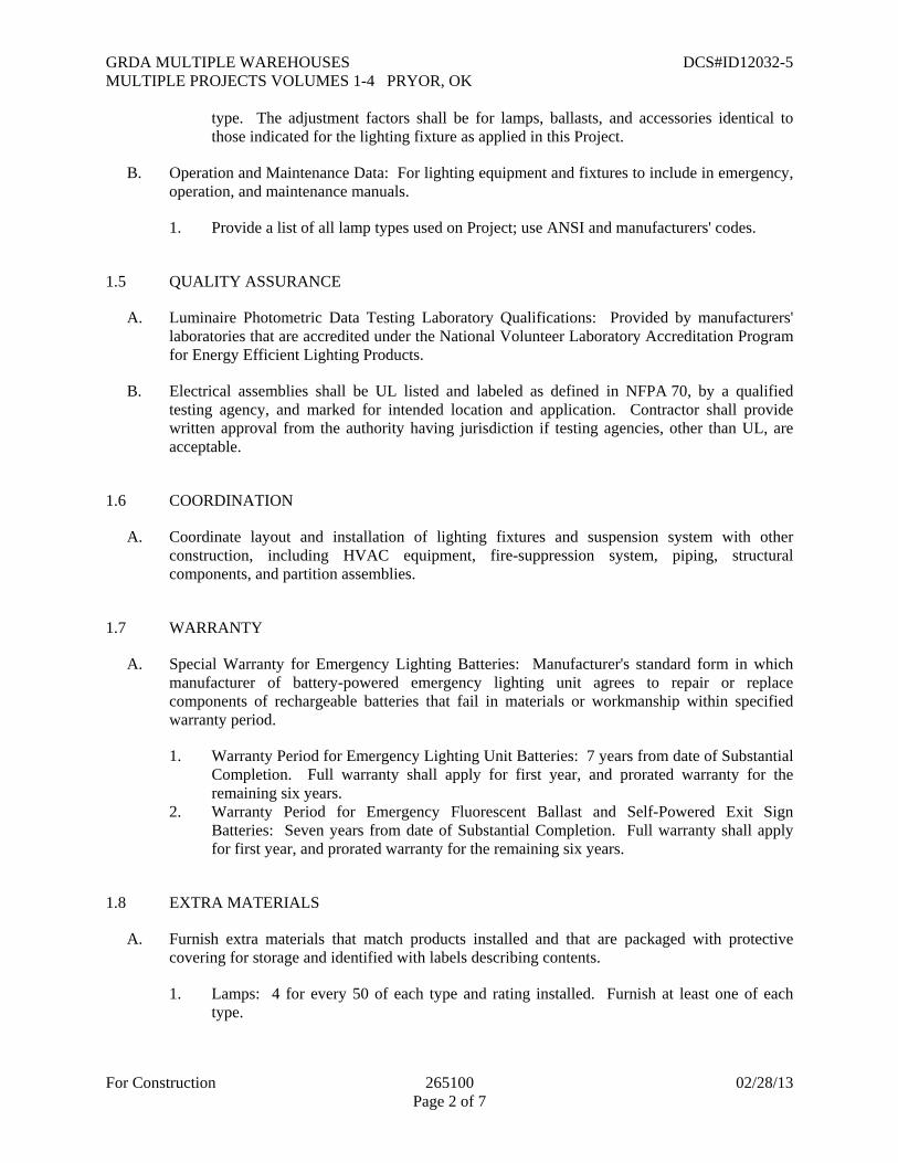
GRDA MULTIPLE WAREHOUSES DCS#ID12032-5 MULTIPLE PROJECTS VOLUMES 1-4 PRYOR, OK
For Construction 265100 02/28/13 Page 2 of 7
type. The adjustment factors shall be for lamps, ballasts, and accessories identical to those indicated for the lighting fixture as applied in this Project.
B. Operation and Maintenance Data: For lighting equipment and fixtures to include in emergency, operation, and maintenance manuals.
1. Provide a list of all lamp types used on Project; use ANSI and manufacturers' codes.
1.5 QUALITY ASSURANCE
A. Luminaire Photometric Data Testing Laboratory Qualifications: Provided by manufacturers' laboratories that are accredited under the National Volunteer Laboratory Accreditation Program for Energy Efficient Lighting Products.
B. Electrical assemblies shall be UL listed and labeled as defined in NFPA 70, by a qualified testing agency, and marked for intended location and application. Contractor shall provide written approval from the authority having jurisdiction if testing agencies, other than UL, are acceptable.
1.6 COORDINATION
A. Coordinate layout and installation of lighting fixtures and suspension system with other construction, including HVAC equipment, fire-suppression system, piping, structural components, and partition assemblies.
1.7 WARRANTY
A. Special Warranty for Emergency Lighting Batteries: Manufacturer's standard form in which manufacturer of battery-powered emergency lighting unit agrees to repair or replace components of rechargeable batteries that fail in materials or workmanship within specified warranty period.
1. Warranty Period for Emergency Lighting Unit Batteries: 7 years from date of Substantial Completion. Full warranty shall apply for first year, and prorated warranty for the remaining six years.
2. Warranty Period for Emergency Fluorescent Ballast and Self-Powered Exit Sign Batteries: Seven years from date of Substantial Completion. Full warranty shall apply for first year, and prorated warranty for the remaining six years.
1.8 EXTRA MATERIALS
A. Furnish extra materials that match products installed and that are packaged with protective covering for storage and identified with labels describing contents.
1. Lamps: 4 for every 50 of each type and rating installed. Furnish at least one of each type.

GRDA MULTIPLE WAREHOUSES DCS#ID12032-5 MULTIPLE PROJECTS VOLUMES 1-4 PRYOR, OK
For Construction 265100 02/28/13 Page 3 of 7
PART 2 - PRODUCTS
2.1 MANUFACTURERS
A. Products: Subject to compliance with requirements, provide product indicated on Drawings.
2.2 GENERAL REQUIREMENTS FOR LIGHTING FIXTURES AND COMPONENTS
A. Recessed Fixtures: Comply with NEMA LE 4 for ceiling compatibility for recessed fixtures.
B. Fluorescent Fixtures: Comply with UL 1598. Where LER is specified, test according to NEMA LE 5 and NEMA LE 5A as applicable.
C. Metal Parts: Free of burrs and sharp corners and edges.
D. Sheet Metal Components: Steel unless otherwise indicated. Form and support to prevent warping and sagging.
E. Doors, Frames, and Other Internal Access: Smooth operating, free of light leakage under operating conditions, and designed to permit relamping without use of tools. Designed to prevent doors, frames, lenses, diffusers, and other components from falling accidentally during relamping and when secured in operating position.
F. Diffusers and Globes:
1. Acrylic Lighting Diffusers: 100 percent virgin acrylic plastic. High resistance to yellowing and other changes due to aging, exposure to heat, and UV radiation.
a. Lens Thickness: At least 0.125 inch minimum unless otherwise indicated. b. UV stabilized.
G. Factory-Applied Labels: Comply with UL 1598. Include recommended lamps and ballasts. Labels shall be located where they will be readily visible to service personnel, but not seen from normal viewing angles when lamps are in place.
1. Label shall include the following lamp and ballast characteristics:
a. "USE ONLY" and include specific lamp type. b. Lamp diameter code (T-5, T-8, T-12, etc.), tube configuration (twin, quad, triple,
etc.), base type, and nominal wattage for fluorescent and compact fluorescent luminaires.
c. Lamp type, wattage, bulb type (ED17, BD56, etc.) and coating (clear or coated) for HID luminaires.
d. Start type (preheat, rapid start, instant start, etc.) for fluorescent and compact fluorescent luminaires.
e. ANSI ballast type (M98, M57, etc.) for HID luminaires. f. CCT and CRI for all luminaires.

GRDA MULTIPLE WAREHOUSES DCS#ID12032-5 MULTIPLE PROJECTS VOLUMES 1-4 PRYOR, OK
For Construction 265100 02/28/13 Page 4 of 7
2.3 BALLASTS FOR LINEAR FLUORESCENT LAMPS
A. General Requirements for Electronic Ballasts:
1. Fixture ballasts shall be instant-start, unless otherwise noted. 2. Comply with UL 935 and with ANSI C82.11. 3. Designed for type and quantity of lamps served. 4. Ballasts shall be designed for full light output unless another BF, dimmer, or bi-level
control is indicated. 5. Sound Rating: Class A 6. Total Harmonic Distortion Rating: Less than 10 percent. 7. Transient Voltage Protection: IEEE C62.41.1 and IEEE C62.41.2, Category A or better. 8. Operating Frequency: 42 kHz or higher. 9. Lamp Current Crest Factor: 1.7 or less. 10. BF: 0.87 or higher. 11. Power Factor: 0.98 or higher.
B. Luminaires controlled by occupancy sensors shall have programmed-start ballasts.
C. Electronic Programmed-Start Ballasts for T8, T5 and T5HO Lamps: Comply with ANSI C82.11 and the following:
1. Lamp end-of-life detection and shutdown circuit for T5 diameter lamps. 2. Automatic lamp starting after lamp replacement.
D. Single Ballasts for Multiple Lighting Fixtures: Factory wired with ballast arrangements and bundled extension wiring to suit final installation conditions without modification or rewiring in the field.
E. Ballasts for Low-Temperature Environments:
1. Temperatures 0 Deg F: electromagnetic type rated for 0 deg F starting and operating temperature with indicated lamp types.
2. Temperatures Minus 20 Deg F and Higher: Electromagnetic type designed for use with indicated lamp types.
2.4 EXIT SIGNS
A. General Requirements for Exit Signs: Comply with UL 924; for sign colors, visibility, luminance, and lettering size, comply with authorities having jurisdiction.
B. Internally Lighted Signs: 1. Lamps for AC Operation: LEDs, 50,000 hours minimum rated lamp life. 2. Self-Powered Exit Signs (Battery Type): Integral automatic charger in a self-contained
power pack.
a. Battery: Sealed, maintenance-free, nickel-cadmium type. b. Charger: Fully automatic, solid-state type with sealed transfer relay. c. Operation: Relay automatically energizes lamp from battery when circuit voltage
drops to 80 percent of nominal voltage or below. When normal voltage is restored,

GRDA MULTIPLE WAREHOUSES DCS#ID12032-5 MULTIPLE PROJECTS VOLUMES 1-4 PRYOR, OK
For Construction 265100 02/28/13 Page 5 of 7
relay disconnects lamps from battery, and battery is automatically recharged and floated on charger.
d. Test Push Button: Push-to-test type, in unit housing, simulates loss of normal power and demonstrates unit operability.
e. LED Indicator Light: Indicates normal power on. Normal glow indicates trickle charge; bright glow indicates charging at end of discharge cycle.
2.5 EMERGENCY LIGHTING UNITS
A. General Requirements for Emergency Lighting Units: Self-contained units complying with UL 924.
1. Battery: Sealed, maintenance-free, lead-acid type, unless otherwise indicated on the drawings.
2. Charger: Fully automatic, solid-state type with sealed transfer relay. 3. Operation: Relay automatically turns lamp on when power-supply circuit voltage drops
to 80 percent of nominal voltage or below. Lamp automatically disconnects from battery when voltage approaches deep-discharge level. When normal voltage is restored, relay disconnects lamps from battery, and battery is automatically recharged and floated on charger.
4. Test Push Button: Push-to-test type, in unit housing, simulates loss of normal power and demonstrates unit operability.
5. LED Indicator Light: Indicates normal power on. Normal glow indicates trickle charge; bright glow indicates charging at end of discharge cycle.
6. Wire Guard: Heavy-chrome-plated wire guard protects lamp heads or fixtures. 7. Integral Time-Delay Relay: Holds unit on for fixed interval of 15 minutes when power is
restored after an outage. 8. Integral Self-Test: Factory-installed electronic device automatically initiates code-
required test of unit emergency operation at required intervals. Test failure is annunciated by an integral audible alarm and a flashing red LED.
2.6 FLUORESCENT LAMPS
A. Fluorescent lamps shall be low mercury when available for the type of lamps/luminaries indicated on the Fixture Schedule.
2.7 LIGHTING FIXTURE SUPPORT COMPONENTS
A. Comply with Division 26 Section "Hangers and Supports for Electrical Systems" for channel- and angle-iron supports and nonmetallic channel and angle supports.
B. Single-Stem Hangers: 1/2-inch steel tubing with swivel ball fittings and ceiling canopy. Finish same as fixture.
C. Twin-Stem Hangers: Two, 1/2-inch steel tubes with single canopy designed to mount a single fixture. Finish same as fixture.
D. Wires: ASTM A 641/A 641M, Class 3, soft temper, zinc-coated steel, 12 gage.

GRDA MULTIPLE WAREHOUSES DCS#ID12032-5 MULTIPLE PROJECTS VOLUMES 1-4 PRYOR, OK
For Construction 265100 02/28/13 Page 6 of 7
E. Wires for Humid Spaces: ASTM A 580/A 580M, Composition 302 or 304, annealed stainless steel, 12 gage.
F. Rod Hangers: 3/16-inch minimum diameter, cadmium-plated, threaded steel rod.
G. Hook Hangers: Integrated assembly matched to fixture and line voltage and equipped with threaded attachment, cord, and locking-type plug.
PART 3 - EXECUTION
3.1 INSTALLATION
A. Lighting fixtures:
1. Set level, plumb, and square with ceilings and walls unless otherwise indicated. 2. Install lamps in each luminaire. 3. Cut-out holes in ceiling shall be sized based on the manufacturer’s recommendations.
B. Remote Mounting of Ballasts: Distance between the ballast and fixture shall not exceed that recommended by ballast manufacturer. Verify, with ballast manufacturers, maximum distance between ballast and luminaire.
C. Suspended Lighting Fixture Support:
1. Pendants and Rods: Where longer than 48 inches, brace to limit swinging. 2. Stem-Mounted, Single-Unit Fixtures: Suspend with twin-stem hangers. 3. Continuous Rows: Use tubing or stem for wiring at one point and tubing or rod for
suspension for each unit length of fixture chassis, including one at each end. 4. Do not use grid as support for pendant luminaires. Connect support wires or rods to
building structure.
D. Connect wiring according to Division 26 Section "Low-Voltage Electrical Power Conductors and Cables."
3.2 IDENTIFICATION
A. Install labels with panel and circuit numbers on concealed junction and outlet boxes. Comply with requirements for identification specified in Division 26 Section "Identification for Electrical Systems."
3.3 FIELD QUALITY CONTROL
A. Test for Emergency Lighting: Interrupt power supply to demonstrate proper operation. Verify transfer from normal power to battery and retransfer to normal.
B. Verify that self-luminous exit signs are installed according to their listing and the requirements in NFPA 101.

GRDA MULTIPLE WAREHOUSES DCS#ID12032-5 MULTIPLE PROJECTS VOLUMES 1-4 PRYOR, OK
For Construction 265100 02/28/13 Page 7 of 7
END OF SECTION 265100


GRDA MULTIPLE WAREHOUSES DCS#ID12032-5 MULTIPLE PROJECTS VOLUMES 1-4 PRYOR, OK
For Construction 000107 02/28/13 Page 1 of 4
SECTION 311000 - SITE CLEARING
PART 1 - GENERAL
1.1 SUMMARY
A. Section Includes:
1. Protecting existing vegetation to remain. 2. Removing existing vegetation. 3. Clearing and grubbing. 4. Stripping and stockpiling topsoil. 5. Removing above- and below-grade site improvements. 6. Disconnecting, capping or sealing site utilities. 7. Temporary erosion- and sedimentation-control measures.
1.2 MATERIAL OWNERSHIP
A. Except for stripped topsoil and other materials indicated to be stockpiled or otherwise remain Owner's property, cleared materials shall become Contractor's property and shall be removed from Project site.
1.3 PROJECT CONDITIONS
A. Traffic: Minimize interference with adjoining roads, streets, walks, and other adjacent occupied or used facilities during site-clearing operations.
1. Do not close or obstruct streets, walks, or other adjacent occupied or used facilities without permission from Owner and authorities having jurisdiction.
2. Provide alternate routes around closed or obstructed traffic ways if required by Owner or authorities having jurisdiction.
B. Salvable Improvements: Carefully remove items indicated to be salvaged and store on Owner's premises where indicated.
C. Utility Locator Service: Notify utility locator service for area where Project is located before site clearing.
D. Do not commence site clearing operations until temporary erosion- and sedimentation-control and plant-protection measures are in place.
E. The following practices are prohibited within protection zones:
1. Storage of construction materials, debris, or excavated material. 2. Parking vehicles or equipment. 3. Foot traffic. 4. Erection of sheds or structures.

GRDA MULTIPLE WAREHOUSES DCS#ID12032-5 MULTIPLE PROJECTS VOLUMES 1-4 PRYOR, OK
For Construction 000107 02/28/13 Page 2 of 4
5. Impoundment of water. 6. Excavation or other digging unless otherwise indicated. 7. Attachment of signs to or wrapping materials around trees or plants unless otherwise
indicated.
PART 2 - PRODUCTS
2.1 MATERIALS
A. Satisfactory Soil Material: Requirements for satisfactory soil material are specified in Division 31 Section "Earth Moving."
1. Obtain approved borrow soil material off-site when satisfactory soil material is not available on-site.
PART 3 - EXECUTION
3.1 PREPARATION
A. Protect and maintain benchmarks and survey control points from disturbance during construction.
B. Locate and clearly identify trees, shrubs, and other vegetation to remain or to be relocated.
C. Protect existing site improvements to remain from damage during construction.
1. Restore damaged improvements to their original condition, as acceptable to Owner.
3.2 TEMPORARY EROSION AND SEDIMENTATION CONTROL
A. Provide temporary erosion- and sedimentation-control measures to prevent soil erosion and discharge of soil-bearing water runoff or airborne dust to adjacent properties and walkways, according to erosion- and sedimentation-control Drawings and requirements of authorities having jurisdiction.
B. Verify that flows of water redirected from construction areas or generated by construction activity do not enter or cross protection zones.
C. Inspect, maintain, and repair erosion- and sedimentation-control measures during construction until permanent vegetation has been established.
D. Remove erosion and sedimentation controls and restore and stabilize areas disturbed during removal.

GRDA MULTIPLE WAREHOUSES DCS#ID12032-5 MULTIPLE PROJECTS VOLUMES 1-4 PRYOR, OK
For Construction 000107 02/28/13 Page 3 of 4
3.3 TREE AND PLANT PROTECTION
A. General: Protect trees and plants remaining on-site according to requirements in Division 01 Section "Temporary Tree and Plant Protection."
B. Repair or replace trees, shrubs, and other vegetation indicated to remain or be relocated that are damaged by construction operations, in a manner approved by Architect.
3.4 EXISTING UTILITIES
A. Locate, identify, disconnect, and seal or cap utilities indicated to be removed or abandoned in place.
1. Arrange with utility companies to shut off indicated utilities.
B. Interrupting Existing Utilities: Do not interrupt utilities serving facilities occupied by Owner or others unless permitted under the following conditions and then only after arranging to provide temporary utility services according to requirements indicated:
1. Notify Architect not less than two days in advance of proposed utility interruptions. 2. Do not proceed with utility interruptions without Architect's written permission.
3.5 CLEARING AND GRUBBING
A. Remove obstructions, trees, shrubs, and other vegetation to permit installation of new construction.
1. Grind down stumps and remove roots, obstructions, and debris to a depth of 18 inches below exposed subgrade.
2. Use only hand methods for grubbing within protection zones.
B. Fill depressions caused by clearing and grubbing operations with satisfactory soil material unless further excavation or earthwork is indicated.
1. Place fill material in horizontal layers not exceeding a loose depth of 8 inches, and compact each layer to a density equal to adjacent original ground.
3.6 TOPSOIL STRIPPING
A. Remove sod and grass before stripping topsoil.
B. Strip topsoil to depth of 4 inches in a manner to prevent intermingling with underlying subsoil or other waste materials.
C. Stockpile topsoil away from edge of excavations without intermixing with subsoil. Grade and shape stockpiles to drain surface water. Cover to prevent windblown dust and erosion by water.

GRDA MULTIPLE WAREHOUSES DCS#ID12032-5 MULTIPLE PROJECTS VOLUMES 1-4 PRYOR, OK
For Construction 000107 02/28/13 Page 4 of 4
3.7 SITE IMPROVEMENTS
A. Remove existing above- and below-grade improvements as indicated and necessary to facilitate new construction.
3.8 DISPOSAL OF SURPLUS AND WASTE MATERIALS
A. Remove surplus soil material, unsuitable topsoil, obstructions, demolished materials, and waste materials including trash and debris, and legally dispose of them off Owner's property.
B. Separate recyclable materials produced during site clearing from other nonrecyclable materials. Store or stockpile without intermixing with other materials and transport them to recycling facilities. Do not interfere with other Project work.
END OF SECTION 311000
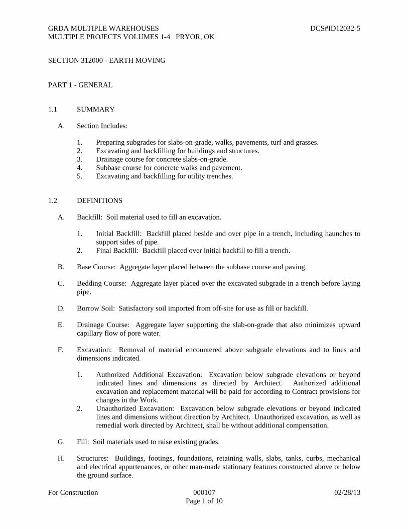
GRDA MULTIPLE WAREHOUSES DCS#ID12032-5 MULTIPLE PROJECTS VOLUMES 1-4 PRYOR, OK
For Construction 000107 02/28/13 Page 1 of 10
SECTION 312000 - EARTH MOVING
PART 1 - GENERAL
1.1 SUMMARY
A. Section Includes:
1. Preparing subgrades for slabs-on-grade, walks, pavements, turf and grasses. 2. Excavating and backfilling for buildings and structures. 3. Drainage course for concrete slabs-on-grade. 4. Subbase course for concrete walks and pavement. 5. Excavating and backfilling for utility trenches.
1.2 DEFINITIONS
A. Backfill: Soil material used to fill an excavation.
1. Initial Backfill: Backfill placed beside and over pipe in a trench, including haunches to support sides of pipe.
2. Final Backfill: Backfill placed over initial backfill to fill a trench.
B. Base Course: Aggregate layer placed between the subbase course and paving.
C. Bedding Course: Aggregate layer placed over the excavated subgrade in a trench before laying pipe.
D. Borrow Soil: Satisfactory soil imported from off-site for use as fill or backfill.
E. Drainage Course: Aggregate layer supporting the slab-on-grade that also minimizes upward capillary flow of pore water.
F. Excavation: Removal of material encountered above subgrade elevations and to lines and dimensions indicated.
1. Authorized Additional Excavation: Excavation below subgrade elevations or beyond indicated lines and dimensions as directed by Architect. Authorized additional excavation and replacement material will be paid for according to Contract provisions for changes in the Work.
2. Unauthorized Excavation: Excavation below subgrade elevations or beyond indicated lines and dimensions without direction by Architect. Unauthorized excavation, as well as remedial work directed by Architect, shall be without additional compensation.
G. Fill: Soil materials used to raise existing grades.
H. Structures: Buildings, footings, foundations, retaining walls, slabs, tanks, curbs, mechanical and electrical appurtenances, or other man-made stationary features constructed above or below the ground surface.

GRDA MULTIPLE WAREHOUSES DCS#ID12032-5 MULTIPLE PROJECTS VOLUMES 1-4 PRYOR, OK
For Construction 000107 02/28/13 Page 2 of 10
I. Subbase Course: Aggregate layer placed between the subgrade and base course for hot-mix asphalt pavement, or aggregate layer placed between the subgrade and a cement concrete pavement or a cement concrete or hot-mix asphalt walk.
J. Subgrade: Uppermost surface of an excavation or the top surface of a fill or backfill immediately below subbase, drainage fill, drainage course, or topsoil materials.
K. Utilities: On-site underground pipes, conduits, ducts, and cables, as well as underground services within buildings.
1.3 QUALITY ASSURANCE
A. Geotechnical Testing Agency Qualifications: Qualified according to ASTM E 329 and ASTM D 3740 for testing indicated.
1.4 PROJECT CONDITIONS
A. Traffic: Minimize interference with adjoining roads, streets, walks, and other adjacent occupied or used facilities during earth moving operations.
1. Do not close or obstruct streets, walks, or other adjacent occupied or used facilities without permission from Owner and authorities having jurisdiction.
2. Provide alternate routes around closed or obstructed traffic ways if required by Owner or authorities having jurisdiction.
B. Utility Locator Service: Notify utility locator service for area where Project is located before beginning earth moving operations.
C. Do not commence earth moving operations until temporary tree-protection measures in are in place. Refer to construction documents.
D. Do not commence earth moving operations until temporary erosion- and sedimentation-control measures are in place. Refer to construction documents.
PART 2 - PRODUCTS
2.1 SOIL MATERIALS
A. General: Provide borrow soil materials when sufficient satisfactory soil materials are not available from excavations.
Satisfactory Soils: Soil Classification Groups GW, GP, GM, SW, SP, and SM according to ASTM D 2487 Groups A-1, A-2-4, A-2-5, and A-3 according to AASHTO M 145, or a combination of these groups; free of rock or gravel larger than 2 inches in any dimension, debris, waste, frozen materials, vegetation, and other deleterious matter.
1. Liquid Limit: as given in the Geotechnical Report.

GRDA MULTIPLE WAREHOUSES DCS#ID12032-5 MULTIPLE PROJECTS VOLUMES 1-4 PRYOR, OK
For Construction 000107 02/28/13 Page 3 of 10
2. Plasticity Index: as given in the Geotechnical Report.
B. Unsatisfactory Soils: Soil Classification Groups GC, SC, CL, ML, OL, CH, MH, OH, and PT according to ASTM D 2487 Groups A-2-6, A-2-7, A-4, A-5, A-6, and A-7 according to AASHTO M 145, or a combination of these groups.
1. Unsatisfactory soils also include satisfactory soils not maintained within 2 percent of optimum moisture content at time of compaction.
C. Subbase Material: Naturally or artificially graded mixture of natural or crushed gravel, crushed stone, and natural or crushed sand; ASTM D 2940; with at least 90 percent passing a 1-1/2-inch sieve and not more than 12 percent passing a No. 200 sieve.
D. Base Course: Naturally or artificially graded mixture of natural or crushed gravel, crushed stone, and natural or crushed sand; ASTM D 2940; with at least 95 percent passing a 1-1/2-inch sieve and not more than 8 percent passing a No. 200 sieve.
E. Engineered Fill: Naturally or artificially graded mixture of natural or crushed gravel, crushed stone, and natural or crushed sand; ASTM D 2940; with at least 90 percent passing a 1-1/2-inch sieve and not more than 12 percent passing a No. 200 sieve.
F. Bedding Course: Naturally or artificially graded mixture of natural or crushed gravel, crushed stone, and natural or crushed sand; ASTM D 2940; except with 100 percent passing a 1-inch sieve and not more than 8 percent passing a No. 200 sieve.
G. Drainage Course: Narrowly graded mixture of washed crushed stone, or crushed or uncrushed gravel; ASTM D 448; coarse-aggregate grading Size 57; with 100 percent passing a 1-1/2-inch sieve and 0 to 5 percent passing a No. 8 sieve.
2.2 ACCESSORIES
A. Warning Tape: Acid- and alkali-resistant, polyethylene film warning tape manufactured for marking and identifying underground utilities, 6 inches wide and 4 mils thick, continuously inscribed with a description of the utility; colored to comply with local practice or requirements of authorities having jurisdiction.
B. Detectable Warning Tape: Acid- and alkali-resistant, polyethylene film warning tape manufactured for marking and identifying underground utilities, a minimum of 6 inches wide and 4 mils thick, continuously inscribed with a description of the utility, with metallic core encased in a protective jacket for corrosion protection, detectable by metal detector when tape is buried up to 30 inches deep; colored to comply with local practice or requirements of authorities having jurisdiction.

GRDA MULTIPLE WAREHOUSES DCS#ID12032-5 MULTIPLE PROJECTS VOLUMES 1-4 PRYOR, OK
For Construction 000107 02/28/13 Page 4 of 10
PART 3 - EXECUTION
3.1 PREPARATION
A. Protect structures, utilities, sidewalks, pavements, and other facilities from damage caused by settlement, lateral movement, undermining, washout, and other hazards created by earth moving operations.
B. Protect and maintain erosion and sedimentation controls during earth moving operations.
C. Protect subgrades and foundation soils from freezing temperatures and frost. Remove temporary protection before placing subsequent materials.
3.2 EXCAVATION, GENERAL
A. Unclassified Excavation: Excavate to subgrade elevations regardless of the character of surface and subsurface conditions encountered. Unclassified excavated materials may include rock, soil materials, and obstructions. No changes in the Contract Sum or the Contract Time will be authorized for rock excavation or removal of obstructions.
1. If excavated materials intended for fill and backfill include unsatisfactory soil materials and rock, replace with satisfactory soil materials.
3.3 EXCAVATION FOR STRUCTURES
A. Excavate to indicated elevations and dimensions within a tolerance of plus or minus 1 inch. If applicable, extend excavations a sufficient distance from structures for placing and removing concrete formwork, for installing services and other construction, and for inspections.
1. Excavations for Footings and Foundations: Do not disturb bottom of excavation. Excavate by hand to final grade just before placing concrete reinforcement. Trim bottoms to required lines and grades to leave solid base to receive other work.
3.4 EXCAVATION FOR WALKS AND PAVEMENTS
A. Excavate surfaces under walks and pavements to indicated lines, cross sections, elevations, and subgrades.
3.5 EXCAVATION FOR UTILITY TRENCHES
A. Excavate trenches to indicated gradients, lines, depths, and elevations.
B. Excavate trenches to uniform widths to provide the following clearance on each side of pipe or conduit. Excavate trench walls vertically from trench bottom to 12 inches higher than top of pipe or conduit unless otherwise indicated.
1. Clearance: 6 inches each side of pipe or conduit.
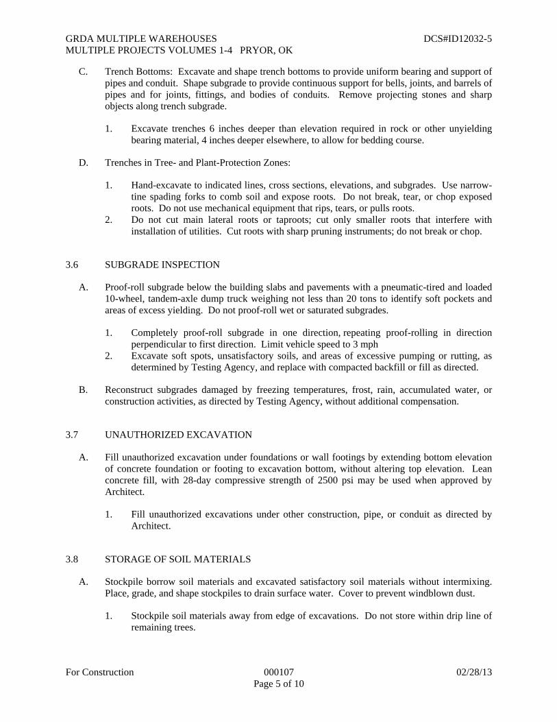
GRDA MULTIPLE WAREHOUSES DCS#ID12032-5 MULTIPLE PROJECTS VOLUMES 1-4 PRYOR, OK
For Construction 000107 02/28/13 Page 5 of 10
C. Trench Bottoms: Excavate and shape trench bottoms to provide uniform bearing and support of pipes and conduit. Shape subgrade to provide continuous support for bells, joints, and barrels of pipes and for joints, fittings, and bodies of conduits. Remove projecting stones and sharp objects along trench subgrade.
1. Excavate trenches 6 inches deeper than elevation required in rock or other unyielding bearing material, 4 inches deeper elsewhere, to allow for bedding course.
D. Trenches in Tree- and Plant-Protection Zones:
1. Hand-excavate to indicated lines, cross sections, elevations, and subgrades. Use narrow-tine spading forks to comb soil and expose roots. Do not break, tear, or chop exposed roots. Do not use mechanical equipment that rips, tears, or pulls roots.
2. Do not cut main lateral roots or taproots; cut only smaller roots that interfere with installation of utilities. Cut roots with sharp pruning instruments; do not break or chop.
3.6 SUBGRADE INSPECTION
A. Proof-roll subgrade below the building slabs and pavements with a pneumatic-tired and loaded 10-wheel, tandem-axle dump truck weighing not less than 20 tons to identify soft pockets and areas of excess yielding. Do not proof-roll wet or saturated subgrades.
1. Completely proof-roll subgrade in one direction, repeating proof-rolling in direction perpendicular to first direction. Limit vehicle speed to 3 mph
2. Excavate soft spots, unsatisfactory soils, and areas of excessive pumping or rutting, as determined by Testing Agency, and replace with compacted backfill or fill as directed.
B. Reconstruct subgrades damaged by freezing temperatures, frost, rain, accumulated water, or construction activities, as directed by Testing Agency, without additional compensation.
3.7 UNAUTHORIZED EXCAVATION
A. Fill unauthorized excavation under foundations or wall footings by extending bottom elevation of concrete foundation or footing to excavation bottom, without altering top elevation. Lean concrete fill, with 28-day compressive strength of 2500 psi may be used when approved by Architect.
1. Fill unauthorized excavations under other construction, pipe, or conduit as directed by Architect.
3.8 STORAGE OF SOIL MATERIALS
A. Stockpile borrow soil materials and excavated satisfactory soil materials without intermixing. Place, grade, and shape stockpiles to drain surface water. Cover to prevent windblown dust.
1. Stockpile soil materials away from edge of excavations. Do not store within drip line of remaining trees.

GRDA MULTIPLE WAREHOUSES DCS#ID12032-5 MULTIPLE PROJECTS VOLUMES 1-4 PRYOR, OK
For Construction 000107 02/28/13 Page 6 of 10
3.9 BACKFILL
A. Place and compact backfill in excavations promptly, but not before completing the following:
1. Construction below finish grade including, where applicable, subdrainage, dampproofing, waterproofing, and perimeter insulation.
2. Surveying locations of underground utilities for Record Documents. 3. Testing and inspecting underground utilities. 4. Removing concrete formwork. 5. Removing trash and debris. 6. Removing temporary shoring and bracing, and sheeting. 7. Installing permanent or temporary horizontal bracing on horizontally supported walls.
B. Place backfill on subgrades free of mud, frost, snow, or ice.
3.10 UTILITY TRENCH BACKFILL
A. Place backfill on subgrades free of mud, frost, snow, or ice.
B. Place and compact bedding course on trench bottoms and where indicated. Shape bedding course to provide continuous support for bells, joints, and barrels of pipes and for joints, fittings, and bodies of conduits.
C. Trenches under Footings: Backfill trenches excavated under footings and within 18 inches of bottom of footings with satisfactory soil; fill with concrete to elevation of bottom of footings. Concrete is specified in Division 03 Section "Cast-in-Place Concrete."
D. Backfill voids with satisfactory soil while removing shoring and bracing.
E. Place and compact final backfill of satisfactory soil to final subgrade elevation.
F. Install warning tape directly above utilities, 12 inches below finished grade, except 6 inches below subgrade under pavements and slabs.
3.11 SOIL FILL
A. Plow, scarify, bench, or break up sloped surfaces steeper than 1 vertical to 4 horizontal so fill material will bond with existing material.
B. Place and compact fill material in layers to required elevations as follows:
1. Under grass and planted areas, use satisfactory soil material. 2. Under walks and pavements, use satisfactory soil material. 3. Under steps and ramps, use engineered fill. 4. Under building slabs, use engineered fill. 5. Under footings and foundations, use engineered fill.

GRDA MULTIPLE WAREHOUSES DCS#ID12032-5 MULTIPLE PROJECTS VOLUMES 1-4 PRYOR, OK
For Construction 000107 02/28/13 Page 7 of 10
3.12 SOIL MOISTURE CONTROL
A. Uniformly moisten or aerate subgrade and each subsequent fill or backfill soil layer before compaction to within 2 percent of optimum moisture content.
1. Do not place backfill or fill soil material on surfaces that are muddy, frozen, or contain frost or ice.
2. Remove and replace, or scarify and air dry, otherwise satisfactory soil material that exceeds optimum moisture content by 2 percent and is too wet to compact to specified dry unit weight.
3.13 COMPACTION OF SOIL BACKFILLS AND FILLS
A. Place backfill and fill soil materials in layers not more than 8 inches in loose depth for material compacted by heavy compaction equipment, and not more than 4 inches in loose depth for material compacted by hand-operated tampers.
B. Place backfill and fill soil materials evenly on all sides of structures to required elevations, and uniformly along the full length of each structure.
C. Compact soil materials to not less than the following percentages of maximum dry unit weight according to ASTM D 698:
1. Under structures, building slabs, steps, and pavements, scarify and recompact top 12 inches of existing subgrade and each layer of backfill or fill soil material at 95 percent.
2. Under walkways, scarify and recompact top 6 inches below subgrade and compact each layer of backfill or fill soil material at 92 percent.
3. Under turf or unpaved areas, scarify and recompact top 6 inches below subgrade and compact each layer of backfill or fill soil material at 85 percent.
4. For utility trenches, compact each layer of initial and final backfill soil material at 85 percent.
3.14 GRADING
A. General: Uniformly grade areas to a smooth surface, free of irregular surface changes. Comply with compaction requirements and grade to cross sections, lines, and elevations indicated.
1. Provide a smooth transition between adjacent existing grades and new grades. 2. Cut out soft spots, fill low spots, and trim high spots to comply with required surface
tolerances.
B. Site Rough Grading: Slope grades to direct water away from buildings and to prevent ponding. Finish subgrades to required elevations within the following tolerances:
1. Turf or Unpaved Areas: Plus or minus 1 inch 2. Walks: Plus or minus 1 inch. 3. Pavements: Plus or minus 1/2 inch.

GRDA MULTIPLE WAREHOUSES DCS#ID12032-5 MULTIPLE PROJECTS VOLUMES 1-4 PRYOR, OK
For Construction 000107 02/28/13 Page 8 of 10
C. Grading inside Building Lines: Finish subgrade to a tolerance of 1/2 inch when tested with a 10-foot straightedge.
3.15 SUBSURFACE DRAINAGE
A. Subdrainage Pipe: Specified in Division 33 Section "Subdrainage."
B. Subsurface Drain: Place subsurface drainage geotextile around perimeter of subdrainage trench. Place a 6-inch course of filter material on subsurface drainage geotextile to support subdrainage pipe. Encase subdrainage pipe in a minimum of 12 inches of filter material, placed in compacted layers 6 inches thick, and wrap in subsurface drainage geotextile, overlapping sides and ends at least 6 inches
C. Drainage Backfill: Place and compact filter material over subsurface drain, in width indicated, to within 12 inches of final subgrade, in compacted layers 6 inches thick. Overlay drainage backfill with one layer of subsurface drainage geotextile, overlapping sides and ends at least 6 inches
3.16 SUBBASE AND BASE COURSES UNDER PAVEMENTS AND WALKS
A. Place subbase course and base course on subgrades free of mud, frost, snow, or ice.
B. On prepared subgrade, place subbase course and base course under pavements and walks as follows: 1. Prepared subgrade according with Geotechnical Report. 2. Place subbase course and base course that exceeds 6 inches in compacted thickness in
layers of equal thickness, with no compacted layer more than 6 inches thick or less than 3 inches thick.
3. Compact subbase course and base course at optimum moisture content to required grades, lines, cross sections, and thickness to not less than 95 percent of maximum dry unit weight according to ASTM D 698.
3.17 DRAINAGE COURSE UNDER CONCRETE SLABS-ON-GRADE
A. Place drainage course on subgrades free of mud, frost, snow, or ice.
B. On prepared subgrade, place and compact drainage course under cast-in-place concrete slabs-on-grade as follows:
1. Place drainage course 6 inches or less in compacted thickness in a single layer. 2. Place drainage course that exceeds 6 inches in compacted thickness in layers of equal
thickness, with no compacted layer more than 6 inches thick or less than 3 inches thick.
3.18 FIELD QUALITY CONTROL
A. Testing Agency: Contractor will engage a qualified geotechnical engineering testing agency to perform tests and inspections.

GRDA MULTIPLE WAREHOUSES DCS#ID12032-5 MULTIPLE PROJECTS VOLUMES 1-4 PRYOR, OK
For Construction 000107 02/28/13 Page 9 of 10
B. Allow testing agency to inspect and test subgrades and each fill or backfill layer. Proceed with subsequent earth moving only after test results for previously completed work comply with requirements.
C. Footing Subgrade: At footing subgrades, at least one test of each soil stratum will be performed to verify design bearing capacities. Subsequent verification and approval of other footing subgrades may be based on a visual comparison of subgrade with tested subgrade when approved by Architect.
D. Testing agency will test compaction of soils in place according to ASTM D 1556, ASTM D 2167, ASTM D 2922, and ASTM D 2937, as applicable. Tests will be performed at the following locations and frequencies:
1. Paved and Building Slab Areas: At subgrade and at each compacted fill and backfill layer, at least one test for every 2000 sq. ft. or less of paved area or building slab, but in no case fewer than three tests.
2. Foundation Wall Backfill: At each compacted backfill layer, at least one test for every 100 feet or less of wall length, but no fewer than two tests.
3. Trench Backfill: At each compacted initial and final backfill layer, at least one test for every 150 feet or less of trench length, but no fewer than two tests.
E. When testing agency reports that subgrades, fills, or backfills have not achieved degree of compaction specified, scarify and moisten or aerate, or remove and replace soil materials to depth required; recompact and retest until specified compaction is obtained.
3.19 PROTECTION
A. Protecting Graded Areas: Protect newly graded areas from traffic, freezing, and erosion. Keep free of trash and debris.
B. Repair and reestablish grades to specify tolerances where completed or partially completed surfaces become eroded, rutted, settled, or where they lose compaction due to subsequent construction operations or weather conditions.
1. Scarify or remove and replace soil material to depth as directed by Architect; reshape and recompact.
C. Where settling occurs before Project correction period elapses, remove finished surfacing, backfill with additional soil material, compact, and reconstruct surfacing.
1. Restore appearance, quality, and condition of finished surfacing to match adjacent work, and eliminate evidence of restoration to greatest extent possible.
3.20 DISPOSAL OF SURPLUS AND WASTE MATERIALS
A. Remove surplus satisfactory soil and waste materials, including unsatisfactory soil, trash, and debris, and legally dispose of them off Owner's property.

GRDA MULTIPLE WAREHOUSES DCS#ID12032-5 MULTIPLE PROJECTS VOLUMES 1-4 PRYOR, OK
For Construction 000107 02/28/13 Page 10 of 10
B. Transport surplus satisfactory soil to designated storage areas on Owner's property. Stockpile or spread soil as directed by Architect.
1. Remove waste materials, including unsatisfactory soil, trash, and debris, and legally dispose of them off Owner's property.
END OF SECTION 312000


SUBSURFACE EXPLORATION AND GEOTECHNICAL REPORT GRDA- TRANSMISSION HEADQUARTERS
PRYOR, OKLAHOMA
TABLE OF CONTENTS
SECTION PAGE

1
SUBSURFACE EXPLORATION AND GEOTECHNICAL REPORT
GRDA- TRANSMISSION HEADQUARTERS
PRYOR, OKLAHOMA
INTRODUCTION
This report presents the results of a preliminary subsurface exploration and geotechnical
investigation provided by A&M Engineering and Environmental Services, Inc. (A&M
Engineering) for the Grand River Dam Authority (GRDA) Transmission Headquarters (Site).
The Site is located at 635 HWY 69A in Pryor, Oklahoma. The legal description of the site is a
tract of land located in the N/2 of the NE/4 of Section 3, Township 20 North, Range 19 East,
Mayes County, Oklahoma.
As authorized, eight soil borings were drilled as part of our investigation. This report includes
the results found from these e borings. This report does not reflect possible variations which
may occur across the site. The nature and extent of such variations may not become evident until
construction has begun. If variations appear, it will be necessary to reevaluate the
recommendations of this report. A location map, boring logs and boring location diagram are
included in Appendix A.
The project involves the construction of three metal storage canopies and one new metal building
expansion. The metal canopies and building expansion will be constructed of pre-engineered
structural steel frame with steel panel walls and steel purlin roof. The building expansion will
have a concrete slab on grade floor. We anticipate isolated column and continuous wall loads
will be less than 40 kips and 1 kips per lineal foot, respectively. Floor slab loads will be less than
150 psf. Final grades for the building are not available, but we anticipate only minor cutting or
filling will be needed to develop the final building and pavement subgrade elevations.

2
The purpose of this report is to describe the subsurface conditions encountered in the borings;
analyze the data obtained; and provide recommendations regarding the following:
General site development and subgrade preparation
Foundation depth and peir design, allowable bearing capacity and estimates of
potential settlement
General pavement design criteria and pavement subgrade preparation
Factors that will impact construction and performance of the proposed
construction
SUBSURFACE EXPLORATION PROCEDURES
Mohawk Drilling, Inc. drilled and sampled the exploratory borings for the project on September
27th, 28th
and October 1st 2012. A&M Engineering established the boring locations in the field
by pacing or taping from the available reference features shown on the boring locations diagram.
The borings were drilled with a truck-mounted drill rig using continuous flight augers to advance
the boring. Representative soil samples were obtained using the split-barrel sampling procedure
in accordance with the appropriate ASTM procedure.
Disturbed samples are obtained in the split-barrel sampling procedure by driving a 2-inch O. D.
split-barrel sampler into the ground using a 140-pound CME automatic hammer falling 30
inches. The number of blows required to advance the sampler were recorded in the field and are
shown on the boring logs as the standard penetration resistance (SPT-N) value. The number of
blows required to advance the sampler the final 12 inches or less of a standard 18-inch sampling
interval indicate the in-place relative density of granular soils and, to a lesser degree of accuracy,
the consistency of cohesive soils.
A greater efficiency is achieved with the automatic CME hammer, compared to the conventional
safety hammer operated with a cathead and rope. The effect of this increased efficiency has been
considered in interpreting the standard penetrations resistance values for this project.

3
The soils samples obtained in the field were sealed and returned to our laboratory for further
examination, classification, and testing.
During the drilling operation, an on-site geologist prepared field-boring logs. The logs report the
drilling and sampling methods, sampling intervals, soil and groundwater conditions encountered,
and the geologist’s visual evaluation of the conditions between samples. The final boring logs,
included in this report, have been prepared based on the geologist’s field logs and have been
modified, where appropriate, based on the results of the laboratory observation and testing.
LABORATORY TESTING PROGRAM
Moisture content and, where applicable, calibrated hand penetrometer test were performed on the
split-barrel samples. The calibrated hand penetrometer test provides an indication of the
unconfined compressive strength of a cohesive soil. Also, Atterberg limit tests were performed
on representative samples near the surface. The Atterberg limits indicate the plasticity of
cohesive soils and are used to approximate the soil’s potential for volume change with variation
in moisture content. The laboratory test results are shown on the boring logs.
The soil samples were examined in our laboratory by an experienced geotechnical engineer and
were classified based on the soil’s texture and plasticity in accordance with the General Notes
and Unified Soil Classification System included in Appendix B. The estimated Unified System
group symbols are shown on the boring logs. A brief description of the Unified Soil
Classification System is included in Appendix B.
– SITE AND SUBSURFACE CONDITIONS
The Site is located at 635 HWY 69A in Pryor, Oklahoma. The legal description of the site is a
tract of land located in the N/2 of the NE/4 of Section 3, Township 20 North, Range 19 East,
Mayes County, Oklahoma. Based on the visual inspection and a review of the topographic map
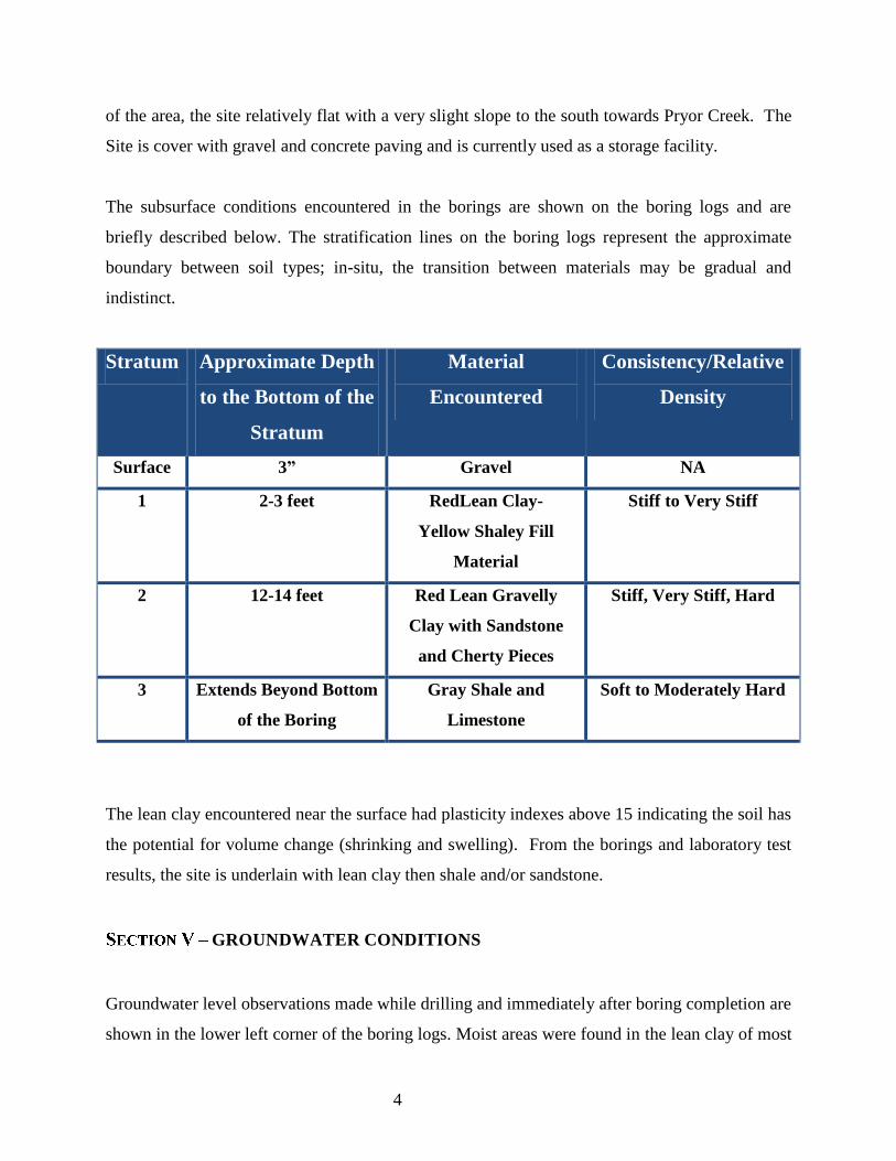
4
of the area, the site relatively flat with a very slight slope to the south towards Pryor Creek. The
Site is cover with gravel and concrete paving and is currently used as a storage facility.
The subsurface conditions encountered in the borings are shown on the boring logs and are
briefly described below. The stratification lines on the boring logs represent the approximate
boundary between soil types; in-situ, the transition between materials may be gradual and
indistinct.
Stratum Approximate Depth
to the Bottom of the
Stratum
Material
Encountered
Consistency/Relative
Density
Surface 3” Gravel NA
1 2-3 feet RedLean Clay-
Yellow Shaley Fill
Material
Stiff to Very Stiff
2 12-14 feet Red Lean Gravelly
Clay with Sandstone
and Cherty Pieces
Stiff, Very Stiff, Hard
3 Extends Beyond Bottom
of the Boring
Gray Shale and
Limestone
Soft to Moderately Hard
The lean clay encountered near the surface had plasticity indexes above 15 indicating the soil has
the potential for volume change (shrinking and swelling). From the borings and laboratory test
results, the site is underlain with lean clay then shale and/or sandstone.
GROUNDWATER CONDITIONS
Groundwater level observations made while drilling and immediately after boring completion are
shown in the lower left corner of the boring logs. Moist areas were found in the lean clay of most
5
of the borings. Groundwater elevations at 24 hours ranged from seven to fourteen feet of the
existing grade. The groundwater elevations show discontinuous zones of perched water may
exist within the clayey material and with any boundary layers between stratums.
The groundwater level observations made during our exploration provide an indication of the
groundwater conditions at the time the boring was performed. Longer monitoring in piezometers
or cased holes would be required to evaluate longer-term groundwater conditions. During some
periods of the year, perched water could develop in the near surface soils. Fluctuations in the
amount of perched water, if any and groundwater levels should be expected throughout the year
depending upon variations in the amount of rainfall, runoff, evaporation, and other hydrological
factors not apparent at the time of our exploration.
ANALYSIS AND RECOMMENDATIONS
Geotechnical Considerations
Based on the existing topography, we anticipate very minor cuts and fills will be required.
Shallow footings can be used to support the proposed building. Recommendations regarding
foundations, slab on grade and other issues related to the geotechnical aspects of the project are
presented in the following sections.
General Site Preparation and Grading
Site preparation within the construction limits should include stripping the existing gravel and
any topsoil.
After stripping and excavating to the proposed subgrade level, the construction area should be
proof-rolled with a tandem axle dump truck or similar rubber tired vehicle. Soils which are
observed to rut or deflect excessively (typically greater than 1 inch) under the moving load (25
ton) should be undercut and recompacted in place or replaced with properly compacted select
fill. The proof-rolling and undercutting activities should be observed by a representative of the
Engineer and should be performed during a period of dry weather.

6
After proof-rolling and correcting soft areas or areas exhibiting rutting or pumping, the subgrade
soils should be scarified to a minimum depth of 8 inches. The moisture content in the scarified
zone should be adjusted to a level at or slightly above the materials optimum moisture content
determined according to the ASTM D 698. The scarified zone should then be compacted to at
least 95 percent of the material’s maximum dry density determined by ASTM D 698.
After subgrade preparation and testing have been completed, select fill placement to establish the
desired design grades should begin. A & M Engineering recommends select fill material be free
of organic or other deleterious material, have a maximum particle size less than 3 inches, and
have a liquid limit less than 35 and a plasticity index of 18 or less and containing at least 15
percent fines. Select fill should be compacted to at least 95 percent of Standard Proctor
maximum dry density as determined by ASTM D698.
Select Fill should be placed in maximum lifts of 8 inches of loose material and should be
compacted within the range of 1 percentage point below to 2 percentage points above the
optimum moisture content value. If water is added, it should be uniformly applied and
thoroughly mixed into the soil by disking or scarifying. Each lift of compacted select fill should
be tested by the Engineer's representative prior to placement of subsequent lifts. The edges of
compacted fill should extend a minimum 5 feet beyond the edges of the building prior to sloping.
The overall performance of the construction will also depend on how well the site drains during
the construction and the life of the structure. Grading of the site around the building should be
accomplished to enable positive drainage away from the building by providing an adequate
gradient. The surface gradient provided will be dependent on the landscaping type and
vegetation. Water infiltration and seepage beneath the floor slabs should be reduced as much as
possible.
Excavation for utility trenches should be performed in accordance with OSHA regulations as
stated in 29 CFR Part 1926. It should be noted that utility trench excavations have the potential
to degrade the properties of the adjacent fill materials. Utility trench walls that are allowed to

7
move laterally can lead to reduced bearing capacity and increased settlement of adjacent
structural elements and overlying slabs.
Backfill for utility trenches is as important as the original subgrade preparation or structural fill
placed to support foundations or slabs. Unless otherwise specified, the backfill for the utility
trenches should be placed in 4 to 6 inch loose lifts and compacted to a minimum of 95% of the
maximum dry density achieved by the Standard Proctor test. The backfill soil’s moisture content
should be adjusted in the range of 1 percentage point below to 2 percentage points above the
optimum moisture content value as determined by the Standard Proctor test. Up to 4 inches of
bedding material placed directly under the pipes or conduits placed in the utility trench can be
compacted to the 90% compaction criteria with respect to Standard Proctor maximum dry
density.
Compaction testing should be performed for every 200 cubic yards of backfill placed or for each
lift within 200 linear feet of trench, whichever is less. Backfill of utility trenches should not be
performed with water standing in the trench. Structural fill should be used as the trench backfill
material.
General
A shallow footing foundation system or a drilled pier foundation can be used to support the
proposed building structures. Detailed recommendations for each foundation type are presented
below.
Drilled Pier Foundations
Straight shaft drilled piers can be used to support the proposed structures. Minimum 18-inch
diameter piers can be used. Piers extending at least two feet or one pier diameter, whichever is
greater, into the gray soft to moderately hard shale or gray hard limestone with shale seams
(bearing material), can be designed using a maximum net allowable total load end bearing
pressure of 30,000 psf. The net allowable bearing pressure refers to the pressure at the

8
foundation bearing level in excess of the minimum surrounding overburden pressure. The
recommended bearing materials were encountered at depths ranging from approximately 13 to
16 feet below the existing grade. The allowable end bearing pressure can be increased by one
third for a short live load condition.
An estimated lateral bearing capacity of 125 psf/f can be used for the gravelly clay and clayey
sand found above the shale bearing unit. Additional pier capacity and resistance to uplift can be
developed by side friction between the cast in place concrete and the surrounding
shale/limestone bedrock. A maximum allowable side friction value of 3,500 psf for uplift or for
downward capacity can be used for that portion of the pier extending more than two feet into the
shale.
Based on the soil and groundwater conditions, temporary casing may be required to complete the
pier installations. A heavy-duty drilling equipped with a rock auger and coring barrel should be
able to penetrate the required depth for bearing. All loose or disturbed material and water should
be removed from pier excavations prior to concrete placement. Concrete should be on site and
ready for placement after each pier excavation is complete.
Shallow Footings
The proposed building can be supported by the native lean stiff to very stiff sandy clay or within
the tested and approved select fill. We recommend using a maximum net allowable bearing
pressure of 2,000 psf. The net allowable bearing pressure is the stress that can be applied at the
base of the footings in excess of the minimum surrounding overburden pressure.
Fill beneath footings should extend laterally beyond all sides of the footings at least 8 inches for
each 12-inch thickness of fill placed below the bearing level. Construction of select fill should
follow the procedures outlined in the “General Site Preparation and Grading” section of this
report.
All exterior footings and footings in non-heated areas should extend at least 24 inches below the
final adjacent grade to provide confinement to the bearing soils and reduce the potential for

9
moisture variation below the bearing level. This depth will also protect the bearing soils against
freezing. Continuous formed footings should have a minimum width of at least 18 inches, and
isolated column footings should have a minimum width of at least 30 inches. Earth formed
trench footings should have a minimum width of at least 16 inches. All footing excavations
should be free of loose soil, debris, and water prior to concrete placement. Concrete should be
placed as soon as possible after excavations are completed to reduce the potential for wetting and
drying of the bearing surface.
Based on the known subsurface conditions and site geology, laboratory testing, anticipated loads
and allowable bearing pressures, properly designed and constructed footings supported on the
recommended materials should experience maximum total and differential settlements of less
than 1 inch and 3/4 inch, respectively.
Seismic Considerations
In general accordance with the 2006 International Building Code (IBC) Site Classification, Table
1613.5.2; the site can be classified as Site Class C. The 2006 IBC requires a site soil profile
determination extending to a depth of 100 feet for seismic site classification. This investigation
deepest boring only extended to 15.8 feet. The seismic site class definition considers that the
shale extends below the maximum depth of the borings in this report.
The site is underlain with moderate plasticity clay subgrade soils; therefore we recommend a low
volume change layer be placed below the floor slab. This layer should be at least 24 inches thick
and should meet the Select Fill material criteria outlined in this report. The Select Fill layer
thickness is in addition to the thickness of any granular leveling material beneath the floor slab.
Based on properly constructing a minimum 24-inch thick select fill layer beneath the floor slab,
we anticipate potential slab movement could be approximately ¾ inch. This magnitude of slab
movement could occur differentially. To further reduce the potential for slab movements, a
greater thickness of select fill could be placed beneath the slab. The existing lean sandy clay
found on-site can be used as fill material under the 24-inch select fill material if properly

10
installed in 8-inch loose lifts and compacted to 95% of the maximum dry density at or above the
optimum moisture.
A vapor retarder should be installed in accordance with ACI 360. The floor slabs should have an
adequate number of joints to reduce cracking resulting from differential movement and
shrinkage.
The floor slab subgrade should be maintained in a relatively moist condition until the floor slab
is constructed. If the subgrade is allowed to dry out, the material should be scarified, moistened
and recompacted prior to the installation of the floor slab.
A&M Engineering recommends that subgrade improvement be accomplished by constructing a
minimum 8-inch thick layer of select fill beneath the pavement section. The on-site subgrade
soils should be over excavated sufficiently to construct a minimum 8-inch thick layer of select
fill below the pavement section. The select fill should meet the criteria previously stated. An
approved crushed aggregate base, crushed limestone screenings, or broken shale may be
considered as the select fill material and, if used, may warrant a slight reduction in the thickness
of select fill required.
Typical, minimum alternative pavement sections are outlined below. The sections are based on a
15 to 20-year traffic life and a subgrade CBR value of 3 for the subgrade. Also, the Light Duty
sections assume that the pavements will only be traveled by automobiles while the Heavy Duty
pavements will be traveled by no more than 5 trucks per day having a gross weight of 50,000
pounds or equivalent trafficking.

11
Flexible Pavement Thickness
Pavement Materials Light Duty Heavy Duty
Asphaltic Surface Course (Type “C”)1 3” 2”
Asphaltic Base Course (Type “A”)1 0” 2.5
Aggregate Base1 6” 6”
Select Fill or Stabilized Subgrade 8” 8”
Rigid Pavement Thickness (inches)
Pavement Materials Light Duty Heavy Duty
Portland Cement Concrete 5” 6”
Aggregate Base1 4” 4”
Select Fill or Stabilized Subgrade 8” 8”
1 Oklahoma Department of Transportation Standard Specifications
Rigid concrete pavement 8 inches in thickness over 4 inches of aggregate base is recommended
where trash dumpsters or semi-trailers are to be parked on the pavement or where a considerable
load is transferred from relatively small steel wheels. This should provide better distribution of
surface loads to the subgrade with minimal deformation of the surface. Pavement may be placed
after the subgrade has been properly compacted, fine graded and proof-rolled. The work should
be done in accordance with the Oklahoma State Department of Transportation guidelines.
Water should not be allowed to pond behinds curbs and saturate the base stone. In down grade
areas, the aggregate base should extend through the slope to allow water entering the base stone
a path to exit.
Asphalt Pavement
The target density of the asphalt lifts should be 94 percent of the Maximum Theoretical Specific
Gravity at the Job Mix Formula (JMF) asphalt content determined by the most recent specific
gravity of the bituminous paving mixture in accordance with AASHTO T209. Asphaltic concrete

12
mix designs should be reviewed to determine if they are consistent with the recommendations
given in this report.
Pavement Drainage and Maintenance
A&M Engineering recommends pavements are sloped to provide rapid surface drainage. Water
allowed to pond on or adjacent to the pavement could saturate the subgrade and cause premature
deterioration of the pavements, and removal and replacement may be required. Consideration
should be given to the use of interceptor drains to collect and remove water collecting in the
granular base. The interceptor drains could be incorporated with the storm drains of other
utilities located in the pavement areas if possible.
Periodic maintenance of the pavement should be anticipated. This should include sealing of
cracks and joints and maintaining proper surface drainage to avoid ponding of water on or near
the pavement areas.
Subgrade Stabilization
A&M Engineering estimates that a minimum 5 to 8 percent lime, based on the material dry unit
weight, will be required to stabilize the subgrade soils. The actual percentage of lime or
quicklime should be determined based on laboratory tests after the source of the stabilizing agent
and the area wanted to be stabilized is determined. Lime treatment should be performed in
accordance with ODOT specifications.
Lateral Earth Pressures
Below-grade structures must be designed to resist lateral earth pressures. Three states of static
soil pressure can develop on structures, based in general on the amount and direction of
movement:
• At-rest state—structures that are restrained from yielding at their tops
• Active state—structures that are free to yield at their tops and that freely move away from the
backfill

13
• Passive state—structures that are free to yield at their tops and that can move toward the
backfill
For compacted backfill, structures should be designed to resist the lateral earth pressures given as
equivalent fluid pressures in psf per foot (psf/ft) of height (H) in the following tables depending
on backfill material type. Structures should be designed to resist surcharge loads of any nearby
at-grade structures, material stockpiles, or vehicles. Lateral earth pressure coefficients and
equivalent fluid pressures were estimated for imported clean, free-draining crushed rock
(assuming total unit weight of 130 pcf) and for the native lean clay material (used average 105
pcf). Imported backfill may not be needed during construction, but its properties are provided
here nonetheless.
Existing Lean Clay
Condition Coefficient Drained (psf/ft) Undrained (psf/ft)
At-rest 0.58 61 87
Active 0.42 44 80
Passive 2.4 252 165
Imported Backfill
Condition Coefficient Drained (psf/ft) Undrained (psf/ft)
At-rest 0.46 60 93
Active 0.33 43 85
Passive 3.0 390 265
Where softer silt and clay soils are encountered, they should be over excavated and replaced with
compacted low permeability material, or granular backfill. Substantial movement must take
place before the total available passive pressure is mobilized. A value of passive pressure one-
third to one-half of the total passive pressure should be used when calculating resistance to thrust
or sliding to limit the amount of movement. The reduced value depends on the amount of
movement allowed by the structural designer. Active earth pressures should be used only when

14
the structure is free to move by translation or rotation at least 0.002*H, where H is the total
height of soil above the bottom of the wall. Where the wall cannot move, at-rest earth pressures
should be used. Movement of about 0.02*H is required to mobilize full passive resistance.
CONSTRUCTION CONSIDERATIONS
The upper fine-grained soils encountered at this site will be sensitive to disturbances caused by
construction traffic and to changes in moisture content. During wet weather periods, increases in
the moisture content of the soil can cause significant reduction in the soil strength and support
capabilities. In addition, soils that become wet may be slow to dry and thus significantly retard
the progress of grading and compaction activities. It will, therefore, be advantageous to perform
earthwork and foundation construction activities during dry weather periods.
Groundwater can exist at varying depths during other times of the year depending upon climatic
and rainfall conditions. It is possible that seasonal variations will cause fluctuations or a water
table to be present in the upper soils. Additionally, perched water may be encountered in
discontinuous zones within the overburden or near the contact with bedrock. Water accumulation
should be removed from excavations by pumping. Should excessive and uncontrolled amounts of
seepage occur, the Engineer should be consulted. Although specific groundwater information has
been provided in this report, it is recommended the contractor determine the actual groundwater
levels at the time of construction activities.
Water should not be allowed to collect in the foundation excavations, on floor slab areas, or on
prepared subgrades of the construction area either during or after construction. Undercut or
excavated areas should be sloped toward one corner to facilitate removal of collected rainwater,
groundwater, or surface runoff. Positive site drainage should be provided to reduce infiltration of
surface water around the perimeter of the building and beneath the floor slabs.

15
Roof drainage should be collected and transmitted by pipe to a storm drainage system or to an
area where the water can drain away from buildings and pavements without entering the soils
supporting buildings and pavements. Sidewalks should not be structurally connected to
buildings. They should be sloped away from buildings so that water will be drained away from
structures.
Backfill for utility lines that are located in pavement, sidewalk, and building areas should consist
of low plasticity structural fill. The backfill should be compacted as described in the Site
Preparation section of this report. Beneath the perimeter of the building, all utility trenches
should be backfilled with either compacted non-pervious fill material or lean concrete to reduce
water infiltration into the interior of the building. Special care should be taken during installation
of subfloor water and sewer lines to prevent the possibility of leaks.
Flower beds and planting areas should not be constructed along building perimeters.
Constructing sidewalks or pavements adjacent to buildings would be preferable. If required,
flower beds and planting areas could be constructed beyond the sidewalks away from the
buildings or other methods which reduce the likelihood of large changes in moisture content of
soils adjacent to or below structures should be considered.
Water sprinkling systems should not be located where water will be sprayed onto building walls
and subsequently drain downward and flow into the soils beneath foundations. Trees in general
should not be planted closer to a structure than 1/2 the mature height of the tree. A tree planted
closer to a structure than the recommended distance may extend its roots beneath the structure,
allowing removal of subgrade moisture and/or causing structural distress.
Utilities which project through slab-on-grade floors, particularly where expansive soils or soils
subject to settlement are present, should be designed with some degree of flexibility and/or with
a sleeve to reduce the potential for damage to the utilities should movement occur.

16
GENERAL COMMENTS
A&M Engineering should be retained to review the final plans and specifications so comments
can be made regarding interpretation and implementation of our geotechnical recommendations
in the design and specifications. A&M Engineering also should be retained to provide testing
and observation during excavation, grading, foundation and construction phases of the
project to assure compliance with our recommendations.
The analysis and recommendations presented in this report are based upon the data obtained
from the borings performed at the indicated locations and from other information discussed in
this report. This report does not reflect variations which may occur between borings or across the
site. The nature and extent of such variations may not become evident until construction. If
variations appear, it will be necessary to reevaluate the recommendations of this report.
The scope of services for this project does not include either specifically or by implication any
environmental assessment of the site or identification of contaminated or hazardous materials or
conditions. If owner is concerned about the potential for such contamination, other studies
should be undertaken.
This report has been prepared for the exclusive use of our client for specific application to the
project discussed and has been prepared in accordance with generally accepted geotechnical
engineering practices. No warranties, expressed or implied, are intended or made. In the event
that changes in the nature, design, or location of the project as outlined in this report are planned,
the conclusions and recommendations contained in this report shall not be considered valid
unless A&M Engineering reviews the changes, and either verifies or modifies the conclusions of
this report in writing.

APPENDIX A

ENGINEERING ENVIRONMENTAL CONSTRUCTION
SCALE:
APPROVED BY:
DATE:
DRAWN BY:
FIGURE NO.
PROJECT NO.
As Shown 10/25/2012
GJJ
Figure 1
APPROXIMATE SITE LOCATION
TOPOGRAPHIC/AERIAL MAPPRYOR – MAYES COUNTY, OKLAHOMA
RANGE 19 EASTT
OW
NS
HIP
20
NO
RT
H
SCALE
0 0.25 0.50 0.75 1 mile
2077-002
LOCATION MAPGRDA TRANSMISSION HEADQUARTERS
MAYES COUNTY, OKLAHOMA
SOURCE: MAPCARD

SITE MAPGRDA TRANSMISSION HEADQUARTERS
MAYES COUNTY, OKLAHOMA
ENGINEERING ENVIRONMENTAL CONSTRUCTION
SCALE:
APPROVED BY:
DATE:
DRAWN BY:
FIGURE NO.
PROJECT NO.
Not to Scale 10/25/2012
GJJ 2077-002
Figure 2
B-2
B-1
BORING LOCATIONS ARE APPROXIMATED-PHOTOGRAPH FROM GOOGLE EARTH
APPROXIMATE BUILDING LOCATIONS
SHOWN IN RED
B-3
B-4B-5
B-6
B-7
B-8
B-4


APPENDIX B