Embed Size (px)
Citation preview

FDMA: Frequency Division Multiple AccessMultiple Access Techniques
Frequency
Time 1 2 3 4
(one carrier for each user for all connection time)

TDMA: Time Division Multiple Access
Frequency
Time
12
3
(one carrier for a group of users in a time division principle)

CDMA: Code Division Multiple Access
1,23 MHz
Frequency
Time
(one carrier for all users for all time in a code division principle)

CDMA Philosophy
Japanese
English
French
Hungarian
Greek
Swedish
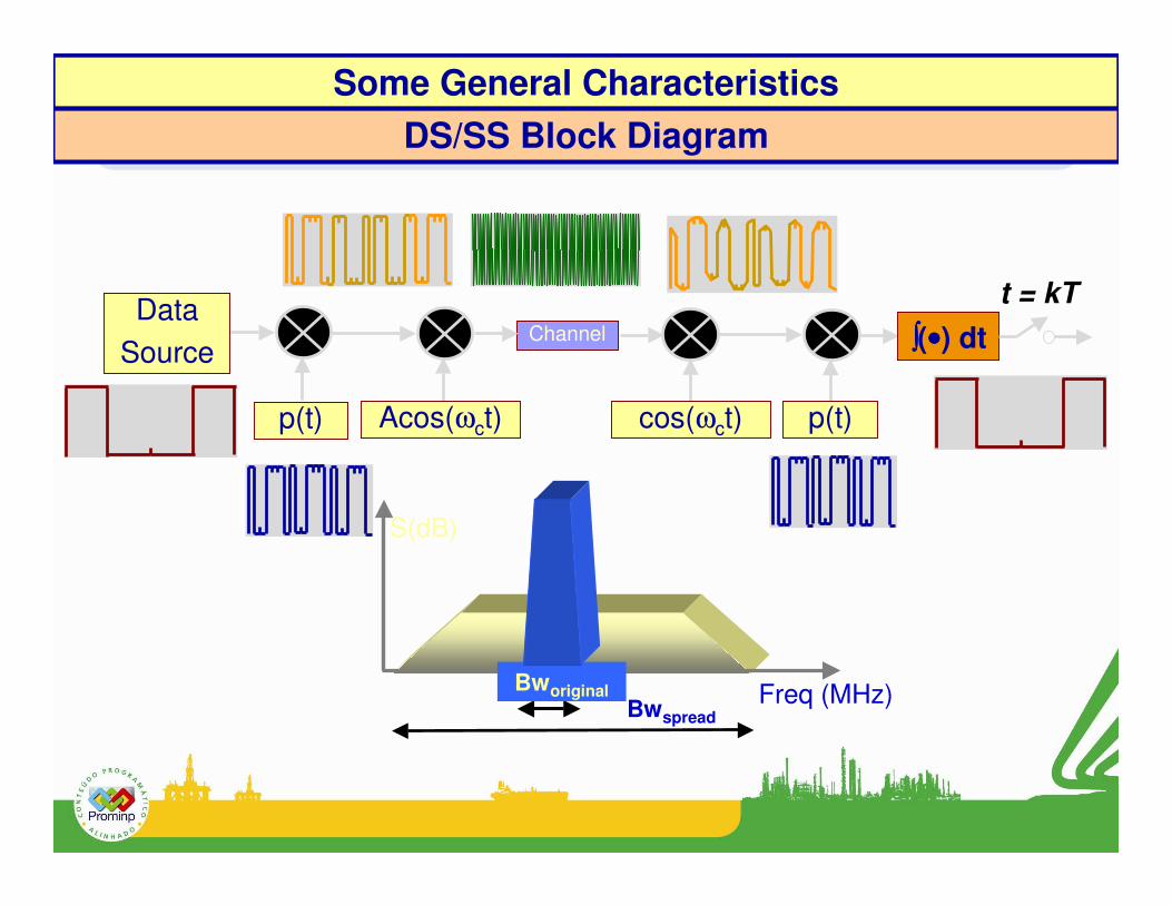
BwspreadFreq (MHz)
S(dB)
Bworiginal
Data Source
Channel
p(t) Acos(ωct) cos(ωct)
����(••••) dt
p(t)
t = kT
DS/SS Block DiagramSome General Characteristics

BPSK signal with power P, carrier frequency fo and a data rate Rb=1/Tb
Power Spectral Densities (PSD) of DS/SS Signals
]T)ff(sincT)ff(sinc[2
PT)f(G b0
2b0
2b ++−=

Previous BPSK signal spread by a code with a chip rate Rc=1/Tc
- Note that spreading maintains unchanged the total power P;
- The ratio G = Rc/Rb = Tb/Tc is known as processing gain and determines the interference rejection capability.

Previous signal and a centred tonal jammer with power J at receiver’s input

tcosJ2)t(j
)t(co)t(p)t(dP2)t(s
)t(j)t(s)t(r
0
0
ω=
ϕ+ω=
+=
tcos)t(pJ2)t('j
)t(co)t(dP2)t('s
)t('j)t('s)t(p)t(r)t('r
0
0
ω=
ϕ+ω=
+==
Therefore the de-spread effect is to return the desirable signal to its original form and to spread the interference (next slide).
Admitting a perfect code synchronism (i. e., p(t) has exactly recovered in the synchronism stage � p2(t) = 1) after de-spreading we have
The composed signal at detector’s input, r(t), can be written as

Previous signals now at detector’s output
This set of PSD figures shows the interference rejection capability and also the low probability of interception (LPI) for DS-SS signals.
bRcR
JP(SNR) D ×=