Embed Size (px)
Citation preview

Multiphysics Modeling of the Graphite Electrode Joint in Electric Arc Furnaces
for Scrap Steel Recycling
Nathan May
James Glickstein
Maren Waldner
1

Problem Statement
• The Electric Arc Furnace (EAF) uses graphite rods as electrodes to strike a powerful arc to melt scrap steel
• GrafTech International is a world leader in supplying graphite electrodes for the EAF process
2

Problem Statement
• The Electric Arc Furnace (EAF) is a massive industrial process, converting scrap steel into new raw material (millions of tons per year worldwide)
• Less greenhouse gas emissions versus Basic Oxygen Furnace steelmaking process (BOF, “Blast Furnace”) [1]
• BOF: 1.6 tonnes CO2/tonne steel
• EAF: 1.08 tonnes CO2/tonne steel
[1] US EPA, AVAILABLE AND EMERGING TECHNOLOGIES FOR REDUCING GREENHOUSE GAS EMISSIONS FROM THE IRON AND STEEL INDUSTRY, Sept 2012, https://www.epa.gov/sites/production/files/2015-12/documents/ironsteel.pdf
3

Problem Statement
• Previous finite element models have been very valuable to GrafTech’s electrode business
• Previous models were relatively simple and coarse; new software and hardware enable next-generation of FEM
• Develop a multiphysics model of the electrode joint, including:• Structural mechanics and contact physics
• Heat transfer
• Electric currents
• Validate model through comparison with real data
• Better understand process/performance relationships
• Reduce design cycle time
4

Problem Statement
Power CablesElectrode Clamp
Furnace LidGraphite Electrode
Electrode JointSteel Pile
5

Problem Statement
Power CablesElectrode Clamp
Furnace LidGraphite Electrode
Electrode JointArc
Steel Melt
6

Failure Mechanism: Stub Loss
7
Internal Threaded Pin
High Thermal Stresses
Stub Loss

Failure Mechanism: Oxidation
Graphite reacts with oxygen at high temp to form CO2 Characteristic
“oxidation profile” taper
Some materials/furnace conditions cause faster oxidation
8

Failure Mechanism: Column Break
Internal Threaded Pin
Bending force from scrap pile
Internal Threaded Pin
Bending force from scrap pile
9

Problem Statement
• Graphite Electrode consumption is a significant cost driver of EAF, in particular:• Stub loss: the tip of the electrode can crack and cause chunks of
electrode to fall into the melt• Oxidation: furnace temperature is well over 1000 degC, and
graphite oxidizes into CO2 rapidly at this temperature• Column breaks: “scrap cave-ins” or poor electrode addition exert
bending stress on column, leading to breaks high up and major process disruption
• Successive electrodes are connected at a “joint,” which becomes a critical point for reducing failure
• Because of the extreme environment, direct measurements are often difficult or impossible
• Graphite is a non-homogenous, anisotropic material
• Multiscale (>8 meters electrode and <10 microns defects) and multiphysics situation
10

Approach
• Make a model that considers all three failure mechanisms!
• Used COMSOL Multiphysics v5.3 (model developed in v5.0)• Structural Mechanics module• Heat Transfer module• Electric Current module• Moving Mesh module
• 2D Axisymmetric model:• Stationary pre-tensioning simulation• Transient multiphysics simulation of firing cycle
• 3D model:• Bending stress simulation• Transient multiphysics simulation of non-axisymmetric modes
11

Model Scheme
12
Flowing water w/phase change
Radiation from electric arc
Radiation and powerful convection from hot furnace
Contact physics for solid mechanics, heat transfer, and electric currents
Electric terminal

Model Validation
• Results were used on a comparative basis, in particular comparing the stress states of known failure location across different cases
• Used a variety of stress metrics, focusing on tresca and maximum principle stress criteria
• Focus on joint area as most common failure location
• Completed hundreds of simulations of different cases, grouped into about ten study areas
13

Stub Loss versus Firing Cycle
• EAF process has a characteristic firing cycle
• Involves heating and cooling segments
• Causes significant thermal stresses from temperature and material gradients
14

Stub Loss versus Firing Cycle
• EAF process has a characteristic firing cycle
• Involves heating and cooling segments
• Causes significant thermal stresses from temperature and material gradients
15

Stub Loss versus Firing Cycle
• EAF process has a characteristic firing cycle
• Involves heating and cooling segments
• Causes significant thermal stresses from temperature and material gradients
16

Stub Loss versus Firing Cycle
17
• EAF process has a characteristic firing cycle
• Involves heating and cooling segments
• Causes significant thermal stresses from temperature and material gradients
• Our analysis involves comparing these stresses at different times and places
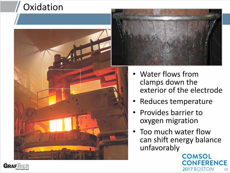
Oxidation
• Water flows from clamps down the exterior of the electrode
• Reduces temperature
• Provides barrier to oxygen migration
• Too much water flow can shift energy balance unfavorably
18

Oxidation
• Dependent on several factors:• Furnace type
• Furnace oxygen/inert gas usage
• Furnace power settings
• Water cooling
• Deep multiphysics coupling is required
• Simulate water as a phase-change domain (built-in to COMSOL), but with constant velocity field
19

Oxidation
20
No Water Flow With Reference Water Flow

Oxidation
21
With Reference Water Flow
• Use in-house testing to develop temp vs oxidation rate curves
• Integrate vs temperature and time
• Simulate total oxidation
• Test different materials’ oxidation rates, simulate consumption rate savings
• Predicted oxidation rates match reality quite well

Electrode Bending
22
Bending force from scrap pile

3D Cases
• 3D geometry is required for bending and other stress states
• Results make the model even more powerful, though require increasingly demanding hardware
• Model DoF/memory can exceed 2e7/350 Gb
• Results are very useful in understanding column breaks
23

Future Work
24
• Already a useful design and engineering tool for GrafTech
• More 3D simulations!
• Deeper sensitivity analysis vs furnace conditions and materials
• Crack propagation and failure at high temperature• Cohesive zone debonding
• Physical testing/comparison with DIC

Future Work
25
• Already a useful design and engineering tool for GrafTech
• More 3D simulations!
• Deeper sensitivity analysis vs furnace conditions and materials
• Crack propagation and failure at high temperature• Cohesive zone debonding
• Physical testing/comparison with DIC
¿Questions?Thank you for listening!
26
Thanks to Josh Thomas of AltaSim for help setting up
early model version!

Model Validation
27

Oxidation
• Oxidation is the baseline driver of graphite electrode consumption rates
• Around half of electrode baseline consumption is wasted as oxidation
• Improved technology has steadily reduced oxidation rates, but more can be achieved!
• Water cooling is one key reducer of oxidation
• Modeling can help us understand key operating parameters to control and limit oxidation
28