Embed Size (px)
Citation preview
buiLu uuti
* TAPE/SLIDE SYNC.
* INJECTOR/TRACER
* DRILL CONTROLLER
SIX PAGE
MULTIMEWRIDECHOOSING A METE1T-
A BASIC
DIGITAL SOUND SYNSYSTEM

ORIGINALEQUIPMENT
REPLACEMENT FOR
ONE
YEARUNCONDITIONALGUARANTEE
0
Nll
This is a partial list. Write for full tube listing catalogueTYPE EACH TYPE EACH TYPE EACH TYPE EACH
1B3GT 1.25 6BK4C 3.35 6HS8 1.90 10G F7A 2.501K3 1.35 6BL8 1.50 6HZ6 1.50 10G K6 1.801S2A ....... 1.35 6BM8 1.55 10G N8 1.851X2B 1.35 6JC6A 1.80 10JY8 1.85
6BN6 1.80 6J D6 1.85 10KR8 1.852AV2 1.25 61305 1.20 6JF6 3.902G K5 1.55 6B07A 1.50 11HM7 2.803A3A 1.95 6BU8A 1.90 6JS6C 3.45 11MS8 3.503AT2 1.90 6J T8 3.95
6BZ6 1.20 6JU6 3.50 12AT7 1.35
3AW2 1.75 6C4 1.25 6JU8A 1.90 12AU7A 1.003BW2 2.80 6CA7 3.40 6JW8 1.50 12AV6 1.003BZ6 1.00 6C B6A .95 6JZ8 1.90 12AX4GTB 1.50
3CB6 .90 6KA8 2.00 12AX7A 1.356CG3 2.25 61(06 3.95
3CU3A 2.90 6CG7 .95 6KE8 2.25 12BA6 1.05
3083 2.00 6CG8A 1.50 12BE6 1.05
3DC3 2.60 6CL8A 1.60 6KG6 3.95 12BY7A 1.20
3DF3 2.80 6CM7 1.30 6KT8 2.50 12C5 1.55
3DJ3 2.10 6KZ8 1.806CS6 1.35 6L6GC 2.60 1200613 2.25
3GK5 1.55 6CW4 6.25 6LB6 3.75 12DW4A 1.90
3HA5 1.85 6LD6 5.95 12GN7 2.00
3H05 1.90 6DJ8 2.10 6LE8 3.404AU6 1.55 6D06B 2.50 14GW8 2.00
6LF6 3.95 15008 1.604BZ6 1.35 6DT5 1.60 5LF8 1.854DT6A4EH74EJ7
1.551.551.55
6DT6A6DW4B6DX86EA8
1.201.851.601.50
6L.186LN86L066LT8
1.851.253.351.80
17AY3A1713E317BF11
1.601.552.50
4HA55A05
1.551.25
6EC46EH76EJ7
3.401.501.55
6LU86LX8
2.755.85 17DQ6B
17JN62.102.85
5CG85GH8A5GJ7
1.551.851.95
6EM76ES8
3.002.80
6SN7GTB
6U8A
1.90
1.25
17JZ817KV6A17KW6
1.853.955.60
5GS7 1.85 6EW6 1.35 6U10 2.505GX7 2.70 6FM7 2.00 6V6GT 1.95 18GV8 1.95
6W6GT 2.25 19CG3 2.505U85U4GB5U8
1.801.601.60
6GB56GE56GF7A
3.502.252.15
6X9
6Z10
2.95
3.25
21GYS21JZ6
3.153.20
6AF96AJ86A L36A L5
3.502.001.85.90
6GH8A6GJ76GK56GK66G M6
1.351.901.501.601.50
8AW8A8B88B108BM 11
1.851.902.903.75
23Z924L06
27GB5
2.653.50
3.35
6A05A 8CG7 .90 30AE3 1.706A08
.901.55 6GU7 1.35 8 DX8 2.55 30KD6 4.50
6AU6A 6GV8 1.95 8GJ7 2.25 31JS6C 3.956AV6
.956GW8 1.80 8JV8 1.85 33GY7A 3.25.956GX7 2.80 8LT8 1.85
6AW86AX36AX4GTB
1.601.701.60
6GY56GY66HA5
3.451.251.85
8U98X9
3.453.45
35W438HE738HK7
.903.503.50
6AY3B 1.60 9A08 3.25 401(06 3.806BA6 1.25 6HE5 2.70 9GV8 2.90 40KG6 3.956BA11 2.50 6H05 1.80 9JW8 1.60 42EC4 3.85613E6 1.20 6HS5 4.45 10DE7 1.85 5005A 1.35
11=1.11,
ap
U
CELEBRATING OUR19th YEAR
SERVICING THEELECTRONICS
INDUSTRY
FULL FUNCTIONCALCULATORfor only $1.99(including case)
With special orders of $100. or more
FULL FUNCTIONCALCULATOR* 8 Digit Display" Includes % Key* Add on and Discount
Features* 2 Input Registers* Constant Repeat
CalculationPLUS MANY MOREFEATURES
LIMIT 4 TO A CUSTOMER
en.
TERMS 8, CONDITIONS: ABBEY pays full shippingcharges anywhere in Canada on all prepaid orders over$25.00. C.O.D. orders, send 2 5 % deposits, balance
C.O.D. All orders shipped same day. Minimum order10 tubes.
306 Rexdale Boulevard, Rexdale, Ont. M9W 1R8 745-9555

KIT BONANZAELECTROLYTIC50 CAPACITORS
assorted 10uf to 150ufAXIAL
LEAD$395
50 FILMCAPACITORS
assorted values
NON
POLAR$195
100FOR THE
HOBBYIST
ASSORTED
RESISTORS
100 TRANSISTORSOCKETS
ASSORTED $195
100 ASSORTED
TRANSISTORS
$495
25 INTEGRATED
CIRCUITSASSORTED
$295
DOMINION RADIO & ELECTRONICS COMPANYTELEPHONE
924-1818nu: How,: (fl, BID") & ELEcTR0
( pplle.; 535 YONG E STREETTORONTO 5. ONTARIO
CORRECTIONFRON OUR SUf,INER CATALOGUE
(RMK)Record Maintenance Kit
$1895
4
AgA.:4 $1595
Manual Parastat(PA -MK -11A)
..4==a
Record Care Kit (RCK)
$650 111
Dust Bug (TDB)
$1 295
GRAPHIC EQUALISER. 25W +25WHI-FI AMP. LCUDNESS CONTROL.SIMPLE STEREO. BASS BOOSTER.STEREO FM TUNER. LINE AMP.GUITAR ATTACK COINITROiDUAI JECTS
giNO3---z; MINIMOIM11..-..x.--
- ....won AIMPrait. AP MM.DIGITAL DISPLAY,. IMPEDANCEMETER. 1TL SU-ERTESTER. DIGITALVOLTMETER. CAR ALARM. TACHOTIMING LIGHT., COLOUR ORGAN.RADAR INTRUDER ALARM. BIKESPEEDO. ELECTRONIC IONmON.AUTO-LUME. !FLUORESCENT LIGHTDIMMER. COMBINATION LOCK.DRILL SPEED CONTROLLER. LIGHT
NOW AVAILABLE IN CANADA!ETI TOP PROJECTS No.3
The thin in our popular series of reprints of the mostpopular projects in ETI. Includes projects for the audio-phile, motorist, for the home, test gear and many more.Full constructional details of each project are Given - 27in all, including a stereo tuner, 25W per channel amplifierand a graphic equalizer; put those together and you havea superb h -fi system.
Top Projects 3 costs only $2.50 - please order fromETI PUBLICATIONS
Electronics Today InternationalUnit Six
25 Overlea BoulevardToronto, Ontario M4H 1B1
ETI CANADA - JUNE 1977 3

TTL 7400NSN7400N .19 514741266SN7401N .19 80741280 .55SN7402N .19 514741320 .89SN7403N .19 SN74136N .48SN7404N .23 0874141N 1.09SN740511 .23 SN74142N 2.59SN7406N .49 SN74143N 2.60SN7407N .49 SN74144N 2.60SN7408N .22 SN74145N .8,SN7409N .22 SN74147N 2.55SN7410N .19 SN74148N 1.49SN7411N .29 SN74150N 1.50SN7412N .19 SN74151N .9bSN7413N .45 SN74152N 4.52SN7414N 1.25 SN74153N .89SN7416N .39 SN74154N 1.505074170 .19 0074155N .9HSN74200 .19 SN74156N .64SN7421N .29 0074157N .69SN7422N .19 SN7415914 2.255474234 .29 0074160N .9953174250 .29 SN74161N .99007426N .32 SN741620 .995474 2714 .30 SN7416314 .99SN7428N .30 54741640 1.10017430N .19 SN74165N 1.1,5574320 .29 SN74166N 1.3,SN74330 .30 SN741670 2.98SN7437N .36 SN74170N 2.60SN743831 .36 SN74172N 6.98SN74 40N .19 SN74173N 1.55SN744231 .59 SN74174N 1.15SN7443N 1.29 00741750 .995474445 1.30 SN74176N .8551474454 .99 SN74177N .85SN7446AN .99 SN74178N 1.25Si47447AN .89 SN74179N 1.2553474480 .95 SN74180N .99SN745031 .19 SN741810 2.755074510 .19 SN74182N .79NN7453N .19 0874184N 1.95SN7454N .19 SN74185A 1.85SN7460N .19 SN74186N 9.95SN74700 .34
0874190N 1.335574720 .27 54741910 1.33SN7473NSN7474N
.33
.33 SN741920514741938
1.101.10
0317475N .47 0574194N .9951474760 .36 SN741950 .59SN7480N .49 SN741960 .84SN7481AN 1.12 SN74197NSN7482N .79 00741980
.841.99
SN7483ANSN7484AN0074850SN74860
.90
.991.35.34
SN7419900874221058742460SN742470
1.991.101.351.29
5074895SN7490AN
3.10.47
SN742480SN742490
1.151.15
SN7491AN .b9 SN742518 .99SN7492ANSN7493ANSN7494N
.47.47
SN74259N0074265N
1.75.59
SD7495AN .39 SN74273N 1.74
0147496N SN74276N .89
5474975.842.85 SN74278N 1.99
S11741005 1.95SN74279N .59
50741040 60 SN742B3N .99
50741050 .60 SN74284N 4.00
0074107N .33 SN74285N 4.00
SN74109N .48 0074290N .69
55741100 .35 SN74293N .69
014741110 .49 SN7429814 1.49
SN741160 1.99 0074351N 1.79
SN74118N 1.50 0074365N .59
SN741190 2.50 0874366N .59
SN74120N 1.19 SN743678 .59
SN74121N .39 SN74368N .59
SN741220 .49 SN743900 1.24
574123N .69 SN74393N 1.24
:574125N .46 SN74490N 1.59
TTL LOW POWER SCHOTTKY..35
1.351.05
.0,41716N ZE9)
SN74LS161N 1.50SN74LS162N 1.50SN74LS163N 1.50sN74LS164N 1:50SN74LS165N 1.75SN74LS166N 1.75SN74LS168N 1.75SN74LS169N 1.75SN74LS170N 2.95SN74LS174N 1.10SN74LS175N 1.10SN74LS181N 3.25SN741S19014 1..59
SN74LS191N 1.59SN74LS192N 1.59SN74LS193N 1.59SN74LS194AN 1.25SN74LS195AN 1.25SN74L51960 1.35SN74LS197N 1.35
547475010 .2,
NN74L502N .25SN74LS03N .25SN74LSO4N .29
SN74LSO5N .29SN74LSO8N .25SN74LS095 .25
08741.010N .25SN74LSIIN .25
S074LS12N .25SN74LSI 3N .63SN74LS144 1.140074 LS15N0074 LS2ONSN74LS21NSN74L022NSN74LS26N5074702701113174L528N
SN74LS 30NSN741.0 32NSN74LS 13NS0741.5370SN74 LS 38NNN74LS4ONSN74LS42N
.25
.25
.25
.35
.30
.3>
.2;
.32
.13
.35
.35
.29
.80SN74LS47A 1.20087475480 .99
SN74LS49N .99SN74LSS1N .25
SN74LS.S4N .25
St474L555N .25
SN74LS63N 1.4911N741.573N .39SN74LS i4N .44
557475750 .64
5074LS76N .35O 11741,11178N . :9
5:174LN83A4 1.29
05 41,0855 1.35SN741.586N .49557470900 .74SN74LS91N .99SN74LS925 .74sN74LS93BN .748N74LS95AN .301'474319513N 1.35511741396N 1.49N N7416107N .4101.74 7010911 . 41
1111741.51120 .44SN74LS113N .44007470114N .445N74LS122N .69SN74LS123N .84SN74LS1245 1.50SN74LS125N .64
SN74LS126N .64
03174L5132N 1.1000741.01330 .29SN74LS136N .49
SN74LS138N 1.10SN74LS139N 1.10SN74LS145N 1.05SN74L515IN 1.05SN74LS153N 1.05
SN74 LS 221NSN74LS240NSN74 70241N03174LS242NSN74LS243NSN74LS244N5574152470SN74LS248NSN74LS249N05741.02515SN74LS253NSN74LS257NSN74LS2580SN743.025914SN74LS260N5574LS261N00743.02663101174LS2735SN74LS279NSN74LS2800SN74LS283NSN74LS290NSN74LS293N
1.291.951.951.901.901.951.151 151 151.251.251.251.251.59.29
2.25.49
1.80.641.951.251.051.05
SN74LS295AN 1.55SN74LS298N0874 LS3240SN74LS325N00741.0326NSN741.032700074LS352NSN74 LS 35331
SN74LS36555074 LS 3665SN74 LS 367N01174 LS 368N
SN74Ls375NSN74LS377N034743.0378N1074LS 386NSN74LS393NSN74 LS 395NNN74LS670N
1.55.992.752.802.701.201 35.64.64.64.64.64
1.801.35.49
2.251.553.25
LED'SUtronlxIllIL5IL12IL74RL2
.991.00
6070
.27
Texas Inst'mtsTIL111 .80TIL112 .80TIL113 1.20TIL114 1.10TIL116 1.05TIL117 1.20TIL119 .90TIL138 2.25TIL139 2.25TIL209A .17TIL211 .42TIL220 .18TIL221 .21TIL222 .36TI L302 3.95TIL303 3.95TI L 304 4.50TIL305 4.50TIL306 7.95TIL307 7.95TIL308 7.95TIL309 7.95TIL311 8.95TIL312 1.60TIL313 1.60TIL31 1.45TIL32 .85TIL66 .95TIL78 .55TIL81 1.15LS600 1.85
FairchildFCD802FCD806FCD810FCD820AFLV117 .18MV5054-1 .21
FND357 1.45FND500 1.50FND507 1.50FND807 2.95FNS700 .70
59.59.68.75
CD4000BECD4001BECD4002BE004006 BECD4007BECD4008BECD400980CD4010BECD4011BECD4012BECD4013BECD4014BECD4015BECD4016131CD4017BECD4018BECD4019BECD4020BECD4021BE0040220ECD4023BE0040240ECD4025BE004026800040270ECD4028BECD4029BE70403000C040331300040340E0040350E0540408ECD4041BECD4042BE0040430E0040440E0040468E1940498E9-1050BE1)HBE
0140
C / MOS LINEARS.15 0040730E .29 LM301AH .45.19 CD4075BE .29 LM301AN-8 (mini dip) .39.19 CD4076BE 1.50 LM304H .95
1.19 CD4077BE .29 LM305H .95.19 0040780E .29 LM307H.99.49
05408181CD4082BE
.29
.29 LM307N-8 (mini dip).40.39
.49 CD4080BE .69 LM308H .99
.19 CD4083BE .69 LM309H .99
.19 0043016E .65 LM309K 1.79
.47 CD4502BE 1.25 LM311H .99
.79 0045078E .65 LM318H 1.50
.89
.4720451080CD4511BE
1.351.45 LM323K 6.95
.89 Cl4512BE LM324N .99
.89 0045148E 2.50 LM339N .99
.49 0045158E 2.50 LM555N-8 .491.15 CD4516BE .95 LM556N-14 .89.79 0045170E 4.00 LM709CN-14 .29.99 CD4518BE 1.0; LM711CH .60.19.89
CD451913E00452030.
.69
1.19LM723CH .55
.19 Cl4522BE 1.30 LM723CN-14 .49
1.75 0045260E 1. 3, LM733CN-14 1.10.44 0545273E 1.99 LM739N-14 1.25.85 CD4528BE 1.19 LM740CH 9.95.99 CD4531BE 1.20 LM741CH .45.49
1.75CD4539BECD4543BE
.991.9'
LM741CN-8 (mini dip) .34
2.50 2045556ELM741CN-14 .35
1.15 CD4556BE.69.69 LM747CN-14 .55
1.15 0045818E 3.25 LM748CN-8 (mini dip) .38.84 CD458280 1.25 LM748CH .39.84 CD4585BE 1.49 LM776CH 3.75.79 40014PC .79 LM1437N-14 .49.79 40085Pc 1.10 LM1458H
1.55.47
.47
40097PC40098PC40160PC
.89
.891.35
LM1458N-8 (mini dip)LM1488D
.79
.591.50
.89 40161PC 1.35 LM1489D 1.50
.89 40162PC 1.35 LM3046N-14 .58
.89 40163PC 1.35 LM3302N-14 .79
.35 40174PC 1.25 LM4136N-14 1 45
.74 40175PC 1.25
.29 40192PC 1.35
.29 40193PC 1.3539 40194PC 1.29
40195PC
We offer the largest variety of currentproduction Texas Instruments andFairchild Semiconductor only 74LSdevices from stock. Even through thecompetition for current productionmajor manufactured 74LS devices islimited, we are dedicated to provide thebest prices possible. As our costsdecrease. we pass the savings on to you,our customer.
Plastic PowerTransistors
TIP29A 39TIP30C 54TIP31A 45TIP32ATIP33CTIP41ATIP42ATIP47TIP112TIP116TIP117TIP121TIP122TIP125TIP127TI P2955TIP3055
48.8365746070
.7090
1.051.201.051 35
8979
LINEAR VOLTAGE REGULATORSTL497CN 2.50 Switching Voltage Regulator 500 mA
Adjustable Output78H05KC 7.95 5 Amp 5 Volt Positive Regulator T037800 Series 1.79 Positive Voltage Regulator 1 AmpTO -3 /LM340K 5. 6, 8, 12, 15, 18, 24 Volts7800 Series 1.35 Positive Voltage Regulators (Plastic) 1 AmpTO-220/LM3407 5, 6, 8, 72, 15, 18, 24 Volts78M00 Series 1.59 Positive Voltage Regulator 05 AmpTO -5 /LM340H 5, 6. 8. 12, 15, 18, 24 Volts78L00 AWC 49 Positive Voltage Regulator 100 MASeries TO -92 26, 5, 6.2, 8.2, 12. 15 Volts7900 Series 2.50 Negative Voltage Regulator 1 ampTO -3 /LM320K 5, 6. 8, 12, 15. 18, 24 Volts7900 Series TO- 1.59 Negative Voltage Regulator 1 amp220/LM320T 5. 6, 8, 12. 15, 18 24 Volts79M00 Series 1.59 Negative Voltage Regulator ampTO-5/LM320H 5. 6, 8, 12. 15. 20, 24 Volts78MGT2C 1.35 Dual In Line Adjustable 4 Terminal Positive
Voltage Regulator79MGT2C 1.35 Dual In Line Adjustable 4 Terminal Negative
Voltage Regulator78GU1 TO -220 1.60 1 Amp Adjustable Positive Voltage Regulator79GU1 TO -220 1.50 1 Amp Adjustable Negative Voltage Regulator78GKC TO -3 ZOO 1 Amp Adjustable Positive Voltage Regulator79GKC TO -3 2.50 1 Amp Adjustable Negative Voltage Regulator
MOS AND BI -POLAR MEMORIESC1702A (1 Microsecond)
256 x 8 EPROM 11.65C1702A (1.5 Microsecond)
256 x 8 EPROMC2708 1K x 8 EPROM (450 NS)8080A 8 Bit MOS Cpu (2 Microseconds)2102-1P 1K Static Ram 1024 x 1 (450 NS)3342PC Quad 64 Bit Static Shift Register3347PC Quad 80 Bit Static Shift Register3341APC 4 x 64 MOS Fifo 1 Mhz Shift
Register 5.85TMS0117NC Decimal Arithmetic Processor 13.00LCM1001 Microprocessor Learning Module 180.00TMS4024NC 64 x 9 Fifo 095TMS4050NL 4K Dynamic Ram Plastic 300NS 9.25
118 Pin)
TMS4060NL 4K Dynamic Ram Plastic 30ONS 9.25(22 Pin)
AV5-1013P 8 Bit UartSerni4804A 4K Static Ram 1024 x 4 (450 NS)
Single 5V Supply93415PC 1K Ram 4ONS Open Collector93425PC 1K Ram 40 NS Tri-StateAM2901DC 4 Bit Bi-Polar Microprocessor
SliceAM29O2PC Carry Look Ahead CircuitAM2905PC Quad 2 Input Bus TransceiverAM2907PC Quad Bus Transceiver with Tri-
State Receiver and ParityAM2909PC 4 Bit Cascadable Microprogram
SequencerAM2918PC Quad Deregister with Standard
and Tri-State OutputsF8 Kit 8 Bit Microprocessor Evaluation
Kit With Software 225.00
7.7535.0019.45
3.255.855.85
6.95
19.4514.3014.30
40 954.15
10.55
9.10
9.30
5.65
TEXAS INSTRUMENTS DATA BOOKSSTK. NO.LCB1011
LCB1891
LCC4041LCC4112LCC4131LCC4151LCC4200LCC4230LCC4241
DESCRIPTIONUnderstanding Solid State
ElectronicsSoftware Design for
MicroprocessorsPower Data BookTTL Data Book
Transistor and Diode Data BookLinear and Interface I.C. Data BookSemiconductor Memories Data Book
Optoelectronics Data BookLinear Control Circuits Data Book
PRICE3.65
15.25
4756.456.254.753.453.853.75
FAIRCHILD DATA BOOKSPower Data Book 3.90Bi-Polar Memory Data Book 125Linear Integrated Circuit Data Book 3.85Low Power Schottky andMacrologic TTL 2.30Interface Data Book 1 30
Raytheon Linear Integrated Circuit Data Book 1 95Solid State Scientific CMOS'S' Series Data Book 3.25Unit rode Semiconductor Data Book 6.45
"ONLY MAJOR MANUFACTURERS SUPPLIED""This is a partial listing. Our complete catalogue listsmany more device types & series which are available""Our quality cannot be surpassed"."How can you beat the combination the finest quality:current production; latest date code devices from themajor manufacturers as Texas Instruments & FairchildSemiconductor - At the lowest prices - Surely anunbeatable combination. Get the most value for yourDollar".Active Electronic provides the three essentials inSemiconductor Distribution1. QUALITY2. INVENTORY3. PRICEWe now offer the lowest mix pricing for majormanufacturers devices only: with the largest variety ofdevices available from stock, from one source.We offer Rolls Royce quality at Volkswagon pricing.
Active Electronic Sales Corp."New catalogue available on request" Minimum Order51000 and add $1.00 to cover postage and handling.Prices are in U.S. Funds, duty included. All Federal andProvincial Taxes extra. II you wish to pay in CanadianFunds. please add 5°o.
5647 Ferrier St. Montreal, Que. H4P 2K5 Phone: (514) 735-6429
Toronto, Ontario44 Fasken Drive, Unit 25, Rexdale, Ontario
Phone: (416) 677-4287
Store Hours, Monday -Friday 9:00-5:00 Saturday 9:00- 1:00
4 ETI CANADA - JUNE 1977

Features
DIGITAL SOUND SYNTHESIS 16From monophonic to polyphonic
A GENERATION AWAY 25Evolution or revolution
MULTIMETER GUIDE 30Make sure you get what you want
LIQUID CRYSTAL DISPLAYS 40What goes on behind the screen
INTRODUCTION TO COMPUTERS 44What's involved and how its evolved
Projects
G.S.R. MONITORLearn to relax with this unit
12
TAPE/SLIDE SYNC 36Update your slide shows
SHORT CIRCUITSINJECTOR TRACER 54METRONOME 56DRILL CONTROLLER 57
Information
TOP PROJECTS NO. 3 3
NEWS DIGEST 6
SUBSCRIPTIONS 15CIRCUITS BOOK NO. 1 24JULY ISSUE REVIEW 29READER SERVICES & INFORMATION 48PUBLICATIONS FROM E T I 50DATA SHEET 51
TECH TIPS 59
Second Class Mail registration number3955. Return postage guaranteed. PostOffice returns to Unit 6, 25 OverleaBoulevard, Toronto, Ontario, M4H 1131.
Vo1.lNo.5 June1911
EDITORIAL AND ADVERTISINGOFFICES:Unit 6, 25 Overlea Boulevard,Toronto, Ontario, M4H 1B1Telephone (416) 423-3262EditorMIKE KENWARDAssistant EditorGRAHAM WIDEMANCirculation Dept.SENGA HARRISON
Marketing Manager and AdvertisingPETER PRIEST
Editorial DirectorTOM GRAHAMPublished by:Electronics Today International(Canada) Ltd.Printed by:Heritage Press, Mississauga, OntarioNews Stand Distribution:Gordon & Gotch, TorontoSubscription Rates:$12.00 per year, $20.00 for two yearsSend to Subscription Dept, ETIMagazine, Unit 6, 25 Overlea Blvd.,Toronto, Ontario, M4H 1B1.
International EditionsBritain:Electronics Today International25-27 Oxford St., London W1R 1RFEditor: Halvor MoorsheadAustralia:Electronics Today International,Ryrie House, 15 Boundary St.,Rushcutters Bay, Sydney, AustraliaEditor: Collyn RiversHolland:Electronica Top Internationaal,Postbus 260, Emmen, HollandEditor: Denis LoosFrance:Electroniques Pour Vous International42 rue Jacob, ParisEditor: Denis Jacob
Copyright: All material is subject toworld-wide Copyright protection.All reasonable care is taken to ensurethe accuracy of the information.
Ell CANADA - JUNE 1977 5

NEWS DIGEST
PROGRAMMABLE TRAFFICIt may not be long before yourfavorite radio traffic reporter will beable to accurately forecast, inminutes, how long it will take youto reach your destination - andeven suggest alternate routes basedupon shorter travel times.
Bob Benedetti, an investigativereporter for CFCF television inMontreal, Quebec, and formerhelicopter -based traffic reporter,has developed a method ofaccurately predicting trafficmovement by using a tiny hand-held programmable calculator.
Throughout 1975, Benedetti wasproviding to his listeners extremelyaccurate forecasts of times todifferent destinations. Thisaccuracy was hardly based uponintuition. Cradled on his lap in thehelicopter was a Hewlett-Packardprogrammable pocket calculator. Inhis pocket were five magneticcards, each the size of a stick ofchewing gum, upon whichBenedetti had recorded a series oftraffic flow estimation problems.
Hovering over a section ofhighway, Benedetti would clock thepassage of cars through apredetermined length of road.Programming the calculator byinserting a magnetic cardcorresponding to the task,Benedetti would then key in the testdistance, time measurement anddistance to the destination. Thecalculator would provide the traveltime in minutes.
Says Benedetti, "In my initialtests, I tried using a simple four -function calculator, but theconstant repetition of the sameproblem was just too difficult whiletrying to keep my eye on the road
below me. The programmable HPcalculator allowed me to developprograms in my spare time andsimply enter data into the machinewhen I needed it.
Since leaving his position as atraffic reporter, Benedetti hasfurther improved his trafficmonitoring programs as well asused the calculator for such diverseneeds as real estate and incometax. He is presently offering thetraffic monitoring programs tointerested reporters.
MICRO -68 KITAfter two years production of theMicro -68 computer San Diego -Electronic Product Associates hasannounced kit form availability.Cost is U.S. $385.00 complete withpower supply and cabinet. TheMicro -68 uses the industry standard6800 microprocessor which is nowmanufactured by Motorola, AMI,Fairchild, Hitachi, and ThomsonCSF.
The kit comes complete with a 16key hexidecimal keyboard and sixdigit hex display. Sockets areprovided for 768 words of RAM(128 words supplied with kit).
The following commands are partof MON-1, inspect and change,load users program, run usersprogram, insert break points, savestack, vector interrups, sixteen bitsof I/O are provided to the sideconnector, and the main bus isavailable at the front connector.Full bus buffering provisions areprovided on the board. A piggy-back teletype/CRT/Audio CassetteAdapter is available.
The Micro -68a is fully compatiblewith the Micro -68b for laterupgrading into a larger system.
For additional details contact:Electronic Product Associates, Inc.,.1157 Vega Street, San Diego, CA92110.
NEW TECHNOLOGY USEDTwo new Motorola products haverecently been announced, they area series of r.f. power transistors anda precision voltage reference briefdetails of each are given below.
The new r.f. power transistorsextends r.f. power outputcapabilities to 80 Watts in the 100to 500 megahertz range.
The devices are designed forbroadband operation as Class A,AB, B and C transmitter amplifiersin u.h.f. communications equipmentoperating from a 12-28 Volt powersupply.
The stable 2.5 Volt referencesource, type number MC1403/1503has been designed for criticalinstrumentation and D -A converterapplications, the low-cost mono-lithic circuit features a maximumoutput voltage variation of only 1°k(+25mV) and a typical temperaturecoefficient of 10 ppm/°C.
Laser trimming of resistivenetworks as a routine processduring normal manufactureprovides a high yield to a very tighttolerance specification.
This chip also represents the firstutilization of a p -channel J-FET in a
linear integrated circuit at Motorola(a relatively new productiontechnology). Ion implantation is thetechnology responsible for thiscapability.
Looking more like a hybridintegrated circuit than a discretetransistor, Motorola's newest line ofUHF power amplifier devicesfeatures double tuned inputmatching networks to multipletransistor array in order to achievebroadband operation - 100 to 500MHz - with power output as highas 80 Watts.
6 ETI CANADA - JUNE 1977

BIG BRIGHT CHARACTERSA high brightness character displaytube which operates on a newprinciple has been developed bythe English Electric Valve Co., Ltd.,The display can be manufactured insizes up to about 25 inchesdiagonal and can display specialcharacters.
The 7 -segment tube operates in amanner similar to a cathode raytube. A front faceplate carries ahigh luminance, high -efficiencyphosphor energised by a floodbeam of electrons from thecathode. Placed between thecathode and the faceplate is aseven -segment mask with a leadfrom each of the segments broughtout separately so they can beswitched.
It is extremely easy to switchfrom one character to another atelectronic speeds, only low leveldriving logic is required.
The displays come in colours ofGreen, Red, Blue, White andYellow.
JUST ASK ME!LED or liquid crystal? The
question may never occur in thefuture, not because one willsupercede the other but becauseyour watch may be able to tell youthe time - literally. No, its notscience fiction, a patent hasrecently been granted toIntersonics of New York for abattery operated watch thatcombines a numerical display witha speaker and bubble memory thatenables the watch to tell you thetime in any language the buyerrequires.
SIGNING INField troubleshooting to thecomponent level of micro-processor -based products designedwith Hewlett-Packard's newsignature analysis service techniqueis greatly simplified with this newservice instrument.
Called the Model 5004ASignature Analyzer, the newinstrument is designed specificallyfor use in signature analysisservicing. It locates faulty bitstreams in microprocessor -basedcircuits with an accuracy of
99.998%. Because of complextiming relationships within logiccircuitry, conventional servicetechniques using oscilloscopes andvoltmeters are not adequate toeasily locate faults to thecomponent level.
The 5004A checks operation ofmicroprocessor -based productswhere data streams are long andcomplex. It recognizes and displaysa unique hexadecimal number(signature) associated with eachdata node in the circuit. Signaturesdisplayed on the 5004A arecompared with correct signaturesprinted on the schematic of thecircuit under test. If a wrongsignature appears, the technician isguided, with the help of servicenotes, through the circuit to thefaulty component.
Products must be designed withsignature analysis service in mind.However the cost of designingsignature analysis into a complexmicroprocessor -based product can,in most cases, be more than offsetby savings in production costsbecause of fewer printed circuitboards and fewer interconnectionsrequired.
Information on this product isavailable from Inquiries Manager,Hewlett Packard (Canada) Ltd.,6877 Goreway Drive, Mississauga,Ontario.
ETI CANADA - JUNE 1977 7

NEWS DIGEST
Naked Mini -4 Family claimed to put an end to compromise in minicomputer selectionby OEM and volume users through design modularity, upward and downwardcompatibility, exclusive input/output flexibility, and a very broad range of memory
The computers are LSI 4/30, LSI 4/10, and LSI 4/90 (left to right).Packaged versions come in operator's (left) or programmer's console.
A0534XIN
YIN
VOLIT
ANALOG DEVICES AD534 MONOLITHIC, LASER WAFERTRIIVIMID,OUL TIPLIER
MINI -FAMILYA new minicomputer family that isclaimed to shatter previouslyexisting price/performance barriers,while broadening the range andlevel of products available to OEMand volume user markets from asingle source has been announcedby Computer Automation, Inc.
The new line of NAKED MINI -4computers includes threeprocessors with a kinship based ontotal compatibility of hardware andinterchangeable software.
Highlighting the new family is theLSI 4/10, a full 16 -bit minicomputeron a board priced as U.S. $645. TheLSI 4/10 incorporates two customn -channel MOS chips, 4k words ofRAM memory, and 4 input/outputchannels, all packaged on a halfsize (71/2 x 15 inches) circuit card.On -board battery backup is anavailable option.
LASER TRIMA new laser -wafer -trimmedmonolithic multiplier (AD534) isavailable in five versions includingthe AD534L which features amaximum multiplication error of+0.25 per cent at 25°C, claimed tobe the lowest of any IC. The newAD534 is the latest in a series ofmonolithic multipliers from AnalogDevices; it requires no externalcomponents, and features feed -through of no more than 0.12% onthe X input and no more than 0.10%on the Y input. Maximum offsetvoltage is 10mV; Nonlinearity is0.1% maximum, and noise is only1mV r.m.s. over a wide (10Hz to5MHz) bandwidth.
"Since we use a unique,automatic laser -trimming techniquethat allows us to trim resistors atthe wafer level, we can offer ourcustomers the performance of amodule with the package and priceadvantages of an IC."
Devices are available throughTracan Electronics Corp., 558Champagne Drive, Downsview,Ontario M3J 2T9.
RADIO CONTROL
A communication has recentlybeen received from the Departmentof Communications regardingfrequencies and power allowed onmodel control bands. Havingsubbed out the sub -paragraphreferences the basic information isthat it is proposed to amend theRadio Act, to increase from 4 to 8the number of frequencies in the
72MHz band used for radio controlThe proposed bands being 72.08,72.24, 72.40, 72.72, 72.76, 72.80,72.84 and 72.96 MHz. And toprescribe a maximum power limit ofone watt for "radio apparatus"operating on all v.h.f. model controlfrequencies. - this does notinstigate any change in allowablepower. There will be no change tothe 27 MHz or 53MHz bands.
The Department invites manu-
facturers, users, associations,groups and interested persons tomake any submissions they wishconcerning these proposedregulations. Submissions should beaddressed to the Director,Operations Branch, Telecommuni-cation Regulatory Service, 300Slater Street, Ottawa, Ontario, KM008 and should be post -marked notlater than 60 days after the date ofthis notice (dated May 6, 1977).
8 ETI CANADA - JUNE 1977

NEW LITERATURENearly swamped by new material fromH.P. we have had to go through it forthe most interesting and useful pieces- no doubt they will tell you abouteverything they have should you beinterested. All the releases were datedMay 5, here are the ones we selected.- all are free from Inquiries Manager,Hewlett Packard (Canada) Ltd., 6877Goreway Drive, Mississauga, Ontario.
MODELING AND SIMULATIONFOR DIGITAL TESTINGModeling and simulation for digitaltesting is the subject of applicationnote (AN 210-1); intended to help thedigital circuit designer and testengineer understand the technology ofmodeling and simulation, this tutorialtext explains software simulationtechniques and the benefits that can bederived.
Sections included in this 48 -pagebooklet discuss fundamentals of digitaltesting, logic model elements, logiccircuit simulation.and modeling andsimulating faults.
Although the text of AN 210-1 istechnical and includes many specificcircuit examples, it is easy tounderstand by anyone with aknowledge of digital circuits.
9825A DESKTOP COMPUTINGSYSTEM
A technical data sheet describing theHewlett-Packard 9825 desktopcomputer, designed for stand-alonecomputing or industrial and scientificsystem control applications. The 12 -page data sheet (#5953-0222) alsodescribes available software, read-onlymemories, interface cards andperipherals for the 9825.
DIGITALLY CONTROLLED
POWER SOURCES
Describes the H.P. family of digitallycontrolled power sources whichincludes three voltage sources and onecurrent source - all offering flexibleinterfacing.
Twelve pages, illustrated with photosand diagrams, the brochure givesinformation on the power sourcesincluding performance and generalspecifications, ratings, prices, optionsand accessories. Many digital interfacerequirements can be satisfied by astandard, HP-IB or a special interfaceoption through the use of plug-in cardsthat determine the data format (eitherbinary or 8-4-2-I BCD), the logic senseand the logic levels required toprogram the instruments. Many other
system -oriented features have beenincorporated so that these completedigital -to -analog subsystems can beintegrated with ease into automatictesting and control systems.
The brochure is entitled "DigitallyControlled Power Sources Models6129C -6131C, 6140A" (Pub. #5952-3996D).
INTERFACE BUSAn explanation of instrument,computer interfacing, and thedevelopment and use of the Hewlett-Packard Interface Bus (HP'simplementation of IEEE Standard488).
The brochure covers the evolution ofan interface standard, HP-IBapplications, HP-IB controllers,instruments and accessories, standardinterface systems, and a bibliographyof pertinent literature. (Pub. #5952-0050).
Other literature comes from a varietyof sources on various subjects, twoselections from Motorola are:
HEP SEMICONDUCTOR GUIDEHEP semiconductors are offered asreplacements for over 60,000 differentdiscrete devices and ICs. Intended for,but not limited to, the hobbyist,experimenter and the professionalservice technician/dealer, the HEPproducts are specified to meet orexceed the important mechanical andelectrical characteristics of the replaceddevice. In many cases, one HEP devicewill be recommended as thereplacement for a large number ofcomponents. Because this one -to -manyratio, the HEP device specificationswill often exceed some of thespecifications of a number of thereplaced devices.
Because Motorola is not responsiblefor the design of the circuits in whichHEP products are installed, andbecause the HEP device parametersmay exceed the original, MotorolaSemiconductor Products, Inc., doesnot guarantee that the HEP devicewill perform exactly as the originaldevice. However, the availability of thisvast array of potential replacementdevices, through a large, national,network of retail outlets, (over 1500)can offer a considerable savings of timeand money, or both, to the hobbyistand professional technician, alike.
The latest edition of the MotorolaHEP Semiconductor Cross ReferenceGuide and Catalog is now available.
This 184 page book describes discretesilicon and germanium powertransistors, thyristors, small -signalFETs and bipolar transistors, C.B. RFpower transistors, zeners, rectifiers andopto-electronic devices. Digital ICs, inRTL, HTL, DTL, TTL and CMOStechnologies, are also included as wellas linear bipolar radio/ television ICs,voltage regulators, op -amps, etc.
One hundred and ninety-eight newproducts have been added to theCatalog; 104 are newly offered TTLfunctions.
The Catalog also describes theEducator II Microcomputer and PowerSupply Kits. The Microcomputer isbased on the popular M6800technology.
The unit price of this new MotorolaHEP Semiconductor Cross ReferenceGuide and Catalog is $2.00;availability: from HEP/ MROOperations Headquarters and HEPdistributors. For further information,please contact: Motorola HEP/ MRONational Sales Manager, 705 West22nd Street, Tempe. Arizona, 85282(602) 244-3208.
On a similar basis for the electronicsindustry is the new Motorola MasterSelection Guide and Catalog. Availablefrom any OEM sales office or fromany OEM sales or franchised Motoroladistributor.
The MSG and C contains listings ofall Motorola standard semiconductorproducts, ranging from the mostcomplex microprocessors tocommodity diodes and transistors. Allproducts are arranged, in alpha-numeric tables for easy identification,and in applications categories, togetherwith technical specifications, for easycomparison and selection. It representsthe basic document which is updated,every other month with new -productdescriptions in the SemiconductorData Update.
9ETI CANADA - JUNE 1977

NEWS DIGESTA 1977 catalog has recently beenannounced by Continental SpecialitiesCorporation, manufacturers ofbreadboarding and test equipment forthe professional and hobbyist.
The I6 -page catalog features thecomplete line of QT Stockets, proto-clips, proto-boards, logic probes, logicmonitors and design mates andintroduces the new experimentorsockets.
Catalogs are available from:Continental Specialities Corporation,44 Kendall Street. P.O. Box 1942, NewHaven, CT 06509.
Analog Dialogue (Volume 11, No. 1,1977), available free from AnalogDevices, P.O. Box 280, Norwood,Mass. 02062, features a variety of newproduct articles and applications noteson electronic devices for measurementand control instrumentation andmicrocomputer -based control systems.
Included in the 20 -page publicationare new product articles onmicrocomputer interfaces, ICmultipliers, V/ F converters, true-RMSdigital panel meters, and both 10 -bitand 18 -bit D/ A converters.
WAComas Ltd
111 ,1114.3 7100
11:112111EOM=El r
COMPONENTSA copy of an RS Components
(British company) catalog with a NorthAmerican price list has come our wayfrom WA Components Ltd., 65Granby St., Toronto, Ontario, M5 B1 H8.
WA state that they have extensivecontacts both in Europe and the U.K.and are always pleased to quote foritems not listed.
It may be of interest that thecompany was originally formed as anoffshoot of a recording company, whenit was found nigh on impossible to
obtain spares for European equipmentthey started to import same. It wasfound that others made use of theservice and continued from there.
A charge of $1 is made for thecatalogue, which contains 128 pagespacked full of general purpose items,the charge is refundable against aninitial order.
CB ACCESSORIES CATALOG
A new 24 page CB Accessories Cataloghas been published by GC Electronics;all accessories are approved for 23 or40 channel radios.
Featured in the catalog aremicrophones, connectors, audio systemaccessories, antennas and exactreplacement parts, auto alarms,mounts, cables, interferencesuppressors, maintenance items andperformance indicators.
GC Electronics, 400 South Wyman,Rockford, Illinois 61101, manufacturesa complete line of CB productsincluding Globe transceivers and CBaccessories.
31/2 DIGIT DMM
It has been pointed out that theB&K Dynascan Model 2800 31/2 digitportable DM M , mentioned last monthis available in Canada throughdistributors at a recommended retailprice of $142.15 net.
The Canadian representatives forB&K are Atlas Electronics Ltd., 50Wingold Ave., Toronto, Ontario, MG51 P7. Their branch office is at 3333Cavendish Blvd., Montreal, Quebec,M4 B 2M5.
CLASSIFIED
Classified AdvertisingBox Numbers
Classified advertisers wishing to usea Box Number in their advertise-ments MUST supply their perma-nent address and telephone number.Advertising will not be accepted ifthis information is not supplied.Advance payment must accompanyall orders. Send cheque or moneyorder, not cash, to:Advertising ServicesETI Magazine - Unit 625 Overlea Blvd., Toronto, Ontario
J & J ELECTRONICS LTD.,P.O. Box 1437 E,Winnipeg, Manitoba R3C 2Z4Semiconductor SpecialistsDo you get our bargain flyers? Send$1.00 to receive the current literatureand specials and to be placed on themailing list for the future publications.
FREE! New 64 page electronicsparts and surplus catalog jam
packed with exciting items andhard to find bargains for
hobbyist, industry and schools.Thousands of super buys in;
Electronic parts, motors, hardware,microphones, semis, fans, assembliestimers, knobs, connectors,CB accessories, speakers, trans-formers, telephones, leds, ICs, opticswire alarm parts, meters, amplifiers,kits, photocells, TV parts, audioaccessories, computer parts, powersupplies, bulbs, transmitters, fuses,switches, tape, heaters, crystals, etc.etc. Over 100 top name stereo brandsdiscounted. Amazing values foreveryone. We are big buyers offactory clearouts, distress merchan-dise and government surplus.Largest inventory of surplus inCanada
ETCO ELECTRONICS, Dept.ETI, 183G Humus Blvd., PointeClaire, Quebec. H9R 1E9
TOP QUALITY°ETI CIRCUIT BOARDS
BOARD PROJECT PRICE EA.
122 LOGIC TESTER 6.5044450 5W STEREO AMPLIFIER . 6.00445 GEN. PURPOSE PREAMP 2.00447 AUDIO PHASER 5.50448 DISCO MIXER MAIN BD. 6.50448A HEADPHONE AMPLIFIER 2.00449 BALANCED MIC PREAMP 2.50449A VU CIRCUIT 3.50480 50/100W AMPLIFIER 6.00480PS PWR SUPPLY FOR 480 5.005700 REACTION TESTER 5.85
ASTERISKED ITEMS IN STOCK. ALLOW 2 TO5 WEEKS FOR DELIVERY ON OTHERS. MOSTPARTS FOR ABOVE PROJECTS ARE IN STOCK.
- STOPWATCH HITOne of the marvels of the LSI age. Kit includesIC, crystal, small ports to convert a low costcalculator info a 6 digit, battery operated timerstopwatch. Display can be held for timing lapsor multiple finish events while clock continuescounting elapsed time. Operates in Split/Taylormodes. Counts to 59 min 59 sec 99 hundredths.
STOPWATCH KIT, less calc.& bty. $38.95
Boards postpaid in Canada. IC's, etc.add 50c to total for P&P. Ont. residentsadd 7% provincial sales tax. No COD'sWRITE FOR LATEST CATALOGUE
cAnELECTROnicsMOS BOH 1690,
C PETERBOROUGH,ant H91754
10 ETI CANADA - JUNE 1977

GAMASONIC CANADA LTD./LTEEOUR PRODUCTS
=MM.'
gIELF[123
ELECTRONIC PARTS
HiFI ACCESSORIES
HEADPHONES
MICROPHONES
8 TRACK TAPES
CABLES
em;Fandt
TELEVISION ANTENNAS
Goodmans RAW SPEAKERS
65
SANYO AUTOMOTIVE SOUND
EQUIPMENT
TRANSCEIVERS
CB MOBILES -BASE
VTR -CCTV EQUIPMENT
CAMERAS -MONITORS
VIDEO RECORDERS
NEC VTR EQUIPMENT
SA NYC) VTR CAMERAS -MONITORS
VIDEO RECORDERS
Gamasonlc Canada Ltd./Ltee,5780 Royalmount Avenue,Montreal, Quebec H4P 1K5Tel: (514) 735-2721
HALIFAX TORONTO
WINNIPEG EDMONTON VANCOUVER
ETI CANADA - JUNE 1977 11

G SRLearn to reduce tension levels with ET I 's galvanic skin response meter. Designby Barry Wilkinson - editorial by Jan Vernon.
MONITORTHE BEST WAY TO START EXPER-imenting with biofeedback is to use agalvanic skin response monitor, a devicewhich measures changes in skin resist-ance. In September 1976, we publishedan article which covered the backgroundand theory of biofeedback and we dis-cussed the various types of biofeedbackinstruments which are available. TheGSR monitor is the most simple to use,the electrodes can be simply attached tothe fingers with Velcro straps and thetechnique of using the machine canbe quickly learned.
Skin resistance changes with changesof emotional state. When tension in-creases, the skin resistance falls - whentension decreases there is an increase inskin resistance. (Some biofeedbackinstruction manuals speak in terms ofconductivity rather than resistance andstate measurements in mhos, and themeter we use gives a positive deflectionfor decreasing resistance.)
The connection between skin resist-ance and tension is not fully under-stood. Tension affects sweat glands andwith the changes in the sweat glandsthere is a change in the membranepermeability of the skin and this changein permeability is the major cause ofchanges in electrical activity.
Almost a century ago, a scientistnamed M. Ch. Fere discovered theresistance of the skin to a small electriccurrent changed in response to arousedemotions. This information has sincebeen used in various ways; one obviousexample is the polygraph, or lie detector,which responds to the tension generatedwhen a person is lying.
It was not until 1961 that Dr. J.Kamiya, whilst conducting a series ofexperiments with brain waves, foundthat with feedback his subjects develop-ed the ability to produce 'Alpha waves'at will.
Dr. Kamiya's experiments createdconsiderable interest and started invest-igations into whether other bodilyfunctions could be brought underconscious control. Since that time it
SENSITIVITY
has been demonstrated that with feed-back it is possible for people to controlheart beat, blood pressure and temper-ature - all previously considered to beautomatic bodily functions mostlybeyond conscious control.
0.C. MILLIAMPERES
Of course it should be stated thatvarious mystics and yogis have previous-ly demonstrated this type of ability butthe fascination of biofeedback is thespeed and ease with which this type ofcontrol can be learned.
12 ETI CANADA - JUNE 1977

Biofeedback has exciting medicalpossibilities. GSR machines are beingused by therapists for the treatment ofmany disorders related to tension. Theaverage person will find a GSR machinemainly useful for relaxation training.With the GSR machine it is possible torecognise tension and learn how todecrease tension levels. This type oftraining is so effective that the machinequickly becomes unnecessary.
However not everyone suffers fromtension. The biofeedback machine canbe a fascinating toy to play with.Discovering that you can bring aninternal bodily function underconscious control with the same easethat you can twitch your nose is mostinteresting. And of course you can thenperfect this ability just as you perfectyour ability at a game like tennis. Formany people this is reason enough tobuild this machine.
What you do with itThe ETI GSR monitor has an on/offswitch, a sensitivity control and fineand coarse level controls. The machinealso has a connection for headphones.
To start relaxation training, you'llneed a comfortable chair, low lightingand no distractions. Taking any type of
drug can nterfere with your ability torelax. This applies to alcohol andcigarettes. Attach the electrodes to thefleshy part of the first two fingers onone hand - firm but not too tight (thenon -dominant hand is recommended).Set the sensitivity control to minimumand the 'fine' level control to mid -range.Turn the volume control to minimum.Now you have to set the level with the'coarse' level control (when the sen-sitivity is set low the 'fine' ievel controlneed not be used). Start with the'coarse' control at full anticlockwiseand turn it up until the meter needlestarts to move. Carefully set the needleto mid -range. Now the instrument isset-up in its minimum sensitivityposition.
Having mastered setting up withminimum sensitivity try to set the GSRmonitor with the sensitivity set half-way. It will require delicate adjustmentof the 'coarse' level control. Now theeffect of the 'fine' level control can beseen. This control enables you to setthe level on a high sensitivity setting.
Although the GSR machine measuresminute changes in skin resistance, thelevel of skin resistance varies consider-ably from person to person so a widerange of settings is provided.
Now turn up the volume and observethat the meter reading is accompaniedby a medium pitched tone. (A con-vention has developed to link high-pitched tone with tension increase andlow pitched tone with a decrease intension.) Now you relax and bring thetone down and the needle back to zero.
How? Basically you are supposed tofind this out for yourself. After watch-ing the needle for some time you willnot,ce it move up or down. Somethinghas happened to cause a change in yourskin resistance. You would be barelyaware of what had caused the changebut aware enough to try to reproducethe etfect. Eventually your awarenessgrows and so does your ability tocortrol your tension. Many peoplefind that relaxation of the stomachmuscles makes the difference. It variesfrom person to person.
There are several relaxation tech-niques which work very well. Onemethod is to tense all the muscles ofthe body as hard as possible, hold themtense for several seconds then verydeliberately relax all muscles. There areseveral books and cassettes availablewhich describe relaxation techniques.The techniques work. The biofeedbackmachine makes it possible to monitorprogress.
As you relax, the needle on themeter and the audible tone will decrease.When the needle reaches zero, reset itagain towards the fsd end of the scaleand repeat the procedure.
Twenty minutes is the recommendedtime for a training session. After aboutone or two weeks of daily relaxationtraining, it should be possible to pro-duce the same level of relaxation with-out using the machine and the machinecan simply be used occasionally as areference.
ConstructionConstruction is not critical although werecommend you use the pc board asit makes things easier. Before solderingthe components made sure they areol-ientated correctly. External wiringcan be done with the aid of the overlay -wiring diagram.
Probes
Probe construction and electricalcontact is not nearly as critical as withmost other biofeedback machines.
Commercial GSR machines use apad of soft steel wool which is heldfirmly onto the finger by a short lengthof Velcro strap (Band-Aids work fine!).However, any method ensuring a firmcontact between probe leads and the
ETI CANADA - JUNE 1977 13

G511 MONITOR
D1 D1-D61N914
D2
RV247k
C268p
38
IC1CA3130
Fig. 1. Circuit diagram of the GSR monitor.
R72k2
7
4
RV31M
Fig. 2. Component overlay and interconnection diagram.
INPUTSOCKET
RV1LEVELCOARSE
+01 Rs ° 8
02
POWERSWITCH
R8100k
D4
14
R9100k
PHONESOCKET
e
Q2
6
C3
C4100J.,
OV
IC2555
10n
C510p
R1322
9VBATTERY -r
C6- 68n
D5 ASPEAKER
RV4500
sctD6
M11mAFSD
PARTS LIST
Resistors all '/2 W 5%R1 2k2R2 10 kR3 100 kR4 47 kR5 2k2
R6 10 kR7 2k2R8,9 100 kR10-R12 10 kR13 22 ohms
PotentiometersRV1 1 M logRV2 47 k linRV3 1 M logRV4 500 ohm lin
CapacitorsC1C2C3C4C5C6
1 p 16 V electro68 p ceramic10 n polyester100 µ 16 V electro10 p 16 V electro68 n polyester
SemiconductorsD1-D6 Diodes 1N914Q1,2 Transistors 2N3906Q3ICIIC2
Transistors 2N3904Integrated Circuit CA3130Integrated Circuit NE555
MiscellaneousPC board ETI 546Meter 1 mA FSDZippy Box 196 x 113 x 60Two phone jacksFour knobsSmall speakerSix AA battery holderPickup probes
14 ETI CANADA - JUNE 1977

How It Works
This project measures the skinresistance and displays it on a meter.An audio tone gives an aural indica-tion of the meter reading. The meteroperates in reverse sense to a usualresistance meter: low resistance givesfull scale (or high tone) and highresistance gives zero (or low tone).Skin resistance can vary over a largerange but the variations studied inbiofeedback experiments are small -so an offset is needed.
Transistor Q1 acts as a constantcurrent source - the actual value canbe varied over a large range by RV1and over a limited range by RV2.These act as the coarse and finelevel controls. This current is passedvia R2 to the probes. The voltagedeveloped across the probes is pro-portional to the skin resistance andis fed to the input of IC1. Thisamplifies the signal with reference to
0.6 V (drop across D3) and the gainis variable by RV3.
The second IC is an NE555 oscil-lator where 02 provides a constantcurrent (about 60 µA) to thecapacitor C3. When the voltage onC3 reaches 6 V the IC detects thisand shorts pin 7 to ground,discharging C3 via R11. Thiscontinues until the voltage reaches3 V at which point the short on pin7 is released allowing C3 to recharge.The output of the oscillator isconnected to a speaker via thevolume potentiometer RV4 and themeter via C6 and the diodes 05 - 6.
We vary the frequency of theoscillator and the meter reading byrobbing some of the current suppliedby Q2 into 03. In this way thefrequency can be lowered andactually stopped. Transistor 02 iscontrolled by IC1 completing theconnection between the probes andthe output.
fleshy part of the finger will do. Onemethod which works very well is tobind tinned copper wire around a guitarfinger pick (or solder to a steel pick).Two probe connections are of courserequired - one for each of the first twofingers.
SIX FREE SUBSCRIPTIONS
MEW -Mina
Patience, you haven't a leg to stand on 'til Egor gets the next copy of ETI.
Take out a subscription this month and you could get your money back. All youhave to do is write an amusing caption for the cartoon above - it must relate toETI and be decent (we thought of several very funny but dubious ones).
If your entry is one of the six best we will send your money back!Names of prize winners and the winning captions will be published in the
September issue. All captions must be mailed on or before July 20, 1977.Subscriptions will commence with the next available issue, but please allow J p to six
weeks for processing of your order.
4-3
2
0
CO
O
rc
0
zO
z
I-z
OO
C
-
zOCCf -0C.,)
iLFJ
bI-
to
c5 ( sE;
1 5,
a)Dci)
O(NI- kr)
a) P>, CO
o ca3 2
,sa-)
o E<
L.0
a)Ez0-0a)C
"p;
(T)L,
. ._
Dto cocc) a)
C NJ
C. 630.
CO 06>o
cc EA0 -0O CO
C
wD
w
I-
z0 0I- 0
cr
w_J
ETI CANADA - JUNE 1977 15

BY NOW, MOST of us are familiarwith the music synthesiser which hasprovided us with the means ofaccurately imitating conventionalmusical instruments and also theability to create fantastic new sounds- a feature amply demonstrated bymany modern rock groups.
The question now to be asked iswhere do we go from here? Thelimitation of the conventional
From
synthesiser is that it is monophonic,i.e. only one note can be played on itat any one time. The obvious nextstep would be a polyphonic syn-thesiser, i.e. the capability of playincmany notes simulataneously.
This presents us with problems itwe are going to base the polyphonicsystem on existing monophonicdesigns, where control voltages areused to determine pitch, tone andvolume.
The two usual methods of mono-phonic keyboard decoding are
monophonic to multiphonic
shown in Fig. 1; 1(a) is merely a longchain of equal resistors, the outputvoltage being tapped off each nodeby its corresponding key, in 1(b) eachkey has it's own potential divider.Both these configurations have thelimitation that if two or more keysare pressed together the outputvoltage obtained is not representa-tive of any required frequency andthe oscillator will "mistune". It followstherefore that both these con-figurations are unsuitable for apolyphonic system.
NIUT
The theory of a practical systemBy C. Gimson

RI Fil R1 Al R2
VI
Fig. 1 Two methods of
For every note playable we need anoscillator, filter and a sound envelopeshaper, therefore for a true poly-phonic 4 octave system we wouldneed 49 groups of oscillator, etc. -an incredible cost, most of whichwould be wasted since the averagemusician has only 10 fingers to playwith.
Why not therefore design a systemthat enables you to play a limitednumber of notes (say 6) simultan-eously. This is called a MULTI -PHONIC system. Various digitaltechniques that could be used in thedesign of a basic multiphonicsynthesiser follow. Why digital? Afew of the advantages of a digitalsystem are listed below.
1) Guaranteed stable over a widetemperature range (for standardTTL =0-70 degrees C)2) Minimum of "setting up"procedures, i.e. preset pot's etc.3) Built in noise immunity andpower supply ripple rejection.4) Permits complex signalmanipulation at extremely highspeeds.5) Using large scale integration(LSI) circuitry, hardware canoften be reduced to just a fewIC's. After initial developmentanyone who can solder can buildcomplex circuits and expectthem to work first time onapplying power.6) The inherent high speed ofdigital circuits permits multi-plexing of complete circuits, i.e.it allows several differentchannels to "timeshare" onecommon circuit function. Thussystem component count can befurther reduced.
KEYS
V2 VI
9out V2
R3
TI/
keyboard decoding used in the multiphonic synthesiser
KEYS
OSC 1 ENVELO6ki.,..ThSHAPER 1
OSC 2 1-- ES 2
4 OCTAVEKEYBOARD OSC 3 ES 3
ANDDECODER
TONEFORMER TO Ayr).* SECTION
OSC 41- ES 4 (i.e.amplification)
OSC 5 ES 5I-OSC 6 ES 6
FRED. MODULATIONENVELOP.SHAPER 1
FRED. 62
FRED Eli 6
Fig. 2 Block diagram of a basic multiphonic system
Referring to Fig. 2 which shows theblock diagram of a simple 6 notemultiphonic system. It will be notedthat, for ease of description, thesystem has been split up into foursections:
1) Four octave keyboard anddecoder.2) Oscillators.3) Tone shaping.4) Envelope shapers.
Detailed circuit description isdeliberately kept to a minimum sinceit is the intention at this stage only tocover the techniques used in thesystem.
SECTION ONE
The function of section 1 (the fouroctave keyboard and decoder) is to
Fig. 3a Keyboard decoder phase one block diagram
CLK
CTR
048ADDRESS
1/P'S
ADDRESS
9 KEYS
K/BMU% MUX
S
K/BSTATUSMEM
0/P
DATA
WRITE
CLK
FROM TIMINGCONTROL
CTR2
0-5
DATA
select up to 6 keys that have beenpressed simultaneously out of apossible 49 keys and output a binarycode to each oscillator, corres-ponding to the required frequency.The circuit also provides the triggersignals to initiate the envelopeshapers and frequency modulationenvelopes (used to modulate thekeyed note with a predeterminedenvelope). The outputs of the latterare -mixed" with the keyboard outputbefore the binary code is outputed tothe oscillator, i.e. in the decodercircuitry, not the oscillator circuitry.
To understand the operation ofthis rather complex circuit it is best toconsider its operation in 3 con-secutive phases A, B and C, one cyclecomprising the three phases. Therelevant circuitry for phases A, B and
Fig. 3b. Keyboard decoder phase two block diagram
GATING
ADDUP'S CURB
NOTE
DATA ADO0/P UP'S K/B
DATA0/P
INEM STATUSMEM
I/P
SPARE LOCATIONMEM
WRITECONTROL
ADD UP'S
A
DETECTS 16 ILLEGALADDRESSES
TIMINGCONTROL
CONTROL
CTR 30-5
COUNT -UP
CLOCK
ETI CANADA - JUNE 1977 17

CLK -194-CTR
1
0.48
ADDI/P'S
CTR
K/BSTATUSMEM
DATA0/P
SPAREmLOECmATION
04
DATA ADDCUP'S I/P'SCOUNTDOWN
CLOCK
DATAI/P'S
CURBNOTEMEM
WRITECONTROL
-44
Fig. 3c Keyboard decoder phase three block diagram
C is shown in Figs. 3a, b and crespectively; Fig. 4 combines thecircuitry of Fig's. 3 to produce thecomplete block diagram, multi-plexer's (mux) 2 and 3 handle thedifferent addressing modes of thevarious memories.
The basic operation of the circuit(Fig. 4) is to compare the keyboard(K/B) status of two consecutivecycles (one cycle equals one K/Bscan), if a difference is detected itmeans that some keys have beenreleased or new ones pressed orboth, when this occurs the workingmemories are corrected accordingly.
FRED. MODULATIONENVELOPE 1
1
FREO. MOD.ENVELOPE 6
CLK CTR
0-48
49 1MUX
6.1MUX
oip
SELI/P'S
TIMINGCONTROL
K/B STATUS MEMORY
The K/B status memory holds thestatus of all 49 keys during this cycle(later to be compared with the K/Bstatus last cycle).
CURRENT NOTE MEMORYThe addresses of any keys that
were pressed last cycle are containedin the current note memory (the keyaddress = the address of the K/B muxfor each key = 0-48) the memory has 6locations, one for each of thepermissable note outputs, obviously
MANUAL LEVEL
A
C
ADDRESS
MUX 2
CLK CTR20.5
ADATA0/P
CURB NOTEMEM
DATAI/P
ADD
I/P'S
ADDRESS
DATA /P'S
K/B STATUSMEMWRITECONTROL
ADDEROF A B C
ROM
DEMUX
if 6 keys are not pressed, then not all 6locations will be needed, theaddresses of these "spare" or"empty" locations are stored inconsecutive spare location mem.locations.
Referring to Fig. 2 which shows theblock diagram of a simple 6 notemultiphonic system. It will be notedthat, for ease of description, thesystem has been split up into 4sections:
1) 4 octave keyboard anddecoder.2) Oscillators.3) Tone shaping.4) Envelope shapers.
Detailed circuit description isdeliberately kept to a minimum sinceit is the intention at this stage only tocover the techniques used in thesystem.
PHASE ONE OPERATION
Phase one operation is to storepresent K/B status (Fig. 3a). Counter(Ctr) one counts through 0-48addressing the K/B mux and the K/Bstatus mem, the mux therefore scansthe K/B and the status of each key(0=pressed, 1=off) is written into themem (the mem address = key no,mem content = status). The circuitnow switches to phase 2.
N BITS
N BIT 1
8746 OUT 2
OF 1 30/P _
0/P
TIMINGCONTROL
WRITECONTROL
SEL0/P'S
SELON'S
DEMUX
MUX 3
2.1
DATA
0/P'S
DATAI/P'S
SPARELOCATIONMEM
WRITE CONTROL
A ADDRESS
COUNT UP CLK
CTR 3-0-5
COUNT DOWN CLK
erl
LATCH 1
t
LATCH 6
1 BIT
LATCH 7
LATCH 12
N 8IToEACH
OSC.
BINARYEWORD.,OSC. I/P
1 BIT "KEYPRESSED"FLAG TOEACH ENVELOPESHAPER
Fig. 4 Block diagram of the complete keyboard decoder
18 ETI CANADA - JUNE 1977
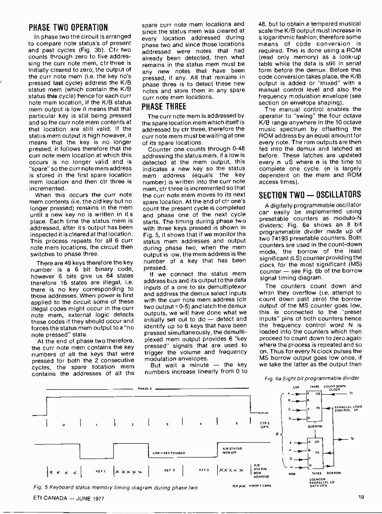
PHASE TWO OPERATIONIn phase two the circuit is arranged
to compare note status's of presentand past cycles (Fig. 3b). Ct r twocounts through zero to five addres-sing the curr note mem, ctr three isinitially cleared to zero, the output ofthe curr note mem (i.e. the key no'spressed last cycle) address the K/Bstatus mem (which contain the K/Bstatus this cycle) hence for each currnote mem location, if the K/B statusmem output is low it means that thatparticular key is still being pressedand so the curr note mem contents atthat location are still valid. If thestatus mem output is high however, itmeans that the key is no longerpressed, it follows therefore that thecurr note mem location at which thisoccurs is no longer valid and is"spare" so the curr note mem addressis stored in the first spare locationmem location and then ctr three isincremented.
When this occurs the curr notemem contents (i.e. the old key but nolonger pressed) remains in the memuntil a new key no is written in it splace. Each time the status mem isaddressed, after it s output has beeninspected it is cleared at that location.This process repeats for all 6 currnote mem locations, the circuit thenswitches to phase three.
There are 49 keys therefore the keynumber is a 6 bit binary code,however 6 bits give us 64 statestherefore 16 states are illegal, i.e.
there is no key corresponding tothose addresses. When power is firstapplied to the circuit some of theseillegal codes might occur in the currnote mem, external logic detectsthese codes if they should occur andforces the status mem output to a "nonote pressed" state.
At the end of phase two therefore,the curr note mem contains the keynumbers of all the keys that werepressed for both the 2 consecutivecycles, the spare location memcontains the addresses of all the
spare curr note mem locations andsince the status mem was cleared atevery location addressed duringphase two and since those locationsaddressed were notes that hadalready been detected, then whatremains in the status mem must beany new notes that have beenpressed, if any. All that remains inphase three is to detect these newnotes and store them in any sparecurr note mem locations.
PHASE THREEThe curr note mem is addressed by
the spare location mem which itself isaddressed by ctr three, therefore thecurr note mem must be waiting at oneof its spare locations.
Counter one counts throJgh 0-48addressing the status mem, if a low isdetected at the mem output, thisindicates a new key so the statusmem address (equals the keynumber) is written into the curr notemem, ctr three is incremented so thatthe curr note mem moves to its nextspare location. At the end of ctir one'scount the present cycle is completedand phase one of the next cyclestarts. The timing during phase twowith three keys pressed is shown inFig. 5, it shows that if we monitor thestatus mem addresses and outputduring phase two, when the mem
Iow, the mem address is thenumber of a key that has beenpressed.
If we connect the status memaddress bus and its output to the datainputs of a one to six demultiplexorand address the demux select inputswith the curr note mem address (ctrtwo output = 0-5) and latch the demuxoutputs, we will have done what weinitially set out to do - detect andidentify up to 6 keys that have beenpressed simultaneously, the demulti-plexed mem output provides 6 "keypressed" signals that are used totrigger the volume and frequencymodulation envelopes.
But wait a minute - the keynumbers increase linearly from 0 to
PHASE 2
Igg
2
KEY 1 Ix XX x
3 I 4 I 5
LOW KEY PRESSED
48, but to obtain a tempered musicalscale the K/B output must increase ina logarithmic fashion, therefore somemeans of code conversion isrequired. This is done using a ROM(read only memory) as a look -uptable while the data is still in serialform before the demux. Before thiscode conversion takes place, the K/Boutput is added or "mixed" with amanual control level and also thefrequency modulation envelope (seesection on envelope shaping).
The manual control enables theoperator to "swing" the four octaveK/B range anywhere in the 10 octavemusic spectrum by offsetting theROM address by an equal amount forevery note. The rom outputs are thenfed into the demux and latched asbefore. These latches are updatedevery n uS where n is the time tocomplete one cycle. (n is largelydependent on the mem and ROMaccess times).
SECTION TWO - OSCILLATORSA digitally programmable oscillator
car easily be implemented usingpresetable counters as modulo -Ndividers; Fig. 6a shows an 8 bitprogrammable divider made up oftwo 74193 presetable counters. Bothcounters are used in the count -downmode, the borrow of the leastsignificant (LS) counter providing theclock for the most significant (MS)counter - see Fig. 6b of the borrowsignal timing diagram.
The counters count down andwhen they overflow (i.e. attempt tocount down past zero) the borrowoutput of the MS counter goes low,this is connected to the "presetinputs" pins of both counters hencethe frequency control word N isloaded into the counters which thenproceed to count down to zero againwhere the process is repeated and soon. Thus for every N clock pulses theMS borrow output goes low once, ifwe take the latter as the output then
Fig. 6a Eight bit programmable divider
CTR 2
0/P'S
K,EI STATUS
MEM 0/P
KEY 2 KEY 3 I XX X X XK/8
STATUSMEMADDRESS
LS8
A .A CD
B
D D
G C
H D
74193 COUNT DOWNCLOCK
MSB
B
PE
BORROW
A CD
PE
PARALLEL LOADCONTROL UP
74193 BORROW
Fig. 5 Keyboard status memory timing diagram during phase two
ETI CANADA - JUNE 1977
XXXX DON'T CARE
COUNTERPARRELLEL LDDATA UP'S
19

MODULE N DIVIDER
( 2 ) ) I ( 0 ) I ( 16 ) 1
fin
COUNT DOWN CLK
CTR 0/Pn1
n2
BORROW 0/P
01
N n2
n1
PHASECOMPARATOR
7 n2
MODULE N
DIVIDER
wt
L OW -PASSFILTER
VOLTAGECONTROLLEDOX - VCO
to
Fig. 6b Borrow output timing diagram for 74193 up/down counter Fig. 6c Basic phase -locked -loop frequency multiplier
its frequency will be fo=f1/N and is inthe form of a narrow pulse train.
For N=8 bits 14N255, the range ofcontrol of output frequency dependson the range of N and hence thenumber of counters used, e.g. three74193's gives us an N of 12 bitstherefore 1N.E.4096.
An extension of (a) is the phaselocked loop freq. divider/multiplier(b) shown in Fig. 6c. There is plenty ofliterature available on phase lockedloops so we will not describe thecircuit except to say that the VCOoutput frequency = n, fin/n2. Thismethod is obviously more expensivethan (a) since you need two dividersplus the phase lock loop circuitry.
Note: We mentioned in section onethe need for a ROM to convert thelinear K/B number to a logarithmicone, it should be obvious thatdifferent conversion tables arerequired for (a) or (b).
Fig. 7a Fundamental sinewave split into16 samples
Fig. 7b Second harmonic obtainedby multiplying ROM addresses by two
SECTION THREE TONE SHAPING
Most of the conventional musicsynthesisers today use voltagecontrolled filters to modify theharmonic content of a predefinedcomplex waveform (e.g. a square ortriangular wave) in order to achievethe required tone. To use a direct
digital equivalent would of courserequire a digital filter, however aprogrammable filter over thefrequency range required would bequite complex and very expensive.
In this multiphonic system we areabandoning this method of synthesis(called subtractive synthesis) andadopting an additive synthesismethod, i.e. start with a sinewave atthe fundamental frequency, generatethe harmonics required and add allthe waveforms together to producethe final complex waveform.
ADDITIVE SYNTHESIS
The following section demon-strates the principles involved in adigital implementation of additivesynthesis.
CLK
fIn
4 BITCTR
ADDRESS
= number of samples in fundamentalharmonic number.
The act of quantising a sinewaveproduces undesirable frequencycomponents as the spectrograph inFig. 10 reveals. Besides the funda-mental frequency we also getcomponents derived from thesampling frequency Fs i.e. fre-quencies F,=Fs-F, and F2=Fs+Fo. Theeffect is very much like that of asuppressed carrier waveform offrequency Fs "modulated" with asignal of frequency F4, F. and F2 beingthe resultant sidebands, this effectalso occurs at harmonics of Fs bylower in amplitude e.g. we obtainfrequencies of 2Fs-F0 and 2Fs+F, etc.Since all these frequencies are higherthan the fundamental they can beremoved with a low pass filter.
ROM 0/P D/A to
Fig. 8 Generation of a "quantised- sinewave
A sinewave split up into 16 samplesnumbered 0-15 is shown in Fig. 7a, ifthe sinewave amplitude at eachsample point is stored in 16consecutive locations of a ROM andthe ROM addressed by a four bitcounter counting continuously (Fig.8), then the output of a D/A convertorconnected to the ROM outputs wouldgive a "quantised" version of theoriginal sinewave.
If we now modify the ROM addressby multiplying the counter output bytwo (i.e. during the first time slotaddress the ROM at location 2
instead of 1, then during the secondtime slot address the ROM at locationfour instead of 2 and so on) Fig. 7bshows us that the original sinewavefrequency (i.e. fin) is doubled i.e. weget the second harmonic of Fo,however whereas the fundamentalconsisted of 16 samples the secondharmonic consists of only 8 samples.Likewise if we multiply the ctr outputsby three we will obtain the thirdharmonic, containing 16/3 samples/cycle. The number of samples/cycle
However with a constant samplingfrequency, as the fundamentalfrequency is increased the component Fs-Fo will move nearer to thfundamental until when Fs=F, the twofrequencies coincide and cannot beseparated by the filter, therefore thetheoretical minimum sampling rate isFs=2F, i.e. two samples/cycle, a morepractical limit is three or even foursamples/cycle.
Therefore if we intend to generate 6harmonics from the fundamentalfrequency we need at least 18samples in the ROM - number ofharmonics required multiplied by theminimum number of samples for anacceptable sinewave (=6X3), themore samples in the ROM, the betterthe resultant sinewave.
MULTIPLICATIONA simple method of generating a
complex waveform consisting ofthree equal amplitude harmonics andthe fundamental is shown in Fig. 9.this would be quite effective but
20 ETI CANADA - JUNE 1977

.11191..4111,
11111.
am.
daoAIM
*Ma
41111Y
maim.
ana
MN/
WWI
A "quantised" sinewave formed by sampling a sinewave offrequency Fo at a sampling of frequency Fs.
wasteful of ROM, since all the ROM'sare identical it would be muchcheaper to use one ROM for thesinewave values and time sequencethe harmonic additions, the multi-plications to modify the ROMaddress can also be performed in aROM.
The concept of multiplicationusing a ROM is quite simple, if wewant to multiply two 2 bit numberstogether there are only 16 possibleanswers (since there are fourpossible multiplier values and fourpossible multiplicand values) there-fore if we make the multiplier two bitsof a ROM address and the multi-plicand the other two bits of theaddress we end up with four bitaddress giving us 16 ROM locations.All we have to do is program eachROM location with the correctanswer for that particular address;e.g. four bit address = 11 decimal --1011 = (10)(11) = 2 X 3 = 6 decimal =0110 therefore location 11 isprogrammed with 0110. Thisprinciple can be extended for any noof address bits and gives us a fastmethod of multiplication (ordivision).
Referring to Fig. lithe ctr outputs
lin CTR0 16
inutrinsim111111111111119111111
11111MIMINIMIN Mir6 Iminullii
1 amilinommuu1 mummananim11111111111111111111111111111111, ,, r n .o a 19 MI. ,..Irg4....,
BLIP
fo
Fl Fs -Fo
I
I F2
j
Fs I
F0 Fs
Fs -Fo
Fo
3Fs -Fo
3F5
3Fs Fo
Fig. 10 Part of the frequency spectrum of the sinewave of the previousphotograph. Note the "suppressed carrier double sideband"effect at the sampling frequency and its harmonics. Also note the"blips" after F., these are harmonics of F, that are also producedby quantising a sinewave, !hey are low enough in amplitude to beignored if an 8 bit binary number is used to represent thesinewave amplitude at each sample.
provide a four bit address field to theX ROM the harmonic numberprovides a two bit address field to thesame ROM which is thus pro-grammed with the result of themultiplication of the two fields.
AMPLITUDE CONTROLThe sinewave ROM is modified this
time with the introduction of aharmonic amplitude control, thisenables us to multiply the originalsinewave sample value by a constant(K). Thus by using a different value ofK (via mux A) for each harmonic wecan control the amplitude levels ofeach harmonic -a four bit K addressfield gives us 16 levels of amplitudecontrol.
The ctr counts through its 16 statesas before, each sample of the
Fig. 9 Basic complex waveform generation
X2
ROM
ROM
ROM
ROM
EACH ROM ISIDENTICAL AND CONTAINS1 SINEWAVE CYCLE
ADDER
F.
waveform consists of four "passes" ofthe circuit.
Pass One The accumulator (acc)is cleared, the harmonic numbertwo field = 00 (X1) therefore the XROM outputs the requiredamplitude value which is addedto the 0 (the contents of the acc)and the result stored in the acc.Pass Two The harmonic numberis incremented to 01 (X2) i.e. XROM outputs = ctr outputs X2,the sinewave value is multipliedK2 and the result is added to theprevious result (contents of acc)and the new result stored in theacc.
This process is repeated for Passesthree and four, each time the accbeing "topped up" until after thefourth pass it contains the totalcontributions of all four frequencycomponents, this value is thenlatched in the output buffer andoutputed to the D/A convertor. Thewhole process is then repeated forthe next sample and so on.
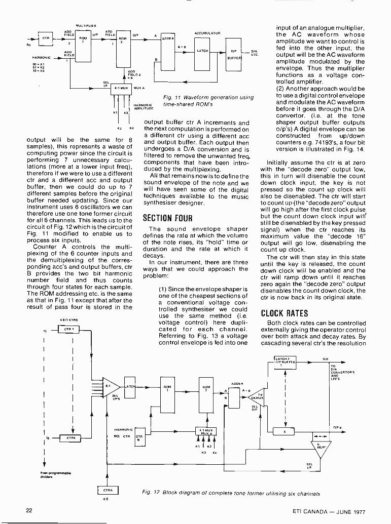
Each sample therefore consists of 8ROM accesses plus the propagationdelays of the latches, mux and theadder, using high speed logic andbijolar ROM's the time/sample<1 microsecond. If we limit ourinstrument top freq to 8kHz then thehighest ctr clock period =125/16pSor 8,,S. Since one sample takes 1 µS,the output buffer will contain thesame result for 8 samples at thehighest input freq (because the ctr
ETI CANADA - JUNE 1977 21
lin
CTR
MULTIPLIER
ADDFIELD
HARMONIC
00 = X101 = x210=X3
ADDFIELD
OM
ADD0/P FIELD
SELI/P
RO0/P A
ADD!,,ELD 2
1 MUX I MUX A
K3
K2 KB
output will be the same for 8samples), this represents a waste ofcomputing power since the circuit isperforming 7 unnecessary calcu-lations (more at a lower input freq),therefore if we were to use a differentctr and a different acc and outputbuffer, then we could do up to 7different samples before the originalbuffer needed updating. Since ourinstrument uses 6 oscillators we cantherefore use one tone former circuitfor all 6 channels. This leads us to thecircuit of Fig. 12 which is the circuit ofFig. 11 modified to enable us toprocess six inputs.
Counter A controls the multi-plexing of the 6 counter inputs andthe demultiplexing of the corres-ponding acc's and output buffers, ctrB provides the two bit harmonicnumber field and thus countsthrough four states for each sample.The ROM addressing etc. is the sameas that in Fig. 11 except that after theresult of pass four is stored in the
4 BIT CTRS
ti CTR I
CTR6
from programmabledivider.
F-
6.1
SELI/P S
ADDER
ACCUMULATOR
A BLATCH 0/P
BUFFER- °4.
Fig. 11 Waveform generation usingHARMONIC time-shared ROM'sAMPLITUDE
C
HARMONIC
NO. CTR
output buffer ctr A increments andthe next computation is performed ona different ctr using a different accand output buffer. Each output thenundergoes a D/A conversion and isfiltered to remove the unwanted freq.components that have been intro-duced by the multiplexing.
All that remains now is to define thesound envelope of the note and wewill have seen some of the digitaltechniques available to the musicsynthesiser designer.
SECTION FOUR
The sound envelope shaperdefines the rate at which the volumeof the note rises, its "hold" time orduration and the rate at which itdecays.
In our instrument, there are threeways that we could approach theproblem:
(1) Since the envelope shaper isone of the cheapest sections ofa conventional voltage con-trolled synthesiser we coulduse the same method (i.e.voltage control) here dupli-cated for each channel.Referring to Fig. 13 a voltagecontrol envelope is fed into one
BR
ROM ROM2 A
4:1 MUXMUX A
El K3
K2 K4
ADDER
AFB
input of an analogue multiplier,the AC waveform whoseamplitude we want to control isfed into the other input, theoutput will be the AC waveformamplitude modulated by theenvelope. Thus the multiplierfunctions as a voltage con-trolled amplifier.(2) Another approach would beto use a digital control envelopeand modulate the AC waveformbefore it goes through the D/Aconvertor. (i.e. at the toneshaper output buffer outputso/p's) A digital envelope can beconstructed from up/downcounters e.g. 74193's, a four bitversion is illustrated in Fig. 14.
Initially assume the ctr is at zerowith the "decode zero" output low,this in turn will disenable the countdown clock input, the key is notpressed so the count up clock willalso be disenabled. The ctr will startto count up (the "decode zero" outputwill go high after the first clock pulsebut the count down clock input will'still be disenabled by the key pressedsignal) when the ctr reaches itsmaximum value the "decode 16"output will go low, disenabling thecount up clock.
The ctr will then stay in this stateuntil the key is released, the countdown clock will be enabled and thectr will ramp down until it reacheszero again the "decode zero" outputdisenables the count down clock, thectr is now back in its original state.
CLOCK RATESBoth clock rates can be controlled
externally giving the operator controlover both attack and decay rates. Bycascading several ctr's the resolution
16DEMUR
SEL0/P
LATCH 20/P BUFFER
0/P
6
TOD/ACONVERTOR'SANDLPF'S
0/P 6
M
SELI/P
CTRA
06
Fig. 12 Block diagram of complete tone former utilising six channels
22 ETI CANADA - JUNE 1977

The fundamental component and the first "set"of "sideboard"components. If the sampling frequency is kept constant and thefundamental frequency increased.
of the envelope can easily beexpanded. Such an envelope can alsobe used as the K/B freq modulationenvelope, as for the envelopeshapers, one is required per noteoutput, see Fig. 4. The six envelopeoutputs are fed into a six to one muxwhich is addressed by the notenumber (The curr note mem addressduring phase two of the K/B decoderroutine), the mux output is "mixed"with the K/B number and the manualsetting. Therefore each note is"mixed" with its own envelope valuefor each K/B decoder cycle.
We have already seen how a ROMcan be programmed as a multiplierusing the multiplier and the multi-plicand as the ROM address fields,thus if we connect the volumemodulation envelope outputs as oneaddress field and the digitisedwaveform as the other we can
1111111111111'111111
eivell111111111,1M11
9 iii
a
F
This shows how the component Fs - F, and F,-, move closertogether until, at the limiting frequency of Fs = 2F,, they willcoincide.
program the ROM accordingly tobehave as a digitally controlledamplifier. We then perform the D/Aconversion and filtering to the outputof the ROM and then feed theanalogue waveform directly into theaudio section of the synthesiser.
The final approach is a mixture ofdigital and analogue circuitry andprobably is the cheapest toimplement.
A simple n bit switched laddernetwork DlA convertor is shown inFig.15. The state of each switch isdependent on whether that particularbit is a 1 or 0 (1=V ref, 0=ground).
The analogue output of the D/A isproportronal to the (digital input) XVref, this if we connect our digitised
COUNT
74193
AATTACK _fin_ UP
CLK
DELAY CLK COUNT
B
DOWN C
"DECODE 16"
TR 0/P'S
KEY PRESSED KEY PRESSEDSIGNAL FROM K/B DECODER SIGNAL
Fig. 14 A simple four bit digital envelope shaper
Fig. 15 Simplified n -bit switched resistor D/A convertor
Vrel
2R
AC WAVE FORM0/P FROMD/A 8, LPF
waveform to the digital inputs of sucha convertor and an analogue controlenvelope to the V ref input we canaccomplish our D/A conversion andenvelope shaping at the same time.
So there we have the basicconcepts and circuit ideas behind acomplete and viable system. Theywill at least show how digitaltechniques can be applied to what isessentially an analogue system andthey may well encourage variousreaders to "have a go". The author isworking on a practical unit and wemay be able to present further detailsin due course - should any readershave similar projects in mind or inoperation we would be pleased tohear of their experiences.
"DECODE
ANALOGUE MULTIPLIER
NORMAL VOLTAGEENVELOPE
/fNfENVELOPE SHAPEDWAVEFORM
Fig. 13 Conventional method of envelope shaping
R
VOui
140161DIGITAL I/PCONTROLS SWITCHSTATES
23ETI CANADA - JUNE 1977
ALARMS
Contents
Basic AlarmPhoto Intruder AlarmIntruder AlarmPhoto Electric RelayLow Temperature/Lights outTemperature SensorCoolant levelWater LevelElectronic LockCar Battery WatchdogSimple Car AlarmSimple Lock
AMPLIFIERS &PREAMPLIFIERSHigh Input ImpedanceHigh Impedance BufferLow Output ImpedanceHigh Input ImpedanceLow Frequency ExtenderVirtual Earth PreampIC Tape Head PreampSimple Stereo Tape Player2.5 Watt20 Watt Slave10 WattLoudspeaker MicrophoneVoltage Controlled AmpWide Band AmplifierVideo Power AmpBroadband Amp
SIGNAL PROCESSORS
Fuzz BoxGuitar FuzzFuzz BoxWaa WaaDisco AutofadeSimple AutofadeInformation TransferOptical Pulse ConditionerTV Sound PickoffCracklefree PotentiometerVoltage to FrequencySine to Square WavePrecision AC to DCVoltage ProcessorUniversal MeterDouble PrecisionFast Half WaveSimple ChopperNoise Rejecting SCR TriggerPhase Shifter
SIGNAL GENERATORS
SimpleVariable Duty cycleFast EdgeFETImproved MultivibratorVariable Duty cycleStable R CCheap (CMOS)Simple TTL XTALUncritical XTALPulseZero CrossingSimple PulseNeedle PulseStable Linear SawtoothZenerNoisePink
The first in a new seriesof 'ideas books' for the experimenter
Simple RelaxationTriangle with independent slopeExponentialWiderange MultivibratorMultiple WaveformLinear SweepStep FrequencyBeeper7400 SirenSimple SirenShip SirenTwo ToneToy SirenKojak. Startrek. Z CarsSound EffectsSound Effects
FILTERS
BandpassLow 8 High PassRejection NotchBandpassCartridge EC RumbleHum StopperTape Hiss ReductionSimple Crossover
DIGITALThermometerHeads or TailsBinary CalculatorVoltmeterSeven Segment to DecimalDieRandom BinaryCMOS DieMultiplexer HintsLearning MemoryCMOS Clock
POWER SUPPLIES
ConstantTemperature StableConstantVoltage ControlledPrecision Voltage DividerDual PolaritySimple BalancedVoltage DividerLow RegulatedShort Circuit ProtectedSimple TTL SupplyZN414 SupplyStable ReferenceTransformerless InvertorDC to DC ACVoltage MultiplierAutomobile ConvertorShaver AdaptorDC -DCHigh Voltage From BatteryVariable ye or -ve outputSimple12V from Battery ChargerBucket RegulatorAdjusting Zener VoltageVariable ZenerZener Boosting of RegulatorsHigh PowerElectronic FuseBetter FuseRegulator & FuseFast ActingSCR CrowbarVoltage PolarityNI CAD DischargeCurrent Limiting
TEST
Diode CheckerGO/NO GO Diode TesterZener CheckGO/NO GO Transistor TesterQuick JFET TestCurrent Gain TesterBasic Transistor TesterSimple Transistor/SCRSCR TesterCrystal CheckCrystal CheckerGood/Bad Battery TesterBattery TesterOp -Amp TesterOp -Amp CheckerCheap Logic Probekudible TTL ProbeAudible Slow PulsesLogic ProbeLogic AnalyserI and 0 Display ProbeSimple High ImpedanceVoltmeterAudio/RF TracerThermocouple ThermometerMetering Stabilised suppliesSimple Frequency Meter
TIMERS & DELAYS
Low Standby Drain741 TimerSelf Triggering TimerPulse TimerPulse DelayVoltage Controlled MonostableSequential RelaysDoor Chime Delay
SWITCHING
Touch Triggered &stableTouch Sensitive SwitchElectronic SwitchSound Operated 2 WaySPST Switch Flip FlopTwo Signals on one Wire
INDICATORS
Line -o -Light3 Step LevelLight LevelBargraph DisplayFuse FailureBlown FuseBack Up LampDC Lamp FailureFM Tuner StationCurrent FlowDisco Cue
FLASHERS
Dancing LightsLow Frequency Strobe
FlasherUltra Simple
POWER CONTROL
LDR Mains ControlFloodlamp ControlZero Crossing Sy%Train ControllerLow Differential ThermostatSimple Temperature ControlFull Wave SCR Control
AUTOMOBILE
Brake Lamp FailureCourtesy Light DelaySimple Hazard LightLight Extender & ReminderFour Way FlasherHeadlamp DipperWiper DelaySuppressed Zero VoltmeterRev Counter/TachometerAuxiliary Battery
DETECTORS &COMPARATORS
Peak Detect & HoldWindow DetectorPeak ProgramPositive PeakReaction Comparator
RADIO FREQUENCY
Crystal Marker100 kHz MarkerRF VoltmeterRF DetectorLED RF IndicatorRF Amplifier ProtectionFET-RadioOp -Amp Radio
MISCELLANEA
Phase Locked LoopTouch DoorbellPhase Lock ControlAudio MixerVirtual Earth MixerPlop EliminatorLoudspeaker ProtectionDigital Capacitance ProbeDigital Tape Recorder AdaptorBreakdown Diode SubstitutionDual Function ChargerDual Mode Amp
Capacitor SubstitutionElectronic CapacitorSpeeding Up DarlingtonsShutter SaverThyristor SensitivitySound Operated FlashStrength TesterLogic Noise Immunity
TIPS
Identifying 74 SeriesSupply PinsSoldering IC'sTinning With Solder WickPCB StencilsFront Panel FinishDIL DrillingFluorescent StartingAvoiding Insulated Heat SinksTTL Mains InterfaceBoost Your MainsHigh Resistance on Low MetersHigh Voltage ElectrolyticsTransistor IdentificationTemplate & Heat Sink forPower TransistorsTransistor SocketSolder Flow ProblemsOdd Resistor ValuesResistors in parallelCMOS DIL HandlingIdentifying Surplus ICSExtending Battery LifeBattery SnapsPower Supply or BatteryBattery CheckingMuck RemoverTransformers in reverseLoudspeaker CheckingImproving UJT LinearitySignal TracerCrystal EarpiecesCheap VaricapsZener Lifts Capacitor Rating
DATA
741 Op -Amp DataBC 107-109 DataBC 177-179 DataCMOS & TTL Date2N3055 DataMJ2955 DataBipolar Data TablesBipolar FETs RectifiersDiodes Pinouts Zener Misc
24 ETI CANADA - JUNE 1977

N Nalg1511by Peter Sydenham
SCIENCE PROVIDES US WITHknowledge about existence. It is basedon a procedure of collecting facts whichare placed into apparently logicalgroupings in order to lead to stage twoof scientific method - the realisation ofone or more hypotheses. Man's imagin-ative powers then enable ideas aboutthese facts to be "tried out" in themind. (The mind creates what are called'models'). After a brain -storming sessionsome ideas emerge about the collectedfacts. These are likely contenders ofgeneralised models that will describemany seemingly different ideas by oneunified concept. Figure 1 depicts thisprocess.
Having hit upon an hypothesis it is
then tested by performing experimentsupon it to see if more examples thatwould appear to also be correct areindeed allowed for. The hypothesis, aslong as it is found satisfactory, is thenheld as current and applicable until anew case emerges that is not describedadequately enough by it. The scientificprocess is then begun again to find anew hypothesis that is better than theearlier one.
Old hypotheses are not necessarilyuseless. They find their use in limitedcases. We are quite satisfied in every-day life to regard mass as a constantentity but on some special occasions,in the design of some cathode raydevices for example, mass must beconsidered as being convertible toenergy. Einstein's work predicted thatconversion process.
New hypotheses produce new ideasfor technology to take up and apply.Once it was known that the atom wasdivisible, scientists sought to split itfurther.
This brings us to the role of tech-nology in the development of ideas.Technology and engineering is the broaddiscipline that devises machines andstructures that do not exist as such innature but using resources that areavailable naturally - see Fig. 2.Machines provide us with power con-version, with mechanisms and withmeasuring and information tools.
I
1. OBSERVE
COLLECT FACTS
(MANY BUTTERFLIES OFCERTAIN CHARACTERISTICS)
2. THINK
FORM HYPOTHESIS
3. OBSERVATION
TEST HYPOTHESIS
IIBIG SPOTTED AND LITTLE I (EXPERIMENT BREEDSSPOTTED BUTTERFLIES BREED MIXED SPOTS, THEREFORETO ..oDUCE MIXED SPOTS) HYPOTHESIS CORRECT.)
Fig. I. Diagram showingsieges of the scientificmethod Science producesknonfedge.
Technology is a sister requirement ofscientific pursuit - inseparable partnersin progress, each affecting the other'sprogress at varying degrees with time.Figure 3 shows an example of thisinteraction.
One often -seen mis-statement is thatscientists build the so-called scientificmachines. "Scientists put a package onMars is the greatest scientific achieve-ment yet made by man". If it had beena failure then it would have been due toengineering failure! The Mars' probe israther the greatest technologicalachievement.
It is important to see how muchtechnology compared with how muchscience goes into a manufacturedproduct for this helps us predict whennew ideas will come into practical use.
There is, however, another aspect totechnology. Many lifestyle changingideas do not occur as the result ofapplying science in a systematic manner.In fact many valuable machines andideas arrive by way of an unknown,often poorly trained, inventor whoapplies an uncommonly good amount ofcommon-sense to solving an immediateproblem.
But society itself is also a stronginfluence on the application of newideas. Somehow a new idea appears outof place. We now accept eyeglasses asnormal technology, but think how aperson wearing a filtering false nose(a possibility for reducing hay -fever
allergies) would be received. Organtransplants were, and still are to someextent, opposed. Test-tube babies arecurrently controversial.
Many problems of society could besolved more easily if we were preparedto accept change and make whatappears at the time to be sacrifice morewillingly. We have seen over the past twoyears a strong swing toward the smallercar. Air travel is now cheaper than by sea- the reverse of a decade ago. A trans -world telephone call now gives moremessage content than a telegram for thesame price.
This introduction and the previouspart of this study sets the scene forwhat I see could be some aspects offUture living. I possess no crystal ball; I
claim no extra sensory perceptionability, nor do I have a pact with themaker or devil! What is given now iscomposed from studying the past trendsand extending them into the future, thisbeing sprinkled with some personalideas of myself and others.
GETTING ABOUT IN THE FUTUREAlthough there have been instances
in history where knowledge of man hasbeen lost by chance or by politicaldecree (the 1930's burning of thebooks in Germany) - technologicalchange has continued to advance inall civilisations (albeit sometimes ex-tremely slowly). It is most unlikelythat the "alternative" communes we
ETI CANADA - JUNE 1977 25
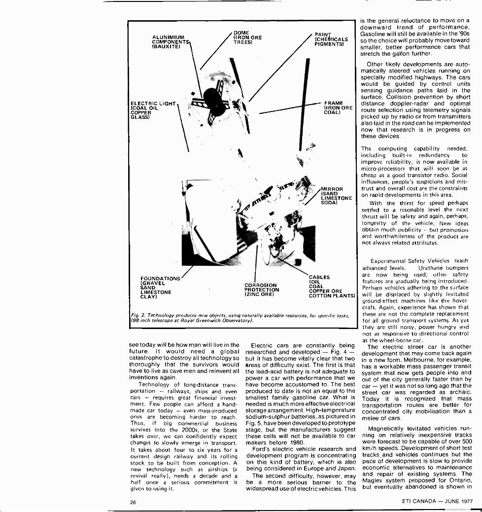
ALUNIMIUMCOMPONENTS(BAUXITE)
ELECTRIC LIGHT(COAL OILCOPPERGLASS)
FOUNDATIONS(GRAVELSANDLIMESTONECLAY)
DOME(IRON ORETREES)
CORROSIONPROTECTION(ZINC ORE)
PAINT(CHEMICALSPIGMENTS)
FRAME(IRON ORECOAL)
MIRROR(SANDLIMESTONESODA)
CABLES(OILCOALCOPPER ORECOTTON PLANTS)
Fig. 2. Technology produces new objects, using naturally available resources, for specific tasks.(98 inch telescope at Royal Greenwich Observatory).
see today will be how man will live in thefuture. It would need a globalcatastrophe to destroy all technology sothoroughly that the survivors wouldhave to live as cave men and reinvent allinventions again.
Technology of long-distance trans-portation - railways, ships and evencars - requires great financial invest-ment. Few people can afford a hand-made car today - even mass-producedones are becoming harder to reach.Thus, if big commercial businesssurvives into the 2000s, or the Statetakes over, we can confidently expectchanges to slowly emerge in transport.It takes about four to six years for acurrent design railway and its rollingstock to be built from conception. Anew technology such as airships (a
revival really), needs a decade and ahalf once a serious commitment is
given to using it.
Electric cars are constantly beingresearched and developed - Fig. 4 -but it has become vitally clear that twoareas of difficulty exist. The first is thatthe lead -acid battery is not adequate topower a car with performance that wehave become accustomed to. The bestproduced to date is not an equal to thesmallest family gasoline car. What isneeded is much more effective electricalstorage arrangement. High -temperaturesodium -sulphur batteries, as pictured inFig. 5, have been developed to prototypestage, but the manufacturers suggestthese cells will not be available to carmakers before 1980.
Ford's electric vehicle research anddevelopment program is concentratingon this kind of battery, which is alsobeing considered in Europe and Japan.
The second difficulty, however, maybe a more serious barrier to thewidespread use of electric vehicles. This
is the general reluctance to move on adownward trend of performance.Gasoline will still be available in the '90sso the choice will probably move towardsmaller, better performance cars thatstretch the gallon further.
Other likely developments are auto-matically steered vehicles running onspecially modified highways. The carswould be guided by control unitssensing guidance paths laid in thesurface. Collision prevention by shortdistance doppler-radar and optimalroute selection using telemetry signalspicked up by radio or from transmittersalso laid in the road can be implementednow that research is in progress onthese devices.
The computing capability needed,including built-in redundancy toimprove reliability, is now available inmicro -processors that will soon be ascheap as a good transistor radio. Socialinfluences, people's suspicions and mis-trust and overall cost are the constraintson rapid developments in this area.
With the thirst for speed perhapssettled to a resonable level the nextthrust will be safety and again, perhaps,longevity of the vehicle. New ideasobtain much publicity - but promotionand worthwhileness of the product arenot always related attrihutes.
Experimental Safety Vehicles reachadvanced levels. Urathane bumpersare now being used; other safetyfeatures are gradually being introduced.Perhaps vehicles adhering to the surfacewill be displaced by slightly levitatedground -effect machines like the hover-craft. Again, experience has shown thatthese are not the complete replacementfor all ground transport systems. As yetthey are still noisy, power hungry andnot as responsive to directional controlas the wheel -borne car.
The electric street car is anotherdevelopment that may come back againin a new form. Melbourne, for example,has a workable mass passenger transitsystem that now gets people into andout of the city generally faster than bycar - yet it was not so long ago that thestreet car was regarded as archaic.Today it is recognized that masstransportation routes are better forconcentrated city mobilisation than amelee of cars.
Magnetically levitated vehicles run-ning on relatively inexpensive trackswere forecast to be capable of over 500km/h speeds. Development of short testtracks and vehicles continues but thepace of development is slow to provideeconomic alternatives to maintenanceand repair of existing systems. TheMaglev system proposed for Ontario,but eventually abandoned is shown in
26 ETI CANADA - JUNE 1977

Fig.7 . Remember that prototypes arequicker to materialise than servicevehicles. For inter -city distances in bigcountries we need a speed of about 500km/h to make journeys sufficientlyshorter than the current alternative ofthe car or train. Airflight time isbecoming limited by cost and airportturnaround time - door to door andwith no connections to make, a 1000 kmdistance takes about three hours.Maglev inter -city systems, however,now must be designed in light of a newsocial barrier not obviously in existencefive years back - they need greatquantities of power to run at such highspeeds. Societal values no longer ignoresuch demands on resources. Superconducting Maglev systems will requirevast quantities of scarce helium - thismay limit their widespread useage.
The bicycle is good for the healthbut its slowness and effort requirementsdo not suit most people who live farfrom their workplace. A compromisebetween the bicycle and the car seemshow things should develop but socialconstants, personal comfort and theability to carry passengers and loadsrequire a wide degree of flexibility forthe future personal transport vehicle.
Moving on to transport at sea we canconfidently expect to see automaticships navigating by electronic control.Position sensing devices are sufficientlydeveloped for the task - especiallywhen the Omega navigational networkis complete across the globe. Computercontrol is quite capable of the dataprocessing needed and machinerycontrol is not extremely reliable and welldefined. Automation of ships, however,would need global acceptance of theconcept and more faith in machinery.Automatic fishing is also a realisablegoal - for we can now detect where fishare in the sea.
Fig.3 Science and technology go hand in hand helping each othercontinuously. (Computer controlled engine -testing at Cranfield).
Ship -forms may shift to surface -effectdesigns - plans were announced in theUS last year for design studies of a 100000 ton naval cruiser that could move atspeeds double those of today. Shipspeeds are decided by physicallimitations arising because of the wettedarea surface drag and the disturbancecaused as the water is physicallydisplaced by the ship's motion. Raisingspeeds above 10 knots or so demandsenormous increases in fuel con-sumption. Solutions to this are to gocompletely under like the submarine, forhis also reduces the power needed, riseout of the water on skis, or the hoverprinciple. One advantage of the latter ishat the swell and roll of sea travel isgreatly reduced. Hover ships can runtoday at speeds of 80 knots butproblems with skirt sealing in roughweather appears to be a major currentlimit on the usefulness on the open sea.The history of naval architecture,
Fig.4. The electric car can only provide satisfactory transportationfor short land tasks. This is a pleasure versi9n by ElecTraction.
howeve-, shows that ships change inonly minor ways and at a slow pace.
Finally, in the air: what will happenthere? There was once a time - just afew years ago when air travel hadbecome the pinnacle of transportcomfort and speed. But today it fails toprovide a fast enough overall journeytime because of airport regulations ofarrival before departure time, clearanceat security barriers, checking of tickets,settling of passengers and the like. Itseems, as a rule of thumb, that theactual flight time is about equal to the
Fig. 5 Na-S high temperature batteries cmstore much more power for a given weightthan lead acid cells but they will not beavailable for another five years or more.
ETI CANADA - JUNE 1977 27

sundry time involved for short inter-national flights. Plans were published inthe early seventies for cabins (ifi whichpeople were assembled) ready to beattached to the plane. In some countriessuper highways link the remote airportsfrom the city centres. Somehow theseplans did not provide the answer nowseen to be needed.
Supersonic transportation is findingdifficult acceptance, and it is just notpossible to state at present whether it isgood or bad with any degree ofcertainty. Only time will tell; hy-potheses need verification byexperiment.
The air ship is a strong contenderespecially if a design needing lesshelium were invented (certainly not onebased on hydrogen, for it is highlyinflammable when oxygen is available).The hot air balloon is thirsty for energydue to huge heat losses from the balloonsurface - new materials and processesmay provide us with an insulatedenclosure of light enough structure forthese to become viable for long flights.
Several companies have been formedto exploit commercial freight transportby airships. The idea is appealing --quiet, safe, speedy, not plagued withterrain problems and capable of loadsequalling many semi -trailer cargoes puttogether. Airships are an example ofpast design hopes being reborn due tobetter technological availability.
In the next part we will look at com-munications and entertainmentdevelopments of the future.
(To be continued . . .1
Fig.8. Maglev vehicles can provide great speeds but they will requiremuch more development and testing before they replace currentforms of railway.
DRIVER'S AIR
CUSHION (STORED)
PASSENGERS'
AIR CUSHION
(STORED)
Fig.6. General Motors' air cushion restraint system. These may theanswer to collision survival in the near future.
Fig. 7. In November 1974, the Ontariogovernment cancelled a $25 million urbantransportation development contract withthe West German firm of Krauss - Maffei. Atest track was to have been built at the CNE,using cars as pictured to the left.
28 ETI CANADA - JUNE 1977

electronics tqUalWhat to look for in the July issue:
C.B. SUPPLEMENTWe won't be teaching you the jargon or showing hundreds of tranceivers
and accessories - enough has already been published on how to use orabuse the facilities (whatever your views are).
What we will be covering are things like the advanced circuitry employedin modern rigs, taking a look at basic antenna arrangements and at some ofthe pitfalls (and how to avoid them) of C.B. installation.
The technical content of this supplement should make it of interest toeveryone, however they view the subject.
DIGITALVOLTMETER
A design which employs one :1Y2digit DV M chip as the basis of a meterwith five DC ranges and the capabilityof reading up to ± I 999V. Con-struction is further simplified by theuse of p.c. boards.
ELECTRONICS INNORTH SEA OIL
The various systems that have been developed forthe problems involved in extracting oil from theNorth Sea have been extensive. Next month we takea look at some of the problems and the technologythat has overcome them.
THE OVERLEDSimple circuit which shows when amplifier output
peaks are being "clipped" thus clearly indicating the onsetof associated distortion before it makes itself audiblyobvious.
This project can also be used as part of a larger audioitem - designed to provide better bass output from thosequality bookshelf speakers that lack the size to reproducethe lower octaves - to be published later.
ETIDOTS
0 1 2 3 4
MASTER- MIND-
* * STARS * *00011)4 3 1 0
2 5 7. 3
MASTERMINDThe board game of Mastermind,
where a colour code has to bebroken, was developed from asimilar game using a number codeand stars or dots as markers.
The original game has beenused as the basis for our electronicversion where the code andresponses are provided by the unitfor a player to break. Not only canyou challenge opponents, you canalso play on your own.
The articles described here are in anadvanced state of preparation, butcircumstances may necessitate changes inthe issue that appears.
ETI CANADA - JUNE 1977 29

MULTIMETERGUIDEHow to choose a meter to suit your needsTHE BUDDING experimenter, afterpurchasing a basic set of tools,commences building small circuits atthe earliest opportunity. Very rapidlyhe meets the situation where a circuit,as built, does not work. So what now?If all wiring has been done correctlythen it must be a faulty component -but which one? The simplest way tofind out is to use a meter to measurevoltages around the circuit.
Thus the first instrument that anelectronics experimenter will buy willbe some kind of multimeter capable ofmeasuring the common ranges ofvoltage, current and resistance foundin usual circuitry.
Upon investigating what is availablethe experimenter discovers thatmultimeters range in price from simpleanalogue meters at $8 to sophisticated,highly -accurate digital instrumentscosting several hundreds.
The experimenter must ask himself -which is the most suitable for his classof work? Is it really necessary to spendseveral hundreds of dollars? Are $8
multimeters worth having at all?In this article we examine the factcrs
which must be considered whenselecting a multimeter in order tosatisfy the conflicting requirements ofminimum expense and suitability.
When selecting a multimeter thefollowing factors are of importance:
Input impedanceAccuracyResolutionRuggednessNumber of rangesFrequency responsePortability.
INPUT IMPEDANCEA multimeter must have as high an
input impedance as possible if thecircuit under test is not to be severelyloaded. Loading leads to substantialerrors in the measurement and, ifsevere, may even damage components.
The input impedance of analoguemeters is usually expressed in ohmsper volt. Thus the impedance dependson the voltage range selected. Typical
THE MOVING -COIL METER
,,PPiPP
r,\N
Fig. A.
If an electromagnetic coil issuspended in the field of a
permanent magnet, it will becaused to rotate, whenenergized, by a forceproportional to the energizingcurrent.
In the moving -coil type ofmeter, as Fig.A shows, the fieldof the permanent magnet isarranged to pass across a
cylinder in which hangs the coilof the meter. A fine spiraltension -spring restrains the
rotation by providing a linearlyincreasing torque as the coilrotates. Attached to the coil is apointer that moves across a
scale, thus indicating current.
As the number of turns is
increased, to improve sensitivity,the designer must use finer wireto keep the mass of the coilsmall. As a consequence of thisrequirement, sensitive metersusually have a higher resistance,and are more delicate.
inexpensive meters have impedances of1000 to 100,000 ohms per volt. Thuswhen measuring voltage a multimeteris in effect a resistor in parallel withthe resistor (across which the voltage isbeing measured) within the circuit andit reduces the effective value of both -to something lower than the value ofeither. Thus, as a voltmeter is in effecta resistor, connecting it across a circuitwill inevitably change the resistance ofthat circuit, and the meter must shuntcurrent away from the circuit.
This brings us back to the reason forquoting the sensitivity of voltmeters inohms per volt. Multiplying thesensitivity by the fsd range in use,gives the resistance of the meter circuitthat will be shunting the component.Cheaper multimeters will havesensitivities ranging from as low as1000 S2/volt to as high as 100k 2/voltTo illustrate loading effects, consider
the circuit in Fig.1. By Ohms law weknow that the voltage between pointsA and B is 0.75 volts.
Now let us see what happens whenwe use a 1000 ohms/volt meter on the1 volt range to measure this voltage.The 1000 ohms of the meter in
30 ETI CANADA - JUNE 1977

parallel with R2 will produce a
combined value of 500 ohms. Thus thevoltage read by the meter will be 0.5volts instead of 0.75 volts - an errorof 33 per cent!
It is the degree of this shunting effectthat is important - in theory it cannever be completely avoided, for some
energy must flow into the measuringsystem from that being measured. Inelectronic measurements the rule ofthumb is that for accuracy, theresistance of a voltmeter should be atleast ten times that of the circuit - ahundredfold is better still.
However with the simple moving -coil
10, 150
JB
MOO.
250.
50* r
0212 r 0,90,
typical of the inexpensivemultimeter available this1000 ohm/volt unit is suitablefor general electrical work.
When using any meter withswitched ranges, always startoff by selecting a meter rangemuch higher than your es-timate of the quantity to bemeasured.This precaution safeguards themeter should the quantity bemuch larger than expected.
type of meter a higher inputimpedance also requires a delicatemeter movement which is relativelyeasily damaged. A good compromisewould seem to be a meter having anohms/volt rating of between 10 000and 50 000.
In more expensive meters - thoseemploying electronic amplifiers andthose using digital techniques, inputimpedances are usually at least onemegohm and hence loading of thecircuit is seldom a problem.
ACCURACYThe typical cheap multimeter has an
accuracy of the order of 3 to 5% andthis is further reduced by parallaxreading errors. Better quality analogueinstruments have 1% accuracy andmirror backed scales to reduce parallaxreading errors.
Digital multimeters are at least 1% orbetter, with 0.2% being typical.Sophisticated units costing severalthousand dollars may well haveaccuracies down to 0.001%. The wayaccuracy for a digital meter is quotedis far from being as simple as givenhere, but for our present purposes thesimple statement given suffices.
As to what accuracy is needed, it is
seldom that an experimenter, even oneat fairly advanced level, needs anaccuracy better than 1% and, mostly,even the 3 to 5% of a simple meter isgood enough. So don't get carriedaway by accuracy, if you can afford1% or better - great. But you will notbe too badly off if you can't.
1.5V
1000(_2'VOL 1METER ON1 VOLT RANGE
R11000i2
R2100(h1
Fig. 1. Meter loading of the circuitcan drastically increase reading error.
ETI CANADA - JUNE 1977 31

MULTIMETER GUIDETAUT BAND SUSPENSIONSYSTEM
Pointer
TautBand
ShockAbsorber
Tension Spring
ZeroAdjustor
MovingCoil
Better quality analoguemultimeters usually employ ataut band suspension system inthe meter movement. Thissystem, although more
expensive, has several importantadvantages over conventionalmoving coil movements.The movement still employs
the moving coil principle butnow the coil is suspended bymeans of a platinium alloy band.Since, now, no pivots, jewels orhair springs are used errors dueto pivot friction and roll of thejewel are completely eliminatedAdditionally the meter willmaintain correct readingregardless of orientation.
A shock absorber is usuallyfitted to the movement thatincorporates dual bumper stops.Thus the movement is renderedinsensitive to mechanical shock.
The use of a taut bandmovement ensures goodlinearity, freedom frombacklash, freedom from effectsof vibration and shock and muchgreater instrument reliability.
RESOLUTIONResolution is often more of a
limitation than is accuracy for, if themeter movement is small, it is difficultto read accurately. For example, whentrying to read 1.5 volts on a 10 voltfull scale meter, it may only bepossible to say that it is somewherebetween 1 and 2 volts. Hence thebigger the movement the better.
In the case of a digital meter theresolution is a function of the numberof digits in the display. Thus a threedigit display (999) can resolve to onepart in 1000 and hence the accuracymust be better than 0.1% to make fulluse of the available resolution.Conversely it is little use having morethan three digits in the display if theaccuracy is only 1%.
RANGESAny meter must be able to measure
dc volts and current, ac volts andcurrent and resistance to really qualifyas a full multimeter. Some instrumentsalso include dB calibration and thefacility to measure capacitance.
DC voltage should have ranges from1 to 2.5 volts full scale to 500 andpreferably 1000 volts full scale. ACvolts should cover from 2.5 volts fullscale to at least 300 volts full scale.The lowest current range should be 1mA full scale, or better, and themaximum reading should be at leastone ampere.
Resistance scales should enable youto read from one ohm to at least one
megohm with reasonable accuracy.Note that on cheaper meters crammingat the top of the ohms scale willprevent reading values in excess of100k ohm at all.Finally the ranges should ascend in
the 1, 3, 10 ratio at least. Ten to onescale ratios lead to some difficulty inreading voltages that are just in excessof one range. For example assume a
meter has 1, 10 and 100 volt rangesand is quoted as having an accuracy of3% of full scale. Now let us supposewe are trying to measure 1.1 volts. Wecannot read it on the one volt scale asthe meter would read over range. Onthe ten volt scale we read about onevolt but our accuracy on the ten voltrange is 3%, that is, ± 0.3 volts. So thebest we can say is that the voltage isbetween 0.7 and 1.3 volts. Hardlysatisfactory for working on transistoramplifiers for, with this measurement,we would not be sure whether it wasone or two base emitter juni-itions (0.6to 0.7 volts per junction silicon).
Had we a meter with a 3 volt rangewe would have read around 1.1 voltswith an accuracy of ± 0.09 volts andthe degree of ambiguity would havebeen vastly decreased.
RUGGEDNESSDrop an $8 multimeter and you may
as well not bother to pick it up. Thecase will probably shatter and themeter movement will almost certainlybe ruined. The more expensive unitshave poly -carbonate cases which couldbe bounced off a concrete floor (if youare game enough). The more expensiveunits will also probably use a
taut -band meter movement rather thanthe simple moving -coil variety.Taut -band movements are virtuallyimpervious to shock.
Some years ago we bounced such a
c100
Off71010 RX1N Q
A 500 -- 1111(
SaP250)
50 c
q.50n 25 V
DO
Amp,2 5n
50
10
This 20,000 ohms/volt unithas a corner meter move-ment which allows a muchgreater scale length to beobtained in a small meter.
32 ETI CANADA - JUNE 1977

MULTIMETERGUIDE
The Fluke 8020A digital multimeter em-ploying a liquid crystal display. A singleAlkaline 9V battery provides 200 hoursof operation with an indicator to showthe last 20 hours of life. Has 27 rangeswith resistance resolution of 0.1 ohm on200 ohm range to 10 kilohms on 20 meg-ohm range. Available for $184.00 includ-ing duty but plus taxes (F.O.B. destina-tion) across Canada from Allan CrawfordAssociates Ltd.
taut -band meter off the floor hundredsof times (in order to takephotographs) without any damageoccuring to the meter whatsoever (aWeston 660 series multimeter).
Ruggedness is very much a functionof price. The more you pay the betterthe case and the movement used. Theswitches will also be larger, morerobust and with silver-plated contacts.So although an $8 meter may appearto offer the same facilities as a moreexpensive unit it will certainly not lastas long.
Steer clear of ultra -miniature meters.These are very fragile as well as beingdifficult to read. If you CP.,- afford itbuy a meter with a taut -bandmovement - they are expensive butwill be worth the money.
FREQUENCY RESPONSEThe ac ranges of a multimeter are of
little value if the frequency responseof the instrument only extends to afew hundred hertz. Such aninstrument would only be useful formeasuring 60 Hz line voltages.
If possible obtain a meter that has afrequency response that at least coversthe audio spectrum. This is almostindispensable if you are working onaudio equipment and do not have acathode-ray oscilloscope.
PORTABILITYMost multimeters are portable as the
simple kinds only require a couple ofdry cells to power the resistancemeasurements. Multimeters that haveamplifiers built in are sometimesrestricted to line only operation.
For the experimenter a multimetershould definitely be capable of battery
These Danameters are the cheap end of the range fromDana Laboratories. AC accuracy is 1 15% (Danameter,and OB% (Danameter II);
operation. Therefore if a transistorizedor digital multimeter is to be
purchased make sure that it has
rechargeable cells or is capable ofrunning for extended periods on drycells. Line only types are fine for thelaboratory but not for the hobbyist.
ANALOGUE On DIGITALAn analogue measurement is
essentially one that is madecontinuously. A digital measurementon the other hand is made in a seriesof discrete steps.
The same basic quantities can bemeasured by both digital and analoguemethods. For example, a conventionalclock has a pair of hands whichtraverse a calibrated dial in a
continuous sweep, and there is a
theoretically infinite number of stepsbetween any two calibrated points onthe clock face measurement is
continuous and is therefore an
analogue process.A digital clock on the other hand
indicates the time in discrete steps,each of one minute (or one second).
ETI CANADA - JUNE 1977 33

MULTIMETER GUIDE
Auto - ranging and auto - polarity are features of this 3'h digit probe multimeter from Logical Technical Services Corp. in the $300 range.
DUAL SLOPE A/D CONVERSION
There are several modes of operation instruments is the DUAL SLOPE Initially when an unknown voltage isof digital multimeters but by far the technique. The system, assuming a 3 applied to the input a 'startmost commonly used in cheaper digit display, works as follows:- conversion' pulse is generated and
- E REF
INPUT
START
INTEGRATOR
CONTROLLOGIC
DETECT
ZERO
DISPLAY
A A
SET TO 999 6'COUNTER
(a) Dual -slope conversion system.
(b) The counting procedure.
SLOPE DUE TOINPUT VOLTAGE
COUNTER STARTSFROM 000
ZERO CROSSINGSIGNAL
COMPARATOR
/1111LO
C 0 ;r4EA FNETRSELN0cPE
TIMEE
D U E
GATE
CLOCK
ZERO CROSSINGCOUNTER REACHES 999CHANGE TOE REFERENCE
simultaneously all the counters are setto zero.
The integrator, which may be a
simple operational amplifier design,begins to ramp up with a slope whichis proportional to the magnitude ofthe input voltage. At the same timeclock pulses are gated to the counterswhich commence to count up.
Control logic detects when the countreaches 999 and gates off the inputvoltage and gates on a referencevoltage. The reference voltage is
opposite in polarity to the inputvoltage and the integrator thereforebegins to ramp down with a slopeproportional to the reference voltageand the counter reverses. The processcontinues until zero voltage is reached.
At this zero point a comparatorcloses the clock pulse gate, the counterstops and now holds a countproportional to the input voltage.
Design requirements for theintegrator and clock accuracies aremuch less stringent with this techniquethan with others because both inputramp and reference ramp use the samecircuitry. Hence componentinaccuracies tend to cancel out andaccuracy becomes dependent mainlyon the stability of the referencevoltage and, if used, the inputattenuator and amplifier. The dualslope method provides good rejectionof normal -mode noise.
The dual -slope conversion providesthe basic voltage measurementcapability additional circuitry beingadded to measure resistance, dccurrent and ac voltage and current.
34 ETI CANADA - JUNE 1977

The Tech VOM is a 20kS2/V multimeter.
The Triplett Model 100-T hand size multimeter featurestwo temperature ranges and an accessory thermistorprobe for checking circuitry hot spots, and also iscapable of clamp - on AC measurements - basic pricearound $120.
There is no ambiguity of reading. It iseither 8:23 or 8:24 one cannotmisread it.
This is one of the great advantages ofdigital readouts. There are no readingerrors due to parallax or scaleresolution, and in the case ofelectronic digital instruments nofriction or hysteresis to causemechanical errors.
Hence even the cheapest of digitalmultimeters has better than 1%accuracy, (actually accuracy should bestated the other way - a meter is 99%accurate, not 1%). whereas ananalogue meter with a mechanicalmovement of 1% accuracy is quite
This electronic multimeter from A VO features 10 Meg impedance on dc and316k0./V on ac. The 39 ranges of this instrument cover all the measurementsyou are likely to need.
The Fluke 8000A digital multimeter offers 0.1% accuracy with three and a halfdigits.
expensive and still subject to furtherreading errors caused by parallax andscale resolution.
Until recently digital multimeterswere priced beyond the reach of theamateur experimenter the cheapestbeing well over $100. However nowthere is a choice, albeit restricted atless than that amount.
Such prices makeinstrument competitivethe best of analogue
the digitalin price withtransistorized
multimeters and - they 'lave betteraccuracy.
All digital multimeters have input
impedances of one megohm or betterand hence loading is seldom a problemwith such instruments.
Digital instruments are sensitive tonoise and a dc voltage withsuperimposed hum and noise may giveincorrect and/or jittery readings onsome instruments. Analogueinstruments on the other hand tend toreject and average out superimposednoise.
It is doubtful that digital meters willever completely replace analoguemeters. But they will almost certainlyreplace those at the higher priced endof the analogue range.
ETI CANADA - JUNE 1977 35

TAPE/SLIDESYNCHRONIZER
Fig. 1. This is a circuit diagramof the complete unit. DI A D3
0AC
0SW1
E 0
nCHASSISGROUND
T
0
120V - 12.6V
D21 ID4
4 X IN4001
IN4001
This unit automatically changesslides on an automatic projector.It does this at predeterminedtimes, synchronizing with thecommentary prerecorded on atwo -channel, cassette or reel-to-reel tape recorder.
Practically all tape recorders soldtoday have two -channels, andwhen used to record
commentaries for slide shows, onlyone of the two available channels isnormally used. The automatic slidechanger described in this article utilisesthe second, normally unused channel.
The projector's slide mechanism isactuated by short tone bursts recordedonto this second channel at the pointswhere slide changes are required. Thetone that is used for this purpose isderived from the full -wave rectified(but unsmoothed) line frequency.
To record the tape initially, the slidesare loaded into the magazine of theprojector in the order in which theywill be shown. The commentary is
then recorded onto Channel 1 in thenormal way, and the pulse button onthe front of the control unit depressedwhenever a slide change is required.This changes the slide andsimultaneously records a control toneonto Channel 2.
Once the tape has been prepared, thecontrol unit can be used automaticallyto switch the slide projector at the
R7 D7 8111k IN914 10k
CI R3 C3330I.F .680k
2N222 10,.F25V .==. 25V
C210,AF
25V
:h81 R5TAPETAPE INPUT
PULSE
SW2, R6e_isvvvs.0 GROUND
C5l0 F25V
RV1100k
2N2222
R132 7k
SLI)2N2222
HI Ai
2N2222
e c
TO PROJECTOR
t----0
36
REPLAYTAPE OUTPUT
ETI CANADA - JUNE 1977

Fig. 2. Foil pattern of printed circuit board - full size.
predetermined times insynchronizationrecording.
with the tape
CONSTRUCTIONThe circuit diagram of the complete
unit is shown in Fig. 1.The unit may be assembled on
matrix board, tag strips, or, preferably,on the printed circuit board, the foilpattern of which is shown in Fig. 2.
Figure 3 shows how the componentsare assembled on the printed circuitboard. Note that resistors R5 and R6are mounted on the front panel of theunit - as shown in Fig. 4.
Having completed assembly, checkthe orientation of diodes, transistorsand electrolytic capacitors.
Figure 5 shows how the completedprinted circuit board and remainingcomponents are located within thecase. Ensure that all wiring carryingline voltage is adequately insulatedand the metal case is well earthed.
CHECKING THE UNITFigure 6 shows how the various units
should be interconnected - both forchecking and for subsequent recordingof the tape. The relay output lead ofthe control unit is connected to theslide projector's external controlsocket; the second (normally unused)input socket of the tape recorder is
connected to the input socket of thecontrol unit, and a microphone is then
How it works
The sync. pulse is derived fromthe line. It is simply the 120 Hzrectified but unsmoothed outputfrom the secondary of transformerT1.
This 120 Hz signal is attenuatedby R1 and R2 to achieve a levelsuitable for recording onto the tape.
Diode D5 isolates the filtercapacitor from the pulse generatingnetwork.
When push button switch PB1 ispressed, the signal from R1, R2 isfed to the tape recorder and also,via C2 and R4, to the remainder ofthe control unit.
The 120 Hz signal is amplified by01 and then rectified and smoothedby D6, D7, C3 and C4. Capacitor C4takes a few cycles to charge, andwhen it does 02 turns on.
The action of 02 turning on,causes C5 to momentarily toremove the bias from Q3. Thelength of time for which the bias isremoved is determined by thesetting of RV1.
Transistor 04 is an emitterfollower and applies power to theoutput relay during the time that 03is turned off, and so RV1 in effectcontrols the length of time that therelay contacts remain closed. Thecontacts of this relay then actuate
slide change mechanism of theprojector.
During the replay period, thecontrol pulses from the taperecorder are fed into the controlunit via R5, C2 and R4 and thenactuate the unit in the same manneras described above.
ETI CANADA - JUNE 1977

TAPE/SLIDESYNCHRONIZER
GROUND
TO PB1 (A)
D2 D4
TO TRANSFORMERSECONDARY (12.6Y)
D1
"C3D-D6 C3---Di a
ncri0C2-r-Trri"'0C4
0 RON
RLA
TO PB1 (B)
TO RV1
TO PROJECTOR SOCKET
Fig. 3. How the components are assembled on the printed circuit board.
GROUND
SW2
R6
on 00
REAR VIEWOF PANEL
R5
TAPE OUTPUT TAPE INPUT
PB1
TO PB1 (A)
TO PB1 (B)
Fig. 4. This drawing shows components and wiring on the front panel of the unit.
Fig. 6. Interconnections - checking and recording.
connected to the tape recorder (InputChannel 1) in the normal way. Theoutput of the tape recorder is leftdisconnected at this stage.
Load the slides into the magazine ofthe projector in the order in whichthey will be shown.
Switch on all three units. Slides cannow be changed by pressing the 'pulse'button on the front of the controlunit. It will be necessary to press thisbutton for about one second. The timeperiod is not critical providing it is
long enough for the slide to change.Internal circuitry - controlled by
RV1 - ensures that only one slide ischanged at a time, this feature is
lacking on many proprietary units. Ifmore than one slide Is changed - or aslide does not change at all - adjustpotentiometer RV1 until satisfactoryoperation is obtained.
OPERATIONOnce the unit has been checked out
for satisfactory operation it is ready touse.
A minimum period of about fiveseconds must be allowed between slidechanges to enable the control unit toreset.
Move the first slide in the requiredsequence into position, start the taperecorder, and record the requiredcommentary, changing the slidewhenever required by actuating thebutton on the control unit. Stop thetape recorder when the last slide hasbeen shown.
Figure 7 shows how the units areinterconnected for replay. As can beseen the relay output lead of thecontrol unit is still connected to theexternal control socket of the slideprojector, but the output fromChannel 2 of the tape recorder (frompreamplifier or speaker outputsockets) is now connected to the tapeoutput socket of the control unit. Theinput to the tape recorder Channel 2 isleft disconnected.
Fig. 5. The printed circuit board and remaining components assembled within the case.
38 ETI CANADA - JUNE 1977

T
PULS,- T API 1 APE Pl. ,
1,4,1 ,,J114,1
0
Fig. 7. Interconnections - replay.
0 0HE COTOE
R1R2R3R4R5R6R7R8 -R12R13C1C2C3C4C5Q1 -Q401-0506-08RLAT1PC boardSW1SW2PB1
PARTS LIST
10k100ohm680k
1k100k
10k1k
10k2.7k
1/2 Watt 5%1/2 Watt 5%1/2 Watt 5%1/2 Watt 5%1/2 Watt 5%1/2 Watt 5%Vz Watt 5%I/2 Watt 5%lh Watt 5%
330WF 25V electrolytic10/./F 25V electrolytic10pF 25V electrolytic
- capacitor 100/IF 25V electrolytic- capacitor 101/F 25V electrolytic- transistors 2N2222- silicon diodes IN4001 or equivalent- silicon diodes IN914 or equivalent- miniature relay 430 ohm coil (or equivalent)- mains transformer - 12.6 V, 15u rim- ET 026- double pole on/off switch- single pole on/off switch- push button switch - press to make RCA sockets, case. 3 wire line cord
and plug, plug for projector etc.
resistorresistorresistorresistorresistorresistorresistorresistorresistorcapacitorcapacitorcapacitor
Fig. 8. The relay is soldered directly onto theprinted circuit board. The two centre pins ofme change -over contacts are commoned -as shown here.
Flick the replay switch SW2 to theoff position and move the first slideinto position. Now start the taperecorder and switch the replay switchinto the on position as soon as thecommentary starts. The slides will nowbe changed automatically at theprerecorded times.
The 'pulse' button on the controlunit may still be used to override thecontrol unit at any time.
The replay switch must be in the offposition when stopping, starting orrewinding the tape as any signal fromthe tape recorder will initiate a slidechange.
L
OK, all you budding authors, we know you're out there.ETI, as you may have noticed is the only Canadianmagazine for the electronics hobbyist and enthusiast. Now,we like to think of you all frantically rushing about buyingcomponents for, and building, our projects. But we knowyou won't all do that - it would be very boring if you did,because some of you are doing your own things, designingyour own projects, and sometimes, getting them to work.
So, if you've built something interesting, and it works,perhaps you would like to see it as an ETI project. We evenpay you for the privilege of seeing your pride and joy inprint. Or, perhaps you haven't built anything you feelworthy of the accolade, but you could write an interestingfeature article.
Either way we'd like to hear from you. This is yourmagazine in many ways - and by the way, if you'vejust designed a computer -controlled hi-fi based on threechips, please telephone!
CHANGE OF ADDRESS
UJCC
CC
LuCt2
:a
:2
ccI-I-
If you have a subscription to ETI this coupon canbe used to notify us of any change of address (If youhave no subscription see page 15).
To be sure you get your copies allow six weeks forthe change to become effective.
Send the coupon to ETI Magazine, Unit 6, 25Overlea Blvd., Toronto, Ontario, M4H 1B1.
ETI CANADA - JUNE 1977 39

AS DAY FOLLOWS NIGHT, thereare certain patterns of change in thephysical world which we hold to bealways true. Perhaps one of theearliest that we learn is that matterexists in three states, solid (crystal-line), liquid or gas. The particularstate a substance exists in dependson temperature. At low tempera-tures substances tend to be solid, athigher temperatures liquid, and yethigher, gaseous. Further more, thetransition between the states is clearand precise, for example, icechanges to water at 0' C, there is nogradual transition.
This pattern of change isexplained by the "Kinetic theory."This theory is based on severalassumptions: That matter consistsof minute, more or less sphericalparticles which are held together"cohesive forces" which are spreadevenly over their surface. In thesolid (crystalline) state the particlesare tightly bound by the cohesiveforces and are perfectly ordered likebricks in a wall. As the temperatureincreases, the particles begin tovibrate and the cohesive forcesweaken so the particles can moveabout but are still attached to oneanother:
Fig. 1
At higher temperatures thecohesive forces are vanishinglysmall and the (gas) particles flyabout at random.
Fig. 2
Simple materials which fit intothis description have another pro-perty, that their physical character-istics are the same from whicheverdirection they are approached. Thisis termed "Isotropic." Examples ofisotropic materials are glass, steel orwater. Their electrical resistance,refractive index and strength are the
imam**trae.-*
BY ROBIN C. H. MOORSHEAD B.Sc.
same from whichever direction wemeasure them.
Against the grain
However, by no means all materialsare isotropic, wood for example ismuch stronger across the grain thanwith the grain, graphite has a higherelectrical resistance when measuredthrough it's "plate" structure thanwhen it is measured along theplates. Such materials as these aretermed "Anisotropic."
HIGHRESISTANCE
LOWRESISTANCE
Fig. 3
It would be surprising if woodand -graphite were isotropic, sincethey are constructed of rods (cellu-lose fibres) and plates (thegraphite). In the same way wewould not expect roof slates to fallinto a box in a random arrange-ment, they will have a strongtendency to fall flat and so orderthemselves into an anistropicarrangement.
Rods and plates
In exactly the same way many of thelarge molecules found in organicchemistry have rod- or plate -likeshapes and have anisotropic crystalstructures. The tendency towardsordered arrangements in thesesubstances is so great, that whenthey melt they retain a degree oforder until the temperature isconsiderably increased. As a resultthe liquid has anisotropic pro-perties, some flowing in a glidingstepwise fashion, or interfering with
the passage of light. When thishappens the substance is said topossess a liquid crystalline phase(sometimes termed a mesomorphicor paracrystalline state).So we have:
For anisotropicmaterial:
For ananisotropicmaterial:
Increasing temperature
solid + liquid -> gas
solid + clirqyusitdal+ isotropic + gas
It is of interest to note that thisproperty has been well known since1890, and some 0.6%115,000-20,000) of organic che-micals show this behaviour.
Nematic and smecticLiquid crystals fall into two maincategories: Nematic (from the Greekthread) and Smectic (from the Greekfor soap).
Smectic liquid crystals havemany interesting properties buthave found little practical applica-tion, so they will not enter into thearticle any further.
The nematic liquid crystals havemany applications and form thesubstance of this article. There areseveral types of nematic materials.The difference in these types isshown in fig. 4.
Some nematic liquid crystalspossess properties which causethem to interfere with the passageof light in an applied electric field,or with changing temperature. Theyare of great interest in modernelectronic displays for several rea-sons:
(1) The power consumption ofsuch displays is extremely small,between 2p.A and 0.211A per seg-ment of a 7 -segment display, about10µW per Cm2 of display, where asa similar LED display consumes 500imW.
2) They are made of thecommonest elements, carbon,hydrogen, oxygen, nitrogen, ratherthan the more expensive elements
40 ETI CANADA - JUNE 1977
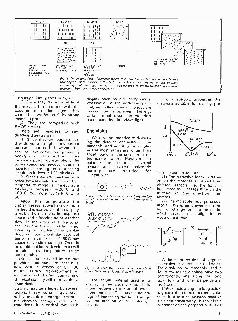
SOLID
ORIENTATIONANDPERIODICITY.CONSEQUENTLYPLANAR
ORIENTATION,PLANAR,NO PERIODICITY
NEMATIC
OR*
II
LIQUID
ORIENTATION RANDOMWITH NOPERIODICITYNOTPLANAR
11111 1 11111
1111111 1111
111111 1/7 I/ ///III II // /// //
/// ////// / /// //,////,
B
C
SUCESSIVE LAYERSOF THE TWISTEDNEMATIC
Fig. 4' The second form of nematic structure is 'twisted' each plane being rotated afew degrees with respect to the last; this is known as twisted nematic or morecommonly cholesteric (yes, basically the same type of chemicals that cause heartdisease!). This type is most important.
such as gallium, germanium, etc.(3) Since they do not emit light
themselves, but interfere with thepassage of incident light, theycannot be "washed out" by strongincident light.
(4) They are compatible withPMOS circuits.
There are, needless to say,disadvantages as well:
1 ) Since they are passive, i.e.they do not emit light, they cannotbe read in the dark, however, thiscan be overcome by providingbackground illumination. Thisincreases power consumption; thepower consumed however does nothave to pass through the addressingcircuit, as it does in LED displays.
2) Since they are operating in aphase between solid and liquid theirtemperature range is limited, at amaximum between -20 C and100 C, but more typically 0 C to60 C.
Below this temperature thedisplay freezes, above the maximumthe liquid is isotropic and no displayis visible. Furthermore.the responsetime near the freezing point is ratherslow, in the oroer of 0.2 -secondrise time and 0.6 -second fall time.Freezing or liquifying the displaydoes no permanent damage, buttemperatures in excess of 150 C maycause irreversible damage. There isno doubt that future development willbroaden this temperature rangeconsiderably.
3) The lifetime is still limited, butprovided conditions are ideal it isnow well in excess of 100,000hours. Future development ofmaterials with higher purity, andchemical stability will improve this agreat deal.Stability may be affected by severalfactors. Firstly, certain liquid crys-talline materials undergo irreversi-ble chemical changes under d.c.conditions, it is critical that such
display have no d.c. componentswhatsoever in the addressing cir-cuit, secondly chemical changes arecaused by impurities. Thirdly,certain liquid crystalline materialsare effected by ultra violet light.
ChemistryWe have no intention of discuss-
ing the detailed chemistry of thematerials used - it is quite complex- and most names are longer thanthose found in the small print ontoothpaste tubes. However, anoutline of the structure of a typicalnematic and a typical cholestericmaterial are included forcomparison
0 )- ".c" (2_>--\/\AAFig. 5. A 'Shills' Base. This has a fairly straightstructure about seven times as long as it isbroad.
TWISTED IN THIS DIRECTION.THIS IS A CONTRIBUTARYFACTOR TO THE TWISTEDNEMATIC STATE FOUND INSUCH COMPOUNDS.
CH3
00
CH3
Fig. 6. A cholesterol ester. The molecule isabout 8-10 times longer than it is broad.
The actual material used in adisplay is not usually pure, it ismore frequently a mixture of two ormore nematics. This has the advan-tage of increasing the liquid rangeby the creation of a "Eutectic"mixture.
The anisotropic properties thatmaterials suitable for display pur-
fTEMP
0% B100% A
ISOTROPICLIQUID
LIQUIDCR YSTALSTATE
LONGESTL.C. MIX
EUTECTICMIXTURE
0% A100% B
poses must include are:kl) The refractive index is differ-
ent as the material is viewed fromdifferent aspects, i.e. the light isbent more as it passes through thematerial in one direction thenanother.
12) The molecule must possess adipole. This is an uneven distribu-tion of change on the molecule,which causes it to align in anelectric field thus:
OV
Fig. 8.
ov 8
A large proportion of organicmolecules possess such dipoles.The dipole on the materials used inliquid crystalline displays have twocomponents, one along the longaxis (dl) and one perpendicular(teI) to it.
If the dipole along the long axis Ais greater than dipole perpendicularto it, it is said to possess positivedielectric anisotrophy. If the dipoleis greater on the perpendicular axis
ETI CANADA - JUNE 1977 41

FOC.- WriiTZ
it is said to possess negativedielectric anisotropy.
LONG AXISOF
MOLECULE
NEGATIVEDIELECTRICANISOTROPY
fLONG AXIS
OFMOLECULE
POSITIVEDIELECTRICANISTROPY
Fig. 9.
k3) The material also mustpossess anisotropic conductivity (asgraphite does). The conductivity innematic liquid crystals is greateralong the long axis than perpendi-cular to it.
(4) The material should have aresistivity of the order of 109 S2 Cm.
Display constructionThe displays work in two differentways, but the construction of thecells are similar, the differences are
A
GLASS PLATE
SPACER
CONDUCTIVELAYER
CROSS SECTION
CONDUCTIVELAYERS
EXPLODED VIEW
GLASSPLATE
GLASS PLATE
SEAL
GLASS PLATE
LIQUID CRYSTALLINEMATERIAL
Fig. 10.
mainly in the filters on the back andfaces of the display and of the typeof background.
The cell consists of a very thinlayer (about 12 ilm) of the liquidcrystalline material between twosheets of glass which have aconductive coating on their inside.One glass plate (a) has the actualseven -segment display etched on it.The other plate kb) has a commonelectrode etched on it. This con-ductive coating is either tin oxide, ora mixture of tin and indium oxidesThis provides an electrode withabout 90% transmission of light.
This conductive coat is furthertreated so that the molecules alignthemselves with the surface whilean electric field is not applied.
This provides a more or lesstranslucent display. When an elec-tric field is applied, the moleculesmove so as to align their dipoleswith the electric field. This causeschanges in the optical properties ofthe liquid crystal material whichappears as the display.
There are two principle tech-niques used here, dynamic scatter-ing and polarization modes.
Dynamic scattering:In this mode the liquid crystallinematerial is chosen such that it hasnegative dielectric anisotropy, withthe greater electrical conductivityalong its long axis. The moleculesare normally perpendicular to thesurface when an a.c. field isapplied the molecules, in clusters,move to re -align their dipoles withthe field. The re -alignment of thedipole is in opposition to theconductivity and the liquid becomes
CL
000001 10000A000000000 0000
VR 0 0 00 000000 00 0 00 0CLEA 0 0 0 000 0 0 0
NO FIELD
0 00 00 000'00 0 000 0 00 000400 0 000
AR 000000,000
000000001 0 0 0
Fig. 11.
MILKY
FIELD APPLIED
turbulent. This turbulence is seen asmilkiness in the display.
Since there is no light emittedthe display must be used to modifythe passage of incident light. Thismay be done either by passing lightthrough the display, or more usuallyby reflecting light from a mirrorbehind the display.
ILLUMINATION
TRANSMISSIVE MODE
Fig. 12.
REFLECTIVE MODE
'THE MIRROR IS OFTEN THE BACKELECTRODE
Fig. 13.
CLEAR
MILKY
CLEAR
The transmissive cell will appearto glow where the segments areswitched on. The reflective cell willappear misty where the segmentsare switched on. These displayshave the shortcoming of a ratherlow -contrast ratio.- That is, theapparent difference between theswitched on and switched offdisplay is not very great.
Polarization modesThe display is constructed in
basically the same way as thedynamic scattering cell. The diffe-rence lies in the type of liquidcrystalline material. The materialused is one which assumed a twistednematic structure, and has positivedielectric anisotrophy (the majorcomponent of its dipole along itslong axis).
In this case the inside faces ofthe cell are coated so that themolecules are parallel to them andaligned in a particular directionwhen no electric field is applied.
The cell thickness is designed sothat there is a complete 90° turn ofmolecules between the top and
42 ETI CANADA - JUNE 1977
iu I

bottom faces. The twisted nematic'has the property that it twists lightthat passes through it. Polaroidfilters are fitted above and below thecell so that light is polarized as itenters, and is twisted through 90°existing through a filter opposed at90° to the first. The light is thenreflected off a mirror and returns viathe same pathway.
FILTER
CELLWALL
WALLLL
FILTER
Fig 14
NON -POLARIZEDLIGHT
LONG AXIS OFMOLECULE
PLANE OFPOLARIZATION
PLANE OF POLARIZATION`
LONG AXIS OFMOLECULE
In this state the cell is clear.When an electric field is applied themolecules re -orientate to lie per-pendicular to the faces of the celland no longer twist the light. Thelight is now polarized as it enters thecell, and without being twisted,meets the second filter which is atright angles to the first and so doesnot pass the light. Hence thatportion of the display with the fieldapplied appears black ,since no lightis reflected).
If you have not seen this effectbefore take take two pairs ofpolaroid sun glasses, look at a
source of light with one in front ofthe other, thus:
Fig. 15.
Held in this way light, althoughpolarized, is free to pass through thesecond filter since the plane ofpolarization is the same for bothlenses. If one lens is now rotatedthrough 90° thus:
Fig. 16.
No light passes since the lightpolarized by the first lens will notpass through the second.
The effect of having the ''crossedpolaroids" in the cell causes almosttotal extinction of reflected light andconsequently a high contrast ratio,an almost completely black andwhite display. This is many timesbetter than the dynamic scatteringcells.
Addressing technique:The cells are normally operated
under a.c. conditions (although somecholesteric cells may operate underd.c.
The technique commonly used isto have d.c. pulses of identicalamplitude, one applied to the back,the other to the display segment viaan exclusive - or gate. In the offstate the two signals are on phase, inthe on state they are out of phase.
BACK
SEGMEN'
BACK
SEGMENT
DISPLAY ON
DISPLAY OFF
Fig 17
This technique has limitationsdue to the large number of bothcircuits and connections, howeverthis has been overcome by puttingthe circuit on the glass of thedisplay using thick film techniques!
Alternatives to this form of driveare to use multiplexed addressing,or m.o.s. shift register memory.
Other uses of liquid crystals:
The use of liquid crystal is notrestricted to electrical displays.Temperature measurement:
Certain nematic liquid crystalsicholesteric) change colour over thewhole range of the spectrum ,red toviolet) as their temperature-changes. Furthermore the colourchange is over a very narrowtemperature range, usually 2° or 3°C.The temperature at which thishappens and the range over whichthe change takes place can beadjusted by use of mixtures ofdifferent cholesterics.
A set of 10 or 1 2 of such cells ina row, the following one starting toshow colour at 2°C higher temper-ature than the previous one, forms auseful thermometer working over afairly restricted range. They have
Liquid crystal displays have made big in roadsinto the watch market but this may only be thebeginning of the story.
found application as living roomand refrigerator thermometers.
Perhaps a more important appli-cation is using liquid crystals whichhave a very narrow range overwhich they change colour (0.5°C).They have found application inmedicine since they can resolved:fferences of 0.05°C.
Assuming the liquid crystal is setto show colour at normal skintemperature any local deviationfrom the correct temperature willshow as a different colour. This hasapplications in detecting cancers,since they tend to be hotter thannormal body heat. They can also beused to see areas of poor bloodflow, or where allergic reactions aretaking place, since they are slightlyhotter or colder than the normalbody temperature.
Cells with extremely low temper-ature resolution can even detectfield intensity patterns ofmicrowaves and ultrasonic soundfields due to local heating effects.
As might be expected there arealso cells which change colour withapplied electric field. This wouldappear to have interesting prospectsfor the future.
Other interesting possibilitieswhich occur include the "memoryeffect". Certain cholesterics takehours, or some cases weeks, toreturn to their clear liquid crystallinestate after they have been scatteredby an applied electric field. Theclear state can be restored byapplying a different electric field.
Clearly liquid crystal technologyhas an enormous amount to offer awide variety of fields -- electronics,medicine and others. We are likelyto see further interesting develop-ments in the next few years as thistechnology takes over, andimproves on existing displaytechniques. How about an alphanumeric display with independentlyvariable colour segments?
ETI CANADA - JUNE 1977 43

hir nt
Fig. 1. Here a digital computer and an analogue computer are combined - the result is known as a hybrid computer.
IN THE LIGHT of growing interest inmicrocomputers and computingtechniques in general many readersrequire some basic grounding indigital computers. What follows isnecessarily an introduction only -computers are now extremelysophisticated in design and themanufacturing methods very spec-ialised. It is, however, quite importantthat the operation of computers beunderstood by electronic craftsmenat a general systems level. Thisgeneral article will introduce thephilosophies, the hardware and theoperation of digital computers from atechnical rather than user -onlyviewpoint. (Analogue computers arestill valuable in some applications butin general, machine computing isnow mainly done digitally).
WHAT IS A COMPUTER?Regardless of whether a computer is
digital or analogue in operation its roleis to perform various kinds ofmathematical operations. Theanalogue machine cannot performlogic operations. (unless joined witha digital computer, in which case it is
known as a hybrid computer - asshown in Fig. 1) its use is generallyrestricted to what are called linearmathematical problems in whichsignals vary continuously andinformation is transferred as levels notas digital codes. Analogue computerscan be very good at such operations,often better than a digital computer ofsimilar cost. The digital machine, onthe other hand, (a general purposeinstallation is shown in Fig. 2) can
perform almost any kind ofmathematical manipulation, howeverspecial techniques are often needed tosolve analogue problems. Analoguetype signals must be sampled and eachsample converted into a digitalequivalent before they can beprocessed in digital machines: this iswhere the digital machine in certainapplications may be less efficient thanthe analogue alternative.
As well as performing arithmeticaloperations (called scientificcomputing) the digital machine can beinstructed to process or sort discretedata in digitally encoded form (calleddata processing or DP, for short).Typical computer data processingoperations are the sorting of numerical
data - for example to see how manypeople have heights of various chosenvalues, or the booking of airline seats.Mixed working, where scientificcalculation and data-processing areboth involved, occurs for example, incosting out a building estimate, raisinga stock value for a business, orproducing pay -slips.
Digital computers may also calculatetables by automatically incrementingthe input data between preset limits.For example the computer could beasked to generate and print the skiesof all angles between 10° and 90° at1° intervals.We pause now to note that we call
such machines computers notcalculators. The term calculator has
F;g. 2. General purpose digital computer, this centre is used by Lloyds Bank.
44 ETI CANADA - JUNE 1977

traditionally been used to describemachines which perform a fixed set ofmathematical calculations. The termcomputer on the other hand, isreserved for those machines whichmay be reconfigured by a set ofprogramme instructions to performany particular task. However suchdistinction between the roles ofcalculator and computer is becomingincreasingly difficult to make. Somecomputers are now dedicated toperforming calculator like tasks andsome calculators are now so flexiblethat they can be programmed toperform a variety of tasks.
Fig. 3. As yet, computers can onlydo what they are programmed to do.
In the 1950s, when powerfulelectronic computers were emerging,the popular concept was of a machinethat would soon have thinking powersof its own - and its own will andimagination - as depicted in Fig. 3.Although we must concede such is
probably possible one day - no onehas yet gained an inkling into how thisextra facility could be realised.Computers are merely machine slavesthat, if working internally as thedesigner thinks and intends, willperform as commanded. The operatorinforms the machine of its job via theprogramme presented to it. Where thecomputer has valuable merit is in itsability to perform calculations andprocess numerical data at rates vastlygreater than a human mind, withrarely an error, and for hours on end ifneed be. It is a tool and no more. Tosay the computer accidently sent the$1,000,000 bill to Bill Blogs is entirelyincorrect. The programmer or themachine did not perform as hopedthrough one or the other beingdefective in the instructions given orthe way they were obeyed.
As well as computers that operate
INP
INPUT X
T V
L _ -<-SET POINT
I DETERMINATION
Fig.4. Process controlcomputers areelectronic dataprocessing machines,dedicated to aspecific task.
PROCESSOUTPUT 2
CONTROLLERS
LOGICSTORAGEANDCOMPARISON
HCHECKING1--- -H TIMER
PROCESS COMPUTER
SENSING (t)DEVICE
<-
only when the operator givesinstructions there is also the dedicatedmachine that, once set internally tocompute or process in a predeterminedway, becomes part of a process. Ithelps control by working at the samerate as signals are generated in theprocess - real time working.Process -control computers, as these arecalled, operate on data and performcalculations as part of many feedbackloops in, say, a chemical plant. Figure4 shows this use in a diagrammaticform. Other names variously used todescribe this use are in -line, on-line,direct -digital -control (DDC) or justplain computer control. Whereverautomation of extensive complexprocess is necessary a computer willusually be found - waste -water
treatment plants, paper manufacture,natural gas and electricity distributionietworks, satellite control andpower -station plant operation are buta few of thousands of in -lineapplications. Computers are far moreuseful in this task than humanoperators - see Fig. 5.
On-line operation (although notgenerally agreed upon) is a termprobably best reserved for cases whereeach of many input terminalsconnected to a central computer cangain access to the unit when itbecomes available. This is also knownas time-sharing and is used where thesignal processing rate need not matchthe process. computers used inbanking often operate in atime-sharing mode - bank branches
SpeedPower
Consistency
Complex activitiesMemory
ReasoningComputation
Input sensitivity
MachineMuch superiorConsistent at any level
Ideal for routine, repetition,precisionMulti -channelBest for literal reproductionand short-term storage
Good deductiveFast, accurate - poor at errorcorrectionSome outsice human senses,e.g. radioactivity
Insensitive to extraneous
Poor for pattern detection
Overload reliability Sudden breakdownIntelligence None
Manipulativeabilities
Specific
Man
Lag 1 sec.
1500W for about 10 sec, 350 Wfor a few minutes, 150 W forcontinuous work over a day.Not reliable - should bemonitored by machine.Single channel.Large store multiple access.Better for principles andstrategies.Good inductive.Slow, subject to errorGood at error correction.Wide range (1012) and varietyof stimuli dealt with by oneunit, e.g. eye deals withrelative location, movementand colour.Affected by heat, cold, noiseand vibration.Good at pattern detection.Can detect signals in highnoise levels.Graceful degradation.Can deal with unpredicted andunpredictable.Can anticipate.Great versatility.
Fig. 5. Fitt's list summarizes the relative advantages of man versus machine control.
ETI CANADA - JUNE 1977 45

can gain access to the central accountrecords - a short wait may be necess-ary. When the computer works ondiverse problems at the will of theoperator and is not used for any dedic-ated purpose it is said to be off-line.Originally electronic computers were
1 Fig. 6.'Mini-computers come in all shapesL. and sizes. On the left, in the console, is the
H.P. 2000 that controls the pattern being71 knitted on the Kirkland knitting machine.
huge - several rooms filled with racksof valve electronic circuits. In themid -sixties manufacturing techniquesand designs were such thal: a new styleof less versatile but compact computerwas marketed - the so-calledminicomputer. Figure 6 shows but one
kind of mini -computer systememployed to control a process byproviding instructions as needed. (It isnot used in closed -loop as this processdoes not feed data back to thecomputer).
We do not use the word "generation"
Fig. 7. Compact electroniccomputer systems becomereality when valves werereplaced by solid-statecomponents. This singleplug-in unit, from aPegasus computer of the50s, would today haveits entire function madeon a pinhead in LSItechnology.
46 ETI CANADA - JUNE 1977

in connection with the minicomputerbecause that term is used in computerjargon in two distinct ways. It maydescribe the hardware used - firstgeneration computers use thermionicvalves and ordinary cable wiring, suchas shown in Fig. 7, second generationmachines use discrete transistorcircuits on printed -circuit boards, thirdgeneration machines useintegrated -circuitry and the mostrecent fourth generation computersuse large -scale -integration LSImanufacturing methods - A fifthgeneration computer is yet to emergeas an accepted concept. The otheruse of "generation" is in describingthe system interconnections - thephilosophy of system hardwareinterconnection and style, andcapacity of the store involved.
A HISTORY OF COMPUTINGMACHINES
Intertwined with the development ofmachine operated logic was the gradualincrease in sophistication ofcomputing machine systems.
Earliest devices were simplecalculators based on mechanicalconcepts. They performed simpleaddition, subtraction and sometimesmultiplication and division, doing thiswithout the ability to store or holdvalues other than inputs and computedoutput.
Space does not permit extensivedescription of this history - see thereading list for that. Figure 8 showsthe style of the first calculatingmachine of the "modern" kind. Thisperformed arithmetic addition andsubtraction only, by mechanicallymanipulating interconnected countingwheels and was probably made byPascal in 1642. In 1671 Leibnizmodified the same mechanism (seeFig. 8) to obtain multiplier action,producing his own design calculatormuch later - in 1694. Becausemechanism manufacture at that timewas crude indeed - all parts wereindividually hand-crafted - theLeibniz machine was not reliable eventhough the concepts involved weresound. Improvements in mechanicalmanufacture had to occur before aroutinely useful gear and crankcalculator could be built (by deColmar in 1820). Thus, through theseand many other gradual improvementsto method and manufacture, the scenewas set for grander ideas.A major advance was made by
Babbage. Charles Babbage was born inDevon, England. In 1792, he became aProfessor of Mathematics atCambridge University and had a
consuming passion for mechanicalmachines that could perform far more
PASCALL STRIPPEDAR CARRY
; Aliel-10meg-4
El., 51,1,71WHEEL CARRY40;
OA,
Fig. 8. Pascal's calculator of 1642 usedstripped gear toothed -wheels to producea carry to the next decade.- The Leibnizmachine made use of the stepped wheel.
advanced mathematical onorationsthan any previous apparatus. His firstmachine, shown in Fig. 9, wasdevised to solve differential equationsby calculating differences. This was his"Difference Engine" of about 1812. In1833 he conceived a second, quitedifferent general-purpose engine - theso-called "Great Calculating Engine".In pri n cf)le, it could do any
mathematical operation by followinginstructions programmed into it by theoperators. It could also makedecisions, on what to do next, thatwere based on its just calculatedresults.
Babbage used punched -cards forinput information (a reasonably logicalchoice in view of the many repetitiveindustrial processes using this controlmedium at that time), a memory(which he called "the store"), a
number processing section (called themill), a means of transferring results toand from the store, and automaticoutput (as cast type ready to print). Itwas E grand machine having ability tostore 1000 fifty -digit numbers in itsstore. It even had overflow indication.
The intended power supply wassteam. Sadly, Babbage's engines werenot proven in practice in his time;those built were either not completedor proved too unreliable. Manufacturingmethods were still incapable ofmaintaining the tolerances needed - itwas a classical example of a conceptwaiting for the requisite technology.
Complicated mathematical equationsolving in the 19th and very early 20thcentury was performed on other kinds
:1:1111111111 11111101111Itt
rapt t.i1111111111111111
.4111.;i tiib, .II
millicqu_
3'1111111111 MEM
to1117771:ThiIi
Fig. 9, Babbage's differenceengine of circa 1812.
(753, j
11.1.-NE
11111.111111111, IIli1.
nfiniiin
li ilk .....,lw.17111:1111414?liiiiii. - nbuintr mvui _..... .J.J1E-1 ' `ort.F.mi.. I, ,mili
. italiwib PBE
tvr AMMIII"' I nor IIone. I III44 onindifillip iii 4;4-.1113 L,.,=-.. ,r.1 brit I flinnriummutur
" V=IITEL- I OM,I , -_-_-
" 4441111.1 °In 1,.-.WM AWN iCaila-, -II : in llllll r4- -Niirrenh . i ivNts, 11
- -r-c t, pli I no mLa" meirrnin 1 ="411 .4.
41"2'ilaMi a. li II12no_ 4.mons_17m.li Ir.. .14:,;-...., ..-%=..., r."........,67:2; J111,4
I_ -,....o.i . - .1I'V
J: al
1 : .. llllll .__.. ...11..., ,T1 OR I ' t. .1 B...),...... ,. .i.,i...
r70- munsorrei
moonrw 7 ,.-nonoomon,w,
ilrip., 7161.0 1 , ..111111=11111!,;, Al {I" 1 0.....itt ill ofin .1 .11:01LIWiN4i,111-102 NU
il I 1 tin!rnoloomT.ol '1....16rmarlti, .,i..... ,,,, ,,.: .. .r., -....., ..,--.. 9 0 12 ..,.._,.,
walogimgar ,._ ... 177I
illemr-4, Tin. la , iii inimatiiiip.4! le -"1"- JUN0 L., ..1 4 , ...,..,.. .- s4,21 ±i pa, .11 Ilni"iti
11.1" ii lam 1Ili inumniiiii.. 'ill l._,.... .3172 liB6..alzi, i,,
roe 1 9 0 1 .rii,- inWimp . it' I ''. '."=-- ' ,.-.
I. - - - ,r ..,-... ..,,,,,.1,i
F..,mldiewWil
i..41 i_I.
.
1:.-11._i,ii1. I..,%.,".,'135'11'
I 02"1g-
!II 161111.11.16111,11 Ilk,i1M111/* ;,' f 11 '
jil il'EMII. n inmonrinurA-.
ny4a . .1 11..... 1.71E. 0.=7I - . .11 ..11.a
...11 H. 113351 del.
16111111111111w-
ETI CANADA - JUNE 1977 47

INFORMATION
COMPONENT NOTATIONS AND UNITSWe normally specify components using the recentlyagreed International Standard. Many readers will be un-familiar with this but it's simple, less likely to lead to errorand will be used by everyone sooner or later. ETI hasopted for sooner!
Firstly decimal points are dropped and substituted withthe multiplier, thus 4.7uF is written 4u7. Capacitors alsouse the multiplier nano (one nanofarad is 1000pF). Thus0.1uF is 100n, 5600pF is 5n6. Other examples are 5.6pF= 5p6, 0.5pF = Op5.
Resistors are treated similarly: 1.8M ohms is 1M8,56k ohms is 56k, 4.7k ohms is 4k7, 100 ohms is 100R,5.6 ohms is 5R6.
BACK NUMBERSPrevious issues of ETI-Canada are available direct fromour office for $2.00 each. Please specify issue by themonth, not by the features you require.
EDITORIAL QUERIESWritten queries can only be answered when accompaniedby a self-addressed, stamped envelope, and the reply cantake up to three weeks. These must relate to recentarticles and not involve ETI staff in any research. Markyour letter ETI Query.
NON-FUNCTIONING PROJECTSWe cannot solve the problems faced by individual readersbuilding our projects unless they are concerning inter-pretation of our articles. When we know of any error weshall print a correction as soon as possible at the end ofNews Digest. Any useful addenda to a project will besimilarly dealt with. We cannot advise readers on modifi-cations to our projects.
COMPONENT STORESETI is available for resale by component stores. We canoffer a good discount and quite a big bonus, the chancesare customers buying the magazine will come back to youto buy their components.
PRICESAll prices quoted in the editorial of ETI are in Canadiandollars, except where stated. Advertisers in U.S. may giveU.S. dollar prices. Where we only know an overseas price,e.g. in U.K. pounds, we convert approximately to Cana-dian dollars, erring on the conservative side, where possi-ble.
COMPONENT SUPPLY
We do not supply components for our projects and areunable to supply advanced information on componentsused in any projects. However to enable readers to obtainprinted circuit boards without undue delay we will besupplying retailers and manufacturers with certain p.c.board designs. Any company interested in receiving suchdesigns should write to us on their headed note paperrequesting details.
PHILIPS
The PhillipsCassette Triothe high quality result of 12 years inCompact Cassette researchIn 1963 Philips invented the CompactCassette System and so started arevolution in recording.Now, continuing progress has made itnecessary for us to produce a larger, moresophisticated range of cassettes.In Philips Cassette Trio, you will find ahigh quality cassette for every purpose.
The Philips tape is so strong, that it cannotsnap, tear or stretch easily.The Philips magnetic coating ensuresconstant high recording quality.The magnetic coating is specially polishedto prevent wear on the magnetic heads, toreduce friction between tape and tapeguides, and to ensure the closest possiblehead contact for better reproduction.
Quality CassettesIn 1963 we inventedthe compact cassettesystem.Today - in 1977 wehave a range of highquality cassettes tosuit every purpose.For more informationCall your nearestPhilips ConsumerService Branchlocation.
*Floating foil security toprevent tape jammingA unique invention (patent pending).Two pieces of transparent foil in aspecial, corrugated shape guide the tapein the cassette and prevent it fromjamming.
Service Branches from coast to coast: Halifax: 902-429-0260 - Quebec City: 418-681-4639 - Montreal: 514-342-2043 - Ottawa: 613-829-9295 - Toronto, West: 416-781-5201 - Toronto, Central: 416-489-2022 - Toronto, East:416-438-9822 - Hamilton: 416-547-4914 - London: 519-686-9671- Sudbury:705-560-4866- Winnipeg: 204-774-1931 - Regina: 306-543-0446 - Saskatoon: 306-244-2299 - Calgary: 403-243-7737 - Edmonton: 403-452-8491 -Vancouver: 604-434-6647.
48 ETI CANADA - JUNE 1977

Fig. 10. This relay -switched digital calculator was built by Zuse in Germany in 1936.(This photograph has been included because of its historical interest - unfortunately
the original print is of border -line quality).
of special purpose mechanicalcalculating devices. The planimeter,which determines area under a curve,was devised in 1814, the mechanicalball -and -disk integrator was deviced in1876 (by Lord Kelvin's brother). Withthese and other basicmechanical -function solving ideas,Lord Kelvin and others put systemstogether that carried out specialisedcalculations. Kelvin produced a tidalamplitude and phase predictor forsea -tide forecasting around 1874.Later in 1898 Michelson (of speed oflight fame) worked with Stratton toproduce a mechanical harmonicanalyser.Special-purpose mechanical
calculators were still in use in the1940s. During World War II, forinstance, gun crews fed dataconcerning range, direction and windstrength into computers by which thecorrect aiming information for the gunwas computed.
Today a few equipments stillperform simple operations bymechanical means for in applicationswhere electrical power is not availableand the inputs not in electrical form itmay be more economic to usemechanical methods.With the advent of electronic
amplification at the turn of thiscentury electronic circuitry graduallyreplaced mechanical mathematicalfunctions. This was feasible because ofthe superior speed of calculation,reduced manufacturing tolerances andgreater reliability of electronics. Theswing to electronics was intensified bythe need to process an ever increasingamount of data that arises in, forexample, more complex equationsolving, census taking, or warfare.
Hollerith devised the punched -cardsorting machine to help handle theU.S. census data. This device won an1890 competition organised by theU.S. Government.
Electric computers using the samebasic system that we use today becamereality around 1936 when Zuse, inGermany, built the relay -switcheddigital calculator (shown in Fig. 10).This machine featured automaticcomputing, binary arithmetic, floatingdecimal point and punched -tapeprogramming. In 1937 the USA's IBMCorporation began development of amachine called the AutomaticSequence -Controlled Calculator, or,locally, just Mark I.
The trend toward total electronicworking continued. ENIAC, generallyrecognised as the first all -electroniccomputer, had 18 000 valves and couldoperate at 500 additions per second.This was followed, after many otherdevelopments, by the first p-oductioncomputer - the Remington RandUNIVAC I. It has been estimated thatall computers installed in the U.S. in1955 could do just 250 000 additionsper second. Just one low -cos: mini cando that today.
In 1959 a U.S. refinery installed thefirst process -control computer systemand in 1960 a large steel corporationin U.S. was the first to use a computerto carry out inventories, handle ordersand control production. Airlinebooking by computer began in 1964.
Integrated circuits (in the thirdgeneration machines) came into use in1964 via the IBM 360 system and by1970, in the U.S. alone, roughly1 000 000 people were employedin making and using digital computers.
Single chip, fourth generation
machines came to reality around 1972with the use of LSI. Today pocketscientific calculators containing over30,000 transistors in LSI form can bepurchased for about $40. In 1974 theworld market for small calculatorswas estimated to be 40 million! Thecost of modern computers is nowgoverned by the cost of theperipheral bits and pieces rather thanthe processing unit itself - the costof the electronic components is nowjust a minor part of the whole.
Further reading
"A Computer Perspective", C. and R.Eames, Harvard University Press,Massachusetts, 1973. (This is a
definitive work on the developmentof data processing equipment from1800 to 1940).
"Electronic Computers MadeSimple", H. Jacobowitz and L.Basford, W.H. Allen, London, 1967.(Although out of date with respectto certain aspects of hardware thisprovides a valuable basis for technicalunderstanding of both analogue anddigital computers. It also explains thearitimetrical operations).
"Introducing Computers", M. Laver,HMSO, London, 1973. (A versioncompiled for users with a littletechnical knowledge. It discussesprogramming procedures).
"Computers at work" J.O.E. Clark,Bantam Books, London 1973 (Amost useful book on wherecomputers are used).
"Electronic Computers", S.H.Hollingdale and G.C. Tootil, PenguinBook A524, Harmondsworth, 1965.(A fine layman's summary ofanalogue and digital computersincluding a lengthy chapter on whatsort of jobs computers do).
Computer programming is .overedin many texts and booklets. Oneexample is:"Elements of Computer
Programming", K.P. Swallow andW.T. Price; Holt, Rinehart andWilson. New York, 1965.
ALGOL language began to emerge in1958 as a step toward a universalcomputer language for scientificworking. COBOL is the commercialcounterpart. Relevant books are:
"Basic ALGOL", W.R. Broderick andJ.P. Barker, IPC Electrical andElectronic Press, 1970.
"A Guide to COBOL Programming",D. McCracken, Wiley, New York,1970.
ETI CANADA - JUNE 1977 49

PUBLICATINrFROM EllinFROM THE PUBLISHERS OF
ELECTRONICS TODAY INTERNATIONAL
ETI
CIRCUITS
Not
$5.00 £1.50 $2.50
from the publishers ot fttronics today International
Take the mysteryout of electronics withthis straightforwardlogical course
CIRCUITS No. 1:A brand new concept from the house of ETImore than 100 pages packed with a widerange of experimenters circuits. Based onthe 'Tech Tips' section carried in the over-seas editions of ETI, Circuits 1 is the first ofa series of specials - produced for the enthu-siasts who know what they want, but notwhere to get it! Circuits 1 will also act as acatalyst for further development of ideas,ideal for the experimenter. The collection ofmore than 200 circuits is complemented bya comprehensive index, making searches fora particular circuit quick qnd simple. Also,similar circuits can be compared easily, dueto the logical layout and grouping usedthroughout. Last and by no means least, Cir-cuits 1 has no distracting advertisements inthe main section!
TOP PROJECTS No. 4:A collection of 28 constructional projectsreprinted from ETI. This is the fourth in aseries published by the British edition (Nos.1,2, and 3 are not available). Projects arecomplete and include: Sweet Sixteen StereoAmp, Waa-Waa, Audio Level Meter, Expand-er/Compressor, Car Anti -Theft Alarm, Head-light Reminder, Dual -Tracking Power Sup-ply, Audio Millivoltmeter, ThermocoupleMeter, Intruder Alarm, Touch Switch, Push -Button Dimmer, Exposure Meter, PhotoTimer, Electronic Dice, High Power Beacon,Temperature Controller, Electronic One -Armed Bandit plus many more.
$5.00 FOR CIRCUITS No. 1$2.50 FOR TOP PROJECTS No. 4
ELECTRONICS - IT'S EASY:Volumes 1 and two of the best introductoryseries to electronics ever published in a mag-azine. Volume three, completing the series,will be available in a few months.
Electronics - It's Easy! takes a fresh lookat electronics: it avoids the usual introduc-tions to the subject which mostly seem des-igned to frighten you away before you reachpage 10!
Volume one leads the raw beginner froma gentle introduction, explaining circuits in'black -box' form up to the use of operation-al amplifiers.
Volume two deals with more advancedtechniques, and deals with digital and logiccircuits.
These books have sold extremely well inAustralia and in Britain. In Holland theyform the basis for a correspondence course.
$6.00 FOR BOTH,$3.50 INDIVIDUALLY
THESE PUBLICATIONS ARE AT PRESENT ONLY AVAILABLE FROM ETI
Send your orders, with payment (not cash), toETI PUBLICATIONS
Electronics Today InternationalUnit Six
25 Overlea BoulevardToronto, Ontario
M4H 1B1Please specify which publications you require, and print your name and address clearly.
WAA WAA. SIMPLE CMOS TESMEPll Fl AMP 8W t 8W. CAR ALARMDICE. AUDIO MILLIVOLTPUSH BUTTON
RACKING P.S.U.UDER ALARM. PHOTO TIMER
CAR AMP. EMERGENCY BEACONONE ARM BANDIT, LOGIC PROBECOURTESY LIGHT EXTENDERHEADLIGHT REMINDER. TOUCI-SWITCH. FLASH TRIGGER. BASICPOWER SUPPLY. CAR FLASHEREXPOSURE METER. TEMPERATURECONTROLLERS, THERMOCOUPLEMETER. CERAMIC CARTRIDGEPREAMP
electronicsvloliata 2 WS easyfrom the Wolters ot electratics today international
£1.20
Power SuppliesWaveformsFiltersDigital SystemsLogic
50 ETI CANADA - JUNE 1977

ETI DATA SHEETMC14490 HEX BOUNCE ELIMINATOR MOTOROLA
The MC14490 is constructed withcomplementary MOS enhancement modedevices, and is used for the elimination ofextraneous level changes that result wheninterfacing with mechanical contacts. Thedigital contact bounce eliminator circuit takesan input signal from a bouncing contact andgenerates a clean digital signal four clockperiods after the input has stabilized. Thebounce eliminator circuit will remove bounceon both the "make" and the "break" of acontact closure. The clock for operation ofthe MC14490 is derived from an internalR -C oscillator which requires only an externalcapacitor to adjust for the desired operatingfrequency (bounce delay). The clock may alsobe driven from an external clock source or theoscillator of another MC14490.
CHARACTERISTICSThe single most important characteristic
of the MC14490 is that it works with a singlesignal lead as an input, making it directlycompatible with mechanical contacts.
The circuit has a built in pullup resistor oneach input. The worst case value of thepullup resistor is used to calculate the contactwetting current. If more contact current isrequired, an external resistor may beconnected between V and the input.
Because of the built in pullup resistors, theinputs cannot be driven with a singlestandard CMOS gate when VDD is below 5V.At this voltage, the input should be drivenwith paralleled standard gates or by theMC14049 or MC14050 buffers.
The clock input circuit (pin 7) has Schmitttrigger shaping such that proper clocking willoccur even with very slow clock edges,eliminating any need for clock preshaping. Inaddition, other MC14490 oscillator inputscan be driven from a single oscillator outputbuffered by an MC14050.
The MC14490 is TTL compatible on boththe inputs and the outputs. When V is at4.5V, the buffered outputs can sink 1-.6 mAat 0.4V. The inputs can be driven with TTL asa result of the internal input pullup resistors.
OPERATIONTo understand the operation, we
assume all bits of the shift register are loadedwith l's and the output is at a 1 or high level.
At clock edge 1 the input has gone lowand a 0 (low level) has been loaded into the,first bit or storage location of the shiftregister. Just after the positive edge of clock1 in input signal has bounced back to a logic1. This causes the shift register to be reset toall 1's in all four bits - thus starting thetiming sequence over again.
During clock edges 3 to 6 the input signalhas stayed low. Thus a logic 0 has beenshifted into all four shift register bits and, asshown, the output goes to a 0 during thepositive edge of clock pulse 6.
It should be noted that there is a 31/2 to4Y2 clock period delay between the cleaninput signal and output signal. In thisexample there is a delay of 3.8 clock periodsfrom the beginning of the clean input signal.
After some time period of N clock periods,the contact is opened and at N + 7, a 1 isloaded into the first bit. Just after N+7,when the input bounces low, all bits are resetto 0. At N +8 nothing happens because the
ETI CANADA - JUNE 1977
BLOCK DIAGRAM
Ain
.v1 0
VD0 Pin 16
Data
4-13i1 Static Shift Register
Shift LoadDNay
t01 02
Osc in 7 0-le Oscillatorand
01 01 02 Vss Pin 8
TwePhase°.out 9 0-0 Clock Generator -le 02
011 02
Bin 140 Identical to Above Stage Bout0 2014 024
Cin 3 0 Identical to Above Stage coot0 13
0t02
Din Identical to Above Stage 4 Dout120 O
04 02
E in 50 Identleel to Above Steps Eir,,0110.14 024
Fin 10 0 Identical to Above Steil* Fout0 6
Clock
Input
Output
ContactOpen
3 4 5 6 7 N+8 N+9 N+10 N+11 N+12 N+13
_,411111.11.1
Contact Closed
ContactBouncing
input and output are low and all bits of theshift register are 0. At time N + 9 andthereafter the input signal is a high (1) cleansignal. At N+ 1 3 the output goes high (1) asa result of four 1's being shifted into theshiftregister.
Assuming the input signal is long enoughto be clocked through the Bounce Eliminator,the output signal will be no longer or shorterthan the clean input signal plus or minus oneclock period.
CLOCKINGThe only requirement on the clock
frequency in order to obtain a bounce freeoutput signal is that four clock periods do notoccur while the input signal is in a false state.
If the user has an available clock signal ofthe proper frequency, it may be used byconnecting it to the oscillator input (pin 7).However, if an external clock is not availablethe user can place a small capacitor acrossthe oscillator input and output pins in orderto start up an internal clock source. The clocksignal at the oscillator output pin may thenbe used to clock other MC14490 BounceEliminator packages. With the use of theMC14490, a large number of signals can becleaned up, with the requirement of only onesmall capacitor external to the Hex BounceEliminator packages.
aContact
Bouncing
Contact Open0 -
ASYMMETRICAL TIMINGIn applications where different leading
and trailing edge delays are required (such asa fast attack /slow release timer.) Clocks ofdifferent frequencies can be gated into theMC14490. In order to produce a slowattack/fast release circuit leads A and Bshould be interchanged. The clock out leadcan then be used to feed clock signals to theother MC14490 packages where theasymmetriclal input/output timing isrequired.
otcout
51

MC14490 CONTINUED MOTOROLA
LATCHED OUTPUTThe contents of the Bounce Eliminator can
be latched by using several extra gates. If thelatch lead is high the clock will be stoppedwhen the output goes low. This will hold theoutput low even though the input hasreturned to the high state. Any time the clockis stopped the outputs will be representativeof the input signal four clock periods earlier.
Cloy
Latch - 1Unlatch - 0
0 c
MULTIPLE TIMING SIGNALSBounce Eliminator circuits can be
connected in series. In this configurationeach output is delayed by four clock periodsrelative to its respective input. Thisconfiguration may be used to generatemultiple timing signals such as a delay line,for programming other timing operations.
One application of the above is where it isrequired to have a single pulse output for asingle operation (make) of the push button orrelay contact. This only requires the seriesconnection of two Bounce Eliminator circuits,one inverter, and one NOR gate in order togenerate the signal AB. The signal AB is fourclock periods in length. If the inputs to theNOR gate are interchanged the pulse AB willbe generated upon release or break of thecontact. With the use of a few additionalparts many different pulses and waveshapesmay be generated.
1---°>( °
In0
A
BE 1Out
D 0
In0 C BE 2
A a Active LowB = Active Low
Oct0 0
B
Ae
A,B.E 1
15
A out
14
BoutB E. 20 aBin
3
o13
B.E. 3a 0 coot
12 4B.E. 4o a 134.,
Din
5 11
B.E. 5o aEin
E t
10 6B.E. 60 0 0 0 F.
Osc Osc0,1
THREE TERMINAL VOLTAGE REGULATORS NATIONALVoltage regulator use can be expandedbeyond that of the simple three -terminalfixed voltage regulator. Some of the circuitswhich are practical and useful are describedin this section. Pertinent equations areincluded rather than providing fixed com-ponent values as the circuits are equallyapplicable to all regulators within a family.
POSITIVE REGULATORS
VIN VOUT
REGULATOR
Cm 4.-TCOOT-
MEE TEXTI (SEE TEXTI
FIGURE 1 Basic Regulator Connection
If the regulator is located more than twoinches from the supply filter capacitor, asupply bypass capacitor is required tomaintain stability (much as is the case withop -amps). This should be a 0.22 .1F orlarger disc ceramic, 2µF or larger solidtantalum, or 25 p.F or larger aluminiumelectrolytic capacitor. Transient response ofall the regulators is improved when outputcapacitors are added. To minimize highfrequency noise, an 0.1 p.F output capacitoris recommended on the LM78LXX andLM 3 0 9 series.
HIGH CURRENT REGULATOR
This current circuit takes advantage of theinternal current limiting characteristics of theregulator to provide short-circuit currentprotection for the booster as well. Theregulator and Q, share load current in theratio set between R2 and R, if VD=V,,,,,,.
SINGLEPOINT CND
FIGURE 2 High Current Regulator withShort Circuit Limit During Output Shorts.
R211 - R1 'REG
During output shorts
I AR21 IREGisci
If the regulator and Q1 have the samethermal resistance 03c and the pass transistorheat sink has R2/ R, times the capacity of theregulator heat sink, the thermal protection(shutdown) of the regulator will also beextended to Q,.
ADJUSTABLE OUTPUT VOLTAGE
FIGURE 3 AdjustableA fraction of the regulator current V,,/ R, isused to raise the ground pin of the regulator.and provide through voltage drop across R2,an adjustable output voltage.
RVG) VREG + R7110 +V R1EG 1
=30VVIN
-VIN
CIN0.22 fT1
'Solid Tantolum.
R4
-.7 R5
FIGURE 4 Variable Output Voltage of 0.5- 28V
A wide range of output voltages can beobtained with the circuit of Figure 4. A 0.5 -to 20 -volt supply can be built using a 30 -voltsupply and a conventional op -amp, such asthe LM143. If
R2 + R3 R4 + R5 = R, and R2/R3 = 1/10,
then Vo 1VREG----/ y REG,R ,
R4 11111 iFI4R44R
Since V, is inversely proportional to R4, lowoutput voltages can be very accurately set.The required R, is
VIN' io
The Vow, is dependent on VIN and Vdpoprovided that the amplifier can source thecurrent required to raise VG to V, VREG.
Example:- -15 V RI -2K2
V+IN = 430 V R2 -910RVo 0.5-28V R3 = 9K1
LM340K-05 R4 + R5 = 10K
No
COUP2.20O
52 ETI CANADA - JUNE 1977

ELECTRONIC SHUTDOWN
yIN
Cr -A-O 22
I I ONI IIOCItV0
03
Required if regulator far from power supply filter
FIGURE 5 Electronic Shutdown Circuit
Electronic shutdown in three -terminalregulators is done by simply opening theinput circuit using a transistor switch. Q,operates as the switch which is driven by 02.The control voltage Vc can be TTL compatiblewith the use of R3 = 1K. R, is a biasingresistor, and R2 can be calculated as
VIN -.1 V"2
10PSATIO1)
Figure 6 illustrates a short -circuit -dependentpower shutdown circuit with reduced heatsink requirements under short-circuit condi-tions.
When the power is first applied, (12 turnsON and saturates Q,. The regulator outputramps up to turn 03 ON, which turns Q2 OFF(Vc should be > VA), thus maintaining Q, inthe ON state.
FIGURE 6 Output Electronic Shutdownon High Voltage Regulator
When the output is shorted, 03 turns OFF, Q4turns ON to clamp a2 OFF. Q1 loses basedrive and so opens to isolate the regulatorfrom VIN. When the short circuit is removed,Q, loses some base drive and enables Q2 tore -start the regulator. Q, always operates as aswitch and needs no heat sinking. a2 and Qneed not be matched. a4 may be any smallsignal PNP transistor. The entire circuit (lessregulator) fits easily on a one -inch squre PCboard.
Example: LM340K-24VIN= 36VVo= 24V10=1AVA= 2.5VVA= 8VVc= 4.8VQ,= TIP 32Q2=2N4141Q3=2N4141(24= 2N2906
R 1=500RR2= 250R, 2WR3=3K3R4= 240RR5=62R136= 2K192= 1KR9= 680RR9=3K3
NEGATIVE REGULATORS
All the applications circuits for positiveregulators can be ilsed with the polaritiesinversed for the negative regulatorLM320 / 345 series (e.g., reverse the senseof the diodes, replace PNP's with NPN's etc.,etc.),
CI7.1
INPUT
VIM
O..721 1,4avesoarveni 0.10.1110
IMmAaa
SELECT 02 AS 101.1.0142
OUTPUT "'"Z"1.41121 117 - TOPL14171112 - /SPMIN IS - I II
Venable Output
(d) High Current Regulator
2N3055 (for 5 AIor TIP31 (for less than 2-3 A
FIGURE 7 Negative Regulator Circuits
BASIC DUAL POWER SUPPLY
VIIuT*.ISV AT 1 A/AP
Veu,--ISV AT I AMP
SMAI LeAtolum
Num CI and CO ..... .1 espolalors ace lacaiml I., If HI powe. utoNv In
FIGURE 8 Dual Power Supply
A positive regulator can be connected withan LM320 to form a non -tracking dual powersupply. Each regulator exhibits line and loadregulation consistent with their specificationsas individual devices. Protective diodes D,,D2 allow the regulators to start undercommon load. They should be rated at theregulator short circuit current.
FIGURE 9 Trimmed Dual Supply
'VIN VOUT
5 V
COM
TRIMMED DUAL SUPPLY
Figure 8 may be modified to obtain a dualsupply trimmed to a closer output tolerance.The trimming potentiometers are connectedacross the outputs so positive or negativetrimming currents are available to set thevoltage across the R, (R2) resistors. R3, R5 areincluded to linearize the adjustment and toprevent shorting the regulator ground pin toopposite polarity output voltages.
Tracking Dual Supply
'VI
CI
0.2241 II= 02
VOUT .14 V
1 144720
03
1114720
VOUT IS V
Solid Tantalum
FIGURE 10 Tracking Dual SupplyA tracking supply can be built as in Figure 10where the positive regulator tracks thenegative regulator. VA is a virtual groundunder steady state conditions. Q2 conductsthe quiescent current of the positiveregulator.
If -Vow. falls, VA follows forward biasingcollectorbase junction of al. VA falls, thusraising the collector voltage of Q2 and +VouTto restore VA to desired voltage. Germaniumdiode D, may be needed to start the positiveregulator with a high differential load.
Example: + 1 5V, 1 A tracking dual supply:LM 340T-05, LM320T-1 5.The 340 will track the LM320 within 100mV. 02, D3: IN4720.
VARIABLE TRACKING DUAL SUPPLY
VIM' 20 V C -O-4.1.
Ca -0.22 4I -
1M3401( 5.0
30
10K I% 2
11A
R2 C°U1.04r10K
3 5.0 K
Cr2.2 yl
-IA, 204 0-4[1.M320K 5 0
1141550
0 VOUT
1114720
11114720
3.0K 2.241
0 VOUT
Solid Tantalum
FIGURE 11 Variable Tracking DualSupply 5.0 V- - @ 18V
The ground pins of the negative regulatorand the positive regulators are controlled bymeans of a voltage follower and an inverter,respectively. The positive regulator tracks thenegative to within 50mV over the entireoutput range if R2 is matched to R3 withinone per cent.
53ETI CANADA - JUNE 1977

SHORT CIRCUITS
JECTOWTRACEnTHIS PROJECT IS an opportunity to present both a
novel circuit and a useful test instrument. It isstraightforward to build, and uses such easy to findcomponents that you could probably start constructionyesterday.
The signal injector part of the unit generates a 1Vsquare wave signal at about 1kHz, and is connectedthrough SK1 to the probe tip.
The input to the tracer sections is via SK2. This signal isamplified, volume controlled by RV1, and the earphoneoutput appears at SK3.
CONSTRUCTIONStep one of construction was to slim down our
aluminum box to one inch, simply done by trimming 5/8inch off each half, then the control slot was cut. The nextproblem was squeezing the guts into the box. But it can bedone!
The main trick is to support the Veroboard on the phonesockets - mount them in their holes and epoxy the boardto them. However, remember that the control is to beattached to the board. Hence it may be necessary to stickspacers between the sockets and the board so that thecontrol protrudes at the right place.
The injector probe is made detachable and isconstructed as follows. Take the metal caps from the twoshielded phono plugs and solder them back to back. Byfiling the plastic probe handle it can be screwed into oneof the caps. A plug screws back into the other cap -presto - probe with plug on the handle to insert intosocket on box! Naturally we leave it as an exercise for thereader to figure out how to wire it up. A look at the firstpicture shows that we incorporated the ground lead intothe probe unit by inserting the lead through a hole boredin the handle.
The tracer probe can be connected to "IN" by a lengthof thin co -ax.
Fig. 1. View of board and parts mounted inside box.
54 ETI CANADA - JUNE 1977

Fig. 2 Layout of components on board - top view.
PROBE
Fig. 3. Again - top view of Veroboard showing compon-ents and connections. Note foils cut - see alsoFig. 1.
COMPONENT NOTES
The voltage ratings for C2 and C3 should be chosenhigh enough for the applications expected, since theseare the capacitors connected to the outside equipment.
Our volume control with switch was liberated from anexpired transistor radio, and this is one source of supply.Most are a suitable size, electrically and mechanically,and are audio taper as desired.
IoW it WorksThe injector is the familiar CMOS oscillator configuration we allknow and love, with period approximately equal to 1.4 x CI xR2 seconds. The values are given for I kHz operation. ResistorsR3 and R4 divide the output to IV.
Whereas the oscillator employs the gates in their digital mode,in the tracer they are used in linear fashion by applying negativefeedback from output to input. Hence they are used in much thesame way as op -amps.
It should be noted that this circuit uses positive ground. Thisdoes not affect the tracer input, or injector output, which arecapacitively coupled, but it offers an advantage at the earphoneoutput. Because of the construction of the jack, one side of theearphone must be connected to ground via the case. If a negativeground had been used (see Fig. 7) the earphone would have beendriven by two P -channel transistors in series. Use of a positiveground allows the phone to be driven by the two n -channeltransistors which are arranged in parallel and are thus able tohandle more current. Result better volume.
Parts ListIC1 CD4001AERESISTORSR1 200kR2 100kR3R4R5,7R6,8R9RV1
8k21k10k470k500R10k miniature audiowith switch and knob
SOCKETSSK1 phono jackSK2,3 miniature phone jacks
(see pictures)
CAPACITORSC1 7n ceramicC2 Ou1 ceramicC3 10u electrolyticC4 10u/15V electrolyticC5 50u/15V electrolytic
MISCELLANEOUSBox (2% x 2% x 1%), highimpedance earphone, plugs,probes, ground clips, IC socket,9V battery and clip, Veroboard(0.1 inch grid) etc.
SK2IN
1"6---C3
lOu
R510k
R6470k
RV1
10k audio
Fig. 4
R7
10k .4A v
C4 1310u/15v
Tracer circuit diagram.
C2Out
IC1 CD4001AE
Fig. 5. Injector circuit diagram.
12
R38k2
R41k
R8470k
SKIPROBE OUT
R9 SK3500R EAR
Fig. 7. Typical NOR gate,one quarter of CD4001.
Case connectionvia SK2, SK3
9V C5
T-9
"iV
SW1Ganged with RV1
VDD
4
ss
Fig. 6. Battery and switch connections.
ETI CANADA - JUNE 1977 55

Short Circuits
METRONOMETHE TRADITIONAL metronome iswell-known to those who have learntthe piano for beating out the time -these mostly operate by clockwork.
A variable beat with a far greaterrange than the mechanical types isvery easily produced electronically,especially if a unijunction transistor isused as a relaxation oscillator.
In our circuit we have opted for atantalum capacitor for C1; an electro-lytic can be used but due to theenormous tolerance spreads (usually+100% to -50%) the range can be verydifferent from that of our prototype.
A volume control is hardly necessarybut we have included a preset controlwhich can be adjusted from outsidethe box which can be used to attenuatethe level considerably: a low volume isalmost essential when using an ear-phone.
RV1 sets the 'beat' and can be logor lin but a log type wired as reverselog gives a smooth calibration over therange which varies from 30 beats perminute to 400 beats per minute. Cali-bration can easily be done using awatch.
The normal nominal impedance ofsmall speakers is 8 ohms and that iswhat we have used but higher imped-ance types will work.
Construction is very straightforward.We have used a small pcb but there'snothing to prevent other constructionalmethods from being used.
USESThe use of a metronome for a musicianis well-known but there are other appli-cations. People learning to touch-typenow sometimes use a regular beat toimprove performance.
There are other areas where ametronome may be of use - in curingstammering. We know of someonewho was helped enormously by theuse of a metronome set at the fairlycritical frequency of 50 beats perminute. We have marked this as anasterisk on our calibration.
However we have checked with aqualified speech therapist and it seemsthat this use of a metronome is not sowidely recognised as an aid as it oncewas. What they would say was that 'Insome cases, it could help, but notalways.'
i\AN"
ETI41° 41140
*
400 48 40
*III 411 41)II
win2400111111t;
OFF -ON
EAR
metronome
300
360
18012080
60
ma 30
40
RV1500kLOG
R133k
012N2646
R241<7
LS1"'N 8 Ohms
r-
C247,u16V
SK1
Q22N3904 b1
CO-C)SW1 +9V
b2
BOTTOI`n VIEW
OV
0Fig 1. Circuit diagram for the metronome. SK1 switches off the L.S. upon insertion of theearpiece. The connection diagram is for the 2N2646.
lioW it worksThe circuit makes use of the special prop-erties of a unijunction transistor, Ql. Whenvoltage is applied to the circuit, Cl chargesup through RV1 and R1, the rate at whichit charges depending on the setting of RV1.
When the voltage is at the emitter of Q1reaches a certain level, this effectively shortsout the two bases. This raises the voltage at
the junction of R3/RV2 briefly and Cl isdischarged through R3 enabling the cycle tostart again. The waveform across R3 appearsas a series of short spikes.
RV2 acts as a crude volume control as itpasses these spikes to Q2 which is switchedon and off in sympathy in turn passing theburst of voltage to the speaker or theearphone.
56 ETI CANADA - JUNE 1977

Short Circuits
ETilokijrcy) 0Parts List
RESISTORS all W, 50.R1 33 kR2 4k7R3 100
CAPACITORSC1 10p 16 V tantalum electrolyticC2 47p 16 V electrolytic
SEMICONDUCTORS01 2N2646 unijunction02 2N3904 or similar
POTENTIOMETERSR V1 500 k log rotaryRV2 5 k lin trim type
SWITCHSW1 On -off rocker switchSOCKETSK1 3.5mm panel jacket socketSPEAKERLS1 8 E2 (214" - 2%") typeCASENorman P.B.1 or similar(41/2"x 3"x 11/2"/115mm x 75mm x 35mm)MISCELLANEOUS9V battery, battery clip, knob, nuts, boltsetc, pcb as pattern, wire, 81-2 earpiecewith 3.5mm plug.
TO LS1VIA SK1
Fig 2. Overlay for the metronome. RV2 ismounted vertically to allow adjustment. Takecare with the semiconductor connections.
RV2, the preset volume control can oe clearly seen on the pcb. A hole isdrilled in the back panel to be adjusted by screwdriverwhen need be, which is surely infrequently. The rate control down on theright works most effectively if a log control wired in 'reverse log' is employed.
DRILL CONMOLLEnSPEEDIF YOU'VE EVER HAD TO USEyour drill for anything but holes inaluminium panels, you will know howuseful a speed controller is! Masonrybits need a very slow speed to beeffective (they work at high speed, butnot for very long); wood drills need amedium speed (too fast and the woodbursts into flames!); metalworkusually needs the full speed but bettercontrol can be obtained with the exactspeed for the drill/bit combination.
The circuit used is not the mostsophisticated available but it is reliableand cheap. As line voltages are invol-ved in all parts of the circuit, extremecare should be taken, when construct-ing, to make sure nothing can come
ETI CANADA - JUNE 1977 57

Novi it works Short Circuits-^R
The silicon -controlled rectifier conducts inone direction only, and then only when ithas a voltage at its gate. This triggering sig-nal is provided by the voltage from RV1wiper rising enough to forward bias D2.Hence RV1 provides the trigger at differentparts of the A.C. cycle, so turning on theSCR for different amounts of time accord-ing to its setting - hey presto: speed control!
As the back EMF from the motor tendsto reverse bias D2, this affects the trigger)point as well. In fact at low speeds themotor back EMF is lower, and so the gatevoltage is higher, providing earlier triggering- more power. This to some extent compen-.sates for excessive loading of the drill.Switch SW1 bypasses the SCR to give fullspeed.
Cl(SEE TEXT),
Circuit Diagram - Drill Speed Controller
RESISTORS:R1RV1
CAPACITOR:C1
Parts ListMISCELLANEOUS:
5k 5W wire wound SW1 Single pole on/off470R 3W wire wound
See text
SEMICONDUCTORS:D1, D2 IN4004SCR1 C116C1-4
Case 6 x 31/2 x 2in.155 x 94 x 50mm.
A.C. receptacle with switch3 -pin plug and line cord
PC board, spacers, nuts, bolts, etc.Cable grommet, clip, knob.
LIVE IN
TO SW1
RV1(WIPER)
RVI
R1
.11- .D1 D2
BOLTED TO BOARDFOR HEATSINK ANDELECTRICAL CONTACT
SCR1
NEUTRAL IN
Componentoverlay
'2. for SpeedController
TO LINE OFSOCKET + SW1
NEUTRAL TOSOCKET
loose or touch anything it shouldn't.Also all exposed metalwork must beconnected to ground.
Because of the simplicity of the cir-cuit, some juddering may occur at lowspeed. Inserting capacitor C1 acrossRV1 will reduce this effect, however,the torque will be slightly reduced.The value of C1 can be from 1uF to4uF (63 VWG at least).
CONSTRUCTIONWe used a PCB as this ensures that
the parts can't move around (verydangerous at line voltage), also theSCR uses it as a small heatsink.
If C1 is used, make sure it's positiveside is connected to R1 (point X onPCB overlay), otherwise it will self-destruct!
SCR1 is bolted to the PCB andmust make electrical contact with thecopper side, which also acts as a heat -sink. Because of this, the PCB must bemounted on insulating pillars.
Speed Controller - Foil Pattern - shown fullsize
0
0
1081N00 1118a 0
58 ETI CANADA - JUNE 1977

tech -tipsTech -Tips is an ideas forum and is not aimed at the beginner.
ETI is prepared to consider circuits or ideas submitted byreaders for this page. All items used will be paid for. Draw-ings should be as clear as possible and the text should prefer.ably be typed. Circuits must not be subject to copyright.Items for consideration should be sent to ETI TECH -TIPS,Electronics Today International, Unit 6, 25 Overlea Blvd.,Toronto, Ontario, M4H 1B1.
MULTIPHASE CLOCK GENERATOR
14(1C
J
Whenever sequential logic operationsare to be performed, a multiphaseclock generator is often required. Thecircuit shown, which uses only twoCMOS ICs, was designed by MichelBurri of Motorola's Genevaapplications laboratories. It willproduce a pulse on each of the fouroutput lines in turn. These pulses donot overlap one another.
Operation of the circuit is
self-evident from an examination of
r --22k
221.
22k
Clock
Out 0
0O
V00-
47k
47k
<47k
MC14001 IVSS
..1111.11_11.11.11.11.11-11.11_
the schematic; however, it isinteresting to note that the powersupply of thefrom the clockoperating speed1 MHz.
MC14001 is derivedinput. The maximumof this circuit is about
CRYSTAL CHECKER
TO oXTALTEST
-1110c)I
680pF
T5OpF
PUSH BUTTON L0
BC107:8,92N3653,42N57702N706, etc.
1000pF
A (?NA1411k
For checking fundamental HFcrystals on a 'Go -No -Go' basis, theabove circuit works quite well, Anuntuned Colpitts oscillator drives a
voltage multiplier rectifier and a
LED 1
100
Q2*
0.0047; F
3-9VBATTERY
current amplifier. If the crystaloscillates, 02 conducts and the LEDlights.
ZENER BOOSTS OUTPUT VOLT-AGE OF REGULATOR
+V (in)
= 20V
VOLTAGE REGC or discrete)
VOLTAGEREG 5V.1A.
ZENER4V.5W.
6V.10W.ZENER
+V (OUT)
6V -
15V
10V
6V
n this circuit the zener diode raisesall voltages - with respect to groundby the zener voltage, i.e.
Vin (max) regulator Vin(max) + zener voltage
Vin (working min) voltageregulator Vin (min) + zener voltage
Vout = voltage regulator Vout +zener voltage
As the voltage regulator dissipatesall excess power while the zener
merely clamps the output voltageabove its own voltage, a low wattagezener (250 mW) should be adequate -unless lower voltage taps are used, asin the second example in which thetonal output is one amp.
For other value zeners, wattagescan be worked out by the formula W= zener voltage X current.
COLOUR CODING COMPONENTSThe resistor colour code can be
extended for use in codifying allmanner of other components.
Zener diodes for example can be thuscoded once their parameters have beenestablished. Similarly it assists whenbuilding a unit to mark the leads oftransformers, coils transistors etc withshort lengths of coloured insulatingspaghetti. If for example one has acentre -tapped transformer then -from the top of the winding inwards -the code could be top = brown, centre= red, bottom = orange.
With a transistor base (B) = 2 = red;collector (C) = 3 = orange; emitter (E)= 5 = green. Just follow a numericalsequence equating numbers withletters of the alphabet.
ETI CANADA - JUNE 1977 59

TENCO for VALUE
Stereo Headphones
Features separate vol-ume control on eachheadphone and mono/stereo switch. Weight 9oz. Impedance 4-16ohms. Response 20-16000 Hz. 10 ft curlycord with stereo plug.
Super -lightweight head-set -just 30 ounces.Spring steel headband,fully adjustable. Imped-ance 4-16 ohms. Res-ponse 25-18,000 Hz.
ModelTE 8150
TE
CB ACCESSORIES
C610ACB
OMNI-METER
111111101111
11011, NIP
Power/SWR and field strength meter. An excellent in -the -field multi -purpose for antenna installation, tuning or repairs.Power Ranges: 0-10 watts and 0-100 watts. Frequency Res-ponse: 15 MHz to 220 MHz.
Test Meters
084841(44 2.0.1
X120, 20K OHMS PERVOLT. Pocket VOM withspecial scales for diode andtransistor checking. 3" jew-elled meter movement withbuilt-in overload protec-tion and unbreakable clearplastic window.SPECIFICATIONS:DC Volts: 0.24, 2.5, 10,50, 250, 1,000 (20,000ohms per volt); AC Volts:10, 50, 250, 500, 1,000(10,000 ohms per volt);DC Current: 50uA, 25mA,250mA; Resistance: 7Kohms, 700K ohms, 7Mohms; Decibels: -10 to +22(at AC//10V) +20 to +36(at AC/50V); Accuracy:DC 71". 3%. AC 11 4% (fullscale); Batteries: Two AAcells; Dimensions: 3-3/8"Wx 5"H x 1-3/8"D.
X120C-V. Vinyl carrying case for above.X12OC-L. Leather carrying case for above.
Available from Leading Electronic DistributorsRepresentatives in cities across Canada
For more information write
TENCOELECTRONICS LTD.196 West 6th Ave., Vancouver, B.C.
Phone (604) 874-026883 Dolomite Drive, Downsview, Ont.
Phone (416) 661-0214
Printed Circuit Board materials forthe Hobbyist and Technician.
PRIM 0 CIRCA IT
TOO STOITEOT ,FT0EMMENTIO HOOOTTST
111. 101 118118685 NECE11881 TO 11.01
1096 0111 PAINTED C1OCWT WOOS
MAKE 6088 OH PRINTEDCIRCUIT BOON
(:=17044
INJECTORALL - from Fingers to Doughnuts a verycomplete line of quality circuit board materials.
lomnitronix ltd. 'i>2056 SOUTH SERVICE RO. TRANS CANADA HWY. DORVAL, DUE. H9P 2N4. PHONE 15141 683.6993
11411111111111111
rrinr rrI.s Nor No
certifiedCSA
for residential or industrial useCB
up
co--4, 6 and 8 receptacle modelsalAttractive beige enamel finish
Optional pilot light and switch
Resetable 15amp breaker
Slotted mounting tabs
6 or 15' U -ground cord
4111 111
HAMMOND MANUFACTURING COMPANY LIMITED394 EDINBURGH RD. GUELPH ONT. CAN. N1H 1E5
(5191 822-2960 OR (416) 3643267 TELEX: 069-56523
HAMMOND MANUFACTURING CO (U.S.)385 NAGEL DR. BUFFALO NEW YORK U.S.A. 14225PHONE (716) 6133-8181 TELEX: 0091-6452
60 ETI CANADA - JUNE 1977
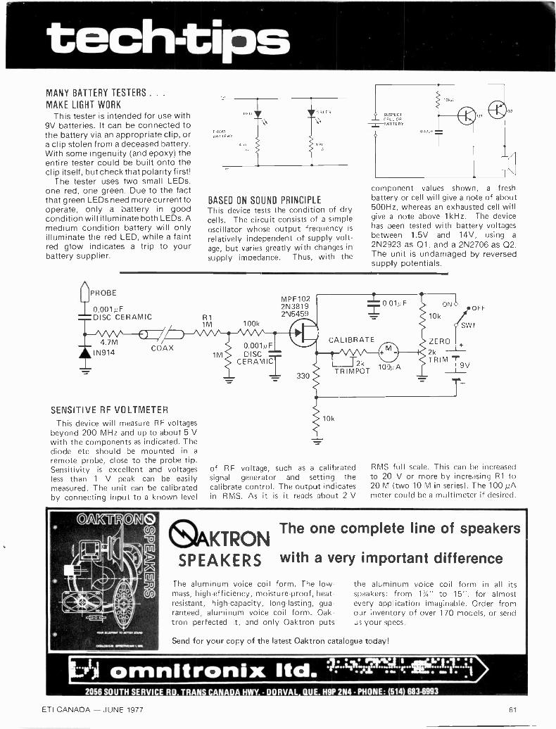
tech -tipsMANY BATTERY TESTERS . .
MAKE LIGHT WORKThis tester is intended for use with
9V batteries. It can be connected tothe battery via an appropriate clip, ora clip stolen from a deceased battery.With some ingenuity (and epoxy) theentire tester could be built onto theclip itself, but check that polarity first!
The tester uses two small LEDs,one red, one green. Due to the factthat green LEDs need more current tooperate, only a battery in goodcondition will illuminate both LEDs. Amedium condition battery will onlyilluminate the red LED, while a faintred glow indicates a trip to yourbattery supplier.
PROBE
BASED ON SOUND PRINCIPLEThis device tests the condition of drycells. The circuit consists of a simpleoscillator whose output frequency isrelatively independent of supply volt-age, but varies greatly with changes insupply impedance. Thus, with the
SUSPECTCELL OR
-13R-TTERY
04],F
10kif
component values shown, a freshbattery or cell will give a note of about500Hz, whereas an exhausted cell willgive a note above 1kHz. The devicehas been tested with battery voltagesbetween 1.5V and 14V, using a
2N2923 as 01, and a 2N2706 as Q2.The unit is undamaged by reversedsupply potentials.
0.001;;FDISC CERAMIC
4.7MIN914
COAX
SENSITIVE RF VOLTMETER
This device will measure RF voltagesbeyond 200 MHz and up to about 5 Vwith the components as indicated. Thediode etc should be mounted in a
remote probe, close to the probe tip.Sensitivity is excellent and voltagesless than 1 V peak can be easilymeasured. The unit can be calibratedby connecting input to a known level
R11M 100k
0.001µF1M DISC
CERAMIT
MPF1022N38192N5459
330
CALIBRATE
10k
2k 100u ATRIMPOT
of RF voltage, such as a calibratedsignal generator and setting thecalibrate control. The output indicatesin RMS. As it is it reads about 2 V
10k/S:
ONOOFF
ZERO
2kTRIM -r9V
T
RMS full scale. This can be increasedto 20 V or more by increasing R1 to20 M (two 10 M in series). The 100 pAmeter could be a multimeter if desired.
0
&KTRON The one complete line of speakers
SPEAKERS with a very important difference
The aluminum voice coil form. The low -mass, high -efficiency, moisture -proof, heat -resistant, high -capacity, long-lasting, gua-ranteed, aluminum voice coil form. Oak-tron perfected it, and only Oaktron puts
the aluminum voice coil form in all itsspeakers: from 1%" to 15", for almostevery application imaginable. Order fromour inventory of over 170 models, or sendus your specs.
Send for your copy of the latest Oaktron catalogue today!
...r omnitronix ltd. 1 .;2056 SOUTH SERVICE RD. TRANS CANADA HWY. - DORVAL QUE. H9P 2N4 - PHONE: 514 683-6993
ETI CANADA JUNE 1977 61

tech -tipsTANG BENTAT 900
SOLDERFIXED WITH
OR EPDXY
SLOT IN FRONTPANEL
ROTARY POT
SLIDER POT
JOYSTICK ALTERNATIVEShown is an idea used successfully toprovide a 'joystick' type of controlwith a television football game, bymounting an ordinary rotary typepotentiometer on the tang of a sliderpotentiometer. The rotary control is
attached to the circuit board via flyingleads.
Radio control enthusiasts could usethe idea in conjunction with a proport-ional system, giving a very cheapalternative to 'joysticks'.
741 TIMER
DRIFT FREE CURRENT SOURCE
The conventional current source isshown in Fig. 1. The idea is to set Vbat some reference level, in this casewith the two diodes biased by R1,making Vb=1.2V. The base - emitterdrop of 01, about the same as a diodedrop, or 0.6V, will fix Ve at 0.6V in thiscase. The emitter current through R2is thus set to le=Ve/R2. The emittercurrent multiplied by transistor alpha(typically .98 or .99) gives thecollector current. Hence we havearrived at a constant source ofcurrent.
This circuit does have a drawback.For a few minutes after the circuit isswitched on, the base -emitter dropwhich we have assumed to beconstant, actually changes due topower dissipation of the transistor.This drift may be around 4% for asmall signal transistor dissipating100mW.
This effect may be minimized by acouple of simple approaches. Oneway is to redesign the circuit so thatthe base - emitter drop is lesssignificant compared to Ve, so thatchanges in that drop have less effecton the current through R2. This maybe achieved by using a Zener in placeof diodes to generate a higher Vb, andrecalculating Ve and R2 for therequired current.
An alternative scheme (Fig. 2)employs an additional transistor (Q2)to dissipate most of the heat, whilethe dissipation in 01, and thus alsodrift, are reduced.
The circuit shows a very simple timerbased on a 741 op amp.
R1 and R2 hold the inverting inputat half supply voltage. R4 applies somefeedback to increase the input imped-ance at pin 3, but its value is such thatnegligable damping of pin 2's voltageoccurs. Pin 3, the non inverting input,is connected to the junction of R3 andC. After S1 is opened and C chargesvia R3. When the capacitor hascharged up sufficiently for the potent-ial at pin 3 to exceed that at pin 2the output abruptly changes from OVto positive line potential. If reversepolarity operation is required simplytranspose R3 and C.
R3 and C can be any values andtime delays from a fraction of a sec-ond to several hours can be obtained
4x1N914
Fig. 1
R1
Fig. 2
OV
V+ (10-30V)
lconst
R1 R3
2
R2
4k7
7
741 MINI DIP
R4
Q2
01
R2
OV
+6-35VO
0/P
OV
0by judicious selection. The time delay and R in ohms and hence is completelyis 0.7CR seconds where C is in Farads independent of supply voltage.
62 ETI CANADA - JUNE 1977
AD INDEXAbbey Electronics 2Active Electronic Sales Corp. 4Canmos Electronics 10Dominion Radio & Electronics 3ETCO Electronics 10Gamasonic Canada Ltd/Ltee. 11
Hammond Manufacturing Co. Ltd, 60J & J Electronics Ltd., 10Omnitronix Ltd., 60, 61, 63Philips Consumer Service 48Sprague International Ltd., OBCTenco Electronics Ltd., 60
INFORMATIONSUBSCRIPTIONSThe annual subscription to ETI for Canadian readers is$12.00, a two year subscription is $20.00. For U.S. sub-scribers, one year is $15.00, two years is $26.00. Pleasesend orders to ETI Subscriptions Dept.
PUBLICATIONSAt the moment we have five special publications available- Circuits No. 1 ($5.00), Top Projects Nos. 3 and 4,($2.50 each) and Electronics - It's Easy, Vols 1 and 2($3.50 each or $6.00 the pair). Orders to ETI SpecialsDept. please.
Classified Advertising RatesMinimum charge $27.00 per insertionMinimum size One inch depth by one column wide (21/4").Allow 36 letters and/ or spaces per line.Bold face Heading and Signature $3.00 extra.Otherwise only FIRST word and NAME set in bold caps.
Nine lines of thissize of type toone inch depth,
Nine lines ofthis size oftype to one inchdepth, includingHeading andSignatureand whitespace ifused.
Advance payment required except for classified ads placed by recognizedadsertising agencies. 1.0. Box not accepted unless adsertiscrs pros idespermanent acdress and phone number. HM; discount on consecutiseinsertions without corn change. Cop). must be received weeks proceedingmonth of issue.
Semi -Display Advertising RateCamera read) cops must he supplied or work w ill he billed hack to client.discount on repeat insertions without change. Payment in athanee.exrept torrecognized agencies. Deadline X weeks prececding month of issue.
0.7" Led ClockModule
4 Dl9Its Alarrn ClockLT70IE, 60Hz
$13.50 12 hr. display
EACH LT7°16. 6° Hz24 hr. display
Power Supply I2V ACIdeal for panel clock. deskclock, or auto clock kit
COMPANY NAME AND ADDRESS HERE
One size onlyOne column, 2" wideby I" inch depthCost $40.00per insertion
Send copy and cheque or money order toETI Magazine; Classified Advertising Dept.,
25 Overlea Blvd, Unit 6,TORONTO, Ontario, M4H 1BI
SPEC FOR SPEC
LEADER DELIVERS THE BEST PRICES AVAILABLE
.-77z.1`
LEADER TEST INSTRUMENTS p.
t.
If you haven't already comparedLEADER'S wide range of functional
oscilloscopes, do so! The prices, specsand warranty are better than what yoiare probably looking for. Probes and
accessories included.
omnitronix ltd. 1:-4'!7:015-1.4:-KIIILE2056 SOUTH SERVICE RDTRANS vCANA H W
"PUT US TO THE TEST." WRITE FOR OUR DETAILED CATALOG. DORVAL QUEDA
H9 2N4PHONE (514) 683-6993
ETI CANADA - JUNE 1977 63

WHO IS THE ONLY SUPPLIER WITH0 8 MAJOR TYPES OF 'LYTIC REPLACEMENT CAPACITORS
FOR ENTERTAINMENT ELECTRONICS?
SPRAGUE. Don't waste valuable service timechasing down capacitor replacements . . . Seeyour Sprague Distributor for all your 'lytic needsand you'll be able to put more time into actualservice work ... that's where the profit dollars are!
TYPE TVL TWIST-LOK® CAN -TYPE ELECTROLYTICSLock in place with twist
of tabs. Sealed aluminumcases for long life. With-
stand high surge voltages,high ripple currents, hightemperatures. Single, dual,triple, and quadruple sec-tion units. Capacitancevalues from 2 to 5000 µF.Voltage ratings from 6 to600 WVDC.
TYPE EE MINILYTIC® MINIATURE ELECTROLYTICSCompetitively priced, yet
substantially higher qualitythan most imported capac-
itors. Low leakage currentsassure minimum drain andlonger battery life in bypassapplications. Also ideal ascoupling capacitors. Capac-itance values from 1 to 2500µF. Voltage ratings from 3to 150 WVDC.
TYPE PCL PRINT-LOK® CAN -TYPE ELECTROLYTICSUniversal printed wiring
board mounting base.Sealed aluminum cases forlong life. Withstand high
surge voltages, high ripplecurrents, high temperatures.Etched cathode construc-tion. Ideal for selenium rec-tifier circuits. Single, dual,triple, and quadruple sec-tion units. Capacitancevalues from 2 to 3000 µF.
/ Voltage ratings from 3 to500 WVDC.
TYPE WH13D ECONOMY ULTRA -SMALL ELECTROLYTICSExcellent replacements
for capacitors of this typein miniaturized solid-state
circuitry, especially wherehigh volumetric efficiency,low cost, and dependableperformance are importantconsiderations. Metal -encased, with plastic insu-lating sleeve. Capacitancevalues from 1.5 to 3300 µF.Voltage ratings from 3 to100 WVDC.
TYPE EV VERTI-LYTIC® SINGLE -ENDED ELECTROLYTICSFor vertical installation
on high -density printed wir-ing boards. Used for cou-
pling, decoupling, bypass,filtering. Excellent capac-itance stability. Low leakagecurrent, low ESR. Metal -encased, with plastic insu-lating sleeve. Capacitancevalues from .47 to 3300 µF.Voltage ratings from 6.3 to63 WVDC.
TYPE TE LITTL-LYTIC® 105° C ELECTROLYTICSWithstand 2000 hr. life
test at rated voltage andmax. temperature of 105°C.
Most other low-cost minified'lytics of this type designedfor shorter test at lowertemperature. High capac-itance stability, even afterdrastic temperature change.Capacitance values from 1to 800 µF. Voltage ratingsfrom 3 to 150 WVDC.
TYPE TVA ATOM® STANDARD TUBULAR 'LYTICSDependable metal case
construction with plastic in-sulating sleeve. Withstandhigh temperatures, high rip -
ple currents, high surgevoltages. Low leakage cur-rents. Long shelf life. De-signed for operation attemperatures to 85°C. Sin-gle, dual, triple, quadruple,and quintuple units. Capac-itance values from 1 to50,000 µF. Voltage ratingsfrom 1 to 600 WVDC.
For complete listings of more than SMITH-PATTERSON5600 replacement components get & ASSOCIATESCatalog CC -621 from your Sprague 1120 Hamilton St.distributor, or write to: Vancouver, B.C. R3E 2T1
THE BROAD -LINE PRODUCER OF ELECTRONIC PARTS
TYPE AM ANTENNA ROTATOR ELECTROLYTICSAluminum electrolytic
capacitors of correct sizeand rating for all popular
Or JOHN R. TILTON, LTD.1900A Eglinton Ave. EastScarborough, OntarioM1L 2M1
makes of antenna rotators.Metal -encased with plasticinsulating sleeve. Single -ended design, with longflexible insulated leads.Choice of four different ca-pacitors to provide exactreplacement.
55.7100,42
SPRAGUETHE MARK OF RELIABILITY